WO2020026348A1 - 車両の制御方法及び制御装置 - Google Patents
車両の制御方法及び制御装置 Download PDFInfo
- Publication number
- WO2020026348A1 WO2020026348A1 PCT/JP2018/028684 JP2018028684W WO2020026348A1 WO 2020026348 A1 WO2020026348 A1 WO 2020026348A1 JP 2018028684 W JP2018028684 W JP 2018028684W WO 2020026348 A1 WO2020026348 A1 WO 2020026348A1
- Authority
- WO
- WIPO (PCT)
- Prior art keywords
- driving force
- upper limit
- acceleration
- vehicle
- target
- Prior art date
- Legal status (The legal status is an assumption and is not a legal conclusion. Google has not performed a legal analysis and makes no representation as to the accuracy of the status listed.)
- Ceased
Links
Images





Classifications
-
- B—PERFORMING OPERATIONS; TRANSPORTING
- B60—VEHICLES IN GENERAL
- B60W—CONJOINT CONTROL OF VEHICLE SUB-UNITS OF DIFFERENT TYPE OR DIFFERENT FUNCTION; CONTROL SYSTEMS SPECIALLY ADAPTED FOR HYBRID VEHICLES; ROAD VEHICLE DRIVE CONTROL SYSTEMS FOR PURPOSES NOT RELATED TO THE CONTROL OF A PARTICULAR SUB-UNIT
- B60W30/00—Purposes of road vehicle drive control systems not related to the control of a particular sub-unit, e.g. of systems using conjoint control of vehicle sub-units
- B60W30/18—Propelling the vehicle
- B60W30/188—Controlling power parameters of the driveline, e.g. determining the required power
Definitions
- the present invention relates to a control method and a control device for a vehicle that limits a target driving force by an upper limit driving force.
- JP 2009-227025A discloses a method of setting a target driving force and controlling a power train to realize the target driving force.
- the method of calculating the actual acceleration using the rotation speed of the wheel detected by the vehicle speed sensor it is difficult to accurately calculate the driving force, for example, in an extremely low vehicle speed region immediately after the start, so that it is difficult to accurately control the driving force.
- the acceleration sensor determines that the pitching operation of the vehicle at the start of acceleration is acceleration and detects the acceleration. Also, it is difficult to accurately calculate the acceleration due to the detection of the acceleration including.
- the change in the actual driving force is suppressed by limiting the upper limit of the target driving force, and thereby the acceleration of the vehicle is suppressed.
- an object of the present invention is to realize a target acceleration while suppressing excessive vehicle acceleration regardless of the presence or absence of a disturbance factor or the like.
- a target upper limit acceleration of the vehicle is set, an upper limit driving force according to the target upper limit acceleration is set, and the upper limit of the target driving force is limited by the upper limit driving force.
- the upper limit driving force is increased and corrected.
- FIG. 1 is a configuration diagram of a vehicle equipped with a vehicle control device.
- FIG. 2 is a configuration diagram of the control system.
- FIG. 3 is a diagram showing a control routine of the correction control of the upper limit driving force.
- FIG. 4 is a table used when calculating the target upper limit acceleration.
- FIG. 5 is a diagram showing a calculation routine of the actual acceleration.
- FIG. 6 is a timing chart for explaining the relationship between the vehicle speed and the acceleration detected by the vehicle speed sensor.
- FIG. 7 is a diagram illustrating a control routine for calculating a correction amount of the upper limit driving force.
- FIG. 8 is a timing chart for explaining the basic control of the present embodiment.
- FIG. 9 is a timing chart when the correction control of the upper limit driving force of the present embodiment is executed.
- FIG. 10 is a diagram illustrating a control routine of a correction control of an upper limit driving force according to a modification of the present embodiment.
- FIG. 1 is a configuration diagram of a vehicle 10 equipped with the vehicle control device according to the present embodiment.
- the vehicle 10 includes the engine 5 as a power source.
- the engine 5 a gasoline engine or a diesel engine is used.
- the “own vehicle” refers to the vehicle 10.
- the vehicle 10 includes a travel control controller 1, an engine controller 2 as a driving force control unit, a front camera 3 as an external world detection unit, a navigation system 4, and a vehicle speed sensor 6.
- the front camera 3 is arranged, for example, in the vicinity of a room mirror with the vehicle traveling direction facing, and sets the vehicle traveling direction as an imaging area (F1 in the figure).
- the navigation system 4 is arranged in the vehicle interior.
- the navigation system 4 sets a traveling route to a destination input by the driver based on map information stored in advance and position information from an artificial satellite.
- the vehicle speed sensor 6 is a non-contact type sensor that is disposed near a driving wheel (not shown) and that transmits a change in magnetic field generated by a sensor rotor that rotates with the driving wheel to the travel control controller 1 by converting the change into a pulse signal.
- the traveling controller 1 and the engine controller 2 are arranged in the engine compartment in front of the vehicle body as shown. In addition, these may be arrange
- Each of the traveling controller 1 and the engine controller 2 includes a microcomputer having a central processing unit (CPU), a read-only memory (ROM), a random access memory (RAM), and an input / output interface (I / O interface). .
- the travel control controller 1 and the engine controller 2 can each be constituted by a plurality of microcomputers.
- FIG. 2 is a configuration diagram of a control system centered on the control device according to the present embodiment.
- the front camera 3 outputs the captured image data to the traveling control controller 1.
- the image data is, for example, a stop line on a road surface, a state of a traffic light, a vehicle running around the own vehicle, and the like.
- the detection signal of the vehicle speed sensor 6 is also input to the travel controller 1.
- the travel controller 1 calculates the vehicle speed based on the detection signal of the vehicle speed sensor 6.
- the calculated vehicle speed is used not only for the control by the traveling control controller 1 but also for the control by the engine controller 2 to be transmitted to the engine controller 2.
- the traveling control controller 1 executes the traveling support control such as the automatic driving control or the so-called cruise control, the traveling control controller 1 performs the traveling control including starting and stopping of the vehicle based on the input information and the detection signal.
- the traveling support control such as the automatic driving control or the so-called cruise control
- the traveling control controller 1 sets a target vehicle speed and a target acceleration based on the target vehicle speed, and sets a target driving force for realizing the target acceleration.
- the target vehicle speed referred to here is a target vehicle speed set by the driver operating a target vehicle speed setting switch (not shown) or the like or a speed limit of a road on which the vehicle runs, and is set based on map information of the navigation system 4, for example. Further, when the vehicle follows the preceding vehicle, the vehicle speed capable of maintaining the inter-vehicle distance with the preceding vehicle is set as the target vehicle speed.
- the traveling control controller 1 sets a target vehicle speed based on the inter-vehicle distance or the vehicle speed of the preceding vehicle acquired by using the front camera 3 or a radar (not shown), and sets the target acceleration based on the current vehicle speed. To accelerate. A method for setting the target acceleration will be described later.
- the target acceleration and the target driving force set by the travel controller 1 are input to the engine controller 2 through communication via a CAN (Controller Area Network). Note that a target acceleration and a target driving force determined in advance by the vehicle controller 1 and the engine controller 2 may be used.
- CAN Controller Area Network
- the engine controller 2 limits the upper limit of the target acceleration by using the upper limit acceleration set from the viewpoint of safety and not giving the occupant of the vehicle an excessive feeling of acceleration.
- the target acceleration whose upper limit is limited is referred to as a target upper limit acceleration.
- the engine controller 2 sets an upper limit driving force according to the target upper limit acceleration, and when the target driving force is equal to or more than the upper limit driving force, limits the target driving force by the upper limit driving force.
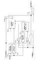
- FIG. 3 is a diagram showing a control routine of the upper-limit driving force correction control executed by the engine controller 2.
- FIG. 4 is a table used when calculating a target upper limit acceleration described later.
- FIG. 5 is a diagram showing a calculation routine of the actual acceleration.
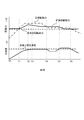
- FIG. 6 is a timing chart for explaining the relationship between the vehicle speed detected by the vehicle speed sensor 6 and the acceleration. The solid line in FIG. 6 shows the detected value of the vehicle speed sensor 6 and the acceleration calculated based on the detected value, and the broken line shows the actual vehicle speed and acceleration.
- FIG. 7 is a diagram illustrating a calculation routine of an upper limit driving force correction amount described later.
- FIGS. 8 and 9 are timing charts for explaining the operation and effect of the present embodiment.
- the control routines of FIGS. 3, 5 and 7 are programmed in the engine controller 2.
- the engine controller 2 performs the calculation of the target upper limit acceleration (B100), the calculation of the actual acceleration (B101), and the acceleration calculation state determination (B105) based on the vehicle speed (read vehicle speed) detected by the vehicle speed sensor 6. .
- the calculation of the target upper limit acceleration is performed, for example, by searching a table shown in FIG. 4 based on the read vehicle speed.
- a smaller target upper limit acceleration is set as the vehicle speed increases.
- a plurality of tables may be prepared, and the table to be used may be selected according to the situation.
- a general road table and an expressway table may be prepared, and which table to use may be determined based on information from the navigation system 4.
- the target upper limit acceleration is set higher in the expressway table than in the general road table when compared at the same vehicle speed.
- a table for the eco mode and a table for the normal mode which emphasize fuel efficiency, may be prepared, and a table corresponding to the current mode may be used.
- the target upper limit acceleration is set lower in the eco mode table than in the normal mode table when compared at the same vehicle speed. Further, a plurality of tables according to the presence or absence of the vehicle in front and the inter-vehicle distance may be made easy, and the table to be used may be determined based on the detection signals of the front camera 3 and a radar (not shown). In this case, the target upper limit acceleration is set lower than when there is no vehicle ahead, and the target upper limit acceleration is set lower as the inter-vehicle distance is shorter.
- the engine controller 2 compares a read vehicle speed minimum value (B200), which will be described later, with the read vehicle speed and selects the larger one (B201), and converts the selected vehicle speed into an acceleration by differentiating the selected vehicle speed with time (B202).
- the actual acceleration is obtained by filtering the acceleration (B203).
- the filtering process is a process for removing so-called noise data.
- the minimum read vehicle speed value is a value stored in the engine controller 2 in advance, and is, for example, the minimum vehicle speed VSPmin detectable by the vehicle speed sensor 6.
- the detection value of the vehicle speed sensor 6 that is, the read vehicle speed
- the read vehicle speed changes stepwise from zero to the minimum vehicle speed VSPmin. Therefore, if the acceleration is simply calculated from the read vehicle speed, the acceleration at the timing T2 becomes infinite. Therefore, as described above, the larger one of the read vehicle speed and the minimum vehicle speed VSPmin is converted into acceleration.
- the acceleration gradually increases from the timing T2.
- the engine controller 2 also calculates the jerk, which is the rate of change of the actual acceleration per unit time (B101).
- the calculation of the actual acceleration is not limited to the above method, but may be performed by another known method.
- a smoothing process may be performed so that the acceleration calculated from the read vehicle speed does not become infinite.
- Acceleration calculation state determination is for determining whether or not acceleration calculation based on the detection value of the vehicle speed sensor 6 is possible. For example, if the read vehicle speed is higher than the minimum vehicle speed VSPmin, it is determined that acceleration can be calculated.
- the engine controller 2 compares the target driving force with a later-described basic limited driving force (B106), and compares the target driving force with an upper-limit driving force corrected by the previous calculation described later (B104).
- the basic limited driving force is a value obtained by multiplying a vehicle weight in an empty state by a target upper limit acceleration and adding a running resistance. That is, the driving force is required to accelerate an empty vehicle to the target upper limit acceleration.
- the engine controller 2 When it is determined in the acceleration calculation state determination (B105) that the acceleration calculation is possible and the basic limited driving force is equal to or less than the target driving force (B106), the engine controller 2 permits the correction of the upper limit driving force, If not, the correction of the upper limit driving force is terminated and the correction amount is reset (B107).
- the engine controller 2 calculates the target upper limit acceleration, the actual acceleration, and the jerk based on the target upper limit driving force.
- An upper limit driving force correction amount is calculated (B102). The calculation of the upper limit driving force correction amount (B102) will be described later.
- the engine controller 2 adds the upper limit driving force correction amount and the basic limited driving force (B103), compares this with the target driving force, and sets the smaller one as the limited driving force (B108).
- the process of B102 is so-called PID control. Basically, when the actual acceleration has not reached the target upper-limit acceleration while the driving force has reached the upper-limit driving force, the upper-limit driving force increases. A correction amount is calculated. On the other hand, in the process of B102, when the actual acceleration exceeds the target upper-limit acceleration, a correction amount that reduces the upper-limit driving force is calculated.
- PID control Basically, when the actual acceleration has not reached the target upper-limit acceleration while the driving force has reached the upper-limit driving force, the upper-limit driving force increases. A correction amount is calculated.
- a correction amount that reduces the upper-limit driving force is calculated.
- the engine controller 2 calculates an error between the target upper limit acceleration and the actual acceleration (B300).
- the engine controller 2 compares the error with a later-described threshold (B301), and if the error is larger than the threshold, multiplies the error by a differential gain if the jerk is equal to or greater than a predetermined value (B302).
- the processing of B301 and B302 is processing for suppressing the overshoot of the actual acceleration. That is, when the actual acceleration approaches the target upper-limit acceleration and the jerk is equal to or more than the predetermined value, the upper-limit driving force correction amount is set to a value that reduces the upper-limit driving force. If the upper limit driving force decreases, the actual acceleration also decreases, and as a result, overshoot is suppressed.
- the degree of overshoot decreases as the jerk decreases. If the upper limit driving force is reduced even though overshoot is not a problem, the acceleration performance is unnecessarily reduced.
- a threshold value that can suppress overshoot while suppressing a decrease in acceleration performance is set.
- a threshold value of about 0.05 [G] may be set, but it is desirable to set the threshold value for each vehicle to which this embodiment is applied.
- multiplying the error by the differential gain is limited to the case where the jerk is equal to or more than a predetermined value.
- the predetermined value used here is set by adaptation similarly to the above threshold value.
- the magnitude of the differential gain may be changed according to the magnitude of the jerk. In this case, the higher the jerk, the larger the differential gain.
- the engine controller 2 executes a process of multiplying the error by the proportional gain (B303) and a process of multiplying the error by the integral gain (B304).
- the engine controller 2 compares the error with zero (B306), and performs the integration ON / hold determination based on the comparison result and the determination result in B104 (B307).
- the integration ON / hold determination is for determining whether to execute integration (to be described later) (ON) or to maintain the current integration value (hold). Specifically, when the error is less than zero, or when it is determined in B104 that the target driving force is equal to or more than the upper limit driving force, it is determined to execute the integration.
- the engine controller 2 adds the respective calculation results of B302, B303 and B305 (B308). If the correction of the upper limit driving force is permitted in the process of B107, the engine controller 2 selects the calculation result of B308 and is permitted. If not, zero is selected (B309). The engine controller 2 converts the value selected in B309 into driving force (B310), and sets this as the upper limit driving force correction amount. The conversion into the driving force is performed by a known method using the vehicle weight or the like.
- FIG. 8 is a timing chart for explaining the basic control of the present embodiment, and shows a case where the target driving force increases and the state is maintained.
- the solid line represents the post-restriction driving force
- the broken line represents the basic restriction driving force
- the dashed line represents the target driving force.
- the acceleration chart the solid line represents the actual acceleration
- the broken line represents the target upper limit acceleration.
- the target driving force starts to increase at timing T1, and the actual acceleration starts to increase accordingly.
- the upper limit of the target driving force is not limited (B106, B107).
- the engine controller 2 sets the post-restriction driving force obtained by increasing the basic restriction driving force and limits the upper limit of the target driving force with the post-restriction driving force.
- the engine controller 2 maintains the post-restriction driving force constant. Then, when the actual acceleration becomes higher than the target upper limit acceleration due to a change in road gradient or the like, the engine controller 2 reduces the post-restriction driving force (from timing T5 to timing T6). As a result, the actual acceleration decreases and returns to the target upper limit acceleration.
- FIG. 9 is a timing chart in the case where the control of the present embodiment is executed in a situation where the target driving force once increases and then decreases.
- the solid line represents the post-restriction driving force
- the broken line represents the basic restriction driving force
- the dashed line represents the target driving force.
- the acceleration chart the solid line represents the actual acceleration
- the broken line represents the target upper limit acceleration.
- timing T0 to timing T1 From timing T0 to timing T1, it is the same as timing T1 to timing T2 in FIG.
- the engine controller 2 sets a limited driving force obtained by increasing the basic limited driving force and increases the upper limit of the target driving force. As a result, the actual acceleration continues to increase.
- the engine controller 2 decreases the post-restriction driving force (B301, B302). ). Since the jerk of the actual acceleration also decreases as the post-restriction driving force decreases, the actual acceleration can be increased to the target upper limit acceleration while suppressing the overshoot of the actual acceleration from the target upper limit acceleration.
- the actual acceleration is lower than the target upper limit acceleration, but the target driving force is smaller than the post-restriction driving force.
- the driving force is maintained (B104, B102). This is because the decrease in the actual acceleration in a state where the target driving force is smaller than the post-restriction driving force is accompanied by a decrease in the target driving force, which is different from the situation where the required acceleration cannot be realized due to the insufficient driving force. It is. If the post-restriction acceleration is corrected from the timing T4 to the timing T5, the post-restriction acceleration may endlessly increase, and the driver may be given an excessive feeling of acceleration when an acceleration request is made thereafter. According to the embodiment, this can be avoided.
- the engine controller 2 performs the reduction correction of the post-restriction driving force regardless of the magnitude relationship between the target driving force and the post-restriction driving force (B306, B307).
- the reason is as follows. For example, after increasing the post-restriction driving force on an uphill road, if the target driving force required to enter the downhill road and achieve the target upper-limit acceleration decreases, the state where the post-restriction driving force has increased is shown. If maintained, the actual acceleration may significantly exceed the target upper limit acceleration. Therefore, in the present embodiment, in order to suppress the actual acceleration from greatly exceeding the target upper limit acceleration, the post-restriction driving force is corrected to decrease as described above.
- the engine controller 2 Since the target driving force is smaller than the basic limited driving force after the timing T6, the engine controller 2 does not execute the post-limit driving force correction.
- the engine controller 2 sets the target upper limit acceleration of the vehicle, sets an upper limit driving force according to the target upper limit acceleration, and limits the upper limit of the target driving force by the upper limit driving force. Then, when the actual acceleration does not reach the target upper limit acceleration, the engine controller 2 increases and corrects the upper limit driving force. This makes it possible to achieve the target upper limit acceleration regardless of the presence or absence of a disturbance factor such as a road gradient.
- the target driving force is a driving force necessary to drive the vehicle at the set vehicle speed or to maintain a predetermined inter-vehicle distance with the preceding vehicle. That is, the present embodiment is executed at the time of automatic driving control or driving support control.
- the target upper limit acceleration is set based on the current vehicle speed. By setting the target upper limit acceleration for each vehicle speed, it is possible to realize an appropriate acceleration that does not give a driver a sense of incompatibility.
- the engine controller 2 executes the increase correction of the upper limit driving force only when the target driving force is equal to or more than the upper limit driving force (B104).
- the target driving force is smaller than the upper limit driving force, even if the actual acceleration has not reached the target upper limit acceleration, this is not due to the limitation of the driving force by the upper limit driving force.
- the upper limit driving force is increased and corrected, the upper limit driving force is increased more than necessary, and for example, when the vehicle is reaccelerated, the acceleration may be excessively large. According to the present embodiment, it is possible to suppress the acceleration from excessively increasing as described above.
- the engine controller 2 corrects the lower limit of the upper limit driving force (B306) regardless of whether the target driving force is larger than the upper limit driving force. For example, when switching from an uphill road to a downhill road, the driving force required to achieve the target upper-limit acceleration decreases. In this case, if the increased upper limit driving force is maintained as it is on the uphill road, the actual acceleration may greatly exceed the target upper limit acceleration on the downhill road. In this regard, in the present embodiment, the upper limit driving force is reduced when the target upper limit acceleration becomes lower than the actual acceleration, so that the actual acceleration can be prevented from greatly exceeding the target upper limit acceleration as described above.
- the engine controller 2 corrects the upper limit driving force to decrease. (B301, B302). Thus, overshoot of the actual acceleration with respect to the target upper limit acceleration can be suppressed.
- the lower limit vehicle speed that can be detected by the vehicle speed sensor is set to the minimum value of the actual vehicle speed. (B101).
- the correction of the upper limit driving force is performed after a predetermined time elapses after the vehicle speed sensor 6 can detect the vehicle speed. You may start. This is based on the technical idea that the vehicle speed sensor 6 cannot detect the vehicle speed at an extremely low vehicle speed, and does not correct the upper limit driving force in this vehicle speed range. Immediately after the vehicle speed can be detected, the detection result indicates that the vehicle speed has rapidly increased from zero.Accurate acceleration cannot be calculated.Therefore, until a predetermined time elapses until the accurate acceleration can be calculated, The upper limit driving force is not corrected.
- the predetermined time here is determined according to the performance of the vehicle speed sensor 6 to be used.
- the correction of the upper limit driving force may be started.
- the correction of the upper limit driving force is started after the acceleration reaches a predetermined vehicle speed at which the accurate acceleration can be calculated.
- FIG. 10 is a modified example of the control routine of FIG.
- the description will focus on the differences from FIG.
- the correction amount of the upper limit driving force is calculated (B102), and the basic limit driving force is corrected with this correction amount (B103).
- a correction amount of the upper limit acceleration is calculated (B402), and a value obtained by correcting the target upper limit acceleration with this correction amount (B406) is used to calculate running resistance, vehicle weight, transmission gear ratio, and the like. Is converted into a driving force by a known method (B407).
- the calculation of the acceleration correction of ⁇ B402 is obtained by removing the conversion processing (B310) from the control routine of FIG. 7 into the driving force.
- the upper limit driving force is corrected using the driving force correction amount calculated based on the target upper limit acceleration and the actual acceleration.
- the upper limit acceleration is corrected using the acceleration correction amount calculated based on the target upper limit acceleration and the actual acceleration, and the corrected upper limit acceleration converted to the driving force is referred to as the limited driving force. I do. The same operation and effect can be obtained by either method.
Landscapes
- Engineering & Computer Science (AREA)
- Automation & Control Theory (AREA)
- Transportation (AREA)
- Mechanical Engineering (AREA)
- Control Of Vehicle Engines Or Engines For Specific Uses (AREA)
- Control Of Driving Devices And Active Controlling Of Vehicle (AREA)
Abstract
車両の目標上限加速度を設定し、目標上限加速度に応じた上限駆動力を設定し、目標駆動力の上限を上限駆動力により制限する車両の制御方法において、実加速度が目標上限加速度に到達しない場合には、上限駆動力を増大補正する。
Description
本発明は、目標駆動力を上限駆動力で制限する車両の制御方法及び制御装置に関する。
車両を加速させる際の制御として、JP2009-227025Aには、目標駆動力を設定し、当該目標駆動力を実現するようパワートレインを制御するものが開示されている。車両の加速時には、安全性を確保するため、及び乗員に過剰な加速感を与えないようにするために、加速度の上限を制限する必要がある。そのための制御として、制限された加速度に基づいて駆動力を制御することが考えられる。しかし、車速センサにより検出した車輪の回転速度を用いて実加速度を算出する方法では、例えば発進直後の極低車速領域では正確な加速度を算出できないため、駆動力制御を精度良く行なうことが難しい。また、加速度センサにより車両の加速度を検出する方法もあるが、加速度センサでは、加速開始時の車両のピッチング動作を加速と判定して検出してしまうことや、勾配路においては勾配に起因する加速度を含めた加速度を検出してしまうこと等により、やはり加速度を正確に算出することは難しい。
その点、上記文献では、目標駆動力の上限を制限することによって実駆動力の変化を抑制し、これにより車両の加速度を抑制している。
しかしながら、上記文献の制御のように目標駆動力の上限を制限すると、例えば道路勾配等といった外乱因子がある場合や、パワートレイン部品における動力損失が経年変化等により増大している場合等には、制限が過剰に効いて運転者が期待する加速度を実現できないおそれがある。
そこで本発明は、外乱因子等の有無にかかわらず、過剰な車両加速を抑制しつつ目標加速度を実現することを目的とする。
本発明のある態様による車両制御方法では、車両の目標上限加速度を設定し、目標上限加速度に応じた上限駆動力を設定し、目標駆動力の上限を上限駆動力により制限する。そして、実加速度が目標上限加速度に到達しない場合には、上限駆動力を増大補正する。
以下、図面等を参照して、本発明の実施形態について説明する。
図1は、本実施形態に係る車両制御装置を搭載する車両10の構成図である。
車両10は、動力源としてエンジン5を備える。エンジン5としてはガソリンエンジンまたはディーゼルエンジンを用いる。以下の説明において、「自車」とは車両10のことを指す。
また、車両10は、走行制御コントローラ1と、駆動力制御部としてのエンジンコントローラ2と、外界検知部としての前方カメラ3と、ナビゲーションシステム4と、車速センサ6と、を備える。
前方カメラ3は、例えばルームミラー付近に車両進行方向を向けて配置され、車両進行方向を撮像領域(図中のF1)とする。
ナビゲーションシステム4は、車室内に配置される。ナビゲーションシステム4は、予め記憶した地図情報と人工衛星からの位置情報とに基づいて、運転者が入力した目的地までの走行ルートを設定する。
車速センサ6は、図示しない駆動輪付近に配置され、駆動輪とともに回転するセンサロータによる磁界の変化をパルス信号に置き換えて走行制御コントローラ1に送信する非接触型のセンサである。
走行制御コントローラ1及びエンジンコントローラ2は、図示する通り車体前方のエンジン・コンパートメント内に配置される。なお、これらは車室内に配置されても構わない。
走行制御コントローラ1及びエンジンコントローラ2はいずれも中央演算装置(CPU)、読み出し専用メモリ(ROM)、ランダムアクセスメモリ(RAM)及び入出力インタフェース(I/Oインタフェース)を備えたマイクロコンピュータで構成される。走行制御コントローラ1及びエンジンコントローラ2を、それぞれ複数のマイクロコンピュータで構成することも可能である。
図2は、本実施形態に係る制御装置を中心とする制御システムの構成図である。
前方カメラ3は、撮像した画像データを走行制御コントローラ1へ出力する。画像データは、例えば、路面上の停止線や、信号機の状態や、自車の周辺を走行する車両等である。
ナビゲーションシステム4が有する地図情報に含まれる停止線や信号機の設置場所や、ナビゲーションシステム4が設定した走行ルートは、走行制御コントローラ1へ出力される。
また、走行制御コントローラ1には車速センサ6の検出信号も入力される。走行制御コントローラ1は、車速センサ6の検出信号に基づいて車速を算出する。算出された車速は、走行制御コントローラ1による制御に用いられるだけでなく、エンジンコントローラ2に送信され、エンジンコントローラ2による制御にも用いられる。
走行制御コントローラ1は、自動運転制御またはいわゆるクルーズコントロールのような走行支援制御を実行する場合には、入力された情報や検出信号等に基づいて、車両の発進・停止を含む走行制御を行なう。
走行制御コントローラ1は、車両を発進させる場合には、目標車速及び目標車速に基づく目標加速度を設定し、目標加速度を実現するための目標駆動力を設定する。ここでいう目標車速は、運転者が図示しない目標車速設定スイッチ等を操作して設定する目標車速や、走行する道路の制限速度であり、例えばナビゲーションシステム4の地図情報に基づいて設定する。また、前走車に追従走行する場合には、前走車との車間距離を維持し得る車速を目標車速とする。この場合、走行制御コントローラ1は前方カメラ3や図示しないレーダ等を用いて取得した車間距離や前走車の車速等に基づいて目標車速を設定し、現在の車速に基づいて設定した目標加速度で加速する。目標加速度の設定方法については後述する。
走行制御コントローラ1が設定した目標加速度及び目標駆動力は、CAN(Controller Area Network)を介した通信によってエンジンコントローラ2へ入力される。なお、車両制御コントローラ1とエンジンコントローラ2とで予め取り決められた目標加速度と目標駆動力とを用いるようにしてもよい。
ところで、例えばクルーズコントロールの実行中における目標駆動力については、道路勾配や路面の抵抗等といった環境要件に基づくフィードバック制御が行われる。そこで、フィードバック制御によって目標駆動力が過剰に大きくなることを防止する必要がある。また、CANに何らかの不具合が生じて走行制御コントローラ1からエンジンコントローラ2へ目標駆動力が正しく入力されなかった場合でも、加速度が過剰に大きくなることを防ぐために、目標駆動力の上限を制限する必要がある。
そこで、エンジンコントローラ2は、安全上の観点及び車両の乗員に過剰な加速感を与えないという観点から設定される上限加速度を用いて、目標加速度の上限を制限する。以下、上限を制限された目標加速度を目標上限加速度という。
目標加速度を制限するために、エンジンコントローラ2は、目標上限加速度に応じた上限駆動力を設定し、目標駆動力が上限駆動力以上の場合には目標駆動力を上限駆動力で制限する。
次に、上限駆動力の補正について、図3-図9を参照して説明する。
図3は、エンジンコントローラ2が実行する上限駆動力の補正制御の制御ルーチンを示す図である。図4は後述する目標上限加速度を演算する際に用いるテーブルである。図5は、実加速度の演算ルーチンを示す図である。図6は車速センサ6により検出される車速と加速度との関係を説明するためのタイミングチャートである。図6の実線は車速センサ6の検出値及び当該検出値に基づいて算出された加速度を示し、破線は実際の車速及び加速度を示している。図7は、後述する上限駆動力補正量の演算ルーチンを示す図である。図8、図9は、本実施形態の作用効果を説明するためのタイミングチャートである。図3、図5及び図7の制御ルーチンは、エンジンコントローラ2にプログラムされている。
まず、図3の制御ルーチンから説明する。
エンジンコントローラ2は、車速センサ6で検出した車速(読込車速)に基づいて、目標上限加速度の演算(B100)と、実加速度の演算(B101)と、加速度演算状態判定(B105)と、を行なう。
目標上限加速度の演算(B100)は、例えば図4に示すテーブルを読込車速で検索することにより行なう。図4のテーブルでは、車速が高いほど小さい目標上限加速度が設定されている。なお、複数のテーブルを用意しておき、状況に応じて使用するテーブルを選択してもよい。例えば、一般道用テーブルと高速道路用テーブルを用意しておき、ナビゲーションシステム4からの情報に基づいていずれのテーブルを使用するかを決定してもよい。この場合、同一車速で比べると高速道路用テーブルは一般道用テーブルより高い目標上限加速度が設定される。また、燃費重視のエコモード用テーブルと通常モード用テーブルとを用意しておき、現在のモードに応じたテーブルを使用してもよい。この場合、同一車速で比べるとエコモード用テーブルは通常モード用テーブルより低い目標上限加速度が設定される。さらに、前方車両の有無及び車間距離に応じた複数のテーブルを容易しておき、前方カメラ3や図示しないレーダの検出信号に基づいて使用するテーブルを決定してよい。この場合、前方車両がいる場合はいない場合に比べて目標上限加速度は低く設定され、また、車間距離が短いほど目標上限加速度は低く設定される。
実加速度の演算(B101)は、具体的には図5に示す演算ルーチンを実行する。ここで図5の演算ルーチンについて説明する。
エンジンコントローラ2は、後述する読込車速最小値(B200)と読込車速とを比較して大きい方を選択し(B201)、選択した車速を時間微分することで加速度に変換し(B202)、変換後の加速度をフィルタ処理(B203)したものを実加速度とする。フィルタ処理は、いわゆるノイズとなるデータを除去するための処理である。
読込車速最小値は、エンジンコントローラ2に予め記憶された値であり、例えば車速センサ6で検出可能な最低車速VSPminとする。図6に示す通り、実際にはタイミングT1で発進しても、車速が最低車速VSPminに到達するタイミングT2までは車速センサ6の検出値(つまり、読込車速)はゼロ[km/h]である。そして、タイミングT2で読込車速はゼロから最低車速VSPminにステップ的に変化する。このため、単純に読込車速から加速度を演算すると、タイミングT2における加速度は無限大となってしまう。そこで、上述した通り読込車速と最低車速VSPminとのうち大きい方を加速度に変換する。これにより、図6に実線で示す通り、加速度はタイミングT2から徐々に増大することとなる。
エンジンコントローラ2は、実加速度の単位時間当たりの変化率である躍度も演算する(B101)。
なお、実加速度の演算は上記の方法に限られるわけではなく、他の公知の方法により演算しても構わない。例えば、車速センサ6で検出可能な最低車速VSPmin付近の車速域については、読込車速から算出した加速度が無限大にならないようになまし処理してもよい。
加速度演算状態判定(B105)は、車速センサ6の検出値に基づく加速度演算が可能な状態であるか否かを判定するものである。例えば、読込車速が最低車速VSPminより大きい場合に加速度演算可能と判定する。
また、エンジンコントローラ2は、目標駆動力と後述する基本制限駆動力との比較(B106)と、目標駆動力と後述する前回演算による補正後の上限駆動力との比較(B104)と、を行なう。基本制限駆動力とは、空車状態における車重に目標上限加速度を乗じたものに走行抵抗を加算したものである。つまり、空車状態の車両を目標上限加速度まで加速させるのに必要な駆動力である。
エンジンコントローラ2は、加速度演算状態判定(B105)で加速度演算が可能であると判定され、かつ、基本制限駆動力が目標駆動力以下の場合に(B106)、上限駆動力の補正を許可し、そうでない場合は上限駆動力の補正を終了して補正量をリセットする(B107)。
エンジンコントローラ2は、目標駆動力が上限駆動力以上であり(B104)、かつ上限駆動力の補正が許可されている場合(B107)に、目標上限加速度と実加速度と躍度とに基づいて、上限駆動力補正量を演算する(B102)。上限駆動力補正量の演算(B102)については後述する。
エンジンコントローラ2は、上限駆動力補正量と基本制限駆動力とを加算し(B103)、これと目標駆動力とを比較して小さい方を制限後駆動力とする(B108)。
次に、上限駆動力補正量の演算(B102)について図7を参照して説明する。
B102の処理は、いわゆるPID制御であり、基本的には、駆動力が上限駆動力に達しているのに実加速度が目標上限加速度に到達していない場合には上限駆動力が増大するような補正量が算出される。一方、B102の処理では、実加速度が目標上限加速度を超えている場合には上限駆動力が減少するような補正量が算出される。以下、B102の処理について詳細に説明する。
エンジンコントローラ2は、目標上限加速度と実加速度との誤差を演算する(B300)。エンジンコントローラ2は誤差と後述する閾値とを比較し(B301)、誤差が閾値より大きい場合は、躍度が所定値以上であれば誤差に微分ゲインを乗算する(B302)。
B301及びB302の処理は、実加速度のオーバーシュートを抑制するための処理である。すなわち、実加速度が目標上限加速度に近づき、かつ躍度が所定値以上の場合に、上限駆動力補正量を、上限駆動力を低下させる大きさにするものである。上限駆動力が低下すれば実加速度も低下し、結果的にオーバーシュートが抑制される。
ただし、上限駆動力を低下させるタイミングが早くなるほど実加速度が低下するタイミングも早くなるので、適切なタイミングで上限駆動力を低下させないと加速性能の低下を招くこととなる。
また、躍度が小さくなるほどオーバーシュートの度合いは小さくなる。そして、オーバーシュートが問題にならない程度にもかかわらず上限駆動力を低下させると、無駄に加速性能を低下させることとなる。
そこで、加速性能の低下を抑制しつつオーバーシュートも抑制できる閾値を設定する。例えば0.05[G]程度の閾値を設定してもよいが、本実施形態を適用する車両毎に適合により設定することが望ましい。また、誤差に微分ゲインを乗算するのは躍度が所定値以上の場合に限定する。ここで用いる所定値は、上記閾値と同様に適合により設定する。
なお、誤差に微分ゲインを乗算する場合に、躍度の大きさに応じて微分ゲインの大きさを変化させるようにしてもよい。この場合、躍度が大きいほど微分ゲインを大きくする。
エンジンコントローラ2は、誤差に比例ゲインを乗算する処理(B303)と、誤差に積分ゲインを乗算する処理(B304)と、を実行する。
また、エンジンコントローラ2は誤差とゼロとを比較し(B306)、この比較の結果と上記B104の判定結果とに基づいて、積分ON/ホールド判定を行なう(B307)。積分ON/ホールド判定は、後述する積分を実行するか(ON)、現状の積分値を維持するか(ホールド)を決めるものである。具体的には、誤差がゼロ未満の場合、またはB104で目標駆動力が上限駆動力以上と判定された場合に、積分を実行すると判定する。
エンジンコントローラ2は、B307の処理において積分を実行すると判定され、B107の処理において上限駆動力の補正が許可された場合には、積分を実行する(B305)。
そして、エンジンコントローラ2はB302、B303及びB305のそれぞれの演算結果を加算し(B308)、B107の処理で上限駆動力の補正が許可された場合にはB308の演算結果を選択し、許可されていない場合はゼロを選択する(B309)。エンジンコントローラ2は、B309で選択された値を駆動力に変換し(B310)、これを上限駆動力補正量とする。駆動力への変換は、車重等を用いて公知の手法により行なう。
次に、上述した制御の作用効果について図8、図9を参照して説明する。
図8は、本実施形態の基本的な制御について説明するためのタイミングチャートであり、目標駆動力が増大し、その状態が維持される場合を表している。駆動力のチャートにおいて、実線は制限後駆動力を、破線は基本制限駆動力を、一点鎖線は目標駆動力をそれぞれ表す。加速度のチャートにおいて、実線は実加速度を、破線は目標上限加速度をそれぞれ表す。
タイミングT1で目標駆動力が増大し始め、これに応じて実加速度が上昇し始める。目標駆動力が基本制限駆動力より小さい期間、つまりタイミングT1からタイミングT2までは、目標駆動力の上限は制限されない(B106、B107)。
タイミングT2において、目標駆動力が基本制限駆動力に到達しているのに実加速度が目標上限加速度に到達していない。そこで、エンジンコントローラ2は基本制限駆動力を増大補正した制限後駆動力を設定し、この制限後駆動力で目標駆動力の上限を制限する。
目標駆動力の上限が上昇することで、実加速度は再び上昇して目標上限加速度に到達する(タイミングT3からタイミングT4)。タイミングT4で実加速度が目標上限加速度に到達したら、エンジンコントローラ2は制限後駆動力を一定に維持する。そして、道路勾配の変化等により実加速度が目標上限加速度より高くなったら、エンジンコントローラ2は制限後駆動力を減少させる(タイミングT5からタイミングT6)。これにより実加速度は低下して、目標上限加速度に戻る。
図9は、目標駆動力が一旦増大してから減少する状況で、本実施形態の制御を実行した場合のタイミングチャートである。駆動力のチャートにおいて、実線は制限後駆動力を、破線は基本制限駆動力を、一点鎖線は目標駆動力をそれぞれ表す。加速度のチャートにおいて、実線は実加速度を、破線は目標上限加速度をそれぞれ表す。
タイミングT0からタイミングT1までは、図8のタイミングT1からタイミングT2と同様である。
タイミングT1で目標駆動力が基本制限駆動力に到達しているのに、実加速度は目標上限加速度に到達していない。そこでエンジンコントローラ2は基本制限駆動力を増大補正した制限駆動力を設定して、目標駆動力の上限を上昇させる。これにより実加速度は上昇を続ける。
タイミングT2において、実加速度と目標上限加速度との誤差が上述した閾値より小さくなり、かつ躍度が上述した所定値以上の場合には、エンジンコントローラ2は制限後駆動力を減少させる(B301、B302)。制限後駆動力が減少することで実加速度の躍度も小さくなるので、実加速度の目標上限加速度に対するオーバーシュートを抑制しつつ実加速度を目標上限加速度まで上昇させることができる。
タイミングT4からタイミングT5では、実加速度が目標上限加速度より低くなるが、目標駆動力が制限後駆動力より小さいので、エンジンコントローラ2は制限後駆動力の補正を実行せずに、現状の制限後駆動力を維持する(B104、B102)。これは、目標駆動力が制限後駆動力より小さい状態における実加速度の低下は目標駆動力の減少に伴うものであって、駆動力不足に起因して必要な加速度が実現できない状況とは異なるからである。仮にタイミングT4からタイミングT5で制限後加速度の補正を行なうと、制限後加速度が際限なく上昇して、その後に加速要求が生じた場合に運転者に過剰な加速感を与えるおそれがあるが、本実施形態によればこれを回避できる。
タイミングT5からタイミングT6では、実加速度が目標上限加速度より大きくなっている。このときエンジンコントローラ2は、目標駆動力と制限後駆動力との大小関係によらず、制限後駆動力を減量補正する(B306、B307)。その理由は以下の通りである。例えば上り勾配路において制限後駆動力を増大させた後、下り勾配路に進入して目標上限加速度を実現するために必要な目標駆動力が減少した場合に、制限後駆動力が増大した状態を維持すると実加速度が目標上限加速度を大きく超えてしまうおそれがある。そこで本実施形態では、実加速度が目標上限加速度を大きく超えることを抑制するために、上記の通り制限後駆動力を減量補正する。
タイミングT6以降は、目標駆動力が基本制限駆動力より小さいのでエンジンコントローラ2は制限後駆動力の補正を実行しない。
次に、本実施形態に係る制御が奏する効果についてまとめる。
本実施形態では、エンジンコントローラ2は車両の目標上限加速度を設定し、目標上限加速度に応じた上限駆動力を設定し、目標駆動力の上限を上限駆動力により制限する。そして、エンジンコントローラ2は、実加速度が目標上限加速度に到達しない場合には上限駆動力を増大補正する。これにより、道路勾配等の外乱因子の有無にかかわらず、目標上限加速度を実現することができる。
本実施形態では、目標駆動力は、車両を設定車速で走行させるため又は前方車両との車間距離を所定距離に保つために必要な駆動力である。すなわち、本実施形態は、自動運転制御または運転支援制御の際に実行される。
本実施形態では、目標上限加速度を現在の車速に基づいて設定する。車速毎に目標上限加速度を設定することで、運転者に違和感を与えない適切な加速度を実現できる。
本実施形態では、目標駆動力が上限駆動力以上の場合に限り、エンジンコントローラ2は上限駆動力の増大補正を実行する(B104)。目標駆動力が上限駆動力より小さい場合は、実加速度が目標上限加速度に到達していないとしても、それは上限駆動力による駆動力の制限が原因ではない。このような場合に上限駆動力を増大補正してしまうと、必要以上に上限駆動力を増大させることとなり、例えば再加速する際に過剰に大きな加速度になるおそれがある。本実施形態によれば、上記のように加速度が過剰に大きくなることを抑制できる。
本実施形態では、目標上限加速度が実加速度より低くなった場合は、目標駆動力が上限駆動力より大きいか否かに関わらず、エンジンコントローラ2は上限駆動力を減少補正する(B306)。例えば、上り勾配路から下り勾配路に切り替わると、目標上限加速度を実現するために必要な駆動力は減少する。この場合、上り勾配路において増大させた上限駆動力をそのまま維持すると、下り勾配路になったときに実加速度が目標上限加速度を大きく超えてしまうおそれがある。その点、本実施形態では、目標上限加速度が実加速度より低くなったときに上限駆動力を減少させておくので、上記のように実加速度が目標上限加速度を大きく超えることを抑制できる。
本実施形態では、実加速度の上昇中に、実加速度と目標上限加速度との誤差が閾値より小さく、かつ躍度が所定値以上となった場合には、エンジンコントローラ2は上限駆動力を減少補正する(B301、B302)。これにより、目標上限加速度に対する実加速度のオーバーシュートを抑制できる。
本実施形態では、車速センサ6の検出値を用いて実車速を算出し、当該実車速を用いて実加速度を算出する場合には、車速センサで検出可能な下限の車速を実車速の最小値とする(B101)。これにより、車速センサ6で検出不可能な車速から検出可能な車速に変化したときに、実際よりも大きな加速度が演算されることを防止でき、さらに、ノイズ除去のためのフィルタを強める必要がなくなる。
なお、車速センサで検出可能な下限の車速を実車速の最小値として実加速度を算出する代わりに、上限駆動力の補正を、車速センサ6による車速の検出が可能になってから所定時間経過後に開始してもよい。これは、車速センサ6は極低車速においては車速を検出できないので、この車速域で上限駆動力の補正を行なわないという技術思想に基づく。また、車速を検出可能になった直後は、車速がゼロから急激に上昇したという検出結果となり、正確な加速度を演算できないので、正確な加速度を演算可能になるまでの所定時間が経過するまで、上限駆動力の補正を行なわない。ここでの所定時間は、使用する車速センサ6の性能に応じて定まる。
また、車速センサで検出可能な下限の車速を実車速の最小値とする、または車速センサ6による車速の検出が可能になってから所定時間経過後に上限駆動力の補正を開始する代わりに、実車速が車速センサで検出可能な下限の車速より高い所定車速になったら上限駆動力の補正を開始してもよい。上記の通り、車速センサ6が車速検知可能になった直後は正確な加速度を演算できない。そこで、本実施形態では、正確な加速度が演算可能な所定車速になってから、上限駆動力の補正を開始する。
次に、上記実施形態の変形例について説明する。本変形例も上記実施形態と同様に本発明の範囲内である。
図10は、図3の制御ルーチンの変形例である。以下、図3との相違点を中心に説明する。
図3の制御ルーチンでは、上限駆動力の補正量を演算し(B102)、この補正量で基本制限駆動力を補正する(B103)。これに対し図10の制御ルーチンでは、上限加速度の補正量を演算し(B402)、この補正量で目標上限加速度を補正したものを(B406)、走行抵抗、車重及び変速機の変速比等を用いて公知の方法で駆動力に変換する(B407)。
B402の加速度の補正の演算は、図7の制御ルーチンから駆動力への変換処理(B310)を除いたものである。
以上のように、上記実施形態では目標上限加速度と実加速度とに基づいて算出した駆動力補正量を用いて上限駆動力を補正する。これに対し本変形例では、目標上限加速度と実加速度とに基づいて算出した加速度補正量を用いて上限加速度を補正し、補正後の上限加速度を駆動力に変換したものを制限後駆動力とする。いずれの方法によっても同様の作用効果が得られる。
以上、本発明の実施形態について説明したが、上記実施形態は本発明の適用例の一部を示したに過ぎず、本発明の技術的範囲を上記実施形態の具体的構成に限定する趣旨ではない。
Claims (10)
- 車両の目標上限加速度を設定し、
前記目標上限加速度に応じた上限駆動力を設定し、
目標駆動力の上限を前記上限駆動力により制限する車両の制御方法において、
実加速度が前記目標上限加速度に到達しない場合には、前記上限駆動力を増大補正する、車両の制御方法。 - 請求項1に記載の車両の制御方法において、
前記目標駆動力は、車両を設定車速で走行させるため又は前方車両との車間距離を所定距離に保つために必要な駆動力である、車両の制御方法。 - 請求項1または2に記載の車両の制御方法において、
前記目標上限加速度を、現在の車速に基づいて設定する、車両の制御方法。 - 請求項1から3のいずれか一項に記載の車両の制御方法において、
前記目標駆動力が前記上限駆動力以上の場合に限り、前記上限駆動力の増大補正を実行する、車両の制御方法。 - 請求項1から4のいずれか一項に記載の車両の制御方法において、
前記目標上限加速度が前記実加速度より低くなった場合は、前記目標駆動力が前記上限駆動力より大きいか否かに関わらず、前記上限駆動力を減少補正する、車両の制御方法。 - 請求項1から5のいずれか一項に記載の車両の制御方法において、
前記実加速度の上昇中に、前記実加速度と前記目標上限加速度との誤差が閾値より小さく、かつ前記実加速度の単位時間あたりの変化率を表す躍度が所定値以上となった場合には、前記上限駆動力を減少補正する、車両の制御方法。 - 請求項1から6のいずれか一項に記載の車両の制御方法において、
車速センサの検出値を用いて実車速を算出し、当該実車速を用いて前記実加速度を算出する場合には、
前記車速センサで検出可能な下限の車速を前記実車速の最小値とする、車両の制御方法。 - 請求項1から6のいずれか一項に記載の車両の制御方法において、
車速センサによる車速の検出が可能になってから所定時間経過後に、前記上限駆動力の補正を開始する、車両の制御方法。 - 請求項1から6のいずれか一項に記載の車両の制御方法において、
実車速が車速センサで検出可能な下限の車速より高い所定車速になってから、前記上限駆動力の補正を開始する車両の制御方法。 - 車両の目標上限加速度を設定し、前記目標上限加速度に応じた上限駆動力を設定し、目標駆動力の上限を前記上限駆動力により制限する駆動力制御部を備える車両の制御装置において、
前記駆動力制御部は、実加速度が前記目標上限加速度に到達しない場合には前記上限駆動力を増大補正するようプログラムされている、車両の制御装置。
Priority Applications (1)
| Application Number | Priority Date | Filing Date | Title |
|---|---|---|---|
| PCT/JP2018/028684 WO2020026348A1 (ja) | 2018-07-31 | 2018-07-31 | 車両の制御方法及び制御装置 |
Applications Claiming Priority (1)
| Application Number | Priority Date | Filing Date | Title |
|---|---|---|---|
| PCT/JP2018/028684 WO2020026348A1 (ja) | 2018-07-31 | 2018-07-31 | 車両の制御方法及び制御装置 |
Publications (1)
| Publication Number | Publication Date |
|---|---|
| WO2020026348A1 true WO2020026348A1 (ja) | 2020-02-06 |
Family
ID=69231469
Family Applications (1)
| Application Number | Title | Priority Date | Filing Date |
|---|---|---|---|
| PCT/JP2018/028684 Ceased WO2020026348A1 (ja) | 2018-07-31 | 2018-07-31 | 車両の制御方法及び制御装置 |
Country Status (1)
| Country | Link |
|---|---|
| WO (1) | WO2020026348A1 (ja) |
Citations (4)
| Publication number | Priority date | Publication date | Assignee | Title |
|---|---|---|---|---|
| JP2004184130A (ja) * | 2002-11-29 | 2004-07-02 | Denso Corp | 車両用障害物認識装置 |
| JP2007126057A (ja) * | 2005-11-04 | 2007-05-24 | Toyota Motor Corp | 傾斜角推定装置 |
| JP2014213760A (ja) * | 2013-04-26 | 2014-11-17 | スズキ株式会社 | 車両用加速度算出装置 |
| JP2016183647A (ja) * | 2015-03-26 | 2016-10-20 | トヨタ自動車株式会社 | 車速制限装置 |
-
2018
- 2018-07-31 WO PCT/JP2018/028684 patent/WO2020026348A1/ja not_active Ceased
Patent Citations (4)
| Publication number | Priority date | Publication date | Assignee | Title |
|---|---|---|---|---|
| JP2004184130A (ja) * | 2002-11-29 | 2004-07-02 | Denso Corp | 車両用障害物認識装置 |
| JP2007126057A (ja) * | 2005-11-04 | 2007-05-24 | Toyota Motor Corp | 傾斜角推定装置 |
| JP2014213760A (ja) * | 2013-04-26 | 2014-11-17 | スズキ株式会社 | 車両用加速度算出装置 |
| JP2016183647A (ja) * | 2015-03-26 | 2016-10-20 | トヨタ自動車株式会社 | 車速制限装置 |
Similar Documents
| Publication | Publication Date | Title |
|---|---|---|
| CA3030812C (en) | Torque control method and torque control device | |
| US10112648B2 (en) | Vehicle steering device | |
| JP5369504B2 (ja) | 車両用走行制御装置 | |
| KR102555912B1 (ko) | 전기 모터를 구비하는 차량 및 그를 위한 주행 제어 방법 | |
| KR101628508B1 (ko) | 차량의 가속토크 제어 장치 및 방법 | |
| WO2017081714A1 (ja) | 制駆動力制御方法及び制駆動力制御装置 | |
| JP2016025683A (ja) | 車両走行制御装置 | |
| US10981555B2 (en) | Vehicle equipped with electric motor and parking control method therefor | |
| JP2021054275A (ja) | 走行制御装置 | |
| KR20200137061A (ko) | 차량의 크립 주행 제어 시스템 및 그 방법 | |
| KR102579862B1 (ko) | 전기 모터를 구비하는 차량 및 그를 위한 주행 제어 방법 | |
| KR101944485B1 (ko) | 저속 전기차용 속도 제어장치 | |
| JP5790795B2 (ja) | 減速因子推定装置 | |
| KR101788189B1 (ko) | 구배 변화에 따른 토크 제어 방법 및 장치 | |
| JP4949179B2 (ja) | 車両用走行制御装置 | |
| JP7139593B2 (ja) | 走行制御装置、車両、および走行制御方法 | |
| JP5320827B2 (ja) | シャシーダイナモメータ | |
| JP2015224977A (ja) | 車両用加速度センサの出力補正装置 | |
| JP2006143009A (ja) | 車両の運転支援装置 | |
| JP2022161708A (ja) | 車両、プログラム、及び通知方法 | |
| JP2006291863A (ja) | 車両の駆動力制御装置 | |
| JP2018188015A (ja) | 車両制御装置 | |
| JP2007145201A (ja) | ナビ協調走行制御装置 | |
| JP2024521301A (ja) | アダプティブクルーズコントロールによる原動機付き車両の自動化された発進のための原動機付き車両の目標加速度の決定及び出力 | |
| JP2008037152A (ja) | 車両の駆動力制御装置 |
Legal Events
| Date | Code | Title | Description |
|---|---|---|---|
| 121 | Ep: the epo has been informed by wipo that ep was designated in this application |
Ref document number: 18928808 Country of ref document: EP Kind code of ref document: A1 |
|
| NENP | Non-entry into the national phase |
Ref country code: DE |
|
| 122 | Ep: pct application non-entry in european phase |
Ref document number: 18928808 Country of ref document: EP Kind code of ref document: A1 |
|
| NENP | Non-entry into the national phase |
Ref country code: JP |