WO2020022416A1 - 芳香族ニトリル化合物の製造方法、及び炭酸エステルの製造方法 - Google Patents
芳香族ニトリル化合物の製造方法、及び炭酸エステルの製造方法 Download PDFInfo
- Publication number
- WO2020022416A1 WO2020022416A1 PCT/JP2019/029164 JP2019029164W WO2020022416A1 WO 2020022416 A1 WO2020022416 A1 WO 2020022416A1 JP 2019029164 W JP2019029164 W JP 2019029164W WO 2020022416 A1 WO2020022416 A1 WO 2020022416A1
- Authority
- WO
- WIPO (PCT)
- Prior art keywords
- reaction
- aromatic
- producing
- compound
- nitrile compound
- Prior art date
- Legal status (The legal status is an assumption and is not a legal conclusion. Google has not performed a legal analysis and makes no representation as to the accuracy of the status listed.)
- Ceased
Links
Images


Classifications
-
- C—CHEMISTRY; METALLURGY
- C07—ORGANIC CHEMISTRY
- C07C—ACYCLIC OR CARBOCYCLIC COMPOUNDS
- C07C253/00—Preparation of carboxylic acid nitriles
- C07C253/20—Preparation of carboxylic acid nitriles by dehydration of carboxylic acid amides
-
- B—PERFORMING OPERATIONS; TRANSPORTING
- B01—PHYSICAL OR CHEMICAL PROCESSES OR APPARATUS IN GENERAL
- B01J—CHEMICAL OR PHYSICAL PROCESSES, e.g. CATALYSIS OR COLLOID CHEMISTRY; THEIR RELEVANT APPARATUS
- B01J23/00—Catalysts comprising metals or metal oxides or hydroxides, not provided for in group B01J21/00
- B01J23/02—Catalysts comprising metals or metal oxides or hydroxides, not provided for in group B01J21/00 of the alkali- or alkaline earth metals or beryllium
- B01J23/04—Alkali metals
-
- B—PERFORMING OPERATIONS; TRANSPORTING
- B01—PHYSICAL OR CHEMICAL PROCESSES OR APPARATUS IN GENERAL
- B01J—CHEMICAL OR PHYSICAL PROCESSES, e.g. CATALYSIS OR COLLOID CHEMISTRY; THEIR RELEVANT APPARATUS
- B01J23/00—Catalysts comprising metals or metal oxides or hydroxides, not provided for in group B01J21/00
- B01J23/10—Catalysts comprising metals or metal oxides or hydroxides, not provided for in group B01J21/00 of rare earths
-
- C—CHEMISTRY; METALLURGY
- C07—ORGANIC CHEMISTRY
- C07C—ACYCLIC OR CARBOCYCLIC COMPOUNDS
- C07C68/00—Preparation of esters of carbonic or haloformic acids
- C07C68/04—Preparation of esters of carbonic or haloformic acids from carbon dioxide or inorganic carbonates
-
- C—CHEMISTRY; METALLURGY
- C07—ORGANIC CHEMISTRY
- C07C—ACYCLIC OR CARBOCYCLIC COMPOUNDS
- C07C69/00—Esters of carboxylic acids; Esters of carbonic or haloformic acids
- C07C69/96—Esters of carbonic or haloformic acids
-
- C—CHEMISTRY; METALLURGY
- C07—ORGANIC CHEMISTRY
- C07D—HETEROCYCLIC COMPOUNDS
- C07D213/00—Heterocyclic compounds containing six-membered rings, not condensed with other rings, with one nitrogen atom as the only ring hetero atom and three or more double bonds between ring members or between ring members and non-ring members
- C07D213/02—Heterocyclic compounds containing six-membered rings, not condensed with other rings, with one nitrogen atom as the only ring hetero atom and three or more double bonds between ring members or between ring members and non-ring members having three double bonds between ring members or between ring members and non-ring members
- C07D213/04—Heterocyclic compounds containing six-membered rings, not condensed with other rings, with one nitrogen atom as the only ring hetero atom and three or more double bonds between ring members or between ring members and non-ring members having three double bonds between ring members or between ring members and non-ring members having no bond between the ring nitrogen atom and a non-ring member or having only hydrogen or carbon atoms directly attached to the ring nitrogen atom
- C07D213/60—Heterocyclic compounds containing six-membered rings, not condensed with other rings, with one nitrogen atom as the only ring hetero atom and three or more double bonds between ring members or between ring members and non-ring members having three double bonds between ring members or between ring members and non-ring members having no bond between the ring nitrogen atom and a non-ring member or having only hydrogen or carbon atoms directly attached to the ring nitrogen atom with hetero atoms or with carbon atoms having three bonds to hetero atoms with at the most one bond to halogen, e.g. ester or nitrile radicals, directly attached to ring carbon atoms
- C07D213/78—Carbon atoms having three bonds to hetero atoms, with at the most one bond to halogen, e.g. ester or nitrile radicals
- C07D213/84—Nitriles
Definitions
- the present invention relates to a method for producing an aromatic nitrile compound such as cyanopyridine, and a method for producing a carbonate.
- Carbonic acid esters are used as additives such as gasoline additives to improve octane number, diesel fuel additives to reduce particles in exhaust gas, etc., and also synthesize resins and organic compounds such as polycarbonate, urethane, pharmaceuticals and agricultural chemicals. It is a very useful compound such as an alkylating agent, a carbonylating agent, a solvent, etc., used as an electrolyte for lithium ion batteries, a lubricating oil raw material, or a raw material for an oxygen scavenger for rust prevention in boiler piping. .
- a method for producing a carbonate ester As a conventional method for producing a carbonate ester, a method in which phosgene is directly reacted with an alcohol as a carbonyl source is mainly used. Since this method uses phosgene, which is extremely harmful and highly corrosive, it must be handled with care when transporting and storing it, and it costs a great deal to maintain and maintain the manufacturing equipment and ensure safety. I was In the case of producing by this method, a raw material or a catalyst contains halogen such as chlorine, and the obtained carbonate ester contains a trace amount of halogen that cannot be removed by a simple purification step.
- a method of directly synthesizing a carbonate ester from an alcohol and carbon dioxide using a heterogeneous catalyst is also known.
- this method by using 2-cyanopyridine or benzonitrile as a wettable powder to improve the amount of carbonate ester formed, the amount and rate of carbonate ester formation can be greatly improved, and the pressure can be reduced under a pressure close to normal pressure. It has been studied to facilitate the reaction and to increase the reaction rate (see Patent Documents 1 and 2).
- Patent Documents 1 and 2 there is also a problem with respect to a method of treating and using benzamide as a by-product.
- the use of benzamide formed by the reaction of benzonitrile with water is limited to some medicinal and agricultural chemical intermediates.
- benzamide is somewhat limited. Therefore, in the production of a carbonate ester using benzonitrile as a wettable powder, it is desired to recycle benzamide by-produced into benzonitrile and reuse it, and this regeneration reaction has high selectivity (byproducts are generated). And the yield is high (because it is considered difficult to reuse as a wettable powder) and the yield is low (because if the yield is low, the residual amount of benzamide increases, the amount of separation treatment with benzonitrile increases, and the load increases). That was an issue.
- Patent Document 3 In view of the problem of regeneration from benzamide or the like to benzonitrile or the like, a method for performing the above regeneration without using a strong reagent and suppressing generation of by-products has been proposed. It is known (Patent Document 3). However, in this method, it takes 400 hours to produce a nitrile by dehydration of the amide compound, and it cannot be balanced with a carbonate synthesis reaction in which the reaction is completed in 24 hours, that is, it cannot be used in combination, and because the catalyst is subjected to solid-liquid separation. In addition, there is a problem that extraction and filtration are required, and the process is long and complicated.
- Patent Document 1 JP 2010-77113
- Patent Document 2 JP 2012-162523
- Patent Document 3 WO 2015/099053
- an object of the present invention is to suppress generation of by-products in regeneration of an aromatic amide compound, for example, pyridine carboxamide, to a corresponding aromatic nitrile compound, cyanopyridine.
- Another object of the present invention is to provide a method for enabling a dehydration reaction in which a target compound can be selectively obtained in a high yield.
- Another object of the present invention is to provide a method for producing an aromatic nitrile compound that can reduce the number of steps of the dehydration reaction, greatly improve the reaction rate, and shorten the reaction time. It is a further object of the present invention to apply the above-described method for producing an aromatic nitrile compound to a method for producing a carbonate ester, thereby realizing an efficient method for producing a carbonate ester.
- the present inventors have studied a method for producing an aromatic nitrile compound such as cyanopyridine by dehydrating an aromatic amide compound.
- the present inventor has studied the reaction conditions for dehydrating the aromatic amide compound.As a result, the gaseous or mist-like aromatic amide compound is brought into contact with the catalyst in a gaseous phase for a short time to greatly improve the reaction rate. As a result, the reaction time can be shortened, and at the same time, the generation of by-products is suppressed, and a dehydration reaction process capable of selectively obtaining the target compound in a high yield is enabled.
- the regeneration rate by the dehydration reaction from an aromatic amide compound to an aromatic nitrile compound can be improved, and the dehydration reaction and the synthesis of a carbonate ester from CO 2 and an alcohol using the aromatic nitrile compound It has become possible to establish speed as a series of efficient commercial processes. From this, the present inventor further studied applying the above findings to a method for producing a carbonate ester. As a result, even in a method for producing a carbonate ester in which a carbonate ester is directly synthesized from an alcohol and carbon dioxide, an aromatic nitrile compound is contacted with a catalyst in a gas phase for a short time in a gaseous or mist form by an aromatic nitrile compound. It was confirmed that excellent effects could be obtained by efficiently regenerating.
- the gist of the present invention is as follows.
- a method for producing an aromatic nitrile compound including a dehydration reaction for dehydrating an aromatic amide compound A method for producing an aromatic nitrile compound, comprising a step of contacting the aromatic amide compound with a catalyst in a gas phase in the dehydration reaction.
- a first reaction step including a hydration reaction to form an aromatic amide compound;
- the aromatic nitrile compound is produced from the aromatic amide compound by the method for producing an aromatic nitrile compound according to any one of (2) to (11).
- an aromatic nitrile compound from an aromatic amide compound such as pyridinecarbamide (picolinamide and nicotinamide) and benzamide to a cyanopyridine or the like. That is, in the dehydration reaction of the aromatic amide compound for the regeneration, generation of by-products can be suppressed, the target compound can be selectively obtained in a high yield, and the reaction rate can be improved. Therefore, according to the present invention, the reaction time of the dehydration reaction for regenerating the aromatic nitrile compound can be significantly reduced as compared with the conventional method.
- an aromatic amide compound such as pyridinecarbamide (picolinamide and nicotinamide) and benzamide to a cyanopyridine or the like. That is, in the dehydration reaction of the aromatic amide compound for the regeneration, generation of by-products can be suppressed, the target compound can be selectively obtained in a high yield, and the reaction rate can be improved. Therefore, according to the present invention, the reaction time of the dehydration
- the size of the reaction vessel can be reduced as compared with a conventional dehydration step of an amide compound by a liquid phase reaction. Therefore, according to the present invention, industrialization of the step of regenerating the corresponding aromatic nitrile compound from the aromatic amide compound can be easily performed. Further, according to the present invention, an efficient method for producing a carbonate ester can be realized by producing an aromatic nitrile compound as described above.
- an aromatic amide compound for example, pyridinecarbamide (2-pyridinecarbamide, 3-pyridinecarbamide, or 4-pyridinecarbamide) is dehydrated in a gas phase. As a result, it is converted into an aromatic nitrile compound such as cyanopyridine. That is, the method for producing an aromatic nitrile compound of the present invention includes, for example, a catalyst supporting a basic metal oxide, a contact step of contacting an aromatic amide compound in a gas phase to cause a dehydration reaction, and the aromatic nitrile compound Is generated.
- aromatic amide compound used in the method for producing an aromatic nitrile compound examples include an amide compound having an aromatic hydrocarbon ring such as a benzene ring, a naphthalene ring, and an anthracene ring, or a heteroaryl ring.
- heteroarylamide compounds those having a heteroaryl ring, that is, heteroarylamide compounds are suitably used, and as the heteroarylamide compound, a pyridine ring, a pyrimidine ring, a pyridazine ring, a pyrazine ring, a triazine ring, Amide compounds having a pyrrole ring, a furan ring, a thiophene ring, an imidazole ring, a pyrazole ring, an oxazole ring and the like can be mentioned.
- the heteroarylamide compound include those having a pyridine ring such as the above-mentioned pyridinecarbamide (2-pyridinecarbamide, 3-pyridinecarbamide, and 4-pyridinecarbamide).
- the aromatic nitrile compound produced by the production method of the present invention is a product of a dehydration reaction corresponding to the above-mentioned aromatic amide compound. Therefore, a specific example of the aromatic nitrile compound to be subjected to the production method of the present invention is a heteroaryl nitrile compound.
- Preferred specific examples of the heteroaryl nitrile compound include compounds having a pyridine ring such as cyanopyridine (2-cyanopyridine, 3-cyanopyridine, and 4-cyanopyridine).
- the catalyst used in the dehydration reaction of the present invention preferably contains an oxide of an alkali metal (K, Li, Na, Rb, Cs).
- K an alkali metal
- the carrier of the catalyst a substance generally serving as a catalyst carrier can be used.
- the carrier preferably contains any of SiO 2 and ZrO 2. .
- the support is SiO 2
- commercially available powder or spherical SiO 2 can be used, and the active metal can be uniformly supported.
- the particle size for example, 4.0 mm or less and to remove moisture
- there are various properties of SiO 2 but a material having a larger specific surface area is preferable because the active metal can be highly dispersed and the amount of the aromatic nitrile compound produced is improved.
- a specific surface area of 300 m 2 / g or more is preferable.
- the specific surface area of the catalyst after preparation may be lower than the specific surface area of only SiO 2 due to the interaction between SiO 2 and the active metal. In that case, it is preferable that the specific surface area of the catalyst after production is 150 m 2 / g or more.
- the metal oxide serving as an active species can be supported by an impregnation method such as an incipient wetness method or an evaporation to dryness method.
- the metal salt serving as the catalyst precursor may be any water-soluble metal.
- various compounds such as carbonates, hydrogen carbonates, chlorides, nitrates, and silicates can be used as alkali metals.
- the carrier can be used as a catalyst by impregnating the carrier with a precursor aqueous solution of a basic metal, followed by drying and calcining.
- the calcining temperature is preferably from 400 to 600 ° C., depending on the precursor used.
- a catalyst in which one or two or more alkali metal oxides are supported on a carrier composed of one or two of SiO 2 and ZrO 2 is preferable.
- unavoidable impurities mixed in the catalyst production step or the like may be included. However, it is desirable that impurities be mixed as little as possible.
- the catalyst used in the present invention in which the metal oxide serving as an active species is supported on a carrier, may be in any form of a powder or a molded body. , Cylinder, ring, wheel, granule, etc. Further, the catalyst can be used by being fixed to a supporting structure such as a honeycomb.
- the size of the support is not limited, but when a spherical support is used, the average diameter of the catalyst particles (support diameter) is preferably in the range of 0.01 to 8.0 mm, more preferably, It is 0.03 to 6.0 mm, and more preferably 0.05 to 5.0 mm.
- the average diameter of the catalyst particles (support diameter) is preferably in the range of 0.01 to 8.0 mm, more preferably, It is 0.03 to 6.0 mm, and more preferably 0.05 to 5.0 mm.
- the carrier diameter that is, the average diameter of the particles of the catalyst is the average diameter of the particles of the entire catalyst including the active component of the catalyst and the carrier.
- the carrier diameter of the catalyst is a value measured based on a sieving method: general rules of a sieving test method specified in JISZ8815.
- the amount of the supported catalyst may be appropriately set, but the amount of the active species such as an alkali metal oxide in terms of metal based on the total weight of the catalyst is preferably 0.05 to 2.0 mmol / g. , More preferably 0.10 to 1.5 mmol / g, and still more preferably 0.30 to 1.0 mmol / g. Also, the amount of catalyst used during the reaction may be set as appropriate.
- reaction type and reaction vessel In the method for producing an aromatic nitrile compound of the present invention, it is preferable to use a gas-phase reaction in which a gaseous or mist-like amide compound is passed through a catalyst layer together with an inert gas. Can be applied. As described above, in the contacting step of bringing the aromatic amide compound into contact with the catalyst in the gas phase, it is preferable to use the aromatic amide compound in a completely vaporized state, but droplets (mist) are partially formed in the gas. May be used.
- inert gas In the above-mentioned dehydration reaction, it is preferable to bring the inert gas into contact with the catalyst in the gas phase together with the aromatic amide compound.
- the inert gas used in the dehydration reaction include a nitrogen gas and a rare gas such as helium and argon.
- a nitrogen gas is used. The flow rate of the inert gas and the like will be described later.
- a solvent in the above-mentioned dehydration reaction, a solvent can also be used.
- a blockage trouble due to precipitation of the aromatic amide compound can be prevented by previously mixing and sending the solution with a solvent compatible with the aromatic amide compound. That is, it is preferable that the solvent be compatible with the aromatic amide compound to be subjected to the dehydration reaction.
- the solvent compatible with the aromatic amide compound is not only a solvent that can be mixed at an arbitrary ratio with the aromatic amide compound, but also a solvent that can only dissolve the target aromatic amide compound to a predetermined solubility.
- the solvent contains an amount of a solvent capable of dissolving the aromatic amide compound to a concentration equal to or lower than the upper limit of the solubility. Further, it is preferable that the solvent is also vaporized and used for the dehydration reaction (contact step). As described above, the boiling point of the solvent that is vaporized and used for the dehydration reaction is preferably from 20 ° C. to 300 ° C., more preferably from 80 ° C. to 250 ° C., further preferably from 110 ° C. to 200 ° C. at normal pressure. It is below ° C.
- the solvent used in the dehydration reaction include a pyridine compound, a ketone compound, an ether compound, an ester compound, an alcohol, and the like, and preferably, a pyridine compound, a ketone compound, and the like.
- the pyridine compound as a solvent that is, the compound having a pyridine skeleton include 2-alkylpyridine, 3-alkylpyridine, and 4-alkylpyridine, such as 4-methylpyridine and pyridine.
- a pyridine compound is used as a solvent after setting suitable conditions in advance, the step of removing pyridine, which is a main by-product, can be eliminated.
- the ketone compound as a solvent include cyclic ketone compounds exemplified by cyclopentanone and cyclohexane, and acetone.
- a solvent composed of only one or more substances selected from the above compounds as a solvent for the dehydration reaction, but a mixed solvent further containing another compound may be used.
- the method for producing an aromatic nitrile compound has a contact step of bringing an aromatic amide compound into contact with a catalyst in a gas phase in a dehydration reaction.
- the temperature at which the aromatic amide compound or the like is brought into contact with the catalyst is preferably 170 ° C. or more and less than 300 ° C.
- the temperature is, for example, from 180 ° C to less than 290 ° C or from 190 ° C to less than 280 ° C, more preferably from 210 ° C to less than 280 ° C, and further preferably from 220 ° C to less than 260 ° C.
- the temperature at which the aromatic amide compound or the like is brought into contact with the catalyst is considered to be, for example, equal to the temperature inside the reaction tube (reaction vessel) in which the catalyst is fixed.
- the catalyst contact time of the aromatic amide compound in the contacting step, and the catalyst contact time of the mixed gas of these gaseous compositions when the aromatic amide compound contains an inert gas, a solvent, and the like is 0.1. It is preferably 001 seconds or more, or 0.005 seconds or more, for example, 0.01 seconds or more and less than 10 seconds.
- the catalyst contact time is more preferably 0.1 seconds or more and less than 5 seconds, and further preferably 0.5 seconds or more and less than 2 seconds.
- the molar ratio of the flow rate of the aromatic amide compound to the flow rate of the gaseous composition is preferably from 1: 0 to 1: 200, more preferably from 1: 1 to 1: 100, More preferably, it is 1: 1 to 1:20.
- the space velocity (SV) of all gas components in the contacting step is preferably from 1,000 to 50,000 (h -1 ), and more preferably from 1,500 to 30,000 (h -1 ). And more preferably 2,000 to 25,000 (h -1 ).
- the space velocity (SV) of all gas components is preferably 1,000 to 1,000,000 (h ⁇ 1 ), more preferably 1,500 to 1,000,000. 700,000 (h -1 ), and more preferably 1,900 to 504,000 (h -1 ).
- the reaction can be carried out under a pressure (for example, 506.5 (kPa)) to a reduced pressure (for example, 0.1 (kPa)), but is not particularly limited thereto.
- the reaction pressure is from 303.9 to 0.7 (kPa), preferably from 202.6 to 0.9 (kPa), and more preferably from 101.3 to 1.0 (kPa).
- the aromatic amide compound is dehydrated in a liquid state before being vaporized.
- molecular sieve is used as a dehydrating agent, there is no particular limitation on its type and shape.
- a material having a generally high water absorption such as 3A, 4A, 5A, and a spherical or pellet-like material may be used.
- Can be used.
- Tosoh Zeolam can be suitably used.
- the first reaction step in the method for producing a carbonate according to the present invention comprises the step of directly reacting an alcohol and carbon dioxide in the presence of a solid catalyst containing, for example, CeO 2 (cerium oxide) and an aromatic nitrile compound to form a carbonate. (Carbonate formation reaction).
- alcohol any alcohol selected from one or more of primary alcohol, secondary alcohol and tertiary alcohol can be used.
- benzyl alcohol ethylene glycol, 1,2-propanediol, and 1,3-propanediol is preferred because the yield of the product is high and the reaction rate is high.
- the generated carbonic esters are dimethyl carbonate, diethyl carbonate, dipropyl carbonate, diisopropyl carbonate, dibutyl carbonate, dipentyl carbonate, dihexyl carbonate, diheptyl carbonate, dioctyl carbonate, dinonane carbonate, diallyl carbonate, and di-2-methyl-propyl carbonate.
- the obtained carbonate is used as a raw material for diaryl carbonate, it is preferable to adjust the carbon number of the alcohol to the above range.
- CeO 2 and ZrO 2 As a solid catalyst, only CeO 2, only ZrO 2, a mixture of CeO 2 and ZrO 2, or CeO 2 and ZrO 2 solid solution or a composite oxide or the like are preferable, and the use of only CeO 2 is preferred. Further, the solid solution or a composite oxide of CeO 2 and ZrO 2 is the mixing ratio of CeO 2 and ZrO 2 is basically a 50:50 mixture ratio appropriately be changed.
- the catalyst used in the first reaction step may be in any form of a powder or a molded body.
- the catalyst is spherical, pellet-shaped, cylinder-shaped, ring-shaped, wheel-shaped, Any of granules may be used.
- carbon dioxide As the carbon dioxide used in the present invention, not only carbon dioxide prepared as an industrial gas, but also carbon dioxide separated and recovered from exhaust gas from factories, steel mills, power plants, and the like that manufacture each product can be used.
- solvent in carbonate ester formation reaction In the carbonate ester formation reaction, it is preferable to use a solvent having a higher boiling point than the amide compound to be formed. More preferably, the solvent in the carbonic acid ester formation reaction contains at least one of dialkylbenzene, alkylnaphthalene, and diphenylbenzene, and specific examples thereof include components such as dialkylbenzene, alkylnaphthalene, and diphenylbenzene.
- Process oil B28AN and barrel process oil B30 manufactured by Matsumura Sekiyu).
- a solid catalyst such as a carbonate, which is a main product, an aromatic amide compound, which is a by-product, an unreacted aromatic nitrile compound, and CeO 2 , is subjected to distillation separation to recover a product.
- the aromatic amide compound by-produced in the first reaction step is preferably separated from the system after the reaction for producing a carbonic ester, and then the aromatic nitrile is dehydrated by a dehydration reaction.
- Produce compound The second reaction step corresponds to the above-described method for producing an aromatic nitrile compound. That is, in the second reaction step for producing a carbonate ester, an aromatic nitrile compound is produced from an aromatic amide compound by the method described in the section of the method for producing an aromatic nitrile compound, and thus the aromatic nitrile compound is produced. The compound can be regenerated. Therefore, the details of the second reaction step are omitted.
- the aromatic nitrile compound regenerated in the second reaction step can be reused in the first reaction step (hydration reaction).
- an aromatic nitrile compound in the dehydration reaction of an aromatic amide compound, by performing a reaction in a gas phase, an aromatic nitrile compound can be efficiently converted from an aromatic amide compound while suppressing generation of by-products. It is possible to play. Further, by fixing the catalyst in the reaction tube, the step of solid-liquid separation of the catalyst becomes unnecessary, and the recovery of the aromatic nitrile compound becomes easy. As described above, in the present invention, the aromatic nitrile compound is selectively regenerated from the aromatic amide compound, and a series of reactions is performed while separating each component only by distillation separation without solid-liquid separation of the catalyst. It is also possible to realize an efficient process as described in detail later.
- FIG. 1 is an example of a suitable facility.
- This raw material mixture is mixed with a fixed bed flow type carbonate ester reactor 2 (first reaction section) in which one or both of solid catalysts (solid phase) of CeO 2 and ZrO 2 are fixed to a support material, and a buffer tank
- a pump not shown
- dipropyl carbonate DPFC
- the reaction liquid containing DPrC is continuously withdrawn from the second reaction liquid circulation pipe 12 by the same amount as the supply amount of the raw material to the buffer tank 1, collected by the pipe 13, and sent to the DPrC recovery step.
- PrOH and CO 2 are recovered from the reaction solution and reused by being transferred to the buffer tank 1 via the carbonate ester recovery tower tower top liquid transfer pipe 19 and the CO 2 recovery tower tower CO 2 transfer pipe 15, respectively. it can.
- new 2-cyanopyridine is used, but 2-cyanopyridine regenerated from 2-picolinamide is separated and purified in the amide separation column 6 and is passed through the amide separation column overhead liquid transfer pipe 21. By being transferred to the buffer tank 1, it can be reused.
- the temperature of the reaction solution in the carbonate ester reactor 2 is preferably 50 to 300 ° C.
- the temperature of the reaction solution is lower than 50 ° C., the reaction rate is low, the carbonate synthesis reaction and the hydration reaction with 2-cyanopyridine hardly proceed, and the productivity of the carbonate ester tends to be low.
- the temperature of the reaction solution exceeds 300 ° C., the reaction rate of each reaction increases, but the decomposition and denaturation of the carbonate ester easily occur, and 2-picolinamide easily reacts with the alcohol. Tend to be lower.
- the reaction solution temperature is more preferably 100 to 150 ° C.
- the ideal reaction solution temperature is considered to vary depending on the type and amount of the solid catalyst and the amount and ratio of the raw materials (alcohol and 2-cyanopyridine), so that it is desirable to appropriately set the optimal conditions.
- the preferable temperature of the reaction solution is 100 to 150 ° C., it is desirable to preheat the raw materials (alcohol, 2-cyanopyridine) with steam or the like before the carbonate ester reactor.
- the reaction pressure in the carbonate ester reactor 2 is preferably 0.1 to 20 MPa (absolute pressure).
- a decompression device is required, which not only complicates the equipment and increases the cost, but also requires power energy for decompression, resulting in poor energy efficiency.
- the reaction pressure exceeds 20 MPa, the hydration reaction with 2-cyanopyridine is difficult to proceed, so that not only the yield of the carbonate ester is deteriorated, but also the power energy required for increasing the pressure is required, resulting in poor energy efficiency.
- the reaction pressure is more preferably 0.5 to 15 MPa (absolute pressure), and further preferably 1.0 to 10 MPa (absolute pressure).
- the 2-cyanopyridine used in the hydration reaction it is preferable to use a molar amount of 0.1 to 5 times the theoretical molar amount of water by-produced in the reaction between the raw material alcohol and CO 2. Is preferably introduced into the reactor in advance. More preferably, the molar amount of 2-cyanopyridine is 0.2 to 3 times, preferably 0.3 to 1 times the theoretical molar amount of water by-produced in the reaction between the starting alcohol and CO 2. 0.5 times or less. If the molar amount of 2-cyanopyridine is too small, there is a possibility that the yield of the carbonate ester may be deteriorated because the amount of 2-cyanopyridine that contributes to the hydration reaction is small.
- the separation of the reaction products is preferably carried out entirely by distillation.
- the reaction liquid 13 after reaction with carbonate reactor 2 is sent to a CO 2 recovery column 3, from the bottom of the CO 2 recovery column 3, via the CO 2 recovery column bottom liquid transfer pipe 14, PrOH, DPrC, 2-cyanopyridine, to recover a mixture of 2-picoline amide, from the top of the CO 2 recovery column 3, via the CO 2 recovery column overhead CO 2 transfer pipe 15, to recover the CO 2.
- the recovered CO 2 is sent to the buffer tank 1 and recycled for the reaction in the carbonate ester reactor 2.
- the mixture recovered from the CO 2 recovery tower 3 is sent to the dehydrating agent separation tower 4 via the CO 2 recovery tower bottom liquid transfer pipe 14, and from the bottom of the dehydrating agent separation tower 4, 2-cyanopyridine and 2
- a mixture of picolinamide is recovered by a dehydrating agent separation column tower bottom liquid transfer pipe 16, and PrOH and DPrC are recovered from the top of the dehydrating agent separation column 4 by a dehydrating agent separation column tower top liquid transfer pipe 17. I do.
- the mixture recovered from the bottom of the dehydrating agent separation column 4 is sent to the amide separation column 6 via the dehydrating agent separation column bottom liquid transfer pipe 16, and 2-picolinamide (20 ) Is recovered, and 2-cyanopyridine is recovered from the top of the amide separation column 6.
- the collected 2-cyanopyridine is sent to the buffer tank 1 via the amide separation tower top liquid transfer pipe 21 and is recycled to the reaction in the carbonate ester reactor 2.
- PrOH and DPrC recovered from the top of the dehydrating agent separation tower 4 are sent to the carbonate ester recovery tower 5 via the dehydrating agent separation tower top liquid transfer pipe 17, and from the bottom of the carbonate ester recovery tower 5, DPrC is recovered via the carbonate recovery tower bottom liquid transfer pipe 18, and PrOH is recovered from the top of the carbonate recovery tower 5 via the carbonate recovery tower top liquid transfer pipe 19.
- the recovered PrOH is sent to the buffer tank 1 and recycled for the reaction in the carbonate ester reactor 2.
- 2-cyanopyridine is generated by a dehydration reaction of 2-picolinamide in the nitrile regeneration gas-phase reactor 8.
- the 2-picolinamide recovered in the amide separation tower 6 is transferred to the vaporizer 7 by the bottom liquid transfer pipe 20 of the amide separation tower, and is preferably mixed with an inert gas such as nitrogen.
- an inert gas such as nitrogen.
- the mixture is transferred to the nitrile regeneration gas phase reactor 8 via the vaporizer-nitrile regeneration gas phase reactor connection pipe 22.
- the type of the vaporizer 7 for vaporizing an amide compound or the like is not particularly limited, and any of an ejector vaporizer, a contact vaporizer, and a bubbling device may be used.
- nitrile regeneration gas-phase reactor 8 In the apparatus for producing a nitrile compound (nitrile regeneration gas-phase reactor 8) used in the present invention, 2-picolinamide and, preferably, nitrogen or the like is added to the catalyst supporting the basic metal oxide. It is brought into contact with an active gas or the like in a gas phase to cause a dehydration reaction of 2-picolinamide. This dehydration reaction produces 2-cyanopyridine.
- the amide compound When the amide compound is transferred, the amide compound may be dissolved in a transfer solvent for the amide compound and sent for the purpose of preventing blockage trouble.
- the solvent is preferably vaporized together with the amide, and a nitrile regeneration gas phase reaction is preferably performed. In that case, a solvent vapor can be used instead of the inert gas.
- the type of the nitrile regeneration gas-phase reactor 8 is not particularly limited, and a gas-phase reaction in which a gaseous or mist-like amide compound is passed through a catalyst layer together with an inert gas or the like is preferable.
- a phase reactor can be applied.
- the above-described various reaction conditions relating to the above-described dehydration reaction, or the columns in the following Examples. are appropriately adopted.
- the mixed gas containing 2-cyanopyridine is transferred to the H 2 O separation device 9 via the gas phase reaction product transfer pipe 23.
- H 2 O from the gas mixture in the separator 9 to separate water and nitrogen gas, the recovered 2-cyanopyridine and 2-picoline amide, H 2 O separation apparatus high boiling transfer pipe 24 through of H 2 O separator 9
- 2-Picolineamide is recovered from the bottom of the amide separation column 6 by a liquid transfer pipe 20 at the bottom of the amide separation column and transferred to the vaporizer 7, and 2-cyanopyridine is collected from the top of the amide separation column 6. Collect.
- the recovered 2-cyanopyridine is sent to the buffer tank 1 via the amide separation tower overhead liquid transfer pipe 21 and recycled for the reaction in the carbonate ester reactor 2.
- nitrogen gas and water separated with H 2 O separation device 9, through of H 2 O separator light boiling transfer pipe 25 feeding the N 2 recovery device 10 separates water with N 2 recovery apparatus 10, nitrogen Collect gas.
- the water separated by the N 2 recovery device 10 is sent to the outside of the carbonate ester device by the N 2 recovery device moisture transfer pipe 26.
- the nitrogen gas recovered by the N 2 recovery device 10 can be used for a gas phase reaction by being transferred to the vaporizer 7 via the N 2 recovery device N 2 transfer pipe 27.
- a transfer solvent for the amide compound is used, a step of recovering the solvent is separately provided and can be reused for transferring the amide compound.
- the types of the H 2 O separation device 9 and the N 2 recovery device 10 are not particularly limited, and any of a cooling device, a membrane separation device, and the like may be used.
- the reaction product is reused by distillation separation or the like without the need for solid-liquid separation, and reused It is possible to separate the compounds. Therefore, according to the present invention, it is possible to efficiently produce a carbonate ester in a small number of production steps while simplifying the apparatus.
- SiO 2 serving as a carrier (CariACT, Q-6, manufactured by Fuji Silysia Chemical Ltd., (carrier diameter: 0.075 to 0.15 mm)) was prefired at 700 ° C. for about 1 hour. Then, in order to support Cs as an alkali metal, an aqueous solution was prepared using Cs 2 CO 3 (manufactured by Wako Pure Chemical Industries) so that the Cs metal support amount was finally 0.5 mmol / g, and SiO 2 was used. Impregnated. Then, it was dried at 110 ° C. for about 6 hours and calcined at 500 ° C. for about 3 hours to obtain a Cs 2 O / SiO 2 catalyst.
- CariACT, Q-6 manufactured by Fuji Silysia Chemical Ltd., (carrier diameter: 0.075 to 0.15 mm)
- the catalyst produced by the above-described production method was filled in a SUS304 reaction tube 40 having an inner diameter of 10.7 mm and a length of 30 cm (see FIG. 2). Further, a vaporization chamber 42 made of SUS304 having an inner diameter of 10.7 mm and a length of 30 cm and filled with Raschig rings was provided directly above the reaction tube 40.
- the plunger pump 56 was started, and the reaction was performed for the time shown in the column of catalyst contact time in the following table.
- the pressure limiter 58 prevented excessive pressurization so that the pressure in the reaction system of the cyanopyridine producing apparatus shown in FIG. 2 did not exceed 506.5 (kPa).
- the carrier diameter of the catalyst is a value measured based on the sieving test method, which is defined by sieving method: JIS Z8815.
- Example 2 The reaction was carried out in the same manner as in Example 1 except that the conditions were changed as shown in Table 1 below. Table 1 shows the results.
- the active component of the catalyst was Cs 2 O
- CARiACT Q-6 main component was SiO 2
- the amount of the active metal carried was 0.5 mmol / g.
- 2-picolinamide (2-PA) was used as the aromatic amide compound.
- Example 16 Unlike Examples 1 to 15, in Example 16, the contact reaction (dehydration reaction) of the aromatic amide compound was performed under reduced pressure. Specifically, it is as follows. 100 g of 2-picolinamide (2-PA) was dissolved in cyclopentanone (900 g) as a transfer solvent, and transferred to a raw material container. Nitrogen was allowed to flow through the reaction line (from the ejector 62 to the trap 64 shown in FIG. 3) connected to the raw material container 60 at a flow rate of 1000 mL / min. After the supply of nitrogen was stopped, the vacuum pump 66 was connected to the trap 64, and the pressure in the reaction system was reduced to 0.5 kPa.
- cyclopentanone 900 g
- Nitrogen was allowed to flow through the reaction line (from the ejector 62 to the trap 64 shown in FIG. 3) connected to the raw material container 60 at a flow rate of 1000 mL / min. After the supply of nitrogen was stopped, the vacuum pump 66 was connected to the trap 64, and
- the vaporizer 68 and the reactor 70 were each heated to 220 ° C. in an electric furnace (not shown).
- the outlet pipe of the reaction line was heated to 150 ° C. by a ribbon heater (not shown).
- a dry ice / methanol cooling trap container 64 was installed (first distilling trap 64A and recovery trap 64B in FIG. 3), and then a liquid nitrogen cooling trap container (not shown) was installed.
- the plunger pump 72 was started to carry out the reaction.
- the reaction product was collected by the collection trap 64B for 90 minutes from when the inside of the catalyst layer reached a steady state.
- Example 17 to 21 The reaction was performed in the same manner as in Example 16 except that the conditions were changed as shown in Table 1 for Examples 17 and below.
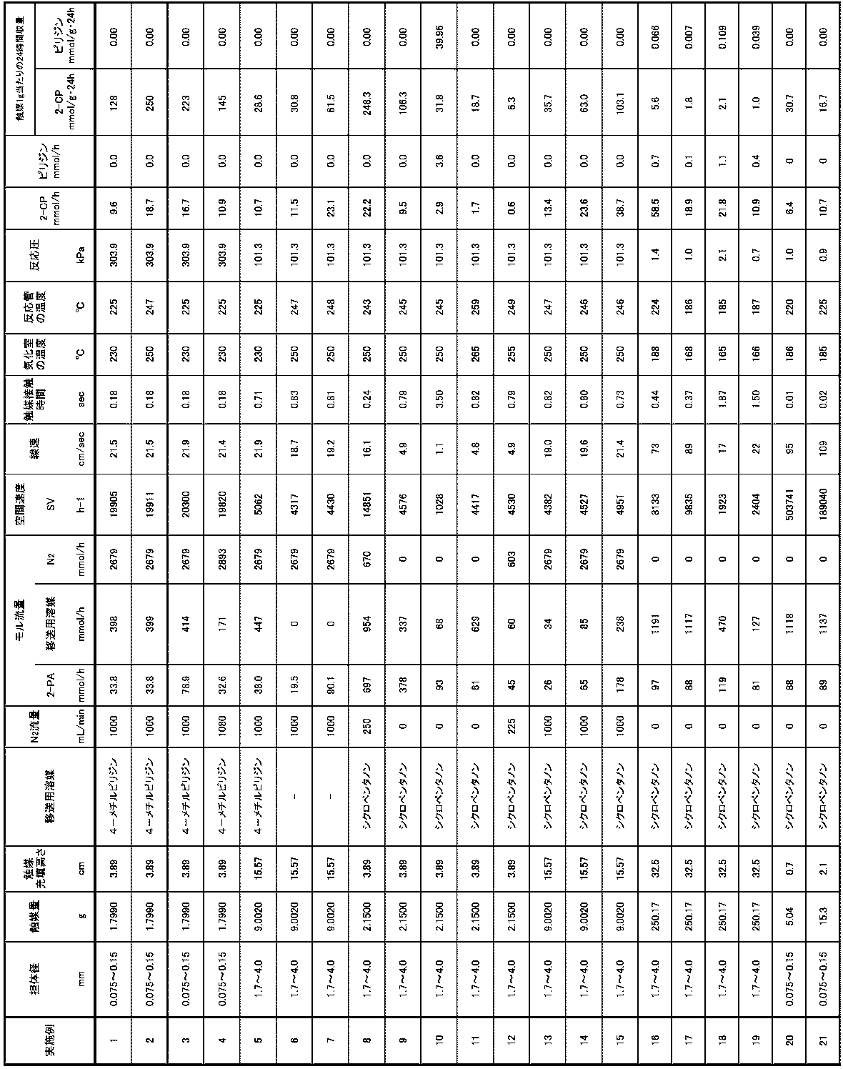
- Table 1 below shows the results of Examples 1 to 21 described above.
- Comparative Examples 1 to 9 In Comparative Examples 1 to 9, a solvent was used to remove water generated by the reaction outside the reaction system, and a dehydration reaction was performed in a liquid phase.
- reaction solution was heated at normal pressure and maintained in a boiling state, and by-product water was adsorbed on a molecular sieve and dehydrated without returning to the reactor, thereby performing a reaction.
- the reaction was started at the time when the reaction solution began to boil, and the reaction was allowed to proceed for 24 hours. After the reaction, the reaction solution was cooled to room temperature, the reaction solution was sampled, diluted 2-fold with ethanol, 1-hexanol was added as an internal standard substance, qualitative analysis was performed by GC-MS (gas chromatograph-mass spectrometer), and GC-FID was used. Quantitative analysis was performed.
- Comparative Examples 2 to 7 In Comparative Examples 2 to 7, the reaction was carried out in the same manner as in Comparative Example 1, except that the conditions were changed as shown in Table 2.
- Comparative Examples 8 and 9 In Comparative Examples 8 and 9, in addition to changing the conditions as shown in Table 2, the reaction was performed by changing the apparatus configuration and reaction conditions as described below.
- SiO 2 Carrier ACT, Q-6, manufactured by Fuji Silysia Co., Ltd., (carrier diameter: 0.075 mm or more and 0.15 mm or less)) serving as a carrier was sized to 100 mesh or less, and prefired at 700 ° C. for about 1 hour. Then, in order to support Cs as an alkali metal, the aqueous solution was adjusted using Cs 2 CO 3 (manufactured by Wako Pure Chemical Industries) so that the amount of Cs metal supported finally became 0.5 mmol / g, and SiO 2 was used. Impregnated. Then, it was dried at 110 ° C. for about 6 hours and calcined at 500 ° C. for about 3 hours to obtain a Cs 2 O / SiO 2 catalyst.
- Cs 2 CO 3 manufactured by Wako Pure Chemical Industries
- thermometer and a first air-cooled tube as a distillation column were attached to the reactor, a T-shaped tube with a thermometer attached to the upper end of the first air-cooled tube, and a second air-cooled tube attached to the T-shaped tube.
- a receiver and a vacuum pump were connected to form a reactive distillation apparatus.
- a ribbon heater was wound around the first air cooling tube so that the temperature could be adjusted.
- the cooling trap was cooled with liquid nitrogen, and vaporized pyridine could be recovered.
- the pressure of the reaction distillation apparatus was reduced to 13.3 kPa (100 Torr) by a vacuum pump, and the temperature of the first air cooling tube was 60 ° C. higher than the boiling point of water at the reaction pressure and lower than the boiling point of diphenyl ether.
- the first air-cooled tube was heated so as to obtain a reaction solution, and the reaction solution was kept boiling at 184 ° C. which was higher than the boiling point of diphenyl ether at the reaction pressure and lower than the boiling point of 2-picolinamide.
Landscapes
- Chemical & Material Sciences (AREA)
- Organic Chemistry (AREA)
- Chemical Kinetics & Catalysis (AREA)
- Inorganic Chemistry (AREA)
- Engineering & Computer Science (AREA)
- Materials Engineering (AREA)
- Organic Low-Molecular-Weight Compounds And Preparation Thereof (AREA)
- Pyridine Compounds (AREA)
- Low-Molecular Organic Synthesis Reactions Using Catalysts (AREA)
Abstract
Description
例えば、ベンゾニトリルと水との反応により生成するベンズアミドの用途は一部の医農薬中間体に限定される。このようにベンズアミドの用途は、ある程度、限定されている。よって、ベンゾニトリルを水和剤として使用する炭酸エステルの製造においては、副生するベンズアミドをベンゾニトリルに再生して再利用することが望まれ、この再生反応を選択率高く(副生成物が生じると水和剤として再利用が難しくなると考えられるため)、且つ収率高く(収率が低いとベンズアミドの残留量が多くなり、ベンゾニトリルとの分離処理量が多くなり負荷が高くなるため)行うことが課題となっていた。
しかしながら、この方法では、アミド化合物の脱水によるニトリルの生成に400時間を要し、24時間で反応が終了する炭酸エステル合成反応とバランスできない、すなわち、併用できないこと、また触媒を固液分離するため、抽出や濾過などが必要で、工程が長く煩雑であるという問題があった。
特許文献2:特開2012-162523号公報
特許文献3:WO2015/099053号公報
本発明のさらなる目的は、上記芳香族ニトリル化合物の製造方法を炭酸エステルの製造方法に適用して、効率的な炭酸エステルの製造方法を実現することである。
前記脱水反応において、気相で前記芳香族アミド化合物を触媒に接触させる接触工程を有する、芳香族ニトリル化合物の製造方法。
(2)前記触媒がアルカリ金属を含む、上記(1)に記載の芳香族ニトリル化合物の製造方法。
(3)前記芳香族アミド化合物が、少なくともヘテロアリールアミド化合物を含み、前記芳香族ニトリル化合物が、少なくともヘテロアリールニトリル化合物を含む、上記(1)
又は(2)に記載の芳香族ニトリル化合物の製造方法。
(4)前記ヘテロアリールアミド化合物が、2-ピコリンアミドを含み、前記ヘテロアリールニトリル化合物が、2-シアノピリジンを含む、上記(3)に記載の芳香族ニトリル化合物の製造方法。
(5)前記接触工程において、気化状態の不活性ガス及び/又は溶媒をさらに、前記触媒と接触させる、上記(1)~(4)のいずれか一項に記載の芳香族ニトリル化合物の製造方法。
(6)前記不活性ガスが、少なくとも窒素ガスを含む、上記(5)に記載の芳香族ニトリル化合物の製造方法。
(7)前記溶媒の常圧における沸点が、20℃以上300℃以下である、上記(5)又は(6)に記載の芳香族ニトリル化合物の製造方法。
(8)前記溶媒が、前記芳香族アミド化合物と相溶する、上記(5)~(7)のいずれか一項のいずれか一項に記載の芳香族ニトリル化合物の製造方法。
(9)前記溶媒が、ピリジン化合物及び/又は環状ケトンを含む、上記(5)~(8)のいずれか一項に記載の芳香族ニトリル化合物の製造方法。
(10)前記接触工程において、気相で芳香族アミド化合物を前記触媒と接触させる温度が、170℃以上300℃未満である、上記(1)~(9)のいずれか一項に記載の芳香族ニトリル化合物の製造方法。
(11)気相での芳香族アミド化合物の触媒接触時間が、0.001秒以上10秒未満である、上記(1)~(10)のいずれか一項に記載の芳香族ニトリル化合物の製造方法。
(12)芳香族ニトリル化合物の存在下で、アルコールと二酸化炭素とを反応させて炭酸エステルと水を生成する炭酸エステル生成反応と共に、該生成した水を該芳香族ニトリル化合物に水和させて芳香族アミド化合物を生成させる水和反応とを含む第1の反応工程と、
前記第1の反応工程の反応系から前記芳香族アミド化合物を分離した後、当該芳香族アミド化合物を脱水する脱水反応であって、前記芳香族アミド化合物を気相で触媒に接触させる接触工程を有する脱水反応により、芳香族ニトリル化合物に再生する第2の反応工程とを有し、
前記第2の反応工程で再生した前記芳香族ニトリル化合物の少なくとも一部を、前記第1の反応工程において使用する、炭酸エステルの製造方法。
(13)前記第2の反応工程において、上記(2)~(11)のいずれか一項に記載の芳香族ニトリル化合物の製造方法により前記芳香族アミド化合物から前記芳香族ニトリル化合物を製造して前記芳香族ニトリル化合物を再生させる、上記(12)に記載の炭酸エステルの製造方法。
(14)前記炭酸エステル生成反応において、酸化セリウムを含む触媒を使用する、上記(12)又は(13)に記載の炭酸エステルの製造方法。
(15)前記アルコールが、炭素数1~6のアルコールを含む、上記(12)~(14)のいずれか一項に記載の炭酸エステルの製造方法。
また、本発明によれば、上述のように芳香族ニトリル化合物を製造することにより、効率的な炭酸エステルの製造方法をも実現できる。
本発明の芳香族ニトリル化合物の製造方法においては、気相で芳香族アミド化合物、例えば、ピリジンカルボアミド(2-ピリジンカルボアミド、3-ピリジンカルボアミド、又は4-ピリジンカルボアミド)などを脱水することにより、シアノピリジンなどの芳香族ニトリル化合物へと変換する。すなわち、本発明の芳香族ニトリル化合物の製造方法は、例えば、塩基性金属酸化物を担持した触媒に、気相で芳香族アミド化合物を接触させる接触工程によって脱水反応を生じさせ、芳香族ニトリル化合物を生成するものである。

芳香族ニトリル化合物の製造方法において用いられる芳香族アミド化合物としては、ベンゼン環、ナフタレン環、アントラセン環等の芳香族炭化水素環、又は、ヘテロアリール環を有するアミド化合物が挙げられる。これらの芳香族アミド化合物のうち、ヘテロアリール環を有するもの、すなわち、ヘテロアリールアミド化合物が好適に用いられ、ヘテロアリールアミド化合物としては、ピリジン環、ピリミジン環、ピリダジン環、ピラジン環、トリアジン環、ピロール環、フラン環、チオフェン環、イミダゾール環、ピラゾール環、オキサゾール環等を有するアミド化合物が挙げられる。
ヘテロアリールアミド化合物の好ましい具体例としては、上述のピリジンカルボアミド(2-ピリジンカルボアミド、3-ピリジンカルボアミド、及び、4-ピリジンカルボアミド)等のピリジン環を有するものが挙げられる。
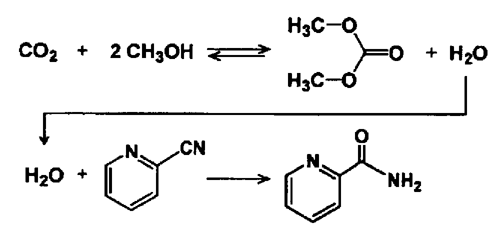
本発明の製造方法により製造される芳香族ニトリル化合物は、上記反応式からも明らかであるように、上述の芳香族アミド化合物に対応する、脱水反応の生成物である。よって、本発明の製法の対象となる芳香族ニトリル化合物の具体例として、ヘテロアリールニトリル化合物が挙げられる。ヘテロアリールニトリル化合物の好ましい具体例としては、シアノピリジン(2-シアノピリジン、3-シアノピリジン、及び、4-シアノピリジン)等のピリジン環を有するものが挙げられる。
ここで、本発明の上記脱水反応で用いられる触媒は、好ましくは、アルカリ金属(K、Li、Na、Rb、Cs)の酸化物を含む。特に、上記反応で用いられる触媒として、Na、K、Rb、およびCs(セシウム)の少なくともいずれかの酸化物を含むものを用いることが好ましい。また、上記触媒の担体としては、一般的に触媒担体となる物質を用いることができるが、様々な担体を検討した結果、好ましくは、SiO2、及び、ZrO2のいずれかを含むことが好ましい。
なお、担体径、すなわち、触媒の粒子の平均径とは、触媒の活性成分と担体とを含む触媒全体の粒子の平均径である。触媒の担体径は、ふるい分け法:JISZ8815に規定されているふるい分け試験方法通則等に基づいて測定される値である。
本発明の芳香族ニトリル化合物の製造方法においては、気体状あるいはミスト状のアミド化合物を不活性ガスと共に触媒層に流通させる気相反応を用いることが好ましく、固定床あるいは流動床の気相反応装置を適用することができる。このように、気相で芳香族アミド化合物を触媒に接触させる接触工程においては、完全に気化させた状態の芳香族アミド化合物を用いることが好ましいものの、気体中に液滴(ミスト)が部分的に含まれる状態の芳香族アミド化合物を用いても良い。
上述の脱水反応においては、芳香族アミド化合物とともに、不活性ガスを気相で触媒と接触させることが好ましい。脱水反応において用いられる不活性ガスの具体例として、窒素ガス、及び、ヘリウム、アルゴン等の希ガスが挙げられ、好ましくは、窒素ガスが用いられる。不活性ガスの流量等については後述する。
上述の脱水反応においては、溶媒を用いることもできる。特に、融点の高い芳香族アミド化合物を気化させる工程において、予め、その芳香族アミド化合物と相溶する溶媒と混合させて送液することにより、芳香族アミド化合物の析出による閉塞トラブルを防止できる。すなわち、溶媒としては、脱水反応の対象である芳香族アミド化合物と相溶するものが好ましい。芳香族アミド化合物と相溶する溶媒とは、芳香族アミド化合物に対して任意の割合で混合可能な溶媒のみならず、対象となる香族アミド化合物を所定の溶解度までしか溶解させられない溶媒であって、所定の温度において、当該溶解度の上限値以下の濃度まで芳香族アミド化合物を溶解させられる量の溶媒を含む。また、溶媒も気化させて脱水反応(接触工程)に用いることが好ましい。このように、気化させて脱水反応に用いる溶媒の沸点は、常圧において、好ましくは20℃以上300℃以下であり、より好ましくは80℃以上250℃以下であり、さらに好ましくは110℃以上200℃以下である。
溶媒としてのピリジン化合物、すなわち、ピリジン骨格を有する化合物としては、2-アルキルピリジン、3-アルキルピリジン、及び、4-アルキルピリジン等、例えば、4-メチルピリジン、及び、ピリジン等が挙げられる。特に、副生成物としてピリジンが生じ得る脱水反応において、予め好適な条件を設定した上でピリジン化合物を溶媒として用いると、主な副生成物であるピリジンの除去工程を不要にできる。
また、溶媒としてのケトン化合物としては、シクロペンタノン、シクロヘキサン等に例示される環状ケトン化合物、及び、アセトン等が挙げられる。
芳香族ニトリル化合物の製造方法は、上述のように、脱水反応において気相で芳香族アミド化合物を触媒に接触させる接触工程を有する。
接触工程において、芳香族アミド化合物等を触媒と接触させる温度は、170℃以上300℃未満であることが好ましい。上記温度は、例えば、180℃以上290℃未満あるいは190℃以上280℃未満であり、より好ましくは、210℃以上280℃未満であり、さらに好ましくは、220℃以上260℃未満である。なお、芳香族アミド化合物等を触媒と接触させる温度は、例えば、触媒を内部で固定させた反応管(反応容器)の内部の温度と等しいと考えられる。
また、接触工程における芳香族アミド化合物の触媒接触時間、及び、芳香族アミド化合物とともに、不活性ガス、溶媒等を含む場合においてはこれらのガス状組成物の混合ガスの触媒接触時間は、0.001秒以上、あるいは、0.005秒以上、例えば、0.01秒以上で、10秒未満であることが好ましい。上記触媒接触時間は、より好ましくは、0.1秒以上5秒未満であり、さらに好ましくは、0.5秒以上2秒未満である。
なお、触媒接触時間とは、触媒層を、芳香族アミド化合物のガス、又は、上記混合ガスが通過する平均時間であり、触媒接触時間(秒)=反応器内触媒層高さ(cm)÷反応器内のガス線速(cm/秒)で計算される。
接触工程における全気体成分の空間速度(SV)は、1,000~50,000(h-1)であることが好ましく、より好ましくは、1,500~30,000(h-1)であり、さらに好ましくは、2,000~25,000(h-1)である。また、減圧下で接触工程を行う場合、全気体成分の空間速度(SV)は、1,000~1,000,000(h-1)であることが好ましく、より好ましくは、1,500~700,000(h-1)であり、さらに好ましくは、1,900~504,000(h-1)である。
例えば、反応圧力は、303.9~0.7(kPa)であり、好ましくは202.6~0.9(kPa)であり、より好ましくは101.3~1.0(kPa)である。

芳香族アミド化合物から芳香族ニトリル化合物への脱水反応による再生において、気相での接触工程を設けることにより、反応速度を大幅に向上させて反応時間を大幅に短縮することができた。このことにより、芳香族アミド化合物から芳香族ニトリル化合物への脱水反応による再生速度と、芳香族ニトリル化合物を用いたCO2とアルコールからの炭酸エステル合成速度とをバランスさせることが可能になり、これらの反応を一連の商業プロセスとして成立させることが可能となった。このことから、本発明者は、この知見を炭酸エステルの製造方法に応用することで、以下に説明する炭酸エステルの製造方法に想到することができた。
本発明の炭酸エステルの製造方法における第1の反応工程は、例えばCeO2(酸化セリウム)等を含む固体触媒と、芳香族ニトリル化合物との存在下、アルコールと二酸化炭素を直接反応させて炭酸エステルを生成する反応(炭酸エステル生成反応)を含む。
ここで、アルコールとしては、第一級アルコール、第二級アルコール、第三級アルコールのうち一種又は二種以上から選ばれたいずれのアルコールも用いることができる。例えば、メタノール、エタノール、1-プロパノール、イソプロパノール、1-ブタノール、1-ペンタノール、1-ヘキサノール、1-ヘプタノール、1-オクタノール、1-ノナノール、アリルアルコール、2-メチル-1-プロパノール、シクロヘキサンメタノール、ベンジルアルコール、エチレングリコール、1,2-プロパンジオール、1,3-プロパンジオールを用いると、生成物の収率が高く、反応速度も速いので好ましい。この時、生成する炭酸エステルはそれぞれ、炭酸ジメチル、炭酸ジエチル、炭酸ジプロピル、炭酸ジイソプロピル、炭酸ジブチル、炭酸ジペンチル、炭酸ジヘキシル、炭酸ジヘプチル、炭酸ジオクチル、炭酸ジノナン、炭酸ジアリル、炭酸ジ2-メチル-プロピル、炭酸ジシクロヘキサンメチル、炭酸ジベンジル、炭酸エチレン、1,2-炭酸プロピレン、1,3-炭酸プロピレンとなる。
また、第1の反応工程において、炭素数が1~6のアルコールを用いることが好ましく、炭素数2~4のアルコールを用いることがより好ましい。特に、得られる炭酸エステルを炭酸ジアリールの原料として使用する場合には、アルコールの炭素数を上述の範囲に調整することが好ましい。
また、第1の反応工程において、一価または二価のアルコールを用いることが好ましい。
また、炭酸エステルを製造する第1の反応工程においては、CeO2及びZrO2のいずれか一方、又は双方の固体触媒を使用することが好ましい。例えば、CeO2のみ、ZrO2のみ、CeO2とZrO2の混合物、あるいはCeO2とZrO2の固溶体や複合酸化物等が好ましく、特にCeO2のみの使用が好ましい。また、CeO2とZrO2の固溶体や複合酸化物は、CeO2とZrO2の混合比が50:50を基本とするが、混合比は適宜、変更可能である。
本発明で用いる二酸化炭素は、工業ガスとして調製されたものだけでなく、各製品を製造する工場や製鉄所、発電所等からの排出ガスから分離回収したものも用いることができる。
炭酸エステル生成反応においては、生成するアミド化合物よりも沸点の高い溶媒を用いることが好ましい。より好ましくは、炭酸エステル生成反応における溶媒は、ジアルキルベンゼン、アルキルナフタレン、およびジフェニルベンゼンの少なくとも一つを含んでおり、具体例として、ジアルキルベンゼン、アルキルナフタレン、およびジフェニルベンゼン等の成分を含む、バーレルプロセス油B28AN、およびバーレルプロセス油B30(松村石油製)等が挙げられる。
反応後に、主生成物である炭酸エステル、副生成物である芳香族アミド化合物、未反応の芳香族ニトリル化合物、CeO2等の固体触媒の蒸留分離を行い、生成物を回収することができる。
次に、本発明における第2の反応工程においては、第1の反応工程で副生した芳香族アミド化合物を、好ましくは炭酸エステル生成反応後の系から分離した後、脱水反応によって、芳香族ニトリル化合物を製造する。第2の反応工程は、上述した芳香族ニトリル化合物の製造方法に相当するものである。すなわち、炭酸エステル生成のための第2の反応工程においては、上述の芳香族ニトリル化合物の製造方法の欄に記載の手法により、芳香族アミド化合物から芳香族ニトリル化合物を製造し、よって芳香族ニトリル化合物を再生させることができる。このため、第2の反応工程の詳細については、省略する。
第2の反応工程で再生された芳香族ニトリル化合物は、第1の反応工程(水和反応)に再利用することができる。
次に、以下に具体例を示して、本発明において用いられる炭酸エステルの製造装置を更に詳細に説明する。図1は好適な設備の一例である。
第1の反応工程においては、バッファータンク1に、原料である、アルコール(1-プロパノール(PrOH);液相)、2-シアノピリジン(2-CP;液相)、および、二酸化炭素(CO2;液相、昇圧ポンプを介して供給しても良い)を、原料フィード配管31、CO2回収塔 塔頂CO2移送配管(CO2回収塔の塔頂側のCO2移送配管)15、炭酸エステル回収塔 塔頂液移送配管(炭酸エステル回収塔の塔頂側の液移送配管)19、および、アミド分離塔 塔頂液移送配管(アミド分離塔の塔頂側の液移送配管)21を用いて連続的に供給する。この原料混合液を、CeO2及びZrO2のいずれか一方又は双方の固体触媒(固相)を支持材に固定した固定床流通式炭酸エステル反応器2(第1の反応部)と、バッファータンク1との間で、ポンプ(図示せず)を用いて第1及び第2の反応液循環配管11及び12を介して循環させることで、炭酸ジプロピル(DPrC)を合成する。DPrCが含まれた反応液を、バッファータンク1への原料供給量と同じ量だけ連続的に第2の反応液循環配管12から抜出して配管13により回収し、DPrC回収工程に送る。PrOHとCO2は反応液から回収して、それぞれ炭酸エステル回収塔 塔頂液移送配管19とCO2回収塔 塔頂CO2移送配管15とを介してバッファータンク1に移送することにより、再利用できる。2-シアノピリジンは反応開始時には新品を使用するが、アミド分離塔6で、2-ピコリンアミドから再生された2-シアノピリジンを分離・精製し、アミド分離塔 塔頂液移送配管21を介してバッファータンク1に移送することにより、再利用できる。
炭酸エステル反応器2における反応液温度としては、50~300℃とすることが好ましい。反応液温度が50℃未満の場合は、反応速度が低く、炭酸エステル合成反応、2-シアノピリジンによる水和反応共にほとんど進行せず、炭酸エステルの生産性が低い傾向がある。また反応液温度が300℃を超える場合は、各反応の反応速度は高くなるが、炭酸エステルの分解や変性が生じやすく、2-ピコリンアミドがアルコールと反応しやすくなるため、炭酸エステルの収率が低くなる傾向がある。反応液温度は、さらに好ましくは100~150℃である。但し、理想的な反応液温度は、固体触媒の種類や量、原料(アルコール、2-シアノピリジン)の量や比により異なると考えられるため、適宜、最適条件を設定することが望ましい。また、好ましい反応液温度が100~150℃であることから、炭酸エステル反応器の前段で、原料(アルコール、2-シアノピリジン)をスチーム等で予備加熱することが望ましい。
炭酸エステル反応器2における反応圧力としては、0.1~20MPa(絶対圧)とすることが好ましい。反応圧力が0.1MPa(絶対圧)未満の場合は、減圧装置が必要となり、設備が複雑且つコスト高になるだけでなく、減圧にするための動力エネルギーが必要となり、エネルギー効率が悪くなる。また反応圧力が20MPaを超える場合は、2-シアノピリジンによる水和反応が進行しにくくなって炭酸エステルの収率が悪くなるばかりでなく、昇圧に必要な動力エネルギーが必要となり、エネルギー効率が悪くなる。また、炭酸エステルの収率を高くする観点から、反応圧力は0.5~15MPa(絶対圧)がより好ましく、1.0~10MPa(絶対圧)がさらに好ましい。
水和反応に用いる2-シアノピリジンについては、原料のアルコールとCO2との反応で副生する水の理論モル量の0.1倍以上5倍以下のモル量を用いることが好ましく、反応前に予め反応器中に導入することが望ましい。より望ましくは、2-シアノピリジンのモル量は、原料のアルコールとCO2との反応で副生する水の理論モル量の0.2倍以上3倍以下、特に望ましくは0.3倍以上1.5倍以下である。2-シアノピリジンのモル量が少な過ぎる場合には、水和反応に寄与する2-シアノピリジンが少ないために炭酸エステルの収率が悪くなる恐れがある。一方、原料のアルコールに比べて過剰なモル量の2-シアノピリジンを導入した場合は、2-シアノピリジンの副反応が増えるため好ましくない。さらに、固体触媒に対するアルコール及び2-シアノピリジンの理想的な量は、固体触媒の種類や量、アルコールの種類や2-シアノピリジンとの比により異なると考えられるため、適宜、最適条件を設定することが望ましい。
反応生成物の分離は、好ましくは全て蒸留で行われる。炭酸エステル反応器2での反応後の反応液13は、CO2回収塔3に送られ、CO2回収塔3の塔底から、CO2回収塔 塔底液移送配管14を介して、PrOH、DPrC、2-シアノピリジン、2-ピコリンアミドの混合物を回収し、CO2回収塔3の塔頂からは、CO2回収塔 塔頂CO2移送配管15を介して、CO2を回収する。回収したCO2はバッファータンク1に送られ、炭酸エステル反応器2での反応にリサイクルする。
第2の反応工程においては、ニトリル再生気相反応器8にて、2-ピコリンアミドの脱水反応により2-シアノピリジンが生成される。
アミド分離塔6で回収された2-ピコリンアミドは、アミド分離塔 塔底液移送配管20により気化装置7に移送され、好ましくは、窒素等である不活性ガスと混合し、更にアミドの沸点近くまで加熱することにより、気体あるいは気体と液滴の混合気体とし、気化装置-ニトリル再生気相反応器連結配管22を介してニトリル再生気相反応器8に移送される。アミド化合物等を気化させる気化装置7の形式は、特に制限されず、エゼクタ式気化器、接触式気化器、バブリング装置などいずれを用いても良い。
このように、気相で2-ピコリンアミドを触媒等と接触させて、効率的に脱水反応を進行させるためには、上述の脱水反応に関する上述の様々な反応条件、又は、下記実施例の欄に記載の反応条件が適宜、採用される。
担体となるSiO2(富士シリシア化学製、CARiACT、Q-6、(担体径0.075~0.15mm))を、700℃で約1時間、予備焼成した。その後、アルカリ金属としてCsを担持するために、最終的にCs金属担持量が0.5mmol/gとなるようにCs2CO3(和光純薬工業製)を用いて水溶液を調製し、SiO2に含浸した。その後、110℃で約6時間乾燥、500℃で約3時間焼成して、Cs2O/SiO2触媒を得た。
上述の製法で製造した触媒を、内径10.7mm、長さ30cmのSUS304製の反応管40に充填した(図2参照)。さらに、反応管40の直上に、ラシヒリングを充填した内径10.7mm、長さ30cmのSUS304製の気化室42を設置した。
原料容器44に連結されている気化室42、及び、反応管40に窒素を1000mL/minの流量で流通させ、気化室42、及び、反応管40をマントルヒーター46及び48でそれぞれ、230℃に加熱した。また、窒素を供給する配管50、及び、反応管40における出側の配管は150℃で保温した。また、反応物回収のため、最初に水冷トラップ容器52、次にドライアイス/メタノール冷却トラップ容器54、及び、最終段に液体窒素冷却トラップ容器(図示せず)を設置した。
[分析条件]
(GC-FID)
Shimadzu GC-2014、カラム:TC-17(長さ30m、内径0.25mmID、液相の膜厚0.25μm)、
気化室の温度:250℃、検出器:260℃、キャリアHe:175kPa、カラム流量:2.5mL/min、スプリット比:50
温度プログラム:[70℃で5min保持]→[190℃まで昇温・12℃/min]
→[190℃で5min保持]→[250℃まで昇温・12℃/min] →[250℃で10min保持]
(反応の24時間経過後の生成物回収量mmol)/(触媒量(g))
[空間速度:SV(hr-1)]=(触媒層を通過するガス量(L・hr-1))/(触媒量(L))
ガス量:窒素、2-PA、及び、溶媒の気体体積の総和(L・hr-1)
[触媒充填高さ(反応器内触媒層高さ)]:反応管に充填した触媒の高さ(cm)
[触媒接触時間(秒)]=[触媒充填高さ(cm)]/[線速(反応器内のガス線速)(cm/秒)]
触媒の担体径 は、ふるい分け法:JIS Z 8815 に規定されている、ふるい分け試験方法通則に基づいて測定した値である。
実施例2以下については、表1に示すように条件を変更した他、実施例1と同様に反応を行った。結果を表1に示す。
なお、いずれの実施例、及び、比較例においても、触媒の活性成分はCs2Oであり、担体として富士シリシア化学株式会社製のCARiACT Q-6(主成分はSiO2)を用い、触媒の活性金属担持量(全触媒重量を基準としたときの活性種の金属換算担持量)は0.5mmol/gであった。また、いずれの実施例、及び、比較例においても、芳香族アミド化合物として2-ピコリンアミド(2-PA)を使用した。
実施例1~15と異なり、実施例16では、芳香族アミド化合物の接触反応(脱水反応)を減圧下で行った。具体的には、以下の通りである。
100gの2-ピコリンアミド(2-PA)を移送用溶媒であるシクロペンタノン(900g)に溶かし、原料容器に移し替えた。
原料容器60に連結されている反応ライン(図3に示されるエゼクター62からトラップ64まで)に窒素を1000mL/minの流量で流通させた。窒素の供給を止めた後、真空ポンプ66をトラップ64に接続し、反応系内の圧力を0.5kPaに減圧した。気化器68、及び、反応器70を電気炉(図示せず)でそれぞれ、220℃に加熱した。また、反応ラインにおける出側の配管は、リボンヒーターで(図示せず)150℃に加熱した。また、反応物回収のため、ドライアイス/メタノール冷却トラップ容器64を設置し(図3中の初留トラップ64A及び回収トラップ64B)、次に、液体窒素冷却トラップ容器(図示せず)を設置した。
反応器70に配置した触媒層(図示せず)の温度が安定した後、プランジャーポンプ72を起動し、反応を行った。触媒層内が定常状態に達したときから90分間、回収トラップ64Bで反応物を回収した。反応中、図3に示すシアノピリジン製造装置の反応系内の圧力を減圧コントローラー74とニードル弁76によって制御した。なお、触媒層内が定常状態に達するまでの間、及び、触媒層内が定常状態に達してから回収トラップ64Bで反応物を回収した後は、初留トラップ64Aで反応物を回収した。
上述の接触反応(脱水反応)の条件は、表1に示す通りである。そして反応終了後に反応物を回収し、GC-FIDで分析した。
実施例17以下については、表1に示すように条件を変更した他、実施例16と同様に反応を行った。
比較例1~9においては、反応により生成した水を反応系外に除去するために溶媒を用い、液相で脱水反応を行った。
担体となるSiO2(富士シリシア製、CARiACT、Q-6、(担体径0.075mm以上0.15mm以下))を、700℃で約1時間、予備焼成した。その後、アルカリ金属としてCsを担持するために、最終的にCs金属担持量が0.5mmol/gとなるようにCs2CO3(和光純薬工業製)を用いて水溶液を調製し、SiO2に含浸した。その後、110℃で約6時間乾燥、500℃で約3時間焼成して、Cs2O/SiO2触媒を得た。
さらに反応器に、温度計と、モレキュラーシーブ4Aを10g入れた空冷管とを取り付け、空冷管上端にはリービッヒ冷却管を取り付け、反応装置とした。
引き続き、反応液を常圧で加熱し、沸騰状態に維持し、副生水は反応器に戻すことなくモレキュラーシーブに吸着させて脱水し、反応を行った。
反応開始は、反応液が沸騰し始めた時間とし、24時間反応させた。
反応後室温まで冷却し、反応液をサンプリングし、エタノールで2倍に希釈し、内部標準物質として1-ヘキサノールを加え、GC-MS(ガスクロマトグラフ-質量分析計)で定性分析、GC-FIDで定量分析した。
比較例2~7については、表2に示すように条件を変更した他、比較例1と同様に反応を行った。
比較例8,9については、表2に示すように条件を変更した他、下記のように装置構成と反応条件を変更し、反応を行った。
さらに反応器に、温度計と、蒸留塔として第一の空冷管とを取り付け、第一の空冷管上端には温度計を取り付けたト字管を取り付け、ト字管には第二の空冷管、受器、真空ポンプを接続し、反応蒸留装置とした。なお、第一の空冷管にはリボンヒーターを巻き温度調整可能にした。また、冷却トラップは液体窒素で冷却し、気化したピリジンの回収を可能とした。
引き続き、上記反応蒸留装置の圧力を、真空ポンプで13.3kPa(100Torr)に減圧し、第一の空冷管の温度が、反応圧力における水の沸点より高く、且つ、ジフェニルエーテルの沸点より低い60℃となるように第一の空冷管を加熱し、反応液を、反応圧力におけるジフェニルエーテルの沸点以上、且つ、2-ピコリンアミドの沸点より低い184℃で沸騰状態に維持した。このように温度を調整することで、反応系中に一部気化したジフェニルエーテルを第一の空冷管で冷却して反器に戻し、副生水は反応器に戻すことなく系外に留去し、反応を行った。
反応開始は反応液が沸騰し始めた時間とし、24時間反応させた。
反応後室温まで冷却し、反応液をサンプリングし、エタノールで2倍に希釈し、内部標準物質として1-ヘキサノールを加え、GC-MS(ガスクロマトグラフ-質量分析計)で定性分析、GC-FIDで定量分析した。

2 炭酸エステル反応器(CO2、PrOH、DPrC、2-CP、2-PA、固定化触媒)
3 CO2回収塔(CO2、PrOH、DPrC、2-CP、2-PA)
4 脱水剤分離塔(PrOH、DPrC、2-CP、2-PA)
5 炭酸エステル回収塔(PrOH、DPrC)
6 アミド分離塔(2-CP、2-PA)
7 気化装置(N2、2-PA)
8 ニトリル再生気相反応器(N2、H2O、2-CP、2-PA、触媒)
9 H2O分離装置(N2、H2O、2-CP、2-PA)
10 N2回収装置(N2、H2O)
11 第1の反応液循環配管(CO2、PrOH、DPrC、2-CP、2-PA)
12 第2の反応液循環配管(CO2、PrOH、DPrC、2-CP、2-PA)
13 反応液抜出し配管(CO2、PrOH、DPrC、2-CP、2-PA)
14 CO2回収塔 塔底液移送配管(PrOH、DPrC、2-CP、2-PA)
15 CO2回収塔 塔頂CO2移送配管(CO2)
16 脱水剤分離塔 塔底液移送配管(2-CP、2-PA)
17 脱水剤分離塔 塔頂液移送配管(PrOH、DPrC)
18 炭酸エステル回収塔 塔底液移送配管(DPrC)
19 炭酸エステル回収塔 塔頂液移送配管(PrOH)
20 アミド分離塔 塔底液移送配管(2-PA)
21 アミド分離塔 塔頂液移送配管(2-CP)
22 気化装置-ニトリル再生気相反応器 連結配管(N2、2-PA)
23 気相反応生成物移送配管(N2、H2O、2-CP、2-PA)
24 H2O分離装置 高沸移送配管(2-CP、2-PA)
25 H2O分離装置 軽沸移送配管(N2、H2O)
26 N2回収装置 水分移送配管(H2O)
27 N2回収装置 N2移送配管(N2)
31 原料フィード配管(CO2、PrOH)
40 反応管
42 気化室
44 原料容器
46,48 マントルヒーター
50 窒素ガス供給配管
52 水冷トラップ容器
54 ドライアイス/メタノール冷却トラップ容器
56 プランジャーポンプ
58 圧力リミッター
60 原料容器
62 エゼクター
64 トラップ
64A 初留トラップ
64B 回収トラップ
66 真空ポンプ
68 気化器
70 反応器
72 プランジャーポンプ
74 減圧コントローラー
76 ニードル弁
Claims (15)
- 芳香族アミド化合物を脱水する脱水反応を含む芳香族ニトリル化合物の製造方法であって、
前記脱水反応において、気相で前記芳香族アミド化合物を触媒に接触させる接触工程を有する、芳香族ニトリル化合物の製造方法。 - 前記触媒がアルカリ金属を含む、請求項1に記載の芳香族ニトリル化合物の製造方法。
- 前記芳香族アミド化合物が、少なくともヘテロアリールアミド化合物を含み、前記芳香族ニトリル化合物が、少なくともヘテロアリールニトリル化合物を含む、請求項1又は2に記載の芳香族ニトリル化合物の製造方法。
- 前記ヘテロアリールアミド化合物が、2-ピコリンアミドを含み、前記ヘテロアリールニトリル化合物が、2-シアノピリジンを含む、請求項3に記載の芳香族ニトリル化合物の製造方法。
- 前記接触工程において、気化状態の不活性ガス及び/又は溶媒をさらに、前記触媒と接触させる、請求項1~4のいずれか一項に記載の芳香族ニトリル化合物の製造方法。
- 前記不活性ガスが、少なくとも窒素ガスを含む、請求項5に記載の芳香族ニトリル化合物の製造方法。
- 前記溶媒の常圧における沸点が、20℃以上300℃以下である、請求項5又は6に記載の芳香族ニトリル化合物の製造方法。
- 前記溶媒が、前記芳香族アミド化合物と相溶する、請求項5~7のいずれか一項に記載の芳香族ニトリル化合物の製造方法。
- 前記溶媒が、ピリジン化合物及び/又はケトン化合物を含む、請求項5~8のいずれか一項に記載の芳香族ニトリル化合物の製造方法。
- 前記接触工程において、気相で前記芳香族アミド化合物を前記触媒と接触させる温度が、170℃以上300℃未満である、請求項1~9のいずれか一項に記載の芳香族ニトリル化合物の製造方法。
- 気相での前記芳香族アミド化合物の触媒接触時間が、0.001秒以上10秒未満である、請求項1~10のいずれか一項に記載の芳香族ニトリル化合物の製造方法。
- 芳香族ニトリル化合物の存在下で、アルコールと二酸化炭素とを反応させて炭酸エステルと水を生成する炭酸エステル生成反応と共に、該生成した水を該芳香族ニトリル化合物に水和させて芳香族アミド化合物を生成させる水和反応とを含む第1の反応工程と、
前記第1の反応工程の反応系から前記芳香族アミド化合物を分離した後、当該芳香族アミド化合物を脱水する脱水反応であって、前記芳香族アミド化合物を気相で触媒に接触させる接触工程を有する脱水反応により、芳香族ニトリル化合物に再生する第2の反応工程とを有し、
前記第2の反応工程で再生した前記芳香族ニトリル化合物の少なくとも一部を、前記第1の反応工程において使用する、炭酸エステルの製造方法。 - 前記第2の反応工程において、請求項2~11のいずれか一項に記載の芳香族ニトリル化合物の製造方法により前記芳香族アミド化合物から前記芳香族ニトリル化合物を製造して前記芳香族ニトリル化合物を再生させる、請求項12に記載の炭酸エステルの製造方法。
- 前記炭酸エステル生成反応において、酸化セリウムを含む触媒を使用する、請求項12又は13に記載の炭酸エステルの製造方法。
- 前記アルコールが、炭素数1~6のアルコールを含む、請求項12~14のいずれか一項に記載の炭酸エステルの製造方法。
Priority Applications (9)
| Application Number | Priority Date | Filing Date | Title |
|---|---|---|---|
| EP23156761.1A EP4201925B1 (en) | 2018-07-27 | 2019-07-25 | Method for producing aromatic nitrile compound and method for producing carbonate ester |
| KR1020217005266A KR102733207B1 (ko) | 2018-07-27 | 2019-07-25 | 방향족 나이트릴 화합물의 제조 방법, 및 탄산 에스터의 제조 방법 |
| JP2020532459A JP7367676B2 (ja) | 2018-07-27 | 2019-07-25 | 芳香族ニトリル化合物の製造方法、及び炭酸エステルの製造方法 |
| SG11202012997YA SG11202012997YA (en) | 2018-07-27 | 2019-07-25 | Method for producing aromatic nitrile compound and method for producing carbonate ester |
| US17/261,612 US11673856B2 (en) | 2018-07-27 | 2019-07-25 | Method for producing aromatic nitrile compound and method for producing carbonate ester |
| CN201980049503.9A CN112469700A (zh) | 2018-07-27 | 2019-07-25 | 芳香族腈化合物的制造方法和碳酸酯的制造方法 |
| EP19840326.3A EP3831813B1 (en) | 2018-07-27 | 2019-07-25 | Method for producing aromatic nitrile compound and method for producing carbonate ester |
| ES19840326T ES2946440T3 (es) | 2018-07-27 | 2019-07-25 | Método para producir compuesto de nitrilo aromático y método para producir éster carbonato |
| US18/140,333 US12202786B2 (en) | 2018-07-27 | 2023-04-27 | Method for producing aromatic nitrile compound and method for producing carbonate ester |
Applications Claiming Priority (2)
| Application Number | Priority Date | Filing Date | Title |
|---|---|---|---|
| JP2018-141487 | 2018-07-27 | ||
| JP2018141487 | 2018-07-27 |
Related Child Applications (2)
| Application Number | Title | Priority Date | Filing Date |
|---|---|---|---|
| US17/261,612 A-371-Of-International US11673856B2 (en) | 2018-07-27 | 2019-07-25 | Method for producing aromatic nitrile compound and method for producing carbonate ester |
| US18/140,333 Division US12202786B2 (en) | 2018-07-27 | 2023-04-27 | Method for producing aromatic nitrile compound and method for producing carbonate ester |
Publications (1)
| Publication Number | Publication Date |
|---|---|
| WO2020022416A1 true WO2020022416A1 (ja) | 2020-01-30 |
Family
ID=69180301
Family Applications (1)
| Application Number | Title | Priority Date | Filing Date |
|---|---|---|---|
| PCT/JP2019/029164 Ceased WO2020022416A1 (ja) | 2018-07-27 | 2019-07-25 | 芳香族ニトリル化合物の製造方法、及び炭酸エステルの製造方法 |
Country Status (10)
| Country | Link |
|---|---|
| US (2) | US11673856B2 (ja) |
| EP (2) | EP3831813B1 (ja) |
| JP (1) | JP7367676B2 (ja) |
| KR (1) | KR102733207B1 (ja) |
| CN (1) | CN112469700A (ja) |
| ES (2) | ES3010305T3 (ja) |
| SA (1) | SA521421069B1 (ja) |
| SG (1) | SG11202012997YA (ja) |
| TW (1) | TWI828726B (ja) |
| WO (1) | WO2020022416A1 (ja) |
Cited By (3)
| Publication number | Priority date | Publication date | Assignee | Title |
|---|---|---|---|---|
| CN112495362A (zh) * | 2020-12-21 | 2021-03-16 | 中国科学院山西煤炭化学研究所 | 一种适用于一级酰胺化合物分子内脱水制备腈类的催化剂及其制备方法和应用 |
| WO2025009575A1 (ja) | 2023-07-04 | 2025-01-09 | 三菱瓦斯化学株式会社 | フロニトリル化合物の製造方法、及び炭酸エステルの製造方法 |
| WO2025009574A1 (ja) | 2023-07-04 | 2025-01-09 | 三菱瓦斯化学株式会社 | 芳香族ニトリル化合物の製造方法、及び炭酸エステルの製造方法 |
Families Citing this family (2)
| Publication number | Priority date | Publication date | Assignee | Title |
|---|---|---|---|---|
| EP3822251A4 (en) * | 2018-07-10 | 2021-10-13 | Nippon Steel Corporation | PROCESS FOR THE PREPARATION OF CARBON ESTERS AND CATALYTIC STRUCTURE FOR THE PREPARATION OF CARBON ESTERS |
| CN116396216A (zh) * | 2023-04-10 | 2023-07-07 | 浙江大学 | 一种二氧化铈催化酰胺脱水制腈的方法及其应用 |
Citations (7)
| Publication number | Priority date | Publication date | Assignee | Title |
|---|---|---|---|---|
| JPH04321672A (ja) * | 1990-12-21 | 1992-11-11 | F Hoffmann La Roche Ag | 5−シアノ−4−低級アルキル−オキサゾール類の製造方法 |
| JPH093030A (ja) * | 1995-06-21 | 1997-01-07 | Huels Ag | 2−ヒドロキシベンゾニトリルの製造法 |
| JP2010077113A (ja) | 2008-08-27 | 2010-04-08 | Nippon Steel Corp | 炭酸エステルの製造方法 |
| JP2012162523A (ja) | 2011-01-20 | 2012-08-30 | Nippon Steel Corp | 炭酸エステルの製造方法 |
| WO2015099053A1 (ja) | 2013-12-27 | 2015-07-02 | 新日鐵住金株式会社 | シアノピリジンの製造方法、ベンゾニトリルの製造方法、炭酸エステルの製造方法、及び炭酸エステルの製造装置 |
| JP2016216361A (ja) * | 2014-03-04 | 2016-12-22 | 新日鐵住金株式会社 | 炭酸エステルの製造方法及び製造装置 |
| WO2018116775A1 (ja) * | 2016-12-21 | 2018-06-28 | 三菱瓦斯化学株式会社 | 芳香族ニトリル化合物の製造方法、及び炭酸エステルの製造方法 |
Family Cites Families (6)
| Publication number | Priority date | Publication date | Assignee | Title |
|---|---|---|---|---|
| DE1279020B (de) | 1966-08-04 | 1968-10-03 | Hoechst Ag | Verfahren zur kontinuierlichen Herstellung von aliphatischen oder aromatischen Nitrilen aus Carbonsaeureestern |
| US4026901A (en) | 1975-04-30 | 1977-05-31 | Hoffmann-La Roche Inc. | Conversion of 4-lower alkyloxazole-5-carboxamide to 4-lower alkyl-5-cyanooxazoles |
| DE3923979A1 (de) * | 1989-07-20 | 1991-01-24 | Merck Patent Gmbh | Verfahren zur herstellung von aromatischen nitrilen |
| CN109311815B (zh) * | 2016-06-22 | 2022-11-18 | 三菱瓦斯化学株式会社 | 芳香族腈化合物的制造方法以及碳酸酯的制造方法 |
| SG11202001689XA (en) | 2017-09-29 | 2020-04-29 | Mitsubishi Gas Chemical Co | Method for regenerating catalyst and method for producing carbonate ester |
| CN111601785B (zh) | 2018-01-10 | 2023-03-28 | 三菱瓦斯化学株式会社 | 碳酸酯的制造方法 |
-
2019
- 2019-07-25 ES ES23156761T patent/ES3010305T3/es active Active
- 2019-07-25 US US17/261,612 patent/US11673856B2/en active Active
- 2019-07-25 KR KR1020217005266A patent/KR102733207B1/ko active Active
- 2019-07-25 JP JP2020532459A patent/JP7367676B2/ja active Active
- 2019-07-25 ES ES19840326T patent/ES2946440T3/es active Active
- 2019-07-25 WO PCT/JP2019/029164 patent/WO2020022416A1/ja not_active Ceased
- 2019-07-25 EP EP19840326.3A patent/EP3831813B1/en active Active
- 2019-07-25 EP EP23156761.1A patent/EP4201925B1/en active Active
- 2019-07-25 SG SG11202012997YA patent/SG11202012997YA/en unknown
- 2019-07-25 TW TW108126302A patent/TWI828726B/zh active
- 2019-07-25 CN CN201980049503.9A patent/CN112469700A/zh active Pending
-
2021
- 2021-01-20 SA SA521421069A patent/SA521421069B1/ar unknown
-
2023
- 2023-04-27 US US18/140,333 patent/US12202786B2/en active Active
Patent Citations (7)
| Publication number | Priority date | Publication date | Assignee | Title |
|---|---|---|---|---|
| JPH04321672A (ja) * | 1990-12-21 | 1992-11-11 | F Hoffmann La Roche Ag | 5−シアノ−4−低級アルキル−オキサゾール類の製造方法 |
| JPH093030A (ja) * | 1995-06-21 | 1997-01-07 | Huels Ag | 2−ヒドロキシベンゾニトリルの製造法 |
| JP2010077113A (ja) | 2008-08-27 | 2010-04-08 | Nippon Steel Corp | 炭酸エステルの製造方法 |
| JP2012162523A (ja) | 2011-01-20 | 2012-08-30 | Nippon Steel Corp | 炭酸エステルの製造方法 |
| WO2015099053A1 (ja) | 2013-12-27 | 2015-07-02 | 新日鐵住金株式会社 | シアノピリジンの製造方法、ベンゾニトリルの製造方法、炭酸エステルの製造方法、及び炭酸エステルの製造装置 |
| JP2016216361A (ja) * | 2014-03-04 | 2016-12-22 | 新日鐵住金株式会社 | 炭酸エステルの製造方法及び製造装置 |
| WO2018116775A1 (ja) * | 2016-12-21 | 2018-06-28 | 三菱瓦斯化学株式会社 | 芳香族ニトリル化合物の製造方法、及び炭酸エステルの製造方法 |
Cited By (3)
| Publication number | Priority date | Publication date | Assignee | Title |
|---|---|---|---|---|
| CN112495362A (zh) * | 2020-12-21 | 2021-03-16 | 中国科学院山西煤炭化学研究所 | 一种适用于一级酰胺化合物分子内脱水制备腈类的催化剂及其制备方法和应用 |
| WO2025009575A1 (ja) | 2023-07-04 | 2025-01-09 | 三菱瓦斯化学株式会社 | フロニトリル化合物の製造方法、及び炭酸エステルの製造方法 |
| WO2025009574A1 (ja) | 2023-07-04 | 2025-01-09 | 三菱瓦斯化学株式会社 | 芳香族ニトリル化合物の製造方法、及び炭酸エステルの製造方法 |
Also Published As
| Publication number | Publication date |
|---|---|
| TW202019868A (zh) | 2020-06-01 |
| SG11202012997YA (en) | 2021-02-25 |
| EP3831813A1 (en) | 2021-06-09 |
| CN112469700A (zh) | 2021-03-09 |
| EP4201925A1 (en) | 2023-06-28 |
| US11673856B2 (en) | 2023-06-13 |
| JP7367676B2 (ja) | 2023-10-24 |
| KR102733207B1 (ko) | 2024-11-21 |
| US12202786B2 (en) | 2025-01-21 |
| EP4201925B1 (en) | 2024-11-20 |
| TWI828726B (zh) | 2024-01-11 |
| US20210261496A1 (en) | 2021-08-26 |
| EP3831813B1 (en) | 2023-05-03 |
| ES2946440T3 (es) | 2023-07-18 |
| KR20210040392A (ko) | 2021-04-13 |
| ES3010305T3 (en) | 2025-04-02 |
| US20230348367A1 (en) | 2023-11-02 |
| JPWO2020022416A1 (ja) | 2021-08-02 |
| EP3831813A4 (en) | 2021-06-09 |
| SA521421069B1 (ar) | 2023-06-15 |
Similar Documents
| Publication | Publication Date | Title |
|---|---|---|
| JP7367676B2 (ja) | 芳香族ニトリル化合物の製造方法、及び炭酸エステルの製造方法 | |
| JP7092305B2 (ja) | 芳香族ニトリル化合物の製造方法、及び炭酸エステルの製造方法 | |
| CN111601785B (zh) | 碳酸酯的制造方法 | |
| JP7828944B2 (ja) | 2-フロニトリルの製造方法、及び炭酸エステルの製造方法 | |
| KR102513071B1 (ko) | 방향족 나이트릴 화합물의 제조 방법 및 탄산 에스터의 제조 방법 | |
| JP2016216361A (ja) | 炭酸エステルの製造方法及び製造装置 | |
| RU2804510C2 (ru) | Способ получения ароматического нитрильного соединения и способ получения карбонатного эфира | |
| WO2025009574A1 (ja) | 芳香族ニトリル化合物の製造方法、及び炭酸エステルの製造方法 | |
| WO2025009575A1 (ja) | フロニトリル化合物の製造方法、及び炭酸エステルの製造方法 | |
| RU2842337C1 (ru) | Способ получения 2-фуронитрила и способ получения карбонатного сложного эфира |
Legal Events
| Date | Code | Title | Description |
|---|---|---|---|
| 121 | Ep: the epo has been informed by wipo that ep was designated in this application |
Ref document number: 19840326 Country of ref document: EP Kind code of ref document: A1 |
|
| ENP | Entry into the national phase |
Ref document number: 2020532459 Country of ref document: JP Kind code of ref document: A |
|
| NENP | Non-entry into the national phase |
Ref country code: DE |
|
| ENP | Entry into the national phase |
Ref document number: 2019840326 Country of ref document: EP Effective date: 20210301 |
|
| WWG | Wipo information: grant in national office |
Ref document number: 11202012997Y Country of ref document: SG |
|
| WWP | Wipo information: published in national office |
Ref document number: 11202012997Y Country of ref document: SG |