WO2020022062A1 - 内燃機関 - Google Patents
内燃機関 Download PDFInfo
- Publication number
- WO2020022062A1 WO2020022062A1 PCT/JP2019/027296 JP2019027296W WO2020022062A1 WO 2020022062 A1 WO2020022062 A1 WO 2020022062A1 JP 2019027296 W JP2019027296 W JP 2019027296W WO 2020022062 A1 WO2020022062 A1 WO 2020022062A1
- Authority
- WO
- WIPO (PCT)
- Prior art keywords
- internal combustion
- combustion engine
- temperature
- timing
- combustion chamber
- Prior art date
- Legal status (The legal status is an assumption and is not a legal conclusion. Google has not performed a legal analysis and makes no representation as to the accuracy of the status listed.)
- Ceased
Links
Images






Classifications
-
- F—MECHANICAL ENGINEERING; LIGHTING; HEATING; WEAPONS; BLASTING
- F02—COMBUSTION ENGINES; HOT-GAS OR COMBUSTION-PRODUCT ENGINE PLANTS
- F02D—CONTROLLING COMBUSTION ENGINES
- F02D41/00—Electrical control of supply of combustible mixture or its constituents
- F02D41/02—Circuit arrangements for generating control signals
- F02D41/04—Introducing corrections for particular operating conditions
- F02D41/06—Introducing corrections for particular operating conditions for engine starting or warming up
- F02D41/062—Introducing corrections for particular operating conditions for engine starting or warming up for starting
- F02D41/064—Introducing corrections for particular operating conditions for engine starting or warming up for starting at cold start
-
- F—MECHANICAL ENGINEERING; LIGHTING; HEATING; WEAPONS; BLASTING
- F02—COMBUSTION ENGINES; HOT-GAS OR COMBUSTION-PRODUCT ENGINE PLANTS
- F02D—CONTROLLING COMBUSTION ENGINES
- F02D13/00—Controlling the engine output power by varying inlet or exhaust valve operating characteristics, e.g. timing
- F02D13/02—Controlling the engine output power by varying inlet or exhaust valve operating characteristics, e.g. timing during engine operation
- F02D13/0223—Variable control of the intake valves only
- F02D13/0234—Variable control of the intake valves only changing the valve timing only
-
- F—MECHANICAL ENGINEERING; LIGHTING; HEATING; WEAPONS; BLASTING
- F02—COMBUSTION ENGINES; HOT-GAS OR COMBUSTION-PRODUCT ENGINE PLANTS
- F02D—CONTROLLING COMBUSTION ENGINES
- F02D13/00—Controlling the engine output power by varying inlet or exhaust valve operating characteristics, e.g. timing
- F02D13/02—Controlling the engine output power by varying inlet or exhaust valve operating characteristics, e.g. timing during engine operation
- F02D13/0203—Variable control of intake and exhaust valves
- F02D13/0215—Variable control of intake and exhaust valves changing the valve timing only
- F02D13/0219—Variable control of intake and exhaust valves changing the valve timing only by shifting the phase, i.e. the opening periods of the valves are constant
-
- F—MECHANICAL ENGINEERING; LIGHTING; HEATING; WEAPONS; BLASTING
- F02—COMBUSTION ENGINES; HOT-GAS OR COMBUSTION-PRODUCT ENGINE PLANTS
- F02D—CONTROLLING COMBUSTION ENGINES
- F02D29/00—Controlling engines, such controlling being peculiar to the devices driven thereby, the devices being other than parts or accessories essential to engine operation, e.g. controlling of engines by signals external thereto
- F02D29/02—Controlling engines, such controlling being peculiar to the devices driven thereby, the devices being other than parts or accessories essential to engine operation, e.g. controlling of engines by signals external thereto peculiar to engines driving vehicles; peculiar to engines driving variable pitch propellers
-
- F—MECHANICAL ENGINEERING; LIGHTING; HEATING; WEAPONS; BLASTING
- F02—COMBUSTION ENGINES; HOT-GAS OR COMBUSTION-PRODUCT ENGINE PLANTS
- F02D—CONTROLLING COMBUSTION ENGINES
- F02D31/00—Use of speed-sensing governors to control combustion engines, not otherwise provided for
- F02D31/001—Electric control of rotation speed
- F02D31/002—Electric control of rotation speed controlling air supply
-
- F—MECHANICAL ENGINEERING; LIGHTING; HEATING; WEAPONS; BLASTING
- F02—COMBUSTION ENGINES; HOT-GAS OR COMBUSTION-PRODUCT ENGINE PLANTS
- F02D—CONTROLLING COMBUSTION ENGINES
- F02D31/00—Use of speed-sensing governors to control combustion engines, not otherwise provided for
- F02D31/001—Electric control of rotation speed
- F02D31/007—Electric control of rotation speed controlling fuel supply
-
- F—MECHANICAL ENGINEERING; LIGHTING; HEATING; WEAPONS; BLASTING
- F02—COMBUSTION ENGINES; HOT-GAS OR COMBUSTION-PRODUCT ENGINE PLANTS
- F02D—CONTROLLING COMBUSTION ENGINES
- F02D35/00—Controlling engines, dependent on conditions exterior or interior to engines, not otherwise provided for
- F02D35/02—Controlling engines, dependent on conditions exterior or interior to engines, not otherwise provided for on interior conditions
- F02D35/025—Controlling engines, dependent on conditions exterior or interior to engines, not otherwise provided for on interior conditions by determining temperatures inside the cylinder, e.g. combustion temperatures
-
- F—MECHANICAL ENGINEERING; LIGHTING; HEATING; WEAPONS; BLASTING
- F02—COMBUSTION ENGINES; HOT-GAS OR COMBUSTION-PRODUCT ENGINE PLANTS
- F02D—CONTROLLING COMBUSTION ENGINES
- F02D41/00—Electrical control of supply of combustible mixture or its constituents
- F02D41/0002—Controlling intake air
-
- F—MECHANICAL ENGINEERING; LIGHTING; HEATING; WEAPONS; BLASTING
- F02—COMBUSTION ENGINES; HOT-GAS OR COMBUSTION-PRODUCT ENGINE PLANTS
- F02D—CONTROLLING COMBUSTION ENGINES
- F02D41/00—Electrical control of supply of combustible mixture or its constituents
- F02D41/0097—Electrical control of supply of combustible mixture or its constituents using means for generating speed signals
-
- F—MECHANICAL ENGINEERING; LIGHTING; HEATING; WEAPONS; BLASTING
- F02—COMBUSTION ENGINES; HOT-GAS OR COMBUSTION-PRODUCT ENGINE PLANTS
- F02D—CONTROLLING COMBUSTION ENGINES
- F02D41/00—Electrical control of supply of combustible mixture or its constituents
- F02D41/02—Circuit arrangements for generating control signals
- F02D41/04—Introducing corrections for particular operating conditions
- F02D41/06—Introducing corrections for particular operating conditions for engine starting or warming up
- F02D41/062—Introducing corrections for particular operating conditions for engine starting or warming up for starting
-
- F—MECHANICAL ENGINEERING; LIGHTING; HEATING; WEAPONS; BLASTING
- F02—COMBUSTION ENGINES; HOT-GAS OR COMBUSTION-PRODUCT ENGINE PLANTS
- F02D—CONTROLLING COMBUSTION ENGINES
- F02D41/00—Electrical control of supply of combustible mixture or its constituents
- F02D41/30—Controlling fuel injection
- F02D41/38—Controlling fuel injection of the high pressure type
-
- F—MECHANICAL ENGINEERING; LIGHTING; HEATING; WEAPONS; BLASTING
- F02—COMBUSTION ENGINES; HOT-GAS OR COMBUSTION-PRODUCT ENGINE PLANTS
- F02D—CONTROLLING COMBUSTION ENGINES
- F02D41/00—Electrical control of supply of combustible mixture or its constituents
- F02D41/0002—Controlling intake air
- F02D2041/001—Controlling intake air for engines with variable valve actuation
-
- F—MECHANICAL ENGINEERING; LIGHTING; HEATING; WEAPONS; BLASTING
- F02—COMBUSTION ENGINES; HOT-GAS OR COMBUSTION-PRODUCT ENGINE PLANTS
- F02D—CONTROLLING COMBUSTION ENGINES
- F02D2200/00—Input parameters for engine control
- F02D2200/02—Input parameters for engine control the parameters being related to the engine
- F02D2200/04—Engine intake system parameters
- F02D2200/0414—Air temperature
-
- F—MECHANICAL ENGINEERING; LIGHTING; HEATING; WEAPONS; BLASTING
- F02—COMBUSTION ENGINES; HOT-GAS OR COMBUSTION-PRODUCT ENGINE PLANTS
- F02D—CONTROLLING COMBUSTION ENGINES
- F02D2200/00—Input parameters for engine control
- F02D2200/02—Input parameters for engine control the parameters being related to the engine
- F02D2200/10—Parameters related to the engine output, e.g. engine torque or engine speed
- F02D2200/101—Engine speed
-
- F—MECHANICAL ENGINEERING; LIGHTING; HEATING; WEAPONS; BLASTING
- F02—COMBUSTION ENGINES; HOT-GAS OR COMBUSTION-PRODUCT ENGINE PLANTS
- F02D—CONTROLLING COMBUSTION ENGINES
- F02D2200/00—Input parameters for engine control
- F02D2200/70—Input parameters for engine control said parameters being related to the vehicle exterior
-
- F—MECHANICAL ENGINEERING; LIGHTING; HEATING; WEAPONS; BLASTING
- F02—COMBUSTION ENGINES; HOT-GAS OR COMBUSTION-PRODUCT ENGINE PLANTS
- F02P—IGNITION, OTHER THAN COMPRESSION IGNITION, FOR INTERNAL-COMBUSTION ENGINES; TESTING OF IGNITION TIMING IN COMPRESSION-IGNITION ENGINES
- F02P5/00—Advancing or retarding ignition; Control therefor
- F02P5/04—Advancing or retarding ignition; Control therefor automatically, as a function of the working conditions of the engine or vehicle or of the atmospheric conditions
- F02P5/045—Advancing or retarding ignition; Control therefor automatically, as a function of the working conditions of the engine or vehicle or of the atmospheric conditions combined with electronic control of other engine functions, e.g. fuel injection
-
- F—MECHANICAL ENGINEERING; LIGHTING; HEATING; WEAPONS; BLASTING
- F02—COMBUSTION ENGINES; HOT-GAS OR COMBUSTION-PRODUCT ENGINE PLANTS
- F02P—IGNITION, OTHER THAN COMPRESSION IGNITION, FOR INTERNAL-COMBUSTION ENGINES; TESTING OF IGNITION TIMING IN COMPRESSION-IGNITION ENGINES
- F02P5/00—Advancing or retarding ignition; Control therefor
- F02P5/04—Advancing or retarding ignition; Control therefor automatically, as a function of the working conditions of the engine or vehicle or of the atmospheric conditions
- F02P5/145—Advancing or retarding ignition; Control therefor automatically, as a function of the working conditions of the engine or vehicle or of the atmospheric conditions using electrical means
- F02P5/15—Digital data processing
- F02P5/1502—Digital data processing using one central computing unit
- F02P5/1506—Digital data processing using one central computing unit with particular means during starting
-
- Y—GENERAL TAGGING OF NEW TECHNOLOGICAL DEVELOPMENTS; GENERAL TAGGING OF CROSS-SECTIONAL TECHNOLOGIES SPANNING OVER SEVERAL SECTIONS OF THE IPC; TECHNICAL SUBJECTS COVERED BY FORMER USPC CROSS-REFERENCE ART COLLECTIONS [XRACs] AND DIGESTS
- Y02—TECHNOLOGIES OR APPLICATIONS FOR MITIGATION OR ADAPTATION AGAINST CLIMATE CHANGE
- Y02T—CLIMATE CHANGE MITIGATION TECHNOLOGIES RELATED TO TRANSPORTATION
- Y02T10/00—Road transport of goods or passengers
- Y02T10/10—Internal combustion engine [ICE] based vehicles
- Y02T10/12—Improving ICE efficiencies
-
- Y—GENERAL TAGGING OF NEW TECHNOLOGICAL DEVELOPMENTS; GENERAL TAGGING OF CROSS-SECTIONAL TECHNOLOGIES SPANNING OVER SEVERAL SECTIONS OF THE IPC; TECHNICAL SUBJECTS COVERED BY FORMER USPC CROSS-REFERENCE ART COLLECTIONS [XRACs] AND DIGESTS
- Y02—TECHNOLOGIES OR APPLICATIONS FOR MITIGATION OR ADAPTATION AGAINST CLIMATE CHANGE
- Y02T—CLIMATE CHANGE MITIGATION TECHNOLOGIES RELATED TO TRANSPORTATION
- Y02T10/00—Road transport of goods or passengers
- Y02T10/10—Internal combustion engine [ICE] based vehicles
- Y02T10/40—Engine management systems
Definitions
- the present invention relates to an internal combustion engine, and more particularly, to an internal combustion engine including a control unit that performs control for warming up the combustion chamber until the first ignition is performed.
- Japanese Patent Application Laid-Open No. 2009-299538 discloses an engine including a control device for performing control for warming up a combustion chamber until the first ignition is performed by motoring, and a variable valve timing mechanism.
- the control device is configured such that the variable valve timing mechanism uniformly sets the timing for closing the intake valve to be more advanced than the reference timing (during normal operation) during motoring.
- the engine compresses the intake air to increase the temperature in the cylinder by closing the intake valve early on the bottom dead center side and retaining a large amount of intake air in the cylinder.
- the temperature in the cylinder increases, the atomization of the fuel is effectively performed, so that the exhaust gas immediately after the first explosion is reduced.
- An advantage of some aspects of the invention is to perform appropriate control for reducing exhaust gas according to the environmental temperature of an internal combustion engine. It is to provide a possible internal combustion engine.
- an internal combustion engine includes an internal combustion engine main body provided with an intake valve and an exhaust valve, and an internal combustion engine main body based on an environmental temperature at the start of starting of the internal combustion engine main body. Is controlled to drive the internal combustion engine main body at the set predetermined rotational speed during a period from the time when fuel is supplied to the combustion chamber of the internal combustion engine main body and the first ignition is performed by setting the rotational speed of the internal combustion engine main body to the predetermined rotational speed.
- the rotation speed of the internal combustion engine main body is set to a predetermined rotation speed based on the environmental temperature at the start of the start of the internal combustion engine main body.
- a control unit is provided for performing control for driving the internal combustion engine main body at a set predetermined number of revolutions during a period from when fuel is supplied to the combustion chamber to first ignition.
- the internal combustion engine according to the above aspect further includes a variable valve mechanism capable of adjusting the opening / closing timing of the intake valve by control of the control unit, wherein the control unit is capable of introducing the most outside air based on a predetermined rotation speed. It is configured to perform timing control for setting a proper intake valve closing timing.
- the control unit continues the timing control until the first cycle when supplying fuel to the combustion chamber and performing the first ignition, and in the second and subsequent cycles, the variable valve control is preferably performed.
- the mechanism is configured to return to the valve timing of the intake valve during steady operation.
- the timing control can be continued for a longer time than in the case where the timing control is terminated only in the initial part of the period before the first ignition. Can be warmed up. As a result, more appropriate control for reducing the exhaust gas according to the environmental temperature of the internal combustion engine can be performed.
- the internal combustion engine according to the above aspect further includes a variable valve mechanism capable of adjusting the opening / closing timing of the intake valve under the control of the control unit, and supplies fuel to the combustion chamber and ignites for the first time.
- the control unit is configured to close the intake valve on a more retarded side than a phase intermediate between the bottom dead center and the top dead center while the piston moves from the bottom dead center to the top dead center.
- the gas in the cylinder heated to a high temperature due to friction between the piston and the cylinder is moved toward the intake pipe for a relatively long time while the piston moves from the bottom dead center toward the top dead center.
- atomization of fuel can be effectively promoted, so that unburned fuel can be reduced and exhaust gas can be reduced.
- the fuel injection amount at the time of the cold start can also be reduced. Since the amount of exhaust gas can be reduced, there is a possibility that the amount of noble metal used for the catalyst can be reduced.
- control unit is configured to close the intake valve at or near the top dead center.
- the gas in the heated cylinder can be blown back to the intake pipe for a longer time while the piston moves from the bottom dead center toward the top dead center. As a result, atomization of the fuel can be more effectively promoted.
- control unit preferably supplies the fuel to the combustion chamber at a timing when the temperature in the combustion chamber exceeds a predetermined set temperature based on an estimation logic for estimating the temperature in the combustion chamber. Then, the first ignition is performed.
- control unit does not need to perform an operation for determining the timing of performing the first ignition, and thus the control load on the control unit can be reduced.
- the estimation logic includes a map indicating a relationship between the temperature in the combustion chamber and the driving duration of the internal combustion engine main body at a predetermined rotation speed.
- the timing for performing the first ignition can be calculated in a complicated manner by using a map indicating the relationship between the temperature in the combustion chamber and the drive duration of the internal combustion engine body at a predetermined rotation speed (motoring duration). Can easily be determined.
- the internal combustion engine according to the above aspect further includes a temperature sensor for measuring a temperature in the intake pipe, wherein the control unit supplies the fuel to the combustion chamber at a timing when the temperature of the temperature sensor exceeds a predetermined set temperature. Then, the first ignition is performed.
- the environmental temperature includes at least one of an outside air temperature around the internal combustion engine main body and a cooling water temperature of the internal combustion engine main body.
- the first ignition is performed by using a temperature sensor that measures the outside air temperature around the internal combustion engine body generally provided in the internal combustion engine, or a temperature sensor that measures the cooling water temperature of the internal combustion engine body. Control for warming up the combustion chamber can be performed before the execution.
- the internal combustion engine further includes a hybrid drive motor that drives a piston, wherein the control unit determines a rotation speed of the internal combustion engine main body based on an environmental temperature at the start of starting of the internal combustion engine main body.
- the control is performed such that the hybrid drive motor drives the internal combustion engine main body at the set predetermined number of revolutions during a period from the time when the fuel is supplied to the combustion chamber and the first ignition is performed. Have been.
- FIG. 1 is a diagram schematically illustrating a configuration of a vehicle according to a first (second) embodiment.
- FIG. 2 is a diagram illustrating a configuration of an engine, a variable valve mechanism, and an ECU according to the first embodiment.
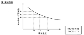
- FIG. 4 is a diagram illustrating a relationship between an environmental temperature and a motoring rotation speed according to the first embodiment.
- FIG. 4 is a diagram illustrating a relationship between a motoring rotation speed and IVC according to the first embodiment.
- (A)-(c) is a diagram showing valve timing at different motoring speeds.
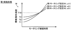
- FIG. 4 is a diagram illustrating a relationship (map) between a motoring duration and an environmental temperature according to the first embodiment.
- FIG. 5 is a diagram illustrating configurations of an engine, a variable valve mechanism, and an ECU according to a second embodiment.
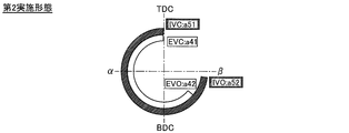
- FIG. 9 is a diagram illustrating valve timing during super-slow closing control according to a second embodiment. It is the flowchart which showed the control processing at the time of engine start by ECU of the engine by 2nd execution.
- the engine 1 of the first embodiment is incorporated in a hybrid vehicle 10.
- the engine 1 includes an engine body 2 (an example of an internal combustion engine body), a variable valve mechanism 3 (see FIG. 2), an intake pipe 4a connected upstream of the engine body 2 (see FIG. 2), and an engine body.
- An exhaust pipe 4b connected to the downstream side of the motor 2 an electric motor 5 used for motoring (an example of a hybrid drive motor), and an ECU (Engine Control Unit) 6 (an example of a control unit) are provided. .
- the engine body 2 includes a cylinder block 21 and a cylinder head 22 mounted on an upper part of the cylinder block 21.
- the cylinder block 21 has a cylinder 24 in which a combustion chamber 23 is provided inside.
- a crankshaft (not shown) is provided inside the engine body 2.
- the engine body 2 is provided with an intake valve 26a and an exhaust valve 26b.
- the engine 1 opens and closes the intake valve 26a and the exhaust valve 26b at a predetermined valve timing by rotating the camshafts 25a and 25b by the power of the crankshaft.
- the cylinder block 21 is provided with a water jacket 27 for flowing cooling water W for cooling the engine 1.
- the water jacket 27 is arranged adjacent to the combustion chamber 23.
- the variable valve mechanism 3 is configured so that the opening / closing timing of the intake valve 26a and the exhaust valve 26b of the combustion chamber 23 can be adjusted. More specifically, the variable valve mechanism 3 independently shifts the rotation of the camshafts 25a and 25b in the retard direction or the advance direction in order to shift the opening / closing timing of the intake valve 26a and the exhaust valve 26b. It is configured as follows.
- the variable valve mechanism 3 is installed in a timing chain (not shown), and continuously changes the opening / closing timing of the intake valve 26a (exhaust valve 26b) while maintaining the cam phase and the lift amount profile. It is configured as follows. Therefore, the angular width of the intake valve 26a (exhaust valve 26b) during the valve opening period does not change.
- the variable valve mechanism 3 is an electric mechanism that can be operated even before the engine is started.
- variable valve mechanism 3 advances or delays both the opening timing (hereinafter, IVO (Intake Valve Open)) and the closing timing (hereinafter, IVC (Intake Valve Valve Close)) of the intake valve 26a. It is configured.
- IVO Intake Valve Open
- IVC Intake Valve Valve Close
- variable valve mechanism 3 advances or delays both the opening timing (hereinafter, EVO (Exhaust Valve Open)) and the closing timing (hereinafter, EVC (Exhaust Valve Close)) of the exhaust valve 26b. It is configured. Note that the variable valve mechanism 3 is configured to be driven under the control of the ECU 6.
- the intake pipe 4a is configured to supply intake air to the combustion chamber 23 via the intake valve 26a.
- the exhaust pipe 4b is configured to discharge exhaust gas (exhaust gas) exhausted from the combustion chamber 23 through an exhaust valve 26b to the outside (atmosphere).
- the exhaust pipe 4b is provided with a catalyst C and a muffler F disposed downstream of the catalyst C.
- EGEGR pipe 4c for recirculating EGR gas is provided in intake pipe 4a and exhaust pipe 4b.
- the EGR pipe 4c is provided with an EGR valve (not shown) for opening and closing the EGR pipe 4c, and an EGR gas cooler (not shown) for cooling EGR gas.
- An injector (not shown) for injecting fuel into the intake passage is provided in the intake pipe 4a (upstream of the intake valve 26a).
- the electric motor 5 is configured to drive the engine body 2 at a predetermined rotation speed (set rotation speed) during motoring.
- the predetermined number of revolutions (set number of revolutions) is not a fixed number of revolutions but a number of revolutions that is set anew each time motoring is performed.
- the set predetermined number of revolutions (set number of revolutions) does not fluctuate during one motoring.
- the electric motor 5 is configured to be driven under the control of the ECU 6.
- the ECU 6 is configured to control each part of the engine 1.
- the ECU 6 is configured to control the electric motor 5 and the variable valve mechanism 3 so that the engine body 2 (in the cylinder 24 and in the combustion chamber 23) is effectively warmed up during motoring. I have. Thereby, the ECU 6 effectively raises the pressure in the cylinder 24 (inside the combustion chamber 23) and promotes atomization of fuel at the time of the first explosion (when fuel is supplied to the combustion chamber 23 and ignited for the first time). It is configured to reduce exhaust gas immediately after the first explosion.
- the ECU 6 is configured to perform control to set the rotation speed of the engine main body 2 to a predetermined rotation speed based on the environmental temperature at the start of the start of the engine main body 2. . Then, the ECU 6 drives the engine main body 2 by the electric motor 5 at a set predetermined number of revolutions (set number of revolutions) during a period from the time when fuel is supplied to the combustion chamber 23 of the engine main body 2 to the first ignition. It is configured to perform control.
- the ECU 6 is configured to set the predetermined rotation speed (set rotation speed) smaller as the environmental temperature increases, and to set the predetermined rotation speed (set rotation speed) higher as the environmental temperature decreases. ing.
- the environmental temperature is the temperature of the cooling water W flowing through the water jacket 27 of the engine body 2.
- the engine body 2 is provided with a temperature sensor S1 for measuring an environmental temperature (cooling water temperature of the cooling water W).
- the ECU 6 is configured to acquire information on the environmental temperature (cooling water temperature of the cooling water W) from the temperature sensor S1 before starting motoring.
- the ECU 6 sets the number of revolutions (set number of revolutions) of the engine body 2 at the time of performing motoring to R1 [rpm]. It is configured to be.
- the ECU 6 sets the number of revolutions (set number of revolutions) of the engine body 2 at the time of motoring to be greater than R1 [rpm]. It is configured to set a small R2 [rpm] (T1 ⁇ T2, R1> R2).
- the ECU 6 sets the rotation speed (set rotation speed) of the engine body 2 at the time of performing the motoring to be higher than R2 [rpm]. It is configured to set a small R3 [rpm] (T2 ⁇ T3, R2> R3). It should be noted that the lower the number of revolutions, the more the engine 1 can suppress the NV (Noise / Vibration, noise and vibration).
- the rotation speed of the engine body 2 during motoring is set within a range of about 1000 [rpm] or more and about 4000 [rpm] or less.
- the ECU 6 sets the timing at which the variable valve mechanism 3 closes the intake valve 26a to the retard side in accordance with setting the predetermined rotation speed (set rotation speed) to a large value. It is configured to perform.
- the timing control is control for setting the closing timing of the intake valve 26a so that the outside air can be introduced into the combustion chamber 23 most.
- the timing at which the intake valve 26a is closed is at least on the advance side of the intermediate phase ⁇ between the bottom dead center and the top dead center during the movement of the piston P from the bottom dead center to the top dead center. (See FIG. 5).
- the ECU 6 closes the intake valve 26a (IVC). ) Is set to a11 [degree].
- a setting for motoring in which the rotation speed is R1 and the IVC is a11 [degree] is referred to as a first motoring setting.
- the ECU 6 sets the rotational speed (set rotational speed) of the engine main body 2 to R2 [rpm], and sets the intake air to R2 [rpm].
- the timing (IVC) for closing the valve 26a is set to a21 [degree] on the more advanced side than a11 [degree].
- a setting for motoring in which the rotation speed is R2 [rpm] and the IVC is a21 [degree] is referred to as a second motoring setting.
- the ECU 6 sets the rotation speed (set rotation speed) of the engine main body 2 to R3 [rpm] and sets the intake air to R3 [rpm].
- the timing (IVC) for closing the valve 26a is set to a31 [degree] on the more advanced side than a21 [degree].
- a setting for motoring in which the rotation speed is R3 [rpm] and the IVC is a31 [degree] is referred to as a third motoring setting.
- EVC and EVO are set at the same angle regardless of the motoring setting.
- EVC is indicated by a41 [degree]
- EVO is indicated by a42 [degree].
- the IVO in the first motoring setting is indicated by a12 [degree].
- the IVO in the second motoring setting is indicated by a22 [degree].
- the IVO in the third motoring setting is indicated by a32 [degree].
- the ECU 6 determines, based on an estimation logic for estimating the temperature in the combustion chamber 23, the timing at which the in-cylinder temperature (estimated environmental temperature) exceeds a predetermined set temperature (ignition start temperature T10 [° C.]).
- the fuel is supplied to the fuel cell 23 to perform the first ignition. That is, the ECU 6 is configured to perform control for ending motoring based on the estimation logic.
- a predetermined set temperature ignition start temperature T10 [° C.]
- the set temperature is a temperature common to each of the first to third motoring settings.
- the estimation logic is, as shown in FIG. 6, a map M showing a relationship between the environmental temperature (in-cylinder temperature) and the driving duration (motoring duration) of the engine body 2 at a predetermined rotation speed.
- the ECU 6 continues the timing control until the first cycle when the fuel is supplied to the combustion chamber 23 and performs the first ignition, and in the second and subsequent cycles, the variable valve mechanism 3 controls the intake valve 26a during the steady operation. It is configured to return to the valve timing. In the second and subsequent cycles, the EGR gas (exhaust gas) is recirculated from the exhaust pipe 4b to the intake pipe 4a via the EGR pipe 4c.
- the ECU 6 acquires information on the environmental temperature (cooling water temperature of the cooling water W) from the temperature sensor S1 (see FIG. 2) provided in the engine main body 2 when starting the engine main body 2. Then, the ECU 6 sets the rotation speed of the engine body 2 to a predetermined rotation speed based on the acquired environmental temperature. Further, the ECU 6 performs control (timing control) for adjusting the timing at which the variable valve mechanism 3 closes the intake valve 26a according to a predetermined rotation speed (set rotation speed).
- the ECU 6 causes the electric motor 5 to drive the engine body 2 at a predetermined rotation speed (set rotation speed). Then, the ECU 6 determines the temperature (environment temperature (in-cylinder temperature)) in the combustion chamber 23 based on the estimation logic (map M) for estimating the temperature (environment temperature (in-cylinder temperature)) in the combustion chamber 23. At the timing exceeding the set temperature (ignition start temperature), fuel is supplied to the combustion chamber 23 to perform the first ignition.
- the ECU 6 continues the timing control until the first cycle when the fuel is supplied to the combustion chamber 23 and the first ignition is performed. Then, in the second and subsequent cycles, the ECU 6 causes the variable valve mechanism 3 to return to the valve timing of the intake valve 26a at the time of steady operation.
- the number of revolutions of the engine body 2 is set to a predetermined number of revolutions based on the environmental temperature at the start of the start of the engine body 2, and the fuel is stored in the combustion chamber 23 of the engine body 2.
- an ECU 6 for controlling the driving of the engine main body 2 at a set predetermined number of revolutions during a period from the start of ignition to the first ignition.
- variable valve mechanism 3 that can adjust the opening / closing timing of the intake valve 26a by the control of the ECU 6 is further provided, and the ECU 6 can introduce the most outside air based on the predetermined rotation speed. It is configured to perform timing control for setting the closing timing of the intake valve 26a.
- the external air can be effectively (most) introduced into the combustion chamber 23 in consideration of inertia supercharging, intake pulsation, and the like based on the rotation speed of the engine body 2.
- the pressure in the cylinder 24 can be effectively increased, and the combustion chamber 23 can be effectively warmed up. Therefore, more appropriate control for reducing the exhaust gas in accordance with the environmental temperature of the engine 1 can be performed. It can be carried out.
- the intake amount increases when the closing timing (IVC) of the intake valve 26a is retarded as the engine 1 rotates at a higher rotational speed.
- IVC closing timing
- the inertia supercharging effect becomes large, and at a high rotation speed, the inertia supercharging effect becomes small. Therefore, when the engine 1 is rotating at a high speed, the amount of intake air may be increased when the engine 1 is set to the advanced angle side.
- the ECU 6 continues the timing control until the first cycle when the fuel is supplied to the combustion chamber 23 and the first ignition is performed.
- the mechanism 3 is configured to perform control (ignition control) for returning to the valve timing of the intake valve 26a at the time of steady operation.
- the intake air amount is increased more than in the first cycle due to the influence of the recirculation of the EGR gas and the like, so it is necessary to set a predetermined valve timing. Therefore, with the above-described configuration, the timing control can be continued for a longer time than in the case where the timing control is finished only in the initial part of the period before the first ignition. It is possible to warm up more effectively. As a result, more appropriate control for reducing the exhaust gas according to the environmental temperature of the engine 1 can be performed.
- the ECU 6 determines whether the temperature in the combustion chamber 23 has exceeded a predetermined set temperature. It is configured to supply fuel and perform first ignition. Thus, by using the estimation logic, the ECU 6 does not need to perform an operation for determining the timing of performing the first ignition, and thus the control load on the ECU 6 can be reduced.
- the estimation logic includes the map M indicating the relationship between the temperature in the combustion chamber 23 and the driving duration of the engine body 2 at a predetermined rotation speed.
- the timing for performing the first ignition can be calculated in a complicated manner by the map M indicating the relationship between the temperature in the combustion chamber 23 and the driving duration (motoring duration) of the engine body 2 at a predetermined rotation speed. It can be easily determined without performing.
- the electric motor 5 for driving the piston P is further provided, and the ECU 6 sets the number of revolutions of the engine main body 2 to a predetermined value based on the environmental temperature at the start of the start of the engine main body 2.
- the electric motor 5 controls the engine main body 2 to be driven at the set predetermined number of revolutions. I have.
- the engine 201 (an example of an internal combustion engine) of the second embodiment shown in FIG. 7 includes the ECU 206 that performs super retard control that sets the timing of closing the intake valve 26a to a large retard side. Further, the engine 201 includes a temperature sensor S2 for measuring the temperature of the gas in the intake pipe 4a. The temperature sensor S2 is provided downstream of a throttle valve (not shown).
- the super retard control means that the engine 201 cannot be started, and the variable valve actuation is performed until the engine 201 reaches a phase where autonomous operation of the engine 201 is disabled even when fuel injection and ignition are performed.
- This is control by the ECU 206 for setting the relative rotation phase of the intake valve 26a to the retard side by the mechanism 3.
- the ECU 206 supplies the fuel to the combustion chamber 23 and, during a period from the time when the piston P moves from the bottom dead center to the top dead center during the period until the first ignition, is performed.
- the intake valve 26a is closed (IVC is set to a52 [degrees]) on the retard side of the phase ⁇ between the point and the top dead center. More specifically, the ECU 206 is configured to close the intake valve 26a at the top dead center (or near the top dead center) during a period from the time when fuel is supplied to the combustion chamber 23 and the first ignition is performed.
- the phase is more retarded than the phase of the intermediate ⁇ between the top dead center and the bottom dead center while the piston P moves from the top dead center to the bottom dead center.
- the engine 201 shown in FIG. 7 is configured to operate from the time when the piston P reaches the bottom dead center to the time when the piston P reaches the top dead center with the intake valve 26a opened.
- the gas in the cylinder 24 is blown back to the intake pipe 4a side.
- the temperature of the gas in the cylinder 24 rises due to frictional heat generated by the sliding between the inner peripheral surface of the cylinder 24 and the piston P, and the gas whose temperature has risen (increased in temperature) flows from the cylinder 24 into the intake pipe 4a. It is blown back to the side.
- an injector not shown
- the fuel can be effectively atomized.
- the ECU 206 is configured to supply fuel to the combustion chamber 23 by injecting fuel from the injector at a timing when the temperature of the temperature sensor S2 exceeds a predetermined set temperature, and to perform first ignition.
- step S1 the ECU 206 sets the rotation speed of the engine body 2 to a predetermined rotation speed based on the environmental temperature.
- This control is the same as in the first embodiment, and a description thereof will be omitted.
- step S2 the ECU 206 determines whether or not a cold start is to be performed based on the environmental temperature acquired via the temperature sensor S1. For example, it is determined whether or not the environmental temperature acquired via the temperature sensor S1 is equal to or higher than a predetermined threshold temperature, and whether or not it is a cold start. If it is a cold start, the process proceeds to step S3. If it is not a cold start, the process proceeds to step S7.
- step S3 the ECU 206 performs super retard control. That is, the ECU 206 sets the valve timing of closing the intake valve 26a at the top dead center (or near the top dead center) (the valve timing of the ultra-slow closing shown in FIG. 8).
- step S4 the ECU 206 determines whether or not the intake valve 26a has been changed to the ultra-slow closing valve timing as set in step S3 via the variable valve mechanism 12. If the valve timing has been changed to the ultra-slow closing valve timing, the process proceeds to step S5. On the other hand, if the valve timing has not been changed to the ultra-slow closing valve timing, step S4 is repeated. The determination by the ECU 206 in step S4 is performed using a predetermined rotation angle sensor (not shown) provided in the variable valve mechanism 12 or the like. The same applies to step S8 described later.
- step S5 the electric motor 5 (see FIG. 1) is driven by the ECU 206 to start motoring (drive of the piston P).
- the temperature of the gas in the cylinder 24 starts to increase due to frictional heat generated by sliding between the inner peripheral surface of the cylinder 24 and the piston P.
- step S6 the ECU 206 determines whether or not the gas temperature measured by the temperature sensor S2 (see FIG. 7) has exceeded a predetermined set temperature.
- the process proceeds to step S7.
- step S6 is repeated.
- step S7 the ECU 206 sets the intake valve 26a at a predetermined valve timing at which ignition is performed.
- step S8 the ECU 206 determines via the variable valve mechanism 12 whether or not the intake valve 26a has been changed to a predetermined valve timing for performing ignition as set in step S7. When it is changed to the predetermined valve timing for performing the ignition, the process proceeds to step S9. On the other hand, if the predetermined valve timing for performing ignition has not yet been changed, step S8 is repeated.
- step S9 the ignition of the engine 201 is disclosed by the ECU 206.
- variable valve mechanism 12 capable of adjusting the opening / closing timing of the intake valve 26a under the control of the ECU 206 is provided, and the period from when the fuel is supplied to the combustion chamber 23 until the first ignition is performed.
- the ECU 206 is configured to close the intake valve 26a on a more retarded side than the phase ⁇ between the bottom dead center and the top dead center during the movement of the piston P from the bottom dead center to the top dead center. I have. Accordingly, the gas in the cylinder 24, which has been heated due to friction between the piston P and the cylinder 24, is transferred to the intake pipe 4a for a relatively long time while the piston P moves from the bottom dead center to the top dead center. Can be blown back.
- the heated gas can be blown back to the intake pipe 4a for at least a time longer than half the time required for the piston P to move from the bottom dead center to the top dead center.
- atomization of fuel can be effectively promoted, so that unburned fuel can be reduced and exhaust gas can be reduced.
- the fuel injection amount at the time of the cold start can also be reduced. Since the amount of exhaust gas can be reduced, there is a possibility that the amount of noble metal used for the catalyst can be reduced.
- the ECU 206 is configured to close the intake valve 26a at or near the top dead center during a period from the time when fuel is supplied to the combustion chamber 23 and the first ignition is performed. ing. This allows the gas in the heated cylinder 24 to be blown back to the intake pipe 4a for a longer time while the piston P moves from the bottom dead center to the top dead center. As a result, atomization of the fuel can be more effectively promoted.
- the temperature sensor S2 for measuring the temperature in the intake pipe 4a is provided, and the ECU 206 sends the fuel to the combustion chamber 23 at a timing when the temperature of the temperature sensor S2 exceeds a predetermined set temperature. To perform the first ignition.
- the timing at which the fuel is supplied to the combustion chamber 23 by the temperature sensor S2 and the first ignition is performed can be accurately determined.
- the environmental temperature may be the outside air temperature around the engine body, the intake air temperature, or the temperature outside the vehicle (outside air temperature).
- valve timing of the intake valve was changed by the ECU to a timing different from that during the normal steady operation (timing control was performed) at the time of motoring.
- timing control was performed
- the valve timing of the intake valve may be set to the same timing as during normal steady operation (timing control may not be performed).
- the estimation logic is a map indicating the relationship between the temperature in the combustion chamber and the driving duration of the engine main body at a predetermined rotation speed, but the present invention is not limited to this. I can't.
- the estimation logic may be a predetermined calculation formula for deriving the temperature in the combustion chamber from the driving duration of the engine body at a predetermined rotation speed.
- the first ignition timing is determined by the ECU based on the estimation logic, but the present invention is not limited to this.
- the first ignition timing may be determined by the ECU based on a measurement result of a temperature sensor or the like capable of measuring the temperature in the combustion chamber without using the estimation logic.
- the rotation speed of the engine main body is set to be non-linear (quadratic curve) between the environmental temperature and the rotation speed of the engine main body.
- the present invention is not limited to this.
- the rotation speed of the engine body may be set by giving a linear (linear) relationship between the environmental temperature and the rotation speed of the engine body.
- the ECU performs predetermined control during motoring by the electric motor, but the present invention is not limited to this.
- the ECU when cranking is performed by the starter motor, the ECU may perform predetermined control.
- the set temperature is a temperature common to each of the first to third motoring settings, but the present invention is not limited to this. Absent.
- the set temperature (ignition start temperature) may be different from each other for each of the first to third motoring settings.
- the set temperature (ignition start temperature) may be a temperature obtained by adding T [° C.] (eg, 20 [° C.]) to the environmental temperature at the start of motoring in each of the first to third motoring settings. .
- the ECU is configured to set the closing timing of the intake valve to the retard side as the predetermined rotation speed (set rotation speed) is set large.
- the present invention is not limited to this.
- the ECU may be configured so that the closing timing of the intake valve is set to the advanced side as the predetermined rotation speed (set rotation speed) is increased.
- the timing for performing the first ignition is determined based on the temperature sensor provided in the intake pipe, but the present invention is not limited to this.
- the timing for performing the first ignition may be determined based on the estimation logic as in the first embodiment.
- the processing of the control unit has been described using the flow-driven flow in which the processing is sequentially performed along the processing flow, but the present invention is not limited to this.
- the processing of the control unit may be performed by an event-driven (event-driven) processing that executes processing in event units. In this case, it may be performed in a completely event-driven manner, or may be performed in a combination of event-driven and flow-driven.
Landscapes
- Engineering & Computer Science (AREA)
- Chemical & Material Sciences (AREA)
- Combustion & Propulsion (AREA)
- Mechanical Engineering (AREA)
- General Engineering & Computer Science (AREA)
- Theoretical Computer Science (AREA)
- Signal Processing (AREA)
- Output Control And Ontrol Of Special Type Engine (AREA)
- Combined Controls Of Internal Combustion Engines (AREA)
- Control Of Vehicle Engines Or Engines For Specific Uses (AREA)
Abstract
この内燃機関は、吸気弁および排気弁が設けられた内燃機関本体と、内燃機関本体の始動開始時の環境温度に基づいて、内燃機関本体の回転数を所定の回転数に設定して、内燃機関本体の燃焼室に燃料を供給して最初に点火するまでの期間において、設定した所定の回転数により内燃機関本体を駆動させる制御を行う制御部とを備える。
Description
本発明は、内燃機関に関し、特に、最初の点火を行うまでに燃焼室内を暖機する制御を行う制御部を備える内燃機関に関する。
従来、最初の点火を行うまでに燃焼室内を暖機する制御を行う制御部を備える内燃機関が知られている。このような内燃機関は、たとえば、特開2009-299538号公報に開示されている。
特開2009-299538号公報には、モータリングにより最初の点火を行うまでに燃焼室内を暖機する制御を行う制御装置と、可変バルブタイミング機構とを備えるエンジンが開示されている。制御装置は、モータリングの際に、可変バルブタイミング機構により、吸気弁を閉じるタイミングを、一律に、基準タイミング(定常運転時)よりも進角側に設定するように構成されている。これにより、エンジンは、吸気弁を下死点側で早閉じして多くの吸気をシリンダ内に留めることにより、吸気を圧縮してシリンダ内の温度を高めている。なお、シリンダ内の温度が高くなると、燃料の霧化が効果的に行われるため、初爆直後の排気ガスが低減される。
しかしながら、特開2009-299538号公報に記載のエンジンでは、モータリングの際に、吸気弁を閉じるタイミングを、一律に、基準タイミング(定常運転時)よりも進角側に設定しており、エンジンの環境温度に応じて排気ガスを低減するための適切な制御を行うことが困難であるという問題点がある。すなわち、上記特許文献1に記載のエンジンでは、可変バルブタイミング機構に対して、冷間始動などの環境温度を考慮した制御を行っていない。
この発明は、上記のような課題を解決するためになされたものであり、この発明の1つの目的は、内燃機関の環境温度に応じて排気ガスを低減するための適切な制御を行うことが可能な内燃機関を提供することである。
上記目的を達成するために、この発明の一の局面における内燃機関は、吸気弁および排気弁が設けられた内燃機関本体と、内燃機関本体の始動開始時の環境温度に基づいて、内燃機関本体の回転数を所定の回転数に設定して、内燃機関本体の燃焼室に燃料を供給して最初に点火するまでの期間において、設定した所定の回転数により内燃機関本体を駆動させる制御を行う制御部とを備える。
この発明の一の局面による内燃機関では、上記のように、内燃機関本体の始動開始時の環境温度に基づいて、内燃機関本体の回転数を所定の回転数に設定して、内燃機関本体の燃焼室に燃料を供給して最初に点火するまでの期間において、設定した所定の回転数により内燃機関本体を駆動させる制御を行う制御部を設ける。これにより、たとえば、環境温度が低い場合(冷間始動の場合)に、内燃機関本体の回転数を特に大きく設定すると、気筒とピストンとの間の摩擦および慣性過給により、燃焼室内を効果的に暖機することが可能になるので、内燃機関の環境温度に応じて排気ガスを低減するための適切な制御を行うことができる。なお、燃焼室内を暖機すると、燃料の霧化が促進され、最初に点火した際に発生する排気ガスを低減することができる。
上記一の局面による内燃機関において、好ましくは、制御部による制御により、吸気弁の開閉タイミングを調整可能な可変動弁機構をさらに備え、制御部は、所定の回転数に基づく最も外気を導入可能な吸気弁の閉タイミングに設定するタイミング制御を行うように構成されている。
このように構成すれば、内燃機関本体の回転数に基づく慣性過給や吸気脈動などを考慮して、効果的に(最も)外気を燃焼室に導入することができる。その結果、燃焼室内の圧力を効果的に高めて燃焼室内を効果的に暖機することができるので、内燃機関の環境温度に応じて排気ガスを低減するためのより適切な制御を行うことができる。
上記タイミング制御を行う構成において、好ましくは、制御部は、燃焼室に燃料を供給して最初の点火を行う際の1サイクル目までタイミング制御を継続するとともに、2サイクル目以降では、可変動弁機構により定常運転時の吸気弁のバルブタイミングに復帰させるように構成されている。
ここで、2サイクル目以降では、EGRガスの再循環などの影響により1サイクル目よりも吸気量が増加するため、所定のバルブタイミングに設定する必要がある。そこで、上記のように構成すれば、最初の点火前の期間のうちの初期のみでタイミング制御を終える場合と比較して、タイミング制御をより長く継続することができるので、燃焼室内をより効果的に暖機することができる。その結果、内燃機関の環境温度に応じて排気ガスを低減するためのより適切な制御を行うことができる。
上記一の局面による内燃機関において、好ましくは、制御部による制御により、吸気弁の開閉タイミングを調整可能な可変動弁機構をさらに備え、燃焼室に燃料を供給して最初に点火するまでの期間において、制御部は、ピストンが下死点から上死点に移動する間における下死点と上死点との中間の位相よりも遅角側で、吸気弁を閉じるように構成されている。
このように構成すれば、ピストンと気筒との摩擦などにより高温化した気筒内のガスを、ピストンが下死点から上死点に向けて移動する間において、比較的長い時間にわたり吸気管側に吹き戻すことができる。すなわち、少なくとも、ピストンが下死点から上死点に向けて移動するのに要する時間の半分よりも長い時間にわたり吸気管側に高温化したガスを吹き戻すことができる。その結果、燃料の霧化を効果的に促進することができるので、未燃燃料を低減し、排気ガスを低減することができる。これによって、冷間始動時の燃料の噴射量も低減することができる。なお、排気ガスを低減することができることから、触媒に用いられる貴金属の量を減らせる可能性がある。
この場合、好ましくは、燃焼室に燃料を供給して最初に点火するまでの期間において、制御部は、上死点または上死点近傍で吸気弁を閉じるように構成されている。
このように構成すれば、高温化した気筒内のガスを、ピストンが下死点から上死点に向けて移動する間において、より長い時間にわたり吸気管側に吹き戻すことができる。その結果、燃料の霧化をより効果的に促進することができる。
上記一の局面による内燃機関において、好ましくは、制御部は、燃焼室内の温度を推定する推定ロジックに基づいて、燃焼室内の温度が所定の設定温度を超えたタイミングで、燃焼室に燃料を供給して最初の点火を行うように構成されている。
このように構成すれば、推定ロジックを用いることにより、制御部において、最初の点火を行うタイミングを判断する演算などが不要となるので、制御部の制御負荷を軽減することができる。
この場合、好ましくは、推定ロジックは、燃焼室内の温度と、所定の回転数による内燃機関本体の駆動継続時間との関係を示すマップを含む。
このように構成すれば、燃焼室内の温度と、所定の回転数による内燃機関本体の駆動継続時間(モータリング継続時間)との関係を示すマップにより、最初の点火を行うタイミングを、複雑な演算を行うことなく容易に決定することができる。
上記一の局面による内燃機関において、好ましくは、吸気管内の温度を測定する温度センサをさらに備え、制御部は、温度センサの温度が所定の設定温度を超えたタイミングで、燃焼室に燃料を供給して最初の点火を行うように構成されている。
このように構成すれば、温度センサにより燃焼室に燃料を供給して最初の点火を行うタイミングを精度よく判断することができる。
上記一の局面による内燃機関において、好ましくは、環境温度とは、内燃機関本体の周囲の外気温度、および、内燃機関本体の冷却水温度の少なくとも一方を含む。
このように構成すれば、内燃機関が一般的に備える内燃機関本体の周囲の外気温度を測定する温度センサ、または、内燃機関本体の冷却水温度を測定する温度センサを用いて、最初の点火を行うまでに燃焼室内を暖機する制御を行うことができる。
上記一の局面による内燃機関において、好ましくは、ピストンを駆動させるハイブリッド駆動用モータをさらに備え、制御部は、内燃機関本体の始動開始時の環境温度に基づいて、内燃機関本体の回転数を所定の回転数に設定して、燃焼室に燃料を供給して最初に点火するまでの期間において、ハイブリッド駆動用モータによって、設定した所定の回転数により内燃機関本体を駆動させる制御を行うように構成されている。
このように構成すれば、ハイブリッド駆動用モータを用いて、モータリングを行うことによって、内燃機関の環境温度に応じて排気ガスを低減するための適切な制御を行うことができる。
以下、本発明を具体化した実施形態を図面に基づいて説明する。
[第1実施形態]
図1~図6を参照して、第1実施形態によるエンジン1(内燃機関の一例)の構成について説明する。
図1~図6を参照して、第1実施形態によるエンジン1(内燃機関の一例)の構成について説明する。
図1に示すように、第1実施形態のエンジン1は、ハイブリット車10に組み込まれている。
エンジン1は、エンジン本体2(内燃機関本体の一例)と、可変動弁機構3(図2参照)と、エンジン本体2の上流側に接続される吸気管4a(図2参照)と、エンジン本体2の下流側に接続される排気管4bと、モータリングに使用される電気モータ5(ハイブリッド駆動用モータの一例)と、ECU(Engine Control Unit)6(制御部の一例)とを備えている。
図2に示すように、エンジン本体2は、シリンダブロック21と、シリンダブロック21の上部に取り付けられるシリンダヘッド22とを含んでいる。シリンダブロック21は、燃焼室23が内側に設けられた気筒24を有している。エンジン本体2内には、クランクシャフト(図示せず)が設けられている。また、エンジン本体2には、吸気弁26aおよび排気弁26bが設けられている。エンジン1は、クランクシャフトの動力によりカムシャフト25aおよび25bを回転させることによって、吸気弁26aおよび排気弁26bをそれぞれ所定のバルブタイミングにより開閉する。
シリンダブロック21には、エンジン1を冷却する冷却水Wを流通させるためのウォータージャケット27が設けられている。ウォータージャケット27は、燃焼室23に隣接して配置されている。モータリングの際に、エンジン1(燃焼室23、気筒24)は、ピストンPと気筒24との間における摩擦や、気筒24内(燃焼室23内)での空気の圧縮により、温度上昇する。このため、モータリングの際に、冷却水Wも、温度上昇したエンジン1から熱を奪うことにより、温度上昇する。
可変動弁機構3は、燃焼室23の吸気弁26aおよび排気弁26bの開閉タイミングを調整可能に構成されている。詳細には、また、可変動弁機構3は、吸気弁26aおよび排気弁26bの開閉のタイミングをずらすために、カムシャフト25aおよび25bの回転をそれぞれ独立して遅角方向または進角方向にずらすように構成されている。可変動弁機構3は、タイミングチェーン(図示せず)に設置されており、吸気弁26a(排気弁26b)の開閉タイミングを、カムの位相およびリフト量のプロフィールを維持しながら連続的に変更するように構成されている。したがって、吸気弁26a(排気弁26b)の開弁期間の角度幅は変わることがない。また、可変動弁機構3は、エンジン始動前でも稼働可能な電動式の機構である。
すなわち、可変動弁機構3は、吸気弁26aの開くタイミング(以下、IVO(Intake Valve Open))および閉じるタイミング(以下、IVC(Intake Valve Close))を、共に早めるか、または、共に遅らせるように構成されている。
また、可変動弁機構3は、排気弁26bの開くタイミング(以下、EVO(Exhaust Valve Open))および閉じるタイミング(以下、EVC(Exhaust Valve Close))を、共に早めるか、または、共に遅らせるように構成されている。なお、可変動弁機構3は、ECU6による制御の下、駆動されるように構成されている。
吸気管4aは、吸気弁26aを介して燃焼室23に吸気を供給するように構成されている。排気管4bは、排気弁26bを介して燃焼室23から排出された排気(排気ガス)を外部(大気)に放出するように構成されている。排気管4bには、触媒Cと、触媒Cの下流側に配置されるマフラーFとが設けられている。
吸気管4aおよび排気管4bには、EGRガス(排気ガス)を再循環するためのEGR管4cが設けられている。EGR管4cには、EGR管4cを開閉するEGRバルブ(図示せず)と、EGRガスを冷却するEGRガスクーラ―(図示せず)とが設けられている。なお、吸気管4a(吸気弁26aの上流側)には、吸気通路に燃料を噴射するインジェクタ(図示せず)が設けられている。
電気モータ5は、モータリングの際に、エンジン本体2を所定の回転数(設定回転数)で駆動させるように構成されている。所定の回転数(設定回転数)とは、一定の回転数ではなく、モータリングを行うごとに改めて設定される回転数である。設定された所定の回転数(設定回転数)は、1回のモータリングの途中で変動することはない。なお、電気モータ5は、ECU6による制御の下、駆動されるように構成されている。
〈ECUの構成〉
ECU6は、エンジン1の各部を制御するように構成されている。ECU6は、モータリングの際に、エンジン本体2(気筒24内、燃焼室23内)が効果的に暖機されるように、電気モータ5および可変動弁機構3を制御するように構成されている。これにより、ECU6は、気筒24内(燃焼室23内)を効果的に昇圧して、初爆時(燃焼室23に燃料を供給して最初に点火する際)の燃料の霧化を促進し、初爆直後の排気ガスを低減するように構成されている。
ECU6は、エンジン1の各部を制御するように構成されている。ECU6は、モータリングの際に、エンジン本体2(気筒24内、燃焼室23内)が効果的に暖機されるように、電気モータ5および可変動弁機構3を制御するように構成されている。これにより、ECU6は、気筒24内(燃焼室23内)を効果的に昇圧して、初爆時(燃焼室23に燃料を供給して最初に点火する際)の燃料の霧化を促進し、初爆直後の排気ガスを低減するように構成されている。
詳細には、第1実施形態では、ECU6は、エンジン本体2の始動開始時の環境温度に基づいて、エンジン本体2の回転数を所定の回転数に設定する制御を行うように構成されている。そして、ECU6は、エンジン本体2の燃焼室23に燃料を供給して最初に点火するまでの期間において、電気モータ5によって、設定した所定の回転数(設定回転数)によりエンジン本体2を駆動させる制御を行うように構成されている。
なお、ECU6は、環境温度が高くなる程、所定の回転数(設定回転数)を小さく設定し、環境温度が低くなる程、所定の回転数(設定回転数)を大きく設定するように構成されている。
ここで、環境温度とは、エンジン本体2のウォータージャケット27内を流れる冷却水Wの冷却水温度である。エンジン本体2には、環境温度(冷却水Wの冷却水温度)を測定するための温度センサS1が設けられている。ECU6は、モータリングを開始する前に、温度センサS1から環境温度(冷却水Wの冷却水温度)の情報を取得するように構成されている。
たとえば、図3に示すように、ECU6は、環境温度がT1[℃]である場合には、モータリングを行う際のエンジン本体2の回転数(設定回転数)を、R1[rpm]に設定するように構成されている。
また、ECU6は、環境温度がT1[℃]よりも高いT2[℃]である場合には、モータリングを行う際のエンジン本体2の回転数(設定回転数)を、R1[rpm]よりも小さいR2[rpm]に設定するように構成されている(T1<T2、R1>R2)。
また、ECU6は、環境温度がT2[℃]よりも高いT3[℃]である場合には、モータリングを行う際のエンジン本体2の回転数(設定回転数)を、R2[rpm]よりも小さいR3[rpm]に設定するように構成されている(T2<T3、R2>R3)。なお、回転数が低い程、エンジン1は、NV(Noise Vibration、騒音振動)を小さく抑えることが可能である。
なお、一例ではあるが、モータリングの際のエンジン本体2の回転数は、約1000[rpm]以上約4000[rpm]以下の範囲内で設定される。
また、図4に示すように、ECU6は、所定の回転数(設定回転数)を大きく設定するのに伴い、可変動弁機構3により吸気弁26aを閉じるタイミングを遅角側に設定するタイミング制御を行うように構成されている。タイミング制御は、最も外気を燃焼室23に導入可能なように吸気弁26aの閉タイミングを設定する制御である。なお、タイミング制御において、吸気弁26aを閉じるタイミングは、少なくとも、ピストンPが下死点から上死点に移動する間における下死点と上死点との中間の位相αよりも進角側となるように設定される(図5参照)。
たとえば、ECU6は、環境温度がT1[℃]であることに基づいて、エンジン本体2の回転数(設定回転数)をR1[rpm]に設定した場合には、吸気弁26aを閉じるタイミング(IVC)をa11[度]に設定するように構成されている。以下では、回転数がR1、IVCがa11[度]となるモータリングのための設定を、第1モータリング設定とする。
また、ECU6は、環境温度がT1[℃]よりも高いT2[℃]であることに基づいて、エンジン本体2の回転数(設定回転数)をR2[rpm]に設定した場合には、吸気弁26aを閉じるタイミング(IVC)をa11[度]よりも進角側のa21[度]に設定するように構成されている。以下では、回転数がR2[rpm]、IVCがa21[度]となるモータリングのための設定を、第2モータリング設定とする。
また、ECU6は、環境温度がT2[℃]よりも高いT3[℃]であることに基づいて、エンジン本体2の回転数(設定回転数)をR3[rpm]に設定した場合には、吸気弁26aを閉じるタイミング(IVC)をa21[度]よりも進角側のa31[度]に設定するように構成されている。以下では、回転数がR3[rpm]、IVCがa31[度]となるモータリングのための設定を、第3モータリング設定とする。
なお、図5に示すように、いずれのモータリング設定の場合でも、EVCおよびEVOは同一角度に設定されている。図5では、EVCをa41[度]、EVOをa42[度]で示している。また、第1モータリング設定でのIVOをa12[度]で示している。また、第2モータリング設定でのIVOをa22[度]で示している。また、第3モータリング設定でのIVOをa32[度]で示している。
ECU6は、燃焼室23内の温度を推定する推定ロジックに基づいて、筒内温度(推定された環境温度)が所定の設定温度(点火開始温度T10[℃])を超えたタイミングで、燃焼室23に燃料を供給して最初の点火を行うように構成されている。すなわち、ECU6は、推定ロジックに基づいて、モータリングを終えるための制御を行うように構成されている。なお、推定ロジックにより推定される筒内の所定の設定温度(点火開始温度T10[℃])は、燃料の霧化が適切に行われ、初爆後において、排気ガスを低減することが可能であると推定される所定の温度である。なお、設定温度(点火開始温度T10[℃])は、第1~第3モータリング設定の各設定に対して共通の温度である。
推定ロジックは、図6に示すように、環境温度(筒内温度)と、所定の回転数によるエンジン本体2本体の駆動継続時間(モータリング継続時間)との関係を示すマップMである。
なお、図6では、各モータリング設定において、点火開始温度T10[℃]に達するモータリング継続時間が互いに略同じとなるように図示しているが、点火開始温度T10[℃]に達するモータリング継続時間が互いに異なっていてもよい。
ECU6は、燃焼室23に燃料を供給して最初の点火を行う際の1サイクル目までタイミング制御を継続するとともに、2サイクル目以降では、可変動弁機構3により定常運転時の吸気弁26aのバルブタイミングに復帰させるように構成されている。なお、2サイクル目以降では、EGRガス(排気ガス)が、EGR管4cを介して排気管4bから吸気管4aに再循環される。
(ECUによるモータリングの際の制御の流れ)
次に、図2~図6を参照して、ECU6によるモータリングの際の制御の流れについて説明する。
次に、図2~図6を参照して、ECU6によるモータリングの際の制御の流れについて説明する。
まず、ECU6は、エンジン本体2の始動開始時に、エンジン本体2に設けられた温度センサS1(図2参照)から、環境温度(冷却水Wの冷却水温度)の情報を取得する。そして、ECU6は、取得した環境温度に基づいて、エンジン本体2の回転数を所定の回転数に設定する。また、ECU6は、所定の回転数(設定回転数)に応じて、可変動弁機構3により吸気弁26aを閉じるタイミングを調整する制御(タイミング制御)を行う。
次に、ECU6は、電気モータ5により、エンジン本体2を所定の回転数(設定回転数)で駆動させる。そして、ECU6は、燃焼室23内の温度(環境温度(筒内温度))を推定する推定ロジック(マップM)に基づいて、燃焼室23内の温度(環境温度(筒内温度))が所定の設定温度(点火開始温度)を超えたタイミングで、燃焼室23に燃料を供給して最初の点火を行う。
なお、ECU6は、燃焼室23に燃料を供給して最初の点火を行う際の1サイクル目までタイミング制御を継続する。そして、ECU6は、2サイクル目以降では、可変動弁機構3により定常運転時の吸気弁26aのバルブタイミングに復帰させる。
(第1実施形態の効果)
第1実施形態では、以下のような効果を得ることができる。
第1実施形態では、以下のような効果を得ることができる。
第1実施形態では、上記のように、エンジン本体2の始動開始時の環境温度に基づいて、エンジン本体2の回転数を所定の回転数に設定して、エンジン本体2の燃焼室23に燃料を供給して最初に点火するまでの期間において、設定した所定の回転数によりエンジン本体2を駆動させる制御を行うECU6を設ける。これによって、たとえば、環境温度が低い場合(冷間始動の場合)に、エンジン本体2の回転数を特に大きく設定すると、気筒24とピストンPとの間の摩擦および慣性過給により、燃焼室23内を効果的に暖機することが可能になるので、エンジン1の環境温度に応じて排気ガスを低減するための適切な制御を行うことができる。なお、燃焼室23内を暖機すると、燃料の霧化が促進され、最初に点火した際に発生する排気ガスを低減することができる。
第1実施形態では、上記のように、ECU6による制御により、吸気弁26aの開閉タイミングを調整可能な可変動弁機構3をさらに備え、ECU6は、所定の回転数に基づく最も外気を導入可能な吸気弁26aの閉タイミングに設定するタイミング制御を行うように構成されている。これによって、エンジン本体2の回転数に基づく慣性過給や吸気脈動などを考慮して、効果的に(最も)外気を燃焼室23に導入することができる。その結果、気筒24内の圧力を効果的に高めて燃焼室23内を効果的に暖機することができるので、エンジン1の環境温度に応じて排気ガスを低減するためのより適切な制御を行うことができる。なお、慣性過給の観点から、エンジン1が高回転数である程、吸気弁26aの閉タイミング(IVC)を遅角側にすると吸気量が大きくなるが、吸気脈動(空気抵抗)を考慮すると、エンジン1が中回転数(約3000rpmから約4000rpm)で慣性過給効果が大きくなり、高回転数では慣性過給効果が小さくなる。したがって、エンジン1の高速回転時には進角側にした方が、吸気量が大きくなる場合がある。
第1実施形態では、上記のように、ECU6は、燃焼室23に燃料を供給して最初の点火を行う際の1サイクル目までタイミング制御を継続するとともに、2サイクル目以降では、可変動弁機構3により定常運転時の吸気弁26aのバルブタイミングに復帰させる制御(点火制御)を行うように構成されている。ここで、2サイクル目以降では、EGRガスの再循環などの影響により1サイクル目よりも吸気量が増加するため、所定のバルブタイミングに設定する必要がある。そこで、上記のように構成することにより、最初の点火前の期間のうちの初期のみでタイミング制御を終える場合と比較して、タイミング制御をより長く継続することができるので、燃焼室23内をより効果的に暖機することができる。その結果、エンジン1の環境温度に応じて排気ガスを低減するためのより適切な制御を行うことができる。
第1実施形態では、上記のように、ECU6は、燃焼室23内の温度を推定する推定ロジックに基づいて、燃焼室23内の温度が所定の設定温度を超えたタイミングで、燃焼室23に燃料を供給して最初の点火を行うように構成されている。これによって、推定ロジックを用いることによって、ECU6において、最初の点火を行うタイミングを判断する演算などが不要となるので、ECU6の制御負荷を軽減することができる。
第1実施形態では、上記のように、推定ロジックは、燃焼室23内の温度と、所定の回転数によるエンジン本体2の駆動継続時間との関係を示すマップMを含む。これによって、燃焼室23内の温度と、所定の回転数によるエンジン本体2の駆動継続時間(モータリング継続時間)との関係を示すマップMにより、最初の点火を行うタイミングを、複雑な演算を行うことなく容易に決定することができる。
第1実施形態では、上記のように、ピストンPを駆動させる電気モータ5をさらに備え、ECU6は、エンジン本体2の始動開始時の環境温度に基づいて、エンジン本体2の回転数を所定の回転数に設定して、燃焼室23に燃料を供給して最初に点火するまでの期間において、電気モータ5によって、設定した所定の回転数によりエンジン本体2を駆動させる制御を行うように構成されている。これによって、電気モータ5を用いて、モータリングを行うことによって、エンジン1の環境温度に応じて排気ガスを低減するための適切な制御を行うことができる。
[第2実施形態]
次に、図1および図7~図9を参照して、本発明の第2実施形態について説明する。この第2実施形態では、ECU6によりタイミング制御を行う第1実施形態の構成とは異なり、タイミング制御を行うことなく、ECU206(制御部の一例)により吸気弁26aを閉じるタイミングを、上記第1実施形態のタイミング(図5参照)よりもさらに遅くする例(超遅角制御を行う例)について説明する。なお、上記第1実施形態と同様の構成は、第1実施形態と同じ符号を付して図示するとともに説明を省略する。
次に、図1および図7~図9を参照して、本発明の第2実施形態について説明する。この第2実施形態では、ECU6によりタイミング制御を行う第1実施形態の構成とは異なり、タイミング制御を行うことなく、ECU206(制御部の一例)により吸気弁26aを閉じるタイミングを、上記第1実施形態のタイミング(図5参照)よりもさらに遅くする例(超遅角制御を行う例)について説明する。なお、上記第1実施形態と同様の構成は、第1実施形態と同じ符号を付して図示するとともに説明を省略する。
図7に示す第2実施形態のエンジン201(内燃機関の一例)は、吸気弁26aを閉じるタイミングを大きく遅角側に設定する超遅角制御を行うECU206を備えている。また、エンジン201は、吸気管4a内のガスの温度を測定する温度センサS2を備えている。なお、温度センサS2は、スロットルバルブ(図示せず)の下流側に設けられている。
ここで、超遅角制御とは、エンジン201が始動不能となり、かつ、エンジン201に燃料噴射および点火を行ってもエンジン201の自律的な稼働が不能となるような位相に達するまで可変動弁機構3により吸気弁26aの相対回転位相を遅角側に設定するECU206の制御である。
具体的には、図8に示すように、ECU206は、燃焼室23に燃料を供給して最初に点火するまでの期間において、ピストンPが下死点から上死点に移動する間における下死点と上死点との中間の位相αよりも遅角側で、吸気弁26aを閉じる(IVCをa52[度]に設定する)ように構成されている。より具体的には、ECU206は、燃焼室23に燃料を供給して最初に点火するまでの期間において、上死点(または上死点近傍)で吸気弁26aを閉じるように構成されている。
一例ではあるが、IVCがa52[度]に設定された場合、ピストンPが上死点から下死点に移動する間における上死点と下死点との中間βの位相よりも遅角側のa51[度]にIVOが設定される。
なお、超遅角制御が行われた場合、図7に示すエンジン201は、吸気弁26aが開いた状態でピストンPが下死点に到達してからピストンPが上死点に到達するまでの略すべでの位相(時間)において、気筒24内のガスを吸気管4a側に吹き戻すように構成されている。この際、気筒24の内周面とピストンPとの摺動により発生した摩擦熱によって気筒24内のガスの温度が上昇し、温度上昇(高温化)したガスが、気筒24内から吸気管4a側に吹き戻される。その結果、吸気通路に燃料を噴射するインジェクタ(図示せず)から燃料が噴射された際に、効果的に燃料を霧化させることができる。
ECU206は、温度センサS2の温度が所定の設定温度を超えたタイミングで、インジェクタから燃料を噴射することにより、燃焼室23に燃料を供給して、最初の点火を行うように構成されている。
(エンジン始動時のECUの制御処理)
次に、図9を参照して、エンジン始動時のECU206の制御処理について説明する。
次に、図9を参照して、エンジン始動時のECU206の制御処理について説明する。
まず、ステップS1において、ECU206により、環境温度に基づいてエンジン本体2の回転数が所定の回転数に設定される。この制御については、上記第1実施形態と同様であるため、説明を省略する。
次に、ステップS2において、ECU206により、温度センサS1を介して取得した環境温度に基づいて冷間始動であるか否かを判断する。たとえば、温度センサS1を介して取得した環境温度が所定のしきい値温度以上であるか未満であるかを判断して、冷間始動であるか否かを判断する。そして、冷間始動である場合、ステップS3に進む。また、冷間始動でない場合、ステップS7に進む。
次に、ステップS3において、ECU206により、超遅角制御が行われる。すなわち、ECU206により、上死点(または上死点近傍)で吸気弁26aを閉じるバルブタイミング(図8に示す超遅閉じのバルブタイミング)に設定される。
次に、ステップS4において、ECU206により、可変動弁機構12を介して吸気弁26aがステップS3で設定された通りの超遅閉じのバルブタイミングに変更されたか否かが判断される。超遅閉じのバルブタイミングに変更された場合、ステップS5に進む。一方、未だ超遅閉じのバルブタイミングに変更されていない場合、ステップS4が繰り返される。なお、ステップS4のECU206による判断は、可変動弁機構12に設けられた所定の回転角度センサ(図示せず)などを用いて行われる。後述するステップS8も同様である。
次に、ステップS5において、ECU206により、電気モータ5(図1参照)が駆動されてモータリング(ピストンPの駆動)が開始される。その結果、気筒24の内周面とピストンPとの摺動により発生した摩擦熱によって、気筒24内のガスの温度が上昇し始める。
次に、ステップS6において、ECU206により、温度センサS2(図7参照)により測定されるガスの温度が所定の設定温度を超えたか否かが判断される。温度センサS2の測定温度が所定の設定温度を超えている場合、ステップS7に進む。一方、未だ温度センサS2の測定温度が所定の設定温度を超えていない場合、ステップS6が繰り返される。
次に、ステップS7において、ECU206により、点火を行う所定のバルブタイミングに吸気弁26aが設定される。
次に、ステップS8において、ECU206により、可変動弁機構12を介して吸気弁26aがステップS7で設定された通りの点火を行う所定のバルブタイミングに変更されたか否かが判断される。点火を行う所定のバルブタイミングに変更された場合、ステップS9に進む。一方、未だ点火を行う所定のバルブタイミングに変更されていない場合、ステップS8が繰り返される。
次に、ステップS9において、ECU206により、エンジン201の点火が開示される。
(第2実施形態の効果)
第2実施形態では、以下のような効果を得ることができる。
第2実施形態では、以下のような効果を得ることができる。
第2実施形態では、上記のように、ECU206による制御により、吸気弁26aの開閉タイミングを調整可能な可変動弁機構12を備え、燃焼室23に燃料を供給して最初に点火するまでの期間において、ECU206は、ピストンPが下死点から上死点に移動する間における下死点と上死点との中間の位相αよりも遅角側で、吸気弁26aを閉じるように構成されている。これによって、ピストンPと気筒24との摩擦などにより高温化した気筒24内のガスを、ピストンPが下死点から上死点に向けて移動する間において、比較的長い時間にわたり吸気管4a側に吹き戻すことができる。すなわち、少なくとも、ピストンPが下死点から上死点に向けて移動するのに要する時間の半分よりも長い時間にわたり吸気管4a側に高温化したガスを吹き戻すことができる。その結果、燃料の霧化を効果的に促進することができるので、未燃燃料を低減し、排気ガスを低減することができる。これによって、冷間始動時の燃料の噴射量も低減することができる。なお、排気ガスを低減することができることから、触媒に用いられる貴金属の量を減らせる可能性がある。
第2実施形態では、上記のように、燃焼室23に燃料を供給して最初に点火するまでの期間において、ECU206は、上死点または上死点近傍で吸気弁26aを閉じるように構成されている。これによって、高温化した気筒24内のガスを、ピストンPが下死点から上死点に向けて移動する間において、より長い時間にわたり吸気管4a側に吹き戻すことができる。その結果、燃料の霧化をより効果的に促進することができる。
第2実施形態では、上記のように、吸気管4a内の温度を測定する温度センサS2を備え、ECU206は、温度センサS2の温度が所定の設定温度を超えたタイミングで、燃焼室23に燃料を供給して最初の点火を行うように構成されている。これによって、温度センサS2により燃焼室23に燃料を供給して最初の点火を行うタイミングを精度よく判断することができる。
[変形例]
今回開示された実施形態は、全ての点で例示であり制限的なものではないと考えられるべきである。本発明の範囲は、上記実施形態の説明ではなく特許請求の範囲によって示され、さらに特許請求の範囲と均等の意味および範囲内での全ての変更(変形例)が含まれる。
今回開示された実施形態は、全ての点で例示であり制限的なものではないと考えられるべきである。本発明の範囲は、上記実施形態の説明ではなく特許請求の範囲によって示され、さらに特許請求の範囲と均等の意味および範囲内での全ての変更(変形例)が含まれる。
たとえば、上記第1および第2実施形態では、環境温度をエンジンの冷却水の温度とした例を示したが、本発明はこれに限られない。本発明では、環境温度をエンジン本体の周囲の外気温度、吸気温度または車両の外の温度(外気温度)などとしてもよい。
また、上記第1実施形態では、モータリングの際に、ECUにより吸気弁のバルブタイミングを通常の定常運転時とは異なるタイミングに変更した(タイミング制御を行った)例を示したが、本発明はこれに限られない。本発明では、たとえば、モータリングの際に、吸気弁のバルブタイミングを通常の定常運転時と同じタイミングに設定してもよい(タイミング制御を行わなくてもよい)。
また、上記第1実施形態では、推定ロジックを、燃焼室内の温度と、所定の回転数によるエンジン本体の駆動継続時間との関係を示すマップとした例を示したが、本発明はこれに限られない。本発明では、たとえば、推定ロジックを、所定の回転数によるエンジン本体の駆動継続時間から、燃焼室内の温度を導出する所定の計算式としてもよい。
また、上記第1実施形態では、推定ロジックに基づいて、最初の点火のタイミングをECUにより判断した例を示したが、本発明はこれに限られない。本発明では、たとえば、推定ロジックに基づくことなく、燃焼室内の温度を測定可能な温度センサなどの測定結果に基づいて、最初の点火のタイミングをECUにより判断してもよい。
また、上記第1および第2実施形態では、図3に示すように、環境温度とエンジン本体の回転数とに非線形的(2次曲線的)な関係を持たせて、エンジン本体の回転数を設定した例を示したが、本発明はこれに限られない。本発明では、たとえば、環境温度とエンジン本体の回転数とに線形的(直線的)な関係を持たせて、エンジン本体の回転数を設定してもよい。
また、上記第1実施形態では、電気モータによるモータリングの際に、ECUによる所定の制御を行った例を示したが、本発明はこれに限られない。本発明では、セルモータによるクランキングの際に、ECUによる所定の制御を行ってもよい。
また、上記第1実施形態では、設定温度(点火開始温度)を、第1~第3モータリング設定の各設定に対して共通の温度とした例を示したが、本発明はこれに限られない。本発明では、設定温度(点火開始温度)を、第1~第3モータリング設定の各設定に対して、互いに異なる温度としてもよい。たとえば、設定温度(点火開始温度)を、第1~第3モータリング設定の各設定におけるモータリング開始時の環境温度に、T[℃](たとえば20[℃])を加えた温度としてもよい。
また、上記第1実施形態では、所定の回転数(設定回転数)を大きく設定するのに伴い、吸気弁の閉タイミングを遅角側に設定するように、ECUを構成した例を示したが、本発明はこれに限られない。本発明では、所定の回転数(設定回転数)を大きく設定するのに伴い、吸気弁の閉タイミングを進角側に設定するように、ECUを構成してもよい。
また、上記第2実施形態では、吸気管に設けられた温度センサに基づいて最初の点火を行うタイミングを判断するように構成した例を示したが、本発明はこれに限られない。本発明では、上記第1実施形態のように、推定ロジックに基づいて最初の点火を行うタイミングを判断してもよい。
また、上記第2実施形態では、説明の便宜上、制御部の処理を処理フローに沿って順番に処理を行うフロー駆動型のフローを用いて説明したが、本発明はこれに限られない。本発明では、制御部の処理を、イベント単位で処理を実行するイベント駆動型(イベントドリブン型)の処理により行ってもよい。この場合、完全なイベント駆動型で行ってもよいし、イベント駆動およびフロー駆動を組み合わせて行ってもよい。
1、201 エンジン(内燃機関)
2 エンジン本体(内燃機関本体)
3 可変動弁機構
4a 吸気管
6、206 ECU(制御部)
10 電気モータ(ハイブリッド駆動用モータ)
23 燃焼室
26a 吸気弁
26b 排気弁
P ピストン
S2 温度センサ
2 エンジン本体(内燃機関本体)
3 可変動弁機構
4a 吸気管
6、206 ECU(制御部)
10 電気モータ(ハイブリッド駆動用モータ)
23 燃焼室
26a 吸気弁
26b 排気弁
P ピストン
S2 温度センサ
Claims (10)
- 吸気弁および排気弁が設けられた内燃機関本体と、
前記内燃機関本体の始動開始時の環境温度に基づいて、前記内燃機関本体の回転数を所定の回転数に設定して、前記内燃機関本体の燃焼室に燃料を供給して最初に点火するまでの期間において、設定した前記所定の回転数により前記内燃機関本体を駆動させる制御を行う制御部とを備える、内燃機関。 - 前記制御部による制御により、前記吸気弁の開閉タイミングを調整可能な可変動弁機構をさらに備え、
前記制御部は、前記所定の回転数に基づく最も外気を導入可能な前記吸気弁の閉タイミングに設定するタイミング制御を行うように構成されている、請求項1に記載の内燃機関。 - 前記制御部は、前記燃焼室に燃料を供給して最初の点火を行う際の1サイクル目まで前記タイミング制御を継続するとともに、2サイクル目以降では、前記可変動弁機構により定常運転時の前記吸気弁のバルブタイミングに復帰させるように構成されている、請求項2に記載の内燃機関。
- 前記制御部による制御により、前記吸気弁の開閉タイミングを調整可能な可変動弁機構をさらに備え、
前記燃焼室に燃料を供給して最初に点火するまでの期間において、前記制御部は、ピストンが下死点から上死点に移動する間における前記下死点と前記上死点との中間の位相よりも遅角側で、前記吸気弁を閉じるように構成されている、請求項1に記載の内燃機関。 - 前記燃焼室に燃料を供給して最初に点火するまでの期間において、前記制御部は、前記上死点または前記上死点近傍で前記吸気弁を閉じるように構成されている、請求項4に記載の内燃機関。
- 前記制御部は、前記燃焼室内の温度を推定する推定ロジックに基づいて、前記燃焼室内の温度が所定の設定温度を超えたタイミングで、前記燃焼室に燃料を供給して最初の点火を行うように構成されている、請求項1~5のいずれか1項に記載の内燃機関。
- 前記推定ロジックは、前記燃焼室内の温度と、所定の回転数による前記内燃機関本体の駆動継続時間との関係を示すマップを含む、請求項6に記載の内燃機関。
- 吸気管内の温度を測定する温度センサをさらに備え、
前記制御部は、前記温度センサの温度が所定の設定温度を超えたタイミングで、前記燃焼室に燃料を供給して最初の点火を行うように構成されている、請求項1~5のいずれか1項に記載の内燃機関。 - 前記環境温度とは、前記内燃機関本体の周囲の外気温度、および、前記内燃機関本体の冷却水温度の少なくとも一方を含む、請求項1~8のいずれか1項に記載の内燃機関。
- ピストンを駆動させるハイブリッド駆動用モータをさらに備え、
前記制御部は、前記内燃機関本体の始動開始時の前記環境温度に基づいて、前記内燃機関本体の回転数を所定の回転数に設定して、前記燃焼室に燃料を供給して最初に点火するまでの期間において、前記ハイブリッド駆動用モータによって、設定した前記所定の回転数により前記内燃機関本体を駆動させる制御を行うように構成されている、請求項1~9のいずれか1項に記載の内燃機関。
Priority Applications (3)
| Application Number | Priority Date | Filing Date | Title |
|---|---|---|---|
| US17/263,271 US11280275B2 (en) | 2018-07-27 | 2019-07-10 | Internal combustion engine |
| JP2020532277A JP7415925B2 (ja) | 2018-07-27 | 2019-07-10 | 内燃機関 |
| CN201990000893.6U CN215804849U (zh) | 2018-07-27 | 2019-07-10 | 内燃机 |
Applications Claiming Priority (2)
| Application Number | Priority Date | Filing Date | Title |
|---|---|---|---|
| JP2018-141484 | 2018-07-27 | ||
| JP2018141484 | 2018-07-27 |
Publications (1)
| Publication Number | Publication Date |
|---|---|
| WO2020022062A1 true WO2020022062A1 (ja) | 2020-01-30 |
Family
ID=69181390
Family Applications (1)
| Application Number | Title | Priority Date | Filing Date |
|---|---|---|---|
| PCT/JP2019/027296 Ceased WO2020022062A1 (ja) | 2018-07-27 | 2019-07-10 | 内燃機関 |
Country Status (4)
| Country | Link |
|---|---|
| US (1) | US11280275B2 (ja) |
| JP (1) | JP7415925B2 (ja) |
| CN (1) | CN215804849U (ja) |
| WO (1) | WO2020022062A1 (ja) |
Families Citing this family (1)
| Publication number | Priority date | Publication date | Assignee | Title |
|---|---|---|---|---|
| DE102018222510A1 (de) * | 2018-12-20 | 2020-06-25 | Audi Ag | Verfahren zum Betreiben einer Brennkraftmaschine sowie entsprechende Brennkraftmaschine |
Citations (4)
| Publication number | Priority date | Publication date | Assignee | Title |
|---|---|---|---|---|
| JP2007239461A (ja) * | 2006-03-03 | 2007-09-20 | Toyota Motor Corp | 内燃機関の制御装置 |
| JP2009203819A (ja) * | 2008-02-26 | 2009-09-10 | Mazda Motor Corp | 内燃機関システムおよび内燃機関の制御方法 |
| JP2013241879A (ja) * | 2012-05-21 | 2013-12-05 | Denso Corp | 筒内噴射式内燃機関の始動制御装置 |
| JP2016089707A (ja) * | 2014-11-04 | 2016-05-23 | 株式会社デンソー | 内燃機関の制御装置 |
Family Cites Families (21)
| Publication number | Priority date | Publication date | Assignee | Title |
|---|---|---|---|---|
| US4184460A (en) * | 1976-05-28 | 1980-01-22 | Nippondenso Co., Ltd. | Electronically-controlled fuel injection system |
| US5979413A (en) * | 1996-03-01 | 1999-11-09 | Mitsubishi Jidosha Kogyo Kabushiki Kaisha | Cylinder judging device for internal combustion engine |
| JP3783425B2 (ja) * | 1998-09-04 | 2006-06-07 | 三菱自動車工業株式会社 | 内燃機関の始動制御装置 |
| JP3653190B2 (ja) * | 1999-01-22 | 2005-05-25 | 三菱電機株式会社 | 内燃機関の電子制御装置 |
| DE60040029D1 (de) * | 1999-11-09 | 2008-10-02 | Honda Motor Co Ltd | Steuerungssystem für Brennkraftmaschine |
| JP4243416B2 (ja) * | 2000-06-07 | 2009-03-25 | 本田技研工業株式会社 | 内燃機関の燃料供給制御装置 |
| US6962136B2 (en) * | 2003-07-22 | 2005-11-08 | General Motors Corporation | Methods for starting a multi-cylinder internal combustion engine |
| JP4315068B2 (ja) | 2004-06-30 | 2009-08-19 | トヨタ自動車株式会社 | 可動弁機構を備えた内燃機関の制御装置 |
| JP2006283702A (ja) * | 2005-04-01 | 2006-10-19 | Denso Corp | 電動エアポンプ装置、および蒸発燃料処理装置 |
| JP2007016710A (ja) | 2005-07-08 | 2007-01-25 | Hitachi Ltd | 内燃機関の動弁制御システム |
| JP4670644B2 (ja) | 2006-01-10 | 2011-04-13 | トヨタ自動車株式会社 | 内燃機関の制御装置 |
| EP2148999A4 (en) * | 2007-04-23 | 2013-01-09 | Volvo Lastvagnar Ab | METHOD FOR PROTECTING A VEHICLE DRIVER UNIT IN A COLD START |
| JP2009001250A (ja) | 2007-06-25 | 2009-01-08 | Toyota Motor Corp | ハイブリッド車両の暖機運転制御方法 |
| JP2009041490A (ja) | 2007-08-09 | 2009-02-26 | Toyota Motor Corp | 内燃機関の制御装置 |
| JP4946889B2 (ja) * | 2008-01-23 | 2012-06-06 | トヨタ自動車株式会社 | 内燃機関の失火検出装置 |
| JP5302576B2 (ja) | 2008-06-11 | 2013-10-02 | トヨタ自動車株式会社 | 内燃機関の制御装置 |
| JP5277316B2 (ja) * | 2009-07-30 | 2013-08-28 | 本田技研工業株式会社 | 内燃機関の停止制御装置および方法 |
| JP6295996B2 (ja) * | 2014-06-19 | 2018-03-20 | トヨタ自動車株式会社 | 過給機付き内燃機関 |
| GB2535986A (en) * | 2015-02-25 | 2016-09-07 | Jaguar Land Rover Ltd | Control strategy for plug-in hybrid electric vehicle |
| US10059417B1 (en) * | 2016-11-21 | 2018-08-28 | Brunswick Corporation | Marine propulsion device with hydrolock and stall prevention |
| JP7180156B2 (ja) * | 2018-07-12 | 2022-11-30 | トヨタ自動車株式会社 | 車両の制御装置 |
-
2019
- 2019-07-10 CN CN201990000893.6U patent/CN215804849U/zh active Active
- 2019-07-10 US US17/263,271 patent/US11280275B2/en not_active Expired - Fee Related
- 2019-07-10 JP JP2020532277A patent/JP7415925B2/ja active Active
- 2019-07-10 WO PCT/JP2019/027296 patent/WO2020022062A1/ja not_active Ceased
Patent Citations (4)
| Publication number | Priority date | Publication date | Assignee | Title |
|---|---|---|---|---|
| JP2007239461A (ja) * | 2006-03-03 | 2007-09-20 | Toyota Motor Corp | 内燃機関の制御装置 |
| JP2009203819A (ja) * | 2008-02-26 | 2009-09-10 | Mazda Motor Corp | 内燃機関システムおよび内燃機関の制御方法 |
| JP2013241879A (ja) * | 2012-05-21 | 2013-12-05 | Denso Corp | 筒内噴射式内燃機関の始動制御装置 |
| JP2016089707A (ja) * | 2014-11-04 | 2016-05-23 | 株式会社デンソー | 内燃機関の制御装置 |
Also Published As
| Publication number | Publication date |
|---|---|
| US20210172389A1 (en) | 2021-06-10 |
| JPWO2020022062A1 (ja) | 2021-08-05 |
| JP7415925B2 (ja) | 2024-01-17 |
| US11280275B2 (en) | 2022-03-22 |
| CN215804849U (zh) | 2022-02-11 |
Similar Documents
| Publication | Publication Date | Title |
|---|---|---|
| JP5919697B2 (ja) | ディーゼルエンジンの始動制御装置 | |
| CN103670724B (zh) | 可变气门正时机构的控制装置及其控制方法 | |
| JP5028245B2 (ja) | 内燃機関の内部egr制御装置 | |
| JPWO2014129225A1 (ja) | 内燃機関の制御装置および制御方法 | |
| JP4121902B2 (ja) | 圧縮着火式内燃機関の制御装置 | |
| EP3421777B1 (en) | Internal combustion engine control apparatus | |
| JP2018096371A (ja) | エンジンシステム制御方法および装置 | |
| JP7415925B2 (ja) | 内燃機関 | |
| US11255281B2 (en) | Control method for cylinder deactivation and engine to which the same is applied | |
| JP3771101B2 (ja) | 内燃機関の制御装置 | |
| CN102733978A (zh) | 用于均质充量压缩点火(hcci)发动机的控制系统和方法 | |
| JP2017145735A (ja) | 内燃機関の制御装置及び排気ガス浄化触媒の暖機方法 | |
| JP2007056839A (ja) | 内燃機関のバルブタイミング制御装置 | |
| US11002163B2 (en) | Valve timing controller and valve timing control method | |
| EP3626956B1 (en) | Engine unit | |
| US20200072131A1 (en) | Internal combustion engine | |
| JP4075614B2 (ja) | 筒内噴射式内燃機関の制御装置 | |
| JP5139827B2 (ja) | 内燃機関のバルブタイミング制御装置 | |
| JP2008128141A (ja) | 内燃機関の過給圧制御装置 | |
| JP5893586B2 (ja) | 内燃機関のバルブタイミング制御装置 | |
| JP4661792B2 (ja) | 内燃機関の排気異音抑制装置 | |
| JP2023046839A (ja) | 内燃機関の制御装置 | |
| JP2020016218A (ja) | 内燃機関 | |
| JP2004036582A (ja) | 内燃機関の制御方法 | |
| JP2017160813A (ja) | 内燃機関の吸気装置 |
Legal Events
| Date | Code | Title | Description |
|---|---|---|---|
| 121 | Ep: the epo has been informed by wipo that ep was designated in this application |
Ref document number: 19840801 Country of ref document: EP Kind code of ref document: A1 |
|
| WWE | Wipo information: entry into national phase |
Ref document number: 2020532277 Country of ref document: JP |
|
| NENP | Non-entry into the national phase |
Ref country code: DE |
|
| 122 | Ep: pct application non-entry in european phase |
Ref document number: 19840801 Country of ref document: EP Kind code of ref document: A1 |