WO2020021966A1 - 光コネクタ、及び、ラッチ解除部材 - Google Patents
光コネクタ、及び、ラッチ解除部材 Download PDFInfo
- Publication number
- WO2020021966A1 WO2020021966A1 PCT/JP2019/025901 JP2019025901W WO2020021966A1 WO 2020021966 A1 WO2020021966 A1 WO 2020021966A1 JP 2019025901 W JP2019025901 W JP 2019025901W WO 2020021966 A1 WO2020021966 A1 WO 2020021966A1
- Authority
- WO
- WIPO (PCT)
- Prior art keywords
- optical connector
- tab
- housing
- rotating member
- connector according
- Prior art date
- Legal status (The legal status is an assumption and is not a legal conclusion. Google has not performed a legal analysis and makes no representation as to the accuracy of the status listed.)
- Ceased
Links
Images






Classifications
-
- G—PHYSICS
- G02—OPTICS
- G02B—OPTICAL ELEMENTS, SYSTEMS OR APPARATUS
- G02B6/00—Light guides; Structural details of arrangements comprising light guides and other optical elements, e.g. couplings
- G02B6/24—Coupling light guides
- G02B6/36—Mechanical coupling means
-
- G—PHYSICS
- G02—OPTICS
- G02B—OPTICAL ELEMENTS, SYSTEMS OR APPARATUS
- G02B6/00—Light guides; Structural details of arrangements comprising light guides and other optical elements, e.g. couplings
- G02B6/24—Coupling light guides
- G02B6/36—Mechanical coupling means
- G02B6/40—Mechanical coupling means having fibre bundle mating means
Definitions
- the present invention relates to an optical connector and a latch release member.
- a so-called LC connector is known as an optical connector.
- a latch portion is formed at the front of the housing.
- Patent Literature 1 discloses a mechanism for releasing a latch of an LC connector.
- Patent Literature 2 describes that a tab (push-pull tab) for facilitating the work of inserting and removing the optical connector is attached to the optical connector.
- JP 2009-222932 A Japanese Patent No. 6118882
- the optical connector described in Patent Document 2 is a so-called MPO connector
- the direction of the force acting on the coupling to release the latch and the direction of pulling the tab coincide. Therefore, when the tab is connected to the coupling and the tab is pulled, the latch of the optical connector can be released.
- the direction of acting on the latch portion (the direction of pushing down) to release the latch of the optical connector is different from the direction of pulling the tab. For this reason, if the end of the tab is connected to the latch portion and the latch portion is pushed down by the pulling force of the tab, the end portion of the tab is lifted, and the tab is easily detached from the main body of the optical connector. I will.
- the object of the present invention is to provide a novel configuration that makes it difficult for the tab to come off while allowing the latch portion to be pushed down by the pulling force of the tab.
- Some embodiments of the present invention are optical connectors comprising a ferrule, a housing containing the ferrule and having a latch for engaging an adapter, and a tab, the optical connector being rotatable relative to the housing.
- the tab moves rearward, the front end of the tab pushes up the rear end of the rotating member, and the rotating member rotates, and the rotating member rotates.
- An optical connector characterized in that a front end of a member pushes down the latch portion.
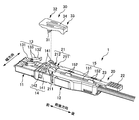
- FIG. 2 is a perspective view of the optical connector 1 and an adapter 40.
- FIG. 2 is an exploded perspective view of the optical connector 1.
- FIG. 3A is a perspective view of the front end portion 21 of the tab 20, and
- FIG. 3B is a perspective view of the rotating member 30 cut at the center in the width direction.
- FIG. 9 is an explanatory diagram of an operation of attaching the optical connector 1 to the adapter 40.
- 5A to 5E are explanatory diagrams of the operation of pulling out the optical connector 1 from the adapter 40. It is a figure showing the state where latch release member 5 was attached to optical connector 4 of a 2nd embodiment.
- FIG. 7A is a perspective view of the optical connector 4, and
- FIG. 7B is an exploded perspective view of the latch release member 5.
- FIG. 8A is an explanatory diagram of a state where the cover unit 122 is closed, and FIG. 8B is an explanatory diagram of a state where the cover unit 122 is opened. It is an exploded perspective view of the optical connector 6 of a third embodiment.
- FIG. 10A is a perspective view of the optical connector 8 of the fourth embodiment, and FIG. 10B is an exploded perspective view of the optical connector 8.
- FIG. 11A is an explanatory diagram of the upper surface of the housing 10, and FIG. 11B is an explanatory diagram of the mounting member 80.
- 12A and 12B are views showing a method of assembling the housing 10 and the mounting member 80.
- 13A and 13B are explanatory views of the stopper 87.
- FIG. 14A and 14B are views showing the engagement between the housing 10 and the mounting member 80.
- An optical connector having a ferrule, a housing containing the ferrule and a latch portion that engages with an adapter, and a tab, comprising a rotating member rotatably supported with respect to the housing.
- the tab moves rearward, the front end of the tab pushes up the rear end of the rotating member, the rotating member rotates, and the front end of the rotating member pushes down the latch portion.
- An optical connector characterized by the above will become apparent.
- the latch portion can be pushed down by the pulling force of the tab. Further, since the tab pushes down the latch portion by pushing up the rotating member, the tab is hardly lifted and detached.
- the front end of the tab has an inclined surface inclined upward toward the front side, and when the tab moves to the rear side, the inclined surface preferably pushes up the rear end of the rotating member. . Thereby, the tab can be smoothly moved to the rear side while pushing up the rotating member.
- the inclined surface has a first inclined surface and a second inclined surface that is steeper than the first inclined surface.
- the first inclined surface rotates.
- the second inclined surface pushes up the rear end of the rotating member after pushing up the rear end of the member. Thereby, the tab can be smoothly moved to the rear side while reducing the length of the inclined surface in the front-rear direction.
- the front end of the tab has the first inclined surface and the second inclined surface arranged in the width direction.
- the contact surface of the rotating member that comes into contact with the inclined surface of the tab can be a surface corresponding to the inclination of the tab.
- the contact surface of the rotating member that contacts the inclined surface is a curved surface that is convex toward the inclined surface. This makes it difficult for the inclined surface of the tab to be caught by the rotating member, and the tab can be smoothly moved to the rear side.
- the two ferrules be a double optical connector arranged in the width direction, and that one rotating member pushes down a pair of the latch portions provided for each of the ferrules. Thereby, the configuration of the optical connector can be simplified.
- the tab is insertable into the adapter by pushing the housing forward.
- the optical connector can be inserted into the adapter by the force pressing the tab.
- the housing has a base portion and a cover portion, and the cover portion can be opened and closed upward with respect to the base portion on a rear side of the rotating member, and the cover portion is open.
- the engaging portion of the cover portion engages with the engaged portion of the rotating member, and the rotation of the rotating member is restricted. Thereby, unnecessary rotation of the rotating member can be suppressed.
- the mounting member is attached to the housing by having a groove along the width direction, wherein the protrusion is slid and inserted into the groove. Thereby, detachment of the mounting member from the housing can be suppressed.
- the position of the housing with respect to the mounting member is fixed by engaging the engaged portion of the housing with the engaging portion of the mounting member.
- the housing can be mounted at an appropriate position in the width direction of the mounting member. Further, the detachment of the mounting member from the housing can be suppressed.
- the two housings are mounted side by side in the width direction on one mounting member. Thereby, the configuration of the optical connector can be simplified.
- the housing has a second protrusion protruding upward from an upper surface, and the mounting member has a stopper at a center portion in the width direction, and the second protrusion contacts the stopper, It is preferable that movement of the housing in the width direction with respect to an attachment member is restricted. Thereby, the housing can be mounted at an appropriate position in the width direction of the mounting member.
- An optical connector having a ferrule, a housing having a latch portion that receives the ferrule and engages with an adapter, a detachable latch release member, and an attaching member detachably attached to the housing;
- a rotating member rotatably supported by the mounting member, and a tab, and when the tab moves rearward, the front end of the tab pushes up the rear end of the rotating member,
- a latch release member is characterized in that the pivot member pivots and the front end of the pivot member depresses the latch. According to such a latch release member, the latch portion can be pushed down by the pulling force of the tab. Further, since the tab pushes down the latch portion by pushing up the rotating member, the tab is hardly lifted and detached.
- FIG. 1 is a perspective view of the optical connector 1 and the adapter 40.
- FIG. 2 is an exploded perspective view of the optical connector 1.
- FIG. 3A is a perspective view of the front end 21 of the tab 20, and
- FIG. 3B is a perspective view of the rotating member 30 cut at the center in the width direction.
- a double LC connector duplex type in which two LC connectors are configured as one set will be described as an example of the optical connector 1.
- the optical connector 1 includes a pair of ferrules 3 for holding an optical fiber, a housing 10 for housing the ferrule 3, a tab 20, and a rotating member 30 rotatably supported with respect to the housing 10.
- the optical connector 1 is attached to a terminal of the optical cable 2 and connects an optical fiber.
- the optical cable 2 has a configuration in which two coated optical fibers and a strength member (not shown) are covered with a jacket.
- the direction in which the optical fiber extends is referred to as “front-back direction”, the side where the ferrule 3 is located is “front”, and the opposite side is “rear”.
- the direction in which the tabs 20 are placed on the housing 10 is referred to as “up-down direction”, the side on which the tabs 20 are located is “up”, and the opposite side is “down”.
- the direction orthogonal to the front-rear direction and the up-down direction is referred to as the “width direction”.
- the housing 10 has a pair of front housings 11 and a rear housing 12. Latch portions 13 are provided on upper surfaces of the pair of front housings 11, respectively. On the upper surface of the rear housing 12, there are provided a fulcrum part 14 for rotatably supporting the rotating member 30, and a tab holding part 15 for holding the tab 20 behind the fulcrum part 14.
- the latch unit 13 is a part for latching the optical connector 1 to the adapter 40.
- the latch portion 13 has a front end 131 fixed to the front housing 11, a rear end 132 separated upward from the front housing 11, and a width between the front end 131 and the rear end 132. And an engaging portion 133 protruding to both outer sides in the direction.
- the latch portion 13 has a cantilever structure, and the rear end portion 132 is elastically restored after being pushed down.
- the engaging portion 133 is a portion that engages with the recess of the adapter 40.
- the fulcrum 14 is a part that rotatably supports the rotating member 30 on the upper surface of the housing 10.
- the fulcrum part 14 has a support part 141 fixed to the rear housing 12 and a bearing part 142 provided on the support part 141. In FIG. 2, three support portions 141 are arranged in the width direction, but the number of the support portions 141 is not limited to this.
- the bearing part 142 is a hole which the support part 141 dented in the width direction or a penetrated hole.
- the rotating member 30 is provided with a shaft portion 31 protruding in the width direction. When the shaft portion 31 is fitted to the bearing portion 142, the rotating member 30 is rotatably supported by the fulcrum portion 14 (that is, the housing 10).
- the tab holding portion 15 is for attaching the tab 20 to the rear housing 12 while allowing the tab 20 to move in the front-rear direction.
- the tab holding section 15 has a guide section 151 and a claw section 152.
- the guide part 151 is a pair of members extending in the front-rear direction.
- the pair of guide portions 151 are spaced apart in the width direction according to the width of the tab 20.
- the claw portion 152 is a portion that protrudes upward from the guide portion 151 and has a tip portion bent inward in the width direction. The claw 152 presses the side end of the tab 20 from above.
- the tab 20 is a member operated by an operator when attaching and detaching the optical connector 1 to and from the adapter 40.
- the tab 20 has a front end 21, an operation unit 22 (rear end) that is gripped and operated by an operator, and a connection unit 23 that connects the front end 21 and the operation unit 22.
- the connecting portion 23 of the tab 20 is held by the tab holding portion 15.
- the front end 21 of the tab 20 has a pair of first inclined portions 211 and a second inclined portion 212, as shown in FIG. 3A.
- the second inclined part 212 is located between the pair of first inclined parts 211 arranged in the width direction.
- the shape of the first inclined portion 211 and the second inclined portion 212 as viewed in the width direction is substantially triangular, and a part of the surface facing the rear side becomes inclined surfaces 211a and 212a inclined upward toward the front side. ing.
- the inclined surface 212a of the second inclined portion 212 (hereinafter also referred to as a second inclined surface) has a steeper inclination than the inclined surface 211a of the first inclined portion 211 (hereinafter also referred to as a first inclined surface). . That is, the angle formed between the lower surface of the tab 20 and the second inclined surface 212a is large.
- the turning member 30 is a substantially plate-shaped member, and turns around a shaft portion 31 provided at the center in the front-rear direction. That is, the front end portion 32 and the rear end portion 33 of the rotating member 30 can move in the vertical direction.
- the front end portion 32 of the rotating member 30 has a front facing surface 32a that can face and contact the rear end portion 132 of the latch portion 13. When the front end 32 of the rotating member 30 is lowered, the front facing surface 32 a pushes down the rear end 132 of the latch 13.
- the rear end portion 33 of the rotating member 30 is capable of facing the first inclined surface 211a of the tab 20 and capable of contacting with the first inclined surface 211a of the tab 20, and is capable of opposing and contacting the second inclined surface 212a of the tab 20. And a second rear facing surface 33b. As the inclined surfaces 211a and 212a of the tab 20 move in the front-rear direction, the rear end 33 of the rotating member 30 moves up and down.
- the first rear facing surface 33a and the second rear facing surface 33b of the rotating member 30 are aligned with the inclined surfaces 211a and 212a of the tab 20. That is, the second rear facing surface 33b is located between the pair of first rear facing surfaces 33a arranged in the width direction.
- the lower end of the turning member 30 is notched upward on the front side of the first rear facing surface 33a so that the first inclined portion 211 of the tab 20 does not buffer the turning member 30.
- a space 34 is provided on the front side of the second rear facing surface 33b so as to vertically penetrate the rotating member 30 so that the second inclined portion 212 of the tab 20 does not buffer the rotating member 30. I have.
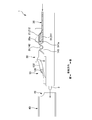
- FIG. 4 is a diagram illustrating an operation of attaching the optical connector 1 to the adapter 40.
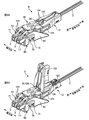
- 5A to 5E are diagrams illustrating the operation of pulling out the optical connector 1 from the adapter 40.
- a part of the optical connector 1 is schematically shown.
- 5A to 5E the adapter 40 is omitted.
- the rear end 132 of the latch portion 13 is pushed down and bent to the upper inside surface of the insertion opening 41 of the adapter 40.
- the latch 13 attempts to recover to its original state by its own elastic force.
- the engaging portion 133 of the latch portion 13 is caught by a recess (not shown) of the adapter 40, and the latch portion 13 enters a latch state. In the latch state, the engagement of the optical connector 1 from the adapter 40 is restricted by the engaging portion 133.
- the second inclined surface 212a which is steeper than the first inclined surface 211a, does not contact the rotating member 30. This is because the second rear facing surface 33b of the rotating member 30 facing the second inclined surface 212a is located rearward and above the first rear facing surface 33a.
- the second inclined surface 212a of the tab 20 contacts the second rear facing surface 33b of the rotating member 30 as shown in FIGS. 5D and 5E. Move to the back side. Then, the second rear facing surface 33b of the rotating member 30 is gradually pushed upward along the second inclined surface 212a. Since the second inclined surface 212a is steeper than the first inclined surface 211a, the push-up amount of the rotating member 30 with respect to the amount of movement of the tab 20 in the front-rear direction increases. When the rear end 33 of the rotating member 30 is further pushed up in this manner, the front end 32 of the rotating member 30 further pushes down the latch portion 13, and the engaging portion 133 of the latch portion 13 comes out of the recess of the adapter 40.
- the inclined surfaces 211a and 212a of the tab 20 push up the rear end 33 of the rotating member 30 and push the rotating member 30 rearward. Therefore, when the engaging portion 133 of the latch portion 13 comes out of the concave portion of the adapter 40 and the latched state is released, the rotating member 30 pushed by the tab 20 moves rearward.
- the housing 10 to which the rotating member 30 is fixed also moves rearward (that is, the entire optical connector 1). Thus, the optical connector 1 can be pulled out of the adapter 40.
- the latch portion 13 pushes up the front end portion 32 of the rotating member 30 by the elastic recovery force of the latch portion 13 which has been pushed down, and the rotating member 30 Rotates in the opposite direction. Then, the rear end 33 of the rotating member 30 pushes the tab 20 forward while falling along the inclined surfaces 211a and 212a of the tab 20. Then, as shown in FIG. 5A, the latch portion 13 returns to the natural state, and the tab 20 moves forward and returns to the original position.
- the latch portion 13 can be pushed down by the force pulling the tab 20 in the front-rear direction, and the tab 20 functions as a “push tab”. Therefore, the optical connector 1 can be easily pulled out from the adapter even when the optical connector 1 is mounted at high density and it is difficult for a worker's finger to enter the optical connector 1.
- the tab end portion is likely to be lifted. In order to suppress the lifting of the tab, it is necessary to add a complicated mechanism or an operator to strongly pull the tab.
- the tab 20 pushes up the rotating member 30, and the rotating member 30 pushes down the latch portion 13. Therefore, the tab 20 is unlikely to rise, and the tab 20 is unlikely to come off the housing 10.
- the tab 20 supports the rotating member 30 from below while pushing it up. Therefore, the tab 20 can easily resist the return of the rotating member 30 due to the elastic recovery force of the latch portion 13. Therefore, in the optical connector 1 of the present embodiment, there is no need for the operator to pull the tab 20 strongly as in the case where the end of the tab is directly connected to the latch portion.
- the rotating member 30 also functions as a “lever” having the shaft portion 31 as a fulcrum, the rear end portion 33 in contact with the tab 20 as a power point, and the front end portion 32 for pushing down the latch portion 13 as an action point. Therefore, even if the small force for pulling the tab 20 is small, the tab 20 pushes up the rear end 33 of the rotating member 30 by the principle of leverage, and the rotating member 30 resists the recovery force of the latch portion 13. Can be pushed down.
- the surface of the tab 20 that pushes up the rear end portion 33 of the rotating member 30 when the tab 20 moves rearward is preferably inclined surfaces 211a and 212a. By doing so, the tab 20 can gradually push up the rotating member 30. In addition, the smooth inclined surfaces 211a and 212a having no steps are hardly caught by the rotating member 30. Therefore, the resistance of the rotating member 30 against the rearward movement of the tab 20 can be reduced, and the tab 20 can smoothly move rearward while pushing up the rotating member 30. Therefore, the latch 13 can be pushed down even if the pulling force of the tab 20 is small.
- the surface of the tab 20 that pushes up the rear end 33 of the rotating member 30 may be a first inclined surface 211a and a second inclined surface 212a whose inclination is steeper than the first inclined surface 211a.
- first inclined surface 211a pushes up the rear end 33 of the rotating member 30, and then the second inclined surface 212a pushes up the rear end 33 of the rotating member 30. preferable.
- the rotating member 30 is pushed up only by the first inclined surface 211a having a gentle inclination, the pushing amount of the rotating member 30 with respect to the moving amount of the tab 20 in the front-back direction is small, and the front-back direction of the first inclined portion 211 is small. Must be lengthened. Conversely, if the rotating member 30 is pushed up from the beginning on the steeply inclined second inclined surface 212a, the resistance of the rotating member 30 against the rearward movement of the tab 20 is large, and the tab 20 moves rearward. It will be difficult to do. Then, the operator may pull the tab 20 forcibly, and the tab 20 may be damaged.
- the gently inclined first inclined surface 211a comes into contact with the rotating member 30, and the tab 20 starts to move smoothly to the rear side. It is good to push up greatly. By doing so, the tab 20 can be smoothly moved rearward while the length of the inclined portions 211 and 212 of the tab 20 in the front-rear direction is reduced.
- the first inclined surface 211a and the second inclined surface 212a are arranged in the width direction.
- the surface of the rotating member 30 that contacts the first inclined surface 211a that is, the first rear facing surface 33a
- the surface of the rotating member 30 that contacts the second inclined surface 212a that is, the second rear surface
- the side facing surface 33b) can be different. Therefore, the first rear-side facing surface 33a and the second rear-side facing surface 33b of the rotating member 30 are changed to a surface corresponding to the inclination of the inclined surfaces 211a and 212a that come into contact, that is, a surface where the inclined surfaces 211a and 212a are hard to be caught. can do.
- the first rear facing surface 33a is more gradually inclined forward than the second rear facing surface 33b. Therefore, the first rear facing surface 33a is easily opposed to the vertical direction of the first inclined surface 211a, and the second rear facing surface 33b is easily opposed to the vertical direction of the second inclined surface 212a. Therefore, the inclined surfaces 211a and 212a are hardly caught by the rotating member 30, and the tab 20 can be smoothly moved to the rear side.
- the tab 20 may have only one of the first inclined surface 211a and the second inclined surface 212a.
- a form in which one inclined portion has the first inclined surface 211a and the second inclined surface 212a may be employed. That is, the second inclined surface 212a may be continuously located in front of the first inclined surface 211a.
- the first rear facing surface 33a and the second rear facing surface 33b (contacted surfaces) of the rotating member 30 are preferably curved surfaces that are convex toward the inclined surfaces 211a and 212a. By doing so, even if the rotation member 30 rotates and the inclination changes, the inclined surfaces 211a and 212a are hardly caught by the rotation member 30, and the tab 20 can be smoothly moved to the rear side.
- the mounting position in the width direction of the tab 20 with respect to the housing 10 and the rotating member 30 is determined. Therefore, the first inclined surface 211a of the tab 20 can be brought into contact with the first rear facing surface 33a of the rotating member 30, and the second inclined surface 212a of the tab 20 can be brought into contact with the second rear facing surface of the rotating member 30. 33b.
- the latch state of the latch portion 13 can be released also by the operator pressing down the front end portion 32 of the rotating member 30 with a finger. That is, both the method of pulling out the optical connector 1 from the adapter 40 using the tab 20 and the method of pulling out the optical connector 1 from the adapter 40 without using the tab 20 can be implemented. Therefore, the degree of freedom of work is high.
- the optical connector 1 of the present embodiment is a double optical connector in which two ferrules 3 are arranged in the width direction.
- one rotating member 30 is provided for a pair of latch portions 13 provided for each ferrule 3, and the pair of latch portions 13 is pushed down by one rotating member 30.
- the configuration of the optical connector 1 can be simplified as compared with a case where, for example, the rotating member 30 is provided for each latch unit 13. Also, when the operator presses down the rotating member 30 with a finger to release the latched state, the latched state of the pair of latch portions 13 can be released easily and simultaneously, thereby improving workability.
- the present invention is not limited to the above, and a rotating member 30 may be provided for each latch unit 13.
- the tab 20 can be inserted into the adapter 40 by pushing the housing 10 forward. That is, the tab 20 is preferably a “push-pull tab”. By doing so, the optical connector 1 can be easily mounted on the adapter 40 even when the optical connector 1 is mounted at a high density and it is difficult for the operator's finger to enter between the optical connectors 1.
- the front end face 20a of the tab 20 pushes the rear end face 141a of the support 141 toward the front.
- the present invention is not limited to this, and it is sufficient that any part of the tab 20 can push any part of the housing 10 forward.
- the tab 20 is not limited to a push-pull tab, and the tab 20 may not be used when inserting the optical connector 1 into the adapter 40.
- FIG. 6 is a diagram illustrating a state where the latch release member 5 is attached to the optical connector 4 of the second embodiment.
- FIG. 7A is a perspective view of the optical connector 4.
- FIG. 7B is an exploded perspective view of the latch release member 5.
- the latch release member 5 can be attached to and detached from the existing optical connector 1 having the ferrule 3 and the housing 10 that accommodates the ferrule 3 and has the latch portion 13 that engages with the adapter.
- an LC connector having one ferrule 3 is illustrated, but a latch release member detachable from a housing of two LC connectors may be used.
- the latch release member 5 includes a mounting member 50 detachably mounted on the housing 10, a rotating member 30 rotatably supported by the mounting member 50, and a tab 20.
- the tab 20 and the rotating member 30 have the same configuration as in the first embodiment.
- the tab 20 has a pair of engaging portions 213 that protrude to both outer sides in the width direction of the pair of first inclined portions 211 and engage with the mounting member 50.
- the attachment member 50 is a member that is detachably attached to the rear housing 12 of the optical connector 4 and is a member having an inverted U-shaped cross section having a pair of side surfaces 51 and an upper surface 52.
- the rear housing 12 is inserted into a space 501 surrounded by the pair of side surfaces 51 and the upper surface 52.
- the lower end portions of the pair of side surface portions 51 are claw portions 502 that are bent inward in the width direction, and the detachment of the rear housing 12 from the mounting member 50 is restricted.
- a pair of fulcrum portions 503 projecting upward from both sides in the width direction are provided on the upper surface portion 52.
- the fulcrum 503 is provided with a bearing 504 (hole).
- a pair of side plate portions 505 protruding upward from both side portions in the width direction and a horizontal plate portion connecting the front ends of the pair of side plate portions 505 in the width direction, behind the fulcrum portion 503. 506 are provided.
- a pair of side plate portions 505 are provided with engagement holes 507 that are long in the front-rear direction, and the engagement portions 213 of the tab 20 are engaged with the engagement holes 507.
- the tab 20 is attached to the attachment member 50 so as to be movable in the front-rear direction. Further, when the tab 20 pushes the horizontal plate portion 506 forward, the mounting member 50 and the optical connector 4 move forward, and the optical connector 4 can be inserted into the adapter.
- the latch release member 5 of the present embodiment does not directly connect the end of the tab to the latch portion 13, it can be easily attached to the existing optical connector 4.
- FIG. 8A is an explanatory diagram of a state where the cover 122 of the rear housing 12 is closed
- FIG. 8B is an explanatory diagram of a state where the cover 122 is open
- FIG. 9 is an exploded perspective view of the optical connector 6 according to the third embodiment.
- the optical connector 6 of the third embodiment is a field-assembled optical connector for connecting optical fibers by a mechanical splice method.
- the optical connector 6 according to the third embodiment includes an optical connector main body 7 (for example, the optical connector 1 described in the first embodiment), a mechanical splice portion (not shown), an insertion member 60, and a fixing member 70. Have.
- the mechanical splice portion is housed in the front housing 11 and is used for connecting optical fibers by butt-connecting. More specifically, the optical fiber 2A inserted from the outside and attached to the rear side of the ferrule 3 and the optical fiber previously held in the ferrule 3 are connected by butt.
- the insertion member 60 is for opening and closing the gap between the mechanical splices, and is a U-shaped member having a pair of side surfaces 61 and a lower surface 62 as shown in FIG.
- the lower surface portion 62 is provided with an insertion piece 63 (wedge) projecting upward.
- An insertion hole (not shown) is formed on the lower surface of the front housing 11 (optical connector body 7).
- the insertion member 60 is attached below the housing 10 so that the insertion piece 63 is inserted into the insertion hole.
- the pair of side surfaces 61 are provided with through holes 64 for allowing the fixing member 70 to penetrate in the width direction.
- the fixing member 70 is for fixing the insertion member 60 to the housing 10 in a detachable manner.
- the insertion member 60 is fixed to the housing 10 by inserting the fixing member 60 into the through hole 64 of the insertion member 60.
- the length of the one end 71 of the fixing member 70 in the front-rear direction is longer than the length of the through hole 64 in the front-rear direction. Therefore, the detachment of the fixing member 70 from the through hole 64 is suppressed.
- the other end of the fixing member 70 is a pair of elastic plates 72 branched in a V shape. When the worker releases the hand after passing the fixing member 70 through the through hole 64 while approaching the pair of elastic plates 72, the elastic plate 72 contacts the insertion member 60. Further, tips 721 of the pair of elastic plates 72 protrude in the front-rear direction. Therefore, the detachment of the fixing member 70 from the through hole 64 is suppressed. As described above, the fixing member 70 is hard to come off from the insertion member 60, and the insertion member 60 is firmly fixed to the housing 10.
- the fixing member 70 inserted into the through hole 64 of the insertion member 60 is located between the latch 13 and the upper surface of the housing 10. Therefore, even if the rotating member 30 is unnecessarily rotated to push down the latch portion 13 before the optical connector main body 7 is mounted on the adapter, the latch portion 13 contacts the fixing member 70 and moves downward from the latch portion 13. Movement is regulated. In other words, unnecessary rotation of the rotating member 30 can be restricted. Therefore, breakage of the latch portion 13 and detachment of the rotating member 30 can be suppressed.
- the rear housing 12 has the base 121 and the cover 122, and the holding member 123 is accommodated in the base 121.
- the cover portion 122 can be opened and closed upward with respect to the base portion 121 behind the rotating member 30.
- the operator causes the gripping member 123 to grip the jacket of the optical cable 2 with the cover 122 opened. Further, the worker extends the optical fiber 2A drawn out of the optical cable 2 to the front side of the gripping member 123 and inserts the optical fiber 2A into the mechanical splice.
- the cover part 122 has a pair of engaging parts 124 arranged in the width direction on the upper surface.
- the rotating member 30 has a pair of engaged portions 35 projecting outward from both sides in the width direction.
- FIG. 10A is a perspective view of the optical connector 8 of the fourth embodiment
- FIG. 10B is an exploded perspective view of the optical connector 8.
- FIG. 11A is an explanatory diagram of the upper surface of the housing 10
- FIG. 11B is an explanatory diagram of the mounting member 80.
- 12A and 12B are views showing a method of assembling the housing 10 and the mounting member 80.
- 13A and 13B are explanatory views of the stopper 87.
- FIG. 14A and 14B are views showing the engagement between the housing 10 and the mounting member 80.
- the optical connector 8 includes the ferrule 3, the housing 10, the tab 20, the turning member 30, and the mounting member 80.
- the tab 20 and the rotating member 30 have the same configuration as in the first embodiment. That is, as shown in FIG. 11B, the tab 20 has an inclined surface 21a inclined upward toward the front side.
- the rotating member 30 has a surface 33c that contacts the inclined surface 21a of the tab 20 and a surface 32b that contacts the latch portion 13.
- the number of the inclined surfaces 21a of the tab 20 illustrated in FIG. 11B is one, but may be two or more.
- the housing 10 has the same configuration as the housing 10 of the first embodiment, accommodates the ferrule 3, and includes the latch portion 13. However, as shown in FIG. 11A, the housing 10 of the fourth embodiment has a protrusion 16 and a second protrusion 17 that protrude upward from the upper surface.
- the second protrusion 17 is provided on the front side of the protrusion 16.
- an engagement protrusion 18 protruding upward is provided on the upper surface of the protrusion 16.
- the mounting member 80 has a pedestal 81 and a pair of side surfaces 82 projecting upward from both side portions of the pedestal 81 in the width direction.
- the side surface portion 82 is provided with a bearing portion 83 (hole).
- the mounting member 80 has a groove 84 having an inverted L-shaped cross section dug upward from the lower surface of the pedestal 81.
- the groove portion 84 is long in the width direction and penetrates from the side surface portion 82 on one side in the width direction to the side surface portion 82 on the other side.
- the cross-sectional shape of the groove 84 is the same as the cross-sectional shape of the protrusion 16 of the housing 10, and the protrusion 16 can be inserted into the groove 84.
- a pair of engagement holes 85 penetrating in the up-down direction is provided in the portion of the pedestal 81 above the groove portion 84. That is, the engagement hole 85 communicates with the groove 84.
- a hole 86 is provided in the side surface portion 82 behind the groove portion 84 so that the widthwise side portions 214 of the front end portion 21 of the tab 20 are engaged with each other. Attached to 80. Further, a stopper 87 is provided at the center in the width direction at the front end of the mounting member 80.
- the front end surface 21 b of the tab 20 can push a portion 88 protruding inward in the width direction from the side surface portion 82 of the mounting member 80 toward the front side. As a result, the housing 10 is pushed forward. Therefore, the tab 20 of the fourth embodiment also functions as a “push-pull tab”.
- FIG. 12B the operator inserts the protrusion 16 of another housing 10 from the other side in the width direction into the groove 84 of the attachment member 80 and slides the same in the width direction. By doing so, another housing 10 is attached to the attachment member 80.
- FIG. 10A a double optical connector 8 in which two housings 10 are attached to one attachment member 80 is completed.
- the mounting member 80 is attached to the housing 10 by slidingly inserting the protrusion 16 of the housing 10 into the groove 84 along the width direction of the mounting member 80.
- optical connector 8 of the fourth embodiment two housings 10 are attached to one attachment member 80 side by side in the width direction. Further, one tab 20 and one rotating member 30 are also attached to the two housings 10, respectively. Therefore, the configuration of the optical connector 8 can be simplified as compared with the case where the mounting member 80 and the like are provided for each housing 10. In addition, the operator can simultaneously release the two latch portions 13 by pressing down the rotating member 30 with a finger, thereby improving workability.
- the latch 13 of the housing 10 according to the fourth embodiment can be pushed down by the operator's finger. Therefore, the housing 10 of the fourth embodiment can be used as a single LC connector. In addition, as described above, by using the attachment member 80, the two housings 10 can be integrated and used as a double LC connector, and the usage is wide.
- the housing 10 When two housings 10 are mounted on one mounting member 80, the housing 10 has the second protrusion 17 as shown in FIG. 11A, and the mounting member 80 has a stopper as shown in FIG. 11B. It is preferred to have 87. By doing so, for example, as shown in FIG. 13A, when mounting the housing 10 from the other side in the width direction of the mounting member 80, as shown in FIG. The surface contacts the other surface in the width direction of the stopper 87. Similarly, when another housing 10 is mounted from one side in the width direction of the mounting member 80, the second projecting portion 17 of another housing 10 comes into contact with the stopper 87.
- the housing 10 is mounted at an appropriate position in the width direction of the mounting member 80. Can be. Therefore, the two housings 10 are integrated at an appropriate interval without being too separated or too close.
- the length in the width direction is shorter than that of the protrusion 16.
- the second protrusion 17 is preferably arranged at the center of the housing 10 in the width direction so that the housing 10 can be attached to the mounting member 80 from one side or the other side in the width direction.
- the position of the housing 10 with respect to the mounting member 80 be fixed by engaging the engaged portion of the housing 10 with the engaging portion of the mounting member 80.
- the engagement protrusion 18 (engaged portion) of the housing 10 shown in FIG. 11A engages with the engagement hole 85 (engagement portion) of the attachment member 80 shown in FIG. 11B.
- the engagement projections 18 of the housing 10 engage with the engagement holes 85 of the attachment member 80. Then, the movement of the housing 10 is regulated.
- the housing 10 can be mounted at an appropriate position in the width direction of the mounting member 80. Further, when the tab 20 is pulled or the like, the detachment of the attachment member 80 from the housing 10 can be suppressed.
- the present invention is not limited thereto, and the engaged portion of the housing 10 may be engaged with the engaging portion of the mounting member 80.
- the engaging portion of the mounting member 80 The portion may be an engagement hole.
- the optical connector may be such that one housing 10 can be attached to the attachment member 80 of the fourth embodiment. Further, a form without the second protrusion 17 of the housing 10 and the stopper 87 of the mounting member 80 or a form without the engaging hole 85 of the mounting member 80 and the engaging protrusion 18 of the housing 10 may be used.
- the LC connector is exemplified as the optical connector, but the present invention is not limited to the LC connector as long as the optical connector includes a latch unit, and the present invention can be applied.
Landscapes
- Physics & Mathematics (AREA)
- General Physics & Mathematics (AREA)
- Optics & Photonics (AREA)
- Mechanical Coupling Of Light Guides (AREA)
Abstract
【課題】タブを引っ張る力によってラッチ部を押し下げることを可能にしつつ、タブを外れ難くするための新規な構成を提供する。 【解決手段】本開示に係る光コネクタは、フェルールと、フェルールを収容し、アダプタに係合するラッチ部を備えるハウジングと、タブと、を有する。この光コネクタは、ハウジングに対して回動可能に支持された回動部材を有する。タブが後側に移動すると、タブの前端部が回動部材の後端部を押し上げて、回動部材が回動し、回動部材の前端部がラッチ部を押し下げる。
Description
本発明は、光コネクタ、及び、ラッチ解除部材に関する。
光コネクタとして、いわゆるLCコネクタが知られている。LCコネクタでは、ハウジングの前部にラッチ部が形成されている。LCコネクタの抜去時には、ラッチ部を押し下げて光コネクタのラッチを解除しつつ、光コネクタを引き抜くことになる。特許文献1には、LCコネクタのラッチを解除する機構が記載されている。
また、光コネクタを高密度に実装する場合には、光コネクタ間に作業者の指が入りにくくなり、光コネクタのラッチを解除する作業が困難になることがある。そこで、特許文献2には、光コネクタの挿抜作業をしやすくするためのタブ(プッシュプルタブ)を光コネクタに取り付けることが記載されている。
また、光コネクタを高密度に実装する場合には、光コネクタ間に作業者の指が入りにくくなり、光コネクタのラッチを解除する作業が困難になることがある。そこで、特許文献2には、光コネクタの挿抜作業をしやすくするためのタブ(プッシュプルタブ)を光コネクタに取り付けることが記載されている。
特許文献2に記載の光コネクタは、いわゆるMPOコネクタであるため、ラッチを解除させるためにカップリングに作用させる力の方向と、タブを引っ張る方向とが一致している。このため、タブをカップリングに連結させ、タブを引っ張れば、光コネクタのラッチを解除させることができる。
これに対し、LCコネクタの場合、光コネクタのラッチを解除させるためにラッチ部に作用させる方向(押し下げる方向)と、タブを引っ張る方向とが異なっている。このため、仮に、タブの端部をラッチ部に連結させて、タブを引っ張る力によってラッチ部を押し下げようとすると、タブの端部が浮き上がってしまい、タブが光コネクタの本体から外れ易くなってしまう。
これに対し、LCコネクタの場合、光コネクタのラッチを解除させるためにラッチ部に作用させる方向(押し下げる方向)と、タブを引っ張る方向とが異なっている。このため、仮に、タブの端部をラッチ部に連結させて、タブを引っ張る力によってラッチ部を押し下げようとすると、タブの端部が浮き上がってしまい、タブが光コネクタの本体から外れ易くなってしまう。
本発明は、タブを引っ張る力によってラッチ部を押し下げることを可能にしつつ、タブを外れ難くするための新規な構成を提供することを目的とする。
本発明の幾つかの実施形態は、フェルールと、前記フェルールを収容し、アダプタに係合するラッチ部を備えるハウジングと、タブと、を有する光コネクタであって、前記ハウジングに対して回動可能に支持された回動部材を有し、前記タブが後側に移動すると、前記タブの前端部が前記回動部材の後端部を押し上げて、前記回動部材が回動し、前記回動部材の前端部が前記ラッチ部を押し下げることを特徴とする光コネクタである。
本発明の他の特徴については、後述する明細書及び図面の記載により明らかにする。
本発明の幾つかの実施形態によれば、タブを引っ張る力によってラッチ部を押し下げることを可能にしつつ、タブを外れ難くするための新規な構成を提供することができる。
後述する明細書及び図面の記載から、少なくとも以下の事項が明らかとなる。
フェルールと、前記フェルールを収容し、アダプタに係合するラッチ部を備えるハウジングと、タブと、を有する光コネクタであって、前記ハウジングに対して回動可能に支持された回動部材を有し、前記タブが後側に移動すると、前記タブの前端部が前記回動部材の後端部を押し上げて、前記回動部材が回動し、前記回動部材の前端部が前記ラッチ部を押し下げることを特徴とする光コネクタが明らかとなる。
このような光コネクタによれば、タブを引っ張る力によってラッチ部を押し下げることができる。また、タブが回動部材を押し上げることによってラッチ部を押し下げるため、タブが浮き上がり難く、外れ難い。
フェルールと、前記フェルールを収容し、アダプタに係合するラッチ部を備えるハウジングと、タブと、を有する光コネクタであって、前記ハウジングに対して回動可能に支持された回動部材を有し、前記タブが後側に移動すると、前記タブの前端部が前記回動部材の後端部を押し上げて、前記回動部材が回動し、前記回動部材の前端部が前記ラッチ部を押し下げることを特徴とする光コネクタが明らかとなる。
このような光コネクタによれば、タブを引っ張る力によってラッチ部を押し下げることができる。また、タブが回動部材を押し上げることによってラッチ部を押し下げるため、タブが浮き上がり難く、外れ難い。
前記タブの前記前端部は、前側に向かって上方に傾斜した傾斜面を有し、前記タブが後側に移動すると、前記傾斜面は、前記回動部材の前記後端部を押し上げることが望ましい。
これにより、タブは回動部材を押し上げつつ、スムーズに後側に移動できる。
これにより、タブは回動部材を押し上げつつ、スムーズに後側に移動できる。
前記傾斜面は、第1傾斜面と、前記第1傾斜面よりも傾斜が急な第2傾斜面と、を有し、前記タブが後側に移動すると、前記第1傾斜面が前記回動部材の前記後端部を押し上げた後に、前記第2傾斜面が前記回動部材の前記後端部を押し上げることが望ましい。
これにより、前後方向における傾斜面の長さを短くしつつ、タブはスムーズに後側に移動できる。
これにより、前後方向における傾斜面の長さを短くしつつ、タブはスムーズに後側に移動できる。
前記タブの前記前端部は、前記第1傾斜面、及び、前記第2傾斜面を、幅方向に並んで有することが望ましい。
これにより、タブの傾斜面に接触する回動部材の被接触面を、タブの傾斜に応じた面にすることができる。
これにより、タブの傾斜面に接触する回動部材の被接触面を、タブの傾斜に応じた面にすることができる。
前記傾斜面に接触する前記回動部材の被接触面は、前記傾斜面に向かって凸となる湾曲面であることが望ましい。
これにより、タブの傾斜面が回動部材に引っ掛かり難く、タブはスムーズに後側に移動できる。
これにより、タブの傾斜面が回動部材に引っ掛かり難く、タブはスムーズに後側に移動できる。
2つの前記フェルールが幅方向に並んだ2連の光コネクタであり、前記フェルール毎に設けられた一対の前記ラッチ部を、1つの前記回動部材が押し下げることが望ましい。
これにより、光コネクタの構成を簡素化できる。
これにより、光コネクタの構成を簡素化できる。
前記タブは、前記ハウジングを前側に押して前記アダプタに挿入可能であることが望ましい。
これにより、タブを押す力によって、光コネクタをアダプタに挿入できる。
これにより、タブを押す力によって、光コネクタをアダプタに挿入できる。
光ファイバを突き合わせて接続するメカニカルスプライス部と、前記メカニカルスプライス部の隙間を開閉させる介挿部材と、前記介挿部材を前記ハウジングに着脱可能に固定する固定部材と、を有し、前記固定部材は、前記ラッチ部と前記ハウジングの上面との間に設けられることが望ましい。
これにより、回動部材の不要な回動によるラッチ部の下方への移動を抑制できる。
これにより、回動部材の不要な回動によるラッチ部の下方への移動を抑制できる。
前記ハウジングは、ベース部と、カバー部とを有し、前記カバー部は、前記回動部材よりも後側において、前記ベース部に対して上側に開閉可能であり、前記カバー部が開いた状態において、前記カバー部の係合部は前記回動部材の被係合部に係合し、前記回動部材の回動が規制されることが望ましい。
これにより、回動部材の不要な回動を抑制できる。
これにより、回動部材の不要な回動を抑制できる。
前記ハウジングに着脱可能に取り付けられる取り付け部材を有し、前記回動部材及び前記タブは、前記取り付け部材に取り付けられ、前記ハウジングは、上面から上側に突出する突出部を有し、前記取り付け部材は、幅方向に沿った溝部を有し、前記溝部に前記突出部がスライド挿入されることで、前記ハウジングに前記取り付け部材が取り付けられることが望ましい。
これにより、ハウジングに対する取付け部材の抜けを抑制できる。
これにより、ハウジングに対する取付け部材の抜けを抑制できる。
前記取り付け部材の係合部に前記ハウジングの被係合部が係合することで、前記取り付け部材に対する前記ハウジングの位置が固定されることが望ましい。
これにより、取り付け部材における幅方向の適切な位置にハウジングを取り付けることができる。また、ハウジングに対する取付け部材の抜けを抑制できる。
これにより、取り付け部材における幅方向の適切な位置にハウジングを取り付けることができる。また、ハウジングに対する取付け部材の抜けを抑制できる。
1つの前記取り付け部材に、2つの前記ハウジングが前記幅方向に並んで取り付けられることが望ましい。
これにより、光コネクタの構成を簡素化できる。
これにより、光コネクタの構成を簡素化できる。
前記ハウジングは、上面から上側に突出する第2突出部を有し、前記取り付け部材は、前記幅方向の中央部においてストッパを有し、前記第2突出部が前記ストッパに接触することで、前記取り付け部材に対する前記ハウジングの前記幅方向への移動が規制されることが望ましい。
これにより、取り付け部材における幅方向の適切な位置にハウジングを取り付けることができる。
これにより、取り付け部材における幅方向の適切な位置にハウジングを取り付けることができる。
フェルールと、前記フェルールを収容し、アダプタに係合するラッチ部を備えるハウジングと、を有する光コネクタに、着脱可能なラッチ解除部材であって、前記ハウジングに着脱可能に取り付けられる取り付け部材と、前記取り付け部材に回動可能に支持された回動部材と、タブと、を有し、前記タブが後側に移動すると、前記タブの前端部が前記回動部材の後端部を押し上げて、前記回動部材が回動し、前記回動部材の前端部が前記ラッチ部を押し下げることを特徴とするラッチ解除部材が明らかとなる。
このようなラッチ解除部材によれば、タブを引っ張る力によってラッチ部を押し下げることができる。また、タブが回動部材を押し上げることによってラッチ部を押し下げるため、タブが浮き上がり難く、外れ難い。
このようなラッチ解除部材によれば、タブを引っ張る力によってラッチ部を押し下げることができる。また、タブが回動部材を押し上げることによってラッチ部を押し下げるため、タブが浮き上がり難く、外れ難い。
===第1実施形態===
<<光コネクタ1の構成>>
図1は、光コネクタ1及びアダプタ40の斜視図である。図2は、光コネクタ1の分解斜視図である。図3Aは、タブ20の前端部21の斜視図であり、図3Bは、幅方向の中央で切断した回動部材30の斜視図である。第1実施形態では、光コネクタ1として、2つのLCコネクタを1組で構成した2連のLCコネクタ(デュプレックス型)を例に挙げて説明する。
<<光コネクタ1の構成>>
図1は、光コネクタ1及びアダプタ40の斜視図である。図2は、光コネクタ1の分解斜視図である。図3Aは、タブ20の前端部21の斜視図であり、図3Bは、幅方向の中央で切断した回動部材30の斜視図である。第1実施形態では、光コネクタ1として、2つのLCコネクタを1組で構成した2連のLCコネクタ(デュプレックス型)を例に挙げて説明する。
光コネクタ1は、光ファイバを保持する一対のフェルール3と、フェルール3を収容するハウジング10と、タブ20と、ハウジング10に対して回動可能に支持された回動部材30とを有する。光コネクタ1は、光ケーブル2の端末に取り付けられ、光ファイバを接続するためのものである。光ケーブル2は、被覆付きの2本の光ファイバと抗張力体(不図示)とを外被で被覆した構成である。
光コネクタ1において、光ファイバが延びる方向を「前後方向」とし、フェルール3が位置する側を「前」とし、その逆側を「後」とする。また、ハウジング10にタブ20が重ねて配置される方向を「上下方向」とし、タブ20が位置する側を「上」とし、その逆側を「下」とする。また、前後方向と上下方向に直交する方向を「幅方向」とする。
ハウジング10は、一対の前側ハウジング11と、後側ハウジング12とを有する。一対の前側ハウジング11の上面には、それぞれ、ラッチ部13が設けられている。後側ハウジング12の上面には、回動部材30を回動可能に支持する支点部14と、支点部14よりも後側においてタブ20を保持するタブ保持部15とが設けられている。
ラッチ部13は、光コネクタ1をアダプタ40にラッチするための部位である。ラッチ部13は、図2に示すように、前側ハウジング11に固定された前端部131と、前側ハウジング11から上方に離間した後端部132と、前端部131と後端部132の間において幅方向の両外側に突出した係合部133とを有する。ラッチ部13は片持ち梁の構造であり、後端部132は押し下げられた後に弾性回復する。光コネクタ1がアダプタ40に挿入されたとき、係合部133はアダプタ40の凹みに係合する部位である。
支点部14は、ハウジング10の上面で回動部材30を回動可能に支持する部位である。支点部14は、後側ハウジング12に固定された支持部141と、支持部141に設けられた軸受け部142とを有する。図2では、幅方向に支持部141が3つ並んでいるが、支持部141の数はこれに限定されない。軸受け部142は、支持部141が幅方向に凹んだ穴又は貫通した穴である。図3Bに示すように、回動部材30には幅方向に突出した軸部31が設けられている。この軸部31が軸受け部142に嵌合されることで、回動部材30は支点部14(すなわちハウジング10)に回動可能に支持される。
タブ保持部15は、タブ20の前後方向の移動を許容しつつ、タブ20を後側ハウジング12に取り付けるためのものである。タブ保持部15は、ガイド部151と、爪部152とを有する。ガイド部151は、前後方向に延びた一対の部材である。一対のガイド部151は、タブ20の幅長さに合わせて、幅方向に離間して配置されている。爪部152は、ガイド部151から上方に突出し、その先端部が幅方向の内側に折れ曲がった部位である。爪部152は、タブ20の側端を上側から抑え込む。
タブ20は、アダプタ40に対して光コネクタ1を着脱する際に作業者が操作する部材である。タブ20は、前端部21と、作業員に把持されて操作される操作部22(後端部)と、前端部21と操作部22を連結する連結部23とを有する。タブ20の連結部23がタブ保持部15に保持される。
タブ20の前端部21は、図3Aに示すように、一対の第1傾斜部211と、第2傾斜部212とを有する。幅方向に並ぶ一対の第1傾斜部211の間に、第2傾斜部212が位置する。第1傾斜部211及び第2傾斜部212を幅方向に見た形状は略三角形であり、後側に向いた面の一部が、前側に向かって上方に傾斜した傾斜面211a,212aとなっている。第1傾斜部211の傾斜面211a(以下、第1傾斜面ともいう)よりも、第2傾斜部212の傾斜面212a(以下、第2傾斜面ともいう)の方が、傾斜が急である。すなわち、タブ20の下面と第2傾斜面212aとで成す角度が大きくなっている。
回動部材30は、略板状の部材であり、前後方向の中央部に設けられた軸部31を中心に回動する。つまり、回動部材30の前端部32及び後端部33は、上下方向に移動可能である。
回動部材30の前端部32は、ラッチ部13の後端部132と対向して接触可能な前側対向面32aを有する。回動部材30の前端部32が下がると、前側対向面32aがラッチ部13の後端部132を押し下げる。
回動部材30の後端部33は、タブ20の第1傾斜面211aと対向して接触可能な第1後側対向面33aと、タブ20の第2傾斜面212aと対向して接触可能な第2後側対向面33bとを有する。タブ20の傾斜面211a,212aの前後方向の動きに伴って、回動部材30の後端部33は上下方向に動く。
なお、図3Bには示されていないが、回動部材30の第1後側対向面33a及び第2後側対向面33bは、タブ20の傾斜面211a,212aの並びに合わせて並んでいる。つまり、幅方向に並ぶ一対の第1後側対向面33aの間に、第2後側対向面33bが位置する。
また、タブ20の第1傾斜部211が回動部材30と緩衝しないように、第1後側対向面33aよりも前側において、回動部材30の下端部は上方に切り欠かれている。同様に、タブ20の第2傾斜部212が回動部材30と緩衝しないように、第2後側対向面33bよりも前側において、回動部材30を上下方向に貫通する空間34が設けられている。
<光コネクタ1の着脱動作>
図4は、アダプタ40への光コネクタ1の装着動作の説明図である。図5A~図5Eは、アダプタ40からの光コネクタ1の引き抜き動作の説明図である。図面では光コネクタ1の一部を模式的に示す。また、図5A~図5Eではアダプタ40を省略する。
図4は、アダプタ40への光コネクタ1の装着動作の説明図である。図5A~図5Eは、アダプタ40からの光コネクタ1の引き抜き動作の説明図である。図面では光コネクタ1の一部を模式的に示す。また、図5A~図5Eではアダプタ40を省略する。
(1)光コネクタ1の装着動作
作業者は、光コネクタ1の前端部をアダプタ40の挿入口41に挿し込みつつ、タブ20の操作部22を把持して、タブ20を前側に挿し込む。そうすると、図4に示すように、タブ20の前端面20a(詳しくは第2傾斜部212の前端面)が支持部141の後端面141aに接触し、支持部141を前側に押す。そうすると、支持部141が固定されているハウジング10が(すなわち光コネクタ1全体が)アダプタ40の内部に挿し込まれる。
作業者は、光コネクタ1の前端部をアダプタ40の挿入口41に挿し込みつつ、タブ20の操作部22を把持して、タブ20を前側に挿し込む。そうすると、図4に示すように、タブ20の前端面20a(詳しくは第2傾斜部212の前端面)が支持部141の後端面141aに接触し、支持部141を前側に押す。そうすると、支持部141が固定されているハウジング10が(すなわち光コネクタ1全体が)アダプタ40の内部に挿し込まれる。
光コネクタ1がアダプタ40の内部に挿し込まれるにしたがって、アダプタ40の挿入口41の内側上面に、ラッチ部13の後端部132が押し下げられて撓む。光コネクタ1がアダプタ40の適切な位置まで挿し込まれると、ラッチ部13は自身の弾性力により元の状態に回復しようとする。その際に、ラッチ部13の係合部133がアダプタ40の凹み(不図示)に引っ掛かり、ラッチ状態となる。ラッチ状態では、係合部133によってアダプタ40からの光コネクタ1の抜けが規制される。
(2)光コネクタ1の引き抜き動作
作業者は、タブ20の操作部22を把持して、タブ20を後側に引っ張る。そうすると、図5B及び図5Cに示すように、タブ20の第1傾斜面211aは、回動部材30の第1後側対向面33aに接触しながら後側に移動する。そうすると、回動部材30の第1後側対向面33aは第1傾斜面211aに沿って徐々に上側へ押し上げられる。
作業者は、タブ20の操作部22を把持して、タブ20を後側に引っ張る。そうすると、図5B及び図5Cに示すように、タブ20の第1傾斜面211aは、回動部材30の第1後側対向面33aに接触しながら後側に移動する。そうすると、回動部材30の第1後側対向面33aは第1傾斜面211aに沿って徐々に上側へ押し上げられる。
この時、第1傾斜面211aよりも急な第2傾斜面212aは、回動部材30と接触しない。これは、第2傾斜面212aと対向する回動部材30の第2後側対向面33bが、第1後側対向面33aよりも後側かつ上側に位置するからである。
こうして、タブ20の前端部21が回動部材30の後端部33を押し上げて、回動部材30が回動すると、回動部材30の前側対向面32aは、ラッチ部13の後端部132に接触しながら下側に移動する。つまり、ラッチ部13は回動部材30の前端部32に徐々に押し下げられて撓む。
さらに、作業者がタブ20を後側に引っ張ると、図5D及び図5Eに示すように、タブ20の第2傾斜面212aが、回動部材30の第2後側対向面33bに接触しながら後側に移動する。そうすると、回動部材30の第2後側対向面33bは第2傾斜面212aに沿って徐々に上側へ押し上げられる。第2傾斜面212aは、第1傾斜面211aに比べて急であるため、タブ20の前後方向の移動量に対する回動部材30の押し上げ量が増える。こうして、回動部材30の後端部33がさらに押し上げられることで、回動部材30の前端部32がラッチ部13をさらに押し下げ、ラッチ部13の係合部133はアダプタ40の凹部から抜ける。
また、タブ20の傾斜面211a,212aは、回動部材30の後端部33を押し上げるとともに、回動部材30を後側へ押している。そのため、ラッチ部13の係合部133がアダプタ40の凹部から抜けてラッチ状態が解除されると、タブ20に押される回動部材30が後側に移動する。また、回動部材30が固定されているハウジング10も(すなわち光コネクタ1全体が)後側に移動する。そうして、光コネクタ1をアダプタ40から引き抜くことができる。
最後に、作業者がタブ20から手を離すと、押し下げられていたラッチ部13の弾性回復力によって、ラッチ部13は回動部材30の前端部32を押し上げて、回動部材30は先程とは逆方向に回動する。そうすると、回動部材30の後端部33はタブ20の傾斜面211a,212aに沿って下がりながら、タブ20を前側に押す。そうすると、図5Aのように、ラッチ部13は自然状態に戻り、タブ20は前側に移動して元の位置に戻る。
(3)作用効果
以上のように、第1実施形態の光コネクタ1では、タブ20が後側に移動すると、タブ20の前端部21が回動部材30の後端部33を押し上げて、回動部材30が回動し、回動部材30の前端部32がラッチ部13を押し下げる。
以上のように、第1実施形態の光コネクタ1では、タブ20が後側に移動すると、タブ20の前端部21が回動部材30の後端部33を押し上げて、回動部材30が回動し、回動部材30の前端部32がラッチ部13を押し下げる。
つまり、タブ20を前後方向に引っ張る力によって、ラッチ部13を押し下げることができ、タブ20は「プッシュタブ」として機能する。そのため、光コネクタ1が高密度に実装されており、光コネクタ1の間に作業者の指が入り難い場合にも、光コネクタ1をアダプタから容易に引き抜くことができる。
また、仮に、ラッチ部にタブの端部を直接連結させて、タブを引っ張る力によってラッチ部を押し下げる場合、タブの端部が浮き上がり易くなってしまう。タブの浮き上がりを抑制するためには、複雑な機構を追加したり、作業者がタブを強く引っ張ったりする必要がある。これに対して、本実施形態の光コネクタ1では、タブ20が回動部材30を押し上げて、回動部材30がラッチ部13を押し下げる。そのため、タブ20が浮き上がり難く、タブ20がハウジング10から外れ難い。
また、タブ20が回動部材30を押し上げつつ下方から支持する。そのため、ラッチ部13の弾性回復力による回動部材30の戻りに対して、タブ20が抗し易い。そのため、本実施形態の光コネクタ1では、ラッチ部にタブの端部が直接連結されているときのように作業者がタブ20を強く引っ張る必要がなくなる。
また、回動部材30は、軸部31を支点、タブ20に接触する後端部33を力点、ラッチ部13を押し下げる前端部32を作用点とする「てこ」として機能する。そのため、タブ20を引っ張る小さい力が小さくとも、「てこ」の原理により、タブ20が回動部材30の後端部33を押し上げ、そして、ラッチ部13の回復力に抗して回動部材30の前端部32を押し下げることができる。
また、タブ20が後側に移動する際に、回動部材30の後端部33を押し上げるタブ20の面は、傾斜面211a,212aであることが好ましい。そうすることで、タブ20は回動部材30を徐々に押し上げることができる。また、段差のない滑らかな傾斜面211a,212aは回動部材30に引っ掛かり難い。そのため、タブ20の後側への移動に対する回動部材30の抵抗を小さくでき、タブ20は回動部材30を押し上げつつ、スムーズに後側に移動できる。よって、タブ20を引っ張る力が小さくとも、ラッチ部13を押し下げることができる。
また、回動部材30の後端部33を押し上げるタブ20の面は、第1傾斜面211aと、第1傾斜面211aよりも傾斜が急な第2傾斜面212aであるとよい。そして、タブ20が後側に移動すると、第1傾斜面211aが回動部材30の後端部33を押し上げた後に、第2傾斜面212aが回動部材30の後端部33を押し上げることが好ましい。
仮に、傾斜が緩やかな第1傾斜面211aのみで回動部材30を押し上げようとすると、タブ20の前後方向の移動量に対する回動部材30の押し上げ量が小さく、第1傾斜部211の前後方向の長さを長くしなければならない。逆に、傾斜が急な第2傾斜面212aで始めから回動部材30を押し上げようとすると、タブ20の後側への移動に対する回動部材30の抵抗が大きく、タブ20が後側に移動し難くなってしまう。そうすると、作業者がタブ20を無理に引っ張り、タブ20が破損してしまう恐れがある。
そこで、最初は、緩やかな第1傾斜面211aが回動部材30に接触するようにして、タブ20を後側にスムーズに動かし始め、その後に、急な第2傾斜面212aで回動部材30を大きく押し上げるとよい。そうすることで、タブ20の傾斜部211,212の前後方向の長さを短くしつつ、タブ20はスムーズに後側に移動できる。
また、第1傾斜面211a及び第2傾斜面212aは、幅方向に並んでいることが好ましい。そうすることで、第1傾斜面211aに接触する回動部材30の面(すなわち第1後側対向面33a)と、第2傾斜面212aに接触する回動部材30の面(すなわち第2後側対向面33b)とを異ならせることができる。よって、回動部材30の第1後側対向面33a及び第2後側対向面33bを、接触する傾斜面211a,212aの傾斜に応じた面、つまり、傾斜面211a,212aが引っ掛かり難い面にすることができる。
具体的には、図3Bに示すように、第1後側対向面33aの方が、第2後側対向面33bよりも、前側に緩やかに傾斜している。そのため、第1後側対向面33aは、第1傾斜面211aの鉛直方向に対向しやすく、第2後側対向面33bは、第2傾斜面212aの鉛直方向に対向しやすくなっている。よって、傾斜面211a,212aは回動部材30に引っ掛かり難く、タブ20はスムーズに後側に移動できる。
但し、上記に限定されない。例えば、タブ20が第1傾斜面211a及び第2傾斜面212aの何れか一方のみを有する形態でもよい。また、1つの傾斜部が第1傾斜面211a及び第2傾斜面212aを有する形態でもよい。つまり、第1傾斜面211aの前側に連続して第2傾斜面212aが位置してもよい。
また、回動部材30の第1後側対向面33a及び第2後側対向面33b(被接触面)は、傾斜面211a,212aに向かって凸となる湾曲面であるとよい。そうすることで、回動部材30が回動して傾斜が変わっても、傾斜面211a,212aは回動部材30に引っ掛かり難く、タブ20はスムーズに後側に移動できる。
また、ハウジング10にタブ保持部15が設けられることによって、ハウジング10及び回動部材30に対するタブ20の幅方向の取り付け位置が定められる。そのため、タブ20の第1傾斜面211aを回動部材30の第1後側対向面33aに接触させることができ、タブ20の第2傾斜面212aを回動部材30の第2後側対向面33bに接触させることができる。
また、本実施形態の光コネクタ1では、作業者が回動部材30の前端部32を指で押し下げることによっても、ラッチ部13のラッチ状態を解除できる。つまり、タブ20を使用して光コネクタ1をアダプタ40から引き抜く方法と、タブ20を使用しないで光コネクタ1をアダプタ40から引き抜く方法の両方を実施できる。よって、作業の自由度が高い。
特に、本実施形態の光コネクタ1は、2つのフェルール3が幅方向に並んだ2連の光コネクタである。この場合、フェルール3毎に設けられた一対のラッチ部13に対して回動部材30を1つ設け、一対のラッチ部13を1つの回動部材30で押し下げるようにすることが好ましい。
そうすることで、例えばラッチ部13毎に回動部材30が設けられる場合に比べて、光コネクタ1の構成を簡素化できる。また、作業者が回動部材30を指で押し下げてラッチ状態を解除する場合にも、一対のラッチ部13のラッチ状態を容易に且つ同時に解除でき、作業性が良くなる。但し、上記に限定されず、ラッチ部13毎に回動部材30が設けられていてもよい。
また、タブ20は、ハウジング10を前側に押してアダプタ40に挿入可能であることが好ましい。つまり、タブ20は「プッシュプルタブ」であることが好ましい。そうすることで、光コネクタ1が高密度に実装されており、光コネクタ1の間に作業者の指が入り難い場合にも、光コネクタ1をアダプタ40に容易に装着できる。
本実施形態の光コネクタ1では、図4に示すように、タブ20の前端面20aが支持部141の後端面141aを前側に押す。但し、これに限定されず、タブ20の何れかの部位がハウジング10の何れかの部位を前側に押すことができればよい。
また、タブ20がプッシュプルタブであるに限らず、アダプタ40に光コネクタ1を挿し込むときにタブ20を利用できなくてもよい。
===第2実施形態===
図6は、第2実施形態の光コネクタ4にラッチ解除部材5が取り付けられた状態を示す図である。図7Aは、光コネクタ4の斜視図である。図7Bは、ラッチ解除部材5の分解斜視図である。
図6は、第2実施形態の光コネクタ4にラッチ解除部材5が取り付けられた状態を示す図である。図7Aは、光コネクタ4の斜視図である。図7Bは、ラッチ解除部材5の分解斜視図である。
第2実施形態では、フェルール3と、フェルール3を収容し、アダプタに係合するラッチ部13を備えるハウジング10とを有する既存の光コネクタ1に対して、ラッチ解除部材5を着脱可能とする。なお、第2実施形態では、1つのフェルール3を有するLCコネクタを例示するが、2連のLCコネクタのハウジングに対して着脱可能なラッチ解除部材であってもよい。
ラッチ解除部材5は、ハウジング10に着脱可能に取り付けられる取り付け部材50と、取り付け部材50に回動可能に支持された回動部材30と、タブ20とを有する。
タブ20及び回動部材30は、第1実施形態と同様の構成である。但し、タブ20は、一対の第1傾斜部211の幅方向の両外側に突出し、取り付け部材50に係合する一対の係合部213を有する。
取り付け部材50は、光コネクタ4の後側ハウジング12に着脱可能に取り付けられる部材であり、一対の側面部51及び上面部52を有する断面逆U字状の部材である。一対の側面部51と上面部52で囲われる空間501に、後側ハウジング12が挿通される。一対の側面部51の下端部は幅方向の内側に折れ曲がった爪部502となっており、取り付け部材50からの後側ハウジング12の抜けが規制される。
上面部52には、幅方向の両側部から上方に突出した一対の支点部503が設けられている。支点部503には軸受け部504(穴)が設けられている。回動部材30の軸部31が軸受け部504に嵌合されることで、回動部材30は、支点部503(すなわち取り付け部材50)に回動可能に支持される。
また、上面部52には、支点部503よりも後側において、幅方向の両側部から上方に突出した一対の側板部505と、一対の側板部505の前端部を幅方向に繋ぐ横板部506とが設けられている。一対の側板部505には、前後方向に長い係合穴507が設けられ、この係合穴507にタブ20の係合部213が係合される。これにより、タブ20が前後方向に移動可能に取り付け部材50に取り付けられる。また、タブ20が横板部506を前側に押すことで、取り付け部材50及び光コネクタ4は前側に移動し、光コネクタ4をアダプタに挿入することができる。
上記の構成であるラッチ解除部材5が光コネクタ4に取り付けられた状態で、作業者がタブ20を後側に引っ張ると、タブ20の前端部21が回動部材30の後端部33を押し上げて、回動部材30が回動し、回動部材30の前端部がラッチ部13を押し下げ、ラッチ状態を解除できる。
以上のように、本実施形態のラッチ解除部材5は、ラッチ部13にタブの端部を直接連結させるものではないため、既存の光コネクタ4に容易に取り付けることができる。
===第3実施形態===
図8Aは、後側ハウジング12のカバー部122が閉じた状態の説明図であり、図8Bは、カバー部122が開いた状態の説明図である。図9は、第3実施形態の光コネクタ6の分解斜視図である。
図8Aは、後側ハウジング12のカバー部122が閉じた状態の説明図であり、図8Bは、カバー部122が開いた状態の説明図である。図9は、第3実施形態の光コネクタ6の分解斜視図である。
第3実施形態の光コネクタ6は、メカニカルスプライス法により光ファイバを接続する現場組立型光コネクタである。第3実施形態の光コネクタ6は、光コネクタ本体7(例えば第1実施形態にて説明した光コネクタ1)と、メカニカルスプライス部(不図示)と、介挿部材60と、固定部材70とを有する。
メカニカルスプライス部は、前側ハウジング11に収容されており、光ファイバを突き合わせて接続するためのものである。詳しくは、外部から挿入されて、フェルール3の後側に取り付けられる光ファイバ2Aと、予めフェルール3に保持されている光ファイバとを突き合わせて接続する。
介挿部材60は、メカニカルスプライス部の隙間を開閉させるためのものであり、図9に示すように、一対の側面部61と下面部62とを有する断面U字状の部材である。下面部62には上側に突出する介挿片63(くさび)が設けられている。また、前側ハウジング11(光コネクタ本体7)の下面には挿通穴(不図示)が形成されている。この挿通穴に介挿片63が挿通されるように、介挿部材60はハウジング10の下方に取り付けられる。また、一対の側面部61には、固定部材70を幅方向に貫通させるための貫通穴64が設けられている。
固定部材70は、介挿部材60をハウジング10に着脱可能に固定するためのものである。介挿部材60の貫通穴64に固定部材60が挿通されることで、介挿部材60はハウジング10に固定される。
固定部材70の一端部71の前後方向の長さは、貫通穴64の前後方向の長さよりも長くなっている。そのため、貫通穴64からの固定部材70の抜けが抑制される。また、固定部材70の他端部は、V字状に分岐した一対の弾性板72となっている。作業者が一対の弾性板72を接近させながら固定部材70を貫通穴64に通した後に手を離すと、弾性板72が介挿部材60に当接する。さらに、一対の弾性板72の先端721は前後方向に突出している。そのため、貫通穴64からの固定部材70の抜けが抑制される。このように、固定部材70は介挿部材60から抜け難く、介挿部材60はハウジング10にしっかりと固定される。
そして、介挿部材60の貫通穴64に挿通された固定部材70は、ラッチ部13とハウジング10の上面との間に位置する。そのため、光コネクタ本体7をアダプタに装着する前に、回動部材30が不要に回動してラッチ部13を押し下げても、ラッチ部13は固定部材70に接触し、ラッチ部13の下方への移動が規制される。換言すると、回動部材30の不要な回動を規制できる。そのため、ラッチ部13の破損や回動部材30の外れ等を抑制できる。
さらに、第3実施形態の光コネクタ6では、後側ハウジング12が、ベース部121と、カバー部122とを有し、ベース部121内に把持部材123が収容されている。カバー部122は、図8A,図8Bに示すように、回動部材30よりも後側において、ベース部121に対して上側に開閉可能とする。
作業者は、カバー部122が開いた状態で、把持部材123に光ケーブル2の外被を把持させる。また、作業者は、光ケーブル2から口出しした光ファイバ2Aを、把持部材123の前側に延ばしてメカニカルスプライス部に挿入する。
また、カバー部122は、その上面において、幅方向に並んだ一対の係合部124を有する。回動部材30は、幅方向の両側面から両外側に突出した一対の被係合部35を有する。カバー部122が閉じた状態では(図8A)、カバー部122の係合部124は回動部材30の被係合部35に係合せず、回動部材30は自由に回動できる。
一方、カバー部122が開いた状態では(図8B)、カバー部122の係合部124は回動部材30の被係合部35に係合し、回動部材30の回動が規制される。これにより、光コネクタ本体7をアダプタに装着する前に、回動部材30が不要に回動してラッチ部13を押し下げてしまうことを抑制できる。そのため、ラッチ部13の破損や回動部材30の外れ等を抑制できる。
===第4実施形態===
図10Aは、第4実施形態の光コネクタ8の斜視図であり、図10Bは、光コネクタ8の分解斜視図である。図11Aは、ハウジング10の上面の説明図であり、図11Bは、取り付け部材80の説明図である。図12A~図12Bは、ハウジング10と取り付け部材80の組み立て方法を示す図である。図13A~図13Bは、ストッパ87の説明図である。図14A~図14Bは、ハウジング10と取り付け部材80の係合を示す図である。
図10Aは、第4実施形態の光コネクタ8の斜視図であり、図10Bは、光コネクタ8の分解斜視図である。図11Aは、ハウジング10の上面の説明図であり、図11Bは、取り付け部材80の説明図である。図12A~図12Bは、ハウジング10と取り付け部材80の組み立て方法を示す図である。図13A~図13Bは、ストッパ87の説明図である。図14A~図14Bは、ハウジング10と取り付け部材80の係合を示す図である。
第4実施形態の光コネクタ8は、フェルール3と、ハウジング10と、タブ20と、回動部材30と、取り付け部材80とを有する。タブ20及び回動部材30は、第1実施形態と同様の構成である。すなわち、タブ20は、図11Bに示すように、前側に向かって上方に傾斜した傾斜面21aを有する。回動部材30は、タブ20の傾斜面21aに接触する面33cと、ラッチ部13に接触する面32bとを有する。なお、図11Bに例示するタブ20が有する傾斜面21aの数は1つであるが、2つ以上であってもよい。
ハウジング10は、第1実施形態のハウジング10と同様の構成であり、フェルール3を収容し、且つ、ラッチ部13を備える。但し、第4実施形態のハウジング10は、図11Aに示すように、上面から上側に突出する突出部16及び第2突出部17を有する。第2突出部17は突出部16よりも前側に設けられている。また、突出部16の上面には、上側に突出した係合突起18が設けられている。
取り付け部材80は、図11Bに示すように、台座81と、台座81の幅方向の両側部から上側に突出した一対の側面部82とを有する。側面部82には、軸受け部83(穴)が設けられている。回動部材30の軸部31が軸受け部83に嵌合されることで、回動部材30は、取り付け部材80に回動可能に支持され、取り付けられる。すなわち、回動部材30は、取り付け部材80を介して、ハウジング10に対して回動可能に支持される。
また、取り付け部材80は、台座81の下面から上側に掘られた断面逆L字状の溝部84を有する。溝部84は、幅方向に沿って長く、幅方向の一方側の側面部82から他方側の側面部82までを貫通している。また、溝部84の断面形状は、ハウジング10の突出部16の断面形状と同じであり、突出部16は溝部84内を挿通可能となっている。
また、溝部84の上方の台座81の部分には、上下方向に貫通する一対の係合穴85が設けられている。すなわち、係合穴85は溝部84に連通している。また、溝部84よりも後方の側面部82には、タブ20の前端部21における幅方向の両側部214が係合する穴86が設けられており、タブ20は前後方向に移動可能に取り付け部材80に取り付けられる。また、取り付け部材80の前端部における幅方向の中央部には、ストッパ87が設けられている。
なお、図11Bに示すように、タブ20の前端面21bは、取り付け部材80の側面部82から幅方向の内側に突出した部位88を前側に押すことができる。その結果、ハウジング10が前側に押される。そのため、第4実施形態のタブ20も「プッシュプルタブ」として機能する。
上記の構成である光コネクタ8の組み立て方法について簡単に説明する。まず、作業者は、図12Aに示すように、取り付け部材80の溝部84に、ハウジング10の突出部16を幅方向の一方側から挿入して、幅方向にスライドさせる。そうすることで、1つのハウジング10が取り付け部材80に取り付けられる。
次に、作業者は、図12Bに示すように、取り付け部材80の溝部84に、別のハウジング10の突出部16を幅方向の他方側から挿入して、幅方向にスライドさせる。そうすることで、別のハウジング10が取り付け部材80に取り付けられる。そうして、図10Aに示すように、1つの取り付け部材80に2つのハウジング10が取り付けられた2連の光コネクタ8が完成する。
このように第4実施形態の光コネクタ8では、取り付け部材80の幅方向に沿った溝部84に、ハウジング10の突出部16がスライド挿入されることで、ハウジング10に取り付け部材80が取り付けられる。
そのため、タブ20が後側に引っ張られ、取り付け部材80を後側に移動させる力が生じても、取り付け部材80の溝部84の前側面84a(図11B参照)が、ハウジング10の突起部16の前側面16a(図11A参照)に接触する。そのため、ハウジング10に対する取り付け部材80の後側への移動が規制され、ハウジング10からの取り付け部材80の抜けを抑制できる。
また、第4実施形態の光コネクタ8では、1つの取り付け部材80に、2つのハウジング10が幅方向に並んで取り付けられる。また、2つのハウジング10に対して、タブ20及び回動部材30も1つずつ取り付けられる。そのため、ハウジング10毎に、取り付け部材80等が設けられる場合に比べて、光コネクタ8の構成を簡素化できる。また、作業者が回動部材30を指で押し下げて2つのラッチ部13を同時に解除でき、作業性が良くなる。
また、第4実施形態のハウジング10のラッチ部13は作業者の指で押し下げることができる。そのため、第4実施形態のハウジング10を単体のLCコネクタとして使用することができる。また、上記のように、取り付け部材80を用いることで、2つのハウジング10を一体化し、2連のLCコネクタとして使用することもでき、用途が広い。
また、1つの取り付け部材80に2つのハウジング10が取り付けられる場合、ハウジング10は、図11Aに示すように、第2突出部17を有し、取り付け部材80は、図11Bに示すように、ストッパ87を有することが好ましい。そうすることで、例えば、図13Aに示すように、取り付け部材80の幅方向の他方側からハウジング10を取り付ける場合に、図13Bに示すように、第2突出部17の幅方向の一方側の面が、ストッパ87の幅方向の他方側の面に接触する。同様に、取り付け部材80の幅方向の一方側から別のハウジング10を取り付ける場合にも、別のハウジング10の第2突出部17がストッパ87に接触する。
このように、ハウジング10の第2突出部17がストッパ87に接触し、ハウジング10の幅方向への移動が規制されることで、取り付け部材80における幅方向の適切な位置にハウジング10を取り付けることができる。そのため、2つのハウジング10が離れ過ぎたり近付き過ぎたりすることなく、適切な間隔で一体化される。
なお、第2突出部17は、ストッパ87と接触するため、突出部16に比べて幅方向の長さが短くなっている。ハウジング10が幅方向の一方側からも他方側からも取り付け部材80に取り付け可能なように、第2突出部17はハウジング10の幅方向の中央部に配置されていることが好ましい。
また、取り付け部材80の係合部にハウジング10の被係合部が係合することで、取り付け部材80に対するハウジング10の位置が固定されることが好ましい。本実施形態では、図11Bに示す取り付け部材80の係合穴85(係合部)に、図11Aに示すハウジング10の係合突起18(被係合部)が係合する。この場合、例えば、図14Aに示すように、取り付け部材80に対してハウジング10を幅方向にスライドさせながら取り付ける際に、取り付け部材80の係合穴85にハウジング10の係合突起18が係合すると、ハウジング10の動きが規制される。
そのため、取り付け部材80における幅方向の適切な位置にハウジング10を取り付けることができる。また、タブ20が引っ張られた場合等において、ハウジング10からの取り付け部材80の抜けを抑制できる。但し上記に限定されず、取り付け部材80の係合部にハウジング10の被係合部が係合すればよく、例えば、取り付け部材80の係合部を係合突起とし、ハウジング10の被係合部を係合穴としてもよい。
また、第4実施形態の取り付け部材80に対して1つのハウジング10を取り付け可能な光コネクタであってもよい。また、ハウジング10の第2突起部17及び取り付け部材80のストッパ87を有さない形態や、取り付け部材80の係合穴85及びハウジング10の係合突起18を有さない形態でもよい。
===その他===
前述の実施形態は、本発明の理解を容易にするためのものであり、本発明を限定して解釈するためのものではない。本発明は、その趣旨を逸脱することなく、変更・改良され得ると共に、本発明には、その等価物が含まれることは言うまでもない。
前述の実施形態は、本発明の理解を容易にするためのものであり、本発明を限定して解釈するためのものではない。本発明は、その趣旨を逸脱することなく、変更・改良され得ると共に、本発明には、その等価物が含まれることは言うまでもない。
例えば、前述の実施形態では、光コネクタとしてLCコネクタを例示しているが、ラッチ部を備える光コネクタであればLCコネクタに限定されず、本発明を適用できる。
1、4、6、8 光コネクタ、
2 光ケーブル、2A 光ファイバ、
3 フェルール、5 ラッチ解除部材、7 光コネクタ本体、
10 ハウジング、11 前側ハウジング、12 後側ハウジング、
121 ベース部、122 カバー部、123 把持部材、124 係合部、
13 ラッチ部、14 支点部、15 タブ保持部、
16 突出部、17 第2突出部、18 係合突起(被係合部)、
20 タブ、21 前端部、
211 第1傾斜部、211a 第1傾斜面(傾斜面)、
212 第2傾斜部、212a 第2傾斜面(傾斜面)、
22 操作部、23 連結部、
30 回動部材、31 軸部、
33a 第1後側対向面(被接触面)、
33b 第2後側対向面(被接触面)、
35 被係合部、
40 アダプタ、41 挿入口、
50 取り付け部材、60 介挿部材、70 固定部材、
80 取り付け部材、81 台座、82 側面部、
83 軸受け部、84 溝部、85 係合穴(係合部)、
86 穴、87 ストッパ、
2 光ケーブル、2A 光ファイバ、
3 フェルール、5 ラッチ解除部材、7 光コネクタ本体、
10 ハウジング、11 前側ハウジング、12 後側ハウジング、
121 ベース部、122 カバー部、123 把持部材、124 係合部、
13 ラッチ部、14 支点部、15 タブ保持部、
16 突出部、17 第2突出部、18 係合突起(被係合部)、
20 タブ、21 前端部、
211 第1傾斜部、211a 第1傾斜面(傾斜面)、
212 第2傾斜部、212a 第2傾斜面(傾斜面)、
22 操作部、23 連結部、
30 回動部材、31 軸部、
33a 第1後側対向面(被接触面)、
33b 第2後側対向面(被接触面)、
35 被係合部、
40 アダプタ、41 挿入口、
50 取り付け部材、60 介挿部材、70 固定部材、
80 取り付け部材、81 台座、82 側面部、
83 軸受け部、84 溝部、85 係合穴(係合部)、
86 穴、87 ストッパ、
Claims (14)
- フェルールと、
前記フェルールを収容し、アダプタに係合するラッチ部を備えるハウジングと、
タブと、を有する光コネクタであって、
前記ハウジングに対して回動可能に支持された回動部材を有し、
前記タブが後側に移動すると、前記タブの前端部が前記回動部材の後端部を押し上げて、前記回動部材が回動し、前記回動部材の前端部が前記ラッチ部を押し下げることを特徴とする光コネクタ。 - 請求項1に記載の光コネクタであって、
前記タブの前記前端部は、前側に向かって上方に傾斜した傾斜面を有し、
前記タブが後側に移動すると、前記傾斜面は、前記回動部材の前記後端部を押し上げることを特徴とする光コネクタ。 - 請求項1又は2に記載の光コネクタであって、
前記傾斜面は、第1傾斜面と、前記第1傾斜面よりも傾斜が急な第2傾斜面と、を有し、
前記タブが後側に移動すると、前記第1傾斜面が前記回動部材の前記後端部を押し上げた後に、前記第2傾斜面が前記回動部材の前記後端部を押し上げることを特徴とする光コネクタ。 - 請求項3に記載の光コネクタであって、
前記タブの前記前端部は、前記第1傾斜面、及び、前記第2傾斜面を、幅方向に並んで有することを特徴とする光コネクタ。 - 請求項2から4の何れか1項に記載の光コネクタであって、
前記傾斜面に接触する前記回動部材の被接触面は、前記傾斜面に向かって凸となる湾曲面であることを特徴とする光コネクタ。 - 請求項1から5の何れか1項に記載の光コネクタであって、
2つの前記フェルールが幅方向に並んだ2連の光コネクタであり、
前記フェルール毎に設けられた一対の前記ラッチ部を、1つの前記回動部材が押し下げることを特徴とする光コネクタ。 - 請求項1から6の何れか1項に記載の光コネクタであって、
前記タブは、前記ハウジングを前側に押して前記アダプタに挿入可能であることを特徴とする光コネクタ。 - 請求項1から7の何れか1項に記載の光コネクタであって、
光ファイバを突き合わせて接続するメカニカルスプライス部と、
前記メカニカルスプライス部の隙間を開閉させる介挿部材と、
前記介挿部材を前記ハウジングに着脱可能に固定する固定部材と、を有し、
前記固定部材は、前記ラッチ部と前記ハウジングの上面との間に設けられることを特徴とする光コネクタ。 - 請求項1から8の何れか1項に記載の光コネクタであって、
前記ハウジングは、ベース部と、カバー部とを有し、
前記カバー部は、前記回動部材よりも後側において、前記ベース部に対して上側に開閉可能であり、
前記カバー部が開いた状態において、前記カバー部の係合部は前記回動部材の被係合部に係合し、前記回動部材の回動が規制されることを特徴とする光コネクタ。 - 請求項1から9の何れか1項に記載の光コネクタであって、
前記ハウジングに着脱可能に取り付けられる取り付け部材を有し、
前記回動部材及び前記タブは、前記取り付け部材に取り付けられ、
前記ハウジングは、上面から上側に突出する突出部を有し、
前記取り付け部材は、幅方向に沿った溝部を有し、
前記溝部に前記突出部がスライド挿入されることで、前記ハウジングに前記取り付け部材が取り付けられることを特徴とする光コネクタ。 - 請求項10に記載の光コネクタであって、
前記取り付け部材の係合部に前記ハウジングの被係合部が係合することで、前記取り付け部材に対する前記ハウジングの位置が固定されることを特徴とする光コネクタ。 - 請求項10又は11に記載の光コネクタであって、
1つの前記取り付け部材に、2つの前記ハウジングが前記幅方向に並んで取り付けられることを特徴とする光コネクタ。 - 請求項12に記載の光コネクタであって、
前記ハウジングは、上面から上側に突出する第2突出部を有し、
前記取り付け部材は、前記幅方向の中央部においてストッパを有し、
前記第2突出部が前記ストッパに接触することで、前記取り付け部材に対する前記ハウジングの前記幅方向への移動が規制されることを特徴とする光コネクタ。 - フェルールと、
前記フェルールを収容し、アダプタに係合するラッチ部を備えるハウジングと、
を有する光コネクタに、着脱可能なラッチ解除部材であって、
前記ハウジングに着脱可能に取り付けられる取り付け部材と、
前記取り付け部材に回動可能に支持された回動部材と、
タブと、を有し、
前記タブが後側に移動すると、前記タブの前端部が前記回動部材の後端部を押し上げて、前記回動部材が回動し、前記回動部材の前端部が前記ラッチ部を押し下げることを特徴とするラッチ解除部材。
Applications Claiming Priority (2)
| Application Number | Priority Date | Filing Date | Title |
|---|---|---|---|
| JP2018137887A JP2020016698A (ja) | 2018-07-23 | 2018-07-23 | 光コネクタ、及び、ラッチ解除部材 |
| JP2018-137887 | 2018-07-23 |
Publications (1)
| Publication Number | Publication Date |
|---|---|
| WO2020021966A1 true WO2020021966A1 (ja) | 2020-01-30 |
Family
ID=69181004
Family Applications (1)
| Application Number | Title | Priority Date | Filing Date |
|---|---|---|---|
| PCT/JP2019/025901 Ceased WO2020021966A1 (ja) | 2018-07-23 | 2019-06-28 | 光コネクタ、及び、ラッチ解除部材 |
Country Status (3)
| Country | Link |
|---|---|
| JP (1) | JP2020016698A (ja) |
| TW (1) | TW202012987A (ja) |
| WO (1) | WO2020021966A1 (ja) |
Cited By (9)
| Publication number | Priority date | Publication date | Assignee | Title |
|---|---|---|---|---|
| CN112698449A (zh) * | 2020-12-25 | 2021-04-23 | 上海天诚通信技术股份有限公司 | 一种双重锁止lc连接器 |
| CN112764169A (zh) * | 2021-02-25 | 2021-05-07 | 武汉邮埃服光电科技有限公司 | 一种光纤连接器及光纤连接结构 |
| CN113568109A (zh) * | 2021-06-30 | 2021-10-29 | 华为技术有限公司 | 双芯连接器及连接系统 |
| JPWO2023233714A1 (ja) * | 2022-06-03 | 2023-12-07 | ||
| US11934017B2 (en) | 2021-03-02 | 2024-03-19 | Corning Research & Development Corporation | Polarity changeable optical connector |
| US12455418B2 (en) | 2023-04-20 | 2025-10-28 | Corning Research & Development Corporation | Duplex fiber optic assembly with repositionable latch housing for polarity reversal, and related methods |
| US12461320B2 (en) | 2022-08-29 | 2025-11-04 | Corning Research & Development Corporation | Optical connector with rotatable boot and related methods |
| WO2025227730A1 (zh) * | 2024-04-30 | 2025-11-06 | 华为技术有限公司 | 连接器卡合结构、光模块、光纤通信无源器件及通讯设备 |
| US12560765B2 (en) | 2022-03-02 | 2026-02-24 | Corning Research & Development Corporation | Polarity changeable optical connector |
Families Citing this family (3)
| Publication number | Priority date | Publication date | Assignee | Title |
|---|---|---|---|---|
| TWI758684B (zh) * | 2020-02-20 | 2022-03-21 | 立佳興業股份有限公司 | 解扣機構及使用該機構之光學連接器 |
| JP7854368B2 (ja) * | 2022-08-17 | 2026-05-01 | 日本航空電子工業株式会社 | 一体化部材及び一体化部材を備えた組立体 |
| TWI893580B (zh) * | 2023-12-22 | 2025-08-11 | 美商莫仕有限公司 | 光纖連接器組合 |
Citations (8)
| Publication number | Priority date | Publication date | Assignee | Title |
|---|---|---|---|---|
| US20030063862A1 (en) * | 2001-10-01 | 2003-04-03 | Woodhead Industries, Inc. | Holder for optical loopback assembly with release mechanism |
| JP2007279418A (ja) * | 2006-04-07 | 2007-10-25 | Fujikura Ltd | 光コネクタ用工具、工具付き光コネクタ |
| JP2011033731A (ja) * | 2009-07-30 | 2011-02-17 | Fujikura Ltd | 光コネクタ |
| US20150003784A1 (en) * | 2013-06-28 | 2015-01-01 | Andrew Llc | Robust optical crimp connector |
| US20150003790A1 (en) * | 2012-01-12 | 2015-01-01 | 3M Innovative Properties Company | Field mountable duplex optical fiber connector with mechanical splice elements |
| CN107132623A (zh) * | 2017-07-10 | 2017-09-05 | 清远市亿源通光电科技有限公司 | 一种光纤连接器 |
| US20170299818A1 (en) * | 2016-04-18 | 2017-10-19 | Gloriole Electroptic Technology Corp. | Optical fiber connector |
| US20180128996A1 (en) * | 2016-11-07 | 2018-05-10 | 3M Innovative Properties Company | Optical fiber connector with integrated installation tools |
-
2018
- 2018-07-23 JP JP2018137887A patent/JP2020016698A/ja active Pending
-
2019
- 2019-06-28 WO PCT/JP2019/025901 patent/WO2020021966A1/ja not_active Ceased
- 2019-07-04 TW TW108123548A patent/TW202012987A/zh unknown
Patent Citations (8)
| Publication number | Priority date | Publication date | Assignee | Title |
|---|---|---|---|---|
| US20030063862A1 (en) * | 2001-10-01 | 2003-04-03 | Woodhead Industries, Inc. | Holder for optical loopback assembly with release mechanism |
| JP2007279418A (ja) * | 2006-04-07 | 2007-10-25 | Fujikura Ltd | 光コネクタ用工具、工具付き光コネクタ |
| JP2011033731A (ja) * | 2009-07-30 | 2011-02-17 | Fujikura Ltd | 光コネクタ |
| US20150003790A1 (en) * | 2012-01-12 | 2015-01-01 | 3M Innovative Properties Company | Field mountable duplex optical fiber connector with mechanical splice elements |
| US20150003784A1 (en) * | 2013-06-28 | 2015-01-01 | Andrew Llc | Robust optical crimp connector |
| US20170299818A1 (en) * | 2016-04-18 | 2017-10-19 | Gloriole Electroptic Technology Corp. | Optical fiber connector |
| US20180128996A1 (en) * | 2016-11-07 | 2018-05-10 | 3M Innovative Properties Company | Optical fiber connector with integrated installation tools |
| CN107132623A (zh) * | 2017-07-10 | 2017-09-05 | 清远市亿源通光电科技有限公司 | 一种光纤连接器 |
Cited By (12)
| Publication number | Priority date | Publication date | Assignee | Title |
|---|---|---|---|---|
| CN112698449A (zh) * | 2020-12-25 | 2021-04-23 | 上海天诚通信技术股份有限公司 | 一种双重锁止lc连接器 |
| CN112764169A (zh) * | 2021-02-25 | 2021-05-07 | 武汉邮埃服光电科技有限公司 | 一种光纤连接器及光纤连接结构 |
| CN112764169B (zh) * | 2021-02-25 | 2025-01-24 | 武汉邮埃服光电科技有限公司 | 一种光纤连接器及光纤连接结构 |
| US11934017B2 (en) | 2021-03-02 | 2024-03-19 | Corning Research & Development Corporation | Polarity changeable optical connector |
| CN113568109A (zh) * | 2021-06-30 | 2021-10-29 | 华为技术有限公司 | 双芯连接器及连接系统 |
| US12560765B2 (en) | 2022-03-02 | 2026-02-24 | Corning Research & Development Corporation | Polarity changeable optical connector |
| JPWO2023233714A1 (ja) * | 2022-06-03 | 2023-12-07 | ||
| WO2023233714A1 (ja) * | 2022-06-03 | 2023-12-07 | 株式会社フジクラ | 光コネクタ、光コネクタアセンブリ、および光接続構造 |
| JP7778925B2 (ja) | 2022-06-03 | 2025-12-02 | 株式会社フジクラ | 光コネクタ、光コネクタアセンブリ、および光接続構造 |
| US12461320B2 (en) | 2022-08-29 | 2025-11-04 | Corning Research & Development Corporation | Optical connector with rotatable boot and related methods |
| US12455418B2 (en) | 2023-04-20 | 2025-10-28 | Corning Research & Development Corporation | Duplex fiber optic assembly with repositionable latch housing for polarity reversal, and related methods |
| WO2025227730A1 (zh) * | 2024-04-30 | 2025-11-06 | 华为技术有限公司 | 连接器卡合结构、光模块、光纤通信无源器件及通讯设备 |
Also Published As
| Publication number | Publication date |
|---|---|
| JP2020016698A (ja) | 2020-01-30 |
| TW202012987A (zh) | 2020-04-01 |
Similar Documents
| Publication | Publication Date | Title |
|---|---|---|
| JP2020016698A (ja) | 光コネクタ、及び、ラッチ解除部材 | |
| JP3077492U (ja) | 光ファイバコネクタのアダプタ装置 | |
| US7369738B2 (en) | Optical connector and fiber distribution unit | |
| JP6363781B1 (ja) | プラグ及びプラグ付きケーブル | |
| JP2019028425A (ja) | 光コネクタプラグおよび二連式の光コネクタプラグ | |
| CN110249248A (zh) | 具有可逆极性的光学连接器 | |
| US20030063862A1 (en) | Holder for optical loopback assembly with release mechanism | |
| JP6118882B1 (ja) | 光コネクタ | |
| US20100183265A1 (en) | Termination system for fiber optic connection | |
| US20220155534A1 (en) | Connector removal tool | |
| JP2015185293A (ja) | コネクタ、コネクタ内蔵プラグ | |
| JP2010145951A (ja) | 光ファイバ接続器及びこれを用いた光ファイバ接続方法 | |
| US11422315B2 (en) | Optical connector system | |
| EP3677939B1 (en) | Optical connector and method for connecting optical connector | |
| JP4191168B2 (ja) | メカニカル接続型光コネクタ | |
| JP4593660B2 (ja) | 光コネクタ組立工具 | |
| JP2020160378A (ja) | 光コネクタ、及び、クサビ部材の取り外し方法 | |
| JP6894460B2 (ja) | ファイバカッタ及びファイバ切断方法 | |
| JP6603381B1 (ja) | 光コネクタシステム | |
| JP3934125B2 (ja) | 光コネクタ組立工具 | |
| JP2009210624A (ja) | 光ケーブルの接続構造体 | |
| JP2007121878A (ja) | 光コネクタの接続工具 | |
| JP4242690B2 (ja) | コネクタ | |
| JP3926803B2 (ja) | 光コネクタ | |
| CN205003324U (zh) | 一种光学连接器 |
Legal Events
| Date | Code | Title | Description |
|---|---|---|---|
| 121 | Ep: the epo has been informed by wipo that ep was designated in this application |
Ref document number: 19841435 Country of ref document: EP Kind code of ref document: A1 |
|
| NENP | Non-entry into the national phase |
Ref country code: DE |
|
| 122 | Ep: pct application non-entry in european phase |
Ref document number: 19841435 Country of ref document: EP Kind code of ref document: A1 |