WO2020021907A1 - ブラシレスモータ制御装置およびファンモータ - Google Patents
ブラシレスモータ制御装置およびファンモータ Download PDFInfo
- Publication number
- WO2020021907A1 WO2020021907A1 PCT/JP2019/023821 JP2019023821W WO2020021907A1 WO 2020021907 A1 WO2020021907 A1 WO 2020021907A1 JP 2019023821 W JP2019023821 W JP 2019023821W WO 2020021907 A1 WO2020021907 A1 WO 2020021907A1
- Authority
- WO
- WIPO (PCT)
- Prior art keywords
- change rate
- determination unit
- brushless motor
- rotation speed
- rotor
- Prior art date
Links
Images


Classifications
-
- H—ELECTRICITY
- H02—GENERATION; CONVERSION OR DISTRIBUTION OF ELECTRIC POWER
- H02P—CONTROL OR REGULATION OF ELECTRIC MOTORS, ELECTRIC GENERATORS OR DYNAMO-ELECTRIC CONVERTERS; CONTROLLING TRANSFORMERS, REACTORS OR CHOKE COILS
- H02P6/00—Arrangements for controlling synchronous motors or other dynamo-electric motors using electronic commutation dependent on the rotor position; Electronic commutators therefor
- H02P6/10—Arrangements for controlling torque ripple, e.g. providing reduced torque ripple
-
- H—ELECTRICITY
- H02—GENERATION; CONVERSION OR DISTRIBUTION OF ELECTRIC POWER
- H02P—CONTROL OR REGULATION OF ELECTRIC MOTORS, ELECTRIC GENERATORS OR DYNAMO-ELECTRIC CONVERTERS; CONTROLLING TRANSFORMERS, REACTORS OR CHOKE COILS
- H02P6/00—Arrangements for controlling synchronous motors or other dynamo-electric motors using electronic commutation dependent on the rotor position; Electronic commutators therefor
- H02P6/14—Electronic commutators
- H02P6/16—Circuit arrangements for detecting position
Definitions
- the present disclosure relates to a brushless motor control device that detects a rotor position by a position detection unit such as a Hall sensor during rotation operation of a brushless motor and determines an excitation pattern for a motor coil, and a fan motor including the same.
- a position detection unit such as a Hall sensor during rotation operation of a brushless motor and determines an excitation pattern for a motor coil, and a fan motor including the same.
- brushless motors are used for battery cooling fans of hybrid vehicles, which are generally used, because of their life, energy saving and quietness.
- the air volume required for the fan according to the temperature at the time or the temperature of the cooling target, or a driving sound emitted near the periphery is determined. It is necessary to control the battery cooling fan to satisfy them. It is known that the variation of the air volume depends on the variation of the rotation speed of the motor attached to the impeller (impeller), and the driving noise or the motor vibration depends on the rotation torque of the motor.
- the motor control device controls as follows.
- the motor control device detects the rotational position of the rotor from the rising edge and the falling edge of the output level of the Hall sensor. Further, the rotation angle between the edges is known according to the arrangement or the number of the Hall sensors, and the actual rotation speed is calculated from the time interval between the edges.
- the motor control device controls the switching pulse width of a MOSFET (Metal Oxide Semiconductor Semiconductor Field Effect Transistor) element provided in the inverter circuit that implements PWM driving according to the calculated actual rotation speed.
- MOSFET Metal Oxide Semiconductor Semiconductor Field Effect Transistor
- the output level of the Hall sensor does not switch at a predetermined rotation position of the rotor, and the timing of the rising or falling edge is not changed. It will shift. As a result, the phase or cycle from the inverter circuit to the motor coil shifts, and the torque ripple of the motor increases. Therefore, it is known that vibration or noise also increases.
- Patent Document 3 in the unstable state at the time of low-speed rotation or startup, the position detection using three Hall sensors is driven, and in the state of stable driving at the high-speed rotation. And driving for position detection using one Hall sensor. Thus, a phase error due to a mounting error of the Hall sensor or a stable phase driving at a high speed is performed.
- three Hall sensors are required, and the number of Hall sensors is large and the cost is high as compared with the case where only one Hall sensor is used.
- a brushless motor control device includes an inverter circuit that applies a driving voltage having a sine waveform to windings of each phase of the brushless motor, and a hole that detects a rotor position of the brushless motor.
- a sensor a rotor position determining unit that determines a rotor position from timing of rising and falling edges of an output signal of the Hall sensor, a rotation speed calculating unit that calculates a rotor rotation speed from information on the rotor position, and a rotor position.
- a PWM waveform generation unit that outputs a PWM signal to the inverter circuit based on the rotor rotation speed, a rotation speed determination unit that determines whether the rotor rotation speed is equal to or greater than a first threshold or less than the first threshold, Drive change that determines the presence or absence of a drive change from the rotation speed of the brushless motor or the rate of change of the current flowing through the inverter circuit.
- the rotation speed calculation unit updates the rotor rotation speed and the cycle of the sine wave waveform each time the rising edge and the falling edge of the output signal of the Hall sensor are detected.
- the rotation speed determination unit sets the correction timing of the phase of the sine wave waveform to only one of the rising edge and the falling edge when the rotor rotation speed is equal to or greater than the first threshold, and sets the rotation speed of the rotor to the second rotation speed. If the difference is less than the threshold value of 1, a first determination signal indicating both edges is output.
- the drive change rate determination unit sets the correction timing of the phase of the sine wave waveform to only one edge when the change rate of the drive change is less than the second threshold, and sets both edges when the change rate is equal to or more than the second threshold. Is output.
- the correction edge determination unit corrects the phase of the sine wave waveform when at least one of the first determination signal and the second determination signal is a signal having the timing of correcting the phase of the sine wave waveform as both edges. Is performed at the timing of both edges, and in other cases, the phase of the sine wave waveform is corrected at the timing of one edge.
- the number of Hall sensors may be one.
- the drive change rate determination unit may be a current change rate determination unit, and the drive change rate may be a current value change rate.
- the drive change rate determination unit may be a speed change rate determination unit, and the change rate of the drive change may be a change rate of the rotation speed of the brushless motor.
- the drive change rate determination unit includes a current change rate determination unit in which the drive change rate is a change rate of the current value, and a speed change rate determination unit in which the drive change rate is a change rate of the rotation speed of the brushless motor. May be provided.
- a fan motor according to the present disclosure includes the above-described brushless motor control device.
- Block diagram of a brushless motor control device A timing chart showing a phase and a cycle of a sine wave voltage applied to a motor winding in correcting both rising and falling edges of an output signal of a Hall sensor of a brushless motor control device according to an embodiment. Timing chart showing the phase and cycle of a sine wave voltage applied to a motor winding in correction of only one rising edge of an output signal of a Hall sensor of a brushless motor control device according to an embodiment. Schematic diagram of the fan motor in the embodiment
- FIG. 1 is a block diagram of a brushless motor control device 13 according to the embodiment.
- the brushless motor control device 13 receives power supply from a 12V battery through a motor drive power supply line + B and a ground line (GND line).
- the brushless motor control device 13 receives the speed command SPreq as an input, and controls the rotation of the brushless motor 5 connected to the outside of the brushless motor control device 13.
- the brushless motor control device 13 includes a speed control unit 1, a PWM waveform generation unit 2, an inverter circuit 4, a current detection unit 3, a Hall sensor 6, a rotor position determination unit 12, a rotation speed calculation unit 11, a rotation speed determination unit 9, and a speed. It comprises a change rate judgment unit 8, a current change rate judgment unit 7, and a correction edge judgment unit 10.
- the current detector 3 detects a current flowing through the inverter.
- the Hall sensor 6 detects a magnetic pole position of the rotor.
- the speed control unit 1 receives a speed command SPreq for instructing the rotation speed of the brushless motor 5 and the rotor actual rotation speed SPdet from the rotation speed calculation unit 11.
- the speed control unit 1 outputs a PWM duty value Dut calculated to match the actual rotor speed SPdet with the speed indicated by the speed command SPreq.
- the PWM waveform generator 2 includes a PWM duty value Dut from the speed controller 1, a rotor actual rotation speed SPdet from the rotation speed calculator 11, a rotor position signal Pdet from the rotor position determiner 12, and a phase from the correction edge determiner 10.
- a determination signal Judge of the correction edge determination unit 10 for specifying a correction timing is input.
- the PWM waveform generating unit 2 applies the driving voltage of the sine waveform to the winding of the brushless motor 5, so that the PWM signal is supplied to the inverter circuit 4 based on the input signal so that the sine waveform has a predetermined period, phase, and amplitude. It outputs a PWM signal Wpwm.
- the current detection unit 3 detects the current supplied to the inverter circuit 4 as a current value Adet.
- the inverter circuit 4 drives the switching element according to the PWM signal Wpwm from the PWM waveform generation unit 2 and applies a driving voltage Vsin having a sine wave waveform to the winding of each phase of the brushless motor 5.
- the brushless motor 5 is, for example, a three-phase brushless motor.
- the brushless motor 5 includes a stator having a U-phase winding, a V-phase winding, and a W-phase winding, and a rotor (shown in the drawings) having a structure in which a permanent magnet is attached to the surface of the rotor or embedded in the rotor. Z).
- the Hall sensor 6 outputs a rectangular-wave magnetic pole detection signal Hdet based on a change in a sinusoidal magnetic field accompanying the rotation of the rotor of the brushless motor 5.
- the rotor position determination unit 12 outputs a rotor position signal Pdet indicating the rotor position in electrical angle.
- the rotor position signal Pdet is a sinusoidal signal indicating an electrical angle of 0 to 360 degrees.
- the value of the rotor position signal Pdet at the rising edge and the falling edge of the magnetic pole detection signal Hdet from the design mounting position of the Hall sensor 6 is predetermined with a difference of 180 electrical degrees. For example, the rising angle is 30 degrees, and the falling angle is 210 degrees.
- the rotation speed calculation unit 11 calculates the rotation speed of the rotor based on the time interval of the rotor position signal Pdet at the time of the rising edge and the time of the falling edge of the magnetic pole detection signal Hdet, and outputs the rotation speed as the rotor actual rotation speed SPdet.
- the actual rotor speed SPdet is updated each time an edge of the magnetic pole detection signal Hdet occurs (each time the signal level changes).
- the rotation speed determination unit 9, the speed change rate determination unit 8, and the current change rate determination unit 7 determine (select) the phase of the sine wave voltage Vsin applied to the winding of the brushless motor 5 based on the respective inputs.
- a rotation speed determination signal Esp, a speed change rate determination signal Esc, and a current change rate determination signal Eac which indicate the timing (specifically, one edge or both edges) of the correction.
- the rotation speed determination unit 9 and the speed change rate determination unit 8 receive the actual rotor rotation speed SPdet from the rotation speed calculation unit 11.
- the rotation speed determination unit 9 If the input actual rotor speed SPdet is less than a predetermined threshold (minimum speed command), the rotation speed determination unit 9 outputs a determination signal Esp that sets the timing of phase correction to both edges, and outputs the threshold (lowest If it is equal to or more than (speed command), it outputs a determination signal Esp that sets the timing of the phase correction to only one edge.
- a predetermined threshold minimum speed command
- the speed change rate determination unit 8 sets the timing of the phase correction to both edges.
- the determination signal Esc is output. If the determination signal Esc is less than the threshold value (for example, 10%), the determination signal Esc that sets the phase correction timing to only one edge is output.
- the current change rate determination unit 7 receives the current value Adet flowing from the current detection unit 3 to the inverter circuit.
- the current change rate determination unit 7 determines that the timing of the phase correction is both edges. Eac is output, and if it is less than a threshold value (for example, 10%), a determination signal Eac that sets the timing of the phase correction to only one edge is output.
- a predetermined threshold for example, 10%
- the rotation speed determination unit 9 determines a rotation speed at a certain moment.
- the current change rate determination unit 7 and the speed change rate determination unit 8 measure the behavior of the motor at certain time intervals.
- the current change rate judging section 7 can measure a change in output torque of the brushless motor 5, and the speed change rate judging section 8 can measure a change in speed, that is, an acceleration of the brushless motor 5.
- the current change rate determination unit 7 and the speed change rate determination unit 8 can measure the drive change rate of the brushless motor 5.
- the drive change rate indicates a rate at which the speed or the torque changes from a state where the motor is rotating at a constant speed and a constant torque.
- the drive change rate determination unit 20 including the current change rate determination unit 7 and the speed change rate determination unit 8 determines whether the rotation is the steady rotation or the non-steady rotation, in other words, a sudden load change, a sudden acceleration, and a deceleration. It is possible to determine whether there is a drive change such as a speed change.
- the drive change refers to a change in speed or torque from a state in which the motor is rotating at a constant speed and a constant torque.
- the correction edge determination unit 10 is configured to determine which of one edge or both edges to perform phase correction from each of the rotation speed determination unit 9, the speed change rate determination unit 8, and the current change rate determination unit 7.
- a determination signal Esp, a determination signal Esc, and a determination signal Eac, which are determination signals, are input.
- the correction edge determination unit 10 determines the phase correction timing as one edge.
- the judgment signal Judge is output, and when there is at least one input judgment signal whose timing of the phase correction is both edges, the judgment signal Judge whose timing of the phase correction is only both edges is output.
- the determination signal Esp it is determined whether to use both edges or one edge based on three determination signals: the determination signal Esp, the determination signal Esc, and the determination signal Eac.
- the determination may be made using any two determination units.
- the PWM waveform generating unit 2 applies a driving voltage of a sine wave applied to the winding of the brushless motor 5, a period of the sine wave according to the rotor actual rotation speed SPdet, a phase of the sine wave according to the rotor position signal Pdet, and a sine wave.
- the amplitude is updated according to the PWM duty value Dut.
- the amplitude of the sine wave is updated at predetermined time intervals (for example, 1 ms intervals).
- the cycle of the sine wave is updated at the timing when the output level of the magnetic pole detection signal Hdet of the Hall sensor 6 changes (at both rising and falling edges).
- the phase of the sine wave increases or decreases in accordance with the set cycle during the rotation operation.
- the correction edge determination signal Judge from the correction edge determination unit 10 is output. Accordingly, the magnetic pole detection signal Hdet is updated in accordance with the rotor position signal Pdet from the rotor position determination unit 12 at the timing of both rising and falling edges or one of the two edges.
- FIG. 2 shows the phase of the sine wave voltage applied to the motor winding in correcting both rising and falling edges of the output signal (magnetic pole detection signal Hdet) of the Hall sensor 6 of the brushless motor control device 13 in the embodiment.
- 6 is a timing chart showing a cycle.
- the current detection timing of the inverter is the same frequency as the switching operation of the MOSFET provided in the inverter, and is much higher than the frequency of the magnetic pole detection signal Hdet of the Hall sensor 6 in the speed region where the brushless motor 5 is normally used.
- the magnetic pole detection signal Hdet ideally has the same ON time and OFF time.
- the ON time and the OFF time are not the same due to variations in the magnetization of the N and S poles of the rotor magnet, or variations in the hysteresis of the comparator built in the Hall sensor 6. This is shown in FIG.
- the phase graph of the sine waveform of the voltage applied to the motor winding is a straight line obliquely upward from 0 to 360 degrees.
- the phase is updated to a predetermined phase (30 or 210 degrees). Therefore, when the ON and OFF times of the magnetic pole detection signal Hdet are not the same, as shown in FIG. 2, at point A1, the phase suddenly decreases (jumps) to 30 degrees, and at point B1, the phase suddenly changes to 210 degrees. Is increasing (jumping).
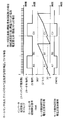
- FIG. 3 shows the phase and cycle of the sine wave voltage applied to the motor winding in correcting only one rising edge of the output signal (magnetic pole detection signal Hdet) of the Hall sensor 6 of the brushless motor control device 13 in the embodiment.
- FIG. FIG. 3 shows a state in which the brushless motor 5 is rotating at a constant speed as in FIG. 2 and the ON and OFF times of the magnetic pole detection signal Hdet are not the same.
- the phase graph of the sinusoidal waveform of the voltage applied to the motor winding is updated to a predetermined phase (30 degrees) every time the magnetic pole detection signal Hdet changes to ON (only the rising edge). Therefore, at the point A1, the phase rapidly decreases (jumps) to 30 degrees, and at the point B1, the phase does not jump but continues to increase at a predetermined speed.
- the cycle graph of the sine wave waveform the cycle is updated at both edges as in FIG. Updating the phase and the cycle in this way reduces the frequency and amount of the phase jump. Therefore, the rotational vibration and driving noise of the motor are reduced.
- the battery cooling blower is not suitable for practical use.
- FIG. 4 is a schematic diagram of the fan motor 30 according to the embodiment.
- the fan motor 30 includes a brushless motor control device 13.
- the brushless motor control device 13 determines the inverter circuit 4 that applies the driving voltage having the sine waveform to the windings of each phase of the brushless motor 5 and the rotor position of the brushless motor 5.
- a Hall sensor 6 to be detected a rotor position determination unit 12 that determines a rotor position from the timing of rising and falling edges of an output signal of the Hall sensor 6, and a rotation speed calculation that calculates a rotor rotation speed from information on the rotor position.
- a PWM waveform generator 2 that outputs a PWM signal to the inverter circuit 4 based on the rotor position and the rotor speed, and a first threshold value that is equal to or greater than a first threshold value corresponding to the minimum speed command.
- a rotation speed determination unit for determining whether the rotation speed is less than a threshold value, and a rotation speed of the brushless motor per unit time or a flow to the inverter circuit; It comprises a driving change rate determination unit 20 determines the presence or absence of driving change from the rate of change of current values, and a correction edge determination unit 10 for inputting the output signal from the rotation speed determining unit 9, and the drive change rate determination unit 20.
- the rotation speed calculation unit 11 updates the rotor rotation speed and the cycle of the sine wave waveform each time the rising edge and the falling edge of the output signal of the Hall sensor 6 are detected.
- the rotation speed judging unit 9 sets the correction timing of the phase of the sine wave waveform to only one of the rising edge and the falling edge when the rotor rotation speed is equal to or more than the first threshold value. If it is less than the first threshold, a first determination signal for both edges is output.
- the drive change rate determination unit 20 sets the correction timing of the phase of the sine wave waveform to only one edge when the change rate of the drive change is less than the second threshold value of, for example, 10%, and the change rate is equal to or more than the second threshold value. In the case of (2), a second determination signal having both edges is output.
- the correction edge determination unit 10 determines the phase of the sine wave waveform. The correction is performed at the timing of both edges, and otherwise, the phase of the sine wave waveform is corrected at the timing of one edge.
- the number of Hall sensors may be one.
- the drive change rate determination unit 20 may be the current change rate determination unit 7, and the drive change rate may be a current value change rate.
- the drive change rate determination unit 20 is the speed change rate determination unit 8, and the drive change rate may be the rotation rate change rate of the brushless motor 5.
- the drive change rate determining unit 20 determines whether the change rate of the drive change is the change rate of the current value, and the change rate of the drive change is the change rate of the rotation speed of the brushless motor 5.
- a rate determining unit 8 may be provided.
- the fan motor 30 includes the brushless motor control device 13.
- the brushless motor control device 13 of the present disclosure it is not necessary to provide an induced voltage detection circuit and a highly accurate and highly sensitive Hall sensor. In addition, it is not necessary to attach the sensor position with high accuracy. Therefore, a simple circuit configuration can be achieved. Therefore, the circuit area, component cost, and manufacturing cost can be reduced. Further, the reduction of the torque ripple reduces not only the rotation vibration and noise, the life of the bearing but also the vibration of the current during rotation of the motor. Therefore, the average current value flowing through the brushless motor 5 can be made closer to the maximum allowable value of the circuit. Therefore, it is not necessary to mount a larger circuit in order to secure a margin of the allowable current value of the circuit. For example, when the brushless motor 5 is used for a cooling fan, further reduction in size and weight can be achieved.
- the timing for updating and correcting the phase of the sine wave voltage applied to the motor winding is not limited to the rising edge as shown in FIG. For example, a falling edge may be used.
- the voltage (modulation method) applied to the motor winding is not limited to a sine wave, but may be a two-phase modulation or a three-phase modulation that results in a current waveform of the motor winding having a sine wave shape.
- the frequency and width of discontinuous large changes (jumps) of the phase of the drive voltage applied during rotation of the brushless motor 5 at the rising edge or the falling edge of the Hall sensor 6 are reduced. Therefore, the current waveform of the brushless motor 5 has a more beautiful sine wave shape, and the torque ripple is reduced.
- the brushless motor control device of the present disclosure can reduce torque ripple and reduce vibration with a simple configuration. Therefore, it is particularly suitable for controlling a cooling fan or blower motor that requires high efficiency and low noise.
- the present invention can be applied to a home or industrial brushless motor.
Abstract
ブラシレスモータの各相の巻き線に対して正弦波波形の駆動電圧を印加するインバータ回路と、ブラシレスモータのロータ位置を検出するホールセンサと、ホールセンサの出力信号の立上りおよび立下りのエッジのタイミングから、ロータ位置を判定するロータ位置判定部と、ロータ位置の情報からロータ回転速度を算出する回転速度算出部と、ロータ位置とロータ回転速度に基づき、インバータ回路へのPWM信号を出力するPWM波形生成部と、ロータ回転速度が第1の閾値以上か、第1の閾値未満かを判定する回転速度判定部と、単位時間当たりのブラシレスモータの回転速度もしくはインバータ回路に流れる電流値の変化率からの駆動変化の有無を判定する駆動変化率判定部と、回転速度判定部および駆動変化率判定部からの出力信号を入力する補正エッジ判定部とを備える。
Description
本開示は、ブラシレスモータの回転動作時、ホールセンサ等の位置検出手段によりロータ位置を検出し、モータコイルへの励磁パターンを決定するブラシレスモータ制御装置およびそれを備えたファンモータに関する。
昨今、一般的に使われているハイブリッド自動車の電池冷却用ファンには、その寿命、省エネルギー化および静音性の要求からブラシレスモータが使用されている。電池冷却用ファンには、その時々の気温または冷却対象の温度に応じたファンに必要とされる風量、または、周辺付近に発する駆動音が定められている。それらを満足するよう電池冷却用ファンを制御する必要がある。風量のバラツキは、インペラー(羽根車)に取り付けられているモータの回転速度のバラツキに依存し、駆動音またはモータ振動はモータの回転トルクに依存することが知られている。
ところで、パルス幅変調(Pulse Width Modulation、以下、適宜、「PWM」と記す)駆動で制御される三相ブラシレスモータの場合、モータ制御装置で次のように制御される。モータ制御装置は、ホールセンサの出力レベルの立上りエッジおよび立下りエッジから、ロータの回転位置を検出する。また、ホールセンサの配置または数に従い各エッジ間の回転角度は既知であり、各エッジ間の時間間隔から実回転速度を算出する。モータ制御装置は、算出された実回転速度に従い、PWM駆動を実現するインバータ回路内に備え付けられたMOSFET(Metal Oxide Semiconductor Field Effect Transisitor)素子のスイッチングパルス幅を制御する。
そのため、ホールセンサの取付け位置、またはロータマグネットのN極S極の着磁バラツキなどがあると、ロータの所定回転位置において、ホールセンサの出力レベルが切替わらず、立上りまたは立下りエッジのタイミングがズレてしまう。これにより、インバータ回路からモータコイルへの位相または周期などがズレてしまい、モータのトルクリップルが増大する。したがって、振動または騒音も大きくなってしまうことが知られている。
上記のようなバラツキへの対策として、誘起電圧を検出し、各ホールセンサの相対的な位置ズレを補正する技術が知られている(例えば、特許文献1を参照)。
しかしながら、特許文献1に開示された技術では、通常回転時に不必要な部品、例えば、モータコイルの中性点と誘起電圧を比較するコンパレータ、または、コンパレータとホールセンサ出力との排他的論理和を出力するEX-OR(exclusive or)回路(排他的論理和回路)が必要である。よって、部品点数が増加する。したがって、モータ制御装置が大型化し、コストアップとなってしまう。
特許文献2に開示された技術では、ロータ回転速度がある閾値以上の場合、または、目標速度との乖離量が閾値以下の場合、ホールセンサの片側エッジのみを用いて、モータの巻き線に対する励磁パターンを決定する。これにより、モータの回転振動とトルクリップルを低減している。しかし、急激な負荷変動時、特にロータ・イナーシャが小さい場合は、容易に脱調してしまう。
特許文献3に開示された技術では、低速回転時または起動時の不安定な状態では、3つのホールセンサを使用した位置検出の駆動をし、高速回転時で安定して駆動している状態では、1つのホールセンサを使用した位置検出の駆動を行う。これにより、ホールセンサの取り付け誤差による位相誤差または高速時の安定した位相駆動を行っている。しかし、3つのホールセンサが必要となり、1ホールセンサのみを使用するものにくらべ、ホールセンサの数が多く、高コストとなる。
上記問題の解決のため、本開示に係るブラシレスモータ制御装置は、ブラシレスモータの各相の巻き線に対して正弦波波形の駆動電圧を印加するインバータ回路と、ブラシレスモータのロータ位置を検出するホールセンサと、ホールセンサの出力信号の立上りおよび立下りのエッジのタイミングから、ロータ位置を判定するロータ位置判定部と、ロータ位置の情報からロータ回転速度を算出する回転速度算出部と、ロータ位置とロータ回転速度に基づき、インバータ回路へのPWM信号を出力するPWM波形生成部と、ロータ回転速度が第1の閾値以上か、第1の閾値未満かを判定する回転速度判定部と、単位時間当たりのブラシレスモータの回転速度もしくはインバータ回路に流れる電流値の変化率から駆動変化の有無を判定する駆動変化率判定部と、回転速度判定部および駆動変化率判定部からの出力信号を入力する補正エッジ判定部と、を備える。回転速度算出部は、ロータ回転速度および正弦波波形の周期の更新をホールセンサの出力信号の立上りエッジおよび立下りエッジの両エッジの検出毎に行う。回転速度判定部は、正弦波波形の位相の補正タイミングを、ロータ回転速度が第1の閾値以上の場合は立上りエッジと立下りエッジとのうちの一方の片エッジのみとし、ロータ回転速度が第1の閾値未満の場合は、両エッジとする第1の判定信号を出力する。駆動変化率判定部は、正弦波波形の位相の補正タイミングを、駆動変化の変化率が第2の閾値未満の場合は片エッジのみとし、変化率が第2の閾値以上の場合は、両エッジとする第2の判定信号を出力する。補正エッジ判定部は、第1の判定信号と第2の判定信号のうち、少なくとも1つが正弦波波形の位相の補正のタイミングを両エッジとする信号である場合には正弦波波形の位相の補正を両エッジのタイミングで行い、それ以外の場合には正弦波波形の位相の補正を片エッジのタイミングで行う。
また、ホールセンサの数は1つであってもよい。
また、駆動変化率判定部は電流変化率判定部であって、駆動変化の変化率は電流値の変化率であってもよい。
また、駆動変化率判定部は速度変化率判定部であって、駆動変化の変化率はブラシレスモータの回転速度の変化率であってもよい。
また、駆動変化率判定部が、駆動変化の変化率が電流値の変化率である電流変化率判定部、および駆動変化の変化率がブラシレスモータの回転速度の変化率である速度変化率判定部を備えてもよい。
また、本開示に係るファンモータは、上記のブラシレスモータ制御装置を備える。
本開示のブラシレスモータ制御装置によれば、通常回転時に不必要な部品を追加することなく、また、ホールセンサを1つに削減しても、ホールセンサの反応バラツキやロータの着磁バラツキに起因した、トルクリップル、回転振動、および騒音を低減できる。加振力低減のためにイナーシャが小さいロータであっても、急激な負荷変動に対して、脱調しにくい回転動作を実現することができる。
以下、実施の形態について図面を用いて説明する。
(実施の形態)
図1は、実施の形態におけるブラシレスモータ制御装置13のブロック図である。図1では、ブラシレスモータ制御装置13は、モータ駆動用電源線+Bとグラウンド線(GND線)を通して、12Vバッテリーから電力供給を受ける。ブラシレスモータ制御装置13は、速度指令SPreqを入力とし、ブラシレスモータ制御装置13の外部に接続されたブラシレスモータ5の回転を制御する。ブラシレスモータ制御装置13は、速度制御部1とPWM波形生成部2とインバータ回路4と電流検出部3とホールセンサ6とロータ位置判定部12と回転速度算出部11と回転速度判定部9と速度変化率判定部8と電流変化率判定部7と補正エッジ判定部10を備える。電流検出部3は、インバータに流れる電流を検出する。ホールセンサ6は、ロータの磁極位置を検出する。
図1は、実施の形態におけるブラシレスモータ制御装置13のブロック図である。図1では、ブラシレスモータ制御装置13は、モータ駆動用電源線+Bとグラウンド線(GND線)を通して、12Vバッテリーから電力供給を受ける。ブラシレスモータ制御装置13は、速度指令SPreqを入力とし、ブラシレスモータ制御装置13の外部に接続されたブラシレスモータ5の回転を制御する。ブラシレスモータ制御装置13は、速度制御部1とPWM波形生成部2とインバータ回路4と電流検出部3とホールセンサ6とロータ位置判定部12と回転速度算出部11と回転速度判定部9と速度変化率判定部8と電流変化率判定部7と補正エッジ判定部10を備える。電流検出部3は、インバータに流れる電流を検出する。ホールセンサ6は、ロータの磁極位置を検出する。
速度制御部1は、ブラシレスモータ5の回転速度を指示するための速度指令SPreqと、回転速度算出部11からロータ実回転速度SPdetとが入力される。速度制御部1は、ロータ実回転速度SPdetを速度指令SPreqが示す速度に合わせるように算出されたPWMデューティ値Dutを出力する。
PWM波形生成部2は、速度制御部1からPWMデューティ値Dutと、回転速度算出部11からロータ実回転速度SPdetと、ロータ位置判定部12からロータ位置信号Pdetと、補正エッジ判定部10から位相補正のタイミングを指定する補正エッジ判定部10の判定信号Judgeが入力される。PWM波形生成部2は、ブラシレスモータ5の巻き線に、正弦波波形の駆動電圧を印加するため、入力信号に基づき、正弦波波形が所定の周期、位相、振幅となるよう、インバータ回路4へPWM信号Wpwmを出力する。
電流検出部3は、インバータ回路4に供給される電流を電流値Adetとして検出する。
インバータ回路4は、PWM波形生成部2からのPWM信号Wpwmに従って、スイッチング素子を駆動し、ブラシレスモータ5の各相の巻き線に対して、正弦波波形の駆動電圧Vsinを印加する。
ブラシレスモータ5は、例えば3相のブラシレスモータである。ブラシレスモータ5は、U相巻線、V相巻線およびW相巻線を有するステータと、永久磁石をロータ表面に貼付けたりロータ内部に埋め込む等の構造である磁性体を備えたロータ(図示せず)とを有する。
ホールセンサ6は、ブラシレスモータ5のロータの回転動作に伴う、正弦波状の磁界の変化に基づいて、矩形波の磁極検出信号Hdetを出力する。
ロータ位置判定部12は、ロータ位置を電気角で示すロータ位置信号Pdetを出力する。ロータ位置信号Pdetは、電気角0度から360度までを示す正弦波状の信号である。ホールセンサ6の設計上の取付け位置から、磁極検出信号Hdetの立上りエッジ時および立下りエッジ時の、ロータ位置信号Pdetの値は、電気角180度の差を持って、あらかじめ定められている。例えば、立上り時は30度、立下り時は210度である。
回転速度算出部11は、磁極検出信号Hdetの立上りエッジ時および立下りエッジ時のロータ位置信号Pdetの時間間隔に基づいてロータの回転速度を算出し、ロータ実回転速度SPdetとして出力する。ロータ実回転速度SPdetは、磁極検出信号Hdetのエッジが発生する毎に(信号レベルが変化する毎に)更新される。
回転速度判定部9と速度変化率判定部8と電流変化率判定部7は、それぞれの入力に基づいて判定(選択)された、ブラシレスモータ5の巻き線に印加される正弦波電圧Vsinの位相を補正するタイミング(具体的には、片エッジまたは両エッジ)を示す回転速度の判定信号Esp、速度変化率の判定信号Esc、電流変化率の判定信号Eacをそれぞれ出力する。
回転速度判定部9と速度変化率判定部8は、回転速度算出部11からロータ実回転速度SPdetが入力される。
回転速度判定部9は、入力されたロータ実回転速度SPdetが、あらかじめ定めた閾値(最低速度指令)未満であれば、位相補正のタイミングを両エッジとする判定信号Espを出力し、閾値(最低速度指令)以上であれば、位相補正のタイミングを片エッジのみとする判定信号Espを出力する。
速度変化率判定部8は、入力されたロータ実回転速度SPdetに関して、その前回値からの変化率が、あらかじめ定めた閾値(例えば10%)以上であれば、位相補正のタイミングを両エッジとする判定信号Escを出力し、閾値(例えば10%)未満であれば、位相補正のタイミングを片エッジのみとする判定信号Escを出力する。
電流変化率判定部7は、電流検出部3からインバータ回路に流れる電流値Adetが入力される。
電流変化率判定部7は、入力された電流値Adetに関して、その前回値からの変化率が、あらかじめ定めた閾値(例えば10%)以上であれば、位相補正のタイミングを両エッジとする判定信号Eacを出力し、閾値(例えば10%)未満であれば、位相補正のタイミングを片エッジのみとする判定信号Eacを出力する。
回転速度判定部9は、ある瞬時での回転速度を判定するものである。それに対して、電流変化率判定部7および速度変化率判定部8は、ある時間間隔でのモータの挙動を測るものである。電流変化率判定部7はブラシレスモータ5の出力トルクの変化、速度変化率判定部8は、速度の変化つまりブラシレスモータ5の加速度等を測ることができる。
電流変化率判定部7および速度変化率判定部8は、ブラシレスモータ5の駆動変化率を測定することができる。ここで、駆動変化率とは、一定速度かつ一定トルクで回転している状態から、速度またはトルクが変化した比率のことを指す。電流変化率判定部7および速度変化率判定部8で構成される駆動変化率判定部20は、定常回転であるか定常回転でないかの判定、言い換えると、急激な負荷変動、急加速、および減速等の速度変更などの駆動変化の有無の判定をすることができる。ここで、駆動変化とは、一定速度かつ一定トルクで回転している状態から、速度またはトルクが変化したことを指す。
補正エッジ判定部10には、回転速度判定部9および速度変化率判定部8および電流変化率判定部7のそれぞれから、片エッジまたは両エッジのどちらのエッジで位相補正するかを判定するための判定信号である判定信号Esp、判定信号Esc、判定信号Eacが入力される。
補正エッジ判定部10は、入力された判定信号Esp,Esc,Eacのすべての入力判定信号が、位相補正のタイミングを片エッジとする判定信号である場合は、位相補正のタイミングを片エッジとする判定信号Judgeを出力し、位相補正のタイミングを両エッジとする入力判定信号が1つでもある場合は、位相補正のタイミングを両エッジのみとする判定信号Judgeを出力する。
なお、本実施の形態では、判定信号Esp、判定信号Esc、判定信号Eacの3つの判定信号により、両エッジとするか片エッジとするかを判定している。しかし、いずれか2つの判定部を用いて判定しても構わない。
PWM波形生成部2は、ブラシレスモータ5の巻き線に印加する正弦波波形の駆動電圧を、正弦波の周期はロータ実回転速度SPdetに従い、正弦波の位相はロータ位置信号Pdetに従い、正弦波の振幅はPWMデューティ値Dutに従い、更新する。正弦波の振幅はあらかじめ定めた一定時間間隔(例えば1ms間隔)で更新する。正弦波の周期は、ホールセンサ6の磁極検出信号Hdetの出力レベルが変化したタイミングで(立上りおよび立下りの両エッジで)更新する。正弦波の位相は、回転動作中、設定された周期に従い、増加もしくは減少していくが、磁極検出信号Hdetの出力レベルが変化したタイミングで、補正エッジ判定部10からの補正エッジの判定信号Judgeに従い、磁極検出信号Hdetの立上りおよび立下りの両エッジ、または、いずれかの片エッジのタイミングで、ロータ位置判定部12からのロータ位置信号Pdetに従い更新する。
上述の制御をモータ制御マイクロコントローラのソフトウェアで実現する事で、一般的なブラシレスモータが備えている制御回路に対して、新規回路の追加の必要がなく、回路規模の増大を抑制することができる。
図2は、実施の形態におけるブラシレスモータ制御装置13のホールセンサ6の出力信号(磁極検出信号Hdet)の立上りおよび立下りの両エッジの補正において、モータ巻き線に印加する正弦波電圧の位相および周期を示すタイミングチャートである。
インバータの電流検出タイミングは、インバータに備えられたMOSFETのスイッチング動作と同じ周波数であり、ブラシレスモータ5を通常使用する速度領域では、ホールセンサ6の磁極検出信号Hdetの周波数よりも、はるかに高い。
ブラシレスモータ5が一定速で回転動作している際、磁極検出信号Hdetは、理想的にはON時間とOFF時間が同一である。しかし、実際には、ロータマグネットのN極とS極の着磁バラツキ、または、ホールセンサ6に内蔵されたコンパレータのヒステリシス等のバラツキにより、ON時間とOFF時間は同一になっていない。その様子を図2に示している。
ブラシレスモータ5が一定速で回転動作している際、モータ巻き線の印加電圧の正弦波波形の位相グラフは、0から360度へ斜め上に直線となる。磁極検出信号Hdetの出力レベルが切替わる毎に(両エッジで)、所定の位相(30または210度)へ更新される。そのため、磁極検出信号HdetのONおよびOFF時間が同一になっていない場合、図2のように、ポイントA1では、位相が一気に30度へ減少(ジャンプ)し、ポイントB1では、位相が一気に210度へ増加(ジャンプ)している。
ブラシレスモータ5が一定速で回転動作している際、正弦波波形の周期グラフは、一定の値で水平に横一直線となる。磁極検出信号Hdetの出力レベルが切替わる毎に(両エッジで)、直前の両エッジ間の時間から、ロータの回転速度を算出し、正弦波波形の周期へ更新する。そのため、ポイントB2では、直前のエッジ間(ポイントA0からB0の時間)が短いため、回転速度が高く算出され、正弦波波形の周期は大きい値に更新されている。反対に、ポイントC2では、直前のエッジ間(ポイントB0からC0の時間)が長いため、回転速度が低く算出され、正弦波波形の周期は小さい値に更新されている。このように位相と周期を更新する事で、ロータの加速減速時、脱調しないように、また、ロータが最も効率よく回転するように図られている。
図3は、実施の形態におけるブラシレスモータ制御装置13のホールセンサ6の出力信号(磁極検出信号Hdet)の立上りエッジの片エッジのみの補正において、モータ巻き線に印加する正弦波電圧の位相および周期を示すタイミングチャートである。図3は、図2と同様にブラシレスモータ5が一定速で回転しており、磁極検出信号Hdetは、ONとOFFの時間が同一になっていない様子を図示している。
モータ巻き線の印加電圧の正弦波波形の位相グラフは、磁極検出信号HdetがONに変化する毎に(立上りエッジのみ)、所定の位相(30度)へ更新される。そのため、ポイントA1では、位相が一気に30度へ減少(ジャンプ)しており、ポイントB1では、位相はジャンプせず、所定の速度で増加し続けている。正弦波波形の周期グラフは、図2と同様に、周期が両エッジで更新される。このように位相と周期を更新することで、位相がジャンプする頻度や量が小さくなる。よって、モータの回転振動、駆動音が小さくなる。
ここで、周期についても両エッジではなく立上りエッジのみで更新すれば、更にモータの回転振動や駆動音が小さくなる。しかし、ブラシレスモータ5の負荷やバッテリー電圧の変動などで脱調しやすくなる。したがって、電池冷却ブロアでは実用に適さない。
図4は、実施の形態におけるファンモータ30の模式図である。ファンモータ30は、ブラシレスモータ制御装置13を備える。
以上のように、本実施の形態のブラシレスモータ制御装置13は、ブラシレスモータ5の各相の巻き線に対して正弦波波形の駆動電圧を印加するインバータ回路4と、ブラシレスモータ5のロータ位置を検出するホールセンサ6と、ホールセンサ6の出力信号の立上りおよび立下りのエッジのタイミングから、ロータ位置を判定するロータ位置判定部12と、ロータ位置の情報からロータ回転速度を算出する回転速度算出部11と、ロータ位置とロータ回転速度に基づき、インバータ回路4へのPWM信号を出力するPWM波形生成部2と、ロータ回転速度が最低速度指令に相当する第1の閾値以上か、第1の閾値未満かを判定する回転速度判定部9と、単位時間当たりのブラシレスモータ5の回転速度もしくはインバータ回路4に流れる電流値の変化率からの駆動変化の有無を判定する駆動変化率判定部20と、回転速度判定部9および駆動変化率判定部20からの出力信号を入力する補正エッジ判定部10とを備える。回転速度算出部11は、ロータ回転速度および正弦波波形の周期の更新をホールセンサ6の出力信号の立上りエッジおよび立下りエッジの両エッジの検出毎に行う。回転速度判定部9は、正弦波波形の位相の補正タイミングを、ロータ回転速度が第1の閾値以上の場合は立上りエッジと立下りエッジとのうちの一方の片エッジのみとし、ロータ回転速度が第1の閾値未満の場合は、両エッジとする第1の判定信号を出力する。駆動変化率判定部20は、正弦波波形の位相の補正タイミングを、駆動変化の変化率が例えば10%である第2の閾値未満の場合は片エッジのみとし、変化率が第2の閾値以上の場合は、両エッジとする第2の判定信号を出力する。補正エッジ判定部10は、第1の判定信号と第2の判定信号のうち、少なくとも1つが正弦波波形の位相の補正のタイミングを両エッジとする信号である場合には正弦波波形の位相の補正を両エッジのタイミングで行い、それ以外の場合には正弦波波形の位相の補正を片エッジのタイミングで行う。
これにより、通常回転時に不必要な部品を追加することなく、ホールセンサ6の反応バラツキやロータの着磁バラツキに起因した、トルクリップル、回転振動、および騒音を低減できる。加振力低減のためにイナーシャが小さいロータであっても、急激な負荷変動に対して、脱調しにくい回転動作を実現することができる。
また、ホールセンサの数は1つであってもよい。
また、駆動変化率判定部20は電流変化率判定部7であって、駆動変化の変化率は電流値の変化率であってもよい。
また、駆動変化率判定部20は速度変化率判定部8であって、駆動変化の変化率はブラシレスモータ5の回転速度の変化率であってもよい。
また、駆動変化率判定部20が、駆動変化の変化率が電流値の変化率である電流変化率判定部7、および駆動変化の変化率がブラシレスモータ5の回転速度の変化率である速度変化率判定部8を備えてもよい。
また、ファンモータ30は、ブラシレスモータ制御装置13を備える。
本開示におけるブラシレスモータ制御装置13によれば、誘起電圧検出回路、および、高精度・高感度なホールセンサを備える必要がなくなる。併せて、センサ位置の高精度な取付けも必要なくなる。このため、簡易な回路構成にすることができる。よって、回路面積、部品コストおよび製造コストを抑制することができる。また、トルクリップル低減による、回転振動および騒音の低下、軸受けの長寿命化だけでなく、モータ回転中の電流の振動が小さくなる。そのため、ブラシレスモータ5に流れる平均電流値を回路の許容可能な最大値へ、より近づけることができる。よって、回路の電流許容値の余裕を確保するために、より大型な回路を搭載する必要がなくなる。例えば、ブラシレスモータ5が冷却ファンに用いられる場合、更なる小型化および軽量化を図ることができる。
なお、モータ巻き線に印加する正弦波電圧の位相に関して、更新補正するタイミングは、図3のように立ち上がりエッジのみに限らない。例えば、立下りエッジでも良い。また、モータ巻き線に印加する電圧(変調方式)は、正弦波に限らず、結果として、モータ巻き線の電流波形が正弦波形状になる、2相変調や3相変調でも良い。
本開示によれば、ブラシレスモータ5の回転中に印加される駆動電圧の位相が、ホールセンサ6の立上りエッジまたは立下りエッジで、不連続に大きく変化(ジャンプ)する頻度および幅が減少する。そのため、ブラシレスモータ5の電流波形が、より綺麗な正弦波形状となり、トルクリップルが低減する。
ファンモータで使用されるブラシレスモータでは、ホールセンサが1つの場合に、一時的な逆回転起動などの起動失敗が起こり得る。しかし、その後ファンモータは風力を発する正回転に移行するので、特に問題はない。
本開示のブラシレスモータ制御装置は、簡単な構成でトルクリップルを低減し、振動を小さくすることが可能となる。このため、特に高効率、低騒音が要求される冷却ファンまたはブロア用モータの制御に好適である。その他、家庭用あるいは産業用のブラシレスモータにも適用可能である。
1 速度制御部
2 PWM波形生成部
3 電流検出部
4 インバータ回路
5 ブラシレスモータ
6 ホールセンサ
7 電流変化率判定部
8 速度変化率判定部
9 回転速度判定部
10 補正エッジ判定部
11 回転速度算出部
12 ロータ位置判定部
13 ブラシレスモータ制御装置
20 駆動変化率判定部
30 ファンモータ
SPreq 速度指令
Adet 電流値(電流検出値)
Dut PWMデューティ値(正弦波波形の振幅)
Wpwm PWM信号
Hdet 磁極検出信号
Pdet ロータ位置信号
SPdet ロータ実回転速度
Eac 判定信号(電流変化率判定部の判定信号)
Esc 判定信号(速度変化率判定部の判定信号)
Esp 判定信号(回転速度判定部の判定信号)
Judge 判定信号(補正エッジ判定部の判定信号)
Claims (6)
- ブラシレスモータの各相の巻き線に対して正弦波波形の駆動電圧を印加するインバータ回路と、
前記ブラシレスモータのロータ位置を検出するホールセンサと、
前記ホールセンサの出力信号の立上りおよび立下りのエッジのタイミングから、ロータ位置を判定するロータ位置判定部と、
前記ロータ位置の情報からロータ回転速度を算出する回転速度算出部と、
前記ロータ位置と前記ロータ回転速度に基づき、前記インバータ回路へのPWM信号を出力するPWM波形生成部と、
前記ロータ回転速度が第1の閾値以上か、前記第1の閾値未満かを判定する回転速度判定部と、
単位時間当たりの前記ブラシレスモータの回転速度もしくは前記インバータ回路に流れる電流値の変化率から駆動変化の有無を判定する駆動変化率判定部と、
前記回転速度判定部および前記駆動変化率判定部からの出力信号を入力する補正エッジ判定部と、
を備え、
前記回転速度算出部は、前記ロータ回転速度および前記正弦波波形の周期の更新を前記ホールセンサの出力信号の立上りエッジおよび立下りエッジの両エッジの検出毎に行い、
前記回転速度判定部は、前記正弦波波形の位相の補正タイミングを、前記ロータ回転速度が前記第1の閾値以上の場合は前記立上りエッジと前記立下りエッジとのうちの一方の片エッジのみとし、前記ロータ回転速度が前記第1の閾値未満の場合は、前記両エッジとする第1の判定信号を出力し、
前記駆動変化率判定部は、前記正弦波波形の位相の補正タイミングを、駆動変化の変化率が第2の閾値未満の場合は前記片エッジのみとし、前記変化率が前記第2の閾値以上の場合は、前記両エッジとする第2の判定信号を出力し、
前記補正エッジ判定部は、前記第1の判定信号と前記第2の判定信号のうち、少なくとも1つが前記正弦波波形の位相の補正のタイミングを前記両エッジとする信号である場合には前記正弦波波形の位相の補正を前記両エッジのタイミングで行い、
それ以外の場合には前記正弦波波形の位相の補正を前記片エッジのタイミングで行う、ブラシレスモータ制御装置。 - 前記ホールセンサの数は1つである、請求項1に記載のブラシレスモータ制御装置。
- 前記駆動変化率判定部は電流変化率判定部であって、前記駆動変化の変化率は前記電流値の変化率である、請求項1に記載のブラシレスモータ制御装置。
- 前記駆動変化率判定部は速度変化率判定部であって、前記駆動変化の変化率は前記ブラシレスモータの回転速度の変化率である、請求項1に記載のブラシレスモータ制御装置。
- 前記駆動変化率判定部が、前記駆動変化の変化率が前記電流値の変化率である電流変化率判定部、および前記駆動変化の変化率が前記ブラシレスモータの回転速度の変化率である速度変化率判定部を備えた、請求項1に記載のブラシレスモータ制御装置。
- 請求項1に記載のブラシレスモータ制御装置を備えたファンモータ。
Applications Claiming Priority (2)
| Application Number | Priority Date | Filing Date | Title |
|---|---|---|---|
| JP2018-141191 | 2018-07-27 | ||
| JP2018141191 | 2018-07-27 |
Publications (1)
| Publication Number | Publication Date |
|---|---|
| WO2020021907A1 true WO2020021907A1 (ja) | 2020-01-30 |
Family
ID=69180890
Family Applications (1)
| Application Number | Title | Priority Date | Filing Date |
|---|---|---|---|
| PCT/JP2019/023821 WO2020021907A1 (ja) | 2018-07-27 | 2019-06-17 | ブラシレスモータ制御装置およびファンモータ |
Country Status (1)
| Country | Link |
|---|---|
| WO (1) | WO2020021907A1 (ja) |
Citations (2)
| Publication number | Priority date | Publication date | Assignee | Title |
|---|---|---|---|---|
| JP2001219613A (ja) * | 2000-02-09 | 2001-08-14 | Seiko Epson Corp | モータ制御装置及び制御方法 |
| JP2013081320A (ja) * | 2011-10-05 | 2013-05-02 | Panasonic Corp | モータ駆動装置 |
-
2019
- 2019-06-17 WO PCT/JP2019/023821 patent/WO2020021907A1/ja active Application Filing
Patent Citations (2)
| Publication number | Priority date | Publication date | Assignee | Title |
|---|---|---|---|---|
| JP2001219613A (ja) * | 2000-02-09 | 2001-08-14 | Seiko Epson Corp | モータ制御装置及び制御方法 |
| JP2013081320A (ja) * | 2011-10-05 | 2013-05-02 | Panasonic Corp | モータ駆動装置 |
Similar Documents
| Publication | Publication Date | Title |
|---|---|---|
| JP5413424B2 (ja) | モータ駆動装置およびブラシレスモータ | |
| US8159162B2 (en) | Motor control apparatus, vehicle fan drive apparatus, and motor control method | |
| JP4279886B2 (ja) | 同期モータ駆動装置および方法 | |
| JP4100442B2 (ja) | モータ駆動制御装置ならびにモータの駆動制御システム | |
| JP2013046488A5 (ja) | ||
| JP4735681B2 (ja) | モータ制御回路,車両用ファン駆動装置及びモータ制御方法 | |
| JP5144337B2 (ja) | ブラシレスモータ制御装置及びブラシレスモータ | |
| JP4513914B2 (ja) | モータ制御回路,車両用ファン駆動装置及びモータ制御方法 | |
| JP2019103382A (ja) | モーター制御方法 | |
| JP4578142B2 (ja) | ブラシレスdcモータの駆動装置 | |
| CN109983688B (zh) | 无刷电动机控制装置以及无刷电动机控制方法 | |
| JP2010119220A (ja) | モータ駆動制御装置 | |
| US10944351B2 (en) | Motor drive control device and motor drive control method | |
| JP2003111469A (ja) | モータの制御方法および制御装置 | |
| JP4791319B2 (ja) | インバータ装置、圧縮機駆動装置および冷凍・空調装置 | |
| JP2013081320A (ja) | モータ駆動装置 | |
| KR20120086255A (ko) | 모터 시스템 및 모터 제어 회로 | |
| WO2020021907A1 (ja) | ブラシレスモータ制御装置およびファンモータ | |
| JP7290434B2 (ja) | モータ駆動制御装置及びモータの駆動制御方法 | |
| JP2009011014A (ja) | インバータ制御装置と電動圧縮機および家庭用電気機器 | |
| JP2007244171A (ja) | 電動機駆動装置及びそれを用いた空気調和機 | |
| JP2016136820A (ja) | モータ駆動装置 | |
| JP2008125205A (ja) | 電動機駆動装置及びそれを用いた空気調和機 | |
| JP2018174670A (ja) | モータ制御装置 | |
| JP2011055586A (ja) | モータ駆動制御回路 |
Legal Events
| Date | Code | Title | Description |
|---|---|---|---|
| 121 | Ep: the epo has been informed by wipo that ep was designated in this application |
Ref document number: 19841674 Country of ref document: EP Kind code of ref document: A1 |
|
| NENP | Non-entry into the national phase |
Ref country code: DE |
|
| 122 | Ep: pct application non-entry in european phase |
Ref document number: 19841674 Country of ref document: EP Kind code of ref document: A1 |
|
| NENP | Non-entry into the national phase |
Ref country code: JP |