WO2020021868A1 - 投影装置とその制御方法及び制御プログラム - Google Patents
投影装置とその制御方法及び制御プログラム Download PDFInfo
- Publication number
- WO2020021868A1 WO2020021868A1 PCT/JP2019/022199 JP2019022199W WO2020021868A1 WO 2020021868 A1 WO2020021868 A1 WO 2020021868A1 JP 2019022199 W JP2019022199 W JP 2019022199W WO 2020021868 A1 WO2020021868 A1 WO 2020021868A1
- Authority
- WO
- WIPO (PCT)
- Prior art keywords
- test light
- image
- area
- projection
- projected
- Prior art date
- Legal status (The legal status is an assumption and is not a legal conclusion. Google has not performed a legal analysis and makes no representation as to the accuracy of the status listed.)
- Ceased
Links
Images





Classifications
-
- G—PHYSICS
- G03—PHOTOGRAPHY; CINEMATOGRAPHY; ANALOGOUS TECHNIQUES USING WAVES OTHER THAN OPTICAL WAVES; ELECTROGRAPHY; HOLOGRAPHY
- G03B—APPARATUS OR ARRANGEMENTS FOR TAKING PHOTOGRAPHS OR FOR PROJECTING OR VIEWING THEM; APPARATUS OR ARRANGEMENTS EMPLOYING ANALOGOUS TECHNIQUES USING WAVES OTHER THAN OPTICAL WAVES; ACCESSORIES THEREFOR
- G03B21/00—Projectors or projection-type viewers; Accessories therefor
-
- H—ELECTRICITY
- H04—ELECTRIC COMMUNICATION TECHNIQUE
- H04N—PICTORIAL COMMUNICATION, e.g. TELEVISION
- H04N5/00—Details of television systems
- H04N5/74—Projection arrangements for image reproduction, e.g. using eidophor
-
- H—ELECTRICITY
- H04—ELECTRIC COMMUNICATION TECHNIQUE
- H04N—PICTORIAL COMMUNICATION, e.g. TELEVISION
- H04N9/00—Details of colour television systems
- H04N9/12—Picture reproducers
- H04N9/31—Projection devices for colour picture display, e.g. using electronic spatial light modulators [ESLM]
Definitions
- the present invention relates to a projection device, a control method thereof, and a control program.
- Patent Literature 1 discloses a half mirror that transmits light from a projection unit and guides the light to a screen, and guides light from the screen to an imaging unit, a lens disposed between the half mirror and the projection unit, A projector having the half mirror and a lens disposed between the imaging unit is described.
- Patent Document 2 describes a system including a projector and a camera that captures a projection surface onto which light is projected from the projector from the back side.
- a projection area of light from a projector is divided, projection and imaging are performed for each divided area, and flare is detected and corrected from an image obtained by the imaging.
- Patent Document 3 describes a projector that includes a projection unit and a color image sensor that captures a projection surface on which light is projected from the projection unit in the same housing.
- a captured image obtained by capturing an image of a projection surface by a color image sensor is divided into a plurality of regions, and based on an image of each region, the color of the projection surface corresponding to the region should be detected and projected. Color correction of images has been performed.
- Patent Literature 3 when a projection image is corrected in accordance with the state of a projection plane, in order to detect the state of the projection plane, a reference image is projected on the projection plane. It is necessary to take an image of the projection plane.
- a system described in Patent Document 1 in which imaging and projection are performed using a common optical system in a state where an image is projected on a projection surface, strong light from a light source passes through the optical system. It is in a state to pass. If the projection plane is imaged in this state, strong light for projection is mixed into the image sensor, and ghosts may occur in the captured image. If a ghost occurs in the captured image, the state of the projection plane cannot be recognized with high accuracy, and the correction of the projection image cannot be performed with high accuracy.
- Patent Literature 2 and the projector described in Patent Literature 3 do not perform imaging and projection by a common optical system, and do not recognize the above-described problem.
- the present invention has been made in view of the above circumstances, and has as its object to provide a projection apparatus capable of correcting a projection image according to a projection plane, a control method thereof, and a control program.
- a projection apparatus includes an optical system that projects light from a display unit onto a projection target, an image sensor that captures an image of a projection range of light by the optical system through the optical system, and a plurality of light sources set in the projection range. Sequentially select each of the areas, for the selected area, a test light projection control unit for projecting a predetermined test light from the optical system, and in a state where the test light is projected, A test light image acquisition unit that acquires a test light image, which is a captured image of the area where the test light is projected, from the imaging device; and the test target based on a characteristic difference between the test light image and the test light.
- a correction data generation unit that generates correction data for performing at least one of the color or luminance correction of an image to be projected on an object, and inputting the image data corrected based on the correction data to the display unit,
- An image projection control unit for projecting an image based on the image data, and comprising a.
- a method of controlling a projection device is directed to a projection device including: an optical system configured to project light from a display unit onto a projection target; and an imaging element configured to capture a projection range of light by the optical system through the optical system.
- a correction data generation step of generating correction data for performing at least one of a color and a luminance of an image to be projected on the projection target based on the characteristic difference from the test light; The image data corrected on the basis of the serial correction data input to the display unit, and an image projection control step of projecting an image based on the image data, and comprising a.
- a control program for a projection device includes an optical system that projects light from a display unit onto a projection target, and an imaging device that captures a projection range of light by the optical system through the optical system.
- a control program for sequentially selecting each of a plurality of regions set in the projection range, and projecting a predetermined test light from the optical system onto the selected region; And, in the state where the test light is projected, a test light image acquisition step of acquiring from the image sensor a test light image that is a captured image of the area where the test light is projected, and the test light image, Correction data generation for generating correction data for correcting at least one of color and luminance of an image to be projected on the projection target based on a characteristic difference from the test light And step, the image data corrected based on the correction data inputted to the display section, is intended for executing an image projection control step of projecting an image based on the image data, to the computer.
- a projection device capable of correcting a projection image according to a projection plane, a control method thereof, and a control program.
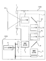
- FIG. 1 is a schematic diagram illustrating an external configuration of a projector 100 that is an embodiment of a projection device of the present invention.
- FIG. 2 is a schematic diagram showing an internal configuration of the projector 100 shown in FIG.
- FIG. 3 is a schematic diagram illustrating a configuration example of a display unit 1 illustrated in FIG. 2.
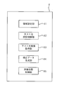
- FIG. 4 is a functional block diagram of a system control unit 8 shown in FIG. It is a schematic diagram which shows an example of the screen SC.
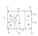
- FIG. 6 is a schematic diagram showing a captured image IG for setting an area, which is obtained by capturing an image of a projection range AR on the screen SC shown in FIG.
- FIG. 14 is a diagram illustrating a modification of a region for which correction data is to be generated.
- FIG. 1 is a schematic diagram illustrating an external configuration of a projector 100 that is an embodiment of a projection device of the present invention.
- FIG. 2 is a schematic diagram showing an internal configuration of the projector 100 shown in FIG.
- FIG. 3
- FIG. 7 is a diagram illustrating a state in which image data IM1 before correction by an image projection control unit 85 is projected on a projection range AR.
- FIG. 11 is a diagram illustrating a state in which image data IM2 after image data IM1 is corrected by an image projection control unit 85 is projected onto a projection range AR.
- 3 is a flowchart for describing correction data generation processing by the projector 100 shown in FIG. 9 is a flowchart for describing a first modification of the correction data generation processing by the projector 100 shown in FIG. It is a schematic diagram which shows an example of the screen SC.
- FIG. 13 is a schematic diagram illustrating a captured image IG for setting an area, which is obtained by capturing an image of the projection range AR on the screen SC illustrated in FIG.
- FIG. 1 is a schematic diagram showing an external configuration of a projector 100 which is an embodiment of the projection device of the present invention.
- the projector 100 includes a main body 100A and an optical unit 100B supported by the main body 100A.
- the optical unit 100B may be configured to be detachable from the main body 100A.
- FIG. 2 is a schematic diagram showing the internal configuration of the projector 100 shown in FIG.
- FIG. 3 is a schematic diagram showing a configuration example of the display unit 1 shown in FIG.
- the projector 100 is configured to project an image on a screen SC as a projection target and to be able to capture at least a projection range in which an image on the screen SC is projected.
- the projector 100 includes a display unit 1, a projection optical system 2, a common optical system 3 constituting an optical system, an optical member 4, an imaging optical system 5, an imaging element 6, and illumination.
- the device includes a device 7 and a system control unit 8.
- the display unit 1 and the system control unit 8 are housed in the main unit 100A.
- the projection optical system 2, the common optical system 3, the optical member 4, the imaging optical system 5, and the imaging device 6 are housed in the optical unit 100B.
- the display unit 1 displays an image for projection based on input image data. As shown in FIG. 3, the display unit 1 includes a light source unit 40 and a light modulation element 44.
- the light source unit 40 includes a light source 41 that emits white light, a color wheel 42, and an illumination optical system 43.
- the light source 41 is configured to include a light emitting element such as a laser or an LED (Light Emitting Diode).
- the color wheel 42 is disposed between the light source 41 and the illumination optical system 43.
- the color wheel 42 is a disk-shaped member, and is provided along its circumferential direction with an R filter that transmits red light, a G filter that transmits green light, and a B filter that transmits blue light.
- the color wheel 42 is rotated around an axis, and splits white light emitted from the light source 41 into red light, green light, and blue light in a time division manner and guides the white light to the illumination optical system 43.
- Light emitted from the illumination optical system 43 enters the light modulation element 44.
- the light modulation element 44 spatially modulates the light emitted from the illumination optical system 43 based on image data, and emits the spatially modulated light to the projection optical system 2.
- the display unit 1 shown in FIG. 3 is an example in which a DMD (Digital Micromirror Device) is used as the light modulation element 44, and the light modulation element 44 is, for example, LCOS (Liquid Crystal On Silicon), MEMS (Micro Electro Mechanical). (Systems) element or a liquid crystal display element or the like can be used.
- a DMD Digital Micromirror Device
- the light modulation element 44 is, for example, LCOS (Liquid Crystal On Silicon), MEMS (Micro Electro Mechanical). (Systems) element or a liquid crystal display element or the like can be used.
- the display unit 1 may display an image using a self-luminous organic EL (electro-luminescence) display element, and cause the displayed image to enter the projection optical system 2. Further, a device that displays an image by scanning with a laser beam may be used.
- a self-luminous organic EL electro-luminescence
- the projection optical system 2 receives the light from the display unit 1 and includes, for example, a relay optical system including at least one lens.
- the light that has passed through the projection optical system 2 enters the optical member 4, is reflected by the optical member 4, and enters the common optical system 3.
- the common optical system 3 projects the light passing through the projection optical system 2 onto the screen SC and forms an image of a subject on the screen SC, and is configured by, for example, a relay optical system.
- the common optical system 3 includes a lens group 31 including at least one lens, an optical member 32, a lens group 33 including at least one lens, a lens group 34 including at least one lens, Is provided.
- the lens group 31, the optical member 32, the lens group 33, and the lens group 34 are arranged on the optical path in this order from the screen SC side.
- the lens 31a located closest to the screen SC of the lens group 31 is exposed from the housing of the optical unit 100B as shown in FIG.
- the optical member 32 is a member for bending the optical path of the common optical system 3, and for example, a half mirror, a beam splitter, a polarizing member, or the like is used. However, it is also possible to adopt a configuration in which the optical member 32 is not used by changing the projection direction. In that case, the lens group 31 and the lens group 33 may be an integrated lens group.
- Light from the display unit 1 that has passed through the projection optical system 2 is reflected by the optical member 4 and enters the lens group 34.
- this lens group 34 an intermediate image formed by light from the display unit 1 is formed at a position PS between the lens groups 33 and 34.
- the image forming position of the intermediate image is not limited to this.
- This intermediate image passes through the lens group 33 and enters the optical member 32, is reflected by the optical member 32, and enters the lens group 31.
- the intermediate image incident on the lens group 31 is projected toward the screen SC to be a projected image.
- the range where light is projected from the common optical system 3 on the screen SC is referred to as the projection range of the screen SC.
- the subject light that has entered the lens group 31 from the screen SC side passes through the lens group 31, is reflected by the optical member 32, and enters the lens group 33.
- the lens group 33 forms an intermediate image formed by subject light at a position PS between the lens group 33 and the lens group 34.
- This intermediate image passes through the lens group 34 and enters the optical member 4, passes through the optical member 4, and enters the imaging optical system 5.
- the imaging optical system 5 is for imaging the intermediate image formed at the position PS on the imaging device 6.
- the image pickup optical system 5 is disposed in front of the image pickup device 6, condenses subject light transmitted through the optical member 4, and forms an image on the image pickup device 6.
- the imaging optical system 5 includes at least one lens.
- the imaging device 6 is, for example, a CCD (Charge Coupled Device) image sensor or a CMOS (Complementary Metal Oxide Semiconductor) image sensor.
- CCD Charge Coupled Device
- CMOS Complementary Metal Oxide Semiconductor
- the optical member 4 is constituted by, for example, a half mirror, a beam splitter, a polarizing member, or the like.
- the optical member 4 reflects the light from the display unit 1 that has passed through the projection optical system 2 and guides the light to the common optical system 3, and converts the light to the subject light imaged at the position PS by the lens group 33 of the common optical system 3.
- the intermediate image based on the image is guided to the image sensor 6 through the imaging optical system 5.
- the image sensor 6 captures the light projection range of the common optical system 3 through the common optical system 3 for projecting the light spatially modulated by the light modulator 44 onto the screen SC. I have.
- the lighting device 7 includes a plurality of light emitting elements 7a arranged in a circle around the optical axis of the lens 31a, and a driver for driving the light emitting elements 7a.
- the system control unit 8 controls the light to be incident on the projection optical system 2 from the display unit 1, controls the imaging of a subject by the imaging device 6, and controls the light emission of the illumination device 7.
- the system control unit 8 includes a processor and a storage unit. A ROM (Read Only Memory) and a RAM (Random Access Memory) are provided.
- a programmable logic device CPU (Central Processing Unit), which is a general-purpose processor for executing various processes by executing a program, or a processor capable of changing a circuit configuration after manufacturing, such as an FPGA (Field Programmable Gate Array).
- a dedicated electric circuit which is a processor having a circuit configuration specifically designed to execute a specific process such as Programmable Logic Device (PLD) or ASIC (Application Specific Integrated Circuit), is included.
- PLD Programmable Logic Device
- ASIC Application Specific Integrated Circuit
- the structure of these processors is more specifically an electric circuit combining circuit elements such as semiconductor elements.
- the processor of the system control unit 8 may be configured by one of the various processors described above, or a combination of two or more processors of the same type or different types (for example, a combination of a plurality of FPGAs or a combination of a CPU and an FPGA). Combination).
- FIG. 4 is a functional block diagram of the system control unit 8 shown in FIG.
- the processor of the system control unit 8 executes an application program including a control program of the projection device to execute a region setting unit 81, a test light projection control unit 82, a test light image acquisition unit 83, a correction data generation unit 84, and an image. It functions as the projection control unit 85.
- the area setting unit 81 causes the image sensor 6 to image the projection range without projecting light from the common optical system 3, and obtains an image IG for area setting from the image sensor 6.
- the region setting unit 81 sets a plurality of regions (hereinafter, referred to as detection regions) with respect to the projection range of the screen SC based on the captured image IG for region setting. The method of setting the plurality of detection areas will be described with reference to FIGS.
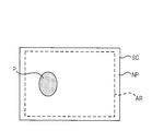
- FIG. 5 is a schematic view showing an example of the screen SC.
- the screen SC shown in FIG. 5 includes an elliptical first region P and a second region NP different in color or luminance from the first region P.
- a projection range AR of light projected from the common optical system 3 is indicated by a broken line.
- FIG. 6 is a schematic diagram illustrating a captured image IG for setting an area, which is obtained by capturing the projection range AR on the screen SC illustrated in FIG.
- the region setting unit 81 performs a process of extracting a feature amount from the captured image IG, recognizes a pattern in the projection range AR of the screen SC based on the extracted feature amount, and performs processing on the projection range AR according to the recognized pattern. To set a plurality of detection areas.
- the feature amount is the color, brightness, shape, or the like of each object included in the captured image IG.
- the region setting unit 81 recognizes that the captured image IG is composed of the first region P and the second region NP having different colors or luminances based on the extracted feature amount.
- the captured image IG corresponds to the projection range AR of the screen SC. Therefore, by the above-described recognition processing, it is recognized that the projection range AR of the screen SC has the first area P and the second area NP.
- the area setting unit 81 sets at least one detection area at a representative position in the first area P of the captured image IG (for example, at the center or end of the first area P).
- FIG. 6 shows an example in which two pixels above and below the center of the first region P are set as a detection region T6 and a detection region T7, respectively.
- the area setting unit 81 sets at least one detection area at a representative position in the second area NP of the captured image IG (for example, at the center or end of the second area NP).
- FIG. 6 shows an example in which the pixels at the four corners of the second area NP are set as detection areas T1, T3, T4, and T5, and the pixel at the center of the second area NP is set as the detection area T2. Have been.
- the captured image IG corresponds to the projection range AR. Specifically, each divided area when the projection range AR is equally divided by the total number of pixels of the captured image IG corresponds to each pixel of the captured image IG. For this reason, the plurality of detection areas (the detection areas T1 to T7 in the example of FIG. 6) set in the captured image IG in this way are used as the plurality of detection areas set in the projection range AR. Become.
- the test light projection control unit 82 shown in FIG. 4 sequentially selects each of the plurality of detection regions set in the projection range by the region setting unit 81, and sets a predetermined color for the selected detection region. Is projected from the common optical system 3 onto the screen SC.
- the test light projection control unit 82 projects the test light only on the detection area T1 in the projection range AR, and other than the detection area T1 in the projection range AR.
- the image data for the test is generated such that no light is projected on the area of the image data, and the image data for the test is input to the light modulation element 44. As a result, the test light is projected only on the detection area T1 in the projection range AR.
- the test light image acquisition unit 83 causes the image sensor 6 to image the projection range in a state where the test light is projected on the detection area in the projection range. Then, of the captured images obtained by this imaging, a test light image, which is a captured image of a portion of the detection area where the test light is projected, is acquired from the image sensor 6.
- the correction data generation unit 84 determines the color of the image to be projected on the screen SC based on the characteristic difference between the test light image acquired by the test light image acquisition unit 83 and the test light projected by the test light projection control unit 82.
- the correction data for performing the correction is generated.
- the generated correction data is stored in the ROM of the system control unit 8.
- the characteristic difference between the test light image and the test light is a difference between the color of the test light image and the color of the test light.
- the test light image acquisition unit 83 outputs a test light image GT1 that is a captured image of the detection area T1 in a state where the test light is projected onto the detection area T1, and a test light image GT2 that is a captured image of the detection area T2.
- a test light image GT2 which is a captured image of the detection area T2 in a state where the test light is projected on the test light image GT3 which is a captured image of the detection area T3 in a state where the test light is projected on the detection area T3.
- a test light image GT4 which is a captured image of the detection area T4 when the test light is projected on the detection area T4, and an imaging of the detection area T5 when the test light is projected on the detection area T5.
- test light image GT5 that is an image and a test light image GT6 that is a captured image of the detection area T6 in a state where the test light is projected on the detection area T6.
- the correction data generation unit 84 obtains, for example, a characteristic difference between each of the test light images GT6 and GT7 and the test light, and corrects the color of the image to be projected on the first area P based on these two characteristic differences. To generate first correction data.
- the first correction data is generated such that when the test light is projected on the entire first area P, the color of the captured image of the first area P on which the test light is projected matches the color of the test light. Is done.
- the correction data generation unit 84 obtains a characteristic difference between each of the test light images GT1 to GT5 and the test light, and corrects the color of the image to be projected on the second area NP based on these five characteristic differences. Correction data is generated.
- the second correction data is generated such that when the test light is projected on the entire second area NP, the color of the captured image of the second area NP onto which the test light is projected matches the color of the test light. Is done.
- the correction data generation unit 84 includes the second area NP including a divided area A1 including the detection area T1, a divided area A2 including the detection area T2, and a detection area T3. It divides into a divided region A3, a divided region A4 including the detection region T4, and a divided region A5 including the detection region T5, and further divides the first region P into a divided region A6 including the detection region T6 and a detection region. It is also possible to divide the image into the divided areas A7 including T7 and generate correction data individually for the divided areas A1 to A7.
- the correction data generation unit 84 calculates the luminance between the test light image and the test light as a characteristic difference between the test light image acquired by the test light image acquisition unit 83 and the test light projected by the test light projection control unit 82. The difference may be obtained, and correction data for correcting the luminance of the image to be projected on the screen SC may be generated based on the luminance difference.
- the correction data generation unit 84 calculates the color difference between the test light image and the test light as a characteristic difference between the test light image acquired by the test light image acquisition unit 83 and the test light projected by the test light projection control unit 82. , And a luminance difference between the test light image and the test light may be obtained, and correction data for correcting the color and luminance of the image to be projected on the screen SC may be generated based on the color difference and the luminance difference. .
- the image projection control unit 85 shown in FIG. 4 corrects the color and / or luminance of the image data to be input to the light modulation element 44 based on the correction data stored in the ROM. Then, the corrected image data is input to the light modulation element 44, and an image based on the corrected image data is projected onto the projection range AR.
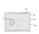
- FIG. 8 is a diagram showing a state in which image data IM1 (for example, a solid image entirely composed of a single color) before correction by the image projection control unit 85 is projected on the projection range AR.
- image data IM1 for example, a solid image entirely composed of a single color
- the color of the portion of the image data IM1 that overlaps with the first region P changes the color of the portion of the image data IM1 that overlaps with the second region NP due to the difference in color or luminance between the first region P and the second region NP. Is in a different state.
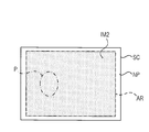
- FIG. 9 is a diagram showing a state in which image data IM2 obtained by correcting image data IM1 by image projection control unit 85 is projected onto projection range AR.
- the image projection control unit 85 corrects the portion of the image data IM1 shown in FIG. 8 which is projected on the first area P with the first correction data, and projects the portion projected on the second area NP of the image data IM1.
- the corrected portion is corrected by the second correction data to generate image data IM2.
- the corrected image data IM2 As shown in FIG. 9, by projecting the corrected image data IM2, the color of the portion overlapping the first region P and the portion overlapping the second region NP in the image data IM2 becomes the same, and the pattern of the screen SC , The image data IM2 can be visually recognized.
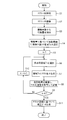
- FIG. 10 is a flowchart for describing the correction data generation processing by the projector 100 shown in FIG.
- the area setting unit 81 controls the illumination device 7 to illuminate the screen SC with white light or the like (Step S1).
- the area setting unit 81 controls the image sensor 6 to image the screen SC (Step S2).
- the region setting unit 81 extracts a feature amount from the captured image of the projection range AR captured in step S2 (step S3).
- the region setting unit 81 sets k (k is a natural number of 2 or more) detection regions Tn (n is 1 to k) for the projection range AR based on the extracted feature amount (step S4). ).
- test light projection control unit 82 sets the above “n” to 1 (step S5), selects the detection area Tn (step S6), and applies the test light only to the selected detection area Tn. Projection is performed (step S7).
- test light image acquisition unit 83 causes the image sensor 6 to capture an image of the screen SC, and acquires a test light image, which is a captured image of the test light projected on the projection range AR in Step S7, from the image sensor 6; This is stored in the RAM (step S8).
- the test light image acquisition unit 83 determines whether “n” being set is “k” (step S9), and if “n” is less than “k” (step S9: NO). After the value of "n” is increased by one in step S10, the processes in steps S6 to S8 are performed. If “n” is “k” (step S9: YES), the test light image acquisition unit 83 generates correction data based on the k test light images stored in the RAM, and stores the correction data in the ROM. It is stored (step S11).
- the test light is sequentially projected on each of the plurality of detection areas set in the projection range on the screen SC, and the sequentially projected test light is generated by the image sensor 6.
- the image is taken to obtain k test light images.
- correction data for correcting at least one of the color and the luminance of the image data to be input to the light modulation element 44 at the time of projecting the image is generated.
- the entire projection range is obtained.
- the possibility that strong light from the display unit 1 leaks into the image sensor 6 can be reduced.
- the correction data can be generated with high accuracy, and the visibility of the projected image can be improved even when the color, brightness, and the like in the projection range of the screen SC are not uniform.
- the size of the detection area set in the projection range is arbitrary as long as the size is sufficiently smaller than the projection range. However, in order to obtain the above-described effects more remarkably, it is preferable to make the size as small as possible. As described above, it is preferable that the size of each divided area when the projection range is equally divided by the total number of pixels constituting the captured image IG be the size of the detection area. Thereby, the possibility that a ghost may occur in the test light image can be reduced as much as possible.
- the setting of the detection area for the projection range is performed based on the pattern in the projection range of the screen SC. For this reason, the number of detection areas can be suppressed to a necessary minimum. Accordingly, the processing load on the system control unit 8 can be reduced and the processing speed can be improved.
- the imaging in step S2 in FIG. 10 for recognizing the pattern in the projection range of the screen SC is performed in a state where the illumination device 7 illuminates the screen SC. Therefore, the recognition accuracy of the pattern can be improved. Therefore, the number of detection areas that can be set can be effectively reduced, and the accuracy of the correction data can be increased.
- the illumination device 7 includes, as an example, a light-emitting element 7a arranged in a circle around the optical axis of the lens 31a of the common optical system 3. For this reason, the entire projection range of the screen SC can be illuminated with uniform light, and the recognition accuracy of the pattern in the projection range can be improved. However, the illumination device 7 can be realized in other arrangements as long as it can illuminate the entire projection range of the screen SC with uniform light.
- step S1 in FIG. 10 the processing in step S1 in FIG. 10 is not essential, and the lighting device 7 is not essential. Even when the captured image IG for setting the area is acquired without illuminating the screen SC, it is sufficiently possible to recognize the pattern of the screen SC if the projector 100 is placed in a somewhat bright environment. .
- the area setting unit 81 obtains a plurality of predetermined areas (for example, by dividing the projection range into a grid pattern) with respect to the projection range without recognizing a pattern in the projection range on the screen SC.
- Each divided area or an area corresponding to each pixel configuring the captured image IG) may be set as the detection area.
- the detection area As described above, by setting the detection area according to the pattern in the projection range of the screen SC, the number of detection areas to be set can be reduced, and the processing load can be reduced and high-speed processing can be performed.
- the ROM of the system control unit 8 is configured to store information of a predetermined specific region with respect to the projection range, and the region setting unit 81 avoids the specific region and sets a plurality of detection regions. It is preferable to set an area.
- the specific region is a region where a ghost due to the test light may occur in a test light image obtained by imaging the region with the image sensor 6 while projecting the test light onto the region.
- a ghost occurs in a captured image obtained by capturing the screen SC by the image sensor 6 when the test light is being projected. Hateful. However, depending on the optical path through which the test light passes, a part of the test light may leak into the image sensor 6. Therefore, a projection area of the test light where a ghost may occur when projecting such a test light is obtained in advance as the above-mentioned specific area, and the test light is projected while avoiding this specific area, thereby improving the accuracy of the correction data. Can be more enhanced.
- This specific area sequentially projects test light at each position of a projection range corresponding to each pixel constituting the captured image IG for setting an area, and determines whether a ghost has occurred in the captured image of the projected test light. By performing the inspection, it can be determined in advance.
- FIG. 11 is a flowchart illustrating a first modification of the correction data generation process performed by projector 100 shown in FIG.
- FIG. 11 illustrates an operation example in which the correction data generation unit 84 individually generates correction data for the divided areas A1 to A7 illustrated in FIG. Operations before step S5 shown in FIG. 11 are the same as those in FIG.
- the same processes as those in FIG. 10 are denoted by the same reference numerals, and description thereof will be omitted.
- step S5 If n is set to 1 in step S5, the processing of step S6, step S7, and step S8 is performed. Up to this point, it is the same as FIG.
- the correction data generation unit 84 generates correction data for correcting the color of the image projected on the divided area An including the detection area Tn based on the test light image acquired in step S8. (Step S21).
- the correction data is generated such that when the test light is projected on the entire divided area An, the color of the captured image of the divided area An on which the test light is projected matches the color of the test light.
- test light image acquisition unit 83 determines whether “n” being set is “k” (Step S22), and if “n” is less than “k” (Step S22: NO). In step S23, the value of n is increased by one (step S23), and the process proceeds to step S24. If “n” is "k” (step S22: YES), the process proceeds to step S25. .
- step S24 the system control unit 8 projects the test light corrected based on the correction data generated in step S21 onto the divided area Am (m is each value less than n), and furthermore, detects the detection area Tn.
- the image data for projecting the test light on the display unit 1 is input to the display unit 1, and an image based on the image data is projected on the projection range AR.
- n is 2 in step S23, the test light after correction is projected onto the divided area A1 and the test light is projected onto the detection area T2 in the projection area AR. State.
- step S24 the process proceeds to step S8.
- step S25 the image projection control unit 85 additionally projects the test light corrected based on the correction data generated in step S21 onto the divided area An (here, the divided area A7). As a result, the corrected test light is projected on each of all the divided areas A1 to A7.
- the projection range AR is imaged in a state where the test light is projected only on the detection area T1, and a captured image of the detection area T1 is obtained as a test light image.
- the correction data for the divided area A1 is generated based on the test light image
- the test light corrected based on the correction data is projected onto the divided area A1
- the test light is projected onto the detection area T2. Is done.
- the projection range AR is imaged in a state where the corrected test light is projected on the divided area A1 and the test light is projected on the detection area T2, and a captured image of the detection area T2 is obtained as a test light image. Is done.
- the test light corrected based on the correction data is additionally projected on the divided area A2, and the test light is projected on the detection area T3. Projected.
- the projection area AR is imaged in a state where the corrected test light is projected on the divided areas A1 and A2 and the test light is projected on the detection area T3, and the captured image of the detection area T3 is a test light image.
- the test light corrected based on the correction data is additionally projected on the divided area A3, and the test light is projected on the detection area T4. Projected.
- the projection range AR is imaged in a state where the corrected test light is projected on the divided areas A1, A2, and A3 and the test light is projected on the detection area T4, and the captured image of the detection area T4 is tested. Obtained as an optical image.
- the test light corrected based on the correction data is additionally projected on the divided area A4, and the test light is projected on the detection area T5. Projected.
- the projection range AR is imaged in a state where the corrected test light is projected on the divided areas A1, A2, A3, and A4 and the test light is projected on the detection area T5, and the captured image of the detection area T5 is taken. Is obtained as a test light image.
- the test light corrected based on the correction data is additionally projected on the divided area A5, and the test light is projected on the detection area T6. Projected.
- the projection range AR is imaged in a state where the corrected test light is projected on the divided areas A1, A2, A3, A4, and A5 and the test light is projected on the detection area T6.
- a captured image is acquired as a test light image.
- the test light corrected based on the correction data is additionally projected on the divided area A6, and the test light is projected on the detection area T7. Projected.
- the projection range AR is imaged in a state where the corrected test light is projected on the divided areas A1, A2, A3, A4, A5, and A6 and the test light is projected on the detection area T7, and the detection area is captured.
- the captured image at T7 is acquired as a test light image.
- the test light corrected based on the correction data is additionally projected on the divided area A7, and the correction processing is completed.
- the corrected white light is projected on the whole, and the pattern of the projection range AR disappears.
- an image based on the image data is corrected by the correction data, and is projected onto the projection range AR without being affected by the pattern of the projection range AR.
- the test light projection control unit 82 projects the test light on the detection area Tn, and corrects the detection area Tn different from the detection area Tn (the detection area Tn in which the correction data has been generated).
- the projection of the corrected image based on the data is performed in parallel.
- test light is sequentially projected on each of the detection areas T1 to T7 to generate correction data corresponding to each detection area, and then each detection
- the time until image display after the correction can be reduced. Therefore, for example, even when the user displays an image immediately after the activation of the projector 100, the image can be displayed at high speed without being affected by the pattern of the projection range AR.
- the detection area Tn to which the test light for projecting the test light image is to be projected is selected by selecting a position away from the projection area of the corrected test light projected simultaneously with the test light. It is possible to prevent a ghost from occurring in the captured image of the detection area Tn.
- the image projected simultaneously with the test light for acquiring the test light image is an image based on the corrected test light. However, the image projected on the image data after the correction based on the correction data of any image data input by the user is used. Based image.
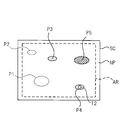
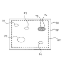
- FIG. 12 is a schematic view showing an example of the screen SC.
- the screen SC shown in FIG. 12 includes elliptical areas P1 to P5 having different colors or luminances, and areas NP having different colors or luminances from the areas P1 to P5.
- a projection range AR of light projected from the common optical system 3 is indicated by a broken line.
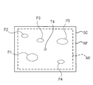
- FIG. 13 is a schematic diagram illustrating a captured image IG for setting an area, which is obtained by capturing the projection range AR on the screen SC illustrated in FIG.
- the region setting unit 81 performs a process of extracting a feature amount from the captured image IG illustrated in FIG. 13, recognizes a pattern in the projection range AR of the screen SC based on the extracted feature amount, and according to the recognized pattern. A plurality of detection areas are set for the projection range AR.
- the area setting unit 81 recognizes that the captured image IG has areas P1 to P5 and areas NP having different colors or luminances based on the extracted feature amount.
- the captured image IG corresponds to the projection range AR of the screen SC. For this reason, by the above-described recognition processing, it is recognized that the projection range AR of the screen SC has areas P1 to P5 and areas NP having different colors or luminances.
- the area setting unit 81 divides the recognized areas P1 to P5 and the area NP into groups having similar colors or luminances, and represents a representative position of any one area included in each group (for example, a representative position of the area). At least one detection area is set at the center or at the end.
- the plurality of areas having similar colors are, for example, a plurality of areas in which the chromaticity difference between each area and the other area is equal to or less than a threshold, or the chromaticity difference and the brightness difference between each area and the other area. It refers to a plurality of areas each having a threshold or less.
- the plurality of areas having similar luminance refers to a plurality of areas in which the difference in luminance between each area and the other area is equal to or smaller than a threshold.
- the difference in chromaticity between the area P1 and the area P2 is equal to or less than the threshold, and the difference in chromaticity between each of the area P1 and the area P2 and each of the areas P3, P4, P5, and NP is equal to the threshold.
- the area P1 and the area P2 are set as a group G1.
- the difference in chromaticity between the area P3 and the area P4 is equal to or smaller than the threshold value, and the difference in chromaticity between each of the area P3 and the area P4 and each of the areas P1, P2, P5, and NP exceeds the threshold value.
- Area P3 and area P4 are set as group G2.
- the area P5 Since the difference between the chromaticity of the area P5 and the chromaticities of all other areas exceeds the threshold value, the area P5 is set as a group G3. Further, since the difference between the area NP and the chromaticities of all other areas exceeds the threshold, the area NP is set as the group G4.
- the area NP is, for example, a white area, and the characteristic difference between the captured image and the test light in the projection area when the test light is projected on the area NP is equal to or smaller than a predetermined value (in other words, the area that does not require correction). ).
- the area setting unit 81 sets the detection area T1 at a representative position of the area P1 in the group G1, sets the detection area T2 at a representative position of the area P4 in the group G2,
- the detection area T3 is set at a representative position of the area P5 in the group G3, and the detection area T4 is set at a representative position of the area NP in the group G4.
- the test light projection control unit 82 selects the detection area T1, and projects the test light only on the selected detection area T1. Then, the correction data generation unit 84 uses the characteristic difference between the test light image, which is the captured image of the detection area T1 on which the test light is projected, and the test light, for the area P1 in which the detection area T1 is set. Correction data (correction data for canceling the color of the area P1) is generated and stored.
- the test light projection control unit 82 selects the detection area T2 and projects the test light only on the selected detection area T2.
- the correction data generation unit 84 uses the characteristic difference between the test light image, which is the captured image of the detection area T2 on which the test light is projected, and the test light, for the area P4 in which the detection area T2 is set. Correction data (correction data for canceling the color of the area P4) is generated and stored.
- the test light projection control unit 82 selects the detection area T3, and projects the test light only on the selected detection area T3.
- the correction data generation unit 84 performs the correction for the area P5 in which the detection area T3 is set based on the characteristic difference between the test light and the test light image, which are the captured images of the detection area T3 on which the test light is projected.
- Correction data (correction data for canceling the color of the area P5) is generated and stored.
- the test light projection control unit 82 selects the detection area T4 and projects the test light only on the selected detection area T4. Then, the correction data generator 84 determines a characteristic difference between the test light and the test light image, which are captured images of the detection area T4 on which the test light is projected. Since this characteristic difference is equal to or less than the predetermined value, generation of correction data for the area NP in which the detection area T4 is set becomes unnecessary, and this correction data is not generated.
- the test light image acquisition unit 83 is a captured image of the test light projection area in a state where the test light is projected on an area P2 other than the area P1 in the group G1 to which the area P1 including the detection area T1 belongs.
- An estimated test light image is generated based on the test light image of the detection area T1.
- the difference or ratio between the chromaticity (or lightness) of the area P1 and the area P2 can be obtained.
- the test light image of the detection area T1 is processed based on the difference or ratio of the chromaticity (or lightness) of the area P1 and the area P2 (for example, the test light image is multiplied by this ratio, and the difference is determined.
- an estimated test light image of the area P2 can be obtained.
- the test light image acquisition unit 83 is a captured image of the test light projection area in a state where the test light is projected on an area P3 other than the area P4 in the group G2 to which the area P4 including the detection area T2 belongs.
- An estimated test light image is generated based on the test light image in the detection area T2.
- the difference or ratio between the chromaticity (or lightness) of the area P3 and the area P4 can be obtained. Therefore, by processing the test light image of the detection area T2 based on the difference or ratio of the chromaticity (or lightness) of the area P1 and the area P2, an estimated test light image of the area P3 can be obtained.
- the correction data generation unit 84 generates and stores correction data for the area P2 (correction data for canceling the color of the area P2) based on the characteristic difference between the estimated test light image of the area P2 and the test light, Based on the characteristic difference between the estimated test light image of the area P3 and the test light, correction data for the area P3 (correction data for canceling the color of the area P3) is generated and stored.
- the image projection control unit 85 corrects the color of the image data to be input to the light modulation element 44 based on the correction data stored in this manner, and converts the corrected image data into light.
- the image is input to the modulation element 44 and projected on the projection range AR based on the image data after the correction.
- an image corrected to cancel the color of the area P1 based on the correction data for the area P1 is projected on the area P1 of the image projected on the projection range AR.
- An image corrected to cancel the color of the area P2 based on the correction data for the area P2 is projected on the area P2 portion of the image projected on the projection range AR.
- An image corrected to cancel the color of the area P3 based on the correction data for the area P3 is projected on the area P3 in the image projected on the projection range AR.
- An image corrected to cancel the color of the area P4 based on the correction data for the area P4 is projected on the area P4 in the image projected on the projection range AR.
- An image corrected to cancel the color of the area P5 based on the correction data for the area P5 is projected on the area P5 in the image projected on the projection range AR.
- the area setting unit 81 divides the projection range AR into groups having similar colors or luminances, and sets the detection area in one area included in each group. Even when a complicated pattern exists, the number of detection areas to be set can be reduced, and the time for generating correction data can be reduced. Further, even if the number of detection areas is reduced, the test light of the same group as the area is projected on the area where the test light is not projected (in the example of FIG. 13, the area P2 and the area P3). The test light image can be estimated using the test light image of another area. For this reason, it is possible to accurately generate correction data even in an area where the test light is not projected.
- a plurality of areas belonging to the same group are areas having a small difference in color or luminance. Therefore, for an area where the test light is not projected (in the example of FIG. 13, the area P2 and the area P3), the test light images of the other areas which are projecting the test light of the same group as the area are not changed. , An estimated test light image. Even in this case, it is possible to obtain a state in which the colors of the areas P2 and P3 have been erased to some extent during the projection of the image.
- the projection of the corrected image based on the correction data and the projection of the test light onto the detection area for generating the correction data can be performed in parallel. It is possible. For example, after generating the correction data for the area P1 and the correction data for the area P2, the system control unit 8 projects the test light corrected based on these correction data to the areas P1 and P2 as shown in FIG. Then, the area P1 and the area P2 are achromatized, and the test light is projected onto the detection area T2.
- the system control unit 8 acquires the test light image of the detection area T2 and generates the correction data for the area P3 and the correction data for the area P4 based on the test light image, as shown in FIG.
- the test light corrected based on the correction data is additionally projected on the area P3 and the area P4 to achromatize the area P3 and the area P4, and the test light is projected on the detection area T3.
- the system control unit 8 acquires a test light image of the detection area T3 and generates correction data for the area P5 based on the test light image, the correction is performed based on the correction data as shown in FIG.
- the test light is additionally projected onto the area P5 to achromatize the area P5, and the test light is projected onto the detection area T4.
- the system control unit 8 acquires a test light image of the detection area T4, and determines that it is not necessary to generate correction data for the area NP based on the test light image. And the correction process is completed. By doing as described above, the time until the completion of the correction processing can be reduced.
- An optical system that projects light from the display unit onto a projection target, An imaging element for imaging the projection range of light by the optical system through the optical system, A test light projection control unit that sequentially selects each of the plurality of regions set in the projection range and projects test light from the optical system onto the selected region;
- a test light image acquisition unit that acquires a test light image, which is a captured image of the area where the test light is projected, from the image sensor, The test light image, based on the characteristic difference between the test light, a correction data generating unit that generates correction data for performing at least one correction of color or luminance of the image to be projected on the projection target,
- a projection device comprising: an image projection control unit that inputs image data corrected based on the correction data to the display unit and projects an image based on the image data.
- a projection device In the state where light is not projected from the optical system, the imaging range is imaged by the imaging device to obtain a captured image for area setting from the imaging device, and the projection is performed based on the captured image for area setting.
- a projection apparatus comprising: an area setting unit that sets the plurality of areas with respect to a range.
- the projection device recognizes that the projection range has a plurality of areas having different colors or luminances based on the feature amounts, and the plurality of areas are similar in the color or the luminance.
- a projection apparatus that groups objects into groups and sets the area in one area included in each group.
- the projection device is a captured image of the area where the test light is projected on the area other than the area in the group to which the area including the area set by the area setting unit belongs. Generating an estimated test light image based on the test light image of the region; The projection apparatus, wherein the correction data generation unit generates the correction data based on a characteristic difference between the test light image and the test light and a characteristic difference between the estimated test light image and the test light.
- the projection device wherein
- the test light image acquisition unit is a captured image of the area where the test light is projected on the area other than the area in the group to which the area including the area set by the area setting unit belongs.
- the estimated test light image is used as the test light image in the region,
- the projection apparatus, wherein the correction data generation unit generates the correction data based on a characteristic difference between the test light image and the test light and a characteristic difference between the estimated test light image and the test light.
- the projection device according to any one of (7), A storage unit that stores information of the specific area in the projection range, The specific area is an area where a ghost due to the test light may occur in the test light image when the test light is projected on the specific area, The projection device, wherein the area setting unit sets the plurality of areas while avoiding the specific area.
- the projection device according to any one of (2) to (8),
- the area setting unit is configured to project the projection range for acquiring the captured image for the area setting in the state where the projection target is irradiated with illumination light by an illumination device. apparatus.
- the method for controlling a projection device is a captured image of the area where the test light is projected onto the area other than the area in the group to which the area including the area set in the area setting step belongs. Generating an estimated test light image based on the test light image of the region; In the correction data generating step, the control of the projection device that generates the correction data based on a characteristic difference between the test light image and the test light and a characteristic difference between the estimated test light image and the test light.
- the method for controlling a projection device is a captured image of the area where the test light is projected onto the area other than the area in the group to which the area including the area set in the area setting step belongs.
- the estimated test light image is used as the test light image in the region,
- a control method of a projection apparatus that generates the correction data based on a characteristic difference between the test light image and the test light and a characteristic difference between the estimated test light image and the test light.
- the method for controlling a projection device includes a storage unit that stores information of a specific area in the projection range,
- the specific area is an area where a ghost due to the test light may occur in the test light image when the test light is projected on the specific area,
- a control method of a projection device that sets the plurality of areas while avoiding the specific area.
- (20) (13) The method for controlling a projection device according to any one of (19) to (19), In the region setting step, in a state where the illumination target irradiates the projection target with illumination light, the projection device performs imaging of the projection range for acquiring the captured image for setting the region. How to control the device.
- the lighting device is a control method for a projection device provided around an optical axis of the optical system.
- (22) (12) The method for controlling a projection device according to any one of (21) to (21), A control method for a projection apparatus, comprising: projecting the test light onto the area in the test light projection control step and projecting a corrected image based on the correction data onto an area different from the area in parallel.
- An optical system that projects light from a display unit onto a projection target, and an imaging device that captures a projection range of light by the optical system through the optical system, a control program for a projection apparatus, A test light projection control step of sequentially selecting each of the plurality of regions set in the projection range and projecting test light from the optical system onto the selected region, In the state where the test light is projected, a test light image acquiring step of acquiring from the image sensor a test light image that is a captured image of the area where the test light is projected, The test light image and, based on the characteristic difference between the test light, a correction data generating step of generating correction data for performing at least one correction of color or luminance of an image to be projected on the projection target, An image projection control step of inputting image data corrected based on the correction data to the display unit and projecting an image based on the image data, and causing the computer to execute the image projection control step.
- a projection device capable of correcting a projection image according to the color of a projection surface, a control method thereof, and a control program.
Landscapes
- Engineering & Computer Science (AREA)
- Multimedia (AREA)
- Signal Processing (AREA)
- Physics & Mathematics (AREA)
- General Physics & Mathematics (AREA)
- Projection Apparatus (AREA)
- Transforming Electric Information Into Light Information (AREA)
- Video Image Reproduction Devices For Color Tv Systems (AREA)
- Controls And Circuits For Display Device (AREA)
Abstract
投影面の色に合わせた投影像の補正を高精度に行うことのできる投影装置とその制御方法及び制御プログラムを提供する。 システム制御部(8)は、投影範囲ARに設定された検出用領域T1-T7の各々を順次選択し、選択した検出用領域に対して、テスト光を共通光学系(3)から投影させる。システム制御部(8)は、このテスト光が投影された状態にて、そのテスト光が投影された検出用領域の撮像画像であるテスト光画像を撮像素子(6)から取得し、取得したテスト光画像とテスト光との色差に基づいて、スクリーンSCに投影すべき画像の色の補正を行うための補正データを生成する。システム制御部(8)は、この補正データに基づいて補正した画像データを光変調素子(44)に入力し、その画像データに基づく画像を投影させる。
Description
本発明は、投影装置とその制御方法及び制御プログラムに関する。
撮像装置と投影装置とを組み合わせたシステムが提案されている。例えば、特許文献1には、投影部からの光を透過してスクリーンに導き、且つスクリーンからの光を撮像部に導くハーフミラーと、このハーフミラーと投影部の間に配置されたレンズと、このハーフミラーと撮像部の間に配置されたレンズと、を有するプロジェクタが記載されている。
特許文献2には、プロジェクタと、プロジェクタから光が投影される投影面を背面側から撮像するカメラと、を備えるシステムが記載されている。このシステムでは、プロジェクタからの光の投影領域を分割し、分割した領域ごとに投影と撮像を行い、この撮像で得た画像からフレアを検出して補正することが行われている。
特許文献3には、投影ユニットと、投影ユニットから光が投影される投影面を撮像するカラー撮像素子と、を同一筐体内に備えるプロジェクタが記載されている。このプロジェクタでは、カラー撮像素子によって投影面を撮像して得られる撮像画像を複数の領域に分割し、その領域毎の画像に基づいてその領域に対応する投影面の色を検出し、投影すべき画像の色補正を行うことが行われている。
特許文献3に記載されているように、投影面の状態に応じて投影像の補正を行う場合、投影面の状態を検出するためには、基準となる画像を投影面に投影した状態にて、その投影面の撮像を行う必要がある。しかし、特許文献1に記載されているような撮像と投影とを共通の光学系を用いて行うシステムにおいては、投影面に画像を投影している状態では、光源からの強い光が光学系を通る状態となる。この状態において投影面を撮像すると、投影用の強い光が撮像素子に混入し、撮像画像にゴーストが発生する可能性がある。撮像画像にゴーストが発生していると、投影面の状態を精度よく認識することができなくなり、投影像の補正を高精度に行うことができなくなる。
特許文献2に記載のシステムと特許文献3に記載のプロジェクタは、撮像と投影とを共通の光学系によって行うものではなく、上述した課題の認識はない。
本発明は、上記事情に鑑みてなされたものであり、投影面に合わせた投影像の補正を行うことのできる投影装置とその制御方法及び制御プログラムを提供することを目的とする。
本発明の投影装置は、表示部からの光を投影対象物に投影する光学系と、上記光学系を通して上記光学系による光の投影範囲を撮像する撮像素子と、上記投影範囲に設定された複数の領域の各々を順次選択し、上記選択した上記領域に対して、予め決められたテスト光を上記光学系から投影させるテスト光投影制御部と、上記テスト光が投影された状態にて、上記テスト光が投影された上記領域の撮像画像であるテスト光画像を上記撮像素子から取得するテスト光画像取得部と、上記テスト光画像と、上記テスト光との特性差に基づいて、上記投影対象物に投影すべき画像の色又は輝度の少なくとも一方の補正を行うための補正データを生成する補正データ生成部と、上記補正データに基づいて補正した画像データを上記表示部に入力し、その画像データに基づく画像を投影させる画像投影制御部と、を備えるものである。
本発明の投影装置の制御方法は、表示部からの光を投影対象物に投影する光学系と、上記光学系を通して上記光学系による光の投影範囲を撮像する撮像素子と、を有する投影装置の制御方法であって、上記投影範囲に設定された複数の領域の各々を順次選択し、上記選択した上記領域に対して、予め決められたテスト光を上記光学系から投影させるテスト光投影制御ステップと、上記テスト光が投影された状態にて、上記テスト光が投影された上記領域の撮像画像であるテスト光画像を上記撮像素子から取得するテスト光画像取得ステップと、上記テスト光画像と、上記テスト光との特性差に基づいて、上記投影対象物に投影すべき画像の色又は輝度の少なくとも一方の補正を行うための補正データを生成する補正データ生成ステップと、上記補正データに基づいて補正した画像データを上記表示部に入力し、その画像データに基づく画像を投影させる画像投影制御ステップと、を備えるものである。
本発明の投影装置の制御プログラムは、表示部からの光を投影対象物に投影する光学系と、上記光学系を通して上記光学系による光の投影範囲を撮像する撮像素子と、を有する投影装置の制御プログラムであって、上記投影範囲に設定された複数の領域の各々を順次選択し、上記選択した上記領域に対して、予め決められたテスト光を上記光学系から投影させるテスト光投影制御ステップと、上記テスト光が投影された状態にて、上記テスト光が投影された上記領域の撮像画像であるテスト光画像を上記撮像素子から取得するテスト光画像取得ステップと、上記テスト光画像と、上記テスト光との特性差に基づいて、上記投影対象物に投影すべき画像の色又は輝度の少なくとも一方の補正を行うための補正データを生成する補正データ生成ステップと、上記補正データに基づいて補正した画像データを上記表示部に入力し、その画像データに基づく画像を投影させる画像投影制御ステップと、をコンピュータに実行させるためのものである。
本発明によれば、投影面に合わせた投影像の補正を行うことのできる投影装置とその制御方法及び制御プログラムを提供することができる。
図1は、本発明の投影装置の一実施形態であるプロジェクタ100の外観構成を示す模式図である。プロジェクタ100は、本体部100Aと、本体部100Aによって支持された光学ユニット100Bと、を備える。光学ユニット100Bは、本体部100Aに着脱可能に構成されていてもよい。
図2は、図1に示すプロジェクタ100の内部構成を示す模式図である。図3は、図2に示す表示部1の構成例を示す模式図である。プロジェクタ100は、投影対象物であるスクリーンSCに画像を投影すると共に、スクリーンSCにおける画像が投影される範囲である投影範囲を少なくとも撮像可能に構成されている。
図2に示すように、プロジェクタ100は、表示部1と、投影光学系2と、光学系を構成する共通光学系3と、光学部材4と、撮像光学系5と、撮像素子6と、照明装置7と、システム制御部8と、を備える。表示部1及びシステム制御部8は、本体部100Aに収容されている。投影光学系2、共通光学系3、光学部材4、撮像光学系5、及び撮像素子6は光学ユニット100Bに収容されている。
表示部1は、入力される画像データに基づいて投影用の画像を表示するものである。図3に示すように、表示部1は、光源ユニット40と、光変調素子44と、を備える。
光源ユニット40は、白色光を出射する光源41と、カラーホイール42と、照明光学系43と、を備える。光源41は、レーザ又はLED(Light Emitting Diode)等の発光素子を含んで構成される。カラーホイール42は、光源41と照明光学系43の間に配置されている。カラーホイール42は、円板状の部材であり、その周方向に沿って、赤色光を透過するRフィルタ、緑色光を透過するGフィルタ、及び青色光を透過するBフィルタが設けられている。カラーホイール42は軸周りに回転され、光源41から出射される白色光を時分割にて赤色光、緑色光、及び青色光に分光して照明光学系43に導く。照明光学系43から出射された光は光変調素子44に入射される。
光変調素子44は、照明光学系43から出射された光を画像データに基づいて空間変調し、空間変調した光を投影光学系2に出射する。
図3に示す表示部1は、光変調素子44としてDMD(Digital Micromirror Device)を用いた例であるが、光変調素子44としては、例えば、LCOS(Liquid crystal on silicon)、MEMS(Micro Electro Mechanical Systems)素子、又は液晶表示素子等を用いることも可能である。
表示部1は、自発光型の有機EL(electro-luminescence)表示素子を用いて画像を表示し、表示した画像を投影光学系2に入射させるものであってもよい。また、レーザ光を走査することで画像の表示を行うものを用いてもよい。
投影光学系2は、表示部1からの光が入射されるものであり、少なくとも1つのレンズを含む例えばリレー光学系によって構成されている。投影光学系2を通過した光は光学部材4に入射され、光学部材4にて反射されて共通光学系3に入射される。
共通光学系3は、投影光学系2を通過した光をスクリーンSCに投影し、且つ、スクリーンSC側の被写体を結像させるものであり、例えばリレー光学系によって構成されている。
図1の例では、共通光学系3は、少なくとも1つのレンズを含むレンズ群31と、光学部材32と、少なくとも1つのレンズを含むレンズ群33と、少なくとも1つのレンズを含むレンズ群34と、を備える。レンズ群31、光学部材32、レンズ群33、及びレンズ群34は、スクリーンSC側からこの順番にて光路上に配置されている。レンズ群31の最もスクリーンSC側に位置するレンズ31aは、図1に示すように、光学ユニット100Bの筐体から露出されている。
光学部材32は、共通光学系3の光路を屈曲させるための部材であり、例えばハーフミラー、ビームスプリッター、又は偏光部材等が用いられる。ただし、投影方向を変えることによって光学部材32を用いない構成とすることもできる。その場合、レンズ群31及びレンズ群33は一体となったレンズ群とすることもできる。
投影光学系2を通過した表示部1からの光は、光学部材4にて反射されてレンズ群34に入射される。このレンズ群34によって、レンズ群33とレンズ群34の間の位置PSに、表示部1からの光によって形成される中間像が結像される。なお、中間像の結像位置はこれに限定されるものではない。
この中間像はレンズ群33を通過して光学部材32に入射し、光学部材32にて反射されてレンズ群31に入射される。レンズ群31に入射された中間像はスクリーンSCに向けて投影されて投影画像となる。スクリーンSCにおいて共通光学系3から光が投影される範囲をスクリーンSCの投影範囲という。
スクリーンSC側からレンズ群31に入射した被写体光は、レンズ群31を通過し、光学部材32にて反射されて、レンズ群33に入射される。このレンズ群33によって、レンズ群33とレンズ群34の間の位置PSに、被写体光によって形成される中間像が結像される。
この中間像は、レンズ群34を通過して光学部材4に入射し、光学部材4を透過して撮像光学系5に入射される。
撮像光学系5は、位置PSに結像された中間像を撮像素子6に結像させるためのものである。撮像光学系5は、撮像素子6の前方に配置されており、光学部材4を透過した被写体光を集光して撮像素子6に結像させる。撮像光学系5は、少なくとも1つのレンズを含んで構成されている。
撮像素子6は、例えば、CCD(Charge Coupled Device)イメージセンサ又はCMOS(Complementary Metal Oxide Semiconductor)イメージセンサ等が用いられる。
光学部材4は、例えばハーフミラー、ビームスプリッター、又は偏光部材等によって構成されている。光学部材4は、投影光学系2を通過した表示部1からの光を反射させて共通光学系3に導き、且つ、共通光学系3のレンズ群33によって位置PSに結像された被写体光に基づく中間像を、撮像光学系5を通して撮像素子6に導く。このように、撮像素子6は、光変調素子44によって空間変調された光をスクリーンSCに投影するための共通光学系3を通して、この共通光学系3による光の投影範囲を撮像するものとなっている。
照明装置7は、一例として図1に示すように、レンズ31aの光軸の周囲に円状に並べて配置された複数の発光素子7aと、これらを駆動するドライバと、によって構成されている。
システム制御部8は、表示部1から投影光学系2に入射させる光の制御、撮像素子6による被写体の撮像制御、及び照明装置7の発光制御等を行うものであり、プロセッサと、記憶部を構成するROM(Read Only Memory)と、RAM(Random Accsess Memory)と、を備える。
プロセッサとしては、プログラムを実行して各種処理を行う汎用的なプロセッサであるCPU(Central Prosessing Unit)、FPGA(Field Programmable Gate Array)等の製造後に回路構成を変更可能なプロセッサであるプログラマブルロジックデバイス(Programmable Logic Device:PLD)、又はASIC(Application Specific Integrated Circuit)等の特定の処理を実行させるために専用に設計された回路構成を有するプロセッサである専用電気回路等が含まれる。
これらプロセッサの構造は、より具体的には、半導体素子等の回路素子を組み合わせた電気回路である。
システム制御部8のプロセッサは、上述した各種のプロセッサのうちの1つで構成されてもよいし、同種又は異種の2つ以上のプロセッサの組み合わせ(例えば、複数のFPGAの組み合わせ又はCPUとFPGAの組み合わせ)で構成されてもよい。
図4は、図3に示すシステム制御部8の機能ブロック図である。システム制御部8のプロセッサは、投影装置の制御プログラムを含むアプリケーションプログラムを実行することにより、領域設定部81、テスト光投影制御部82、テスト光画像取得部83、補正データ生成部84、及び画像投影制御部85として機能する。
領域設定部81は、共通光学系3から光を投影させない状態にて撮像素子6により投影範囲を撮像させて、撮像素子6から、領域設定用の撮像画像IGを取得する。領域設定部81は、この領域設定用の撮像画像IGに基づいて、スクリーンSCの投影範囲に対して複数の領域(以下、検出用領域という)を設定する。この複数の検出用領域の設定方法について、図5,6を参照して説明する。
図5は、スクリーンSCの一例を示す模式図である。図5に示すスクリーンSCには、楕円状の第一領域Pと、第一領域Pとは色又は輝度の異なる第二領域NPが存在している。図5には、共通光学系3から投影される光の投影範囲ARが破線にて示されている。図6は、図5に示すスクリーンSCにおける投影範囲ARを撮像して撮像素子6から出力された領域設定用の撮像画像IGを示す模式図である。
領域設定部81は、撮像画像IGから特徴量を抽出する処理を行い、抽出した特徴量に基づいてスクリーンSCの投影範囲AR内の模様を認識し、認識した模様にしたがって、投影範囲ARに対して複数の検出用領域を設定する。
特徴量は、撮像画像IGに含まれる各物体の色、輝度、又は形状等である。領域設定部81は、抽出した特徴量に基づいて、撮像画像IGが色又は輝度の異なる第一領域Pと第二領域NPにより構成されていることを認識する。撮像画像IGとスクリーンSCの投影範囲ARとは対応する。このため、上記の認識処理により、スクリーンSCの投影範囲ARが、第一領域Pと第二領域NPを有することが認識される。
領域設定部81は、撮像画像IGの第一領域Pにおける代表的な位置(例えば第一領域Pの中心又は端部等)に少なくとも1つの検出用領域を設定する。図6には、第一領域Pの中心よりも上側と下側にある2つの画素が、それぞれ、検出用領域T6と検出用領域T7として設定された例が示されている。
同様に、領域設定部81は、撮像画像IGの第二領域NPにおける代表的な位置(例えば第二領域NPの中心又は端部等)に少なくとも1つの検出用領域を設定する。図6には、第二領域NPの四隅にある画素が検出用領域T1、T3、T4、T5として設定され、第二領域NPの中心にある画素が検出用領域T2として設定された例が示されている。
撮像画像IGと投影範囲ARは対応している。具体的には、投影範囲ARを撮像画像IGの総画素数によって均等に分割した場合の各分割エリアと、撮像画像IGの各画素とが対応する。このため、このようにして撮像画像IGに設定された複数の検出用領域(図6の例では、検出用領域T1-T7)が、そのまま、投影範囲ARに設定された複数の検出用領域となる。
図4に示すテスト光投影制御部82は、領域設定部81によって投影範囲に設定された複数の検出用領域の各々を順次選択し、その選択した検出用領域に対して、予め決められた色のテスト光を共通光学系3からスクリーンSCに投影させる。
テスト光投影制御部82は、例えば、図6に示す検出用領域T1を選択した場合には、投影範囲ARにおける検出用領域T1にのみテスト光が投影され、投影範囲ARにおける検出用領域T1以外の領域には光が投影されないようなテスト用の画像データを生成し、このテスト用の画像データを光変調素子44に入力する。これにより、投影範囲ARにおける検出用領域T1にのみテスト光が投影されることになる。
テスト光画像取得部83は、テスト光が投影範囲の検出用領域に投影された状態にて、投影範囲を撮像素子6により撮像させる。そして、この撮像によって得られる撮像画像のうち、そのテスト光が投影された検出用領域の部分の撮像画像であるテスト光画像を、撮像素子6から取得する。
補正データ生成部84は、テスト光画像取得部83が取得したテスト光画像と、テスト光投影制御部82によって投影されたテスト光との特性差に基づいて、スクリーンSCに投影すべき画像の色の補正を行うための補正データを生成する。生成された補正データは、システム制御部8のROMに記憶される。
テスト光画像とテスト光との特性差とは、具体的には、テスト光画像の色とテスト光の色との差である。
図6の例では、テスト光画像取得部83により、テスト光が検出用領域T1に投影されている状態における検出用領域T1の撮像画像であるテスト光画像GT1と、テスト光が検出用領域T2に投影されている状態における検出用領域T2の撮像画像であるテスト光画像GT2と、テスト光が検出用領域T3に投影されている状態における検出用領域T3の撮像画像であるテスト光画像GT3と、テスト光が検出用領域T4に投影されている状態における検出用領域T4の撮像画像であるテスト光画像GT4と、テスト光が検出用領域T5に投影されている状態における検出用領域T5の撮像画像であるテスト光画像GT5と、テスト光が検出用領域T6に投影されている状態における検出用領域T6の撮像画像であるテスト光画像GT6と、テスト光が検出用領域T7に投影されている状態における検出用領域T7の撮像画像であるテスト光画像GT7と、が順次取得される。
補正データ生成部84は、例えば、テスト光画像GT6,GT7の各々とテスト光との特性差を求め、これら2つの特性差に基づいて、第一領域Pに投影すべき画像の色を補正するための第一補正データを生成する。この第一補正データは、第一領域P全体にテスト光を投影した場合に、このテスト光が投影された第一領域Pの撮像画像の色と、テスト光の色とが一致するように生成される。
また、補正データ生成部84は、テスト光画像GT1-GT5の各々とテスト光との特性差を求め、これら5つの特性差に基づいて、第二領域NPに投影すべき画像の色を補正するための補正データを生成する。この第二補正データは、第二領域NP全体にテスト光を投影した場合に、このテスト光が投影された第二領域NPの撮像画像の色と、テスト光の色とが一致するように生成される。
なお、補正データ生成部84は、例えば、図7に示すように、第二領域NPを、検出用領域T1を含む分割領域A1、検出用領域T2を含む分割領域A2、検出用領域T3を含む分割領域A3、検出用領域T4を含む分割領域A4、及び、検出用領域T5を含む分割領域A5に分割し、更に、第一領域Pを、検出用領域T6を含む分割領域A6及び検出用領域T7を含む分割領域A7に分割し、分割領域A1-A7に対して個別に補正データを生成してもよい。
また、補正データ生成部84は、テスト光画像取得部83が取得したテスト光画像と、テスト光投影制御部82によって投影されたテスト光との特性差として、テスト光画像とテスト光との輝度差を求め、この輝度差に基づいて、スクリーンSCに投影すべき画像の輝度の補正を行うための補正データを生成してもよい。
或いは、補正データ生成部84は、テスト光画像取得部83が取得したテスト光画像と、テスト光投影制御部82によって投影されたテスト光との特性差として、テスト光画像とテスト光との色差、及び、テスト光画像とテスト光との輝度差を求め、この色差と輝度差に基づいて、スクリーンSCに投影すべき画像の色と輝度の補正を行うための補正データを生成してもよい。
図4に示す画像投影制御部85は、画像の投影時においては、光変調素子44に入力すべき画像データの色又は輝度、或いはその両方を、ROMに記憶された補正データに基づいて補正し、補正後の画像データを光変調素子44に入力して、この補正後の画像データに基づく画像を投影範囲ARに投影させる。
図8は、画像投影制御部85による補正前の画像データIM1(例えば全体が単一色で構成されたベタ画像)が投影範囲ARに投影された状態を示す図である。この図に示すように、第一領域Pと第二領域NPの色又は輝度の差によって、画像データIM1のうちの第一領域Pと重なる部分の色が、第二領域NPと重なる部分の色と異なる状態になっている。
図9は、画像投影制御部85による画像データIM1の補正後の画像データIM2が投影範囲ARに投影された状態を示す図である。画像投影制御部85は、図8に示した画像データIM1のうちの第一領域Pに投影される部分を上記の第一補正データによって補正し、画像データIM1のうちの第二領域NPに投影される部分を上記の第二補正データによって補正して、画像データIM2を生成する。
図9に示すように、補正後の画像データIM2が投影されることで、画像データIM2における第一領域Pに重なる部分と第二領域NPに重なる部分との色は同じとなり、スクリーンSCの模様の影響を受けずに、画像データIM2を視認可能となる。
図10は、図1に示すプロジェクタ100による補正データ生成処理を説明するためのフローチャートである。まず、領域設定部81は、照明装置7を制御し、白色光等によってスクリーンSCを照明させる(ステップS1)。
次に、領域設定部81は、撮像素子6を制御してスクリーンSCを撮像させる(ステップS2)。
次に、領域設定部81は、ステップS2にて撮像された投影範囲ARの撮像画像から特徴量を抽出する(ステップS3)。
次に、領域設定部81は、抽出した特徴量に基づいて、投影範囲ARに対しk個(kは2以上の自然数)の検出用領域Tn(nは1~k)を設定する(ステップS4)。
次に、テスト光投影制御部82は、上記の“n”を1に設定して(ステップS5)、検出用領域Tnを選択し(ステップS6)、選択した検出用領域Tnにのみテスト光を投影させる(ステップS7)。
次に、テスト光画像取得部83は、撮像素子6によりスクリーンSCを撮像させ、ステップS7にて投影範囲ARに投影されたテスト光の撮像画像であるテスト光画像を撮像素子6から取得し、これをRAMに記憶する(ステップS8)。
次に、テスト光画像取得部83は、設定中の“n”が“k”となっているかを判定し(ステップS9)、“n”が“k”未満であれば(ステップS9:NO)、ステップS10にて“n”の値を1つ増やしてから、ステップS6~ステップS8の処理を行う。テスト光画像取得部83は、“n”が“k”であれば(ステップS9:YES)、RAMに記憶したk個のテスト光画像に基づいて補正データを生成し、この補正データをROMに記憶する(ステップS11)。
以上のように、プロジェクタ100によれば、スクリーンSC上の投影範囲に設定される複数の検出用領域の各々に対して順次テスト光が投影され、この順次投影されるテスト光が撮像素子6により撮像されてk個のテスト光画像が得られる。そして、このk個のテスト光画像に基づいて、画像の投影時に光変調素子44に入力すべき画像データの色又は輝度の少なくとも一方を補正するための補正データが生成される。
このように、投影範囲の一部の領域(検出用領域)にのみテスト光を投影してテスト光画像を取得する処理を繰り返し行うことで、テスト光が投影された状態では、投影範囲の全体にテスト光を投影する場合と比較すると、表示部1からの強い光が撮像素子6に漏れこむ可能性を低減できる。このため、テスト光画像にゴーストが生じるのを防ぐことができ、テスト光とテスト光画像との特性差を正確に求めることが可能となる。この結果、補正データを精度よく生成することができ、スクリーンSCの投影範囲内の色又は輝度等が一様ではない場合であっても、投影画像の視認性を高めることができる。
なお、投影範囲に設定される検出用領域の大きさは、投影範囲よりも十分に小さいサイズであれば任意であるが、上記の効果をより顕著に得るために、極力小さくすることが好ましい。上述したように、撮像画像IGを構成する画素の総数にて投影範囲を均等に分割したときの各分割エリアの大きさを、検出用領域のサイズとするのが好ましい。これにより、テスト光画像にゴーストが生じる可能性を極力減らすことができる。
また、プロジェクタ100によれば、スクリーンSCの投影範囲内の模様に基づいて、投影範囲に対する検出用領域の設定が行われる。このため、検出用領域の数を必要最小限に抑えることができる。したがって、システム制御部8の処理負荷の軽減と処理速度の向上が可能となる。
また、プロジェクタ100によれば、スクリーンSCの投影範囲内の模様を認識するために行う図10のステップS2の撮像が、照明装置7によってスクリーンSCを照明した状態にて行われる。このため、この模様の認識精度を高めることができる。したがって、検出用領域の設定数を効果的に削減できると共に、補正データの精度を高めることができる。
また、照明装置7は、一例として共通光学系3のレンズ31aの光軸の周囲に円状に配置される発光素子7aによって構成される。このため、スクリーンSCの投影範囲の全体を均一な光によって照明することができ、投影範囲内の模様の認識精度を高めることができる。ただし、照明装置7はスクリーンSCの投影範囲の全体を均一な光によって照明することができれば他の配置でも実現可能である。
以下、プロジェクタ100の変形例について説明する。
プロジェクタ100において、図10のステップS1の処理は必須ではなく、照明装置7も必須ではない。スクリーンSCを照明しない状態にて領域設定用の撮像画像IGを取得した場合でも、プロジェクタ100がある程度明るい環境に置かれているのであれば、スクリーンSCの模様を認識することは十分に可能である。
プロジェクタ100において、領域設定部81は、スクリーンSCにおける投影範囲内の模様を認識することなく、投影範囲に対して予め決められた複数の領域(例えば、投影範囲を格子状に分割して得られる各分割領域、又は、撮像画像IGを構成する各画素に対応する領域等)を検出用領域として設定してもよい。上述したように、スクリーンSCの投影範囲内の模様にしたがって検出用領域を設定することで、設定する検出用領域の数を減らすことができ、処理負荷の軽減と高速処理が可能となる。
プロジェクタ100において、システム制御部8のROMには、投影範囲に対して予め決められた特定領域の情報が記憶される構成とし、領域設定部81は、この特定領域を避けて、複数の検出用領域を設定することが好ましい。特定領域とは、この領域にテスト光を投影した状態にてこの領域を撮像素子6により撮像して得られるテスト光画像に、このテスト光によるゴーストが生じ得る領域である。
テスト光は投影範囲の一部にのみ投影されるため、上述したように、このテスト光が投影されているときに撮像素子6によりスクリーンSCを撮像して得られる撮像画像には、ゴーストは生じにくい。しかし、テスト光が通る光路によっては、このテスト光の一部が撮像素子6に漏れこむ場合もある。したがって、このようなテスト光の投影時にゴーストが生じ得る、テスト光の投影領域を上記の特定領域として予め求めておき、この特定領域は避けてテスト光を投影することで、補正データの精度をより高めることができる。
この特定領域は、領域設定用の撮像画像IGを構成する各画素に対応する投影範囲の各位置にテスト光を順次投影し、その投影されたテスト光の撮像画像にゴーストが生じているかどうかを検査することで、事前に決めておくことができる。
図11は、図1に示すプロジェクタ100による補正データ生成処理の第一変形例を説明するためのフローチャートである。図11は、補正データ生成部84が、図7に示した分割領域A1-A7に対して個別に補正データを生成する場合の動作例を示している。図11に示すステップS5よりも前の動作は、図10と同じであるため説明を省略する。また、図11において図10と同じ処理には同一符号を付して説明を省略する。
ステップS5にてnが1に設定されると、ステップS6、ステップS7、ステップS8の処理が行われる。ここまでは図10と同じである。ステップS8の後、補正データ生成部84は、ステップS8にて取得したテスト光画像に基づいて、検出用領域Tnを含む分割領域Anに投影する画像の色を補正するための補正データを生成する(ステップS21)。この補正データは、分割領域An全体にテスト光を投影した場合に、このテスト光が投影された分割領域Anの撮像画像の色と、テスト光の色とが一致するように生成される。
次に、テスト光画像取得部83は、設定中の“n”が“k”となっているかを判定し(ステップS22)、“n”が“k”未満であれば(ステップS22:NO)、ステップS23にてnの値を1つ増やして(ステップS23)からステップS24に処理を移行させ、“n”が“k”であれば(ステップS22:YES)、ステップS25に処理を移行させる。
ステップS24においては、システム制御部8が、ステップS21にて生成済みの補正データに基づいて補正したテスト光を分割領域Am(mはn未満の各値)に投影し、且つ、検出用領域Tnにテスト光を投影させるための画像データを生成してこれを表示部1に入力し、この画像データに基づく画像を投影範囲ARに投影させる。この処理により、ステップS23においてnが2となっている状態であれば、投影範囲ARに対し、分割領域A1には補正後のテスト光が投影され、検出用領域T2にはテスト光が投影された状態となる。ステップS24の処理の後はステップS8に処理が移行される。
ステップS25においては、画像投影制御部85が、ステップS21にて生成された補正データに基づいて補正したテスト光を分割領域An(ここでは分割領域A7)に追加投影する。これにより、全ての分割領域A1~A7の各々に補正後のテスト光が投影された状態となる。
以上の動作を、図7を参照して具体的に説明する。まず、検出用領域T1にのみテスト光が投影された状態にて投影範囲ARが撮像され、検出用領域T1の撮像画像がテスト光画像として取得される。このテスト光画像に基づいて分割領域A1用の補正データが生成された後、この補正データに基づいて補正されたテスト光が分割領域A1に投影されると共に、検出用領域T2にテスト光が投影される。
続いて、分割領域A1に補正後のテスト光が投影され且つ検出用領域T2にテスト光が投影された状態にて投影範囲ARが撮像され、検出用領域T2の撮像画像がテスト光画像として取得される。このテスト光画像に基づいて分割領域A2用の補正データが生成された後、この補正データに基づいて補正されたテスト光が分割領域A2に追加投影されると共に、検出用領域T3にテスト光が投影される。
続いて、分割領域A1,A2に補正後のテスト光が投影され且つ検出用領域T3にテスト光が投影された状態にて投影範囲ARが撮像され、検出用領域T3の撮像画像がテスト光画像として取得される。このテスト光画像に基づいて分割領域A3用の補正データが生成された後、この補正データに基づいて補正されたテスト光が分割領域A3に追加投影されると共に、検出用領域T4にテスト光が投影される。
続いて、分割領域A1,A2,A3に補正後のテスト光が投影され且つ検出用領域T4にテスト光が投影された状態にて投影範囲ARが撮像され、検出用領域T4の撮像画像がテスト光画像として取得される。このテスト光画像に基づいて分割領域A4用の補正データが生成された後、この補正データに基づいて補正されたテスト光が分割領域A4に追加投影されると共に、検出用領域T5にテスト光が投影される。
続いて、分割領域A1,A2,A3,A4に補正後のテスト光が投影され且つ検出用領域T5にテスト光が投影された状態にて投影範囲ARが撮像され、検出用領域T5の撮像画像がテスト光画像として取得される。このテスト光画像に基づいて分割領域A5用の補正データが生成された後、この補正データに基づいて補正されたテスト光が分割領域A5に追加投影されると共に、検出用領域T6にテスト光が投影される。
続いて、分割領域A1,A2,A3,A4,A5に補正後のテスト光が投影され且つ検出用領域T6にテスト光が投影された状態にて投影範囲ARが撮像され、検出用領域T6の撮像画像がテスト光画像として取得される。このテスト光画像に基づいて分割領域A6用の補正データが生成された後、この補正データに基づいて補正されたテスト光が分割領域A6に追加投影されると共に、検出用領域T7にテスト光が投影される。
続いて、分割領域A1,A2,A3,A4,A5,A6に補正後のテスト光が投影され且つ検出用領域T7にテスト光が投影された状態にて投影範囲ARが撮像され、検出用領域T7の撮像画像がテスト光画像として取得される。このテスト光画像に基づいて分割領域A7用の補正データが生成された後、この補正データに基づいて補正されたテスト光が分割領域A7に追加投影されて、補正処理が完了する。
この補正処理が完了した状態では、例えばテスト光が白色光であれば、補正後の白色光が全体に投影されて投影範囲ARの模様が消えた状態となり、テスト光以外のユーザの望む画像データが表示部1に入力されると、この画像データに基づく画像が補正データによって補正された上で、投影範囲ARの模様の影響を受けることなく、投影範囲ARに投影される。
以上の変形例によれば、テスト光投影制御部82による検出用領域Tnに対するテスト光の投影と、その検出用領域Tnと異なる検出用領域(補正データが生成済みの検出用領域Tn)に対する補正データに基づく補正後の画像の投影と、が並行して行われる。この変形例は、図10に示す動作のように、検出用領域T1~検出用領域T7の各々にテスト光を順次投影して各検出用領域に対応する補正データを生成し、その後、各検出用領域に対応する補正データに基づいて補正した画像を表示する場合と比較すると、補正後の画像表示までの時間を短縮することができる。このため、例えば、プロジェクタ100の起動後、すぐにユーザが画像を表示させるような場合であっても、その画像を、投影範囲ARの模様の影響を受けることなく高速で表示することができる。
なお、テスト光画像取得のためのテスト光を投影すべき検出用領域Tnは、このテスト光と同時に投影される補正後のテスト光の投影領域から離れた位置のものを選択することで、この検出用領域Tnの撮像画像にゴーストが生じるのを防ぐことは可能である。また、テスト光画像取得のためのテスト光と同時に投影される画像は、補正後のテスト光に基づく画像としているが、ユーザから入力された任意の画像データの補正データによる補正後の画像データに基づく画像であってもよい。
以上の説明では、図5に示すように、投影範囲ARの模様がシンプルな場合を例としたが、より複雑な模様が投影範囲ARにある場合のシステム制御部8の動作について以下に説明する。
図12は、スクリーンSCの一例を示す模式図である。図12に示すスクリーンSCには、色又は輝度の異なる楕円状のエリアP1~P5と、エリアP1~P5の各々とは色又は輝度の異なるエリアNPとが存在している。図12には、共通光学系3から投影される光の投影範囲ARが破線にて示されている。図13は、図12に示すスクリーンSCにおける投影範囲ARを撮像して撮像素子6から出力された領域設定用の撮像画像IGを示す模式図である。
領域設定部81は、図13に示した撮像画像IGから特徴量を抽出する処理を行い、抽出した特徴量に基づいてスクリーンSCの投影範囲AR内の模様を認識し、認識した模様にしたがって、投影範囲ARに対して複数の検出用領域を設定する。
領域設定部81は、抽出した特徴量に基づいて、撮像画像IGが色又は輝度の異なるエリアP1~P5及びエリアNPを有していることを認識する。撮像画像IGとスクリーンSCの投影範囲ARとは対応する。このため、上記の認識処理により、スクリーンSCの投影範囲ARが、色又は輝度の異なるエリアP1~P5及びエリアNPを有することが認識される。
領域設定部81は、認識したエリアP1~P5及びエリアNPを、色又は輝度が類似するもの同士でグループ分けし、各グループに含まれる任意の1つのエリアの代表的な位置(例えばそのエリアの中心又は端部等)に少なくとも1つの検出用領域を設定する。
色が類似する複数のエリアとは、例えば、各エリアとその他エリアとの色度の差が閾値以下となる複数のエリア、又は、各エリアとその他エリアとの色度の差及び明度の差がそれぞれ閾値以下となる複数のエリア等を言う。輝度が類似する複数のエリアとは、各エリアとその他エリアとの輝度の差が閾値以下となる複数のエリアを言う。
図13の例では、エリアP1とエリアP2の色度の差が閾値以下となり、且つ、エリアP1とエリアP2の各々と、エリアP3,P4,P5,NPの各々との色度の差が閾値を超えるため、エリアP1とエリアP2がグループG1として設定される。
また、エリアP3とエリアP4の色度の差が閾値以下となり、且つ、エリアP3とエリアP4の各々と、エリアP1,P2,P5,NPの各々との色度の差が閾値を超えるため、エリアP3とエリアP4がグループG2として設定される。
また、エリアP5と他の全エリアの色度との差が閾値を超えるため、エリアP5がグループG3として設定される。また、エリアNPと他の全エリアの色度との差が閾値を超えるため、エリアNPがグループG4として設定される。なお、エリアNPは、例えば白色のエリアであり、ここにテスト光が投影されたときのその投影領域の撮像画像とテスト光との特性差は既定値以下になる(換言すると補正が不要な領域である)ものとして説明する。
図13の例では、領域設定部81は、グループG1におけるエリアP1の代表的な位置に検出用領域T1を設定し、グループG2におけるエリアP4の代表的な位置に検出用領域T2を設定し、グループG3におけるエリアP5の代表的な位置に検出用領域T3を設定し、グループG4におけるエリアNPの代表的な位置に検出用領域T4を設定している。
図13に示すように検出用領域が設定された場合の動作について以下に説明する。
まず、テスト光投影制御部82は、検出用領域T1を選択し、選択した検出用領域T1にのみテスト光を投影させる。そして、補正データ生成部84は、テスト光が投影された検出用領域T1の撮像画像であるテスト光画像とテスト光との特性差に基づいて、検出用領域T1の設定されたエリアP1用の補正データ(エリアP1の色を打ち消すための補正データ)を生成して記憶する。
次に、テスト光投影制御部82は、検出用領域T2を選択し、選択した検出用領域T2にのみテスト光を投影させる。そして、補正データ生成部84は、テスト光が投影された検出用領域T2の撮像画像であるテスト光画像とテスト光との特性差に基づいて、検出用領域T2の設定されたエリアP4用の補正データ(エリアP4の色を打ち消すための補正データ)を生成して記憶する。
次に、テスト光投影制御部82は、検出用領域T3を選択し、選択した検出用領域T3にのみテスト光を投影させる。そして、補正データ生成部84は、テスト光が投影された検出用領域T3の撮像画像であるテスト光画像とテスト光との特性差に基づいて、検出用領域T3の設定されたエリアP5用の補正データ(エリアP5の色を打ち消すための補正データ)を生成して記憶する。
次に、テスト光投影制御部82は、検出用領域T4を選択し、選択した検出用領域T4にのみテスト光を投影させる。そして、補正データ生成部84は、テスト光が投影された検出用領域T4の撮像画像であるテスト光画像とテスト光との特性差を判定する。この特性差は既定値以下であるため、検出用領域T4の設定されたエリアNP用の補正データの生成は不要となり、この補正データの生成は行われない。
次に、テスト光画像取得部83は、検出用領域T1を含むエリアP1の属するグループG1におけるエリアP1以外のエリアP2にテスト光が投影された状態のこのテスト光の投影領域の撮像画像である推定テスト光画像を、検出用領域T1のテスト光画像に基づいて生成する。エリアP1とエリアP2の色度(或いは明度)の差又は比は求めることができる。このため、検出用領域T1のテスト光画像を、エリアP1とエリアP2の色度(或いは明度)の差又は比に基づいて加工する(例えばテスト光画像にこの比を乗じる、この差に応じた係数をテスト光画像に乗じる等の処理を行う)ことで、エリアP2の推定テスト光画像を得ることができる。
同様に、テスト光画像取得部83は、検出用領域T2を含むエリアP4の属するグループG2におけるエリアP4以外のエリアP3にテスト光が投影された状態のこのテスト光の投影領域の撮像画像である推定テスト光画像を、検出用領域T2のテスト光画像に基づいて生成する。エリアP3とエリアP4の色度(或いは明度)の差又は比は求めることができる。このため、検出用領域T2のテスト光画像を、エリアP1とエリアP2の色度(或いは明度)の差又は比に基づいて加工することで、エリアP3の推定テスト光画像を得ることができる。
補正データ生成部84は、エリアP2の推定テスト光画像とテスト光との特性差に基づいて、エリアP2用の補正データ(エリアP2の色を打ち消すための補正データ)を生成して記憶し、エリアP3の推定テスト光画像とテスト光との特性差に基づいて、エリアP3用の補正データ(エリアP3の色を打ち消すための補正データ)を生成して記憶する。
画像投影制御部85は、画像の投影時においては、光変調素子44に入力すべき画像データの色を、このようにして記憶された補正データに基づいて補正し、補正後の画像データを光変調素子44に入力して、この補正後の画像データに基づく画像を投影範囲ARに投影させる。
具体的には、投影範囲ARに投影される画像のうちのエリアP1の部分には、エリアP1用の補正データに基づいてエリアP1の色を打ち消す補正がなされた画像が投影される。投影範囲ARに投影される画像のうちのエリアP2の部分には、エリアP2用の補正データに基づいてエリアP2の色を打ち消す補正がなされた画像が投影される。投影範囲ARに投影される画像のうちのエリアP3の部分には、エリアP3用の補正データに基づいてエリアP3の色を打ち消す補正がなされた画像が投影される。投影範囲ARに投影される画像のうちのエリアP4の部分には、エリアP4用の補正データに基づいてエリアP4の色を打ち消す補正がなされた画像が投影される。投影範囲ARに投影される画像のうちのエリアP5の部分には、エリアP5用の補正データに基づいてエリアP5の色を打ち消す補正がなされた画像が投影される。
以上のように、領域設定部81は、投影範囲ARを、色又は輝度が類似するもの同士でグループ分けし、各グループに含まれる1つのエリアに検出用領域を設定するため、投影範囲ARに複雑な模様が存在している場合であっても、設定すべき検出用領域の数を少なくすることができ、補正データ生成の時間を短縮することができる。また、検出用領域の数を少なくしても、テスト光を投影していないエリア(図13の例では、エリアP2及びエリアP3)については、そのエリアと同じグループのテスト光を投影している他のエリアのテスト光画像を用いて、テスト光画像を推定することができる。このため、テスト光を投影していないエリアであっても、補正データを精度よく生成することが可能となる。
なお、同じグループに属する複数のエリアは、色又は輝度の差が小さいエリアである。このため、テスト光を投影していないエリア(図13の例では、エリアP2及びエリアP3)については、そのエリアと同じグループのテスト光を投影している他のエリアのテスト光画像を、そのまま、推定テスト光画像として取り扱ってもよい。このようにした場合でも、画像の投影時においては、エリアP2とエリアP3の色をある程度は消した状態を得ることが可能である。
図13に示した検出用領域の設定方法の場合でも、補正データに基づく補正後の画像の投影と、補正データ生成のための検出用領域へのテスト光の投影とを並行して行うことが可能である。例えば、システム制御部8は、エリアP1用の補正データとエリアP2用の補正データの生成後、図14に示すように、これら補正データに基づいて補正したテスト光をエリアP1及びエリアP2に投影してエリアP1及びエリアP2の色消しを行うと共に、検出用領域T2にテスト光を投影する。
システム制御部8は、検出用領域T2のテスト光画像を取得し、このテスト光画像に基づいてエリアP3用の補正データとエリアP4用の補正データを生成すると、図15に示すように、これら補正データに基づいて補正したテスト光をエリアP3及びエリアP4に追加投影してエリアP3及びエリアP4の色消しを行うと共に、検出用領域T3にテスト光を投影する。
システム制御部8は、検出用領域T3のテスト光画像を取得し、このテスト光画像に基づいてエリアP5用の補正データを生成すると、図16に示すように、この補正データに基づいて補正したテスト光をエリアP5に追加投影してエリアP5の色消しを行うと共に、検出用領域T4にテスト光を投影する。
最後に、システム制御部8は、検出用領域T4のテスト光画像を取得し、このテスト光画像に基づいてエリアNP用の補正データを生成の生成が不要と判断すると、テスト光をエリアNP全体に追加投影して、補正処理を完了する。以上のようにすることで、補正処理完了までの時間を短縮することができる。
以上説明してきたように、本明細書には以下の事項が開示されている。
(1)
表示部からの光を投影対象物に投影する光学系と、
上記光学系を通して上記光学系による光の投影範囲を撮像する撮像素子と、
上記投影範囲に設定された複数の領域の各々を順次選択し、上記選択した上記領域に対してテスト光を上記光学系から投影させるテスト光投影制御部と、
上記テスト光が投影された状態にて、上記テスト光が投影された上記領域の撮像画像であるテスト光画像を上記撮像素子から取得するテスト光画像取得部と、
上記テスト光画像と、上記テスト光との特性差に基づいて、上記投影対象物に投影すべき画像の色又は輝度の少なくとも一方の補正を行うための補正データを生成する補正データ生成部と、
上記補正データに基づいて補正した画像データを上記表示部に入力し、その画像データに基づく画像を投影させる画像投影制御部と、を備える投影装置。
表示部からの光を投影対象物に投影する光学系と、
上記光学系を通して上記光学系による光の投影範囲を撮像する撮像素子と、
上記投影範囲に設定された複数の領域の各々を順次選択し、上記選択した上記領域に対してテスト光を上記光学系から投影させるテスト光投影制御部と、
上記テスト光が投影された状態にて、上記テスト光が投影された上記領域の撮像画像であるテスト光画像を上記撮像素子から取得するテスト光画像取得部と、
上記テスト光画像と、上記テスト光との特性差に基づいて、上記投影対象物に投影すべき画像の色又は輝度の少なくとも一方の補正を行うための補正データを生成する補正データ生成部と、
上記補正データに基づいて補正した画像データを上記表示部に入力し、その画像データに基づく画像を投影させる画像投影制御部と、を備える投影装置。
(2)
(1)記載の投影装置であって、
上記光学系から光を投影させない状態にて上記撮像素子により上記投影範囲を撮像させて上記撮像素子から領域設定用の撮像画像を取得し、上記領域設定用の上記撮像画像に基づいて、上記投影範囲に対して上記複数の上記領域を設定する領域設定部を備える投影装置。
(1)記載の投影装置であって、
上記光学系から光を投影させない状態にて上記撮像素子により上記投影範囲を撮像させて上記撮像素子から領域設定用の撮像画像を取得し、上記領域設定用の上記撮像画像に基づいて、上記投影範囲に対して上記複数の上記領域を設定する領域設定部を備える投影装置。
(3)
(2)記載の投影装置であって、
上記領域設定部は、上記領域設定用の上記撮像画像の特徴量に基づいて上記領域を設定する投影装置。
(2)記載の投影装置であって、
上記領域設定部は、上記領域設定用の上記撮像画像の特徴量に基づいて上記領域を設定する投影装置。
(4)
(3)記載の投影装置であって、
上記領域設定部は、上記特徴量に基づいて上記投影対象物の上記投影範囲における模様を認識し、上記模様にしたがって上記領域を設定する投影装置。
(3)記載の投影装置であって、
上記領域設定部は、上記特徴量に基づいて上記投影対象物の上記投影範囲における模様を認識し、上記模様にしたがって上記領域を設定する投影装置。
(5)
(3)又は(4)記載の投影装置であって、
上記領域設定部は、上記特徴量に基づいて、上記投影範囲が色又は輝度の異なる複数のエリアを有していることを認識し、上記複数の上記エリアを、上記色又は上記輝度が類似するもの同士でグループ分けし、上記各グループに含まれる1つの上記エリアに上記領域を設定する投影装置。
(3)又は(4)記載の投影装置であって、
上記領域設定部は、上記特徴量に基づいて、上記投影範囲が色又は輝度の異なる複数のエリアを有していることを認識し、上記複数の上記エリアを、上記色又は上記輝度が類似するもの同士でグループ分けし、上記各グループに含まれる1つの上記エリアに上記領域を設定する投影装置。
(6)
(5)記載の投影装置であって、
上記テスト光画像取得部は、上記領域設定部により設定された上記領域を含む上記エリアの属する上記グループにおけるそのエリア以外の上記エリアに上記テスト光が投影された状態のそのエリアの撮像画像である推定テスト光画像を、その領域の上記テスト光画像に基づいて生成し、
上記補正データ生成部は、上記テスト光画像と上記テスト光との特性差と、上記推定テスト光画像と上記テスト光との特性差と、に基づいて、上記補正データを生成する投影装置。
(5)記載の投影装置であって、
上記テスト光画像取得部は、上記領域設定部により設定された上記領域を含む上記エリアの属する上記グループにおけるそのエリア以外の上記エリアに上記テスト光が投影された状態のそのエリアの撮像画像である推定テスト光画像を、その領域の上記テスト光画像に基づいて生成し、
上記補正データ生成部は、上記テスト光画像と上記テスト光との特性差と、上記推定テスト光画像と上記テスト光との特性差と、に基づいて、上記補正データを生成する投影装置。
(7)
(5)記載の投影装置であって、
上記テスト光画像取得部は、上記領域設定部により設定された上記領域を含む上記エリアの属する上記グループにおけるそのエリア以外の上記エリアに上記テスト光が投影された状態のそのエリアの撮像画像である推定テスト光画像を、その領域の上記テスト光画像とし、
上記補正データ生成部は、上記テスト光画像と上記テスト光との特性差と、上記推定テスト光画像と上記テスト光との特性差と、に基づいて上記補正データを生成する投影装置。
(5)記載の投影装置であって、
上記テスト光画像取得部は、上記領域設定部により設定された上記領域を含む上記エリアの属する上記グループにおけるそのエリア以外の上記エリアに上記テスト光が投影された状態のそのエリアの撮像画像である推定テスト光画像を、その領域の上記テスト光画像とし、
上記補正データ生成部は、上記テスト光画像と上記テスト光との特性差と、上記推定テスト光画像と上記テスト光との特性差と、に基づいて上記補正データを生成する投影装置。
(8)
(2)から(7)のいずれか1つに記載の投影装置であって、
上記投影範囲における特定領域の情報を記憶する記憶部を備え、
上記特定領域は、上記特定領域に上記テスト光を投影した場合に、上記テスト光画像にそのテスト光によるゴーストが生じ得る領域であり、
上記領域設定部は、上記特定領域を避けて上記複数の上記領域を設定する投影装置。
(2)から(7)のいずれか1つに記載の投影装置であって、
上記投影範囲における特定領域の情報を記憶する記憶部を備え、
上記特定領域は、上記特定領域に上記テスト光を投影した場合に、上記テスト光画像にそのテスト光によるゴーストが生じ得る領域であり、
上記領域設定部は、上記特定領域を避けて上記複数の上記領域を設定する投影装置。
(9)
(2)から(8)のいずれか1つに記載の投影装置であって、
上記領域設定部は、照明装置によって上記投影対象物に照明光を照射させた状態にて、上記領域設定用の上記撮像画像を取得するための上記投影範囲の撮像を上記撮像素子に行わせる投影装置。
(2)から(8)のいずれか1つに記載の投影装置であって、
上記領域設定部は、照明装置によって上記投影対象物に照明光を照射させた状態にて、上記領域設定用の上記撮像画像を取得するための上記投影範囲の撮像を上記撮像素子に行わせる投影装置。
(10)
(9)記載の投影装置であって、
上記照明装置は、上記光学系の光軸の周囲に設けられている投影装置。
(9)記載の投影装置であって、
上記照明装置は、上記光学系の光軸の周囲に設けられている投影装置。
(11)
(1)から(10)のいずれか1つに記載の投影装置であって、
上記テスト光投影制御部による上記領域に対する上記テスト光の投影と、その領域と異なる上記領域に対する上記補正データに基づく補正後の画像の投影と、を並行して行う投影装置。
(1)から(10)のいずれか1つに記載の投影装置であって、
上記テスト光投影制御部による上記領域に対する上記テスト光の投影と、その領域と異なる上記領域に対する上記補正データに基づく補正後の画像の投影と、を並行して行う投影装置。
(12)
表示部からの光を投影対象物に投影する光学系と、上記光学系を通して上記光学系による光の投影範囲を撮像する撮像素子と、を有する投影装置の制御方法であって、
上記投影範囲に設定された複数の領域の各々を順次選択し、上記選択した上記領域に対してテスト光を上記光学系から投影させるテスト光投影制御ステップと、
上記テスト光が投影された状態にて、上記テスト光が投影された上記領域の撮像画像であるテスト光画像を上記撮像素子から取得するテスト光画像取得ステップと、
上記テスト光画像と、上記テスト光との特性差に基づいて、上記投影対象物に投影すべき画像の色又は輝度の少なくとも一方の補正を行うための補正データを生成する補正データ生成ステップと、
上記補正データに基づいて補正した画像データを上記表示部に入力し、その画像データに基づく画像を投影させる画像投影制御ステップと、を備える投影装置の制御方法。
表示部からの光を投影対象物に投影する光学系と、上記光学系を通して上記光学系による光の投影範囲を撮像する撮像素子と、を有する投影装置の制御方法であって、
上記投影範囲に設定された複数の領域の各々を順次選択し、上記選択した上記領域に対してテスト光を上記光学系から投影させるテスト光投影制御ステップと、
上記テスト光が投影された状態にて、上記テスト光が投影された上記領域の撮像画像であるテスト光画像を上記撮像素子から取得するテスト光画像取得ステップと、
上記テスト光画像と、上記テスト光との特性差に基づいて、上記投影対象物に投影すべき画像の色又は輝度の少なくとも一方の補正を行うための補正データを生成する補正データ生成ステップと、
上記補正データに基づいて補正した画像データを上記表示部に入力し、その画像データに基づく画像を投影させる画像投影制御ステップと、を備える投影装置の制御方法。
(13)
(12)記載の投影装置の制御方法であって、
上記光学系から光を投影させない状態にて上記撮像素子により上記投影範囲を撮像させて上記撮像素子から領域設定用の撮像画像を取得し、上記領域設定用の上記撮像画像に基づいて、上記投影範囲に対して上記複数の領域を設定する領域設定ステップを更に備える投影装置の制御方法。
(12)記載の投影装置の制御方法であって、
上記光学系から光を投影させない状態にて上記撮像素子により上記投影範囲を撮像させて上記撮像素子から領域設定用の撮像画像を取得し、上記領域設定用の上記撮像画像に基づいて、上記投影範囲に対して上記複数の領域を設定する領域設定ステップを更に備える投影装置の制御方法。
(14)
(13)記載の投影装置の制御方法であって、
上記領域設定ステップでは、上記領域設定用の上記撮像画像の特徴量に基づいて上記領域を設定する投影装置の制御方法。
(13)記載の投影装置の制御方法であって、
上記領域設定ステップでは、上記領域設定用の上記撮像画像の特徴量に基づいて上記領域を設定する投影装置の制御方法。
(15)
(14)記載の投影装置の制御方法であって、
上記領域設定ステップでは、上記特徴量に基づいて上記投影対象物の上記投影範囲における模様を認識し、上記模様にしたがって上記領域を設定する投影装置の制御方法。
(14)記載の投影装置の制御方法であって、
上記領域設定ステップでは、上記特徴量に基づいて上記投影対象物の上記投影範囲における模様を認識し、上記模様にしたがって上記領域を設定する投影装置の制御方法。
(16)
(14)又は(15)記載の投影装置の制御方法であって、
上記領域設定ステップでは、上記特徴量に基づいて、上記投影範囲が色又は輝度の異なる複数のエリアを有していることを認識し、上記複数の上記エリアを、上記色又は上記輝度が類似するもの同士でグループ分けし、上記各グループに含まれる1つの上記エリアに上記領域を設定する投影装置の制御方法。
(14)又は(15)記載の投影装置の制御方法であって、
上記領域設定ステップでは、上記特徴量に基づいて、上記投影範囲が色又は輝度の異なる複数のエリアを有していることを認識し、上記複数の上記エリアを、上記色又は上記輝度が類似するもの同士でグループ分けし、上記各グループに含まれる1つの上記エリアに上記領域を設定する投影装置の制御方法。
(17)
(16)記載の投影装置の制御方法であって、
上記テスト光画像取得ステップでは、上記領域設定ステップにより設定された上記領域を含む上記エリアの属する上記グループにおけるそのエリア以外の上記エリアに上記テスト光が投影された状態のそのエリアの撮像画像である推定テスト光画像を、その領域の上記テスト光画像に基づいて生成し、
上記補正データ生成ステップでは、上記テスト光画像と上記テスト光との特性差と、上記推定テスト光画像と上記テスト光との特性差と、に基づいて、上記補正データを生成する投影装置の制御方法。
(16)記載の投影装置の制御方法であって、
上記テスト光画像取得ステップでは、上記領域設定ステップにより設定された上記領域を含む上記エリアの属する上記グループにおけるそのエリア以外の上記エリアに上記テスト光が投影された状態のそのエリアの撮像画像である推定テスト光画像を、その領域の上記テスト光画像に基づいて生成し、
上記補正データ生成ステップでは、上記テスト光画像と上記テスト光との特性差と、上記推定テスト光画像と上記テスト光との特性差と、に基づいて、上記補正データを生成する投影装置の制御方法。
(18)
(16)記載の投影装置の制御方法であって、
上記テスト光画像取得ステップでは、上記領域設定ステップにより設定された上記領域を含む上記エリアの属する上記グループにおけるそのエリア以外の上記エリアに上記テスト光が投影された状態のそのエリアの撮像画像である推定テスト光画像を、その領域の上記テスト光画像とし、
上記補正データ生成ステップでは、上記テスト光画像と上記テスト光との特性差と、上記推定テスト光画像と上記テスト光との特性差と、に基づいて上記補正データを生成する投影装置の制御方法。
(16)記載の投影装置の制御方法であって、
上記テスト光画像取得ステップでは、上記領域設定ステップにより設定された上記領域を含む上記エリアの属する上記グループにおけるそのエリア以外の上記エリアに上記テスト光が投影された状態のそのエリアの撮像画像である推定テスト光画像を、その領域の上記テスト光画像とし、
上記補正データ生成ステップでは、上記テスト光画像と上記テスト光との特性差と、上記推定テスト光画像と上記テスト光との特性差と、に基づいて上記補正データを生成する投影装置の制御方法。
(19)
(13)から(18)のいずれか1つに記載の投影装置の制御方法であって、
上記投影装置は、上記投影範囲における特定領域の情報を記憶する記憶部を備え、
上記特定領域は、上記特定領域に上記テスト光を投影した場合に、上記テスト光画像にそのテスト光によるゴーストが生じ得る領域であり、
上記領域設定ステップでは、上記特定領域を避けて上記複数の上記領域を設定する投影装置の制御方法。
(13)から(18)のいずれか1つに記載の投影装置の制御方法であって、
上記投影装置は、上記投影範囲における特定領域の情報を記憶する記憶部を備え、
上記特定領域は、上記特定領域に上記テスト光を投影した場合に、上記テスト光画像にそのテスト光によるゴーストが生じ得る領域であり、
上記領域設定ステップでは、上記特定領域を避けて上記複数の上記領域を設定する投影装置の制御方法。
(20)
(13)から(19)のいずれか1つに記載の投影装置の制御方法であって、
上記領域設定ステップでは、照明装置によって上記投影対象物に照明光を照射させた状態にて、上記領域設定用の上記撮像画像を取得するための上記投影範囲の撮像を上記撮像素子に行わせる投影装置の制御方法。
(13)から(19)のいずれか1つに記載の投影装置の制御方法であって、
上記領域設定ステップでは、照明装置によって上記投影対象物に照明光を照射させた状態にて、上記領域設定用の上記撮像画像を取得するための上記投影範囲の撮像を上記撮像素子に行わせる投影装置の制御方法。
(21)
(20)記載の投影装置の制御方法であって、
上記照明装置は、上記光学系の光軸の周囲に設けられている投影装置の制御方法。
(20)記載の投影装置の制御方法であって、
上記照明装置は、上記光学系の光軸の周囲に設けられている投影装置の制御方法。
(22)
(12)から(21)のいずれか1つに記載の投影装置の制御方法であって、
上記テスト光投影制御ステップによる上記領域に対する上記テスト光の投影と、その領域と異なる上記領域に対する上記補正データに基づく補正後の画像の投影と、を並行して行う投影装置の制御方法。
(12)から(21)のいずれか1つに記載の投影装置の制御方法であって、
上記テスト光投影制御ステップによる上記領域に対する上記テスト光の投影と、その領域と異なる上記領域に対する上記補正データに基づく補正後の画像の投影と、を並行して行う投影装置の制御方法。
(23)
表示部からの光を投影対象物に投影する光学系と、上記光学系を通して上記光学系による光の投影範囲を撮像する撮像素子と、を有する投影装置の制御プログラムであって、
上記投影範囲に設定された複数の領域の各々を順次選択し、上記選択した上記領域に対してテスト光を上記光学系から投影させるテスト光投影制御ステップと、
上記テスト光が投影された状態にて、上記テスト光が投影された上記領域の撮像画像であるテスト光画像を上記撮像素子から取得するテスト光画像取得ステップと、
上記テスト光画像と、上記テスト光との特性差に基づいて、上記投影対象物に投影すべき画像の色又は輝度の少なくとも一方の補正を行うための補正データを生成する補正データ生成ステップと、
上記補正データに基づいて補正した画像データを上記表示部に入力し、その画像データに基づく画像を投影させる画像投影制御ステップと、をコンピュータに実行させるための投影装置の制御プログラム。
表示部からの光を投影対象物に投影する光学系と、上記光学系を通して上記光学系による光の投影範囲を撮像する撮像素子と、を有する投影装置の制御プログラムであって、
上記投影範囲に設定された複数の領域の各々を順次選択し、上記選択した上記領域に対してテスト光を上記光学系から投影させるテスト光投影制御ステップと、
上記テスト光が投影された状態にて、上記テスト光が投影された上記領域の撮像画像であるテスト光画像を上記撮像素子から取得するテスト光画像取得ステップと、
上記テスト光画像と、上記テスト光との特性差に基づいて、上記投影対象物に投影すべき画像の色又は輝度の少なくとも一方の補正を行うための補正データを生成する補正データ生成ステップと、
上記補正データに基づいて補正した画像データを上記表示部に入力し、その画像データに基づく画像を投影させる画像投影制御ステップと、をコンピュータに実行させるための投影装置の制御プログラム。
以上、図面を参照しながら各種の実施の形態について説明したが、本発明はかかる例に限定されないことは言うまでもない。当業者であれば、特許請求の範囲に記載された範疇内において、各種の変更例又は修正例に想到し得ることは明らかであり、それらについても当然に本発明の技術的範囲に属するものと了解される。また、発明の趣旨を逸脱しない範囲において、上記実施の形態における各構成要素を任意に組み合わせてもよい。
なお、本出願は、2018年7月25日出願の特願2018-139789、2019年4月26日出願の特願2019-085614に基づくものであり、その内容は本出願の中に参照として援用される。
本発明によれば、投影面の色に合わせた投影像の補正を行うことのできる投影装置とその制御方法及び制御プログラムを提供することができる。
100 プロジェクタ
100A 本体部
100B 光学ユニット
7a 発光素子
1 表示部
40 光源ユニット
41 光源
42 カラーホイール
43 照明光学系
44 光変調素子
2 投影光学系
3 共通光学系
31、33、34 レンズ群
32 光学部材
PS 位置
SC スクリーン
4 光学部材
5 撮像光学系
6 撮像素子
7 照明装置
8 システム制御部
81 領域設定部
82 テスト光投影制御部
83 テスト光画像取得部
84 補正データ生成部
85 画像投影制御部
P 第一領域
NP 第二領域
AR 投影範囲
IG 撮像画像
T1-T7 検出用領域
A1-A7 分割領域
IM1 補正前の画像データ
IM2 補正後の画像データ
P1-P5、NP エリア
G1-G4 グループ
100A 本体部
100B 光学ユニット
7a 発光素子
1 表示部
40 光源ユニット
41 光源
42 カラーホイール
43 照明光学系
44 光変調素子
2 投影光学系
3 共通光学系
31、33、34 レンズ群
32 光学部材
PS 位置
SC スクリーン
4 光学部材
5 撮像光学系
6 撮像素子
7 照明装置
8 システム制御部
81 領域設定部
82 テスト光投影制御部
83 テスト光画像取得部
84 補正データ生成部
85 画像投影制御部
P 第一領域
NP 第二領域
AR 投影範囲
IG 撮像画像
T1-T7 検出用領域
A1-A7 分割領域
IM1 補正前の画像データ
IM2 補正後の画像データ
P1-P5、NP エリア
G1-G4 グループ
Claims (23)
- 表示部からの光を投影対象物に投影する光学系と、
前記光学系を通して前記光学系による光の投影範囲を撮像する撮像素子と、
前記投影範囲に設定された複数の領域の各々を順次選択し、前記選択した前記領域に対してテスト光を前記光学系から投影させるテスト光投影制御部と、
前記テスト光が投影された状態にて、前記テスト光が投影された前記領域の撮像画像であるテスト光画像を前記撮像素子から取得するテスト光画像取得部と、
前記テスト光画像と、前記テスト光との特性差に基づいて、前記投影対象物に投影すべき画像の色又は輝度の少なくとも一方の補正を行うための補正データを生成する補正データ生成部と、
前記補正データに基づいて補正した画像データを前記表示部に入力し、当該画像データに基づく画像を投影させる画像投影制御部と、を備える投影装置。 - 請求項1記載の投影装置であって、
前記光学系から光を投影させない状態にて前記撮像素子により前記投影範囲を撮像させて前記撮像素子から領域設定用の撮像画像を取得し、前記領域設定用の前記撮像画像に基づいて、前記投影範囲に対して前記複数の前記領域を設定する領域設定部を備える投影装置。 - 請求項2記載の投影装置であって、
前記領域設定部は、前記領域設定用の前記撮像画像の特徴量に基づいて前記領域を設定する投影装置。 - 請求項3記載の投影装置であって、
前記領域設定部は、前記特徴量に基づいて前記投影対象物の前記投影範囲における模様を認識し、前記模様にしたがって前記領域を設定する投影装置。 - 請求項3又は4記載の投影装置であって、
前記領域設定部は、前記特徴量に基づいて、前記投影範囲が色又は輝度の異なる複数のエリアを有していることを認識し、前記複数の前記エリアを、前記色又は前記輝度が類似するもの同士でグループ分けし、前記各グループに含まれる1つの前記エリアに前記領域を設定する投影装置。 - 請求項5記載の投影装置であって、
前記テスト光画像取得部は、前記領域設定部により設定された前記領域を含む前記エリアの属する前記グループにおける当該エリア以外の前記エリアに前記テスト光が投影された状態の当該エリアの撮像画像である推定テスト光画像を、当該領域の前記テスト光画像に基づいて生成し、
前記補正データ生成部は、前記テスト光画像と前記テスト光との特性差と、前記推定テスト光画像と前記テスト光との特性差と、に基づいて、前記補正データを生成する投影装置。 - 請求項5記載の投影装置であって、
前記テスト光画像取得部は、前記領域設定部により設定された前記領域を含む前記エリアの属する前記グループにおける当該エリア以外の前記エリアに前記テスト光が投影された状態の当該エリアの撮像画像である推定テスト光画像を、当該領域の前記テスト光画像とし、
前記補正データ生成部は、前記テスト光画像と前記テスト光との特性差と、前記推定テスト光画像と前記テスト光との特性差と、に基づいて前記補正データを生成する投影装置。 - 請求項2から7のいずれか1項記載の投影装置であって、
前記投影範囲における特定領域の情報を記憶する記憶部を備え、
前記特定領域は、前記特定領域に前記テスト光を投影した場合に、前記テスト光画像に当該テスト光によるゴーストが生じ得る領域であり、
前記領域設定部は、前記特定領域を避けて前記複数の前記領域を設定する投影装置。 - 請求項2から8のいずれか1項記載の投影装置であって、
前記領域設定部は、照明装置によって前記投影対象物に照明光を照射させた状態にて、前記領域設定用の前記撮像画像を取得するための前記投影範囲の撮像を前記撮像素子に行わせる投影装置。 - 請求項9記載の投影装置であって、
前記照明装置は、前記光学系の光軸の周囲に設けられている投影装置。 - 請求項1から10のいずれか1項記載の投影装置であって、
前記テスト光投影制御部による前記領域に対する前記テスト光の投影と、当該領域と異なる前記領域に対する前記補正データに基づく補正後の画像の投影と、を並行して行う投影装置。 - 表示部からの光を投影対象物に投影する光学系と、前記光学系を通して前記光学系による光の投影範囲を撮像する撮像素子と、を有する投影装置の制御方法であって、
前記投影範囲に設定された複数の領域の各々を順次選択し、前記選択した前記領域に対してテスト光を前記光学系から投影させるテスト光投影制御ステップと、
前記テスト光が投影された状態にて、前記テスト光が投影された前記領域の撮像画像であるテスト光画像を前記撮像素子から取得するテスト光画像取得ステップと、
前記テスト光画像と、前記テスト光との特性差に基づいて、前記投影対象物に投影すべき画像の色又は輝度の少なくとも一方の補正を行うための補正データを生成する補正データ生成ステップと、
前記補正データに基づいて補正した画像データを前記表示部に入力し、当該画像データに基づく画像を投影させる画像投影制御ステップと、を備える投影装置の制御方法。 - 請求項12記載の投影装置の制御方法であって、
前記光学系から光を投影させない状態にて前記撮像素子により前記投影範囲を撮像させて前記撮像素子から領域設定用の撮像画像を取得し、前記領域設定用の前記撮像画像に基づいて、前記投影範囲に対して前記複数の領域を設定する領域設定ステップを更に備える投影装置の制御方法。 - 請求項13記載の投影装置の制御方法であって、
前記領域設定ステップでは、前記領域設定用の前記撮像画像の特徴量に基づいて前記領域を設定する投影装置の制御方法。 - 請求項14記載の投影装置の制御方法であって、
前記領域設定ステップでは、前記特徴量に基づいて前記投影対象物の前記投影範囲における模様を認識し、前記模様にしたがって前記領域を設定する投影装置の制御方法。 - 請求項14又は15記載の投影装置の制御方法であって、
前記領域設定ステップでは、前記特徴量に基づいて、前記投影範囲が色又は輝度の異なる複数のエリアを有していることを認識し、前記複数の前記エリアを、前記色又は前記輝度が類似するもの同士でグループ分けし、前記各グループに含まれる1つの前記エリアに前記領域を設定する投影装置の制御方法。 - 請求項16記載の投影装置の制御方法であって、
前記テスト光画像取得ステップでは、前記領域設定ステップにより設定された前記領域を含む前記エリアの属する前記グループにおける当該エリア以外の前記エリアに前記テスト光が投影された状態の当該エリアの撮像画像である推定テスト光画像を、当該領域の前記テスト光画像に基づいて生成し、
前記補正データ生成ステップでは、前記テスト光画像と前記テスト光との特性差と、前記推定テスト光画像と前記テスト光との特性差と、に基づいて、前記補正データを生成する投影装置の制御方法。 - 請求項16記載の投影装置の制御方法であって、
前記テスト光画像取得ステップでは、前記領域設定ステップにより設定された前記領域を含む前記エリアの属する前記グループにおける当該エリア以外の前記エリアに前記テスト光が投影された状態の当該エリアの撮像画像である推定テスト光画像を、当該領域の前記テスト光画像とし、
前記補正データ生成ステップでは、前記テスト光画像と前記テスト光との特性差と、前記推定テスト光画像と前記テスト光との特性差と、に基づいて前記補正データを生成する投影装置の制御方法。 - 請求項13から18のいずれか1項記載の投影装置の制御方法であって、
前記投影装置は、前記投影範囲における特定領域の情報を記憶する記憶部を備え、
前記特定領域は、前記特定領域に前記テスト光を投影した場合に、前記テスト光画像に当該テスト光によるゴーストが生じ得る領域であり、
前記領域設定ステップでは、前記特定領域を避けて前記複数の前記領域を設定する投影装置の制御方法。 - 請求項13から19のいずれか1項記載の投影装置の制御方法であって、
前記領域設定ステップでは、照明装置によって前記投影対象物に照明光を照射させた状態にて、前記領域設定用の前記撮像画像を取得するための前記投影範囲の撮像を前記撮像素子に行わせる投影装置の制御方法。 - 請求項20記載の投影装置の制御方法であって、
前記照明装置は、前記光学系の光軸の周囲に設けられている投影装置の制御方法。 - 請求項12から21のいずれか1項記載の投影装置の制御方法であって、
前記テスト光投影制御ステップによる前記領域に対する前記テスト光の投影と、当該領域と異なる前記領域に対する前記補正データに基づく補正後の画像の投影と、を並行して行う投影装置の制御方法。 - 表示部からの光を投影対象物に投影する光学系と、前記光学系を通して前記光学系による光の投影範囲を撮像する撮像素子と、を有する投影装置の制御プログラムであって、
前記投影範囲に設定された複数の領域の各々を順次選択し、前記選択した前記領域に対してテスト光を前記光学系から投影させるテスト光投影制御ステップと、
前記テスト光が投影された状態にて、前記テスト光が投影された前記領域の撮像画像であるテスト光画像を前記撮像素子から取得するテスト光画像取得ステップと、
前記テスト光画像と、前記テスト光との特性差に基づいて、前記投影対象物に投影すべき画像の色又は輝度の少なくとも一方の補正を行うための補正データを生成する補正データ生成ステップと、
前記補正データに基づいて補正した画像データを前記表示部に入力し、当該画像データに基づく画像を投影させる画像投影制御ステップと、をコンピュータに実行させるための投影装置の制御プログラム。
Priority Applications (1)
| Application Number | Priority Date | Filing Date | Title |
|---|---|---|---|
| JP2020532195A JP6903824B2 (ja) | 2018-07-25 | 2019-06-04 | 投影装置とその制御方法及び制御プログラム |
Applications Claiming Priority (4)
| Application Number | Priority Date | Filing Date | Title |
|---|---|---|---|
| JP2018139789 | 2018-07-25 | ||
| JP2018-139789 | 2018-07-25 | ||
| JP2019-085614 | 2019-04-26 | ||
| JP2019085614 | 2019-04-26 |
Publications (1)
| Publication Number | Publication Date |
|---|---|
| WO2020021868A1 true WO2020021868A1 (ja) | 2020-01-30 |
Family
ID=69180799
Family Applications (1)
| Application Number | Title | Priority Date | Filing Date |
|---|---|---|---|
| PCT/JP2019/022199 Ceased WO2020021868A1 (ja) | 2018-07-25 | 2019-06-04 | 投影装置とその制御方法及び制御プログラム |
Country Status (2)
| Country | Link |
|---|---|
| JP (1) | JP6903824B2 (ja) |
| WO (1) | WO2020021868A1 (ja) |
Cited By (1)
| Publication number | Priority date | Publication date | Assignee | Title |
|---|---|---|---|---|
| CN115086624A (zh) * | 2021-03-11 | 2022-09-20 | 卡西欧计算机株式会社 | 投影控制装置、空间投影装置、空间投影系统以及空间投影方法 |
Citations (6)
| Publication number | Priority date | Publication date | Assignee | Title |
|---|---|---|---|---|
| JP2002072359A (ja) * | 2000-08-29 | 2002-03-12 | Olympus Optical Co Ltd | 画像投影表示装置 |
| JP2004158941A (ja) * | 2002-11-05 | 2004-06-03 | Seiko Epson Corp | 色ムラ補正装置、プロジェクタ、色ムラ補正方法、プログラムおよび記録媒体 |
| JP2011087164A (ja) * | 2009-10-16 | 2011-04-28 | Nikon Corp | 投影装置および投影像補正プログラム |
| JP2014096834A (ja) * | 2007-06-21 | 2014-05-22 | Nikon Corp | 電子機器 |
| JP2015037204A (ja) * | 2013-08-12 | 2015-02-23 | キヤノン株式会社 | 投影装置及びその制御方法 |
| JP2015072602A (ja) * | 2013-10-03 | 2015-04-16 | 株式会社ニコン | 電子制御装置、電子制御方法、及び電子制御プログラム |
-
2019
- 2019-06-04 JP JP2020532195A patent/JP6903824B2/ja active Active
- 2019-06-04 WO PCT/JP2019/022199 patent/WO2020021868A1/ja not_active Ceased
Patent Citations (6)
| Publication number | Priority date | Publication date | Assignee | Title |
|---|---|---|---|---|
| JP2002072359A (ja) * | 2000-08-29 | 2002-03-12 | Olympus Optical Co Ltd | 画像投影表示装置 |
| JP2004158941A (ja) * | 2002-11-05 | 2004-06-03 | Seiko Epson Corp | 色ムラ補正装置、プロジェクタ、色ムラ補正方法、プログラムおよび記録媒体 |
| JP2014096834A (ja) * | 2007-06-21 | 2014-05-22 | Nikon Corp | 電子機器 |
| JP2011087164A (ja) * | 2009-10-16 | 2011-04-28 | Nikon Corp | 投影装置および投影像補正プログラム |
| JP2015037204A (ja) * | 2013-08-12 | 2015-02-23 | キヤノン株式会社 | 投影装置及びその制御方法 |
| JP2015072602A (ja) * | 2013-10-03 | 2015-04-16 | 株式会社ニコン | 電子制御装置、電子制御方法、及び電子制御プログラム |
Cited By (3)
| Publication number | Priority date | Publication date | Assignee | Title |
|---|---|---|---|---|
| CN115086624A (zh) * | 2021-03-11 | 2022-09-20 | 卡西欧计算机株式会社 | 投影控制装置、空间投影装置、空间投影系统以及空间投影方法 |
| US12140782B2 (en) | 2021-03-11 | 2024-11-12 | Casio Computer Co., Ltd. | Projection processor, spatial projection apparatus, spatial projection system, and spatial projection method |
| CN115086624B (zh) * | 2021-03-11 | 2024-12-03 | 卡西欧计算机株式会社 | 投影控制装置、空间投影装置、空间投影系统以及空间投影方法 |
Also Published As
| Publication number | Publication date |
|---|---|
| JP6903824B2 (ja) | 2021-07-14 |
| JPWO2020021868A1 (ja) | 2021-03-11 |
Similar Documents
| Publication | Publication Date | Title |
|---|---|---|
| US11917322B2 (en) | Optical module having symmetrical opaque layer | |
| KR101640096B1 (ko) | 화상 처리 장치, 프로젝터 및, 프로젝터의 제어 방법 | |
| US8816937B2 (en) | Multiprojection display system and screen forming method | |
| JP7434487B2 (ja) | 画像処理装置、投影システム、画像処理方法、及び画像処理プログラム | |
| JP2020065149A (ja) | センサの校正システム、表示制御装置、プログラム、およびセンサの校正方法 | |
| JP2012029269A (ja) | 撮像装置および投写型映像表示装置 | |
| JP2009025189A (ja) | 計測器 | |
| JP7062751B2 (ja) | 投影制御装置、投影装置、投影制御方法、及び投影制御プログラム | |
| US9524696B2 (en) | Image projection device | |
| JP6903824B2 (ja) | 投影装置とその制御方法及び制御プログラム | |
| JP2008232837A (ja) | 欠陥強調・欠陥検出の方法および装置、プログラム | |
| JP7270025B2 (ja) | 投影装置とその制御方法及び制御プログラム | |
| JP4133886B2 (ja) | プロジェクタ装置及びプロジェクタ装置における色補正方法 | |
| JP7142140B2 (ja) | 投影装置とその制御方法及び制御プログラム | |
| JP2009222958A (ja) | 色むら補正用データ生成装置、および色むら補正用データ生成方法 | |
| JP7138237B2 (ja) | 投影システム、投影制御装置、投影制御方法、及び投影制御プログラム | |
| JP2022070696A (ja) | 三次元形状計測方法および三次元形状計測装置 | |
| JP7101316B2 (ja) | 制御装置、投影装置、制御方法、及び制御プログラム | |
| JP3716839B2 (ja) | プロジェクタの画像調整装置、および画像表示装置の画像調整方法 | |
| JP2019169917A (ja) | 撮像方法および撮像システム | |
| JP2019158557A (ja) | 撮像方法および撮像システム | |
| JP2015175856A (ja) | 画像投影装置 | |
| JP2011185605A (ja) | 色シェーディング評価装置 |
Legal Events
| Date | Code | Title | Description |
|---|---|---|---|
| 121 | Ep: the epo has been informed by wipo that ep was designated in this application |
Ref document number: 19840384 Country of ref document: EP Kind code of ref document: A1 |
|
| ENP | Entry into the national phase |
Ref document number: 2020532195 Country of ref document: JP Kind code of ref document: A |
|
| NENP | Non-entry into the national phase |
Ref country code: DE |
|
| 122 | Ep: pct application non-entry in european phase |
Ref document number: 19840384 Country of ref document: EP Kind code of ref document: A1 |