WO2020021850A1 - 投影装置 - Google Patents
投影装置 Download PDFInfo
- Publication number
- WO2020021850A1 WO2020021850A1 PCT/JP2019/021376 JP2019021376W WO2020021850A1 WO 2020021850 A1 WO2020021850 A1 WO 2020021850A1 JP 2019021376 W JP2019021376 W JP 2019021376W WO 2020021850 A1 WO2020021850 A1 WO 2020021850A1
- Authority
- WO
- WIPO (PCT)
- Prior art keywords
- movable
- unit
- fixed
- projection device
- projection
- Prior art date
- Legal status (The legal status is an assumption and is not a legal conclusion. Google has not performed a legal analysis and makes no representation as to the accuracy of the status listed.)
- Ceased
Links
Images


Classifications
-
- G—PHYSICS
- G02—OPTICS
- G02B—OPTICAL ELEMENTS, SYSTEMS OR APPARATUS
- G02B26/00—Optical devices or arrangements for the control of light using movable or deformable optical elements
- G02B26/08—Optical devices or arrangements for the control of light using movable or deformable optical elements for controlling the direction of light
- G02B26/0816—Optical devices or arrangements for the control of light using movable or deformable optical elements for controlling the direction of light by means of one or more reflecting elements
- G02B26/0833—Optical devices or arrangements for the control of light using movable or deformable optical elements for controlling the direction of light by means of one or more reflecting elements the reflecting element being a micromechanical device, e.g. a MEMS mirror, DMD
-
- G—PHYSICS
- G03—PHOTOGRAPHY; CINEMATOGRAPHY; ANALOGOUS TECHNIQUES USING WAVES OTHER THAN OPTICAL WAVES; ELECTROGRAPHY; HOLOGRAPHY
- G03B—APPARATUS OR ARRANGEMENTS FOR TAKING PHOTOGRAPHS OR FOR PROJECTING OR VIEWING THEM; APPARATUS OR ARRANGEMENTS EMPLOYING ANALOGOUS TECHNIQUES USING WAVES OTHER THAN OPTICAL WAVES; ACCESSORIES THEREFOR
- G03B21/00—Projectors or projection-type viewers; Accessories therefor
- G03B21/14—Details
- G03B21/20—Lamp housings
- G03B21/2066—Reflectors in illumination beam
-
- G—PHYSICS
- G03—PHOTOGRAPHY; CINEMATOGRAPHY; ANALOGOUS TECHNIQUES USING WAVES OTHER THAN OPTICAL WAVES; ELECTROGRAPHY; HOLOGRAPHY
- G03B—APPARATUS OR ARRANGEMENTS FOR TAKING PHOTOGRAPHS OR FOR PROJECTING OR VIEWING THEM; APPARATUS OR ARRANGEMENTS EMPLOYING ANALOGOUS TECHNIQUES USING WAVES OTHER THAN OPTICAL WAVES; ACCESSORIES THEREFOR
- G03B21/00—Projectors or projection-type viewers; Accessories therefor
- G03B21/14—Details
- G03B21/142—Adjusting of projection optics
-
- G—PHYSICS
- G03—PHOTOGRAPHY; CINEMATOGRAPHY; ANALOGOUS TECHNIQUES USING WAVES OTHER THAN OPTICAL WAVES; ELECTROGRAPHY; HOLOGRAPHY
- G03B—APPARATUS OR ARRANGEMENTS FOR TAKING PHOTOGRAPHS OR FOR PROJECTING OR VIEWING THEM; APPARATUS OR ARRANGEMENTS EMPLOYING ANALOGOUS TECHNIQUES USING WAVES OTHER THAN OPTICAL WAVES; ACCESSORIES THEREFOR
- G03B21/00—Projectors or projection-type viewers; Accessories therefor
- G03B21/14—Details
- G03B21/145—Housing details, e.g. position adjustments thereof
-
- H—ELECTRICITY
- H04—ELECTRIC COMMUNICATION TECHNIQUE
- H04N—PICTORIAL COMMUNICATION, e.g. TELEVISION
- H04N5/00—Details of television systems
- H04N5/74—Projection arrangements for image reproduction, e.g. using eidophor
-
- G—PHYSICS
- G03—PHOTOGRAPHY; CINEMATOGRAPHY; ANALOGOUS TECHNIQUES USING WAVES OTHER THAN OPTICAL WAVES; ELECTROGRAPHY; HOLOGRAPHY
- G03B—APPARATUS OR ARRANGEMENTS FOR TAKING PHOTOGRAPHS OR FOR PROJECTING OR VIEWING THEM; APPARATUS OR ARRANGEMENTS EMPLOYING ANALOGOUS TECHNIQUES USING WAVES OTHER THAN OPTICAL WAVES; ACCESSORIES THEREFOR
- G03B21/00—Projectors or projection-type viewers; Accessories therefor
- G03B21/005—Projectors using an electronic spatial light modulator but not peculiar thereto
- G03B21/008—Projectors using an electronic spatial light modulator but not peculiar thereto using micromirror devices
-
- G—PHYSICS
- G03—PHOTOGRAPHY; CINEMATOGRAPHY; ANALOGOUS TECHNIQUES USING WAVES OTHER THAN OPTICAL WAVES; ELECTROGRAPHY; HOLOGRAPHY
- G03B—APPARATUS OR ARRANGEMENTS FOR TAKING PHOTOGRAPHS OR FOR PROJECTING OR VIEWING THEM; APPARATUS OR ARRANGEMENTS EMPLOYING ANALOGOUS TECHNIQUES USING WAVES OTHER THAN OPTICAL WAVES; ACCESSORIES THEREFOR
- G03B21/00—Projectors or projection-type viewers; Accessories therefor
- G03B21/14—Details
- G03B21/20—Lamp housings
- G03B21/2006—Lamp housings characterised by the light source
- G03B21/2033—LED or laser light sources
Definitions
- the present invention relates to a projection device.
- Patent Literature 1 an optical unit for housing a projection optical system including a reflection member is provided so as to protrude from a housing, and by rotating a portion of the optical unit including a reflection member, the projection direction is set to be horizontal to the installation surface. A projection device that can be changed in the plane is described.
- Patent Literature 2 discloses a projection device in which a reflection member is provided to protrude from a housing, and a projection direction can be changed in a plane horizontal to an installation surface by changing a reflection direction of light by the reflection member. Have been.
- Patent Literature 1 and Patent Literature 2 adjust the direction of a projection image projected on a projection surface in accordance with the direction of a reflection member so that the projection image does not rotate due to a change in the projection direction. ing.
- Patent Document 3 describes a projection device in which a main body case that houses a light source and a projection optical system is attached to an arm portion so as to be rotatable about a support shaft of the arm portion.
- This projection device detects the rotation angle of the main body case according to which of the plurality of switch patterns formed on the substrate the contact point fixed to the support shaft, and detects the trapezoidal shape of the projection image according to the rotation angle. Distortion correction is being performed.
- Patent Document 4 describes a digital camera capable of rotatably connecting a camera body and a lens unit.
- JP-A-2012-098506 Japanese Patent Application Laid-Open No. 2014-17007 Japanese Patent Application Laid-Open No. 2004-198868 JP 2010-288307 A
- a device such as a projection device described in Patent Documents 1 and 2 that can rotate a part of a projection optical system
- an optical member for example, a focus adjusting lens, a focal length
- an adjustable lens or a variable diaphragm is included in the movable part.
- the wiring may be damaged because the movable part is frequently rotated.
- a design that can withstand the rotation of the movable part is required, and the manufacturing cost of the device increases.
- Patent Documents 1 and 2 do not consider energizing the movable portion, and do not recognize the above-described problem.
- the projection device described in Patent Literature 3 no current is supplied between the movable main body case and the arm supporting the movable main body case, and the above-described problem is not recognized.
- Patent Documents 1 and 2 in order to perform control so that the direction of a projected image does not change according to the projection direction, it is necessary to detect the rotational position of the movable unit.
- a sensor for detecting the rotational position of the movable portion since a sensor for detecting the rotational position of the movable portion is provided exclusively, the manufacturing cost of the device increases.
- Patent Document 4 the rotation angle of the lens unit with respect to the camera body is detected by means using a Hall element or a pin. Therefore, the cost for detecting the rotational position increases.
- the present invention has been made in view of the above circumstances, and can maintain an electrical connection with a movable unit even when rotation of the movable unit for changing the projection direction is repeated, and add a dedicated sensor. It is another object of the present invention to provide a projection apparatus capable of detecting a rotational position of a movable unit and adjusting a projection image according to a projection direction.
- a projection device is a projection device, and includes a fixed unit including a light source and a light modulation element that spatially modulates light from the light source based on image data, and reflects light emitted from the fixed unit.
- the movable portion is rotatably supported by the fixed portion around a rotation axis parallel to the direction of incidence of the light on the reflective member, and movable with respect to the fixed portion, the movable portion of the fixed portion
- An electrically connected driving unit provided on the movable unit, and an optical member driven by the driving unit, wherein the fixed unit is configured such that the movable unit side electrode is electrically connected to the fixed unit side electrode.
- FIG. 1 is a schematic diagram illustrating an external configuration of a projector 100 that is an embodiment of a projection device of the present invention.
- FIG. 2 is a schematic diagram illustrating an example of an internal configuration of a light source unit 11 of FIG. 1.
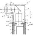
- FIG. 2 is a schematic cross-sectional view of an optical unit 6 of the projector 100 shown in FIG.
- FIG. 2 is a schematic diagram for explaining a detailed position of a contact point in an optical unit 6 of the projector 100 shown in FIG.
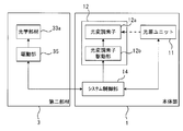
- FIG. 2 is a diagram showing an internal block configuration of the projector 100 shown in FIG.
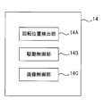
- FIG. 6 is a functional block diagram of a system control unit 14 shown in FIG. It is a cross section of an optical unit 6A which is a modification of the optical unit 6.
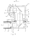
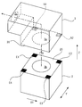
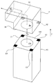
- FIG. 8 is a schematic exploded perspective view of the optical unit 6A shown in FIG. 7.
- FIG. 1 is a schematic diagram showing an external configuration of a projector 100 which is an embodiment of the projection device of the present invention.
- FIG. 2 is a schematic diagram illustrating an example of the internal configuration of the light source unit 11 of FIG.
- FIG. 3 is a schematic sectional view of the optical unit 6 of the projector 100 shown in FIG. FIG. 3 shows a cross section of a surface along the optical path of light emitted from the main body 1.
- the projector 100 includes a main body 1 and an optical unit 6 provided to protrude from the main body 1.
- the main body 1 has a housing 15 (see FIG. 3) in which an opening 15a (see FIG. 3) for transmitting light is formed at a portion connected to the optical unit 6.
- a light source unit 11 and a light modulation element 12a for spatially modulating light emitted from the light source unit 11 based on image data are provided inside a housing 15 of the main body 1 (see FIG. 2).
- a light modulation unit 12 including
- the light source unit 11 includes a light source 41 that emits white light, a color wheel 42, and an illumination optical system 43.
- the light source 41 is configured to include a light emitting element such as a laser or an LED (Light Emitting Diode).
- the color wheel 42 is disposed between the light source 41 and the illumination optical system 43.
- the color wheel 42 is a disk-shaped member, and is provided along its circumferential direction with an R filter that transmits red light, a G filter that transmits green light, and a B filter that transmits blue light.
- the color wheel 42 is rotated around an axis, and splits white light emitted from the light source 41 into red light, green light, and blue light in a time division manner and guides the white light to the illumination optical system 43.
- the light emitted from the illumination optical system 43 enters the light modulation element 12a.
- the light modulation element 12a included in the light modulation unit 12 for example, a DMD (Digital Micromirror Device) is used if the light source unit 11 has the configuration of FIG.
- a DMD Digital Micromirror Device
- an LCOS Liquid Crystal On Silicon
- MEMS Micro Electro Mechanical Systems
- a liquid crystal display element or the like can be used.
- the light spatially modulated by the light modulation unit 12 passes through the opening 15 a of the housing 15 and enters the optical unit 6.
- the optical unit 6 includes a first member 2 having a hollow portion 2A connected to the inside of the main body 1, a second member 3 having a hollow portion 3A connected to the hollow portion 2A, and a hollow portion 2A.
- the first optical system 21 and the reflecting member 22 disposed, the second optical system 31, the reflecting member 32, the third optical system 33, the driving unit 35, and the lens 34 disposed in the hollow portion 3A; A mechanism 4.
- the first member 2 is a member having a rectangular cross section, and the openings 2a and the openings 2b are formed on surfaces perpendicular to each other.
- the first member 2 is supported by the main body 1 in a state where the opening 2a is arranged at a position facing the opening 15a of the main body 1.
- Light emitted from the light modulation unit 12 of the main body 1 is incident on the hollow portion 2A of the first member 2 through the opening 15a and the opening 2a.
- the incident direction of light incident on the hollow portion 2A from the main body 1 is defined as a direction X1.
- the reflecting member 22 disposed in the hollow portion 2A of the first member 2 reflects light incident from the main body 1 in a direction Z that is a direction perpendicular to the direction X1.
- the reflection member 22 is configured by, for example, a half mirror, a beam splitter, a polarization member, or the like.
- the first optical system 21 disposed in the hollow portion 2A of the first member 2 is disposed between the reflection member 22 and the main body 1 and includes at least one lens.
- the light that enters the first member 2 from the main body 1 and travels in the direction X1 passes through the first optical system 21, is reflected by the reflection member 22, and travels in the direction Z.
- the first member 2 has an opening 2b formed on the optical path of the light reflected by the reflecting member 22.
- the reflected light passes through the opening 2b and proceeds to the hollow portion 3A of the second member 3.
- the projector 100 is installed and used so that the direction Z is opposite to the vertical direction.
- the rotation mechanism 4 is a mechanism for rotatably connecting the second member 3 to the first member 2.
- the second member 3 is configured to be rotatable around a rotation axis parallel to the direction Z (specifically, an axis extending in the direction Z passing through the center of the opening 2b).
- the second member 3 is a member having a substantially L-shaped cross section, and an opening 3 a is formed at a position facing the opening 2 b of the first member 2. Light from the main body 1 passing through the opening 2b of the first member 2 is incident on the hollow portion 3A of the second member 3 through the opening 3a.
- the reflecting member 32 disposed in the hollow portion 3A of the second member 3 reflects the light incident from the first member 2 in the direction X2 which is a direction perpendicular to the direction Z.
- the reflecting member 32 is configured by, for example, a half mirror, a beam splitter, a polarizing member, or the like.
- the second optical system 31 disposed in the hollow portion 3A of the second member 3 is disposed between the reflection member 32 and the first member 2, and includes at least one lens.
- the lens 34 disposed in the hollow portion 3A of the second member 3 is disposed at the end of the second member 3 so as to close the opening 3c formed at the end opposite to the opening 3a.
- the lens 34 is disposed in the traveling direction of the light reflected by the reflection member 32, and the light emitted from the lens 34 is projected on a projection surface.
- the third optical system 33 disposed in the hollow portion 3A of the second member 3 is disposed between the lens 34 and the reflection member 32, and includes at least one lens.
- the third optical system 33 includes a movable optical member 33a.
- the optical member 33a is, for example, a focus lens for adjusting a focal position, a zoom lens for adjusting a focal length, or a variable stop that allows a variable amount of transmitted light.
- the drive unit 35 is an actuator such as a solenoid or a motor for driving the optical member 33a, and is controlled by a system control unit 14 described later.
- the light from the main body 1 that has entered the hollow portion 3A of the second member 3 passes through the second optical system 31, is reflected by the reflecting member 32, travels in the direction X2, and then travels in the third optical system.
- the light passes through 33 and is projected from the lens 34 toward the projection surface.
- Two movable portion side contacts (electrodes) N1 and N2 are formed at the contact portion of the second member 3 with the first member 2.
- the movable-part-side contact N1 is electrically connected to a plus-side power terminal of the driving unit 35 via a wiring (not shown).
- the movable-part-side contact N2 is electrically connected to a minus power supply terminal of the drive unit 35 via a wiring (not shown).
- FIG. 4 is a schematic diagram for explaining a detailed position of a contact point in the optical unit 6 of the projector 100 shown in FIG.
- the first member 2 has a surface 2 ⁇ / b> S perpendicular to the rotation axis (the axis extending in the direction Z) of the rotation mechanism 4 as a portion that contacts the second member 3.
- the four fixed portion side contacts E1, E2, E3, E4 are arranged in a square lattice in the direction Y perpendicular to the direction X1 and the direction Z and in the direction X1.
- the direction X1 forms a first direction
- the direction Y forms a second direction.
- the second member 3 has a surface 3S perpendicular to the rotation axis of the rotation mechanism 4 as a portion that comes into contact with the first member 2.
- the two movable portion side contacts N1 and N2 are arranged in the direction X1.
- the arrangement interval between the movable portion side contact N1 and the movable portion side contact N2 includes the arrangement interval between the fixed portion side contact E1 and the fixed portion side contact E2, the arrangement interval between the fixed portion side contact E2 and the fixed portion side contact E3, the fixed portion side contact.
- the arrangement interval between E3 and the fixed portion side contact E4 and the arrangement interval between the fixed portion side contact E4 and the fixed portion side contact E1 are the same.
- the movable portion side contacts N1 and N2 formed on the second member 3 are, as described below, of the fixed portion side contacts E1, E2, E3 and E4 depending on the rotational position of the second member 3 with respect to the first member 2. Contact two adjacent contacts.
- the movable portion side contact N1 contacts the fixed portion side contact E3
- the movable portion side contact N2 contacts the fixed portion side contact E4.
- a third contact state results.
- the rotational position of the second member 3 in the third contact state is also referred to as a 180-degree rotational position.
- the second member 3 is configured to be rotatable with respect to the first member 2. Therefore, when the second member 3 is at the rotational position shown in FIG. 3, the projection direction of the light projected from the lens 34 is opposite to the direction X1.
- the projection direction of the light projected from the lens 34 is a direction Y perpendicular to the direction X1 and the direction Z (the plane of FIG. 3). (Forward or backward) of the image.
- the projection direction of the light projected from the lens 34 is the same as the direction X1.
- the projector 100 can change the light projection direction into a plurality of directions (four directions in the above example) by rotating the second member 3 by the rotation mechanism 4.
- the first member 2 and the main body 1 constitute a fixed portion
- the second member 3 constitutes a movable portion rotatable with respect to the fixed portion
- FIG. 5 is a diagram showing an internal block configuration of the projector 100 shown in FIG.
- the main body 1 of the projector 100 includes a light source unit 11, a light modulation unit 12 including a light modulation element 12a and a light modulation element driving unit 12b that drives the light modulation element 12a, a system control unit 14 that performs overall control of the whole, and , Are provided.
- the light modulation element driving unit 12b drives the light modulation element 12a based on the image data input from the system control unit 14, and spatially modulates the light from the light source unit 11 with the image data.
- the system control unit 14 includes various processors, a ROM (Read Only Memory), and a RAM (Random Access Memory).
- a programmable logic (CPU) Central Processing Unit
- CPU Central Processing Unit
- FPGA Field Programmable Gate Array
- a dedicated electrical circuit or the like which is a processor having a circuit configuration designed to execute a specific process such as a device (Programmable Logic Device: PLD) or an ASIC (Application Specific Integrated Circuit), is included.
- the structure of these various processors is, more specifically, an electric circuit in which circuit elements such as semiconductor elements are combined.
- the processor of the system control unit 14 may be constituted by one of various processors, or a combination of two or more processors of the same type or different types (for example, a combination of a plurality of FPGAs or a combination of a CPU and an FPGA). May be configured.
- the system control unit 14 determines that the contact state between the movable unit side contacts N1 and N2 and the fixed unit side contacts E1-E4 is the first contact state, the second contact state, the third contact state, and the fourth contact state. Is electrically connected to the driving unit 35 incorporated in the second member 3.
- FIG. 6 is a functional block diagram of the system control unit 14 shown in FIG.
- the processor of the system control unit 14 functions as a rotation position detection unit 14A, a drive control unit 14B, and an image control unit 14C by executing an application program including a control program.
- the rotational position detector 14A detects the rotational position of the second member 3 based on the positions of the fixed-part-side contacts E1-E4 that are in contact with the movable-part-side contacts N1, N2.
- the rotational position detector 14A monitors, for example, the potential of each of the fixed-part-side contacts E1-E4, so that one of the fixed-part-side contacts E1-E4 comes into contact with the movable-part-side contacts N1 and N2. To detect When detecting that the fixed-part-side contacts E1 and E2 are in contact with the movable-part-side contacts N1 and N2, the rotational position detector 14A determines that the rotational position of the second member 3 is the reference position. Is detected.
- the rotational position detector 14A sets the rotational position of the second member 3 to the right 90-degree rotational position. Detect that.
- the rotational position detector 14A determines that the rotational position of the second member 3 is a 180-degree rotational position. Is detected.
- the rotation position detection unit 14A sets the rotation position of the second member 3 to the 90-degree left rotation position. Detect that.
- the drive control unit 14B controls the drive unit 35 by supplying electricity to the fixed unit side contacts that are in contact with the movable unit side contacts N1 and N2.
- the movable section side contact N1 is connected to the positive power supply terminal of the drive section 35.
- the movable portion side contact N2 is connected to a power terminal on the minus side of the driving portion 35.
- the drive control unit 14B sets the potential of the fixed unit side contact E1 in contact with the movable unit side contact N1 to the plus side. Then, power is supplied to the fixed-part-side contacts E1 and E2 so that the potential of the fixed-part-side contact E2 that contacts the movable-part-side contact N2 is negative.
- the drive control unit 14B increases the potential of the fixed-part-side contact E2 that contacts the movable-part-side contact N1. , So that the electric potential is applied to the fixed-part-side contacts E2 and E3 so that the potential of the fixed-part-side contact E3 that comes into contact with the movable-part-side contact N2 becomes negative.
- the drive control unit 14B determines that the potential of the fixed unit side contact E3 that contacts the movable unit side contact N1 is positive. Then, power is supplied to the fixed-part-side contacts E3 and E4 so that the potential of the fixed-part-side contact E4 that contacts the movable-part-side contact N2 becomes negative.
- the drive control unit 14B increases the potential of the fixed unit side contact E4 that contacts the movable unit side contact N1. And the electric contacts are supplied to the fixed-part contacts E4 and E1 so that the potential of the fixed-part contact E1 that contacts the movable-part contact N2 becomes negative.
- the system control unit 14 sends the drive unit Power is supplied to the optical member 35, and the optical member 33a can be driven by the driving unit 35.
- the image controller 14C changes the image projected on the projection surface from the lens 34 by changing the image data input to the light modulator driving unit 12b.
- the image control unit 14C changes the direction of the image data input to the light modulation element driving unit 12b based on the rotation position of the second member 3 detected by the rotation position detection unit 14A.
- the image control unit 14C sets the projection surface on the projection surface even when the rotational position of the second member 3 is any of the reference position, the right 90 ° rotational position, the 180 ° rotational position, and the left 90 ° rotational position.
- the upper end of the projected image is located on the upper side in the vertical direction
- the lower end of the image projected on the projection plane is located on the lower side in the vertical direction (in other words, the upper and lower sides of the image coincide with the upper and lower sides of the projection plane).
- the image data input to the light modulation element driving unit 12b is controlled.
- the image control unit 14C sets the rotation position of the second member 3 to 90 When it is at the rotation position, the direction of the image data input to the light modulation element driving unit 12b is rotated right by 90 degrees with respect to the reference.
- the image control unit 14C rotates the direction of the image data input to the light modulation element driving unit 12b by 180 degrees with respect to the reference.
- the image control unit 14C rotates the direction of the image data input to the light modulation element driving unit 12b 90 degrees to the left with respect to the reference.
- the projector 100 even if the rotation position of the second member 3 is any one of the reference position, the right rotation position by 90 degrees, the rotation position by 180 degrees, and the rotation position by 90 degrees left, Can be matched with the upper and lower sides of the projection plane, and a change in the projected image due to a change in the projection direction can be eliminated.
- the rotational position of the second member 3 is detected by using the movable-part-side contacts N1 and N2 and the fixed-part-side contacts E1 to E4 for supplying power to the drive unit 35. Therefore, a dedicated sensor for detecting the rotational position is not required, and the manufacturing cost can be reduced.
- the drive unit 35 and the system control unit 14 are electrically connected by the movable unit side contacts N1 and N2 and the fixed unit side contacts E1 to E4. For this reason, even when the second member 3 is rotated frequently, there is no fear that the electrical connection between the drive unit 35 and the system control unit 14 cannot be performed, and the reliability can be improved. Further, as compared with a configuration in which the drive unit 35 and the system control unit 14 are electrically connected using wiring, the structure can be simplified and the manufacturing cost can be reduced.
- system control unit 14 performs control for stopping projection of light on the projection surface when at least one movable-part-side contact is not in contact with any one of the fixed-part-side contacts E1 to E4.
- the system control unit 14 performs, for example, a process of stopping input of image data to the light modulation element driving unit 12b, a process of stopping the light source unit 11, or a process of both of them. Stop projecting light onto the projection surface. This eliminates the need for the user to see the state in which the direction of the projection image changes while the second member 3 is rotating, thereby improving usability.
- FIG. 7 is a schematic cross-sectional view of an optical unit 6 ⁇ / b> A which is a modification of the optical unit 6.
- FIG. 8 is an exploded perspective schematic view of the optical unit 6A shown in FIG.
- the optical unit 6A shown in FIG. 7 has a point that the first member 2 is deleted, a point that the second member 3 is rotatably connected to the main body 1 by the rotating mechanism 4, and that the fixed unit side contacts E1-E4 are the main unit.
- the configuration is the same as that of the optical unit 6 except that it is provided on a surface 15S of the housing 15 of the unit 1 that contacts the second member 3.
- the second member 3 of the optical unit 6A is configured to be rotatable by the rotation mechanism 4 around a rotation axis parallel to a direction Z that is an incident direction of light incident from the main body 1. That is, the optical unit 6A has a configuration in which the projection direction can be changed to a plurality of directions by rotating the entirety.
- the projector 100 having the optical unit 6A is installed and used in a posture in which the direction Z is opposite to the vertical direction.
- the operation of the system control unit 14 of the projector 100 according to the second modification is the same as the operation of the system control unit 14 of the projector 100 according to the embodiment, except that the state illustrated in FIG. It is.
- the direction Z is the incident direction of light incident on the reflecting member 32, the main body 1 forms a fixed part, and the second member 3 forms a movable part.
- the projector 100 having the optical unit 6A even if the rotation of the second member 3 for changing the projection direction is repeated, the electrical connection between the second member 3 and the main body 1 can be maintained, and the dedicated sensor is used. , The rotational position of the second member 3 can be detected and the projection image can be adjusted in accordance with the projection direction.
- the projector 100 shown in FIG. 1 is installed and used so that the direction Z faces in the opposite direction to the vertical direction, the projector 100 is installed such that the direction Z faces in the vertical direction, for example, by hanging it on a ceiling. May be used.
- a posture sensor for detecting the installation posture of the projector 100 is provided on the main body 1 or the first member 2 or the like.
- the image control unit 14C detects that the direction Z is the installation orientation in which the direction Z is opposite to the vertical direction from the detection information of the orientation sensor, the control described above (When the rotation position of the second member 3 is the reference position, the direction of the image data is used as a reference. When the rotation position is a right rotation position of 90 degrees, the image data is rotated 90 degrees to the right with respect to the reference. When the rotation position is 180 degrees, the image data is rotated 180 degrees with respect to the reference, and when the rotation position is 90 degrees to the left, the image data is rotated 90 degrees to the left with respect to the reference). .
- the image control unit 14C detects from the detection information of the above-described posture sensor that the direction Z is the installation posture in which the direction is the vertical direction, the image control unit 14C displays the image when the rotational position of the second member 3 is the reference position.
- the direction of the data is rotated by 180 degrees with respect to the reference.
- the rotation position is at the right rotation position of 90 degrees
- the direction of the image data is rotated by 90 degrees to the left with respect to the reference.
- the rotation position is the rotation position of 180 degrees
- the image data is rotated. Is set to the reference direction, and when the rotation position is at the left 90-degree rotation position, control is performed to rotate the image data direction 90 degrees to the right with respect to the reference.
- the upper and lower sides of the image and the upper and lower sides of the projection plane can always be made to match regardless of the installation posture.
- the number of movable portion side contacts provided on the second member 3 is two, it may be three or more. Further, the number of the fixed portion side contacts provided on the first member 2 or the main body portion 1 is four, but may be five or more.
Landscapes
- Physics & Mathematics (AREA)
- General Physics & Mathematics (AREA)
- Optics & Photonics (AREA)
- Engineering & Computer Science (AREA)
- Multimedia (AREA)
- Signal Processing (AREA)
- Projection Apparatus (AREA)
- Transforming Electric Information Into Light Information (AREA)
Abstract
可動部の回転が繰り返されても、可動部との電気的接続を維持できると共に、専用のセンサを追加することなく、可動部の回転位置を検出して投影方向に応じた投影像の調整を行うことのできる投影装置とその制御方法及びプログラムを提供する。 本体部1及び第一部材2によって回動自在に支持された第二部材3は、反射部材32、可動部側接点N1,N2、可動部側接点N1,N2と電気的に接続された駆動部35、及び駆動部35により駆動される光学部材33aを含む。本体部1は、可動部側接点N1,N2と接触している第一部材2の固定部側接点E1-E4の位置に基づいて第二部材3の回転位置を検出し、可動部側接点N1,N2と接触している固定部側接点E1-E4に通電して駆動部35を制御し、第二部材3の回転位置に基づいて光変調素子駆動部12bに入力する画像データの向きを変更するシステム制御部14を備える。
Description
本発明は、投影装置に関する。
特許文献1には、反射部材を含む投影光学系を収容する光学部を筐体から突出させて設け、この光学部の反射部材を含む部分を回転させることで、投影方向を設置面に水平な面内にて変更することのできる投影装置が記載されている。
特許文献2には、反射部材を筐体から突出させて設け、この反射部材による光の反射方向を変えることで投影方向を設置面に水平な面内にて変更することのできる投影装置が記載されている。
特許文献1及び特許文献2に記載の投影装置は、反射部材の向きに応じて、投影面に投影される投影像の向きを調整することで、投影方向の変化によって投影像が回転しないようにしている。
特許文献3には、光源と投影光学系を収容する本体ケースが、アーム部の支持軸を中心に回動可能にアーム部に取り付けられた投影装置が記載されている。この投影装置は、支持軸に固定された接点が基板に形成された複数のスイッチパターンのどれに接触しているかによって、本体ケースの回転角度を検出し、回転角度に応じて、投影像の台形歪み補正を行っている。
特許文献4には、カメラ本体とレンズユニットとを回動自在に連結することのできるデジタルカメラが記載されている。
特許文献1,2に記載された投影装置のように、投影光学系の一部を回転させることのできる装置において、例えば、通電によって駆動される光学部材(例えば、焦点調節用のレンズ、焦点距離調節用のレンズ、又は可変絞り等)が可動部に含まれる場合を想定する。この場合、可動部と、通電制御を行うための制御装置が収容される本体部とを電気的に接続する必要がある。しかし、可動部と本体部を配線によって接続する構成では、可動部が頻繁に回転されることで、配線が破損する可能性がある。また、可動部の回転に耐え得る設計が必要となり、装置の製造コストが増大する。
特許文献1,2では、可動部に通電することは考慮しておらず、上述した課題の認識はない。特許文献3に記載の投影装置は、可動の本体ケースとそれを支持するアーム部との間の通電は行っておらず、上述した課題の認識はない。
また、特許文献1,2に記載されているように、投影方向に応じて投影像の向きが変化しないような制御を行うためには、可動部の回転位置を検出する必要がある。特許文献1-3では、可動部の回転位置を検出するためのセンサを専用に設けているため、装置の製造コストが増大する。特許文献4では、カメラ本体に対するレンズユニットの回転角度を、ホール素子又はピンを用いた手段によって検出している。このため、回転位置の検出のためのコストは大きくなる。
本発明は、上記事情に鑑みてなされたものであり、投影方向を変えるための可動部の回転が繰り返されても、可動部との電気的接続を維持できると共に、専用のセンサを追加することなく、可動部の回転位置を検出して投影方向に応じた投影像の調整を行うことのできる投影装置を提供することを目的とする。
本発明の投影装置は、投影装置であって、光源及び上記光源からの光を画像データに基づいて空間変調する光変調素子を内蔵する固定部と、上記固定部から出射された光を反射させる反射部材を含み、上記反射部材への上記光の入射方向に平行な回転軸の回りに上記固定部によって回転自在に支持され、上記固定部に対して可動する可動部と、上記固定部の上記可動部と接触する部分に形成された固定部側電極と、上記可動部の上記固定部と接触する部分に形成された可動部側電極と、上記可動部に設けられ、上記可動部側電極と電気的に接続された駆動部と、上記可動部に設けられ、上記駆動部により駆動される光学部材と、を備え、上記固定部は、上記可動部側電極が上記固定部側電極と通電している際に、上記駆動部を制御する駆動制御部を備えるものである。
本発明によれば、投影方向を変えるための可動部の回転が繰り返されても、可動部との電気的接続を維持できると共に、専用のセンサを追加することなく、可動部の回転位置を検出して投影方向に応じた投影像の調整を行うことのできる投影装置を提供することができる。
以下、本発明の実施形態について図面を参照して説明する。
図1は、本発明の投影装置の一実施形態であるプロジェクタ100の外観構成を示す模式図である。図2は、図1の光源ユニット11の内部構成の一例を示す模式図である。図3は、図1に示すプロジェクタ100の光学ユニット6の断面模式図である。図3は、本体部1から出射される光の光路に沿った面での断面を示している。
図1に示すように、プロジェクタ100は、本体部1と、本体部1から突出して設けられた光学ユニット6と、を備える。
本体部1は、光学ユニット6と連結される部分に光を通すための開口15a(図3参照)が形成された筐体15(図3参照)を有する。
本体部1の筐体15の内部には、図1に示すように、光源ユニット11と、光源ユニット11から出射される光を画像データに基づいて空間変調する光変調素子12a(図2参照)を含む光変調ユニット12と、が設けられている。
図2に示す例では、光源ユニット11は、白色光を出射する光源41と、カラーホイール42と、照明光学系43と、を備える。光源41は、レーザ又はLED(Light Emitting Diode)等の発光素子を含んで構成される。カラーホイール42は、光源41と照明光学系43の間に配置されている。カラーホイール42は、円板状の部材であり、その周方向に沿って、赤色光を透過するRフィルタ、緑色光を透過するGフィルタ、及び青色光を透過するBフィルタが設けられている。カラーホイール42は軸周りに回転され、光源41から出射される白色光を時分割にて赤色光、緑色光、及び青色光に分光して照明光学系43に導く。照明光学系43から出射された光は光変調素子12aに入射される。
光変調ユニット12に含まれる光変調素子12aは、図2の光源ユニット11の構成であればDMD(Digital Micromirror Device)が例えば用いられる。光変調素子12aとしては、LCOS(Liquid crystal on silicon)、MEMS(Micro Electro Mechanical Systems)素子、又は液晶表示素子等を用いることもできる。光変調ユニット12によって空間変調された光は、筐体15の開口15aを通過して光学ユニット6に入射される。
図3に示すように、光学ユニット6は、本体部1の内部と繋がる中空部2Aを有する第一部材2と、中空部2Aと繋がる中空部3Aを有する第二部材3と、中空部2Aに配置された第一の光学系21及び反射部材22と、中空部3Aに配置された第二の光学系31、反射部材32、第三の光学系33、駆動部35、及びレンズ34と、回転機構4と、を備える。
第一部材2は、断面外形が矩形の部材であり、開口2aと開口2bが互いに垂直な面に形成されている。第一部材2は、本体部1の開口15aと対面する位置に開口2aが配置される状態にて、本体部1によって支持されている。本体部1の光変調ユニット12から出射された光は、開口15a及び開口2aを通って第一部材2の中空部2Aに入射される。本体部1から中空部2Aに入射される光の入射方向を方向X1と定義する。
第一部材2の中空部2Aに配置された反射部材22は、本体部1から入射される光を方向X1に垂直な方向である方向Zに反射させる。反射部材22は、例えばハーフミラー、ビームスプリッター、又は偏光部材等によって構成される。
第一部材2の中空部2Aに配置された第一の光学系21は、反射部材22と本体部1の間に配置されており、少なくとも1つのレンズを含む。
本体部1から第一部材2に入射された方向X1に進む光は、第一の光学系21を通過した後、反射部材22によって反射されて方向Zに進む。第一部材2には、反射部材22にて反射した光の光路上に開口2bが形成されており、この反射した光は開口2bを通過して第二部材3の中空部3Aへと進む。プロジェクタ100は、方向Zが鉛直方向の反対を向くように設置されて使用される。
回転機構4は、第一部材2に対して第二部材3を回転自在に連結する機構である。この回転機構4によって、第二部材3は、方向Zに平行な回転軸(具体的には、開口2bの中心を通る方向Zに延びる軸)の回りに回転自在に構成されている。
第二部材3は、断面外形が略L字状の部材であり、第一部材2の開口2bと対面する位置に開口3aが形成されている。第一部材2の開口2bを通過した本体部1からの光は、この開口3aを通って第二部材3の中空部3Aに入射される。
第二部材3の中空部3Aに配置された反射部材32は、第一部材2から入射される光を方向Zに垂直な方向である方向X2に反射させる。反射部材32は、例えばハーフミラー、ビームスプリッター、又は偏光部材等によって構成される。
第二部材3の中空部3Aに配置された第二の光学系31は、反射部材32と第一部材2の間に配置されており、少なくとも1つのレンズを含む。
第二部材3の中空部3Aに配置されたレンズ34は、第二部材3の開口3a側と反対側の端部に形成された開口3cを塞ぐ形でこの端部に配置されている。レンズ34は、反射部材32により反射された光の進行方向に配置されており、ここから出射される光が投影面に投影される。
第二部材3の中空部3Aに配置された第三の光学系33は、レンズ34と反射部材32の間に配置されており、少なくとも1つのレンズを含む。第三の光学系33には、可動の光学部材33aが含まれる。光学部材33aは、例えば、焦点位置を調節するためのフォーカスレンズ、焦点距離を調節するためのズームレンズ、又は透過光量が可変の可変絞り等である。
駆動部35は、光学部材33aを駆動するソレノイド又はモータ等のアクチュエータであり、後述のシステム制御部14によって制御される。
第二部材3の中空部3Aに入射した本体部1からの光は、第二の光学系31を通過した後、反射部材32にて反射されて方向X2に進み、その後、第三の光学系33を通過してレンズ34から投影面に向けて投影される。
第一部材2における第二部材3との接触部分には、4つの固定部側接点(電極)E1,E2,E3,E4が形成されている。固定部側接点E1,E2,E3,E4の各々は、図示省略の配線を介して後述のシステム制御部14と電気的に接続されている。
第二部材3における第一部材2との接触部分には、2つの可動部側接点(電極)N1,N2が形成されている。可動部側接点N1は、図示省略の配線を介して、駆動部35のプラス側の電源端子と電気的に接続されている。可動部側接点N2は、図示省略の配線を介して、駆動部35のマイナス側の電源端子と電気的に接続されている。
図4は、図1に示すプロジェクタ100の光学ユニット6における接点の詳細位置を説明するための模式図である。図4に示すように、第一部材2は、回転機構4の回転軸(方向Zに延びる軸)に垂直な面2Sを、第二部材3と接触する部分として有する。この面2Sにおいて、4つの固定部側接点E1,E2,E3,E4は、方向X1及び方向Zに垂直な方向Yと、方向X1とに正方格子状に配列されている。方向X1は第一の方向を構成し、方向Yは第二の方向を構成する。
また、第二部材3は、回転機構4の回転軸に垂直な面3Sを、第一部材2と接触する部分として有する。この面3Sにおいて、2つの可動部側接点N1,N2は、方向X1に配列されている。可動部側接点N1と可動部側接点N2の配置間隔は、固定部側接点E1と固定部側接点E2の配置間隔、固定部側接点E2と固定部側接点E3の配置間隔、固定部側接点E3と固定部側接点E4の配置間隔、及び、固定部側接点E4と固定部側接点E1の配置間隔と同じになっている。
第二部材3に形成された可動部側接点N1,N2は、第二部材3の第一部材2に対する回転位置によって、以下のように、固定部側接点E1,E2,E3,E4のうちの隣り合う2つの接点と接触する。
レンズ34の光軸方向と方向X1とが平行になる第二部材3の回転位置(図3に示す回転位置)においては、可動部側接点N1と固定部側接点E1が接触し、可動部側接点N2と固定部側接点E2が接触する第一の接触状態となる。この第一の接触状態となるときの第二部材3の回転位置を基準位置ともいう。
図3の状態から、第二部材3が右回り(紙面奥側)に90度回転した回転位置においては、可動部側接点N1と固定部側接点E2が接触し、可動部側接点N2と固定部側接点E3が接触する第二の接触状態となる。この第二の接触状態となるときの第二部材3の回転位置を右90度回転位置ともいう。
図3の状態から、第二部材3が180度回転した回転位置においては、可動部側接点N1と固定部側接点E3が接触し、可動部側接点N2と固定部側接点E4が接触する第三の接触状態となる。この第三の接触状態となるときの第二部材3の回転位置を180度回転位置ともいう。
図3の状態から、第二部材3が左回り(紙面手前側)に90度回転した回転位置においては、可動部側接点N1と固定部側接点E4が接触し、可動部側接点N2と固定部側接点E1が接触する第四の接触状態となる。この第四の接触状態となるときの第二部材3の回転位置を左90度回転位置ともいう。
光学ユニット6では、第二部材3が第一部材2に対して回転自在に構成されている。このため、第二部材3が図3に示す回転位置にあるときには、レンズ34から投影される光の投影方向は、方向X1の反対方向となる。また、第二部材3が、図3の状態に対し90度回転した位置にあるときには、レンズ34から投影される光の投影方向は、方向X1及び方向Zに垂直な方向Y(図3の紙面の手前方向又は奥方向)となる。また、第二部材3が、例えば図3の状態に対し180度回転した位置にあるときには、レンズ34から投影される光の投影方向は、方向X1と同じ方向となる。
このように、プロジェクタ100は、回転機構4によって第二部材3を回転させることで、光の投影方向を複数の方向(上記の例では4つの方向)に変えることができるようになっている。
プロジェクタ100において、第一部材2と本体部1は固定部を構成し、第二部材3はこの固定部に対し回動自在に構成された可動部を構成する。
図5は、図1に示すプロジェクタ100の内部ブロック構成を示す図である。プロジェクタ100の本体部1には、光源ユニット11と、光変調素子12a及び光変調素子12aを駆動する光変調素子駆動部12bを含む光変調ユニット12と、全体を統括制御するシステム制御部14と、が設けられている。
光変調素子駆動部12bは、システム制御部14から入力される画像データに基づいて光変調素子12aを駆動し、光源ユニット11からの光をこの画像データによって空間変調させる。
システム制御部14は、各種のプロセッサと、ROM(Read Only Memory)と、RAM(Random Accsess Memory)と、を備える。
各種のプロセッサとしては、プログラムを実行して各種処理を行う汎用的なプロセッサであるCPU(Central Prosessing Unit)、FPGA(Field Programmable Gate Array)等の製造後に回路構成を変更可能なプロセッサであるプログラマブルロジックデバイス(Programmable Logic Device:PLD)、又はASIC(Application Specific Integrated Circuit)等の特定の処理を実行させるために専用に設計された回路構成を有するプロセッサである専用電気回路等が含まれる。
これら各種のプロセッサの構造は、より具体的には、半導体素子等の回路素子を組み合わせた電気回路である。
システム制御部14のプロセッサは、各種のプロセッサのうちの1つで構成されてもよいし、同種又は異種の2つ以上のプロセッサの組み合わせ(例えば、複数のFPGAの組み合わせ又はCPUとFPGAの組み合わせ)で構成されてもよい。
システム制御部14は、可動部側接点N1,N2と固定部側接点E1-E4との接触状態が、上記の第一の接触状態、第二の接触状態、第三の接触状態、及び第四の接触状態のいずれかであるときに、第二部材3に内蔵された駆動部35と電気的に接続される。
図6は、図5に示すシステム制御部14の機能ブロック図である。システム制御部14のプロセッサは、制御プログラムを含むアプリケーションプログラムを実行することにより、回転位置検出部14A、駆動制御部14B、及び画像制御部14Cとして機能する。
回転位置検出部14Aは、可動部側接点N1,N2と接触している固定部側接点E1-E4の位置に基づいて、第二部材3の回転位置を検出する。
回転位置検出部14Aは、例えば、固定部側接点E1-E4の各々の電位をモニタすることで、固定部側接点E1-E4のうちのどれが、可動部側接点N1,N2に接触しているかを検出する。そして、回転位置検出部14Aは、固定部側接点E1,E2が可動部側接点N1,N2に接触していることを検出した場合には、第二部材3の回転位置が基準位置であることを検出する。
回転位置検出部14Aは、固定部側接点E2,E3が可動部側接点N1,N2に接触していることを検出した場合には、第二部材3の回転位置が右90度回転位置であることを検出する。
回転位置検出部14Aは、固定部側接点E3,E4が可動部側接点N1,N2に接触していることを検出した場合には、第二部材3の回転位置が180度回転位置であることを検出する。
回転位置検出部14Aは、固定部側接点E4,E1が可動部側接点N1,N2に接触していることを検出した場合には、第二部材3の回転位置が左90度回転位置であることを検出する。
駆動制御部14Bは、可動部側接点N1,N2と接触している固定部側接点に通電して駆動部35を制御する。上述したように、可動部側接点N1は、駆動部35のプラス側の電源端子に接続されている。また、可動部側接点N2は、駆動部35のマイナス側の電源端子に接続されている。
したがって、回転位置検出部14Aによって回転位置が基準位置であることが検出された場合には、駆動制御部14Bは、可動部側接点N1に接触する固定部側接点E1の電位がプラス側になり、可動部側接点N2に接触する固定部側接点E2の電位がマイナス側となるように、固定部側接点E1,E2に通電を行う。
また、回転位置検出部14Aによって回転位置が右90度回転位置であることが検出された場合には、駆動制御部14Bは、可動部側接点N1に接触する固定部側接点E2の電位がプラス側になり、可動部側接点N2に接触する固定部側接点E3の電位がマイナス側となるように、固定部側接点E2,E3に通電を行う。
また、回転位置検出部14Aによって回転位置が180度回転位置であることが検出された場合には、駆動制御部14Bは、可動部側接点N1に接触する固定部側接点E3の電位がプラス側になり、可動部側接点N2に接触する固定部側接点E4の電位がマイナス側となるように、固定部側接点E3,E4に通電を行う。
また、回転位置検出部14Aによって回転位置が左90度回転位置であることが検出された場合には、駆動制御部14Bは、可動部側接点N1に接触する固定部側接点E4の電位がプラス側になり、可動部側接点N2に接触する固定部側接点E1の電位がマイナス側となるように、固定部側接点E4,E1に通電を行う。
これらの通電制御によって、第二部材3の回転位置が、基準位置、右90度回転位置、180度回転位置、及び左90度回転位置のいずれであった場合でも、システム制御部14から駆動部35への通電がなされ、駆動部35によって光学部材33aの駆動が可能となる。
画像制御部14Cは、光変調素子駆動部12bに入力する画像データを変更することで、レンズ34から投影面に投影される画像を変更する。画像制御部14Cは、回転位置検出部14Aにより検出された第二部材3の回転位置に基づいて、光変調素子駆動部12bに入力する画像データの向きを変更する。
具体的には、画像制御部14Cは、第二部材3の回転位置が基準位置、右90度回転位置、180度回転位置、及び左90度回転位置のいずれであった場合でも、投影面に投影される画像の上端が鉛直方向の上側に位置し且つ投影面に投影される画像の下端が鉛直方向の下側に位置する(言い換えると、画像の上下と投影面の上下が一致する)ように、光変調素子駆動部12bに入力する画像データを制御する。
画像制御部14Cは、例えば、第二部材3の回転位置が基準位置にある場合に光変調素子駆動部12bに入力する画像データの向きを基準とすると、第二部材3の回転位置が右90度回転位置にある場合には、光変調素子駆動部12bに入力する画像データの向きを基準に対し右に90度回転させる。
画像制御部14Cは、第二部材3の回転位置が180度回転位置にある場合には、光変調素子駆動部12bに入力する画像データの向きを基準に対し180度回転させる。
画像制御部14Cは、第二部材3の回転位置が左90度回転位置にある場合には、光変調素子駆動部12bに入力する画像データの向きを基準に対し左に90度回転させる。
以上のように、プロジェクタ100によれば、第二部材3の回転位置が基準位置、右90度回転位置、180度回転位置、及び左90度回転位置のいずれであった場合でも、画像の上下を投影面の上下と一致させることができ、投影方向の変更による投影画像の変化をなくすことができる。
また、プロジェクタ100によれば、第二部材3の回転位置を、駆動部35への通電を行うための可動部側接点N1,N2及び固定部側接点E1-E4を用いて検出している。このため、回転位置を検出するための専用のセンサが不要となり、製造コストを低減することができる。
また、プロジェクタ100によれば、駆動部35とシステム制御部14との電気的接続が、可動部側接点N1,N2及び固定部側接点E1-E4によって行われる。このため、第二部材3が頻繁に回転された場合でも、駆動部35とシステム制御部14との電気的接続ができなくなる心配はなく、信頼性の向上を図ることができる。また、配線を用いて駆動部35とシステム制御部14を電気的に接続する構成と比較すると、構造を簡素化することができ、製造コストを下げることができる。
次に、プロジェクタ100の変形例について説明する。
(第一の変形例)
システム制御部14は、少なくとも1つの可動部側接点が固定部側接点E1-E4のいずれかと非接触の状態では、投影面への光の投影を停止させる制御を行うのが好ましい。
システム制御部14は、少なくとも1つの可動部側接点が固定部側接点E1-E4のいずれかと非接触の状態では、投影面への光の投影を停止させる制御を行うのが好ましい。
第二部材3が回転中であり、第二部材3の回転位置が基準位置、右90度回転位置、180度回転位置、及び左90度回転位置のいずれでもない場合には、可動部側接点N1,N2と固定部側接点E1-E4とは接触しない状態になる。この状態においては、システム制御部14は、例えば、光変調素子駆動部12bに画像データを入力するのを停止する処理、光源ユニット11を停止させる処理、又はこれら両方の処理等を行うことで、投影面への光の投影を停止させる。これにより、第二部材3の回転中に、投影画像の向きが変化する状態をユーザに見せずにすむため、ユーザビリティを向上させることができる。
(第二の変形例)
図7は、光学ユニット6の変形例である光学ユニット6Aの断面模式図である。図8は、図7に示す光学ユニット6Aの分解斜視模式図である。
図7は、光学ユニット6の変形例である光学ユニット6Aの断面模式図である。図8は、図7に示す光学ユニット6Aの分解斜視模式図である。
図7に示す光学ユニット6Aは、第一部材2が削除された点、第二部材3が回転機構4によって本体部1に対し回転自在に連結された点、固定部側接点E1-E4が本体部1の筐体15における第二部材3と接触する面15Sに設けられている点を除いては、光学ユニット6と同じ構成である。
この光学ユニット6Aの第二部材3は、回転機構4によって、本体部1から入射される光の入射方向である方向Zに平行な回転軸の回りに回転自在に構成されている。つまり、光学ユニット6Aは、全体を回転させて投影方向を複数の方向に変えることのできる構成である。
光学ユニット6Aを有するプロジェクタ100は、方向Zが鉛直方向の反対方向になる姿勢にて設置されて使用される。第二の変形例のプロジェクタ100のシステム制御部14の動作は、図7に示す状態が第二部材3の基準位置とされる以外は、実施形態のプロジェクタ100のシステム制御部14の動作と同じである。
光学ユニット6Aにおいては、方向Zが反射部材32に入射する光の入射方向となり、本体部1が固定部を構成し、第二部材3が可動部を構成する。光学ユニット6Aを有するプロジェクタ100によれば、投影方向を変えるための第二部材3の回転が繰り返されても、第二部材3と本体部1との電気的接続を維持できると共に、専用のセンサを追加することなく、第二部材3の回転位置を検出して投影方向に応じた投影像の調整を行うことができる。
(第三の変形例)
図1に示すプロジェクタ100は、方向Zが鉛直方向の反対を向くように設置されて使用されるものとしたが、例えば天井に吊り下げる等して、方向Zが鉛直方向を向くように設置されて使用可能なものとしてもよい。この場合には、プロジェクタ100の設置姿勢を検出するための姿勢センサが、本体部1又は第一部材2等に設けられる。
図1に示すプロジェクタ100は、方向Zが鉛直方向の反対を向くように設置されて使用されるものとしたが、例えば天井に吊り下げる等して、方向Zが鉛直方向を向くように設置されて使用可能なものとしてもよい。この場合には、プロジェクタ100の設置姿勢を検出するための姿勢センサが、本体部1又は第一部材2等に設けられる。
第三の変形例のプロジェクタ100では、画像制御部14Cは、上記の姿勢センサの検出情報から、方向Zが鉛直方向の反対を向く設置姿勢であることを検出した場合には、上述した制御(第二部材3の回転位置が基準位置のときは画像データの向きを基準にし、回転位置が右90度回転位置のときは画像データの向きを基準に対し右に90度回転させ、回転位置が180度回転位置のときは画像データの向きを基準に対し180度回転させ、回転位置が左90度回転位置にあるときは画像データの向きを基準に対し左に90度回転させる制御)を行う。
一方、画像制御部14Cは、上記の姿勢センサの検出情報から、方向Zが鉛直方向を向く設置姿勢であることを検出した場合には、第二部材3の回転位置が基準位置のときは画像データの向きを基準に対し180度回転させ、回転位置が右90度回転位置のときは画像データの向きを基準に対し左に90度回転させ、回転位置が180度回転位置のときは画像データの向きを基準の向きにし、回転位置が左90度回転位置にあるときは画像データの向きを基準に対し右に90度回転させる制御を行う。
このように、プロジェクタ100の設置姿勢に応じて画像データの向きを変えることで、設置姿勢によらずに、画像の上下と投影面の上下とを常時一致させることができる。
(その他の変形例)
第二部材3に設けられる可動部側接点の数は2つとしているが3つ以上であってもよい。また、第一部材2又は本体部1に設けられる固定部側接点の数は4つとしているが5つ以上であってもよい。
第二部材3に設けられる可動部側接点の数は2つとしているが3つ以上であってもよい。また、第一部材2又は本体部1に設けられる固定部側接点の数は4つとしているが5つ以上であってもよい。
以上、図面を参照しながら各種の実施の形態について説明したが、本発明はかかる例に限定されないことは言うまでもない。当業者であれば、特許請求の範囲に記載された範疇内において、各種の変更例又は修正例に想到し得ることは明らかであり、それらについても当然に本発明の技術的範囲に属するものと了解される。また、発明の趣旨を逸脱しない範囲において、上記実施の形態における各構成要素を任意に組み合わせてもよい。
なお、本出願は、2018年7月25日出願の日本特許出願(特願2018-139788)に基づくものであり、その内容は本出願の中に参照として援用される。
本発明によれば、投影方向を変えるための可動部の回転が繰り返されても、可動部との電気的接続を維持できると共に、専用のセンサを追加することなく、可動部の回転位置を検出して投影方向に応じた投影像の調整を行うことのできる投影装置を提供することができる。
100 プロジェクタ
1 本体部
2 第一部材
2S 面
2a,2b 開口
2A 中空部
21 第一の光学系
22 反射部材
3 第二部材
3S 面
3a,2b 開口
3A 中空部
31 第二の光学系
32 反射部材
33 第三の光学系
34 レンズ
4 回転機構
6,6A 光学ユニット
11 光源ユニット
41 光源
42 カラーホイール
43 照明光学系
12 光変調ユニット
12a 光変調素子
12b 光変調素子駆動部
14 システム制御部
14A 回転位置検出部
14B 駆動制御部
14C 画像制御部
15 筐体
15S 面
15a 開口
35 駆動部
33a 光学部材
N1,N2 可動部側接点
E1-E4 固定部側接点
1 本体部
2 第一部材
2S 面
2a,2b 開口
2A 中空部
21 第一の光学系
22 反射部材
3 第二部材
3S 面
3a,2b 開口
3A 中空部
31 第二の光学系
32 反射部材
33 第三の光学系
34 レンズ
4 回転機構
6,6A 光学ユニット
11 光源ユニット
41 光源
42 カラーホイール
43 照明光学系
12 光変調ユニット
12a 光変調素子
12b 光変調素子駆動部
14 システム制御部
14A 回転位置検出部
14B 駆動制御部
14C 画像制御部
15 筐体
15S 面
15a 開口
35 駆動部
33a 光学部材
N1,N2 可動部側接点
E1-E4 固定部側接点
Claims (7)
- 投影装置であって、
光源及び前記光源からの光を画像データに基づいて空間変調する光変調素子を内蔵する固定部と、
前記固定部から出射された光を反射させる反射部材を含み、前記反射部材への前記光の入射方向に平行な回転軸の回りに前記固定部によって回転自在に支持され、前記固定部に対して可動する可動部と、
前記固定部の前記可動部と接触する部分に形成された固定部側電極と、
前記可動部の前記固定部と接触する部分に形成された可動部側電極と、
前記可動部に設けられ、前記可動部側電極と電気的に接続された駆動部と、
前記可動部に設けられ、前記駆動部により駆動される光学部材と、を備え、
前記固定部は、前記可動部側電極が前記固定部側電極と通電している際に、前記駆動部を制御する駆動制御部を備える投影装置。 - 請求項1記載の投影装置であって、
前記駆動制御部は、前記可動部側電極と接触している前記固定部側電極に通電する電流の方向を制御する投影装置。 - 請求項1又は2記載の投影装置であって、
少なくとも1つの前記可動部側電極が前記固定部側電極と非接触の状態では、投影面への光の投影が停止される投影装置。 - 請求項1ないし3のいずれか1項記載の投影装置であって、
前記可動部側電極の数は、前記固定部側電極の数よりも少ない、投影装置。 - 請求項1ないし4のいずれか1項記載の投影装置であって、
前記固定部側電極は、前記回転軸に垂直な面において、第一の方向と前記第一の方向に直交する第二の方向とに正方格子状に配列され、
前記可動部側電極は、前記面において、前記固定部側電極の前記第一の方向における配置間隔と同じ間隔を空けて前記第一の方向に配列される、投影装置。 - 請求項1ないし5のいずれか1項記載の投影装置であって、前記可動部側電極が接触している前記固定部側電極の位置に基づいて前記可動部の回転位置を検出する回転位置検出部を備える、投影装置。
- 請求項1ないし6のいずれか1項記載の投影装置であって、前記可動部の回転位置に基づいて、前記画像データの向きを変更する画像制御部を備える投影装置。
Priority Applications (2)
| Application Number | Priority Date | Filing Date | Title |
|---|---|---|---|
| JP2020532184A JP6831041B2 (ja) | 2018-07-25 | 2019-05-29 | 投影装置 |
| US17/143,751 US11199694B2 (en) | 2018-07-25 | 2021-01-07 | Projection apparatus |
Applications Claiming Priority (2)
| Application Number | Priority Date | Filing Date | Title |
|---|---|---|---|
| JP2018139788 | 2018-07-25 | ||
| JP2018-139788 | 2018-07-25 |
Related Child Applications (1)
| Application Number | Title | Priority Date | Filing Date |
|---|---|---|---|
| US17/143,751 Continuation US11199694B2 (en) | 2018-07-25 | 2021-01-07 | Projection apparatus |
Publications (1)
| Publication Number | Publication Date |
|---|---|
| WO2020021850A1 true WO2020021850A1 (ja) | 2020-01-30 |
Family
ID=69181555
Family Applications (1)
| Application Number | Title | Priority Date | Filing Date |
|---|---|---|---|
| PCT/JP2019/021376 Ceased WO2020021850A1 (ja) | 2018-07-25 | 2019-05-29 | 投影装置 |
Country Status (3)
| Country | Link |
|---|---|
| US (1) | US11199694B2 (ja) |
| JP (1) | JP6831041B2 (ja) |
| WO (1) | WO2020021850A1 (ja) |
Citations (6)
| Publication number | Priority date | Publication date | Assignee | Title |
|---|---|---|---|---|
| JPH11205641A (ja) * | 1998-01-20 | 1999-07-30 | Minolta Co Ltd | 電子カメラ |
| JP2006080875A (ja) * | 2004-09-09 | 2006-03-23 | Nikon Corp | 電子機器 |
| JP2006276446A (ja) * | 2005-03-29 | 2006-10-12 | Brother Ind Ltd | 投影装置 |
| US20070195294A1 (en) * | 2005-11-02 | 2007-08-23 | Willey Stephen R | Image projector with display modes |
| JP2012098506A (ja) * | 2010-11-02 | 2012-05-24 | Seiko Epson Corp | プロジェクター |
| JP2013037782A (ja) * | 2011-08-03 | 2013-02-21 | Accuphase Laboratory Inc | 回動方向判別機構付ロータリスイッチ |
Family Cites Families (14)
| Publication number | Priority date | Publication date | Assignee | Title |
|---|---|---|---|---|
| US20020067426A1 (en) | 1997-04-10 | 2002-06-06 | Hideki Nagata | Electronic camera having a phoelectric sensor device |
| JP2004198868A (ja) | 2002-12-20 | 2004-07-15 | Casio Comput Co Ltd | プロジェクタ装置 |
| WO2006098402A1 (ja) | 2005-03-17 | 2006-09-21 | Brother Kogyo Kabushiki Kaisha | プロジェクタ |
| JP5407219B2 (ja) * | 2008-08-25 | 2014-02-05 | 株式会社ニコン | カメラシステム及びカメラ |
| TW201011446A (en) * | 2008-09-15 | 2010-03-16 | Delta Electronics Inc | Imaging module for a projection system |
| JP5623049B2 (ja) * | 2009-09-28 | 2014-11-12 | 京セラ株式会社 | 携帯型光学装置 |
| JP2010288307A (ja) | 2010-08-04 | 2010-12-24 | Fujifilm Corp | カメラ |
| JP2013231747A (ja) * | 2012-04-27 | 2013-11-14 | Sony Corp | 撮像装置およびプロジェクタユニット |
| JP2014170097A (ja) | 2013-03-04 | 2014-09-18 | Seiko Epson Corp | プロジェクター |
| CN208872993U (zh) * | 2016-03-30 | 2019-05-17 | 富士胶片株式会社 | 投影仪 |
| WO2018055964A1 (ja) * | 2016-09-23 | 2018-03-29 | 富士フイルム株式会社 | 投射レンズ及びプロジェクタ |
| JP2021500315A (ja) * | 2017-10-25 | 2021-01-07 | ジエンス ヘンルイ メデイシンカンパニー リミテッドJiangsu Hengrui Medicine Co.,Ltd. | アルキニルピリジンプロリル水酸化酵素阻害剤の結晶型及びその製造方法 |
| JP6935327B2 (ja) * | 2017-12-28 | 2021-09-15 | 三菱パワー株式会社 | 制御装置、ガスタービン、制御方法及びプログラム |
| US20190218816A1 (en) * | 2018-01-18 | 2019-07-18 | Susana KUMERZ GONZALEZ | Modular fence element for orchards and/or gardens |
-
2019
- 2019-05-29 JP JP2020532184A patent/JP6831041B2/ja active Active
- 2019-05-29 WO PCT/JP2019/021376 patent/WO2020021850A1/ja not_active Ceased
-
2021
- 2021-01-07 US US17/143,751 patent/US11199694B2/en active Active
Patent Citations (6)
| Publication number | Priority date | Publication date | Assignee | Title |
|---|---|---|---|---|
| JPH11205641A (ja) * | 1998-01-20 | 1999-07-30 | Minolta Co Ltd | 電子カメラ |
| JP2006080875A (ja) * | 2004-09-09 | 2006-03-23 | Nikon Corp | 電子機器 |
| JP2006276446A (ja) * | 2005-03-29 | 2006-10-12 | Brother Ind Ltd | 投影装置 |
| US20070195294A1 (en) * | 2005-11-02 | 2007-08-23 | Willey Stephen R | Image projector with display modes |
| JP2012098506A (ja) * | 2010-11-02 | 2012-05-24 | Seiko Epson Corp | プロジェクター |
| JP2013037782A (ja) * | 2011-08-03 | 2013-02-21 | Accuphase Laboratory Inc | 回動方向判別機構付ロータリスイッチ |
Also Published As
| Publication number | Publication date |
|---|---|
| US20210124164A1 (en) | 2021-04-29 |
| JP6831041B2 (ja) | 2021-02-17 |
| US11199694B2 (en) | 2021-12-14 |
| JPWO2020021850A1 (ja) | 2021-03-11 |
Similar Documents
| Publication | Publication Date | Title |
|---|---|---|
| JP2020091343A5 (ja) | ||
| US20150077645A1 (en) | Image-projection module | |
| WO2006090681A1 (ja) | 二次元画像形成装置 | |
| US8545027B2 (en) | Light control apparatus and projector | |
| JP5002319B2 (ja) | 投写型表示装置 | |
| JP4311382B2 (ja) | プロジェクタ | |
| JP6207426B2 (ja) | 高ダイナミックレンジを有する画像を生成するシステム及び方法 | |
| US9575397B2 (en) | Optical member driving device and projection image display apparatus | |
| JP2005321547A (ja) | 光源装置 | |
| WO2020021850A1 (ja) | 投影装置 | |
| CN108604051A (zh) | 投影仪 | |
| CN101477246A (zh) | 数字光处理投影装置的显示方法及数字光处理投影装置 | |
| JP2016075858A (ja) | 光走査装置、光学モジュール、照明装置および投射装置 | |
| US9459516B2 (en) | MEMS-based rapidscan device and projector having same | |
| US9341929B2 (en) | Projector having a turbulent flow plate disposed between a light modulator and a polarizer | |
| US8422149B2 (en) | Light modulation device and projector | |
| JP5644142B2 (ja) | プロジェクター | |
| CN113835183A (zh) | 光路调整机构及其制造方法 | |
| WO2020017167A1 (ja) | 光学ユニット及び投影装置 | |
| US12541142B2 (en) | Light source device and projection device | |
| JP4823265B2 (ja) | 光スイッチ | |
| JP2013186475A (ja) | デジタルマイクロミラー装置用ミラー不良検出装置 | |
| JP2007114405A (ja) | 光学絞り装置、およびプロジェクタ | |
| CN103543496A (zh) | 光学单元及波长选择开关 | |
| JP2005338652A (ja) | 光源装置 |
Legal Events
| Date | Code | Title | Description |
|---|---|---|---|
| 121 | Ep: the epo has been informed by wipo that ep was designated in this application |
Ref document number: 19842076 Country of ref document: EP Kind code of ref document: A1 |
|
| ENP | Entry into the national phase |
Ref document number: 2020532184 Country of ref document: JP Kind code of ref document: A |
|
| NENP | Non-entry into the national phase |
Ref country code: DE |
|
| 122 | Ep: pct application non-entry in european phase |
Ref document number: 19842076 Country of ref document: EP Kind code of ref document: A1 |