WO2020021611A1 - レドックスフロー電池の運転方法、及びレドックスフロー電池 - Google Patents
レドックスフロー電池の運転方法、及びレドックスフロー電池 Download PDFInfo
- Publication number
- WO2020021611A1 WO2020021611A1 PCT/JP2018/027573 JP2018027573W WO2020021611A1 WO 2020021611 A1 WO2020021611 A1 WO 2020021611A1 JP 2018027573 W JP2018027573 W JP 2018027573W WO 2020021611 A1 WO2020021611 A1 WO 2020021611A1
- Authority
- WO
- WIPO (PCT)
- Prior art keywords
- positive electrode
- electrolyte
- electrode
- battery
- negative electrode
- Prior art date
- Legal status (The legal status is an assumption and is not a legal conclusion. Google has not performed a legal analysis and makes no representation as to the accuracy of the status listed.)
- Ceased
Links
Images




Classifications
-
- H—ELECTRICITY
- H01—ELECTRIC ELEMENTS
- H01M—PROCESSES OR MEANS, e.g. BATTERIES, FOR THE DIRECT CONVERSION OF CHEMICAL ENERGY INTO ELECTRICAL ENERGY
- H01M8/00—Fuel cells; Manufacture thereof
- H01M8/04—Auxiliary arrangements, e.g. for control of pressure or for circulation of fluids
-
- H—ELECTRICITY
- H01—ELECTRIC ELEMENTS
- H01M—PROCESSES OR MEANS, e.g. BATTERIES, FOR THE DIRECT CONVERSION OF CHEMICAL ENERGY INTO ELECTRICAL ENERGY
- H01M8/00—Fuel cells; Manufacture thereof
- H01M8/18—Regenerative fuel cells, e.g. redox flow batteries or secondary fuel cells
-
- Y—GENERAL TAGGING OF NEW TECHNOLOGICAL DEVELOPMENTS; GENERAL TAGGING OF CROSS-SECTIONAL TECHNOLOGIES SPANNING OVER SEVERAL SECTIONS OF THE IPC; TECHNICAL SUBJECTS COVERED BY FORMER USPC CROSS-REFERENCE ART COLLECTIONS [XRACs] AND DIGESTS
- Y02—TECHNOLOGIES OR APPLICATIONS FOR MITIGATION OR ADAPTATION AGAINST CLIMATE CHANGE
- Y02E—REDUCTION OF GREENHOUSE GAS [GHG] EMISSIONS, RELATED TO ENERGY GENERATION, TRANSMISSION OR DISTRIBUTION
- Y02E60/00—Enabling technologies; Technologies with a potential or indirect contribution to GHG emissions mitigation
- Y02E60/30—Hydrogen technology
- Y02E60/50—Fuel cells
Definitions
- the present disclosure relates to a method for operating a redox flow battery and a redox flow battery.
- An RF battery typically includes a battery cell and a liquid flow path for flowing an electrolyte through the battery cell as described in Patent Document 1.
- the battery cell includes a positive electrode to which a positive electrode electrolyte is supplied, a negative electrode to which a negative electrode electrolyte is supplied, and a diaphragm interposed between the two electrodes.
- the liquid flow path includes a tank that stores the electrolytic solution, and a pipe that connects between the battery cell and the tank.
- an RF battery includes a liquid flow path through which a positive electrode electrolyte flows and a liquid flow path through which a negative electrode electrolyte flows.
- the method of operating the redox flow battery of the present disclosure includes: A battery cell including an electrode used for a positive electrode and an electrode used for a negative electrode, and a method for operating a redox flow battery that operates a redox flow battery including a liquid flow path that circulates an electrolyte for each electrode, In a state where the negative electrode electrolyte is not supplied to the electrode used for the negative electrode, a positive electrode electrolyte is supplied, and a substance attached to the electrode used for the negative electrode is dissolved in the positive electrode electrolyte, Removing ions generated by dissolving the substance by a filter provided in the liquid flow path.
- the redox flow battery of the present disclosure A battery cell including an electrode used for a positive electrode and an electrode used for a negative electrode, A liquid flow path through which the electrolyte containing the element ions functioning as the positive electrode active material and the element ions functioning as the negative electrode active material flows through each electrode, A switching unit for mutually switching the polarities of both electrodes, A filter provided in the liquid flow path, The filter unit includes: When the positive electrode electrolyte is supplied to the electrode switched from the negative electrode to the positive electrode by the switching unit, ions generated by dissolving a substance attached to the electrode in the positive electrode electrolyte are removed.
- a battery cell including a positive electrode and a negative electrode, A liquid flow path on the positive electrode side through which a positive electrode electrolyte flows with respect to the positive electrode, A liquid flow path on the negative electrode side through which a negative electrode electrolyte flows with respect to the negative electrode, The liquid flow path on the positive electrode side, A main passage for flowing the positive electrode electrolyte to the positive electrode, A branch for shunting the positive electrode electrolyte to the negative electrode, A switching valve unit for switching between the main road and the branch road, A filter for removing ions generated by dissolving a substance attached to the negative electrode in the positive electrode electrolyte;
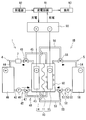
- FIG. 2 is a schematic configuration diagram illustrating a state in which switching is not performed by a switching unit in the redox flow battery of Embodiment 1.
- FIG. 2 is a schematic configuration diagram illustrating a state in which switching is performed by a switching unit in the redox flow battery of Embodiment 1.
- FIG. 9 is a schematic configuration diagram illustrating a state during normal operation in the redox flow battery of Embodiment 2.
- FIG. 9 is a schematic configuration diagram showing a state at the time of dissolving and removing a substance attached to an electrode in the redox flow battery of Embodiment 2. It is a schematic structure figure showing the cell stack used for a redox flow battery.
- a substance that inhibits a battery reaction or a substance that causes a side reaction may adhere to an electrode over time.
- the substance includes, for example, a solid substance such as a precipitate containing element ions contained in the electrolytic solution.
- the substance such as the precipitate adheres to the electrode, the battery performance is reduced or hydrogen gas or the like is generated due to the inhibition of the battery reaction or the occurrence of a side reaction.
- the above-mentioned substance easily adheres to the electrode surface of the negative electrode compared to the positive electrode. Therefore, in the negative electrode, it is easy to cause inhibition of the battery reaction and generation of hydrogen gas. Therefore, it is desired to remove the substance from the electrode.
- Patent Document 1 discloses an RF battery including a filter cell for removing impurities in an electrolytic solution.
- the filter cell has the same structure as the battery cell.
- the filter cell includes a felt having a high filtering function instead of the positive electrode and the negative electrode of the battery cell.
- a pipe connecting the battery cell and the tank is provided separately from the above-described liquid flow path.
- the above-mentioned filter cell is provided in this pipe, and the electrolytic solution flows.
- the filter cell cannot remove the deposits and the like attached to the electrodes.
- the redox flow battery operating method of the present disclosure and the redox flow battery of the present disclosure can easily remove a substance attached to an electrode.
- a method for operating a redox flow battery includes: A battery cell including an electrode used for a positive electrode and an electrode used for a negative electrode, and a method for operating a redox flow battery that operates a redox flow battery including a liquid flow path that circulates an electrolyte for each electrode, In a state where the negative electrode electrolyte is not supplied to the electrode used for the negative electrode, a positive electrode electrolyte is supplied, and a substance attached to the electrode used for the negative electrode is dissolved in the positive electrode electrolyte, Removing ions generated by dissolving the substance by a filter provided in the liquid flow path.
- an RF battery even if a substance such as a precipitate adheres to the surface of an electrode used as a negative electrode (hereinafter, sometimes referred to as an electrode before regeneration), the substance can be easily removed. Can be removed.
- the operation method of the RF battery according to the present disclosure is to supply a positive electrode electrolyte to the pre-regeneration electrode, dissolve and ionize the above-described substance, and use a filter provided in a liquid flow path through which the positive electrode electrolyte flows. It removes ions.
- Such an operation method of the RF battery can easily remove the above substances and is excellent in workability as compared with a case where the battery cell is disassembled and the electrode is washed.
- a positive electrode electrolyte is used as a liquid for dissolving the above substance. That is, an electrolytic solution in which the positive electrode active material causes a battery reaction is used.
- the method for operating an RF battery according to the present disclosure does not require a special cleaning solution or the like for dissolving the above-described substance, and thus is excellent in workability and easy to implement.
- the positive electrode electrolyte has a higher oxidizing power than the negative electrode electrolyte. Therefore, the positive electrode electrolyte can be suitably used for dissolving the substance such as the above-mentioned precipitate.
- the above-described substances are removed in an ion state. Therefore, re-precipitation of the substance can be prevented. Further, the positive electrode electrolyte that has passed through the filter part can be reused as the electrolyte for the RF battery. Therefore, according to the operation method of the RF battery of the present disclosure, the cost required for dissolving and removing the above-described substances can be reduced.
- the redox flow battery includes: A battery cell including an electrode used for a positive electrode and an electrode used for a negative electrode, A liquid flow path through which the electrolyte containing the element ions functioning as the positive electrode active material and the element ions functioning as the negative electrode active material flows through each electrode, A switching unit for mutually switching the polarities of both electrodes, A filter provided in the liquid flow path, The filter unit includes: When the positive electrode electrolyte is supplied to the electrode switched from the negative electrode to the positive electrode by the switching unit, ions generated by dissolving a substance attached to the electrode in the positive electrode electrolyte are removed.
- the RF battery according to the present disclosure can easily remove the above-mentioned substance even if a substance such as a deposit adheres to the surface of the electrode (electrode before regeneration) used as the negative electrode.
- the electrolytic solution used for the RF battery of the present disclosure includes both element ions functioning as a positive electrode active material and element ions functioning as a negative electrode active material.
- Such an electrolyte can be used as a positive electrode electrolyte in which the positive electrode active material performs a battery reaction and a negative electrode electrolyte in which the negative electrode active material performs a battery reaction during a charging operation or a discharging operation. If the charging operation is performed by switching the polarity by the switching unit, the electrolyte used as the negative electrode electrolyte during the normal operation before the switching can be used as the positive electrode electrolyte during the charging operation after the switching.
- this positive electrode electrolyte can be supplied to the pre-regeneration electrode that has become the positive electrode after the switching.
- the positive electrode electrolyte has a higher oxidizing power than the negative electrode electrolyte. Therefore, by supplying the positive electrode electrolyte to the pre-regeneration electrode, the substance adhering to the pre-regeneration electrode can be dissolved and ionized. In addition, ions generated by dissolving the substance can be removed by the filter provided in the liquid flow path of the positive electrode electrolyte.
- Such an RF battery according to the present disclosure can easily remove the above substances and improve workability as compared with a conventional RF battery which requires disassembly and reconstruction of a battery cell to remove the above substances. Excellent.
- the RF battery according to the present disclosure can easily remove the substance as compared with an RF battery that does not include the switching unit and the filter unit that removes the ions. Further, a positive electrode electrolyte is used as a liquid for dissolving the above substances.
- the RF battery according to the present disclosure is excellent in workability because a special cleaning liquid or the like is not required for dissolving the above-described substance. Therefore, the RF battery of the present disclosure can easily perform the operation of dissolving / removing the above substance.
- the above-described substances are removed in an ion state. Therefore, re-precipitation of the substance can be prevented. Further, the positive electrode electrolyte that has passed through the filter part can be reused as the electrolyte for the RF battery. Therefore, the RF battery of the present disclosure can also reduce the cost required for dissolving and removing the above-described substances.
- the RF battery of the present disclosure can be constructed by assembling the above-described conventional RF battery mainly with a switching unit and the above-described filter unit that removes ions. Further, the RF battery of the present disclosure does not require replacement of the electrolytic solution to dissolve and remove the above-described substances. Therefore, it is not necessary to make a significant design change or the like, and it is easy to construct.
- the redox flow battery includes: A battery cell including a positive electrode and a negative electrode, A liquid flow path on the positive electrode side through which a positive electrode electrolyte flows with respect to the positive electrode, A liquid flow path on the negative electrode side through which a negative electrode electrolyte flows with respect to the negative electrode, The liquid flow path on the positive electrode side, A main passage for flowing the positive electrode electrolyte to the positive electrode, A branch for shunting the positive electrode electrolyte to the negative electrode, A switching valve unit for switching between the main road and the branch road, A filter for removing ions generated by dissolving a substance attached to the negative electrode in the positive electrode electrolyte;
- the RF battery according to the present disclosure can easily remove the above substances even if substances such as deposits adhere to the surface of the negative electrode.
- the switching valve unit switches between the main path and the branch path, so that the positive electrode electrolyte can be supplied to the negative electrode.
- the positive electrode electrolyte has a higher oxidizing power than the negative electrode electrolyte. Therefore, by supplying the positive electrode electrolyte to the negative electrode, the substance adhering to the negative electrode can be dissolved and ionized. In addition, ions generated by dissolving the substance can be removed by the filter provided in the liquid flow path on the positive electrode side.
- Such an RF battery according to the present disclosure can easily remove the substance and is excellent in workability, as compared with a conventional RF battery that requires disassembly and reconstruction of a battery cell to remove the substance. .
- the RF battery according to the present disclosure can easily remove the substance as compared with an RF battery that does not have the switching valve unit, the branch path, and the filter unit that removes the ions. Further, a positive electrode electrolyte is used as a liquid for dissolving the above substances.
- the RF battery according to the present disclosure is excellent in workability because a special cleaning solution or the like is not required for dissolving the above-described substance. Therefore, the RF battery of the present disclosure can easily perform the operation of dissolving / removing the above substance.
- the above-described substances are removed in an ion state. Therefore, re-precipitation of the substance can be prevented. Further, the positive electrode electrolyte that has passed through the filter unit can be reused. Therefore, the RF battery of the present disclosure can also reduce the cost required for dissolving and removing the above-described substances.
- the RF battery of the present disclosure does not require a charging operation or the like for dissolving and removing the above-described substances.
- the electrical connection structure can be simplified.
- the filter section is provided downstream of the battery cell in a liquid flow path through which the positive electrode electrolyte flows.
- the above-mentioned ions dissolved in the positive electrode electrolyte can be efficiently removed for the following reasons.
- the positive electrode electrolyte that has passed through the pre-regeneration electrode or the negative electrode flows downstream of the battery cell. This is because the positive electrode electrolyte passed through the pre-regeneration electrode or the negative electrode easily contains a large amount of ions generated by dissolving the above-mentioned substance.
- the RF battery 1 includes an electrode 13 used as a positive electrode (hereinafter, sometimes referred to as a positive electrode 14) and an electrode 13 used as a negative electrode (hereinafter, sometimes referred to as a negative electrode 15). And a liquid flow path 3 through which an electrolytic solution flows through each electrode 13.
- one liquid flow path 3 is used as a liquid flow path 4 on the positive electrode side through which a positive electrode electrolyte flows through the positive electrode 14.
- the other liquid flow path 3 is used as the liquid flow path 5 on the negative electrode side that allows the negative electrode electrolyte to flow through the negative electrode 15.
- the battery cell 10 includes a positive electrode 14 to which a positive electrode electrolyte is supplied, a negative electrode 15 to which a negative electrode electrolyte is supplied, and a diaphragm 11 interposed between the positive electrode 14 and the negative electrode 15.
- the battery cell 10 is constructed using the cell frame 12 illustrated in FIG.
- the RF battery 1 is used as a single cell battery including a single battery cell 10 as shown in FIG. 1 and FIG. 3 described below.
- the RF battery 1 is used as a multi-cell battery including a cell stack 100 in which a plurality of battery cells 10 are stacked as shown in FIG.
- the cell frame 12 includes, for example, a structure including a bipolar plate 120 and a frame 121 as shown in FIG.
- the positive electrode 14 is disposed on one surface of the bipolar plate 120.
- the negative electrode 15 is arranged on the other surface of the bipolar plate 120.
- the frame body 121 is provided on the periphery of the bipolar plate 120.
- One surface of the frame body 121 has a supply path and a discharge path for the positive electrode electrolyte.
- the positive electrode supply path includes a liquid supply hole 4i and a slit extending from the liquid supply hole 4i to the inner peripheral edge of the frame 121.
- the positive electrode discharge path includes a drain hole 4o and a slit extending from the inner peripheral edge to the drain hole 4o.
- the other surface of the frame 121 has a supply path and a discharge path for the negative electrode electrolyte.
- the negative electrode supply path includes a liquid supply hole 5i and a slit extending from the liquid supply hole 5i to the inner peripheral edge.
- the negative electrode discharge path includes a drain hole 5o and a slit extending from the inner peripheral edge to the drain hole 5o.
- the cell stack 100 includes the following stacked body, a pair of end plates 101 sandwiching the stacked body, and a plurality of fastening members 102 for fastening between both end plates 101.
- the laminate is repeatedly laminated in the order of the cell frame 12, the positive electrode 14, the diaphragm 11, and the negative electrode 15.
- the tightening members 102 such as long bolts and nuts
- the stacked state of the stacked body is maintained. Further, by this tightening, the space between the adjacent cell frames 12 is kept liquid-tight.
- a predetermined number of battery cells 10 may be a sub-cell stack 110, and the cell stack 100 may include a plurality of sub-cell stacks 110.
- the liquid flow path 3 includes a tank, a pipe, and a pump as illustrated in FIG.
- the piping connects between the battery cell 10 and the tank.
- the liquid flow path 3 is constructed so as to circulate and supply the electrolytic solution to the battery cells 10 by a pump.
- the liquid flow path 4 on the positive electrode side includes a tank 46 for storing the positive electrode electrolyte, pipes 42 and 44 connecting the battery cell 10 or the cell stack 100 and the tank 46, and a pump 40.
- the pump 40 is provided on an upstream pipe 42 for flowing the positive electrode electrolyte toward the battery cell 10.
- the liquid flow path 5 on the negative electrode side includes a tank 56 for storing the negative electrode electrolyte, pipes 52 and 54 connecting the tank 56 with the battery cell 10 or the cell stack 100, and a pump provided on the pipe 52 on the upstream side. 50.
- the pipe by the above-mentioned liquid supply hole 4i is connected to the pipe.
- the pipe 44 is connected to the pipe by the drain hole 4o.
- the pipe 52 is connected to the pipe by the liquid supply hole 5i.
- the pipe by the above-mentioned drain hole 5o is connected to the pipe 54.
- the electrode 13 may be a porous body such as a fiber aggregate of a carbon material.
- the diaphragm 11 includes an ion exchange membrane and the like.
- the bipolar plate 120 includes a conductive plastic plate containing a conductive material such as graphite and an organic material such as a resin.
- the constituent material of the frame 121 includes a resin such as vinyl chloride, polyethylene, and polypropylene.
- the constituent materials of the pipes 42, 44, 52, 54 include resins such as vinyl chloride.
- the pumps 40 and 50 include an electric pump and the like.
- Elemental ions that function as an active material include metal ions whose valence changes due to redox.
- metal element ions that function as a positive electrode active material include vanadium ions, manganese ions, and iron ions.
- metal element ions that function as a negative electrode active material include vanadium ions, titanium ions, chromium ions, and the like.
- As the positive electrode electrolyte a solution containing an element ion functioning as a positive electrode active material can be used.
- As the negative electrode electrolyte a solution containing an element ion functioning as a negative electrode active material can be used.
- an electrolyte in which the positive electrode electrolyte and the negative electrode electrolyte do not contain ions of a common element type that is, a so-called two-pack type electrolyte
- an electrolyte solution containing ions of element types common to the positive electrode electrolyte solution and the negative electrode electrolyte solution (the valencies may be different) can be used.
- an electrolyte containing both an element ion functioning as a positive electrode active material and an element ion functioning as a negative electrode active material is given.
- a typical example is a so-called one-pack type electrolytic solution.
- the RF battery 1 using the one-component electrolyte has the following effects (1) and (2) as compared with the case of using the two-component electrolyte. (1) It is excellent in productivity of an electrolytic solution. (2) It is easy to correct when a liquid transfer or a valence balance shift occurs.
- Examples of the one-component electrolyte include the following (a) to (c).
- the RF battery 1 is typically connected to a power generation unit 92 and a load 93 via an AC / DC converter 90, a substation facility 91, and the like.
- the RF battery 1 performs charging using the power generation unit 92 as a power supply source. Further, the RF battery 1 performs discharge with the load 93 as a power supply target.
- the terminal portion 62 is connected to one electrode 13. Further, the positive electrode terminal 63 of the AC / DC converter 90 is electrically connected to the one terminal 62 so that the one electrode 13 functions as the positive electrode 14.
- a terminal 66 is connected to the other electrode 13.
- the other electrode 13 functions as the negative electrode 15 by electrically connecting the negative terminal 67 of the AC / DC converter 90 to the other terminal 66.
- an electrolyte is supplied to each electrode 13.
- the battery cell 10 or the cell stack 100 and the AC / DC converter 90 are electrically connected as described above.
- the positive electrode electrolyte stored in the tank 46 is supplied to the positive electrode 14.
- the negative electrode electrolyte stored in the tank 56 is supplied to the negative electrode 15.
- the power generation unit 92 includes, for example, a solar power generator, a wind power generator, and other general power plants.
- the load 93 is, for example, a power system, a customer, or the like.
- the RF battery 1 can be used as a storage battery for power generation of natural energy such as solar power generation and wind power generation, for the purpose of stabilizing fluctuations in power generation output, storing power when excess power is generated, leveling the load, and the like.
- the RF battery 1 is provided in a general power plant, and can be used as a storage battery for the purpose of measures for instantaneous voltage drop, power outage, and load leveling.
- the RF battery 1A of the first embodiment includes a switching unit 6 and a filter unit 7 in addition to the battery cell 10 and the liquid channel 3 described in the above basic configuration.
- the electrolytic solution supplied to each electrode 13 contains an element ion functioning as a positive electrode active material and an element ion functioning as a negative electrode active material.
- the switching unit 6 switches the polarity of each electrode 13 mutually.
- the filter section 7 is provided in the liquid flow path 3.
- the filter unit 7 is provided with the positive electrode electrolyte supplied to the electrode 13 that has been switched from the negative electrode to the positive electrode by the switching unit 6, so that ions 81 generated by dissolving the substance 80 attached to the electrode 13 (FIG. 2) Is removed.
- the substance 80 is schematically shown by a solid circle. 2 and 4, the ions 81 are schematically indicated by broken circles.
- the electrode 13 (pre-reproduction electrode) used as the negative electrode 15 before switching is made to function as the positive electrode 14 after switching (FIG. 2).
- the electrolytic solution in the tank 56 used as the negative electrode tank before the switching is replaced with the positive electrode electrolyte in which the element ions functioning as the positive electrode active material perform the battery reaction after the switching. Let it function as a liquid. Therefore, after the switching, the positive electrode electrolyte can be supplied to the pre-regeneration electrode. Further, the substance 80 attached to the pre-regeneration electrode can be dissolved and ionized by the positive electrode electrolyte. Further, the ions 81 generated by the dissolution can be removed by the filter unit 7.
- each component will be described in detail.
- the switching unit 6 includes, for example, a unit including the following conductive connection units 61 and 65.
- One conductive connection portion 61 electrically connects between a terminal portion 62 connected to one electrode 13 and a positive terminal portion 63 or a negative terminal portion 67 of the AC / DC converter 90.
- the other conductive connection portion 65 electrically connects the terminal portion 66 connected to the other electrode 13 and the terminal portion 63 on the positive electrode side or the terminal portion 67 on the negative electrode side.
- the switching operation of the connection state of the conductive connection portions 61 and 65 may be performed manually, or a configuration may be employed in which a control device (not shown) is provided and the control device automatically performs the switching according to the set conditions.
- the switching unit 6 includes an operation unit such as a knob or a button.
- an operation unit such as a knob or a button.
- Specific examples include a mode including a toggle switch and a mode including a switch and a relay.
- the conductive connection portions 61 and 65 may be formed of a conductor wire or the like. In this case, the connection between the conductive connection portion 61 and the terminal portion 62 and the terminal portions 63 and 67, and the connection between the conductive connection portion 65 and the terminal portion 66 and the terminal portions 63 and 67 may be manually connected.
- a control device it is preferable that the timing of the normal operation and the timing of the dissolving / removing operation of the substance 80 are set in advance and stored in the control device.
- FIG. 1 illustrates a case where the terminal portion 62 on the left side of the drawing is connected to the above-described terminal portion 63 on the positive side by the conductive connecting portion 61, and the electrode 13 on the left side of the drawing functions as the positive electrode 14.
- FIG. 1 exemplifies a case in which the terminal portion 66 on the right side of the drawing and the above-described negative terminal portion 67 are connected by the conductive connection portion 65, and the electrode 13 on the right side of the drawing functions as the negative electrode 15.
- FIG. 2 illustrates a case where the terminal portion 62 on the left side of the drawing and the terminal portion 67 on the negative side are connected by the conductive connecting portion 61, and the electrode 13 on the left side of the drawing functions as the negative electrode 15.
- 2 exemplifies a case where the terminal portion 66 on the right side of the drawing and the terminal portion 63 on the positive side are connected by the conductive connection portion 65, and the electrode 13 on the right side of the drawing functions as the positive electrode 14.
- a filter unit that can remove ions 81 generated by dissolving the substance 80 can be used. It may be appropriately selected according to the type of the ion 81.
- the filter unit 7 may be a filter unit having a functional group that adsorbs ions 81 to a base material made of resin or the like.
- a commercially available ion removal filter can be used for the filter unit 7.
- the filter section 7 is provided at an arbitrary position with respect to the liquid flow path 3 through which the positive electrode electrolyte for dissolving and ionizing the substance 80 flows.
- the positive electrode electrolyte flowing on the downstream side of the battery cell 10 has more ions 81 due to passing through the electrode 13 to which the substance 80 is attached than the liquid flowing on the upstream side of the battery cell 10. Easy to include. Therefore, if the filter 7 is provided downstream of the battery cell 10 in the liquid flow path 3, the filter 7 can efficiently remove the ions 81.
- the filter part 7 can also be provided in the said liquid flow path 3 in the upstream of the battery cell 10.
- the number of filter units 7 in one liquid flow path 3 may be one as in this example, or may be plural.
- Can be The arrangement position of each filter unit 7 can be appropriately selected.
- all of the plurality of filter units 7 may be provided downstream of the battery cells 10 in the liquid flow path 3.
- a part of the plurality of filter units 7 may be provided on the downstream side of the battery cell 10 in the liquid flow path 3, and the other part may be provided on the upstream side of the battery cell 10 in the liquid flow path 3.
- the RF battery 1A of this example includes filter portions 74 and 75 in the pipes 44 and 54 of the liquid flow paths 3 on the downstream side of the battery cell 10, respectively. Therefore, even when any of the two liquid flow paths 3 is used as a flow path for flowing the positive electrode electrolyte for dissolving the substance 80, the ions 81 can be reliably removed by the filter unit 74 or the filter unit 75.
- the filter section 7 may be provided in only one of the two liquid flow paths 3. In this case, only the liquid flow path 3 including the filter unit 7 is used as a flow path for flowing the positive electrode electrolyte for dissolving the substance 80.
- an electrolyte supplied to the electrode 13 functioning as the negative electrode 15 during normal operation and functioning as the positive electrode 14 after the switching of the polarity by the switching unit 6 (hereinafter, referred to as a regeneration electrolyte)
- the regenerating electrolyte functions as a negative electrode electrolyte during normal operation, and may be capable of dissolving the substance 80 when dissolving or removing the substance 80 after switching the polarity.
- Examples of the electrolytic solution that can dissolve the substance 80 include those containing element ions having high oxidizing power. Element ions having high oxidizing power include element ions that function as positive electrode active materials.
- the regeneration electrolyte containing an element ion functioning as a positive electrode active material and an element ion functioning as a negative electrode active material can be suitably used.
- the electrolyte that is supplied to the electrode 13 that functions as the positive electrode 14 during normal operation can function as a positive electrode electrolyte during normal operation, and can function as a negative electrode electrolyte after the above-described polarity switching.
- Examples of such an electrolytic solution include those containing an element ion functioning as a positive electrode active material and an element ion functioning as a negative electrode active material.
- the electrolyte used for the RF battery 1A of the first embodiment the above-mentioned one-pack type electrolyte can be suitably used.
- the RF battery 1A of the first embodiment performs a normal operation, that is, a charging operation or a discharging operation, for example, as follows.
- a terminal 62 connected to one electrode 13 (the left side in FIG. 1) and a terminal 63 on the positive electrode side of the AC / DC converter 90 are electrically connected by a conductive connection 61.
- This electrode 13 is used as a positive electrode 14.
- the liquid flow path 3 on one side (the left side in FIG. 1 on the paper) is a liquid flow path 4 on the positive electrode side.
- a terminal 66 connected to the electrode 13 on the other side (the right side in FIG.
- each of the tanks 46 and 56 provided in each of the liquid flow paths 4 and 5 stores, for example, an electrolytic solution containing an element ion functioning as a positive electrode active material and an element ion functioning as a negative electrode active material.
- the RF battery 1A performs a normal operation by supplying the electrolytic solution to the positive electrode 14 from the tank 46 and supplying the electrolytic solution to the negative electrode 15 from the tank 56.
- element ions as the positive electrode active material in the above-mentioned electrolytic solution perform a battery reaction.
- element ions as the negative electrode active material in the electrolytic solution perform a battery reaction.
- dissolving process A step of supplying a positive electrode electrolyte in a state in which the negative electrode electrolyte is not supplied to the electrode 13 (pre-regeneration electrode) used for the negative electrode, and dissolving the substance 80 attached to the pre-regeneration electrode in the positive electrode electrolyte.
- Removal process A step of removing ions 81 generated by dissolving the substance 80 by the filter unit 7 provided in the liquid flow path 3.
- the following operation is performed when the normal operation is not performed.
- the time when the normal operation is not performed includes a time of standby, a time of repair, and the like.
- (1) The driving of the pumps 40 and 50 of both the liquid flow paths 4 and 5 is stopped, so that the electrolyte is not supplied to both the electrodes 13.
- the switching unit 6 switches the polarity.
- the electrode 13 on the right side of the drawing (electrode before regeneration) is connected to the negative terminal 67 of the AC / DC converter 90 as shown in FIG. Is connected to the terminal portion 63.
- At least charging operation is performed by supplying an electrolytic solution to each electrode 13 from tanks 46 and 56 provided in each liquid flow path 3.
- the electrolyte flowing through the liquid flow path 3 (the liquid flow path 3 on the right side of the paper in FIG. 2) corresponding to the above-mentioned electrode before regeneration is a negative electrode electrolyte in which the negative electrode active material performs a battery reaction.
- the electrolyte flowing through the liquid flow path 3 on the right side of the drawing is the negative electrode electrolyte.
- the electrolyte flowing through the liquid flow path 3 on the right side of the drawing functions as a positive electrode electrolyte in which the positive electrode active material performs a battery reaction. Furthermore, the element operation as the positive electrode active material is charged by the charging operation, and functions as a positive electrode electrolyte having high oxidizing power. Therefore, during the charging operation, the positive electrode electrolyte having high oxidizing power is supplied to the pre-regeneration electrode, and the substance 80 attached to the pre-regeneration electrode can be dissolved and ionized in the positive electrode electrolyte.
- the positive electrode electrolyte passed through the pre-regeneration electrode may include ions 81 generated by dissolving the substance 80.
- the positive electrode electrolyte which may include the ions 81, flows through the liquid flow path 3 including the filter section 75, so that the ions 81 can be removed by the filter section 75. By removing the ions 81 with the filter unit 75, re-precipitation of the substance 80 can be prevented.
- the electrolyte that flows through the liquid flow path 3 on the left side of the paper and functions as a positive electrode electrolyte before the polarity is switched functions as a negative electrode electrolyte by the charging operation after the polarity is switched.
- the negative electrode electrolyte before the switching is performed by the charging operation after the switching.
- the oxidizing power can be gradually increased by the charging operation.
- a typical example of such an electrolyte is an all-vanadium-based electrolyte.
- Charging conditions for dissolving / removing the substance 80 can be appropriately set within a range in which the substance 80 can be dissolved.
- SOC state of charge
- charging operation may be performed until the SOC of the positive electrode electrolyte becomes 50% or more.
- the charging operation may be performed until the SOC of the positive electrode electrolyte becomes 60% or more, and further 70% or more.
- the SOC may be appropriately measured using a known method or device.
- the RF battery 1A is used for normal operation.
- the normal operation may be performed, for example, without changing the connection state of the terminal portions 62 and 66 while the dissolving and removing operation of the substance 80 is performed.
- the electrode 13 on the left side of the drawing is used as a negative electrode 15, and the electrolyte flowing through the liquid flow path 3 on the left side of the drawing is made to function as a negative electrode electrolyte.
- the electrode 13 on the right side of the drawing is used as the positive electrode 14, and the electrolyte flowing through the liquid flow path 3 on the right side of the drawing is made to function as the positive electrode electrolyte.
- the substance 80 may adhere to the electrode 13 (the electrode before regeneration) on the left side of the drawing as the negative electrode 15 with time.
- the polarity is switched by the switching unit 6 and the connection state of the terminal units 62 and 66 is changed to the state shown in FIG. It is preferable to perform a charging operation or the like.
- the positive electrode electrolyte passing through the pre-regeneration electrode on the left side of the drawing may include ions 81 generated by dissolving the substance 80.
- the positive electrode electrolyte which may include the ions 81, flows through the liquid flow path 3 on the left side of the drawing including the filter part 74, so that the ions 81 can be removed by the filter part 74. By removing the ions 81 by the filter unit 74, re-precipitation of the substance 80 can be prevented.
- the RF battery 1 of this example includes the filter portions 74 and 75 in the two liquid flow paths 3 respectively. Therefore, regardless of which of the two electrodes 13 is used as the negative electrode 15 for normal operation, the substance 80 attached to the electrode 13 used as the negative electrode can be removed as ions 81 by the filter unit 7. This is because if the charging operation is performed while the polarity is changed as described above, the substance 80 attached to the electrode 13 used for the negative electrode can be dissolved and ionized in the positive electrode electrolyte.
- the normal operation may be performed, for example, after the polarity is switched by the switching unit 6 from the state at the time of the work of dissolving and removing the substance 80 and the connection state of the terminal units 62 and 66 is returned to the original state.
- the connection state shown in FIG. 2 is returned to the connection state shown in FIG. That is, the electrode 13 on the left side of the drawing is the positive electrode 14, and the electrode 13 on the right side of the drawing is the negative electrode 15.
- the substance 80 can adhere to the electrode 13 on the right side of the paper used for the negative electrode over time. Therefore, it is preferable to provide the filter unit 75 only in the liquid flow path 3 on the right side of the drawing corresponding to the electrode 13 on the right side of the drawing.
- the filter section 7 may be omitted from the liquid flow path 3 on the left side of the drawing.
- the RF battery 1A according to the first embodiment includes a switching unit 6 and a filter unit 7. Therefore, even if the substance 80 such as a precipitate adheres to the surface of the electrode 13 (electrode before regeneration) used as the negative electrode 15, the substance 80 is dissolved by switching the polarity by the switching unit 6 and performing a charging operation or the like. Then, the ions 81 can be removed by the filter unit 7.
- the RF battery 1A of the first embodiment can easily remove the substance 80 from the following points. (1) Disassembly / reconstruction of the battery cell 10 is not required to remove the substance 80. (2) No special liquid is required for dissolving the substance 80. (3) No need to replace the electrolyte.
- the substance 80 is removed not in a solid state such as the substance 80 but in the state of the ions 81, so that re-precipitation of the substance 80 can be prevented.
- the electrolyte used to dissolve the substance 80 can be reused. Therefore, the RF battery 1A can also reduce the cost required for dissolving and removing the substance 80.
- the RF battery 1A of the first embodiment can be constructed by mainly attaching the switching unit 6 and the filter unit 7 to the above-described basic configuration. Therefore, a significant design change is not required, and construction is easy.
- the method of operating the RF battery according to the embodiment is performed on the RF battery 1A according to the first embodiment, so that the substance 80 can be ionized and easily removed as described above.
- the RF battery 1B of the second embodiment includes the battery cell 10 described in the above basic configuration, the liquid flow path 4 on the positive electrode side, and the liquid flow path 5 on the negative electrode side.
- the RF battery 1B includes a filter section 7 while the liquid flow path 4 on the positive electrode side is branched.
- the liquid flow path 4 on the positive electrode side includes a main trunk path 4T, a branch path 4B, and switching valve parts 47 and 48.
- the main trunk path 4 ⁇ / b> T circulates a positive electrode electrolyte with respect to the positive electrode 14.
- the branch path 4B shunts the positive electrode electrolyte to the negative electrode 15.
- the switching valve portions 47 and 48 switch between the main road 4T and the branch road 4B.
- the liquid flow path 4 on the positive electrode side includes a filter unit 7.
- the filter unit 7 removes ions 81 (FIG. 4) generated by dissolving the substance 80 attached to the negative electrode 15 in the positive electrode electrolyte.
- the switching valve portions 47 and 48 are switched so that the main trunk 4T can be used, and the positive electrode electrolyte is supplied to the positive electrode 14.
- the positive electrode electrolyte can be supplied to the negative electrode 15.
- the substance 80 attached to the negative electrode 15 can be dissolved and ionized by the positive electrode electrolyte.
- the ions 81 generated by the dissolution can be removed by the filter unit 7.
- the main path 4T of this example is substantially the same as the liquid flow path 3 having the above-described basic configuration.
- the main road 4T includes an upstream pipe 42 and a downstream pipe 44.
- the upstream pipe 42 allows the cathode electrolyte to flow from the tank 46 toward the battery cell 10.
- the downstream pipe 44 returns the positive electrode electrolyte from the battery cell 10 to the tank 46.
- the branch path 4B of the present example includes an upstream pipe 43 and a downstream pipe 45.
- the upstream pipe 43 is connected to the upstream pipe 42 and the battery cell 10.
- the downstream pipe 45 is connected to the battery cell 10 and the downstream pipe 44.
- the switching valve portion 47 is provided so as to be able to switch between the upstream pipes 42 and 43.
- the switching valve portion 47 is disposed downstream of the pump 40 provided in the upstream pipe 42. That is, in this example, one pump 40 is shared by the main trunk path 4T and the branch path 4B. In addition, a pump may be provided in each of the main trunk path 4T and the branch path 4B. This point is the same for a main road 5T and a branch road 5B to be described later.
- the switching valve portion 48 is provided so as to be able to switch between the downstream pipes 44 and 45.
- a resin such as vinyl chloride is used as in the pipes 42 and 44.
- the switching valve portions 47 and 48 include, for example, a three-way valve and the like.
- a filter unit that can remove ions 81 generated by dissolving the substance 80 can be appropriately used as the filter unit 7.
- the details of the filter unit 7 may be referred to in the first embodiment.
- the filter unit 7 is provided at an arbitrary position with respect to the liquid flow path 4 on the positive electrode side. As in this example, it is preferable to provide the filter section 7 on the downstream side of the battery cell 10 in the liquid flow path 4 on the positive electrode side. As described in the first embodiment, the positive electrode electrolyte flowing downstream of the battery cell 10 in the liquid flow path 4 contains a large amount of ions 81 generated by dissolving the substance 80. Therefore, the filter unit 7 provided on the downstream side of the battery cell 10 can efficiently remove the ions 81.
- the filter section 7 of the present example is provided downstream of the switching valve section 48 in the downstream pipe 44 forming the main trunk path 4T.
- the filter section 7 may be provided in the downstream pipe 45 forming the branch path 4B.
- the filter unit 7 may be provided on the liquid flow path 4 on the positive electrode side on the upstream side of the battery cell 10.
- the filter section 7 may be provided on the upstream pipe 42 forming the main trunk path 4T on the upstream side of the switching valve section 47 or on the upstream pipe 43 forming the branch path 4B.
- the liquid flow path 5 on the negative electrode side similarly to the liquid flow path 4 on the positive electrode side, the liquid flow path 5 on the negative electrode side also includes a main trunk path 5T, a branch path 5B, and switching valve portions 57 and 58. Therefore, the negative electrode electrolyte can be supplied to the positive electrode 14. However, the liquid flow path 5 on the negative electrode side does not include the filter unit 7.
- the main trunk path 5T of this example is substantially the same as the liquid flow path 3 having the above-described basic configuration.
- the main road 5T includes an upstream pipe 52 and a downstream pipe 54.
- the upstream pipe 52 allows the negative electrode electrolyte to flow from the tank 56 toward the battery cell 10.
- the downstream pipe 54 returns the negative electrode electrolyte from the battery cell 10 to the tank 56.
- the branch path 5B of this example includes an upstream pipe 53 and a downstream pipe 55.
- the upstream pipe 53 is connected to the upstream pipe 52 and the battery cell 10.
- the downstream pipe 55 is connected to the battery cell 10 and the downstream pipe 54.
- the switching valve portion 57 is provided so as to be able to switch between the upstream pipes 52 and 53. Further, the switching valve portion 57 is disposed downstream of the pump 50 provided in the upstream pipe 52.
- the switching valve section 58 is provided so as to be able to switch between the downstream pipes 54 and 55.
- examples of the cathode electrolyte include those containing element ions functioning as a cathode active material.
- examples of the negative electrode electrolyte include those containing an element functioning as a negative electrode active material.
- the above-described two-component electrolyte can be used.
- the branch passages 4B and 5B are used, the negative electrode electrolyte is supplied to the positive electrode 14 and the positive electrode electrolyte is supplied to the negative electrode 15.
- the electrolyte of each electrode remaining in the battery cell 10 and the electrolyte of each electrode newly supplied are mixed to function as an active material of each electrode. It is allowed to contain element ions.
- examples of the electrolytic solution used for the RF battery 1B of Embodiment 2 include those containing an element ion functioning as a positive electrode active material and an element ion functioning as a negative electrode active material.
- the above-mentioned one-component electrolyte can be used.
- problems caused by the above-described mixing such as a decrease in the active material of each electrode, do not substantially occur.
- the RF battery 1B of the second embodiment performs a normal operation, for example, a charging operation or a discharging operation as follows.
- the switching valve portions 47, 48, 57, 58 are switched so that the main trunk roads 4T, 5T can be used.
- the positive electrode electrolyte is supplied to the positive electrode 14 (the electrode on the left side in FIG. 3) using the main trunk path 4T of the liquid flow path 4 on the positive electrode side (see black arrows).
- a negative electrode electrolyte is supplied to the negative electrode 15 (the right electrode in FIG. 3) using the main trunk path 5T of the liquid flow path 5 on the negative electrode side (see black arrows).
- the method of operating the RF battery according to the above-described embodiment is performed to remove the substance 80. More specifically, the following operation is performed when normal operation such as standby or repair is not performed.
- the positive electrode electrolyte is supplied to the negative electrode 15 from the tank 46 provided in the liquid flow path 4 on the positive electrode side.
- a negative electrode electrolyte is supplied to the positive electrode 14 from a tank 56 provided in the liquid flow path 5 on the negative electrode side.
- the positive electrode electrolyte is supplied from the tank 46 to the negative electrode 15 through the pipe 42 of the main trunk path 4T and the pipe 43 of the branch path 4B (see a black broken arrow).
- the positive electrode electrolyte passed through the negative electrode 15 returns to the tank 46 via the pipe 45 of the branch path 4B and the pipe 44 of the main trunk path 4T.
- the negative electrode electrolyte is supplied to the positive electrode 14 via the pipes 52 and 53, and returns to the tank 56 via the pipes 55 and 54 (see white broken arrows).
- the positive electrode electrolyte has a high oxidizing power. Therefore, when the positive electrode electrolyte is supplied to the negative electrode 15, the substance 80 attached to the negative electrode 15 can be dissolved in the positive electrode electrolyte.
- the positive electrode electrolyte passed through the negative electrode 15 may include ions 81 generated by dissolving the substance 80.
- the positive electrode electrolyte which may include the ions 81 flows through the liquid flow path 4 on the positive electrode side including the filter unit 7, whereby the ions 81 can be removed by the filter unit 7. By removing the ions 81 by the filter unit 7, re-precipitation of the substance 80 can be prevented.
- the conditions such as the time for supplying the positive electrode electrolyte to the negative electrode 15 for dissolving and removing the substance 80 can be appropriately set within a range where the substance 80 can be dissolved.
- the SOC of the positive electrode electrolyte is 60% or more, and more preferably 70% or more, the liquid supply time can be further shortened.
- the positive electrode electrolyte after the charging operation usually has a high SOC (for example, 50% or more). Therefore, the positive electrode electrolyte after the charging operation can be suitably used as a solution for dissolving and removing the substance 80.
- the RF battery 1B is used for normal operation. Specifically, the driving of the pumps 40 and 50 is stopped. Then, in a state where the electrolyte is not supplied to the positive electrode 14 and the negative electrode 15, the switching valve portions 47, 48, 57, 58 are switched so that the main trunks 4T, 5T can be used. That is, the state shown in FIG. 4 is returned to the state where the positive electrode electrolyte is supplied to the positive electrode 14 and the negative electrode electrolyte is supplied to the negative electrode 15 as shown in FIG.
- the valence balance may be appropriately adjusted after the substance 80 is dissolved and removed.
- the RF battery 1B of the second embodiment includes the branch passage 4B, the switching valves 47 and 48, and the filter 7 in the liquid flow path 4 on the positive electrode side. Therefore, even if the substance 80 such as a deposit adheres to the surface of the negative electrode 15, the positive electrode electrolyte can be supplied to the negative electrode 15 by switching from the main trunk path 4 ⁇ / b> T to the branch path 4 ⁇ / b> B by the switching valve parts 47 and 48.
- the substance 80 can be dissolved in the positive electrode electrolyte and removed as ions 81 by the filter unit 7.
- the RF battery 1B of the second embodiment can easily remove the substance 80 from the following points. (1) Disassembly / reconstruction of the battery cell 10 is not required to remove the substance 80. (2) No special liquid is required for dissolving the substance 80.
- the substance 80 is removed in the state of the ions 81, re-precipitation of the substance 80 can be prevented.
- the electrolyte used for dissolving the substance 80 can be reused. Therefore, the cost required for dissolving and removing the substance 80 can be reduced in the RF battery 1B.
- the RF battery 1B of the second embodiment does not require a charging operation or the like for dissolving and removing the substance 80. Therefore, the electrical connection structure can be simplified.
- the method of operating the RF battery according to the embodiment is performed on the RF battery 1B according to the second embodiment, so that the substance 80 can be ionized and easily removed as described above.
- the branch channel 4B can be used in the liquid channel 4 on the positive electrode side
- the branch channel 5B can be used in the liquid channel 5 on the negative electrode side.
- the polarity is switched by the switching unit 6 to perform the charging operation and the like.
- Such an RF battery can quickly supply a positive electrode electrolyte to the electrode 13 used as the negative electrode 15. Further, since the electrode 13 functions as the positive electrode 14, the SOC of the positive electrode electrolyte is not easily reduced due to the dissolution of the substance 80.
- this RF battery can supply the positive electrode electrolyte having a high oxidizing power to the electrode 13 to which the substance 80 can adhere, from the beginning to the end of the dissolving and removing operation of the substance 80.
- Such an RF battery can more reliably dissolve the substance 80. Further, it is expected that the work time required for dissolving and removing the substance 80 can be reduced.
- the liquid flow path 5 on the negative electrode side is only the main trunk path 5T, and the branch path 5B and the switching valve portions 57 and 58 are omitted.
- the stored amount of the electrolyte in the tanks 46 and 56 may be shifted. Therefore, after the dissolution / removal operation of the substance 80 is completed, it is preferable to correct the deviation of the stored amount.
- a pipe (not shown) for communicating the two tanks 46 and 56 is provided. By opening this pipe, the deviation of the stored amount can be easily corrected.
Landscapes
- Life Sciences & Earth Sciences (AREA)
- Engineering & Computer Science (AREA)
- Manufacturing & Machinery (AREA)
- Sustainable Development (AREA)
- Sustainable Energy (AREA)
- Chemical & Material Sciences (AREA)
- Chemical Kinetics & Catalysis (AREA)
- Electrochemistry (AREA)
- General Chemical & Material Sciences (AREA)
- Fuel Cell (AREA)
Abstract
正極に用いられる電極と負極に用いられる電極とを備える電池セルと、各電極に対して電解液を流通する液流路とを備えるレドックスフロー電池を運転するレドックスフロー電池の運転方法であって、負極に用いられた前記電極に負極電解液が供給されていない状態で、正極電解液を供給して、前記負極に用いられた電極に付着する物質を前記正極電解液に溶解する工程と、前記物質が溶解して生じたイオンを前記液流路に設けられたフィルタ部で除去する工程とを備えるレドックスフロー電池の運転方法。
Description
本開示は、レドックスフロー電池の運転方法、及びレドックスフロー電池に関する。
蓄電池の一つに、電極に電解液を供給して電池反応を行うレドックスフロー電池(以下、RF電池と呼ぶことがある)がある。RF電池は、代表的には、特許文献1に記載されるように電池セルと、電池セルに対して電解液を流通する液流路とを備える。電池セルは、正極電解液が供給される正極電極と、負極電解液が供給される負極電極と、両電極間に介在される隔膜とを備える。液流路は、電解液を貯留するタンクと、電池セルとタンクとの間を繋ぐ配管とを備える。通常、RF電池は、正極電解液を流通する液流路と、負極電解液を流通する液流路とをそれぞれ備える。
本開示のレドックスフロー電池の運転方法は、
正極に用いられる電極と負極に用いられる電極とを備える電池セルと、各電極に対して電解液を流通する液流路とを備えるレドックスフロー電池を運転するレドックスフロー電池の運転方法であって、
負極に用いられた前記電極に負極電解液が供給されていない状態で、正極電解液を供給して、前記負極に用いられた電極に付着する物質を前記正極電解液に溶解する工程と、
前記物質が溶解して生じたイオンを前記液流路に設けられたフィルタ部で除去する工程とを備える。
正極に用いられる電極と負極に用いられる電極とを備える電池セルと、各電極に対して電解液を流通する液流路とを備えるレドックスフロー電池を運転するレドックスフロー電池の運転方法であって、
負極に用いられた前記電極に負極電解液が供給されていない状態で、正極電解液を供給して、前記負極に用いられた電極に付着する物質を前記正極電解液に溶解する工程と、
前記物質が溶解して生じたイオンを前記液流路に設けられたフィルタ部で除去する工程とを備える。
本開示のレドックスフロー電池は、
正極に用いられる電極と負極に用いられる電極とを備える電池セルと、
正極活物質として機能する元素イオンと、負極活物質として機能する元素イオンとを含む電解液を各電極に流通する液流路と、
両電極の極性を相互に切り替える切替部と、
前記液流路に設けられたフィルタ部とを備え、
前記フィルタ部は、
前記切替部によって負極から正極に切り替えられた前記電極に正極電解液が供給されることで、前記電極に付着する物質が前記正極電解液に溶解して生じたイオンを除去する。
正極に用いられる電極と負極に用いられる電極とを備える電池セルと、
正極活物質として機能する元素イオンと、負極活物質として機能する元素イオンとを含む電解液を各電極に流通する液流路と、
両電極の極性を相互に切り替える切替部と、
前記液流路に設けられたフィルタ部とを備え、
前記フィルタ部は、
前記切替部によって負極から正極に切り替えられた前記電極に正極電解液が供給されることで、前記電極に付着する物質が前記正極電解液に溶解して生じたイオンを除去する。
別の本開示のレドックスフロー電池は、
正極電極及び負極電極を備える電池セルと、
前記正極電極に対して正極電解液を流通する正極側の液流路と、
前記負極電極に対して負極電解液を流通する負極側の液流路とを備え、
前記正極側の液流路は、
前記正極電極に対して前記正極電解液を流通する主幹路と、
前記負極電極に対して前記正極電解液を分流する分岐路と、
前記主幹路と前記分岐路とを切り替える切替弁部と、
前記負極電極に付着する物質が前記正極電解液に溶解して生じたイオンを除去するフィルタ部とを備える。
正極電極及び負極電極を備える電池セルと、
前記正極電極に対して正極電解液を流通する正極側の液流路と、
前記負極電極に対して負極電解液を流通する負極側の液流路とを備え、
前記正極側の液流路は、
前記正極電極に対して前記正極電解液を流通する主幹路と、
前記負極電極に対して前記正極電解液を分流する分岐路と、
前記主幹路と前記分岐路とを切り替える切替弁部と、
前記負極電極に付着する物質が前記正極電解液に溶解して生じたイオンを除去するフィルタ部とを備える。
[本開示が解決しようとする課題]
レドックスフロー電池(RF電池)では、経時的に、電池反応を阻害する物質や副反応を引き起こす物質が電極に付着することがある。上記物質は、例えば、電解液中に含まれる元素イオンを含む析出物といった固体物が挙げられる。上記析出物等の物質が電極に付着することで、電池反応の阻害や副反応の発生により、電池性能が低下したり、水素ガス等が発生したりする。特に、負極電極では、正極電極に比較して、電極表面に上記物質が付着し易い。そのため、負極電極では、電池反応の阻害や水素ガスの発生等を招き易い。従って、電極から上記物質を除去することが望まれる。
レドックスフロー電池(RF電池)では、経時的に、電池反応を阻害する物質や副反応を引き起こす物質が電極に付着することがある。上記物質は、例えば、電解液中に含まれる元素イオンを含む析出物といった固体物が挙げられる。上記析出物等の物質が電極に付着することで、電池反応の阻害や副反応の発生により、電池性能が低下したり、水素ガス等が発生したりする。特に、負極電極では、正極電極に比較して、電極表面に上記物質が付着し易い。そのため、負極電極では、電池反応の阻害や水素ガスの発生等を招き易い。従って、電極から上記物質を除去することが望まれる。
例えば、電池セルを解体して電極を洗浄すれば、電極に付着した上記析出物等の物質を除去できる。しかし、電池セルの解体及び再構築が必要であり、作業性に劣る。そのため、電極、特に負極電極に付着した上記析出物等の物質を容易に除去できるRF電池が望まれる。
特許文献1では、電解液中の不純物を除去するフィルタ用セルを備えるRF電池を開示する。上記フィルタ用セルは、電池セルと同様な構造を有する。但し、上記フィルタ用セルは、電池セルの正極電極及び負極電極に代えて、濾過機能が高いフェルトを備える。特許文献1のRF電池では、上述の液流路とは別に電池セルとタンクとを繋ぐ配管を設ける。この配管に上記フィルタ用セルを設けて電解液を流す。このようにして、特許文献1のRF電池は、電解液中に浮遊する不純物を上記フィルタ用セルによって除去する。しかし、上記フィルタ用セルでは、電極に付着した上記析出物等を除去できない。
本開示は、電極に付着した物質を容易に除去できるレドックスフロー電池の運転方法を提供することを目的の一つとする。また、本開示は、電極に付着した物質を容易に除去できるレドックスフロー電池を提供することを別の目的の一つとする。
[本開示の効果]
本開示のレドックスフロー電池の運転方法、及び本開示のレドックスフロー電池は、電極に付着した物質を容易に除去できる。
本開示のレドックスフロー電池の運転方法、及び本開示のレドックスフロー電池は、電極に付着した物質を容易に除去できる。
[本開示の実施形態の説明]
最初に本開示の実施態様を列記して説明する。
(1)本開示の一態様に係るレドックスフロー電池の運転方法は、
正極に用いられる電極と負極に用いられる電極とを備える電池セルと、各電極に対して電解液を流通する液流路とを備えるレドックスフロー電池を運転するレドックスフロー電池の運転方法であって、
負極に用いられた前記電極に負極電解液が供給されていない状態で、正極電解液を供給して、前記負極に用いられた電極に付着する物質を前記正極電解液に溶解する工程と、
前記物質が溶解して生じたイオンを前記液流路に設けられたフィルタ部で除去する工程とを備える。
最初に本開示の実施態様を列記して説明する。
(1)本開示の一態様に係るレドックスフロー電池の運転方法は、
正極に用いられる電極と負極に用いられる電極とを備える電池セルと、各電極に対して電解液を流通する液流路とを備えるレドックスフロー電池を運転するレドックスフロー電池の運転方法であって、
負極に用いられた前記電極に負極電解液が供給されていない状態で、正極電解液を供給して、前記負極に用いられた電極に付着する物質を前記正極電解液に溶解する工程と、
前記物質が溶解して生じたイオンを前記液流路に設けられたフィルタ部で除去する工程とを備える。
本開示のRF電池の運転方法によれば、負極電極として用いられた電極(以下、再生前電極と呼ぶことがある)の表面に析出物等の物質が付着していても、上記物質を容易に除去できる。
詳しくは、本開示のRF電池の運転方法は、再生前電極に正極電解液を供給して上記物質を溶解してイオン化し、この正極電解液を流通する液流路に設けられたフィルタ部によってイオンを除去する、というものである。このようなRF電池の運転方法は、電池セルを解体して電極を洗浄する場合に比較して、上記物質の除去を容易に行えて作業性に優れる。また、上記物質を溶解する液体として正極電解液を用いる。即ち正極活物質が電池反応を行う電解液を用いる。本開示のRF電池の運転方法では、上記物質の溶解のために特別な洗浄液等が不要であることからも、作業性に優れて実施し易い。なお、正極電解液は、負極電解液に比較して高い酸化力を有する。そのため、正極電解液は、上述の析出物等の物質の溶解に好適に利用できる。
また、本開示のRF電池の運転方法では、上述の物質をイオンの状態で除去する。そのため、上記物質の再析出も防止できる。更に、フィルタ部を透過した正極電解液をRF電池の電解液として再利用できる。そのため、本開示のRF電池の運転方法によれば、上述の物質の溶解・除去に必要なコストも低減できる。
(2)本開示の一態様に係るレドックスフロー電池は、
正極に用いられる電極と負極に用いられる電極とを備える電池セルと、
正極活物質として機能する元素イオンと、負極活物質として機能する元素イオンとを含む電解液を各電極に流通する液流路と、
両電極の極性を相互に切り替える切替部と、
前記液流路に設けられたフィルタ部とを備え、
前記フィルタ部は、
前記切替部によって負極から正極に切り替えられた前記電極に正極電解液が供給されることで、前記電極に付着する物質が前記正極電解液に溶解して生じたイオンを除去する。
正極に用いられる電極と負極に用いられる電極とを備える電池セルと、
正極活物質として機能する元素イオンと、負極活物質として機能する元素イオンとを含む電解液を各電極に流通する液流路と、
両電極の極性を相互に切り替える切替部と、
前記液流路に設けられたフィルタ部とを備え、
前記フィルタ部は、
前記切替部によって負極から正極に切り替えられた前記電極に正極電解液が供給されることで、前記電極に付着する物質が前記正極電解液に溶解して生じたイオンを除去する。
本開示のRF電池は、負極電極として用いられた電極(再生前電極)の表面に析出物等の物質が付着していても、上記物質を容易に除去できる。
詳しくは、本開示のRF電池に用いる電解液は、正極活物質として機能する元素イオン及び負極活物質として機能する元素イオンの双方を含む。このような電解液は、充電運転時や放電運転時に、正極活物質が電池反応を行う正極電解液にも、負極活物質が電池反応を行う負極電解液にも利用できる。切替部によって極性を切り替えて充電運転等を行えば、切替前の通常運転時には負極電解液として用いた電解液を、切替後の充電運転時には正極電解液として使用できる。また、この正極電解液を、切替後に正極となった再生前電極に供給できる。正極電解液は負極電解液よりも高い酸化力を有する。そのため、再生前電極に正極電解液を供給することで、再生前電極に付着する上記物質を溶解して、イオン化できる。また、上記正極電解液の液流路に備えられるフィルタ部によって、上記物質が溶解して生じたイオンを除去できる。このような本開示のRF電池は、上述の物質を除去するために電池セルの解体・再構築が必要である従来のRF電池に比較して、上記物質の除去を容易に行えて作業性に優れる。即ち、本開示のRF電池は、切替部及び上記イオンを除去するフィルタ部を有していないRF電池に比較して、上記物質の除去を容易に行える。更に、上記物質を溶解する液体として正極電解液を用いる。本開示のRF電池では、上記物質の溶解のために特別な洗浄液等が不要であることからも、作業性に優れる。従って、本開示のRF電池は、上記物質の溶解・除去作業を実施し易い。
また、本開示のRF電池では、上述の物質をイオンの状態で除去する。そのため、上記物質の再析出も防止できる。更に、フィルタ部を透過した正極電解液をRF電池の電解液として再利用できる。そのため、本開示のRF電池は、上述の物質の溶解・除去に必要なコストも低減できる。
加えて、本開示のRF電池は、上述の従来のRF電池に対して、主として、切替部と上述のイオンを除去するフィルタ部とを組み付けることで構築できる。また、本開示のRF電池は、上述の物質の溶解・除去を行うために電解液の入替が不要である。従って、大幅な設計変更等が不要であり、構築し易い。
(3)本開示の別の態様に係るレドックスフロー電池は、
正極電極及び負極電極を備える電池セルと、
前記正極電極に対して正極電解液を流通する正極側の液流路と、
前記負極電極に対して負極電解液を流通する負極側の液流路とを備え、
前記正極側の液流路は、
前記正極電極に対して前記正極電解液を流通する主幹路と、
前記負極電極に対して前記正極電解液を分流する分岐路と、
前記主幹路と前記分岐路とを切り替える切替弁部と、
前記負極電極に付着する物質が前記正極電解液に溶解して生じたイオンを除去するフィルタ部とを備える。
正極電極及び負極電極を備える電池セルと、
前記正極電極に対して正極電解液を流通する正極側の液流路と、
前記負極電極に対して負極電解液を流通する負極側の液流路とを備え、
前記正極側の液流路は、
前記正極電極に対して前記正極電解液を流通する主幹路と、
前記負極電極に対して前記正極電解液を分流する分岐路と、
前記主幹路と前記分岐路とを切り替える切替弁部と、
前記負極電極に付着する物質が前記正極電解液に溶解して生じたイオンを除去するフィルタ部とを備える。
本開示のRF電池は、負極電極の表面に析出物等の物質が付着していても、上記物質を容易に除去できる。
詳しくは、本開示のRF電池では、切替弁部によって主幹路と分岐路とを切り替えることで、負極電極に正極電解液を供給できる。正極電解液は負極電解液よりも高い酸化力を有する。そのため、負極電極に正極電解液を供給することで、負極電極に付着する上記物質を溶解して、イオン化できる。また、正極側の液流路に備えられるフィルタ部によって、上記物質が溶解して生じたイオンを除去できる。このような本開示のRF電池は、上記物質を除去するために電池セルの解体・再構築が必要である従来のRF電池に比較して、上記物質の除去を容易に行えて作業性に優れる。即ち、本開示のRF電池は、切替弁部及び分岐路並びに上記イオンを除去するフィルタ部を有していないRF電池に比較して、上記物質の除去を容易に行える。更に、上記物質を溶解する液体として正極電解液を用いる。本開示のRF電池は、上記物質の溶解のために特別な洗浄液等が不要であることからも、作業性に優れる。従って、本開示のRF電池は、上記物質の溶解・除去作業を実施し易い。
また、本開示のRF電池では、上述の物質をイオンの状態で除去する。そのため、上記物質の再析出も防止できる。更に、フィルタ部を透過した正極電解液を再利用できる。そのため、本開示のRF電池は、上述の物質の溶解・除去に必要なコストも低減できる。
更に、本開示のRF電池は、上述の物質の溶解・除去のために充電運転等が不要である。その結果、電気的な接続構造を簡素にできる。
(4)本開示のレドックスフロー電池の一例として、
前記フィルタ部は、前記正極電解液を流通する液流路における前記電池セルの下流側に設けられる形態が挙げられる。
前記フィルタ部は、前記正極電解液を流通する液流路における前記電池セルの下流側に設けられる形態が挙げられる。
上記形態は、以下の理由により、正極電解液に溶解した上述のイオンを効率よく除去できる。上記形態における正極電解液を流通する液流路のうち、電池セルの下流側には、再生前電極又は負極電極を経た正極電解液が流れる。再生前電極又は負極電極を経た正極電解液中には上記物質が溶解して生じたイオンを多く含み易いからである。
[本開示の実施形態の詳細]
以下に図面を参照して、本開示の実施形態を具体的に説明する。図において同一符号は同一名称物を意味する。
以下に図面を参照して、本開示の実施形態を具体的に説明する。図において同一符号は同一名称物を意味する。
[実施形態]
(RF電池の基本構成)
まず、主に図1,図5を参照して、実施形態のレドックスフロー電池(RF電池)1の基本構成及び基本的な使用状態を説明する。
(RF電池の基本構成)
まず、主に図1,図5を参照して、実施形態のレドックスフロー電池(RF電池)1の基本構成及び基本的な使用状態を説明する。
RF電池1は、図1に示すように、正極に用いられる電極13(以下、正極電極14と呼ぶことがある)と負極に用いられる電極13(以下、負極電極15と呼ぶことがある)とを備える電池セル10と、各電極13に対して電解液を流通する液流路3とを備える。代表的には、一方の液流路3は、正極電極14に対して正極電解液を流通する正極側の液流路4に利用される。他方の液流路3は、負極電極15に対して負極電解液を流通する負極側の液流路5に利用される。
〈電池セル〉
電池セル10は、正極電解液が供給される正極電極14と、負極電解液が供給される負極電極15と、正極電極14,負極電極15間に介在される隔膜11とを備える。代表的には、電池セル10は、図5に例示されるセルフレーム12を用いて構築される。RF電池1は、図1や後述する図3に示すような単一の電池セル10を備える単セル電池として利用される。又は、RF電池1は、図5に示すような複数の電池セル10を積層したセルスタック100を備える多セル電池として利用される。
電池セル10は、正極電解液が供給される正極電極14と、負極電解液が供給される負極電極15と、正極電極14,負極電極15間に介在される隔膜11とを備える。代表的には、電池セル10は、図5に例示されるセルフレーム12を用いて構築される。RF電池1は、図1や後述する図3に示すような単一の電池セル10を備える単セル電池として利用される。又は、RF電池1は、図5に示すような複数の電池セル10を積層したセルスタック100を備える多セル電池として利用される。
セルフレーム12は、例えば、図5に示すように双極板120と枠体121とを含むものが挙げられる。双極板120の一面には正極電極14が配置される。双極板120の他面には負極電極15が配置される。枠体121は、双極板120の周縁部に設けられる。枠体121の一面には正極電解液の供給路及び排出路を有する。正極供給路は、給液孔4iと、給液孔4iから枠体121の内周縁に至るスリットとを備える。正極排出路は、排液孔4oと、上記内周縁から排液孔4oに至るスリットとを備える。枠体121の他面には負極電解液の供給路及び排出路を有する。負極極供給路は、給液孔5iと、給液孔5iから上記内周縁に至るスリットとを備える。負極排出路は、排液孔5oと、上記内周縁から排液孔5oに至るスリットとを備える。複数のセルフレーム12が積層されると、貫通孔からなる給液孔4i,排液孔4oはそれぞれ正極電解液の管路を形成する。給液孔5i,排液孔5oはそれぞれ負極電解液の管路を形成する。
セルスタック100は、以下の積層体と、この積層体を挟む一対のエンドプレート101と、両エンドプレート101間を締め付ける複数の締付部材102とを備える。上記積層体は、セルフレーム12、正極電極14、隔膜11、負極電極15という順に繰り返し積層される。長ボルト及びナットといった締付部材102によってエンドプレート101間を締め付けることで、上記積層体の積層状態を保持する。また、この締付により、隣り合うセルフレーム12間を液密に保持する。所定数の電池セル10をサブセルスタック110とし、セルスタック100は複数のサブセルスタック110を備えてもよい。
〈液流路〉
液流路3は、図1に例示するように、タンクと配管とポンプとを備える。上記配管は、電池セル10とタンクとの間を接続する。液流路3は、ポンプによって、電池セル10に対して電解液を循環供給するように構築される。詳しくは、正極側の液流路4は、正極電解液を貯留するタンク46と、電池セル10又はセルスタック100とタンク46との間を接続する配管42,44と、ポンプ40とを備える。ポンプ40は、電池セル10に向かって正極電解液を流す上流側の配管42に設けられる。負極側の液流路5は、負極電解液を貯留するタンク56と、電池セル10又はセルスタック100とタンク56との間を接続する配管52,54と、上流側の配管52に設けられるポンプ50とを備える。配管42には上述の給液孔4iによる管路が接続される。配管44には上述の排液孔4oによる管路が接続される。配管52には上述の給液孔5iによる管路が接続される。配管54には上述の排液孔5oによる管路が接続される。その結果、各極の電解液の循環経路が構築される。
液流路3は、図1に例示するように、タンクと配管とポンプとを備える。上記配管は、電池セル10とタンクとの間を接続する。液流路3は、ポンプによって、電池セル10に対して電解液を循環供給するように構築される。詳しくは、正極側の液流路4は、正極電解液を貯留するタンク46と、電池セル10又はセルスタック100とタンク46との間を接続する配管42,44と、ポンプ40とを備える。ポンプ40は、電池セル10に向かって正極電解液を流す上流側の配管42に設けられる。負極側の液流路5は、負極電解液を貯留するタンク56と、電池セル10又はセルスタック100とタンク56との間を接続する配管52,54と、上流側の配管52に設けられるポンプ50とを備える。配管42には上述の給液孔4iによる管路が接続される。配管44には上述の排液孔4oによる管路が接続される。配管52には上述の給液孔5iによる管路が接続される。配管54には上述の排液孔5oによる管路が接続される。その結果、各極の電解液の循環経路が構築される。
RF電池1、液流路3の構成材料等は、公知の材料等を利用できる。一例として、電極13は、炭素材料の繊維集合体といった多孔体等が挙げられる。隔膜11は、イオン交換膜等が挙げられる。双極板120は、黒鉛等の導電性材料と樹脂等の有機材とを含む導電性プラスチック板等が挙げられる。枠体121の構成材料は、塩化ビニル、ポリエチレン、ポリプロピレン等の樹脂が挙げられる。配管42,44,52,54の構成材料は、塩化ビニル等の樹脂が挙げられる。ポンプ40,50は電動ポンプ等が挙げられる。
〈電解液〉
RF電池1に利用する電解液には、活物質として機能する元素イオンを含む種々の溶液を利用できる。代表的には、上記元素イオンと、硫酸等の酸とを含む水溶液が挙げられる。
RF電池1に利用する電解液には、活物質として機能する元素イオンを含む種々の溶液を利用できる。代表的には、上記元素イオンと、硫酸等の酸とを含む水溶液が挙げられる。
活物質として機能する元素イオンは、酸化還元によって価数が変化する金属イオン等が挙げられる。正極活物質として機能する金属元素イオンの一例として、バナジウムイオン、マンガンイオン、鉄イオン等が挙げられる。負極活物質として機能する金属元素イオンの一例として、バナジウムイオン、チタンイオン、クロムイオン等が挙げられる。正極電解液には、正極活物質として機能する元素イオンを含む溶液を利用できる。負極電解液には、負極活物質として機能する元素イオンを含む溶液を利用できる。
RF電池1に利用する電解液は、正極電解液と負極電解液とが共通の元素種のイオンを含まない電解液、いわゆる二液型電解液を利用できる。又は、正極電解液と負極電解液とが共通する元素種のイオン(価数は異なっていてよい)を含む電解液を利用できる。共通の元素種のイオンを含む正極電解液及び負極電解液の一例として、正極活物質として機能する元素イオンと、負極活物質として機能する元素イオンとの双方を含む電解液が挙げられる。代表的にはいわゆる一液型電解液が挙げられる。一液型電解液を用いるRF電池1は、二液型電解液を用いる場合に比較して以下の(1),(2)の効果を奏する。
(1)電解液の製造性に優れる。
(2)液移りや価数バランスのずれ等が生じた場合に是正し易い。
(1)電解液の製造性に優れる。
(2)液移りや価数バランスのずれ等が生じた場合に是正し易い。
一液型電解液は、例えば以下の(a)~(c)等が挙げられる。
(a)正極活物質及び負極活物質として機能するバナジウムイオンを含む電解液
(b)正極活物質として機能するマンガンイオンと負極活物質として機能するチタンイオンとを含む電解液
(c)正極活物質として機能する鉄イオンと負極活物質として機能するクロムイオンとを含む電解液
(a)正極活物質及び負極活物質として機能するバナジウムイオンを含む電解液
(b)正極活物質として機能するマンガンイオンと負極活物質として機能するチタンイオンとを含む電解液
(c)正極活物質として機能する鉄イオンと負極活物質として機能するクロムイオンとを含む電解液
〈使用状態〉
RF電池1は、代表的には、交流/直流変換器90や変電設備91等を介して、発電部92と負荷93とに接続される。RF電池1は、発電部92を電力供給源として充電を行う。また、RF電池1は、負荷93を電力提供対象として放電を行う。詳しくは、RF電池1に備えられる電池セル10又はセルスタック100において、一方の電極13には端子部62が接続される。更に、一方の端子部62には、交流/直流変換器90における正極側の端子部63が電気的に接続されることで、一方の電極13は正極電極14として機能する。他方の電極13には端子部66が接続される。更に、他方の端子部66には、交流/直流変換器90における負極側の端子部67が電気的に接続されることで、他方の電極13は負極電極15として機能する。RF電池1を充放電運転する場合には各電極13に電解液を供給する。詳しくは、電池セル10又はセルスタック100と交流/直流変換器90とを上述のように電気的に接続する。そして、タンク46に貯留される正極電解液を正極電極14に供給する。かつ、タンク56に貯留される負極電解液を負極電極15に供給する。なお、発電部92は、例えば、太陽光発電機、風力発電機、その他一般の発電所等が挙げられる。負荷93は、例えば、電力系統や需要家等が挙げられる。
RF電池1は、代表的には、交流/直流変換器90や変電設備91等を介して、発電部92と負荷93とに接続される。RF電池1は、発電部92を電力供給源として充電を行う。また、RF電池1は、負荷93を電力提供対象として放電を行う。詳しくは、RF電池1に備えられる電池セル10又はセルスタック100において、一方の電極13には端子部62が接続される。更に、一方の端子部62には、交流/直流変換器90における正極側の端子部63が電気的に接続されることで、一方の電極13は正極電極14として機能する。他方の電極13には端子部66が接続される。更に、他方の端子部66には、交流/直流変換器90における負極側の端子部67が電気的に接続されることで、他方の電極13は負極電極15として機能する。RF電池1を充放電運転する場合には各電極13に電解液を供給する。詳しくは、電池セル10又はセルスタック100と交流/直流変換器90とを上述のように電気的に接続する。そして、タンク46に貯留される正極電解液を正極電極14に供給する。かつ、タンク56に貯留される負極電解液を負極電極15に供給する。なお、発電部92は、例えば、太陽光発電機、風力発電機、その他一般の発電所等が挙げられる。負荷93は、例えば、電力系統や需要家等が挙げられる。
〈用途〉
RF電池1は、太陽光発電、風力発電等の自然エネルギーの発電に対して、発電出力の変動の安定化、発電電力の余剰時の蓄電、負荷平準化等を目的とした蓄電池に利用できる。また、RF電池1は、一般的な発電所に併設されて、瞬低・停電対策や負荷平準化を目的とした蓄電池として利用できる。
RF電池1は、太陽光発電、風力発電等の自然エネルギーの発電に対して、発電出力の変動の安定化、発電電力の余剰時の蓄電、負荷平準化等を目的とした蓄電池に利用できる。また、RF電池1は、一般的な発電所に併設されて、瞬低・停電対策や負荷平準化を目的とした蓄電池として利用できる。
[実施形態1]
以下、主に図1,図2を参照して、実施形態1のRF電池1Aを説明する。
〈概要〉
実施形態1のRF電池1Aは、上述の基本構成で説明した電池セル10と液流路3とに加えて、切替部6と、フィルタ部7とを備える。また、各電極13に供給する電解液は、正極活物質として機能する元素イオンと、負極活物質とし機能する元素イオンとを含む。切替部6は、各電極13の極性を相互に切り替える。フィルタ部7は、液流路3に設けられる。このフィルタ部7は、切替部6によって負極から正極に切り替えられた電極13に正極電解液が供給されることで、この電極13に付着する物質80が溶解して生じたイオン81(図2)を除去する。なお、図1,図2及び後述する図3,図4では、物質80を実線の丸印で模式的に示す。また、図2,図4では、イオン81を破線の丸印で模式的に示す。
以下、主に図1,図2を参照して、実施形態1のRF電池1Aを説明する。
〈概要〉
実施形態1のRF電池1Aは、上述の基本構成で説明した電池セル10と液流路3とに加えて、切替部6と、フィルタ部7とを備える。また、各電極13に供給する電解液は、正極活物質として機能する元素イオンと、負極活物質とし機能する元素イオンとを含む。切替部6は、各電極13の極性を相互に切り替える。フィルタ部7は、液流路3に設けられる。このフィルタ部7は、切替部6によって負極から正極に切り替えられた電極13に正極電解液が供給されることで、この電極13に付着する物質80が溶解して生じたイオン81(図2)を除去する。なお、図1,図2及び後述する図3,図4では、物質80を実線の丸印で模式的に示す。また、図2,図4では、イオン81を破線の丸印で模式的に示す。
実施形態1のRF電池1Aでは、切替部6によって極性を切り替えると、切替前に負極電極15として用いていた電極13(再生前電極)を切替後に正極電極14として機能させられる(図2)。また、極性を切り替えた状態で充電運転等を行えば、切替前に負極タンクとして用いていたタンク56内の電解液を、切替後に、正極活物質として機能する元素イオンが電池反応を行う正極電解液として機能させられる。そのため、切替後、上記再生前電極に正極電解液を供給できる。また、この正極電解液によって上記再生前電極に付着する物質80を溶解してイオン化できる。更に、溶解によって生じたイオン81をフィルタ部7で除去できる。
以下、構成要素ごとに詳細に説明する。
以下、構成要素ごとに詳細に説明する。
〈切替部〉
切替部6は、例えば、以下の導電接続部61,65を備えるものが挙げられる。一方の導電接続部61は、一方の電極13に接続される端子部62と、交流/直流変換器90の正極側の端子部63又は負極側の端子部67との間を電気的に接続する。他方の導電接続部65は、他方の電極13に接続される端子部66と上記正極側の端子部63又は上記負極側の端子部67との間を電気的に接続する。導電接続部61,65の接続状態の切替操作は手動で行ってもよいし、制御装置(図示せず)を備えて、制御装置が設定条件に応じて自動的に行う構成としてもよい。手動での切替では、例えば、切替部6にツマミやボタン等の操作部を備えることが挙げられる。具体例として、トグルスイッチを備える形態、スイッチとリレーとを備える形態等が挙げられる。又は、導電接続部61,65を導体線等で形成してもよい。この場合、導電接続部61と、端子部62及び端子部63,67との接続、導電接続部65と、端子部66及び端子部63,67との接続をそれぞれ手動で結線するとよい。制御装置を備える場合には、通常運転の時期及び物質80の溶解・除去操作の時期等を予め設定して制御装置に記憶させておくとよい。
切替部6は、例えば、以下の導電接続部61,65を備えるものが挙げられる。一方の導電接続部61は、一方の電極13に接続される端子部62と、交流/直流変換器90の正極側の端子部63又は負極側の端子部67との間を電気的に接続する。他方の導電接続部65は、他方の電極13に接続される端子部66と上記正極側の端子部63又は上記負極側の端子部67との間を電気的に接続する。導電接続部61,65の接続状態の切替操作は手動で行ってもよいし、制御装置(図示せず)を備えて、制御装置が設定条件に応じて自動的に行う構成としてもよい。手動での切替では、例えば、切替部6にツマミやボタン等の操作部を備えることが挙げられる。具体例として、トグルスイッチを備える形態、スイッチとリレーとを備える形態等が挙げられる。又は、導電接続部61,65を導体線等で形成してもよい。この場合、導電接続部61と、端子部62及び端子部63,67との接続、導電接続部65と、端子部66及び端子部63,67との接続をそれぞれ手動で結線するとよい。制御装置を備える場合には、通常運転の時期及び物質80の溶解・除去操作の時期等を予め設定して制御装置に記憶させておくとよい。
図1では、紙面左側の端子部62と上述の正極側の端子部63とが導電接続部61によって接続されて、紙面左側の電極13が正極電極14として機能する場合を例示する。また、図1では、紙面右側の端子部66と上述の負極側の端子部67とが導電接続部65によって接続されて、紙面右側の電極13が負極電極15として機能する場合を例示する。図2では、紙面左側の端子部62と上記負極側の端子部67とが導電接続部61によって接続されて、紙面左側の電極13が負極電極15として機能する場合を例示する。また、図2では、紙面右側の端子部66と上記正極側の端子部63とが導電接続部65によって接続されて、紙面右側の電極13が正極電極14として機能する場合を例示する。
〈フィルタ部〉
フィルタ部7は、物質80が溶解して生じるイオン81を除去可能なものが利用できる。イオン81の種類に応じて適宜選択するとよい。例えば、フィルタ部7は、樹脂等からなる基材にイオン81を吸着する官能基を有するもの等が挙げられる。市販のイオン除去フィルタをフィルタ部7に利用できる。
フィルタ部7は、物質80が溶解して生じるイオン81を除去可能なものが利用できる。イオン81の種類に応じて適宜選択するとよい。例えば、フィルタ部7は、樹脂等からなる基材にイオン81を吸着する官能基を有するもの等が挙げられる。市販のイオン除去フィルタをフィルタ部7に利用できる。
フィルタ部7は、物質80を溶解してイオン化するための正極電解液を流通する液流路3に対して、任意の位置に設けられる。特に、本例のように、上記正極電解液を流通する液流路3における電池セル10の下流側にフィルタ部7を設けることが好ましい。上記液流路3において、電池セル10の下流側を流れる上記正極電解液は、電池セル10の上流側を流れる液に比較して、物質80を付着する電極13を経たことでイオン81を多く含み易い。そのため、上記液流路3における電池セル10の下流側にフィルタ部7を設けると、フィルタ部7はイオン81を効率よく除去できるからである。なお、上記液流路3における電池セル10の上流側にフィルタ部7を設けることもできる。
一つの液流路3におけるフィルタ部7の個数は、本例のように一つでもよいし、複数でもよい。例えば、物質80が溶解して複数種のイオン81が生じる場合には、各イオン81に応じたフィルタ部7を用意して、一つの液流路3に複数のフィルタ部7を備えることが挙げられる。各フィルタ部7の配置位置は適宜選択できる。例えば、複数のフィルタ部7を全て、液流路3における電池セル10の下流側に設けてもよい。又は、複数のフィルタ部7の一部を液流路3における電池セル10の下流側に設け、他部を液流路3における電池セル10の上流側に設けてもよい。
本例のRF電池1Aは、各液流路3における電池セル10の下流側の配管44,54にそれぞれ、フィルタ部74,75を備える。そのため、二つの液流路3のいずれを、物質80を溶解するための正極電解液を流す流路に用いた場合でも、フィルタ部74又はフィルタ部75によって、イオン81を確実に除去できる。二つの液流路3のうち、いずれか一方の液流路3にのみフィルタ部7を備えてもよい。この場合、物質80を溶解するための正極電解液を流す流路には、フィルタ部7を備える液流路3のみを用いる。
〈電解液〉
実施形態1のRF電池1Aにおいて、通常運転時に負極電極15として機能させ、切替部6による極性の切替後に正極電極14として機能させる電極13に供給する電解液(以下、再生用電解液と呼ぶことがある)には、以下のものが利用できる。上記再生用電解液は、通常運転時には負極電解液として機能し、極性の切替後に物質80の溶解・除去を行う際には物質80を溶解可能なものが挙げられる。物質80を溶解可能な電解液として、高い酸化力を有する元素イオンを含むものが挙げられる。高い酸化力を有する元素イオンとして、正極活物質として機能する元素イオンが挙げられる。これらのことから、上記再生用電解液は、正極活物質として機能する元素イオンと、負極活物質として機能する元素イオンとを含むものが好適に利用できる。
実施形態1のRF電池1Aにおいて、通常運転時に負極電極15として機能させ、切替部6による極性の切替後に正極電極14として機能させる電極13に供給する電解液(以下、再生用電解液と呼ぶことがある)には、以下のものが利用できる。上記再生用電解液は、通常運転時には負極電解液として機能し、極性の切替後に物質80の溶解・除去を行う際には物質80を溶解可能なものが挙げられる。物質80を溶解可能な電解液として、高い酸化力を有する元素イオンを含むものが挙げられる。高い酸化力を有する元素イオンとして、正極活物質として機能する元素イオンが挙げられる。これらのことから、上記再生用電解液は、正極活物質として機能する元素イオンと、負極活物質として機能する元素イオンとを含むものが好適に利用できる。
一方、通常運転時に正極電極14として機能させる電極13に供給する電解液は、通常運転時には正極電解液として機能し、上述の極性の切替後には負極電解液として機能するものが利用できる。このような電解液として、正極活物質として機能する元素イオンと、負極活物質として機能する元素イオンとを含むものが挙げられる。
従って、実施形態1のRF電池1Aに使用する電解液は、上述の一液型電解液を好適に利用できる。
〈運転方法〉
実施形態1のRF電池1Aは、例えば以下のようにして通常運転、即ち充電運転又は放電運転を行う。図1に示すように、一方(図1では紙面左側)の電極13に接続される端子部62と交流/直流変換器90の正極側の端子部63とを導電接続部61で電気的に接続し、この電極13を正極電極14とする。また、一方(図1では紙面左側)の液流路3を正極側の液流路4とする。他方(図1では紙面右側)の電極13に接続される端子部66と交流/直流変換器90の負極側の端子部67とを導電接続部65で電気的に接続し、この電極13を負極電極15とする。また、他方(図1では紙面右側)の液流路3を負極側の液流路5とする。各液流路4,5に備えられる各タンク46,56には、例えば、正極活物質として機能する元素イオンと、負極活物質として機能する元素イオンとを含む電解液を貯留する。RF電池1Aは、タンク46から上記電解液を正極電極14に供給すると共に、タンク56から上記電解液を負極電極15に供給して、通常運転を行う。通常運転時、正極電極14では、上記電解液中の正極活物質である元素イオンが電池反応を行う。負極電極15では、上記電解液中の負極活物質である元素イオンが電池反応を行う。
実施形態1のRF電池1Aは、例えば以下のようにして通常運転、即ち充電運転又は放電運転を行う。図1に示すように、一方(図1では紙面左側)の電極13に接続される端子部62と交流/直流変換器90の正極側の端子部63とを導電接続部61で電気的に接続し、この電極13を正極電極14とする。また、一方(図1では紙面左側)の液流路3を正極側の液流路4とする。他方(図1では紙面右側)の電極13に接続される端子部66と交流/直流変換器90の負極側の端子部67とを導電接続部65で電気的に接続し、この電極13を負極電極15とする。また、他方(図1では紙面右側)の液流路3を負極側の液流路5とする。各液流路4,5に備えられる各タンク46,56には、例えば、正極活物質として機能する元素イオンと、負極活物質として機能する元素イオンとを含む電解液を貯留する。RF電池1Aは、タンク46から上記電解液を正極電極14に供給すると共に、タンク56から上記電解液を負極電極15に供給して、通常運転を行う。通常運転時、正極電極14では、上記電解液中の正極活物質である元素イオンが電池反応を行う。負極電極15では、上記電解液中の負極活物質である元素イオンが電池反応を行う。
RF電池1Aを用いて通常運転を行うと、経時的に、負極電極15に用いている電極13(図1では紙面右側の電極13)の表面に析出物等の物質80が付着し得る。そこで、以下の溶解工程及び除去工程を備える実施形態のRF電池の運転方法を実施して、物質80を除去する。
(溶解工程)
負極に用いられた電極13(再生前電極)に負極電解液が供給されていない状態で、正極電解液を供給して、上記再生前電極に付着する物質80を正極電解液に溶解する工程。
(除去工程)
物質80が溶解して生じたイオン81を液流路3に設けたフィルタ部7で除去する工程。
(溶解工程)
負極に用いられた電極13(再生前電極)に負極電解液が供給されていない状態で、正極電解液を供給して、上記再生前電極に付着する物質80を正極電解液に溶解する工程。
(除去工程)
物質80が溶解して生じたイオン81を液流路3に設けたフィルタ部7で除去する工程。
より具体的には、通常運転を行っていないときに、以下の操作を行う。通常運転を行っていないときとは、待機時や補修時等が挙げられる。
(1)両液流路4,5のポンプ40,50の駆動を停止して、両電極13に電解液が供給されていない状態とする。この状態で、切替部6により極性を切り替える。
本例では、図1に示すように紙面右側の電極13(再生前電極)が、交流/直流変換器90の負極側の端子部67に接続された状態から、図2に示すように正極側の端子部63に接続された状態とする。詳しくは、図2に示す紙面右側の電極13に接続される端子部66と交流/直流変換器90の正極側の端子部63とを導電接続部65で電気的に接続し、この電極13を正極電極14に切り替える。また、正極に用いられていた紙面左側の電極13に接続される端子部62と交流/直流変換器90の負極側の端子部67とを導電接続部61で電気的に接続し、この電極13を負極電極15に切り替える。
(1)両液流路4,5のポンプ40,50の駆動を停止して、両電極13に電解液が供給されていない状態とする。この状態で、切替部6により極性を切り替える。
本例では、図1に示すように紙面右側の電極13(再生前電極)が、交流/直流変換器90の負極側の端子部67に接続された状態から、図2に示すように正極側の端子部63に接続された状態とする。詳しくは、図2に示す紙面右側の電極13に接続される端子部66と交流/直流変換器90の正極側の端子部63とを導電接続部65で電気的に接続し、この電極13を正極電極14に切り替える。また、正極に用いられていた紙面左側の電極13に接続される端子部62と交流/直流変換器90の負極側の端子部67とを導電接続部61で電気的に接続し、この電極13を負極電極15に切り替える。
(2)各液流路3に備えられるタンク46,56から各電極13に電解液を供給して、少なくとも充電運転を行う。
極性の切替前の通常運転時には、上述の再生前電極に対応する液流路3(図2では紙面右側の液流路3)を流れる電解液は、負極活物質が電池反応を行う負極電解液として機能する。また、極性の切替直後には、上記紙面右側の液流路3を流れる電解液は、負極電解液である。しかし、極性の切替後の充電運転によって、上記紙面右側の液流路3を流れる電解液は、正極活物質が電池反応を行う正極電解液として機能する。更に、充電運転によって正極活物質である元素イオンが充電されて、高い酸化力を有する正極電解液として機能する。そのため、上記充電運転中、上記再生前電極に上記高い酸化力を有する正極電解液を供給して、上記再生前電極に付着する物質80を正極電解液に溶解してイオン化できる。上記再生前電極を経た正極電解液は、物質80が溶解して生じたイオン81を含み得る。このイオン81を含み得る正極電解液がフィルタ部75を備える液流路3を流れることで、イオン81をフィルタ部75で除去できる。イオン81をフィルタ部75で除去することで、物質80の再析出も防止できる。なお、紙面左側の液流路3を流れ、極性の切替前に正極電解液として機能する電解液は、極性の切替後の充電運転によって負極電解液として機能する。
極性の切替前の通常運転時には、上述の再生前電極に対応する液流路3(図2では紙面右側の液流路3)を流れる電解液は、負極活物質が電池反応を行う負極電解液として機能する。また、極性の切替直後には、上記紙面右側の液流路3を流れる電解液は、負極電解液である。しかし、極性の切替後の充電運転によって、上記紙面右側の液流路3を流れる電解液は、正極活物質が電池反応を行う正極電解液として機能する。更に、充電運転によって正極活物質である元素イオンが充電されて、高い酸化力を有する正極電解液として機能する。そのため、上記充電運転中、上記再生前電極に上記高い酸化力を有する正極電解液を供給して、上記再生前電極に付着する物質80を正極電解液に溶解してイオン化できる。上記再生前電極を経た正極電解液は、物質80が溶解して生じたイオン81を含み得る。このイオン81を含み得る正極電解液がフィルタ部75を備える液流路3を流れることで、イオン81をフィルタ部75で除去できる。イオン81をフィルタ部75で除去することで、物質80の再析出も防止できる。なお、紙面左側の液流路3を流れ、極性の切替前に正極電解液として機能する電解液は、極性の切替後の充電運転によって負極電解液として機能する。
例えば、RF電池1Aが正極活物質及び負極活物質として、同一種の元素イオンであって価数が異なる元素イオンを含む電解液を用いる場合、切替後の充電運転によって、切替前の負極電解液を次第に正極電解液にすることができる。また、上記充電運転によって次第に酸化力を高められる。このような電解液として、代表的には全バナジウム系電解液が挙げられる。
物質80の溶解・除去のための充電条件等は、物質80を溶解可能な範囲で適宜設定できる。上述の再生前電極に供給する正極電解液(再生用電解液)は、その充電状態(SOC)が高いほど、酸化力が高く、物質80をより確実に溶解できる。例えば、充電運転は、上記正極電解液のSOCが50%以上となるまで行うことが挙げられる。上記正極電解液のSOCが60%以上、更に70%以上となるまで充電運転を行ってもよい。SOCは、公知の手法や装置を用いて、適宜測定するとよい。
(3)物質80の溶解・除去のための充電運転等が終了したら、RF電池1Aを通常運転に用いる。
通常運転は、例えば、物質80の溶解・除去作業時の状態のまま、端子部62,66の接続状態を変えずに行うことが挙げられる。具体的には、図2に示すように、紙面左側の電極13を負極電極15とし、紙面左側の液流路3を流れる電解液を負極電解液として機能させる。また、紙面右側の電極13を正極電極14とし、紙面右側の液流路3を流れる電解液を正極電解液として機能させる。この状態で通常運転を行うと、経時的に、負極電極15とする紙面左側の電極13(再生前電極)に物質80が付着し得る。この紙面左側の電極13に対して物質80の溶解・除去を行う場合には、切替部6によって極性を入れ替えて、端子部62,66の接続状態を上述の図1に示す状態に変更して充電運転等を行うとよい。上記紙面左側の再生前電極を経た正極電解液は、物質80が溶解して生じたイオン81を含み得る。このイオン81を含み得る正極電解液がフィルタ部74を備える紙面左側の液流路3を流れることで、イオン81をフィルタ部74で除去できる。イオン81をフィルタ部74で除去することで、物質80の再析出も防止できる。
通常運転は、例えば、物質80の溶解・除去作業時の状態のまま、端子部62,66の接続状態を変えずに行うことが挙げられる。具体的には、図2に示すように、紙面左側の電極13を負極電極15とし、紙面左側の液流路3を流れる電解液を負極電解液として機能させる。また、紙面右側の電極13を正極電極14とし、紙面右側の液流路3を流れる電解液を正極電解液として機能させる。この状態で通常運転を行うと、経時的に、負極電極15とする紙面左側の電極13(再生前電極)に物質80が付着し得る。この紙面左側の電極13に対して物質80の溶解・除去を行う場合には、切替部6によって極性を入れ替えて、端子部62,66の接続状態を上述の図1に示す状態に変更して充電運転等を行うとよい。上記紙面左側の再生前電極を経た正極電解液は、物質80が溶解して生じたイオン81を含み得る。このイオン81を含み得る正極電解液がフィルタ部74を備える紙面左側の液流路3を流れることで、イオン81をフィルタ部74で除去できる。イオン81をフィルタ部74で除去することで、物質80の再析出も防止できる。
本例のRF電池1は、二つの液流路3にそれぞれフィルタ部74,75を備える。そのため、両電極13のいずれを負極電極15に用いて通常運転を行っても、負極に用いた電極13に付着した物質80をイオン81としてフィルタ部7で除去できる。上述のように極性を入れ替えて充電運転等を行えば、負極に用いた電極13に付着した物質80を正極電解液に溶解してイオン化できるからである。
又は、通常運転は、例えば、物質80の溶解・除去作業時の状態から、切替部6で極性を切り替えて、端子部62,66の接続状態を元の状態に戻してから行うことが挙げられる。具体的には、上述の図2に示す接続状態から、図1に示す接続状態に戻す。つまり、紙面左側の電極13を正極電極14とし、紙面右側の電極13を負極電極15とする。この場合、経時的に、負極に用いられる紙面右側の電極13に物質80が付着し得る。そのため、二つの液流路3のうち、紙面右側の電極13に対応した紙面右側の液流路3にのみフィルタ部75を備えるとよい。紙面左側の液流路3にはフィルタ部7を省略してもよい。
(主な効果)
実施形態1のRF電池1Aは、切替部6及びフィルタ部7を備える。そのため、負極電極15として用いられた電極13(再生前電極)の表面に析出物等の物質80が付着しても、切替部6によって極性を切り替えて充電運転等を行えば、物質80を溶解してイオン81としてフィルタ部7で除去できる。特に、実施形態1のRF電池1Aは、以下の点から物質80を容易に除去できる。
(1)物質80を除去するために電池セル10の解体・再構築が不要である。
(2)物質80の溶解のために特別な液体が不要である。
(3)電解液の入れ替えが不要である。
実施形態1のRF電池1Aは、切替部6及びフィルタ部7を備える。そのため、負極電極15として用いられた電極13(再生前電極)の表面に析出物等の物質80が付着しても、切替部6によって極性を切り替えて充電運転等を行えば、物質80を溶解してイオン81としてフィルタ部7で除去できる。特に、実施形態1のRF電池1Aは、以下の点から物質80を容易に除去できる。
(1)物質80を除去するために電池セル10の解体・再構築が不要である。
(2)物質80の溶解のために特別な液体が不要である。
(3)電解液の入れ替えが不要である。
また、RF電池1Aでは、物質80といった固体の状態ではなく、イオン81の状態で除去するため、物質80の再析出も防止できる。物質80の溶解に用いた電解液は再利用できる。そのため、RF電池1Aは物質80の溶解・除去に必要なコストも低減できる。
更に、実施形態1のRF電池1Aは、上述の基本構成に、主として、切替部6及びフィルタ部7を組み付けることで構築できる。そのため、大幅な設計変更が不要であり、構築し易い。
実施形態のRF電池の運転方法は、実施形態1のRF電池1Aに対して実施することで、上述のように物質80をイオン化して、容易に除去できる。
[実施形態2]
以下、主に図3,図4を参照して、実施形態2のRF電池1Bを説明する。
〈概要〉
実施形態2のRF電池1Bは、上述の基本構成で説明した電池セル10と、正極側の液流路4及び負極側の液流路5とを備える。また、RF電池1Bは、正極側の液流路4が分岐されていると共に、フィルタ部7を備える。詳しくは、正極側の液流路4は、主幹路4Tと、分岐路4Bと、切替弁部47,48とを備える。主幹路4Tは正極電極14に対して正極電解液を流通する。分岐路4Bは負極電極15に対して正極電解液を分流する。切替弁部47,48は、主幹路4Tと分岐路4Bとを切り替える。更に、正極側の液流路4は、フィルタ部7を備える。フィルタ部7は、負極電極15に付着する物質80が正極電解液に溶解して生じたイオン81(図4)を除去する。
以下、主に図3,図4を参照して、実施形態2のRF電池1Bを説明する。
〈概要〉
実施形態2のRF電池1Bは、上述の基本構成で説明した電池セル10と、正極側の液流路4及び負極側の液流路5とを備える。また、RF電池1Bは、正極側の液流路4が分岐されていると共に、フィルタ部7を備える。詳しくは、正極側の液流路4は、主幹路4Tと、分岐路4Bと、切替弁部47,48とを備える。主幹路4Tは正極電極14に対して正極電解液を流通する。分岐路4Bは負極電極15に対して正極電解液を分流する。切替弁部47,48は、主幹路4Tと分岐路4Bとを切り替える。更に、正極側の液流路4は、フィルタ部7を備える。フィルタ部7は、負極電極15に付着する物質80が正極電解液に溶解して生じたイオン81(図4)を除去する。
実施形態2のRF電池1Bでは、通常運転時、主幹路4Tを使用可能なように切替弁部47,48を切り替えて、正極電極14に正極電解液を供給する。一方、分岐路4Bを使用可能なように切替弁部47,48を切り替えると、負極電極15に正極電解液を供給できる。この正極電解液によって負極電極15に付着する物質80を溶解してイオン化できる。溶解によって生じたイオン81をフィルタ部7で除去できる。
以下、構成要素ごとに詳細に説明する。
以下、構成要素ごとに詳細に説明する。
〈正極側の液流路〉
本例の主幹路4Tは、上述の基本構成の液流路3と概ね同様である。主幹路4Tは、上流側の配管42と、下流側の配管44とを備える。上流側の配管42は、タンク46から電池セル10に向かって正極電解液を流す。下流側の配管44は、電池セル10からタンク46に正極電解液を戻す。本例の分岐路4Bは、上流側の配管43と、下流側の配管45とを備える。上流側の配管43は、上流側の配管42と電池セル10とに接続される。下流側の配管45は、電池セル10と下流側の配管44とに接続される。切替弁部47は、上流側の配管42,43を切替可能に設けられる。本例では、上流側の配管42に設けられるポンプ40の下流側に切替弁部47が配置されている。即ち、本例は、主幹路4Tと分岐路4Bとで一つのポンプ40を共用する形態である。その他、主幹路4Tと分岐路4Bとのそれぞれにポンプを設けてもよい。この点は後述する主幹路5T,分岐路5Bについても同様である。切替弁部48は、下流側の配管44,45を切替可能に設けられる。
本例の主幹路4Tは、上述の基本構成の液流路3と概ね同様である。主幹路4Tは、上流側の配管42と、下流側の配管44とを備える。上流側の配管42は、タンク46から電池セル10に向かって正極電解液を流す。下流側の配管44は、電池セル10からタンク46に正極電解液を戻す。本例の分岐路4Bは、上流側の配管43と、下流側の配管45とを備える。上流側の配管43は、上流側の配管42と電池セル10とに接続される。下流側の配管45は、電池セル10と下流側の配管44とに接続される。切替弁部47は、上流側の配管42,43を切替可能に設けられる。本例では、上流側の配管42に設けられるポンプ40の下流側に切替弁部47が配置されている。即ち、本例は、主幹路4Tと分岐路4Bとで一つのポンプ40を共用する形態である。その他、主幹路4Tと分岐路4Bとのそれぞれにポンプを設けてもよい。この点は後述する主幹路5T,分岐路5Bについても同様である。切替弁部48は、下流側の配管44,45を切替可能に設けられる。
分岐路4Bを形成する配管43,45の構成材料は、例えば、配管42,44と同様に塩化ビニル等の樹脂が挙げられる。切替弁部47,48は、例えば、三方弁等が挙げられる。
フィルタ部7は、実施形態1と同様に物質80が溶解して生じるイオン81を除去可能なものが適宜利用できる。フィルタ部7の詳細は、実施形態1を参照するとよい。
フィルタ部7は、正極側の液流路4に対して、任意の位置に設けられる。本例のように、正極側の液流路4における電池セル10の下流側にフィルタ部7を設けることが好ましい。実施形態1で説明したように、上記液流路4において電池セル10の下流側を流れる正極電解液は、物質80が溶解して生じたイオン81を多く含む。そのため、電池セル10の下流側に設けられたフィルタ部7はイオン81を効率よく除去できるからである。本例のフィルタ部7は、主幹路4Tをなす下流側の配管44において、切替弁部48の下流側に設けている。
なお、分岐路4Bをなす下流側の配管45にフィルタ部7を設けてもよい。又は、正極側の液流路4における電池セル10の上流側にフィルタ部7を設けてもよい。具体的には、主幹路4Tをなす上流側の配管42において切替弁部47の上流側や、分岐路4Bをなす上流側の配管43にフィルタ部7を設けてもよい。
〈負極側の液流路〉
本例のRF電池1Bでは、正極側の液流路4と同様に、負極側の液流路5も主幹路5Tと分岐路5Bと切替弁部57,58とを備える。そのため、正極電極14に負極電解液を供給可能である。但し、負極側の液流路5は、フィルタ部7を備えていない。
本例のRF電池1Bでは、正極側の液流路4と同様に、負極側の液流路5も主幹路5Tと分岐路5Bと切替弁部57,58とを備える。そのため、正極電極14に負極電解液を供給可能である。但し、負極側の液流路5は、フィルタ部7を備えていない。
詳しくは、本例の主幹路5Tは、上述の基本構成の液流路3と概ね同様である。主幹路5Tは、上流側の配管52と、下流側の配管54とを備える。上流側の配管52は、タンク56から電池セル10に向かって負極電解液を流す。下流側の配管54は、電池セル10からタンク56に負極電解液を戻す。本例の分岐路5Bは、上流側の配管53と、下流側の配管55とを備える。上流側の配管53は、上流側の配管52と電池セル10とに接続される。下流側の配管55は、電池セル10と下流側の配管54とに接続される。切替弁部57は、上流側の配管52,53を切替可能に設けられる。また、切替弁部57は、上流側の配管52に設けられるポンプ50の下流側に配置される。切替弁部58は、下流側の配管54,55を切替可能に設けられる。
〈電解液〉
実施形態2のRF電池1Bに使用する電解液のうち、正極電解液は正極活物質として機能する元素イオンを含むものが挙げられる。負極電解液は負極活物質として機能する元素を含むものが挙げられる。例えば、上述の二液型電解液を利用できる。ここで、分岐路4B,5Bの使用時、正極電極14に負極電解液が供給され、負極電極15に正極電解液が供給される。そのため、二液型電解液を使用する場合には、電池セル10内に残存する各極の電解液と、新たに供給する各極の電解液とが混合されて、各極の活物質として機能する元素イオンを含むことを許容する。その他、実施形態2のRF電池1Bに使用する電解液として、正極活物質として機能する元素イオンと、負極活物質として機能する元素イオンとを含むものが挙げられる。例えば、上述の一液型電解液を利用できる。一液型電解液を使用する場合には、上述の混合に起因する問題、例えば各極の活物質の低下等が実質的に生じない。
実施形態2のRF電池1Bに使用する電解液のうち、正極電解液は正極活物質として機能する元素イオンを含むものが挙げられる。負極電解液は負極活物質として機能する元素を含むものが挙げられる。例えば、上述の二液型電解液を利用できる。ここで、分岐路4B,5Bの使用時、正極電極14に負極電解液が供給され、負極電極15に正極電解液が供給される。そのため、二液型電解液を使用する場合には、電池セル10内に残存する各極の電解液と、新たに供給する各極の電解液とが混合されて、各極の活物質として機能する元素イオンを含むことを許容する。その他、実施形態2のRF電池1Bに使用する電解液として、正極活物質として機能する元素イオンと、負極活物質として機能する元素イオンとを含むものが挙げられる。例えば、上述の一液型電解液を利用できる。一液型電解液を使用する場合には、上述の混合に起因する問題、例えば各極の活物質の低下等が実質的に生じない。
〈運転方法〉
実施形態2のRF電池1Bは、例えば以下のようにして通常運転、即ち充電運転又は放電運転を行う。図3に示すように主幹路4T,5Tを使用可能なように切替弁部47,48,57,58を切り替える。そして、正極側の液流路4の主幹路4Tを用いて正極電極14(図3では紙面左側の電極)に正極電解液を供給する(黒矢印参照)。負極側の液流路5の主幹路5Tを用いて負極電極15(図3では紙面右側の電極)に負極電解液を供給する(黒矢印参照)。一液型電解液を利用する場合、通常運転時、正極電極14では、電解液中の正極活物質である元素イオンが電池反応を行う。負極電極15では、電解液中の負極活物質である元素イオンが電池反応を行う。
実施形態2のRF電池1Bは、例えば以下のようにして通常運転、即ち充電運転又は放電運転を行う。図3に示すように主幹路4T,5Tを使用可能なように切替弁部47,48,57,58を切り替える。そして、正極側の液流路4の主幹路4Tを用いて正極電極14(図3では紙面左側の電極)に正極電解液を供給する(黒矢印参照)。負極側の液流路5の主幹路5Tを用いて負極電極15(図3では紙面右側の電極)に負極電解液を供給する(黒矢印参照)。一液型電解液を利用する場合、通常運転時、正極電極14では、電解液中の正極活物質である元素イオンが電池反応を行う。負極電極15では、電解液中の負極活物質である元素イオンが電池反応を行う。
RF電池1Bを用いて通常運転を行うと、経時的に、負極電極15の表面に析出物等の物質80が付着し得る。そこで、上述の実施形態のRF電池の運転方法を実施して、物質80を除去する。より具体的には、待機時や補修時といった通常運転を行っていないときに、以下の操作を行う。
(1)両液流路4,5のポンプ40,50の駆動を停止して、正極電極14,負極電極15に電解液が供給されていない状態とする。この状態で、分岐路4B,5Bを使用可能なように切替弁部47,48,57,58を切り替える。
本例では、図3に示すように正極電極14に正極電解液を供給すると共に負極電極15に負極電解液を供給する状態から、図4に示すように正極電極14に負極電解液を供給すると共に負極電極15に正極電解液を供給する状態とする。図4では、正極電解液の流れを黒破線矢印で示し、負極電解液の流れを白抜き破線矢印で示す。
本例では、図3に示すように正極電極14に正極電解液を供給すると共に負極電極15に負極電解液を供給する状態から、図4に示すように正極電極14に負極電解液を供給すると共に負極電極15に正極電解液を供給する状態とする。図4では、正極電解液の流れを黒破線矢印で示し、負極電解液の流れを白抜き破線矢印で示す。
(2)正極側の液流路4に備えられるタンク46から負極電極15に正極電解液を供給する。負極側の液流路5に備えられるタンク56から正極電極14に負極電解液を供給する。
正極電解液は、タンク46から主幹路4Tの配管42、分岐路4Bの配管43を経て負極電極15に供給される(黒破線矢印参照)。負極電極15を経た正極電解液は、分岐路4Bの配管45、主幹路4Tの配管44を経てタンク46に戻る。なお、負極電解液は、配管52,53を経て正極電極14に供給され、配管55,54を経てタンク56に戻る(白破線矢印参照)。
正極電解液は、タンク46から主幹路4Tの配管42、分岐路4Bの配管43を経て負極電極15に供給される(黒破線矢印参照)。負極電極15を経た正極電解液は、分岐路4Bの配管45、主幹路4Tの配管44を経てタンク46に戻る。なお、負極電解液は、配管52,53を経て正極電極14に供給され、配管55,54を経てタンク56に戻る(白破線矢印参照)。
上述のように正極電解液は、高い酸化力を有する。そのため、負極電極15に正極電解液を供給すると、負極電極15に付着する物質80を正極電解液に溶解できる。負極電極15を経た正極電解液は、物質80が溶解して生じたイオン81を含み得る。このイオン81を含み得る正極電解液がフィルタ部7を備える正極側の液流路4を流れることで、イオン81をフィルタ部7で除去できる。イオン81をフィルタ部7で除去することで、物質80の再析出も防止できる。
物質80の溶解・除去のために負極電極15に正極電解液を供給する時間等の条件は、物質80を溶解可能な範囲で適宜設定できる。上述のように正極電解液は、そのSOCが高いほど、高い酸化力を有して、物質80をより確実に溶解できる。例えば、正極電解液のSOCが50%以上であるものを利用する場合には、上述の物質80の溶解・除去のための給液時間を短縮し易い。上記正極電解液のSOCが60%以上、更に70%以上であるものを利用すれば、上記給液時間を更に短縮し易い。充電運転後の正極電解液は、通常、SOCが高い(例、50%以上)。そのため、充電運転後の正極電解液は、上記物質80の溶解・除去のための液として好適に利用できる。
(3)物質80の溶解・除去のために負極電極15に正極電解液を供給する作業が終了したら、RF電池1Bを通常運転に用いる。
具体的には、ポンプ40,50の駆動を停止する。そして、正極電極14,負極電極15に電解液が供給されていない状態で、主幹路4T,5Tを使用可能なように切替弁部47,48,57,58を切り替える。即ち、上述の図4に示す状態から、図3に示すように正極電極14に正極電解液を供給すると共に負極電極15に負極電解液を供給する状態に戻す。
具体的には、ポンプ40,50の駆動を停止する。そして、正極電極14,負極電極15に電解液が供給されていない状態で、主幹路4T,5Tを使用可能なように切替弁部47,48,57,58を切り替える。即ち、上述の図4に示す状態から、図3に示すように正極電極14に正極電解液を供給すると共に負極電極15に負極電解液を供給する状態に戻す。
なお、実施形態2のRF電池1Bにおいて、二液型電解液を使用する場合には、物質80の溶解・除去後に価数バランスの調整等を適宜行うとよい。
(主な効果)
実施形態2のRF電池1Bは、正極側の液流路4に分岐路4B及び切替弁部47,48並びにフィルタ部7を備える。そのため、負極電極15の表面に析出物等の物質80が付着しても、切替弁部47,48によって主幹路4Tから分岐路4Bに切り替えることで、負極電極15に正極電解液を供給できる。この正極電解液で物質80を溶解してイオン81としてフィルタ部7で除去できる。特に、実施形態2のRF電池1Bは、以下の点から物質80を容易に除去できる。
(1)物質80を除去するために電池セル10の解体・再構築が不要である。
(2)物質80の溶解のために特別な液体が不要である。
実施形態2のRF電池1Bは、正極側の液流路4に分岐路4B及び切替弁部47,48並びにフィルタ部7を備える。そのため、負極電極15の表面に析出物等の物質80が付着しても、切替弁部47,48によって主幹路4Tから分岐路4Bに切り替えることで、負極電極15に正極電解液を供給できる。この正極電解液で物質80を溶解してイオン81としてフィルタ部7で除去できる。特に、実施形態2のRF電池1Bは、以下の点から物質80を容易に除去できる。
(1)物質80を除去するために電池セル10の解体・再構築が不要である。
(2)物質80の溶解のために特別な液体が不要である。
また、物質80をイオン81の状態で除去するため、物質80の再析出も防止できる。物質80の溶解に用いた電解液を再利用できる。そのため、RF電池1Bは、物質80の溶解・除去に必要なコストも低減できる。
更に、実施形態2のRF電池1Bは、物質80の溶解・除去のために充電運転等が不要である。そのため、電気的な接続構造を簡素にできる。
実施形態のRF電池の運転方法は、実施形態2のRF電池1Bに対して実施することで、上述のように物質80をイオン化して、容易に除去できる。
本発明は、これらの例示に限定されるものではなく、請求の範囲によって示され、請求の範囲と均等の意味及び範囲内での全ての変更が含まれることが意図される。
例えば、以下の少なくとも一つの変更が可能である。
例えば、以下の少なくとも一つの変更が可能である。
(1)実施形態1,2の構成を組み合わせる。
このRF電池において物質80の溶解・除去を行う場合、実施形態2で説明したように、正極側の液流路4では分岐路4Bを使用可能にし、負極側の液流路5では分岐路5Bを使用可能にする。そして、実施形態1で説明したように、切替部6によって極性を切り替えて、充電運転等を行う。このようなRF電池は、負極電極15として用いた電極13に速やかに正極電解液を供給できる。更に、上記電極13が正極電極14として機能するため、物質80の溶解に伴う正極電解液のSOCの低下を招き難い。従って、このRF電池は、物質80の溶解・除去作業時の初期から終了まで、高い酸化力を有する正極電解液を物質80が付着し得る電極13に供給できる。このようなRF電池は、物質80をより確実に溶解できる。また、物質80の溶解・除去に必要な作業時間の短縮を期待できる。
このRF電池において物質80の溶解・除去を行う場合、実施形態2で説明したように、正極側の液流路4では分岐路4Bを使用可能にし、負極側の液流路5では分岐路5Bを使用可能にする。そして、実施形態1で説明したように、切替部6によって極性を切り替えて、充電運転等を行う。このようなRF電池は、負極電極15として用いた電極13に速やかに正極電解液を供給できる。更に、上記電極13が正極電極14として機能するため、物質80の溶解に伴う正極電解液のSOCの低下を招き難い。従って、このRF電池は、物質80の溶解・除去作業時の初期から終了まで、高い酸化力を有する正極電解液を物質80が付着し得る電極13に供給できる。このようなRF電池は、物質80をより確実に溶解できる。また、物質80の溶解・除去に必要な作業時間の短縮を期待できる。
(2)実施形態2のRF電池1Bにおいて、負極側の液流路5は主幹路5Tのみとし、分岐路5B及び切替弁部57,58を省略する。
このRF電池において負極電極15に付着する物質80の溶解・除去を行う場合、電池セル10に対して正極電解液のみを流通する。この場合、タンク46,56内の電解液の貯留量にずれが生じ得る。そのため、物質80の溶解・除去作業の終了後、貯留量のずれを是正するとよい。例えば、両タンク46,56を連通する配管(図示せず)を備えておく。この配管を開くことで、貯留量のずれを容易に是正できる。
このRF電池において負極電極15に付着する物質80の溶解・除去を行う場合、電池セル10に対して正極電解液のみを流通する。この場合、タンク46,56内の電解液の貯留量にずれが生じ得る。そのため、物質80の溶解・除去作業の終了後、貯留量のずれを是正するとよい。例えば、両タンク46,56を連通する配管(図示せず)を備えておく。この配管を開くことで、貯留量のずれを容易に是正できる。
1,1A,1B レドックスフロー電池(RF電池)
10 電池セル、11 隔膜、13 電極、14 正極電極、15 負極電極
12 セルフレーム
120 双極板、121 枠体、
4i,5i 給液孔、4o,5o 排液孔
3,4,5 液流路
4T,5T 主幹路、4B,5B 分岐路
40,50 ポンプ、
42,43,44,45,52,53,54,55 配管
46,56 タンク、47,48,57,58 切替弁部
6 切替部、61,65 導電接続部、62,63,66,67 端子部
7,74,75 フィルタ部
100 セルスタック、110 サブセルスタック
101 エンドプレート、102 締付部材
80 物質、81 イオン
90 交流/直流変換器、91 変電設備、92 発電部、93 負荷
10 電池セル、11 隔膜、13 電極、14 正極電極、15 負極電極
12 セルフレーム
120 双極板、121 枠体、
4i,5i 給液孔、4o,5o 排液孔
3,4,5 液流路
4T,5T 主幹路、4B,5B 分岐路
40,50 ポンプ、
42,43,44,45,52,53,54,55 配管
46,56 タンク、47,48,57,58 切替弁部
6 切替部、61,65 導電接続部、62,63,66,67 端子部
7,74,75 フィルタ部
100 セルスタック、110 サブセルスタック
101 エンドプレート、102 締付部材
80 物質、81 イオン
90 交流/直流変換器、91 変電設備、92 発電部、93 負荷
Claims (4)
- 正極に用いられる電極と負極に用いられる電極とを備える電池セルと、各電極に対して電解液を流通する液流路とを備えるレドックスフロー電池を運転するレドックスフロー電池の運転方法であって、
負極に用いられた前記電極に負極電解液が供給されていない状態で、正極電解液を供給して、前記負極に用いられた電極に付着する物質を前記正極電解液に溶解する工程と、
前記物質が溶解して生じたイオンを前記液流路に設けられたフィルタ部で除去する工程とを備えるレドックスフロー電池の運転方法。 - 正極に用いられる電極と負極に用いられる電極とを備える電池セルと、
正極活物質として機能する元素イオンと、負極活物質として機能する元素イオンとを含む電解液を各電極に流通する液流路と、
両電極の極性を相互に切り替える切替部と、
前記液流路に設けられたフィルタ部とを備え、
前記フィルタ部は、
前記切替部によって負極から正極に切り替えられた前記電極に正極電解液が供給されることで、前記電極に付着する物質が前記正極電解液に溶解して生じたイオンを除去するレドックスフロー電池。 - 正極電極及び負極電極を備える電池セルと、
前記正極電極に対して正極電解液を流通する正極側の液流路と、
前記負極電極に対して負極電解液を流通する負極側の液流路とを備え、
前記正極側の液流路は、
前記正極電極に対して前記正極電解液を流通する主幹路と、
前記負極電極に対して前記正極電解液を分流する分岐路と、
前記主幹路と前記分岐路とを切り替える切替弁部と、
前記負極電極に付着する物質が前記正極電解液に溶解して生じたイオンを除去するフィルタ部とを備えるレドックスフロー電池。 - 前記フィルタ部は、前記正極電解液を流通する液流路における前記電池セルの下流側に設けられる請求項2又は請求項3に記載のレドックスフロー電池。
Priority Applications (2)
| Application Number | Priority Date | Filing Date | Title |
|---|---|---|---|
| PCT/JP2018/027573 WO2020021611A1 (ja) | 2018-07-23 | 2018-07-23 | レドックスフロー電池の運転方法、及びレドックスフロー電池 |
| TW108120224A TW202011634A (zh) | 2018-07-23 | 2019-06-12 | 氧化還原液流電池之運轉方法及氧化還原液流電池 |
Applications Claiming Priority (1)
| Application Number | Priority Date | Filing Date | Title |
|---|---|---|---|
| PCT/JP2018/027573 WO2020021611A1 (ja) | 2018-07-23 | 2018-07-23 | レドックスフロー電池の運転方法、及びレドックスフロー電池 |
Publications (1)
| Publication Number | Publication Date |
|---|---|
| WO2020021611A1 true WO2020021611A1 (ja) | 2020-01-30 |
Family
ID=69180665
Family Applications (1)
| Application Number | Title | Priority Date | Filing Date |
|---|---|---|---|
| PCT/JP2018/027573 Ceased WO2020021611A1 (ja) | 2018-07-23 | 2018-07-23 | レドックスフロー電池の運転方法、及びレドックスフロー電池 |
Country Status (2)
| Country | Link |
|---|---|
| TW (1) | TW202011634A (ja) |
| WO (1) | WO2020021611A1 (ja) |
Cited By (2)
| Publication number | Priority date | Publication date | Assignee | Title |
|---|---|---|---|---|
| CN113451629A (zh) * | 2021-07-14 | 2021-09-28 | 大连海事大学 | 一种低成本铁钛液流电池 |
| WO2022216783A1 (en) * | 2021-04-06 | 2022-10-13 | Vizn Energy Systems, Inc. | Flow cell decontamination |
Families Citing this family (1)
| Publication number | Priority date | Publication date | Assignee | Title |
|---|---|---|---|---|
| TWI728857B (zh) * | 2020-07-07 | 2021-05-21 | 行政院原子能委員會核能研究所 | 液流電池電量量測方法與量測系統裝置 |
Citations (3)
| Publication number | Priority date | Publication date | Assignee | Title |
|---|---|---|---|---|
| US20140099520A1 (en) * | 2011-06-07 | 2014-04-10 | Dongfang Electric Corporation | Liquid Flow Battery System and Repairing Device Thereof |
| JP2016119258A (ja) * | 2014-12-22 | 2016-06-30 | 住友電気工業株式会社 | レドックスフロー電池の運転方法、及びレドックスフロー電池システム |
| WO2018123962A1 (ja) * | 2016-12-28 | 2018-07-05 | 昭和電工株式会社 | レドックスフロー電池システム及びレドックスフロー電池の運転方法 |
-
2018
- 2018-07-23 WO PCT/JP2018/027573 patent/WO2020021611A1/ja not_active Ceased
-
2019
- 2019-06-12 TW TW108120224A patent/TW202011634A/zh unknown
Patent Citations (3)
| Publication number | Priority date | Publication date | Assignee | Title |
|---|---|---|---|---|
| US20140099520A1 (en) * | 2011-06-07 | 2014-04-10 | Dongfang Electric Corporation | Liquid Flow Battery System and Repairing Device Thereof |
| JP2016119258A (ja) * | 2014-12-22 | 2016-06-30 | 住友電気工業株式会社 | レドックスフロー電池の運転方法、及びレドックスフロー電池システム |
| WO2018123962A1 (ja) * | 2016-12-28 | 2018-07-05 | 昭和電工株式会社 | レドックスフロー電池システム及びレドックスフロー電池の運転方法 |
Cited By (3)
| Publication number | Priority date | Publication date | Assignee | Title |
|---|---|---|---|---|
| WO2022216783A1 (en) * | 2021-04-06 | 2022-10-13 | Vizn Energy Systems, Inc. | Flow cell decontamination |
| US11585002B2 (en) | 2021-04-06 | 2023-02-21 | Vizn Energy Systems, Inc. | Flow cell decontamination |
| CN113451629A (zh) * | 2021-07-14 | 2021-09-28 | 大连海事大学 | 一种低成本铁钛液流电池 |
Also Published As
| Publication number | Publication date |
|---|---|
| TW202011634A (zh) | 2020-03-16 |
Similar Documents
| Publication | Publication Date | Title |
|---|---|---|
| US20140099520A1 (en) | Liquid Flow Battery System and Repairing Device Thereof | |
| JP2013037856A (ja) | レドックスフロー電池 | |
| WO2020021611A1 (ja) | レドックスフロー電池の運転方法、及びレドックスフロー電池 | |
| JP2001292532A (ja) | 電池電力貯蔵システム | |
| JPH06188005A (ja) | レドックス電池 | |
| WO2012160406A1 (en) | Method of conducting an all vanadium redox flow battery and implementing system | |
| JP2002175822A (ja) | レドックスフロー電池およびその運転方法 | |
| JP7145883B2 (ja) | レドックスフロー電池及びその運転方法 | |
| CN105702994A (zh) | 一种液流电池系统结构 | |
| US11362347B2 (en) | Advanced electrolyte mixing method for all vanadium flow batteries | |
| CN102867975B (zh) | 一种减小甚至消除全钒液流储能电池系统漏电电流的方法 | |
| CN113964359A (zh) | 有机液流电池与全钒液流电池互补的储能系统及储能方法 | |
| US20160111744A1 (en) | Redox flow battery and method for reactivation thereof | |
| JPS63164172A (ja) | レドツクス・フロ−電池のシヤントカレント消去装置 | |
| WO2022270108A1 (ja) | レドックスフロー電池システム | |
| WO2019058850A1 (ja) | レドックスフロー電池システム | |
| EP4333136A1 (en) | Redox flow battery | |
| JP2006012425A (ja) | レドックスフロー電池の運転方法 | |
| JP7286063B2 (ja) | レドックスフロー電池セル、セルスタック、及びレドックスフロー電池システム | |
| JPH0644996A (ja) | 電解液流通型電池装置 | |
| JP2023035036A (ja) | 電力供給システム | |
| WO2020021610A1 (ja) | レドックスフロー電池用電解液の再生装置、レドックスフロー電池、及びレドックスフロー電池用再生電解液の製造方法 | |
| JPH01146267A (ja) | レドツクスフロー電池の運転方法 | |
| WO2019131937A1 (ja) | レドックスフロー電池及びその運転方法 | |
| JP2017199495A (ja) | レドックスフロー電池の電極材料寿命試験装置および電極材料寿命試験方法 |
Legal Events
| Date | Code | Title | Description |
|---|---|---|---|
| 121 | Ep: the epo has been informed by wipo that ep was designated in this application |
Ref document number: 18928039 Country of ref document: EP Kind code of ref document: A1 |
|
| NENP | Non-entry into the national phase |
Ref country code: DE |
|
| 122 | Ep: pct application non-entry in european phase |
Ref document number: 18928039 Country of ref document: EP Kind code of ref document: A1 |
|
| NENP | Non-entry into the national phase |
Ref country code: JP |