WO2020017482A1 - 報知装置、クレーン、及び報知方法 - Google Patents
報知装置、クレーン、及び報知方法 Download PDFInfo
- Publication number
- WO2020017482A1 WO2020017482A1 PCT/JP2019/027838 JP2019027838W WO2020017482A1 WO 2020017482 A1 WO2020017482 A1 WO 2020017482A1 JP 2019027838 W JP2019027838 W JP 2019027838W WO 2020017482 A1 WO2020017482 A1 WO 2020017482A1
- Authority
- WO
- WIPO (PCT)
- Prior art keywords
- notification
- winch
- information
- rotation direction
- rotation
- Prior art date
- Legal status (The legal status is an assumption and is not a legal conclusion. Google has not performed a legal analysis and makes no representation as to the accuracy of the status listed.)
- Ceased
Links
Images



Classifications
-
- B—PERFORMING OPERATIONS; TRANSPORTING
- B66—HOISTING; LIFTING; HAULING
- B66D—CAPSTANS; WINCHES; TACKLES, e.g. PULLEY BLOCKS; HOISTS
- B66D1/00—Rope, cable, or chain winding mechanisms; Capstans
- B66D1/28—Other constructional details
- B66D1/40—Control devices
- B66D1/42—Control devices non-automatic
- B66D1/44—Control devices non-automatic pneumatic of hydraulic
-
- B—PERFORMING OPERATIONS; TRANSPORTING
- B66—HOISTING; LIFTING; HAULING
- B66D—CAPSTANS; WINCHES; TACKLES, e.g. PULLEY BLOCKS; HOISTS
- B66D1/00—Rope, cable, or chain winding mechanisms; Capstans
- B66D1/54—Safety gear
Definitions
- the present invention relates to an alarm device, a crane, and an alarm method.
- Patent Literature 1 discloses a safety device attached to a crane.
- the safety device described in Patent Literature 1 obtains a winch hoisting speed from rotation of a drum. Then, the safety device determines the rotation operation of the drum by comparing the obtained winding speed and the history of the winding speed.
- Patent Document 2 discloses a monitoring device for a drum mounted on a crane. The monitoring device described in Patent Literature 2 monitors whether the drum is rotating with the brake released.
- a fine movement operation for raising or lowering the suspended load by a small distance may be performed.
- the operator releases the brake.
- the suspended load may slightly drop due to its own weight such as the suspended load and the hook, that is, a so-called drop may occur.
- the amount of oil supplied to the motor for rotating the drum may be smaller than the amount of oil leaking from the motor.
- the motor may rotate in the lowering direction, and so-called slip may occur.
- the winch in the fine movement operation, the winch sometimes moves in a direction not intended by the operator.
- the present invention has been made to solve the above-described problems, and an object of the present invention is to provide a notification device, a crane, and a notification method capable of improving winch operability.
- One aspect of the notification device includes a first detection unit that detects an operation input for instructing a rotation direction of a driving device that rotates the winch drum, and a driving device or a driven unit that is driven by the driving device.
- a second detection unit that detects the direction of the actual operation, based on the detection value of the first detection unit and the detection value of the second detection unit, the rotation direction of the driving device instructed by the operation input;
- a determination unit that determines whether the direction of the operation corresponds to the determination unit includes a notification unit that notifies information corresponding to the determination result of the determination unit.
- One embodiment of the crane according to the present invention includes the above-described notification device.
- One aspect of the notification method according to the present invention includes a boom, a wire rope, a winch device for winding and lowering the wire rope, and a suspender suspended from the end of the boom via the wire rope.
- a notification method executed by a processor mounted on a crane provided with a step of detecting information related to an operation input for instructing a rotation direction of a driving device for rotating a winch drum; Detecting the direction of the actual operation of the driven part to be performed, and the rotation direction of the drive device indicated by the operation input based on the information on the detected operation input and the detected direction of the actual operation. And a step of determining whether or not the direction of the actual operation corresponds, and a step of reporting information corresponding to the result of the determination Including the.
- a notification device a crane, and a notification method that can improve the winch operability can be realized.
- FIG. 1 is a circuit diagram of a hydraulic circuit and an electric circuit of a winch of a crane to which the winch operation notification device according to the embodiment is attached.
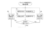
- FIG. 2 is a flowchart of a winch rotation direction notification process of the winch operation notification device according to the embodiment.
- FIG. 3 is a diagram of a rotation direction table stored in a storage unit inside a controller included in the winch operation notification device according to the embodiment.
- FIG. 4 is a diagram of a rotation direction table according to a modification.
- the front-back direction means the front-back direction with respect to a driver's seat provided in a cabin of a crane.
- the winch operation notification device 1 includes a controller 40 that determines whether the winch device 10 of the crane C is operating according to the operation of the winch lever 15 and an operation sound that sounds an operation sound based on the determination result. And a device 50.
- FIG. 1 is a circuit diagram of a hydraulic circuit and an electric circuit of a winch device 10 provided in a crane C to which the winch operation notification device 1 is attached.
- the crane C includes a boom (not shown), a wire rope 132, a hook 131, a winch device 10, a winch operation notification device 1, and the like.
- the boom is, for example, a telescopic boom, and is rotatably fixed to a swivel (not shown) provided on the vehicle body. It should be noted that the boom is not limited to the main jib fixed to the swivel base, but may include a supplementary jib (simply referred to as “jib”) fixed to the tip of the main jib.
- the wire rope 132 is paid out from the drum 13 of the winch device 10 arranged on the swivel table.
- the wire rope 132 is wrapped around a sheave 133 provided at the tip of the boom, and hangs from the sheave 133.
- the hook 131 corresponds to an example of a hanging tool.
- the hook 131 is suspended by a wire rope 132.
- the winch device 10 includes a hydraulic circuit AC, a motor 11, a speed reducer 12, a drum 13, a brake 14, a winch lever 15, and the like.
- the hydraulic circuit AC includes a hydraulic pump 111, a counterbalance valve 112, a relief valve 113, a control valve 114, and the like as actuators. These actuators are provided to drive the motor 11.
- the hydraulic pump 111 operates based on the power of the prime mover 115 to supply hydraulic oil from the oil tank 116 to the hydraulic circuit AC.
- the relief valve 113 opens the valve to release the hydraulic oil to the oil tank 116.
- the relief valve 113 protects the hydraulic circuit AC by preventing the supplied hydraulic oil from being at a pressure higher than the set pressure.
- the counter balance valve 112 is provided between the hydraulic pump 111 and the port P1 of the motor 11.
- the counter balance valve 112 adjusts the amount of hydraulic oil returning from the port P1 of the motor 11 to the oil tank 116. Thereby, the counter balance valve 112 prevents the motor 11 from being rotated by the load of the drum 13.
- the control valve 114 switches the supply path of the hydraulic oil to the motor 11 to switch the rotation direction of the motor 11. That is, the control valve 114 selectively switches between a first path for supplying hydraulic oil to the port P1 of the motor 11 and a second path for supplying hydraulic oil to the port P2.
- the pipe L1 is connected to the port P3 of the control valve 114.
- the pipe L1 connects the port P3 of the control valve 114 and a switching valve 151 (described later) of the winch lever 15.
- the pipe L2 is connected to the port P4 of the control valve 114.
- the pipe L2 connects the port P4 of the control valve 114 and the switching valve 151 of the winch lever 15.
- the motor 11 corresponds to an example of a winch motor and a driving device.
- the motor 11 is a hydraulic motor that rotates an output shaft by flowing hydraulic oil.
- the motor 11 has ports P1 and P2 serving as an inlet or an outlet for hydraulic oil. Note that the motor may be an electric motor.
- the motor 11 has a first output shaft 117 and a second output shaft 118.
- the first output shaft 117 is connected to the speed reducer 12.
- the second output shaft 118 is connected to the brake 14.
- the rotation direction of the motor 11 is switched by a control valve 114.
- the rotation of the motor 11 is transmitted to the speed reducer 12. Further, the rotation of the motor 11 is transmitted to the brake 14.
- the rotation of the motor 11 is transmitted to the drum 13 via the speed reducer 12.
- the speed reducer 12 has a gear (not shown) connected to the first output shaft 117 of the motor 11, and an output shaft 121 connected to the gear.
- the gear reduces the rotation of the first output shaft 117 of the motor 11 and transmits the rotation to the output shaft 121.
- the output shaft 121 is connected to a rotation shaft (not shown) of the drum 13. The output shaft 121 rotates the drum 13.
- the drum 13 corresponds to an example of a winch drum.
- a wire rope 132 is wound around the drum 13.
- the drum 13 raises or lowers the wire rope 132 as it rotates.
- the drum 13 winds up the wire rope 132 by rotating in the forward rotation direction (also referred to as the first rotation direction).
- the drum 13 rotates in the reverse rotation direction (also referred to as a second rotation direction), thereby winding down the wire rope 132.
- the drum 13 moves the hook 131 and the load suspended on the hook 131 upward by winding up the wire rope 132. Further, the drum 13 moves the hook 131 and the suspended load suspended by the hook 131 downward by winding down the wire rope 132.
- the rotation direction of the drum 13 is switched by switching the state of the control valve 114 by the winch lever 15 (described later).
- the brake 14 brakes the rotation of the second output shaft 118 of the motor 11 by hydraulic pressure or a machine.
- the brake 14 maintains the stopped state of the drum 13 by applying a braking force to the second output shaft 118 in a neutral state of the winch lever 15 (described later).
- the brake 14 is released in a first state and a second state (described later) of the winch lever 15.
- the winch lever 15 corresponds to an example of an operation lever, and can swing in the front-rear direction based on an operation of an operator.
- the winch lever 15 is operated by the operator when the operator instructs the operation of the winch device 10.
- the winch lever 15 corresponds to an example of an operation input unit for an operator to input an instruction related to the operation of the winch device 10.
- the winch lever 15 is operated by an operator to be in an upright state (that is, a neutral state not inclined in the front-rear direction), a state inclined backward (also referred to as a first state of the winch lever), and a forward state. State (also referred to as a winch lever second state).
- the winch lever 15 has a switching valve 151.
- the switching valve 151 switches the state of the control valve 114 based on the operation input input from the winch lever 15 operated by the operator.
- the switching valve 151 is connected to the port P3 of the control valve 114 via the pipe L1.
- the switching valve 151 is connected to a port P4 of the control valve 114 via a pipe L2.
- the switching valve 151 is connected to a power source 152.
- the switching valve 151 is supplied with pilot oil from a power source 152.
- the switching valve 151 is connected to the ports P3 and P4 of the control valve 114 and the power source 152, thereby forming a hydraulic circuit PC called a pilot circuit.
- the switching valve 151 is switched according to the state of the winch lever 15. Specifically, the switching valve 151 corresponds to a state corresponding to the neutral state of the winch lever 15 (also referred to as a neutral state of the switching valve) and a first state of the winch lever 15 according to the state of the winch lever 15.
- a state also referred to as a first state of the switching valve
- a state corresponding to the second state of the winch lever 15 also referred to as a second state of the switching valve
- the switching valve 151 is in a state where the pressure of the pilot oil is not applied to both the port P3 and the port P4 of the control valve 114 in the neutral state of the switching valve corresponding to the neutral state of the winch lever 15 (control valve ).
- the control valve 114 In the neutral state of the control valve, the control valve 114 is closed, so that no hydraulic oil is supplied to the motor 11. In the neutral state of the winch lever 15, the brake 14 applies a braking force to the second output shaft 118 of the motor 11. That is, in the neutral state of the winch lever 15, the motor 11 does not rotate. Therefore, in the neutral state of the winch lever 15, the winch device 10 is stopped.
- the switching valve 151 applies a pilot pressure to the port P3 of the control valve 114 in the first state of the switching valve corresponding to the state in which the winch lever 15 is inclined backward (the first state of the winch lever) (the control valve). Of the first state).
- the control valve 114 In the first state of the control valve, no pilot pressure is applied to the port P4 of the control valve 114.
- the control valve 114 When the control valve 114 enters the first state of the control valve, the control valve switches the path for supplying the hydraulic oil to the motor 11 to the first path (that is, the path for supplying the hydraulic oil to the port P1 of the motor 11).
- the winch lever 15 In the first state of the control valve, the winch lever 15 is operated, so that the brake 14 is released. Therefore, in the first state of the winch lever, the motor 11 rotates in the forward rotation direction (first rotation direction). As a result, in the first state of the winch lever, the winch device 10 winds the wire rope 132. When the winch device 10 winds the wire rope 132, the hook 131 fixed to the wire rope 132 moves up (that is, moves upward).
- the switching valve 151 applies a pilot pressure to the port P4 of the control valve 114 (the control valve). In the second state).
- the winch lever 15 In the second state of the control valve, the winch lever 15 is operated, and the brake 14 is released. Therefore, in the second state of the winch lever, the motor 11 rotates in the reverse rotation direction (second rotation direction). As a result, in the second state of the winch lever, the winch device 10 winds down the wire rope 132. When the winch device 10 lowers the wire rope 132, the hook 131 fixed to the wire rope 132 moves down (that is, moves downward).
- the motor 11 when the winch lever 15 is switched to any one of the neutral state, the first state, and the second state, the motor 11 does not rotate according to the state of the winch lever 15. , The state of rotation in the forward rotation direction or the state of rotation in the reverse rotation direction.
- the winch device 10 operates according to the state of the winch lever 15. However, the operation of the winch device 10 may not be executed by one operation of the winch lever 15 due to a phenomenon such as a so-called drop of a suspended load or a slip of the drum 13.
- the winch operation notification device 1 is provided in the winch device 10.
- the winch operation notification device 1 is a device for improving the operability of the winch device 10 by notifying an operator of whether the operation of the winch device 10 is the same as the operation of the winch lever 15.
- the configuration of the winch operation notification device 1 will be described with reference to FIG.
- the winch operation notification device 1 includes an operation direction detector 20, a rotation detector 30, a controller 40, an operation sound device 50, and the like.
- the operation direction detector 20 corresponds to an example of a first detection unit, and detects information related to an operation input for instructing a rotation direction of the motor 11 that rotates the drum 13.
- the operation input is input by the operator operating the winch lever 15.
- the information regarding the operation input is the operation direction of the winch lever 15.
- the operation direction detector 20 detects the operation direction of the winch lever 15, which is information relating to the operation input.
- the operation direction detector 20 has two limit switches 201, 201.
- the limit switch 201 detects a state in which the winch lever 15 is inclined backward (first state of the winch lever). When detecting the first state of the winch lever, the limit switch 201 outputs a detection value (for example, an electric signal) to the operation direction detector 20.
- a detection value for example, an electric signal
- the limit switch 202 detects a state in which the winch lever 15 is inclined forward (second state of the winch lever). When detecting the second state of the winch lever, the limit switch 202 outputs a detection signal (for example, an electric signal) to the operation direction detector 20.
- a detection signal for example, an electric signal
- the winch lever 15 When the limit switches 201 and 202 do not output a detection signal, the winch lever 15 may be regarded as being in a neutral state.
- the operation direction detector 20 detects the operation direction of the winch lever 15 based on the detection signals of the limit switches 201 and 202.
- the operation direction detector 20 outputs information on the detected operation direction of the winch lever 15 to the controller 40.
- the information on the operation direction means information on the operation direction (inclination direction) of the winch lever 15 starting from the neutral state of the winch lever 15.
- the information regarding the operation direction may be regarded as information indicating that the operation direction of the winch lever 15 is any one of “forward”, “rearward”, and “no direction”.
- the operation direction detector 20 may be a pressure switch or a potentiometer instead of the limit switch.
- the pressure switch is a sensor that detects a pilot pressure of the pipe L1 and the pipe L2.
- the potentiometer is a sensor that detects a lever operation angle of the winch lever 15.
- the information regarding the operation input is not limited to the operation direction of the winch lever 15.
- the information on the operation input may be various information corresponding to an operation input (operation of the winch lever 15) for instructing the rotation direction of the motor 11.
- the information on the operation input may be the pressure of the pipe L1 and the pipe L2 (that is, the pilot pressure).
- the information on the operation input may be information on the state of the switching valve 151 and / or the control valve 114.
- the operation input unit for inputting the operation input is not limited to the winch lever 15.
- the operation input unit may be, for example, a button-type switch (not shown) or a touch panel provided on the driver's seat of the crane.
- the operator may input an operation input for instructing the operation of the winch device 10 (the rotation direction of the motor 11) by operating the switch.
- the operation input is not limited to the input based on the operation of the winch lever 15 by the operator.
- the operation input may be an input based on an operation of the button by an operator.
- the operation input may be an operation signal for controlling (instructing) the operation of the winch device 10 (the rotation direction of the motor 11) received from a remote operation terminal for remotely operating the crane C.
- the operation input is, for example, the operation (rotation direction of the motor 11) of the winch device 10 obtained from an external terminal incorporating an application such as BIM (Building Information Modeling) via a network (for example, the Internet).
- An operation signal for controlling (instructing) may be used.
- the operation input is an operation signal for controlling (instructing) the operation of the winch device 10 (the rotation direction of the motor 11) received from an external terminal such as a server via a network (for example, the Internet). You may.
- the operation input is not limited to the input by the operator via the operation input unit. That is, in the automatic operation of the crane C, an operation signal for automatically controlling the operation of the winch device 10 may be regarded as an example of an operation input.
- the rotation detector 30 corresponds to an example of a second detection unit and a detection unit, and detects a direction of an actual operation of the motor 11 or a driven unit driven by the motor 11.
- the speed reducer 12, the drum 13, the wire rope 132, and the hook 131 correspond to an example of a driven part.
- the direction of operation means the rotation direction of the motor 11, the speed reducer 12, and the drum 13.
- the direction of operation of the wire rope 132 means a moving direction in the length direction of the wire rope 132.
- the direction of the operation of the hook 131 means the moving direction (upward or downward) of the hook 131.
- the second detector may be, for example, a sensor that detects the moving direction of the hook 131.
- the second detector is a device that detects the moving direction of the hook 131 by analyzing the image information of the hook 131 acquired from an imaging device such as a camera provided at a position where the hook 131 can be imaged. There may be.
- the camera may be provided on the crane C or around the crane C.
- the rotation detector 30 detects the actual rotation of the motor 11.
- the rotation detector 30 has a rotation sensor facing a gear (not shown) provided on the first output shaft 117 of the motor 11. This rotation sensor outputs a two-phase pulse (so-called A-phase and B-phase square waves) from the unevenness of the gear.
- the rotation detector 30 detects information on the actual rotation direction and / or information on the actual rotation amount of the first output shaft 117 before being decelerated by the speed reducer 12 from the two-phase pulse of the rotation sensor.
- the rotation detector 30 outputs information on the detected rotation direction and / or information on the rotation amount to the controller 40.
- the rotation detector 30 may include a light-emitting element and a light-receiving element instead of the rotation sensor, and may have a reflection encoder that outputs a two-phase pulse from the output of the light-receiving element.
- the controller 40 is an example of a determination unit. Based on the detection value of the operation direction detector 20 and the detection value of the rotation detector 30, the rotation direction of the motor 11 specified by the operation of the winch lever 15 and the motor Then, it is determined whether or not the actual rotation direction is the same as the actual rotation direction. The controller 40 controls the operation of the operation sound device 50 based on the determination result.
- the controller 40 acquires outputs (detected values) of the operation direction detector 20 and the rotation detector 30.
- the controller 40 is realized by a CPU (Central Processing Unit) executing a winch rotation direction notification program.
- the controller 40 compares the information on the rotation direction acquired from the rotation detector 30 with the information on the operation direction acquired from the operation direction detector 20 to determine that the actual rotation direction of the motor 11 is the same as the operation direction of the winch lever 15. It is determined whether or not the operation is compatible, that is, whether or not the motor 11 is rotating as the winch lever 15 is operated.
- the controller 40 determines that the actual rotation direction of the motor 11 does not correspond to the operation direction of the winch lever 15, the controller 40 outputs the first operating sound signal having a fixed pulse width, that is, a fixed signal length, to the operating sound device. Output to 50.
- the controller 40 determines that the actual rotation direction of the motor 11 corresponds to the operation direction of the winch lever 15, the controller 40 outputs the second operation sound signal having a signal length different from the first operation sound signal to the operation sound device. Output to 50.
- the controller 40 generates the first operation sound signal or the second operation sound signal at a frequency corresponding to the information on the rotation amount received from the rotation detector 30 (also referred to as rotation amount data), in other words, for each predetermined rotation amount. Output.
- the first operation sound signal or the second operation sound signal is also referred to as a direction signal.
- the operation sound device 50 corresponds to an example of a notification unit, and emits an operation sound based on an output of the controller 40.
- the operation sound device 50 has a buzzer including a diaphragm that generates sound by vibration.
- the operation sound device 50 generates an operation sound by vibrating the diaphragm of the buzzer based on the first operation sound signal or the second operation sound signal of the controller 40.
- the signal length of the first operation sound signal differs from that of the second operation sound signal as described above. Therefore, the first operation sound output from the operation sound device 50 based on the first operation sound signal and the second operation sound output from the operation sound device 50 based on the second operation sound signal are output frequency and And / or the nature of the sound (pitch, etc.) is different Thereby, the operation sound device 50 notifies the operator whether the gear of the motor 11 is rotating as the winch lever 15 is operated.
- the sound output from the operating sound device 50 based on the first operating sound signal is referred to as a first operating sound
- the sound output from the operating sound device 50 based on the second operating sound signal is referred to as a second operating sound signal. It is called operating noise.
- the first operation sound and the second operation sound are also referred to as a notification sound.
- the first operation sound corresponds to an example of first notification information.
- the second operation sound corresponds to an example of the second notification information.
- means for notifying the worker of the first operation sound is also referred to as first notification means.
- Means for notifying the operator of the second operation sound is also referred to as second notification means.
- the operating sound device 50 is also called an alarm.
- the controller 40 outputs the first operation sound signal or the second operation sound signal to the operation sound device 50 every time the motor 11 rotates by a predetermined rotation amount. For this reason, the operation sound device 50 outputs an operation sound every time the motor 11 rotates by a predetermined rotation amount, and notifies an operator of the degree of rotation of the motor 11. Since the rotation amount of the motor 11 is proportional to the rotation amount of the drum 13 of the winch device 10, the operator can recognize the magnitude of the rotation amount of the drum 13 from the frequency of the operation sound of the operation sound device 50.
- FIG. 2 is a flowchart of a winch rotation direction informing process of the winch operation informing device 1 according to the embodiment.
- FIG. 3 is a diagram of the rotation direction table 41 stored in a storage unit inside the controller 40 provided in the winch operation notification device 1.
- the winch rotation direction notification program When the PTO switch is turned on in the crane C, the execution of the winch rotation direction notification program is started. As a result, the winch rotation direction notification process shown in FIG. 2 starts. It may be considered that the winch rotation direction notification processing is executed by a processor mounted on the crane C.
- the controller 40 acquires information on the operation direction (also referred to as operation direction data) from the operation direction detector 20 (step S1).
- the operation direction detector 20 outputs information on the operation direction indicating “no direction”. For this reason, the controller 40 acquires information on the operation direction indicating “no direction” from the operation direction detector 20.
- the controller 40 acquires information on the rotation direction (also referred to as rotation direction data) from the rotation detector 30 (Step S2). At this time, the controller 40 may also obtain information on the amount of rotation from the rotation detector 30.
- a step in which the rotation detector 30 detects the rotation of the motor 11 is referred to as a rotation detection step.
- the controller 40 compares the information on the rotation direction acquired from the rotation detector 30 with the information on the operation direction acquired from the operation direction detector 20. At this time, the controller 40 reads the rotation direction table 41 shown in FIG. 3 from the storage unit.
- the rotation direction table 41 stores information on the operation direction (operation direction data) in association with the direction in which the motor 11 should rotate.
- step S3 a comparison is made between the actual rotation direction of the motor 11 indicated by the information on the acquired rotation direction and the direction in which the motor 11 should be acquired from the rotation direction table 41, and as shown in FIG. It is determined whether they match.
- the controller 40 has obtained information on the operation direction indicating “no direction” from the operation direction detector 20. Therefore, the direction to be rotated in the rotation direction table 41 is “no direction”. The controller 40 determines whether or not the actual rotation direction of the motor 11 indicated by the information on the rotation direction is “no direction”.
- step S3 If the actual rotation direction of the motor 11 indicated by the information on the rotation direction does not match “no direction” (“No” in step S3), the controller 40 operates the winch device 10 in an operation different from the operation direction of the winch lever 15 ( That is, it is determined that an unsupported operation is being performed. Note that, in this specification, the step performed in step S3 is referred to as a determination step.
- the controller 40 outputs a first operation sound signal having a fixed signal length to the operation sound device 50 (step S4).
- the first operation sound signal is output for each predetermined rotation amount based on information on the rotation amount of the rotation detector 30.
- the operation sound device 50 outputs the first operation sound at a frequency corresponding to the rotation amount of the motor 11.
- the process performed in step S4 is referred to as a notification process.
- the controller 40 may output the first operation sound signal to the operation sound device 50 at a frequency not corresponding to the rotation amount of the motor 11.
- the worker has two types of sounds, the first operation sound and the second operation sound, output from the operation sound device 50, and the first operation sound is rotating in a direction different from the direction in which the motor 11 should rotate. It is preferable that the user be informed in advance that the notification is made and that the second operation sound is notified that the motor 11 is rotating in the direction in which the motor 11 should rotate.
- step S4 the operator knows in advance that the frequency of the first operation sound and the second operation sound is a frequency corresponding to the rotation amount of the motor 11.
- the first operation sound is output by the operation sound device 50 even though the winch lever 15 is in the neutral state. Therefore, the operator recognizes that the drum 13 is rotating even though the winch device 10 is stopped.
- step S4 the controller 40 returns the winch rotation direction notification processing to step S1 while continuing to output the first operation sound signal (step S4). After the output of the first operating sound signal is returned to step S1, the processing from step S1 to step S3 is continued. This is the same also when outputting the second operation sound signal in step S5 described later.
- step S3 the controller 40 causes the winch device 10 to operate as the winch lever 15 operates. Is determined to have been performed.
- step S5 in FIG. 2 is not performed. That is, in the case of this operation example, the actual rotation direction of the motor 11 indicated by the information on the rotation direction is “no direction”, and the rotation direction indicated by the information on the operation direction is “no direction”.
- the second operation sound signal is not output to the operation sound device 50.
- the operation sound device 50 does not output the second operation sound.
- the controller 40 returns the winch rotation direction notification processing to step S1 (step S5).
- the winch rotation direction notification process is performed until the PTO switch is turned off. For this reason, the controller 40 repeats the above-described processing from step S1 to step S3 while the PTO switch is turned on. As a result, while the PTO switch is turned on, the controller 40 always informs the operator of the comparison result between the information on the operation direction and the information on the rotation direction, and as intended by the operator who operated the winch lever 15. Then, information indicating whether or not the motor 11 is rotating is fed back to the operator.
- Step S1 When the winch lever 15 is tilted backward (first state of the winch lever), the controller 40 acquires information (also referred to as operation direction data) on the operation direction indicating “rearward” from the operation direction detector 20. (Step S1).
- the controller 40 acquires information on the actual rotation direction of the motor 11 (also referred to as rotation direction data) and / or information on the actual rotation amount (also referred to as rotation amount data) from the rotation detector 30 (refer to FIG. 4). Step S2).
- the controller 40 compares the actual rotation direction of the motor 11 indicated by the information on the rotation direction acquired from the rotation detector 30 with the direction in which the motor 11 in the rotation direction table 41 should rotate (step S3).
- the operation direction of the winch lever 15 indicated by the information on the operation direction is “rear”.
- the direction to be rotated in the rotation direction table 41 is the “forward rotation direction”.
- the controller 40 determines whether or not the actual rotation direction of the motor 11 indicated by the information on the rotation direction is the “forward rotation direction”.
- the controller 40 determines a predetermined value based on the information on the rotation amount of the rotation detector 30.
- the first operation sound signal is output to the operation sound device 50 for each rotation amount of (Step S4).
- the operation sound device 50 that has received the first operation sound signal outputs the first operation sound.
- the controller 40 may output the first operation sound signal to the operation sound device 50 at a frequency that does not correspond to the rotation amount of the motor 11.
- step S3 when the actual rotation direction of the motor 11 indicated by the information on the rotation direction matches the “forward rotation direction” (“Yes” in step S3), the controller 40 determines the predetermined rotation amount based on the information on the rotation amount.
- the second operation sound signal is output every time (step S5). Note that the controller 40 may output the second operation sound signal to the operation sound device 50 at a frequency not corresponding to the rotation amount of the motor 11.
- the operation sound device 50 outputs a second operation sound based on the acquired second operation sound signal.
- the controller 40 outputs the first operation sound or the second operation sound according to whether the actual rotation direction of the motor 11 indicated by the information on the rotation direction matches the “forward rotation direction”.
- the operation sound device 50 is controlled as described above.
- the operator can recognize whether or not the winch device 10 winds the wire rope 132 as the winch lever 15 is operated, based on the type of sound.
- the controller 40 Since the winch lever 15 is inclined forward (the second state of the winch lever), the controller 40 obtains information on the operation direction indicating “forward” from the operation direction detector 20 in step S1 shown in FIG. I do.
- the controller 40 acquires information on the actual rotation direction of the motor 11 and / or information on the actual rotation amount from the rotation detector 30 (Step S2).
- the controller 40 compares the actual rotation direction of the motor 11 indicated by the information on the rotation direction acquired from the rotation detector 30 with the direction in which the motor 11 of the rotation direction table 41 should rotate.
- the controller 40 has acquired information on the operation direction indicating “forward” from the operation direction detector 20. For this reason, the direction to be rotated in the rotation direction table 41 is the “reverse rotation direction”. The controller 40 determines whether or not the actual rotation direction of the motor 11 indicated by the information on the rotation direction is the “reverse rotation direction”.
- the controller 40 determines the number of rotations for each predetermined rotation amount based on the information on the rotation amount. Then, the first operation sound signal is output to the operation sound device 50 (step S4). Then, the operation sound device 50 that has received the first operation sound signal outputs the first operation sound. Note that the controller 40 may output the first operation sound signal to the operation sound device 50 at a frequency that does not correspond to the rotation amount of the motor 11.
- step S3 If the actual rotation direction of the motor 11 indicated by the information on the rotation direction matches the “reverse rotation direction” (“Yes” in step S3), the controller 40 performs the process for each predetermined rotation amount based on the information on the rotation amount.
- the second operation sound signal is output to the operation sound device 50 (step S5). Note that the controller 40 may output the second operation sound signal to the operation sound device 50 at a frequency not corresponding to the rotation amount of the motor 11.
- the operation sound device 50 that has received the second operation sound signal outputs the second operation sound. Accordingly, the controller 40 generates the first operation sound or the second operation sound according to whether the actual rotation direction of the motor 11 indicated by the information on the rotation direction matches the “reverse rotation direction”. Output. As a result, the operator can recognize whether or not the winch device 10 is lowering the wire rope 132 according to the operation of the winch lever 15 based on the type of sound.
- the controller 40 of the winch operation notification device 1 performs the operation based on the actual rotation direction of the motor 11 detected by the rotation detector 30 and the operation direction of the winch lever 15 detected by the operation direction detector 20. It is determined whether or not the motor 11 is rotating in the same direction as the operation direction of the winch lever 15.
- the controller 40 causes the operation sound device 50 to output the first operation sound or the second operation sound based on the determination result.
- the operator can recognize whether or not the winch device 10 is operating according to the operation of the winch lever 15 based on the type of sound. Since the operator operates the winch device 10 after recognizing the actual operation, the winch operation notification device 1 can enhance the operability of the winch device 10.
- the rotation detector 30 detects the rotation direction of the motor 11. That is, the rotation direction before being decelerated by the speed reducer 12 is detected.
- the rotation detector 30 may detect the rotation direction of the speed reducer 12. In this case, since the rotation of the motor 11 is reduced, the rotation direction and the rotation amount can be detected with higher accuracy than when the rotation of the motor 11 is directly detected from the first output shaft 117. Thereby, it is possible to determine with high accuracy whether or not the operation of the winch device 10 is in accordance with the operation of the winch lever 15, and the operability of the winch device 10 can be further improved.
- the controller 40 determines whether the motor 11 is rotating in the same direction as the operation direction of the winch lever 15 based on the rotation direction of the rotation detector 30 and the operation direction of the operation direction detector 20. Determine whether or not. Then, based on the determination result, the operation sound device 50 outputs the first operation sound signal or the second operation sound signal.
- the rotation detector 30 may transmit a direction signal, that is, a first operation sound signal or a second operation sound signal. In this case, the operation sound device 50 receives the first operation sound signal or the second operation sound signal from the rotation detector 30 and changes the rotation direction of the motor 11 based on the first operation sound signal or the second operation sound signal. You may report. Even in such a form, the winch device 10 can be operated after the operator recognizes the actual operation of the drum 13.
- the controller 40 may determine whether or not the actual rotation direction of the motor 11 is the same as the operation direction of the winch lever 15. In this case, when the controller 40 determines that the actual rotation direction of the motor 11 is not the same as the operation direction of the winch lever 15, the operation sound device 50 outputs an operation sound. As a result, the operator can be notified that the winch device 10 is not operating according to the operation of the winch lever 15.
- the controller 40 determines the actual rotation direction and the operation direction of the motor 11. It is determined that the rotation direction of the motor 11 indicated by the information about the motor does not match. Then, the operation sound device 50 outputs the second operation sound.
- the present invention is not limited to this.
- FIG. 4 is a diagram of a rotation direction table 42 according to a modification.
- the rotation direction table 42 when the operation direction of the winch lever 15 is “forward”, the rotation direction table 42 is set such that the direction in which the motor 11 should rotate is “reverse rotation direction” or “no direction”. You may.
- the direction in which the motor 11 should rotate may be set to "forward rotation direction” or "no direction”.
- the controller 40 determines the actual rotation direction of the motor 11 indicated by the information on the rotation direction and the operation.
- the controller 40 controls the operation sound device 50 so as not to notify the first operation sound and the second operation sound.
- the operation sound device 50 outputs an operation sound only when the winch device 10 is hoisting or lowering.
- the operating sound device 50 notifies the worker by outputting a sound.
- the winch operation notification device 1 may include an alarm that notifies an operator whether the operation is different from the operation of the winch lever 15. Therefore, the operation sound device 50 may be replaced with a light emitting device (for example, a lamp or a liquid crystal display device) that notifies an operator by emitting light. In this case, the light emitting pattern of the light emitting device may be changed to notify the worker whether the operation is different from the operation of the winch lever 15. Further, the light emitting device may blink at predetermined rotation amounts based on the rotation amount data detected by the rotation detector 30.
- a light emitting device for example, a lamp or a liquid crystal display device
- the operating sound device 50 may be replaced with a vibration generating device that vibrates the winch lever 15 to notify the worker.
- the operator may be notified of whether the operation is different from the operation of the winch lever 15 by changing the vibration pattern, for example, the frequency.
- the vibration generating device may vibrate at every predetermined rotation amount, similarly to the light emitting device described above.
- the operation sound device 50 may generate only the first operation sound in order to notify the operator that the operation is different from the operation of the winch lever 15.
- the light emission or the vibration may be performed only when the controller 40 determines that the operation is different from the operation.
- the operating sound device 50 may output sounds of different pitches for the first operating sound and the second operating sound. For example, if the first operation sound is higher than the second operation sound, the operator can easily notice that the operation is different.
- different colors may be emitted depending on whether the controller 40 determines that the operation is different from the operation, or when the controller 40 determines that the operation is the same as the operation.
- the light emission may be performed by changing the blinking frequency or the light emission intensity.
- the operation sound device 50 outputs the first operation sound or the second operation sound for each predetermined rotation amount based on the rotation amount data of the rotation detector 30. However, in the present invention, it is optional whether or not the operation sound device 50 outputs the first operation sound or the second operation sound for each predetermined rotation amount.
- the operation sound device 50 may output a first operation sound or a second operation sound having a pitch corresponding to the rotation amount data of the rotation detector 30. In this case, the signal lengths of the first operation sound signal and the second operation sound signal generated by the controller 40 may be different.
- the operation sound device 50 may output the operation sound only when the rotation amount data of the rotation detector 30 exceeds a certain threshold value or only when the rotation amount data is less than the certain threshold value.
- the operation sound may be the first operation sound or the second operation sound that sounds at a high frequency.
- the operating sound may be muted or the volume adjusted by the operator operating the winch operation notifying device 1.
- the winch operation notification device 1 may include an operation unit, and the operation sound of the operation sound device 50 may be stopped or changed by operating the operation unit.
- the winch operation notification device 1 includes an operation unit, the above-described constant threshold value may be changed by inputting threshold data to the operation unit.
- the operation sound device 50 may output the first operation sound or the second operation sound at a frequency that increases stepwise as the rotation amount increases.
- the present invention is also applicable to a sub winch provided in a crane. Therefore, the present invention is applicable to a crane including at least one of the winch device 10 and the sub winch.
- the present invention can be applied to a rough terrain crane, a truck crane, and the like.
- the notification device, crane, and notification method according to the present invention can be applied to various cranes.
Landscapes
- Engineering & Computer Science (AREA)
- Mechanical Engineering (AREA)
- Control And Safety Of Cranes (AREA)
Abstract
報知装置は、ウインチドラムを回転させる駆動装置の回転方向を指示するための操作入力を検出する第一検出部と、駆動装置又は駆動装置により駆動される被駆動部の実際の動作の方向を検出する第二検出部と、第一検出部の検出値と第二検出部の検出値とに基づいて、操作入力により指示された駆動装置の回転方向と、駆動装置又は非駆動部の実際の動作の方向とが対応しているか否かを判定する判定部と、判定部の判定結果に対応する情報を報知する報知部と、を備える。
Description
本発明は報知装置、クレーン、及び報知方法に関する。
従来から、ウインチ装置が有するドラムの回転状態を検出する装置を備えたクレーンが知られている。例えば、特許文献1には、クレーンに取り付けられる安全装置が開示されている。特許文献1に記載の安全装置は、ドラムの回転からウインチの巻き上げ速度を求める。そして、この安全装置は、求めた巻き上げ速度と巻き上げ速度の履歴とを比較して、ドラムの回転動作を判定する。
又、特許文献2には、クレーンに取り付けられるドラムの監視装置が開示されている。特許文献2に記載の監視装置は、ブレーキが解除された状態でドラムが回転しているか否かを監視する。
一方、クレーンの操作において、僅かな距離だけ吊荷を上昇又は下降させる微動操作を行うことがある。このような微動操作において、ウインチによる巻き上げを開始する際、作業者は、ブレーキを解除する。すると、ブレーキを解除した瞬間、吊荷及びフック等の自重によって吊荷が僅かに下降する、いわゆる寸落が発生することがある。
又、微動操作においてウインチによる巻き上げを開始する際、ドラムを回転させるモータに供給される油の量が、そのモータから漏れる油の量よりも少なくなることがある。この場合、モータが巻き下げ方向に回転して、いわゆるスリップが発生することがある。このように、微動操作において、ウインチは、作業者の意図しない方向に動作することがある。
しかし、特許文献1及び特許文献2に記載の安全装置及び監視装置では、上述の微動操作における寸落又はスリップを検出できない。このため、特許文献1及び特許文献2に開示された安全装置及び監視装置は、ウインチが作業者の意図しない方向に動作したことを検出できない。よって、特許文献1及び特許文献2に開示された安全装置及び監視装置は、微動操作におけるウインチの操作性を向上させることはできない。
本発明は、上記の課題を解決するためになされたもので、ウインチの操作性を向上できる報知装置、クレーン、及び報知方法を提供することを目的とする。
本発明に係る報知装置の一態様は、ウインチドラムを回転させる駆動装置の回転方向を指示するための操作入力を検出する第一検出部と、駆動装置又は駆動装置により駆動される被駆動部の実際の動作の方向を検出する第二検出部と、第一検出部の検出値と第二検出部の検出値とに基づいて、操作入力により指示された駆動装置の回転方向と、上記実際の動作の方向とが対応しているか否かを判定する判定部と、判定部の判定結果に対応する情報を報知する報知部と、を備える。
本発明に係るクレーンの一態様は、上述の報知装置を備える。
本発明に係る報知方法の一態様は、ブームと、ワイヤロープと、ワイヤロープの巻き上げ及び巻き下げを行うウインチ装置と、ワイヤロープを介してブームの先端部から吊り下げられた吊り具と、を備えたクレーンに搭載されたプロセッサーで実行される報知方法であって、ウインチドラムを回転させる駆動装置の回転方向を指示するための操作入力に関する情報を検出するステップと、駆動装置又は駆動装置により駆動される被駆動部の実際の動作の方向を検出するステップと、検出された操作入力に関する情報と検出された上記実際の動作の方向とに基づいて、操作入力により指示された駆動装置の回転方向と、実際の動作の方向とが対応しているか否かの判定を行うステップと、この判定の結果に対応する情報を報知するステップと、を含む。
本発明によれば、ウインチの操作性を向上できる報知装置、クレーン、及び報知方法を実現できる。
以下、本発明の実施形態に係るウインチ動作報知装置1、クレーンC、及びウインチ動作報知方法について図面を参照して詳細に説明する。尚、図中、同一又は同等の部分には同一の符号を付す。又、本明細書において、前後方向は、クレーンのキャビンに設けられた運転席に対する前後方向を意味する。
[実施形態]
本実施形態のウインチ動作報知装置1は、ウインチレバー15の操作どおりにクレーンCのウインチ装置10が動作しているか否かを判定するコントローラ40と、その判定結果に基づいて作動音を鳴らす作動音装置50と、を備える報知装置である。
本実施形態のウインチ動作報知装置1は、ウインチレバー15の操作どおりにクレーンCのウインチ装置10が動作しているか否かを判定するコントローラ40と、その判定結果に基づいて作動音を鳴らす作動音装置50と、を備える報知装置である。
先ず、図1を参照して、ウインチ装置10が搭載されたクレーンCの構成について説明する。次に、ウインチ装置10の動作を報知するウインチ動作報知装置1の構成について説明する。その後、図2及び図3を参照して、ウインチ動作報知装置1の動作について説明する。
図1は、ウインチ動作報知装置1が取り付けられるクレーンCが備えるウインチ装置10の油圧回路、及び、電気回路の回路図である。
クレーンCは、ブーム(不図示)、ワイヤロープ132、フック131、ウインチ装置10、及びウインチ動作報知装置1等を備える。
<ブーム>
ブームは、例えば、伸縮式ブームであって、車体に設けられた旋回台(不図示)に旋回可能に固定されている。尚、ブームは、旋回台に固定された主ジブに限らず、主ジブの先端に固定される補ジブ(単に「ジブ」とも称する。)を含むと捉えてよい。
ブームは、例えば、伸縮式ブームであって、車体に設けられた旋回台(不図示)に旋回可能に固定されている。尚、ブームは、旋回台に固定された主ジブに限らず、主ジブの先端に固定される補ジブ(単に「ジブ」とも称する。)を含むと捉えてよい。
<ワイヤロープ>
ワイヤロープ132は、旋回台に配置されたウインチ装置10のドラム13から繰り出されている。ワイヤロープ132は、ブームの先端部に設けられたシーブ133に掛け回され、シーブ133から垂れ下がっている。
ワイヤロープ132は、旋回台に配置されたウインチ装置10のドラム13から繰り出されている。ワイヤロープ132は、ブームの先端部に設けられたシーブ133に掛け回され、シーブ133から垂れ下がっている。
<フック>
フック131は、吊り具の一例に該当する。フック131は、ワイヤロープ132により吊られている。
フック131は、吊り具の一例に該当する。フック131は、ワイヤロープ132により吊られている。
<ウインチ装置>
図1に示すように、ウインチ装置10は、油圧回路ACと、モータ11、減速機12、ドラム13、ブレーキ14、及びウインチレバー15等、を有する。
図1に示すように、ウインチ装置10は、油圧回路ACと、モータ11、減速機12、ドラム13、ブレーキ14、及びウインチレバー15等、を有する。
<油圧回路>
油圧回路ACは、アクチュエータとして、油圧ポンプ111、カウンタバランスバルブ112、リリーフバルブ113、及びコントロールバルブ114等を有する。これらのアクチュエータは、モータ11を駆動するために設けられている。
油圧回路ACは、アクチュエータとして、油圧ポンプ111、カウンタバランスバルブ112、リリーフバルブ113、及びコントロールバルブ114等を有する。これらのアクチュエータは、モータ11を駆動するために設けられている。
具体的には、油圧ポンプ111は、原動機115の動力に基づいて作動することにより、オイルタンク116から油圧回路ACに作動油を供給する。
リリーフバルブ113は、供給された作動油が設定以上の圧力になると、バルブを開けて作動油をオイルタンク116に逃がす。これにより、リリーフバルブ113は、供給された作動油が設定以上の圧力になることを防いで油圧回路ACを保護する。
カウンタバランスバルブ112は、油圧ポンプ111とモータ11のポートP1との間に設けられている。カウンタバランスバルブ112は、モータ11のポートP1からオイルタンク116へ戻る作動油の油量を調整する。これにより、カウンタバランスバルブ112は、ドラム13の負荷によってモータ11が回転させられることを防止する。
コントロールバルブ114は、モータ11への作動油の供給経路を切り換えて、モータ11の回転方向を切り換える。即ち、コントロールバルブ114は、モータ11のポートP1に作動油を供給する第一経路と、ポートP2に作動油を供給する第二経路と、を選択的に切り換える。
コントロールバルブ114のポートP3には、配管L1が接続されている。配管L1は、コントロールバルブ114のポートP3とウインチレバー15の切換バルブ151(後述)とを接続している。
又、コントロールバルブ114のポートP4には、配管L2が接続されている。配管L2は、コントロールバルブ114のポートP4とウインチレバー15の切換バルブ151とを接続している。
<モータ>
モータ11は、ウインチモータ及び駆動装置の一例に該当する。モータ11は、流入する作動油により出力軸を回転させる油圧モータである。モータ11は、作動油の流入口又は排出口となるポートP1、P2を有する。尚、モータは、電動モータであってもよい。
モータ11は、ウインチモータ及び駆動装置の一例に該当する。モータ11は、流入する作動油により出力軸を回転させる油圧モータである。モータ11は、作動油の流入口又は排出口となるポートP1、P2を有する。尚、モータは、電動モータであってもよい。
モータ11は、第一出力軸117と、第二出力軸118とを有する。第一出力軸117は、減速機12に接続されている。第二出力軸118は、ブレーキ14に接続されている。モータ11は、コントロールバルブ114によって回転方向が切り換えられる。モータ11の回転は、減速機12に伝わる。又、モータ11の回転は、ブレーキ14にも伝わる。モータ11の回転は、減速機12を介してドラム13に伝わる。
<減速機>
減速機12は、モータ11の第一出力軸117に接続されたギア(不図示)と、ギアに接続された出力軸121と、を有する。ギアは、モータ11の第一出力軸117の回転を減速して出力軸121に伝える。出力軸121は、ドラム13の回転軸(不図示)に接続されている。出力軸121は、ドラム13を回転させる。
減速機12は、モータ11の第一出力軸117に接続されたギア(不図示)と、ギアに接続された出力軸121と、を有する。ギアは、モータ11の第一出力軸117の回転を減速して出力軸121に伝える。出力軸121は、ドラム13の回転軸(不図示)に接続されている。出力軸121は、ドラム13を回転させる。
<ドラム>
ドラム13は、ウインチドラムの一例に該当する。ドラム13には、ワイヤロープ132が巻回されている。ドラム13は、自身の回転にともない、ワイヤロープ132の巻き上げ又は巻き下げを行う。
ドラム13は、ウインチドラムの一例に該当する。ドラム13には、ワイヤロープ132が巻回されている。ドラム13は、自身の回転にともない、ワイヤロープ132の巻き上げ又は巻き下げを行う。
ドラム13は、正回転方向(第一回転方向とも称する。)に回転することにより、ワイヤロープ132を巻き上げる。又、ドラム13は、逆回転方向(第二回転方向とも称する。)に回転することにより、ワイヤロープ132を巻き下げる。
これにより、ドラム13は、ワイヤロープ132を巻き上げることにより、フック131及びフック131に吊られた吊荷を上方に移動させる。又、ドラム13は、ワイヤロープ132を巻き下げることにより、フック131及びフック131に吊られた吊荷を下方に移動させる。ドラム13の回転方向は、ウインチレバー15(後述)によってコントロールバルブ114の状態が切り換えられることにより、切り換えられる。
<ブレーキ>
ブレーキ14は、油圧又は機械によってモータ11の第二出力軸118の回転を制動する。ブレーキ14は、ウインチレバー15の中立状態(後述)において、第二出力軸118に制動力を付与することにより、ドラム13の停止状態を維持する。
ブレーキ14は、油圧又は機械によってモータ11の第二出力軸118の回転を制動する。ブレーキ14は、ウインチレバー15の中立状態(後述)において、第二出力軸118に制動力を付与することにより、ドラム13の停止状態を維持する。
又、ブレーキ14は、ウインチレバー15の第一状態及び第二状態(後述)において、解除される。
<ウインチレバー>
ウインチレバー15は、操作レバーの一例に該当し、作業者の操作に基づいて、前後方向に揺動可能である。ウインチレバー15は、作業者がウインチ装置10の動作を指示する際、作業者により操作される。ウインチレバー15は、作業者がウインチ装置10の動作に関する指示を入力するための操作入力部の一例に該当する。
ウインチレバー15は、操作レバーの一例に該当し、作業者の操作に基づいて、前後方向に揺動可能である。ウインチレバー15は、作業者がウインチ装置10の動作を指示する際、作業者により操作される。ウインチレバー15は、作業者がウインチ装置10の動作に関する指示を入力するための操作入力部の一例に該当する。
ウインチレバー15は、作業者によって操作されることで、直立した状態(つまり、前後方向に傾斜していない中立状態)、後方に傾斜した状態(ウインチレバーの第一状態とも称する。)、及び前方へ傾斜した状態(ウインチレバーの第二状態とも称する。)のうちの何れか一つの状態を取り得る。
ウインチレバー15は、切換バルブ151を有する。切換バルブ151は、作業者に操作されたウインチレバー15から入力された操作入力に基づいて、コントロールバルブ114の状態を切り換える。
具体的には、切換バルブ151は、配管L1を介して、コントロールバルブ114のポートP3に接続されている。又、切換バルブ151は、配管L2を介して、コントロールバルブ114のポートP4に接続されている。又、切換バルブ151は、動力源152に接続されている。切換バルブ151は、動力源152からパイロット油を供給されている。
切換バルブ151は、コントロールバルブ114のポートP3及びポートP4と、動力源152と、に接続されることで、パイロット回路と呼ばれる油圧回路PCを形成している。
切換バルブ151は、ウインチレバー15の状態に応じて、切り換えられる。具体的には、切換バルブ151は、ウインチレバー15の状態に応じて、ウインチレバー15の中立状態に対応する状態(切換バルブの中立状態とも称する。)、ウインチレバー15の第一状態に対応する状態(切換バルブの第一状態とも称する。)、及びウインチレバー15の第二状態に対応する状態(切換バルブの第二状態とも称する。)との何れかの状態を取り得る。
作業者の操作に基づいて、ウインチレバー15の状態が切り換わると、ウインチレバー15の状態に応じて切換バルブ151の状態が切り換わる。
具体的には、切換バルブ151は、ウインチレバー15の中立状態に対応する切換バルブの中立状態において、コントロールバルブ114のポートP3及びポートP4のいずれにもパイロット油の圧力を加えない状態(コントロールバルブの中立状態とも称する。)となる。
コントロールバルブの中立状態において、コントロールバルブ114は閉じられるため、作動油は、モータ11に供給されない。尚、ウインチレバー15の中立状態において、ブレーキ14は、モータ11の第二出力軸118に制動力を付与している。つまり、ウインチレバー15の中立状態において、モータ11は回転しない。よって、ウインチレバー15の中立状態において、ウインチ装置10は停止している。
又、切換バルブ151は、ウインチレバー15が後方に傾斜した状態(ウインチレバーの第一状態)に対応する切換バルブの第一状態において、コントロールバルブ114のポートP3にパイロット圧を加える状態(コントロールバルブの第一状態とも称する)となる。
コントロールバルブの第一状態において、コントロールバルブ114のポートP4には、パイロット圧は加わっていない。コントロールバルブ114は、コントロールバルブの第一状態になると、モータ11に作動油を供給する経路を第一経路(つまり、モータ11のポートP1に作動油を供給する経路)に切り換える。
尚、コントロールバルブの第一状態において、ウインチレバー15が操作されているため、ブレーキ14は、解除されている。よって、ウインチレバーの第一状態において、モータ11は、正回転方向(第一回転方向)に回転する。この結果、ウインチレバーの第一状態において、ウインチ装置10は、ワイヤロープ132を巻き上げる。ウインチ装置10によるワイヤロープ132の巻き上げが行われると、ワイヤロープ132に固定されたフック131は、上昇する(つまり、上方に移動する)。
又、切換バルブ151は、ウインチレバー15が前方に傾斜した状態(ウインチレバーの第二状態)に対応する切換バルブの第二状態において、コントロールバルブ114のポートP4にパイロット圧を加える状態(コントロールバルブの第二状態とも称する)となる。
コントロールバルブの第二状態において、コントロールバルブ114のポートP3には、パイロット圧は加わっていない。コントロールバルブ114は、コントロールバルブの第二状態になると、モータ11に作動油を供給する経路を第二経路(つまり、モータ11のポートP2に作動油を供給する経路)に切り換える。
尚、コントロールバルブの第二状態において、ウインチレバー15が操作されているため、ブレーキ14は、解除されている。よって、ウインチレバーの第二状態において、モータ11は、逆回転方向(第二回転方向)に回転する。この結果、ウインチレバーの第二状態において、ウインチ装置10は、ワイヤロープ132を巻き下げる。ウインチ装置10によるワイヤロープ132の巻き下げが行われると、ワイヤロープ132に固定されたフック131は、下降する(つまり、下方に移動する)。
以上のようなウインチ装置10において、ウインチレバー15が中立状態、第一状態、又は第二状態の何れかの状態に切り換えられると、モータ11は、ウインチレバー15の状態に応じて、回転しない状態、正回転方向に回転する状態、又は逆回転方向に回転する状態の何れかの状態に切り換えられる。
ウインチ装置10は、ウインチレバー15の状態に応じて動作する。しかし、ウインチ装置10の動作は、いわゆる吊荷の寸落、ドラム13のスリップ等の現象によって、ウインチレバー15の操作1りに実行されないことがある。
そこで、本実施形態の場合、ウインチ装置10にウインチ動作報知装置1が設けられている。ウインチ動作報知装置1は、ウインチ装置10の動作がウインチレバー15の操作どおりの動作であるか否かを作業者に報知することにより、ウインチ装置10の操作性を高めるための装置である。以下、図1を参照して、ウインチ動作報知装置1の構成について説明する。
<ウインチ動作報知装置>
ウインチ動作報知装置1は、操作方向検出器20、回転検出器30、コントローラ40、及び作動音装置50等を備える。
ウインチ動作報知装置1は、操作方向検出器20、回転検出器30、コントローラ40、及び作動音装置50等を備える。
<操作方向検出器>
操作方向検出器20は、第一検出部の一例に該当し、ドラム13を回転させるモータ11の回転方向を指示するための操作入力に関する情報を検出する。本実施形態の場合、操作入力は、作業者がウインチレバー15を操作することにより入力される。本実施形態の場合、操作入力に関する情報は、ウインチレバー15の操作方向である。
操作方向検出器20は、第一検出部の一例に該当し、ドラム13を回転させるモータ11の回転方向を指示するための操作入力に関する情報を検出する。本実施形態の場合、操作入力は、作業者がウインチレバー15を操作することにより入力される。本実施形態の場合、操作入力に関する情報は、ウインチレバー15の操作方向である。
つまり、操作方向検出器20は、操作入力に関する情報である、ウインチレバー15の操作方向を検出する。操作方向検出器20は、2つのリミットスイッチ201、201を有する。
リミットスイッチ201は、ウインチレバー15が後方に傾斜した状態(ウインチレバーの第一状態)を検出する。リミットスイッチ201は、ウインチレバーの第一状態を検出すると、検出値(例えば、電気信号)を操作方向検出器20に出力する。
又、リミットスイッチ202は、ウインチレバー15が前方に傾斜した状態(ウインチレバーの第二状態)を検出する。リミットスイッチ202は、ウインチレバーの第二状態を検出すると、検出信号(例えば、電気信号)を操作方向検出器20に出力する。
尚、リミットスイッチ201、202が検出信号を出力しない場合、ウインチレバー15は、中立状態であると捉えてよい。操作方向検出器20は、リミットスイッチ201、202の検出信号に基づいて、ウインチレバー15の操作方向を検出する。
そして、操作方向検出器20は、検出されたウインチレバー15の操作方向に関する情報をコントローラ40に出力する。ここで、操作方向に関する情報とは、ウインチレバー15の中立状態を起点とした、ウインチレバー15の操作方向(傾斜方向)に関する情報を意味する。
即ち、操作方向に関する情報は、ウインチレバー15の操作方向が、「前方」、「後方」、及び「方向無し」のいずれかであることを示す情報と捉えてよい。尚、操作方向検出器20は、リミットスイッチに換えて、圧力スイッチやポテンショメータであってもよい。圧力スイッチは、配管L1及び配管L2のパイロット圧を検出するセンサである。ポテンショメータは、ウインチレバー15のレバー操作角度を検出するセンサである。
尚、操作入力に関する情報は、ウインチレバー15の操作方向に限定されない。操作入力に関する情報は、モータ11の回転方向を指示するための操作入力(ウインチレバー15の操作)に対応する、種々の情報であってよい。
例えば、操作入力に関する情報は、配管L1及び配管L2の圧力(つまり、パイロット圧)であってもよい。又、操作入力に関する情報は、切換バルブ151及び/又はコントロールバルブ114の状態に関する情報であってもよい。
又、操作入力を入力するための操作入力部は、ウインチレバー15に限定されない。操作入力部は、例えば、クレーンの運転席に設けられたボタン式のスイッチ(不図示)やタッチパネルであってもよい。作業者は、スイッチを操作することにより、ウインチ装置10の動作(モータ11の回転方向)を指示するための操作入力を入力してもよい。
操作入力は、作業者によるウインチレバー15の操作に基づく入力に限定されない。例えば、操作入力は、作業者による上記ボタンの操作に基づく入力であってもよい。
又、操作入力は、クレーンCを遠隔操作するための遠隔操作端末から受信した、ウインチ装置10の動作(モータ11の回転方向)を制御する(指示する)ための操作信号であってもよい。
又、操作入力は、例えば、BIM(Building Information Modeling)等のアプリケーションが組み込まれた外部端末から、ネットワーク(例えば、インターネット)を介して取得した、ウインチ装置10の動作(モータ11の回転方向)を制御する(指示する)ための操作信号であってもよい。
又、操作入力は、サーバ等の外部端末から、ネットワーク(例えば、インターネット)を介して受信した、ウインチ装置10の動作(モータ11の回転方向)を制御する(指示する)ための操作信号であってもよい。
更に、操作入力は、操作入力部を介して、作業者により入力されるものに限定されない。つまり、クレーンCの自動運転において、ウインチ装置10の動作を自動制御するための操作信号も、操作入力の一例に該当すると捉えてよい。
<回転検出器>
回転検出器30は、第二検出部及び検出部の一例に該当し、モータ11又はモータ11により駆動される被駆動部の実際の動作の方向を検出する。本実施形態の場合、減速機12、ドラム13、ワイヤロープ132、及びフック131が被駆動部の一例に該当する。
回転検出器30は、第二検出部及び検出部の一例に該当し、モータ11又はモータ11により駆動される被駆動部の実際の動作の方向を検出する。本実施形態の場合、減速機12、ドラム13、ワイヤロープ132、及びフック131が被駆動部の一例に該当する。
動作の方向は、モータ11、減速機12、及びドラム13の回転方向を意味する。又、被駆動部がワイヤロープ132の場合、ワイヤロープ132の動作の方向は、ワイヤロープ132の長さ方向における移動方向を意味する。
被駆動部がフック131の場合、フック131の動作の方向は、フック131の移動方向(上方又は下方)を意味する。この構成を採用した場合、第二検出器は、例えば、フック131の移動方向を検出するセンサであってよい。又、第二検出器は、例えば、フック131を撮像可能な位置に設けられたカメラ等の撮像装置から取得したフック131の画像情報を画像解析して、フック131の移動方向を検出する装置であってもよい。上記カメラは、クレーンC又はクレーンCの周囲に設けられてよい。
本実施形態の場合、回転検出器30は、モータ11の実際の回転を検出する。回転検出器30は、モータ11の第一出力軸117に設けられた図示しないギアに対向する回転センサを有する。この回転センサは、ギアの凹凸から2相パルス(いわゆるA相、B相の方形波)を出力する。
回転検出器30は、回転センサの2相パルスから、減速機12で減速される前の第一出力軸117の実際の回転方向に関する情報及び/又は実際の回転量に関する情報を検出する。回転検出器30は、検出した回転方向に関する情報及び/又は回転量に関する情報をコントローラ40に出力する。
ここで、回転方向に関する情報とは、正回転方向を示す情報、逆回転方向を示す情報、又は回転していない状態を示す情報の何れかと捉えてよい。尚、回転検出器30は、回転センサに換えて、発光素子及び受光素子を有し、受光素子の出力から2相パルスを出力する反射型エンコーダーを有してもよい。
<コントローラ>
コントローラ40は、判定部の一例であって、操作方向検出器20の検出値と回転検出器30の検出値とに基づいて、ウインチレバー15の操作により指示されたモータ11の回転方向と、モータ11の実際の回転方向とが一致しているか否かを判定する。コントローラ40は、判定結果に基づいて、作動音装置50の動作を制御する。
コントローラ40は、判定部の一例であって、操作方向検出器20の検出値と回転検出器30の検出値とに基づいて、ウインチレバー15の操作により指示されたモータ11の回転方向と、モータ11の実際の回転方向とが一致しているか否かを判定する。コントローラ40は、判定結果に基づいて、作動音装置50の動作を制御する。
本実施形態の場合、コントローラ40は、操作方向検出器20及び回転検出器30の出力(検出値)を取得する。コントローラ40は、CPU(Central Processing Unit)がウインチ回転方向報知プログラムを実行することにより実現されている。
コントローラ40は、回転検出器30から取得した回転方向に関する情報と操作方向検出器20から取得した操作方向に関する情報とを比較して、モータ11の実際の回転方向が、ウインチレバー15の操作方向と対応しているか否か、すなわち、モータ11がウインチレバー15の操作どおりに回転しているか否か、を判定する。
コントローラ40は、モータ11の実際の回転方向が、ウインチレバー15の操作方向と対応していないと判定した場合、一定のパルス幅、すなわち、一定の信号長の第一作動音信号を作動音装置50に出力する。
一方、コントローラ40は、モータ11の実際の回転方向が、ウインチレバー15の操作方向と対応していると判定した場合、第一作動音信号と異なる信号長の第二作動音信号を作動音装置50に出力する。
コントローラ40は、第一作動音信号又は第二作動音信号を、回転検出器30から受信した回転量に関する情報(回転量データともいう。)に応じた頻度、換言すると、所定の回転量毎に出力する。尚、本明細書において、第一作動音信号又は第二作動音信号を方向信号ともいう。
作動音装置50は、報知部の一例に該当し、コントローラ40の出力に基づいて作動音を発する。作動音装置50は、振動によって音を発生させる振動板を備えるブザーを有する。作動音装置50は、コントローラ40の第一作動音信号又は第二作動音信号に基づいてブザーの振動板を振動させて作動音を発生させる。
第一作動音信号と第二作動音信号では、上述したように信号長が異なる。このため、第一作動音信号に基づいて作動音装置50から出力され第一作動音と、第二作動音信号に基づいて作動音装置50から出力され第二作動音とは、出力の頻度及び/又は音の性質(音の高さ等)が異なる。これにより、作動音装置50は、ウインチレバー15の操作どおりに、モータ11のギアが回転しているか否かを作業者に報知する。
尚、本明細書において、第一作動音信号に基づいて作動音装置50が出力する音を第一作動音といい、第二作動音信号に基づいて作動音装置50が出力する音を第二作動音という。又、第一作動音と第二作動音を報知音ともいう。第一作動音は、第一報知情報の一例に該当する。第二作動音は、第二報知情報の一例に該当する。
更に、第一作動音を作業者に報知する手段は、第一報知手段とも称される。又、第二作動音を作業者に報知する手段は、第二報知手段とも称される。又、作動音装置50は、報知器とも称される。
コントローラ40は、モータ11が所定の回転量だけ回転する毎に、第一作動音信号又は第二作動音信号を作動音装置50に出力する。このため、作動音装置50は、モータ11が所定の回転量だけ回転する毎に作動音を出力して、作業者にモータ11の回転量の程度を知らせる。モータ11の回転量は、ウインチ装置10のドラム13の回転量に比例するため、作業者は、作動音装置50の作動音の頻度からドラム13の回転量の大きさを認知できる。
<ウインチ動作報知装置の動作>
次に、図2及び図3を参照して、ウインチ動作報知装置1の動作について説明する。以下の説明では、クレーンの走行が停止された状態で、PTO(Power take-off)を起動するPTOスイッチがオンにされて油圧ポンプ111が作動していることを前提とする。又、クレーンの作業状態であることを前提とする。
次に、図2及び図3を参照して、ウインチ動作報知装置1の動作について説明する。以下の説明では、クレーンの走行が停止された状態で、PTO(Power take-off)を起動するPTOスイッチがオンにされて油圧ポンプ111が作動していることを前提とする。又、クレーンの作業状態であることを前提とする。
図2は、実施の形態に係るウインチ動作報知装置1のウインチ回転方向報知処理のフローチャートである。図3は、ウインチ動作報知装置1が備えるコントローラ40の内部の記憶部に記憶された回転方向テーブル41の図である。
<動作例1>
先ず、ウインチ装置10が停止している場合のウインチ回転方向報知処理について説明する。本動作例の場合、ウインチレバー15は中立状態であり、操作方向検出器20は、「方向無し」を示す操作方向に関する情報を、コントローラ40に出力する。尚、本明細書において、操作方向検出器20がウインチレバー15の操作方向を検出する工程を操作方向検出工程と称する。
先ず、ウインチ装置10が停止している場合のウインチ回転方向報知処理について説明する。本動作例の場合、ウインチレバー15は中立状態であり、操作方向検出器20は、「方向無し」を示す操作方向に関する情報を、コントローラ40に出力する。尚、本明細書において、操作方向検出器20がウインチレバー15の操作方向を検出する工程を操作方向検出工程と称する。
クレーンCにおいて、PTOスイッチがオンにされると、ウインチ回転方向報知プログラムの実行が開始される。その結果、図2に示すウインチ回転方向報知処理がスタートする。ウインチ回転方向報知処理は、クレーンCに搭載されたプロセッサーにより実行されると捉えてよい。
先ず、コントローラ40は、操作方向検出器20から操作方向に関する情報(操作方向データともいう。)を取得する(ステップS1)。
本動作例の場合、操作方向検出器20は、「方向無し」を示す操作方向に関する情報を出力している。このため、コントローラ40は、操作方向検出器20から「方向無し」を示す操作方向に関する情報を取得する。
次に、コントローラ40は、回転検出器30から回転方向に関する情報(回転方向データとも称する。)を取得する(ステップS2)。このとき、コントローラ40は、回転検出器30から回転量に関する情報も取得してよい。尚、本明細書において、回転検出器30がモータ11の回転を検出する工程を回転検出工程と称する。
次に、コントローラ40は、回転検出器30から取得した回転方向に関する情報と、操作方向検出器20から取得した操作方向に関する情報とを比較する。この際、コントローラ40は、図3に示す、回転方向テーブル41を記憶部から読み出す。回転方向テーブル41は、操作方向に関する情報(操作方向データ)とモータ11が回転すべき方向とを対応付けて記憶している。
そして、取得した回転方向に関する情報が示すモータ11の実際の回転方向と、回転方向テーブル41から取得したモータ11が回転すべき方向とを比較して、図2に示すように、これらの方向が一致するか否かを判定する(ステップS3)。
本動作例の場合、コントローラ40は、操作方向検出器20から「方向無し」を示す操作方向に関する情報を取得している。このため、回転方向テーブル41における回転すべき方向は、「方向無し」である。コントローラ40は、回転方向に関する情報が示す実際のモータ11の回転方向が、「方向無し」であるか否かを判定する。
回転方向に関する情報が示す実際のモータ11の回転方向が、「方向無し」と一致しない場合(ステップS3において“No”)、コントローラ40は、ウインチ装置10がウインチレバー15の操作方向と異なる動作(つまり、対応してない動作)をしていると判定する。尚、本明細書において、ステップS3で実施される工程を判定工程と称する。
そして、コントローラ40は、一定の信号長の第一作動音信号を作動音装置50に出力する(ステップS4)。この第一作動音信号は、回転検出器30の回転量に関する情報に基づいて所定の回転量毎に出力される。これにより、作動音装置50は、モータ11の回転量に応じた頻度で第一作動音を出力する。尚、本明細書において、ステップS4で実施される工程を、報知工程と称する。又、コントローラ40は、モータ11の回転量と対応しない頻度で、第一作動音信号を作動音装置50に出力してもよい。
作業者は、第一作動音と第二作動音の2種類の音が作動音装置50から出力されること、第一作動音は、モータ11が回転すべき方向と異なる方向に回転していることを報知すること、及び、第二作動音は、モータ11が回転すべき方向に回転していることを報知することを、予め知っていると好ましい。
又、作業者は、第一作動音及び第二作動音の頻度がモータ11の回転量に応じた頻度であることを、予め知っていると好ましい。上述のステップS4において、ウインチレバー15が中立状態にあるにもかかわらず、作動音装置50により第一作動音が出力される。このため、作業者は、ウインチ装置10の停止操作をしているにもかかわらず、ドラム13が回転していることを認識する。
次に、コントローラ40は、第一作動音信号の出力を継続したまま、ウインチ回転方向報知処理をステップS1に戻す(ステップS4)。尚、第一作動音信号の出力は、ステップS1に戻された後、ステップS1からステップS3の処理を続ける。これは、後述するステップS5の第二作動音信号を出力する場合も同様である。
一方、回転方向に関する情報が示す実際のモータ11の回転方向が、「方向無し」と一致する場合(ステップS3において“Yes”)、コントローラ40は、ウインチ装置10がウインチレバー15の操作どおりの動作をしていると判定する。
次に、本動作例の場合、図2のステップS5は実施されない。つまり、本動作例の場合、回転方向に関する情報が示す実際のモータ11の回転方向が「方向無し」であり、操作方向に関する情報が示す回転方向が「方向無し」であるため、コントローラ40は、第二作動音信号を作動音装置50に出力しない。
よって、作動音装置50は、第二作動音を出力しない。この結果、作業者は、ウインチレバー15の操作どおりにウインチ装置10が停止していることを認識する。次に、コントローラ40は、ウインチ回転方向報知処理をステップS1に戻す(ステップS5)。
上述したウインチ回転方向報知処理は、PTOスイッチがオフにされるまで行われる。このため、コントローラ40は、PTOスイッチがオンにされている間、上述したステップS1からステップS3の処理を繰り返す。その結果、コントローラ40は、PTOスイッチがオンにされている間、操作方向に関する情報と回転方向に関する情報との比較結果を常に作業者に報知して、ウインチレバー15を操作した作業者の意図どおりに、モータ11が回転しているか否かを示す情報を作業者にフィードバックする。
<動作例2>
次に、ウインチ装置10で吊荷を吊り上げる場合のウインチ回転方向報知処理について説明する。フック131に吊荷がかけられた後、作業者は、ウインチレバー15を後方に傾斜させる。これにより、ウインチ装置10の巻き上げ動作が始まる、尚、本明細書において、ウインチレバー15の操作によってモータ11が回転する工程をモータ回転工程と称する。
次に、ウインチ装置10で吊荷を吊り上げる場合のウインチ回転方向報知処理について説明する。フック131に吊荷がかけられた後、作業者は、ウインチレバー15を後方に傾斜させる。これにより、ウインチ装置10の巻き上げ動作が始まる、尚、本明細書において、ウインチレバー15の操作によってモータ11が回転する工程をモータ回転工程と称する。
コントローラ40は、ウインチレバー15が後方に傾斜した状態(ウインチレバーの第一状態)である場合、操作方向検出器20から「後方」を示す操作方向に関する情報(操作方向データとも称する。)を取得する(ステップS1)。
次に、コントローラ40は、回転検出器30からモータ11の実際の回転方向に関する情報(回転方向データとも称する。)及び/又は実際の回転量に関する情報(回転量データとも称する。)を取得する(ステップS2)。
そして、コントローラ40は、回転検出器30から取得した回転方向に関する情報が示すモータ11の実際の回転方向と、回転方向テーブル41のモータ11が回転すべき方向とを比較する(ステップS3)。
本動作例の場合、操作方向に関する情報が示すウインチレバー15の操作方向は「後方」である。このため、回転方向テーブル41における回転すべき方向は「正回転方向」である。コントローラ40は、回転方向に関する情報が示すモータ11の実際の回転方向が、「正回転方向」であるか否かを判定する。
回転方向に関する情報が示すモータ11の実際の回転方向が、「正回転方向」と一致しない場合(ステップS3において“No”)、コントローラ40は、回転検出器30の回転量に関する情報に基づいて所定の回転量毎に、第一作動音信号を作動音装置50に出力する(ステップS4)。すると、第一作動音信号を受け取った作動音装置50は、第一作動音を出力する。尚、コントローラ40は、モータ11の回転量と対応しない頻度で、第一作動音信号を作動音装置50に出力してもよい。
一方、回転方向に関する情報が示すモータ11の実際の回転方向が、「正回転方向」に一致する場合(ステップS3において“Yes”)、コントローラ40は、回転量に関する情報に基づいて所定の回転量毎に第二作動音信号を出力する(ステップS5)。尚、コントローラ40は、モータ11の回転量と対応しない頻度で、第二作動音信号を作動音装置50に出力してもよい。
すると、作動音装置50は、取得した第二作動音信号に基づいて、第二作動音を出力する。このように、コントローラ40は、回転方向に関する情報が示すモータ11の実際の回転方向が、「正回転方向」に一致するか否かに応じて、第一作動音又は第二作動音を出力するように作動音装置50を制御する。
その結果、作業者は、ウインチレバー15の操作どおりにウインチ装置10がワイヤロープ132の巻き上げをしているか否かを、音の種類に基づいて認知できる。
<動作例3>
次に、作業者がウインチ装置10で吊荷を下ろす場合のウインチ回転方向報知処理について説明する。
次に、作業者がウインチ装置10で吊荷を下ろす場合のウインチ回転方向報知処理について説明する。
先ず、作業者は、ウインチレバー15を前方に傾斜させる。これにより、ウインチ装置10のワイヤロープ132の巻き下げが始まる。
コントローラ40は、ウインチレバー15が前方に傾斜した状態(ウインチレバーの第二状態)にあるため、図2に示すステップS1で、操作方向検出器20から「前方」を示す操作方向に関する情報を取得する。
次に、コントローラ40は、回転検出器30からモータ11の実際の回転方向に関する情報及び/又は実際の回転量に関する情報を取得する(ステップS2)。
次に、コントローラ40は、回転検出器30から取得した回転方向に関する情報が示すモータ11の実際の回転方向と、回転方向テーブル41のモータ11が回転すべき方向とを比較する。
本動作例の場合、コントローラ40は、操作方向検出器20から「前方」を示す操作方向に関する情報を取得している。このため、回転方向テーブル41における回転すべき方向は、「逆回転方向」である。コントローラ40は、回転方向に関する情報が示すモータ11の実際の回転方向が、「逆回転方向」であるか否かを判定する。
回転方向に関する情報が示すモータ11の実際の回転方向が、「逆回転方向」に一致しない場合(ステップS3において“No”)、コントローラ40は、回転量に関する情報に基づいて所定の回転量毎に、第一作動音信号を、作動音装置50に出力する(ステップS4)。すると、第一作動音信号を受け取った作動音装置50は、第一作動音を出力する。尚、コントローラ40は、モータ11の回転量と対応しない頻度で、第一作動音信号を作動音装置50に出力してもよい。
回転方向に関する情報が示すモータ11の実際の回転方向が、「逆回転方向」に一致する場合(ステップS3において“Yes”)、コントローラ40は、回転量に関する情報に基づいて所定の回転量毎に第二作動音信号を、作動音装置50出力する(ステップS5)。尚、コントローラ40は、モータ11の回転量と対応しない頻度で、第二作動音信号を作動音装置50に出力してもよい。
すると、第二作動音信号を受け取った作動音装置50は、第二作動音を出力する。これにより、コントローラ40は、回転方向に関する情報が示すモータ11の実際の回転方向が、「逆回転方向」に一致するか否かに応じて第一作動音又は第二作動音を作動音装置50に出力させる。その結果、作業者は、ウインチレバー15の操作どおりにウインチ装置10がワイヤロープ132の巻き下げをしているか否かを、音の種類に基づいて認知できる。
作業者は、ウインチ装置10による吊荷の吊り下げが完了した場合、ウインチレバー15を中立した状態に戻す。これにより、ウインチ装置10が停止する。コントローラ40は、ウインチレバー15が中立状態において、ウインチ回転方向報知処理を続ける。ウインチ装置10を停止させた後、クレーン作業を終了する場合には、作業者は、PTOスイッチをオフにする。これにより、ウインチ回転方向報知処理が終了する。
以上のように、ウインチ動作報知装置1のコントローラ40は、回転検出器30が検出したモータ11の実際の回転方向と、操作方向検出器20が検出したウインチレバー15の操作方向と、に基づいて、モータ11がウインチレバー15の操作方向どおりの方向に回転しているか否かを判定する。
そして、コントローラ40は、判定結果に基づいて、作動音装置50に第一作動音又は第二作動音を出力させる。これにより、作業者は、ウインチレバー15の操作どおりにウインチ装置10が動作しているか否かを音の種類により認知できる。作業者が実際の動作を認識したうえで、ウインチ装置10を操作するため、ウインチ動作報知装置1は、ウインチ装置10の操作性を高めることができる。
以上、本発明の実施形態を説明したが、本発明は上記の実施の形態に限定されるものではない。例えば、実施の形態では、回転検出器30がモータ11の回転方向を検出する。すなわち、減速機12で減速される前の回転方向を検出する。しかし、本発明はこれに限定されない。回転検出器30は、減速機12の回転方向を検出してもよい。この場合、モータ11の回転を減速させた回転であるため、モータ11の回転を第一出力軸117から直接検出する場合よりも、より高い精度で回転方向、回転量を検出することができる。これにより、ウインチ装置10の動作がウインチレバー15の操作どおりであるか否かを高い精度で判定することができ、ウインチ装置10の操作性をより高めることができる。
上記の実施形態では、コントローラ40が、回転検出器30の回転方向と、操作方向検出器20の操作方向と、に基づいて、モータ11がウインチレバー15の操作方向どおりの方向に回転しているか否かを判定する。そして、判定結果に基づいて、作動音装置50は、第一作動音信号又は第二作動音信号を出力する。しかし、本発明はこれに限定されない。本発明では、コントローラ40に換えて、回転検出器30が、方向信号、即ち第一作動音信号又は第二作動音信号を発信してもよい。この場合、作動音装置50は、回転検出器30から第一作動音信号又は第二作動音信号を受信して、第一作動音信号又は第二作動音信号に基づいてモータ11の回転方向を報知してよい。このような形態であっても、作業者に実際のドラム13の動作を認知させたうえで、ウインチ装置10を操作させることができる。
当然ながら、実施形態で説明したように、本発明では、モータ11の実際の回転方向が、ウインチレバー15の操作方向どおりの方向であるか否かをコントローラ40が判定してもよい。この場合、コントローラ40がモータ11の実際の回転方向がウインチレバー15の操作方向どおりの方向ではないと判定した場合に、作動音装置50は作動音を出力する。この結果、ウインチレバー15の操作どおりにウインチ装置10が動作していないことを、作業者に報知できる。
又、上記の実施形態では、ウインチレバー15が前方に傾斜した状態又は後方に傾斜した状態でウインチ装置10が停止したままである場合に、コントローラ40は、モータ11の実際の回転方向と操作方向に関する情報によって指示されるモータ11の回転方向とが一致していないと判定する。そして、作動音装置50は、第二作動音を出力する。しかし、本発明はこれに限定されない。
図4は変形例に係る回転方向テーブル42の図である。図4に示すように、回転方向テーブル42は、ウインチレバー15の操作方向が「前方」である場合に、モータ11が回転すべき方向が「逆回転方向」又は「方向無し」、と設定されてもよい。又、回転方向テーブル42は、ウインチレバー15の操作方向が「後方」である場合に、モータ11が回転すべき方向が「正回転方向」又は「方向無し」、と設定されてもよい。このような設定により、ウインチレバー15が前方又は後方に傾斜した状態で、ウインチ装置10が停止したままのときに、コントローラ40は、回転方向に関する情報が示す実際のモータ11の回転方向と、操作方向に関する情報によって指示されたモータ11の回転方向とが一致すると判定してもよい。この場合、コントローラ40は、第一作動音及び第二作動音を報知しないように作動音装置50を制御する。その結果、ウインチ装置10が巻き上げ又は巻き下げしているときにだけ、作動音装置50は作動音を出力する。
実施形態では、作動音装置50は、音を出力することにより作業者に報知している。しかし、本発明はこれに限定されない。本発明では、ウインチ動作報知装置1は、ウインチレバー15の操作と異なる動作であるか否かを作業者に報知する報知器を備えていてもよい。従って、作動音装置50は、発光によって作業者に報知する発光装置(例えば、ランプ、液晶表示装置)に置き換えられてもよい。この場合、発光装置の発光パターンを変化させてウインチレバー15の操作と異なる動作であるか否かを作業者に報知するとよい。又、発光装置は、回転検出器30によって検出された回転量データに基づいて、所定の回転量毎に点滅するとよい。
又、作動音装置50は、ウインチレバー15を振動させて、作業者に報知する振動発生装置に置き換えられてもよい。この場合、振動パターン、例えば振動数を変化させてウインチレバー15の操作と異なる動作であるか否かを作業者に報知するとよい。振動発生装置は、上述した発光装置と同様に、所定の回転量毎に振動するとよい。
作動音装置50は、ウインチレバー15の操作と異なる動作であることを作業者に報知するため、作動音装置50は、第一作動音だけを発生させてもよい。又、上述した発光装置、又は振動発生装置の場合、コントローラ40が操作と異なる動作であると判定した場合にだけ、発光、又は振動してもよい。
さらに、作動音装置50は、第一作動音と第二作動音とで異なる高さの音を出力してもよい。例えば、第一作動音が第二作動音よりも高音であれば、作業者が異なる動作であることに気付きやすい。上述した発光装置の場合、コントローラ40が操作と異なる動作であると判定した場合と、操作と一致する動作であると判定した場合と、で異なる色を発光してもよいし、異なる発光パターン(例えば、点滅頻度の変化、発光の強度の変化)で発光してもよい。
実施の形態では、作動音装置50は、回転検出器30の回転量データに基づいて所定の回転量毎に第一作動音又は第二作動音を出力する。しかし、本発明では、作動音装置50が第一作動音又は第二作動音を、所定の回転量毎に出力するか否かは任意である。例えば、作動音装置50は、回転検出器30の回転量データに応じた高さの音の第一作動音又は第二作動音を出力してもよい。この場合、コントローラ40が生成する第一作動音信号と第二作動音信号の信号長を異ならせてもよい。
又、作動音装置50は、回転検出器30の回転量データが一定の閾値を超えた場合だけ、又は一定の閾値未満の場合だけ、作動音を出力してもよい。この場合、作動音は、高い頻度で鳴る第一作動音又は第二作動音であってもよい。又、作動音は、作業者がウインチ動作報知装置1を操作することで、消音させたり音量が調整されたりしてもよい。換言すると、ウインチ動作報知装置1が操作部を備え、その操作部の操作によって、作動音装置50の作動音が停止、変更してもよい。又、ウインチ動作報知装置1が操作部を備える場合、操作部に閾値データを入力することで、上述した一定の閾値が変更されてもよい。なお、作動音装置50は、回転量が多くなるに従って段階的に高くなる頻度で第一作動音又は第二作動音を出力してもよい。
本発明は、クレーンが備えるサブウインチにも適用可能である。従って、本発明は、ウインチ装置10、サブウインチの少なくともいずれか一方を備えるクレーンに適用可能である。例えば、ラフテレーンクレーン、トラッククレーン等にも適用可能である。
2018年7月17日出願の特願2018-134426の日本出願に含まれる明細書、図面、及び要約書の開示内容は、すべて本願に援用される。
本発明に係る報知装置、クレーン、及び報知方法は、種々のクレーンに適用できる。
1 ウインチ動作報知装置
10 ウインチ装置
11 モータ
12 減速機
13 ドラム
14 ブレーキ
15 ウインチレバー
151 切換バルブ
152 動力源
20 操作方向検出器
30 回転検出器
40 コントローラ
41,42 回転方向テーブル
50 作動音装置
111 油圧ポンプ
112 カウンタバランスバルブ
113 リリーフバルブ
114 コントロールバルブ
115 原動機
116 オイルタンク
117 第一出力軸
118 第二出力軸
121 出力軸
131 フック
132 ワイヤロープ
133 シーブ
P1-P4 ポート
AC,PC 油圧回路
10 ウインチ装置
11 モータ
12 減速機
13 ドラム
14 ブレーキ
15 ウインチレバー
151 切換バルブ
152 動力源
20 操作方向検出器
30 回転検出器
40 コントローラ
41,42 回転方向テーブル
50 作動音装置
111 油圧ポンプ
112 カウンタバランスバルブ
113 リリーフバルブ
114 コントロールバルブ
115 原動機
116 オイルタンク
117 第一出力軸
118 第二出力軸
121 出力軸
131 フック
132 ワイヤロープ
133 シーブ
P1-P4 ポート
AC,PC 油圧回路
Claims (12)
- ウインチドラムを回転させる駆動装置の回転方向を指示するための操作入力に関する情報を検出する第一検出部と、
前記駆動装置又は前記駆動装置により駆動される被駆動部の実際の動作の方向を検出する第二検出部と、
前記第一検出部の検出値と前記第二検出部の検出値とに基づいて、前記操作入力により指示された前記駆動装置の回転方向と、前記実際の動作の方向とが対応しているか否かを判定する判定部と、
前記判定部の判定結果に対応する情報を報知する報知部と、を備える、
報知装置。 - 前記操作入力は、前記駆動装置の回転方向を指示する際、作業者が操作する操作入力部から入力される、請求項1に記載の報知装置。
- 前記操作入力部は、第一回転方向に回転することを前記駆動装置に指示する第一状態と、第二回転方向に回転することを前記駆動装置に指示する第二状態との間を揺動可能な操作レバーである、請求項2に記載の報知装置。
- 前記第二検出部は、前記駆動装置又は前記被駆動部の実際の回転方向を検出し、
前記判定部は、前記操作入力により指示された前記駆動装置の回転方向と、前記実際の回転方向とが、一致しているか否かを判定する、請求項1に記載の報知装置。 - 前記第二検出部は、前記ウインチドラムに巻かれたワイヤロープの先端に固定された吊り具の実際の移動方向を検出し、
前記判定部は、前記操作入力により指示された前記駆動装置の回転方向と、前記吊り具の実際の移動方向とが対応するか否かを判定する、請求項1に記載の報知装置。 - 前記報知部は、前記判定結果に応じて、第一報知情報、又は、前記第一報知情報とは異なる第二報知情報を報知する、請求項1に記載の報知装置。
- 前記情報は、音、光、又は、前記操作入力を入力するための操作レバーの振動であり、
前記第一報知情報と前記第二報知情報とは、前記情報の性質が異なる、請求項6に記載の報知装置。 - 前記第一報知情報と前記第二報知情報とは、音の頻度、音の高さ、光の点滅頻度、及び振動の振動数のうちの少なくとも一つの性質が異なる、請求項7に記載の報知装置。
- 前記第二検出部は、前記駆動装置の実際の回転量に関する情報を検出し、
前記報知部は、前記第二検出部により検出された前記回転量に対応する頻度で、前記情報を報知する、請求項1~8の何れか一項に記載の報知装置。 - ウインチドラムを回転させる駆動装置の実際の回転量及び実際の回転方向を検出し、所定の回転量を検出する毎に前記回転方向を示す方向信号を発信する検出部と、
前記検出部から取得した前記方向信号に基づいて、前記駆動装置の実際の回転方向に対応する情報を報知する報知部と、
を備える、報知装置。 - 請求項1~10のいずれか一項に記載の報知装置を備える、クレーン。
- ブームと、ワイヤロープと、前記ワイヤロープの巻き上げ及び巻き下げを行うウインチ装置と、前記ワイヤロープを介して前記ブームの先端部から吊り下げられた吊り具と、を備えたクレーンに搭載されたプロセッサーで実行される報知方法であって、
ウインチドラムを回転させる駆動装置の回転方向を指示するための操作入力に関する情報を検出するステップと、
前記駆動装置又は前記駆動装置により駆動される被駆動部の実際の動作の方向を検出するステップと、
検出された前記操作入力に関する情報と、検出された前記実際の動作の方向とに基づいて、前記操作入力により指示された前記駆動装置の回転方向と、前記実際の動作の方向とが対応しているか否かの判定を行うステップと、
前記判定の結果に対応する情報を報知するステップと、を含む
報知方法。
Priority Applications (1)
| Application Number | Priority Date | Filing Date | Title |
|---|---|---|---|
| JP2020528480A JPWO2020017482A1 (ja) | 2018-07-17 | 2019-07-16 | 報知装置、クレーン、及び報知方法 |
Applications Claiming Priority (2)
| Application Number | Priority Date | Filing Date | Title |
|---|---|---|---|
| JP2018-134426 | 2018-07-17 | ||
| JP2018134426 | 2018-07-17 |
Publications (1)
| Publication Number | Publication Date |
|---|---|
| WO2020017482A1 true WO2020017482A1 (ja) | 2020-01-23 |
Family
ID=69164730
Family Applications (1)
| Application Number | Title | Priority Date | Filing Date |
|---|---|---|---|
| PCT/JP2019/027838 Ceased WO2020017482A1 (ja) | 2018-07-17 | 2019-07-16 | 報知装置、クレーン、及び報知方法 |
Country Status (2)
| Country | Link |
|---|---|
| JP (1) | JPWO2020017482A1 (ja) |
| WO (1) | WO2020017482A1 (ja) |
Citations (7)
| Publication number | Priority date | Publication date | Assignee | Title |
|---|---|---|---|---|
| JPH036630Y2 (ja) * | 1986-02-27 | 1991-02-19 | ||
| JPH08192991A (ja) * | 1995-01-12 | 1996-07-30 | Hitachi Constr Mach Co Ltd | クレーンの揚程測定方法及び装置 |
| JPH09208181A (ja) * | 1996-02-07 | 1997-08-12 | Sumitomo Constr Mach Co Ltd | クレーンの作業モード自動判別装置 |
| JP2000016774A (ja) * | 1998-07-03 | 2000-01-18 | Tadano Ltd | ウインチ制御装置 |
| JP2000177989A (ja) * | 1998-12-16 | 2000-06-27 | Nippon Sharyo Seizo Kaisha Ltd | 荷役機械用巻き取り装置の吊り荷落下警報装置 |
| JP2012091899A (ja) * | 2010-10-26 | 2012-05-17 | Toshiba Logistics Corp | 確認装置 |
| JP2013056745A (ja) * | 2011-09-08 | 2013-03-28 | Hitachi Sumitomo Heavy Industries Construction Crane Co Ltd | ウインチ監視装置 |
Family Cites Families (1)
| Publication number | Priority date | Publication date | Assignee | Title |
|---|---|---|---|---|
| JPH02163290A (ja) * | 1988-12-14 | 1990-06-22 | Hitachi Ltd | 巻上機の動作監視装置 |
-
2019
- 2019-07-16 WO PCT/JP2019/027838 patent/WO2020017482A1/ja not_active Ceased
- 2019-07-16 JP JP2020528480A patent/JPWO2020017482A1/ja active Pending
Patent Citations (7)
| Publication number | Priority date | Publication date | Assignee | Title |
|---|---|---|---|---|
| JPH036630Y2 (ja) * | 1986-02-27 | 1991-02-19 | ||
| JPH08192991A (ja) * | 1995-01-12 | 1996-07-30 | Hitachi Constr Mach Co Ltd | クレーンの揚程測定方法及び装置 |
| JPH09208181A (ja) * | 1996-02-07 | 1997-08-12 | Sumitomo Constr Mach Co Ltd | クレーンの作業モード自動判別装置 |
| JP2000016774A (ja) * | 1998-07-03 | 2000-01-18 | Tadano Ltd | ウインチ制御装置 |
| JP2000177989A (ja) * | 1998-12-16 | 2000-06-27 | Nippon Sharyo Seizo Kaisha Ltd | 荷役機械用巻き取り装置の吊り荷落下警報装置 |
| JP2012091899A (ja) * | 2010-10-26 | 2012-05-17 | Toshiba Logistics Corp | 確認装置 |
| JP2013056745A (ja) * | 2011-09-08 | 2013-03-28 | Hitachi Sumitomo Heavy Industries Construction Crane Co Ltd | ウインチ監視装置 |
Also Published As
| Publication number | Publication date |
|---|---|
| JPWO2020017482A1 (ja) | 2020-08-27 |
Similar Documents
| Publication | Publication Date | Title |
|---|---|---|
| CN103998367B (zh) | 起重机控制 | |
| CN110997551B (zh) | 过载保护装置 | |
| US11772943B2 (en) | Monitoring device for winch drum | |
| CN109715547B (zh) | 电动卷扬机装置 | |
| JP5151397B2 (ja) | 掛本数検出装置 | |
| JP7484731B2 (ja) | 地切り制御装置及びクレーン | |
| WO2020085314A1 (ja) | クレーン装置、掛数判定方法及びプログラム | |
| EP4163245B1 (en) | Dynamic lift-off control device, and crane | |
| CN1306122C (zh) | 摆动式液压铲斗挖土机的控制装置 | |
| JP2001002369A (ja) | クレーンの吊荷監視装置 | |
| JP6737425B2 (ja) | 報知装置、作業機、及び報知方法 | |
| WO2020017482A1 (ja) | 報知装置、クレーン、及び報知方法 | |
| JP7119371B2 (ja) | クレーンおよび情報表示方法 | |
| US20200377346A1 (en) | Crane | |
| KR20130015049A (ko) | 크레인의 후크 제어 방법 및 장치 | |
| JP2004284730A (ja) | クレーンの表示装置および安全装置 | |
| JP6002655B2 (ja) | ウインチ回転表示装置 | |
| JP2024001351A (ja) | 作業機械 | |
| JP4166027B2 (ja) | 作業機の操作装置 | |
| JP6445352B2 (ja) | 作業機械 | |
| JP2026025360A (ja) | 建設機械の動作報知装置及び建設機械 | |
| JP2024115828A (ja) | クレーンの旋回制御装置およびこれを備えたクレーン、クレーンの旋回方法 | |
| US20250129576A1 (en) | Calibration system for spatial recognition devices for work machine, and work machine | |
| JP2014187761A (ja) | 作業機械の駆動状態報知装置 | |
| JP2026056886A (ja) | バケット制御装置及び建設機械 |
Legal Events
| Date | Code | Title | Description |
|---|---|---|---|
| 121 | Ep: the epo has been informed by wipo that ep was designated in this application |
Ref document number: 19836947 Country of ref document: EP Kind code of ref document: A1 |
|
| ENP | Entry into the national phase |
Ref document number: 2020528480 Country of ref document: JP Kind code of ref document: A |
|
| NENP | Non-entry into the national phase |
Ref country code: DE |
|
| 122 | Ep: pct application non-entry in european phase |
Ref document number: 19836947 Country of ref document: EP Kind code of ref document: A1 |