WO2020009209A1 - 成形型の分解組立装置 - Google Patents
成形型の分解組立装置 Download PDFInfo
- Publication number
- WO2020009209A1 WO2020009209A1 PCT/JP2019/026737 JP2019026737W WO2020009209A1 WO 2020009209 A1 WO2020009209 A1 WO 2020009209A1 JP 2019026737 W JP2019026737 W JP 2019026737W WO 2020009209 A1 WO2020009209 A1 WO 2020009209A1
- Authority
- WO
- WIPO (PCT)
- Prior art keywords
- mold
- die
- molding
- dies
- downward
- Prior art date
- Legal status (The legal status is an assumption and is not a legal conclusion. Google has not performed a legal analysis and makes no representation as to the accuracy of the status listed.)
- Ceased
Links
Images





Classifications
-
- C—CHEMISTRY; METALLURGY
- C03—GLASS; MINERAL OR SLAG WOOL
- C03B—MANUFACTURE, SHAPING, OR SUPPLEMENTARY PROCESSES
- C03B11/00—Pressing molten glass or performed glass reheated to equivalent low viscosity without blowing
- C03B11/16—Gearing or controlling mechanisms specially adapted for glass presses
-
- Y—GENERAL TAGGING OF NEW TECHNOLOGICAL DEVELOPMENTS; GENERAL TAGGING OF CROSS-SECTIONAL TECHNOLOGIES SPANNING OVER SEVERAL SECTIONS OF THE IPC; TECHNICAL SUBJECTS COVERED BY FORMER USPC CROSS-REFERENCE ART COLLECTIONS [XRACs] AND DIGESTS
- Y02—TECHNOLOGIES OR APPLICATIONS FOR MITIGATION OR ADAPTATION AGAINST CLIMATE CHANGE
- Y02P—CLIMATE CHANGE MITIGATION TECHNOLOGIES IN THE PRODUCTION OR PROCESSING OF GOODS
- Y02P40/00—Technologies relating to the processing of minerals
- Y02P40/50—Glass production, e.g. reusing waste heat during processing or shaping
- Y02P40/57—Improving the yield, e-g- reduction of reject rates
Definitions
- the present invention relates to an apparatus for disassembling and assembling a mold for press molding. About.
- the upper mold and the lower mold are inserted into the body mold as a mold for press molding, and the glass material is pressed by bringing the upper mold and the lower mold close to each other while being heated to a predetermined temperature or more, and pressing the glass material.
- the upper and lower molds are separated, the molded glass product is taken out, the glass material to be processed is placed between the upper and lower molds, and press working is performed again. Execute.
- Patent Literature 1 proposes a technique for inexpensively and easily mechanizing the disassembly and assembly of such a mold.
- the present invention has been made in view of such a problem, and an object of the present invention is to provide a disassembling and assembling apparatus for a mold that can efficiently and reliably disassemble and assemble a plurality of molds with an inexpensive configuration.
- the present invention relates to a molding apparatus for holding a plurality of molds by a mold holder having a plurality of accommodation holes penetrating in a vertical direction, and press-molding a plurality of glass optical elements collectively by the plurality of molds.
- the present invention relates to a mold disassembling and assembling apparatus.
- Each mold has a body mold, an upper mold and a lower mold.
- the body mold has a mold guide hole that penetrates in the vertical direction.
- the upper die is inserted into the die guide hole from above, and is restricted from moving downward relative to the trunk die at a predetermined insertion position.
- the lower mold has a shaft part inserted into the mold guide hole from below, and a large diameter part whose diameter is larger than the shaft part and smaller than the outer diameter of the body mold, and whose insertion into the mold guide hole is regulated.
- An optical element made of glass is press-formed by approaching the upper mold and the lower mold in the mold guide hole of the barrel mold.
- the molding die holder has a trunk-shaped regulating portion projecting annularly into each of the plurality of receiving holes, and the trunk-shaped regulating portion prevents the downward movement of the trunk by contacting the lower end surface of the trunk. It restricts and allows the large diameter part of the lower die to pass in the vertical direction.
- the disassembling and assembling apparatus includes fixing means for fixing the mold holder, pressing means and a pedestal, each of which can move vertically.
- the pressing means presses the plurality of body dies downward from above in a state in which the molding die holder is fixed by the fixing means, and the lower end surfaces of the respective body dies are restricted from moving downward by the body mold restriction portions.
- the pedestal supports the plurality of lower dies from below while the molding tool holder is fixed by the fixing means, moves downward, and separates the plurality of lower dies downward from the corresponding die guide holes and accommodation holes.
- the pressing means presses the plurality of body dies from above and the lower part of the pedestal supporting the plurality of lower dies.
- the lower mold can be removed.
- the pedestal can be moved upward, and a plurality of lower dies can be assembled again.
- the plurality of trunk dies and the upper dies are continuously held on the molding die holder side by the trunk dies regulating portion provided in the accommodation hole even when the lower dies that have detached downward have no support. Therefore, it is possible to disassemble and assemble each of the molds efficiently and accurately. Further, since the pressing means and the pedestal are simple moving in the vertical direction, complicated and expensive devices are not required.
- the large-diameter portion of the lower die has a larger thickness in the vertical direction than the trunk die regulating portion, and when performing press molding, the lower surfaces of the plurality of lower dies and the lower surface of the molding die holder are supported substantially flush with each other. It is preferable that each large-diameter portion of the lower die contacts the lower end surface of the corresponding trunk die, and that the lower end surfaces of the plurality of trunk dies are separated upward from the corresponding trunk die regulating portions. Thus, at the time of press molding, the relative position between the body mold and the lower mold can be determined with high accuracy without interference from the mold holder.
- the pressing means is supported via an urging means with respect to an elevating part which can move in a vertical direction independently of the pedestal.
- the elevating part moves downward, and the pressing means abuts on a plurality of body dies. Then, the pressing means may be pressed and urged downward by the urging means. This makes it possible to absorb variations in the positions and movements of the plurality of body dies, and press each body die with an appropriate load.
- each of the plurality of body dies has a tapered surface at a part of the lower end side of the die guide hole so that the inner diameter decreases as the distance from the lower end surface increases.
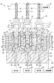
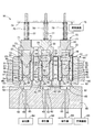
- FIG. 4 is a cross-sectional view of the disassembly and assembly apparatus in a state where a plunger is in contact with a plurality of body dies of a molding die unit. It is sectional drawing which shows the state which the plunger pressed several body type
- FIG. 1 shows a schematic structure of an entire molding apparatus to which the present invention is applied.
- the molding apparatus 10 press-molds a glass preform 95 (see FIG. 8) to produce a glass lens 90 (see FIG. 8), which is an optical element made of glass.
- the molding apparatus 10 includes a supply unit 11, a heating unit 12, a pressing unit 13, a slow cooling unit 14, an unloading unit 15, and a disassembly / assembly unit 16. Processing while doing. From the supply unit 11 to the take-out unit 15, the mold unit 17 (see FIG. 4) in the assembled state is transferred by a series of transfer lines.
- the disassembling and assembling apparatus 16 disassembles and assembles the molding die unit 17.
- the supply unit 11 is a part that receives the mold unit 17 assembled by the disassembly / assembly apparatus 16 and supplies the mold unit 17 onto the transfer line.
- the heating section 12 is a section that heats and softens the glass preform 95 to be molded.
- the press section 13 is a section where the softened glass preform 95 is press-formed by an upper mold 30 and a lower mold 40 (see FIG. 2 and subsequent figures).
- the slow cooling unit 14 is a part that cools the molding die unit 17 including the molded glass lens 90.
- the take-out part 15 is a part that takes out the cooled mold unit 17 from the transfer line.
- the disassembling and assembling apparatus 16 partially disassembles the molding die unit 17 to take out the molded glass lens 90, and sets a glass preform 95 to be molded next between the upper mold 30 and the lower mold 40 to mold. This is a part for assembling the mold unit 17.
- the transfer line from the supply unit 11 to the extraction unit 15 and the disassembly / assembly apparatus 16 are installed in a chamber (not shown), and are formed in a state where the inside of the chamber is filled with an inert gas and the oxygen concentration is set to a predetermined value or less. Processing can be performed.
- the mold unit 17 includes a plurality of molds 18 each including a body mold 20, an upper mold 30, and a lower mold 40. It is held by the holder 50.
- one mold holder 50 holds seven molds 18. That is, the molding unit 17 is constituted by one molding die holder 50 and seven molding dies 18. 2 and 3, one mold 18 is representatively shown, but the other molds 18 have the same structure.
- One glass lens 90 is molded by one molding die 18.
- the reference axis X shown in FIGS. 2 and 3 coincides with the optical axis of the glass lens 90 formed by the mold 18.
- the upper mold 30 and the lower mold 40 are pressed by sandwiching a glass preform 95 therebetween while being supported by the body mold 20 such that their respective central axes coincide with the reference axis X, thereby manufacturing a glass lens 90.
- the glass lens 90 is an aspheric lens, and has a concave surface 91 and a convex surface 92 on the front and back as lens surfaces, as shown in FIG.
- the molding die unit 17 is installed so that the reference axis X of each molding die 18 is oriented vertically.
- a direction along the reference axis X is defined as an up-down direction
- a direction perpendicular to the reference axis X is defined as a radial direction.
- the body mold 20, the upper mold 30, and the lower mold 40 constituting the molding die 18 are formed of a material having excellent heat resistance and durability so as not to be easily damaged or deteriorated by press working at a high temperature. Specifically, it is formed of a ceramic such as silicon carbide (SiC) or silicon nitride (Si 3 N 4 ), or a metal such as a cemented carbide. Similarly, the molding die holder 50 is formed of a material having excellent heat resistance and durability.
- the barrel mold 20 is a cylindrical body surrounding the reference axis X, and has a cylindrical outer surface having a constant outer diameter size.
- a mold guide hole 21 is formed inside the body mold 20.
- the mold guide hole 21 is vertically opened through the body mold 20 in the vertical direction.
- a part of the upper end side of the mold guide hole 21 is an upper mold support hole 22 having an enlarged inner diameter.
- An upper die regulating surface 23 extending in the radial direction of the body die 20 is formed at a lower end portion of the upper die support hole 22.
- a lower end surface 24 extending in the radial direction of the body die 20 is formed around the opening of the die guide hole 21.
- the upper mold regulating surface 23 is an annular surface facing upward, and the lower end surface 24 is an annular surface facing downward.
- a conical tapered surface 25 is formed in a part of the lower end side of the mold guide hole 21 so that the inner diameter decreases as the distance from the lower end surface 24 increases.
- the die guide hole 21 has a cylindrical inner surface with a constant inner diameter size except for the upper die support hole 22 and the tapered surface 25.
- the upper die 30 has a shaft portion 31 extending in the vertical direction, a flange-shaped large-diameter portion 32 located above the shaft portion 31, and a protruding portion 33 protruding upward from the large-diameter portion 32.
- the shaft portion 31 has a columnar shape centered on the reference axis X, and has a shaping surface 34 formed at a tip facing downward.
- the large diameter portion 32 is located coaxially with the shaft portion 31 and has a cylindrical shape having a larger diameter than the shaft portion 31.
- the protruding portion 33 is located coaxially with the shaft portion 31 and the large-diameter portion 32, and has a cylindrical shape having the same diameter as the shaft portion 31.
- the molding surface 34 is a convex surface having a shape corresponding to the concave surface 91 of the glass lens 90.
- An annular downward regulating surface 35 extending in the radial direction of the upper die 30 is formed at the boundary between the shaft portion 31 and the large diameter portion 32.
- the shaft portion 31 of the upper die 30 is inserted into the die guide hole 21 of the body die 20 from above, and is slidably guided in the vertical direction in this inserted state.
- the outer diameter of the shaft portion 31 corresponds to the inner diameter of the die guide hole 21 (excluding the upper die support hole 22 and the tapered surface 25), and the outer diameter of the large diameter portion 32 corresponds to the inner diameter of the upper die support hole 22.
- the radial clearance between the shaft portion 31 and the mold guide hole 21 is extremely small (for example, several ⁇ m), and the radial position and angle (parallelism with the reference axis X) of the upper mold 30 are precisely determined by the body mold 20.
- the upper mold 30 can be inserted into the body mold 20 up to a position where the regulating surface 35 contacts the upper mold regulating surface 23, and the movement of the upper mold 30 below the position is regulated (FIG. 4). To FIG. 8). In this state, the protruding portion 33 protrudes upward from the trunk mold 20.
- the lower mold 40 has a shaft portion 41 extending vertically and a flange-shaped large-diameter portion 42 located below the shaft portion 41.
- the shaft portion 41 has a columnar shape centered on the reference axis X, and has a molding surface 43 (see FIG. 2) formed on the tip side facing upward.
- the large-diameter portion 42 is coaxial with the shaft portion 41, has a larger diameter than the shaft portion 41, and has a columnar shape smaller in diameter than the outer diameter of the body mold 20.
- the molding surface 43 is a concave surface having a shape corresponding to the convex surface 92 of the glass lens 90, and a cylindrical portion 44 protruding upward is formed on the periphery of the molding surface 43 (see FIG. 2).
- the shaft 41 of the lower mold 40 is inserted into the mold guide hole 21 of the body mold 20 from below, and is guided slidably in the vertical direction in this inserted state.
- the outer diameter of the shaft portion 41 corresponds to the inner diameter of the die guide hole 21 (the portion excluding the upper die support hole 22 and the tapered surface 25).
- the radial clearance between the shaft portion 41 and the mold guide hole 21 is extremely small (for example, several ⁇ m), and the radial position and angle (parallelism with the reference axis X) of the lower mold 40 are precisely determined by the body mold 20.
- the lower mold 40 can be inserted into the body mold 20 up to a position where the regulating surface 45 contacts the lower end face 24, and the movement of the lower mold 40 above the position is regulated (see FIG. 4 to FIG. 4). 6).
- the large diameter portion 42 protrudes downward from the body mold 20.
- the outer diameter of the large-diameter portion 42 is smaller than the outer diameter of the body mold 20 by a predetermined amount, and in a state where the regulating surface 45 is in contact with the lower end surface 24, the regulating surface 45 is formed on the outer peripheral side of the lower end surface 24. There are annular regions that do not abut.
- the upper mold 30 and the lower mold 40 are combined with the body mold 20.
- a molding die 18 is formed.
- the molding surface 34 and the molding surface 43 face each other in the vertical direction.
- the molding die holder 50 has seven accommodation holes 51 penetrating vertically in a cylindrical body, and one molding die 18 can be inserted and held in each accommodation hole 51. All the seven receiving holes 51 have the same shape and dimensions.
- a body-shaped restricting portion 52 having a small opening diameter is formed so as to protrude annularly in the inner diameter direction.
- the accommodation hole 51 has a cylindrical inner surface having a constant inner diameter size, except for the location where the trunk-shaped regulating portion 52 is formed.
- a body mold facing surface 53 As the upper surface of the body mold regulating portion 52, a body mold facing surface 53 extending in the radial direction of the mold holder 50 is formed.
- the trunk-shaped facing surface 53 is an annular surface facing upward.
- the body molds 20 of the respective molds 18 are slidably inserted into the accommodation holes 51 of the mold holder 50 from above in the vertical direction.
- the radial clearance between the housing hole 51 and the body mold 20 is greater than the radial clearance of the upper mold 30 (shaft 31) and the lower mold 40 (shaft 41) with respect to the body mold 20 (mold guide hole 21). Large (for example, several tens of ⁇ m).
- the lower end surface 24 (the outer peripheral area where the regulating surface 45 of the lower mold 40 does not abut) can be inserted into the housing hole 51 to a position where it abuts the body mold opposing surface 53.
- the movement of the trunk die 20 below the position is restricted (see FIGS. 6 to 8). With the lower end surface 24 in contact with the trunk-type facing surface 53, the upper end of the trunk die 20 slightly projects upward from the housing hole 51.
- the body mold restricting portion 52 of the mold holder 50 has an inner diameter that does not allow the body 20 to pass downward and allows the large diameter portion 42 of the lower mold 40 to pass in the vertical direction. That is, the outer diameter of the trunk die 20 is larger than the inner diameter of the trunk die restriction part 52, and the outer diameter of the large diameter part 42 is smaller than the inner diameter of the trunk die restriction part 52.
- the clearance in the radial direction between the trunk mold regulating portion 52 and the large diameter portion 42 is larger than the clearance between the mold guide hole 21 and the shaft portion 41 (for example, several tens ⁇ m).
- the lower mold 40 is not affected by the abutment between the outer surface of the large-diameter portion 42 and the inner surface of the torso mold restricting portion 52 in a state where the shaft portion 41 is inserted into the mold guide hole 21. It can be positioned radially.
- the large-diameter portion 42 is thicker in the vertical direction than the trunk-shaped regulating portion 52. Therefore, as shown in FIGS. 4 to 6, in a state where the lower surface position of the lower mold 40 (large-diameter portion 42) coincides with (becomes flush with) the lower surface position of the molding die holder 50 (body mold regulating portion 52).
- the regulating surface 45 is located above the trunk-shaped facing surface 53.
- the seven accommodation holes 51 are arranged at equal intervals with other adjacent accommodation holes 51. That is, the seven accommodation holes 51 are arranged such that the respective central axes (the reference axes X in the mold 18) are located at the vertices and the center of the regular hexagon when viewed from above.
- the disassembling and assembling apparatus 16 includes a pedestal 60, a plunger (pressing means) 70 located above the pedestal 60, and a fixing mechanism (fixing means) 80.
- the pedestal 60 can be moved up and down by a lifting mechanism 65.
- the plunger 70 is suspended and supported via a plurality of compression springs (biasing means) 76 on an upper elevating unit (elevating unit) 74 that can be moved up and down by an elevating mechanism 75.
- the elevating mechanism 65 and the elevating mechanism 75 are composed of well-known pistons, cylinders, actuators, and the like, and detailed illustration and description are omitted.
- the fixing mechanism 80 holds the mold holder 50 from the side and fixedly supports it.
- the pedestal 60 has a mounting surface 61 on which all the lower dies 40 constituting the molding die unit 17 can be mounted at the same time.
- a plurality of suction recesses 62 are formed on the mounting surface 61 in a positional relationship corresponding to each lower die 40.
- FIGS. 4 to 8 show three suction recesses 62 located on the same cross section. However, seven suction recesses 62 are provided corresponding to the seven lower dies 40 of each mold unit 17.
- the mounting surface 61 has a planar shape extending in the horizontal direction, except for the location where each suction recess 62 is formed.
- each suction concave portion 62 The size of the opening of each suction concave portion 62 is smaller than the lower surface of the large-diameter portion 42 of the lower die 40, and when the lower die 40 is placed at a predetermined position on the mounting surface 61, each suction concave portion 62 Covered by mold 40.
- a suction passage 63 is individually connected to each suction recess 62.
- Each suction passage 63 is individually connected to a suction source 64 composed of a vacuum pump. Seven suction passages 63 and seven suction sources 64 are provided corresponding to the seven suction recesses 62, respectively. When each suction source 64 is driven, a suction force can be applied to each suction recess 62 via each suction passage 63. That is, the suction recesses 62, the suction passages 63, and the suction sources 64 constitute suction means for holding the lower surfaces of the plurality of lower dies 40 on the mounting surface 61 of the pedestal 60.
- the plunger 70 has a number and arrangement of pressing portions 71 corresponding to all the trunk dies 20 constituting the molding die unit 17.
- FIGS. 4 to 8 show three pressing portions 71 located on the same cross section. However, seven pressing portions 71 are provided corresponding to the seven trunk dies 20 of each mold unit 17.
- Each pressing portion 71 has a downward annular contact surface 72 at the lower end capable of contacting the upper end surface of the body mold 20.
- a concave portion 73 that opens downward is formed on the inside surrounded by the contact surface 72.
- the contact surface 72 has a larger radial width than the upper end surface of the body mold 20. Therefore, in a state of being in contact with the upper end surface of the body mold 20 (FIGS. 5 to 8), a part of the contact surface 72 on the inner diameter side is located on the inner diameter side with respect to the inner surface of the upper die support hole 22, and A part on the outer diameter side of the contact surface 72 is located on the outer diameter side with respect to the outer surface of the body mold 20.
- the protrusion 33 of the upper mold 30 can enter the recess 73 (see FIGS. 5 to 8). A large radial and vertical clearance is secured between the recess 73 and the protrusion 33, and the protrusion 33 enters without contacting the inner surface of the recess 73.
- a plurality of guide shafts 77 project upward from the plunger 70.
- Each guide shaft 77 is inserted slidably in a vertical direction into a guide hole formed in the upper elevating section 74.
- the plunger 70 is supported so as to move straight in the vertical direction.
- Each guide shaft 77 is inserted through a compression spring 76.
- Each compression spring 76 has an upper end connected to the upper elevating section 74 and a lower end connected to the plunger 70.
- the fixing mechanism 80 includes a clamp portion (a portion shown in FIGS. 4 to 8) that sandwiches the outer peripheral portion of the molding die holder 50, and a pressing portion (not shown) that applies a force for pressing the clamp portion to the molding die holder 50. It has.
- the clamp unit can fix and fix the orientation of the molding unit 17 with high precision so that the reference axis X of each molding die 18 is oriented in the vertical direction (vertical direction) while the molding die holder 50 is held therebetween. it can.
- the molding apparatus 10 includes a control circuit (not shown) that controls the overall control.
- the control circuit controls the operations of the suction source 64 and the lifting / lowering mechanisms 65 and 75 in the disassembly / assembly apparatus 16 in addition to the operation control of each unit from the supply unit 11 to the removal unit 15.
- the following operations in the disassembly / assembly apparatus 16 are executed under the control of the control circuit.
- each of the molding dies 18 of the molding unit 17 is connected to the shaft part 31 of the upper mold 30 and the shaft part 41 of the lower mold 40 by the mold guide holes 21 of the body mold 20. It is inserted in. More specifically, the molding die unit 17 is mounted so that the lower surfaces of the plurality of lower dies 40 and the lower surface of the molding die holder 50 are substantially flush with each other.
- Reference numeral 50 has the positional relationship shown in FIGS.
- the regulating surface 45 of the lower die 40 is located above the trunk-type facing surface 53 of the molding die holder 50 due to the difference in the vertical thickness between the large-diameter portion 42 and the trunk-type regulating portion 52.
- the lower end surface 24 of the body mold 20 is in contact with the regulating surface 45 and is separated upward from the body mold facing surface 53.
- the glass preform 95 (see FIG. 8) is sandwiched between the molding surface 34 of the upper mold 30 and the molding surface 43 of the lower mold 40 in each molding die 18.
- the upper mold 30 projects upward from the position shown in FIGS. 4 and 5 with respect to the body mold 20 according to the thickness of the glass preform 95.
- the glass preform 95 is heated to a temperature higher than the glass transition temperature to soften the glass preform 95.
- the upper mold 30 of each mold 18 is pressed downward using a piston or the like (not shown).
- the protruding part 33 protruding upward from the trunk die 20 or the large diameter part 32 located around the protruding part 33 is pressed.
- the molding surface 34 approaches the molding surface 43 of the lower mold 40 and presses the glass preform 95 to form the glass lens 90.
- the regulating surface 45 of the lower die 40 is in contact with the lower end surface 24 of the body die 20, and the lower end surface 24 of the body die 20 is separated from the body die facing surface 53 of the molding die holder 50 (see FIG. 4 and FIG. 4).
- the mold holder 50 is not involved in the vertical position management of each mold 18 (see FIG. 5). Thereby, each of the plurality of molds 18 can individually perform the press working with high accuracy without being interfered by the other molds 18 and the mold holder 50.
- the upper mold 30 is pushed to a position where the regulating surface 35 contacts the upper mold regulating surface 23, and each of the molding dies 18 is in a state shown in FIGS.
- the pressurized mold unit 17 is cooled by the slow cooling unit 14, the take-out unit 15 takes out the mold unit 17 from the transfer line, and transfers it to the disassembly / assembly device 16.
- the disassembly and assembly of the mold 18 in the disassembly / assembly apparatus 16 will be described with reference to FIGS.
- the mold unit 17 transported to the disassembly / assembly device 16 is disposed between the pedestal 60 and the plunger 70 as shown in FIG.
- the mold unit 17 is mounted on the mounting surface 61 of the pedestal 60.
- the fixing mechanism 80 holds the mold holder 50 from the side to fix the position of the mold holder 50.
- the position of the mold unit 17 is determined so that the plurality of lower dies 40 close the plurality of suction recesses 62 on the mounting surface 61.
- the lower surface of the lower die 40 supported on the mounting surface 61 and the lower surface of the molding die holder 50 are substantially flush with each other, as in the process of the press unit 13 described above. Has become.
- the torso 20 of each of the forming dies 18 makes the lower end surface 24 abut on the regulating surface 45, and the lower end surface 24 becomes It is separated upward from the facing surface 53.
- each mold 18 is in a state in which the body mold 20 and the upper mold 30 are projected upward from the mold holder 50 by a predetermined amount.
- the plunger 70 is at a retracted position away from the molding die unit 17 and has a positional relationship in which the plurality of pressing portions 71 vertically face the plurality of molding dies 18.
- the contact surface 72 of each pressing portion 71 faces the upper end surface of each trunk die 20.
- the body die 20 can be moved downward with respect to the molding die holder 50 to a regulation position (FIG. 6) where the lower end surface 24 abuts on the body mold opposing surface 53, and movement below the regulation position is restricted by the body mold restriction. It is regulated by the unit 52.
- each plunger 20 is pressed by the plunger 70 by using the urging force of the compression spring 76, it is possible to reliably operate with an appropriate load while absorbing variations in the positions and movements of the plurality of trunk dies 20. . If the plunger 70 and the upper elevating part 74 are directly connected by a rigid body and moved integrally, an excessive load acts on a specific mold 18 without the plunger 70 having such a variation absorbing function. There is a possibility that it will.
- the upper mold 30 also moves downward along with the body mold 20.
- a part on the inner diameter side of the contact surface 72 of the plunger 70 is located above the large diameter portion 32 (partially closes the opening of the upper die support hole 22). Therefore, even when the upper mold 30 does not descend with the body mold 20 due to its own weight, detachment of the upper mold 30 upward from the body mold 20 is limited by the contact surface 72 of the plunger 70.
- each body mold 20 moves downward in each accommodation hole 51, the lower end surface 24 presses the regulating surface 45, and each lower mold 40 is also moved downward with respect to the mold holder 50.
- the pedestal 60 is also pushed downward through each lower die 40, and the mounting surface 61 is slightly separated from the lower surface of the molding die holder 50 (see FIG. 6).
- each forming mold 18 and the pedestal 60 move downward by the pressing force (biasing force) from the plunger 70 side.
- each of the body dies 20 can no longer move downward with respect to the molding die holder 50.
- Each upper die 30 is further restricted from moving downward with respect to the molding die holder 50 by the contact of the restriction surface 35 with the upper die restriction surface 23 of the body die 20.
- the lifting mechanism 65 is driven to move the pedestal 60 downward.
- the suction source 64 is driven to hold each lower mold 40 on the pedestal 60 by suction.
- the lower mold 40 allows the large-diameter portion 42 to pass through the inside of the body mold regulating portion 52 in the vertical direction, and is not restricted by the downward movement of the mold holder 50. Shape. Therefore, when the pedestal 60 moves downward, each of the lower dies 40 placed on the mounting surface 61 follows the pedestal 60 and moves downward with respect to the molding die holder 50 and the body die 20 (FIG. 7). reference). The glass lens 90 moves downward with each lower mold 40.
- each of the lower dies 40 Since the clearance between the shaft portion 41 of each lower die 40 and the die guide hole 21 of each trunk die 20 is extremely small, each of the lower dies 40 has a smaller weight than the trunk die 20 by its own weight depending on the magnitude of the sliding resistance. May be difficult to move downward.
- each suction source 64 By driving each suction source 64 to apply a suction force from each suction recess 62 to each lower mold 40, each lower mold 40 is reliably moved downward along with the pedestal 60 even when sliding resistance is large. Then, it can be separated from the mold guide hole 21.
- the lower mold 40 did not move downward with the pedestal 60 for some reason, or the lower mold 40 was largely displaced in the radial direction on the mounting surface 61. In this case, the lower mold 40 does not completely close the corresponding suction recess 62, and outside air flows into the suction recess 62. Then, as compared with the suction state in which the suction concave portion 62 is completely closed by the lower mold 40, the pressure in the suction concave portion 62 and the suction passage 63 increases (approaches the outside air pressure). Therefore, based on the pressure change in the suction path, it is possible to confirm whether or not each of the lower dies 40 is appropriately moving downward along with the pedestal 60.
- Each of a plurality of suction paths from the suction recess 62 to the suction source 64 is provided with a pressure sensor capable of detecting such a pressure change. If a pressure increase equal to or more than a predetermined value is detected in any of the suction paths, it is considered that some error has occurred in the operation of pulling out each lower mold 40 from each body mold 20 and the mold holder 50, and the pedestal 60 Can be stopped or an alarm can be issued.
- the suction means from the suction concave portion 62 to the suction source 64 is configured to individually suction the plurality of lower dies 40, it is possible to reliably detect an error in the pull-out operation in the specific lower die 40.
- each lower die 40 is completely detached from the body die 20 and the molding die holder 50 as shown in FIG. As a result, the molded glass lens 90 placed on each lower mold 40 is exposed, and the glass lens 90 is taken out and carried out. Thus, one cycle of processing in the molding apparatus 10 is completed.
- the glass preform 95 to be molded next is placed on each lower mold 40 (see FIG. 8). Then, the pedestal 60 is moved upward by the lifting mechanism 65. Further, the lifting mechanism 75 is driven to move (up) the plunger 70 to the retracted position shown in FIG.
- each lower die 40 enters the body die 20 and the molding die holder 50. At this time, even if the radial position of the shaft portion 41 with respect to the mold guide hole 21 does not completely match, the tip of the shaft portion 41 contacts the tapered surface 25, and the tapered surface 25 guides the shaft portion 41 as a guide surface. As a result, it can be reliably guided into the mold guide hole 21. In other words, the lower mold 40 can be aligned with the body mold 20 by the tapered surface 25. As described above, although the radial clearance between the shaft portion 41 and the mold guide hole 21 is extremely small, each of the lower dies 40 can be smoothly assembled by the structure.
- the pedestal 60 is raised to a position where the lower surface of each lower die 40 is flush with the lower surface of the molding die holder 50.
- the shaft portion 41 of each lower die 40 enters the die guide hole 21, and the regulating surface 45 contacts the lower end surface 24 of the body die 20, and the assembly of each forming die 18 is completed.
- the body mold 20, the lower mold 40, and the mold holder 50 have the positional relationship shown in FIGS.
- the upper mold 30 is pushed upward from the position of FIGS. 4 and 5 with respect to the body mold 20 by sandwiching the glass preform 95 between the upper mold 30 and the lower mold 40, and is regulated with respect to the upper mold regulating surface 23.
- the surface 35 separates upward.
- the amount by which the upper die 30 is pushed up is the amount of downward movement of the upper die 30 during the press forming in the press section 13 described above.
- the mold unit 17 in the disassembly / assembly apparatus 16 is in an assembly completed state.
- the molding unit 17 in the assembled state is conveyed to the supply unit 11 and is subjected to molding in the above-described series of steps.
- the disassembling and assembling of the plurality of molding dies 18 can be performed mechanically and collectively without manual work, and the work efficiency is excellent.
- disassembly and assembly are performed only by the vertical movement of the pedestal 60 and the plunger 70, so that a mechanical structure can be obtained simply and at low cost.
- each molding die 18 is disassembled, so that it is expensive to move the die in the die removing direction while precisely grasping the die. No complicated mechanism is required.
- each lower die 40 by assisting the pulling out of each lower die 40 by suctioning the mounting surface 61 of the pedestal 60, the molding die 18 for molding a glass lens, in which the clearance between the trunk die 20 and the lower die 40 is extremely small, is ensured.
- Can be decomposed into The holding of each lower mold 40 by suction can be realized with a low cost and simple structure, and also contributes to the improvement of the stability of each lower mold 40.
- a trunk die regulating portion 52 is provided in each of the accommodation holes 51 of the molding die holder 50.
- the body mold restricting portion 52 allows the lower mold 40 of each of the molding dies 18 to pass in the vertical direction, and restricts the passage of the body mold 20 downward. With the body mold restricting portion 52, after dividing each body mold 20 and each upper mold 30 on the molding mold holder 50 side, the lower mold 40 is separated downward as the pedestal 60 descends. realizable. For example, as a difference from the present embodiment, in a mode in which a plurality of body dies 20 detached from the molding die holder 50 are individually held when each molding die 18 is disassembled, a fixing mechanism is required by the number of molding dies 18.
- a body mold regulating portion 52 for regulating the movement of each body mold 20 is provided in advance in the mold holder 50, and the mold holder 50 is held by one fixing mechanism 80. This can simplify the structure and save time and effort.
- the body die regulating portion 52 itself is formed by molding using a die structure that is divided in the reference axis X direction, cutting by partially changing the inner diameter of a pilot hole provided in the molding die holder 50, or the like. And a shape that can be obtained at low cost.
- the disassembling and assembling apparatus for a mold according to the present embodiment can efficiently and reliably disassemble and assemble a plurality of molds with an inexpensive configuration.
- the present invention is not limited to the above embodiments, and various changes can be made within the gist of the invention.
- the molding unit 17 of the above embodiment includes seven molding dies 18, but the number of molding dies included in one molding unit is not limited to seven and can be arbitrarily selected.
- the seven molds 18 are arranged on the mold holder 50 at equal intervals. This configuration is less likely to cause load imbalance among a plurality of molds during press working or disassembly of the molds, and is excellent in weight balance and the like. However, it is also possible to select a configuration in which a plurality of molds are arranged at unequal intervals.
- the mold holder 50 of the above embodiment has a columnar shape
- a mold holder having a shape other than the columnar shape may be employed.
- the condition that the insertion of the trunk die into the die guide hole is regulated and the condition that the lower die has a large diameter portion that can pass through the inside of the trunk die regulating portion of the molding die holder is satisfied.
- the shape and the like can be arbitrarily selected.
- the regulating surface 45 of the large-diameter portion 42 of the lower die 40 is in contact with the lower end surface 24 of the trunk die 20.
- a lower die supporting hole (a hole having a shape obtained by turning the upper die supporting hole 22 upside down) having an increased inner diameter is provided at the lower end side of the die guide hole 21 of the trunk die 20. It is also possible to adopt a configuration in which the regulating surface 45 of the large-diameter portion 42 abuts against the bottom surface of the supporting hole (a surface having a shape obtained by turning the upper mold regulating surface 23 upside down).
- the movement of the upper die relative to the body die below a predetermined position is regulated, and the upper die is placed so as not to hinder the pressing by the pressing means (plunger 70) from above.
- the shape and the like can be arbitrarily selected as long as at least a part of the end face is exposed.
- the upper die supporting hole 22 and the upper die regulating surface 23 are formed in the die guide hole 21 as a portion that restricts the downward movement of the upper die 30 with respect to the trunk die 20.
- the upper die support hole 22 is not provided, and the die guide hole 21 having a constant inner diameter continues to the upper end of the trunk die 20.
- the molding apparatus 10 of the above embodiment is for manufacturing a glass lens 90, but the present invention can also be applied to a molding apparatus for manufacturing a glass optical element (for example, a prism or the like) other than a lens.
- a glass optical element for example, a prism or the like
- a plurality of molds can be efficiently and reliably disassembled and assembled with an inexpensive configuration, and it is particularly useful for a molding apparatus that requires efficient production of a large number of glass optical elements.
- Molding device 16 Disassembly device 17: Mold unit 18: Mold 20: Body mold 21: Mold guide hole 24: Lower end surface 25: Tapered surface 30: Upper mold 31: Shaft portion 32: Large diameter portion 34: Molding surface 35: Regulating surface 40: Lower mold 41: Shaft 42: Large diameter portion 43: Molding surface 45: Regulating surface 50: Molding die holder 51: Housing hole 52: Trunk die regulating portion 53: Trunk die opposing surface 60: Pedestal 61: Mounting surface 62: Suction recess (suction means) 63: suction passage (suction means) 64: suction source (suction means) 65: lifting mechanism 70: plunger (pressing means) 71: Pressing portion 72: Contact surface 73: Recess 74: Upper elevating portion (elevating portion) 75: lifting mechanism 76: compression spring (biasing means) 80: Fixing mechanism (fixing means) 90: Glass lens (glass optical element) 95: Glass preform
Landscapes
- Engineering & Computer Science (AREA)
- Chemical & Material Sciences (AREA)
- Manufacturing & Machinery (AREA)
- Materials Engineering (AREA)
- Organic Chemistry (AREA)
- Moulds For Moulding Plastics Or The Like (AREA)
Abstract
本発明は、安価な構成で効率良く確実に複数の成形型の分解組立を行える成形型の分解組立装置を提供することを目的とする。本発明の成形型の分解組立装置において、成形型ホルダの複数の収容孔に複数の成形型を挿入し、各成形型が胴型の型ガイド孔に上下から挿入される上型及び下型を備え、下型は型ガイド孔への挿入規制を受ける大径部を有する。成形型ホルダは各収容孔内に突出する環状の胴型規制部を有し、胴型規制部は、胴型の下端面に当接して下方への胴型の移動を規制し、且つ下型の大径部の通過を許す。固定手段により成形型ホルダを固定した状態で、押圧手段によって複数の胴型を上方から下方に押圧して、胴型規制部によって各胴型の下端面が下方への移動規制を受ける状態にすると共に、複数の下型を下方から支持する台座を下方に移動させて、各下型を対応する型ガイド孔及び収容孔から下方に離脱させる。
Description
本発明は、プレス成形用の成形型の分解組立装置に関する。
に関する。
に関する。
プレス成形用の成形型として、胴型に挿入される上型と下型を備え、所定以上の温度に加熱した状態で上型と下型を接近させてガラス材料をプレスして、ガラスレンズ等のガラス製品を形成するものが知られている。プレス加工後に上型と下型を分離させて成形後のガラス製品を取り出し、次に加工するガラス材料を上型と下型の間に設置して再びプレス加工を行う、というサイクルで順次製造を実行する。
被成形物としてガラスレンズのように両面に高度な精度が要求される光学素子を成形する成形型は、成形精度を確保するために、胴型に対する上型及び下型のクリアランスが極めて小さく設定されている。そのため、成形完了後の上型と下型の分解や、次に成形を行う際の胴型への上型や下型の組み付けは、互いの中心軸を精密に位置合わせした上で、ブレや傾きを生じさせずに軸方向へ移動させる必要がある。こうした成形型の分解や組み立ての作業を、上型や下型を機械的に保持しながら移動させる分解組立装置で行わせるには、非常に高度な動作精度が要求され、高価な装置を要することになる。そのため、ガラス製光学素子用の成形型の分解や組み立ては手作業で行う場合が多かった。特許文献1では、こうした成形型の分解や組み立てを安価且つ容易に機械化する技術が提案されている。
ガラス製光学素子を大量生産する成形装置では、製造効率向上のために、複数の成形型を共通の保持部材に保持させて搬送し、加熱、プレス、冷却等の各工程を複数の成形型に対してまとめて実行するものが実用化されている。このタイプの成形装置では、先に述べた上型と下型の分解及び組み立ての作業に加えて、保持部材に対する各成形型の着脱作業も行う必要があり、これらを効率化したいという要求があった。特に、手作業によらずに機械化された分解組立装置が望まれている。
本発明はかかる問題点に鑑みてなされたものであり、安価な構成で効率良く確実に複数の成形型の分解組立を行える成形型の分解組立装置を提供することを目的とする。
本発明は、上下方向に貫通する複数の収容孔を有する成形型ホルダにより複数の成形型を保持して、複数の成形型によって複数のガラス製光学素子をまとめてプレス成形する成形装置における、成形型の分解組立装置に関するものである。各成形型は胴型と上型と下型とを有する。胴型は、上下方向に貫通する型ガイド孔を有する。上型は、上方から型ガイド孔に挿入されて、所定の挿入位置で胴型に対する下方への移動を規制される。下型は、下方から型ガイド孔に挿入される軸部と、該軸部よりも大径且つ胴型の外径よりも小径で型ガイド孔に対する挿入を規制される大径部とを有する。胴型の型ガイド孔内で上型と下型の接近によりガラス製光学素子をプレス成形する。成形型ホルダは、複数の収容孔内にそれぞれ環状に突設される胴型規制部を有し、胴型規制部は、胴型の下端面の当接により該胴型の下方への移動を規制し、且つ下型の大径部の上下方向への通過を許す。分解組立装置は、成形型ホルダを固定する固定手段と、それぞれが上下方向に移動可能な押圧手段及び台座とを備える。押圧手段は、固定手段により成形型ホルダが固定された状態で複数の胴型を上方から下方に押圧して、胴型規制部によってそれぞれの胴型の下端面が下方への移動規制を受ける状態にする。台座は、固定手段により成形型ホルダが固定された状態で複数の下型を下方から支持し、下方へ移動して、複数の下型を対応する型ガイド孔及び収容孔から下方に離脱させる。
この本発明の成形型の分解組立装置では、固定手段により成形型ホルダを保持した状態で、押圧手段による複数の胴型に対する上方からの押圧と、複数の下型を支持する台座の下方への移動とによって、下型を取り外すことができる。また、台座を上方に移動させて、複数の下型を再び組み付けることができる。複数の胴型及び上型は、下方に離脱した各下型による支えがなくなった状態でも、収容孔内に設けた胴型規制部によって、成形型ホルダ側に継続して保持される。従って、それぞれの成形型の分解と組み立てを効率及び精度良く行うことが可能である。また、押圧手段や台座は上下方向に動作するシンプルなものであるため、複雑で高価な装置を要さない。
胴型規制部よりも下型の大径部の方が上下方向の厚さが大きく、プレス成形を行うとき、複数の下型の下面と成形型ホルダの下面が略面一で支持され、複数の下型のそれぞれの大径部が対応する胴型の下端面に当接し、且つ複数の胴型のそれぞれの下端面が対応する胴型規制部から上方に離間するようにすることが好ましい。これにより、プレス成形時には、成形型ホルダによる干渉を受けずに、高い精度で胴型と下型の相対位置を定めることができる。
複数の下型の下面を台座に吸引する吸引手段を有し、台座の下方への移動によって複数の下型を対応する型ガイド孔及び収容孔から下方に離脱させるときに、吸引手段を用いて台座に複数の下型を吸引保持することが好ましい。これにより、それぞれの成形型において、胴型の型ガイド孔と下型の軸部との間のクリアランスが極めて小さく摺動抵抗が大きくなりやすい場合でも、型ガイド孔に対する下型の軸部の離脱を確実に行わせることができる。
押圧手段は、台座とは独立して上下方向に移動可能な昇降部に対して付勢手段を介して支持されており、昇降部が下方に移動して押圧手段が複数の胴型に当接したとき、付勢手段によって押圧手段が下方に押圧付勢されるようにしてもよい。これにより、複数の胴型の位置や移動のばらつきを吸収して、適切な負荷で各胴型を押圧することができる。
複数の胴型はそれぞれ型ガイド孔の下端側の一部に、下端面から離れて上方に進むにつれて内径を小さくするテーパ面を有することが好ましい。これにより、それぞれの成形型において、胴型の型ガイド孔と下型の軸部との間のクリアランスが極めて小さい場合でも、分解後の各下型の軸部を対応する型ガイド孔内に再度挿入させやすくなる。
以上の本発明の成形型の分解組立装置によれば、安価な構成で効率良く確実に複数の成形型の分解組立を行うことができる。
図1は、本発明を適用した成形装置全体の概略構造を示している。本実施形態の成形装置10は、ガラスプリフォーム95(図8参照)をプレス成形してガラス製の光学素子であるガラスレンズ90(図8参照)を製造するものである。図1に示すように、成形装置10は、供給部11、加熱部12、プレス部13、徐冷部14、取出部15、分解組立装置16を備えており、成形型ユニット17を順次移送しながら加工を行う。供給部11から取出部15までは、組立状態の成形型ユニット17(図4参照)を一連の移送ラインで移送する。分解組立装置16では、成形型ユニット17の分解と組み立てを行う。
より詳しくは、供給部11は、分解組立装置16で組み立てられた成形型ユニット17を受け取って移送ライン上に供給する部分である。加熱部12は、成形対象であるガラスプリフォーム95を加熱して軟化させる部分である。プレス部13は、軟化したガラスプリフォーム95を後述する上型30と下型40(図2以降参照)によってプレス成形する部分である。徐冷部14は、成形後のガラスレンズ90を含む成形型ユニット17を冷却する部分である。取出部15は、冷却後の成形型ユニット17を移送ラインから取り出す部分である。分解組立装置16は、成形型ユニット17を部分的に分解して成形後のガラスレンズ90を取り出すと共に、次に成形するガラスプリフォーム95を上型30と下型40の間にセットして成形型ユニット17を組み立てる部分である。供給部11から取出部15までの移送ラインや分解組立装置16は、図示を省略するチャンバー内に設置されており、チャンバー内を不活性ガスで満たして酸素濃度を所定値以下にした状態で成形加工を行うことができる。
図2から図8に示すように、成形型ユニット17は、各々が胴型20と上型30と下型40で構成される成形型18を複数備え、この複数個の成形型18を成形型ホルダ50によって保持したものである。本実施形態では、1つの成形型ホルダ50が7つの成形型18を保持する。すなわち、成形型ユニット17は、1つの成形型ホルダ50と7つの成形型18により構成されている。図2及び図3では1つの成形型18を代表的に示しているが、他の成形型18も同じ構造になっている。
1つの成形型18で1つのガラスレンズ90が成形される。図2及び図3に示す基準軸Xは、成形型18により成形されるガラスレンズ90の光軸に一致するものである。上型30と下型40は、それぞれの中心軸が基準軸Xと一致するように胴型20に支持された状態で、ガラスプリフォーム95を間に挟んでプレスしてガラスレンズ90を製造する。ガラスレンズ90は非球面レンズであり、図8に示すように、レンズ面として凹面91と凸面92を表裏に有する。
成形装置10における供給部11から取出部15までの移送ラインと分解組立装置16では、各成形型18における基準軸Xが上下方向に向くようにして、成形型ユニット17が設置される。以下の説明では、基準軸Xに沿う方向を上下方向とし、基準軸Xに対して垂直な方向を径方向とする。
成形型18を構成する胴型20、上型30、下型40は、高温下でのプレス加工における破損や劣化が生じにくいように、耐熱性及び耐久性に優れる材質で形成されている。具体的には、炭化ケイ素(SiC)や窒化ケイ素(Si3N4)のようなセラミックス、あるいは超硬合金のような金属で形成されている。また、成形型ホルダ50も同様に、耐熱性及び耐久性に優れる材質で形成されている。
胴型20は、基準軸Xを囲む円筒状体であり、外径サイズが一定の円筒状の外面を有している。胴型20の内部には型ガイド孔21が形成されている。型ガイド孔21は、胴型20を上下方向に貫通して上下に開口している。型ガイド孔21の上端側の一部は、内径を拡大した上型支持孔22になっている。上型支持孔22の下端部分には、胴型20の径方向に延びる上型規制面23が形成されている。胴型20の下端には、型ガイド孔21の開口部分の周囲に、胴型20の径方向に延びる下端面24が形成されている。上型規制面23は上方を向く環状の面であり、下端面24は下方を向く環状の面である。また、型ガイド孔21の下端側の一部には、下端面24から離れて上方に進むにつれて内径を小さくする円錐状のテーパ面25が形成されている。型ガイド孔21は、上型支持孔22及びテーパ面25の箇所を除いて、内径サイズが一定の円筒状の内面を有している。
上型30は、上下方向に伸びる軸部31と、軸部31の上部に位置する鍔状の大径部32と、大径部32から上方に突出する突出部33とを有する。軸部31は基準軸Xを中心とする円柱形状をなし、下方を向く先端に成形面34が形成されている。大径部32は、軸部31と同軸上に位置し、軸部31よりも大径の円柱形状である。突出部33は、軸部31及び大径部32と同軸上に位置し、軸部31と同じ径の円柱形状である。成形面34は、ガラスレンズ90の凹面91に対応する形状の凸状の面である。軸部31と大径部32の境界部分には、上型30の径方向に延びる、環状で下向きの規制面35が形成されている。
上型30の軸部31は、胴型20の型ガイド孔21に対して上方から挿入され、この挿入状態で上下方向へ摺動可能に案内される。軸部31の外径が型ガイド孔21(上型支持孔22及びテーパ面25を除く部分)の内径に対応し、大径部32の外径が上型支持孔22の内径に対応する。軸部31と型ガイド孔21の間の径方向のクリアランスは極めて小さく(例えば数μm)、胴型20によって上型30の径方向位置及び角度(基準軸Xとの平行度)が精密に決められる。胴型20に対して上型30は、規制面35が上型規制面23に当接する位置まで挿入することができ、当該位置よりも下方への上型30の移動は規制される(図4から図8参照)。この状態で、突出部33が胴型20から上方に突出する。
下型40は、上下方向に伸びる軸部41と、軸部41の下部に位置する鍔状の大径部42とを有する。軸部41は基準軸Xを中心とする円柱形状をなし、上方を向く先端側に成形面43(図2参照)が形成されている。大径部42は、軸部41と同軸上に位置し、軸部41よりも大径で、胴型20の外径よりも小径の円柱形状である。成形面43は、ガラスレンズ90の凸面92に対応する形状の凹状の面であり、成形面43の周縁には上方に突出する円筒部44が形成されている(図2参照)。なお、図3から図8の断面では、成形面43と円筒部44の図示を省略している。軸部41と大径部42の境界部分には、下型40の径方向に延びる、環状で上向きの規制面45が形成されている。
下型40の軸部41は、胴型20の型ガイド孔21に対して下方から挿入され、この挿入状態で上下方向へ摺動可能に案内される。軸部41の外径が型ガイド孔21(上型支持孔22及びテーパ面25を除く部分)の内径に対応する。軸部41と型ガイド孔21の間の径方向のクリアランスは極めて小さく(例えば数μm)、胴型20によって下型40の径方向位置及び角度(基準軸Xとの平行度)が精密に決められる。胴型20に対して下型40は、規制面45が下端面24に当接する位置まで挿入することができ、当該位置よりも上方への下型40の移動は規制される(図4から図6参照)。この状態で、大径部42が胴型20から下方に突出する。大径部42の外径は胴型20の外径よりも所定量小さく、規制面45が下端面24に当接する状態で、下端面24の外径側の周縁部には、規制面45が当接しない環状の領域が存在する。
型ガイド孔21に対して上方から軸部31を挿入し、型ガイド孔21に対して下方から軸部41を挿入することにより、胴型20に対して上型30と下型40が組み合わされて成形型18が構成される。型ガイド孔21内に軸部31と軸部41を挿入した状態で、成形面34と成形面43が上下方向に対向する。
成形型ホルダ50は、円柱状の胴体内に、上下方向へ貫通する7つの収容孔51を有しており、各収容孔51内に1つの成形型18を挿入保持可能である。7つの収容孔51は全て同じ形状及び寸法である。収容孔51の下端側には、内径方向へ環状に突設されて開口径を小さくした胴型規制部52が形成されている。収容孔51は、胴型規制部52の形成箇所を除いて、内径サイズが一定の円筒状の内面を有している。胴型規制部52の上面として、成形型ホルダ50の径方向に延びる胴型対向面53が形成されている。胴型対向面53は、上方を向く環状の面である。
それぞれの成形型18における胴型20は、成形型ホルダ50の収容孔51に対して上方から上下方向へ摺動可能に挿入される。収容孔51と胴型20の間の径方向のクリアランスは、胴型20(型ガイド孔21)に対する上型30(軸部31)及び下型40(軸部41)の径方向のクリアランスよりも大きい(例えば数十μm)。胴型20単体としては、下端面24(下型40の規制面45が当接しない外径側の周縁領域)が胴型対向面53に当接する位置まで収容孔51に挿入することができ、当該位置よりも下方への胴型20の移動は規制される(図6から図8参照)。下端面24が胴型対向面53に当接する状態で、胴型20の上端が収容孔51から上方へ僅かに突出する。
成形型ホルダ50の胴型規制部52は、下方への胴型20の通過を許さず、且つ上下方向への下型40の大径部42の通過を許す内径を備えている。すなわち、胴型20の外径は胴型規制部52の内径よりも大きく、大径部42の外径は胴型規制部52の内径よりも小さい。胴型規制部52と大径部42の間の径方向のクリアランスは、型ガイド孔21と軸部41の間のクリアランスよりも大きい(例えば数十μm)。従って、下型40は、軸部41が型ガイド孔21に挿入された状態で、大径部42の外面と胴型規制部52の内面の当接による干渉を受けることなく、胴型20によって径方向に位置決めすることができる。
大径部42は胴型規制部52よりも上下方向の厚みが大きい。そのため、図4から図6のように、下型40(大径部42)の下面位置が成形型ホルダ50(胴型規制部52)の下面位置と一致する(面一になる)状態では、規制面45が胴型対向面53よりも上方に位置する。
成形型ホルダ50を図1のように上面視すると、7つの収容孔51は隣接する他の収容孔51と互いに等間隔に配置されている。すなわち、7つの収容孔51は、上面視で正六角形の各頂点と中心に各々の中心軸(成形型18における基準軸X)が位置するように配置されている。
図4から図8に示すように、分解組立装置16は、台座60と、台座60の上方に位置するプランジャ(押圧手段)70と、固定機構(固定手段)80を備えている。台座60は昇降機構65によって上下に移動させることができる。プランジャ70は、昇降機構75によって上下に移動させることが可能な上方昇降部(昇降部)74に対して、複数の圧縮バネ(付勢手段)76を介して吊り下げて支持されている。昇降機構65と昇降機構75は、周知のピストンやシリンダやアクチュエータ等で構成されており、詳細の図示及び説明を省略する。固定機構80は、成形型ホルダ50を側方から保持して固定的に支持する。
台座60は、成形型ユニット17を構成する全ての下型40を同時に載置可能な載置面61を有する。載置面61上には、各下型40に対応する位置関係で複数の吸引凹部62が形成されている。図4から図8には、同一断面上に位置する3つの吸引凹部62が図示されているが、各成形型ユニット17の7つの下型40に対応して、7つの吸引凹部62を備える。載置面61は、各吸引凹部62の形成箇所を除いて、水平方向に延びる平面形状になっている。
各吸引凹部62の開口の大きさは、下型40における大径部42の下面よりも小さく、載置面61上の所定位置に下型40を載置した状態では、各吸引凹部62が下型40によって覆われる。各吸引凹部62には個別に吸引通路63が接続している。各吸引通路63は真空ポンプからなる吸引源64に個別に接続している。吸引通路63と吸引源64は、7つの吸引凹部62に対応してそれぞれ7つ設けられている。各吸引源64を駆動すると、各吸引通路63を経由して各吸引凹部62に吸引力を作用させることができる。すなわち、それぞれの吸引凹部62と吸引通路63と吸引源64により、複数の下型40の下面を台座60の載置面61上に吸引保持する吸引手段が構成されている。
プランジャ70は、成形型ユニット17を構成する全ての胴型20に対応する数と配置の押圧部71を有する。図4から図8には、同一断面上に位置する3つの押圧部71が図示されているが、各成形型ユニット17の7つの胴型20に対応して、7つの押圧部71を備える。各押圧部71は、胴型20の上端面に当接可能な下向きの環状の当接面72を下端に有する。当接面72に囲まれる内側に、下方に向けて開口する凹部73が形成されている。
当接面72は、胴型20の上端面よりも径方向の幅が大きい。そのため、胴型20の上端面に当接した状態(図5から図8)で、当接面72の内径側の一部が上型支持孔22の内面よりも内径側に位置し、且つ当接面72の外径側の一部が胴型20の外面よりも外径側に位置する。凹部73内に上型30の突出部33が進入可能である(図5から図8参照)。凹部73と突出部33の間には径方向及び上下方向に大きなクリアランスが確保されており、突出部33は凹部73の内面に当接することなく進入する。
プランジャ70から上方へ複数のガイド軸77が突出している。各ガイド軸77は、上方昇降部74に形成したガイド孔に対して上下方向に摺動可能に挿入されている。ガイド軸77がガイド孔の案内を受けることにより、プランジャ70は、上下方向に直進移動するように支持される。各ガイド軸77は圧縮バネ76に挿通されている。各圧縮バネ76は、上端が上方昇降部74に接続し、下端がプランジャ70に接続している。昇降機構75によって上方昇降部74が上下に移動すると、複数の圧縮バネ76を介して吊り下げられたプランジャ70が、ガイド軸77で直進案内されながら上下に移動する。
固定機構80は、成形型ホルダ50の外周部を挟むクランプ部(図4から図8に表れている部分)と、クランプ部を成形型ホルダ50に押し付ける力を付与する押圧部(図示略)とを備えている。クランプ部は、成形型ホルダ50を挟持した状態で、各成形型18の基準軸Xが上下方向(鉛直方向)に向くように、成形型ユニット17の向きを高精度に定めて固定することができる。
成形装置10は、全体的な制御を統括する制御回路(図示略)を備える。制御回路は、供給部11から取出部15までの各部の動作制御に加えて、分解組立装置16における、吸引源64や昇降機構65、75等の動作を制御する。以下の分解組立装置16における各動作は、制御回路の制御によって実行される。
以上の成形装置10における加工の概略を説明する。供給部11から取出部15までの移送ライン上では、成形型ユニット17の各成形型18は、上型30の軸部31と下型40の軸部41をそれぞれ胴型20の型ガイド孔21内に挿入させている。より詳しくは、成形型ユニット17は、複数の下型40の下面と成形型ホルダ50の下面とが略面一になるように載置されており、胴型20と下型40と成形型ホルダ50は、図4及び図5に示す位置関係になっている。すなわち、大径部42と胴型規制部52の上下方向の厚みの差によって、下型40の規制面45が成形型ホルダ50の胴型対向面53よりも上方に位置している。これに応じて、胴型20の下端面24は、規制面45に当接し、胴型対向面53から上方に離間している。
成形型ユニット17が供給部11に搬送された段階では、各成形型18において、上型30の成形面34と下型40の成形面43の間にガラスプリフォーム95(図8参照)を挟んでいる。上型30は、ガラスプリフォーム95の厚みに応じて、胴型20に対して図4及び図5に示す位置よりも上方に突出している。加熱部12では、ガラスプリフォーム95のガラス転移温度よりも高い温度まで加熱して、ガラスプリフォーム95を軟化させる。
続いて、プレス部13において、図示を省略するピストン等を用いて各成形型18の上型30を下方に押圧する。このとき、胴型20から上方に突出している突出部33、又は突出部33の周囲に位置する大径部32を押圧する。押圧された上型30の軸部31が下方に移動すると、成形面34が下型40の成形面43に接近して、ガラスプリフォーム95をプレスしてガラスレンズ90が成形される。このとき、下型40の規制面45と胴型20の下端面24が当接し、胴型20の下端面24は成形型ホルダ50の胴型対向面53から離間しているので(図4及び図5参照)、各成形型18の上下方向の位置管理に成形型ホルダ50が関与しない。これにより、複数の成形型18がそれぞれ、他の成形型18や成形型ホルダ50の干渉を受けずに、個別に高い精度でプレス加工を行うことができる。上型30は、規制面35が上型規制面23に当接する位置まで押し込まれ、各成形型18は図4及び図5に示す状態になる。
プレス加工後の成形型ユニット17を徐冷部14で冷却し、取出部15で移送ラインから成形型ユニット17を取り出して分解組立装置16に移す。図4から図8を参照して、分解組立装置16における成形型18の分解と組み立てを説明する。
分解組立装置16に搬送された成形型ユニット17は、図4に示すように台座60とプランジャ70の間に配置される。台座60の載置面61上に成形型ユニット17が載置される。固定機構80が成形型ホルダ50を側方から保持して、成形型ホルダ50の位置を固定させる。
成形型ユニット17は、複数の下型40が載置面61上の複数の吸引凹部62を塞ぐように位置が定められる。図4の状態では、先に述べたプレス部13での工程と同様に、載置面61上に支持されている下型40の下面と成形型ホルダ50の下面とが略面一の関係になっている。そして、大径部42と胴型規制部52の上下方向への厚みの差によって、各成形型18の胴型20は、下端面24を規制面45に当接させ、下端面24を胴型対向面53に対して上方へ離間させている。これにより、各成形型18は、胴型20と上型30を成形型ホルダ50から所定量上方へ突出させた状態となる。プランジャ70は、成形型ユニット17から上方に離れた退避位置にあり、複数の押圧部71が複数の成形型18と上下に対向する位置関係にある。特に、各押圧部71の当接面72が、各胴型20の上端面に対向している。
図4に示すように成形型ユニット17の設置が完了したら、昇降機構75を駆動して上方昇降部74を下降させる。上方昇降部74の下降に伴って、圧縮バネ76で吊り下げられたプランジャ70が下降して成形型ユニット17に接近し、各押圧部71の当接面72が、対向関係にある各胴型20の上端面に当接する(図5参照)。プランジャ70は、ガイド軸77が上方昇降部74のガイド孔により直進案内されるため、成形型ユニット17に対する位置ずれを生じることなく、確実に各当接面72が各胴型20の上端面に当接する。
上方昇降部74がさらに下降すると、上方昇降部74とプランジャ70の間で圧縮バネ76が圧縮され、圧縮された圧縮バネ76が復元しようとして、プランジャ70を下方へ押圧する付勢力が生じる。なお、各圧縮バネ76の中心にガイド軸77が通されているため、各圧縮バネ76が圧縮する際に座屈が生じない。この圧縮バネ76からの付勢力によってプランジャ70の各押圧部71が各胴型20を下方に押し込む。すると、固定機構80によって固定されている成形型ホルダ50に対して、各成形型18が下方に移動される。より詳しくは、胴型20が成形型ホルダ50の収容孔51内を下方に移動する。胴型20は、下端面24が胴型対向面53に当接する規制位置(図6)まで成形型ホルダ50に対して下方に移動可能であり、規制位置よりも下方への移動は胴型規制部52によって規制される。
プランジャ70による各胴型20の押圧を圧縮バネ76の付勢力を用いて行っているため、複数の胴型20の位置や移動のばらつきを吸収しながら適度な負荷で確実に動作させることができる。仮に、プランジャ70と上方昇降部74を剛体で直結して一体的に移動させると、このようなばらつき吸収機能をプランジャ70が有さずに、特定の成形型18に過大な負荷が作用してしまうおそれがある。
各成形型18において、胴型20に伴って上型30も下方へ移動する。プランジャ70の当接面72の内径側の一部が大径部32の上方に位置している(上型支持孔22の開口を部分的に塞いでいる)。そのため、上型30が自重で胴型20と共に下降しない場合でも、胴型20から上方への上型30の離脱は、プランジャ70の当接面72によって制限される。
各収容孔51内で各胴型20が下方に移動すると、下端面24が規制面45を押圧して、各下型40も成形型ホルダ50に対して下方へ移動される。各下型40を介して台座60も下方へ押し込まれて、載置面61が成形型ホルダ50の下面から僅かに離間する(図6参照)。
各胴型20の下端面24が胴型対向面53に当接するまでの間は、プランジャ70側からの押圧力(付勢力)によって各成形型18及び台座60が下方へ移動する。下端面24が胴型対向面53に当接した段階で、各胴型20は成形型ホルダ50に対して下方へそれ以上移動できなくなる。各上型30は、胴型20の上型規制面23に対する規制面35の当接によって、成形型ホルダ50に対するそれ以上の下方への移動が規制される。
続いて、昇降機構65を駆動して台座60を下方へ移動させる。このとき、吸引源64を駆動して各下型40を台座60上に吸引保持する。胴型20及び上型30とは異なり、下型40は、大径部42が胴型規制部52の内側を上下方向に通過可能であり、成形型ホルダ50による下方への移動制限を受けない形状である。そのため、台座60が下方へ移動すると、載置面61に載置されている各下型40が台座60に追随して、成形型ホルダ50及び胴型20に対して下方へ移動する(図7参照)。ガラスレンズ90は、各下型40と共に下方へ移動する。図7は、各下型40の軸部41が対応する胴型20の型ガイド孔21から下方に離脱する少し前の状態を示している。このとき、大径部42は胴型規制部52内で下方に移動して、胴型20の下端面24から規制面45を離間させている。
各下型40における軸部41と各胴型20における型ガイド孔21との間のクリアランスが極めて小さいため、摺動抵抗の大きさによって、各下型40がその自重だけでは胴型20に対して下方に移動しにくい場合がある。各吸引源64を駆動して各吸引凹部62から各下型40への吸引力を作用させることにより、摺動抵抗が大きい場合でも確実に、各下型40を台座60に伴って下方に移動させて型ガイド孔21から離脱させることができる。
なお、台座60を下降させる際に、何らかの原因で下型40が台座60に伴って下方に移動しなかったり、下型40が載置面61上で径方向に大きく位置ずれしてしまったりした場合、当該下型40が対応する吸引凹部62を完全には塞がなくなり、吸引凹部62に外気が流入する。すると、当該吸引凹部62が下型40で完全に塞がれていた吸引状態に比べて、吸引凹部62や吸引通路63内の圧力が上昇する(外気圧に近づく)。従って、この吸引経路の圧力変化に基づいて、各下型40が台座60に伴って適切に下方に移動しているか否かを確認することができる。吸引凹部62から吸引源64までの複数の吸引経路上にはそれぞれ、このような圧力変化を検知可能な圧力センサが備えられている。仮にいずれかの吸引経路で所定値以上の圧力上昇が検知された場合、各胴型20及び成形型ホルダ50からの各下型40の引き抜き動作に何らかのエラーが生じたものとみなして、台座60の下降を停止したり、警報で報知させたりすることができる。特に、複数の下型40を個別に吸引するように吸引凹部62から吸引源64までの吸引手段が構成されているため、特定の下型40における引き抜き動作のエラーを確実に検出できる。
図7の位置から台座60がさらに下方に移動すると、図8に示すように、各下型40が胴型20及び成形型ホルダ50から完全に下方へ離脱する。これにより、各下型40上に載っている成形済みのガラスレンズ90が露出するので、ガラスレンズ90を取り出して搬出する。以上で成形装置10における1サイクルの加工が完了する。
ガラスレンズ90の取り出し後に成形を行う場合、次の成形対象となるガラスプリフォーム95を各下型40上に載せる(図8参照)。そして、昇降機構65により台座60を上方へ移動させる。また、昇降機構75を駆動して、プランジャ70を図4に示す退避位置へ移動(上昇)させる。
台座60の上昇に伴い、各下型40が胴型20及び成形型ホルダ50内に進入する。このとき、型ガイド孔21に対する軸部41の径方向位置が完全に一致していなくても、軸部41の先端がテーパ面25に当接し、テーパ面25がガイド面として軸部41を案内して型ガイド孔21内に確実に導くことができる。言い換えれば、テーパ面25によって、胴型20に対して下型40を調芯させることができる。上述したように、軸部41と型ガイド孔21の間の径方向のクリアランスは極めて小さいが、当該構造により各下型40をスムーズに組み付けることができる。
台座60は、各下型40の下面が成形型ホルダ50の下面と面一になる位置まで上昇される。この状態で、各下型40の軸部41が型ガイド孔21に進入し、規制面45が胴型20の下端面24に当接して、各成形型18の組み立てが完了する。胴型20と下型40と成形型ホルダ50は図4及び図5に示す位置関係となる。上型30は、下型40との間にガラスプリフォーム95を挟むことにより、胴型20に対して図4及び図5の位置よりも上方に押し上げられ、上型規制面23に対して規制面35が上方に離れる。この上型30の押し上げ分は、上述したプレス部13におけるプレス成形時に、上型30の下方への移動量となる。
こうして、分解組立装置16において成形型ユニット17が組立完了状態になる。組立完了状態の成形型ユニット17は供給部11へ搬送され、上述した一連の工程で成形加工が行われる。
以上のように、分解組立装置16では、複数の成形型18の分解と組み立てを手作業によらずに機械的にまとめて行うことができ、作業効率に優れている。固定機構80により成形型ホルダ50を固定した状態で、台座60とプランジャ70の上下動のみで分解と組み立てが行われるため、機械的な構造が簡単で安価に得ることができる。特に、台座60の下降に伴って各下型40が自重で下方に移動することで各成形型18の分解が行われるので、型を精密に把持しながら型抜き方向に移動させるような高価で複雑な機構を要さない。
また、台座60の載置面61への吸引によって各下型40の引き抜きを補助することで、胴型20と下型40の間のクリアランスが極小であるガラスレンズ成形用の成形型18でも確実に分解することができる。吸引による各下型40の保持は、低コスト且つシンプルな構造で実現でき、各下型40の安定性向上にも寄与する。
成形型ユニット17の構成としては、成形型ホルダ50の各収容孔51内に胴型規制部52を備えている。胴型規制部52は、各成形型18のうち下型40を上下方向に通過可能とさせ、下方への胴型20の通過を規制するものである。この胴型規制部52によって、各胴型20及び各上型30を成形型ホルダ50側に残した上で、台座60の下降に伴って各下型40を下方に離脱させるという態様の分割を実現できる。例えば、本実施形態とは異なるものとして、各成形型18の分解時に、成形型ホルダ50から取り外した複数の胴型20を個別に保持する形態では、成形型18の数だけ固定機構が必要になると共に、成形型ホルダ50から各胴型20を取り外す手間もかかる。これに対して本実施形態のように、各胴型20を移動規制する胴型規制部52を予め成形型ホルダ50に設けた上で、この成形型ホルダ50を1つの固定機構80で保持する方が、構造を簡略にできると共に手間もかからない。胴型規制部52自体は、成形型ホルダ50の製造に際して、基準軸X方向に分割する型構造による成形や、成形型ホルダ50に設けた下孔の内径を部分的に異ならせる切削加工等によって、低コストに得ることが可能な形状である。
以上のように、本実施形態の成形型の分解組立装置は、安価な構成で効率良く確実に複数の成形型の分解組立を行うことができる。但し、本発明は上記実施形態に限定されるものではなく、発明の要旨内において様々な変更を行うことが可能である。
例えば、上記実施形態の成形型ユニット17は、7つの成形型18を備えているが、1つの成形型ユニットが含む成形型の数は7つに限定されず任意に選択できる。
また、上記実施形態では、7つの成形型18が、成形型ホルダ50上に均等間隔で配置されている。この構成は、プレス加工時や成形型の分解組立時に複数の成形型の間で負荷の偏りが生じにくく、重量バランス等にも優れている。しかし、複数の成形型を不均等間隔で配置した構成を選択することも可能である。
上記実施形態の成形型ホルダ50は円柱状であるが、円柱状以外の形状の成形型ホルダを採用することも可能である。
成形型を構成する下型については、胴型の型ガイド孔への挿入を規制されると共に、成形型ホルダの胴型規制部の内側を通過可能な大径部を有するという条件を満たしていれば、その形状等は任意に選択可能である。例えば、上記実施形態では、下型40の大径部42の規制面45が胴型20の下端面24に当接する関係である。これとは異なり、胴型20の型ガイド孔21の下端側に、内径サイズを拡大した下型支持孔(上型支持孔22を上下反転させたような形状の孔)を設け、この下型支持孔の底面(上型規制面23を上下反転させたような形状の面)に対して大径部42の規制面45が当接するように構成することも可能である。
成形型を構成する上型については、胴型に対して所定位置よりも下方への移動が規制されることと、上方からの押圧手段(プランジャ70)による押圧を妨げないように胴型の上端面の少なくとも一部を露出させるという条件を満たしていれば、その形状等は任意に選択可能である。例えば、上記実施形態では、胴型20に対する上型30の下方への移動を規制する部分として、型ガイド孔21内に上型支持孔22及び上型規制面23を形成している。これとは異なり、上型支持孔22を設けずに胴型20の上端まで一定の内径サイズの型ガイド孔21が続くようにした上で、胴型20の上端面のうち内径側の一部領域に対して大径部32の規制面35が当接して下方への移動規制を受けるように構成することも可能である。この場合、常に大径部32が胴型20の上方に露出するので、大径部32と干渉しないようにプランジャ70の凹部73の内径を拡げる等の変更を適宜行う。
上記実施形態の成形装置10はガラスレンズ90を製造するものであるが、レンズ以外のガラス製光学素子(例えばプリズム等)を製造する成形装置に本発明を適用することも可能である。
本発明によれば、安価な構成で効率良く確実に複数の成形型の分解組立を行うことができ、特に多数のガラス製光学素子を効率良く製造することが求められる成形装置に有用である。
10 :成形装置
16 :分解組立装置
17 :成形型ユニット
18 :成形型
20 :胴型
21 :型ガイド孔
24 :下端面
25 :テーパ面
30 :上型
31 :軸部
32 :大径部
34 :成形面
35 :規制面
40 :下型
41 :軸部
42 :大径部
43 :成形面
45 :規制面
50 :成形型ホルダ
51 :収容孔
52 :胴型規制部
53 :胴型対向面
60 :台座
61 :載置面
62 :吸引凹部(吸引手段)
63 :吸引通路(吸引手段)
64 :吸引源(吸引手段)
65 :昇降機構
70 :プランジャ(押圧手段)
71 :押圧部
72 :当接面
73 :凹部
74 :上方昇降部(昇降部)
75 :昇降機構
76 :圧縮バネ(付勢手段)
80 :固定機構(固定手段)
90 :ガラスレンズ(ガラス製光学素子)
95 :ガラスプリフォーム
16 :分解組立装置
17 :成形型ユニット
18 :成形型
20 :胴型
21 :型ガイド孔
24 :下端面
25 :テーパ面
30 :上型
31 :軸部
32 :大径部
34 :成形面
35 :規制面
40 :下型
41 :軸部
42 :大径部
43 :成形面
45 :規制面
50 :成形型ホルダ
51 :収容孔
52 :胴型規制部
53 :胴型対向面
60 :台座
61 :載置面
62 :吸引凹部(吸引手段)
63 :吸引通路(吸引手段)
64 :吸引源(吸引手段)
65 :昇降機構
70 :プランジャ(押圧手段)
71 :押圧部
72 :当接面
73 :凹部
74 :上方昇降部(昇降部)
75 :昇降機構
76 :圧縮バネ(付勢手段)
80 :固定機構(固定手段)
90 :ガラスレンズ(ガラス製光学素子)
95 :ガラスプリフォーム
Claims (5)
- 上下方向に貫通する型ガイド孔を有する胴型と、
上方から前記型ガイド孔に挿入されて、所定の挿入位置で前記胴型に対する下方への移動を規制される上型と、
下方から前記型ガイド孔に挿入される軸部と、該軸部よりも大径且つ前記胴型の外径よりも小径で前記型ガイド孔に対する挿入を規制される大径部とを有する下型と、
からなる成形型を複数備え、成形型ホルダに設けた上下方向に貫通する複数の収容孔に複数の前記成形型を挿入して、それぞれの前記成形型で前記上型と前記下型を接近させて前記型ガイド孔内でガラス製光学素子をプレス成形する成形装置において、複数の前記成形型の分解及び組み立てを行う分解組立装置であって、
複数の前記収容孔内にそれぞれ環状に突設され、前記胴型の下端面が当接して該胴型の下方への移動を規制し、且つ前記下型の前記大径部の上下方向への通過を許す胴型規制部と、
前記成形型ホルダを固定する固定手段と、
上下方向に移動可能で、前記固定手段により前記成形型ホルダが固定された状態で複数の前記胴型を上方から下方に押圧して、前記胴型規制部によってそれぞれの前記胴型の前記下端面が下方への移動規制を受ける状態にする押圧手段と、
上下方向に移動可能で、前記固定手段により前記成形型ホルダが固定された状態で複数の前記下型を下方から支持し、下方へ移動して、複数の前記下型を対応する前記型ガイド孔及び前記収容孔から下方に離脱させる台座と、
を備えることを特徴とする成形型の分解組立装置。 - 前記胴型規制部よりも前記大径部の方が上下方向の厚さが大きく、
前記プレス成形を行うとき、複数の前記下型の下面と前記成形型ホルダの下面が略面一で支持され、複数の前記成形型のそれぞれで、前記大径部が前記胴型の前記下端面に当接し、且つ前記胴型の前記下端面が前記胴型規制部から上方に離間する請求の範囲第1項記載の成形型の分解組立装置。 - 複数の前記下型の下面を前記台座に吸引する吸引手段を有し、
前記台座の下方への移動によって複数の前記下型を対応する前記型ガイド孔及び前記収容孔から下方に離脱させるときに、前記吸引手段を用いて前記台座に複数の前記下型を吸引保持する請求の範囲第1項又は第2項記載の成形型の分解組立装置。 - 前記押圧手段は、前記台座とは独立して上下方向に移動可能な昇降部に対して付勢手段を介して支持されており、前記昇降部が下方に移動して前記押圧手段が複数の前記胴型に当接したとき、前記付勢手段によって前記押圧手段が下方に押圧付勢される請求の範囲第1項又は第2項記載の成形型の分解組立装置。
- 前記複数の胴型はそれぞれ前記型ガイド孔の下端側の一部に、前記下端面から離れて上方に進むにつれて内径を小さくするテーパ面を有する請求の範囲第1項又は第2項記載の成形型の分解組立装置。
Priority Applications (1)
| Application Number | Priority Date | Filing Date | Title |
|---|---|---|---|
| CN201980043660.9A CN112351958A (zh) | 2018-07-05 | 2019-07-04 | 成型模具的分解组装装置 |
Applications Claiming Priority (2)
| Application Number | Priority Date | Filing Date | Title |
|---|---|---|---|
| JP2018-127930 | 2018-07-05 | ||
| JP2018127930A JP7158925B2 (ja) | 2018-07-05 | 2018-07-05 | 成形型の分解組立装置 |
Publications (1)
| Publication Number | Publication Date |
|---|---|
| WO2020009209A1 true WO2020009209A1 (ja) | 2020-01-09 |
Family
ID=69059314
Family Applications (1)
| Application Number | Title | Priority Date | Filing Date |
|---|---|---|---|
| PCT/JP2019/026737 Ceased WO2020009209A1 (ja) | 2018-07-05 | 2019-07-04 | 成形型の分解組立装置 |
Country Status (3)
| Country | Link |
|---|---|
| JP (1) | JP7158925B2 (ja) |
| CN (1) | CN112351958A (ja) |
| WO (1) | WO2020009209A1 (ja) |
Families Citing this family (2)
| Publication number | Priority date | Publication date | Assignee | Title |
|---|---|---|---|---|
| CN113800749A (zh) * | 2021-09-28 | 2021-12-17 | 新沂市铭达玻璃有限公司 | 一种汽车玻璃高效控温成型设备 |
| JP7538972B1 (ja) * | 2024-02-07 | 2024-08-22 | 日機装株式会社 | 加圧装置 |
Citations (2)
| Publication number | Priority date | Publication date | Assignee | Title |
|---|---|---|---|---|
| JP2001180948A (ja) * | 1999-12-22 | 2001-07-03 | Hoya Corp | ガラス製品のプレス成形装置 |
| JP2006240913A (ja) * | 2005-03-02 | 2006-09-14 | Hoya Corp | プレス成形型およびプレス成形方法 |
Family Cites Families (6)
| Publication number | Priority date | Publication date | Assignee | Title |
|---|---|---|---|---|
| JP3886022B2 (ja) * | 1997-07-30 | 2007-02-28 | Hoya株式会社 | ガラス成形体の製造方法及び装置 |
| KR100847967B1 (ko) * | 2004-11-25 | 2008-07-22 | 호야 가부시키가이샤 | 몰드 프레스 성형 몰드 및 광학소자의 제조방법 |
| JP5021205B2 (ja) * | 2005-01-19 | 2012-09-05 | Hoya株式会社 | モールドプレス成形型及び光学素子の製造方法 |
| JP2007210845A (ja) | 2006-02-10 | 2007-08-23 | Ac Dc Kk | レンズ成形装置 |
| KR20090039706A (ko) * | 2006-07-06 | 2009-04-22 | 아사히 가라스 가부시키가이샤 | 광학 소자의 성형 장치 및 광학 소자의 성형 방법 |
| JP2010018464A (ja) | 2008-07-09 | 2010-01-28 | Fujinon Corp | 光学素子用成形型 |
-
2018
- 2018-07-05 JP JP2018127930A patent/JP7158925B2/ja active Active
-
2019
- 2019-07-04 WO PCT/JP2019/026737 patent/WO2020009209A1/ja not_active Ceased
- 2019-07-04 CN CN201980043660.9A patent/CN112351958A/zh active Pending
Patent Citations (2)
| Publication number | Priority date | Publication date | Assignee | Title |
|---|---|---|---|---|
| JP2001180948A (ja) * | 1999-12-22 | 2001-07-03 | Hoya Corp | ガラス製品のプレス成形装置 |
| JP2006240913A (ja) * | 2005-03-02 | 2006-09-14 | Hoya Corp | プレス成形型およびプレス成形方法 |
Also Published As
| Publication number | Publication date |
|---|---|
| JP2020007176A (ja) | 2020-01-16 |
| CN112351958A (zh) | 2021-02-09 |
| JP7158925B2 (ja) | 2022-10-24 |
Similar Documents
| Publication | Publication Date | Title |
|---|---|---|
| KR102011911B1 (ko) | 렌즈 자동 생산 시스템 | |
| WO2020009209A1 (ja) | 成形型の分解組立装置 | |
| CN101663244B (zh) | 玻璃成形体的制造方法及模压成形装置 | |
| CN111646675B (zh) | 冲压成型装置 | |
| JP4718864B2 (ja) | プレス成形型およびプレス成形方法 | |
| KR100839731B1 (ko) | 몰드 프레스 성형 몰드 및 광학소자의 제조방법 | |
| JP4780982B2 (ja) | モールドプレス成形装置および光学素子の製造方法 | |
| KR20090082369A (ko) | 광학 소자의 프레스 성형 장치 | |
| CN112351957B (zh) | 成型模具的分解组装装置以及成型装置 | |
| KR20060001862A (ko) | 다수의 캐비티를 갖는 비구면렌즈 성형용 금형의 취출 및투입용 멀티핸드 장치 | |
| JP4549820B2 (ja) | モールドプレス成形型及びその製造方法、並びに光学素子の製造方法 | |
| TWI388415B (zh) | 光學元件的模製方法及光學元件模製裝置 | |
| KR20090039706A (ko) | 광학 소자의 성형 장치 및 광학 소자의 성형 방법 | |
| JP3618983B2 (ja) | 光学素子の成形方法及びその装置 | |
| KR100621322B1 (ko) | 비구면렌즈 취출 및 투입 자동화장치의 금형위치 규정부의구조 | |
| JPS6121926A (ja) | ガラス成形装置の芯出し装置 | |
| CN111108071B (zh) | 光学元件的成型方法以及光学元件成型用模具 | |
| JP4686928B2 (ja) | プレス成形装置 | |
| JP2636083B2 (ja) | 光学素子の成形法 | |
| JPH0971425A (ja) | 光学ガラス素子の成形装置 | |
| JP2021071625A (ja) | レンズ成形装置 | |
| TH2001007344A (th) | ชุดเครื่องแยกชิ้นส่วนและประกอบของแม่พิมพ์ขึ้นรูป | |
| JP2009280448A (ja) | 光学素子の製造方法及びその製造装置 | |
| KR20190069827A (ko) | 원료 공급장치가 개선된 렌즈 자동 생산 시스템 | |
| JP2012136377A (ja) | 光学素子の製造装置、及び、光学素子の製造方法 |
Legal Events
| Date | Code | Title | Description |
|---|---|---|---|
| 121 | Ep: the epo has been informed by wipo that ep was designated in this application |
Ref document number: 19830327 Country of ref document: EP Kind code of ref document: A1 |
|
| NENP | Non-entry into the national phase |
Ref country code: DE |
|
| 122 | Ep: pct application non-entry in european phase |
Ref document number: 19830327 Country of ref document: EP Kind code of ref document: A1 |