WO2020008906A1 - 電動駆動装置及び電動パワーステアリング装置 - Google Patents
電動駆動装置及び電動パワーステアリング装置 Download PDFInfo
- Publication number
- WO2020008906A1 WO2020008906A1 PCT/JP2019/024624 JP2019024624W WO2020008906A1 WO 2020008906 A1 WO2020008906 A1 WO 2020008906A1 JP 2019024624 W JP2019024624 W JP 2019024624W WO 2020008906 A1 WO2020008906 A1 WO 2020008906A1
- Authority
- WO
- WIPO (PCT)
- Prior art keywords
- control unit
- connector
- side power
- power supply
- power connector
- Prior art date
- Legal status (The legal status is an assumption and is not a legal conclusion. Google has not performed a legal analysis and makes no representation as to the accuracy of the status listed.)
- Ceased
Links
Images





Classifications
-
- B—PERFORMING OPERATIONS; TRANSPORTING
- B62—LAND VEHICLES FOR TRAVELLING OTHERWISE THAN ON RAILS
- B62D—MOTOR VEHICLES; TRAILERS
- B62D5/00—Power-assisted or power-driven steering
- B62D5/04—Power-assisted or power-driven steering electrical, e.g. using an electric servo-motor connected to, or forming part of, the steering gear
- B62D5/0403—Power-assisted or power-driven steering electrical, e.g. using an electric servo-motor connected to, or forming part of, the steering gear characterised by constructional features, e.g. common housing for motor and gear box
- B62D5/0406—Power-assisted or power-driven steering electrical, e.g. using an electric servo-motor connected to, or forming part of, the steering gear characterised by constructional features, e.g. common housing for motor and gear box including housing for electronic control unit
-
- B—PERFORMING OPERATIONS; TRANSPORTING
- B62—LAND VEHICLES FOR TRAVELLING OTHERWISE THAN ON RAILS
- B62D—MOTOR VEHICLES; TRAILERS
- B62D5/00—Power-assisted or power-driven steering
- B62D5/04—Power-assisted or power-driven steering electrical, e.g. using an electric servo-motor connected to, or forming part of, the steering gear
- B62D5/0421—Electric motor acting on or near steering gear
-
- B—PERFORMING OPERATIONS; TRANSPORTING
- B62—LAND VEHICLES FOR TRAVELLING OTHERWISE THAN ON RAILS
- B62D—MOTOR VEHICLES; TRAILERS
- B62D6/00—Arrangements for automatically controlling steering depending on driving conditions sensed and responded to, e.g. control circuits
- B62D6/08—Arrangements for automatically controlling steering depending on driving conditions sensed and responded to, e.g. control circuits responsive only to driver input torque
- B62D6/10—Arrangements for automatically controlling steering depending on driving conditions sensed and responded to, e.g. control circuits responsive only to driver input torque characterised by means for sensing or determining torque
-
- H—ELECTRICITY
- H02—GENERATION; CONVERSION OR DISTRIBUTION OF ELECTRIC POWER
- H02K—DYNAMO-ELECTRIC MACHINES
- H02K11/00—Structural association of dynamo-electric machines with electric components or with devices for shielding, monitoring or protection
- H02K11/30—Structural association with control circuits or drive circuits
- H02K11/33—Drive circuits, e.g. power electronics
-
- H—ELECTRICITY
- H02—GENERATION; CONVERSION OR DISTRIBUTION OF ELECTRIC POWER
- H02K—DYNAMO-ELECTRIC MACHINES
- H02K5/00—Casings; Enclosures; Supports
- H02K5/04—Casings or enclosures characterised by the shape, form or construction thereof
- H02K5/22—Auxiliary parts of casings not covered by groups H02K5/06-H02K5/20, e.g. shaped to form connection boxes or terminal boxes
- H02K5/225—Terminal boxes or connection arrangements
Definitions
- the present invention relates to an electric drive device and an electric power steering device, and more particularly to an electric drive device and an electric power steering device having a built-in electronic control unit.
- an electric drive device integrated with electromechanical system for example, in an electric power steering device of an automobile, a turning direction and a turning torque of a steering shaft that is turned by a driver operating a steering wheel are detected.
- the electric motor is driven to rotate in the same direction as the rotation direction of the steering shaft based on the detected value, and the steering assist torque is generated.
- an electronic control unit (ECU: Electronic Control Unit) is provided in the power steering device.
- Patent Literature 1 discloses an electric power steering device including an electric motor unit and an electronic control unit.
- the electric motor of the electric motor unit is housed in a housing space formed in a motor housing having a cylindrical portion made of an aluminum alloy or the like, and a circuit board on which electronic components of an electronic control unit are mounted is mounted on the motor housing. It is housed in a housing space formed by a cover made of a synthetic resin or a metal on an end face wall opposite to the output shaft in the axial direction.
- the circuit board of the electronic control unit mounted on the end wall of the motor housing includes a power conversion circuit unit having a power switching element such as a MOSFET or an IGBT for driving and controlling the electric motor, a power supply circuit unit for generating a power supply voltage, and A control circuit for controlling the power switching element is provided, and an output terminal of the power switching element and an input terminal of the electric motor are electrically connected via a bus bar.
- a power switching element such as a MOSFET or an IGBT for driving and controlling the electric motor
- a power supply circuit unit for generating a power supply voltage
- a control circuit for controlling the power switching element is provided, and an output terminal of the power switching element and an input terminal of the electric motor are electrically connected via a bus bar.
- a redundant system double system
- the windings of the electric motor are formed as a double system and the windings of the double system are respectively controlled by an electronic control unit having the same configuration.
- a redundant (dual) system disclosed in Japanese Patent Application Laid-Open No. 2016-554994 (Patent Document 2)
- a first electronic control unit and a second electronic control unit are combined to function as a regular electronic control unit.
- the other electronic control unit controls and drives the electric motor with half the capacity. In this case, the capacity of the electric motor is halved, but the so-called “power steering function” is ensured.
- connectors such as a power connector are separately provided in each electronic control unit because they are redundant systems.
- an electric driving device integrated with an electronic control unit an electric brake, an electric hydraulic controller for various hydraulic controls, and the like are known.
- an electric power steering device will be representatively described. explain.
- each electronic control unit configured as such a redundant system, it is required to individually control each system. In response to such demands, it has been considered to divide each electronic control unit into a “master system” and a “slave system”.
- a power supply connector (hereinafter referred to as a control unit side power supply connector) connected to each electronic control unit and the first and second control unit side power supply connectors are detachably engaged with each other, and a power supply harness is connected.
- a power supply connector (hereinafter referred to as a power supply side power connector) connected to a vehicle power supply section (battery) via the connector also requires a matching combination, and a control section power supply connector and a power supply section power supply connector are required. There is a need to avoid misassembly.
- control unit-side power connector and the power unit-side power connector of each system are formed in the same form, the machine based on external force such as vibration acting on the control unit-side power connector and the power unit-side power connector and interference of an external device. As a result, a phenomenon occurs in which the control section power connector and the power section power connector of each system simultaneously fail.
- An object of the present invention is to provide an electric drive device and an electric power steering device capable of suppressing erroneous assembly of power supply connectors of respective systems and suppressing simultaneous occurrence of failures in power supply connectors of respective systems. Is to provide.
- the electronic control unit includes a first electronic control unit and a second electronic control unit that constitute a redundant system, and the first electronic control unit and the second electronic control unit have the same configuration.
- the first control unit side connector and the second control unit side connector are provided, and the first control unit side connector and the second control unit side connector have different heights in the axial direction in which the respective connectors extend.
- the first control unit is formed at the ends of the first and second harnesses having a length determined in accordance with the axial height of the first control unit side connector and the second control unit side connector.
- a first non-controller-side connector and a second non-controller-side connector that are common to the first connector and the second controller-side connector, and the first controller-side connector is adapted to the length of the first harness and the second harness.
- the second non-control unit side connector and the second non-control unit side connector The control unit side connector engaged, it is in place.
- the electronic control unit includes a first electronic control unit and a second electronic control unit that constitute a redundant system and are connected to the vehicle power supply unit.
- the unit is provided with a first control unit-side power connector and a second control unit-side power connector of the same configuration, and the first control unit-side power connector and the second control unit-side power connector are arranged in a direction in which the respective power connectors extend.
- a first power unit connector and a second power unit connector common to the first control unit power connector and the second control unit power connector are provided at the ends of the power harness and the second power harness. Harness and second power harness Part-side power connector and engaged first power source unit side connector and the second power source unit side connector to the second control unit side power connector is in place.
- the non-control unit side connector (power supply unit side power connector) is connected to the control unit side connector (control unit side power connector) according to the length of the harness (power supply harness). Assembling can be suppressed, and since the axial lengths of the respective control unit side connectors are different, mechanical effects based on external force and the like are different, so that it is possible to reduce the risk of failure at the same time.
- FIG. 1 is an overall perspective view of a steering device as an example to which the present invention is applied.
- FIG. 2 is a perspective view of the electric power steering device shown in FIG. 1.
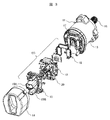
- FIG. 3 is an exploded perspective view of an electronic control unit of the electric power steering device shown in FIG.
- FIG. 4 is an explanatory diagram illustrating control blocks constituting the electronic control unit illustrated in FIG. 3.
- FIG. 5 is a perspective view showing a state before a control unit side power connector and a power unit side power connector are engaged. It is a perspective view which shows the state after the control part side power supply connector and the power supply part side power supply connector are engaged.
- FIG. 7 is a top view of the connector terminal assembly as viewed from the power supply side shown in FIG. 6.
- FIG. 3 is a perspective view of a power supply unit side power supply connector.
- FIG. 2 is a perspective view of an electric power steering device to which a connector terminal assembly is assembled.
- FIG. 10 is a perspective view showing a state in which a power supply side power connector is engaged with a connector terminal assembly of the electric power steering device shown in FIG. 9.
- the steering device 1 is configured as shown in FIG.
- a pinion 3 is provided at a lower end of a steering shaft 2 connected to a steering wheel (not shown), and the pinion 3 is engaged with a rack shaft which is long in the left-right direction of the vehicle body.
- Tie rods 5 for steering the front wheels in the left-right direction are connected to both ends of the rack shaft, and the rack shaft is covered by a rack housing 4.
- a rubber boot 6 is provided between the rack housing 4 and the tie rod 5.
- An electric power steering device 7 is provided to assist the torque when the steering wheel is turned. That is, a torque sensor 8 and a steering angle sensor 9 for detecting a turning direction and a turning torque of the steering shaft 2 are provided, and a steering assist is provided to a rack shaft via a reduction gear unit 10 based on a detection value of the torque sensor 8.
- An electric motor unit 11 for applying a force and an electronic control unit 12 arranged adjacent to the electric motor unit 11 for controlling the electric motor are provided.
- the electric motor unit 11 of the electric power steering device 7 is connected to the reduction gear unit 10 via three bolts (not shown) at the outer peripheral portion on the output shaft side, and is provided on the opposite side of the electric motor 11 unit from the output shaft.
- An electronic control unit 12 is provided.
- the torque sensor 8 detects the turning direction and the turning torque of the steering shaft 2.
- the control circuit of the electronic control unit 12 calculates the drive operation amount of the electric motor based on the detected value.
- the electric motor is driven by the power switching element of the power conversion circuit unit based on the calculated drive operation amount, and the output shaft of the electric motor is rotated so as to be driven in the same direction as the operation direction of the steering shaft 2.
- the rotation of the output shaft is transmitted from a pinion (not shown) to the rack shaft via the reduction gear unit 10, and the vehicle is steered. Since these configurations and operations are already well known, further description will be omitted.
- FIG. 2 shows the external appearance of the electric power steering device 7, which is different from the electric power steering device 7 in the configuration of the electronic control unit 12 of the electric power steering device 7 shown in FIG. Are the same.
- an electric motor unit 11 constituting the electric power steering device 7 includes a motor housing 13 having a cylindrical portion made of an aluminum alloy or the like and an electric motor (not shown) housed in the motor housing 13.
- Reference numeral 12 denotes a metal cover 14 made of an aluminum alloy or the like, which is arranged on the opposite side of the motor housing 13 from the output shaft in the axial direction, and an electronic control unit (not shown) housed in the metal cover.
- the motor housing 13 and the metal cover 14 are integrally fixed at their facing end surfaces with an adhesive, welding, or fixing bolts.
- the electronic control unit housed in the storage space inside the metal cover 14 includes a power supply circuit unit for generating a necessary power supply and a power switching element such as a MOSFET or IGBT for driving and controlling the electric motor of the electric motor unit 11. And a control circuit unit for controlling the power switching element.
- the output terminal of the power switching element and the coil input terminal of the electric motor are electrically connected via a bus bar.
- a connector terminal assembly 15 is fixed to the axial end surface of the motor housing 13 with fixing bolts, and a metal cover 14 is also fixed to the motor housing 13 so as to cover the connector terminal assembly 15.
- the connector terminal assembly 15 includes first and second control unit side power connectors 15A and 15B for supplying power, and a detection sensor connector 15C.
- the control unit-side power connector 15A and the second control unit-side power connector 15B are formed in different shapes, which is different from the embodiment of the present invention described later.
- the electronic control unit housed in the metal cover 14 receives electric power from the vehicle power supply unit (battery) via the first and second control unit side power supply connectors 15A and 15B for power supply made of synthetic resin. Also, detection signals such as an operation state are supplied from the detection sensors via the detection sensor connector 15C.
- FIG. 3 is an exploded perspective view of the electric power steering device 7.
- An annular iron side yoke (not shown) is fitted inside the motor housing 13, and an electric motor (not shown) is housed in the side yoke.
- the output unit 16 of the electric motor applies a steering assist force to the rack via a gear.
- the motor housing 13 is made of an aluminum alloy, and stores heat generated by the electric motor and heat generated by a power supply circuit unit and a power conversion circuit unit described later by the heat capacity of the motor housing 13 itself. It functions as a heat sink member to be released to the atmosphere.
- the electric motor unit 11 is configured by the electric motor and the motor housing 13.
- An electronic control unit ECU is mounted on the end wall 17 of the motor housing 13 opposite to the output unit 16 of the electric motor unit 11.
- the electronic control unit ECU includes a power conversion circuit unit 18, a power supply circuit unit 19, a control circuit unit 20, and a connector terminal assembly 15.
- the end wall portion 17 of the motor housing 13 is formed integrally with the motor housing 13, only the end wall portion 17 may be formed separately and integrated with the motor housing 13 by bolts or welding. Good thing.
- the power conversion circuit section 18, the power supply circuit section 19, and the control circuit section 20 constitute a redundant system, and constitute a dual system of the electronic control section A and the electronic control section B.
- the electric motor is normally controlled and driven by the electronic control unit A and the electronic control unit B. However, if an abnormality or failure occurs in one of the electronic control units, the electric motor is controlled by the other electronic control unit. It is driven. In other words, the electronic control unit A and the electronic control unit B are combined to function as a regular electronic control unit. If an abnormality or failure occurs in one of the electronic control units, the other electronic control unit controls the electric motor with half the capacity. Drive. In this case, the capacity of the electric motor is halved, but the "power steering function" is ensured.
- the dual electronic control unit ECU is composed of a power conversion circuit unit 18, a power supply circuit unit 19, a control circuit unit 20, and a connector terminal assembly 15, and the power is controlled in a direction away from the end wall 17 side.
- the conversion circuit section 18, the power supply circuit section 19, the control circuit section 20, and the connector terminal assembly 15 are arranged in this order.
- the control circuit unit 20 generates a control signal for driving the power switching element of the power conversion circuit unit 18, and includes a microcomputer, peripheral circuits, and the like.
- the power supply circuit section 19 generates a power supply voltage for driving the control circuit section 20 and a power supply voltage for the power conversion circuit section 18, and includes a capacitor, a coil, a switching element, and the like.
- the power conversion circuit section 18 adjusts the power flowing through the three-phase coils of the electric motor, and includes power switching elements and the like that form the three-phase upper and lower arms.
- a connector terminal assembly 15 made of a synthetic resin is provided between the control circuit unit 20 and the metal cover 14, and is connected to a vehicle power supply unit (battery) and detection sensors.
- the terminals embedded in the connector terminal assembly 15 are electrically connected to the power conversion circuit section 18, the power supply circuit section 19, and the control circuit section 20.
- the metal cover 14 has a function of accommodating the power conversion circuit section 18, the power supply circuit section 19, and the control circuit section 20 and sealing them in a watertight manner.
- the motor housing 13 is welded. Fixed to. Since the metal cover 14 is made of metal, it also has a function of radiating heat generated by the power conversion circuit section 18, the power supply circuit section 19, and the like to the outside.
- FIG. 4 shows a control block of the electronic control unit ECU provided in the electric power steering device 7.
- the electronic control unit ECU is configured as a redundant system, and includes a first electronic control unit (hereinafter, referred to as an electronic control unit A) 21 and a second electronic control unit (hereinafter, referred to as an electronic control unit B) 22.
- the electronic control unit A21 and the electronic control unit B22 individually drive and control each of the two divided electromagnetic coils A24 and B25 of the electric motor 23.
- the electronic control unit A21 is connected to the power supply terminal A26 and the ground terminal A27, and supplies power to the control circuit A29 via the power supply circuit unit 19 connected to the power supply terminal A26.
- the power terminal A26 and the ground terminal A27 are built in the first control unit side power connector 15A.
- the power supply terminal A26 and the ground terminal A27 are detachably connected to a power supply terminal A38 and a ground terminal A39 on the power supply side connected to the vehicle power supply unit (battery) via the first power supply harness.
- the power supply terminal A38 and the ground terminal A39 are built in the power supply unit side power supply connector.
- the control circuit A29 supplies a control signal to the switching element of the inverter circuit A30, and the inverter circuit A30 controls the supply of power to each phase of the electromagnetic coil A24 by the control signal. Further, a fail-safe relay circuit A31 is connected to the inverter circuit A30, and when an abnormality or failure occurs, the neutral point of the electromagnetic coil A24 is cut off to stop the operation of the electronic control unit A21.
- the electronic control unit B22 has the same configuration.
- the electronic control unit B22 is connected to the power supply terminal B32 and the ground terminal B33, and is connected to the control circuit B35 via the power supply circuit B34 connected to the power supply terminal B32. Power is being supplied.
- the power terminal B32 and the ground terminal B33 are built in the second control unit side power connector 15B.
- the power supply terminal B32 and the ground terminal B33 are detachably connected to a power supply side terminal B40 and a ground side terminal B41 connected to a vehicle power supply unit (battery) via a second power supply harness. Further, the power supply side terminal B40 and the ground side terminal B41 are built in the power supply section side power supply connector.
- the control circuit B35 supplies a control signal to the switching element of the inverter circuit B36, and the inverter circuit B36 controls the supply of power to each phase of the electromagnetic coil B25 according to the control signal. Further, a fail-safe relay circuit B37 is connected to the inverter circuit B36, and when an abnormality or failure occurs, the neutral point of the electromagnetic coil B25 is cut off to stop the operation of the electronic control unit B22.
- the power supply terminal A26 and the power supply terminal B32 use a common vehicle power supply (battery), and the supply voltage is the same.
- the ground terminal A27 and the ground terminal B33 are also commonly grounded.
- circuit components such as the power supply circuits 28 and 34, the control circuits 29 and 35, and the filter / fail-safe relay circuits 31 and 37 correspond to electric / electronic parts, and these electric / electronic parts are mounted on a substrate. And are electrically connected by wiring.
- both the electronic control unit A21 and the electronic control unit B22 are operating, and the share ratio of electric power sent to the electromagnetic coil A24 and the electromagnetic coil B25 of the electric motor 23 is 50%, respectively. %.
- the operation of the electronic control unit 21 or 22 in which the abnormality or the failure occurs is stopped, and the electric motor 23 is controlled by the remaining electronic control units 21 and 22. It is driven and controlled. As a result, the performance is reduced by half, but the "power steering function" is secured.
- the first and second control unit side power connectors 15A and 15B connected to the respective electronic control units A21 and B22,
- control section power connectors 15A and 15B and the power section power connector of each system are connected. It is easy to determine if the external shape is completely different, but it is preferable to form the external shape in the same shape considering the mass productivity of each power connector.
- control unit-side power connector and the power unit-side power connector of each system are formed in the same form, mechanical force of external force such as vibration acting on the control unit-side power connector and the power unit-side power connector and interference of an external device is generated. And the power supply connector on the control unit side of each system may fail at the same time.
- the present invention forms two control unit-side power connectors of the same configuration in an electronic control unit constituting a redundant system, and includes one control unit-side power connector and the other control unit-side power connector.
- the length in the axial direction is different, and the power supply unit side power connector common to the respective control unit power connectors is provided at the tip of the power harness having a length determined corresponding to the axial length.
- the power supply unit side power connector is engaged with each control unit side power connector according to the length of the power harness.
- the power supply unit side power connector is connected to the control unit side power connector according to the length of the power supply harness, so that erroneous assembly can be suppressed, and the axial length of each control unit side power connector can be reduced. Therefore, the influence environment based on external force and the like is also different, so that the possibility of failure at the same time can be reduced.
- FIGS. 5 to 7 show the first and second control unit-side power connectors 15A and 15B provided on the connector terminal assembly 15 and the first and second control unit-side power connectors 15A and 15B.
- 1 shows the first and second power supply side power connectors 42A and 42B engaged with the first and second power supply units.
- FIG. 5 shows a state before the first and second power supply connectors 15A and 15B are engaged with the first and second power supply connectors 42A and 42B
- FIG. 7 shows a state after the control unit side power supply connectors 15A, 15B and the first and second power supply unit side power supply connectors 42A, 42B are engaged.
- FIG. 7 shows FIG. 6 as the first and second power supply unit side power supplies. The state seen from the connectors 42A and 42B side is shown. The illustration of the first and second power supply harnesses and the control signal harnesses connected to the vehicle power supply unit (battery) is omitted.
- a power terminal A26 and a ground terminal A27 are built in the first control unit side power connector 15A (see FIG. 7), and a power terminal B32 and a ground terminal are provided in the second control unit power connector 15B.
- B33 is built in.
- each of the terminals A26, A27, B32B, and 33 may be incorporated by insert molding of a synthetic resin, or only each of the terminals A26, A27, B32B, and 33 may be insert-molded into a synthetic resin, and this may be made of a synthetic resin.
- the first and second control unit side power connectors 15A and 15B may be housed and housed.
- the first power supply unit side power connector 42A has a power supply terminal A38 and a ground terminal A39 built therein
- the second power supply unit side power supply connector 42B has a power supply terminal B40 and a ground terminal B41. Is built-in.
- first and second power supply harnesses connected to a vehicle power supply (battery) are connected to the first and second power supply side power connectors 42A and 42B. ing.
- the connector terminal assembly 15 has a flat area 43 formed therein, and fixing portions 44 are provided at four corners of the flat area 43.
- An insertion hole 45 through which a fixing bolt (not shown) is inserted is formed in the fixing portion 44, and the fixing terminal is screwed into the end wall 17 of the motor housing 13 by inserting the fixing bolt. It is fixed to the face wall 17.
- the first control unit side power connector 15A, the second control unit side power connector 15B, and the detection sensor connector 15C are provided in the plane region 43 of the connector terminal assembly 15 in a direction perpendicular to the plane region 43 (hereinafter, referred to as a vertical direction). , Defined as the axial direction of the connector). Further, the first control unit-side power connector 15A, the second control unit-side power connector 15B, and the detection sensor connector 15C are linearly arranged along the longitudinal direction of the planar region 43.
- the first control unit-side power connector 15A and the second control unit-side power connector 15B have the same cross section orthogonal to the axial direction, are formed in a substantially square shape, and have a cylindrical portion 46A made of synthetic resin. 46B.
- the cylindrical portion 46A of the first control unit side power connector 15A is composed of four orthogonal flat walls 47A-1 to 47A-4.
- the power supply terminal A26 and the ground terminal A27 shown in FIG. 4 are housed inside the cylindrical portion 46A. Further, a motor control terminal 48A is housed.
- tubular portion 46B of the second control unit side power connector 15B is composed of four orthogonal plane walls 47B-1 to 47B-4.
- the power supply terminal B32 and the ground terminal B33 shown in FIG. 4 are housed inside the cylindrical portion 46B. Further, a motor control terminal 48B is housed.
- the power terminal A26 and the ground terminal A27 housed in the cylindrical portion 46A of the first control unit side power connector 15A are located outside the plane region 43 at right angles to the longitudinal direction.
- the motor control terminal 48A is arranged along the plane wall 47A-1, and the motor control terminal 48A is arranged along the plane wall 47A-3 on the opposite side of the plane wall 47A-1.
- the power supply terminal B32 and the grounding terminal B33 housed in the cylindrical portion 46B of the second control unit side power supply connector 15B are arranged along the outer flat wall 47B-1 along the longitudinal direction of the flat area 43.
- the motor control terminal 48B is arranged along the plane wall 47B-3 on the opposite side of the plane wall 47B-2.
- a locking claw portion 49B is formed on the outer flat wall 47B-1 along the longitudinal direction of the flat region portion 43, which forms the cylindrical portion 46B of the second control unit side power connector 15B.
- the locking claw portion 49B is engaged with a locking portion 50B formed of a locking hole formed in the second power supply unit side power connector 42B to prevent the second power supply unit side power connector 42B from coming off. I'm trying.
- a locking claw portion 49A (not shown) is formed on an outer flat wall 47A-1 orthogonal to the longitudinal direction of the flat region portion 43, which forms the cylindrical portion 46A of the first control unit side power connector 15A.
- the locking claw portion 49A is engaged with a locking portion 50A (see FIG. 7) formed by a locking hole formed in the first power supply portion side power connector 42A, and is connected to the first power supply portion side.
- the power connector 42A is prevented from coming off.
- the outer flat wall 47A-1 orthogonal to the longitudinal direction of the planar region 43 of the tubular portion 46A and the outer planar wall 47B-1 along the longitudinal direction of the planar region 43 of the tubular portion 46B.
- the locking portion 50A of the first power supply portion side power connector 42A and the locking portion 50B of the second power supply portion side power connector 42B become The configuration may be such that it is not located on the facing surface between the tubular portion 46A and the tubular portion 46B and the facing surface between the tubular portion 46B and the detection sensor connector 15C. Thereby, the longitudinal lengths of the first control unit side power connector 15A, the second control unit side power connector 15B, and the detection sensor connector 15C can be reduced.
- the height (HA) of the cylindrical portion 46A of the first control unit side power connector 15A and the height (HB) of the cylindrical portion 46B of the second control unit side power connector 15B are:
- the height (length) is set to be different when viewed in the respective axial directions.
- the first control unit-side power connector 15A, the second control unit-side power connector 15B, and the detection sensor connector 15C which are linearly arranged along the longitudinal direction of the planar region 43
- the axial height (HA) of the cylindrical portion 46A of the arranged first control unit side power connector 15A is higher than the axial height of the cylindrical portion 46B of the second control unit side power connector 15B arranged at the center. (HB).
- the cylindrical portion 46A of the first control unit side power connector 15A disposed outside is increased.
- the second power supply section side power supply connector 42B engaged with 46B can be avoided from mechanical interference caused by other external devices or flying objects.
- the second control unit 15A may be damaged even if the first control unit side power connector 15A is damaged.
- the unit-side power connector 15B can be prevented from being damaged.
- both the first control section power connector 15A and the second control section power connector 15B are provided. May be damaged. Thus, it is possible to reduce the failure of the second control unit side power supply connector 15B.
- FIG. 8 shows a first power supply unit side power supply connector 42A and a second power supply unit side power supply connector 42B, which are formed in the same shape. Therefore, the following description will be made as a common power supply side power supply connector.
- the power-supply-side power connector 42A (42B) is a cross section orthogonal to the axial direction that covers the cylindrical portion 46A of the first control-portion power connector 15A and the cylindrical portion 46B of the second control-portion power connector 15B from outside. Are provided with a rectangular tubular portion 51A (51B). Therefore, the cylindrical portion 51A (51B) of the power supply unit side power connector 42A (42B) is connected to the cylindrical portion 46A of the first control unit power supply connector 15A and the cylindrical portion 46B of the second control unit power supply connector 15B. And the power supply unit side power connector 42A (42B) can be engaged with the first and second control unit side power connectors 15A and 15B.
- the first and second cylindrical portions 51A (51B) are provided on the opposite sides of the cylindrical portion 46A of the first control unit side power connector 15A and the cylindrical portion 46B of the second control unit side power connector 15B.
- a power harness connecting portion 52A (52B) to which two power harnesses are connected and a control harness connecting portion 53A (53B) to which a motor control harness is connected are provided. Note that the control harness connection portion 53A (53B) to which the motor control harness is connected may be omitted as necessary.
- the cylindrical portion 51A (51B) is composed of four flat walls 54A-1 to 54A-4 (52B-1 to 52B-4), and is connected to a power harness.
- a locking portion 50A (50B) that engages with the locking claws 49A, 49B (see FIG. 5) is formed on the flat wall 54A-1 (54B-1) where the portion 52A (52B) is formed.
- FIG. 9 shows a state in which the connector terminal assembly 15 having the above-described configuration is incorporated in the electric power steering device 7.
- an electronic control unit ECU (see FIG. 3) is assembled to the motor housing 13 and hermetically sealed by a metal cover 14 from the outside.
- An opening 14S is formed in a top portion 14T of the metal cover 14, and a first control unit side power connector 15A, a second control unit side power connector 15B, and a detection sensor formed in the connector terminal assembly 15 from the opening 14S.
- Connector 15C is projected and exposed along the axis of the rotating shaft of the electric motor.
- the axial height (HA) of the first control unit power connector 15A is higher than the axial height (HB) of the second control unit power connector 15B as described above.
- the first and second power supply side power connectors 42A and 42B are engaged with the connector terminal assembly 15 in this state, and the first control unit side power connector 15A and the power supply side The power supply connector 42A is electrically connected, and the second control unit side power supply connector 15B and the second power supply unit side power supply connector 42B are electrically connected.
- the first and second power harnesses are different.
- the length is determined accordingly. Therefore, the first power supply unit side power connector 42A provided at the end of the first power supply harness is incorrectly assembled to the second control unit side power connector 15B, and the second power supply unit side power supply provided at the end of the second power supply harness.
- the connector 42B is erroneously assembled to the first control unit side power supply connector 15A, since the lengths of the first and second power supply harnesses do not match, the erroneous assembly can be easily determined, and further reassembly. Can be easily performed.
- first control unit-side power connector 15A and the second control unit-side power connector 15B have different axial heights, when the first and second power unit-side power connectors 42A and 42B are engaged, The arrangement environment of the first control section power connector 15A and the first power section power connector 42A is different from the arrangement environment of the second control section power connector 15B and the second power section power connector 42B. Therefore, it is possible to reduce the probability that these power supply connectors simultaneously cause an abnormality or a failure. For example, even if an abnormality occurs in one of the vibration modes, the other is not affected by the vibration mode.
- the arrangement environment of the first control unit side power connector 15A and the first power unit side power connector 42A is reduced. Since the arrangement environment of the second control unit side power supply connector 15B and the second power supply unit side power supply connector 42B is in the same state, there is a possibility that a certain vibration mode may cause an abnormality in both.
- the second control unit may be damaged even if the first control unit side power connector 15A is damaged.
- the side power supply connector 15B can avoid damage.
- the axial height (HB) of the cylindrical portion 46B of the second control unit side power connector 15B is increased, both the first control unit side power connector 15A and the second control unit side power connector 15B are damaged. May be done. Thus, it is possible to suppress the second control unit side power supply connector 15B from breaking down.
- first and second power supply side power connectors 42A and 42B can be used in common by the first control unit power supply connector 15A and the second control unit power supply connector 15B, the power supply unit side power supply connector is mass-produced. It is advantageous in doing so.
- control unit side power connector is rephrased as “control unit side connector”
- power unit side power connector is rephrased as “non-control unit side connector”
- power harness is simply rephrased as “harness”.
- the present invention has the following features, and the following actions and effects can be obtained by these features.
- the electronic control unit includes a first electronic control unit and a second electronic control unit that constitute a redundant system, and the first electronic control unit and the second electronic control unit have the same first control unit.
- a first connector and a second controller are provided at different heights in the axial direction in which the respective connectors extend.
- a first control unit side connector and a second control unit side connector are provided at the distal ends of a first harness and a second harness having a length corresponding to the axial height of the first control unit side connector and the second control unit side connector.
- a first non-control unit-side connector and a second non-control unit-side connector common to the control unit-side connector are provided, and the first control unit-side connector and the second control unit are adjusted to match the lengths of the first harness and the second harness.
- the first non-control unit side connector and the second non-control unit side connector It was a combined configuration.
- the electronic control unit includes a first electronic control unit and a second electronic control unit that constitute a redundant system and are connected to the vehicle power supply unit. Is provided with a first control unit-side power connector and a second control unit-side power connector having the same configuration, and the first control unit-side power connector and the second control unit-side power connector are arranged in a direction in which the respective power connectors extend.
- a first power supply harness having different heights in the direction and having a length determined in accordance with the axial height of the first control section power connector and the second control section power connector.
- a first power supply unit side connector and a second power supply unit side connector common to the first control unit side power supply connector and the second control unit side power supply connector at the end of the second power supply harness.
- First control unit side according to the length of the second power harness Source connector and the first power source unit side connector and the second power source unit side connector is configured to engaged with the second controller side power connector.
- the non-control unit-side connector (power supply unit-side power connector) is connected to the control unit-side connector (control unit-side power supply connector) according to the length of the harness (power supply harness). Assembling can be suppressed, and since the axial lengths of the respective control unit side connectors are different, mechanical effects based on external force and the like are different, so that it is possible to reduce the risk of failure at the same time.
- the present invention is not limited to the above-described embodiment, but includes various modifications.
- the above-described embodiments have been described in detail in order to explain the present invention in an easy-to-understand manner, and are not necessarily limited to those having all the described configurations.
- a part of the configuration of one embodiment can be replaced with the configuration of another embodiment, and the configuration of one embodiment can be added to the configuration of another embodiment.
Landscapes
- Engineering & Computer Science (AREA)
- Chemical & Material Sciences (AREA)
- Combustion & Propulsion (AREA)
- Transportation (AREA)
- Mechanical Engineering (AREA)
- Power Engineering (AREA)
- Microelectronics & Electronic Packaging (AREA)
- Power Steering Mechanism (AREA)
- Motor Or Generator Frames (AREA)
Abstract
冗長系を構成する電子制御部ECUに同じ構成の2つの制御部側電源コネクタ15A、15Bを形成し、一方の制御部側電源コネクタ15Aと他方の制御部側電源コネクタ15Bの軸方向の長さを異なる長さとし、この軸方向の長さに対応して決められた長さを有する電源ハーネスの先端に、夫々の制御部側電源コネクタ15A、15Bに共通な電源部側電源コネクタ42A、42Bを設け、電源ハーネスの長さに合せて夫々の制御部側電源コネクタ15A、15Bに電源部側電源コネクタ42A、42Bを係合した。 上記構成によって、夫々の系統の電源コネクタの誤組み付けを抑制し、且つ夫々の系統の電源コネクタが同時に故障を発生するのを抑制することができる。
Description
本発明は、電動駆動装置及び電動パワーステアリング装置に係り、特に電子制御部を内蔵した電動駆動装置及び電動パワーステアリング装置に関するものである。
一般的な産業機械分野においては、電動モータによって機械系制御要素を駆動することが行われているが、最近では電動モータの回転速度や回転トルクを制御する半導体素子等からなる電子制御部を電動モータに一体的に組み込む、いわゆる機電一体型の電動駆動装置が採用され始めている。
機電一体型の電動駆動装置の例として、例えば自動車の電動パワーステアリング装置においては、運転者がステアリングホィールを操作することにより回動するステアリングシャフトの回動方向と回動トルクとを検出し、この検出値に基づいてステアリングシャフトの回動方向と同じ方向へ回動するように電動モータを駆動し、操舵アシストトルクを発生させるように構成されている。この電動モータを制御するため、電子制御部(ECU:Electronic Control Unit)がパワーステアリング装置に設けられている。
従来の電動パワーステアリング装置としては、例えば、特開2016-144380号公報(特許文献1)に記載のものが知られている。この特許文献1には、電動モータ部と電子制御部とにより構成された電動パワーステアリング装置が記載されている。そして、電動モータ部の電動モータは、アルミ合金等から作られた筒部を有するモータハウジングに形成された収納空間に収納され、電子制御部の電子部品が実装された回路基板は、モータハウジングの軸方向の出力軸とは反対側の端面壁部に、合成樹脂製、或いは金属製のカバーによって形成された収納空間に収納されている。
モータハウジングの端面壁部に取り付けられる電子制御部の回路基板は、電動モータを駆動制御するMOSFET、或いはIGBT等のようなパワースイッチング素子を有する電力変換回路部、電源電圧を生成する電源回路部及びパワースイッチング素子を制御する制御回路部を備え、パワースイッチング素子の出力端子と電動モータの入力端子とはバスバーを介して電気的に接続されている。
また、最近では電動モータの巻線を二重系とし、この二重系の巻線を夫々同じ構成の電子制御部で制御する冗長系(二重系)システムが提案されている。例えば、特開2016-554994号公報(特許文献2)に示された冗長系(二重系)システムは、第1電子制御部と第2電子制御部を合せて正規の電子制御部として機能させ、一方の電子制御部に異常、故障が生じると、他方の電子制御部で半分の能力によって電動モータを制御、駆動する構成としている。この場合、電動モータの能力は半分となるが、いわゆる「パワーステアリング機能」は確保されるようになっている。尚、特許文献2においては、冗長系であるので電源コネクタ等のコネクタ類は、夫々の電子制御部に個別に備え付けられている。
尚、この他に電子制御部を一体化した電動駆動装置としては、電動ブレーキや各種油圧制御用の電動油圧制御器等が知られているが、以下の説明では代表して電動パワーステアリング装置について説明する。
ところで、このような冗長系に構成された電子制御部においては、夫々の系統を個別に制御することが要請されてきている。そして、このような要請に合せて、夫々の電子制御部を「マスター系」と「スレーブ系」とに切り分けることが考えられている。
このため、夫々の電子制御部に接続される電源コネクタ(以下、制御部側電源コネクタと表記する)と、この第1、第2制御部側電源コネクタに着脱自在に係合され、電源ハーネスを介して車両電源部(バッテリ)に接続されている電源コネクタ(以下、電源部側電源コネクタと表記する)の間にも組み合せの整合性が要求され、制御部側電源コネクタと電源部側電源コネクタの誤組み付けを回避することが必要とされている。
制御部側電源コネクタと電源部側電源コネクタの誤組み付けを回避するためには、夫々の系統の制御部側電源コネクタと電源部側電源コネクタの外観形状を全く異なった形状にすれば判別は容易であるが、電源コネクタの量産性等を考慮すると外観形状を同じ形状にすることが好ましい。
しかしながら、夫々の系統の制御部側電源コネクタと電源部側電源コネクタを同じ形態に形成すると、制御部側電源コネクタと電源部側電源コネクタに作用する振動や外部機器の干渉等の外力に基づく機械的影響が同じ状態になり、結果的に夫々の系統の制御部側電源コネクタと電源部側電源コネクタが同時に故障を生じるといった現象が発現する。
このように、夫々の系統の制御部側電源コネクタと電源部側電源コネクタが同時に故障を生じると、冗長系に構成したパワーステアリング機能が喪失されることになる。したがって、夫々の系統の制御部側電源コネクタと電源部側電源コネクタの誤組み付けを抑制し、且つ夫々の系統の制御部側電源コネクタと電源部側電源コネクタが同時に故障を発生するのを抑制することが必要である。
本発明の目的の一つは、夫々の系統の電源コネクタの誤組み付けを抑制し、且つ夫々の系統の電源コネクタが同時に故障を発生するのを抑制することができる電動駆動装置及び電動パワーステアリング装置を提供することにある。
本発明の一つの態様としては、電子制御部が、冗長系を構成する第1電子制御部と第2電子制御部からなり、第1電子制御部と第2の電子制御部には、同じ構成の第1制御部側コネクタと第2制御部側コネクタが設けられ、第1制御部側コネクタと第2制御部側コネクタは、夫々のコネクタが延びる方向の軸方向高さが、異なる高さに形成されていると共に、第1制御部側コネクタと第2制御部側コネクタの軸方向高さに対応して決められた長さを有する第1ハーネスと第2ハーネスの先端に、第1制御部側コネクタと第2制御部側コネクタに共通な第1非制御部側コネクタと第2非制御部側コネクタとを設け、第1ハーネスと第2ハーネスの長さに合せて第1制御部側コネクタと第2制御部側コネクタに第1非制御部側コネクタと第2非制御部側コネクタを係合した、ところにある。
本発明の更なる態様は、電子制御部が、車両電源部に接続された、冗長系を構成する第1電子制御部と第2電子制御部からなり、第1電子制御部と第の電子制御部には、同じ構成の第1制御部側電源コネクタと第2制御部側電源コネクタが設けられ、第1制御部側電源コネクタと第2制御部側電源コネクタは、夫々の電源コネクタが延びる方向の軸方向高さが、異なる高さに形成されていると共に、第1制御部側電源コネクタと第2制御部側電源コネクタの軸方向高さに対応して決められた長さを有する第1電源ハーネスと第2電源ハーネスの先端に、第1制御部側電源コネクタと第2制御部側電源コネクタに共通な第1電源部部側コネクタと第2電源部側コネクタとを設け、第1電源ハーネスと第2電源ハーネスの長さに合せて、第1制御部側電源コネクタと第2制御部側電源コネクタに第1電源部側コネクタと第2電源部側コネクタを係合した、ところにある。
本発明の態様によれば、ハーネス(電源ハーネス)の長さに合せて、非制御部側コネクタ(電源部側電源コネクタ)を制御部側コネクタ(制御部側電源コネクタ)に連結するので、誤組み付を抑制でき、且つ、夫々の制御部側コネクタの軸方向の長さが異なるので、外力等に基づく機械的影響も異なるため同時に故障する恐れを少なくすることが可能となる。
以下、本発明の実施形態について図面を用いて詳細に説明するが、本発明は以下の実施形態に限定されることなく、本発明の技術的な概念の中で種々の変形例や応用例をもその範囲に含むものである
本発明の実施形態を説明する前に本発明が適用される一例としての操舵装置の構成及び電動パワーステアリング装置の構成について、図1~図4を用いて簡単に説明する。
本発明の実施形態を説明する前に本発明が適用される一例としての操舵装置の構成及び電動パワーステアリング装置の構成について、図1~図4を用いて簡単に説明する。
まず、自動車の前輪を操舵するための操舵装置について説明する。操舵装置1は図1に示すように構成されている。図示しないステアリングホイールに連結されたステアリングシャフト2の下端にはピニオン3が設けられ、このピニオン3は車体左右方向へ長いラック軸と噛み合っている。このラック軸の両端には前輪を左右方向へ操舵するためのタイロッド5が連結されており、ラック軸はラックハウジング4に覆われている。そして、ラックハウジング4とタイロッド5との間にはゴムブーツ6が設けられている。
ステアリングホイールを回動操作する際のトルクを補助するため、電動パワーステアリング装置7が設けられている。即ち、ステアリングシャフト2の回動方向と回動トルクとを検出するトルクセンサ8、舵角センサ9が設けられ、トルクセンサ8の検出値に基づいてラック軸に減速ギヤ部10を介して操舵補助力を付与する電動モータ部11と、電動モータ部11に隣接して配置された、電動モータを制御する電子制御ユニット12とが設けられている。
また、電動パワーステアリング装置7の電動モータ部11は、出力軸側の外周部の3箇所が図示しないボルトを介して減速ギヤ部10に接続され、電動モータ11部の出力軸とは反対側に電子制御ユニット12が設けられている。
電動パワーステアリング装置7においては、ステアリングホイールが操作されることによりステアリングシャフト2がいずれかの方向へ回動操作されると、このステアリングシャフト2の回動方向と回動トルクとをトルクセンサ8が検出し、この検出値に基づいて電子制御ユニット12の制御回路部が電動モータの駆動操作量を演算する。
この演算された駆動操作量に基づいて電力変換回路部のパワースイッチング素子により電動モータが駆動され、電動モータの出力軸はステアリングシャフト2の操作方向と同じ方向へ駆動するように回動される。出力軸の回動は、図示しないピニオンから減速ギヤ部10を介してラック軸へ伝達され、自動車が操舵される。これらの構成、作用は既によく知られているので、これ以上の説明は省略する。
図2は電動パワーステアリング装置7の外観を示しているが、この電動パワーステアリング装置7は、図1に示す電動パワーステアリング装置7の電子制御ユニット12の構成が異なったものであるが、機能としては同じものである。
図2において、電動パワーステアリング装置7を構成する電動モータ部11は、アルミ合金等から作られた筒部を有するモータハウジング13及びこれに収納された図示しない電動モータとから構成され、電子制御ユニット12は、モータハウジング13の軸方向の出力軸とは反対側に配置された、アルミ合金等で作られた金属カバー14、及びこれに収納された図示しない電子制御部から構成されている。
モータハウジング13と金属カバー14は、その対向端面で、接着剤、或いは溶着、或いは固定ボルトによって一体的に固定されている。金属カバー14の内部の収納空間に収納された電子制御部は、必要な電源を生成する電源回路部や、電動モータ部11の電動モータを駆動、制御するMOSFET或いはIGBT等からなるパワースイッチング素子を有する電力変換回路や、このパワースイッチング素子を制御する制御回路部からなり、パワースイッチング素子の出力端子と電動モータのコイル入力端子とはバスバーを介して電気的に接続されている。
モータハウジング13の軸方向の端面には、コネクタ端子組立体15が固定ボルトによって固定されており、これを覆うように金属カバー14もモータハウジング13に固定されている。コネクタ端子組立体15には、電力供給用の第1、第2制御部側電源コネクタ15A、15B、検出センサ用コネクタ15Cを備えている。尚、図2においては、制御部側電源コネクタ15Aと第2制御部側電源コネクタ15Bとは、異なった形状に形成されており、この点で後述する本発明の実施形態と異なっている。
そして、金属カバー14内に収納された電子制御部は、合成樹脂から作られた電力供給用の第1、第2制御部側電源コネクタ15A、15Bを介して車両電源部(バッテリ)から電力が供給され、また検出センサ類から運転状態等の検出信号が検出センサ用コネクタ15Cを介して供給されている。
図3に電動パワーステアリング装置7の分解斜視図を示している。モータハウジング13の内部には、円環状の鉄製のサイドヨーク(図示せず)が嵌合されており、このサイドヨーク内に電動モータ(図示せず)が収納されている。電動モータの出力部16はギヤを介してラックに操舵補助力を付与している。
モータハウジング13は、アルミ合金から作られており、電動モータで発生した熱や、後述する電源回路部や電力変換回路部で発生した熱を、モータハウジング13自体の熱容量により蓄熱し、その後に外部大気に放出するヒートシンク部材として機能している。電動モータとモータハウジング13によって電動モータ部11を構成している。
電動モータ部11の出力部16の反対側のモータハウジング13の端面壁部17には、電子制御部ECUが取り付けられている。電子制御部ECUは、電力変換回路部18、電源回路部19、制御回路部20、コネクタ端子組立体15から構成されている。モータハウジング13の端面壁部17は、モータハウジング13と一体的に形成されているが、この他に端面壁部17だけを別体に形成し、ボルトや溶接によってモータハウジング13と一体化しても良いものである。
ここで、電力変換回路部18、電源回路部19、制御回路部20は、冗長系を構成するものであり、電子制御部Aと電子制御部Bの二重系を構成している。そして、通常は電子制御部A、及び電子制御部Bによって電動モータが制御、駆動されているが、一方の電子制御部に異常や故障が生じると、他方の電子制御部によって電動モータが制御、駆動されるものである。つまり、電子制御部Aと電子制御部Bを合せて正規の電子制御部として機能させ、一方の電子制御部に異常、故障が生じると、他方の電子制御部で半分の能力によって電動モータを制御、駆動するものである。この場合、電動モータの能力は半分となるが、「パワーステアリング機能」は確保されるようになっている。
二重系の電子制御部ECUは、電力変換回路部18、電源回路部19、制御回路部20、コネクタ端子組立体15から構成されており、端面壁部17側から離れる方向に向かって、電力変換回路部18、電源回路部19、制御回路部20、コネクタ端子組立体15の順序で配置されている。
制御回路部20は電力変換回路部18のパワースイッチング素子を駆動する制御信号を生成するもので、マイクロコンピュータ、周辺回路等から構成されている。電源回路部19は、制御回路部20を駆動する電源電圧、及び電力変換回路部18の電源電圧を生成するもので、コンデンサ、コイル、スイッチング素子等から構成されている。電力変換回路部18は、電動モータの三相のコイルに流れる電力を調整するもので、三相の上下アームを構成するパワースイッチング素子等から構成されている。
制御回路部20と金属カバー14の間には、合成樹脂からなるコネクタ端子組立体15が設けられており、車両電源部(バッテリ)や検出センサ類と接続されている。もちろん、このコネクタ端子組立体15に埋設された端子類は、電力変換回路部18、電源回路部19、制御回路部20と電気的に接続されている。
金属カバー14は、電力変換回路部18、電源回路部19、制御回路部20を収納してこれらを水密的に封止する機能を備えているものであり、本実施形態では溶着によってモータハウジング13に固定されている。この金属カバー14は、金属で作られているので、電力変換回路部18、電源回路部19等によって発生した熱を外部に放熱する機能も併せ備えている。
図4は、電動パワーステアリング装置7に設けられている電子制御部ECUの制御ブロックを示している。電子制御部ECUは、冗長系として構成されており、第1電子制御部(以下、電子制御部Aと表記する)21と第2電子制御部(以下、電子制御部Bと表記する)22とから構成され、それぞれの電子制御部A21、電子制御部B22は、電動モータ23の2分割された夫々の電磁コイルA24、電磁コイルB25を個別に駆動、制御するものである。
電子制御部A21は、電源端子A26と接地端子A27に接続されており、電源端子A26に接続された電源回路部19を介して制御回路A29に電力を供給している。この電源端子A26と接地端子A27は、第1制御部側電源コネクタ15Aに内蔵されている。
電源端子A26と接地端子A27は、車両電源部(バッテリ)に第1電源ハーネスで接続された電源側の電源端子A38と接地端子A39と着脱自在に接続される。また、電源端子A38と接地端子A39は、電源部側電源コネクタに内蔵されている。
電源端子A26と接地端子A27は、車両電源部(バッテリ)に第1電源ハーネスで接続された電源側の電源端子A38と接地端子A39と着脱自在に接続される。また、電源端子A38と接地端子A39は、電源部側電源コネクタに内蔵されている。
制御回路A29は、インバータ回路A30のスイッチング素子に制御信号を供給し、この制御信号によってインバータ回路A30は、電磁コイルA24の各相への電力の供給を制御している。また、インバータ回路A30には、フェールセーフリレー回路A31が接続されており、異常や故障が生じると電磁コイルA24の中性点を遮断して電子制御部A21の動作を停止する。
一方、電子制御部B22も同じ構成とされており、電子制御部B22は、電源端子B32と接地端子B33に接続されており、電源端子B32に接続された電源回路B34を介して制御回路B35に電力を供給している。この電源端子B32と接地端子B33は、第2制御部側電源コネクタ15Bに内蔵されている。また、電源端子B32と接地端子B33は、車両電源部(バッテリ)に第2電源ハーネスで接続された電源側の電源側端子B40と接地側端子B41と着脱自在に接続される。また、電源側端子B40と接地側端子B41は、電源部側電源コネクタに内蔵されている。
制御回路B35は、インバータ回路B36のスイッチング素子に制御信号を供給し、この制御信号によってインバータ回路B36は、電磁コイルB25の各相への電力の供給を制御している。また、インバータ回路B36には、フェールセーフリレー回路B37が接続されており、異常や故障が生じると電磁コイルB25の中性点を遮断して電子制御部B22の動作を停止する。
尚、電源端子A26と電源端子B32は共通の車両電源部(バッテリ)を使用しており、供給電圧は同一である。また、接地端子A27と接地端子B33も共通に接地されている。更に、電源回路28、34、制御回路29、35、フィルタ/フェールセーフリレー回路31、37等の回路構成部品は、電気/電子部品に該当するものであり、これらの電気/電子部品は基板上に配置され、配線によって電気的に接続されている。
正常な状態での電子制御部ECUの動作は、電子制御部A21と電子制御部B22の両方が動作しており、電動モータ23の電磁コイルA24と電磁コイルB25に送る電力の分担率はそれぞれ50%である。そして、一方の電子制御部21、22に異常や故障が生じると、異常や故障が生じた電子制御部21、22はその動作を停止され、残りの電子制御部21、22によって電動モータ23が駆動、制御されるものである。これによって、能力は半分に低下するが、「パワーステアリング機能」は確保されるものとなる。
このような二重系を備えた電子制御装部においては、上述した通り、夫々の電子制御部A21、電子制御部B22に接続される第1、第2制御部側電源コネクタ15A、15Bと、この制御部側電源コネクタ15A、15Bに着脱自在に係合され、第1、第2電源ハーネスを介して車両電源部(バッテリ)に接続されている電源部側電源コネクタの間にも組み合せの整合性が要求され、第1、第2制御部側電源コネクタ15A、15Bと電源部側電源コネクタの誤組み付けを回避することが必要とされている。
制御部側電源コネクタと電源部側電源コネクタの誤組み付けを回避するためには、図2、図3にあるように、夫々の系統の制御部側電源コネクタ15A、15Bと電源部側電源コネクタの外観形状を全く異なった形状に形成すれば判別は容易であるが、夫々の電源コネクタの量産性等を考慮すると外観形状を同じ形状に形成することが好ましい。
しかしながら、夫々の系統の制御部側電源コネクタと電源部側電源コネクタを同じ形態に形成すると、制御部側電源コネクタと電源部側電源コネクタに作用する振動や外部機器の干渉等の外力の機械的な影響が同じ状態になり、結果的に夫々の系統の制御部側電源コネクタと電源部側電源コネクタが同時に故障を生じるといった現象が発現する。
本発明はこのような課題に対応すべく、冗長系を構成する電子制御部に同じ構成の2つの制御部側電源コネクタを形成し、一方の制御部側電源コネクタと他方の制御部側電源コネクタの軸方向の長さを異なる長さとし、この軸方向の長さに対応して決められた長さを有する電源ハーネスの先端に、夫々の制御部側電源コネクタに共通な電源部側電源コネクタを設け、電源ハーネスの長さに合せて夫々の制御部側電源コネクタに電源部側電源コネクタを係合した構成としたものである。
これによれば、電源ハーネスの長さに合せて、電源部側電源コネクタを制御部側電源コネクタに連結するので誤組み付けを抑制でき、且つ、夫々の制御部側電源コネクタの軸方向の長さが異なるので、外力等に基づく影響環境も異なるため同時に故障する恐れを少なくすることが可能となる。
以下、本発明の実施形態を図面に基づき詳細に説明する。先ず、図5~図7は、コネクタ端子組立体15に設けられた第1、第2制御部側電源コネクタ15A、15Bと、この第1、第2制御部側電源コネクタ15A、15Bに着脱可能に係合される第1、第2電源部側電源コネクタ42A、42Bを示している。
図5は、第1、第2制御部側電源コネクタ15A、15Bと第1、第2電源部側電源コネクタ42A、42Bが係合される前の状態を示し、図6は、第1、第2制御部側電源コネクタ15A、15Bと第1、第2電源部側電源コネクタ42A、42Bが係合された後の状態を示し、図7は、図6を第1、第2電源部側電源コネクタ42A、42B側から見た状態を示している。尚、車両電源部(バッテリ)に繋がる第1、第2電源ハーネスや制御信号用ハーネスについては図示を省略している。
第1制御部側電源コネクタ15Aには、図4に示しように電源端子A26と接地端子A27が内蔵(図7参照)され、第2制御部側電源コネクタ15Bには、電源端子B32と接地端子B33が内蔵されている。例えば、夫々の端子A26、A27、B32B、33は合成樹脂のインサートモールドによって内蔵しても良いし、夫々の端子A26、A27、B32B、33だけを合成樹脂にインサートモールドし、これを合成樹脂で作られた第1、第2制御部側電源コネクタ15A、15Bに収納して内蔵しても良い。
また、第1電源部側電源コネクタ42Aには、図4に示しように電源端子A38と接地端子A39が内蔵され、第2電源部側電源コネクタ42Bには、電源側端子B40と接地側端子B41が内蔵されている。ここで、図面での表示は省略しているが、第1、第2電源部側電源コネクタ42A、42Bには、車両電源部(バッテリ)に接続された第1、第2電源ハーネスが接続されている。
コネクタ端子組立体15は、平面領域部43が形成されており、この平面領域部43の四隅に固定部44が設けられている。固定部44には固定ボルト(図示せず)が挿通する挿通孔45が形成され、固定ボルトを挿通してモータハウジング13の端面壁部17にねじ止めすることで、コネクタ端子組立体15は端面壁部17に固定される。
コネクタ端子組立体15の平面領域部43には、第1制御部側電源コネクタ15A、第2制御部側電源コネクタ15B、及び検出センサ用コネクタ15Cが、平面領域部43に対して垂直方向(以下、コネクタの軸線方向と定義する)に延びて植立されている。また、第1制御部側電源コネクタ15A、第2制御部側電源コネクタ15B、及び検出センサ用コネクタ15Cは、平面領域部43の長手方向にそって、直線状に配置されている。
そして、第1制御部側電源コネクタ15A、第2制御部側電源コネクタ15Bの軸線方向に直交した断面は同じ形状に形成されており、略正方形に形成され、合成樹脂からなる筒状部46A、46Bとされている。
図7に示しているように、第1制御部側電源コネクタ15Aの筒状部46Aは、直交する4個の平面壁47A-1~47A-4から構成されている。また、筒状部46Aの内部には、図4に示す電源端子A26、接地端子A27が収納されている。更にはモータ制御用端子48Aが収納されている。
同様に、第2制御部側電源コネクタ15Bの筒状部46Bは、直交する4個の平面壁47B-1~47B-4から構成されている。また、筒状部46Bの内部には、図4に示す電源端子B32、接地端子B33が収納されている。更にはモータ制御用端子48Bが収納されている。
そして、図7に示しているように、第1制御部側電源コネクタ15Aの筒状部46Aに収納されている電源端子A26、接地端子A27は、平面領域部43の長手方向に直交する外側の平面壁47A-1に沿って配置され、モータ制御用端子48Aは、平面壁47A-1の反対側の平面壁47A-3に沿って配置されている。
一方、第2制御部側電源コネクタ15Bの筒状部46Bに収納されている電源端子B32、接地端子B33は、平面領域部43の長手方向に沿った外側の平面壁47B-1に沿って配置され、モータ制御用端子48Bは、平面壁47B-2の反対側の平面壁47B-3に沿って配置されている。
図5に戻って、第2制御部側電源コネクタ15Bの筒状部46Bを形成する、平面領域部43の長手方向に沿った外側の平面壁47B-1には、係止爪部49Bが形成されており、この係止爪部49Bは、第2電源部側電源コネクタ42Bに形成した係止孔からなる係止部50Bに係合して、第2電源部側電源コネクタ42Bの抜け止めを図っている。
同様に、第1制御部側電源コネクタ15Aの筒状部46Aを形成する、平面領域部43の長手方向に直交する外側の平面壁47A-1には、係止爪部49A(図示せず)が形成されており、この係止爪部49Aは、第1電源部側電源コネクタ42Aに形成した係止孔からなる係止部50A(図7参照)に係合して、第1電源部側電源コネクタ42Aの抜け止めを図っている。
このように、筒状部46Aの平面領域部43の長手方向に直交する外側の平面壁47A-1と、筒状部46Bの平面領域部43の長手方向に沿った外側の平面壁47B-1に係止爪部49A、49Bを設けると、図7に示しているように、第1電源部側電源コネクタ42Aの係止部50Aと第2電源部側電源コネクタ42Bの係止部50Bが、筒状部46Aと筒状部46Bの対向面、及び筒状部46Bと検出センサ用コネクタ15Cの対向面に位置しない構成とすることができる。これによって、第1制御部側電源コネクタ15A、第2制御部側電源コネクタ15B、及び検出センサ用コネクタ15Cの長手方向の長さを短くできる。
図5に示されている通り、第1制御部側電源コネクタ15Aの筒状部46Aの高さ(HA)、及び第2制御部側電源コネクタ15Bの筒状部46Bの高さ(HB)は、夫々の軸線方向で見て、その高さ(長さ)が異なるように設定されている。本実施形態では、平面領域部43の長手方向に沿って直線状に配置された、第1制御部側電源コネクタ15A、第2制御部側電源コネクタ15B、及び検出センサ用コネクタ15Cにおいて、外側に配置された第1制御部側電源コネクタ15Aの筒状部46Aの軸方向高さ(HA)の方が、中央に配置された第2制御部側電源コネクタ15Bの筒状部46Bの軸方向高さ(HB)より高く設定されている。
このように、外側に配置された第1制御部側電源コネクタ15Aの筒状部46Aの軸方向高さ(HA)を高くすることによって、隣接する第2制御部側電源コネクタ15Bの筒状部46Bに係合される第2電源部側電源コネクタ42Bを、他の外部機器や飛来物に起因する機械的な干渉から避けることができる。
例えば、他の外部機器や飛来物が、第1制御部側電源コネクタ15Aの筒状部46Aの側から到来した場合、第1制御部側電源コネクタ15Aの方は破損しても、第2制御部側電源コネクタ15Bの方は破損を免れることが可能となる。逆に、第2制御部側電源コネクタ15Bの筒状部46Bの軸法h校高さ(HB)を高くすると、第1制御部側電源コネクタ15A、及び第2制御部側電源コネクタ15Bの両方が破損される恐れがある。このように、第2制御部側電源コネクタ15Bの故障を低減することが可能となる。
次に、第1、第2電源部側電源コネクタ42A、42Bの構成について説明する。図8は第1電源部側電源コネクタ42Aと第2電源部側電源コネクタ42Bを示しており、これらは同じ形状に形成されている。したがって、以下では共通の電源側電源コネクタとして説明する。
電源部側電源コネクタ42A(42B)は、第1制御部側電源コネクタ15Aの筒状部46A、及び第2制御部側電源コネクタ15Bの筒状部46Bを外側から覆う、軸方向に直交する断面が長方形の筒状部51A(51B)を備えている。したがって、電源部側電源コネクタ42A(42B)の筒状部51A(51B)を、第1制御部側電源コネクタ15Aの筒状部46A及び第2制御部側電源コネクタ15Bの筒状部46Bの外側に差し込んで、電源部側電源コネクタ42A(42B)と第1、第2制御部側電源コネクタ15A、15Bとを係合することができる。
筒状部51A(51B)は、第1制御部側電源コネクタ15Aの筒状部46A、第2制御部側電源コネクタ15Bの筒状部46Bに差し込まれる側とは反対側に、第1、第2電源ハーネスが接続される電源ハーネス接続部52A(52B)と、モータ制御用ハーネスが接続される制御用ハーネス接続部53A(53B)が設けられている。尚、モータ制御用ハーネスが接続される制御用ハーネス接続部53A(53B)は、必要に応じて省略することもできる。
また、図7に示しているように、筒状部51A(51B)は、4個の平面壁54A-1~54A-4(52B-1~52B-4)から構成されており、電源ハーネス接続部52A(52B)が形成される平面壁54A-1(54B-1)に、係止爪部49A、49B(図5参照)と係合する係止部50A(50B)が形成されている。
以上のような構成のコネクタ端子組立体15を、電動パワーステアリング装置7に組み込んだ状態を図9に示している。図9において、モータハウジング13には、電子制御部ECU(図3参照)が組み付けられ、外側から金属カバー14によって密閉されている。金属カバー14の頂部14Tには開口14Sが形成されており、この開口14Sからコネクタ端子組立体15に形成した、第1制御部側電源コネクタ15A、第2制御部側電源コネクタ15B、及び検出センサ用コネクタ15Cが、電動モータの回転軸の軸線に沿って突出して露出している。この状態で、第1制御部側電源コネクタ15Aの軸方向高さ(HA)は、上述した通り第2制御部側電源コネクタ15Bの軸方向高さ(HB)より高い状態となっている。
次に、図10に示すように、この状態のコネクタ端子組立体15に第1、第2電源部側電源コネクタ42A、42Bが係合されて、第1制御部側電源コネクタ15Aと電源部側電源コネクタ42Aとが電気的に接続され、また、第2制御部側電源コネクタ15Bと第2電源部側電源コネクタ42Bとが電気的に接続される。
このように、第1制御部側電源コネクタ15Aの軸方向高さ(HA)と、第2制御部側電源コネクタ15Bの軸方向高さ(HB)が異なるので、第1、第2電源ハーネスの長さもこれに合せて決められている。このため、第1電源ハーネスの先端に設けられる第1電源部側電源コネクタ42Aが、第2制御部側電源コネクタ15Bに誤組み付けされ、第2電源ハーネスの先端に設けられる第2電源部側電源コネクタ42Bが、第1制御部側電源コネクタ15Aに誤組み付けされた場合、第1、第2の電源ハーネスの長さが一致しないことから、誤組み付けを容易に判断することができ、更に再組み付けを容易に行うことのができる。
また、第1制御部側電源コネクタ15Aと第2制御部側電源コネクタ15Bの軸方向高さが異なることから、第1、第2電源部側電源コネクタ42A、42Bを係合させた状態では、第1制御部側電源コネクタ15Aと第1電源部側電源コネクタ42Aの配置環境と、第2制御部側電源コネクタ15Bと第2電源部側電源コネクタ42Bの配置環境が異なる。このため、これらの電源コネクタが同時に異常や故障を生じる確率を低くすることができる。例えば、ある振動モードによって、どちらか一方に異常が生じても、他方はこの振動モードの影響を受けないので、同時に異常を生じる恐れが少なくなる。
一方、第1制御部側電源コネクタ15Aと第2制御部側電源コネクタ15Bの軸方向高さを同じにすると、第1制御部側電源コネクタ15Aと第1電源部側電源コネクタ42Aの配置環境と、第2制御部側電源コネクタ15Bと第2電源部側電源コネクタ42Bの配置環境が、同じ状態になるため、ある振動モードによって、両方に異常を生じる恐れが生じる。
また、他の外部機器や飛来物が、第1制御部側電源コネクタ15Aの筒状部46A側から到来した場合、第1制御部側電源コネクタ15Aの方は破損しても、第2制御部側電源コネクタ15Bの方は破損を免れることが可能となる。逆に、第2制御部側電源コネクタ15Bの筒状部46Bの軸方向高さ(HB)を高くすると、第1制御部側電源コネクタ15A、及び第2制御部側電源コネクタ15Bの両方が破損される恐れがある。このように、第2制御部側電源コネクタ15Bが故障するのを抑制することが可能となる。
更に、第1、第2電源部側電源コネクタ42A、42Bが、第1制御部側電源コネクタ15Aと第2制御部側電源コネクタ15Bとで共通して使用できるので、電源部側電源コネクタを量産する上で有利となる。
尚、上述した実施形態では、電源コネクタについて説明したが、これ以外のコネクタについても適用することが可能である。この場合、制御部側電源コネクタは「制御部側コネクタ」と言い換えられ、電源部側電源コネクタは「非制御部側コネクタ」と言い換えられ、電源ハーネスは単に「ハーネス」に言い換えられるものである。
以上述べた通り、本発明は以下の特徴を備えたものであり、また、この特徴によって以下の作用、効果を奏することができる。
本発明は、電子制御部が、冗長系を構成する第1電子制御部と第2電子制御部からなり、第1電子制御部と第2の電子制御部には、同じ構成の第1制御部側コネクタと第2制御部側コネクタが設けられ、第1制御部側コネクタと第2制御部側コネクタは、夫々のコネクタが延びる方向の軸方向高さが、異なる高さに形成されていると共に、第1制御部側コネクタと第2制御部側コネクタの軸方向高さに対応して決められた長さを有する第1ハーネスと第2ハーネスの先端に、第1制御部側コネクタと第2制御部側コネクタに共通な第1非制御部側コネクタと第2非制御部側コネクタとを設け、第1ハーネスと第2ハーネスの長さに合せて第1制御部側コネクタと第2制御部側コネクタに第1非制御部側コネクタと第2非制御部側コネクタを係合した構成とした。
また、本発明は、電子制御部が、車両電源部に接続された、冗長系を構成する第1電子制御部と第2電子制御部からなり、第1電子制御部と第の電子制御部には、同じ構成の第1制御部側電源コネクタと第2制御部側電源コネクタが設けられ、第1制御部側電源コネクタと第2制御部側電源コネクタは、夫々の電源コネクタが延びる方向の軸方向高さが、異なる高さに形成されていると共に、第1制御部側電源コネクタと第2制御部側電源コネクタの軸方向高さに対応して決められた長さを有する第1電源ハーネスと第2電源ハーネスの先端に、第1制御部側電源コネクタと第2制御部側電源コネクタに共通な第1電源部部側コネクタと第2電源部側コネクタとを設け、第1電源ハーネスと第2電源ハーネスの長さに合せて、第1制御部側電源コネクタと第2制御部側電源コネクタに第1電源部側コネクタと第2電源部側コネクタを係合した構成とした。
これらの本発明によれば、ハーネス(電源ハーネス)の長さに合せて、非制御部側コネクタ(電源部側電源コネクタ)を制御部側コネクタ(制御部側電源コネクタ)に連結するので、誤組み付を抑制でき、且つ、夫々の制御部側コネクタの軸方向の長さが異なるので、外力等に基づく機械的影響も異なるため同時に故障する恐れを少なくすることが可能となる。
尚、本発明は上記した実施例に限定されるものではなく、様々な変形例が含まれる。例えば、上記した実施例は本発明を分かりやすく説明するために詳細に説明したものであり、必ずしも説明した全ての構成を備えるものに限定されるものではない。また、ある実施例の構成の一部を他の実施例の構成に置き換えることが可能であり、また、ある実施例の構成に他の実施例の構成を加えることも可能である。また、各実施例の構成の一部について、他の構成の追加・削除・置換をすることが可能である。
7…電動パワーステアリング装置、11…電動モータ部、12…電子制御部、13…モータハウジング、14…カバー、15…コネクタ端子組立体、15A…第1制御部側電源コネクタ、15B…第2制御部側電源コネクタ、15C…検出センサ用コネクタ、17…端面壁部、18…電力変換回路基板、19…電源回路部、20…制御回路基板、21…第1電子制御部、22…第2電子制御部、26、32、38、40…電源端子、27、33、39,41…接地端子、42A…第1電源部側電源コネクタ、42B…第2電源部側電源コネクタ、46A…筒状部、46B…筒状部、49A、49B…係止爪部、50A、50B…係止爪部、51A…筒状部、51B…筒状部。
Claims (10)
- 機械系制御要素を駆動する電動モータと、前記電動モータが収納されたモータハウジングと、前記電動モータの回転軸の出力部とは反対側の前記モータハウジングの端面壁部の側に配置された、前記電動モータを駆動するための電子制御部と、前記電子制御部を覆うカバーとを備えた電動駆動装置であって、
前記電子制御部は、冗長系を構成する第1電子制御部と第2電子制御部からなり、前記第1電子制御部と前記第2電子制御部には、
同じ構成の第1制御部側コネクタと第2制御部側コネクタが設けられ、前記第1制御部側コネクタと前記第2制御部側コネクタは、夫々のコネクタが延びる方向(以下、軸方向と表記する)の軸方向高さが、異なる高さに形成されていると共に、
前記第1制御部側コネクタと前記第2制御部側コネクタの軸方向高さに対応して決められた長さを有する第1ハーネスと第2ハーネスの先端に、前記第1制御部側コネクタと前記第2制御部側コネクタに共通な第1非制御部側コネクタと第2非制御部側コネクタとを設け、
前記第1ハーネスと前記第2ハーネスの長さに合せて、前記第1制御部側コネクタに前記第1非制御部側コネクタを係合し、前記第2制御部側コネクタに前記第2非制御部側コネクタを係合した
ことを特徴とする電動駆動装置。 - 機械系制御要素を駆動する電動モータと、前記電動モータが収納されたモータハウジングと、前記電動モータの回転軸の出力部とは反対側の前記モータハウジングの端面壁部の側に配置された、前記電動モータを駆動するための電子制御部とを備えた電動駆動装置であって、
前記電子制御部は、車両電源部に接続された、冗長系を構成する第1電子制御部と第2電子制御部からなり、前記第1電子制御部と前記第2電子制御部には、
同じ構成の第1制御部側電源コネクタと第2制御部側電源コネクタが設けられ、前記第1制御部側電源コネクタと前記第2制御部側電源コネクタは、夫々の電源コネクタが延びる方向(以下、軸方向と表記する)の軸方向高さが、異なる高さに形成されていると共に、
前記第1制御部側電源コネクタと前記第2制御部側電源コネクタの軸方向高さに対応して決められた長さを有する第1電源ハーネスと第2電源ハーネスの先端に、前記第1制御部側電源コネクタと前記第2制御部側電源コネクタに共通な第1電源部側電源コネクタと第2電源部側電源コネクタとを設け、
前記第1電源ハーネスと前記第2電源ハーネスの長さに合せて、前記第1制御部側電源コネクタに前記第1電源部側電源コネクタを係合し、前記第2制御部側電源コネクタに前記第2電源部側電源コネクタを係合した
ことを特徴とする電動駆動装置。 - 請求項2に記載の電動駆動装置において、
前記第1制御部側電源コネクタ、及び前記第2制御部側電源コネクタは、軸方向に直交する断面で、4個の直交する平面壁からなる筒状体に形成され、夫々の前記筒状体の前記平面壁には、前記第1電源部側電源コネクタ、及び前記第2電源部側電源コネクタと係合する係合爪部が設けられており、
夫々の前記係合爪部は、前記第1制御部側電源コネクタ、及び前記第2制御部側電源コネクタの夫々の前記筒状体の対向する前記平面壁以外の前記平面壁に設けられている
ことを特徴とする電動駆動装置。 - 請求項2に記載の電動駆動装置において、
前記電子制御部は、前記第1制御部側電源コネクタ、及び前記第2制御部側電源コネクタ以外に検出センサ用コネクタを備えており、コネクタ端子組立体の平面領域部に前記第1制御部側電源コネクタ、前記第2制御部側電源コネクタ、及び前記検出センサ用コネクタが植立して配置されていると共に、
これらのコネクタは、前記第1制御部側電源コネクタ、前記第2制御部側電源コネクタ、及び前記検出センサ用コネクタの順で、前記平面領域部の長手方向に沿って直線状に配置され、前記第1制御部側電源コネクタの軸方向高さが、前記第2制御部側電源コネクタの軸方向高さに比べて高く設定されている
ことを特徴とする電動駆動装置。 - 請求項4に記載の電動駆動装置において、
前記第1制御部側電源コネクタ、及び前記第2制御部側電源コネクタは、軸方向に直交する断面で、4個の直交する平面壁からなる筒状体に形成され、夫々の前記筒状体の前記平面壁には、前記第1電源部側電源コネクタ、及び前記第2電源部側電源コネクタと係合する係合爪部が設けられており、
夫々の前記係合爪部は、前記第1制御部側電源コネクタ、及び前記第2制御部側電源コネクタの夫々の前記筒状体の対向する前記平面壁以外の前記平面壁に設けられると共に、
前記第1制御部側電源コネクタの前記係合爪部は、前記平面領域部の長手方向に直交する前記平面壁に設けられ、
前記第2制御部側電源コネクタの前記係合爪部は、前記平面領域部の長手方向に沿った前記平面壁に設けられている
ことを特徴とする電動駆動装置。 - ステアリングシャフトの回動方向と回動トルクとを検出するトルクセンサからの出力に基づきステアリングシャフトに操舵補助力を付与する電動モータと、前記電動モータが収納されたモータハウジングと、前記電動モータの回転軸の出力部とは反対側の前記モータハウジングの端面壁の側に配置された、前記電動モータを駆動するための電子制御部と、前記電子制御部を覆うカバーとを備えた電動パワーステアリング装置であって、
前記電子制御部は、冗長系を構成する第1電子制御部と第2電子制御部からなり、前記第1電子制御部と前記第2電子制御部には、
同じ構成の第1制御部側コネクタと第2制御部側コネクタが設けられ、前記第1制御部側コネクタと前記第2制御部側コネクタは、夫々のコネクタが延びる方向(以下、軸方向と表記する)の軸方向高さが、異なる高さに形成されていると共に、
前記第1制御部側コネクタと前記第2制御部側コネクタの軸方向高さに対応して決められた長さを有する第1ハーネスと第2ハーネスの先端に、前記第1制御部側コネクタと前記第2制御部側コネクタに共通な第1非制御部側コネクタと第2非制御部側コネクタとを設け、
前記第1ハーネスと前記第2ハーネスの長さに合せて、前記第1制御部側コネクタに前記第1非制御部側コネクタを係合し、前記第2制御部側コネクタに前記第2非制御部側コネクタを係合した
ことを特徴とする電動パワーステアリング装置。 - ステアリングシャフトの回動方向と回動トルクとを検出するトルクセンサからの出力に基づきステアリングシャフトに操舵補助力を付与する電動モータと、前記電動モータが収納されたモータハウジングと、前記電動モータの回転軸の出力部とは反対側の前記モータハウジングの端面壁の側に配置された、前記電動モータを駆動するための電子制御部と、前記電子制御部を覆うカバーとを備えた電動パワーステアリング装置であって、
前記電子制御部は、車両電源部に接続された、冗長系を構成する第1電子制御部と第2電子制御部からなり、前記第1電子制御部と前記第2電子制御部には、
同じ構成の第1制御部側電源コネクタと第2制御部側電源コネクタが設けられ、前記第1制御部側電源コネクタと前記第2制御部側電源コネクタは、夫々の電源コネクタが延びる方向(以下、軸方向と表記する)の軸方向高さが、異なる高さに形成されていると共に、
前記第1制御部側電源コネクタと前記第2制御部側電源コネクタの軸方向高さに対応して決められた長さを有する第1電源ハーネスと第2電源ハーネスの先端に、前記第1制御部側電源コネクタと前記第2制御部側電源コネクタに共通な第1電源部側電源コネクタと第2電源部側電源コネクタとを設け、
前記第1電源ハーネスと前記第2電源ハーネスの長さに合せて、前記第1制御部側電源コネクタに前記第1電源部側電源コネクタを係合し、前記第2制御部側電源コネクタに前記第2電源部側電源コネクタを係合した
ことを特徴とする電動パワーステアリング装置。 - 請求項7に記載の電動パワーステアリング装置において、
前記第1制御部側電源コネクタ、及び前記第2制御部側電源コネクタは、軸方向に直交する断面で、4個の直交する平面壁からなる筒状体に形成され、夫々の前記筒状体の前記平面壁には、前記第1電源部側電源コネクタ、及び前記第2電源部側電源コネクタと係合する係合爪部が設けられており、
夫々の前記係合爪部は、前記第1制御部側電源コネクタ、及び前記第2制御部側電源コネクタの夫々の前記筒状体の対向する前記平面壁以外の前記平面壁に設けられている
ことを特徴とする電動パワーステアリング装置。 - 請求項7に記載の電動パワーステアリング装置において、
前記電子制御部は、前記第1制御部側電源コネクタ、及び前記第2制御部側電源コネクタ以外に検出センサ用コネクタを備えており、コネクタ端子組立体の平面領域部に前記第1制御部側電源コネクタ、前記第2制御部側電源コネクタ、及び前記検出センサ用コネクタが植立して配置されていると共に、
これらのコネクタは、前記第1制御部側電源コネクタ、前記第2制御部側電源コネクタ、及び前記検出センサ用コネクタの順で、前記平面領域部の長手方向に沿って直線状に配置され、前記第1制御部側電源コネクタの軸方向高さが、前記第2制御部側電源コネクタの軸方向高さに比べて高く設定されている
ことを特徴とする電動パワーステアリング装置。 - 請求項9に記載の電動パワーステアリング装置において、
前記第1制御部側電源コネクタ、及び前記第2制御部側電源コネクタは、軸方向に直交する断面で、4個の直交する平面壁からなる筒状体に形成され、夫々の前記筒状体の前記平面壁には、前記第1電源部側電源コネクタ、及び前記第2電源部側電源コネクタと係合する係合爪部が設けられており、
夫々の前記係合爪部は、前記第1制御部側電源コネクタ、及び前記第2制御部側電源コネクタの夫々の前記筒状体の対向する前記平面壁以外の前記平面壁に設けられると共に、 前記第1制御部側電源コネクタの前記係合爪部は、前記平面領域部の長手方向に直交する前記平面壁に設けられ、
前記第2制御部側電源コネクタの前記係合爪部は、前記平面領域部の長手方向に沿った前記平面壁に設けられている
ことを特徴とする電動パワーステアリング装置。
Priority Applications (2)
| Application Number | Priority Date | Filing Date | Title |
|---|---|---|---|
| US17/255,644 US12071181B2 (en) | 2018-07-02 | 2019-06-21 | Electrical drive device and electrical power steering device |
| DE112019003377.8T DE112019003377T5 (de) | 2018-07-02 | 2019-06-21 | Elektrische antriebsvorrichtung und elektrische servolenkvorrichtung |
Applications Claiming Priority (2)
| Application Number | Priority Date | Filing Date | Title |
|---|---|---|---|
| JP2018125789A JP7153483B2 (ja) | 2018-07-02 | 2018-07-02 | 電動駆動装置、及び電動パワーステアリング装置 |
| JP2018-125789 | 2018-07-02 |
Publications (1)
| Publication Number | Publication Date |
|---|---|
| WO2020008906A1 true WO2020008906A1 (ja) | 2020-01-09 |
Family
ID=69060241
Family Applications (1)
| Application Number | Title | Priority Date | Filing Date |
|---|---|---|---|
| PCT/JP2019/024624 Ceased WO2020008906A1 (ja) | 2018-07-02 | 2019-06-21 | 電動駆動装置及び電動パワーステアリング装置 |
Country Status (4)
| Country | Link |
|---|---|
| US (1) | US12071181B2 (ja) |
| JP (1) | JP7153483B2 (ja) |
| DE (1) | DE112019003377T5 (ja) |
| WO (1) | WO2020008906A1 (ja) |
Families Citing this family (6)
| Publication number | Priority date | Publication date | Assignee | Title |
|---|---|---|---|---|
| KR102713184B1 (ko) * | 2019-07-22 | 2024-10-04 | 에이치엘만도 주식회사 | 모터 제어 장치 |
| JP7400586B2 (ja) * | 2020-03-30 | 2023-12-19 | 株式会社ジェイテクト | コネクタ保持具 |
| WO2022097325A1 (ja) * | 2020-11-06 | 2022-05-12 | 日立Astemo株式会社 | 電動機駆動制御装置 |
| JP7694144B2 (ja) * | 2021-05-20 | 2025-06-18 | 株式会社デンソー | 駆動装置 |
| JP7658195B2 (ja) * | 2021-06-28 | 2025-04-08 | 株式会社デンソー | 駆動装置 |
| JP7613349B2 (ja) * | 2021-12-17 | 2025-01-15 | 株式会社デンソー | 浸水判定装置、浸水判定方法、および、浸水保護システム |
Citations (4)
| Publication number | Priority date | Publication date | Assignee | Title |
|---|---|---|---|---|
| JPH11307181A (ja) * | 1998-04-21 | 1999-11-05 | Sumitomo Wiring Syst Ltd | 分岐接続箱およびその接続構造およびコネクタ |
| JP2004268611A (ja) * | 2003-03-05 | 2004-09-30 | Yazaki Corp | 電源誤接続防止構造 |
| JP2017174693A (ja) * | 2016-03-24 | 2017-09-28 | キヤノン株式会社 | 電子機器 |
| JP2017189033A (ja) * | 2016-04-06 | 2017-10-12 | 株式会社デンソー | 駆動装置、および、これを用いた電動パワーステアリング装置 |
Family Cites Families (4)
| Publication number | Priority date | Publication date | Assignee | Title |
|---|---|---|---|---|
| JP6223593B2 (ja) | 2014-10-22 | 2017-11-01 | 三菱電機株式会社 | 電動パワーステアリング装置 |
| JP6396228B2 (ja) | 2015-02-05 | 2018-09-26 | 日立オートモティブシステムズ株式会社 | 電動駆動装置及び電動パワーステアリング装置 |
| US20160254732A1 (en) * | 2015-02-27 | 2016-09-01 | Jtekt Corporation | Motor unit |
| KR102536589B1 (ko) * | 2018-05-15 | 2023-05-25 | 에이치엘만도 주식회사 | 전동 구동 제어 장치 |
-
2018
- 2018-07-02 JP JP2018125789A patent/JP7153483B2/ja active Active
-
2019
- 2019-06-21 DE DE112019003377.8T patent/DE112019003377T5/de active Pending
- 2019-06-21 WO PCT/JP2019/024624 patent/WO2020008906A1/ja not_active Ceased
- 2019-06-21 US US17/255,644 patent/US12071181B2/en active Active
Patent Citations (4)
| Publication number | Priority date | Publication date | Assignee | Title |
|---|---|---|---|---|
| JPH11307181A (ja) * | 1998-04-21 | 1999-11-05 | Sumitomo Wiring Syst Ltd | 分岐接続箱およびその接続構造およびコネクタ |
| JP2004268611A (ja) * | 2003-03-05 | 2004-09-30 | Yazaki Corp | 電源誤接続防止構造 |
| JP2017174693A (ja) * | 2016-03-24 | 2017-09-28 | キヤノン株式会社 | 電子機器 |
| JP2017189033A (ja) * | 2016-04-06 | 2017-10-12 | 株式会社デンソー | 駆動装置、および、これを用いた電動パワーステアリング装置 |
Also Published As
| Publication number | Publication date |
|---|---|
| US20210261187A1 (en) | 2021-08-26 |
| US12071181B2 (en) | 2024-08-27 |
| DE112019003377T5 (de) | 2021-03-18 |
| JP2020005474A (ja) | 2020-01-09 |
| JP7153483B2 (ja) | 2022-10-14 |
Similar Documents
| Publication | Publication Date | Title |
|---|---|---|
| WO2020008906A1 (ja) | 電動駆動装置及び電動パワーステアリング装置 | |
| US11870326B2 (en) | Electric drive apparatus, and electric power steering apparatus | |
| CN111717274B (zh) | 电动驱动装置 | |
| KR102158238B1 (ko) | 전동 구동 장치 및 전동 파워 스티어링 장치 | |
| US11932324B2 (en) | Electric drive device of electric power steering apparatus | |
| CN107921998A (zh) | 电动驱动装置及电动助力转向装置 | |
| JP6747413B2 (ja) | 制御ユニット、電動パワーステアリング装置、ステアリングシステム、および、ステアバイワイヤシステム | |
| WO2016125701A1 (ja) | 電動駆動装置及び電動パワーステアリング装置 | |
| US11760284B2 (en) | Electronic control unit and power supply system | |
| CN107921996A (zh) | 电动驱动装置及电动助力转向装置 | |
| US20240006954A1 (en) | Drive device | |
| US10965181B2 (en) | Electric drive device and electric power steering device | |
| US11541930B2 (en) | Rotary electric machine control device | |
| JP7063747B2 (ja) | 電動駆動装置及び電動パワーステアリング装置 | |
| KR20200035120A (ko) | 전동 구동 장치 및 전동 파워 스티어링 장치 | |
| WO2022196458A1 (ja) | 駆動装置 | |
| WO2020149293A1 (ja) | 駆動装置 | |
| JP2019021604A (ja) | 制御ユニット、電動パワーステアリング装置、ステアリングシステム、および、ステアバイワイヤシステム | |
| JP7122180B2 (ja) | 電動駆動装置、及び電動パワーステアリング装置 | |
| JP5234331B2 (ja) | 車両用操舵装置 | |
| WO2022196455A1 (ja) | 電子制御装置 | |
| JP6779193B2 (ja) | 電動駆動装置 | |
| JP6956682B2 (ja) | 電動駆動装置及び電動パワーステアリング装置 | |
| WO2019017302A1 (ja) | 制御ユニット、電動パワーステアリング装置、ステアリングシステム、および、ステアバイワイヤシステム |
Legal Events
| Date | Code | Title | Description |
|---|---|---|---|
| 121 | Ep: the epo has been informed by wipo that ep was designated in this application |
Ref document number: 19831459 Country of ref document: EP Kind code of ref document: A1 |
|
| 122 | Ep: pct application non-entry in european phase |
Ref document number: 19831459 Country of ref document: EP Kind code of ref document: A1 |