WO2020008905A1 - 電動駆動装置及び電動パワーステアリング装置 - Google Patents
電動駆動装置及び電動パワーステアリング装置 Download PDFInfo
- Publication number
- WO2020008905A1 WO2020008905A1 PCT/JP2019/024623 JP2019024623W WO2020008905A1 WO 2020008905 A1 WO2020008905 A1 WO 2020008905A1 JP 2019024623 W JP2019024623 W JP 2019024623W WO 2020008905 A1 WO2020008905 A1 WO 2020008905A1
- Authority
- WO
- WIPO (PCT)
- Prior art keywords
- terminal
- engagement hole
- circuit board
- press
- elastic
- Prior art date
- Legal status (The legal status is an assumption and is not a legal conclusion. Google has not performed a legal analysis and makes no representation as to the accuracy of the status listed.)
- Ceased
Links
Images




Classifications
-
- H—ELECTRICITY
- H02—GENERATION; CONVERSION OR DISTRIBUTION OF ELECTRIC POWER
- H02K—DYNAMO-ELECTRIC MACHINES
- H02K11/00—Structural association of dynamo-electric machines with electric components or with devices for shielding, monitoring or protection
- H02K11/30—Structural association with control circuits or drive circuits
- H02K11/33—Drive circuits, e.g. power electronics
-
- B—PERFORMING OPERATIONS; TRANSPORTING
- B62—LAND VEHICLES FOR TRAVELLING OTHERWISE THAN ON RAILS
- B62D—MOTOR VEHICLES; TRAILERS
- B62D5/00—Power-assisted or power-driven steering
- B62D5/04—Power-assisted or power-driven steering electrical, e.g. using an electric servo-motor connected to, or forming part of, the steering gear
- B62D5/0403—Power-assisted or power-driven steering electrical, e.g. using an electric servo-motor connected to, or forming part of, the steering gear characterised by constructional features, e.g. common housing for motor and gear box
-
- B—PERFORMING OPERATIONS; TRANSPORTING
- B62—LAND VEHICLES FOR TRAVELLING OTHERWISE THAN ON RAILS
- B62D—MOTOR VEHICLES; TRAILERS
- B62D5/00—Power-assisted or power-driven steering
- B62D5/04—Power-assisted or power-driven steering electrical, e.g. using an electric servo-motor connected to, or forming part of, the steering gear
- B62D5/0403—Power-assisted or power-driven steering electrical, e.g. using an electric servo-motor connected to, or forming part of, the steering gear characterised by constructional features, e.g. common housing for motor and gear box
- B62D5/0406—Power-assisted or power-driven steering electrical, e.g. using an electric servo-motor connected to, or forming part of, the steering gear characterised by constructional features, e.g. common housing for motor and gear box including housing for electronic control unit
-
- B—PERFORMING OPERATIONS; TRANSPORTING
- B62—LAND VEHICLES FOR TRAVELLING OTHERWISE THAN ON RAILS
- B62D—MOTOR VEHICLES; TRAILERS
- B62D5/00—Power-assisted or power-driven steering
- B62D5/04—Power-assisted or power-driven steering electrical, e.g. using an electric servo-motor connected to, or forming part of, the steering gear
- B62D5/0421—Electric motor acting on or near steering gear
- B62D5/0424—Electric motor acting on or near steering gear the axes of motor and final driven element of steering gear, e.g. rack, being parallel
-
- H—ELECTRICITY
- H02—GENERATION; CONVERSION OR DISTRIBUTION OF ELECTRIC POWER
- H02K—DYNAMO-ELECTRIC MACHINES
- H02K5/00—Casings; Enclosures; Supports
- H02K5/04—Casings or enclosures characterised by the shape, form or construction thereof
- H02K5/22—Auxiliary parts of casings not covered by groups H02K5/06-H02K5/20, e.g. shaped to form connection boxes or terminal boxes
- H02K5/225—Terminal boxes or connection arrangements
-
- H—ELECTRICITY
- H02—GENERATION; CONVERSION OR DISTRIBUTION OF ELECTRIC POWER
- H02K—DYNAMO-ELECTRIC MACHINES
- H02K7/00—Arrangements for handling mechanical energy structurally associated with dynamo-electric machines, e.g. structural association with mechanical driving motors or auxiliary dynamo-electric machines
- H02K7/14—Structural association with mechanical loads, e.g. with hand-held machine tools or fans
-
- H—ELECTRICITY
- H05—ELECTRIC TECHNIQUES NOT OTHERWISE PROVIDED FOR
- H05K—PRINTED CIRCUITS; CASINGS OR CONSTRUCTIONAL DETAILS OF ELECTRIC APPARATUS; MANUFACTURE OF ASSEMBLAGES OF ELECTRICAL COMPONENTS
- H05K7/00—Constructional details common to different types of electric apparatus
- H05K7/14—Mounting supporting structure in casing or on frame or rack
- H05K7/1422—Printed circuit boards receptacles, e.g. stacked structures, electronic circuit modules or box like frames
- H05K7/1427—Housings
-
- H—ELECTRICITY
- H02—GENERATION; CONVERSION OR DISTRIBUTION OF ELECTRIC POWER
- H02K—DYNAMO-ELECTRIC MACHINES
- H02K2211/00—Specific aspects not provided for in the other groups of this subclass relating to measuring or protective devices or electric components
- H02K2211/03—Machines characterised by circuit boards, e.g. pcb
Definitions
- the present invention relates to an electric drive device and an electric power steering device, and more particularly to an electric drive device and an electric power steering device having a built-in electronic control unit.
- an electric drive device integrated with electromechanical system for example, in an electric power steering device of an automobile, a turning direction and a turning torque of a steering shaft that is turned by a driver operating a steering wheel are detected.
- the electric motor is driven to rotate in the same direction as the rotation direction of the steering shaft based on the detected value, and the steering assist torque is generated.
- an electronic control unit (ECU: Electronic Control Unit) is provided in the power steering device.
- Patent Literature 1 discloses an electric power steering device including an electric motor unit and an electronic control unit.
- the electric motor of the electric motor unit is housed in a housing space formed in a motor housing having a cylindrical portion made of an aluminum alloy or the like, and a circuit board on which electronic components of an electronic control unit are mounted is mounted on the motor housing. It is housed in a housing space formed by a cover made of a synthetic resin or a metal on an end face wall opposite to the output shaft in the axial direction.
- a circuit board of an electronic control unit attached to the end wall of the motor housing includes a power conversion circuit unit having a power switching element such as a MOSFET or an IGBT for driving and controlling an electric motor, a power supply circuit unit for generating a power supply voltage, And a control circuit for controlling the power switching element, wherein an output terminal of the power switching element and an input terminal of the electric motor are electrically connected via a bus bar.
- a power switching element such as a MOSFET or an IGBT for driving and controlling an electric motor
- a power supply circuit unit for generating a power supply voltage
- a control circuit for controlling the power switching element, wherein an output terminal of the power switching element and an input terminal of the electric motor are electrically connected via a bus bar.
- the electronic control unit is supplied with power from a battery power supply via a connector body made of synthetic resin, and is supplied with detection signals such as an operation state from detection sensors.
- the connector main body is formed integrally with the cover and functions as a lid, and is fixed to the outer peripheral surface of the end wall portion with an adhesive so as to hermetically close the electronic control unit.
- the connector body and the cover are formed separately, and the connector body is covered with the cover.
- the connector terminal protruding from the connector main body needs to be connected to the circuit board of the electronic control unit, but it has been proposed to use a press-fit type connector terminal to simplify the connection.
- a press-fit type connector terminal for example, in Japanese Patent Application Laid-Open No. 2016-127780 (Patent Document 2), a through hole is formed in a circuit board, and an elastic engaging portion formed on the tip end side of a press-fit type connector terminal is inserted into the through hole. And the circuit board and the press-fit type connector terminal are electrically connected. Thus, electrical connection can be easily obtained only by inserting the connector terminal into the through hole of the circuit board.
- an electric driving device integrated with an electronic control unit an electric brake, an electric hydraulic controller for various hydraulic controls, and the like are known.
- an electric power steering device will be representatively described. explain.
- a metal press-fit connector terminal insert-molded into a connector body made of a synthetic resin is connected to a power supply (battery) via a connection cord.
- the tip end of the press-fit type connector terminal is elastically engaged with a through hole provided in the circuit board.
- the circuit board and the housing are generally fastened by fixing screws. In this case, the circuit board is screwed and fixed to the housing with the fixing screws, and then the press-fit connector terminals are connected to the circuit board through holes. Are resiliently engaged.
- An object of the present invention is to provide a novel electric drive device and an electric power steering that can easily perform electrical connection of a press-fit type connector terminal and fixation (including direct fixation and indirect fixation) of a circuit board. It is to provide a device.
- a first terminal engagement hole is provided in a circuit board, and a second terminal engagement hole is provided in a substrate support that is disposed adjacent to the circuit board and supports the circuit board.
- a first elastic engaging portion elastically engaging the first terminal engaging hole with the press-fit connector terminal, and elastically engaging the second terminal engaging hole adjacent to the first elastic engaging portion;
- a second elastic engaging portion is formed, and in a state where the press-fit type connector terminal is inserted into the first terminal engaging hole and the second terminal engaging hole, the first elastic engaging portion is connected to the second elastic engaging portion.
- the first terminal engaging hole is elastically engaged
- the second elastic engaging portion is elastically engaged with the second terminal engaging hole, and the circuit board and the substrate support are integrally fixed. To be done.
- a first terminal engagement hole is provided in a substrate support on which a circuit board is supported, and a second terminal engagement hole is provided in a fixing portion disposed adjacent to the substrate support.
- a first elastic engagement portion elastically engaged with the first terminal engagement hole in the press-fit type connector terminal, and an elastic elastic portion in the second terminal engagement hole adjacent to the first elastic engagement portion.
- a second elastic engaging portion that engages with the first elastic engaging portion, wherein the press-fit connector terminal is inserted into the first terminal engaging hole and the second terminal engaging hole, and The portion is elastically engaged with the first terminal engagement hole, the second elastic engagement portion is elastically engaged with the second terminal engagement hole, and the substrate support and the fixed portion are integrated. Is fixed.
- substrate support body can be fixed by a press-fit type connector terminal, or a housing
- substrate support body can be fixed by a press-fit type connector terminal, press fit Electrical connection of the mold connector terminals and indirect or direct fixing of the circuit board can be realized with a simple configuration.
- FIG. 1 is an overall perspective view of a steering device as an example to which the present invention is applied.
- FIG. 2 is an exploded perspective view of an electronic control unit of the electric power steering device shown in FIG.
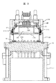
- FIG. 3 is a cross-sectional view illustrating a method of fixing a circuit board and a substrate support of the electric power steering device shown in FIG. 2.
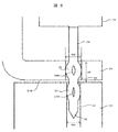
- FIG. 4 is an enlarged sectional view of a part A shown in the electric power steering device shown in FIG. 3.
- FIG. 3 is a cross-sectional view illustrating a method of fixing a housing and a substrate support of the electric power steering device shown in FIG. 2.
- FIG. 6 is an enlarged sectional view of a portion B shown in the electric power steering device shown in FIG.
- the steering device 1 is configured as shown in FIG.
- a pinion (not shown) is provided at a lower end of the steering shaft 2 connected to a steering wheel (not shown), and this pinion is engaged with a rack (not shown) which is long in the left-right direction of the vehicle body.
- Tie rods 3 for steering the front wheels in the left-right direction are connected to both ends of the rack, and the rack is covered by a rack housing 4.
- a rubber boot 5 is provided between the rack housing 4 and the tie rod 3.
- An electric power steering device 6 is provided to assist the torque when rotating the steering wheel. That is, a torque sensor 7 for detecting a turning direction and a turning torque of the steering shaft 2 is provided, and an electric motor unit 8 for applying a steering assist force to the rack via the gear 10 based on a detection value of the torque sensor 7. And an electronic control unit (ECU) 9 for controlling the electric motor disposed in the electric motor unit 8.
- the electric motor unit 8 of the electric power steering device 6 has an outer peripheral portion on the output shaft side connected to the gear 10 via a screw (not shown), and an electronic control unit on the opposite side to the output shaft of the electric motor 8 portion. 9 are provided.
- the torque sensor 7 determines the rotation direction and the rotation torque of the steering shaft 2.
- the electronic control unit 9 calculates the driving operation amount of the electric motor based on the detected value.
- the electric motor is driven by the power switching element of the electronic control unit 9 based on the calculated drive operation amount, and the output shaft of the electric motor is rotated so as to drive the steering shaft 2 in the same direction as the operation direction.
- the rotation of the output shaft of the electric motor is transmitted from a pinion (not shown) to a rack (not shown) via a gear 10 to steer the vehicle. Since these configurations and operations are already well known, further description will be omitted.
- the tip of a metal press-fit type connector terminal insert-molded in a connector body made of a synthetic resin has a through-hole formed in a circuit board. And is elastically engaged with and fixed to.
- the circuit board and the housing are generally fastened by fixing screws. In this case, the circuit board is screwed and fixed to the housing with the fixing screws, and then the press-fit connector terminals are connected to the circuit board through holes. And is elastically engaged with and fixed to.
- the embodiment of the present invention proposes an electric power steering device having the following configuration.
- a first terminal engagement hole is provided in a circuit board, and a second terminal engagement hole is provided in a substrate support that is disposed adjacent to the circuit board and supports the circuit board;
- a first elastic engagement portion that elastically engages the first terminal engagement hole with the press-fit type connector terminal; and a first elastic engagement portion that elastically engages the second terminal engagement hole adjacent to the first elastic engagement portion.
- the first elastic engaging portion is connected to the first elastic engaging portion while the press-fit connector terminal is inserted into the first terminal engaging hole and the second terminal engaging hole.
- the second elastic engaging portion is elastically engaged with the second terminal engaging hole, whereby the circuit board and the substrate support are integrally fixed.
- a first terminal engagement hole is provided in a substrate support on which a circuit board is supported, and a second terminal engagement hole is provided in a fixing portion disposed adjacent to the substrate support.
- a first elastic engagement portion elastically engaged with the first terminal engagement hole, and a first elastic engagement portion elastically engaged with the second terminal engagement hole adjacent to the first terminal engagement hole.
- a second elastic engaging portion that fits with the first elastic engaging portion in a state where the press-fit connector terminal is inserted into the first terminal engaging hole and the second terminal engaging hole.
- the second elastic engagement portions are elastically engaged with the second terminal engagement holes, and the substrate support and the fixed portion are integrally formed. To be fixed.
- the circuit board and the substrate support can be fixed by the press-fit connector terminal, or the housing and the substrate support can be fixed by the press-fit connector terminal.
- the electrical connection of the press-fit connector terminals and the indirect or direct fixing of the circuit board can be realized with a simple configuration.
- FIGS. 3 and 4 show cross sections of a fixed portion between the circuit board and the substrate support
- FIGS. 2 shows a cross section of a fixed part of the body and the substrate support.
- FIGS. 3 and 4 show examples in which the circuit board is directly fixed to the substrate support
- FIGS. 5 and 6 show that the circuit board is indirectly fixed to the housing via the substrate support. An example is shown.
- the electric motor unit 8 constituting the electric power steering device includes a motor housing 11 having a cylindrical portion made of aluminum or an aluminum-based metal such as an aluminum alloy, and a housing (not shown) housed in the motor housing 11. And an electric motor.
- the electric motor has a rotating shaft, and a pinion (not shown) is fixed to an output portion of the rotating shaft to transmit a rotating motion to the rack.
- the axis of the rotating shaft and the axis of the motor housing 11 substantially coincide with each other, and the electric motor can rotate inside the motor housing 11.
- the electronic control unit 9 is disposed on the opposite side to the output unit (pinion side) in the axial direction of the motor housing 11, and has a bottomed cylindrical (so-called cup-shaped) cover 12 (not shown) (not shown). (Made of metal). Thereby, the electronic control unit 9 has a liquid-tight structure.
- a socket 13 is formed on the side opposite to the motor housing 11.
- the socket 13 is provided with power supply-side sockets 13A and 13B connected to a power supply (battery) and sensors such as a steering angle sensor or a sensor / network-side socket connected to a CAN network.
- the power supply-side socket portions 13A and 13B are provided in pairs (two), and these are redundant sockets. The redundant system will be described later.
- a motor housing 11 is made of an aluminum alloy, and functions as a heat sink member that releases heat generated by an electric motor and heat generated by a power supply circuit unit and a power conversion circuit unit described later to the outside atmosphere. I have.
- the electric motor section 8 is constituted by the electric motor and the motor housing 11.
- the electronic control unit 9 is attached to the end wall 15 of the motor housing 11 on the opposite side of the pinion of the electric motor unit 8.
- the end wall 15 functions as a “housing” to which the electronic control unit 9 is attached.
- the electronic control section 9 includes a power conversion circuit board 16S having a power conversion circuit section mounted thereon, a power supply circuit board 17S having a power supply circuit section mounted thereon, a control circuit board 18S having a control circuit section mounted thereon, and a connector body 14. .
- circuit boards 16S, 17S, 18S are assembled in a state where they are stacked in a parallel relationship. It should be noted that the electronic components and electric components constituting the respective circuit units are not shown on the power conversion circuit board 16S, the power supply circuit board 17S, and the control circuit board 18S.
- the end wall 15 of the motor housing 11 is formed separately from the end wall 15 and is integrated with the motor housing 11 by screws or welding. It may be formed integrally by cutting.
- the power conversion circuit section, the power conversion circuit section, and the control circuit section constitute a redundant system, and constitute a dual system of the first electronic control section and the second electronic control section.
- the electric motor is controlled and driven by the first electronic control unit.
- the electric motor is switched to the second electronic control unit to control and drive the electric motor. It is something that comes to come.
- heat from the first electronic control unit is transmitted to the motor housing 11, and when an abnormality or failure occurs in the first electronic control unit, the first electronic control unit stops and the second electronic control unit operates. The heat from the second electronic control unit is transmitted to the motor housing 11.
- the first electronic control unit and the second electronic control unit are combined to function as a regular electronic control unit. If an abnormality or failure occurs in one of the electronic control units, the other electronic control unit uses an electric motor with half the capacity. Can be controlled and driven. In this case, the capacity of the electric motor is halved, but the so-called “power steering function” is ensured. Therefore, in a normal case, the heat of the first electronic control unit and the second electronic control unit is transmitted to the motor housing 11. In the present embodiment, the latter redundant system is adopted, and therefore, the power supply side socket portions 13A and 13B are provided in pairs.
- the electronic control unit 9 includes a power conversion circuit board 16S, a power supply circuit board 17S, a control circuit board 18S, and a connector main body 14, and the power is controlled in a direction away from the end wall 15 side.
- the conversion circuit board 16S, the power supply circuit board 17S, the board supports 21A and 21B, the control circuit board 18S, and the connector body 14 are arranged in this order and in a stacked state.
- the control circuit unit mounted on the control circuit board 18S has a function of generating a control signal for driving a switching element (MOSFET) of the power conversion circuit board 16S, and includes a microcomputer, peripheral circuits, and the like.
- MOSFET switching element
- the power supply circuit section mounted on the power supply circuit board 17S generates a power supply voltage for driving the control circuit section mounted on the control circuit board 18S and a power supply voltage for driving the power conversion circuit mounted on the power conversion circuit board 16S. It has a function to perform the operation, and includes a capacitor, a coil, a switching element, and the like.
- the power conversion circuit unit mounted on the power conversion circuit board 16S has a function of adjusting the power flowing through the motor winding of the electric motor, and includes switching elements and the like forming three-phase upper and lower arms.
- the electronic control unit 9 generates a large amount of heat mainly in the power conversion circuit unit and the power supply circuit unit, and heat of the power conversion circuit unit and the power supply circuit unit is radiated from the motor housing 11 mainly made of an aluminum alloy. Things.
- a connector body 14 made of a synthetic resin is provided between the control circuit board 18S and the cover, and is connected to a vehicle power supply (battery) and an external control device (not shown). Needless to say, the connector body 14 is electrically connected to the power conversion circuit board 16S, the power supply circuit board 17S, and the control circuit board 18S.
- the cover 12 accommodates the power conversion circuit board 16S, the power supply circuit board 17S, and the control circuit board 18S, and has a function of sealing them in a liquid-tight manner.
- the cover 12 is fixed to the motor housing 11. Have been.
- a power conversion circuit board 16S constituting a power conversion circuit is provided on the surface of the end wall 15 of the motor housing 11, and a switching element and the like are surface-mounted on the power conversion circuit board 16S.
- the power conversion circuit board 16 ⁇ / b> S is screwed and fixed to the end wall 15 by four fixing screws 19.
- the power conversion circuit board 16S is desirably formed of a metal substrate, so that heat generated by the switching element or the like can be efficiently radiated to the end wall 15.
- a metal substrate such as a glass epoxy substrate, and in this embodiment, it is made of a glass epoxy substrate.
- a projecting fixing portion 20 functioning as a part of a housing extending in a direction away from the end wall portion 15 in the direction of the rotation axis of the electric motor is formed. Functions as an electrical ground.
- the projecting fixing portions 20 are formed at an angle of 180 ° so as to face each other.
- the protrusion fixing portion 20 has a function of fixing a substrate support 21B made of a conductive metal having a function of fixing a substrate.
- the space formed by the protruding fixing portion 20 has a function of accommodating a switching element and the like constituting the power conversion circuit portion. Further, a terminal engagement hole 22 into which a press-fit connector terminal described later is inserted is formed on the upper surface side of the protruding fixing portion 20.
- the power supply circuit board 17S is made of a glass epoxy board, and board supports 21A are fixed at four corners with fixing screws. In addition, a pair of cutouts are formed which retreat inward in the radial direction and face each other. The notch has a function for accommodating one of the substrate supports 21B. Further, a terminal engagement hole 23 into which a press-fit type connector terminal described later is inserted is formed in the substrate support 21B.
- the flexible connector is a connection connector that can be bent freely, and can connect the power conversion circuit board 16S and the power supply circuit board 17S with the power conversion circuit board 16S and the power supply circuit board 17S arranged in parallel.
- the substrate support 21A made of a conductive metal is fixed to the power supply circuit board 17S at four corners with fixing screws 24, and is fixed to the opposite corners of the control circuit board 18S.
- the control circuit board 17 has a terminal engagement hole 25 into which a press-fit connector terminal described later is inserted.
- the board support 21A on the control circuit board 17S side also has a terminal engagement hole (see FIG. 4) into which a later-described press-fit connector terminal is inserted.
- the substrate support 21A is formed in a U-shape, one of which is fixed to the power supply circuit board 17S by a fixing screw 24, and the other is a press-fit type with the control circuit board 18S. Fixed with connector terminals.
- the substrate support 21B is formed in a deformed “S” shape, one of which is fixed to the protruding fixing portion 20 by a press-fit type connector terminal, and the other is in contact with the control circuit board 18S, and
- the control circuit board 18S is supported by being fixed to the board 18S with an adhesive or the like.
- the board support 21B is disposed between the board supports 21A described above, and suppresses the control circuit board 18S from bending near the center, thereby improving the reliability of the control circuit board 17S.
- the control circuit board 18S is made of a glass epoxy board, and the power supply circuit board 17S and the control circuit board 18S are connected by the flexible connector 26 so that the power conversion circuit board 16S and the power supply circuit board 17S are connected by the flexible connector. It is connected.
- the connector body 14 is disposed on the control circuit board 18S.
- the connector body 14 is made of a synthetic resin, and press-fit type connector terminals are embedded by insert molding.
- the press-fit type connector terminal includes a power supply side connector terminal connected to a power supply, a steering angle sensor and a rotation sensor, a sensor / network side connector terminal connected to a CAN network, a ground terminal, and the like.
- the power supply side connector terminal is also configured as a redundant system.
- Steps are formed at the four corners of the connector body 14, and press-fit type connector terminals 27 are embedded in the steps, and a part thereof is arranged so as to be exposed to the outside.
- the above-described press-fit type connector terminal 27 has a flat plate shape, and has two elastic engaging portions formed at the tip end side.
- the terminal engaging hole (see FIG. 4) is elastically engaged.
- the press-fit type connector terminals are also elastically provided in the terminal engagement holes 23 formed in the substrate support 21B and the terminal engagement holes 22 formed in the protruding fixing portion 20. Are engaged.
- FIG. 3 is a cross-sectional view taken along the rotation axis direction so as to pass through the substrate support 21A.
- the press-fit type connector terminal 27 is a terminal for grounding, and is a terminal for grounding electronic components and electric components mounted on the control circuit board 18S.
- the press-fit connector terminal 27 is connected to a press-fit connector terminal 34 shown in FIGS. 5 and 6 described later, and is connected inside the connector body 14. Specifically, the press-fit connector terminals 27 and the press-fit connector terminals 34 are integrally formed by punching. Further, since the press-fit connector terminals 27 and the press-fit connector terminals 34 need to have a mechanical fixing function, the thickness is determined to be a thickness satisfying the fixing function.
- the control circuit board 18S is disposed adjacent to the board support 21A when viewed in the axial direction of the motor housing, and has a terminal engagement hole 25 of the control circuit board 18S and a terminal engagement hole of the board support 21A.
- the positions of the control circuit board 18S and the substrate support 21A are determined such that the positions shown in FIG. 4 overlap each other.
- the press-fit type connector terminals 27 are inserted into the respective terminal engaging holes, and engage with the elastic engaging portions of the press-fit type connector terminals 27 to mechanically connect the control circuit board 18S and the board support 21A. And the press-fit connector terminal 27 and the control circuit board 18S are electrically connected.
- FIG. 4 shows an enlarged cross section of the portion A in FIG.
- a terminal engagement hole 25 functioning as a through hole is formed in a control circuit board 18S made of a glass epoxy board.
- a land 28 made of a conductive metal is formed in the terminal engagement hole 25, and the land 28 is connected to an electronic component or an electric component (not shown).
- a terminal engaging hole 29 is formed in the substrate support 21A made of metal.
- the center lines of the terminal engagement holes 25 and the terminal engagement holes 29 are respectively coincident. Therefore, the press-fit type connector terminal 27 can be inserted smoothly.
- the diameter of the terminal engagement hole 29 of the board support 21A is set to a value smaller than the diameter of the terminal engagement hole 25 of the control circuit board 18S. The reason will be described later.
- An insulating sheet 30 is interposed between the control circuit board 18S and the board support 21A to electrically insulate them. However, if there is a sufficient gap between the control circuit board 18S and the board support 21A, the insulating sheet 30 is not always necessary.
- the press-fit type connector terminal 27 is formed in an elongated flat plate shape, and has a pointed end portion 31 formed in a pointed shape on the distal end side.
- a support-side elastic engaging portion 32 having a large width from the front end side and a substrate-side elastic engaging portion 33 having a large width also are formed.
- the support-side elastic engagement portion 32 is elastically engaged with the terminal engagement hole 29 of the substrate support 21A, and similarly, the substrate-side elastic engagement portion 33 is elastically engaged with the terminal engagement hole 25 of the control circuit board 18S. Engaged.
- the two elastic engaging portions 32 and 33 are also formed adjacent to each other in accordance with the arrangement of the control circuit board 18S and the board support 21A. For this reason, the distance between the control circuit board 18S and the board support 21A is shortened, the bending moment acting on each other is not increased, and the reliability of the mechanical fixing function can be improved.
- Openings 32H and 33H are formed at the center of the respective elastic engaging portions 32 and 33.
- the areas of the openings 32H and 33H are elastically deformed and elastically deform in a direction orthogonal to the insertion direction. Give power.
- a predetermined holding force mainly a frictional force
- the width WA of the support-side elastic engagement portion 32 is set to a length corresponding to the terminal engagement hole 29 of the substrate support 21A
- the width WS of the substrate-side elastic engagement portion 33 is also set to the control circuit board 18S.
- the length is set in accordance with the terminal engagement hole 25 of FIG. That is, the widths WA and WS of the respective elastic engagement portions 32 and 33 are set to a predetermined value when the respective elastic engagement portions 32 and 33 are elastically engaged with the respective terminal engagement holes 29 and 25. It is determined so that a force (mainly frictional force) can be obtained.
- the diameter of the terminal engagement hole 29 of the board support 21A is set to a value smaller than the diameter of the terminal engagement hole 25 of the control circuit board 18S. The reason is as follows. That is, when the press-fit type connector terminal 27 is inserted from the control circuit board 18S side, the terminal engagement hole 25 of the control circuit board 18S is first inserted by the support side elastic engagement portion 32.
- the terminal engagement hole 25 is set smaller, the width WA of the support-side elastic engagement portion 32 of the press-fit connector terminal 27 is large. 32 cannot be inserted well.
- the press-fit type connector terminal 27 is inserted from the side of the substrate support 21A, the relationship is reversed.
- the length of the board-side elastic engaging portion 33 is determined in accordance with the axial length LS of the terminal engaging hole 25 of the control circuit board 18S.
- the length LA of the support-side elastic engaging portion 32 is determined according to the length LS in the direction. Therefore, in order to increase the holding force, the lengths LS, LA of the respective terminal engagement holes 25, 29 can be increased, and similarly, the lengths of the respective elastic engagement portions 32, 33 can be increased. is there.
- press-fit type connector terminal 27 is for a ground terminal
- a press-fit type connector terminal which will be described later, is connected to the ground terminal of the control circuit board 18S via the land 28 and the board-side elastic engaging portion 33.
- An earth circuit is formed toward.
- the control circuit board 18S and the substrate-side elastic engagement portion 33 are elastically engaged and fixed.
- the control circuit board 18S can be fixed to the board support 21A without using fixing screws or the like. Further, since the press-fit type connector terminals 27 are merely inserted into the terminal engagement holes 25 and 29 of the control circuit board 18S and the board support 21A, the number of working steps such as forming fixing screws can be reduced.
- the press-fit type connector terminal 27 is used for the ground terminal.
- the press-fit type connector terminal 27 is used only for fixing the control circuit board 18S and the board support 21A without passing a current. Of course, it is possible.
- the power supply circuit board 17S is used instead of the control circuit board 18S, it is possible to use only the press-fit type connector terminal 27 and use it as a power supply connector terminal.
- the current from the power supply is supplied to the power supply circuit of the power supply circuit board 17S via the press-fit type connector terminal 27, and the board support 21A and the power supply circuit board 17S are fixed to each other by the press-fit type connector terminal 27. .
- the substrate support 21A and the support-side elastic engaging portion 32 are elastically engaged and fixed, and the control circuit board 18S and the substrate-side elastic engaging portion 33 are elastically engaged and fixed. Therefore, the control circuit board 18S can be fixed without using fixing screws or the like for the substrate support 21A. Further, since the press-fit type connector terminals 27 are merely inserted into the terminal engagement holes 25 and 29 of the control circuit board 18S and the board support 21A, the number of working steps such as formation of fixing screws can be reduced.
- FIG. 5 is a cross-sectional view taken along the rotation axis direction so as to pass through the substrate support 21B.
- the press-fit type connector terminal 34 is a terminal for grounding, and is a terminal for grounding an electronic component or an electrical component mounted on the control circuit board 18S to the protruding fixing portion 20.
- the bent fixing portion of the substrate support 21B is disposed adjacent to the protruding fixing portion 20 which is a housing, and has a terminal engaging hole 23 of the substrate supporting member 21B and a terminal engaging hole 22 of the protruding fixing portion 20.
- the positions of the substrate support 21 ⁇ / b> B and the protruding fixing part 20 are determined so that the two overlap.
- the press-fit type connector terminal 34 is inserted into each of the terminal engagement holes 22 and 23, and engages with the elastic engagement portion of the press-fit type connector terminal 34, so that the board support 21B and the protrusion fixing portion 20 Are mechanically fixed, and the press-fit connector terminal 34 and the protruding fixing portion 20 are electrically connected.
- the protrusion fixing portion 20 is grounded to the motor housing 11.
- FIG. 6 shows an enlarged cross section of a portion B in FIG.
- a terminal engaging hole 23 is formed in a bent fixing portion 35 of a substrate support 21B made of metal.
- a terminal engaging hole 22 is formed in the protruding fixing portion 20 made of a conductive metal.
- the center lines of the terminal engaging hole 23 and the terminal engaging hole 22 are respectively coincident. Therefore, the press-fit type connector terminal 34 can be smoothly inserted.
- the diameter of the terminal engagement hole 23 is set to a value smaller than the diameter of the terminal engagement hole 22. The reason will be described later.
- Press-fit connector terminals 34 that mechanically fix the substrate support 21B and the protruding fixing portion 20 and that are electrically connected to the protruding fixing portion 20 are inserted through the respective terminal engaging holes 23 and 22. I have.
- the press-fit type connector terminal 34 is formed in an elongated flat plate shape, and has a pointed portion 36 formed in a pointed shape on the distal end side.
- a fixed portion side elastic engagement portion 37 and a support body side elastic engagement portion 38 are formed from the pointed end side.
- the fixed portion side elastic engaging portion 37 is elastically engaged with the terminal engaging hole 22 of the projecting fixing portion 20, and similarly, the support side elastic engaging portion 38 is elastically engaged with the terminal engaging hole 23 of the substrate support 21B. Is engaged.
- the two elastic engaging portions 37 and 38 are also formed adjacent to each other in accordance with the arrangement of the projecting fixing portion 20 and the substrate support 21A. For this reason, the distance between the projecting fixing portion 20 and the substrate support 21A is shortened, the bending moment acting on each other is not increased, and the reliability of mechanical fixing can be improved.
- Openings 37H and 38H are formed at the center of the respective elastic engaging portions 37 and 38.
- the areas of the openings 32H and 33H are elastically deformed and elastically deform in a direction orthogonal to the insertion direction. Give power. Thereby, a predetermined holding force (mainly a frictional force) is obtained.
- the width WE of the fixed portion side elastic engagement portion 37 is set to a length corresponding to the terminal engagement hole 22 of the projecting fixed portion 20, and the width WB of the support side elastic engagement portion 38 is The length is set in accordance with the terminal engagement hole 23 of 21B. That is, the widths WE and WB of the respective elastic engagement portions 37 and 38 are such that a predetermined holding force (mainly a frictional force) is obtained when the elastic engagement portions 37 and 38 are elastically engaged with the respective terminal engagement holes 22 and 23. It is decided to.
- a predetermined holding force mainly a frictional force
- the diameter of the terminal engaging hole 22 of the protruding fixing portion 20 is set to a value smaller than the diameter of the terminal engaging hole 23 of the substrate support 21B.
- the reason is as follows. That is, when the press-fit type connector terminal 34 is inserted from the substrate support 21B side, the terminal engaging hole 23 of the substrate support 21B is first inserted by the fixed portion side elastic engaging portion 37. For this reason, when the terminal engagement hole 23 is set smaller, the width WE of the fixed portion side elastic engagement portion 37 of the press-fit type connector terminal 34 is large, so that the fixed portion side elastic engagement portion This is because the joint 37 cannot be inserted properly.
- the length of the support-side elastic engaging portion 38 is determined in accordance with the axial length LB of the terminal engaging hole 23 of the substrate support 21B.
- the length of the fixed portion side elastic engagement portion 37 is determined according to the length. Note that the length of the fixed portion side elastic engagement portion 37 can be determined to any length as long as it is within the length of the protruding fixed portion 20. Therefore, in order to increase the holding force, the lengths LS, LA of the respective terminal engagement holes 25, 29 can be increased, and similarly, the lengths of the respective elastic engagement portions 32, 33 can be increased. is there.
- the press-fit type connector terminal 34 is for an earth terminal
- an earth circuit is formed from the press-fit type connector terminal 27 to the projecting fixing part 20 via the fixing part side elastic engaging part 37.
- the protruding fixing portion 20 and the fixing portion side elastic engaging portion 37 are elastically engaged and fixed, and similarly, the substrate support 21B and the support side elastic engaging portion 38 are elastically engaged and fixed. Therefore, the substrate support 21B can be fixed to the protruding fixing portion 20 without using a fixing screw or the like.
- the press-fit type connector terminal 34 is merely inserted into the board support 21B and the terminal engaging holes 22 and 23 of the protruding fixing part 20, the number of manufacturing steps such as formation of fixing screws can be reduced.
- the press-fit type connector terminal 34 is used for the ground terminal.
- the press-fit type connector terminal 34 may be used merely for fixing the substrate support 21B and the protruding fixing portion 20 without passing an electric current. it can.
- the configuration in which the substrate support 21A and the substrate support 21B are separated is shown.
- the substrate support 21A and the substrate support 21B are integrated to form an annular substrate support.
- the electronic component and the electrical component that constitute the power supply circuit may be housed in a space formed inside.
- a control circuit board is arranged on the upper surface side of the substrate support (annular) and fixed with press-fit connector terminals
- a power supply circuit board is arranged on the lower surface side of the substrate support (annular) and fixed with screws.
- the substrate support and the protruding fixing portion may be fixed by press-fit connector terminals.
- the first terminal engagement hole is provided in the circuit board
- the second terminal engagement hole is provided in the substrate support that is disposed adjacent to the circuit board and supports the circuit board.
- a first elastic engagement portion elastically engaged with the first terminal engagement hole
- a first elastic engagement portion elastically engaged with the second terminal engagement hole adjacent to the first terminal engagement hole.
- a second elastic engaging portion that fits with the first elastic engaging portion in a state where the press-fit connector terminal is inserted into the first terminal engaging hole and the second terminal engaging hole.
- the second elastic engagement portions are elastically engaged with the second terminal engagement holes, and the circuit board and the substrate support are integrally formed. To be fixed.
- the first terminal engagement hole is provided in the substrate support on which the circuit board is supported, and the second terminal engagement hole is provided in the fixing portion arranged adjacent to the substrate support.
- a first elastic engagement portion elastically engaged with the first terminal engagement hole, and a first elastic engagement portion elastically engaged with the second terminal engagement hole adjacent to the first terminal engagement hole.
- a second elastic engaging portion that fits with the first elastic engaging portion in a state where the press-fit connector terminal is inserted into the first terminal engaging hole and the second terminal engaging hole.
- the second elastic engagement portions are elastically engaged with the second terminal engagement holes, and the substrate support and the fixed portion are integrally formed. To be fixed.
- the circuit board and the substrate support can be fixed by the press-fit connector terminal, or the housing and the substrate support can be fixed by the press-fit connector terminal.
- the electrical connection of the press-fit connector terminals and the indirect or direct fixing of the circuit board can be realized with a simple configuration.
- the present invention is not limited to the above-described embodiment, but includes various modifications.
- the above-described embodiments have been described in detail in order to explain the present invention in an easy-to-understand manner, and are not necessarily limited to those having all the described configurations.
- a part of the configuration of one embodiment can be replaced with the configuration of another embodiment, and the configuration of one embodiment can be added to the configuration of another embodiment.
Landscapes
- Engineering & Computer Science (AREA)
- Power Engineering (AREA)
- Chemical & Material Sciences (AREA)
- Combustion & Propulsion (AREA)
- Transportation (AREA)
- Mechanical Engineering (AREA)
- Microelectronics & Electronic Packaging (AREA)
- Power Steering Mechanism (AREA)
Abstract
回路基板18Sが支持される基板支持体21Aに第1の端子係合孔29が設けられ、基板支持体21Aに隣接して配置された回路基板18Sに第2の端子係合孔25が設けられ、プレスフィット型コネクタ端子27に、第1の端子係合孔29に弾性的に係合する第1の弾性係合部32と、第2の端子係合孔25に弾性的に係合する第2の弾性係合部33とが形成され、プレスフィット型コネクタ端子27が第1の端子係合孔29、及び第2の端子係合孔25に挿入された状態で、第1の弾性係合部32が第1の端子係合孔29に弾性的に係合され、第2の弾性係合部33が第2の端子係合孔25に弾性的に係合されて、回路基板18Sと基板支持体21Aとが一体的に固定される。これらの構成によって、プレスフィット型コネクタ端子の電気的な接続と、回路基板の固定(直接的固定、及び間接的固定を含む)を簡単に行うことができる。
Description
本発明は、電動駆動装置及び電動パワーステアリング装置に係り、特に電子制御部を内蔵した電動駆動装置及び電動パワーステアリング装置に関するものである。
一般的な産業機械分野においては、電動モータによって機械系制御要素を駆動することが行われているが、最近では電動モータの回転速度や回転トルクを制御する半導体素子等からなる電子制御部を電動モータに一体的に組み込む、いわゆる機電一体型の電動駆動装置が採用され始めている。
機電一体型の電動駆動装置の例として、例えば自動車の電動パワーステアリング装置においては、運転者がステアリングホィールを操作することにより回動するステアリングシャフトの回動方向と回動トルクとを検出し、この検出値に基づいてステアリングシャフトの回動方向と同じ方向へ回動するように電動モータを駆動し、操舵アシストトルクを発生させるように構成されている。この電動モータを制御するため、電子制御部(ECU:Electronic Control Unit)がパワーステアリング装置に設けられている。
従来の電動パワーステアリング装置としては、例えば、特開2016-144380号公報(特許文献1)に記載のものが知られている。この特許文献1には、電動モータ部と電子制御部とにより構成された電動パワーステアリング装置が記載されている。そして、電動モータ部の電動モータは、アルミ合金等から作られた筒部を有するモータハウジングに形成された収納空間に収納され、電子制御部の電子部品が実装された回路基板は、モータハウジングの軸方向の出力軸とは反対側の端面壁部に、合成樹脂製、或いは金属製のカバーによって形成された収納空間に収納されている。
モータハウジングの端面壁部に取り付けられる電子制御部の回路基板は、電動モータを駆動制御するMOSFET、或いはIGBT等のようなパワースイッチング素子を有する電力変換回路部、電源電圧を生成する電源回路部、及びパワースイッチング素子を制御する制御回路部を備え、パワースイッチング素子の出力端子と電動モータの入力端子とはバスバーを介して電気的に接続されている。
そして、電子制御部には、合成樹脂からなるコネクタ本体を介してバッテリ電源から電力が供給され、また、検出センサ類から運転状態等の検出信号が供給されている。コネクタ本体はカバーと一体的に形成されて蓋体として機能しており、電子制御部を密閉して塞ぐように接着剤によって端面壁部の外周表面に固定されている。また、コネクタ本体とカバーを別体に形成し、コネクタ本体をカバーで覆う形態とされている場合もある。
また、コネクタ本体から突出したコネクタ端子は、電子制御部の回路基板に接続される必要があるが、接続を単純化するためにプレスフィット型コネクタ端子を用いることが提案されている。例えば、特開2016-127780号公報(特許文献2)には、回路基板にスルーホールを形成し、このスルーホールにプレスフィット型コネクタ端子の先端側に形成した弾性係合部を挿入することで、回路基板とプレスフィット型コネクタ端子を電気的に接続している。これによって、コネクタ端子を回路基板のスルーホールに挿入する工程だけで、簡単に電気的な接続を得ることができる。
尚、この他に電子制御部を一体化した電動駆動装置としては、電動ブレーキや各種油圧制御用の電動油圧制御器等が知られているが、以下の説明では代表して電動パワーステアリング装置について説明する。
ここで、特許文献2にあるような構成の電子制御部においては、合成樹脂からなるコネクタ本体にインサートモールドされた金属製のプレスフィット型コネクタ端子は、電源(バッテリ)と接続コードを介して接続されている。そして、このプレスフィット型コネクタ端子の先端側は、回路基板に設けられたスルーホールに弾性的に係合されている。また、回路基板と筐体は一般的に固定ねじによって締結されており、この場合は、回路基板を固定ねじによって筐体とねじ止め固定し、その後にプレスフィット型コネクタ端子が回路基板のスルーホールに弾性的に係合されている。
このため、回路基板に固定ねじが挿通する大径の貫通孔を形成し、更に筐体にねじ孔を形成することが必要であり、回路基板の大型化や、ねじ加工による製造コストの高騰といった課題があった。また、これに伴って作業工数も増えることになる。したがって、この種の電動駆動装置においては、プレスフィット型コネクタ端子の電気的な接続や、回路基板の固定(直接的固定、及び間接的固定を含む)を簡単な構成で実現できる技術が要請されている。
本発明の目的は、プレスフィット型コネクタ端子の電気的な接続や、回路基板の固定(直接的固定、及び間接的固定を含む)を簡単に行うことができる新規な電動駆動装置及び電動パワーステアリング装置を提供することにある。
本発明の第1の特徴は、回路基板に第1の端子係合孔が設けられ、回路基板に隣接して配置され回路基板を支持する基板支持体に第2の端子係合孔が設けられ、プレスフィット型コネクタ端子に、第1の端子係合孔に弾性的に係合する第1の弾性係合部と、これに隣接して第2の端子係合孔に弾性的に係合する第2の弾性係合部とが形成され、プレスフィット型コネクタ端子が第1の端子係合孔、及び第2の端子係合孔に挿入された状態で、第1の弾性係合部が第1の端子係合孔に弾性的に係合され、第2の弾性係合部が第2の端子係合孔に弾性的に係合されて、回路基板と基板支持体とが一体的に固定される、ところにある。
本発明の第2の特徴は、回路基板が支持される基板支持体に第1の端子係合孔が設けられ、基板支持体に隣接して配置された固定部に第2の端子係合孔が設けられ、プレスフィット型コネクタ端子に、第1の端子係合孔に弾性的に係合する第1の弾性係合部と、これに隣接して第2の端子係合孔に弾性的に係合する第2の弾性係合部とが形成され、プレスフィット型コネクタ端子が第1の端子係合孔、及び第2の端子係合孔に挿入された状態で、第1の弾性係合部が第1の端子係合孔に弾性的に係合され、第2の弾性係合部が第2の端子係合孔に弾性的に係合されて、基板支持体と固定部とが一体的に固定される、ところにある。
本発明によれば、プレスフィット型コネクタ端子によって、回路基板と基板支持体を固定することができる、或いはプレスフィット型コネクタ端子によって、筐体と基板支持体を固定することができるので、プレスフィット型コネクタ端子の電気的な接続と、回路基板の間接的、或いは直接的な固定を簡単な構成で実現できる。
以下、本発明の実施形態について図面を用いて詳細に説明するが、本発明は以下の実施形態に限定されることなく、本発明の技術的な概念の中で種々の変形例や応用例をもその範囲に含むものである。
本発明の実施形態を説明する前に、本発明が適用される一例としての操舵装置の構成について図1を用いて簡単に説明する。
まず、自動車の前輪を操舵するための操舵装置について説明する。操舵装置1は図1に示すように構成されている。図示しないステアリングホイールに連結されたステアリングシャフト2の下端には図示しないピニオンが設けられ、このピニオンは車体左右方向へ長いラック(図示せず)と噛み合っている。このラックの両端には前輪を左右方向へ操舵するためのタイロッド3が連結されており、ラックはラックハウジング4に覆われている。そして、ラックハウジング4とタイロッド3との間にはゴムブーツ5が設けられている。
ステアリングホイールを回動操作する際のトルクを補助するため、電動パワーステアリング装置6が設けられている。即ち、ステアリングシャフト2の回動方向と回動トルクとを検出するトルクセンサ7が設けられ、トルクセンサ7の検出値に基づいてラックにギヤ10を介して操舵補助力を付与する電動モータ部8と、電動モータ部8に配置された電動モータを制御する電子制御部(ECU)9とが設けられている。電動パワーステアリング装置6の電動モータ部8は、出力軸側の外周部の3箇所が、図示しないねじを介してギヤ10に接続され、電動モータ8部の出力軸とは反対側に電子制御部9が設けられている。
電動パワーステアリング装置6においては、ステアリングホイールが操作されることによりステアリングシャフト2がいずれかの方向へ回動操作されると、このステアリングシャフト2の回動方向と回動トルクとをトルクセンサ7が検出し、この検出値に基づいて電子制御部9が電動モータの駆動操作量を演算する。この演算された駆動操作量に基づいて電子制御部9のパワースイッチング素子により電動モータが駆動され、電動モータの出力軸はステアリングシャフト2を操作方向と同じ方向へ駆動するように回動される。電動モータの出力軸の回動は、図示しないピニオンからギヤ10を介して図示しないラックへ伝達され、自動車が操舵されるものである。これらの構成、作用は既によく知られているので、これ以上の説明は省略する。
繰り返しなるが、特許文献2にあるような構成の電子制御部においては、合成樹脂からなるコネクタ本体にインサートモールドされた金属製のプレスフィット型コネクタ端子の先端は、回路基板に設けられたスルーホールに弾性的に係合、固定されている。また、回路基板と筐体は一般的に固定ねじによって締結されており、この場合は、回路基板を固定ねじによって筐体とねじ止め固定し、その後にプレスフィット型コネクタ端子が回路基板のスルーホールに弾性的に係合、固定されている。
このため、回路基板に固定ねじが挿通する大径の貫通孔を形成し、更に筐体にねじ孔を形成することが必要であり、回路基板の大型化や、ねじ加工による製造コストの高騰といった課題があった。
このような背景から、本発明の実施形態では次のような構成の電動パワーステアリング装置を提案するものである。
第1の実施形態においては、回路基板に第1の端子係合孔が設けられ、回路基板に隣接して配置され回路基板を支持する基板支持体に第2の端子係合孔が設けられ、プレスフィット型コネクタ端子に、第1の端子係合孔に弾性的に係合する第1の弾性係合部と、これに隣接して第2の端子係合孔に弾性的に係合する第2の弾性係合部とが形成され、プレスフィット型コネクタ端子が第1の端子係合孔、及び第2の端子係合孔に挿入された状態で、第1の弾性係合部が第1の端子係合孔に弾性的に係合され、第2の弾性係合部が第2の端子係合孔に弾性的に係合されて、回路基板と基板支持体とが一体的に固定される構成とした。
第2の実施形態においては、回路基板が支持される基板支持体に第1の端子係合孔が設けられ、基板支持体に隣接して配置された固定部に第2の端子係合孔が設けられ、プレスフィット型コネクタ端子に、第1の端子係合孔に弾性的に係合する第1の弾性係合部と、これに隣接して第2の端子係合孔に弾性的に係合する第2の弾性係合部とが形成され、プレスフィット型コネクタ端子が第1の端子係合孔、及び第2の端子係合孔に挿入された状態で、第1の弾性係合部が第1の端子係合孔に弾性的に係合され、第2の弾性係合部が第2の端子係合孔に弾性的に係合されて、基板支持体と固定部とが一体的に固定される構成とした。
このような実施形態によれば、プレスフィット型コネクタ端子によって、回路基板と基板支持体を固定することができる、或いはプレスフィット型コネクタ端子によって、筐体と基板支持体を固定することができるので、プレスフィット型コネクタ端子の電気的な接続と、回路基板の間接的、或いは直接的な固定を簡単な構成で実現できる。
次に、本発明の実施形態になる電動パワーステアリング装置の具体的な構成について、図2乃至図6を用いて詳細に説明する。
図2は電動パワーステアリング装置の電子制御部を分解して斜めから見たものであり、図3、図4は回路基板と基板支持体の固定部分の断面を示し、図5、図6は筐体と基板支持体の固定部分の断面を示している。ここで、図3、図4は回路基板が基板支持体に直接的に固定される例を示し、図5、図6は回路基板が基板支持体を介して筐体に間接的に固定される例を示している。
図2に示すように、電動パワーステアリング装置を構成する電動モータ部8は、アルミニウム、或いはアルミ合金等のアルミ系金属から作られた筒部を有するモータハウジング11、及びこれに収納された図示しない電動モータとから構成されている。電動モータは周知のように回転軸を備えており、この回転軸の出力部には図示しないピニオンが固定され、ラックに回転運動を伝えている。回転軸の軸心とモータハウジング11の軸心はほぼ一致しており、電動モータはモータハウジング11内で回転することができる。
また、電子制御部9は、モータハウジング11の軸方向の出力部(ピニオン側)とは反対側に配置されており、図示しない有底筒状(いわゆる、カップ状)のカバー12(合成樹脂や金属で作られている)によって収納されるように覆われている。これによって、電子制御部9は液密構造となっている。またモータハウジング11とは反対側には、ソケット部13が形成されている。
ソケット部13には、電源(バッテリ)に接続される電源側ソケット部13A、13Bと、舵角センサ等のセンサ類、或いはCANネットワークに接続されるセンサ/ネットワーク側ソケットとが形成されている。電源側ソケット部13A,13Bは対(2個)で設けられており、これらは冗長系のソケットとされている。冗長系については後述する。
次に電子制御部9の構成を説明する。図2において、モータハウジング11はアルミ合金から作られており、電動モータで発生した熱や、後述する電源回路部や電力変換回路部で発生した熱を外部大気に放出するヒートシンク部材として機能している。電動モータとモータハウジング11で電動モータ部8を構成している。
電動モータ部8のピニオンの反対側のモータハウジング11の端面壁部15には、電子制御部9が取り付けられている。尚、端面壁部15は電子制御部9が取り付けられる「筐体」として機能している。電子制御部9は、電力変換回路部を搭載した電力変換回路基板16S、電源回路部を搭載した電源回路基板17S、制御回路部を搭載した制御回路基板18S、及びコネクタ本体14から構成されている。
そして、これらの夫々の回路基板16S、17S、18Sは夫々が平行関係を有して積層された状態で組み立てられている。尚、電力変換回路基板16S、電源回路基板17S、制御回路基板18Sには、夫々の回路部を構成する電子部品や電気部品はその表示を省略している。
また、モータハウジング11の端面壁部15は、端面壁部15だけを別体に形成し、ねじや溶接によってモータハウジング11と一体化されているが、モータハウジング11と端面壁部15を鋳込みや切削で一体的に形成しても良い。
ここで、電力変換回路部、電力変換回路部、制御回路部は冗長系を構成するものであり、第1電子制御部と第2電子制御部の二重系を構成している。そして、通常は第1電子制御部によって電動モータが制御、駆動されているが、第1電子制御部に異常や故障が生じると、第2電子制御部に切り換えられて電動モータが制御、駆動されるようになるものである。
したがって、通常は第1電子制御部からの熱がモータハウジング11に伝えられ、第1電子制御部に異常や故障が生じると、第1電子制御部が停止して第2電子制御部が作動し、モータハウジング11には第2電子制御部からの熱が伝えられるものである。
また、第1電子制御部と第2電子制御部を合せて正規の電子制御部として機能させ、一方の電子制御部に異常、故障が生じると、他方の電子制御部で半分の能力によって電動モータを制御、駆動することも可能である。この場合、電動モータの能力は半分となるが、いわゆる「パワーステアリング機能」は確保されるようになっている。したがって、通常の場合は、第1電子制御部と第2電子制御部の熱がモータハウジング11に伝えられるものである。本実施形態は、後者の冗長系を採用しており、このため電源側ソケット部13A、13Bが対で設けられている。
図2にある通り、電子制御部9は、電力変換回路基板16S、電源回路基板17S、制御回路基板18S、コネクタ本体14から構成されており、端面壁部15側から離れる方向に向かって、電力変換回路基板16S、電源回路基板17S、基板支持体21A、21B、制御回路基板18S、コネクタ本体14の順序で、しかも積層される状態で配置されている。
制御回路基板18Sに搭載された制御回路部は、電力変換回路基板16Sのスイッチング素子(MOSFET)を駆動する制御信号を生成する機能を有するもので、マイクロコンピュータ、周辺回路等から構成されている。
電源回路基板17Sに搭載された電源回路部は、制御回路基板18Sに搭載された制御回路部を駆動する電源電圧、及び電力変換回路基板16Sに搭載された電力変換回路を駆動する電源電圧を生成する機能を有するもので、コンデンサ、コイル、スイッチング素子等から構成されている。
電力変換回路基板16Sに搭載された電力変換回路部は、電動モータのモータ巻線に流れる電力を調整する機能を有するもので、3相の上下アームを構成するスイッチング素子等から構成されている。
電子制御部9で発熱量が多いのは、主に電力変換回路部、電源回路部であり、電力変換回路部、電源回路部の熱は、主にアルミ合金からなるモータハウジング11から放熱されるものである。
制御回路基板18Sとカバーの間には、合成樹脂からなるコネクタ本体14が設けられており、車両電源(バッテリ)や外部の図示しない他の制御装置と接続されている。このコネクタ本体14は、電力変換回路基板16S、電源回路基板17S、制御回路基板18Sと電気的に接続されていることはいうまでもない。
カバー12は、電力変換回路基板16S、電源回路基板17S、制御回路基板18Sを収納し、これらを液密的に封止する機能を備えているものであり、本実施形態ではモータハウジング11に固定されている。
モータハウジング11の端面壁部15の表面には、電力変換回路部を構成する電力変換回路基板16Sが設けられており、これにスイッチング素子等が表面実装されている。電力変換回路基板16Sは、4個の固定ねじ19によって端面壁部15にねじ止め固定されている。
電力変換回路基板16Sは、望ましくは金属基板で形成されているのが良く、これによってスイッチング素子等で発生した熱を端面壁部15に効率良く放熱することができる。
もちろんガラスエポキシ基板で作られていても良いものであり、本実施形態ではガラスエポキシ基板で作られている。
もちろんガラスエポキシ基板で作られていても良いものであり、本実施形態ではガラスエポキシ基板で作られている。
モータハウジング11の端面壁部15の外周側の表面には、電動モータの回転軸の方向で端面壁部15から遠ざかる方向に延びる筐体の一部として機能する突出固定部20が形成されており、電気的なアースとして機能する。この突出固定部20は、互いに向き合うように180°の角度をもって形成されている。
この突出固定部20は、基板を固定する機能を備える導電性の金属で作られた基板支持体21Bを固定する機能を備えている。また、突出固定部20によって形成される空間は、電力変換回路部を構成するスイッチング素子等を収納する機能を備えている。更に、突出固定部20の上面側には、後述するプレスフィット型コネクタ端子が挿入される端子係合孔22が形成されている。
電源回路基板17Sはガラスエポキシ基板で作られており、四隅に基板支持体21Aが固定ねじによって固定されている。また、径方向で内側に後退し、互いに向き合う一対の切り欠き部が形成されている。この切り欠き部は、基板支持体21Bの一方を収納するための機能を備えている。更に、基板支持体21Bには、後述するプレスフィット型コネクタ端子が挿入される端子係合孔23が形成されている。
ここで、電力変換回路基板16Sと電源回路基板17Sとは、フレキシブルコネクタによって接続されている。フレキシブルコネクタは、自由な状態に湾曲できる接続コネクタであり、電力変換回路基板16Sと電源回路基板17Sを平行に配置した状態で、電力変換回路基板16Sと電源回路基板17Sを接続することができる。
導電性の金属から作られた基板支持体21Aは、四隅で電源回路基板17Sと固定ねじ24で固定されており、反対側に制御回路基板18Sの四隅と固定されている。制御回路基板17には、後述するプレスフィット型コネクタ端子が挿入される端子係合孔25が形成されている。また、ここでは図示していないが、制御回路基板17S側の基板支持体21Aにも、後述するプレスフィット型コネクタ端子が挿入される端子係合孔(図4参照)が形成されている。
詳しい説明は後述するが、基板支持体21Aにおいては、形状が「コ」状に形成されており、一方は固定ねじ24によって電源回路基板17Sと固定され、他方は制御回路基板18Sとプレスフィット型コネクタ端子で固定されている。また、基板支持体21Bは、形状が変形「S」状に形成されており、一方は突出固定部20とプレスフィット型コネクタ端子で固定され、他方は制御回路基板18Sと当接して、制御回路基板18Sと接着剤等によって固定されて、制御回路基板18Sを支持している。基板支持体21Bは、上述した基板支持体21Aの間に配置され、制御回路基板18Sが中央付近で撓むのを抑制して、制御回路基板17Sの信頼性を向上している。
また基板支持体21Aと基板支持体21Bによって形成された空間には、電源回路基板17Sに実装された電源回路を構成する電子部品や電気部品が収納される。また、基板支持体21A、21Bによる空間は、開放されているため、電源回路基板17Sに実装された電源回路で発生する熱を効率良く放熱することができる。
制御回路基板18Sはガラスエポキシ基板で作られており、電力変換回路基板16Sと電源回路基板17Sがフレキシブルコネクタによって接続されているように、電源回路基板17Sと制御回路基板18Sとはフレキシブルコネクタ26によって接続されている。
制御回路基板18Sの上には、コネクタ本体14が配置されている。コネクタ本体14は、合成樹脂で作られており、インサートモールドによってプレスフィット型コネクタ端子が埋設されている。プレスフィット型コネクタ端子は、電源に接続される電源側コネクタ端子や、舵角センサや回転センサ、或いはCANネットワークに接続されるセンサ/ネットワーク側コネクタ端子、アース端子等からなっている。ここで、電子制御部9は冗長系に構成されているので、電源側コネクタ端子も冗長系とされている。
コネクタ本体14の四隅には、段差部が形成されており、この段差部にプレスフィット型コネクタ端子27が埋設されており、その一部が外部に露出する形態で配置されている。
上述したプレスフィット型コネクタ端子27は平板状で、先端側に2個の弾性係合部が形成されており、制御回路基板18Sに形成した端子係合孔25と基板支持体21の他方に形成された端子係合孔(図4参照)に弾性的に係合されている。同様に、図面上では明確に表示されていないが、基板支持体21Bに形成した端子係合孔23、突出固定部20に形成された端子係合孔22にも、プレスフィット型コネクタ端子が弾性的に係合されている。
次に、このプレスフィット型コネクタ端子付近の詳細について説明する。図3は、基板支持体21Aを通るように、回転軸方向に断面した断面図である。プレスフィット型コネクタ端子27はアース用端子であり、制御回路基板18Sの上に搭載されている電子部品や電気部品をアース接続する端子である。
このプレスフィット型コネクタ端子27は、後述する図5、図6に示しているプレスフィット型コネクタ端子34と接続されており、コネクタ本体14の中で接続されている。具体的には、プレスフィット型コネクタ端子27とプレスフィット型コネクタ端子34とは、打ち抜き加工で一体的に形成されている。また、プレスフィット型コネクタ端子27とプレスフィット型コネクタ端子34は、機械的な固定機能を備える必要があることから、その厚さが固定機能を満足する仕様の厚さに決められている。
また、この制御回路基板18Sは、モータハウジングの軸方向で見て基板支持体21Aに隣接して配置されており、制御回路基板18Sの端子係合孔25と基板支持体21Aの端子係合孔(図4参照)が重なり合うように、制御回路基板18Sと基板支持体21Aの位置が決められている。そして、プレスフィット型コネクタ端子27が、夫々の端子係合孔に挿通され、プレスフィット型コネクタ端子27の弾性係合部と係合して、制御回路基板18Sと基板支持体21Aとを機械的に固定する共に、プレスフィット型コネクタ端子27と制御回路基板18Sとを電気的に接続している。
図4は、図3のA部の拡大断面を示している。図4において、ガラスエポキシ基板からなる制御回路基板18Sには、スルーホールとして機能する端子係合孔25が形成されている。端子係合孔25には、導電性の金属からなるランド28が形成されており、このランド28は図示しない電子部品や電気部品と接続されている。
同様に、金属から作られた基板支持体21Aにも端子係合孔29が形成されている。端子係合孔25と端子係合孔29の中心線は夫々一致している。このため、プレスフィット型コネクタ端子27を円滑に挿入することができる。ここで、基板支持体21Aの端子係合孔29の直径の方が、制御回路基板18Sの端子係合孔25の直径より小さい値に設定されている。この理由については後述する。
また、制御回路基板18Sと基板支持体21Aの間には絶縁シート30が介装されて、両者の電気的な絶縁を行なっている。ただ、制御回路基板18Sと基板支持体21Aの間に充分な空隙があれば、この絶縁シート30は必ずしも必要なものではない。
夫々の端子係合孔25、29には、制御回路基板18Sと基板支持体21Aとを電気的に導通するプレスフィット型コネクタ端子27が挿通されている。プレスフィット型コネクタ端子27は細長い平板状に形成されており、先端側に尖った形状に形成された尖端部31が形成されている。
更に、この尖端部31からみて、先端側から幅の長さが大きい支持体側弾性係合部32、及びこれも幅の長さが大きい基板側弾性係合部33が形成されている。支持体側弾性係合部32は基板支持体21Aの端子係合孔29に弾性的に係合され、同様に基板側弾性係合部33は制御回路基板18Sの端子係合孔25に弾性的に係合される。
両弾性係合部32、33も、制御回路基板18Sと基板支持体21Aの配置状態に合せて隣接して形成されている。このため、制御回路基板18Sと基板支持体21Aとの距離が短くなり、相互に作用する曲げモーメントが大きくならず、機械的な固定機能の信頼性を高めることができる。
夫々の弾性係合部32、33の中央部には、開口部32H、33Hが形成されており、この開口部32H、33Hの領域が弾性的に変形して、挿入方向と直交する方向に弾性力を付与する。これによって、所定の保持力(主に摩擦力)が、弾性係合部32、33と端子係合孔25、29の間で得られる。
ここで、支持体側弾性係合部32の幅WAは、基板支持体21Aの端子係合孔29に合せた長さに設定され、基板側弾性係合部33の幅WSも、制御回路基板18Sの端子係合孔25に合せた長さに設定されている。つまり、夫々の弾性係合部32、33の幅WA、WSは、夫々の弾性係合部32、33を夫々の端子係合孔29、25に弾性的に係合させた時に、所定の保持力(主に摩擦力)が得られるように決められている。
上述したように、基板支持体21Aの端子係合孔29の直径の方が、制御回路基板18Sの端子係合孔25の直径より小さい値に設定されている。この理由は以下の通りである。つまり、プレスフィット型コネクタ端子27を制御回路基板18S側から挿入していくときに、制御回路基板18Sの端子係合孔25が支持体側弾性係合部32によって最初に挿通される。
このため、端子係合孔25の方が小さく設定されると、プレスフィット型コネクタ端子27の支持体側弾性係合部32の幅WAが大きいので、端子係合孔25に支持体側弾性係合部32がうまく挿入できないからである。もちろん、プレスフィット型コネクタ端子27を基板支持体21A側から挿入していくときは、逆の関係となる。
また、制御回路基板18Sの端子係合孔25の軸方向長さLSに合せて、基板側弾性係合部33の長さが決められ、同様に基板支持体21Aの端子係合孔29の軸方向長さLSに合せて、支持体側弾性係合部32の長さLAが決められている。したがって、保持力を高めるために、夫々のこの端子係合孔25、29の長さLS、LAを長くし、同様に夫々の弾性係合部32、33の長さを長くすることも可能である。
このような構成によって、プレスフィット型コネクタ端子27がアース端子用であれば、制御回路基板18Sのアース端子から、ランド28、基板側弾性係合部33を介して、後述するプレスフィット型コネクタ端子34に向けてアース回路が形成される。
基板支持体21Aと支持体側弾性係合部32とが弾性的に係合、固定され、また、制御回路基板18Sと基板側弾性係合部33とが弾性的に係合、固定されているので、基板支持体21Aに、固定ねじ等を使用しないで制御回路基板18Sを固定することができる。
更に、プレスフィット型コネクタ端子27を制御回路基板18Sと基板支持体21Aの端子係合孔25、29に挿入するだけなので、固定ねじ等の形成といった作業工数を低減することもできる。
更に、プレスフィット型コネクタ端子27を制御回路基板18Sと基板支持体21Aの端子係合孔25、29に挿入するだけなので、固定ねじ等の形成といった作業工数を低減することもできる。
尚、本実施形態ではプレスフィット型コネクタ端子27は、アース端子用として使用しているが、電流を流さずに、単に制御回路基板18Sと基板支持体21Aとを固定するためにだけ使用することも当然ことながら可能である。
更に、制御回路基板18Sに代えて電源回路基板17Sとした場合、プレスフィット型コネクタ端子27だけを使用して、電源供給用のコネクタ端子とすることもできる。電源からの電流は、プレスフィット型コネクタ端子27を介して電源回路基板17Sの電源回路に供給され、また、基板支持体21Aと電源回路基板17Sはプレスフィット型コネクタ端子27によって相互に固定される。
これらの場合も、基板支持体21Aと支持体側弾性係合部32とが弾性的に係合固定され、また、制御回路基板18Sと基板側弾性係合部33とが弾性的に係合固定されているので、基板支持体21Aに固定ねじ等を使用しないで、制御回路基板18Sを固定することができる。更に、プレスフィット型コネクタ端子27を制御回路基板18Sと基板支持体21Aの端子係合孔25、29に挿入するだけなので、固定ねじ等の形成といった作業工数を低減することもできる。
次に、他のプレスフィット型コネクタ端子付近の詳細について説明する。図5は、基板支持体21Bを通るように、回転軸方向に断面した断面図である。プレスフィット型コネクタ端子34は、アース用端子であり、制御回路基板18Sの上に搭載されている電子部品や電気部品を突出固定部20にアース接続する端子である。
この場合は、上述したように、図3に示すプレスフィット型コネクタ端子27とプレスフィット型コネクタ端子34は、コネクタ本体14の内部で接続されている。
この基板支持体21Bの折曲固定部は、筐体である突出固定部20に隣接して配置されており、基板支持体21Bの端子係合孔23と突出固定部20の端子係合孔22が重なり合うように、基板支持体21Bと突出固定部20の位置が決められている。
そして、プレスフィット型コネクタ端子34が、夫々の端子係合孔22、23に挿通され、プレスフィット型コネクタ端子34の弾性係合部と係合して、基板支持体21Bと突出固定部20とが機械的に固定されると共に、プレスフィット型コネクタ端子34と突出固定部20が電気的に接続される。ここで、突出固定部20はモータハウジング11にアースされている。
図6は、図5のB部の拡大断面を示している。図6において、金属から作られた基板支持体21Bの折曲固定部35には、端子係合孔23が形成されている。同様に、導電性の金属から作られた突出固定部20にも端子係合孔22が形成されている。端子係合孔23と端子係合孔22の中心線は夫々一致している。このため、プレスフィット型コネクタ端子34を円滑に挿入することができる。ここで、端子係合孔23の直径の方が、端子係合孔22の直径より小さい値に設定されている。この理由については後述する。
夫々の端子係合孔23、22には、基板支持体21Bと突出固定部20とを機械的に固定し、且つ突出固定部20と電気的に導通するプレスフィット型コネクタ端子34が挿通されている。プレスフィット型コネクタ端子34は細長い平板状に形成されており、先端側に尖った形状に形成された尖端部36が形成されている。
更に、この尖端部36からみて、尖端側から固定部側弾性係合部37と支持体側弾性係合部38が形成されている。固定部側弾性係合部37は突出固定部20の端子係合孔22に弾性的に係合され、同様に支持体側弾性係合部38は基板支持体21Bの端子係合孔23に弾性的に係合される。
また、両弾性係合部37、38も、突出固定部20と基板支持体21Aの配置状態に合せて隣接して形成されている。このため、突出固定部20と基板支持体21Aとの距離が短くなり、相互に作用する曲げモーメントが大きくならず、機械的な固定の信頼性を高めることができる。
夫々の弾性係合部37、38の中央部には、開口部37H、38Hが形成されており、この開口部32H、33Hの領域が弾性的に変形して、挿入方向と直交する方向に弾性力を付与する。これによって、所定の保持力(主に摩擦力)が得られる。
ここで、固定部側弾性係合部37の幅WEは、突出固定部20の端子係合孔22に合せた長さに設定され、支持体側弾性係合部38の幅WBは、基板支持体21Bの端子係合孔23に合せた長さに設定されている。つまり、夫々の弾性係合部37、38の幅WE、WBは、夫々の端子係合孔22、23に弾性的に係合させた時に所定の保持力(主に摩擦力)が得られるように決められている。
上述したように、突出固定部20の端子係合孔22の直径の方が、基板支持体21Bの端子係合孔23の直径より小さい値に設定されている。この理由は以下の通りである。つまり、プレスフィット型コネクタ端子34を基板支持体21B側から挿入していくときに、基板支持体21Bの端子係合孔23が固定部側弾性係合部37によって最初に挿通される。このため、端子係合孔23の方が小さく設定されると、プレスフィット型コネクタ端子34の固定部側弾性係合部37の幅WEが大きいので、端子係合孔23に固定部側弾性係合部37がうまく挿入できないからである。
また、基板支持体21Bの端子係合孔23の軸方向長さLBに合せて支持体側弾性係合部38の長さが決められ、同様に突出固定部20の端子係合孔29の軸方向長さに合せて固定部側弾性係合部37の長さが決められている。尚、固定部側弾性係合部37の長さは、突出固定部20の長さ範囲であれば任意の長さに決めことができる。したがって、保持力を高めるために、夫々のこの端子係合孔25、29の長さLS、LAを長くし、同様に夫々の弾性係合部32、33の長さを長くすることも可能である。
このような構成によって、プレスフィット型コネクタ端子34がアース端子用であれば、プレスフィット型コネクタ端子27から固定部側弾性係合部37を介して突出固定部20にアース回路が形成される。また、突出固定部20と固定部側弾性係合部37とが弾性的に係合、固定され、同様に基板支持体21Bと支持体側弾性係合部38とが弾性的に係合、固定されているので、突出固定部20に固定ねじ等を使用しないで基板支持体21Bを固定することができる。
更に、プレスフィット型コネクタ端子34を基板支持体21Bと突出固定部20の端子係合孔22、23に挿入するだけなので、固定ねじ等の形成といった製造工数を低減することもできる。尚、本実施形態ではプレスフィット型コネクタ端子34はアース端子用として使用しているが、電流を流さずに、単に基板支持体21Bと突出固定部20とを固定するためにだけ使用することもできる。
尚、上述の実施形態においては、基板支持体21Aと基板支持体21Bとを分離した構成を示したが、基板支持体21Aと基板支持体21Bとを一体化して、環状の基板支持体を形成し、内部に形成された空間に電源回路を構成する電子部品や電気部品を収納する形態とすることもできる。
この場合は、基板支持体(環状)の上面側に制御回路基板を配置してプレスフィット型コネクタ端子で固定し、基板支持体(環状)の下面側に電源回路基板を配置して固定ねじで固定すると共に、基板支持体と突出固定部をプレスフィット型コネクタ端子で固定すれば良い。
以上述べた通り、本発明によれば、回路基板に第1の端子係合孔が設けられ、回路基板に隣接して配置され回路基板を支持する基板支持体に第2の端子係合孔が設けられ、プレスフィット型コネクタ端子に、第1の端子係合孔に弾性的に係合する第1の弾性係合部と、これに隣接して第2の端子係合孔に弾性的に係合する第2の弾性係合部とが形成され、プレスフィット型コネクタ端子が第1の端子係合孔、及び第2の端子係合孔に挿入された状態で、第1の弾性係合部が第1の端子係合孔に弾性的に係合され、第2の弾性係合部が第2の端子係合孔に弾性的に係合されて、回路基板と基板支持体とが一体的に固定される構成とした。
また、本発明によれば、回路基板が支持される基板支持体に第1の端子係合孔が設けられ、基板支持体に隣接して配置された固定部に第2の端子係合孔が設けられ、プレスフィット型コネクタ端子に、第1の端子係合孔に弾性的に係合する第1の弾性係合部と、これに隣接して第2の端子係合孔に弾性的に係合する第2の弾性係合部とが形成され、プレスフィット型コネクタ端子が第1の端子係合孔、及び第2の端子係合孔に挿入された状態で、第1の弾性係合部が第1の端子係合孔に弾性的に係合され、第2の弾性係合部が第2の端子係合孔に弾性的に係合されて、基板支持体と固定部とが一体的に固定される構成とした。
このように本発明によれば、プレスフィット型コネクタ端子によって、回路基板と基板支持体を固定することができる、或いはプレスフィット型コネクタ端子によって、筐体と基板支持体を固定することができるので、プレスフィット型コネクタ端子の電気的な接続と、回路基板の間接的、或いは直接的な固定を簡単な構成で実現できる。
尚、本発明は上記した実施例に限定されるものではなく、様々な変形例が含まれる。例えば、上記した実施例は本発明を分かりやすく説明するために詳細に説明したものであり、必ずしも説明した全ての構成を備えるものに限定されるものではない。また、ある実施例の構成の一部を他の実施例の構成に置き換えることが可能であり、また、ある実施例の構成に他の実施例の構成を加えることも可能である。また、各実施例の構成の一部について、他の構成の追加・削除・置換をすることが可能である。
6…電動パワーステアリング装置、8…電動モータ部、9…電子制御部、11…モータハウジング、12…カバー、13…ソケット部、14…コネクタ本体、15…端面壁部、16S…電力変換回路基板、17S…電源回路基板、18S…制御回路基板、19…固定ねじ、20…突出固定部、21A…基板支持体、21B…基板支持体、22…端子係合孔、23…端子係合孔、24…固定ねじ、25…端子係合孔、26…フレキシブルコネクタ、27…プレスフィット型コネクタ端子、28…ランド、29…端子係合孔、30…絶縁シート、31…尖端部、32…弾性係合部、33…弾性係合部、34…プレスフィット型コネクタ端子、35…折曲固定部、36…尖端部、37…弾性係合部、38…弾性係合部。
Claims (16)
- 機械系制御要素を駆動する電動モータと、前記電動モータが収納されたモータハウジングと、前記電動モータの回転軸の出力部とは反対側の前記モータハウジングの端面壁部の側に配置された、前記電動モータを駆動するための電子制御部とを備えた電動駆動装置であって、
前記電子制御部は、前記電子制御部を構成する電子部品が実装された回路基板と、前記回路基板に隣接して配置され、前記回路基板を支持する基板支持体とを備え、
前記回路基板には第1の端子係合孔が設けられ、前記回路基板に隣接して配置された前記基板支持体には第2の端子係合孔が設けられ、
プレスフィット型コネクタ端子に、前記第1の端子係合孔に弾性的に係合する第1の弾性係合部と、前記第2の端子係合孔に弾性的に係合する第2の弾性係合部とが隣接して形成され、
前記プレスフィット型コネクタ端子が前記第1の端子係合孔、及び前記第2の端子係合孔に挿入された状態で、前記第1の弾性係合部が前記第1の端子係合孔に弾性的に係合され、前記第2の弾性係合部が前記第2の端子係合孔に弾性的に係合されて、前記回路基板と前記基板支持体とが一体的に固定されている
ことを特徴とする電動駆動装置。 - 請求項1に記載の電動駆動装置において、
前記電子制御部が、電源の生成を主たる機能とする電源回路部と、前記電動モータの駆動を主たる機能とする電力変換回路部と、前記電力変換回路部の制御を主たる機能とする制御回路部とから構成され、
前記回路基板には前記制御回路部が搭載されており、前記プレスフィット型コネクタ端子は、前記制御回路部のアース端子に接続されている
ことを特徴とする電動駆動装置。 - 請求項2に記載の電動駆動装置において、
前記プレスフィット型コネクタ端子は、前記回路基板の側から前記基板支持体に向けて挿入され、前記第2の端子係合孔は前記第1の端子係合孔より小さく形成されており、これに合せて前記プレスフィット型コネクタ端子の前記第2の弾性係合部は前記第1の弾性係合部より小さく形成されている
ことを特徴とする電動駆動装置。 - 機械系制御要素を駆動する電動モータと、前記電動モータが収納されたモータハウジングと、前記電動モータの回転軸の出力部とは反対側の前記モータハウジングの端面壁部の側に配置された、前記電動モータを駆動するための電子制御部とを備えた電動駆動装置であって、
前記電子制御部は、前記電子制御部を構成する電子部品が実装された回路基板と、前記回路基板を支持する基板支持体とを備え、前記基板支持体は前記端面壁部に形成された固定部に固定されていると共に、
前記回路基板を支持する前記基板支持体に第1の端子係合孔が設けられ、前記基板支持体に隣接して配置された前記固定部に第2の端子係合孔が設けられ、
プレスフィット型コネクタ端子に、前記第1の端子係合孔に弾性的に係合する第1の弾性係合部と、前記第2の端子係合孔に弾性的に係合する第2の弾性係合部とが形成され、 前記プレスフィット型コネクタ端子が前記第1の端子係合孔、及び前記第2の端子係合孔に挿入された状態で、前記第1の弾性係合部が前記第1の端子係合孔に弾性的に係合され、前記第2の弾性係合部が前記第2の端子係合孔に弾性的に係合されて、前記基板支持体と前記固定部とが一体的に固定される
ことを特徴とする電動駆動装置。 - 請求項4に記載の電動駆動装置において、
前記プレスフィット型コネクタ端子は、前記基板支持体の側から前記固定部に向けて挿入され、前記第2の端子係合孔は前記第1の端子係合孔より小さく形成されており、これに合せて前記プレスフィット型コネクタ端子の前記第2の弾性係合部は前記第1の弾性係合部より小さく形成されている
ことを特徴とする電動駆動装置。 - 機械系制御要素を駆動する電動モータと、前記電動モータが収納されたモータハウジングと、前記電動モータの回転軸の出力部とは反対側の前記モータハウジングの端面壁部の側に配置された、前記電動モータを駆動するための電子制御部とを備えた電動駆動装置であって、
前記電子制御部は、前記電子制御部を構成する電子部品が実装された回路基板と、前記回路基板に隣接して配置され、前記回路基板を支持する基板支持体とを備え、
前記回路基板には第1の端子係合孔が設けられ、前記回路基板に隣接して配置された前記基板支持体には第2の端子係合孔が設けられ、
第1のプレスフィット型コネクタ端子に、前記第1の端子係合孔に弾性的に係合する第1の弾性係合部と、前記第2の端子係合孔に弾性的に係合する第2の弾性係合部とが隣接して形成され、
前記第1のプレスフィット型コネクタ端子が前記第1の端子係合孔、及び前記第2の端子係合孔に挿入された状態で、前記第1の弾性係合部が前記第1の端子係合孔に弾性的に係合され、前記第2の弾性係合部が前記第2の端子係合孔に弾性的に係合されて、前記回路基板と前記基板支持体とが一体的に固定され、
前記回路基板が支持された前記基板支持体に第3の端子係合孔が設けられ、前記基板支持体に隣接して配置された固定部に第4の端子係合孔が設けられ、
第2のプレスフィット型コネクタ端子に、前記第3の端子係合孔に弾性的に係合する第3の弾性係合部と、前記第4の端子係合孔に弾性的に係合する第4の弾性係合部とが形成され、
前記第2のプレスフィット型コネクタ端子が前記第1の端子係合孔、及び前記第2の端子係合孔に挿入された状態で、前記第1の弾性係合部が前記第1の端子係合孔に弾性的に係合され、前記第2の弾性係合部が前記第2の端子係合孔に弾性的に係合されて、前記基板支持体と前記固定部とが一体的に固定され、
前記第1のプレスフィット型コネクタ端子と前記第2のプレスフィット型コネクタ端子は電気的に接続されている
ことを特徴とする電動駆動装置。 - 請求項6に記載の電動駆動装置において、
前記電子制御部が、電源の生成を主たる機能とする電源回路部と、前記電動モータの駆動を主たる機能とする電力変換回路部と、前記電力変換回路部の制御を主たる機能とする制御回路部とから構成され、
前記回路基板には前記制御回路部が搭載されており、前記第1のプレスフィット型コネクタ端子の前記第1の弾性係合部は、前記制御回路部のアース端子に接続され、
前記制御回路部の前記アース端子は、前記第1のプレスフィット型コネクタ端子の前記第1の弾性係合部から前記第2のプレスフィット型コネクタ端子の前記第4の弾性係合部を経て前記固定部に接続されてアース回路を形成する
ことを特徴とする電動駆動装置。 - 請求項7に記載の電動駆動装置において、
前記第1のプレスフィット型コネクタ端子は、前記回路基板の側から前記基板支持体に向けて挿入され、前記第2の端子係合孔は前記第1の端子係合孔より小さく形成されており、これに合せて前記第1のプレスフィット型コネクタ端子の前記第2の弾性係合部は前記第1の弾性係合部より小さく形成され、
前記第2のプレスフィット型コネクタ端子は、前記基板支持体の側から前記固定部に向けて挿入され、前記第4の端子係合孔は前記第3の端子係合孔より小さく形成されており、これに合せて前記第2のプレスフィット型コネクタ端子の前記第4の弾性係合部は前記第3の弾性係合部より小さく形成されている
ことを特徴とする電動駆動装置。 - ステアリングシャフトの回動方向と回動トルクとを検出するトルクセンサからの出力に基づきステアリングシャフトに操舵補助力を付与する電動モータと、前記電動モータが収納されたモータハウジングと、前記電動モータの回転軸の出力部とは反対側の前記モータハウジングの端面壁部の側に配置された、前記電動モータを駆動するための電子制御部と、前記電子制御部を覆うカバーと、を備えた電動パワーステアリング装置であって、
前記電子制御部は、前記電子制御部を構成する電子部品が実装された回路基板と、前記回路基板に隣接して配置され、前記回路基板を支持する基板支持体とを備え、
前記回路基板には第1の端子係合孔が設けられ、前記回路基板に隣接して配置された前記基板支持体には第2の端子係合孔が設けられ、
プレスフィット型コネクタ端子に、前記第1の端子係合孔に弾性的に係合する第1の弾性係合部と、前記第2の端子係合孔に弾性的に係合する第2の弾性係合部とが隣接して形成され、
前記プレスフィット型コネクタ端子が前記第1の端子係合孔、及び前記第2の端子係合孔に挿入された状態で、前記第1の弾性係合部が前記第1の端子係合孔に弾性的に係合され、前記第2の弾性係合部が前記第2の端子係合孔に弾性的に係合されて、前記回路基板と前記基板支持体とが一体的に固定されている
ことを特徴とする電動パワーステアリング装置。 - 請求項9に記載の電動パワーステアリング装置において、
前記電子制御部が、電源の生成を主たる機能とする電源回路部と、前記電動モータの駆動を主たる機能とする電力変換回路部と、前記電力変換回路部の制御を主たる機能とする制御回路部とから構成され、
前記回路基板には前記制御回路部が搭載されており、前記プレスフィット型コネクタ端子は、前記制御回路部のアース端子に接続されている
ことを特徴とする電動パワーステアリング装置。 - 請求項10に記載の電動パワーステアリング装置において、
前記プレスフィット型コネクタ端子は、前記回路基板の側から前記基板支持体に向けて挿入され、前記第2の端子係合孔は前記第1の端子係合孔より小さく形成されており、これに合せて前記プレスフィット型コネクタ端子の前記第2の弾性係合部は前記第1の弾性係合部より小さく形成されている
ことを特徴とする電動パワーステアリング装置。 - ステアリングシャフトの回動方向と回動トルクとを検出するトルクセンサからの出力に基づきステアリングシャフトに操舵補助力を付与する電動モータと、前記電動モータが収納されたモータハウジングと、前記電動モータの回転軸の出力部とは反対側の前記モータハウジングの端面壁部の側に配置された、前記電動モータを駆動するための電子制御部と、前記電子制御部を覆うカバーと、を備えた電動パワーステアリング装置であって、
前記電子制御部は、前記電子制御部を構成する電子部品が実装された回路基板と、前記回路基板を支持する基板支持体とを備え、前記基板支持体は前記端面壁部に形成された固定部に固定されていると共に、
前記回路基板を支持する前記基板支持体に第1の端子係合孔が設けられ、前記基板支持体に隣接して配置された前記固定部に第2の端子係合孔が設けられ、
プレスフィット型コネクタ端子に、前記第1の端子係合孔に弾性的に係合する第1の弾性係合部と、前記第2の端子係合孔に弾性的に係合する第2の弾性係合部とが形成され、
前記プレスフィット型コネクタ端子が前記第1の端子係合孔、及び前記第2の端子係合孔に挿入された状態で、前記第1の弾性係合部が前記第1の端子係合孔に弾性的に係合され、前記第2の弾性係合部が前記第2の端子係合孔に弾性的に係合されて、前記基板支持体と前記固定部とが一体的に固定される
ことを特徴とする電動パワーステアリング装置。 - 請求項12に記載の電動パワーステアリング装置において、
前記プレスフィット型コネクタ端子は、前記基板支持体の側から前記固定部に向けて挿入され、前記第2の端子係合孔は前記第1の端子係合孔より小さく形成されており、これに合せて前記プレスフィット型コネクタ端子の前記第2の弾性係合部は前記第1の弾性係合部より小さく形成されている
ことを特徴とする電動パワーステアリング装置。 - ステアリングシャフトの回動方向と回動トルクとを検出するトルクセンサからの出力に基づきステアリングシャフトに操舵補助力を付与する電動モータと、前記電動モータが収納されたモータハウジングと、前記電動モータの回転軸の出力部とは反対側の前記モータハウジングの端面壁部の側に配置された、前記電動モータを駆動するための電子制御部と、前記電子制御部を覆うカバーと、を備えた電動パワーステアリング装置であって、
前記電子制御部は、前記電子制御部を構成する電子部品が実装された回路基板と、前記回路基板に隣接して配置され、前記回路基板を支持する基板支持体とを備え、
前記回路基板には第1の端子係合孔が設けられ、前記回路基板に隣接して配置された前記基板支持体には第2の端子係合孔が設けられ、
第1のプレスフィット型コネクタ端子に、前記第1の端子係合孔に弾性的に係合する第1の弾性係合部と、前記第2の端子係合孔に弾性的に係合する第2の弾性係合部とが隣接して形成され、
前記第1のプレスフィット型コネクタ端子が前記第1の端子係合孔、及び前記第2の端子係合孔に挿入された状態で、前記第1の弾性係合部が前記第1の端子係合孔に弾性的に係合され、前記第2の弾性係合部が前記第2の端子係合孔に弾性的に係合されて、前記回路基板と前記基板支持体とが一体的に固定され、
前記回路基板が支持された前記基板支持体に第3の端子係合孔が設けられ、前記基板支持体に隣接して配置された固定部に第4の端子係合孔が設けられ、
第2のプレスフィット型コネクタ端子に、前記第3の端子係合孔に弾性的に係合する第3の弾性係合部と、前記第4の端子係合孔に弾性的に係合する第4の弾性係合部とが形成され、
前記第2のプレスフィット型コネクタ端子が前記第1の端子係合孔、及び前記第2の端子係合孔に挿入された状態で、前記第1の弾性係合部が前記第1の端子係合孔に弾性的に係合され、前記第2の弾性係合部が前記第2の端子係合孔に弾性的に係合されて、前記基板支持体と前記固定部とが一体的に固定され、
前記第1のプレスフィット型コネクタ端子と前記第2のプレスフィット型コネクタ端子は電気的に接続されている
ことを特徴とする電動パワーステアリング装置。 - 請求項14に記載の電動パワーステアリング装置において、
前記電子制御部が、電源の生成を主たる機能とする電源回路部と、前記電動モータの駆動を主たる機能とする電力変換回路部と、前記電力変換回路部の制御を主たる機能とする制御回路部とから構成され、
前記回路基板には前記制御回路部が搭載されており、前記第1のプレスフィット型コネクタ端子の前記第1の弾性係合部は、前記制御回路部のアース端子に接続され、
前記制御回路部の前記アース端子は、前記第1のプレスフィット型コネクタ端子の前記第1の弾性係合部から前記第2のプレスフィット型コネクタ端子の前記第4の弾性係合部を経て前記固定部に接続されてアース回路を形成する
ことを特徴とする電動パワーステアリング装置。 - 請求項15に記載の電動パワーステアリング装置において、
前記第1のプレスフィット型コネクタ端子は、前記回路基板の側から前記基板支持体に向けて挿入され、前記第2の端子係合孔は前記第1の端子係合孔より小さく形成されており、これに合せて前記第1のプレスフィット型コネクタ端子の前記第2の弾性係合部は前記第1の弾性係合部より小さく形成され、
前記第2のプレスフィット型コネクタ端子は、前記基板支持体の側から前記固定部に向けて挿入され、前記第4の端子係合孔は前記第3の端子係合孔より小さく形成されており、これに合せて前記第2のプレスフィット型コネクタ端子の前記第4の弾性係合部は前記第3の弾性係合部より小さく形成されている
ことを特徴とする電動パワーステアリング装置。
Priority Applications (2)
| Application Number | Priority Date | Filing Date | Title |
|---|---|---|---|
| DE112019003396.4T DE112019003396T5 (de) | 2018-07-02 | 2019-06-21 | Elektrische antriebsvorrichtung und elektrische servolenkvorrichtung |
| US17/255,631 US20210265899A1 (en) | 2018-07-02 | 2019-06-21 | Electrical drive device and electrical power steering device |
Applications Claiming Priority (2)
| Application Number | Priority Date | Filing Date | Title |
|---|---|---|---|
| JP2018-126090 | 2018-07-02 | ||
| JP2018126090A JP7122180B2 (ja) | 2018-07-02 | 2018-07-02 | 電動駆動装置、及び電動パワーステアリング装置 |
Publications (1)
| Publication Number | Publication Date |
|---|---|
| WO2020008905A1 true WO2020008905A1 (ja) | 2020-01-09 |
Family
ID=69060590
Family Applications (1)
| Application Number | Title | Priority Date | Filing Date |
|---|---|---|---|
| PCT/JP2019/024623 Ceased WO2020008905A1 (ja) | 2018-07-02 | 2019-06-21 | 電動駆動装置及び電動パワーステアリング装置 |
Country Status (4)
| Country | Link |
|---|---|
| US (1) | US20210265899A1 (ja) |
| JP (1) | JP7122180B2 (ja) |
| DE (1) | DE112019003396T5 (ja) |
| WO (1) | WO2020008905A1 (ja) |
Cited By (1)
| Publication number | Priority date | Publication date | Assignee | Title |
|---|---|---|---|---|
| CN113541407A (zh) * | 2021-06-30 | 2021-10-22 | 杭州微光电子股份有限公司 | 一种能够增强散热的外转子电机 |
Families Citing this family (3)
| Publication number | Priority date | Publication date | Assignee | Title |
|---|---|---|---|---|
| JP7359022B2 (ja) * | 2020-02-14 | 2023-10-11 | 株式会社デンソー | 駆動装置 |
| US11839017B2 (en) * | 2021-08-05 | 2023-12-05 | Te Connectivity Solutions Gmbh | Thermal press-fit terminal |
| DE102022213521A1 (de) * | 2022-12-13 | 2024-06-13 | Robert Bosch Gesellschaft mit beschränkter Haftung | Steuergerät und Verfahren zur Montage des Steuergeräts |
Citations (3)
| Publication number | Priority date | Publication date | Assignee | Title |
|---|---|---|---|---|
| JPS60227372A (ja) * | 1984-04-25 | 1985-11-12 | 株式会社日立製作所 | 圧入端子 |
| JPH09167661A (ja) * | 1995-12-15 | 1997-06-24 | Fujitsu Takamizawa Component Kk | 多芯同軸ジャック |
| JP2016127780A (ja) * | 2015-01-08 | 2016-07-11 | 株式会社デンソー | 駆動装置 |
Family Cites Families (6)
| Publication number | Priority date | Publication date | Assignee | Title |
|---|---|---|---|---|
| JPH1021984A (ja) * | 1996-06-28 | 1998-01-23 | Yazaki Corp | コネクタ端子の圧入構造 |
| JP4111796B2 (ja) * | 2002-10-11 | 2008-07-02 | 富士通テン株式会社 | プレスフィット端子圧入方法 |
| JP2015226440A (ja) * | 2014-05-29 | 2015-12-14 | 日本精機株式会社 | 電気式計器装置 |
| US20160190718A1 (en) * | 2014-12-31 | 2016-06-30 | Borgwarner Inc. | Blind electrical connector between printed circuit board and solenoid member |
| JP7024320B2 (ja) * | 2016-11-07 | 2022-02-24 | 株式会社デンソー | モータ |
| JP7291572B2 (ja) * | 2019-08-21 | 2023-06-15 | 日立Astemo株式会社 | 電動駆動装置及び電動駆動装置の組立方法 |
-
2018
- 2018-07-02 JP JP2018126090A patent/JP7122180B2/ja active Active
-
2019
- 2019-06-21 DE DE112019003396.4T patent/DE112019003396T5/de not_active Withdrawn
- 2019-06-21 US US17/255,631 patent/US20210265899A1/en not_active Abandoned
- 2019-06-21 WO PCT/JP2019/024623 patent/WO2020008905A1/ja not_active Ceased
Patent Citations (3)
| Publication number | Priority date | Publication date | Assignee | Title |
|---|---|---|---|---|
| JPS60227372A (ja) * | 1984-04-25 | 1985-11-12 | 株式会社日立製作所 | 圧入端子 |
| JPH09167661A (ja) * | 1995-12-15 | 1997-06-24 | Fujitsu Takamizawa Component Kk | 多芯同軸ジャック |
| JP2016127780A (ja) * | 2015-01-08 | 2016-07-11 | 株式会社デンソー | 駆動装置 |
Cited By (2)
| Publication number | Priority date | Publication date | Assignee | Title |
|---|---|---|---|---|
| CN113541407A (zh) * | 2021-06-30 | 2021-10-22 | 杭州微光电子股份有限公司 | 一种能够增强散热的外转子电机 |
| CN113541407B (zh) * | 2021-06-30 | 2022-06-10 | 杭州微光电子股份有限公司 | 一种能够增强散热的外转子电机 |
Also Published As
| Publication number | Publication date |
|---|---|
| JP2020001667A (ja) | 2020-01-09 |
| US20210265899A1 (en) | 2021-08-26 |
| JP7122180B2 (ja) | 2022-08-19 |
| DE112019003396T5 (de) | 2021-04-01 |
Similar Documents
| Publication | Publication Date | Title |
|---|---|---|
| US11870326B2 (en) | Electric drive apparatus, and electric power steering apparatus | |
| JP6443055B2 (ja) | 駆動装置、および、駆動装置の製造方法 | |
| JP6837257B2 (ja) | 電動駆動装置及び電動パワーステアリング装置 | |
| JP6863875B2 (ja) | 電動駆動装置及び電動パワーステアリング装置 | |
| JP7291572B2 (ja) | 電動駆動装置及び電動駆動装置の組立方法 | |
| WO2016163037A1 (ja) | 電動パワーステアリング装置 | |
| JP6610225B2 (ja) | 駆動装置 | |
| WO2020008905A1 (ja) | 電動駆動装置及び電動パワーステアリング装置 | |
| JP7063747B2 (ja) | 電動駆動装置及び電動パワーステアリング装置 | |
| US20240006954A1 (en) | Drive device | |
| JP6485032B2 (ja) | 駆動装置、および、これを用いた電動パワーステアリング装置 | |
| CN111052570B (zh) | 电动驱动装置及电动助力转向装置 | |
| CN110892616B (zh) | 电动驱动装置及电动动力转向装置 | |
| WO2016174704A1 (ja) | 制御装置 | |
| JP2016146702A (ja) | 電動駆動装置及び電動パワーステアリング装置 | |
| JP6864029B2 (ja) | 電動駆動装置 | |
| JP6909689B2 (ja) | 電動駆動装置及び電動パワーステアリング装置 | |
| JP5967425B2 (ja) | 電動パワーステアリング装置 | |
| WO2020137568A1 (ja) | 電子制御装置及び電動パワーステアリング装置 | |
| JP7041546B2 (ja) | 電子制御装置、及び電動駆動装置 | |
| US20200406959A1 (en) | Electrical drive device and electrical power steering device | |
| JP7085439B2 (ja) | 電動駆動装置、及び電動パワーステアリング装置 | |
| JP2022026387A (ja) | モータ制御装置、および電動パワーステアリング装置 | |
| JP2018207748A (ja) | 電源装置 |
Legal Events
| Date | Code | Title | Description |
|---|---|---|---|
| 121 | Ep: the epo has been informed by wipo that ep was designated in this application |
Ref document number: 19831108 Country of ref document: EP Kind code of ref document: A1 |
|
| 122 | Ep: pct application non-entry in european phase |
Ref document number: 19831108 Country of ref document: EP Kind code of ref document: A1 |