WO2020008866A1 - 圧粉磁心の製造方法 - Google Patents
圧粉磁心の製造方法 Download PDFInfo
- Publication number
- WO2020008866A1 WO2020008866A1 PCT/JP2019/024139 JP2019024139W WO2020008866A1 WO 2020008866 A1 WO2020008866 A1 WO 2020008866A1 JP 2019024139 W JP2019024139 W JP 2019024139W WO 2020008866 A1 WO2020008866 A1 WO 2020008866A1
- Authority
- WO
- WIPO (PCT)
- Prior art keywords
- heat treatment
- lubricant
- less
- molded body
- soft magnetic
- Prior art date
- Legal status (The legal status is an assumption and is not a legal conclusion. Google has not performed a legal analysis and makes no representation as to the accuracy of the status listed.)
- Ceased
Links
Images

Classifications
-
- H—ELECTRICITY
- H01—ELECTRIC ELEMENTS
- H01F—MAGNETS; INDUCTANCES; TRANSFORMERS; SELECTION OF MATERIALS FOR THEIR MAGNETIC PROPERTIES
- H01F41/00—Apparatus or processes specially adapted for manufacturing or assembling magnets, inductances or transformers; Apparatus or processes specially adapted for manufacturing materials characterised by their magnetic properties
- H01F41/02—Apparatus or processes specially adapted for manufacturing or assembling magnets, inductances or transformers; Apparatus or processes specially adapted for manufacturing materials characterised by their magnetic properties for manufacturing cores, coils, or magnets
- H01F41/0206—Manufacturing of magnetic cores by mechanical means
- H01F41/0246—Manufacturing of magnetic circuits by moulding or by pressing powder
-
- B—PERFORMING OPERATIONS; TRANSPORTING
- B22—CASTING; POWDER METALLURGY
- B22F—WORKING METALLIC POWDER; MANUFACTURE OF ARTICLES FROM METALLIC POWDER; MAKING METALLIC POWDER; APPARATUS OR DEVICES SPECIALLY ADAPTED FOR METALLIC POWDER
- B22F1/00—Metallic powder; Treatment of metallic powder, e.g. to facilitate working or to improve properties
- B22F1/10—Metallic powder containing lubricating or binding agents; Metallic powder containing organic material
- B22F1/102—Metallic powder coated with organic material
-
- B—PERFORMING OPERATIONS; TRANSPORTING
- B22—CASTING; POWDER METALLURGY
- B22F—WORKING METALLIC POWDER; MANUFACTURE OF ARTICLES FROM METALLIC POWDER; MAKING METALLIC POWDER; APPARATUS OR DEVICES SPECIALLY ADAPTED FOR METALLIC POWDER
- B22F3/00—Manufacture of workpieces or articles from metallic powder characterised by the manner of compacting or sintering; Apparatus specially adapted therefor ; Presses and furnaces
- B22F3/24—After-treatment of workpieces or articles
-
- C—CHEMISTRY; METALLURGY
- C22—METALLURGY; FERROUS OR NON-FERROUS ALLOYS; TREATMENT OF ALLOYS OR NON-FERROUS METALS
- C22C—ALLOYS
- C22C33/00—Making ferrous alloys
- C22C33/02—Making ferrous alloys by powder metallurgy
-
- H—ELECTRICITY
- H01—ELECTRIC ELEMENTS
- H01F—MAGNETS; INDUCTANCES; TRANSFORMERS; SELECTION OF MATERIALS FOR THEIR MAGNETIC PROPERTIES
- H01F1/00—Magnets or magnetic bodies characterised by the magnetic materials therefor; Selection of materials for their magnetic properties
- H01F1/01—Magnets or magnetic bodies characterised by the magnetic materials therefor; Selection of materials for their magnetic properties of inorganic materials
- H01F1/03—Magnets or magnetic bodies characterised by the magnetic materials therefor; Selection of materials for their magnetic properties of inorganic materials characterised by their coercivity
- H01F1/12—Magnets or magnetic bodies characterised by the magnetic materials therefor; Selection of materials for their magnetic properties of inorganic materials characterised by their coercivity of soft-magnetic materials
- H01F1/14—Magnets or magnetic bodies characterised by the magnetic materials therefor; Selection of materials for their magnetic properties of inorganic materials characterised by their coercivity of soft-magnetic materials metals or alloys
- H01F1/20—Magnets or magnetic bodies characterised by the magnetic materials therefor; Selection of materials for their magnetic properties of inorganic materials characterised by their coercivity of soft-magnetic materials metals or alloys in the form of particles, e.g. powder
- H01F1/22—Magnets or magnetic bodies characterised by the magnetic materials therefor; Selection of materials for their magnetic properties of inorganic materials characterised by their coercivity of soft-magnetic materials metals or alloys in the form of particles, e.g. powder pressed, sintered, or bound together
-
- H—ELECTRICITY
- H01—ELECTRIC ELEMENTS
- H01F—MAGNETS; INDUCTANCES; TRANSFORMERS; SELECTION OF MATERIALS FOR THEIR MAGNETIC PROPERTIES
- H01F1/00—Magnets or magnetic bodies characterised by the magnetic materials therefor; Selection of materials for their magnetic properties
- H01F1/01—Magnets or magnetic bodies characterised by the magnetic materials therefor; Selection of materials for their magnetic properties of inorganic materials
- H01F1/03—Magnets or magnetic bodies characterised by the magnetic materials therefor; Selection of materials for their magnetic properties of inorganic materials characterised by their coercivity
- H01F1/12—Magnets or magnetic bodies characterised by the magnetic materials therefor; Selection of materials for their magnetic properties of inorganic materials characterised by their coercivity of soft-magnetic materials
- H01F1/14—Magnets or magnetic bodies characterised by the magnetic materials therefor; Selection of materials for their magnetic properties of inorganic materials characterised by their coercivity of soft-magnetic materials metals or alloys
- H01F1/20—Magnets or magnetic bodies characterised by the magnetic materials therefor; Selection of materials for their magnetic properties of inorganic materials characterised by their coercivity of soft-magnetic materials metals or alloys in the form of particles, e.g. powder
- H01F1/22—Magnets or magnetic bodies characterised by the magnetic materials therefor; Selection of materials for their magnetic properties of inorganic materials characterised by their coercivity of soft-magnetic materials metals or alloys in the form of particles, e.g. powder pressed, sintered, or bound together
- H01F1/24—Magnets or magnetic bodies characterised by the magnetic materials therefor; Selection of materials for their magnetic properties of inorganic materials characterised by their coercivity of soft-magnetic materials metals or alloys in the form of particles, e.g. powder pressed, sintered, or bound together the particles being insulated
-
- H—ELECTRICITY
- H01—ELECTRIC ELEMENTS
- H01F—MAGNETS; INDUCTANCES; TRANSFORMERS; SELECTION OF MATERIALS FOR THEIR MAGNETIC PROPERTIES
- H01F3/00—Cores, Yokes, or armatures
- H01F3/08—Cores, Yokes, or armatures made from powder
-
- B—PERFORMING OPERATIONS; TRANSPORTING
- B22—CASTING; POWDER METALLURGY
- B22F—WORKING METALLIC POWDER; MANUFACTURE OF ARTICLES FROM METALLIC POWDER; MAKING METALLIC POWDER; APPARATUS OR DEVICES SPECIALLY ADAPTED FOR METALLIC POWDER
- B22F3/00—Manufacture of workpieces or articles from metallic powder characterised by the manner of compacting or sintering; Apparatus specially adapted therefor ; Presses and furnaces
- B22F3/24—After-treatment of workpieces or articles
- B22F2003/248—Thermal after-treatment
-
- B—PERFORMING OPERATIONS; TRANSPORTING
- B22—CASTING; POWDER METALLURGY
- B22F—WORKING METALLIC POWDER; MANUFACTURE OF ARTICLES FROM METALLIC POWDER; MAKING METALLIC POWDER; APPARATUS OR DEVICES SPECIALLY ADAPTED FOR METALLIC POWDER
- B22F2998/00—Supplementary information concerning processes or compositions relating to powder metallurgy
- B22F2998/10—Processes characterised by the sequence of their steps
Definitions
- the present disclosure relates to a method for manufacturing a dust core.
- This application claims the priority based on Japanese Patent Application No. 2018-127889 filed on Jul. 4, 2018, and incorporates all the contents described in the Japanese application.
- Patent Document 1 discloses a method of heat-treating a compact, which includes a step of forming a compact by pressing soft magnetic powder together with a lubricant to form a compact, and a step of heat-treating the compact.
- a two-stage heat treatment of a first heat treatment and a second heat treatment is performed.
- the compact is heated at a temperature within a decomposition temperature range in which the lubricant decomposes and evaporates.
- the second heat treatment after the first heat treatment, the compact is heated at a strain relief temperature higher than the decomposition temperature range.
- the first heat treatment is performed in order to suppress the adhesion of the residue obtained by carbonizing the lubricant to the surface of the heat-treated molded body.
- the method of manufacturing the dust core Pressing the raw material powder into a compact, Performing a first heat treatment on the molded body to form a first heat treatment body, Performing a second heat treatment on the first heat treatment body to form a second heat treatment body,
- the raw material powder includes a soft magnetic powder and a lubricant having a melting point of Tm
- the first heat treatment is performed in a temperature range of not less than Tm (Tm + 50 ° C.) and not more than 10 minutes
- the second heat treatment is performed in a temperature range higher than the temperature range in the first heat treatment and 400 ° C. to 900 ° C. for 3 minutes to 90 minutes.
- the method of manufacturing the dust core Pressing the raw material powder into a compact, Performing a first heat treatment on the molded body to form a first heat treatment body, Performing a second heat treatment on the first heat treatment body to form a second heat treatment body,
- the raw material powder includes a soft magnetic powder and a lubricant having a melting point Tm of 80 ° C or more and 230 ° C or less,
- the soft magnetic powder has an average particle size D50 of 220 ⁇ m or less
- the first heat treatment is performed in a temperature range of not less than Tm (Tm + 50 ° C.) and not more than 10 minutes
- the second heat treatment is performed in a temperature range higher than the temperature range in the first heat treatment and at 400 ° C. to 900 ° C. for 3 minutes to 90 minutes.
- FIG. 1 is a graph of a heat treatment temperature in the method for manufacturing a dust core according to the embodiment.
- the compact obtained by press-molding the soft magnetic powder together with the lubricant contains air between the soft magnetic particles constituting the soft magnetic powder and between the soft magnetic particles and the lubricant. Therefore, when the molded body containing the soft magnetic powder and the lubricant is linearly heated to a relatively high temperature, the air contained in the molded body expands rapidly, and the surface of the molded body may be raised. . As a result, the flatness of the heat-treated body (dust core) obtained after the heat treatment may be deteriorated.
- a method for manufacturing a dust core includes: Pressing the raw material powder into a compact, Performing a first heat treatment on the molded body to form a first heat treatment body, Performing a second heat treatment on the first heat treatment body to form a second heat treatment body,
- the raw material powder includes a soft magnetic powder and a lubricant having a melting point of Tm
- the first heat treatment is performed in a temperature range of not less than Tm (Tm + 50 ° C.) and not more than 10 minutes
- the second heat treatment is performed in a temperature range higher than the temperature range in the first heat treatment and at 400 ° C. to 900 ° C. for 3 minutes to 90 minutes.
- a raw material powder in which a lubricant is mixed with a soft magnetic powder is used. This is because the friction generated between the molded body and the molding die during the pressure molding is reduced, and the soft magnetic particles constituting the soft magnetic powder are prevented from being strongly rubbed against each other.
- a compact formed by pressing a raw material powder containing a soft magnetic powder and a lubricant contains air.
- the first heat treatment is performed in a temperature range not less than the melting point Tm of the lubricant (Tm + 50 ° C.) or less.
- the lubricant can be melted, and the melted lubricant can be transmitted between the soft magnetic particles and removed to the outside of the molded body, so that the air flow path from the inside of the molded body to the outside can be formed. This is because it can be secured.
- the temperature in the first heat treatment is (Tm + 50 ° C.) or less and is not excessively high, so that the air included in the molded body can be prevented from rapidly expanding. Furthermore, since (Tm + 50 ° C.) is usually lower than the temperature at which the lubricant decomposes, the generation of generated gas accompanying the decomposition of the lubricant can also be suppressed.
- the second heat treatment is performed to remove the strain introduced into the compact. Therefore, the temperature range of the second heat treatment is higher than the temperature range of the first heat treatment.
- the second heat treatment is performed on a molded body (first heat treated body) obtained by performing the first heat treatment. Therefore, the second heat treatment can be performed in a state where there is little or substantially no air inside the molded body. Therefore, even if the second heat treatment is performed in a relatively high temperature range where strain is removed, it is possible to suppress the surface of the molded body (the second heat treated body) from rising. This is because even if the air remaining inside the first heat treatment body expands, rapid expansion can be suppressed.
- the average particle diameter D50 of the soft magnetic powder is 220 ⁇ m or less.
- the average particle size of the soft magnetic powder is 220 ⁇ m or less
- the eddy current loss of the soft magnetic powder itself can be easily reduced, and a dust core with lower loss can be obtained.
- the strength of the molded body is likely to be lower than when the average particle size is large. If the strength of the molded body is low, when the air contained in the molded body expands rapidly, the molded body tends to burst without being able to withstand the internal pressure of the air.
- the air contained in the compact is removed to the outside by the first heat treatment, and then the strain is removed by the second heat treatment.
- the method for manufacturing a dust core according to the present disclosure even if the air remaining inside the compact (first heat-treated body) expands, the expansion pressure itself of the air is small, and the compact (first heat-treated body) Can be prevented from exploding or the surface rising. Therefore, in the dust core of the present disclosure, even when the strength of the compact is low, the dust core that can remove the strain introduced into the compact and has excellent flatness can be obtained.
- the melting point Tm of the lubricant may be from 80 ° C to 230 ° C.
- the melting point Tm of the lubricant is 80 ° C. or higher, the function of the lubricant can be maintained even when the temperature of the molding die rises due to friction between the molding die and the molded body due to continuous molding.
- the melting point Tm of the lubricant is 230 ° C. or less, the lubricant can be melted without excessively increasing the heat treatment temperature in the first heat treatment.
- the content of the lubricant in the raw material powder is 0.1% by mass or more and less than 1.0% by mass.
- the content of the lubricant When the content of the lubricant is 0.1% by mass or more, friction generated between the compact and the molding die during pressure molding can be reduced, and the soft magnetic particles constituting the soft magnetic powder can be reduced. It is easy to suppress strong rubbing. On the other hand, when the content of the lubricant is less than 1.0% by mass, the lubricant is easily removed to the outside of the molded body by the first heat treatment, and the amount of the lubricant remaining in the molded body is small or It is easy to make a state which does not substantially remain.
- the relative density of the molded body may be less than 97%.
- the relative density of the compact is less than 97%, when the lubricant is removed to the outside of the compact by the first heat treatment, a gap is easily formed between the soft magnetic particles, and the gap is formed from the inside of the compact to the outside. It is easy to secure a flow path of the air that passes.
- the first heat treatment may be performed in a non-oxidizing atmosphere.
- the pressure molding may be performed in a state where the molding die is heated to a temperature of (Tm-100 ° C) or more and (Tm-20 ° C) or less.
- the molding die By heating the molding die to (Tm ⁇ 100 ° C.) or more, the lubricant contained in the molded product is softened, so that friction generated between the molded product and the molding die is easily reduced. On the other hand, by heating the molding die to (Tm ⁇ 20 ° C.) or less, the melting of the lubricant during pressure molding can be suppressed, and the function of the lubricant can be maintained.
- the method for manufacturing the dust core includes: Pressing the raw material powder into a compact, Performing a first heat treatment on the molded body to form a first heat treatment body, Performing a second heat treatment on the first heat treatment body to form a second heat treatment body,
- the raw material powder includes a soft magnetic powder and a lubricant having a melting point Tm of 80 ° C or more and 230 ° C or less,
- the soft magnetic powder has an average particle size D50 of 220 ⁇ m or less
- the first heat treatment is performed in a temperature range of not less than Tm (Tm + 50 ° C.) and not more than 10 minutes
- the second heat treatment is performed in a temperature range higher than the temperature range in the first heat treatment and at 400 ° C. to 900 ° C. for 3 minutes to 90 minutes.
- the method for manufacturing a dust core described in (8) above has the effects of the method for manufacturing a dust core described in (1) to (3).
- the method for manufacturing a dust core according to the embodiment includes a molding step of forming a compact by press-molding a raw material powder containing a soft magnetic powder and a lubricant, and a heat treatment step of heat-treating the compact.
- the method for manufacturing a dust core according to the embodiment includes a heat treatment step in which a heat treatment is performed in a temperature range in which the lubricant melts, and a second heat treatment step in which heat treatment is performed in a temperature range in which strain can be removed. Is one of the features.
- the second heat treatment step is performed after the first heat treatment step.
- the molding step is a step of forming a compact by pressure-forming a raw material powder containing a soft magnetic powder and a lubricant. Specifically, the raw material powder is filled in a molding die, and is subjected to pressure molding using a press device.
- the raw material powder will be described first, and then the conditions of the pressure molding will be described.
- the soft magnetic powder is composed of an aggregate of soft magnetic particles.
- Soft magnetic particles include those containing 50% by mass or more of iron.
- the soft magnetic particles are made of pure iron or an iron-based alloy.
- the pure iron has a purity of 99% or more, that is, an iron (Fe) content of 99% by mass or more.
- a compact made of pure iron provides a dust core having high magnetic permeability and magnetic flux density, and is excellent in moldability.
- the iron-based alloy contains an additive element, and the balance consists of Fe and inevitable impurities.
- An iron-based alloy contains one or more additional elements. Examples of the additional element include silicon (Si) and aluminum (Al).
- iron-based alloy examples include Fe-Si alloy, Fe-Al alloy, Fe-N alloy, Fe-Ni alloy, Fe-C alloy, Fe-B alloy, Fe-Co alloy, Fe-P-based alloys, Fe-Ni-Co-based alloys, and Fe-Al-Si-based alloys are exemplified.
- a compact made of an iron-based alloy can easily reduce eddy current loss, and a powder core with lower loss can be obtained.
- the average particle size of the soft magnetic powder is 220 ⁇ m or less.
- the average particle size of the soft magnetic powder is 220 ⁇ m or less, the eddy current loss of the soft magnetic powder itself is easily reduced, and a powder magnetic core with lower loss can be obtained.
- the strength of the molded body tends to be low. If the strength of the molded body is low, when the air contained in the molded body expands rapidly, the molded body may not be able to withstand the internal pressure of the air and may burst.
- the average particle size of the soft magnetic powder is 10 ⁇ m or more. When the average particle diameter of the soft magnetic powder is 10 ⁇ m or more, a soft magnetic powder can be easily handled and a dust core with low hysteresis loss can be obtained.
- the average particle size of the soft magnetic powder is 10 ⁇ m to 220 ⁇ m, more preferably 20 ⁇ m to 180 ⁇ m, particularly 30 ⁇ m to 120 ⁇ m.
- the average particle size of the soft magnetic powder is a particle size value (D50 particle size) at which the volume-based particle size distribution is determined using a commercially available laser diffraction type particle size distribution analyzer and the accumulation from the smaller diameter side becomes 50%.
- Each soft magnetic particle constituting the soft magnetic powder may be provided with an insulating coating on the surface.
- the insulating coating can be made of a metal oxide such as an oxide, a nitride, or a carbide containing one or more metal elements, a metal nitride, a metal carbide, or the like.
- the metal element include iron (Fe), aluminum (Al), calcium (Ca), manganese (Mn), zinc (Zn), magnesium (Mg), vanadium (V), chromium (Cr), and yttrium (Y).
- the insulating coating may be made of, for example, one or more compounds selected from a phosphorus compound, a silicon compound (such as a silicone resin), a zirconium compound, and an aluminum compound.
- the insulating coating is made of a metal salt compound, for example, a metal phosphate compound (typically, iron phosphate, manganese phosphate, zinc phosphate, calcium phosphate, etc.), a metal borate compound, a metal silicate compound And a metal titanate compound.
- the thickness of the insulating coating is 10 nm or more and 1 ⁇ m or less.
- the thickness of the insulating coating is 10 nm or more, it is easy to secure insulation between the soft magnetic particles.
- the thickness of the insulating coating is 1 ⁇ m or less, a decrease in the content of the soft magnetic powder in the dust core can be suppressed due to the presence of the insulating coating.
- the lubricant may be a solid lubricant composed of a lubricant powder.
- the solid lubricant is solid at normal temperature (temperature defined by JIS Z 8703 (20 ° C. ⁇ 15 ° C.)). Since the lubricant is a solid lubricant, it can be easily mixed with the soft magnetic powder. The lubricant is easily mixed uniformly with the soft magnetic powder, can be sufficiently deformed between the soft magnetic particles constituting the soft magnetic powder during the pressure molding of the compact, and is melted by the first heat treatment described later. What can be removed to the outside of the molded body is mentioned.
- the lubricant has a melting point Tm of 80 ° C or higher and 230 ° C or lower.
- Tm of the lubricant 80 ° C. or higher
- the function of the lubricant can be maintained even when the temperature of the molding die rises due to friction between the molding die and the molded body due to continuous molding.
- the melting point Tm of the lubricant is 230 ° C. or less
- the heating temperature for melting the lubricant may be somewhat low, so that the heat treatment temperature in the first heat treatment described below does not need to be excessively increased.
- Lubricant can be melted.
- the energy required for heating can be reduced.
- the lubricant examples include higher fatty acid amides such as lauric acid amide, palmitic acid amide, stearic acid amide, ethylenebisstearic acid amide, and metal soaps such as zinc stearate, lithium stearate, and calcium stearate.
- higher fatty acid amides such as lauric acid amide, palmitic acid amide, stearic acid amide, ethylenebisstearic acid amide, and metal soaps such as zinc stearate, lithium stearate, and calcium stearate.
- the content of the lubricant in the raw material powder is 0.1% by mass or more and less than 1.0% by mass.
- the content of the lubricant is the total content of the lubricant when the content of the raw material powder is 100% by mass.
- friction generated between the compact and the molding die during pressure molding can be reduced, and the soft magnetic particles constituting the soft magnetic powder can be reduced. It is easy to suppress strong rubbing.
- the content of the lubricant increases, the air included in the obtained molded body is more difficult to be removed to the outside, and the surface of the molded body is more likely to rise when the air included in the molded body expands rapidly.
- the first heat treatment described below since the first heat treatment described below is performed, at least a part of the air included in the compact can be removed to the outside.
- the content of the lubricant is less than 1.0% by mass, the lubricant is easily removed to the outside of the molded body by the first heat treatment described below, and the amount of the lubricant remaining in the molded body is small or It is easy to make a state which does not substantially remain. If the amount of the lubricant remaining in the molded body is small, a high-density dust core having excellent magnetic properties can be obtained.
- the content of the lubricant in the raw material powder may be 0.15% by mass or more and 0.80% by mass or less, particularly 0.20% by mass or more and 0.60% by mass or less.
- the average particle size (D50 particle size) of the lubricant powder may be 1 ⁇ m or more and 40 ⁇ m or less.
- the average particle size of the lubricant powder is 1 ⁇ m or more, friction generated between the molded body and the molding die during pressure molding can be reduced, and the soft magnetic particles constituting the soft magnetic powder can be strongly bonded to each other. It is easy to suppress rubbing.
- the average particle size of the lubricant powder is 40 ⁇ m or less, the lubricant powder is easily mixed with the soft magnetic powder, and the lubricant powder is easily removed to the outside of the molded body by the first heat treatment described later. .
- the average particle size of the lubricant powder is 2 ⁇ m or more and 35 ⁇ m or less, particularly 3 ⁇ m or more and 30 ⁇ m or less.
- a double cone type mixer or a V type mixer For mixing the soft magnetic powder and the lubricant, it is preferable to use a double cone type mixer or a V type mixer.
- the molding pressure of the pressure molding may be 500 MPa or more and 2000 MPa or less.
- the molding pressure may be 500 MPa or more, the soft magnetic powder can be sufficiently compressed, and the relative density of the molded body can be increased.
- the molding pressure may further be 600 MPa or more and 1800 MPa or less, particularly 700 MPa or more and 1500 MPa or less.
- a molded article having a relative density of 85% or more and less than 97%, more preferably 88% or more and 96% or less, particularly 90% or more and 95% or less is obtained.
- the “relative density” is the actual density relative to the true density (percentage of [measured density of molded article / true density of molded article]).
- the true density is a density that can be calculated from the composition of the soft magnetic powder contained in the compact.
- the pressure molding may be performed in a state where the molding die is heated to a temperature of (Tm-100 ° C) or more and (Tm-20 ° C) or less.
- a temperature of (Tm-100 ° C) or more and (Tm-20 ° C) or less By heating the molding die to (Tm ⁇ 100 ° C.) or higher, the lubricant contained in the molded product is softened, so that friction generated between the molded product and the molding die is easily reduced.
- Tm ⁇ 20 ° C. the melting of the lubricant during pressure molding can be suppressed, and the function of the lubricant can be maintained.
- Heat treatment step In the heat treatment step, a two-stage heat treatment of a first heat treatment step and a second heat treatment step is performed.
- the first heat treatment step the molded body is heated in a temperature range in which the lubricant contained in the molded body melts to form a first heat treated body.
- the second heat treatment step the first heat treatment body is heated in a temperature range in which the strain introduced into the compact can be removed to form a second heat treatment body (dust core).
- FIG. 1 shows the transition of the heat treatment temperature in the two-stage heat treatment.
- the horizontal axis represents time
- the vertical axis represents heat treatment temperature.
- the first heat treatment step is a step of performing a first heat treatment on the molded body obtained in the molding step in a temperature range of Tm or more and (Tm + 50 ° C.) or less for more than 10 minutes to form a first heat treated body.
- Tm is the melting point of the lubricant.
- the first heat treatment temperature (T1 shown in FIG. 1) is a temperature range of Tm or more (Tm + 50 ° C.) or less.
- Tm temperature range of Tm or more (Tm + 50 ° C.) or less.
- the first heat treatment may be performed in the first heat treatment temperature range, and the heat treatment temperature may be kept constant within the first heat treatment time (from t1 to t2 shown in FIG. 1). Then, the heat treatment temperature may be changed. For example, if the first heat treatment is performed within the first heat treatment time and within the range of the first heat treatment temperature, the first heat treatment may be performed while increasing the temperature, may be performed while decreasing the temperature, or may be performed while increasing or decreasing the temperature.
- the rate of temperature rise is less than 5 ° C./min, more preferably 4 ° C./min or less, particularly 3 ° C./min or less.
- the first heat treatment time (from t1 to t2 shown in FIG. 1) is more than 10 minutes.
- the first heat treatment time is longer than 10 minutes, the lubricant can be melted, and the melted lubricant is transmitted between the soft magnetic particles and removed to the outside of the molded body, and is passed from inside to outside of the molded body. An air flow path can be secured. Since the longer the first heat treatment time, the more the lubricant can be melted, the first heat treatment time may be 15 minutes or more, especially 20 minutes or more.
- the first heat treatment time is 120 minutes or less, a long heat treatment time can be suppressed, and the first heat treatment step can be performed efficiently.
- the first heat treatment time is more than 10 minutes and 120 minutes or less, more preferably 15 minutes or more and 90 minutes or less, especially 20 minutes or more and 60 minutes or less.
- the melting point Tm of the lubricant differs depending on the type of the lubricant. Therefore, in a preliminary test using a molded body containing a lubricant, a temperature range in which the lubricant melts, and how long the molded body is held in this temperature range to remove the lubricant to the outside of the molded body. Check out. Based on the result, a first heat treatment is performed on the compact. For example, as shown in a test example described later, when the lubricant comprises stearic acid amide, the first heat treatment temperature is 99 ° C. or more and 149 ° C. or less, and the first heat treatment time is more than 10 minutes and 120 minutes or less. It is mentioned. When the lubricant is ethylene bisstearic acid amide, the first heat treatment temperature is preferably 147 ° C. or more and 197 ° C. or less, and the first heat treatment time is more than 10 minutes and 120 minutes or less.
- the first heat treatment may be performed in a non-oxidizing atmosphere.
- a non-oxidizing atmosphere By performing the first heat treatment in a non-oxidizing atmosphere, an oxide film can be prevented from being formed on the surface of the molded body, and air contained in the molded body can be easily removed to the outside.
- the non-oxidizing atmosphere has an oxygen concentration of 10,000 ppm or less by volume.
- the rate of temperature rise from the start of heating of the molded body to the temperature range of the first heat treatment is 5 ° C./min or more.
- the heating rate is 5 ° C./min or more, the temperature of the molded body can be increased quickly, and the productivity can be improved.
- the time (t1) to reach the first heat treatment temperature range changes depending on the temperature increase rate.
- the rate of temperature rise may be 10 ° C./min or more.
- the first heat treatment body obtained in the first heat treatment step is subjected to a second heat treatment in a temperature range of 400 ° C. or more and 900 ° C. or less for 3 minutes or more and 90 minutes or less.
- a second heat treatment in a temperature range of 400 ° C. or more and 900 ° C. or less for 3 minutes or more and 90 minutes or less.
- the second heat treatment temperature (T2 shown in FIG. 1) is a temperature range of 400 ° C. or more and 900 ° C. or less.
- the second heat treatment temperature is a temperature range in which the strain introduced into the first heat treatment body (molded body) is removed. Therefore, the second heat treatment temperature is higher than the first heat treatment temperature.
- the second heat treatment temperature and its holding time (from t3 to t4 shown in FIG. 1) differ depending on the type of soft magnetic powder. Therefore, the temperature at which the strain can be removed and the holding time thereof are grasped in advance according to the type of the soft magnetic powder, and the second heat treatment is performed based on the grasped temperature and the holding time. As long as the second heat treatment temperature is in the above range, any soft magnetic powder can remove the strain introduced into the compact.
- the second heat treatment temperature may be 450 to 850 ° C., 450 to 800 ° C., 450 to 750 ° C., particularly 500 to 700 ° C. Further, the holding time is 3 minutes or more and 90 minutes or less, further 4 minutes or more and 60 minutes or less, and particularly 5 minutes or more and 30 minutes or less.
- the atmosphere for the second heat treatment is not particularly limited.
- the rate of temperature rise from the end of the first heat treatment to the temperature at which the strain of the second heat treatment can be removed is 5 ° C./min or more.
- the rate of temperature rise is 5 ° C./min or more, the temperature of the first heat-treated body (molded body) can be quickly raised, and productivity can be improved.
- the time (t3) for reaching the temperature at which the strain can be removed changes depending on the heating rate.
- the rate of temperature rise may be 10 ° C./min or more.
- the cooling rate of the second heat treatment body (the powder magnetic core) from the end of the second heat treatment (t4 shown in FIG. 1) can be appropriately selected.
- the cooling rate may be 2 ° C./min or more, and more preferably 10 ° C./min or more.
- the cooling of the second heat treatment body may be performed by air cooling.
- a third heat treatment step may be performed between the first heat treatment step and the second heat treatment step.
- the third heat treatment is performed in a decomposition temperature range in which the lubricant removed to the outside of the compact by the first heat treatment is decomposed and evaporated.
- the third heat treatment temperature is higher than the first heat treatment temperature and lower than the second heat treatment temperature.
- the carbide of the lubricant is attached to the surface of the second heat-treated body (the powder magnetic core) obtained in the second heat treatment step or the surface on which the pores are formed. Therefore, a third heat treatment for decomposing and evaporating the lubricant is performed between the first heat treatment step and the second heat treatment step.
- the third heat treatment the lubricant removed from the surface of the first heat treated body (molded body) is decomposed and evaporated to disappear, and then the heat treatment can be performed in a temperature range in which the strain can be removed. Therefore, it is possible to suppress the residue from adhering to the surface of the obtained second heat-treated body (the dust core).
- the decomposition temperature range of the lubricant differs depending on the type of the lubricant. Therefore, a preliminary test using a molded body containing a lubricant was conducted to determine the temperature range in which the lubricant decomposes and evaporates, and how long the molded body should be held in this temperature range to decompose and evaporate. Keep it. Based on the result, the first heat-treated body (molded body) is subjected to a heat treatment in the decomposition temperature range. For example, when the lubricant is stearic acid amide, the decomposition temperature range is from 171 ° C. to 265 ° C., and the retention time in that temperature range is from 30 minutes to 120 minutes. In addition, when the lubricant is ethylene bisstearic acid amide, the temperature is 216 ° C. or more and 390 ° C. or less, and the holding time in that temperature range is 30 minutes or more and 120 minutes or less.
- the first heat treatment is performed in a temperature range where the lubricant is melted, and then the second heat treatment is performed in a relatively high temperature range where distortion can be removed. Therefore, even if the air contained in the molded body expands during the heat treatment, the expansion pressure of the air is small, and it is possible to suppress the molded body from rupture or the surface from rising. Therefore, the second heat-treated body (dust core) obtained by the above-described method for manufacturing a dust core has small or substantially no distortion and has excellent flatness.
- the dust core obtained by the above-described method of manufacturing a dust core is formed of a compact formed by pressing soft magnetic powder, and has a surface flatness of 0.03 mm or less.
- the flatness is a magnitude of deviation from a geometrically correct plane of a plane feature (JIS B 0621 (1984)).
- the flatness can be calculated by a method using the maximum wobble flatness.
- the maximum shake type flatness is a method of setting planes passing through three points as far apart as possible in a target plane, and calculating the maximum value of the deviation as the flatness.
- the flatness of the dust core is 0.03 mm or less, a component using the dust core that is faithful to the design can be formed.
- the flatness of the dust core is 0.02 mm or less, 0.015 mm or less, and particularly 0.01 mm or less.
- a dust core was manufactured using a raw material powder containing a soft magnetic powder and a lubricant, and the flatness of the dust core was examined.
- a mixture of a soft magnetic powder having a D50 particle size shown in Table 1 and a lubricant shown in Table 1 was prepared.
- the soft magnetic powder is made of pure iron, and each soft magnetic particle constituting the soft magnetic powder has a 0.1 ⁇ m thick insulating coating on the surface.
- the lubricant is composed of stearamide (denoted as SA in Table 1) or ethylenebisstearic amide (denoted as EBS in Table 1).
- the content of the lubricant is the content of the lubricant with respect to the entire raw material powder on a mass basis.
- the prepared raw material powder was filled in a molding die, and the molding die was heated to 60 ° C. and pressure-molded to produce a molded body having a size of 30 mm ⁇ 30 mm ⁇ 20 mm.
- the molding pressure of the pressure molding was appropriately selected such that the relative density of the obtained molded body became the relative density shown in Table 1.
- sample No. In 1-1 to 1-11 and 1-21 to 1-25 the sample No. was added to the obtained first heat-treated body.
- the obtained compact was subjected to a second heat treatment at 600 ° C. for 15 minutes in a non-oxidizing atmosphere (oxygen concentration is 1000 ppm or less by volume), and the powder magnetic cores were respectively formed. Produced. At this time, the rate of temperature rise from the first heat treatment temperature to the second heat treatment temperature was 5 ° C./min. After the completion of the second heat treatment, it was cooled to room temperature by natural cooling.
- the powder magnetic cores 1-1 and 1-2 have a very good flatness of 0.01 mm or less. This is because most of the lubricant contained in the molded body was removed to the outside of the molded body by the first heat treatment, so that the lubricant could not substantially remain inside the molded body. Conceivable.
Landscapes
- Engineering & Computer Science (AREA)
- Power Engineering (AREA)
- Chemical & Material Sciences (AREA)
- Manufacturing & Machinery (AREA)
- Mechanical Engineering (AREA)
- Dispersion Chemistry (AREA)
- Materials Engineering (AREA)
- Metallurgy (AREA)
- Organic Chemistry (AREA)
- Powder Metallurgy (AREA)
- Soft Magnetic Materials (AREA)
Abstract
原料粉末を加圧成形して成形体とする工程と、前記成形体に第一の熱処理を施して第一熱処理体とする工程と、前記第一熱処理体に第二の熱処理を施して第二熱処理体とする工程とを備え、前記原料粉末は、軟磁性粉末と、融点がTmである潤滑剤とを含み、前記第一の熱処理は、Tm以上(Tm+50℃)以下の温度域で10分超行い、前記第二の熱処理は、前記第一の熱処理における温度域よりも高く、かつ400℃以上900℃以下の温度域で3分以上90分以下行う、圧粉磁心の製造方法。
Description
本開示は、圧粉磁心の製造方法に関する。
本出願は、2018年7月4日付の日本国出願の特願2018-127889に基づく優先権を主張し、前記日本国出願に記載された全ての記載内容を援用するものである。
本出願は、2018年7月4日付の日本国出願の特願2018-127889に基づく優先権を主張し、前記日本国出願に記載された全ての記載内容を援用するものである。
特許文献1には、軟磁性粉末を潤滑剤と共に加圧成形して成形体を形成する工程と、成形体を熱処理する工程とを備える成形体の熱処理方法が開示されている。この成形体の熱処理方法では、第1の熱処理及び第2の熱処理の二段階の熱処理を行っている。第1の熱処理では、潤滑剤が分解・蒸発する分解温度域内の温度で成形体を加熱する。第2の熱処理では、第1の熱処理の後に分解温度域よりも高温の歪取り温度で成形体を加熱する。第1の熱処理は、熱処理された成形体の表面に潤滑剤が炭化した残渣物が付着することを抑制するために行われる。
本開示に係る圧粉磁心の製造方法は、
原料粉末を加圧成形して成形体とする工程と、
前記成形体に第一の熱処理を施して第一熱処理体とする工程と、
前記第一熱処理体に第二の熱処理を施して第二熱処理体とする工程とを備え、
前記原料粉末は、軟磁性粉末と、融点がTmである潤滑剤とを含み、
前記第一の熱処理は、Tm以上(Tm+50℃)以下の温度域で10分超行い、
前記第二の熱処理は、前記第一の熱処理における温度域よりも高く、かつ400℃以上900℃以下の温度域で3分以上90分以下行う。
原料粉末を加圧成形して成形体とする工程と、
前記成形体に第一の熱処理を施して第一熱処理体とする工程と、
前記第一熱処理体に第二の熱処理を施して第二熱処理体とする工程とを備え、
前記原料粉末は、軟磁性粉末と、融点がTmである潤滑剤とを含み、
前記第一の熱処理は、Tm以上(Tm+50℃)以下の温度域で10分超行い、
前記第二の熱処理は、前記第一の熱処理における温度域よりも高く、かつ400℃以上900℃以下の温度域で3分以上90分以下行う。
本開示に係る圧粉磁心の製造方法は、
原料粉末を加圧成形して成形体とする工程と、
前記成形体に第一の熱処理を施して第一熱処理体とする工程と、
前記第一熱処理体に第二の熱処理を施して第二熱処理体とする工程とを備え、
前記原料粉末は、軟磁性粉末と、融点Tmが80℃以上230℃以下である潤滑剤とを含み、
前記軟磁性粉末の平均粒径D50が220μm以下であり、
前記第一の熱処理は、Tm以上(Tm+50℃)以下の温度域で10分超行い、
前記第二の熱処理は、前記第一の熱処理における温度域よりも高く、かつ400℃以上900℃以下の温度域で3分以上90分以下行う。
原料粉末を加圧成形して成形体とする工程と、
前記成形体に第一の熱処理を施して第一熱処理体とする工程と、
前記第一熱処理体に第二の熱処理を施して第二熱処理体とする工程とを備え、
前記原料粉末は、軟磁性粉末と、融点Tmが80℃以上230℃以下である潤滑剤とを含み、
前記軟磁性粉末の平均粒径D50が220μm以下であり、
前記第一の熱処理は、Tm以上(Tm+50℃)以下の温度域で10分超行い、
前記第二の熱処理は、前記第一の熱処理における温度域よりも高く、かつ400℃以上900℃以下の温度域で3分以上90分以下行う。
[本開示が解決しようとする課題]
軟磁性粉末を潤滑剤と共に加圧成形した成形体は、軟磁性粉末を構成する軟磁性粒子間や、軟磁性粒子と潤滑剤との間に空気を内包している。そのため、軟磁性粉末と潤滑剤とを含む成形体は、比較的高い温度まで直線的に昇温すると、成形体に内包された空気が急激に膨張し、成形体の表面を隆起させることがある。その結果、熱処理後に得られる熱処理体(圧粉磁心)の平面度が悪化するおそれがある。
軟磁性粉末を潤滑剤と共に加圧成形した成形体は、軟磁性粉末を構成する軟磁性粒子間や、軟磁性粒子と潤滑剤との間に空気を内包している。そのため、軟磁性粉末と潤滑剤とを含む成形体は、比較的高い温度まで直線的に昇温すると、成形体に内包された空気が急激に膨張し、成形体の表面を隆起させることがある。その結果、熱処理後に得られる熱処理体(圧粉磁心)の平面度が悪化するおそれがある。
そこで、本開示は、平面度に優れる圧粉磁心が得られる圧粉磁心の製造方法を提供することを目的の一つとする。
[本開示の効果]
本開示の圧粉磁心の製造方法は、平面度に優れる圧粉磁心が得られる。
本開示の圧粉磁心の製造方法は、平面度に優れる圧粉磁心が得られる。
[本開示の実施形態の説明]
最初に本開示の実施形態の内容を列記して説明する。
最初に本開示の実施形態の内容を列記して説明する。
(1)本開示の実施形態に係る圧粉磁心の製造方法は、
原料粉末を加圧成形して成形体とする工程と、
前記成形体に第一の熱処理を施して第一熱処理体とする工程と、
前記第一熱処理体に第二の熱処理を施して第二熱処理体とする工程とを備え、
前記原料粉末は、軟磁性粉末と、融点がTmである潤滑剤とを含み、
前記第一の熱処理は、Tm以上(Tm+50℃)以下の温度域で10分超行い、
前記第二の熱処理は、前記第一の熱処理における温度域よりも高く、かつ400℃以上900℃以下の温度域で3分以上90分以下行う。
原料粉末を加圧成形して成形体とする工程と、
前記成形体に第一の熱処理を施して第一熱処理体とする工程と、
前記第一熱処理体に第二の熱処理を施して第二熱処理体とする工程とを備え、
前記原料粉末は、軟磁性粉末と、融点がTmである潤滑剤とを含み、
前記第一の熱処理は、Tm以上(Tm+50℃)以下の温度域で10分超行い、
前記第二の熱処理は、前記第一の熱処理における温度域よりも高く、かつ400℃以上900℃以下の温度域で3分以上90分以下行う。
圧粉磁心の製造方法では、軟磁性粉末に潤滑剤が混合された原料粉末を用いる。加圧成形する際に成形体と成形金型との間に生じる摩擦を低減したり、軟磁性粉末を構成する軟磁性粒子同士が強く擦れ合うことを抑制したりするためである。軟磁性粉末と潤滑剤とを含む原料粉末を加圧成形した成形体は、空気を内包している。本開示の圧粉磁心の製造方法では、成形体に第一の熱処理を施すことで、成形体に内包される空気を外部に除去できる。第一の熱処理は、潤滑剤の融点Tm以上(Tm+50℃)以下の温度域で行う。そのため、第一の熱処理によって、潤滑剤を融解でき、その融解した潤滑剤を軟磁性粒子間に伝わせて成形体の外部に除去できることで、成形体の内部から外部に通じる空気の流路を確保できるからである。なお、第一の熱処理における温度は、(Tm+50℃)以下であり、過度に高温でないため、成形体に内包される空気が急激に膨張することを抑制できる。更に、(Tm+50℃)は、通常は潤滑剤が分解する温度より低いため、潤滑剤の分解に伴う生成ガスの発生も抑制できる。
第二の熱処理は、成形体に導入された歪を除去するために行われる。従って、第二の熱処理の温度域は、第一の熱処理における温度域よりも高い。第二の熱処理は、第一の熱処理を施して得られた成形体(第一熱処理体)に対して行う。よって、第二の熱処理は、成形体の内部に空気が少ない又は実質的に存在しない状態で行うことができる。そのため、歪を除去するような比較的高い温度域で第二の熱処理を施しても、成形体(第二熱処理体)の表面が隆起することを抑制できる。第一の熱処理体の内部に残存する空気が膨張しても、急激な膨張は抑制できるからである。以上より、本開示の圧粉磁心の製造方法では、潤滑剤が融解する温度域で第一の熱処理を行った後に、歪を除去できる比較的高い温度域で第二の熱処理を行うことで、成形体に導入された歪を除去でき、かつ平面度に優れる圧粉磁心が得られる。
(2)本開示の圧粉磁心の製造方法の一例として、
前記軟磁性粉末の平均粒径D50が220μm以下であることが挙げられる。
前記軟磁性粉末の平均粒径D50が220μm以下であることが挙げられる。
軟磁性粉末の平均粒径が220μm以下であることで、軟磁性粉末自体の渦電流損失を低減し易く、より低損失な圧粉磁心が得られる。しかし、軟磁性粉末の平均粒径は220μm以下であると、その平均粒径が大きい場合に比較して成形体の強度が低くなり易い。成形体の強度が低いと、成形体に内包される空気が急激に膨張した際に、その空気の内圧に耐えられずに成形体が破裂し易い。本開示の圧粉磁心の製造方法では、上述したように、第一の熱処理によって成形体に内包される空気を外部に除去し、その後に第二の熱処理によって歪取りを行う。よって、本開示の圧粉磁心の製造方法では、成形体(第一熱処理体)の内部に残存した空気が膨張しても、その空気の膨張圧力自体が小さく、成形体(第一熱処理体)が破裂したり表面が隆起したりすることを抑制できる。そのため、本開示の圧粉磁心では、成形体の強度が低い場合であっても、成形体に導入された歪を除去でき、かつ平面度に優れる圧粉磁心が得られる。
(3)本開示の圧粉磁心の製造方法の一例として、
前記潤滑剤の融点Tmが80℃以上230℃以下であることが挙げられる。
前記潤滑剤の融点Tmが80℃以上230℃以下であることが挙げられる。
潤滑剤の融点Tmが80℃以上であることで、連続的な成形に伴う成形金型と成形体との摩擦で成形金型の温度が上昇した場合でも、潤滑剤の機能を維持できる。一方、潤滑剤の融点Tmが230℃以下であることで、第一の熱処理における熱処理温度を過度に高くしなくても潤滑剤を融解できる。
(4)本開示の圧粉磁心の製造方法の一例として、
前記原料粉末に占める前記潤滑剤の含有量が0.1質量%以上1.0質量%未満であることが挙げられる。
前記原料粉末に占める前記潤滑剤の含有量が0.1質量%以上1.0質量%未満であることが挙げられる。
潤滑剤の含有量が0.1質量%以上であることで、加圧成形する際に成形体と成形金型との間に生じる摩擦を低減したり、軟磁性粉末を構成する軟磁性粒子同士が強く擦れ合うことを抑制したりし易い。一方、潤滑剤の含有量が1.0質量%未満であることで、第一の熱処理によって潤滑剤を成形体の外部に除去し易く、成形体の内部に潤滑剤が残存する量が少ない又は実質的に残存しない状態とし易い。
(5)本開示の圧粉磁心の製造方法の一例として、
前記成形体の相対密度を97%未満とすることが挙げられる。
前記成形体の相対密度を97%未満とすることが挙げられる。
成形体の相対密度が97%未満であることで、第一の熱処理によって潤滑剤を成形体の外部に除去したときに、軟磁性粒子間に隙間が形成され易く、成形体の内部から外部に通じる空気の流路を確保し易い。
(6)本開示の圧粉磁心の製造方法の一例として、
前記第一の熱処理は、非酸化性雰囲気で行うことが挙げられる。
前記第一の熱処理は、非酸化性雰囲気で行うことが挙げられる。
第一の熱処理を非酸化性雰囲気で行うことで、成形体の表面に酸化膜が形成されることを防止でき、成形体に内包される空気を外部に除去し易い。
(7)本開示の圧粉磁心の製造方法の一例として、
前記加圧成形は、成形金型を(Tm-100℃)以上(Tm-20℃)以下の温度に加熱した状態で行うことが挙げられる。
前記加圧成形は、成形金型を(Tm-100℃)以上(Tm-20℃)以下の温度に加熱した状態で行うことが挙げられる。
成形金型を(Tm-100℃)以上に加熱することで、成形体に含まれる潤滑剤を軟化させることによって成形体と成形金型との間に生じる摩擦を低減し易い。一方、成形金型を(Tm-20℃)以下に加熱することで、加圧成形時に潤滑剤が融解することを抑制でき、潤滑剤の機能を維持できる。
(8)本開示の実施形態に係る圧粉磁心の製造方法は、
原料粉末を加圧成形して成形体とする工程と、
前記成形体に第一の熱処理を施して第一熱処理体とする工程と、
前記第一熱処理体に第二の熱処理を施して第二熱処理体とする工程とを備え、
前記原料粉末は、軟磁性粉末と、融点Tmが80℃以上230℃以下である潤滑剤とを含み、
前記軟磁性粉末の平均粒径D50が220μm以下であり、
前記第一の熱処理は、Tm以上(Tm+50℃)以下の温度域で10分超行い、
前記第二の熱処理は、前記第一の熱処理における温度域よりも高く、かつ400℃以上900℃以下の温度域で3分以上90分以下行う。
原料粉末を加圧成形して成形体とする工程と、
前記成形体に第一の熱処理を施して第一熱処理体とする工程と、
前記第一熱処理体に第二の熱処理を施して第二熱処理体とする工程とを備え、
前記原料粉末は、軟磁性粉末と、融点Tmが80℃以上230℃以下である潤滑剤とを含み、
前記軟磁性粉末の平均粒径D50が220μm以下であり、
前記第一の熱処理は、Tm以上(Tm+50℃)以下の温度域で10分超行い、
前記第二の熱処理は、前記第一の熱処理における温度域よりも高く、かつ400℃以上900℃以下の温度域で3分以上90分以下行う。
上記(8)に記載の圧粉磁心の製造方法は、上記(1)から(3)に記載の圧粉磁心の製造方法の効果を奏する。
[本開示の実施形態の詳細]
本開示の実施形態に係る圧粉磁心の製造方法の具体例を、以下に説明する。なお、本発明はこれらの例示に限定されるものではなく、請求の範囲によって示され、請求の範囲と均等の意味および範囲内でのすべての変更が含まれることが意図される。
本開示の実施形態に係る圧粉磁心の製造方法の具体例を、以下に説明する。なお、本発明はこれらの例示に限定されるものではなく、請求の範囲によって示され、請求の範囲と均等の意味および範囲内でのすべての変更が含まれることが意図される。
<圧粉磁心の製造方法>
実施形態に係る圧粉磁心の製造方法は、軟磁性粉末と潤滑剤とを含む原料粉末を加圧成形して成形体を形成する成形工程と、成形体を熱処理する熱処理工程とを備える。実施形態に係る圧粉磁心の製造方法は、熱処理工程が、潤滑剤が融解する温度域で熱処理を行う第一の熱処理工程と、歪を除去可能な温度域で熱処理を行う第二の熱処理工程とを備える点を特徴の一つとする。第二の熱処理工程は、第一の熱処理工程の後に行う。以下、各工程について詳しく説明する。
実施形態に係る圧粉磁心の製造方法は、軟磁性粉末と潤滑剤とを含む原料粉末を加圧成形して成形体を形成する成形工程と、成形体を熱処理する熱処理工程とを備える。実施形態に係る圧粉磁心の製造方法は、熱処理工程が、潤滑剤が融解する温度域で熱処理を行う第一の熱処理工程と、歪を除去可能な温度域で熱処理を行う第二の熱処理工程とを備える点を特徴の一つとする。第二の熱処理工程は、第一の熱処理工程の後に行う。以下、各工程について詳しく説明する。
〔成形工程〕
成形工程は、軟磁性粉末と潤滑剤とを含む原料粉末を加圧成形して成形体を形成する工程である。具体的には、原料粉末を成形金型に充填し、プレス装置を用いて加圧成形する。以下、まず原料粉末について説明し、その後に加圧成形の条件について説明する。
成形工程は、軟磁性粉末と潤滑剤とを含む原料粉末を加圧成形して成形体を形成する工程である。具体的には、原料粉末を成形金型に充填し、プレス装置を用いて加圧成形する。以下、まず原料粉末について説明し、その後に加圧成形の条件について説明する。
(軟磁性粉末)
軟磁性粉末は、軟磁性粒子の集合体で構成される。軟磁性粒子は、鉄を50質量%以上含有するものが挙げられる。具体的には、軟磁性粒子は、純鉄又は鉄基合金からなる。ここでの純鉄とは、純度が99%以上、即ち鉄(Fe)の含有量が99質量%以上のものである。純鉄からなる成形体は、透磁率及び磁束密度が高い圧粉磁心が得られ、成形性に優れる。ここでの鉄基合金は、添加元素を含み、残部がFe及び不可避不純物からなるものである。鉄基合金は、一種又は二種以上の添加元素を含む。添加元素は、例えば、ケイ素(Si)、アルミニウム(Al)などが挙げられる。鉄基合金の具体例として、Fe-Si系合金、Fe-Al系合金、Fe-N系合金、Fe-Ni系合金、Fe-C系合金、Fe-B系合金、Fe-Co系合金、Fe-P系合金、Fe-Ni-Co系合金、及びFe-Al-Si系合金などが挙げられる。鉄基合金からなる成形体は、渦電流損を低減し易く、より低損失な圧粉磁心が得られる。
軟磁性粉末は、軟磁性粒子の集合体で構成される。軟磁性粒子は、鉄を50質量%以上含有するものが挙げられる。具体的には、軟磁性粒子は、純鉄又は鉄基合金からなる。ここでの純鉄とは、純度が99%以上、即ち鉄(Fe)の含有量が99質量%以上のものである。純鉄からなる成形体は、透磁率及び磁束密度が高い圧粉磁心が得られ、成形性に優れる。ここでの鉄基合金は、添加元素を含み、残部がFe及び不可避不純物からなるものである。鉄基合金は、一種又は二種以上の添加元素を含む。添加元素は、例えば、ケイ素(Si)、アルミニウム(Al)などが挙げられる。鉄基合金の具体例として、Fe-Si系合金、Fe-Al系合金、Fe-N系合金、Fe-Ni系合金、Fe-C系合金、Fe-B系合金、Fe-Co系合金、Fe-P系合金、Fe-Ni-Co系合金、及びFe-Al-Si系合金などが挙げられる。鉄基合金からなる成形体は、渦電流損を低減し易く、より低損失な圧粉磁心が得られる。
軟磁性粉末の平均粒径は、220μm以下であることが挙げられる。軟磁性粉末の平均粒径が220μm以下であることで、軟磁性粉末自体の渦電流損失を低減し易く、より低損失な圧粉磁心が得られる。しかし、軟磁性粉末の平均粒径が220μm以下であると、成形体の強度が低くなり易い。成形体の強度が低いと、成形体に内包される空気が急激に膨張した際に、その空気の内圧に耐えられずに成形体が破裂するおそれがある。本実施形態に係る圧粉磁心の製造方法では、後述する第一の熱処理を行うため、成形体に内包される空気の少なくとも一部を外部に除去できる。そのため、成形体の強度が低い場合であっても、成形体に残存する空気が膨張してもその空気の膨張圧力自体が小さく、成形体が破裂したり表面が隆起したりすることを抑制できる。一方、軟磁性粉末の平均粒径は、10μm以上であることが挙げられる。軟磁性粉末の平均粒径が10μm以上であることで、軟磁性粉末を扱い易い上に、ヒステリシス損が低い圧粉磁心が得られる。軟磁性粉末の平均粒径は、10μm以上220μm以下、更に20μm以上180μm以下、特に30μm以上120μm以下であることが挙げられる。軟磁性粉末の平均粒径は、市販のレーザ回折式粒度分布測定装置を用いて体積基準の粒度分布を求め、小径側からの累積が50%となる粒径値(D50粒径)である
軟磁性粉末を構成する各軟磁性粒子は、表面に絶縁被覆を備えることが挙げられる。軟磁性粒子の表面に絶縁被覆を備えることで、軟磁性粉末自体の渦電流損失を低減し易く、より低損失な圧粉磁心が得られる。絶縁被覆は、金属元素を1種以上含む酸化物、窒化物、炭化物などの金属酸化物、金属窒化物、金属炭化物などで構成することができる。金属元素としては、例えば、鉄(Fe)、アルミニウム(Al)、カルシウム(Ca)、マンガン(Mn)、亜鉛(Zn)、マグネシウム(Mg)バナジウム(V)、クロム(Cr)、イットリウム(Y)、バリウム(Ba)、ストロンチウム(Sr)及び希土類元素(Yを除く)などが挙げられる。また、絶縁被覆は、例えば、リン化合物、ケイ素化合物(シリコーン樹脂など)、ジルコニウム化合物及びアルミニウム化合物から選択される1種以上の化合物で構成しても良い。その他、絶縁被覆は、金属塩化合物、例えば、リン酸金属塩化合物(代表的には、リン酸鉄やリン酸マンガン、リン酸亜鉛、リン酸カルシウムなど)、ホウ酸金属塩化合物、ケイ酸金属塩化合物、チタン酸金属塩化合物などで構成しても良い。
絶縁被覆の厚さは、10nm以上1μm以下であることが挙げられる。絶縁被覆の厚さが10nm以上であることで、軟磁性粒子間の絶縁を確保し易い。一方、絶縁被覆の厚さが1μm以下であることで、絶縁被覆の存在により、圧粉磁心における軟磁性粉末の含有割合の低下を抑制できる。
(潤滑剤)
潤滑剤は、潤滑剤粉末からなる固体潤滑剤であることが挙げられる。固体潤滑剤は、常温(JIS Z 8703で定義される温度(20℃±15℃))において固体である。潤滑剤が固体潤滑剤であることで、軟磁性粉末と混合し易い。潤滑剤は、軟磁性粉末に均一的に混合し易く、成形体の加圧成形時に、軟磁性粉末を構成する軟磁性粒子間で十分に変形可能であり、かつ後述する第一の熱処理によって融解されて成形体の外部に除去可能なものが挙げられる。
潤滑剤は、潤滑剤粉末からなる固体潤滑剤であることが挙げられる。固体潤滑剤は、常温(JIS Z 8703で定義される温度(20℃±15℃))において固体である。潤滑剤が固体潤滑剤であることで、軟磁性粉末と混合し易い。潤滑剤は、軟磁性粉末に均一的に混合し易く、成形体の加圧成形時に、軟磁性粉末を構成する軟磁性粒子間で十分に変形可能であり、かつ後述する第一の熱処理によって融解されて成形体の外部に除去可能なものが挙げられる。
潤滑剤は、融点Tmが80℃以上230℃以下であることが挙げられる。潤滑剤の融点Tmが80℃以上であることで、連続的な成形に伴う成形金型と成形体との摩擦で成形金型の温度が上昇した場合でも、潤滑剤の機能を維持できる。一方、潤滑剤の融点Tmが230℃以下であることで、潤滑剤を融解するための加熱温度がある程度低くてもよいため、後述する第一の熱処理における熱処理温度を過度に高くしなくても潤滑剤を融解できる。また、潤滑剤の融点Tmが230℃以下であることで、加熱に要するエネルギーを低減できる。潤滑剤としては、例えば、ラウリン酸アミド、パルミチン酸アミド、ステアリン酸アミド、エチレンビスステアリン酸アミドなどの高級脂肪酸アミド、ステアリン酸亜鉛、ステアリン酸リチウム、ステアリン酸カルシウムなどの金属石鹸が挙げられる。
原料粉末に占める潤滑剤の含有量は、0.1質量%以上1.0質量%未満であることが挙げられる。ここでの潤滑剤の含有量は、原料粉末の含有量を100質量%としたときの潤滑剤の合計含有量である。潤滑剤の含有量が0.1質量%以上であることで、加圧成形する際に成形体と成形金型との間に生じる摩擦を低減したり、軟磁性粉末を構成する軟磁性粒子同士が強く擦れ合うことを抑制したりし易い。潤滑剤の含有量が多いほど、得られる成形体に内包される空気が外部に除去され難く、成形体に内包される空気が急激に膨張した際に、成形体の表面が隆起し易い。本実施形態に係る圧粉磁心の製造方法では、後述する第一の熱処理を行うため、成形体に内包される空気の少なくとも一部を外部に除去できる。潤滑剤の含有量が1.0質量%未満であることで、後述する第一の熱処理によって潤滑剤を成形体の外部に除去し易く、成形体の内部に潤滑剤が残存する量が少ない又は実質的に残存しない状態とし易い。成形体の内部に潤滑剤が残存する量が少ないと、磁気特性に優れた高密度の圧粉磁心が得られる。原料粉末に占める潤滑剤の含有量は、更に0.15質量%以上0.80質量%以下、特に0.20質量%以上0.60質量%以下であることが挙げられる。
潤滑剤が潤滑剤粉末からなる固体潤滑剤である場合、潤滑剤粉末の平均粒径(D50粒径)は、1μm以上40μm以下であることが挙げられる。潤滑剤粉末の平均粒径が1μm以上であることで、加圧成形する際に成形体と成形金型との間に生じる摩擦を低減したり、軟磁性粉末を構成する軟磁性粒子同士が強く擦れ合うことを抑制したりし易い。一方、潤滑剤粉末の平均粒径が40μm以下であることで、軟磁性粉末に潤滑剤粉末を混合し易い上に、後述する第一の熱処理によって潤滑剤粉末を成形体の外部に除去し易い。潤滑剤粉末の平均粒径は、更に2μm以上35μm以下、特に3μm以上30μm以下であることが挙げられる。
軟磁性粉末と潤滑剤との混合は、ダブルコーン型混合機やV型混合機を利用すると良い。
(加圧成形)
加圧成形の成形圧力は、500MPa以上2000MPa以下とすることが挙げられる。成形圧力を500MPa以上とすることで、軟磁性粉末を十分に圧縮することができ、成形体の相対密度を高められる。一方、成形圧力を2000MPa以下とすることで、潤滑剤を除去した際に軟磁性粒子間に隙間を形成し易い相対密度の成形体とできる。成形圧力は、更に600MPa以上1800MPa以下、特に700MPa以上1500MPa以下とすることが挙げられる。この成形圧力で加圧成形すると、相対密度が85%以上97%未満、更に88%以上96%以下、特に90%以上95%以下の成形体が得られる。「相対密度」とは、真密度に対する実際の密度([成形体の実測密度/成形体の真密度]の百分率)のことである。真密度は、成形体に含まれる軟磁性粉末の組成から算出可能な密度とする。
加圧成形の成形圧力は、500MPa以上2000MPa以下とすることが挙げられる。成形圧力を500MPa以上とすることで、軟磁性粉末を十分に圧縮することができ、成形体の相対密度を高められる。一方、成形圧力を2000MPa以下とすることで、潤滑剤を除去した際に軟磁性粒子間に隙間を形成し易い相対密度の成形体とできる。成形圧力は、更に600MPa以上1800MPa以下、特に700MPa以上1500MPa以下とすることが挙げられる。この成形圧力で加圧成形すると、相対密度が85%以上97%未満、更に88%以上96%以下、特に90%以上95%以下の成形体が得られる。「相対密度」とは、真密度に対する実際の密度([成形体の実測密度/成形体の真密度]の百分率)のことである。真密度は、成形体に含まれる軟磁性粉末の組成から算出可能な密度とする。
加圧成形は、成形金型を(Tm-100℃)以上(Tm-20℃)以下の温度に加熱した状態で行うことが挙げられる。成形金型を(Tm-100℃)以上に加熱することで、成形体に含まれる潤滑剤を軟化させることによって成形体と成形金型との間に生じる摩擦を低減し易い。一方、成形金型を(Tm-20℃)以下に加熱することで、加圧成形時に潤滑剤が融解することを抑制でき、潤滑剤の機能を維持できる。
〔熱処理工程〕
熱処理工程は、第一の熱処理工程及び第二の熱処理工程の二段階の熱処理を行う。第一の熱処理工程では、成形体に含まれる潤滑剤が融解する温度域で成形体を加熱して第一熱処理体を形成する。第二の熱処理工程では、成形体に導入された歪を除去できる温度域で第一熱処理体を加熱して第二熱処理体(圧粉磁心)を形成する。図1に、この二段階の熱処理における熱処理温度の推移を示す。図1は、横軸が時間、縦軸が熱処理温度である。
熱処理工程は、第一の熱処理工程及び第二の熱処理工程の二段階の熱処理を行う。第一の熱処理工程では、成形体に含まれる潤滑剤が融解する温度域で成形体を加熱して第一熱処理体を形成する。第二の熱処理工程では、成形体に導入された歪を除去できる温度域で第一熱処理体を加熱して第二熱処理体(圧粉磁心)を形成する。図1に、この二段階の熱処理における熱処理温度の推移を示す。図1は、横軸が時間、縦軸が熱処理温度である。
(第一の熱処理工程)
第一の熱処理工程は、成形工程で得られた成形体に、Tm以上(Tm+50℃)以下の温度域で10分超の第一の熱処理を施して第一熱処理体を形成する工程である。Tmは、潤滑剤の融点である。第一の熱処理を行うことで、成形体に含まれる潤滑剤を融解して成形体の外部に除去し、成形体の内部から外部に通じる空気の流路を確保し、成形体に内包される空気を外部に除去する。
第一の熱処理工程は、成形工程で得られた成形体に、Tm以上(Tm+50℃)以下の温度域で10分超の第一の熱処理を施して第一熱処理体を形成する工程である。Tmは、潤滑剤の融点である。第一の熱処理を行うことで、成形体に含まれる潤滑剤を融解して成形体の外部に除去し、成形体の内部から外部に通じる空気の流路を確保し、成形体に内包される空気を外部に除去する。
第一の熱処理温度(図1に示すT1)は、Tm以上(Tm+50℃)以下の温度域である。第一の熱処理温度がTm以上であることで、潤滑剤を融解でき、その融解した潤滑剤を軟磁性粒子間に伝わせて成形体の外部に除去し、成形体の内部から外部に通じる空気の流路を確保できる。一方、第一の熱処理温度が(Tm+50℃)以下であることで、過度に高温でないため、成形体に内包される空気が急激に膨張することを抑制できる。更に、(Tm+50℃)は、通常は潤滑剤が分解する温度より低いため、潤滑剤の分解に伴う生成ガスの発生も抑制できる。
第一の熱処理は、上記第一の熱処理温度域にて熱処理を行えばよく、第一の熱処理時間内(図1に示すt1からt2までの間)で熱処理温度を一定に保持してもよいし、熱処理温度を変化させてもよい。例えば、第一の熱処理は、第一の熱処理時間内において、第一の熱処理温度の範囲内であれば、昇温しながら行ったり、降温しながら行ったり、昇降温させたりする場合も含む。第一の熱処理で温度変化させる場合、昇温速度は、5℃/分未満、更に4℃/分以下、特に3℃/分以下であることが挙げられる。
第一の熱処理時間(図1に示すt1からt2までの間)は、10分超である。第一の熱処理時間が10分超であることで、潤滑剤を融解でき、その融解した潤滑剤を軟磁性粒子間に伝わせて成形体の外部に除去し、成形体の内部から外部に通じる空気の流路を確保できる。第一の熱処理時間は、長いほど潤滑剤を十分に融解できるため、更に15分以上、特に20分以上であることが挙げられる。一方、第一の熱処理時間が120分以下であることで、熱処理時間の長時間化を抑制でき、第一の熱処理工程を効率的に行える。第一の熱処理時間は、10分超120分以下、更に15分以上90分以下、特に20分以上60分以下であることが挙げられる。
潤滑剤の融点Tmは、潤滑剤の種類によって異なる。そのため、潤滑剤を含む成形体を用いた予備試験によって、潤滑剤が融解する温度域、及びこの温度域にて成形体をどのくらいの時間保持すれば潤滑剤が成形体の外部に除去されるかを調べておく。その結果に基づいて、成形体に第一の熱処理を行う。例えば、後述する試験例で示すように、潤滑剤がステアリン酸アミドからなる場合、第一の熱処理温度は、99℃以上149℃以下、第一の熱処理時間は、10分超120分以下であることが挙げられる。また、潤滑剤がエチレンビスステアリン酸アミドからなる場合、第一の熱処理温度は、147℃以上197℃以下、第一の熱処理時間は、10分超120分以下であることが挙げられる。
第一の熱処理は、非酸化性雰囲気で行うことが挙げられる。第一の熱処理を非酸化性雰囲気で行うことで、成形体の表面に酸化膜が形成されることを防止でき、成形体に内包される空気を外部に除去し易い。非酸化性雰囲気は、酸素濃度が体積割合で10000ppm以下であることが挙げられる。
成形体の加熱開始から第一の熱処理の温度域に達するまで(図1に示すt0からt1まで)の昇温速度は、5℃/分以上であることが挙げられる。昇温速度が5℃/分以上であることで、成形体を早く昇温でき、生産性を向上できる。昇温速度によって、第一の熱処理温度域に達する時間(t1)が変化する。この昇温速度は、更に10℃/分以上であることが挙げられる。
(第二の熱処理工程)
第二の熱処理工程は、第一の熱処理工程で得られた第一熱処理体に、400℃以上900℃以下の温度域で3分以上90分以下の第二の熱処理を施して第二熱処理体を形成する工程である。第二の熱処理を行うことで、第一熱処理体(成形体)に導入された歪を除去できる。成形体の歪を除去することで、ヒステリシス損が低い圧粉磁心が得られる。
第二の熱処理工程は、第一の熱処理工程で得られた第一熱処理体に、400℃以上900℃以下の温度域で3分以上90分以下の第二の熱処理を施して第二熱処理体を形成する工程である。第二の熱処理を行うことで、第一熱処理体(成形体)に導入された歪を除去できる。成形体の歪を除去することで、ヒステリシス損が低い圧粉磁心が得られる。
第二の熱処理温度(図1に示すT2)は、400℃以上900℃以下の温度域である。第二の熱処理温度は、第一熱処理体(成形体)に導入された歪を除去する温度域である。従って、第二の熱処理温度は、第一の熱処理温度よりも高い。第二の熱処理温度、及びその保持時間(図1に示すt3からt4までの間)は、軟磁性粉末の種類によって異なる。そのため、軟磁性粉末の種類に応じて、歪を除去できる温度及びその保持時間を予め把握しておき、その把握している温度及び保持時間に基づいて、第二の熱処理を行う。第二の熱処理温度が上記範囲であれば、いずれの軟磁性粉末であっても、成形体に導入された歪を除去できる。第二の熱処理温度は、更に450℃以上850℃以下、450℃以上800℃以下、450℃以上750℃以下、特に500℃以上700℃以下であることが挙げられる。また、その保持時間は、3分以上90分以下、更に4分以上60分以下、特に5分以上30分以下であることが挙げられる。第二の熱処理の雰囲気は特に問わない。
第一の熱処理の終了時から第二の熱処理の歪を除去可能な温度に達するまで(図1に示すt2からt3まで)の昇温速度は、5℃/分以上であることが挙げられる。昇温速度が5℃/分以上であることで、第一熱処理体(成形体)を早く昇温することができ、生産性を向上できる。昇温速度によって、歪を除去可能な温度に達する時間(t3)が変化する。この昇温速度は、更に10℃/分以上であることが挙げられる。
第二の熱処理の終了時(図1に示すt4)からの第二熱処理体(圧粉磁心)の冷却速度は、適宜選択できる。例えば、冷却速度を2℃/分以上、更に10℃/分以上とすることが挙げられる。第二熱処理体の冷却は、空冷で行うことが挙げられる。
(その他の熱処理工程)
熱処理工程では、第一の熱処理工程と第二の熱処理工程との間に、第三の熱処理工程を行ってもよい。第三の熱処理工程では、第一の熱処理で成形体の外部に除去された潤滑剤を分解・蒸発させる分解温度域で第三の熱処理を行う。第三の熱処理温度は、第一の熱処理温度よりも高く、第二の熱処理温度よりも低い。第一の熱処理工程で得られた第一熱処理体を、歪を除去可能な温度域まで直線的に昇温すると、潤滑剤が分解したり蒸発したりするなどして消失する前に、第一熱処理体(成形体)の表面で炭化するおそれがある。この潤滑剤の炭化物は、第二の熱処理工程で得られた第二熱処理体(圧粉磁心)の表面や内部の空孔を形成する面に付着した状態となる。そこで、第一の熱処理工程と第二の熱処理工程との間に、潤滑剤を分解・蒸発させる第三の熱処理を行う。この第三の熱処理によって、第一熱処理体(成形体)の表面に除去された潤滑剤を分解・蒸発させて消失してから歪を除去可能な温度域で熱処理を行える。そのため、得られた第二熱処理体(圧粉磁心)の表面に残渣物が付着することを抑制できる。
熱処理工程では、第一の熱処理工程と第二の熱処理工程との間に、第三の熱処理工程を行ってもよい。第三の熱処理工程では、第一の熱処理で成形体の外部に除去された潤滑剤を分解・蒸発させる分解温度域で第三の熱処理を行う。第三の熱処理温度は、第一の熱処理温度よりも高く、第二の熱処理温度よりも低い。第一の熱処理工程で得られた第一熱処理体を、歪を除去可能な温度域まで直線的に昇温すると、潤滑剤が分解したり蒸発したりするなどして消失する前に、第一熱処理体(成形体)の表面で炭化するおそれがある。この潤滑剤の炭化物は、第二の熱処理工程で得られた第二熱処理体(圧粉磁心)の表面や内部の空孔を形成する面に付着した状態となる。そこで、第一の熱処理工程と第二の熱処理工程との間に、潤滑剤を分解・蒸発させる第三の熱処理を行う。この第三の熱処理によって、第一熱処理体(成形体)の表面に除去された潤滑剤を分解・蒸発させて消失してから歪を除去可能な温度域で熱処理を行える。そのため、得られた第二熱処理体(圧粉磁心)の表面に残渣物が付着することを抑制できる。
潤滑剤の分解温度域は、潤滑剤の種類によって異なる。そのため、潤滑剤を含む成形体を用いた予備試験によって、潤滑剤が分解・蒸発する温度域、及びこの温度域にて成形体をどのくらいの時間保持すれば潤滑剤が分解・蒸発するかを調べておく。その結果に基づいて、第一熱処理体(成形体)に上記分解温度域で熱処理を行う。例えば、潤滑剤がステアリン酸アミドからなる場合、分解温度域は、171℃以上265℃以下、その温度域での保持時間は、30分以上120分以下であることが挙げられる。また、潤滑剤がエチレンビスステアリン酸アミドからなる場合、216℃以上390℃以下、その温度域での保持時間は、30分以上120分以下であることが挙げられる。
〔効果〕
上述した圧粉磁心の製造方法では、潤滑剤が融解する温度域で第一の熱処理を行った後に、歪を除去できる比較的高い温度域で第二の熱処理を行っている。そのため、熱処理時に成形体に内包される空気が膨張しても、その空気の膨張圧力が小さく、成形体が破裂したり表面が隆起したりすることを抑制できる。よって、上述した圧粉磁心の製造方法で得られた第二熱処理体(圧粉磁心)は、歪が小さい又は実質的に存在せず、かつ平面度に優れる。
上述した圧粉磁心の製造方法では、潤滑剤が融解する温度域で第一の熱処理を行った後に、歪を除去できる比較的高い温度域で第二の熱処理を行っている。そのため、熱処理時に成形体に内包される空気が膨張しても、その空気の膨張圧力が小さく、成形体が破裂したり表面が隆起したりすることを抑制できる。よって、上述した圧粉磁心の製造方法で得られた第二熱処理体(圧粉磁心)は、歪が小さい又は実質的に存在せず、かつ平面度に優れる。
<圧粉磁心>
上述した圧粉磁心の製造方法によって得られた圧粉磁心は、軟磁性粉末を加圧成形した成形体で構成され、表面の平面度が0.03mm以下であることが挙げられる。平面度とは、平面形体の幾何学的に正しい平面からの狂いの大きさである(JIS B 0621(1984))。平面度は、最大ふれ式平面度を用いた方法で算出できる。最大ふれ式平面度は、対象の平面において、できるだけ離れた3点を通過する平面をそれぞれ設定し、それらの偏差の最大値を平面度として算出する方法である。圧粉磁心の平面度が0.03mm以下であることで、設計に忠実な圧粉磁心を用いた部品を構成することができる。圧粉磁心の平面度は、更に0.02mm以下、0.015mm以下、特に0.01mm以下であることが挙げられる。
上述した圧粉磁心の製造方法によって得られた圧粉磁心は、軟磁性粉末を加圧成形した成形体で構成され、表面の平面度が0.03mm以下であることが挙げられる。平面度とは、平面形体の幾何学的に正しい平面からの狂いの大きさである(JIS B 0621(1984))。平面度は、最大ふれ式平面度を用いた方法で算出できる。最大ふれ式平面度は、対象の平面において、できるだけ離れた3点を通過する平面をそれぞれ設定し、それらの偏差の最大値を平面度として算出する方法である。圧粉磁心の平面度が0.03mm以下であることで、設計に忠実な圧粉磁心を用いた部品を構成することができる。圧粉磁心の平面度は、更に0.02mm以下、0.015mm以下、特に0.01mm以下であることが挙げられる。
[試験例]
軟磁性粉末と潤滑剤とを含む原料粉末を用いて圧粉磁心を製造し、その圧粉磁心の平面度を調べた。
軟磁性粉末と潤滑剤とを含む原料粉末を用いて圧粉磁心を製造し、その圧粉磁心の平面度を調べた。
まず、原料粉末として、表1に示すD50粒径の軟磁性粉末と、表1に示す潤滑剤とが混合されたものを準備した。軟磁性粉末は純鉄からなり、軟磁性粉末を構成する各軟磁性粒子は、表面に厚さ0.1μmの絶縁被覆を備える。潤滑剤は、ステアリン酸アミド(表1ではSAと表記)又はエチレンビスステアリン酸アミド(表1ではEBSと表記)からなる。潤滑剤の含有量は、質量基準で、原料粉末全体に対する潤滑剤の含有量である。準備した原料粉末を成形金型に充填し、成形金型を60℃に加熱した状態で加圧成形し、30mm×30mm×20mmの大きさの成形体を作製した。加圧成形の成形圧力は、得られる成形体の相対密度が表1に示す相対密度となるように適宜選択した。
次に、試料No.1-1~1-11,1-21~1-25では、得られた成形体に、非酸化性雰囲気中(酸素濃度が体積割合で10000ppm以下)、表1に示す温度で、表1に示す時間保持する第一の熱処理を施し、第一熱処理体を作製した。このとき、常温から第一の熱処理温度までの昇温速度を5℃/分とした。試料No.1-26~1-28では、得られた成形体に第一の熱処理を施していない。
最後に、試料No.1-1~1-11,1-21~1-25では、得られた第一熱処理体に、試料No.1-26~1-28では、得られた成形体に、非酸化性雰囲気中(酸素濃度が体積割合で1000ppm以下)、600℃×15分の第二の熱処理を施し、それぞれ圧粉磁心を作製した。このとき、第一の熱処理温度から第二の熱処理温度までの昇温速度を5℃/分とした。第二の熱処理の終了後は、自然冷却で室温まで冷却した。
得られた各試料の圧粉磁心について、平面度を測定した。まず、圧粉磁心の30mm×30mmの面の角4点の高さを合わせた状態で、ハイトゲージにより、縁から5mm内側の20mm×20mmの平面において、5×5=25点の高さを測定する。それら25点の点群と平面との距離の二乗和を求め、その二乗和が最小となる平面を近似平面とする。そして、25点の各点とその近似平面との距離の最大値を求め、その最大値を平面度とした。その結果を、表1に併せて示す。
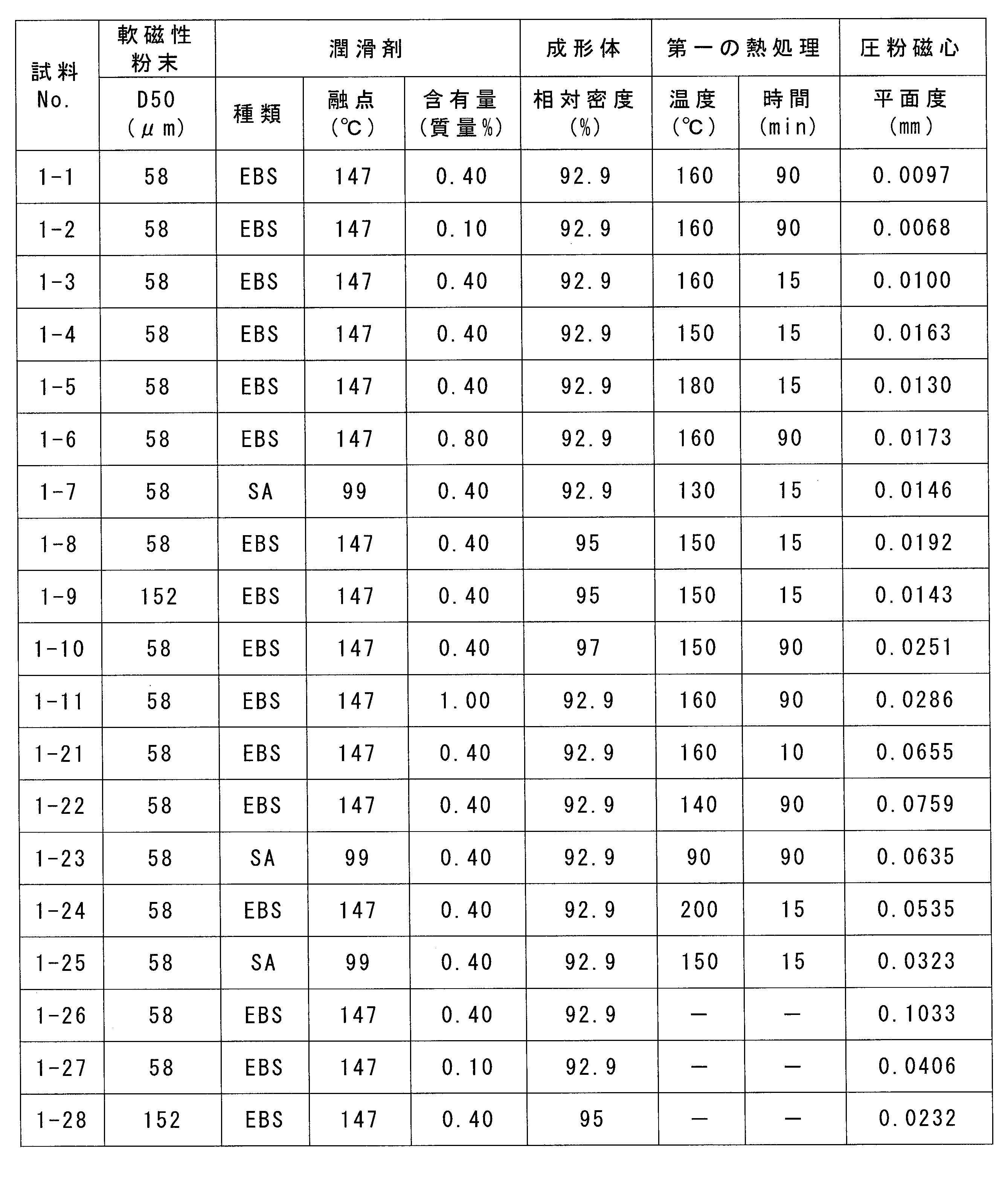
表1の結果から、成形体に潤滑剤の融点Tm以上(Tm+50℃)以下の温度域で10分超の第一の熱処理を施してから歪を除去可能な温度で熱処理した試料No.1-1~1-11の圧粉磁心は、平面度が0.03mm以下であり、平面度に優れることがわかる。これは、成形体に特定の温度かつ時間の第一の熱処理を施すことで、潤滑剤が融解され、この融解した潤滑剤が軟磁性粒子間を伝って成形体の外部に除去されたことで、成形体の内部から外部に通じる空気の流路が確保されたからと考えられる。空気の流路が形成されると、その流路によって成形体に内包される空気が外部に除去される。そのため、歪が除去可能な温度域で成形体(第一熱処理体)を加熱した際でも、空気の急激な膨張が抑制され、成形体の表面が隆起することを抑制できたと考えられる。
特に、成形体に含まれる潤滑剤の含有量が1.0質量%未満で、かつ成形体の相対密度が97%未満である試料No.1-1~1-9の圧粉磁心は、平面度が0.02mm以下であり、更に平面度に優れることがわかる。これは、潤滑剤の含有量が少ないことで、第一の熱処理によって潤滑剤を成形体の外部に除去し易いからと考えられる。また、成形体の相対密度が小さいことで、潤滑剤が成形体の外部に除去された状態で、軟磁性粒子間に隙間が形成され易く、成形体の外部に空気を除去し易いからと考えられる。成形体に含まれる潤滑剤の含有量が比較的少なく、かつ第一の熱処理時間が長い試料No.1-1,1-2の圧粉磁心は、平面度が0.01mm以下と非常に平面度に優れることがわかる。これは、第一の熱処理によって成形体に含まれる潤滑剤の大部分が成形体の外部に除去されたことで、成形体の内部に潤滑剤が実質的に残存しない状態とできたことによると考えられる。
一方、第一の熱処理を施さずに歪を除去可能な高い温度で熱処理した試料No.1-26~1-28の圧粉磁心は、平面度に劣ることがわかる。これは、第一の熱処理を行っておらず、成形体に空気が内包された状態で歪を除去可能な高い温度で熱処理したため、成形体に内包された空気が急激に膨張したからと考えられる。なお、試料No.1-28の圧粉磁心は、第一の熱処理を行っていない他の試料No.1-26,1-27と比較して平面度に優れることがわかる。これは、成形体に含まれる軟磁性粉末の平均粒径が比較的大きいため、試料No.1-26,1-27に比較して成形体の強度が高くなり、成形体に内包される空気が膨張した際の内圧に耐えることができたからと考えられる。
また、第一の熱処理の熱処理温度が低い試料No.1-22,1-23の圧粉磁心、及び熱処理時間が短い試料No.1-21の圧粉磁心は、平面度に劣ることがわかる。これは、第一の熱処理によって潤滑剤が十分に成形体の外部に除去できず、成形体の内部に潤滑剤が多く残存したからと考えられる。一方、第一の熱処理の熱処理温度が高い試料No.1-24,1-25の圧粉磁心も、平面度に劣ることがわかる。これは、潤滑剤を成形体の外部に除去する過程で、第一の熱処理の熱処理温度によって成形体に内包される空気が膨張したからと考えられる。
Claims (8)
- 原料粉末を加圧成形して成形体とする工程と、
前記成形体に第一の熱処理を施して第一熱処理体とする工程と、
前記第一熱処理体に第二の熱処理を施して第二熱処理体とする工程とを備え、
前記原料粉末は、軟磁性粉末と、融点がTmである潤滑剤とを含み、
前記第一の熱処理は、Tm以上(Tm+50℃)以下の温度域で10分超行い、
前記第二の熱処理は、前記第一の熱処理における温度域よりも高く、かつ400℃以上900℃以下の温度域で3分以上90分以下行う、
圧粉磁心の製造方法。 - 前記軟磁性粉末の平均粒径D50が220μm以下である請求項1に記載の圧粉磁心の製造方法。
- 前記潤滑剤の融点Tmが80℃以上230℃以下である請求項1又は請求項2に記載の圧粉磁心の製造方法。
- 前記原料粉末に占める前記潤滑剤の含有量が0.1質量%以上1.0質量%未満である請求項1から請求項3のいずれか1項に記載の圧粉磁心の製造方法。
- 前記成形体の相対密度を97%未満とする請求項1から請求項4のいずれか1項に記載の圧粉磁心の製造方法。
- 前記第一の熱処理は、非酸化性雰囲気で行う請求項1から請求項5のいずれか1項に記載の圧粉磁心の製造方法。
- 前記加圧成形は、成形金型を(Tm-100℃)以上(Tm-20℃)以下の温度に加熱した状態で行う請求項1から請求項6のいずれか1項に記載の圧粉磁心の製造方法。
- 原料粉末を加圧成形して成形体とする工程と、
前記成形体に第一の熱処理を施して第一熱処理体とする工程と、
前記第一熱処理体に第二の熱処理を施して第二熱処理体とする工程とを備え、
前記原料粉末は、軟磁性粉末と、融点Tmが80℃以上230℃以下である潤滑剤とを含み、
前記軟磁性粉末の平均粒径D50が220μm以下であり、
前記第一の熱処理は、Tm以上(Tm+50℃)以下の温度域で10分超行い、
前記第二の熱処理は、前記第一の熱処理における温度域よりも高く、かつ400℃以上900℃以下の温度域で3分以上90分以下行う、
圧粉磁心の製造方法。
Priority Applications (4)
| Application Number | Priority Date | Filing Date | Title |
|---|---|---|---|
| DE112019003356.5T DE112019003356T5 (de) | 2018-07-04 | 2019-06-18 | Verfahren zur herstellung eines pulvermagnetkerns |
| US17/256,759 US11636963B2 (en) | 2018-07-04 | 2019-06-18 | Method for manufacturing powder magnetic core |
| JP2020528774A JP7124081B2 (ja) | 2018-07-04 | 2019-06-18 | 圧粉磁心の製造方法 |
| CN201980044300.0A CN112437965B (zh) | 2018-07-04 | 2019-06-18 | 压粉铁心的制造方法 |
Applications Claiming Priority (2)
| Application Number | Priority Date | Filing Date | Title |
|---|---|---|---|
| JP2018127889 | 2018-07-04 | ||
| JP2018-127889 | 2018-07-04 |
Publications (1)
| Publication Number | Publication Date |
|---|---|
| WO2020008866A1 true WO2020008866A1 (ja) | 2020-01-09 |
Family
ID=69060317
Family Applications (1)
| Application Number | Title | Priority Date | Filing Date |
|---|---|---|---|
| PCT/JP2019/024139 Ceased WO2020008866A1 (ja) | 2018-07-04 | 2019-06-18 | 圧粉磁心の製造方法 |
Country Status (5)
| Country | Link |
|---|---|
| US (1) | US11636963B2 (ja) |
| JP (1) | JP7124081B2 (ja) |
| CN (1) | CN112437965B (ja) |
| DE (1) | DE112019003356T5 (ja) |
| WO (1) | WO2020008866A1 (ja) |
Citations (5)
| Publication number | Priority date | Publication date | Assignee | Title |
|---|---|---|---|---|
| JP2012186255A (ja) * | 2011-03-04 | 2012-09-27 | Sumitomo Electric Ind Ltd | 圧粉磁心とその製造方法 |
| JP2013098384A (ja) * | 2011-11-01 | 2013-05-20 | Sumitomo Electric Ind Ltd | 圧粉磁心 |
| WO2013154146A1 (ja) * | 2012-04-12 | 2013-10-17 | アイダエンジニアリング株式会社 | 混合粉末の高密度成形方法および高密度成形装置 |
| WO2013161747A1 (ja) * | 2012-04-23 | 2013-10-31 | アイダエンジニアリング株式会社 | 混合粉末の高密度成形方法、高密度成形装置および高密度3層構造圧粉体 |
| WO2016158336A1 (ja) * | 2015-03-27 | 2016-10-06 | 住友電工焼結合金株式会社 | 成形体の熱処理方法、および圧粉磁心 |
Family Cites Families (8)
| Publication number | Priority date | Publication date | Assignee | Title |
|---|---|---|---|---|
| JPS57188601A (en) * | 1981-05-18 | 1982-11-19 | Hitachi Powdered Metals Co Ltd | Strengthening method for green compact in powder metallurgy |
| JP5417074B2 (ja) * | 2009-07-23 | 2014-02-12 | 日立粉末冶金株式会社 | 圧粉磁心及びその製造方法 |
| JP2011176991A (ja) * | 2010-02-25 | 2011-09-08 | Tdk Corp | ローターコア及び電動機 |
| WO2012077750A1 (ja) * | 2010-12-08 | 2012-06-14 | アイダエンジニアリング株式会社 | 高強度焼結成形体の製造方法およびその製造装置 |
| TW201417911A (zh) * | 2012-04-12 | 2014-05-16 | Aida Eng Ltd | 混合粉末之高密度成形方法及高密度成形裝置 |
| EP2842665A4 (en) * | 2012-04-23 | 2016-03-09 | Aida Eng Ltd | HIGH DENSITY MOLDING DEVICE AND METHOD FOR HIGH DENSITY MOLDING OF MIXED POWDER |
| JP2016207711A (ja) * | 2015-04-16 | 2016-12-08 | 株式会社ジェイテクト | 磁石の製造方法及び磁石 |
| JP6926421B2 (ja) * | 2016-09-08 | 2021-08-25 | スミダコーポレーション株式会社 | 複合磁性材料、その複合磁性材料を熱硬化して得られる複合磁性成形体、その複合磁性成形体を用いて得られる電子部品、およびそれらの製造方法 |
-
2019
- 2019-06-18 DE DE112019003356.5T patent/DE112019003356T5/de active Pending
- 2019-06-18 WO PCT/JP2019/024139 patent/WO2020008866A1/ja not_active Ceased
- 2019-06-18 JP JP2020528774A patent/JP7124081B2/ja active Active
- 2019-06-18 CN CN201980044300.0A patent/CN112437965B/zh active Active
- 2019-06-18 US US17/256,759 patent/US11636963B2/en active Active
Patent Citations (5)
| Publication number | Priority date | Publication date | Assignee | Title |
|---|---|---|---|---|
| JP2012186255A (ja) * | 2011-03-04 | 2012-09-27 | Sumitomo Electric Ind Ltd | 圧粉磁心とその製造方法 |
| JP2013098384A (ja) * | 2011-11-01 | 2013-05-20 | Sumitomo Electric Ind Ltd | 圧粉磁心 |
| WO2013154146A1 (ja) * | 2012-04-12 | 2013-10-17 | アイダエンジニアリング株式会社 | 混合粉末の高密度成形方法および高密度成形装置 |
| WO2013161747A1 (ja) * | 2012-04-23 | 2013-10-31 | アイダエンジニアリング株式会社 | 混合粉末の高密度成形方法、高密度成形装置および高密度3層構造圧粉体 |
| WO2016158336A1 (ja) * | 2015-03-27 | 2016-10-06 | 住友電工焼結合金株式会社 | 成形体の熱処理方法、および圧粉磁心 |
Also Published As
| Publication number | Publication date |
|---|---|
| JPWO2020008866A1 (ja) | 2021-08-02 |
| US11636963B2 (en) | 2023-04-25 |
| JP7124081B2 (ja) | 2022-08-23 |
| US20210249167A1 (en) | 2021-08-12 |
| DE112019003356T5 (de) | 2021-03-18 |
| CN112437965A (zh) | 2021-03-02 |
| CN112437965B (zh) | 2022-07-22 |
Similar Documents
| Publication | Publication Date | Title |
|---|---|---|
| CN102202818B (zh) | 压粉磁芯及其制造方法 | |
| CA2613862C (en) | Method for manufacturing of insulated soft magnetic metal powder formed body | |
| JP5050745B2 (ja) | リアクトル用コアとその製造方法およびリアクトル | |
| US20130277601A1 (en) | Composite, soft-magnetic powder and its production method, and dust core formed thereby | |
| JP6511832B2 (ja) | 軟磁性金属粉末、およびその粉末を用いた軟磁性金属圧粉コア | |
| WO2008093430A1 (ja) | 高圧縮性鉄粉、およびそれを用いた圧粉磁芯用鉄粉と圧粉磁芯 | |
| JP6511831B2 (ja) | 軟磁性金属粉末、およびその粉末を用いた軟磁性金属圧粉コア | |
| WO2011010561A1 (ja) | 圧粉磁心及びその製造方法 | |
| JP2008172257A (ja) | 絶縁軟磁性金属粉末成形体の製造方法 | |
| JP2008297606A (ja) | 圧粉磁心用金属粉末および圧粉磁心の製造方法 | |
| JP2013098384A (ja) | 圧粉磁心 | |
| JP7247670B2 (ja) | R-t-b系永久磁石およびその製造方法 | |
| CN111210987A (zh) | 一种r-t-b磁体材料及其制备方法和应用 | |
| TWI478184B (zh) | 壓粉磁心用混合粉末、壓粉磁心及壓粉磁心之製造方法 | |
| JP2019178402A (ja) | 軟磁性粉末 | |
| WO2015151486A1 (ja) | 圧粉磁芯用鉄粉および圧粉磁芯用鉄粉の選別方法 | |
| CA2891206C (en) | Iron powder for dust cores | |
| JP2007092162A (ja) | 高圧縮性鉄粉、およびそれを用いた圧粉磁芯用鉄粉と圧粉磁芯 | |
| KR20190056314A (ko) | 연자성 금속 분말 및 그 제조 방법 및 연자성 금속 압분 코어 | |
| WO2020008866A1 (ja) | 圧粉磁心の製造方法 | |
| JP6073066B2 (ja) | 圧粉磁心用軟磁性鉄基粉末の製造方法 | |
| JP5682725B1 (ja) | 軟磁性金属粉末および軟磁性金属圧粉コア | |
| US11794244B2 (en) | Method for manufacturing dust core and raw material powder for dust core | |
| WO2016076154A1 (ja) | 磁石用成形体、磁性部材、磁石用成形体の製造方法、及び磁性部材の製造方法 | |
| JP2025006199A (ja) | 圧粉磁心の製造方法 |
Legal Events
| Date | Code | Title | Description |
|---|---|---|---|
| 121 | Ep: the epo has been informed by wipo that ep was designated in this application |
Ref document number: 19830296 Country of ref document: EP Kind code of ref document: A1 |
|
| ENP | Entry into the national phase |
Ref document number: 2020528774 Country of ref document: JP Kind code of ref document: A |
|
| 122 | Ep: pct application non-entry in european phase |
Ref document number: 19830296 Country of ref document: EP Kind code of ref document: A1 |