WO2020008640A1 - 遮断器 - Google Patents
遮断器 Download PDFInfo
- Publication number
- WO2020008640A1 WO2020008640A1 PCT/JP2018/025766 JP2018025766W WO2020008640A1 WO 2020008640 A1 WO2020008640 A1 WO 2020008640A1 JP 2018025766 W JP2018025766 W JP 2018025766W WO 2020008640 A1 WO2020008640 A1 WO 2020008640A1
- Authority
- WO
- WIPO (PCT)
- Prior art keywords
- slider
- circuit breaker
- actuator
- attached
- slit
- Prior art date
Links
Images


Classifications
-
- H—ELECTRICITY
- H01—ELECTRIC ELEMENTS
- H01H—ELECTRIC SWITCHES; RELAYS; SELECTORS; EMERGENCY PROTECTIVE DEVICES
- H01H71/00—Details of the protective switches or relays covered by groups H01H73/00 - H01H83/00
- H01H71/04—Means for indicating condition of the switching device
Definitions
- the present invention relates to a switch attached to a circuit breaker for opening and closing an electric circuit.
- Some circuit breakers have an attached switch that outputs a contact signal indicating whether the circuit breaker body is on or off.
- the attached switch is rotatably supported, and has an actuator that rotates at the time of a closing operation in which the circuit breaker main body shifts from the off state to the on state.
- the attached switch changes the state between the internal contacts as the actuator rotates.
- the main shaft of the opening / closing mechanism rotates during the closing operation of the circuit breaker body beyond the ON position of the circuit breaker body in order to ensure reliable contact between the contacts forming the electric circuit.
- the circuit breaker described in Patent Document 1 has a configuration in which the rotational force of the actuator beyond the operating position is absorbed by a leaf spring.
- the present invention has been made in view of the above, and an object of the present invention is to provide a circuit breaker that can suppress an increase in a force required when the circuit breaker body is closed.
- a circuit breaker of the present invention includes a circuit breaker body that opens and closes an electric circuit, an attached switch, a mounting portion, a slider, a rotating plate, and a tension spring.
- the attached switch has an actuator rotatably supported, and the state of the internal contacts changes according to the rotation of the actuator.
- An attachment switch is attached to the attachment portion, and a slit extending in a direction toward the actuator is formed.
- the slider has a protrusion inserted into the slit, and rotates along with the actuator by moving along the slit and pressing the actuator.
- the rotating plate rotates with the closing operation of the circuit breaker body and pushes the slider.
- the tension spring is bridged between the slider and the mounting portion and urges the slider in a direction to separate the slider from the actuator.
- the slider is pushed by the rotating plate that rotates with the throwing operation, moves along the slit, and the protrusion moves to the end of the slit, and is further pushed by the rotating plate to rotate.
- FIG. 1 is an external perspective view of a circuit breaker according to Embodiment 1 of the present invention.
- FIG. 2 is an external perspective view of the circuit breaker with the attached cover removed according to the first embodiment.
- FIG. 4 is a diagram for explaining a configuration of an attached switch according to the first embodiment;
- FIG. 2 is a perspective view showing a part of an internal mechanism of the circuit breaker according to the first embodiment in an off state.
- FIG. 2 is a perspective view showing a part of an internal mechanism of the circuit breaker according to the first embodiment in an ON state.
- FIG. 2 is an external perspective view of a slider according to the first embodiment.
- FIG. 4 is a diagram illustrating a state where a slider is arranged on a fixed base that forms the attachment portion according to the first embodiment; The figure which shows a mode that the attachment frame part which comprises an attachment part is attached to the fixed base in the state which arrange
- FIG. 3 is a plan view of the mounting portion according to the first embodiment with the slider removed. Sectional view along the line XI-XI in FIG. Enlarged view of the slit shown in FIG. FIG.
- FIG. 7 is a diagram for explaining states of an attached switch, a rotating plate, and a slider when the circuit breaker body according to the first embodiment is in an off state.
- FIG. 7 is a diagram for explaining states of an attached switch, a rotating plate, and a slider when the circuit breaker body according to the first embodiment is in an off state.
- FIG. 6 is a diagram for explaining states of an attached switch, a rotating plate, and a slider when the circuit breaker body according to the first embodiment is in a transition state from an off state to an on state.
- FIG. 6 is a diagram for explaining states of an attached switch, a rotating plate, and a slider when the circuit breaker body according to the first embodiment is in a transition state from an off state to an on state.
- FIG. 4 is a diagram for explaining states of a rotating plate and a slider when the circuit breaker body according to the first embodiment is in an on state.
- FIG. 4 is a diagram for explaining a force applied to the slider according to the first embodiment.
- FIG. 7 is a diagram for explaining a relationship between a slider and a rotating plate in the circuit breaker according to the second embodiment of the present invention.
- FIG. 7 is a view for explaining a method of fixing the attached switch according to the second embodiment.
- the circuit breaker according to the first embodiment is a circuit breaker that opens and closes an electric circuit such as an air circuit breaker, and detects at least one of an overcurrent and a leakage current to interrupt the electric circuit.
- the Z-axis positive direction is set to the upper side
- the Z-axis negative direction is set to the lower side
- the X-axis positive direction is set to the right
- the X-axis negative direction is set to the left
- the Y-axis positive direction is set to the front
- the Y-axis negative direction is the rear.
- clockwise and counterclockwise mean clockwise and counterclockwise in the drawings described later.
- the front, rear, up, down, left, and right directions are directions in a state where the circuit breaker is assembled.
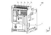
- FIG. 1 is an external perspective view of the circuit breaker according to the first embodiment of the present invention
- FIG. 2 is an external perspective view of the circuit breaker with the attached cover according to the first embodiment removed.
- the circuit breaker 100 according to the first embodiment includes a circuit breaker main body 1 that opens and closes an electric circuit (not shown) and an attached cover 2.
- the circuit breaker 100 includes a circuit breaker more accessory switch 3 1 is removably attached to the upper portion of the main body 1, 3 2, 3 3, 3 4, 3 5. More accessory switch 3 1, 3 2, 3 3, 3 4, 3 5 are configured as separate members. Accessory cover 2, for example, when they are detached from the accessory switch 3 1, 3 2, 3 3, 3 4, 3 5 breaker or breaker body 1 when attached to the body 1, is removed.
- a plurality of accessory switches 3 1, 3 2, 3 3, 3 4, 3 5 if shown without each distinguished to as accessory switch 3.
- the attached switch 3 outputs to the outside whether the circuit breaker main body 1 is in the ON state or the OFF state by a contact output.
- the circuit breaker main body 1 When the circuit breaker main body 1 is in the ON state, the electric circuit is in the closed state.
- the circuit breaker body 1 is in the off state, the electric circuit is in the open state.
- the closing operation of the circuit breaker body 1 changes the circuit breaker body 1 from the off state to the on state.
- FIG. 3 is a diagram for explaining the configuration of the attached switch according to the first embodiment.
- the accessory switch 3 according to the first embodiment includes micro switches 31 and 32, an actuator 33, leaf springs 34 and 35, and a case 36.
- the case 36 has a recess 361 that is recessed rightward.
- the microswitches 31 and 32, a part of the actuator 33, and the leaf springs 34 and 35 are arranged in the case 36 of the attached switch 3.
- the case 36 has a common configuration among the plurality of accessory switches 3, and can accommodate micro switches 31 and 32 having different sizes among the plurality of accessory switches 3.
- each accessory switch 3 is configured as a cassette by a single type of case. In FIG. 3 and the like, the entire portion of the actuator 33 including the portion arranged in the case 36 is indicated by a solid line.
- the microswitch 31 has a movable protrusion 311 that can move in the vertical direction.
- the state of the microswitch 31 between the internal contacts changes.
- the contact points inside the microswitch 31 change from a non-contact state to a contact state.
- the micro switch 31 electrically outputs that the circuit breaker main body 1 is in the ON state.
- the microswitch 32 has a movable projection 321 that can move in the vertical direction.
- the state of the microswitch 32 changes between the internal contacts.
- the micro switch 32 outputs a contact signal indicating that the circuit breaker main body 1 is in the ON state.
- one or both of the microswitches 31 and 32 may have a configuration in which when the movable projections 311 and 321 are pressed, the internal contacts change from a contact state to a non-contact state.
- the actuator 33 includes a shaft portion 331 rotatably supported by the case 36 of the attached switch 3, a first extending portion 332 having a central portion fixed to the shaft portion 331 and extending in the front-rear direction, and a base end portion 333a. And a second extending portion 333 which is fixed to the one end portion 332 a side of the first extending portion 332 and extends in a direction orthogonal to the extending direction of the first extending portion 332.
- the actuator 33 is formed of an insulating member such as a resin.
- the leaf spring 34 is disposed between the first extension portion 332 of the actuator 33 and the movable protrusion 311 of the micro switch 31.
- the leaf spring 34 has the front end 342 attached to the one end 332a. Pressed. Thereby, the tip 342 of the leaf spring 34 moves toward the microswitch 31, and the center 343 of the leaf spring 34 pushes the movable projection 311.
- the leaf spring 35 is disposed between the first extension 332 of the actuator 33 and the movable protrusion 321 of the micro switch 32.
- the leaf spring 35 has the front end 352 at the other end. 332b.
- the tip 352 of the leaf spring 35 moves toward the microswitch 32, and the center 353 of the leaf spring 35 pushes the movable projection 321.
- the attached switch 3 has a configuration in which the plate springs 34 and 35 are provided, but may have a configuration in which the plate springs 34 and 35 are not provided.
- the movable protrusions 311 and 321 of the attached switch 3 are arranged, for example, at positions where the movable protrusions 311 and 321 are directly pressed by the first extension portion 332 of the actuator 33.
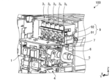
- FIG. 4 is a perspective view showing a part of the internal mechanism of the circuit breaker according to the first embodiment in an off state
- FIG. 5 is a diagram showing a part of the internal mechanism of the circuit breaker according to the first embodiment in an on state.
- the circuit breaker main body 1 of the circuit breaker 100 is in a state in which a current-carrying part (not shown) including a movable contact and a fixed contact is in contact with the movable contact and the fixed contact. And an opening / closing mechanism section 4 for switching between a separated state and a separated state.
- the opening and closing mechanism 4 includes a main shaft 5.
- the opening / closing mechanism unit 4 When the closing operation of the circuit breaker main body 1 is performed, the opening / closing mechanism unit 4 generates a driving force for rotating the main shaft 5 in the direction of arrow A shown in FIG.
- the main shaft 5 is rotated in the direction of arrow A by such a driving force, the movable contact and the fixed contact are brought into contact with each other at an energized portion (not shown) of the circuit breaker main body 1, and the circuit breaker main body 1 is turned on.
- an electric circuit (not shown) is closed.
- the circuit breaker 100 includes a rotating plate 6 fixed to the main shaft 5, a slider 7 moved by the rotating plate 6, and a mounting portion 9 arranged on an upper portion of the circuit breaker main body 1. Included with the mounting portion 9 switches 3 1, 3 2, 3 3, 3 4, 3 5 is detachably attached. Further, as shown in FIG. 5, the mounting portion 9 includes a fixed base 91 and a mounting frame portion 92, and holds the slider 7 slidably.
- FIG. 6 is an external perspective view of the slider according to the first embodiment.
- the slider 7 according to the first embodiment includes a slider body 71 extending in the left-right direction, and a pair of left and right levers 72 disposed below the slider body 71 and pressed by the rotating plate 6. .
- the slider main body 71 has a pair of left and right cylindrical protrusions 711 slidably inserted into slits 93 described later formed in the mounting portion 9 in a long hole shape, and a contact portion contacting the actuator 33 of the attached switch 3. 712.
- the outer peripheral surfaces of the pair of projections 711 have the same central axis.
- the contact portion 712 has an arcuate surface centered on the central axis of the protrusion 711, and the arcuate surface contacts the actuator 33.
- the lever 72 has a main body 721 that is continuous with the lower end of the slider main body 71, and a protruding piece 722 that protrudes leftward or rightward from the main body 721.
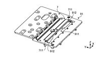
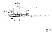
- FIG. 7 is a diagram illustrating a state in which the slider is arranged on the fixed base that forms the attachment unit according to the first embodiment.
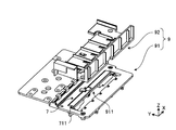
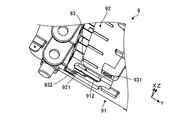
- FIG. 8 is a diagram illustrating a state in which the mounting frame portion that forms the mounting portion is mounted on the fixed base on which the slider according to the first embodiment is arranged.
- FIG. 9 is a diagram illustrating a state where the mounting frame portion is mounted on the fixed base in a state where the slider according to the first embodiment is arranged.
- the slider 7 is arranged on a fixed base 91 constituting the mounting portion 9 shown in FIG. Specifically, the fixed base 91 has an opening 911. After the slider 7 is inserted into the opening 911 of the fixed base 91 from below and then moved forward, it is arranged on the fixed base 91 as shown in FIG. In the state shown in FIG. 7, the protrusion 711 of the slider 7 is placed in a groove 912 formed in the fixed base 91.
- FIG. 10 is a plan view of the mounting portion with the slider according to the first embodiment removed
- FIG. 11 is a cross-sectional view taken along line XI-XI of FIG.
- FIG. 12 is an enlarged view of the slit shown in FIG.
- the mounting frame 92 has a groove 921 formed therein.
- the slit 93 into which the protrusion 711 is inserted is formed by the groove 912 of the fixed base 91 and the groove 921 of the mounting frame 92.
- the protrusion 711 of the slider 7 moves in the slit 93, the slider 7 can slide in the front-back direction.
- the protrusion 711 is movable in a range R from a front end 931 to a rear end 932. Since the slit 93 is formed by the groove portion 912 and the groove portion 921, the mounting portion 9 is configured to be easily assembled.
- FIGS. 13 and FIG. 14 are diagrams for explaining states of the attached switch, the rotating plate, and the slider when the circuit breaker body according to the first embodiment is in an off state.
- FIGS. 15 and 16 are diagrams for explaining the states of the attached switches, the rotating plate, and the slider when the circuit breaker body according to the first embodiment is in the transition state from the off state to the on state.
- FIGS. 17 and 18 are diagrams for explaining an overrun state by the rotating plate after the circuit breaker body according to the first embodiment has been turned on from the off state.
- FIG. 19 is a diagram for explaining states of the rotating plate and the slider when the circuit breaker body according to the first embodiment is in an ON state.
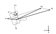
- FIG. 20 is a diagram for explaining a force applied to the slider according to the first embodiment.
- the protrusions 711 provided on both left and right ends of the slider body 71 are held by the surface of the mounting portion 9 forming the slit 93 so as to be movable in the front-rear direction.
- the slit 93 extends in a direction toward the actuator 33.
- the tension spring 8 is bridged between the slider 7 and the mounting portion 9 and urges the slider 7 in a direction separating from the actuator 33.
- FIGS. 13 and 14 when the circuit breaker main body 1 is in the off state, the lever 72 of the slider 7 is pulled forward by the extension spring 8.
- the left and right protrusions 711 of the slider body 71 are in contact with the front end 931 of the slit 93.
- the protrusion 711 of the slider body 71 is arranged in the slit 93 so as to be movable in the front-rear direction. Therefore, when the lever 72 is pushed backward by the protrusion 61 of the rotating plate 6, the state shown in FIG. 13 shifts to the state shown in FIG. 15, and the protrusion 711 moves rearward along the slit 93.
- the actuator 33 When the slider main body 71 is in the position where the backward movement is restricted, the breaker main body 1 is in the ON state, and the actuator 33 operates the movable projections of the micro switches 31 and 32 via the leaf springs 34 and 35. It is in a state where 311 and 321 are pushed. That is, when the slider main body 71 is at the position where the backward movement is regulated, the actuator 33 of the microswitches 31 and 32 is at the operating position where the state between the internal contacts changes. Therefore, the microswitches 31 and 32 output a contact output indicating that the circuit breaker body 1 is in the ON state.
- the rotating plate 6 temporarily rotates clockwise further than the ON position, which is the ON position of the circuit breaker main body 1, as shown in FIGS. After the contact operation between the movable contact and the fixed contact at the conducting portion (not shown) of the circuit breaker body 1 is completed, the circuit breaker rotates counterclockwise to the ON position shown in FIG. Is completed.
- the circuit breaker 100 restricts the rearward movement of the protrusion 711 by the surface forming the end 932 of the slit 93 at the position where the circuit breaker main body 1 is in the ON state.
- a configuration is provided in which the projection 711 is rotatably held by the surface forming the end 932 of the slit 93.
- the pull spring is attached to the lever 72 of the slider 7 being pressed by the protrusion 61 of the rotary plate 6.
- the force F3 which is a combination of the tension F1 of FIG. 8 and the driving force F2 of the rotating plate 6, acts on the lever 72. Since the force F3 takes a line of force so as to rotate the slider 7 in the direction indicated by the arrow E around the protrusion 711, the slider 7 rotates in the direction indicated by the arrow E.
- the tension spring 8 is bridged between the mounting portion 9 and the slider 7 so that the line of force is inclined upward in the front-rear direction, which is the direction in which the slider 7 moves along the slit 93, the slider 7 Can be suppressed. Therefore, when vibration or the like is applied to the circuit breaker 100, abnormal noise and chattering can be suppressed.
- the contact portion 712 of the slider 7 where the slider 7 contacts the actuator 33 has an arc-shaped surface. Therefore, when the slider 7 in which the protrusion 711 reaches the end 932 of the slit 93 rotates, it is possible to prevent the actuator 33 from rotating, and to prevent an excessive force from acting on the actuator 33. . This prevents an excessive driving force from being applied to the microswitches 31 and 32 and the actuator 33 as compared with, for example, a case where the second extension 333 of the actuator 33 is directly pushed by the protrusion 61 of the rotating plate 6. Can be.
- the circuit breaker 100 includes the circuit breaker main body 1 that opens and closes an electric circuit, and the actuator 33 that is rotatably supported. And an attachment portion 9 to which the accessory switch 3 is attached and in which a slit 93 extending in a direction toward the actuator 33 is formed. Further, the circuit breaker 100 has a projection 711 inserted into the slit 93, and the slider 7 that moves along the slit 93 to rotate the actuator 33 by pressing the actuator 33, and the closing operation of the circuit breaker body 1.
- the actuator 33 exceeds the operating position where the internal contact state of the attached switch 3 changes, it is possible to suppress the application of the force for rotating the actuator 33, and thereby, it is necessary to perform the closing operation of the circuit breaker body 1. An increase in force can be suppressed. Further, it is possible to prevent an excessive driving force from being applied to the micro switches 31, 32 and the actuator 33.
- the slider 7 includes a slider body 71 having a protrusion 711 inserted into the slit 93, a contact portion 712 having a surface in contact with the actuator 33 formed in an arc shape, and a rotation in the rotation direction of the rotating plate 6.
- a lever 72 protruding from the slider body 71 at a position facing the plate 6 and pushed by the rotating plate 6 is provided.
- the slider 7 is formed of an insulating member such as a resin. As a result, insulation between the current-carrying part (not shown) of the circuit breaker main body 1 can be ensured.
- Embodiment 2 FIG.
- the circuit breaker according to the second embodiment is different from the first embodiment in that the mounting position of the rotary plate to the main shaft is provided below the attached switch and a lock member is provided.
- components having functions similar to those of the first embodiment are denoted by the same reference numerals, and description thereof will be omitted. The following description focuses on differences from circuit breaker 100 of the first embodiment.
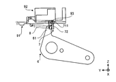
- FIG. 21 is a diagram for explaining the relationship between the slider and the rotating plate in the circuit breaker according to the second embodiment of the present invention. As shown in FIG. 21, in the circuit breaker 100A according to the second embodiment, a plurality of rotating plates 6 are attached to the main shaft 5.
- the rotary plate 6 is located below the attached switch 3 and acts on the main body 721 of the lever 72 of the slider 7 located below the attached switch 3. Therefore, the circuit breaker 100A can drive the actuators 33 of the attached switches 3 simultaneously and stably simultaneously, as compared with the case where the rotating plate 6 acts on the protruding piece 722 of the lever 72, and mounts the attached switches 3 side by side. Reliability can be improved at the time of driving.
- the reliability when the plurality of attached switches 3 are arranged and driven is further improved. Can be done.
- the protrusion 72 is provided on the lever 72 of the slider 7. However, a configuration in which the protrusion 722 is not provided may be employed.
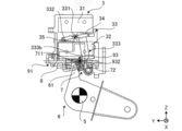
- FIG. 22 is a diagram for explaining a method for fixing the attached switch according to the second embodiment.
- the circuit breaker 100A according to the second embodiment a plurality of accessory switches 3 1, 3 2, 3 3, 3 4, 3 5 the locking member 40 for fixing the same time the mounting portion 9 Have.
- Locking member 40 includes a slide portion 41, a plurality of projections 42 1, 42 2, 42 3, 42 4, 42 5, and an operation unit 43.
- Slide portion 41 has a plurality of accessory switches 3 1, 3 2, 3 3, 3 4, 3 extending along the direction of arrangement of 5, slide grooves 913 formed in the fixed base 91 of the mounting portion 9.
- a plurality of protrusions 42 1, 42 2, 42 3, 42 4, 42 5 are arranged at intervals along the extending direction of the slide portion 41, a plurality of accessory switches from the slide portion 41 3 1, 3 2, 3 3, respectively projecting toward the 3 4, 3 5.
- the operation section 43 extends upward from an end of the slide section 41.
- the slide unit 41 slides along the groove 913 formed on the fixed base 91, and the plurality of protrusions 42 1 , 42 2 , 42 3 , and 42 4 are provided.
- 42 5 are inserted into a plurality of accessory switches 3 1, 3 2, 3 3, 3 4, 3 recess 361 recessed in the direction indicated by 5 in the form and arrow F.
- the movement of the plurality of attached switches 3 1 , 3 2 , 3 3 , 3 4 , 3 5 is regulated, and the plurality of attached switches 3 1 , 3 2 , 3 3 , 3 4 , 3 5 are attached to the mounting portion 9.
- the plurality of attached switches 3 are configured separately from each other, it is possible to easily replace only a part of the plurality of attached switches 3. Therefore, in the circuit breaker 100A, the replacement of the accessory switch 3 is facilitated as compared with a case where a plurality of accessory switches are stacked to form one unit.
- each of the plurality of attached switches 3 has the concave portion 361 recessed in the direction in which the plurality of attached switches 3 are arranged.
- the mounting portion 9 slides in the mounting frame portion 92 to which the plurality of attached switches 3 are mounted, the groove 913 formed along the left-right direction that is the arrangement direction of the attached switches 3, and the plurality of attached switches 3.
- the third recess 361 and a locking member 40 having a plurality of projections 42 1, 42 2, 42 3, 42 4, 42 5 are respectively inserted.
- the plurality of rotating plates 6 are located below the attached switch 3, and press an area of the slider 7 located below the attached switch 3. Thereby, reliability can be improved when a plurality of attached switches 3 are arranged and mounted and driven.
- 1 breaker body 2 comes cover, 3,3 1, 3 2, 3 3, 3 4, 3 5 accessory switch, 4 closing mechanism, 5 the main shaft, 6 rotary plate, 7 a slider, 8 pull spring, 9 attached parts, 31 and 32 micro-switch, 33 an actuator, 34 and 35 the leaf spring, 36 cases, 40 locking member 41 slide portion, 42 1, 42 2, 42 3, 42 4, 42 5, 711 projections, 43 operation unit , 71 slider body, 72 lever, 91 fixing base, 92 mounting frame, 93 slit, 100, 100A circuit breaker, 311, 321 movable projection, 331 shaft, 332 first extension, 332a one end, 332b other end 333 second extension portion, 333a, 341, 351 base end portion, 333b, 342, 352 tip end portion, 343, 353 central portion, 361 concave portion, 7 Second contact portion, 721 main body, 722 projecting piece, 911 opening, 912,913,921 groove, 931 and 932 end.
Abstract
遮断器は、回転可能に支持されるアクチュエータ(33)を有し、アクチュエータ(33)の回転によって内部の接点間の状態が変化する付属スイッチ(3)と、付属スイッチ(3)が取り付けられ、アクチュエータ(33)へ向かう方向に延伸するスリット(93)が形成される取付部(9)と、スリット(93)に挿入される突起部(711)が形成され、スリット(93)に沿って移動してアクチュエータ(33)を押すことによってアクチュエータ(33)を回転させるスライダー(7)と、遮断器本体の投入動作に伴って回転してスライダーを押す回転板(6)と、を備える。スライダー(7)は、遮断器本体の投入動作に伴って回転する回転板(6)に押されてスリット(93)に沿って移動し突起部(711)がスリット(93)の端部まで移動した後、回転板(6)にさらに押されて回転する。
Description
本発明は、電路の開閉を行う遮断器の付属スイッチに関する。
遮断器には、遮断器本体がオン状態であるかオフ状態であるかを接点出力する付属スイッチを備えるものがある。付属スイッチは、回転可能に支持され、遮断器本体がオフ状態からオン状態へ移行する投入動作時に回転するアクチュエータを有する。付属スイッチは、アクチュエータの回転に伴って内部の接点間の状態が変化する。
遮断器本体は、電路を形成する接点同士の確実な接触を確保するため、遮断器本体の投入動作時において開閉機構部のメインシャフトが、遮断器本体のオン位置を超えて回転する。従来の遮断器では、メインシャフトがオン位置を超えて回転すると、付属スイッチにおいて内部の接点間の状態が変化する動作位置を超えてアクチュエータが回転する。そこで、特許文献1に記載の遮断器は、動作位置を超えたアクチュエータの回転力を板バネで吸収する構成を有している。
しかしながら、上述した従来の遮断器では、付属スイッチにおける接点間の状態が変化する動作位置を超えた回転力を板バネで吸収するため、遮断器本体の投入動作時に必要な力が増加する。上述した板バネの数は付属スイッチの設置数の増加に伴って増加することから、投入動作時に必要な力は付属スイッチの設置数の増加に伴って増加してしまう。
本発明は、上記に鑑みてなされたものであって、遮断器本体の投入動作時に必要な力の増加を抑制することができる遮断器を得ることを目的とする。
上述した課題を解決し、目的を達成するために、本発明の遮断器は、電路の開閉を行う遮断器本体と、付属スイッチと、取付部と、スライダーと、回転板と、引きバネとを備える。付属スイッチは、回転可能に支持されるアクチュエータを有し、アクチュエータの回転によって内部の接点間の状態が変化する。取付部は、付属スイッチが取り付けられ、アクチュエータへ向かう方向に延伸するスリットが形成される。スライダーは、スリットに挿入される突起部が形成され、スリットに沿って移動してアクチュエータを押すことによってアクチュエータを回転させる。回転板は、遮断器本体の投入動作に伴って回転してスライダーを押す。引きバネは、スライダーと取付部との間に架け渡され、スライダーをアクチュエータから引離す方向に付勢する。スライダーは、投入動作に伴って回転する回転板に押されてスリットに沿って移動し突起部がスリットの端部まで移動した後、回転板にさらに押されて回転する。
本発明によれば、遮断器本体の投入動作時に必要な力の増加を抑制することができる、という効果を奏する。
実施の形態1.
実施の形態1にかかる遮断器は、気中遮断器といった電路を開閉する遮断器であり、過電流および漏電流の少なくとも一方を検出して電路を遮断する。以下においては、説明の便宜上、Z軸正方向を上方とし、Z軸負方向を下方とし、X軸正方向を右方とし、X軸負方向を左方とし、Y軸正方向を前方とし、Y軸負方向を後方とする。また、以下において、時計回りおよび反時計回りとは、後述する図面上において時計回りおよび反時計回りであることを意味する。なお、遮断器の構成の一部のみを図示する場合において、前後、上下、および左右の各方向は、遮断器を組み立てた状態での方向である。
実施の形態1にかかる遮断器は、気中遮断器といった電路を開閉する遮断器であり、過電流および漏電流の少なくとも一方を検出して電路を遮断する。以下においては、説明の便宜上、Z軸正方向を上方とし、Z軸負方向を下方とし、X軸正方向を右方とし、X軸負方向を左方とし、Y軸正方向を前方とし、Y軸負方向を後方とする。また、以下において、時計回りおよび反時計回りとは、後述する図面上において時計回りおよび反時計回りであることを意味する。なお、遮断器の構成の一部のみを図示する場合において、前後、上下、および左右の各方向は、遮断器を組み立てた状態での方向である。
図1は、本発明の実施の形態1にかかる遮断器の外観斜視図であり、図2は、実施の形態1にかかる付属カバーを取り外した状態の遮断器の外観斜視図である。図1に示すように、実施の形態1にかかる遮断器100は、不図示の電路の開閉を行う遮断器本体1と、付属カバー2とを備える。
図2に示すように、遮断器100は、遮断器本体1の上部に着脱可能に取り付けられる複数の付属スイッチ31,32,33,34,35を有する。複数の付属スイッチ31,32,33,34,35は互いに別体として構成されている。付属カバー2は、例えば、付属スイッチ31,32,33,34,35が遮断器本体1に取り付けられる際または遮断器本体1から取り外される際に、取り外される。以下、複数の付属スイッチ31,32,33,34,35を各々区別せずに示す場合、付属スイッチ3と記載する。
付属スイッチ3は、遮断器本体1がオン状態であるかオフ状態であるかを接点出力によって外部に出力する。遮断器本体1がオン状態である場合、電路が閉状態である。遮断器本体1がオフ状態である場合、電路が開状態である。遮断器本体1の投入動作によって、遮断器本体1がオフ状態からオン状態になる。
図3は、実施の形態1にかかる付属スイッチの構成を説明するための図である。図3に示すように、実施の形態1にかかる付属スイッチ3は、マイクロスイッチ31,32と、アクチュエータ33と、板バネ34,35と、ケース36とを備える。ケース36には、右方向に凹んだ凹部361が形成される。
付属スイッチ3のケース36内には、マイクロスイッチ31,32、アクチュエータ33の一部、および板バネ34,35が配置されている。かかるケース36は、複数の付属スイッチ3間で共通の構成を有しており、複数の付属スイッチ3間で互いに大きさが異なるマイクロスイッチ31,32を収納することができる。このように、各付属スイッチ3は単一種類のケースによってカセット化されて構成されている。なお、図3などにおいては、アクチュエータ33のうちケース36内に配置される部分を含む全体を実線で示している。
マイクロスイッチ31は、上下方向に移動可能な可動突起311を有する。マイクロスイッチ31は、可動突起311が上方に押されると、内部の接点間の状態が変化する。例えば、可動突起311が押されると、マイクロスイッチ31の内部の接点間が非接触状態から接触状態に変化する。これにより、マイクロスイッチ31は、遮断器本体1がオン状態であることを電気的に接点出力する。
マイクロスイッチ32は、上下方向に移動可能な可動突起321を有する。マイクロスイッチ32は、可動突起321が下方に押されると、内部の接点間の状態が変化する。例えば、可動突起321が押されると、マイクロスイッチ32の内部の接点間が非接触状態から接触状態に変化する。これにより、マイクロスイッチ32は、遮断器本体1がオン状態であることを接点出力する。なお、マイクロスイッチ31,32のうち一方または両方は、可動突起311,321が押されると、内部の接点間が接触状態から非接触状態に変化する構成であってもよい。
アクチュエータ33は、付属スイッチ3のケース36に回転可能に支持された軸部331と、中央部が軸部331に固定され、前後方向に沿って延伸する第1延伸部332と、基端部333aが第1延伸部332の一端部332a側に固定され第1延伸部332の延伸方向と直交する方向に沿って延伸する第2延伸部333とを備える。かかるアクチュエータ33は、樹脂などの絶縁性部材によって形成される。
板バネ34は、アクチュエータ33における第1延伸部332とマイクロスイッチ31の可動突起311との間に配置される。かかる板バネ34は、マイクロスイッチ31に基端部341が片持ち支持され、第1延伸部332の一端部332aがマイクロスイッチ31へ向かう方向へ移動した場合に、先端部342が一端部332aに押される。これにより、板バネ34の先端部342がマイクロスイッチ31に向けて移動し、板バネ34の中央部343が可動突起311を押す。
板バネ35は、アクチュエータ33における第1延伸部332とマイクロスイッチ32の可動突起321との間に配置される。かかる板バネ35は、マイクロスイッチ32に基端部351が片持ち支持され、第1延伸部332の他端部332bがマイクロスイッチ32へ向かう方向へ移動した場合に、先端部352が他端部332bに押される。これにより、板バネ35の先端部352がマイクロスイッチ32に向けて移動し、板バネ35の中央部353が可動突起321を押す。
なお、図3に示す例では、付属スイッチ3は、板バネ34,35を有する構成であるが、板バネ34,35を設けない構成であってもよい。この場合、付属スイッチ3の可動突起311,321は、例えば、アクチュエータ33の第1延伸部332に直接押される位置に配置される。
図4は、実施の形態1にかかる遮断器のオフ状態における内部機構の一部を示す斜視図であり、図5は、実施の形態1にかかる遮断器のオン状態における内部機構の一部を示す斜視図である。
図4および図5に示すように、実施の形態1にかかる遮断器100の遮断器本体1は、可動接点および固定接点を含む不図示の通電部と、可動接点と固定接点とが接触した状態と離れた状態との切り替えを行う開閉機構部4とを備える。
開閉機構部4には、メインシャフト5が含まれる。開閉機構部4は、遮断器本体1の投入操作が行われると、メインシャフト5を図4に示す矢印Aの方向へ回転させる駆動力を発生する。かかる駆動力によりメインシャフト5が矢印Aの方向へ回転すると遮断器本体1の不図示の通電部において可動接点と固定接点とが接触し、遮断器本体1がオン状態となる。遮断器本体1がオン状態となることで、不図示の電路が閉状態になる。
また、遮断器100は、メインシャフト5に固定された回転板6と、回転板6によって移動されるスライダー7と、遮断器本体1の上部に配置された取付部9とを備える。取付部9に付属スイッチ31,32,33,34,35が着脱可能に取り付けられる。また、取付部9は、図5に示すように、固定ベース91と取付枠部92とを備えており、スライダー7をスライド可能に保持する。
メインシャフト5が図4に示す矢印Aの方向へ回転する際に、メインシャフト5に固定された回転板6も同様に矢印Aの方向へ回転する。回転板6は、矢印Aの方向へ回転する際に、取付部9にスライド可能に保持されたスライダー7を押す。これにより、スライダー7が図4に示す矢印Bの方向へ移動する。以下、スライダー7および取付部9の構成を具体的に説明する。
図6は、実施の形態1にかかるスライダーの外観斜視図である。図6に示すように、実施の形態1にかかるスライダー7は、左右方向に延伸するスライダー本体71と、スライダー本体71の下方に配置され、回転板6に押される左右一対のレバー72とを備える。
スライダー本体71は、取付部9に長穴状に形成された後述するスリット93にスライド可能に挿入される左右一対の円柱状の突起部711と、付属スイッチ3のアクチュエータ33に当接する当接部712とを有する。一対の突起部711の外周面は、中心軸が同軸である。当接部712は、突起部711の中心軸を中心とした円弧状の面を有しており、かかる円弧状の面がアクチュエータ33に当接する。
レバー72は、スライダー本体71の下端部に連続する本体部721と、本体部721から左方または右方へ突出する突出片722とを有する。
図7は、実施の形態1にかかる取付部を構成する固定ベースにスライダーを配置した状態を示す図である。図8は、実施の形態1にかかるスライダーを配置した状態の固定ベースに取付部を構成する取付枠部を取り付ける様子を示す図である。図9は、実施の形態1にかかるスライダーを配置した状態の固定ベースに取付枠部を取り付けた状態を示す図である。
図7に示すように、スライダー7は、図5に示す取付部9を構成する固定ベース91に配置される。具体的には、固定ベース91には、開口部911が設けられている。スライダー7は、固定ベース91の開口部911に下方から挿入された後、前方に移動されることで、図7に示すように、固定ベース91に配置される。図7に示す状態では、スライダー7の突起部711は、固定ベース91に形成される溝部912に載置される。
次に、図8に示すように、スライダー7を配置した状態の固定ベース91に上方から取付枠部92を取り付けることで、取付部9は、図9に示す組み立て状態になる。図9に示す状態において、スライダー7が取付部9にスライド可能に取り付けられる。
図10は、実施の形態1にかかるスライダーを外した状態の取付部の平面図であり、図11は、図10のXI-XI線に沿った断面図である。図12は、図11に示すスリットの拡大図である。
図11および図12に示すように、取付枠部92には溝部921が形成されている。固定ベース91の溝部912と取付枠部92の溝部921とによって、突起部711が挿入されるスリット93が形成される。かかるスリット93内をスライダー7の突起部711が移動することで、スライダー7が前後方向にスライドすることができる。突起部711は、前方の端部931から後方の端部932までの範囲Rを移動可能である。なお、スリット93は、溝部912と溝部921とによって形成されるため、取付部9は組み立て易い構成になっている。
次に、遮断器本体1の投入操作が行われた場合の付属スイッチ3、回転板6、およびスライダー7の動作について図13から図20を参照して説明する。図13および図14は、実施の形態1にかかる遮断器本体がオフ状態である場合の付属スイッチ、回転板、およびスライダーの状態を説明するための図である。図15および図16は、実施の形態1にかかる遮断器本体がオフ状態からオン状態への過渡状態である場合の付属スイッチ、回転板、およびスライダーの状態を説明するための図である。図17および図18は、実施の形態1にかかる遮断器本体がオフ状態からオン状態になった後の回転板によるオーバーラン状態を説明するための図である。図19は、実施の形態1にかかる遮断器本体がオン状態である場合の回転板およびスライダーの状態を説明するための図である。図20は、実施の形態1にかかるスライダーに加わる力を説明するための図である。
図13に示すように、スライダー本体71の左右の両端に設けられた突起部711は、取付部9におけるスリット93を形成する面によって前後方向に移動可能に保持されている。かかるスリット93は、アクチュエータ33へ向かう方向に延伸している。引きバネ8は、スライダー7と取付部9との間に架け渡され、スライダー7をアクチュエータ33から引離す方向に付勢する。図13および図14に示すように、遮断器本体1がオフ状態である場合、スライダー7のレバー72は、引きバネ8によって前方に引っ張られている。図13に示すように、スライダー本体71の左右の突起部711はスリット93の前方の端部931に当接した状態になっている。
遮断器本体1がオフ状態である場合、付属スイッチ3のアクチュエータ33には遮断器本体1からの駆動力は働いていない。したがって、付属スイッチ3のマイクロスイッチ31,32に取り付けられている板バネ34,35によってアクチュエータ33が保持されており、可動突起311,321が押されていない状態を維持する。そのため、マイクロスイッチ31,32は、遮断器本体1がオフ状態であることを接点出力する。
遮断器本体1の投入操作が行われると、メインシャフト5に固定された回転板6が図13に示す矢印Cの方向である時計方向に回転する。そのため、図15および図16に示すように、スライダー7のレバー72は、回転板6の突出部61によって後方に押される。そのため、スライダー7は、引きバネ8の張力に逆らいながら後方に移動する。
スライダー本体71の突起部711は、前後方向に移動可能にスリット93に配置されている。そのため、回転板6の突出部61によってレバー72が後方に押されることで、図13に示す状態から図15に示す状態へ移行し、突起部711がスリット93に沿って後方向に移動する。
図16に示すように、回転板6の突出部61によってレバー72の突出片722が後方に押されることで、スライダー7の当接部712が、アクチュエータ33の第2延伸部333の先端部333bを押す。そのため、アクチュエータ33が軸部331を中心に矢印Dに示す方向である反時計回りに回転する。スリット93を後方に移動する突起部711は、図15に示すスリット93の後方の端部932まで移動すると、かかる端部932によって後方への移動が規制される。そのため、スライダー本体71の後方への移動が規制される。
スライダー本体71が後方への移動が規制される位置にある状態において、遮断器本体1はオン状態であり、また、アクチュエータ33は、板バネ34,35を介してマイクロスイッチ31,32の可動突起311,321を押し込んでいる状態である。すなわち、スライダー本体71が後方への移動が規制される位置にある状態において、マイクロスイッチ31,32のアクチュエータ33は、内部の接点間の状態が変化する動作位置にある。そのため、マイクロスイッチ31,32は、遮断器本体1がオン状態であることを接点出力する。
回転板6は、遮断器本体1の通電部の構造上、一時的に、図17および図18に示すように、遮断器本体1のオン状態の位置であるオン位置よりもさらに時計方向へ回転し、遮断器本体1の不図示の導通部における可動接点と固定接点との接触動作が完了した後、反時計方向へ回転して図19に示すオン位置になって遮断器本体1の投入動作が完了する。
回転板6が遮断器本体1のオン位置よりもさらに時計方向へ回転する場合に、アクチュエータ33が軸部331を中心にさらに反時計回りに回転すると、マイクロスイッチ31,32、アクチュエータ33などに過度な駆動力が加わる可能性がある。マイクロスイッチ31,32およびアクチュエータ33に過度な駆動力が加わると、マイクロスイッチ31,32およびアクチュエータ33が破損してしまう可能性がある。
そこで、遮断器100は、遮断器本体1がオン状態になる位置で、スリット93の端部932を形成する面によって突起部711の後方への移動を規制しつつも、図17および図18に示すように、スリット93の端部932を形成する面によって突起部711を回転可能に保持する構成を有している。
図20に示すように、回転板6の突出部61で押されている状態のスライダー7のレバー72には、スライダー7の突起部711がスリット93の端部932に移動した状態において、引きバネ8の張力F1と回転板6の駆動力F2を合成した力F3がレバー72に働く。かかる力F3は、突起部711を中心に矢印Eに示す方向へスライダー7を回転させる力となるように力線をとるため、スライダー7は矢印Eに示す方向へ回転する。
また、引きバネ8は、スライダー7がスリット93に沿って移動する方向である前後方向に対して力線が上方に傾くように取付部9とスライダー7との間に架け渡されるため、スライダー7の回転を抑制することができる。そのため、遮断器100に振動などが加わった場合において、異音およびチャタリングなどを抑止することができる。
また、スライダー7とアクチュエータ33とが当接するスライダー7の当接部712は円弧状の面を有している。そのため、突起部711がスリット93の端部932まできたスライダー7が回転する際に、アクチュエータ33が回転することを防止することができ、アクチュエータ33に余分な力が働くことを防止することができる。これにより、例えば、回転板6の突出部61でアクチュエータ33の第2延伸部333を直接押す場合に比べ、マイクロスイッチ31,32およびアクチュエータ33に過度な駆動力が掛かってしまうことを防止することができる。
以上のように、実施の形態1にかかる遮断器100は、電路の開閉を行う遮断器本体1と、回転可能に支持されるアクチュエータ33を有し、アクチュエータ33の回転によって内部の接点間の状態が変化する付属スイッチ3と、付属スイッチ3が取り付けられ、アクチュエータ33へ向かう方向に延伸するスリット93が形成される取付部9とを備える。さらに、遮断器100は、スリット93に挿入される突起部711が形成され、スリット93に沿って移動してアクチュエータ33を押すことによってアクチュエータ33を回転させるスライダー7と、遮断器本体1の投入動作に伴って回転してスライダー7を押す回転板6と、スライダー7と取付部9との間に架け渡され、スライダー7をアクチュエータ33から引離す方向に付勢する引きバネ8とを備える。そして、スライダー7は、遮断器本体1の投入動作に伴って回転する回転板6に押されてスリット93に沿って移動し突起部711がスリット93の後方の端部932まで移動した後、回転板6にさらに押されて回転する。これにより、遮断器本体1の投入動作時に必要な力の増加を抑制することができる。例えば、アクチュエータ33が付属スイッチ3における内部の接点状態が変化する動作位置を超えた場合に、アクチュエータ33を回転させる力が加わることを抑制でき、これにより、遮断器本体1の投入動作時に必要な力の増加を抑制することができる。また、マイクロスイッチ31,32およびアクチュエータ33に過度な駆動力が掛かってしまうことを防止することができる。
また、スライダー7は、スリット93に挿入される突起部711と、アクチュエータ33に当接する面が円弧状に形成される当接部712とを有するスライダー本体71と、回転板6の回転方向において回転板6と対向する位置にスライダー本体71から突出し、回転板6に押されるレバー72とを備える。これにより、突起部711がスリット93の後方の端部932まできたスライダー7が回転する際に、アクチュエータ33が回転することを抑制することができる。
また、スライダー7は、樹脂などの絶縁性部材によって形成される。これにより、遮断器本体1の不図示の通電部と絶縁を確保することができる。
実施の形態2.
実施の形態2にかかる遮断器は、メインシャフトへの回転板の取付け位置が付属スイッチの下方に設けられる点およびロック部材が設けられる点で、実施の形態1と異なる。以下においては、実施の形態1と同様の機能を有する構成要素については同一符号を付して説明を省略し、実施の形態1の遮断器100と異なる点を中心に説明する。
実施の形態2にかかる遮断器は、メインシャフトへの回転板の取付け位置が付属スイッチの下方に設けられる点およびロック部材が設けられる点で、実施の形態1と異なる。以下においては、実施の形態1と同様の機能を有する構成要素については同一符号を付して説明を省略し、実施の形態1の遮断器100と異なる点を中心に説明する。
図21は、本発明の実施の形態2にかかる遮断器におけるスライダーと回転板との関係を説明するための図である。図21に示すように、実施の形態2にかかる遮断器100Aにおいて、メインシャフト5には複数の回転板6が取り付けられている。
回転板6は、付属スイッチ3の下方に位置し、スライダー7のレバー72のうち付属スイッチ3の下方に位置する本体部721に作用する。そのため、遮断器100Aは、回転板6がレバー72の突出片722に作用する場合に比べ、各付属スイッチ3のアクチュエータ33を同時に安定して駆動することができ、付属スイッチ3を複数個並べて取付けて駆動する際に信頼性を向上させることができる。
また、スライダー7の長手方向において間隔を空けてメインシャフト5に取り付けられた複数の回転板6がスライダー7に作用するため、付属スイッチ3を複数個並べて取付けて駆動する際の信頼性をさらに向上させることができる。なお、図21に示す例では、スライダー7のレバー72に突出片722が設けられているが、突出片722を設けない構成であってもよい。
図22は、実施の形態2にかかる付属スイッチの固定方法を説明するための図である。図22に示すように、実施の形態2にかかる遮断器100Aは、複数の付属スイッチ31,32,33,34,35を同時に取付部9に固定するためのロック部材40を有する。
ロック部材40は、スライド部41と、複数の突起部421,422,423,424,425と、操作部43とを有する。スライド部41は、複数の付属スイッチ31,32,33,34,35の配列方向に沿って延伸し、取付部9の固定ベース91に形成された溝部913を摺動する。
複数の突起部421,422,423,424,425は、スライド部41の延伸方向に沿って間隔を空けて配列され、スライド部41から複数の付属スイッチ31,32,33,34,35に向けて各々突出する。
操作部43は、スライド部41の端部から上方に向けて延伸している。かかる操作部43が矢印Fで示す方向に移動されることで、スライド部41が固定ベース91に形成された溝部913を摺動し、複数の突起部421,422,423,424,425が複数の付属スイッチ31,32,33,34,35に形成され且つ矢印Fで示す方向に凹んだ凹部361に挿入される。
これにより、複数の付属スイッチ31,32,33,34,35の移動が規制され、複数の付属スイッチ31,32,33,34,35が取付部9に固定される。そのため、複数の付属スイッチ3を一つの操作で一度に固定することができ、複数の付属スイッチ3を取付部9に固定したり、複数の付属スイッチ3を取付部9から取り外したりする際の作業性を向上させることができる。また、複数の付属スイッチ3は、互いに別体として構成されているため、複数の付属スイッチ3のうち一部のみ交換することを容易に行うことができる。したがって、遮断器100Aは、複数の付属スイッチを積層して一つのユニットとした場合に比べ、付属スイッチ3の交換が容易になる。
以上のように、実施の形態2にかかる遮断器100Aにおいて、複数の付属スイッチ3の各々は、複数の付属スイッチ3の配列方向に凹んだ凹部361を有している。取付部9は、複数の付属スイッチ3が取り付けられる取付枠部92と、付属スイッチ3の配列方向である左右方向に沿って形成される溝部913と、溝部913を摺動し、複数の付属スイッチ3の凹部361に各々挿入される複数の突起部421,422,423,424,425を有するロック部材40とを備える。
また、遮断器100Aにおいて、複数の回転板6は、付属スイッチ3の下方に位置し、スライダー7のうち付属スイッチ3の下方に位置する領域を押す。これにより、付属スイッチ3を複数個並べて取付けて駆動する際に信頼性を向上させることができる。
以上の実施の形態に示した構成は、本発明の内容の一例を示すものであり、別の公知の技術と組み合わせることも可能であるし、本発明の要旨を逸脱しない範囲で、構成の一部を省略、変更することも可能である。
1 遮断器本体、2 付属カバー、3,31,32,33,34,35 付属スイッチ、4 開閉機構部、5 メインシャフト、6 回転板、7 スライダー、8 引きバネ、9 取付部、31,32 マイクロスイッチ、33 アクチュエータ、34,35 板バネ、36 ケース、40 ロック部材、41 スライド部、421,422,423,424,425,711 突起部、43 操作部、71 スライダー本体、72 レバー、91 固定ベース、92 取付枠部、93 スリット、100,100A 遮断器、311,321 可動突起、331 軸部、332 第1延伸部、332a 一端部、332b 他端部、333 第2延伸部、333a,341,351 基端部、333b,342,352 先端部、343,353 中央部、361 凹部、712 当接部、721 本体部、722 突出片、911 開口部、912,913,921 溝部、931,932 端部。
Claims (5)
- 電路の開閉を行う遮断器本体と、
回転可能に支持されるアクチュエータを有し、前記アクチュエータの回転によって内部の接点間の状態が変化する付属スイッチと、
前記付属スイッチが取り付けられ、前記アクチュエータへ向かう方向に延伸するスリットが形成される取付部と、
前記スリットに挿入される突起部が形成され、前記スリットに沿って移動して前記アクチュエータを押すことによって前記アクチュエータを回転させるスライダーと、
前記遮断器本体の投入動作に伴って回転して前記スライダーを押す回転板と、
前記スライダーと前記取付部との間に架け渡され、前記スライダーを前記アクチュエータから引離す方向に付勢する引きバネと、を備え、
前記スライダーは、
前記投入動作に伴って回転する前記回転板に押されて前記スリットに沿って移動し前記突起部が前記スリットの端部まで移動した後、前記回転板にさらに押されて回転する
ことを特徴とする遮断器。 - 前記スライダーは、
前記スリットに挿入される前記突起部と、前記アクチュエータに当接する面が円弧状に形成される当接部とを有するスライダー本体と、
前記回転板の回転方向において前記回転板と対向する位置に前記スライダー本体から突出し、前記回転板に押されるレバーと、を備える
ことを特徴とする請求項1に記載の遮断器。 - 前記スライダーは、
絶縁性部材によって形成される
ことを特徴とする請求項1または2に記載の遮断器。 - 前記付属スイッチを複数備え、
複数の前記付属スイッチの各々は、
複数の前記付属スイッチの配列方向に凹んだ凹部を有しており、
前記取付部は、
複数の前記付属スイッチが取り付けられる取付枠部と、
前記配列方向に沿って形成される溝と、
前記配列方向に沿って前記溝を摺動し、複数の前記付属スイッチの前記凹部に各々挿入される複数の突起部を有するロック部材と、を備える
ことを特徴とする請求項1から3のいずれか一つに記載の遮断器。 - 前記回転板を複数備え、
複数の前記回転板は、
前記付属スイッチの下方に位置し、前記スライダーのうち前記付属スイッチの下方に位置する領域を押す
ことを特徴とする請求項1から4のいずれか一つに記載の遮断器。
Priority Applications (3)
| Application Number | Priority Date | Filing Date | Title |
|---|---|---|---|
| JP2020528662A JP6896172B2 (ja) | 2018-07-06 | 2018-07-06 | 遮断器 |
| PCT/JP2018/025766 WO2020008640A1 (ja) | 2018-07-06 | 2018-07-06 | 遮断器 |
| CN201880095241.5A CN112424900A (zh) | 2018-07-06 | 2018-07-06 | 断路器 |
Applications Claiming Priority (1)
| Application Number | Priority Date | Filing Date | Title |
|---|---|---|---|
| PCT/JP2018/025766 WO2020008640A1 (ja) | 2018-07-06 | 2018-07-06 | 遮断器 |
Publications (1)
| Publication Number | Publication Date |
|---|---|
| WO2020008640A1 true WO2020008640A1 (ja) | 2020-01-09 |
Family
ID=69060486
Family Applications (1)
| Application Number | Title | Priority Date | Filing Date |
|---|---|---|---|
| PCT/JP2018/025766 WO2020008640A1 (ja) | 2018-07-06 | 2018-07-06 | 遮断器 |
Country Status (3)
| Country | Link |
|---|---|
| JP (1) | JP6896172B2 (ja) |
| CN (1) | CN112424900A (ja) |
| WO (1) | WO2020008640A1 (ja) |
Citations (5)
| Publication number | Priority date | Publication date | Assignee | Title |
|---|---|---|---|---|
| JPH0562585A (ja) * | 1991-09-03 | 1993-03-12 | Mitsubishi Electric Corp | 遮断器の付属スイツチ装置 |
| JPH0523387U (ja) * | 1991-09-03 | 1993-03-26 | 三菱電機株式会社 | 遮断器の付属スイツチ装置 |
| JPH10247448A (ja) * | 1997-03-05 | 1998-09-14 | Toshiba Corp | 回路遮断器のハンドル操作装置 |
| JPH11339608A (ja) * | 1998-05-07 | 1999-12-10 | Eaton Corp | 電気スイッチング装置のための自立操作機構 |
| JP2005158608A (ja) * | 2003-11-27 | 2005-06-16 | Mitsubishi Electric Corp | 遮断器の付属スイッチ装置 |
-
2018
- 2018-07-06 JP JP2020528662A patent/JP6896172B2/ja active Active
- 2018-07-06 WO PCT/JP2018/025766 patent/WO2020008640A1/ja active Application Filing
- 2018-07-06 CN CN201880095241.5A patent/CN112424900A/zh active Pending
Patent Citations (5)
| Publication number | Priority date | Publication date | Assignee | Title |
|---|---|---|---|---|
| JPH0562585A (ja) * | 1991-09-03 | 1993-03-12 | Mitsubishi Electric Corp | 遮断器の付属スイツチ装置 |
| JPH0523387U (ja) * | 1991-09-03 | 1993-03-26 | 三菱電機株式会社 | 遮断器の付属スイツチ装置 |
| JPH10247448A (ja) * | 1997-03-05 | 1998-09-14 | Toshiba Corp | 回路遮断器のハンドル操作装置 |
| JPH11339608A (ja) * | 1998-05-07 | 1999-12-10 | Eaton Corp | 電気スイッチング装置のための自立操作機構 |
| JP2005158608A (ja) * | 2003-11-27 | 2005-06-16 | Mitsubishi Electric Corp | 遮断器の付属スイッチ装置 |
Also Published As
| Publication number | Publication date |
|---|---|
| JP6896172B2 (ja) | 2021-06-30 |
| CN112424900A (zh) | 2021-02-26 |
| JPWO2020008640A1 (ja) | 2020-12-17 |
Similar Documents
| Publication | Publication Date | Title |
|---|---|---|
| EP2015337B1 (en) | Apparatus for indicating closing operable state for air circuit breaker and air circuit breaker having the same | |
| JP2018107088A (ja) | スイッチの接点構造、トリガースイッチ及び電動工具 | |
| KR101195285B1 (ko) | 스위칭 장치 | |
| FR2553925A1 (fr) | Dispositif de commutation manoeuvrable par rotation ou translation a contacts essuyants | |
| JPS60212919A (ja) | 電気回路の負荷時しや断・可視分離総合装置 | |
| US6606229B2 (en) | Handle operating mechanism in circuit breaker | |
| EP1213739B1 (en) | Electrically operating apparatus for circuit breaker | |
| WO2020008640A1 (ja) | 遮断器 | |
| JP3959941B2 (ja) | 回路しゃ断器およびその付属スイッチ | |
| JP2008034146A (ja) | 回路遮断器の電磁引き外し装置 | |
| EP1160818B1 (en) | Circuit breaker | |
| JP3853245B2 (ja) | プラグイン型回路遮断器 | |
| CA3019220A1 (en) | Switching system, and electrical switching apparatus and switching assembly therefor | |
| JP3099193B1 (ja) | コンセント | |
| CN115775711B (zh) | 分合闸机构及断路器 | |
| JP4593249B2 (ja) | 回路遮断器 | |
| KR100327243B1 (ko) | 전원 차단장치 | |
| EP0942443B1 (en) | Circuit breaker | |
| JP3952855B2 (ja) | 回路しゃ断器の付属スイッチユニット | |
| JP2021077498A (ja) | 回路遮断器 | |
| JPH0543860Y2 (ja) | ||
| JP2022137696A (ja) | 遮断器 | |
| JP2022080514A (ja) | 遮断器 | |
| JP3442304B2 (ja) | 回路遮断器の接触子装置 | |
| KR101076288B1 (ko) | 급속반전 기구가 구비된 배선용 차단기 |
Legal Events
| Date | Code | Title | Description |
|---|---|---|---|
| 121 | Ep: the epo has been informed by wipo that ep was designated in this application |
Ref document number: 18925380 Country of ref document: EP Kind code of ref document: A1 |
|
| ENP | Entry into the national phase |
Ref document number: 2020528662 Country of ref document: JP Kind code of ref document: A |
|
| NENP | Non-entry into the national phase |
Ref country code: DE |
|
| 122 | Ep: pct application non-entry in european phase |
Ref document number: 18925380 Country of ref document: EP Kind code of ref document: A1 |