WO2020008514A1 - 空気調和装置の室内機及び空気調和装置 - Google Patents
空気調和装置の室内機及び空気調和装置 Download PDFInfo
- Publication number
- WO2020008514A1 WO2020008514A1 PCT/JP2018/025145 JP2018025145W WO2020008514A1 WO 2020008514 A1 WO2020008514 A1 WO 2020008514A1 JP 2018025145 W JP2018025145 W JP 2018025145W WO 2020008514 A1 WO2020008514 A1 WO 2020008514A1
- Authority
- WO
- WIPO (PCT)
- Prior art keywords
- air
- indoor unit
- air conditioner
- temperature
- heat
- Prior art date
- Legal status (The legal status is an assumption and is not a legal conclusion. Google has not performed a legal analysis and makes no representation as to the accuracy of the status listed.)
- Ceased
Links
Images






Classifications
-
- F—MECHANICAL ENGINEERING; LIGHTING; HEATING; WEAPONS; BLASTING
- F24—HEATING; RANGES; VENTILATING
- F24F—AIR-CONDITIONING; AIR-HUMIDIFICATION; VENTILATION; USE OF AIR CURRENTS FOR SCREENING
- F24F1/00—Room units for air-conditioning, e.g. separate or self-contained units or units receiving primary air from a central station
- F24F1/0007—Indoor units, e.g. fan coil units
-
- F—MECHANICAL ENGINEERING; LIGHTING; HEATING; WEAPONS; BLASTING
- F24—HEATING; RANGES; VENTILATING
- F24F—AIR-CONDITIONING; AIR-HUMIDIFICATION; VENTILATION; USE OF AIR CURRENTS FOR SCREENING
- F24F11/00—Control or safety arrangements
- F24F11/70—Control systems characterised by their outputs; Constructional details thereof
- F24F11/80—Control systems characterised by their outputs; Constructional details thereof for controlling the temperature of the supplied air
- F24F11/86—Control systems characterised by their outputs; Constructional details thereof for controlling the temperature of the supplied air by controlling compressors within refrigeration or heat pump circuits
-
- F—MECHANICAL ENGINEERING; LIGHTING; HEATING; WEAPONS; BLASTING
- F24—HEATING; RANGES; VENTILATING
- F24F—AIR-CONDITIONING; AIR-HUMIDIFICATION; VENTILATION; USE OF AIR CURRENTS FOR SCREENING
- F24F13/00—Details common to, or for air-conditioning, air-humidification, ventilation or use of air currents for screening
- F24F13/20—Casings or covers
-
- F—MECHANICAL ENGINEERING; LIGHTING; HEATING; WEAPONS; BLASTING
- F25—REFRIGERATION OR COOLING; COMBINED HEATING AND REFRIGERATION SYSTEMS; HEAT PUMP SYSTEMS; MANUFACTURE OR STORAGE OF ICE; LIQUEFACTION SOLIDIFICATION OF GASES
- F25B—REFRIGERATION MACHINES, PLANTS OR SYSTEMS; COMBINED HEATING AND REFRIGERATION SYSTEMS; HEAT PUMP SYSTEMS
- F25B13/00—Compression machines, plants or systems, with reversible cycle
-
- F—MECHANICAL ENGINEERING; LIGHTING; HEATING; WEAPONS; BLASTING
- F24—HEATING; RANGES; VENTILATING
- F24F—AIR-CONDITIONING; AIR-HUMIDIFICATION; VENTILATION; USE OF AIR CURRENTS FOR SCREENING
- F24F2221/00—Details or features not otherwise provided for
- F24F2221/54—Heating and cooling, simultaneously or alternatively
-
- F—MECHANICAL ENGINEERING; LIGHTING; HEATING; WEAPONS; BLASTING
- F25—REFRIGERATION OR COOLING; COMBINED HEATING AND REFRIGERATION SYSTEMS; HEAT PUMP SYSTEMS; MANUFACTURE OR STORAGE OF ICE; LIQUEFACTION SOLIDIFICATION OF GASES
- F25B—REFRIGERATION MACHINES, PLANTS OR SYSTEMS; COMBINED HEATING AND REFRIGERATION SYSTEMS; HEAT PUMP SYSTEMS
- F25B2400/00—Component parts or details not otherwise provided for in this subclass
- F25B2400/12—Inflammable refrigerants
Definitions
- the present invention relates to an indoor unit and an air conditioner of an air conditioner that blows high warm air.
- Patent Document 1 an air conditioner that blows warm air using R410A or R32 is known (for example, see Patent Document 1).
- air conditioning such as heating or cooling is performed using R32 as a refrigerant of a refrigeration cycle circuit.
- the critical temperature of R410A is 71.4 ° C.
- the critical temperature of R32 is 78.1 ° C.
- the condensation temperature approaches the critical temperature, the enthalpy difference between the saturated liquid line and the saturated vapor line decreases, and the condensation capacity decreases. For this reason, in the heating operation of R410A or R32 having a low critical temperature, there is a problem that high warm air having a high condensing temperature cannot be blown out from the indoor unit.
- the present invention has been made to solve the above-described problems, and has an object to provide an indoor unit and an air conditioner of an air conditioner that blow high warm air during a heating operation.
- the indoor unit of the air conditioner according to the present invention uses R290 as a refrigerant and has a blowing temperature of 70 to 75 ° C.
- the air conditioner according to the present invention includes the indoor unit of the above air conditioner.
- R290 is used as the refrigerant, and the outlet temperature is hot air having a temperature of 70 ° C to 75 ° C.
- the critical temperature of R290 is 96.7 ° C.
- FIG. 7 is a Mollier chart showing characteristics of R32 used in a conventional air conditioner.
- FIG. 3 is a Mollier chart showing characteristics of R290 according to the first embodiment of the present invention.
- FIG. 2 is a refrigerant circuit diagram illustrating the air-conditioning apparatus according to Embodiment 1 of the present invention.
- FIG. 2 is an external front view showing the indoor unit of the air-conditioning apparatus according to Embodiment 1 of the present invention.
- FIG. 2 is a longitudinal sectional view showing the indoor unit of the air-conditioning apparatus according to Embodiment 1 of the present invention.
- FIG. 3 is a vertical cross-sectional view showing the indoor unit of the air-conditioning apparatus according to Embodiment 1 of the present invention in a state where an outlet is open.
- FIG. 3 is an exploded perspective view showing a rear housing and a rear air passage member in the indoor unit of the air-conditioning apparatus according to Embodiment 1 of the present invention. It is a perspective view which shows the back air path member in the indoor unit of the air conditioner which concerns on Embodiment 1 of this invention.
- FIG. 3 is a longitudinal sectional view showing a rear housing of the indoor unit of the air-conditioning apparatus according to Embodiment 1 of the present invention.
- FIG. 12 is an enlarged view showing part A of FIG. 11 of the rear housing of the indoor unit of the air-conditioning apparatus according to Embodiment 1 of the present invention.
- FIG. 1 is a Mollier chart showing characteristics of R32 used in a conventional air conditioner.
- FIG. 2 is a Mollier chart showing characteristics of R290 according to Embodiment 1 of the present invention.
- the refrigeration cycle circuit on the Mollier diagram shown in FIG. 1 and FIG. 2 has an isenthalpy change caused by a pressure reducing device between A and B, an isothermal isobaric change caused by an evaporator between BC, and a compression between CD.
- This is a theoretical cycle composed of an adiabatic compression change by the compressor and an equal pressure change by the condenser between DA.
- the refrigeration cycle circuit presents a case of a heating operation in which the degree of superheating is 1 ° C., the degree of supercooling is 6 ° C., and the condensing temperature between DA is 75 ° C.
- the discharge temperature of the compressor at point D when R32 is used as the refrigerant in FIG. 1 is 155.1 ° C.
- the discharge temperature of the compressor at point D indicates 98.1 ° C.
- the discharge temperature is too high at 155.1 ° C., and there is a high possibility that the compressor will break down.
- the critical point is 78.1 ° C., so that in the condensing process between DA, the constant pressure change region is small, and the effect on the work of the compressor cannot be obtained.
- the discharge temperature is 98.1 ° C., which is within the allowable range of the heat resistance compressor of the conventional design. Then, the suction air can exchange heat with warm air in the condensation process in which the condensation temperature in the indoor heat exchanger 109 is from 70 ° C. to 80 ° C. The area of the condensation stroke also works effectively for the compressor work.
- the air-conditioning apparatus 100 that blows out hot air at 70 ° C. to 75 ° C. from both the discharge temperature and the pressure can be realized.
- R290 is used as the refrigerant of the air-conditioning apparatus 100 from the viewpoint of improving the performance of the air-conditioning apparatus 100 and protecting the environment using a non-fluorocarbon refrigerant. That is, the indoor unit 102 of the air-conditioning apparatus 100 can blow hot air having a blowing temperature of 70 ° C or more and 75 ° C or less using R290 as the refrigerant.
- R290 is a colorless and odorless flammable refrigerant known by the name of propane, and has a molecular formula of C 3 H 8 . Its GWP (Global Warming Potential: Global Warming Potential) is 3, indicating a lower GWP than R410A or R32, which is an alternative Freon refrigerant.
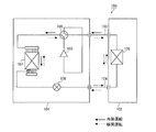
- FIG. 3 is a refrigerant circuit diagram illustrating the air-conditioning apparatus 100 according to Embodiment 1 of the present invention.
- an outdoor unit 101 and an indoor unit 102 are connected by a gas refrigerant pipe 103 and a liquid refrigerant pipe 104.
- the outdoor unit 101 includes a compressor 105, a four-way valve 106, an outdoor heat exchanger 107, and an expansion valve 108.
- the compressor 105 compresses and discharges the sucked refrigerant.
- the temperature of the refrigerant discharged from the compressor 105 is defined as a discharge temperature. Further, the surface temperature of the discharge pipe of the compressor 105 may be used as the discharge temperature.
- the operating frequency of the compressor 105 may be arbitrarily changed by, for example, an inverter circuit or the like, and the capacity of the compressor 105 for sending the refrigerant per unit time may be changed.
- the four-way valve 106 is a valve that switches the flow of the refrigerant between, for example, a cooling operation and a heating operation.
- the outdoor heat exchanger 107 performs heat exchange between the refrigerant and outdoor air.
- the outdoor heat exchanger 107 functions as a condenser during the cooling operation, and condenses and liquefies the refrigerant.
- the outdoor heat exchanger 107 functions as an evaporator during the heating operation, and evaporates and vaporizes the refrigerant.
- the expansion valve 108 is a flow control valve, and decompresses and expands the refrigerant.
- the expansion valve 108 is configured by, for example, an electronic expansion valve, the opening degree can be adjusted based on an instruction from a control device (not shown).
- the indoor unit 102 has an indoor heat exchanger 109.
- the indoor heat exchanger 109 performs, for example, heat exchange between air to be air-conditioned and a refrigerant.
- the indoor heat exchanger 109 functions as an evaporator during the cooling operation, and evaporates and vaporizes the refrigerant.
- the indoor heat exchanger 109 functions as a condenser during the heating operation, and condenses and liquefies the refrigerant.
- the flow of the refrigerant is switched by the four-way valve 106 of the outdoor unit 101, and the cooling operation or the heating operation can be realized.
- FIG. 4 is an external front view showing the indoor unit 102 of the air-conditioning apparatus 100 according to Embodiment 1 of the present invention.
- An indoor unit 102 shown in FIG. 4 includes a gas refrigerant pipe, which is a copper pipe, to an outdoor unit 101 that forms a general refrigerant circuit using a compressor 105, an outdoor heat exchanger 107, an expansion valve 108, a four-way valve 106, and the like.
- the connection is made by using a liquid refrigerant pipe 103 and 103.
- the indoor unit 102 can realize a cooling operation or a heating operation by switching the four-way valve 106.
- the indoor unit 102 is a wall-mounted type installed on a wall in a room that blows out conditioned air.
- the heat-exchanged conditioned air is blown to a blower fan 3 configured by a cross flow fan or the like, and is blown out from an outlet 4 located at a lower portion of the indoor unit 102.
- a vertical wind direction plate 5 and a left and right wind direction plate 6 are attached to the outlet 4 as wind direction devices. By changing the angles of the upper and lower wind direction plates 5 and the left and right wind direction plates 6, the direction of the airflow blown from the outlet 4 can be adjusted.
- a fan guard 7 is attached to the air outlet 4 for the purpose of preventing cuts caused by a user inserting a finger into the interior of the indoor unit 102 from the air outlet 4.
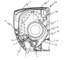
- FIG. 5 is a longitudinal sectional view showing the indoor unit 102 of the air-conditioning apparatus 100 according to Embodiment 1 of the present invention.
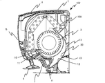
- FIG. 6 is a longitudinal sectional view showing the indoor unit 102 of the air-conditioning apparatus 100 according to Embodiment 1 of the present invention in a state where the outlet 4 is open.
- a filter 8 is attached to the suction port 2 for the purpose of preventing dust from entering the indoor unit 102.
- the indoor air taken in from the inlet 2 is subjected to heat exchange in the indoor heat exchanger 109.
- the conditioned air after the heat exchange blows out from the outlet 4 along the air passage 20 in the air passage member 10 including the front air passage member 11 and the rear air passage member 12 in accordance with the air flow generated by the rotation of the blower fan 3. And sent out to the room.
- the indoor unit 102 includes the rear housing 13 made of a thermoplastic resin.
- the air path member 10 is provided in the air path 20 through which the heat-exchanged conditioned air flows, and is made of a thermosetting resin.
- the air path member 10 includes a front air path member 11 supported by the rear housing 13 and a rear air path member 12 opposed to the front air path member 11 via the air path 20.
- the air passage 20 is configured to be surrounded by the front air passage member 11 and the rear air passage member 12.
- the rear air passage member 12 is superimposed on the surface of the rear housing 13 that is the air passage area 14 through which the conditioned air flows.
- the blowing temperature is the temperature of the airflow blown out from the blowing port 4.
- a value obtained by directly measuring the temperature of the blown airflow by a temperature sensor may be used.
- a value obtained by measuring the surface temperature of the heat transfer tube of the indoor heat exchanger 109 with a temperature sensor may be used as the blowout temperature.
- the average value of a predetermined number of measured values or the average value of the measured values within a predetermined time is constantly updated during operation, regardless of the above, and the latest value is used as the current blowout value. It is desirable to use as a temperature.
- the indoor heat exchanger 109 functions as a condenser.
- the maximum surface temperature near the inlet of the heat transfer tube of the indoor heat exchanger 109 rises to 90 ° C. or higher.
- the refrigerant used is R290
- the blowing temperature can be increased to 75 ° C.
- the refrigerant to be used is R410A or R32
- the maximum blowing temperature is 65 ° C.
- R290 is used as the refrigerant, a blowing temperature higher by about 10 ° C. than that of R410A or R32 can be realized.
- the blower fan 3, the upper and lower wind direction plates 5, the left and right wind direction plates 6, and the fan guard 7 are components of the indoor unit 102 that are located in the air passage 20 and are easily affected by the blowout temperature during the heating operation.
- the blower fan 3, the upper and lower wind direction plates 5, the left and right wind direction plates 6, and the fan guard 7 are provided by a thermosetting resin.
- the thermosetting resin is a strong resin material without softening of the resin due to heating. For this reason, the heat resistance of the indoor unit 102 can be improved by providing the components in the air passage 20 with a thermosetting resin.
- the thermosetting resin used include a phenol resin, a melamine resin, a polyurethane, and an epoxy resin.
- Phenol resin has a heat resistance of 150 ° C.
- Melamine resin has a heat resistance of 110 ° C.
- Polyurethane has a heat resistance of 90 ° C.
- Epoxy resin has a heat resistance of 150 ° C.
- the normal heat resistance temperature of the thermosetting resin is 90 ° C. or higher, and the thermal deformation of the resin due to the maximum surface temperature of the indoor heat exchanger 109 or the high hot air having the maximum blowing temperature of 75 ° C. in the first embodiment. Does not occur.
- the blower fan 3 and the fan guard 7 may be formed using metal.
- the normal heat-resistant temperature of the metal is 200 ° C. or higher, and no thermal deformation of the metal occurs due to the high hot air having the maximum blowing temperature of 75 ° C. in the first embodiment.
- the metal used include iron, copper, and aluminum. If the blower fan 3 is made of metal, there is a concern that the possibility of cuts by the blower fan 3 is increased as compared with the case where the blower fan 3 is made of resin. However, since the fan guard 7 is made of metal that is stronger than resin, the reliability with respect to cut resistance is improved.
- FIG. 7 is a perspective view showing rear housing 13 of indoor unit 102 of air-conditioning apparatus 100 according to Embodiment 1 of the present invention from the front side where air passage 20 is visible.
- FIG. 8 is a perspective view showing the rear housing 13 of the indoor unit 102 of the air-conditioning apparatus 100 according to Embodiment 1 of the present invention from the back side where the air passage 20 is not visible.
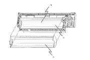
- FIG. 9 is an exploded perspective view showing rear housing 13 and rear air passage member 12 in indoor unit 102 of air-conditioning apparatus 100 according to Embodiment 1 of the present invention.
- FIG. 10 is a perspective view showing rear air path member 12 in indoor unit 102 of air-conditioning apparatus 100 according to Embodiment 1 of the present invention.
- the rear housing 13 is attached to a wall surface in the room, and supports the internal components, the front air path member 11, the front housing 15, and the like. For this reason, the rear housing 13 needs to have a conventional reference strength.
- the air path member 10 has a rear air path member 12 in addition to the front air path member 11.
- the rear air passage member 12 is superimposed on the surface where the conditioned air flows in the air passage region 14 of the rear housing 13.
- the rear air path member 12 is a component having a size that covers the entire air path area 14 conventionally formed on the rear housing 13.
- the rear air path member 12 since the rear air path member 12 has a size that reaches the entire air path area 14, a side end surface that supports the rear-side curved surface portion and the blower fans 3 at both ends of the curved surface portion. And a part.
- the rear casing 13 and the rear air path member 12 have claws (not shown) for coupling each other. By coupling the claws to each other, the rear housing 13 and the rear air path member 12 are integrated. As will be described later, a heat insulating area 16 is formed between the rear housing 13 and the rear air passage member 12. The rear housing 13 and the rear air path member 12 are integrated to form a heat-resistant air path structure having a laminated structure.
- the back air path member 12 shown in FIG. 10 is made of a thermosetting resin.
- the rear air path member 12 uses a thermosetting resin such as a phenol resin, a melamine resin, a polyurethane, or an epoxy resin to avoid thermal deformation of the indoor unit 102.
- the rear air path member 12 may be made of the same thermosetting resin as the blower fan 3, the upper and lower air direction plates 5, the left and right air direction plates 6, and the fan guard 7, or may be made of a different thermosetting resin.
- the normal heat-resistant temperature of the thermosetting resin is 90 ° C. or higher, and thermal deformation of the resin due to the high hot air having the maximum blowing temperature of 75 ° C. in the first embodiment does not occur in the rear air passage member 12.
- the rear housing 13 is made of a thermoplastic resin.
- the thermoplastic resin applied to the rear housing 13 includes polystyrene, ABS resin, polypropylene, polyethylene, and acrylic resin.
- Polystyrene has a heat resistance of 70 ° C.
- ABS resin has a heat resistance of 70 ° C.
- Polypropylene has a heat resistance of 80 ° C.
- Polyethylene has a heat resistance of 50 ° C.
- Acrylic resin has a heat resistance of 60 ° C.
- the normal heat-resistant temperature of the thermoplastic resin is about 70 ° C., and the thermoplastic resin may not be able to withstand the maximum blowing temperature of 80 ° C. in the first embodiment and may be deformed.
- the rear casing 13 does not face the air passage 20 of the indoor unit 102, and there is little concern about thermal deformation of the resin due to a high blowing temperature. Further, since the heat insulating region 16 described later is formed, the rear casing 13 is less likely to thermally deform the resin due to a high blowing temperature.
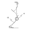
- FIG. 11 is a vertical cross-sectional view showing rear housing 13 of indoor unit 102 of air-conditioning apparatus 100 according to Embodiment 1 of the present invention.
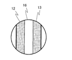
- FIG. 12 is an enlarged view showing part A in FIG. 11 of rear housing 13 of indoor unit 102 of air-conditioning apparatus 100 according to Embodiment 1 of the present invention.
- a heat insulating region 16 is formed between the rear air passage member 12 and the rear housing 13.
- the rear air path member 12, the heat insulating region 16, and the rear housing 13 are sequentially overlapped to form a laminated structure.
- the heat insulating region 16 more reliably avoids thermal deformation of the rear housing 13 due to heat transfer from the rear air passage member 12.
- the heat insulation area 16 may be an air heat insulation layer. Further, a heat insulating material may be provided in the heat insulating region 16. When the heat insulating region 16 is provided by a heat insulating material, a foamed plastic heat insulating material such as rigid urethane foam or polystyrene foam is used.
- R290 is used as the refrigerant for the indoor unit 102 of the air-conditioning apparatus 100 that performs the heating operation.
- the indoor unit 102 can blow out a warm air having a high blowout temperature of 75 ° C.
- the rear air passage member 12 that is easily affected by high warm air is provided by a thermosetting resin having high heat resistance, deterioration of the housing appearance and the air blowing characteristics due to thermal deformation of the rear air passage member 12 is prevented. Can be avoided.
- the rear housing 13 which is hardly affected by high warm air is provided by a thermoplastic resin which is less expensive than a thermosetting resin.
- the cost can be reduced as compared with the case where the entire rear housing 13 including the rear air passage member 12 is made of a thermosetting resin.
- the rear housing 13 can apply the conventional product almost as it is, can secure the strength of the conventional design standard, and even if the rear housing 13 supports the internal components, the front wind path member 11, the front housing 15, and the like, Insufficient strength does not affect use durability.
- the other units in the air passage 20 are configured by applying a thermosetting resin or a metal, and the indoor unit 102 of the air-conditioning apparatus 100 including the heat-resistant air passage 20 can be realized.
- indoor unit 102 of air-conditioning apparatus 100 uses R290 as the refrigerant, and is a warm air having an outlet temperature of 70 ° C to 75 ° C.
- the critical temperature of R290 is 96.7 ° C.
- the critical temperature of R410A is 71.4 ° C.
- the critical temperature of R32 is 78.1 ° C. Therefore, in the R290, when a high temperature air of 75 ° C. is blown out, the condensation temperature is increased without approaching the critical temperature on the Mollier diagram, and the enthalpy difference between the saturated liquid line and the saturated vapor line is not reduced. , The condensation capacity does not decrease.
- the indoor unit 102 of the air conditioner 100 includes the indoor heat exchanger 109.
- the discharge temperature of the compressor 105 in the refrigeration cycle circuit is 100 ° C. or less, and the suction air is heat-exchanged into warm air in the condensing process in which the condensing temperature in the indoor heat exchanger 109 is from 70 ° C. to 80 ° C.
- the condensing temperature in the indoor heat exchanger 109 is reduced from 70 ° C. to 80 ° C. while maintaining the heat resistance performance of the compressor 105, which is a mechanical element, almost equal to the conventional design in which the discharge temperature is 100 ° C. or less.
- the suction air can exchange heat with the hot air having a blowing temperature of 70 ° C to 75 ° C. For this reason, high heat exchange efficiency is exhibited without deteriorating the condensing capacity, and high-temperature air with a high condensing temperature of 70 ° C. to 75 ° C. can be blown out from the indoor unit 102.
- the indoor unit 102 of the air conditioner 100 includes the air passage member 10 made of a thermosetting resin in the air passage 20 through which the heat-exchanged conditioned air flows.
- thermosetting resin is less likely to be thermally deformed and has excellent heat resistance.
- the air path 20 composed of the air path member 10 made of a thermosetting resin does not thermally deform even when hot air having a blowing temperature of 75 ° C. flows, thereby avoiding deterioration of the housing appearance and the blowing characteristics. it can.
- the indoor unit 102 of the air-conditioning apparatus 100 includes the rear housing 13 made of a thermoplastic resin.
- the air path member 10 has a rear air path member 12 that is superimposed on a surface where conditioned air flows in an air path area 14 of the rear housing 13.
- the rear housing 13 supports all the internal components of the indoor unit 102 and the front housing 15. For this reason, it is necessary to secure the strength of the rear housing 13 by the conventional design. Since the rear air path member 12 is overlapped only on the air path area 14 of the rear housing 13, heat resistance is increased only in a portion which is easily affected by high warm air. As a result, while the strength of the rear housing 13 is ensured by the conventional design, the amount of the expensive thermosetting resin used for the rear air passage member 12 can be reduced and the cost can be reduced.
- the heat insulating region 16 is formed between the rear air passage member 12 and the rear housing 13.
- the heat insulating region 16 is insulated and the rear housing 13 made of thermoplastic resin is affected by the heat transfer. hard. Further, since the heat insulating region 16 insulates the heat transfer of the conditioned air flowing through the air passage 20, the occurrence of dew condensation on the rear side of the rear housing 13 behind the air passage region 14 during the cooling operation can be suppressed. For this reason, there is no need to provide a heat insulating material on the back side of the air passage region 14 of the rear housing 13 or the amount of heat insulating material provided on the back side can be reduced, and cost can be reduced.
- the heat insulating region 16 is an air heat insulating layer.
- the heat insulating material is provided in the heat insulating region 16.
- the air passage member 10 has the front air passage member 11 supported by the rear housing 13.
- the apparatus includes a blower fan 3 made of a thermosetting resin, a fan guard 7, and upper and lower wind direction plates 5 and left and right wind direction plates 6 as wind direction devices.
- the air passage member 10 has the front air passage member 11 supported by the rear housing 13.
- the indoor unit 102 of the air conditioner 100 includes a vertical wind direction plate 5 and a left and right wind direction plate 6 as wind direction devices made of a thermosetting resin.
- the indoor unit 102 of the air conditioner 100 includes a metal blower fan 3 and a fan guard 7.
- cut resistance to the metal blower fan 3 can be obtained by the metal fan guard 7.
- the air conditioner 100 includes the indoor unit 102 of the air conditioner 100 described above.
Landscapes
- Engineering & Computer Science (AREA)
- Mechanical Engineering (AREA)
- General Engineering & Computer Science (AREA)
- Chemical & Material Sciences (AREA)
- Combustion & Propulsion (AREA)
- Physics & Mathematics (AREA)
- Thermal Sciences (AREA)
- Air Filters, Heat-Exchange Apparatuses, And Housings Of Air-Conditioning Units (AREA)
- Air-Conditioning Room Units, And Self-Contained Units In General (AREA)
- Air Conditioning Control Device (AREA)
Abstract
空気調和装置の室内機は、冷媒にR290を用い、吹出温度が70℃から75℃の温風である。
Description
本発明は、高い温風を吹出す空気調和装置の室内機及び空気調和装置に関する。
従来、R410A又はR32を用いて温風を吹出す空気調和装置が知られている(たとえば、特許文献1参照)。特許文献1の技術では、R32を冷凍サイクル回路の冷媒に用い、暖房又は冷房といった空気調和が行われている。
R410Aの臨界温度は、71.4℃である。R32の臨界温度は、78.1℃である。ここで、モリエル線図上では、凝縮温度が臨界温度に近づくに伴って飽和液線と飽和蒸気線とのエンタルピー差が縮小し、凝縮能力が小さくなる。このため、臨界温度が低いR410A又はR32の暖房運転では、凝縮温度を高くした高い温風を室内機から吹出すことができないという課題がある。
本発明は、上記課題を解決するためのものであり、暖房運転時に高い温風を吹出す空気調和装置の室内機及び空気調和装置を提供することを目的とする。
本発明に係る空気調和装置の室内機は、冷媒にR290を用い、吹出温度が70℃から75℃の温風であるものである。
本発明に係る空気調和装置は、上記の空気調和装置の室内機を備えるものである。
本発明に係る空気調和装置の室内機及び空気調和装置によれば、冷媒にR290を用い、吹出温度が70℃から75℃の温風である。ここで、R290の臨界温度は、96.7℃である。このため、臨界温度が高いR290の暖房運転では、凝縮温度を高くした吹出温度が70℃から75℃の高い温風が室内機から吹出可能である。したがって、暖房運転時に高い温風が吹出可能である。
以下、図面に基づいて本発明の実施の形態について説明する。なお、各図において、同一の符号を付したものは、同一の又はこれに相当するものであり、これは明細書の全文において共通している。また、断面図の図面においては、視認性に鑑みて適宜ハッチングを省略している。さらに、明細書全文に示す構成要素の形態は、あくまで例示であってこれらの記載に限定されるものではない。
実施の形態1.
<R290の使用>
図1は、従来の空気調和装置で使用しているR32の特性を現すモリエル線図である。図2は、本発明の実施の形態1に係るR290の特性を現すモリエル線図である。
<R290の使用>
図1は、従来の空気調和装置で使用しているR32の特性を現すモリエル線図である。図2は、本発明の実施の形態1に係るR290の特性を現すモリエル線図である。
図1、図2に示すモリエル線図上の冷凍サイクル回路は、A-B間の減圧装置による等エンタルピー変化と、B-C間の蒸発器による等温等圧変化と、C-D間の圧縮機による断熱圧縮変化と、D-A間の凝縮器による等圧変化と、により構成される理論サイクルである。
冷凍サイクル回路は、過熱度を1℃とし、過冷却度を6℃とし、D-A間での凝縮温度が75℃の暖房運転の場合を提示している。図1の冷媒にR32を用いた場合のD点の圧縮機の吐出温度は155.1℃を示す。図2の冷媒にR290を用いた場合のD点の圧縮機の吐出温度は98.1℃を示す。
用いる冷媒がR32では吐出温度が155.1℃と高くなり過ぎ、圧縮機が故障する可能性が高く、凝縮温度75℃の実現は困難である。また、冷媒がR32では、臨界点が78.1℃であるため、D-A間の凝縮行程では、等圧変化領域が少なく、圧縮機の仕事に対する効果が得られない。
これに対し、用いる冷媒がR290では吐出温度が98.1℃と従来設計の耐熱性の圧縮機での許容範囲にある。そして、室内熱交換器109での凝縮温度が70℃から80℃の凝縮行程にて吸込空気が温風に熱交換できる。凝縮行程の領域も圧縮機の仕事に対して有効に働く。このように、用いる冷媒がR290では、吐出温度及び圧力の両面から70℃から75℃の温風を吹出す空気調和装置100が実現可能である。
実施の形態1では、空気調和装置100の性能向上及びノンフロン冷媒を利用した環境保護の観点から、空気調和装置100の冷媒としてR290が使用される。つまり、空気調和装置100の室内機102は、冷媒にR290を用い、吹出温度が70℃以上75℃以下という温風を吹出可能である。
R290は、プロパンという名称で知られる無色無臭の可燃性冷媒であり、分子式がC3H8である。そのGWP(Global Warming Potential:地球温暖化係数)は3であり、代替フロン冷媒であるR410A又はR32よりも低いGWPを示す。
<空気調和装置100の構成>
図3は、本発明の実施の形態1に係る空気調和装置100を示す冷媒回路図である。図3に示す空気調和装置100は、室外機101と室内機102とをガス冷媒配管103及び液冷媒配管104によって接続されている。
図3は、本発明の実施の形態1に係る空気調和装置100を示す冷媒回路図である。図3に示す空気調和装置100は、室外機101と室内機102とをガス冷媒配管103及び液冷媒配管104によって接続されている。
室外機101は、圧縮機105、四方弁106、室外熱交換器107及び膨張弁108を有する。
圧縮機105は、吸入した冷媒を圧縮して吐出する。圧縮機105から吐出された冷媒の温度を吐出温度とする。また、圧縮機105の吐出配管の表面温度を吐出温度としてもよい。圧縮機105は、たとえばインバータ回路などにより、運転周波数を任意に変化させ、圧縮機105の単位時間あたりの冷媒を送り出す容量を変化させてもよい。
四方弁106は、たとえば冷房運転時と暖房運転時とによって冷媒の流れを切り換える弁である。
室外熱交換器107は、冷媒と室外の空気との熱交換を行う。室外熱交換器107は、冷房運転時に凝縮器として機能し、冷媒を凝縮して液化させる。室外熱交換器107は、暖房運転時に蒸発器として機能し、冷媒を蒸発させ、気化させる。
膨張弁108は、流量制御弁であり、冷媒を減圧して膨張させる。膨張弁108は、たとえば電子式膨張弁などで構成された場合には、図示しない制御装置などの指示に基づいて開度調整を行える。
室内機102は、室内熱交換器109を有する。室内熱交換器109は、たとえば空調対象の空気と冷媒との熱交換を行う。室内熱交換器109は、冷房運転時に蒸発器として機能し、冷媒を蒸発させ、気化させる。室内熱交換器109は、暖房運転時に凝縮器として機能し、冷媒を凝縮して液化させる。
以上のように空気調和装置100を構成することにより、室外機101の四方弁106によって冷媒の流れを切り換え、冷房運転又は暖房運転が実現できる。
<室内機102の概要>
図4は、本発明の実施の形態1に係る空気調和装置100の室内機102を示す外観正面図である。図4に示す室内機102は、圧縮機105、室外熱交換器107、膨張弁108及び四方弁106などを用いて一般的な冷媒回路を構成する室外機101に、銅配管であるガス冷媒配管103及び液冷媒配管104を用いて接続される。室内機102は、四方弁106を切り替えることによって冷房運転又は暖房運転を実現できる。室内機102は、調和空気を吹出す室内の壁に設置された壁掛け型である。
図4は、本発明の実施の形態1に係る空気調和装置100の室内機102を示す外観正面図である。図4に示す室内機102は、圧縮機105、室外熱交換器107、膨張弁108及び四方弁106などを用いて一般的な冷媒回路を構成する室外機101に、銅配管であるガス冷媒配管103及び液冷媒配管104を用いて接続される。室内機102は、四方弁106を切り替えることによって冷房運転又は暖房運転を実現できる。室内機102は、調和空気を吹出す室内の壁に設置された壁掛け型である。
室内機102の上部に位置する吸込口2から吸込まれた室内空気は、室内機102内で室内熱交換器109の冷媒と熱交換される。熱交換された調和空気は、クロスフローファンなどで構成された送風ファン3に送風され、室内機102の下部に位置する吹出口4から吹出される。吹出口4には、風向装置として上下風向板5と左右風向板6とが取り付けられている。上下風向板5及び左右風向板6の角度を変えることにより、吹出口4から吹出される気流の方向が調整できる。また、吹出口4から室内機102内部に使用者が指を挿入することによる切創防止を目的として、吹出口4にファンガード7が取り付けられている。
図5は、本発明の実施の形態1に係る空気調和装置100の室内機102を示す縦断面図である。図6は、本発明の実施の形態1に係る空気調和装置100の室内機102を吹出口4が開いた状態で示す縦断面図である。
図5、図6に示すように、室内機102内への埃の進入防止を目的として、吸込口2にはフィルタ8が取り付けられている。吸込口2から取り込まれた室内空気は、室内熱交換器109にて熱交換される。熱交換後の調和空気は、送風ファン3の回転により生じる気流に従い、前面風路部材11及び背面風路部材12から構成された風路部材10内の風路20に沿いながら吹出口4から吹出され、室内へと送り出される。
すなわち、室内機102は、熱可塑性樹脂製の背面筐体13を備える。風路部材10は、熱交換された調和空気の流れる風路20に熱硬化性樹脂製で設けられている。風路部材10は、背面筐体13に支持された前面風路部材11と、前面風路部材11と風路20を介して対向した背面風路部材12と、を有する。風路20は、前面風路部材11と背面風路部材12とに囲まれて構成されている。後述するように背面風路部材12は、背面筐体13における風路領域14である調和空気が流れる表面に重ねられる。
なお、ここで吹出温度とは、吹出口4から吹き出される空気流の温度である。吹出温度には、吹出される空気流の温度を直接温度センサーにて測定した値を使用してもよい。また、吹出温度には、室内熱交換器109の伝熱管の表面温度を温度センサーにて測定した値を使用してもよい。そして、吹出温度には、上記のどちらであっても予め定められた個数の測定値の平均値又は所定時間内の測定値の平均値を運転中に常時更新し、その最新値を現在の吹出温度として用いることが望ましい。
このように構成された室内機102の暖房運転時では、室内熱交換器109が凝縮器として作用する。室内熱交換器109の伝熱管の入口付近の最高表面温度は90℃以上まで上昇する。用いる冷媒がR290の場合の吹出温度は、75℃まで上昇可能となる。用いる冷媒がR410A又はR32である場合には、最高吹出温度が65℃である。このように、実施の形態1では、R290を冷媒に用いているので、R410A又はR32よりも約10℃高い吹出温度が実現できる。
<室内機102の部品の詳細>
送風ファン3、上下風向板5、左右風向板6及びファンガード7は、風路20内に位置し、暖房運転時の吹出温度による影響を受け易い室内機102の構成部品である。送風ファン3、上下風向板5、左右風向板6及びファンガード7は、熱硬化性樹脂製で設けられている。熱硬化性樹脂は、加熱による樹脂の軟化が無く、強固な樹脂材料である。このため、風路20中の部品群を熱硬化性樹脂製で設けることにより、室内機102の耐熱性が向上できる。使用する熱硬化性樹脂としては、フェノール樹脂、メラミン樹脂、ポリウレタン、又は、エポキシ樹脂などがある。フェノール樹脂は、150℃の耐熱性を有する。メラミン樹脂は、110℃の耐熱性を有する。ポリウレタンは、90℃の耐熱性を有する。エポキシ樹脂は、150℃の耐熱性を有する。このように、熱硬化性樹脂の常用耐熱温度は、90℃以上であり、実施の形態1での室内熱交換器109の最高表面温度あるいは最高吹出温度75℃の高い温風による樹脂の熱変形が発生しない。
送風ファン3、上下風向板5、左右風向板6及びファンガード7は、風路20内に位置し、暖房運転時の吹出温度による影響を受け易い室内機102の構成部品である。送風ファン3、上下風向板5、左右風向板6及びファンガード7は、熱硬化性樹脂製で設けられている。熱硬化性樹脂は、加熱による樹脂の軟化が無く、強固な樹脂材料である。このため、風路20中の部品群を熱硬化性樹脂製で設けることにより、室内機102の耐熱性が向上できる。使用する熱硬化性樹脂としては、フェノール樹脂、メラミン樹脂、ポリウレタン、又は、エポキシ樹脂などがある。フェノール樹脂は、150℃の耐熱性を有する。メラミン樹脂は、110℃の耐熱性を有する。ポリウレタンは、90℃の耐熱性を有する。エポキシ樹脂は、150℃の耐熱性を有する。このように、熱硬化性樹脂の常用耐熱温度は、90℃以上であり、実施の形態1での室内熱交換器109の最高表面温度あるいは最高吹出温度75℃の高い温風による樹脂の熱変形が発生しない。
送風ファン3及びファンガード7は、金属を用いて成形してもよい。金属の常用耐熱温度は、200℃以上であり、実施の形態1での最高吹出温度75℃の高い温風による金属の熱変形が発生しない。使用する金属としては、鉄、銅、又は、アルミニウムなどがある。送風ファン3が金属製であると、樹脂製の場合よりも送風ファン3による切創の可能性が増大する懸念がある。しかし、ファンガード7が樹脂製より頑丈な金属製であることにより、耐切創に対する信頼性が向上する。
<背面筐体13及び背面風路部材12の詳細>
図7は、本発明の実施の形態1に係る空気調和装置100の室内機102における背面筐体13を風路20が見える正面側から示す斜視図である。図8は、本発明の実施の形態1に係る空気調和装置100の室内機102における背面筐体13を風路20の見えない裏側から示す斜視図である。図9は、本発明の実施の形態1に係る空気調和装置100の室内機102における背面筐体13と背面風路部材12とを示す分解斜視図である。図10は、本発明の実施の形態1に係る空気調和装置100の室内機102における背面風路部材12を示す斜視図である。
図7は、本発明の実施の形態1に係る空気調和装置100の室内機102における背面筐体13を風路20が見える正面側から示す斜視図である。図8は、本発明の実施の形態1に係る空気調和装置100の室内機102における背面筐体13を風路20の見えない裏側から示す斜視図である。図9は、本発明の実施の形態1に係る空気調和装置100の室内機102における背面筐体13と背面風路部材12とを示す分解斜視図である。図10は、本発明の実施の形態1に係る空気調和装置100の室内機102における背面風路部材12を示す斜視図である。
図7~図9に示すように、背面筐体13は、室内の壁面に取り付けられ、内部部品、前面風路部材11及び前面筐体15などを支持している。このため、背面筐体13は、従来基準の強度が必要である。風路部材10は、前面風路部材11の他に、背面風路部材12を有する。図9に示すように、背面風路部材12は、背面筐体13における風路領域14にて調和空気が流れる表面に重ねられる。背面風路部材12は、従来、背面筐体13に形成されていた風路領域14全体に被さる大きさの部品である。図9、図10に示すように、背面風路部材12は、風路領域14全体に至る大きさのため、背面側の曲面部とその曲面部の両端側の送風ファン3を支持する側端面部とを有する。
背面筐体13と背面風路部材12とは、互いを結合する図示しないツメ部を有する。互いのツメ部が結合することにより、背面筐体13と背面風路部材12とが一体化されている。なお、後述するように背面筐体13と背面風路部材12との間には、断熱領域16が形成されている。背面筐体13と背面風路部材12とは、一体化して積層構造の耐熱性風路構造を構成している。
図10に示す背面風路部材12は、熱硬化性樹脂製である。背面風路部材12は、フェノール樹脂、メラミン樹脂、ポリウレタン、又は、エポキシ樹脂などの熱硬化性樹脂を適用し、室内機102の熱変形を回避する。背面風路部材12は、送風ファン3、上下風向板5、左右風向板6及びファンガード7と同じ熱硬化性樹脂製でもよいし、異なる熱硬化性樹脂製でもよい。熱硬化性樹脂の常用耐熱温度は、90℃以上であり、実施の形態1での最高吹出温度75℃の高い温風による樹脂の熱変形が背面風路部材12に発生しない。
背面筐体13は、熱可塑性樹脂製である。背面筐体13に適用する熱可塑性樹脂は、ポリスチレン、ABS樹脂、ポリプロピレン、ポリエチレン、又は、アクリル樹脂などがある。ポリスチレンは、70℃の耐熱性を有する。ABS樹脂は、70℃の耐熱性を有する。ポリプロピレンは、80℃の耐熱性を有する。ポリエチレンは、50℃の耐熱性を有する。アクリル樹脂は、60℃の耐熱性を有する。このように、熱可塑性樹脂の常用耐熱温度は70℃程度であり、実施の形態1での最高吹出温度80℃に対して耐え切れず変形する可能性がある。しかし、背面筐体13は、室内機102の風路20に面しておらず、高い吹出温度による樹脂の熱変形に対する懸念が少ない。さらに、後述の断熱領域16が形成されているので、背面筐体13は、高い吹出温度による樹脂の熱変形をし難い。
<背面筐体13と背面風路部材12との積層構造>
図11は、本発明の実施の形態1に係る空気調和装置100の室内機102における背面筐体13を示す縦断面図である。図12は、本発明の実施の形態1に係る空気調和装置100の室内機102における背面筐体13の図11におけるA部を示す拡大図である。
図11は、本発明の実施の形態1に係る空気調和装置100の室内機102における背面筐体13を示す縦断面図である。図12は、本発明の実施の形態1に係る空気調和装置100の室内機102における背面筐体13の図11におけるA部を示す拡大図である。
図11、図12に示すように、背面風路部材12と背面筐体13との間には、断熱領域16が形成されている。背面風路部材12と断熱領域16と背面筐体13とが順に重なって積層構造を構成している。断熱領域16は、背面風路部材12からの伝熱による背面筐体13の熱変形の回避をより確実にする。
断熱領域16は、空気断熱層でもよい。また、断熱領域16には、断熱材が設けられてもよい。断熱領域16が断熱材によって設けられている場合には、硬質ウレタンフォームあるいはポリスチレンフォームなどの発泡プラスチック系断熱材が使用される。
<室内機102の効果>
以上のように、暖房運転する空気調和装置100の室内機102について、冷媒としてR290を使用する。これにより、室内機102は、最高吹出温度として75℃の高い温風を吹出可能である。ここで、高い温風による影響を受け易い背面風路部材12を耐熱性の高い熱硬化性樹脂製で設けているため、背面風路部材12の熱変形による筐体外観及び送風特性の劣化が回避できる。高い温風による影響を受け難い背面筐体13は、熱硬化性樹脂よりも安価な熱可塑性樹脂製で設けられている。このため、背面風路部材12を含む背面筐体13全体を熱硬化性樹脂製で構成する場合と比較して、コストが軽減できる。また、背面筐体13は、従来製品をほとんどそのまま適用でき、従来設計基準の強度が確保でき、背面筐体13に内部部品、前面風路部材11及び前面筐体15などが支持されても、強度不足による使用耐久性に悪影響が及ばない。さらに、背面風路部材12と背面筐体13との間に空気層又は断熱材の断熱領域16を形成した積層構造に構成されることにより、背面筐体13への断熱効果が強化され、熱可塑性樹脂製の背面筐体13の熱変形の回避がより確実となる。その他の風路20内の部品群については、熱硬化性樹脂又は金属を適用して構成するなどし、耐熱性の風路20を備える空気調和装置100の室内機102が実現できる。
以上のように、暖房運転する空気調和装置100の室内機102について、冷媒としてR290を使用する。これにより、室内機102は、最高吹出温度として75℃の高い温風を吹出可能である。ここで、高い温風による影響を受け易い背面風路部材12を耐熱性の高い熱硬化性樹脂製で設けているため、背面風路部材12の熱変形による筐体外観及び送風特性の劣化が回避できる。高い温風による影響を受け難い背面筐体13は、熱硬化性樹脂よりも安価な熱可塑性樹脂製で設けられている。このため、背面風路部材12を含む背面筐体13全体を熱硬化性樹脂製で構成する場合と比較して、コストが軽減できる。また、背面筐体13は、従来製品をほとんどそのまま適用でき、従来設計基準の強度が確保でき、背面筐体13に内部部品、前面風路部材11及び前面筐体15などが支持されても、強度不足による使用耐久性に悪影響が及ばない。さらに、背面風路部材12と背面筐体13との間に空気層又は断熱材の断熱領域16を形成した積層構造に構成されることにより、背面筐体13への断熱効果が強化され、熱可塑性樹脂製の背面筐体13の熱変形の回避がより確実となる。その他の風路20内の部品群については、熱硬化性樹脂又は金属を適用して構成するなどし、耐熱性の風路20を備える空気調和装置100の室内機102が実現できる。
<実施の形態1の効果>
実施の形態1によれば、空気調和装置100の室内機102は、冷媒にR290を用い、吹出温度が70℃から75℃の温風である。
実施の形態1によれば、空気調和装置100の室内機102は、冷媒にR290を用い、吹出温度が70℃から75℃の温風である。
この構成によれば、R290の臨界温度は、96.7℃である。一方、R410Aの臨界温度は、71.4℃である。R32の臨界温度は、78.1℃である。そのため、R290では、75℃の高い温風を吹出す場合に、モリエル線図上において、凝縮温度が臨界温度に近づかずに高められ、飽和液線と飽和蒸気線とのエンタルピー差が縮小せず、凝縮能力が小さくならない。このため、臨界温度がR410A及びR32よりも高いR290の暖房運転では、凝縮能力を低下させずに凝縮温度を高くした吹出温度として70℃から75℃の高い温風が室内機102から吹出可能である。これにより、燃焼系の暖房機器と同等に温かい温風が吹出し、使用者の快適感が満たされる。このように、暖房運転時に高い温風が吹出可能である。
実施の形態1によれば、空気調和装置100の室内機102は、室内熱交換器109を備える。冷凍サイクル回路内の圧縮機105の吐出温度が100℃以下であり、室内熱交換器109での凝縮温度が70℃から80℃の凝縮行程にて吸込空気が温風に熱交換される。
この構成によれば、機械要素である圧縮機105の耐熱性能を吐出温度が100℃以下の従来設計とほぼ同等に維持しながら、室内熱交換器109での凝縮温度が70℃から80℃の凝縮行程にて吸込空気が吹出温度として70℃から75℃の温風に熱交換できる。このため、凝縮能力を低下させずに高い熱交換効率が発揮され、かつ、凝縮温度を高くした吹出温度が70℃から75℃の高い温風が室内機102から吹出可能である。
実施の形態1によれば、空気調和装置100の室内機102は、熱交換された調和空気が流れる風路20に熱硬化性樹脂製の風路部材10を備える。
この構成によれば、熱硬化性樹脂が熱変形し難く耐熱性に優れる。このため、熱硬化性樹脂製の風路部材10で構成された風路20は、吹出温度が75℃の高い温風が流れても熱変形せず、筐体外観及び送風特性の劣化が回避できる。
実施の形態1によれば、空気調和装置100の室内機102は、熱可塑性樹脂製の背面筐体13を備える。風路部材10は、背面筐体13における風路領域14にて調和空気が流れる表面に重ねられる背面風路部材12を有する。
この構成によれば、背面筐体13は、室内機102の内部部品及び前面筐体15を全て支持している。このため、背面筐体13は、従来設計による強度確保が必要である。背面風路部材12は、背面筐体13の風路領域14だけに重ねられるので、高い温風による影響を受け易い部分のみ耐熱性が高められる。これにより、背面筐体13が従来設計による強度確保されつつ、背面風路部材12に用いる高価な熱硬化性樹脂量を削減して低コスト化が図れる。
実施の形態1によれば、背面風路部材12と背面筐体13との間には、断熱領域16が形成されている。
この構成によれば、高い温風が風路20を流れて背面風路部材12が高温化しても、断熱領域16が断熱し、熱可塑性樹脂製の背面筐体13が伝熱による影響を受け難い。また、断熱領域16が風路20を流れる調和空気の伝熱を断熱するので、冷房運転時に背面筐体13の風路領域14の裏側での結露の発生が抑制できる。このため、背面筐体13の風路領域14の裏側に断熱材を設ける必要が無くなったり、裏側に設ける断熱材量が削減できたりし、低コスト化が図れる。
実施の形態1によれば、断熱領域16は、空気断熱層である。
この構成によれば、余計な部材を設ける必要がなく、低コスト化が図れる。
実施の形態1によれば、断熱領域16には、断熱材が設けられている。
この構成によれば、断熱材によって断熱領域16に高い断熱性能が得られる。
実施の形態1によれば、風路部材10は、背面筐体13に支持された前面風路部材11を有する。熱硬化性樹脂製の送風ファン3とファンガード7と風向装置としての上下風向板5及び左右風向板6とを備える。
この構成によれば、高い温風が吹出す室内機102の部品群に耐熱性が得られる。
実施の形態1によれば、風路部材10は、背面筐体13に支持された前面風路部材11を有する。空気調和装置100の室内機102は、熱硬化性樹脂製の風向装置としての上下風向板5及び左右風向板6を備える。空気調和装置100の室内機102は、金属製の送風ファン3とファンガード7とを備える。
この構成によれば、金属製の送風ファン3に対する耐切創性が金属製のファンガード7で得られる。
実施の形態1によれば、空気調和装置100は、上記の空気調和装置100の室内機102を備える。
この構成によれば、空気調和装置100が備える室内機102において、臨界温度がR410A及びR32よりも高いR290の暖房運転では、凝縮能力を低下させずに凝縮温度を高くした吹出温度として75℃の高い温風が室内機102から吹出可能である。
2 吸込口、3 送風ファン、4 吹出口、5 上下風向板、6 左右風向板、7 ファンガード、8 フィルタ、10 風路部材、11 前面風路部材、12 背面風路部材、13 背面筐体、14 風路領域、15 前面筐体、16 断熱領域、20 風路、100 空気調和装置、101 室外機、102 室内機、103 ガス冷媒配管、104 液冷媒配管、105 圧縮機、106 四方弁、107 室外熱交換器、108 膨張弁、109 室内熱交換器。
Claims (10)
- 冷媒にR290を用い、吹出温度が70℃から75℃の温風である空気調和装置の室内機。
- 熱交換器を備え、
冷凍サイクル回路内の圧縮機の吐出温度が100℃以下であり、前記熱交換器での凝縮温度が70℃から80℃の凝縮行程にて吸込空気が前記温風に熱交換される請求項1に記載の空気調和装置の室内機。 - 熱交換された調和空気が流れる風路に熱硬化性樹脂製の風路部材を備える請求項1又は2に記載の空気調和装置の室内機。
- 熱可塑性樹脂製の背面筐体を備え、
前記風路部材は、前記背面筐体における風路領域にて調和空気が流れる表面に重ねられる背面風路部材を有する請求項3に記載の空気調和装置の室内機。 - 前記背面風路部材と前記背面筐体との間には、断熱領域が形成される請求項4に記載の空気調和装置の室内機。
- 前記断熱領域は、空気断熱層である請求項5に記載の空気調和装置の室内機。
- 前記断熱領域には、断熱材が設けられる請求項5に記載の空気調和装置の室内機。
- 前記風路部材は、前記背面筐体に支持された前面風路部材を有し、
熱硬化性樹脂製のファンとファンガードと風向装置とを備える請求項3~7のいずれか1項に記載の空気調和装置の室内機。 - 前記風路構成部材は、前記背面筐体に支持された前面風路部材を有し、
熱硬化性樹脂製の風向装置を備え、
金属製のファンとファンガードとを備える請求項3~7のいずれか1項に記載の空気調和装置の室内機。 - 請求項1~9のいずれか1項に記載の空気調和装置の室内機を備える空気調和装置。
Priority Applications (4)
| Application Number | Priority Date | Filing Date | Title |
|---|---|---|---|
| JP2020528563A JP6921325B2 (ja) | 2018-07-03 | 2018-07-03 | 空気調和装置の室内機及び空気調和装置 |
| PCT/JP2018/025145 WO2020008514A1 (ja) | 2018-07-03 | 2018-07-03 | 空気調和装置の室内機及び空気調和装置 |
| DE112018007794.2T DE112018007794B4 (de) | 2018-07-03 | 2018-07-03 | Innenraumeinheit einer Klimaanlage und Klimaanlage |
| CN201880095212.9A CN112352130A (zh) | 2018-07-03 | 2018-07-03 | 空调装置的室内机以及空调装置 |
Applications Claiming Priority (1)
| Application Number | Priority Date | Filing Date | Title |
|---|---|---|---|
| PCT/JP2018/025145 WO2020008514A1 (ja) | 2018-07-03 | 2018-07-03 | 空気調和装置の室内機及び空気調和装置 |
Publications (1)
| Publication Number | Publication Date |
|---|---|
| WO2020008514A1 true WO2020008514A1 (ja) | 2020-01-09 |
Family
ID=69060835
Family Applications (1)
| Application Number | Title | Priority Date | Filing Date |
|---|---|---|---|
| PCT/JP2018/025145 Ceased WO2020008514A1 (ja) | 2018-07-03 | 2018-07-03 | 空気調和装置の室内機及び空気調和装置 |
Country Status (4)
| Country | Link |
|---|---|
| JP (1) | JP6921325B2 (ja) |
| CN (1) | CN112352130A (ja) |
| DE (1) | DE112018007794B4 (ja) |
| WO (1) | WO2020008514A1 (ja) |
Citations (6)
| Publication number | Priority date | Publication date | Assignee | Title |
|---|---|---|---|---|
| JPH043844A (ja) * | 1990-04-20 | 1992-01-08 | Hitachi Ltd | 空気調和機の制御方法 |
| JPH10176867A (ja) * | 1996-12-13 | 1998-06-30 | Toshiba Corp | 空気調和装置 |
| JP2005015634A (ja) * | 2003-06-26 | 2005-01-20 | Matsushita Electric Ind Co Ltd | 混合冷媒とそれを用いた冷凍サイクル装置 |
| JP2010203699A (ja) * | 2009-03-04 | 2010-09-16 | Mitsubishi Electric Corp | 空気調和装置 |
| JP2012093072A (ja) * | 2010-10-27 | 2012-05-17 | Teratekku:Kk | 空調機用外付け式フラップ装置 |
| JP2014149095A (ja) * | 2013-01-31 | 2014-08-21 | Fujitsu General Ltd | 空気調和機 |
Family Cites Families (4)
| Publication number | Priority date | Publication date | Assignee | Title |
|---|---|---|---|---|
| EP1752714A1 (en) * | 2004-04-15 | 2007-02-14 | Daikin Industries, Ltd. | Air conditioner |
| JP3763315B2 (ja) * | 2004-08-25 | 2006-04-05 | ダイキン工業株式会社 | ファンケーシングの製造方法 |
| JP6252392B2 (ja) * | 2014-07-23 | 2017-12-27 | 三菱電機株式会社 | 空気調和機の室内機 |
| CN104325989B (zh) * | 2014-11-03 | 2017-03-08 | 无锡金鑫集团股份有限公司 | 一种有轨电车空调风道结构所用材料的制备方法 |
-
2018
- 2018-07-03 CN CN201880095212.9A patent/CN112352130A/zh active Pending
- 2018-07-03 DE DE112018007794.2T patent/DE112018007794B4/de not_active Expired - Fee Related
- 2018-07-03 WO PCT/JP2018/025145 patent/WO2020008514A1/ja not_active Ceased
- 2018-07-03 JP JP2020528563A patent/JP6921325B2/ja not_active Expired - Fee Related
Patent Citations (6)
| Publication number | Priority date | Publication date | Assignee | Title |
|---|---|---|---|---|
| JPH043844A (ja) * | 1990-04-20 | 1992-01-08 | Hitachi Ltd | 空気調和機の制御方法 |
| JPH10176867A (ja) * | 1996-12-13 | 1998-06-30 | Toshiba Corp | 空気調和装置 |
| JP2005015634A (ja) * | 2003-06-26 | 2005-01-20 | Matsushita Electric Ind Co Ltd | 混合冷媒とそれを用いた冷凍サイクル装置 |
| JP2010203699A (ja) * | 2009-03-04 | 2010-09-16 | Mitsubishi Electric Corp | 空気調和装置 |
| JP2012093072A (ja) * | 2010-10-27 | 2012-05-17 | Teratekku:Kk | 空調機用外付け式フラップ装置 |
| JP2014149095A (ja) * | 2013-01-31 | 2014-08-21 | Fujitsu General Ltd | 空気調和機 |
Also Published As
| Publication number | Publication date |
|---|---|
| DE112018007794T5 (de) | 2021-04-08 |
| JP6921325B2 (ja) | 2021-08-18 |
| JPWO2020008514A1 (ja) | 2021-04-08 |
| CN112352130A (zh) | 2021-02-09 |
| DE112018007794B4 (de) | 2023-09-28 |
Similar Documents
| Publication | Publication Date | Title |
|---|---|---|
| EP3379155B1 (en) | Air conditioner | |
| AU2018410266B2 (en) | Indoor unit of air-conditioning apparatus, and air-conditioning apparatus including the indoor unit | |
| CN203757884U (zh) | 室外机及制冷循环装置 | |
| US20160054010A1 (en) | Indoor unit for air conditioning devices | |
| JP5761097B2 (ja) | 空気調和装置の室内機 | |
| JP3521323B2 (ja) | 天井埋込形の室内機 | |
| KR102171872B1 (ko) | 일체형 공기조화기 | |
| EP2835587B1 (en) | Heat exchanger for air-conditioning device and air-conditioning device | |
| CN111065868B (zh) | 热交换器单元以及制冷循环装置 | |
| JPWO2017187570A1 (ja) | 空気調和機 | |
| CA2537864A1 (en) | Air conditioner | |
| JP6921325B2 (ja) | 空気調和装置の室内機及び空気調和装置 | |
| JP4702273B2 (ja) | 空気調和装置の断熱配管構造 | |
| JP7423190B2 (ja) | 空気調和装置 | |
| JP2013072600A (ja) | 空気調和装置 | |
| AU2019448451B2 (en) | Indoor unit of air-conditioning apparatus | |
| JP7590654B2 (ja) | 換気システム | |
| CN220355575U (zh) | 换热器组件和空调室内机 | |
| KR100829133B1 (ko) | 천정형 에어컨의 냉기누설 방지구조 | |
| KR100202010B1 (ko) | 냉난방 겸용 포터블 에어컨 | |
| JP5780189B2 (ja) | 空気調和機 | |
| JP5786781B2 (ja) | 空気調和装置のグリル | |
| KR200161181Y1 (ko) | 에어컨의 실내기 | |
| JPS593650B2 (ja) | 冷暖房兼用型空調機の運転方法 | |
| WO2020170363A1 (ja) | 室内機および空気調和機 |
Legal Events
| Date | Code | Title | Description |
|---|---|---|---|
| 121 | Ep: the epo has been informed by wipo that ep was designated in this application |
Ref document number: 18925240 Country of ref document: EP Kind code of ref document: A1 |
|
| ENP | Entry into the national phase |
Ref document number: 2020528563 Country of ref document: JP Kind code of ref document: A |
|
| 122 | Ep: pct application non-entry in european phase |
Ref document number: 18925240 Country of ref document: EP Kind code of ref document: A1 |