WO2020008498A1 - 編集装置、編集方法、編集プログラム、および、編集システム - Google Patents
編集装置、編集方法、編集プログラム、および、編集システム Download PDFInfo
- Publication number
- WO2020008498A1 WO2020008498A1 PCT/JP2018/025059 JP2018025059W WO2020008498A1 WO 2020008498 A1 WO2020008498 A1 WO 2020008498A1 JP 2018025059 W JP2018025059 W JP 2018025059W WO 2020008498 A1 WO2020008498 A1 WO 2020008498A1
- Authority
- WO
- WIPO (PCT)
- Prior art keywords
- image
- editing
- control unit
- output
- information
- Prior art date
- Legal status (The legal status is an assumption and is not a legal conclusion. Google has not performed a legal analysis and makes no representation as to the accuracy of the status listed.)
- Ceased
Links
Images







Classifications
-
- G—PHYSICS
- G06—COMPUTING OR CALCULATING; COUNTING
- G06T—IMAGE DATA PROCESSING OR GENERATION, IN GENERAL
- G06T11/00—Two-dimensional [2D] image generation
- G06T11/60—Creating or editing images; Combining images with text
-
- G—PHYSICS
- G06—COMPUTING OR CALCULATING; COUNTING
- G06F—ELECTRIC DIGITAL DATA PROCESSING
- G06F3/00—Input arrangements for transferring data to be processed into a form capable of being handled by the computer; Output arrangements for transferring data from processing unit to output unit, e.g. interface arrangements
- G06F3/01—Input arrangements or combined input and output arrangements for interaction between user and computer
- G06F3/048—Interaction techniques based on graphical user interfaces [GUI]
- G06F3/0481—Interaction techniques based on graphical user interfaces [GUI] based on specific properties of the displayed interaction object or a metaphor-based environment, e.g. interaction with desktop elements like windows or icons, or assisted by a cursor's changing behaviour or appearance
- G06F3/04817—Interaction techniques based on graphical user interfaces [GUI] based on specific properties of the displayed interaction object or a metaphor-based environment, e.g. interaction with desktop elements like windows or icons, or assisted by a cursor's changing behaviour or appearance using icons
-
- G—PHYSICS
- G06—COMPUTING OR CALCULATING; COUNTING
- G06F—ELECTRIC DIGITAL DATA PROCESSING
- G06F3/00—Input arrangements for transferring data to be processed into a form capable of being handled by the computer; Output arrangements for transferring data from processing unit to output unit, e.g. interface arrangements
- G06F3/01—Input arrangements or combined input and output arrangements for interaction between user and computer
- G06F3/048—Interaction techniques based on graphical user interfaces [GUI]
- G06F3/0481—Interaction techniques based on graphical user interfaces [GUI] based on specific properties of the displayed interaction object or a metaphor-based environment, e.g. interaction with desktop elements like windows or icons, or assisted by a cursor's changing behaviour or appearance
- G06F3/0482—Interaction with lists of selectable items, e.g. menus
-
- G—PHYSICS
- G06—COMPUTING OR CALCULATING; COUNTING
- G06F—ELECTRIC DIGITAL DATA PROCESSING
- G06F3/00—Input arrangements for transferring data to be processed into a form capable of being handled by the computer; Output arrangements for transferring data from processing unit to output unit, e.g. interface arrangements
- G06F3/01—Input arrangements or combined input and output arrangements for interaction between user and computer
- G06F3/048—Interaction techniques based on graphical user interfaces [GUI]
- G06F3/0484—Interaction techniques based on graphical user interfaces [GUI] for the control of specific functions or operations, e.g. selecting or manipulating an object, an image or a displayed text element, setting a parameter value or selecting a range
- G06F3/04845—Interaction techniques based on graphical user interfaces [GUI] for the control of specific functions or operations, e.g. selecting or manipulating an object, an image or a displayed text element, setting a parameter value or selecting a range for image manipulation, e.g. dragging, rotation, expansion or change of colour
-
- G—PHYSICS
- G06—COMPUTING OR CALCULATING; COUNTING
- G06F—ELECTRIC DIGITAL DATA PROCESSING
- G06F3/00—Input arrangements for transferring data to be processed into a form capable of being handled by the computer; Output arrangements for transferring data from processing unit to output unit, e.g. interface arrangements
- G06F3/01—Input arrangements or combined input and output arrangements for interaction between user and computer
- G06F3/048—Interaction techniques based on graphical user interfaces [GUI]
- G06F3/0487—Interaction techniques based on graphical user interfaces [GUI] using specific features provided by the input device, e.g. functions controlled by the rotation of a mouse with dual sensing arrangements, or of the nature of the input device, e.g. tap gestures based on pressure sensed by a digitiser
- G06F3/0488—Interaction techniques based on graphical user interfaces [GUI] using specific features provided by the input device, e.g. functions controlled by the rotation of a mouse with dual sensing arrangements, or of the nature of the input device, e.g. tap gestures based on pressure sensed by a digitiser using a touch-screen or digitiser, e.g. input of commands through traced gestures
- G06F3/04883—Interaction techniques based on graphical user interfaces [GUI] using specific features provided by the input device, e.g. functions controlled by the rotation of a mouse with dual sensing arrangements, or of the nature of the input device, e.g. tap gestures based on pressure sensed by a digitiser using a touch-screen or digitiser, e.g. input of commands through traced gestures for inputting data by handwriting, e.g. gesture or text
-
- G—PHYSICS
- G09—EDUCATION; CRYPTOGRAPHY; DISPLAY; ADVERTISING; SEALS
- G09G—ARRANGEMENTS OR CIRCUITS FOR CONTROL OF INDICATING DEVICES USING STATIC MEANS TO PRESENT VARIABLE INFORMATION
- G09G5/00—Control arrangements or circuits for visual indicators common to cathode-ray tube indicators and other visual indicators
-
- G—PHYSICS
- G09—EDUCATION; CRYPTOGRAPHY; DISPLAY; ADVERTISING; SEALS
- G09G—ARRANGEMENTS OR CIRCUITS FOR CONTROL OF INDICATING DEVICES USING STATIC MEANS TO PRESENT VARIABLE INFORMATION
- G09G5/00—Control arrangements or circuits for visual indicators common to cathode-ray tube indicators and other visual indicators
- G09G5/36—Control arrangements or circuits for visual indicators common to cathode-ray tube indicators and other visual indicators characterised by the display of a graphic pattern, e.g. using an all-points-addressable [APA] memory
- G09G5/38—Control arrangements or circuits for visual indicators common to cathode-ray tube indicators and other visual indicators characterised by the display of a graphic pattern, e.g. using an all-points-addressable [APA] memory with means for controlling the display position
-
- G—PHYSICS
- G06—COMPUTING OR CALCULATING; COUNTING
- G06F—ELECTRIC DIGITAL DATA PROCESSING
- G06F2203/00—Indexing scheme relating to G06F3/00 - G06F3/048
- G06F2203/048—Indexing scheme relating to G06F3/048
- G06F2203/04806—Zoom, i.e. interaction techniques or interactors for controlling the zooming operation
-
- G—PHYSICS
- G06—COMPUTING OR CALCULATING; COUNTING
- G06F—ELECTRIC DIGITAL DATA PROCESSING
- G06F2203/00—Indexing scheme relating to G06F3/00 - G06F3/048
- G06F2203/048—Indexing scheme relating to G06F3/048
- G06F2203/04808—Several contacts: gestures triggering a specific function, e.g. scrolling, zooming, right-click, when the user establishes several contacts with the surface simultaneously; e.g. using several fingers or a combination of fingers and pen
Definitions
- the present invention relates to an editing device for editing an image displayed by an output device, an editing method, an editing program, and an editing system including the editing device and the output device.
- Patent Literature 1 discloses a vehicle planning support system that runs a planned vehicle model generated on a display screen of a computer on a three-dimensional virtual space road, and displays a driver's view on a screen of a projector-type display device by simulation. It has been disclosed.
- Patent Document 1 In the related art represented by the technique disclosed in Patent Document 1, in a state where an image as a simulation display is displayed by a projector-type display device as an output device, the image is edited in real time. There was a problem that it was not possible.
- the present invention has been made in order to solve the above-described problem, and has as its object to provide an editing device that can edit an image in real time while the image is displayed by an output device. .
- An editing device is an editing device for editing a first image while an output device is displaying the first image, and a second image corresponding to the first image.
- a display control unit for displaying an editing component for editing the second image on an image editing screen, and a second image edited using the editing component displayed by the display control unit
- an output control unit that generates an output image for displaying the first image based on the output image, and outputs the output image to the output device.
- the image can be edited in real time while the image is displayed by the output device.
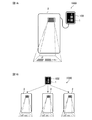
- FIG. 1A is a diagram illustrating an example of a configuration of an editing system according to the first embodiment.
- FIG. 1B is a diagram showing another example of the configuration of the editing system according to the first embodiment.
- FIG. 3 is a diagram illustrating an example of a first image displayed by a projector according to the first embodiment.
- FIG. 5 is a diagram illustrating an example of a first image to which an animation is added in the first embodiment.
- FIG. 2 is a diagram showing a configuration example of an editing device according to the first embodiment.
- FIG. 5 is a diagram for describing an example of an image editing screen that is called by a user touching a display unit in the first embodiment.
- FIG. 6 is a flowchart for explaining the operation of the editing device when the user edits the first image displayed by the projector using the editing device according to the first embodiment.
- FIG. 5 is a diagram for describing an example of information displayed in each area of the image editing screen in the first embodiment.
- FIG. 5 is a diagram for describing an example of an image selection screen in the first embodiment.
- it is a figure which shows an example of the image of the operation
- FIG. 9 is a diagram showing an image of an example of a screen on which the display control unit displays an editing component for editing the degree of animation given to the second image in the first embodiment.
- FIG. 9 is a diagram showing another example image of a screen on which the display control unit displays an editing component for editing the degree of animation given to the second image in the first embodiment.
- FIG. 7 is a diagram illustrating an example of an animation setting screen displayed in an editing function display area according to the first embodiment.
- 14A and 14B are diagrams illustrating an example of a hardware configuration of the editing device according to the first embodiment of the present invention.
- FIG. 9 is a diagram illustrating a configuration example of an editing device according to a second embodiment.
- FIG. 14 is a diagram illustrating an example of an image of an edited image display area in which information based on editing guide information is displayed by a display control unit in the second embodiment.
- FIG. 13 is a diagram illustrating another example of an image in an edited image display area in which information based on editing guide information is displayed by the display control unit in the second embodiment.
- FIG. 14 is a diagram illustrating a configuration example of an editing device according to a third embodiment.
- FIG. 14 is a diagram illustrating an example of an image in which a first image is deformed or rotated so that an output control unit is displayed in a predetermined size and orientation when viewed from a viewer in a third embodiment. It is.
- FIG. 14 is a diagram illustrating a configuration example of an editing device according to a fourth embodiment.
- the output control unit changes the luminance or the color of the first image when environmental information is not taken into consideration so that the first image is displayed with the color and shape of the second image unchanged.
- FIG. 9 is a diagram showing an example of an image displaying a first image displayed.
- the editing device is a device for the user to edit the first image displayed on the output device for the viewer to visually recognize.
- an image indicating information for controlling a human flow is assumed as the first image.
- the information indicated by the first image is, specifically, information indicating the type of indoor facility, information indicating the traveling direction, information indicating emergency evacuation guidance, information indicating no entry, or visual recognition to be controlled by human flow. And information indicating the attributes of the viewer such as the gender of the viewer.
- the first image is an image including one or more characters, one or more character strings, one or more figures, one or more symbols, one or more photos, and the like. Each of these characters, character strings, figures, symbols, photographs, and the like is hereinafter also referred to as “image component”.
- the mode of the first image may be a still image or a moving image.
- the editing device is mounted on a tablet PC (Personal Computer) (hereinafter, referred to as “tablet PC”) having a touch panel.
- the output device is a projector that projects an image on an object using light.
- the projector projects a projection image on an object.
- the projection image projected from the projector onto the object forms a first image on the surface of the object.
- the shape of the projection image is distorted depending on the shape or position of the surface of the target object.
- the projection image is generated as an image in which an appropriate first image is displayed on the object according to the shape or position of the surface of the object.
- the target object is a building floor having a projection surface on which a projection image is projected by a projector.
- the target object may be a pillar, a wall, the ground, or the like, and includes any object having a surface on which a first image can be displayed by projecting an image for projection by a projector.
- the assumed viewer is assumed to be a person around the projector.
- the user who uses the editing device 1 according to the first embodiment can use the image displayed on the display unit 101 (described later) of the editing device 1 corresponding to the first image displayed on the floor by the projector.
- second image By editing (hereinafter, referred to as “second image”) using a tablet PC, the first image displayed on the floor can be edited.
- the editing device 1 generates an output image for the output device to display the first image based on the second image edited by the user.
- the output image is provided so that when the output device outputs the output image, a desired first image is displayed so as to be visible to a viewer.
- the output device is a projector
- the editing device 1 generates a projection image to be projected by the projector as an output image.
- the editing device 1 outputs the generated projection image to the projector, and the projector projects the projection image onto the floor, thereby displaying the first image on the floor.
- a second image corresponding to the first image is displayed on the display unit provided in the tablet PC, and the user actually displays the second image on the floor.
- the user can freely edit the second image on the tablet PC while viewing the first image thus obtained, and reflect the edited contents on the first image displayed by the projector in real time.
- FIG. 1 is a diagram illustrating a configuration example of an editing system 1000 according to the first embodiment.
- FIG. 1A is a diagram illustrating an example of a configuration of an editing system 1000 according to Embodiment 1, and illustrates an example in which one tablet PC 100 and one projector 2 are communicably connected by wire.
- FIG. 1B is a diagram illustrating another example of the configuration of the editing system 1000 according to the first embodiment.
- One tablet PC 100 and a plurality of projectors 2 are selectively communicably connected to each other. An example is shown.
- the tablet PC 100 includes a display unit 101.
- the display unit 101 is a touch panel display. The user edits the second image by touching the display unit 101 with a finger, for example.
- the editing device 1 generates a projection image based on the second image edited by the user touching the display unit 101 and outputs the generated image to the projector 2, and the projector 2 projects the projection image on the floor.
- the tablet PC 100 and the projector 2 are communicably connected to each other by any means, whether wired or wireless.
- FIG. 1A shows an example in which one tablet PC 100 and one projector 2 are communicably connected by wire.
- the tablet PC 100 and the projector 2 may be connected to be wirelessly communicable using WiFi (registered trademark) communication, Bluetooth (registered trademark) communication, or the like. Further, one tablet PC 100 and a plurality of projectors 2 may be communicably connected.
- FIG. 1B shows an example in which one tablet PC 100 is selectively communicably connected to three projectors 2 by wireless.
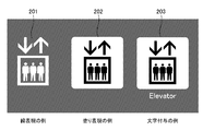
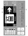
- FIG. 2 is a diagram illustrating an example of a first image displayed by projector 2 in the first embodiment.
- FIG. 2 shows an image showing an elevator as an example of the first image.
- Each of the plurality of images shown in FIG. 2 is an image showing an elevator. However, the lines and the background color are different from each other (see 201 and 202 in FIG. 2).
- This is an image in which the combination of a character and a graphic is different from each other (see 202 and 203 in FIG. 2).
- FIG. 2 illustrates an example of an image in which a graphic indicating an elevator and characters indicating the elevator are combined as image components (see 203 in FIG. 2), but the first image is, for example, a certain image.
- a combination of a figure indicating a location and a symbol such as an arrow may be used.
- FIG. 3 is a diagram illustrating an example of the first image to which an animation is added in the first embodiment.
- Examples of the animation include a slide animation, a blinking animation, and a multi-language switching animation.
- FIG. 3A shows an example of a first image in which a blinking animation is added to a figure indicating a danger signal.
- FIG. 3B illustrates an example of a first image in which a multilingual switching animation is added to a character indicating “acceptance”.
- FIG. 3C shows an example of a first image in which a slide animation is given to a figure showing an arrow.
- the image component repeats turning on and off at predetermined time intervals.
- a cycle in which the image component completes one turn-on and one turn-off per second (for example, after the image component turns on for 0.5 seconds, .5 seconds off) is set.
- the predetermined time interval may be appropriately editable by the user.
- FIG. 3A shows a state in which the image component is lit.
- the image component is switched at a predetermined time interval from an expression in one of a plurality of languages to an expression in another language.
- the predetermined time interval and the order in which the languages are switched are, for example, in an initial state, each language is sequentially displayed for 2 seconds at a time (for example, Chinese 2 seconds ⁇ Japanese 2 seconds ⁇ Korea) (In the order of 2 seconds). Further, the predetermined time interval may be appropriately editable by the user. Further, the order in which the languages are switched may be such that the user can appropriately edit.
- FIG. 3B shows an image component to which an animation capable of switching between Japanese characters and English characters has been added as the character indicating “acceptance”. The left side of FIG. 3B is an image component expressed in Japanese, and the right side is an image component expressed in English, and these image components are switched at predetermined time intervals.
- the image component moves from a predetermined start point in the area where the first image is displayed toward a predetermined end point, and moves to the end point.
- the operation is completed, the operation of moving from the start point to the end point is repeated again.
- the time interval at which the image component repeats the operation for example, as an initial state, a cycle in which one slide animation per second is completed from the beginning to the end (for example, the image component changes from the start point to the end point during one second) To move towards).
- the time interval at which the image component repeats the operation may be appropriately editable by the user.
- the image component is a figure showing an arrow, and the two arrows are shown to indicate that the arrow is moving. However, actually, the two arrows are always displayed simultaneously. It is not something to be done.
- the first image or image components of the first image may be displayed by the projector 2 in various manners.
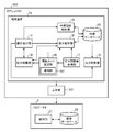
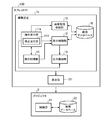
- FIG. 4 is a diagram illustrating a configuration example of the editing device 1 according to the first embodiment.
- FIG. 4 also shows a configuration example of the projector 2 communicably connected to the editing apparatus 1 according to the first embodiment.
- the editing device 1 includes an operation receiving unit 11, a display control unit 12, an image registration control unit 13, an operation restriction unit 14, an output control unit 15, and an image database 16.
- the operation receiving unit 11 receives various information corresponding to the operation based on various operations performed by the user.
- a description that “the operation receiving unit 11 receives an operation” means that the operation receiving unit 11 receives various information corresponding to the operation.
- the operation receiving unit 11 receives a call operation of the image editing screen, which is input by the user touching the display unit 101.
- the user wants to edit the first image displayed on the floor by the projector 2
- the user touches the image editing screen call button displayed on the display unit 101 to call the image editing screen. And call the image editing screen.
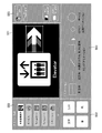
- FIG. 5 is a diagram illustrating an example of an image of an image editing screen that is called by a user touching display unit 101 in the first embodiment.
- the image editing screen has an edited image display area 501, an image list display area 502, and an edit function display area 503.
- the edited image display area 501 is an area where a second image corresponding to the first image displayed on the floor by the projector 2 is displayed.
- the image list display area 502 is an area in which various image components stored in the image database 16 are displayed in a list. For example, the user creates a plurality of types of graphics in advance as image components, and stores the graphics in the image database 16 together with a name specifying the classification for each classification of the graphics.
- the user obtains a plurality of types of photo data as image components in advance, and stores the data of the photo in the image database 16.
- the categories and names of the icon figures and the photo folders are displayed in a list based on the data stored in the image database 16.
- the editing function display area 503 is an area where various editing functions used when editing the second image are displayed.
- the various editing functions are, for example, a function for calling a character input screen or an animation setting screen for editing a second image, or a type or image of a character to be displayed. This is a function for selecting the type of animation to be given to the component.
- the image list display area 502 and the editing function display area 503 are components for editing.
- the editing parts are various parts displayed on the image editing screen in order to edit the second image displayed in the editing image display area 501.
- the editing parts are contents other than the second image corresponding to the first image among the contents displayed on the image editing screen.
- the editing parts include an image list display screen, operation buttons for specifying the degree of slide animation, a frame, a color chart, or a brightness adjustment screen, which will be described later.
- Various contents are included.
- each area shown in FIG. 5 is merely an example, and it is sufficient that at least the edited image display area 501 is provided on the image editing screen. Also, for example, when the image editing screen has an edited image display area 501, an image list display area 502, and an editing function display area 503, the edited image display area 501 is Is also desirable.
- the user calls the image editing screen as shown in FIG. 5 and edits the second image from the image editing screen to edit the first image displayed by the projector 2 in real time. Can be done with
- the operation receiving unit 11 receives a call operation of various screens input by the user by operating the display unit 101, in addition to a call operation of the image editing screen.
- the operation receiving unit 11 outputs information on the received call operation of various screens to the display control unit 12.
- the operation receiving unit 11 receives, from the user, a selection operation of each image component configuring the second image displayed on the edited image display area 501.
- the user selects an image component to be edited by touching an image component to be edited among the image components constituting the editing image displayed on the display unit 101.
- the operation receiving unit 11 receives information for specifying the image component selected by the user.
- the operation receiving unit 11 outputs information for specifying the received image component to the display control unit 12.
- the operation accepting unit 11 performs an editing operation performed on an image component selected by the user among image components constituting the second image displayed in the edited image display area 501 of the image editing screen. And outputs the edited attribute information of the image component to the display control unit 12.
- the user displays the second image in the edited image display area 501, for example, operates the display unit 101 to select a desired image component, edit the position of the image component, and edit the position of the image component. Editing the shape including the size or orientation, editing the color of the image component, editing the brightness of the image component, editing the animation given to the image component, deleting the image component, or An editing operation of an image component such as addition of an image component is performed.
- the operation receiving unit 11 receives an editing operation performed on each image component by the user.
- the operation accepting unit 11 determines, for the second image displayed in the edited image display area 501 after the user has edited each image component, the attribute of each image component constituting the second image.
- the information is output to the display control unit 12.
- the attribute information is information relating to each image component constituting the second image displayed in the edited image display area 501, and includes the position, shape, color, brightness, or assigned animation of the image component. And so on.
- the display control unit 12 controls display of various information on the display unit 101.
- the display control unit 12 causes the display unit 101 to display various screens based on the screen call operation information output from the operation reception unit 11.
- the display control unit 12 causes the display unit 101 to display the image editing screen as shown in FIG. .
- the display control unit 12 displays an editing component used when editing the second image. Details will be described later.
- the display control unit 12 may output the information to the display unit 101 based on the information output from the operation reception unit 11 for specifying the image component selected by the user and the attribute information of the image component.
- the second image is displayed on the edited image display area 501.
- the display control unit 12 outputs information of the second image displayed in the edited image display area 501 to the output control unit 15.
- the display control unit 12 includes information for specifying each image component constituting the second image displayed in the edited image display area 501, and attribute information of each image component. Is output to the output control unit 15.
- the image registration control unit 13 uses the newly created image component based on information on the image component registration operation from the operation receiving unit 11. Is added to the image database 16. Note that the editing device 1 does not necessarily have to have a function of adding a new image component to the image database 16.
- the operation restricting unit 14 restricts the operation of the operation receiving unit 11 according to the editing operation received by the operation receiving unit 11. Specifically, for example, in order to delete a certain image component in the second image, the user moves the image component from the current display position to a position outside the edit image display area 501. When an operation is performed, after the image component is moved to the end of the edited image display area 501, the operation restricting unit 14 accepts an editing operation in which the operation receiving unit 11 moves the image component further. Once, restrict it. When the user deletes an image component in the second image, the user slides the finger outside the edit image display area 501 while touching the image component displayed in the edit image display area 501 with the finger.
- the operation restricting unit 14 temporarily restricts the reception of the editing operation by the operation receiving unit 11, as described above, for the editing operation for deleting the image component, thereby deleting the image component due to the user's erroneous operation. Can be prevented. Further, for example, when the operation restriction unit 14 determines that it is difficult for the operation reception unit 11 to determine whether the user touched the display unit 101 with one finger or two points, the operation reception unit 11 11, the reception of the editing operation by the touch is canceled. Alternatively, in the same case, the operation restricting unit 14 causes the operation receiving unit 11 to receive an editing operation by the touch with the point at which the user touches the display unit 101 as one point.
- the operation receiving unit 11 determines whether it is difficult to detect a touched point based on, for example, an area where a touch is detected, and outputs a determination result to the operation limiting unit 14.
- the operation restricting unit 14 can prevent an erroneous operation of the user by restricting the reception of the editing operation as described above or by accepting the editing operation as a simpler operation.
- the operation restriction unit 14 outputs information indicating that the operation reception is restricted to the display control unit 12.
- the output control unit 15 causes the projector 2 to display the first image. Specifically, the output control unit 15 determines the first image corresponding to the second image based on the shape or position of the surface of the object on which the first image is displayed and the edited second image. Is generated on the target object so that the image of the projection image can be visually recognized by a viewer.
- the shape or position of the surface of the object on which the first image is displayed is acquired in advance, for example, when the projector 2 is installed, and stored in an appropriate storage device (not shown) to which the editing device 1 can refer. ing.
- the output control unit 15 outputs the generated projection image to the projector 2, and causes the projector 2 to execute projection of the projection image on the floor.
- each of the image components constituting the second image displayed in the edited image display area 501 And the attribute information of each image component may be output to the projector 2.
- the operation accepting unit 11 also accepts a name specifying the second image to be registered, and outputs information indicating the name to the projector 2. Is also good. It is assumed that the user can input the name by operating the display unit 101.
- the operation accepting unit 11 sets a condition for the projector 2 to start displaying the first image based on the second image (hereinafter, referred to as a “display trigger”). ) May be received, and the information indicating the display trigger may be output to the projector 2.
- a condition based on time or date For example, the display trigger is such that the projector 2 starts displaying a first image when the time reaches midnight, and causes the projector 2 to display another first image when the time reaches midnight. It can be set as a condition.
- the projector 2 when the date reaches the first date, the projector 2 starts displaying a certain first image, and when the date reaches the second date, the projector 2 starts displaying the other first image.
- the condition for displaying an image can be set.
- Another example of the display trigger is a condition based on operation information of facilities in a building.
- the in-building equipment is, for example, a security gate, an elevator, an escalator, or a station platform fence.
- the display trigger can be set as a condition that, when the security gate detects a situation having a security problem, the projector 2 starts displaying the first image by a blinking animation indicating a warning.
- the projector 2 when the elevator trigger is immediately before the elevator car arrives at the floor where the projector 2 is installed while the projector 2 is displaying the first image, the projector 2 causes the projector 2 to perform the certain first image. May be set as a condition for starting display of another first image having a different display direction from that of the first image. Further, for example, when the escalator speed is changed when the escalator decelerates or stops when there is no person around, the projector 2 causes the projector 2 to move up and down the escalator being displayed as the first image. May be set as a condition for starting the display of the first image in which the animation speed of the arrow is changed.
- the display trigger is such that the projector 2 starts displaying a first image indicating an appropriate train stop position or an appropriate station platform door opening / closing position according to the train operation information. It can be set as a condition.
- a display trigger is conditional on information from the building management system.
- the information from the building management system is, for example, information from a sensor installed in a building or information from a monitoring camera installed in a building.
- the display trigger can be set as a condition that causes the projector 2 to start displaying the first image indicating the appropriate direction of the flow of people according to the congestion state of the person detected by the building management system.
- the display trigger can be set as a condition for the projector 2 to start displaying the first image indicating the appropriate passage area division according to the attribute of the person detected by the building management system.
- a display trigger is conditional on information obtained from a personal authentication medium.
- the personal authentication medium is a smartphone, a card, or the like owned by an individual.
- the display trigger indicates a route that the projector 2 guides the user to the room according to the information. It can be set as a condition for starting the display of the first image.
- the display trigger causes the projector 2 to display the first image in which characters in a language corresponding to the nationality are shown. May be set as a condition for starting the display of.
- the display trigger is based on a condition that a distance between the projector 2 and a person to be displayed by the projector 2 is a condition.
- the display trigger causes the projector 2 to display the first image of an appropriate aspect ratio or size in accordance with the distance between the projector 2 and the person to be displayed by the projector 2.
- the condition for starting can be set.
- the control unit 21 (to be described later, hereinafter referred to as “projector control unit 21”) included in the projector 2 is configured to output the second image of the second image to be registered from the output control unit 15 for the second image to be registered.
- the information is transferred to the second image.
- the image is registered in an image database 22 (to be described later; hereinafter, referred to as a “projector-side image database 22”) of the projector 2 in association with a projection image based on the image. As shown in FIG.
- the tablet PC 100 is a part of the plurality of projectors 2. Is connected to the one or more projectors 2 to edit the first image displayed by the one or more projectors 2. In this case, the projector 2 not connected to the tablet PC 100 cannot acquire, for example, a projection image based on the edited second image from the tablet PC 100.
- various information such as the information of the second image output from the output control unit 15 is registered in the projector-side image database 22, each projector 2 is connected to the tablet PC 100. Even in the absence state, it is possible to display the first image corresponding to the second image based on various information registered in the projector-side image database 22.
- the user can connect the tablet PC 100 to the desired projector 2 so that the tablet PC 100 can communicate with the desired projector 2.
- the first image displayed by the projector 2 can be edited.
- the user connects the tablet PC 100 to be communicable with the certain projector 2 and After the image information is called, the tablet PC 100 is communicably connected to the other projector 2 to cause the other projector 2 to display the first image based on the information of the second image. You can also.
- the image database 16 stores image components.
- the image database 16 stores, for example, image components in a preset hierarchical structure for each class, and also stores the name of each class.
- the image database 16 is provided in the editing device 1.
- the present invention is not limited to this. It may be provided in a place that can be referred to.
- the projector 2 includes a projector control unit 21 and a projector-side image database 22.
- the projector control unit 21 controls all functions of the projector 2. For example, upon acquiring the projection image output from the editing device 1, the projector control unit 21 controls a projection unit (not shown) of the projector 2 to project the projection image. Further, for example, upon receiving an instruction including the name of the second image input by the user using the operation unit (not shown), the projector control unit 21 reads the name of the second image from the projector-side image database 22. The projection image associated with is acquired, and the above-described projection unit is controlled to project the projection image.
- the projector control unit 21 receives, from the output control unit 15, information for specifying image components constituting the second image to be registered, attribute information of each image component, and information indicating the name of the second image.
- the information is registered in the projector-side image database 22 in association with the projection image based on the second image.
- the projector-side image database 22 includes information for specifying image components constituting the second image to be registered, attribute information of each image component, information indicating the name of the second image, information indicating a display trigger, or , A projection image based on the second image.
- the first image is an image in which a graphic indicating a toilet and a graphic indicating an arrow are combined as image components.
- FIG. 6 is a flowchart for explaining an operation when the user edits the first image displayed by projector 2 using editing apparatus 1 according to the first embodiment.
- Operation accepting unit 11 accepts a call operation of the image editing screen (step ST601). Specifically, the user touches the display unit 101 with a finger, for example, and performs a call operation of the image editing screen. That is, the call operation of the image editing screen is an editing start instruction for starting the editing of the first image displayed on the floor by the projector 2.
- the operation receiving unit 11 receives a call operation input by the user.
- the operation receiving unit 11 outputs information of the received call operation of the image editing screen to the display control unit 12.
- the display control unit 12 causes the display unit 101 to display an image editing screen (step ST602).
- the editing apparatus 1 performs an editing process of editing the second image based on the operation of the display unit 101 by the user (step ST603).
- step ST603 (1) Addition of Image Component
- the user operates the display unit 101 to cause the projector 2 to display the first image. That is, the editing device 1 causes the projector to display the first image based on the operation of the display unit 101 by the user.
- the editing process specifically, the user edits the second image on the image editing screen by touching the display unit 101 or the like, and the editing apparatus 1 causes the projector 2 to edit the second image.
- the display of the first image corresponding to the image is executed. The details will be described below.
- the user edits a blank second image having no image components, and displays a figure indicating a toilet (hereinafter, referred to as a “toilet icon”) and a figure indicating an arrow (
- a new second image is created in combination with the “arrow graphic”, and the projector 2 executes the display of the first image corresponding to the second image.
- the operation receiving unit 11 receives selection of an image component, and the display control unit 12 causes the edited image display area 501 to display the received image component.
- the user touches the display unit 101 with a finger, for example, and selects an image component for forming a first image to be displayed on the projector 2.
- the user performs an operation of adding an image component by touching an “add” button (not shown) displayed on the image editing screen.
- the operation receiving unit 11 receives an image component adding operation, and outputs information on the received image component adding operation to the display control unit 12.
- the display control unit 12 causes the image list display area 502 of the image editing screen to display the image components included in each classification based on the hierarchy of a plurality of types of image components stored in the image database 16 (FIG. 7 701).
- the user checks the displayed image list display area 502 and touches a desired category with a finger to select a category including the toilet icon.
- the operation receiving unit 11 receives a selection operation of the classification and outputs information for specifying the received classification to the display control unit 12.
- the display control unit 12 superimposes an image list display screen (see 702 in FIG. 7) on which a list of image components included in the classification output from the operation receiving unit 11 is displayed on the image editing screen.
- the user touches and selects the toilet icon from the displayed list of image components with a finger, slides the touched finger, and moves the toilet icon to the edited image display area 501.
- the operation receiving unit 11 receives a slide operation for moving the toilet icon by the user, and the display control unit 12 displays the toilet icon in the edited image display area 501 according to the slide operation (see 703 in FIG. 7). Further, the user selects an arrow graphic by touching an “arrow” button (see 704 in FIG. 7) displayed in the editing function display area 503.
- the operation accepting unit 11 accepts the selection of the arrow graphic, and the display control unit 12 displays the arrow graphic in the edited image display area 501 (see 705 in FIG. 7).
- the display control unit 12 displays an arrow graphic at an appropriate position in the edited image display area 501, for example. Specifically, for example, the user touches the arrow graphic and slides the touched finger to an arbitrary position in the edited image display area 501.
- the operation receiving unit 11 receives the slide operation and outputs the received slide operation to the display control unit 12.
- the display control unit 12 displays an arrow graphic at the position where the user has finished the slide operation in the edited image display area 501 (see 705 in FIG. 7).
- the arrow graphic is an arrow graphic with a slide animation.
- the operation buttons for specifying the image list display screen and the degree of the slide animation, which are displayed on the image editing screen are editing components. As described above, the user adds an image component to the second image and causes the second image to be displayed in the edited image display area 501.
- the user may input a call instruction of the image selection screen as shown in FIG. 8 from the image editing screen, and may switch to the image selection screen to display.
- the user performs a call operation of the image selection screen by touching an image selection screen call instruction (not shown) displayed on the image editing screen.
- the operation receiving unit 11 receives a call operation of the image selection screen, and the display control unit 12 switches the display to the image selection screen.
- On the image selection screen an image configured by a combination of image components set in advance is displayed.
- These preset images are stored in, for example, the image database 16. Specifically, for example, as shown in FIG. 8, an image in which a toilet icon and an arrow graphic are combined is displayed.
- the user touches and selects a desired image (here, an image in which the toilet icon and the arrow graphic are combined) from the image selection screen, and the operation reception unit 11 receives the selected image. Then, the display control unit 12 displays the selected image as a second image at an appropriate position in the edited image display area 501 of the image editing screen. At this time, the display control unit 12 switches from the image selection screen to the image editing screen again. As described above, the user can also select an existing second image from the image selection screen and display it on the edited image display area 501.
- a desired image here, an image in which the toilet icon and the arrow graphic are combined
- the user can freely create an image component and add it to the second image by tracing the edited image display area 501 with a finger. Specifically, the user traces the edited image display area 501 with a finger to draw an image component including a toilet icon and an arrow graphic.
- the image component is a graphic, but the image component is a character string, and the user can input the image component as a character string by, for example, a keyboard operation or a voice input operation.
- the user performs a keyboard screen calling operation, and the display control unit 12 causes the keyboard screen to be displayed. The user touches the keyboard screen to input a character string, and the operation receiving unit 11 receives the input character string.
- the maximum number of characters that can be input may be set in advance.
- the editing device 1 is provided with a translation unit (not shown) having a translation function corresponding to multiple languages, the translation unit translates the input character string into another language, and the display control unit 12 The displayed character string may be added to the edited image display area 501 and displayed.
- the user can create an image component composed of a character string based on audio information by inputting audio into a microphone (not shown) provided in the editing device 1.
- the translation unit translates audio information based on the input audio into another language
- the display control unit 12 adds a character string based on the translated audio information to the edited image display area 501 and displays the edited image. You may do so.
- the user can add an image component created by an appropriate method to the second image.
- the user can also register the newly created image component in the image database 16. Specifically, the user performs a registration operation by touching a “register” button (not shown) displayed on the image editing screen.
- the operation receiving unit 11 receives a registration operation and outputs the registration operation to the image registration control unit 13.
- the image registration control unit 13 registers an image component newly added to the edited image display area 501 in the image database 16.
- the image registration control unit 13 adds the classification to the input component when adding the image component.
- the image component is added.
- a character string input from a keyboard or a character string based on audio information is translated to create an image component, the user uses the character string before translation as an image component in the image database 16. Can also be registered.
- the display control unit 12 outputs information of the second image displayed in the edited image display area 501 to the output control unit 15.
- the output control unit 15 is configured to project the first image corresponding to the second image based on the second image output from the display control unit 12 such that the first image is displayed on a target object so as to be visible to a viewer. Generate an image for use.
- the output control unit 15 outputs the generated projection image to the projector 2, and causes the projector 2 to execute projection of the projection image on the floor.
- the projector 2 projects the projection image on the floor, a first image having the same shape as the second image and visible to the viewer is displayed on the floor.
- the output control unit 15 generates the projection image, the editing component displayed on the image editing screen is not used.
- the output control unit 15 causes the projector 2 to execute the display of the first image
- the editing component displayed on the image editing screen is not displayed. That is, the image list display screen and the like are not displayed on the floor.
- the first image is displayed on the target object by the projector 2 based on the second image edited on the tablet PC 100 by the user.
- the user further operates the second image displayed in the edited image display area 501 of the image editing screen. Edit the image as appropriate. Specifically, the user touches the image editing screen, selects one of the image components constituting the second image, and edits the image component.
- the operation accepting unit 11 accepts the selection of the image component and the editing operation of the selected image component, and outputs the edited attribute information of the image component to the display control unit 12, and the display control unit 12
- the second image composed of the edited image components is displayed in the edited image display area 501.
- the display control unit 12 displays the editing component so as to be superimposed on the image component.
- the display control unit 12 displays the second image in the edited image display area 501 and outputs information on the second image to the output control unit 15.
- the output control unit 15 generates a projection image based on the second image, outputs the generated projection image to the projector 2, and causes the projector 2 to execute projection of the projection image on the floor.
- the editing content specified by the user is reflected on the first image displayed on the object by the projector 2.
- the editing apparatus 1 when the user operates the display unit 101 to start editing the second image, the editing apparatus 1 causes the projector 2 to display the first image based on the edited second image at any time. to continue.
- the user edits the shape including the size or orientation of each image component constituting the second image displayed in the edited image display area 501 of the image editing screen. can do.
- the user edits the image components constituting the second image on the image editing screen, and reflects the edited contents on the first image.
- the user touches and selects an image component to be edited among image components constituting the second image displayed in the edited image display area 501.
- the user selects the toilet icon from the toilet icon and the arrow graphic.
- the user selects an image component by, for example, touching the vicinity of the center of the image component with one finger.
- the vicinity of the center of the image component means, for example, within a range of approximately 50% of the area of the entire image component, including the center point of the image component.
- the vicinity of the center of the image component may be set to be circular from the center point of the image component.
- the editing device 1 allows the user to touch the image component with one finger near the center of the image component, and touch the edge of the image component with another finger, for example. It may be configured to be selectable.
- the operation receiving unit 11 receives the selection of the image component, and outputs information for specifying the selected image component to the display control unit 12.
- the display control unit 12 displays a frame around the selected image component.
- the frame is a component for editing.
- the display control unit 12 displays the image component and the frame in a superimposed manner. For example, assuming that the operation receiving unit 11 receives the selection of the toilet icon, the display control unit 12 superimposes and displays a frame around the toilet icon. By displaying the frame by the display control unit 12, the user can instantly grasp which image component is to be edited without staring at the display.
- FIG. 9 is a diagram illustrating an example of an image of an operation of editing the size of an image component by touching with two fingers by the user in the first embodiment.
- a frame 901 indicating that an image component is selected is shown.
- the operation accepting unit 11 outputs the attribute information of the image component whose size has been edited to the display control unit 12.
- the display control unit 12 increases or decreases the size of the image component displayed in the edited image display area 501 based on the attribute information, and edits the size of the image component after editing the size of the image component.
- the information of the second image is output to the output control unit 15.
- the output control unit 15 causes the projector 2 to display the first image based on the information of the edited second image output from the display control unit 12. However, the output control unit 15 does not project the editing component. That is, the frame 901 is not projected. Thereby, the first image displayed on the target object by the projector 2 is edited in real time. In addition, the editing component that is not necessary for a viewer who views the first image and a user who is editing while viewing the first image is not displayed by the projector 2, so that the viewer or the like can view the first component. Can be prevented from being difficult to see.
- FIG. 10 is a diagram illustrating an example of an image of an operation in which a user slides one finger to edit the orientation of an image component in the first embodiment.
- a frame 1001 indicating that an image component is selected is shown by 1001.
- the operation receiving unit 11 outputs to the display control unit 12 the attribute information of the image component edited by the slid finger.
- the display control unit 12 changes the direction of the image component displayed in the edited image display area 501 based on the attribute information, and outputs the information of the second image after the direction of the image component is changed. Output to the control unit 15.
- the output control unit 15 causes the projector 2 to display the first image based on the information of the edited second image output from the display control unit 12. However, the output control unit 15 does not display the editing component. That is, the frame 1001 is not displayed. Thereby, the first image displayed on the target object by the projector 2 is edited in real time. In addition, the editing component that is not necessary for a viewer who views the first image and a user who is editing while viewing the first image is not displayed by the projector 2, so that the viewer or the like can view the first component. Can be prevented from being difficult to see.
- the user can also edit the color of the second image displayed in the edited image display area 501 of the image editing screen.
- the user edits the second image to reflect the edited content on the first image.
- the color to be edited includes, for example, the color of each image component constituting the second image or the color of the background of the second image.
- a predetermined color is set as an initial value for each image component constituting the second image.
- the background of the image component or the background of the second image is set to be displayed in black as an initial value (see FIG. 5).
- the initial value of the background color in the first graphic displayed by the projector 2 is, for example, transparent.
- the user first touches and selects an image component.
- the specific operation is the same as the specific operation described in “(2) Editing the shape of the image component”, and thus the duplicated description will be omitted.
- the user edits the color of the image component. Specifically, the user touches a “color” button (see FIG. 5) displayed in the editing function display area 503 with a finger, for example, to display a color chart as an editing component. I do.
- the operation receiving unit 11 receives a color chart display operation and outputs the operation to the display control unit 12.
- the display controller 12 superimposes and displays the color chart on the image editing screen.
- the user touches a desired color on the color chart superimposed on the image editing screen to change the color of the selected image component.
- the operation receiving unit 11 receives the attribute information of the image component after the color has been changed, and outputs the attribute information to the display control unit 12.
- the display control unit 12 changes the color of the image component displayed in the edited image display area 501 based on the attribute information, and outputs the information of the second image after the color of the image component is changed. Output to the control unit 15.
- the output control unit 15 causes the projector 2 to display the first image based on the information of the edited second image output from the display control unit 12. However, the output control unit 15 does not display the editing component. That is, the color chart is not displayed. Thereby, the first image displayed on the target object by the projector 2 is edited in real time. In addition, the editing component that is not necessary for a viewer who views the first image and a user who is editing while viewing the first image is not displayed by the projector 2, so that the viewer or the like can view the first component. Can be prevented from being difficult to see.
- the user can also edit the luminance of the second image displayed in the edited image display area 501 of the image editing screen.
- the user edits the second image to reflect the edited content on the first image.
- the user first touches and selects an image component.
- the specific operation is the same as the specific operation described in “(2) Editing the shape of the image component”, and thus the duplicated description will be omitted.
- the user can edit the luminance of the entire second image, and can also edit the luminance of a part of the second image.
- the user traces, for example, a part whose luminance is to be edited with a finger.
- the operation receiving unit 11 receives information of a part traced by the user's finger and outputs the information to the display control unit 12.
- the display control unit 12 displays, for example, a frame surrounding a part traced by the user's finger.
- the user edits the brightness of the image component. Specifically, the user touches a “brightness” button (not shown) displayed in the editing function display area 503 with a finger, for example, to display a brightness adjustment screen as an editing component. Perform the operation.
- the operation receiving unit 11 receives a brightness adjustment screen display operation and outputs the operation to the display control unit 12.
- the display control unit 12 superimposes the brightness adjustment screen on the image editing screen.
- the user touches a desired luminance on the luminance adjustment screen superimposed on the image editing screen to change the luminance of the selected image component.
- the operation receiving unit 11 receives the attribute information of the image component after the luminance is changed, and outputs the attribute information to the display control unit 12.
- the display control unit 12 changes the luminance of the image component displayed in the edited image display area 501 based on the attribute information, and outputs the information of the second image after the luminance of the image component is changed. Output to the control unit 15.
- the output control unit 15 causes the projector 2 to display the first image based on the information of the edited second image output from the display control unit 12.
- the output control unit 15 does not display the editing component. That is, the brightness adjustment screen is not displayed.
- the first image displayed on the target object by the projector 2 is edited in real time.
- the editing component that is not necessary for a viewer who views the first image and a user who is editing while viewing the first image is not displayed by the projector 2, so that the viewer or the like can view the first component. Can be prevented from being difficult to see.
- the user edits the animation assigned to the second image displayed on the edited image display area 501 of the image editing screen. Can also be performed.
- the user edits the second image to reflect the edited content on the first image.
- the user first touches and selects an image component.
- the specific operation is the same as the specific operation described in “(2) Editing the shape of the image component”, and thus the duplicated description will be omitted.
- the display control unit 12 performs the editing for editing the degree of animation in addition to the operation described in “(2) Editing the shape of the image component”. Display parts.
- the display image of the image component in which the display control unit 12 displays the editing component indicating the degree of animation will be described with some examples. In the drawings showing the following display images, only the second image is shown for simplicity of explanation. Actually, the second image shown in the drawing is displayed in the edited image display area 501 of the image editing screen.
- FIG. 11 is a diagram showing an example of a screen in which the display control unit 12 displays an editing component for editing the degree of animation given to the image component in the first embodiment.
- the image components are image components indicating arrows.
- Reference numeral 1103 in FIG. 11 denotes a frame indicating that an image component has been selected.
- the animation is a slide animation
- the display control unit 12 displays an editing component for editing the degree of the slide animation.
- the display control unit 12 displays an editing component 1101 for editing the moving distance of the slide animation and an editing component 1102 for editing the moving speed of the slide animation.
- the user can increase the moving distance of the slide animation by increasing the width of the editing component 1101, and can shorten the moving distance of the slide animation by reducing the width of the editing component 1101. Further, the user can increase the moving speed of the slide animation by increasing the length of the editing component 1102, and can decrease the moving speed of the slide animation by shortening the editing component 1102.
- FIG. 12 is a diagram showing an image of another example of a screen in which the display control unit 12 displays an editing component for editing the degree of animation given to the image component in the first embodiment. .
- the image component is a figure indicating a danger signal.
- Reference numeral 1207 in FIG. 12 denotes a frame indicating that an image component is selected.
- the animation is a blinking animation
- the display control unit 12 displays an editing component for editing the degree of the blinking animation.
- the display control unit 12 includes a first circle 1201, a second circle 1202, a third circle 1203, and a fourth circle 1203 as editing parts for editing the degree of blinking of the blinking animation.
- a circle 1204 is displayed.
- the user can increase the size of the first circle 1201 to increase the light-off time of the blinking animation, and reduce the size of the first circle 1201 to reduce the light-off time of the blinking animation. can do. Further, the user can increase the fade time at the time of turning off the blinking animation by increasing the width 1205 of the first circle 1201 and the second circle 1202, and can reduce the fade time at the time of turning off the blinking animation by decreasing the width 1205. The fade time can be shortened. Further, the user can increase the size of the fourth circle 1204 to increase the lighting time of the blinking animation, and reduce the size of the fourth circle 1204 to increase the lighting time of the blinking animation. Can be shortened.
- the user can increase the fade time when the blinking animation is turned on by increasing the width 1206 of the third circle 1203 and the fourth circle 1204, and can reduce the width of the blinking animation when the blinking animation is turned on by decreasing the width 1206.
- the fade time can be shortened.
- the user edits the animation given to the image component. Specifically, for example, the user touches both ends of the editing component 1102 for editing the moving speed of the slide animation with two fingers, and spreads the two fingers to move the slide animation. Increase speed. Also, for example, the user increases the size of the first circle 1201 for editing the blinking animation, thereby increasing the light-off time of the blinking animation.
- the operation receiving unit 11 receives the attribute information of the image component after the assigned animation has been changed, and outputs the attribute information to the display control unit 12.
- the display control unit 12 changes the animation assigned to the image component displayed in the edited image display area 501 based on the attribute information, and changes the animation assigned to the image component.
- the information of the second image is output to the output control unit 15.
- the output control unit 15 causes the projector 2 to display the first graphic based on the information of the edited second image output from the display control unit 12.
- the output control unit 15 does not display the editing component. That is, the editing parts 1101 and 1102, the first circle 1201, the second circle 1202, the third circle 1203, and the fourth circle 1204 are not displayed. Thereby, the first image displayed on the target object by the projector 2 is edited in real time.
- the editing component which is not necessary for the viewer who views the first graphic and the user who is editing while viewing the first image, is not displayed by the projector 2, the viewer or the like can view the first component. Can be prevented from being difficult to see.
- the present invention is not limited to this, and the user can add a new animation to the image component.
- the user touches a desired animation on the animation setting screen (for example, see 1301 in FIG. 13) displayed in the editing function display area 503 to edit the animation.
- the operation receiving unit 11 receives the attribute information of the image component after the animation has been given, and outputs the attribute information to the display control unit 12.
- the display control unit 12 applies an animation to the image component displayed in the edited image display area 501 based on the attribute information, and outputs information of the second image after the animation is applied to the image component. Output to the control unit 15.
- the output control unit 15 causes the projector 2 to display the first graphic based on the information of the edited second image output from the display control unit 12. However, the output control unit 15 does not display the editing component. That is, for example, the editing parts 1101 and 1102 are not displayed.
- the user can also perform editing to delete the second image displayed in the edited image display area 501 of the image editing screen.
- the user edits the second image to reflect the edited content on the first image.
- the user first touches and selects an image component.
- the specific operation is the same as the specific operation described in “(2) Editing the shape of the image component”, and thus the duplicated description will be omitted.
- the user selects an image component, the user performs editing to delete the image component. Specifically, for example, the user slides a finger touching an image component, and moves the image component from the current display position to a position outside the edited image display area 501.
- the operation accepting unit 11 accepts an editing operation of moving an image component from the current display position to a position outside the edited image display area 501, and outputs the editing operation to the display control unit 12.
- the display control unit 12 deletes the image component from the image editing screen and outputs to the output control unit 15 the information of the second image after deleting the image component.
- the output control unit 15 causes the projector 2 to display the first image based on the information of the edited second image output from the display control unit 12. However, the output control unit 15 does not display the editing component. Thereby, the first image displayed on the target object by the projector 2 is edited in real time.
- the editing component that is not necessary for a viewer who views the first image and a user who is editing while viewing the first image is not displayed by the projector 2, so that the viewer or the like can view the first component. Can be prevented from being difficult to see.
- the display control unit 12 When deleting the image component from the image editing screen, the display control unit 12 causes the list display screen (see FIG. 7) of the classification to which the image component belongs to be superimposed and displayed on the image editing screen. You can also. For example, if the user accidentally deletes an image component from the image editing screen, the user again touches and selects the image component from the image editing screen and slides it to the edited image display area 501.
- the operation receiving unit 11 receives an editing operation of sliding an image component to the edited image display area 501, and the display control unit 12 displays the image component again in the edited image display area 501, and The information of the second graphic after editing the element is output to the output control unit 15.
- the output control unit 15 causes the projector 2 to display the first image based on the information of the edited second image output from the display control unit 12. In this way, even if the user accidentally deletes an image component from the image editing screen, the image component is quickly displayed again, and the information of the edited second image is displayed from the projector 2. May be displayed.
- the editing device 1 edits the first image displayed by the projector 2 in real time based on a user operation.
- the editing device 1 causes the display unit 101 to display an editing component for editing the second image so as to be superimposed on the second image.
- the editing component is not displayed. The user can edit the first image displayed on the floor in real time while keeping the first image easy to see.
- the operation restricting unit 14 appropriately responds to the operation received by the operation receiving unit 11. 11 is to be restricted.
- FIGS. 14A and 14B are diagrams illustrating an example of a hardware configuration of the editing device 1 according to the first embodiment of the present invention.
- the functions of the operation reception unit 11, the display control unit 12, the image registration control unit 13, the operation restriction unit 14, and the output control unit 15 are realized by the processing circuit 1401. That is, the editing apparatus 1 includes a processing circuit 1401 for performing control for editing the first graphic displayed by the projector 2.
- the processing circuit 1401 may be dedicated hardware as shown in FIG. 14A, or may be a CPU (Central Processing Unit) 1405 that executes a program stored in the memory 1406 as shown in FIG. 14B.
- CPU Central Processing Unit
- the processing circuit 1401 includes, for example, a single circuit, a composite circuit, a programmed processor, a parallel programmed processor, an ASIC (Application Specific Integrated Circuit), and an FPGA (Field-Programmable). Gate @ Array) or a combination thereof.
- the functions of the operation reception unit 11, the display control unit 12, the image registration control unit 13, the operation restriction unit 14, and the output control unit 15 are software, firmware, or software and firmware. This is realized by a combination of That is, the operation reception unit 11, the display control unit 12, the image registration control unit 13, the operation restriction unit 14, and the output control unit 15 execute the programs stored in the HDD (Hard ⁇ Disk ⁇ Drive) 1402, the memory 1406, and the like.
- the CPU 1405 to be executed is realized by a processing circuit such as a system LSI (Large-Scale Integration).
- the programs stored in the HDD 1402, the memory 1406, and the like are provided with a procedure or a method of the operation receiving unit 11, the display control unit 12, the image registration control unit 13, the operation restriction unit 14, and the output control unit 15 to the computer. It can also be said to be executed.
- the memory 1406 is, for example, a RAM (Random Access Memory), a ROM (Read Only Memory), a flash memory, an EPROM (Erasable Programmable Read Memory), an EEPROM (Electrical Memory, etc.).
- a volatile or volatile semiconductor memory, a magnetic disk, a flexible disk, an optical disk, a compact disk, a mini disk, a DVD (Digital Versatile Disc), and the like are applicable.
- the functions of the operation reception unit 11, the display control unit 12, the image registration control unit 13, the operation restriction unit 14, and the output control unit 15 are partially implemented by dedicated hardware, and partially implemented by software. Alternatively, it may be realized by firmware.
- the function of the operation reception unit 11 is realized by a processing circuit 1401 as dedicated hardware, and the processing of the display control unit 12, the image registration control unit 13, the operation restriction unit 14, and the output control unit 15 is performed.
- the function can be realized by a circuit reading and executing a program stored in the memory 1406.
- the image database 16 uses the HDD 1402, for example. Note that this is only an example, and the image database 16 may be configured by a DVD, a memory 1406, or the like.
- the editing device 1 has an input interface device 1403 and an output interface device 1404 for communicating with an external device such as the projector 2.
- the editing device 1 edits the first image while the output device (projector 2) is displaying the first image. And a display control unit 12 for displaying a second image corresponding to the first image and an editing component for editing the second image on an image editing screen.
- An output control unit 15 that generates an output image for displaying the first image based on the second image edited using the displayed editing component, and outputs the output image to the output device. . Therefore, the image can be edited in real time while the image is displayed by the output device. Further, the editing device 1 displays the second image and the editing component on the image editing screen.
- the editing apparatus 1 when the output control unit 15 generates an output image, the editing component displayed on the image editing screen is not used.
- the output control unit 15 causes the projector 2 to execute the display of the first image
- the editing component displayed on the image editing screen is not displayed.
- the editing component that is unnecessary for the viewer who views the first image and the user who is editing while viewing the first image is not displayed by the projector 2, so that the viewer or the like can view the first component. This makes it possible to prevent one image from being difficult to see.
- Embodiment 2 FIG.
- the second image when the editing apparatus 1 displays the second image in the edited image display area 501 of the image editing screen, the second image has a predetermined color.
- the background of the second image is basically set to an initial value such as black.
- the editing apparatus 1 performs display in consideration of information on the real space in which the first image is displayed when displaying the second image in the edited image display area 501. I do.
- the editing system 1000a is configured by adding real space information to the editing system 1000 described with reference to FIG.
- the only difference is that an acquisition device (not shown) is provided.
- the real space information acquisition device is, for example, a camera or a laser lidar.
- the real space information acquisition device acquires information about a real space in which the projector 2 is displaying the first image (hereinafter, referred to as “spatial information”). Specifically, when the real space information acquisition device is a camera, the camera photographs the projection surface on which the first image is displayed by the projector 2 and acquires the photographed image as spatial information.
- the laser rider acquires, as spatial information, information on the presence or absence of an obstacle on the projection surface on which the projector 2 displays the first image.
- the real space information acquisition device may be provided in the projector 2, for example, or may be installed on a vertical ceiling or the like of a projection surface on which the first image is displayed.
- the real space information acquisition device is installed on a vertical ceiling of a projection surface on which projector 1 displays a first image.
- the editing device 1a acquires spatial information from the real space information acquiring device, creates editing guide information based on the spatial information, and displays the editing guide information when displaying the second image. 501 is displayed.
- the editing guide information is information on a structure existing in the real space, such as the center of the floor, the center line of the passage, or an obstacle, and is information that is a target when the user edits the second image. is there.
- the display of the editing guide information allows the user to edit the second image on the image editing screen with a feeling closer to the real space in which the first image is displayed.
- FIG. 15 is a diagram illustrating a configuration example of an editing device 1a according to the second embodiment. 15, the same components as those of the editing apparatus 1 described in Embodiment 1 with reference to FIG. 4 are denoted by the same reference numerals, and redundant description will be omitted.
- the editing apparatus 1a illustrated in FIG. 15 differs from the editing apparatus 1 described with reference to FIG. 4 in that the editing apparatus 1a includes a real space information acquisition unit 17 and an editing guide setting unit 18.
- the editing guide setting unit 18 includes a notification unit 181.
- the real space information acquisition unit 17 acquires space information from the real space information acquisition device.
- the real space information acquisition unit 17 outputs the acquired space information to the editing guide setting unit 18. Further, when an image of the projection surface captured by the camera is acquired as spatial information, the real space information acquiring unit 17 outputs the image to the display control unit 12.
- the editing guide setting unit 18 sets the editing guide information based on the space information output from the real space information obtaining unit 17.
- the editing guide information includes, for example, information on the material of the projection surface of the object on which the projector 2 displays the first image, the color of the projection surface, the inclination of the projection surface, or an obstacle or a wall present on the projection surface. included.
- the editing guide setting unit 18 determines the material of the projection surface of the object on which the projector 2 displays the first image, the color of the projection surface, the inclination of the projection surface, or the obstacle or the obstacle existing on the projection surface. Detects a wall and sets editing guide information.
- the editing guide setting unit 18 may detect the above-described material and the like of the projection surface using the existing image processing technology or the like.
- the editing guide setting unit 18 outputs the set editing guide information to the display control unit 12 and the operation restriction unit 14.
- the display control unit 12 displays information based on the editing guide information output from the editing guide setting unit 18 together with the second image. . Details will be described later.
- the operation restricting unit 14 causes the operation receiving unit 11 to restrict the operation of receiving the editing operation of the second image based on the editing guide information output from the editing guide setting unit 18. Details will be described later.
- the notifying unit 181 of the editing guide setting unit 18 causes the operation receiving unit 11 to output feedback on the operation of receiving the editing operation based on the editing guide information. Details will be described later.
- the hardware configuration of the editing device 1a according to the second embodiment is the same as the hardware configuration of the editing device 1 described in the first embodiment with reference to FIGS. 14A and 14B, and therefore, a duplicated description will be omitted. I do.
- the real space information acquisition unit 17 and the editing guide setting unit 18 have the same hardware configuration as the operation reception unit 11, the display control unit 12, the image registration control unit 13, the operation restriction unit 14, and the output control unit 15.
- the operation of the editing device 1a according to the second embodiment will be described.
- the operation of the editing device 1a according to the second embodiment is basically the same as the operation of the editing device 1 described in the first embodiment using the flowchart of FIG.
- the editing apparatus 1a according to the second embodiment when displaying the image editing screen, information based on the editing guide information is displayed in the edited image display area 501. Different from 1.
- the operation of the editing device 1a only operations different from those of the editing device 1 according to the first embodiment will be described, and redundant description of the same operations as those of the editing device 1 according to the first embodiment will be omitted.
- display control unit 12 When operation accepting unit 11 accepts a call operation of the image editing screen (see step ST601 in FIG. 6), display control unit 12 causes display unit 101 to display the image editing screen (step in FIG. 6). ST602, see step ST603).
- the display control unit 12 displays information based on the editing guide information output from the editing guide setting unit 18 in the edited image display area 501 of the image editing screen.
- the display control unit 12 displays information based on the editing guide information in the editing image display area 501 a specific example.
- the display control unit 12 displays the second image in the edited image display area 501 and, for example, displays information indicating that an obstacle is present based on the editing guide information.
- the editing guide setting unit 18 outputs information indicating that there is an obstacle to the display control unit 12 as editing guide information.
- the information indicating that there is an obstacle includes the shape of the obstacle, information indicating the distance from the displayed first image to the obstacle, and the like.
- the display control unit 12 displays information indicating that an obstacle exists in the edited image display area 501 based on the editing guide information output from the editing guide setting unit 18.
- 16 is a diagram illustrating an example of an image of the edited image display area 501 in which the display control unit 12 displays information based on the editing guide information in the second embodiment. As indicated by 1601 in FIG. 16, the display control unit 12 displays information on an obstacle in the edited image display area 501.
- the operation restricting unit 14 determines, based on the editing guide information, a position where the image component and the obstacle overlap each other.
- the operation accepting unit 11 is restricted so as not to accept an editing operation for moving the image component in a direction such that the image component and the obstacle are further overlapped. I do.
- the user cannot move the image component in the direction in which the image component and the obstacle further overlap on the edited image display area 501.
- the notification unit 181 of the editing guide setting unit 18 performs feedback to the user, such as vibrating the tablet PC 100, so that the image component and the obstacle overlap. You may be notified that the image components cannot be moved in the direction in which they overlap.
- the user recognizes that the image component and the obstacle overlap on the edited image display area 501 due to the vibration of the tablet PC 100. That is, the user recognizes that the first image overlaps the obstacle on the floor.
- the display control unit 12 displays the second image in the edited image display area 501 and indicates the center of the space based on the editing guide information.
- Information can be displayed.
- the display control unit 12 can display information indicating a centerline of the passage.
- the editing guide setting unit 18 detects the center line of the passage. The information on the center line of the passage is stored in advance in a storage device (not shown) that can be referred to by the editing guide setting unit 18.
- the editing guide setting unit 18 detects the center line of the passage based on the information on the center line of the passage stored in advance and the space information output from the real space information acquisition unit 17, and converts the information on the center line.
- the information is output to the display control unit 12 as editing guide information.
- the editing guide information includes information on a positional relationship between the center line and the first image.
- the display control unit 12 displays information indicating the center line of the passage based on the editing guide information output from the editing guide setting unit 18 (1602 in FIG. 16).
- the user positions the image component so that the image component forming the second image is located at a position that is easily visible to a viewer with reference to the center line of the passage displayed in the edited image display area 501.
- Edit Specifically, in the edited image display area 501, the user touches the image component with a finger, and slides the image component to an appropriate position while using the display indicating the center line of the passage as a guide. Since the center line of the passage is displayed, the user can easily understand the position where the image component should be arranged in the edited image display area 501.
- the display control unit 12 outputs information of the second image after the image component is moved to the output control unit 15, and the output control unit 15 sends the first image information to the projector 2 based on the second image. Execute the display of the image. As a result, the user can easily display the first image at a position that is easy for the viewer to visually recognize based on the center line of the passage.
- the notifying unit 181 of the editing guide setting unit 18 determines that the image component is appropriate based on the center line of the passage based on the editing guide information.
- the notification unit 181 of the editing guide setting unit 18 provides feedback to the user, such as vibrating the tablet PC 100 or slightly moving an image component by an operation of being sucked into an appropriate position. By doing so, it is notified that the image component has been moved to an appropriate position based on the center line.
- the user recognizes that the image component has been moved to an appropriate position on the edited image display area 501 by vibrating the tablet PC 100 or the like.
- the operation restricting unit 14 may restrict the operation receiving unit 11 from receiving an editing operation for moving the image component from a current appropriate position. Note that an appropriate position based on the center line is determined in advance, and information on the appropriate position is stored in a storage device (not shown) to which the editing guide setting unit 18 can refer.
- the display control unit 12 can display the second image in the edited image display area 501 and display information indicating a material or a color of the projection surface based on the editing guide information.
- the editing guide setting unit 18 detects a material or a color of the projection surface based on the spatial information output from the real space information acquiring unit 17 and uses information on the material or the color as the editing guide information as the display control unit 12.
- Output to The material of the projection surface is, for example, wood, carpet, tile, or the like.
- the display control unit 12 displays information indicating the material or color of the projection surface based on the editing guide information output from the editing guide setting unit 18.
- FIG. 17 is a diagram showing another example of the image of the edited image display area 501 in which information based on the editing guide information is displayed by the display control unit 12 in the second embodiment. As indicated by 1701 in FIG. 17, the display control unit 12 superimposes and displays a pattern simulating the unevenness of the carpet surface on the second image.
- the editing guide setting unit 18 sets information indicating the material in the editing guide information according to the material of the projection surface, and the display control unit 12 performs the projection based on the editing guide information.
- a pattern simulating the surface material can be displayed.
- the display control unit 12 determines the background of the second image to be displayed in the editing image display area 501 based on the editing guide information. Can be changed.
- the operation restricting unit 14 Control can be performed so as to limit the accepting operation of the editing operation for editing the color or luminance of the image component.
- the editing guide information is information indicating that the projection surface is a black carpet
- the operation restricting unit 14 instructs the operation receiving unit 11 to set the image component forming the second image to red. Restrict to not accept editing operations.
- the editing guide information is information indicating that the projection surface is a black carpet
- the operation restricting unit 14 edits the color of the image component constituting the second image with respect to the operation receiving unit 11.
- the editing operation to be performed may be limited to accept only an editing operation that specifies a recommended color such as white, yellow, or yellow-green. Further, the operation restricting unit 14 may control the display control unit 12 to display a color chart including only recommended colors when the operation receiving unit 11 receives a display operation of a color chart. It should be noted that what kind of material or color is used for the projection plane and what kind of color is recommended as a color after editing is determined in advance.
- the display control unit 12 can display the second image in the edited image display area 501 and display information indicating the inclination of the projection surface based on the editing guide information.
- the editing guide setting unit 18 detects the inclination of the projection surface based on the spatial information output from the real space information acquiring unit 17, and outputs information on the inclination to the display control unit 12 as editing guide information.
- the display control unit 12 displays information indicating the inclination of the projection surface based on the editing guide information output from the editing guide setting unit 18. Specifically, for example, when information indicating the inclination of the projection surface is output, the display control unit 12 displays the second image in a distorted state according to the inclination of the projection surface.
- the operation restriction unit 14 detects a tilt with respect to the operation reception unit 11 based on the editing guide information.
- the image component can be controlled so as not to accept an editing operation of moving the image component in a direction overlapping with the area where the inclination is detected.
- the display control unit 12 controls the display of the edited image display area 501 based on the editing guide information output from the editing guide setting unit 18 .
- the display control unit 12 sets the image as the background in the edited image display area 501 when the image captured by the camera is acquired as the editing guide information from the real space information acquiring unit 17. Can also be displayed.
- the user can see the second image displayed in the edited image display area 501 in a state close to the state where the first image is actually displayed. .
- the image set in the editing guide information and the edited image display area 501 is an editing component. Therefore, when the output control unit 15 causes the projector 2 to display the first image based on the second image, similarly to other editing parts, the output control unit 15 displays the edit guide information or the edit image display area 501. Images set as the background are not displayed.
- the real space information acquisition device is set on the vertical ceiling of the projection surface on which the projector 2 projects the first graphic.
- the real space information acquisition device only needs to be installed at a position where the projector 2 can acquire space information on the real space displaying the first image.
- the real space information acquisition unit 17 performs projection when acquiring the spatial information.
- the spatial information is corrected so as to be spatial information viewed from the vertical direction of the surface.
- the real space information acquisition unit 17 may correct the spatial information using an existing technology.
- the editing device 1a includes a real space that acquires spatial information about a real space in which a first image is displayed.
- the display control unit 12 includes an information acquisition unit 17 and an edit guide setting unit 18 configured to set edit guide information on a structure existing in the real space based on the space information acquired by the real space information acquisition unit 17. And an image based on the editing guide information is displayed together with the second image. This allows the user to more easily edit the displayed first image.
- Embodiment 3 In the first embodiment, when the editing device 1 generates a projection image as an output image and causes the projector 2 as the output device to execute the display of the first image, the viewpoint of the viewer is not considered. In the third embodiment, in consideration of the viewpoint of the viewer who views the first image, the output image is displayed such that the first image is displayed in a predetermined size and orientation when viewed from the viewer. An embodiment of generation will be described.
- the configuration of the editing system 1000 including the editing device 1b according to the third embodiment is the same as the configuration of the editing system 1000 described in the first embodiment with reference to FIG. Further, the hardware configuration of the editing device 1b according to the third embodiment is the same as the hardware configuration described with reference to FIGS. 14A and 14B, and thus redundant description will be omitted.
- FIG. 18 is a diagram illustrating a configuration example of an editing device 1b according to the third embodiment.
- an editing device 1b illustrated in FIG. 18 differs from the editing device 1 according to Embodiment 1 in that an operation receiving unit 11a includes a viewpoint receiving unit 111.
- the viewpoint accepting unit 111 accepts information on a viewpoint of a viewer (hereinafter, referred to as “viewpoint information”).
- the viewpoint information includes, for example, information on the height of the viewpoint of the viewer, the distance between the projector 2 and the viewer, or the positional relationship between the projector 2 and the viewer, and can determine the viewpoint of the viewer.
- the user touches the display unit 101 and inputs viewpoint information. Specifically, for example, the user touches the display unit 101 to perform a screen call operation for calling a viewpoint information input screen.
- the operation receiving unit 11 receives the screen call operation, and the display control unit 12 causes the display unit 101 to display a viewpoint information input screen.
- the user touches the display unit 101 and inputs viewpoint information from the viewpoint information input screen.
- the user has information that the position of the viewer is “a position 30 meters away from the front of the projector to the left in a direction of 90 degrees” and the height of the viewer is “160 cm”. Is input as viewpoint information.
- the viewpoint receiving unit 111 receives an input operation of viewpoint information performed by the user.
- the viewpoint receiving unit 111 outputs viewpoint information to the output control unit 15 based on the received input operation.
- the output control unit 15 when causing the projector 2 to execute the display of the first image based on the information of the second image output from the display control unit 12, the output control unit 15 A projection image is generated as an output image so that one image is displayed in a predetermined size and orientation as viewed from a viewer. Specifically, the output control unit 15 displays the first image when the viewpoint information is not considered based on the positional relationship between the projector 2 and the projection surface, the information on the second image, and the viewpoint information. To generate a projection image for displaying a first image that has been transformed or rotated with respect to the projection image.
- FIG. 19 is an image in which the output control unit 15 displays the first image deformed or rotated so as to be displayed in a predetermined size and orientation when viewed from a viewer in the third embodiment. It is a figure showing an example of.
- the first image displayed by the output control unit 15 is a character string “TOMARE”.
- FIG. 19A in a state where “stop” is displayed on the floor, the viewpoint information of a person having a height of 160 cm at a position 30 m away from the front direction of the projector by 90 degrees to the left as viewpoint information. It is assumed that information indicating that is input.
- the output control unit 15 extends the “stop” in the vertical direction so that the “stop” is projected in a predetermined size and direction as viewed from the viewer. Generates a perfect projection image.
- the operation of the editing device 1b according to the third embodiment is similar to the operation of the editing device 1 according to the first embodiment, and as described above, the viewpoint receiving unit 111 receives the viewpoint information, and the output control unit 15 Based on the information, an output image is generated such that the first image is displayed in a predetermined size and orientation when viewed from a viewer.
- the same operation as that of the editing apparatus 1 according to the first embodiment has been described, and thus the duplicate description will be omitted.
- the output control unit 15 displays the first image whose size and direction have been changed based on the information of the second image and the viewpoint information, but this is an example. Not just.
- the output control unit 15 can also change any one or more of the direction, the color, and the like of the first image based on the information of the second image and the viewpoint information.
- the viewpoint receiving unit 111 that receives viewpoint information on the viewpoint of the viewer who views the first image.
- the output control unit 15 generates an output image based on the second image and the viewpoint information received by the viewpoint receiving unit 111. Accordingly, the editing device 1b can cause the output device to display the first image that is easy for the viewer to see according to the viewpoint of the viewer.
- Embodiment 4 FIG. In the first embodiment, when the editing device 1 generates a projection image as an output image and causes the projector 2 as the output device to display the first image, the environment around the projector 2 is not considered.
- Embodiment 4 describes an embodiment in which an output image is generated in consideration of the environment around the output device when the first image is displayed.
- the configuration of the editing system 1000 including the editing device 1c according to the fourth embodiment is the same as the configuration of the editing system 1000 described in the first embodiment with reference to FIG. Further, the hardware configuration of the editing device 1c according to the fourth embodiment is the same as the hardware configuration described with reference to FIGS. 14A and 14B, and thus redundant description will be omitted.
- FIG. 20 is a diagram illustrating a configuration example of an editing device 1c according to the fourth embodiment. 20, the same components as those of the editing apparatus 1 described in Embodiment 1 with reference to FIG. 4 are denoted by the same reference numerals, and redundant description will be omitted.
- Editing apparatus 1c shown in FIG. 20 is different from editing apparatus 1 according to Embodiment 1 in that operation receiving unit 11b includes environment information receiving unit 112.
- the environment information receiving unit 112 receives information about the environment around the projector 2 (hereinafter, referred to as “environmental information”).
- the environmental information includes, for example, information on the intensity of external light around the projector 2, the direction of the external light, the material of the projection surface, the color of the projection surface, or the inclination of the projection surface as viewed from the projector 2.
- the user touches the display unit 101 and inputs environment information. Specifically, for example, the user touches the display unit 101 to perform a screen call operation for calling an environment information input screen.
- the operation receiving unit 11 receives the screen call operation, and the display control unit 12 causes the display unit 101 to display an environment information input screen.
- the user touches the display unit 101 and performs an input operation of environmental information from the environmental information input screen.
- the environment information receiving unit 112 receives an input operation of environment information performed by the user.
- the environment information receiving unit 112 outputs environment information to the output control unit 15 based on the received input operation.
- the output control unit 15 converts the first image into the color and shape of the second image based on the information of the second image output from the display control unit 12 and the environment information. Generate an output image to be displayed. For example, when the environment information indicating that external light is strong is output from the environment information receiving unit 112, the output control unit 15 generates an output image in which a first image with low luminance is displayed.
- FIG. 21 illustrates a case where the output control unit 15 according to the fourth embodiment does not consider environmental information so that the first image is displayed with the color and shape of the second image unchanged.
- FIG. 9 is a diagram illustrating an example of an image in which a first image with changed luminance or color is displayed.
- the first image projected by the output control unit 15 is composed of two sets of figures in which a square figure and an arrow figure are combined. Assume that the user has input environment information indicating that the projection surface is inclined and the illumination is dark in a state where the first image is displayed as shown in FIG. 21A. In this case, as shown in FIG. 21B, the output control unit 15 corrects the orientation of the first image according to the inclination and corrects the luminance of the first image to a large value.
- the operation of the editing device 1c according to the fourth embodiment is similar to the operation of the editing device 1 according to the first embodiment, and as described above, the environment information receiving unit 112 receives the environment information, and the output control unit 15 Based on the environment information, an output image is generated so that the first image is displayed with the color and shape of the second image displayed in the edited image display area 501 of the image editing screen, and the The first image is displayed.
- the same operation as that of the editing apparatus 1 according to the first embodiment has been described, and thus the duplicate description will be omitted.
- the output control unit 15 displays the first image whose orientation and brightness have been changed based on the information of the second image and the environment information.
- the output control unit 15 can change at least one of the color, the size, and the like of the first image based on the information of the second image and the environment information.
- the editing device 1c includes, in addition to the configuration of the editing device 1 according to the first embodiment, the environment information receiving unit 112 that receives environment information about the environment around the output device (projector 2).
- the output control unit 15 generates an output image based on the second image and the environment information received by the environment information receiving unit 112.
- the editing device 1c can cause the output device to display the first image that is easy for the viewer to see, regardless of the environment in which the viewer views the first image.
- the editing devices 1, 1a, 1b, and 1c are mounted on the tablet PC 100, but this is only an example.
- the editing devices 1, 1a, 1b, 1c may be mounted on, for example, a desktop PC that can communicate with the projector 2 as an output device, or a smartphone owned by an individual.
- the projector 2 includes a display unit such as a touch panel
- the editing devices 1, 1a, 1b, and 1c may be mounted on the projector 2 itself.
- the output device for displaying the first image is the projector 2, but this is merely an example.
- the output device that displays the first image may be, for example, a self-luminous device such as a liquid crystal display, and the first image may be displayed on the self-luminous device itself.
- the operations described in the second embodiment in which the editing apparatuses 1, 1a, 1b, and 1c display a pattern simulating the material or color of the projection surface in the edited image display area 501, and the inclination of the projection surface is changed.
- the operation of displaying the indicated information is not applied to the editing device when the self light emitting device is used as the output device.
- the projector-side image database 22 is provided in the projector 2.
- the projector 2 may be provided at a place where the projector 2 can be referred to.
- the projector 2 includes the projector control unit 21 and the projector-side image database 22, but this is merely an example.
- a PC such as a tablet PC different from the tablet PC 100 equipped with the editing devices 1, 1 a, 1 b, and 1 c (hereinafter referred to as “projector control PC”) for controlling the projector 2.
- projector control PC May be connected communicably by wire or wirelessly.
- each projector control PC may include the projector control unit 21 and the projector-side image database 22.
- the projector 2 includes the projector-side image database 22.
- one tablet PC 100 is connected to one projector 2 If only the projector-side image database 22 is connected, the projector-side image database 22 may not be provided.
- the editing device Since the editing device according to the present invention is configured so that the image can be edited in real time while the output device is displaying the image, the editing device can be applied to an editing device that edits the image displayed by the output device. Can be.
- 1, 1a, 1b, 1c editing device 2 projector, 11, 11a, 11b operation accepting unit, 12 display control unit, 13 image registration control unit, 14 operation limiting unit, 15 output control unit, 16 image database, 17 real space Information acquisition unit, 18 edit guide setting unit, 21 control unit (projector control unit), 22 image database (projector image database), 100 tablet PC, 101 display unit, 111 viewpoint receiving unit, 112 environment information receiving unit, 181 notification , Editing system, 1401 processing circuit, 1402 HDD, 1403 input interface device, 1404 output interface device, 1405 CPU, 1406 memory.
Landscapes
- Engineering & Computer Science (AREA)
- Theoretical Computer Science (AREA)
- General Engineering & Computer Science (AREA)
- Physics & Mathematics (AREA)
- General Physics & Mathematics (AREA)
- Human Computer Interaction (AREA)
- Computer Hardware Design (AREA)
- Controls And Circuits For Display Device (AREA)
- Processing Or Creating Images (AREA)
- User Interface Of Digital Computer (AREA)
Abstract
出力装置(2)が表示する第1の画像に対応する第2の画像と、当該第2の画像を編集するための編集用部品とを、画像編集用画面に表示させる表示制御部(12)と、表示制御部(12)が表示させた編集用部品を用いて編集された第2の画像に基づき、出力装置(2)が第1の画像を表示するための出力画像を生成し、当該出力画像を出力装置(2)に出力する出力制御部(15)とを備えた。
Description
この発明は、出力装置により表示されている画像を編集する編集装置、編集方法、編集プログラム、および、当該編集装置と出力装置とを備えた編集システムに関するものである。
従来、視認者が視認可能な画像を表示する出力装置が知られている。
例えば、特許文献1には、コンピュータの表示画面上で生成した企画車両モデルを3次元仮想空間道路で走行させ、運転手の視界をプロジェクタ型表示装置の画面上にシミュレーション表示する車両企画支援システムが開示されている。
例えば、特許文献1には、コンピュータの表示画面上で生成した企画車両モデルを3次元仮想空間道路で走行させ、運転手の視界をプロジェクタ型表示装置の画面上にシミュレーション表示する車両企画支援システムが開示されている。
特許文献1に開示されているような技術に代表される従来技術では、出力装置であるプロジェクタ型表示装置によって、シミュレーション表示としての画像が表示されている状態で、当該画像をリアルタイムに編集することができないという課題があった。
この発明は上記のような課題を解決するためになされたもので、出力装置によって画像が表示されている状態で、当該画像をリアルタイムで編集することができる編集装置を提供することを目的としている。
この発明に係る編集装置は、出力装置が第1の画像を表示している状態において、当該第1の画像を編集するための編集装置であって、第1の画像に対応する第2の画像と、当該第2の画像を編集するための編集用部品とを、画像編集用画面に表示させる表示制御部と、表示制御部が表示させた編集用部品を用いて編集された第2の画像に基づき、出力装置が第1の画像を表示するための出力画像を生成し、当該出力画像を前記出力装置に出力する出力制御部とを備えたものである。
この発明によれば、出力装置によって画像が表示されている状態で、当該画像をリアルタイムに編集することができる。
以下、この発明の実施の形態について、図面を参照しながら詳細に説明する。
実施の形態1.
編集装置は、視認者に視認させるために出力装置が表示している第1の画像を、ユーザが編集するための装置である。実施の形態1においては、第1の画像として、人流を制御するための情報を示す画像が想定されている。第1の画像が示す情報は、具体的には、屋内施設の種別を示す情報、進行方向を示す情報、緊急避難案内を示す情報、立入禁止を示す情報、または、人流制御の対象となる視認者の性別等の視認者の属性を示す情報等である。
なお、第1の画像は、1つ以上の文字、1つ以上の文字列、1つ以上の図形、1つ以上の記号、または、1つ以上の写真等によって構成される画像である。これらの文字、文字列、図形、記号、または、写真等のそれぞれを、以下「画像構成要素」ともいう。また、第1の画像の態様は、静止画であってもよいし、動画であってもよい。
実施の形態1.
編集装置は、視認者に視認させるために出力装置が表示している第1の画像を、ユーザが編集するための装置である。実施の形態1においては、第1の画像として、人流を制御するための情報を示す画像が想定されている。第1の画像が示す情報は、具体的には、屋内施設の種別を示す情報、進行方向を示す情報、緊急避難案内を示す情報、立入禁止を示す情報、または、人流制御の対象となる視認者の性別等の視認者の属性を示す情報等である。
なお、第1の画像は、1つ以上の文字、1つ以上の文字列、1つ以上の図形、1つ以上の記号、または、1つ以上の写真等によって構成される画像である。これらの文字、文字列、図形、記号、または、写真等のそれぞれを、以下「画像構成要素」ともいう。また、第1の画像の態様は、静止画であってもよいし、動画であってもよい。
以下の説明においては、一例として、編集装置は、タッチパネルを備えたタブレット型のPC(Personal Computer)(以下「タブレットPC」という。)に搭載されるものとする。また、以下の説明においては、一例として、出力装置は、光を利用して画像を対象物上に投射するプロジェクタであるものとする。プロジェクタは、対象物に対して投射用画像を投射する。プロジェクタから対象物に投射された投射用画像は、当該対象物の表面において第1の画像を形成する。その際、対象物の表面の形状または位置等に応じて、投射用画像の形状は歪むこととなる。このため、投射用画像は、対象物の表面の形状または位置等に応じて、適切な第1の画像が対象物上に表示されるような画像として生成される。したがって、投射用画像と第1の画像とは必ずしもその形状又は大きさ等が一致するものではない。
また、以下の説明においては、一例として、対象物とは、プロジェクタにより投射用画像が投射される投射面を有する、建物の床であるものとする。なお、これは一例に過ぎず、対象物は、柱、壁または地面等でもよく、プロジェクタが投射用画像を投射することによって第1の画像が表示され得る表面を有する、あらゆる物体を含む。
また、想定される視認者は、プロジェクタの周辺にいる人であるとする。
また、以下の説明においては、一例として、対象物とは、プロジェクタにより投射用画像が投射される投射面を有する、建物の床であるものとする。なお、これは一例に過ぎず、対象物は、柱、壁または地面等でもよく、プロジェクタが投射用画像を投射することによって第1の画像が表示され得る表面を有する、あらゆる物体を含む。
また、想定される視認者は、プロジェクタの周辺にいる人であるとする。
実施の形態1に係る編集装置1を使用するユーザは、プロジェクタによって床に表示されている第1の画像に対応して、編集装置1が有する表示部101(後述する)に表示されている画像(以下「第2の画像」という。)を、タブレットPCを用いて編集することにより、床に表示している第1の画像を編集することができる。編集装置1は、当該ユーザが編集した第2の画像に基づいて、出力装置が第1の画像を表示するための出力画像を生成する。出力画像とは、出力装置が当該出力画像を出力した場合に、所望の第1の画像が視認者に視認可能に表示されるようにするためのものである。例えば、出力装置がプロジェクタである場合、編集装置1は、プロジェクタに投射させるための投射用画像を出力画像として生成する。編集装置1は、生成した投射用画像をプロジェクタに出力し、プロジェクタは投射用画像を床に対して投射することで、床に第1の画像を表示する。
ユーザがタブレットPCを用いて第1の画像を編集する際、タブレットPCが備える表示部には、第1の画像に対応する第2の画像が表示されており、ユーザは、床に実際に表示された第1の画像を見ながら、第2の画像をタブレットPC上で自由に編集し、当該編集内容を、プロジェクタが表示している第1の画像に、リアルタイムで反映させることができる。
ユーザがタブレットPCを用いて第1の画像を編集する際、タブレットPCが備える表示部には、第1の画像に対応する第2の画像が表示されており、ユーザは、床に実際に表示された第1の画像を見ながら、第2の画像をタブレットPC上で自由に編集し、当該編集内容を、プロジェクタが表示している第1の画像に、リアルタイムで反映させることができる。
図1は、実施の形態1における編集システム1000の構成例を示す図である。図1Aは、実施の形態1における編集システム1000の構成の一例を示す図であり、1台のタブレットPC100と1台のプロジェクタ2とが、有線で通信可能に接続された例を示している。図1Bは、実施の形態1における編集システム1000の構成の他の例を示す図であり、1台のタブレットPC100と、複数台のプロジェクタ2とが、選択的に無線で通信可能に接続される例を示している。
タブレットPC100は、表示部101を備える。表示部101は、タッチパネル式のディスプレイである。
ユーザは、例えば、指で表示部101にタッチすることによって、第2の画像を編集する。編集装置1は、ユーザが表示部101をタッチして編集した第2の画像に基づき、投射用画像を生成してプロジェクタ2に出力し、プロジェクタ2は、投射用画像を床に対して投射する。
タブレットPC100とプロジェクタ2とは、有線、または、無線を問わず、何らかの手段で互いに通信可能に接続されている。
図1Aには、1台のタブレットPC100と1台のプロジェクタ2とが、有線で通信可能に接続された例が示されている。
タブレットPC100とプロジェクタ2とは、Wifi(登録商標)通信、または、Bluetooth(登録商標)通信などを用いて、無線で通信可能に接続されるものでもよい。また、1台のタブレットPC100と、複数台のプロジェクタ2とが通信可能に接続されていてもよい。
図1Bには、1台のタブレットPC100が、3台のプロジェクタ2と、選択的に無線で通信可能に接続された例が示されている。
タブレットPC100は、表示部101を備える。表示部101は、タッチパネル式のディスプレイである。
ユーザは、例えば、指で表示部101にタッチすることによって、第2の画像を編集する。編集装置1は、ユーザが表示部101をタッチして編集した第2の画像に基づき、投射用画像を生成してプロジェクタ2に出力し、プロジェクタ2は、投射用画像を床に対して投射する。
タブレットPC100とプロジェクタ2とは、有線、または、無線を問わず、何らかの手段で互いに通信可能に接続されている。
図1Aには、1台のタブレットPC100と1台のプロジェクタ2とが、有線で通信可能に接続された例が示されている。
タブレットPC100とプロジェクタ2とは、Wifi(登録商標)通信、または、Bluetooth(登録商標)通信などを用いて、無線で通信可能に接続されるものでもよい。また、1台のタブレットPC100と、複数台のプロジェクタ2とが通信可能に接続されていてもよい。
図1Bには、1台のタブレットPC100が、3台のプロジェクタ2と、選択的に無線で通信可能に接続された例が示されている。
図2は、実施の形態1において、プロジェクタ2が表示する第1の画像の一例を示す図である。
図2は、第1の画像の一例として、エレベータを示す画像を示している。図2に示す複数の画像は、いずれもエレベータを示す画像であるが、線および背景色の色が互いに異なる(図2の201および202参照)画像、または、画像構成要素として、図形のみか、文字と図形とが組み合わされているかが互いに異なる(図2の202および203参照)画像である。
また、図2では、画像構成要素として、エレベータを示す図形と当該エレベータを示す文字とが組み合わされた画像の例を示したが(図2の203参照)、第1の画像は、例えば、ある場所を示す図形と矢印等の記号とが組み合わされたものでもよい。
図2は、第1の画像の一例として、エレベータを示す画像を示している。図2に示す複数の画像は、いずれもエレベータを示す画像であるが、線および背景色の色が互いに異なる(図2の201および202参照)画像、または、画像構成要素として、図形のみか、文字と図形とが組み合わされているかが互いに異なる(図2の202および203参照)画像である。
また、図2では、画像構成要素として、エレベータを示す図形と当該エレベータを示す文字とが組み合わされた画像の例を示したが(図2の203参照)、第1の画像は、例えば、ある場所を示す図形と矢印等の記号とが組み合わされたものでもよい。
また、第1の画像にアニメーションを付与して、第1の画像を動画とすることもできる。
図3は、実施の形態1において、アニメーションが付与された第1の画像の一例を示す図である。アニメーションとしては、例えば、スライドアニメーション、点滅アニメーション、または、多言語切り替えアニメーションが挙げられる。
図3Aは、危険信号を示す図形に、点滅アニメーションが付与された第1の画像の一例を示している。図3Bは、「受付」を示す文字に、多言語切り替えアニメーションが付与された第1の画像の一例を示している。図3Cは、矢印を示す図形に、スライドアニメーションが付与された第1の画像の一例を示している。
図3は、実施の形態1において、アニメーションが付与された第1の画像の一例を示す図である。アニメーションとしては、例えば、スライドアニメーション、点滅アニメーション、または、多言語切り替えアニメーションが挙げられる。
図3Aは、危険信号を示す図形に、点滅アニメーションが付与された第1の画像の一例を示している。図3Bは、「受付」を示す文字に、多言語切り替えアニメーションが付与された第1の画像の一例を示している。図3Cは、矢印を示す図形に、スライドアニメーションが付与された第1の画像の一例を示している。
画像構成要素に点滅アニメーションが付与されると、当該画像構成要素は、所定の時間間隔で点灯と消灯を繰り返す。所定の時間間隔については、例えば、初期状態として、画像構成要素が1秒間に1回の点灯と1回の消灯とを完了するサイクル(例えば、画像構成要素が0.5秒点灯した後、0.5秒消灯する)が設定されている。また、所定の時間間隔は、ユーザが適宜に編集可能なものとしてもよい。なお、図3Aでは、画像構成要素が点灯している状態を示している。
画像構成要素に多言語切り替えアニメーションが付与されると、当該画像構成要素は、所定の時間間隔で、複数の言語のうち、いずれかの言語での表現から他の言語での表現に切り替わる。所定の時間間隔、および、言語が切り替わる順序については、例えば、初期状態として、それぞれの言語が2秒間ずつ順次表示されるような切り替えの態様(例えば、中国語2秒→日本語2秒→韓国語2秒の順で切り替え)が設定されている。また、所定の時間間隔は、ユーザが適宜に編集可能なものとしてもよい。また、言語が切り替わる順序は、ユーザが適宜に編集可能なものとしてもよい。なお、図3Bでは、「受付」を示す文字として、日本語の文字と英語の文字とを切り替え可能なアニメーションが付与された画像構成要素を示している。図3Bの左側が日本語で表現された画像構成要素、右側が英語で表現された画像構成要素であり、これらの画像構成要素が所定の時間間隔で切り替わるものである。
画像構成要素にスライドアニメーションが付与されると、当該画像構成要素は、第1の画像が表示される領域中の予め決められた始点から、予め決められた終点に向かって移動し、終点まで移動し終えたら、再び始点から終点に移動する動作を繰り返す。画像構成要素が動作を繰り返す時間間隔については、例えば、初期状態として、1秒間に1回のスライドアニメーションが始まりから終わりまで完了するサイクル(例えば、1秒間の間に画像構成要素が始点から終点に向かって移動する)で設定されている。また、画像構成要素が動作を繰り返す時間間隔については、ユーザが適宜に編集可能なものとしてもよい。なお、図3Cでは、画像構成要素は矢印を示す図形とし、2つの矢印を示すことで、当該矢印が移動している様子を表現しているが、実際には2つの矢印は、必ずしも同時に表示されるものではない。
図2および図3を用いて例示したように、第1の画像または第1の画像の画像構成要素は、種々の態様で、プロジェクタ2によって表示され得る。
図2および図3を用いて例示したように、第1の画像または第1の画像の画像構成要素は、種々の態様で、プロジェクタ2によって表示され得る。
図4は、実施の形態1に係る編集装置1の構成例を示す図である。また、図4には、実施の形態1に係る編集装置1と通信可能に接続されたプロジェクタ2の構成例も示されている。
編集装置1は、操作受付部11と、表示制御部12と、画像登録制御部13と、操作制限部14と、出力制御部15と、画像データベース16を備える。
操作受付部11は、ユーザが行った各種操作に基づき、当該操作に対応する各種情報を受け付ける。以下、例えば「操作受付部11が操作を受け付ける」と記載した場合、操作受付部11が、操作に対応する各種情報を受け付けることを意味する。
例えば、操作受付部11は、ユーザが表示部101をタッチして入力した、画像編集用画面の呼出操作を受け付ける。例えば、ユーザは、プロジェクタ2が床に表示している第1の画像の編集を行いたい場合、表示部101に表示された画像編集用画面呼出ボタンをタッチして、画像編集用画面の呼出操作を行い、画像編集用画面を呼び出す。
編集装置1は、操作受付部11と、表示制御部12と、画像登録制御部13と、操作制限部14と、出力制御部15と、画像データベース16を備える。
操作受付部11は、ユーザが行った各種操作に基づき、当該操作に対応する各種情報を受け付ける。以下、例えば「操作受付部11が操作を受け付ける」と記載した場合、操作受付部11が、操作に対応する各種情報を受け付けることを意味する。
例えば、操作受付部11は、ユーザが表示部101をタッチして入力した、画像編集用画面の呼出操作を受け付ける。例えば、ユーザは、プロジェクタ2が床に表示している第1の画像の編集を行いたい場合、表示部101に表示された画像編集用画面呼出ボタンをタッチして、画像編集用画面の呼出操作を行い、画像編集用画面を呼び出す。
ここで、図5は、実施の形態1において、ユーザが表示部101をタッチして呼び出す、画像編集用画面のイメージの一例を説明するための図である。
画像編集用画面は、編集画像表示領域501と、画像一覧表示領域502と、編集機能表示領域503を有する。
編集画像表示領域501は、プロジェクタ2が床に表示している第1の画像に対応する第2の画像が表示される領域である。
画像一覧表示領域502は、画像データベース16に記憶されている種々の画像構成要素が一覧表示される領域である。例えば、ユーザは、画像構成要素として複数種類の図形を予め作成しておき、画像データベース16に、当該図形を、当該図形の分類毎に当該分類を特定する名称とともに記憶させている。また、例えば、ユーザは、画像構成要素として複数種類の写真データを予め入手しておき、画像データベース16に、当該写真のデータを記憶させている。図5に示す一例では、画像一覧表示領域502には、画像データベース16に記憶されているデータに基づき、アイコン図形の分類とその名称、および、写真フォルダが一覧表示されている。
編集機能表示領域503は、第2の画像の編集を行う際に使用される種々の編集機能が表示される領域である。種々の編集機能とは、具体的には、例えば、第2の画像の編集を行うために、文字の入力画面もしくはアニメーションの設定画面等を呼び出すための機能、または、表示する文字の種類もしくは画像構成要素に付与するアニメーションの種類を選択する機能等である。
画像一覧表示領域502と、編集機能表示領域503は、編集用部品である。編集用部品とは、編集画像表示領域501に表示された第2の画像を編集するために、画像編集用画面において表示される各種の部品である。言い換えれば、編集用部品とは、画像編集用画面において表示される内容のうち、第1の画像に対応する第2の画像以外の内容である。編集用部品には、画像一覧表示領域502と編集機能表示領域503の他、後述する、画像一覧表示画面、スライドアニメーションの度合いを指定するための操作ボタン、枠、カラーチャート、または、輝度調整画面等、種々の内容が含まれる。
画像編集用画面は、編集画像表示領域501と、画像一覧表示領域502と、編集機能表示領域503を有する。
編集画像表示領域501は、プロジェクタ2が床に表示している第1の画像に対応する第2の画像が表示される領域である。
画像一覧表示領域502は、画像データベース16に記憶されている種々の画像構成要素が一覧表示される領域である。例えば、ユーザは、画像構成要素として複数種類の図形を予め作成しておき、画像データベース16に、当該図形を、当該図形の分類毎に当該分類を特定する名称とともに記憶させている。また、例えば、ユーザは、画像構成要素として複数種類の写真データを予め入手しておき、画像データベース16に、当該写真のデータを記憶させている。図5に示す一例では、画像一覧表示領域502には、画像データベース16に記憶されているデータに基づき、アイコン図形の分類とその名称、および、写真フォルダが一覧表示されている。
編集機能表示領域503は、第2の画像の編集を行う際に使用される種々の編集機能が表示される領域である。種々の編集機能とは、具体的には、例えば、第2の画像の編集を行うために、文字の入力画面もしくはアニメーションの設定画面等を呼び出すための機能、または、表示する文字の種類もしくは画像構成要素に付与するアニメーションの種類を選択する機能等である。
画像一覧表示領域502と、編集機能表示領域503は、編集用部品である。編集用部品とは、編集画像表示領域501に表示された第2の画像を編集するために、画像編集用画面において表示される各種の部品である。言い換えれば、編集用部品とは、画像編集用画面において表示される内容のうち、第1の画像に対応する第2の画像以外の内容である。編集用部品には、画像一覧表示領域502と編集機能表示領域503の他、後述する、画像一覧表示画面、スライドアニメーションの度合いを指定するための操作ボタン、枠、カラーチャート、または、輝度調整画面等、種々の内容が含まれる。
なお、図5に示す、各領域の配置は、一例に過ぎず、画像編集用画面において、少なくとも、編集画像表示領域501が設けられていればよい。また、例えば、画像編集用画面が、編集画像表示領域501と画像一覧表示領域502と編集機能表示領域503を有する場合、編集画像表示領域501が、画像一覧表示領域502および編集機能表示領域503よりも大きいことが望ましい。
ユーザは、図5で示したような画像編集用画面を呼び出し、当該画像編集用画面から、第2の画像の編集を行うことで、プロジェクタ2が表示している第1の画像の編集をリアルタイムで行うことができる。
操作受付部11は、画像編集用画面の呼出操作以外にも、ユーザが表示部101を操作して入力した各種画面の呼出操作を受け付ける。操作受付部11は、受け付けた各種画面の呼出操作の情報を、表示制御部12に出力する。
ユーザは、図5で示したような画像編集用画面を呼び出し、当該画像編集用画面から、第2の画像の編集を行うことで、プロジェクタ2が表示している第1の画像の編集をリアルタイムで行うことができる。
操作受付部11は、画像編集用画面の呼出操作以外にも、ユーザが表示部101を操作して入力した各種画面の呼出操作を受け付ける。操作受付部11は、受け付けた各種画面の呼出操作の情報を、表示制御部12に出力する。
また、例えば、操作受付部11は、編集画像表示領域501に表示されている第2の画像について、ユーザから、当該第2の画像を構成する各画像構成要素の選択操作を受け付ける。ユーザは、表示部101に表示された編集用画像を構成する各画像構成要素のうち、編集したい画像構成要素をタッチすることにより、編集対象となる画像構成要素を選択する。操作受付部11は、ユーザによって選択された画像構成要素を特定するための情報を受け付ける。操作受付部11は、受け付けた画像構成要素を特定するための情報を、表示制御部12に出力する。
また、例えば、操作受付部11は、画像編集用画面の編集画像表示領域501に表示された第2の画像を構成する画像構成要素のうち、ユーザにより選択された画像構成要素について行われる編集操作を受け付けるとともに、編集後の当該画像構成要素の属性情報を表示制御部12に出力する。
ユーザは、編集画像表示領域501に第2の画像を表示させ、例えば、表示部101を操作して、所望の画像構成要素を選択し、当該画像構成要素の位置の編集、当該画像構成要素の大きさもしくは向きを含む形状の編集、当該画像構成要素の色の編集、当該画像構成要素の輝度の編集、当該画像構成要素に付与されたアニメーションの編集、当該画像構成要素の削除、または、当該画像構成要素の追加等の画像構成要素の編集操作を行う。操作受付部11は、ユーザが各画像構成要素に対して行う編集操作を受け付ける。また、操作受付部11は、ユーザが各画像構成要素の編集を行った後に編集画像表示領域501に表示されている第2の画像について、当該第2の画像を構成する各画像構成要素の属性情報を表示制御部12に出力する。属性情報とは、編集画像表示領域501に表示している第2の画像を構成する各画像構成要素に関する情報であり、当該画像構成要素の位置、形状、色、輝度、または、付与されたアニメーション等を示す情報である。
ユーザは、編集画像表示領域501に第2の画像を表示させ、例えば、表示部101を操作して、所望の画像構成要素を選択し、当該画像構成要素の位置の編集、当該画像構成要素の大きさもしくは向きを含む形状の編集、当該画像構成要素の色の編集、当該画像構成要素の輝度の編集、当該画像構成要素に付与されたアニメーションの編集、当該画像構成要素の削除、または、当該画像構成要素の追加等の画像構成要素の編集操作を行う。操作受付部11は、ユーザが各画像構成要素に対して行う編集操作を受け付ける。また、操作受付部11は、ユーザが各画像構成要素の編集を行った後に編集画像表示領域501に表示されている第2の画像について、当該第2の画像を構成する各画像構成要素の属性情報を表示制御部12に出力する。属性情報とは、編集画像表示領域501に表示している第2の画像を構成する各画像構成要素に関する情報であり、当該画像構成要素の位置、形状、色、輝度、または、付与されたアニメーション等を示す情報である。
表示制御部12は、表示部101への各種情報の表示を制御する。
例えば、表示制御部12は、操作受付部11から出力された画面呼出操作の情報に基づき、表示部101に各種画面を表示させる。例えば、操作受付部11から、画像編集用画面の呼出操作の情報が出力された場合、表示制御部12は、表示部101に、図5に示したような画像編集用画面の表示を実行させる。
また、例えば、表示制御部12は、第2の画像を編集する際に使用する編集用部品を表示させる。詳細は後述する。
また、例えば、表示制御部12は、操作受付部11から出力された、ユーザによって選択された画像構成要素を特定するための情報、および、画像構成要素の属性情報に基づき、表示部101に、編集画像表示領域501への第2の画像の表示を行わせる。
また、表示制御部12は、編集画像表示領域501に表示している第2の画像の情報を、出力制御部15に出力する。具体的には、表示制御部12は、例えば、編集画像表示領域501に表示している第2の画像を構成する各画像構成要素を特定するための情報、および、各画像構成要素の属性情報を、出力制御部15に出力する。
例えば、表示制御部12は、操作受付部11から出力された画面呼出操作の情報に基づき、表示部101に各種画面を表示させる。例えば、操作受付部11から、画像編集用画面の呼出操作の情報が出力された場合、表示制御部12は、表示部101に、図5に示したような画像編集用画面の表示を実行させる。
また、例えば、表示制御部12は、第2の画像を編集する際に使用する編集用部品を表示させる。詳細は後述する。
また、例えば、表示制御部12は、操作受付部11から出力された、ユーザによって選択された画像構成要素を特定するための情報、および、画像構成要素の属性情報に基づき、表示部101に、編集画像表示領域501への第2の画像の表示を行わせる。
また、表示制御部12は、編集画像表示領域501に表示している第2の画像の情報を、出力制御部15に出力する。具体的には、表示制御部12は、例えば、編集画像表示領域501に表示している第2の画像を構成する各画像構成要素を特定するための情報、および、各画像構成要素の属性情報を、出力制御部15に出力する。
画像登録制御部13は、ユーザの操作によって、新たに画像構成要素が作成された場合、操作受付部11からの、当該画像構成要素の登録操作の情報に基づき、新たに作成された画像構成要素を、画像データベース16に追加する。
なお、編集装置1は、画像データベース16へ新たな画像構成要素を追加する機能を有することを必須としない。
なお、編集装置1は、画像データベース16へ新たな画像構成要素を追加する機能を有することを必須としない。
操作制限部14は、操作受付部11が受け付けた編集操作に応じて、当該操作受付部11の動作を制限する。
具体的には、例えば、ユーザが、第2の画像中のある画像構成要素を削除するために、当該画像構成要素を現在の表示位置から編集画像表示領域501外の位置まで移動するような編集操作を行った場合、操作制限部14は、当該画像構成要素が編集画像表示領域501の端部まで移動された後は、操作受付部11がそれ以上当該画像構成要素を移動する編集操作を受け付けないように、一旦、制限する。なお、ユーザは、第2の画像中の画像構成要素を削除する場合、編集画像表示領域501に表示されている画像構成要素を指でタッチしたまま、当該指を編集画像表示領域501外までスライドさせることで、当該画像構成要素を編集画像表示領域501外まで移動し、当該画像構成要素を削除できる。操作制限部14は、画像構成要素を削除するような編集操作に対し、上記のように、一旦、操作受付部11による編集操作の受付を制限することで、ユーザの誤操作による画像構成要素の削除を防ぐことができる。
また、例えば、操作制限部14は、操作受付部11が、ユーザが表示部101を指でタッチした点を1点検出したのか2点検出したのかの判断が困難と判定した場合、操作受付部11に対して、当該タッチによる編集操作の受付をキャンセルさせる。または、同様の場合において、操作制限部14は、操作受付部11に対して、ユーザが表示部101をタッチした点を1点として、当該タッチによる編集操作を受け付けさせる。なお、操作受付部11は、例えば、タッチを検出した面積に基づき、タッチされた点の検出が困難かどうか判定し、判定結果を操作制限部14に出力するようにする。操作制限部14は、タッチ点の数の判断が困難な場合、上記のように編集操作の受付を制限するか、または、より単純な操作として受け付けることで、ユーザの誤操作を防ぐことができる。
操作制限部14は、操作受付部11による操作受付を制限した場合、当該操作受付を制限した旨を示す情報を表示制御部12に出力する。
具体的には、例えば、ユーザが、第2の画像中のある画像構成要素を削除するために、当該画像構成要素を現在の表示位置から編集画像表示領域501外の位置まで移動するような編集操作を行った場合、操作制限部14は、当該画像構成要素が編集画像表示領域501の端部まで移動された後は、操作受付部11がそれ以上当該画像構成要素を移動する編集操作を受け付けないように、一旦、制限する。なお、ユーザは、第2の画像中の画像構成要素を削除する場合、編集画像表示領域501に表示されている画像構成要素を指でタッチしたまま、当該指を編集画像表示領域501外までスライドさせることで、当該画像構成要素を編集画像表示領域501外まで移動し、当該画像構成要素を削除できる。操作制限部14は、画像構成要素を削除するような編集操作に対し、上記のように、一旦、操作受付部11による編集操作の受付を制限することで、ユーザの誤操作による画像構成要素の削除を防ぐことができる。
また、例えば、操作制限部14は、操作受付部11が、ユーザが表示部101を指でタッチした点を1点検出したのか2点検出したのかの判断が困難と判定した場合、操作受付部11に対して、当該タッチによる編集操作の受付をキャンセルさせる。または、同様の場合において、操作制限部14は、操作受付部11に対して、ユーザが表示部101をタッチした点を1点として、当該タッチによる編集操作を受け付けさせる。なお、操作受付部11は、例えば、タッチを検出した面積に基づき、タッチされた点の検出が困難かどうか判定し、判定結果を操作制限部14に出力するようにする。操作制限部14は、タッチ点の数の判断が困難な場合、上記のように編集操作の受付を制限するか、または、より単純な操作として受け付けることで、ユーザの誤操作を防ぐことができる。
操作制限部14は、操作受付部11による操作受付を制限した場合、当該操作受付を制限した旨を示す情報を表示制御部12に出力する。
出力制御部15は、プロジェクタ2に、第1の画像の表示を実行させる。
具体的には、出力制御部15は、第1の画像が表示される対象物の表面の形状または位置等と、編集後の第2の画像とに基づき、第2の画像に対応する第1の画像が、視認者に視認可能に対象物上に表示されるような投射用画像を生成する。第1の画像が表示される対象物の表面の形状または位置等は、例えば、プロジェクタ2が設置される際に、予め取得され、編集装置1が参照可能な適宜の図示しない記憶装置に記憶されている。
出力制御部15は、生成した投射用画像を、プロジェクタ2に出力し、プロジェクタ2に、投射用画像の床への投射を実行させる。プロジェクタ2が投射用画像を床に投射することで、床には、第2の画像と同様な形状を有し、視認者が視認可能な第1の画像が表示される。
出力制御部15が投射用画像を生成する際、編集画像表示領域501に表示されている編集用部品は使用されない。このため、出力制御部15が、プロジェクタ2に第1の画像の表示を実行させる場合、画像編集用画面に表示されている編集用部品は表示させないこととなる。
具体的には、出力制御部15は、第1の画像が表示される対象物の表面の形状または位置等と、編集後の第2の画像とに基づき、第2の画像に対応する第1の画像が、視認者に視認可能に対象物上に表示されるような投射用画像を生成する。第1の画像が表示される対象物の表面の形状または位置等は、例えば、プロジェクタ2が設置される際に、予め取得され、編集装置1が参照可能な適宜の図示しない記憶装置に記憶されている。
出力制御部15は、生成した投射用画像を、プロジェクタ2に出力し、プロジェクタ2に、投射用画像の床への投射を実行させる。プロジェクタ2が投射用画像を床に投射することで、床には、第2の画像と同様な形状を有し、視認者が視認可能な第1の画像が表示される。
出力制御部15が投射用画像を生成する際、編集画像表示領域501に表示されている編集用部品は使用されない。このため、出力制御部15が、プロジェクタ2に第1の画像の表示を実行させる場合、画像編集用画面に表示されている編集用部品は表示させないこととなる。
また、出力制御部15は、操作受付部11から、プロジェクタ2への第2の画像の登録操作を受け付けると、編集画像表示領域501に表示している第2の画像を構成する各画像構成要素を特定するための情報、および、各画像構成要素の属性情報を、プロジェクタ2に出力するものとしてもよい。操作受付部11は、プロジェクタ2への第2の画像の登録操作を受け付ける際、登録対象となる当該第2の画像を特定する名称も受け付け、当該名称を示す情報をプロジェクタ2に出力するものとしてもよい。当該名称は、ユーザが表示部101を操作することにより、入力可能なものとする。
また、操作受付部11は、プロジェクタ2への第2の画像の登録操作を受け付ける際、当該第2の画像に基づく第1の画像の表示をプロジェクタ2が開始する条件(以下「表示トリガ」という。)を示す情報も受け付け、当該表示トリガを示す情報をプロジェクタ2に出力するものとしてもよい。
表示トリガの一例は、時刻または日付等を条件とするものである。例えば、表示トリガは、時刻が午前0時になると、プロジェクタ2が、ある第1の画像の表示を開始し、時刻が午後0時になると、プロジェクタ2が、他の第1の画像を表示するような条件として設定されうる。また、例えば、表示トリガは、日付が第1の日付になると、プロジェクタ2が、ある第1の画像の表示を開始し、日付が第2の日付になると、プロジェクタ2が、他の第1の画像を表示するような条件として、設定されうる。
表示トリガの他の例は、建物内設備の運行情報を条件とするものである。建物内設備とは、例えば、セキュリティゲート、エレベータ、エスカレータ、または、駅ホーム柵である。例えば、表示トリガは、セキュリティゲートが、セキュリティ上問題のある状況を検出した場合に、プロジェクタ2が、警告を示す点滅アニメーションによる第1の画像の表示を開始するような条件として、設定されうる。また、例えば、表示トリガは、プロジェクタ2がある第1の画像を表示中に、エレベータのカゴが当該プロジェクタ2の設置された階床に到着する直前になると、当該プロジェクタ2が、当該ある第1の画像と表示方向の異なる他の第1の画像の表示を開始するような条件として、設定されうる。また、例えば、表示トリガは、エスカレータが周囲に人がいない場合に減速または停止するものの場合に、エスカレータの速度が変更されると、プロジェクタ2が、第1の画像として表示中のエスカレータの上り下りを伝える矢印について、当該矢印のアニメーション速度を変更した第1の画像の表示を開始するような条件として、設定されうる。また、例えば、表示トリガは、列車の運行情報に応じて、プロジェクタ2が、適切な列車の停車位置、または、適切な駅ホームドアの開閉位置を示す第1の画像の表示を開始するような条件として、設定されうる。
表示トリガのさらに他の例は、ビルマネジメントシステムからの情報を条件とするものである。ビルマネジメントシステムからの情報とは、例えば、建物に設置されたセンサからの情報、または、建物に設置された監視カメラからの情報である。例えば、表示トリガは、ビルマネジメントシステムが検出した人の混雑状態に応じて、プロジェクタ2が、適切な人流の誘導方向を示す第1の画像の表示を開始するような条件として、設定されうる。また、例えば、表示トリガは、ビルマネジメントシステムが検出した人の属性に応じて、プロジェクタ2が適切な通路のエリア分けを示す第1の画像の表示を開始する条件として、設定されうる。
表示トリガのさらに他の例は、個人認証媒体から取得された情報を条件とするものである。個人認証媒体とは、個人が所有するスマートフォン、または、カード等である。例えば、表示トリガは、ホテルにおいて、あるユーザが保持するルームカードの情報が適宜の読取装置等で取得されると、当該情報に応じて、プロジェクタ2が、当該ユーザを部屋まで案内する経路を示す第1の画像の表示を開始するような条件として、設定されうる。また、例えば、表示トリガは、個人認証媒体から、当該媒体を保持するユーザの国籍を示す情報が取得されると、プロジェクタ2が、当該国籍に応じた言語による文字が示された第1の画像の表示を開始するような条件として、設定されうる。
表示トリガのさらに他の例は、プロジェクタ2による表示を見せる対象となる者と、プロジェクタ2との間の距離を条件とするものである。例えば、表示トリガは、プロジェクタ2による表示を見せる対象となる者と、プロジェクタ2との間の距離に応じて、プロジェクタ2が、適切な縦横比、または、大きさの第1の画像の表示を開始するような条件として、設定されうる。
また、操作受付部11は、プロジェクタ2への第2の画像の登録操作を受け付ける際、当該第2の画像に基づく第1の画像の表示をプロジェクタ2が開始する条件(以下「表示トリガ」という。)を示す情報も受け付け、当該表示トリガを示す情報をプロジェクタ2に出力するものとしてもよい。
表示トリガの一例は、時刻または日付等を条件とするものである。例えば、表示トリガは、時刻が午前0時になると、プロジェクタ2が、ある第1の画像の表示を開始し、時刻が午後0時になると、プロジェクタ2が、他の第1の画像を表示するような条件として設定されうる。また、例えば、表示トリガは、日付が第1の日付になると、プロジェクタ2が、ある第1の画像の表示を開始し、日付が第2の日付になると、プロジェクタ2が、他の第1の画像を表示するような条件として、設定されうる。
表示トリガの他の例は、建物内設備の運行情報を条件とするものである。建物内設備とは、例えば、セキュリティゲート、エレベータ、エスカレータ、または、駅ホーム柵である。例えば、表示トリガは、セキュリティゲートが、セキュリティ上問題のある状況を検出した場合に、プロジェクタ2が、警告を示す点滅アニメーションによる第1の画像の表示を開始するような条件として、設定されうる。また、例えば、表示トリガは、プロジェクタ2がある第1の画像を表示中に、エレベータのカゴが当該プロジェクタ2の設置された階床に到着する直前になると、当該プロジェクタ2が、当該ある第1の画像と表示方向の異なる他の第1の画像の表示を開始するような条件として、設定されうる。また、例えば、表示トリガは、エスカレータが周囲に人がいない場合に減速または停止するものの場合に、エスカレータの速度が変更されると、プロジェクタ2が、第1の画像として表示中のエスカレータの上り下りを伝える矢印について、当該矢印のアニメーション速度を変更した第1の画像の表示を開始するような条件として、設定されうる。また、例えば、表示トリガは、列車の運行情報に応じて、プロジェクタ2が、適切な列車の停車位置、または、適切な駅ホームドアの開閉位置を示す第1の画像の表示を開始するような条件として、設定されうる。
表示トリガのさらに他の例は、ビルマネジメントシステムからの情報を条件とするものである。ビルマネジメントシステムからの情報とは、例えば、建物に設置されたセンサからの情報、または、建物に設置された監視カメラからの情報である。例えば、表示トリガは、ビルマネジメントシステムが検出した人の混雑状態に応じて、プロジェクタ2が、適切な人流の誘導方向を示す第1の画像の表示を開始するような条件として、設定されうる。また、例えば、表示トリガは、ビルマネジメントシステムが検出した人の属性に応じて、プロジェクタ2が適切な通路のエリア分けを示す第1の画像の表示を開始する条件として、設定されうる。
表示トリガのさらに他の例は、個人認証媒体から取得された情報を条件とするものである。個人認証媒体とは、個人が所有するスマートフォン、または、カード等である。例えば、表示トリガは、ホテルにおいて、あるユーザが保持するルームカードの情報が適宜の読取装置等で取得されると、当該情報に応じて、プロジェクタ2が、当該ユーザを部屋まで案内する経路を示す第1の画像の表示を開始するような条件として、設定されうる。また、例えば、表示トリガは、個人認証媒体から、当該媒体を保持するユーザの国籍を示す情報が取得されると、プロジェクタ2が、当該国籍に応じた言語による文字が示された第1の画像の表示を開始するような条件として、設定されうる。
表示トリガのさらに他の例は、プロジェクタ2による表示を見せる対象となる者と、プロジェクタ2との間の距離を条件とするものである。例えば、表示トリガは、プロジェクタ2による表示を見せる対象となる者と、プロジェクタ2との間の距離に応じて、プロジェクタ2が、適切な縦横比、または、大きさの第1の画像の表示を開始するような条件として、設定されうる。
プロジェクタ2が備える制御部21(後述する。以下「プロジェクタ制御部21」という。)は、プロジェクタ2が、登録対象の第2の画像について、出力制御部15から出力された、当該第2の画像を構成する画像構成要素を特定する情報、各画像構成要素の属性情報、当該第2の画像の名称を示す情報、または、表示トリガを示す情報を受け取ると、これらの情報を、当該第2の画像に基づく投射用画像と関連付けて、プロジェクタ2が備える画像データベース22(後述する。以下「プロジェクタ側画像データベース22」という。)に登録する。
図1Bに示したように、1台のタブレットPC100に対して、複数台のプロジェクタ2が選択的に接続可能となっている場合、当該タブレットPC100は、当該複数台のプロジェクタ2のうちの一部である、1台または複数台のプロジェクタ2が表示している第1の画像を編集するために、当該1台または複数台のプロジェクタ2と接続される。この場合、タブレットPC100と接続されていないプロジェクタ2は、当該タブレットPC100からは、例えば、編集後の第2の画像に基づく投射用画像を取得することができない。しかし、上記のように、出力制御部15から出力される、第2の画像の情報等の各種情報がプロジェクタ側画像データベース22に登録されていれば、各プロジェクタ2は、タブレットPC100と接続されていない状態でも、プロジェクタ側画像データベース22に登録された各種情報に基づき、第2の画像に相当する第1の画像の表示を行うことが可能となる。また、上記のように、出力制御部15から出力される各種情報がプロジェクタ側画像データベース22に登録されていれば、タブレットPC100を所望のプロジェクタ2と通信可能に接続することによって、ユーザは、表示部101を操作して、プロジェクタ側画像データベース22に登録された第2の画像の情報を呼び出した後、当該プロジェクタ2が表示している第1の画像の編集を行うことが可能となる。また、上記のように、出力制御部15から出力される各種情報がプロジェクタ側画像データベース22に登録されていれば、ユーザは、タブレットPC100をあるプロジェクタ2と通信可能に接続して、第2の画像の情報を呼び出した後、タブレットPC100を他のプロジェクタ2と通信可能に接続することで、当該第2の画像の情報に基づき、当該他のプロジェクタ2に第1の画像の表示を行わせることもできる。
図1Bに示したように、1台のタブレットPC100に対して、複数台のプロジェクタ2が選択的に接続可能となっている場合、当該タブレットPC100は、当該複数台のプロジェクタ2のうちの一部である、1台または複数台のプロジェクタ2が表示している第1の画像を編集するために、当該1台または複数台のプロジェクタ2と接続される。この場合、タブレットPC100と接続されていないプロジェクタ2は、当該タブレットPC100からは、例えば、編集後の第2の画像に基づく投射用画像を取得することができない。しかし、上記のように、出力制御部15から出力される、第2の画像の情報等の各種情報がプロジェクタ側画像データベース22に登録されていれば、各プロジェクタ2は、タブレットPC100と接続されていない状態でも、プロジェクタ側画像データベース22に登録された各種情報に基づき、第2の画像に相当する第1の画像の表示を行うことが可能となる。また、上記のように、出力制御部15から出力される各種情報がプロジェクタ側画像データベース22に登録されていれば、タブレットPC100を所望のプロジェクタ2と通信可能に接続することによって、ユーザは、表示部101を操作して、プロジェクタ側画像データベース22に登録された第2の画像の情報を呼び出した後、当該プロジェクタ2が表示している第1の画像の編集を行うことが可能となる。また、上記のように、出力制御部15から出力される各種情報がプロジェクタ側画像データベース22に登録されていれば、ユーザは、タブレットPC100をあるプロジェクタ2と通信可能に接続して、第2の画像の情報を呼び出した後、タブレットPC100を他のプロジェクタ2と通信可能に接続することで、当該第2の画像の情報に基づき、当該他のプロジェクタ2に第1の画像の表示を行わせることもできる。
画像データベース16は、画像構成要素を記憶する。画像データベース16は、例えば、画像構成要素を、予め設定された分類毎の階層構造で記憶するとともに、各分類の名称を記憶している。実施の形態1では、図4に示すように、画像データベース16は、編集装置1に備えられるものとするが、これに限らず、画像データベース16は、編集装置1の外部の、編集装置1が参照可能な場所に備えられるようにしてもよい。
プロジェクタ2は、プロジェクタ制御部21と、プロジェクタ側画像データベース22を備える。
プロジェクタ制御部21は、プロジェクタ2の機能全般を制御する。プロジェクタ制御部21は、例えば、編集装置1から出力された投射用画像を取得すると、プロジェクタ2が有する図示しない投射部を制御して、投射用画像の投射を行わせる。また、プロジェクタ制御部21は、例えば、ユーザが図示しない操作部を使用して入力した、第2の画像の名称を含む指示を受け付けると、プロジェクタ側画像データベース22から、当該第2の画像の名称に関連付けられた投射用画像を取得し、上述の投射部を制御して、当該投射用画像の投射を行わせる。また、プロジェクタ制御部21は、出力制御部15から、登録対象の第2の画像を構成する画像構成要素を特定する情報、各画像構成要素の属性情報、当該第2の画像の名称を示す情報、または、表示トリガを示す情報を受け取ると、これらの情報を、当該第2の画像に基づく投射用画像と関連付けて、プロジェクタ側画像データベース22に登録する。
プロジェクタ側画像データベース22は、登録対象の第2の画像を構成する画像構成要素を特定する情報、各画像構成要素の属性情報、第2の画像の名称を示す情報、表示トリガを示す情報、または、第2の画像に基づく投射用画像を記憶する。
プロジェクタ制御部21は、プロジェクタ2の機能全般を制御する。プロジェクタ制御部21は、例えば、編集装置1から出力された投射用画像を取得すると、プロジェクタ2が有する図示しない投射部を制御して、投射用画像の投射を行わせる。また、プロジェクタ制御部21は、例えば、ユーザが図示しない操作部を使用して入力した、第2の画像の名称を含む指示を受け付けると、プロジェクタ側画像データベース22から、当該第2の画像の名称に関連付けられた投射用画像を取得し、上述の投射部を制御して、当該投射用画像の投射を行わせる。また、プロジェクタ制御部21は、出力制御部15から、登録対象の第2の画像を構成する画像構成要素を特定する情報、各画像構成要素の属性情報、当該第2の画像の名称を示す情報、または、表示トリガを示す情報を受け取ると、これらの情報を、当該第2の画像に基づく投射用画像と関連付けて、プロジェクタ側画像データベース22に登録する。
プロジェクタ側画像データベース22は、登録対象の第2の画像を構成する画像構成要素を特定する情報、各画像構成要素の属性情報、第2の画像の名称を示す情報、表示トリガを示す情報、または、第2の画像に基づく投射用画像を記憶する。
次に、ユーザが、実施の形態1に係る編集装置1を利用して、プロジェクタ2が表示している第1の画像を編集する際の編集装置1の具体的な動作について説明する。
なお、以下の説明では、一例として、第1の画像は、画像構成要素として、トイレを示す図形と矢印を示す図形とが組み合わされた画像とする。
なお、以下の説明では、一例として、第1の画像は、画像構成要素として、トイレを示す図形と矢印を示す図形とが組み合わされた画像とする。
図6は、ユーザが、実施の形態1に係る編集装置1を利用して、プロジェクタ2が表示している第1の画像を編集する際の動作について説明するためのフローチャートである。
操作受付部11は、画像編集用画面の呼出操作を受け付ける(ステップST601)。具体的には、ユーザが、例えば、表示部101を指でタッチし、画像編集用画面の呼出操作を行う。すなわち、当該画像編集用画面の呼出操作は、プロジェクタ2が床に表示している第1の画像の編集を開始する編集開始指示となる。操作受付部11は、ユーザが入力した呼出操作を受け付ける。
操作受付部11は、受け付けた、画像編集用画面の呼出操作の情報を、表示制御部12に出力する。
操作受付部11は、画像編集用画面の呼出操作を受け付ける(ステップST601)。具体的には、ユーザが、例えば、表示部101を指でタッチし、画像編集用画面の呼出操作を行う。すなわち、当該画像編集用画面の呼出操作は、プロジェクタ2が床に表示している第1の画像の編集を開始する編集開始指示となる。操作受付部11は、ユーザが入力した呼出操作を受け付ける。
操作受付部11は、受け付けた、画像編集用画面の呼出操作の情報を、表示制御部12に出力する。
表示制御部12は、表示部101に、画像編集用画面の表示を実行させる(ステップST602)。
編集装置1は、ユーザによる表示部101の操作に基づき第2の画像を編集する編集処理を行う(ステップST603)。
(1)画像構成要素の追加
ステップST603の編集処理において、まず、ユーザは、表示部101を操作し、プロジェクタ2に第1の画像を表示させる。すなわち、編集装置1が、ユーザによる表示部101の操作に基づき、プロジェクタに、第1の画像の表示を実行させる。
編集処理においては、具体的には、ユーザが表示部101をタッチする等して、画像編集用画面上で第2の画像を編集し、編集装置1は、プロジェクタ2に編集後の当該第2の画像に対応する第1の画像の表示を実行させる。以下、詳細に説明する。
以下の説明では、一例として、ユーザは、画像構成要素が何もない空白の状態の第2の画像を編集し、トイレを示す図形(以下「トイレアイコン」という。)と、矢印を示す図形(以下「矢印図形」という。)とを組み合わせた新たな第2の画像を作成し、当該第2の画像に対応する第1の画像の表示を、プロジェクタ2に実行させるものとする。
ステップST603の編集処理において、まず、ユーザは、表示部101を操作し、プロジェクタ2に第1の画像を表示させる。すなわち、編集装置1が、ユーザによる表示部101の操作に基づき、プロジェクタに、第1の画像の表示を実行させる。
編集処理においては、具体的には、ユーザが表示部101をタッチする等して、画像編集用画面上で第2の画像を編集し、編集装置1は、プロジェクタ2に編集後の当該第2の画像に対応する第1の画像の表示を実行させる。以下、詳細に説明する。
以下の説明では、一例として、ユーザは、画像構成要素が何もない空白の状態の第2の画像を編集し、トイレを示す図形(以下「トイレアイコン」という。)と、矢印を示す図形(以下「矢印図形」という。)とを組み合わせた新たな第2の画像を作成し、当該第2の画像に対応する第1の画像の表示を、プロジェクタ2に実行させるものとする。
操作受付部11は、画像構成要素の選択を受け付け、表示制御部12は、編集画像表示領域501に、受け付けた画像構成要素を表示させる。具体的には、ユーザが、例えば、表示部101を指でタッチし、プロジェクタ2に表示させたい第1の画像を構成するための画像構成要素を選択する。
ユーザが、画像構成要素を選択する方法は、いくつか挙げられる。
例えば、ユーザは、画像編集用画面に表示された「追加」ボタン(図示省略)をタッチする等し、画像構成要素の追加操作を行う。操作受付部11は、画像構成要素の追加操作を受け付け、受け付けた画像構成要素の追加操作の情報を表示制御部12に出力する。表示制御部12は、画像編集用画面の画像一覧表示領域502に、画像データベース16に記憶されている複数種類の画像構成要素の階層に基づき、各分類に含まれる画像構成要素を表示させる(図7の701参照)。ユーザは、表示された画像一覧表示領域502を確認し、所望の分類を指でタッチすることで、トイレアイコンが含まれる分類を選択する。操作受付部11は、当該分類の選択操作を受け付け、受け付けた分類を特定する情報を表示制御部12に出力する。表示制御部12は、操作受付部11から出力された分類に含まれる画像構成要素を一覧表示させた画像一覧表示画面(図7の702参照)を、画像編集用画面に重畳表示させる。ユーザは、表示された画像構成要素の一覧から、トイレアイコンを指でタッチして選択し、タッチした指をスライドさせて、当該トイレアイコンを編集画像表示領域501まで移動させる。操作受付部11は、ユーザがトイレアイコンを移動させるスライド操作を受け付け、表示制御部12は、当該スライド操作に応じて、トイレアイコンを編集画像表示領域501に表示させる(図7の703参照)。また、ユーザは、編集機能表示領域503に表示されている「矢印」ボタン(図7の704参照)をタッチすることで、矢印図形を選択する。操作受付部11は、矢印図形の選択を受け付け、表示制御部12が、矢印図形を、編集画像表示領域501に表示させる(図7の705参照)。なお、表示制御部12は、例えば、編集画像表示領域501の適宜の位置に、矢印図形を表示させる。具体的には、例えば、ユーザは、矢印図形をタッチし、タッチした指を編集画像表示領域501の任意の位置にスライドさせる。操作受付部11は、当該スライド操作を受け付け、表示制御部12に出力する。表示制御部12は、編集画像表示領域501においてユーザがスライド操作を終了した位置に、矢印図形を表示させる(図7の705参照)。なお、図7では、矢印図形は、スライドアニメーションが付与された矢印図形としている。このとき、画像編集用画面に表示される、画像一覧表示画面およびスライドアニメーションの度合いを指定するための操作ボタンは、編集用部品である。
このように、ユーザは、第2の画像に画像構成要素を追加し、編集画像表示領域501に表示させる。
ユーザが、画像構成要素を選択する方法は、いくつか挙げられる。
例えば、ユーザは、画像編集用画面に表示された「追加」ボタン(図示省略)をタッチする等し、画像構成要素の追加操作を行う。操作受付部11は、画像構成要素の追加操作を受け付け、受け付けた画像構成要素の追加操作の情報を表示制御部12に出力する。表示制御部12は、画像編集用画面の画像一覧表示領域502に、画像データベース16に記憶されている複数種類の画像構成要素の階層に基づき、各分類に含まれる画像構成要素を表示させる(図7の701参照)。ユーザは、表示された画像一覧表示領域502を確認し、所望の分類を指でタッチすることで、トイレアイコンが含まれる分類を選択する。操作受付部11は、当該分類の選択操作を受け付け、受け付けた分類を特定する情報を表示制御部12に出力する。表示制御部12は、操作受付部11から出力された分類に含まれる画像構成要素を一覧表示させた画像一覧表示画面(図7の702参照)を、画像編集用画面に重畳表示させる。ユーザは、表示された画像構成要素の一覧から、トイレアイコンを指でタッチして選択し、タッチした指をスライドさせて、当該トイレアイコンを編集画像表示領域501まで移動させる。操作受付部11は、ユーザがトイレアイコンを移動させるスライド操作を受け付け、表示制御部12は、当該スライド操作に応じて、トイレアイコンを編集画像表示領域501に表示させる(図7の703参照)。また、ユーザは、編集機能表示領域503に表示されている「矢印」ボタン(図7の704参照)をタッチすることで、矢印図形を選択する。操作受付部11は、矢印図形の選択を受け付け、表示制御部12が、矢印図形を、編集画像表示領域501に表示させる(図7の705参照)。なお、表示制御部12は、例えば、編集画像表示領域501の適宜の位置に、矢印図形を表示させる。具体的には、例えば、ユーザは、矢印図形をタッチし、タッチした指を編集画像表示領域501の任意の位置にスライドさせる。操作受付部11は、当該スライド操作を受け付け、表示制御部12に出力する。表示制御部12は、編集画像表示領域501においてユーザがスライド操作を終了した位置に、矢印図形を表示させる(図7の705参照)。なお、図7では、矢印図形は、スライドアニメーションが付与された矢印図形としている。このとき、画像編集用画面に表示される、画像一覧表示画面およびスライドアニメーションの度合いを指定するための操作ボタンは、編集用部品である。
このように、ユーザは、第2の画像に画像構成要素を追加し、編集画像表示領域501に表示させる。
また、例えば、ユーザは、画像編集用画面から、図8に示すような、画像選択用画面の呼出指示を入力し、当該画像選択用画面に切り替えて表示させるようにしてもよい。具体的には、ユーザは、例えば、画像編集用画面に表示されている、画像選択用画面呼出指示(図示省略)をタッチすることで、画像選択用画面の呼出操作を行う。操作受付部11は、画像選択用画面の呼出操作を受け付け、表示制御部12が、画像選択用画面に、表示を切り替える。画像選択用画面には、予め設定された画像構成要素の組み合わせにより構成された画像が表示される。予め設定されたこれらの画像は、例えば、画像データベース16に記憶されている。具体的には、例えば、図8に示すように、トイレアイコンと矢印図形とが組み合わされた画像が表示される。ユーザは、画像選択用画面から、所望の画像(ここでは、トイレアイコンと矢印図形とが組み合わされた画像)をタッチして選択し、操作受付部11が、選択された画像を受け付ける。そして、表示制御部12が、選択された画像を、第2の画像として、画像編集用画面の編集画像表示領域501の適宜の位置に表示させる。このとき、表示制御部12は、画像選択用画面から、再び、画像編集用画面に切り替える。
このように、ユーザは、画像選択用画面から、既存の第2の画像を選択し、編集画像表示領域501上に表示させることもできる。
このように、ユーザは、画像選択用画面から、既存の第2の画像を選択し、編集画像表示領域501上に表示させることもできる。
また、例えば、ユーザは、画像編集用画面において、編集画像表示領域501を指でなぞり、自由に画像構成要素を作成して、第2の画像に追加することができる。具体的には、ユーザは、編集画像表示領域501を指でなぞって、トイレアイコンと矢印図形とからなる画像構成要素を描画する。
ここでは、画像構成要素を図形としているが、画像構成要素は文字列とし、ユーザは、例えば、キーボード操作または音声入力操作によって、文字列としての画像構成要素を入力することもできる。具体的には、ユーザは、キーボード画面の呼出操作を行い、表示制御部12がキーボード画面を表示させる。ユーザは、キーボード画面をタッチして文字列を入力し、操作受付部11が、入力された文字列を受け付ける。例えば、入力可能な最大文字数が予め設定されるようにしてもよい。例えば、編集装置1が多言語に対応した翻訳機能を有する翻訳部(図示省略)を備えるようにし、翻訳部が、入力された文字列を他言語に翻訳し、表示制御部12は、翻訳された文字列を編集画像表示領域501に追加して表示させるようにしてもよい。
ここでは、画像構成要素を図形としているが、画像構成要素は文字列とし、ユーザは、例えば、キーボード操作または音声入力操作によって、文字列としての画像構成要素を入力することもできる。具体的には、ユーザは、キーボード画面の呼出操作を行い、表示制御部12がキーボード画面を表示させる。ユーザは、キーボード画面をタッチして文字列を入力し、操作受付部11が、入力された文字列を受け付ける。例えば、入力可能な最大文字数が予め設定されるようにしてもよい。例えば、編集装置1が多言語に対応した翻訳機能を有する翻訳部(図示省略)を備えるようにし、翻訳部が、入力された文字列を他言語に翻訳し、表示制御部12は、翻訳された文字列を編集画像表示領域501に追加して表示させるようにしてもよい。
また、例えば、ユーザは、編集装置1が備えているマイク(図示省略)に音声を入力することで、音声情報に基づく文字列からなる画像構成要素を作成することもできる。この場合も、翻訳部が、入力された音声に基づく音声情報を他言語に翻訳し、表示制御部12は、翻訳された音声情報に基づく文字列を編集画像表示領域501に追加して表示させるようにしてもよい。
このように、ユーザは、適宜の方法で作成した画像構成要素を、第2の画像に追加することができる。また、ユーザは、新たな画像構成要素を作成した場合、当該新たに作成した画像構成要素を、画像データベース16に登録させることもできる。具体的には、ユーザは、画像編集用画面に表示されている「登録」ボタン(図示省略)をタッチして、登録操作を行う。操作受付部11は、登録操作を受け付け、画像登録制御部13に出力する。画像登録制御部13は、編集画像表示領域501に新たに追加された画像構成要素を、画像データベース16に登録する。なお、ユーザは、登録操作を行う際に、例えば、画像構成要素の分類もあわせて入力するようにしておき、画像登録制御部13は、画像構成要素を追加する際に、入力された分類に当該画像構成要素を追加するようにする。また、上述のように、キーボードから入力された文字列または音声情報に基づく文字列を翻訳して画像構成要素を作成した場合、ユーザは、翻訳前の文字列を、画像構成要素として画像データベース16に登録させることもできる。
このように、ユーザは、適宜の方法で作成した画像構成要素を、第2の画像に追加することができる。また、ユーザは、新たな画像構成要素を作成した場合、当該新たに作成した画像構成要素を、画像データベース16に登録させることもできる。具体的には、ユーザは、画像編集用画面に表示されている「登録」ボタン(図示省略)をタッチして、登録操作を行う。操作受付部11は、登録操作を受け付け、画像登録制御部13に出力する。画像登録制御部13は、編集画像表示領域501に新たに追加された画像構成要素を、画像データベース16に登録する。なお、ユーザは、登録操作を行う際に、例えば、画像構成要素の分類もあわせて入力するようにしておき、画像登録制御部13は、画像構成要素を追加する際に、入力された分類に当該画像構成要素を追加するようにする。また、上述のように、キーボードから入力された文字列または音声情報に基づく文字列を翻訳して画像構成要素を作成した場合、ユーザは、翻訳前の文字列を、画像構成要素として画像データベース16に登録させることもできる。
表示制御部12は、編集画像表示領域501に表示している第2の画像の情報を、出力制御部15に出力する。
出力制御部15は、表示制御部12から出力された第2の画像に基づき、第2の画像に対応する第1の画像が、視認者に視認可能に対象物上に表示されるような投射用画像を生成する。出力制御部15は、生成した投射用画像を、プロジェクタ2に出力し、プロジェクタ2に、投射用画像の床への投射を実行させる。プロジェクタ2が投射用画像を床に投射することで、床には、第2の画像と同様な形状を有し、視認者が視認可能な第1の画像が表示される。
出力制御部15が投射用画像を生成する際、画像編集用画面に表示されている編集用部品は使用されない。このため、出力制御部15が、プロジェクタ2に第1の画像の表示を実行させる場合、画像編集用画面に表示されている編集用部品は表示させないこととなる。すなわち、画像一覧表示画面等は、床に表示されることはない。
これにより、ユーザがタブレットPC100上で編集した第2の画像に基づき、第1の画像がプロジェクタ2によって対象物上に表示される。
出力制御部15は、表示制御部12から出力された第2の画像に基づき、第2の画像に対応する第1の画像が、視認者に視認可能に対象物上に表示されるような投射用画像を生成する。出力制御部15は、生成した投射用画像を、プロジェクタ2に出力し、プロジェクタ2に、投射用画像の床への投射を実行させる。プロジェクタ2が投射用画像を床に投射することで、床には、第2の画像と同様な形状を有し、視認者が視認可能な第1の画像が表示される。
出力制御部15が投射用画像を生成する際、画像編集用画面に表示されている編集用部品は使用されない。このため、出力制御部15が、プロジェクタ2に第1の画像の表示を実行させる場合、画像編集用画面に表示されている編集用部品は表示させないこととなる。すなわち、画像一覧表示画面等は、床に表示されることはない。
これにより、ユーザがタブレットPC100上で編集した第2の画像に基づき、第1の画像がプロジェクタ2によって対象物上に表示される。
「(1)画像構成要素の追加」で説明した操作により、第1の画像をプロジェクタ2が表示した状態で、さらに、ユーザは、画像編集用画面の編集画像表示領域501に表示された第2の画像を適宜編集する。具体的には、ユーザは、画像編集用画面をタッチして、第2の画像を構成するいずれかの画像構成要素を選択し、当該画像構成要素の編集を行う。操作受付部11は、画像構成要素の選択、および、選択された画像構成要素の編集操作受け付けるとともに、編集後の当該画像構成要素の属性情報を表示制御部12に出力し、表示制御部12は、編集後の画像構成要素から構成される第2の画像を編集画像表示領域501に表示させる。このとき、表示制御部12は、編集用部品を、画像構成要素に重畳させて表示させる。
また、表示制御部12は、第2の画像を編集画像表示領域501に表示させるとともに、第2の画像の情報を、出力制御部15に出力する。出力制御部15は、第2の画像に基づき投射用画像を生成し、生成した投射用画像をプロジェクタ2に出力し、プロジェクタ2に、投射用画像の床への投射を実行させる。プロジェクタ2に投射用画像の投射を実行させることで、ユーザから指示された編集内容を、プロジェクタ2が対象物上に表示している第1の画像に反映させる。以下、いくつか例を挙げて説明する。
また、表示制御部12は、第2の画像を編集画像表示領域501に表示させるとともに、第2の画像の情報を、出力制御部15に出力する。出力制御部15は、第2の画像に基づき投射用画像を生成し、生成した投射用画像をプロジェクタ2に出力し、プロジェクタ2に、投射用画像の床への投射を実行させる。プロジェクタ2に投射用画像の投射を実行させることで、ユーザから指示された編集内容を、プロジェクタ2が対象物上に表示している第1の画像に反映させる。以下、いくつか例を挙げて説明する。
なお、編集装置1は、ユーザが表示部101を操作して第2の画像を編集し始めると、随時、編集された第2の画像に基づく第1の画像の表示を、プロジェクタ2に実行させ続ける。
(2)画像構成要素の形状の編集
ユーザは、画像編集用画面の編集画像表示領域501に表示している第2の画像を構成する各画像構成要素について、大きさまたは向きを含む形状を編集することができる。ユーザは、画像編集用画面上で、第2の画像を構成する画像構成要素を編集することで、当該編集内容を第1の画像に反映させる。
具体的には、ユーザは、まず、編集画像表示領域501に表示している第2の画像を構成する画像構成要素のうち、編集の対象とする画像構成要素をタッチして選択する。例えば、ユーザは、トイレアイコンと矢印図形のうち、トイレアイコンを選択する。ユーザは、例えば、画像構成要素の中央付近を1本の指でタッチすることで、画像構成要素を選択する。実施の形態1において、画像構成要素の中央付近とは、例えば、画像構成要素の中心点を含む、当該画像構成要素全体の面積に対して略50%の面積の範囲内をいう。画像構成要素の中央付近は、例えば、画像構成要素の中心点から、円形に設定されるようになっていてもよい。
また、編集装置1は、ユーザが、例えば、画像構成要素の中央付近を1本の指で、画像構成要素の端部を他の1本の指で、それぞれタッチすることで、画像構成要素を選択できるように構成されてもよい。
ユーザは、画像編集用画面の編集画像表示領域501に表示している第2の画像を構成する各画像構成要素について、大きさまたは向きを含む形状を編集することができる。ユーザは、画像編集用画面上で、第2の画像を構成する画像構成要素を編集することで、当該編集内容を第1の画像に反映させる。
具体的には、ユーザは、まず、編集画像表示領域501に表示している第2の画像を構成する画像構成要素のうち、編集の対象とする画像構成要素をタッチして選択する。例えば、ユーザは、トイレアイコンと矢印図形のうち、トイレアイコンを選択する。ユーザは、例えば、画像構成要素の中央付近を1本の指でタッチすることで、画像構成要素を選択する。実施の形態1において、画像構成要素の中央付近とは、例えば、画像構成要素の中心点を含む、当該画像構成要素全体の面積に対して略50%の面積の範囲内をいう。画像構成要素の中央付近は、例えば、画像構成要素の中心点から、円形に設定されるようになっていてもよい。
また、編集装置1は、ユーザが、例えば、画像構成要素の中央付近を1本の指で、画像構成要素の端部を他の1本の指で、それぞれタッチすることで、画像構成要素を選択できるように構成されてもよい。
操作受付部11は、画像構成要素の選択を受け付け、選択された画像構成要素を特定するための情報を、表示制御部12に出力する。表示制御部12は、選択された画像構成要素を特定する情報が出力されると、当該選択された画像構成要素の周囲に枠を表示させる。当該枠は、編集用部品である。表示制御部12は、画像構成要素と枠とを重畳表示させる。例えば、操作受付部11が、トイレアイコンの選択を受け付けたとすると、表示制御部12は、トイレアイコンの周囲に枠を重畳表示させる。
表示制御部12が枠を表示させることで、ユーザは、編集の対象とする画像構成要素がどれであるかを、ディスプレイを凝視しなくても瞬時に把握することができる。
表示制御部12が枠を表示させることで、ユーザは、編集の対象とする画像構成要素がどれであるかを、ディスプレイを凝視しなくても瞬時に把握することができる。
ユーザは、画像構成要素を選択すると、例えば、当該画像構成要素の大きさを編集する。
具体的には、ユーザは、例えば、2本の指でタッチすることで画像構成要素を選択した場合、タッチしている2本の指を広げることで、画像構成要素の大きさを大きくする。また、逆に、例えば、ユーザは、タッチしている2本の指を狭めることで、画像構成要素の大きさを小さくする。
図9は、実施の形態1において、ユーザが、2本の指でタッチすることで、画像構成要素の大きさを編集する動作のイメージの一例を示す図である。なお、図9において、画像構成要素が選択されていることを示す枠を、901で示している。
具体的には、ユーザは、例えば、2本の指でタッチすることで画像構成要素を選択した場合、タッチしている2本の指を広げることで、画像構成要素の大きさを大きくする。また、逆に、例えば、ユーザは、タッチしている2本の指を狭めることで、画像構成要素の大きさを小さくする。
図9は、実施の形態1において、ユーザが、2本の指でタッチすることで、画像構成要素の大きさを編集する動作のイメージの一例を示す図である。なお、図9において、画像構成要素が選択されていることを示す枠を、901で示している。
操作受付部11は、大きさが編集された後の画像構成要素の属性情報を、表示制御部12に出力する。表示制御部12は、属性情報に基づき、編集画像表示領域501に表示させている画像構成要素の大きさを大きくする、または、小さくするとともに、当該画像構成要素の大きさを編集した後の第2の画像の情報を出力制御部15に出力する。
出力制御部15は、表示制御部12から出力された編集後の第2の画像の情報に基づき、プロジェクタ2に、第1の画像の表示を実行させる。ただし、出力制御部15は、編集用部品については、投射させない。すなわち、枠901は、投射されない。
これにより、プロジェクタ2が対象物上に表示している第1の画像がリアルタイムで編集される。また、第1の画像を視認する視認者および第1の画像を視認しながら編集中のユーザにとって必要のない、編集用部品は、プロジェクタ2による表示が行われないため、視認者等が第1の画像を見づらくなることを防ぐことができる。
これにより、プロジェクタ2が対象物上に表示している第1の画像がリアルタイムで編集される。また、第1の画像を視認する視認者および第1の画像を視認しながら編集中のユーザにとって必要のない、編集用部品は、プロジェクタ2による表示が行われないため、視認者等が第1の画像を見づらくなることを防ぐことができる。
また、ユーザは、画像構成要素を選択すると、例えば、当該画像構成要素の向きを編集することもできる。
具体的には、ユーザは、例えば、1本の指で画像構成要素の端部にタッチして画像構成要素を選択した場合、タッチしている1本の指をスライドさせることで、画像構成要素の向きを変更する。
図10は、実施の形態1において、ユーザが、1本の指をスライトさせることで、画像構成要素の向きを編集する動作のイメージの一例を示す図である。なお、図10において、画像構成要素が選択されていることを示す枠を、1001で図示している。
操作受付部11は、スライドされた指によって編集された画像構成要素の属性情報を、表示制御部12に出力する。表示制御部12は、属性情報に基づき、編集画像表示領域501に表示させている画像構成要素の向きを変更させるとともに、当該画像構成要素の向きを変更した後の第2の画像の情報を出力制御部15に出力する。
具体的には、ユーザは、例えば、1本の指で画像構成要素の端部にタッチして画像構成要素を選択した場合、タッチしている1本の指をスライドさせることで、画像構成要素の向きを変更する。
図10は、実施の形態1において、ユーザが、1本の指をスライトさせることで、画像構成要素の向きを編集する動作のイメージの一例を示す図である。なお、図10において、画像構成要素が選択されていることを示す枠を、1001で図示している。
操作受付部11は、スライドされた指によって編集された画像構成要素の属性情報を、表示制御部12に出力する。表示制御部12は、属性情報に基づき、編集画像表示領域501に表示させている画像構成要素の向きを変更させるとともに、当該画像構成要素の向きを変更した後の第2の画像の情報を出力制御部15に出力する。
出力制御部15は、表示制御部12から出力された編集後の第2の画像の情報に基づき、プロジェクタ2に、第1の画像の表示を実行させる。ただし、出力制御部15は、編集用部品については、表示させない。すなわち、枠1001は、表示されない。
これにより、プロジェクタ2が対象物上に表示している第1の画像がリアルタイムで編集される。また、第1の画像を視認する視認者および第1の画像を視認しながら編集中のユーザにとって必要のない、編集用部品は、プロジェクタ2による表示が行われないため、視認者等が第1の画像を見づらくなることを防ぐことができる。
これにより、プロジェクタ2が対象物上に表示している第1の画像がリアルタイムで編集される。また、第1の画像を視認する視認者および第1の画像を視認しながら編集中のユーザにとって必要のない、編集用部品は、プロジェクタ2による表示が行われないため、視認者等が第1の画像を見づらくなることを防ぐことができる。
(3)画像構成要素の色の編集
ユーザは、画像編集用画面の編集画像表示領域501に表示している第2の画像について、色を編集することもできる。ユーザは、第2の画像を編集することで、当該編集内容を第1の画像に反映させる。
編集する色には、例えば、第2の画像を構成する各画像構成要素自体の色、または、第2の画像の背景の色が含まれる。なお、第2の画像を構成する各画像構成要素には、初期値として、予め決められた色が設定されているものとする。また、画像編集用画面上は、画像構成要素の背景または第2の画像の背景は、初期値として黒色で表示されるように設定されているものとする(図5参照)。なお、第2の画像の背景が、初期値として黒色に設定されている場合、プロジェクタ2が表示する第1の図形における背景の色の初期値は、例えば、透明とされる。
ユーザは、まず、画像構成要素をタッチして選択する。具体的な動作は、「(2)画像構成要素の形状の編集」で説明した具体的な動作と同様であるため、重複した説明を省略する。
ユーザは、画像編集用画面の編集画像表示領域501に表示している第2の画像について、色を編集することもできる。ユーザは、第2の画像を編集することで、当該編集内容を第1の画像に反映させる。
編集する色には、例えば、第2の画像を構成する各画像構成要素自体の色、または、第2の画像の背景の色が含まれる。なお、第2の画像を構成する各画像構成要素には、初期値として、予め決められた色が設定されているものとする。また、画像編集用画面上は、画像構成要素の背景または第2の画像の背景は、初期値として黒色で表示されるように設定されているものとする(図5参照)。なお、第2の画像の背景が、初期値として黒色に設定されている場合、プロジェクタ2が表示する第1の図形における背景の色の初期値は、例えば、透明とされる。
ユーザは、まず、画像構成要素をタッチして選択する。具体的な動作は、「(2)画像構成要素の形状の編集」で説明した具体的な動作と同様であるため、重複した説明を省略する。
ユーザは、画像構成要素を選択すると、当該画像構成要素の色を編集する。
具体的には、ユーザは、例えば、編集機能表示領域503に表示されている「色」ボタン(図5参照)を指でタッチすることで、編集用部品としてカラーチャートを表示させるカラーチャート表示操作を行う。操作受付部11は、カラーチャート表示操作を受け付け、表示制御部12に出力する。表示制御部12は、カラーチャートを、画像編集用画面に重畳表示させる。ユーザは、画像編集用画面に重畳表示されたカラーチャートにおいて、所望の色をタッチして、選択した画像構成要素の色を変更する。操作受付部11は、色が変更された後の画像構成要素の属性情報を受け付け、表示制御部12に出力する。表示制御部12は、属性情報に基づき、編集画像表示領域501に表示させている画像構成要素の色を変更するとともに、当該画像構成要素の色を変更した後の第2の画像の情報を出力制御部15に出力する。
具体的には、ユーザは、例えば、編集機能表示領域503に表示されている「色」ボタン(図5参照)を指でタッチすることで、編集用部品としてカラーチャートを表示させるカラーチャート表示操作を行う。操作受付部11は、カラーチャート表示操作を受け付け、表示制御部12に出力する。表示制御部12は、カラーチャートを、画像編集用画面に重畳表示させる。ユーザは、画像編集用画面に重畳表示されたカラーチャートにおいて、所望の色をタッチして、選択した画像構成要素の色を変更する。操作受付部11は、色が変更された後の画像構成要素の属性情報を受け付け、表示制御部12に出力する。表示制御部12は、属性情報に基づき、編集画像表示領域501に表示させている画像構成要素の色を変更するとともに、当該画像構成要素の色を変更した後の第2の画像の情報を出力制御部15に出力する。
出力制御部15は、表示制御部12から出力された編集後の第2の画像の情報に基づき、プロジェクタ2に、第1の画像の表示を実行させる。ただし、出力制御部15は、編集用部品については、表示させない。すなわち、カラーチャートは、表示されない。
これにより、プロジェクタ2が対象物上に表示している第1の画像がリアルタイムで編集される。また、第1の画像を視認する視認者および第1の画像を視認しながら編集中のユーザにとって必要のない、編集用部品は、プロジェクタ2による表示が行われないため、視認者等が第1の画像を見づらくなることを防ぐことができる。
これにより、プロジェクタ2が対象物上に表示している第1の画像がリアルタイムで編集される。また、第1の画像を視認する視認者および第1の画像を視認しながら編集中のユーザにとって必要のない、編集用部品は、プロジェクタ2による表示が行われないため、視認者等が第1の画像を見づらくなることを防ぐことができる。
(4)画像構成要素の輝度の編集
ユーザは、画像編集用画面の編集画像表示領域501に表示している第2の画像について、輝度を編集することもできる。ユーザは、第2の画像を編集することで、当該編集内容を第1の画像に反映させる。
ユーザは、まず、画像構成要素をタッチして選択する。具体的な動作は、「(2)画像構成要素の形状の編集」で説明した具体的な動作と同様であるため、重複した説明を省略する。
なお、ユーザは、第2の画像全体の輝度を編集することも可能であるし、第2の画像の一部分の輝度を編集することも可能である。第2の画像の一部分の輝度を編集する場合は、ユーザは、例えば、輝度を編集したい部分を指でなぞる等する。操作受付部11は、ユーザの指でなぞられた部分の情報を受け付け、表示制御部12に出力する。表示制御部12は、例えば、ユーザの指でなぞられた部分を囲む枠を表示させる。これにより、部分的に第2の画像の輝度を編集する際、ユーザは、画像編集用画面を確認すれば、第2の画像のどの部分が編集対象となっているかを瞬時に把握することができる。
ユーザは、画像編集用画面の編集画像表示領域501に表示している第2の画像について、輝度を編集することもできる。ユーザは、第2の画像を編集することで、当該編集内容を第1の画像に反映させる。
ユーザは、まず、画像構成要素をタッチして選択する。具体的な動作は、「(2)画像構成要素の形状の編集」で説明した具体的な動作と同様であるため、重複した説明を省略する。
なお、ユーザは、第2の画像全体の輝度を編集することも可能であるし、第2の画像の一部分の輝度を編集することも可能である。第2の画像の一部分の輝度を編集する場合は、ユーザは、例えば、輝度を編集したい部分を指でなぞる等する。操作受付部11は、ユーザの指でなぞられた部分の情報を受け付け、表示制御部12に出力する。表示制御部12は、例えば、ユーザの指でなぞられた部分を囲む枠を表示させる。これにより、部分的に第2の画像の輝度を編集する際、ユーザは、画像編集用画面を確認すれば、第2の画像のどの部分が編集対象となっているかを瞬時に把握することができる。
ユーザは、画像構成要素を選択すると、当該画像構成要素の輝度を編集する。
具体的には、ユーザは、例えば、編集機能表示領域503に表示されている「輝度」ボタン(図示省略)を指でタッチすることで、編集用部品として輝度調整画面を表示させる輝度調整画面表示操作を行う。操作受付部11は、輝度調整画面表示操作を受け付け、表示制御部12に出力する。表示制御部12は、輝度調整画面を、画像編集用画面に重畳表示させる。ユーザは、画像編集用画面に重畳表示された輝度調整画面において、所望の輝度をタッチして、選択した画像構成要素の輝度を変更する。操作受付部11は、輝度が変更された後の画像構成要素の属性情報を受け付け、表示制御部12に出力する。表示制御部12は、属性情報に基づき、編集画像表示領域501に表示させている画像構成要素の輝度を変更するとともに、当該画像構成要素の輝度を変更した後の第2の画像の情報を出力制御部15に出力する。
具体的には、ユーザは、例えば、編集機能表示領域503に表示されている「輝度」ボタン(図示省略)を指でタッチすることで、編集用部品として輝度調整画面を表示させる輝度調整画面表示操作を行う。操作受付部11は、輝度調整画面表示操作を受け付け、表示制御部12に出力する。表示制御部12は、輝度調整画面を、画像編集用画面に重畳表示させる。ユーザは、画像編集用画面に重畳表示された輝度調整画面において、所望の輝度をタッチして、選択した画像構成要素の輝度を変更する。操作受付部11は、輝度が変更された後の画像構成要素の属性情報を受け付け、表示制御部12に出力する。表示制御部12は、属性情報に基づき、編集画像表示領域501に表示させている画像構成要素の輝度を変更するとともに、当該画像構成要素の輝度を変更した後の第2の画像の情報を出力制御部15に出力する。
出力制御部15は、表示制御部12から出力された編集後の第2の画像の情報に基づき、プロジェクタ2に、第1の画像の表示を実行させる。ただし、出力制御部15は、編集用部品については、表示させない。すなわち、輝度調整画面は表示されない。
これにより、プロジェクタ2が対象物上に表示している第1の画像がリアルタイムで編集される。また、第1の画像を視認する視認者および第1の画像を視認しながら編集中のユーザにとって必要のない、編集用部品は、プロジェクタ2による表示が行われないため、視認者等が第1の画像を見づらくなることを防ぐことができる。
これにより、プロジェクタ2が対象物上に表示している第1の画像がリアルタイムで編集される。また、第1の画像を視認する視認者および第1の画像を視認しながら編集中のユーザにとって必要のない、編集用部品は、プロジェクタ2による表示が行われないため、視認者等が第1の画像を見づらくなることを防ぐことができる。
(5)画像構成要素に付与されるアニメーションの編集
ユーザは、画像編集用画面の編集画像表示領域501に表示している第2の画像について、当該第2の画像に付与されているアニメーションの編集を行うこともできる。ユーザは、第2の画像を編集することで、当該編集内容を第1の画像に反映させる。
ユーザは、まず、画像構成要素をタッチして選択する。具体的な動作は、「(2)画像構成要素の形状の編集」で説明した具体的な動作と同様であるため、重複した説明を省略する。ただし、アニメーションが付与された画像構成要素が選択された場合、表示制御部12は、「(2)画像構成要素の形状の編集」で説明した動作に加え、アニメーションの度合いを編集するための編集部品を表示させるようにする。
ここで、表示制御部12が、アニメーションの度合いを示す編集用部品を表示させた、画像構成要素の表示イメージについて、いくつか例を挙げて説明する。なお、以下の表示イメージを示す図面では、説明の簡単のため、第2の画像のみ示している。実際には、図面で示す第2の画像が、画像編集用画面の、編集画像表示領域501に表示される。
ユーザは、画像編集用画面の編集画像表示領域501に表示している第2の画像について、当該第2の画像に付与されているアニメーションの編集を行うこともできる。ユーザは、第2の画像を編集することで、当該編集内容を第1の画像に反映させる。
ユーザは、まず、画像構成要素をタッチして選択する。具体的な動作は、「(2)画像構成要素の形状の編集」で説明した具体的な動作と同様であるため、重複した説明を省略する。ただし、アニメーションが付与された画像構成要素が選択された場合、表示制御部12は、「(2)画像構成要素の形状の編集」で説明した動作に加え、アニメーションの度合いを編集するための編集部品を表示させるようにする。
ここで、表示制御部12が、アニメーションの度合いを示す編集用部品を表示させた、画像構成要素の表示イメージについて、いくつか例を挙げて説明する。なお、以下の表示イメージを示す図面では、説明の簡単のため、第2の画像のみ示している。実際には、図面で示す第2の画像が、画像編集用画面の、編集画像表示領域501に表示される。
図11は、実施の形態1において、表示制御部12が、画像構成要素に付与されたアニメーションの度合いを編集するための編集用部品を表示させた画面の一例のイメージを示す図である。なお、図11では、説明の便宜上、画像構成要素は、矢印を示す画像構成要素としている。図11の1103は、画像構成要素が選択されていることを示す枠である。
図11では、アニメーションは、スライドアニメーションとし、表示制御部12は、スライドアニメーションの度合いを編集するための編集用部品を表示させている。具体的には、表示制御部12は、スライドアニメーションの移動距離を編集するための編集用部品1101と、スライドアニメーションの移動速度を編集するための編集用部品1102を表示させる。
ユーザは、編集用部品1101の幅を広げることでスライドアニメーションの移動距離を長くすることができ、編集用部品1101の幅を狭めることでスライドアニメーションの移動距離を短くすることができる。また、ユーザは、編集用部品1102を長くすることでスライドアニメーションの移動速度を速くすることができ、編集用部品1102を短くすることでスライドアニメーションの移動速度を遅くすることができる。
図11では、アニメーションは、スライドアニメーションとし、表示制御部12は、スライドアニメーションの度合いを編集するための編集用部品を表示させている。具体的には、表示制御部12は、スライドアニメーションの移動距離を編集するための編集用部品1101と、スライドアニメーションの移動速度を編集するための編集用部品1102を表示させる。
ユーザは、編集用部品1101の幅を広げることでスライドアニメーションの移動距離を長くすることができ、編集用部品1101の幅を狭めることでスライドアニメーションの移動距離を短くすることができる。また、ユーザは、編集用部品1102を長くすることでスライドアニメーションの移動速度を速くすることができ、編集用部品1102を短くすることでスライドアニメーションの移動速度を遅くすることができる。
図12は、実施の形態1において、表示制御部12が、画像構成要素に付与されたアニメーションの度合いを編集するための編集用部品を表示させた画面のその他の一例のイメージを示す図である。なお、図12では、説明の便宜上、画像構成要素は、危険信号を示す図形としている。図12の1207は、画像構成要素が選択されていることを示す枠である。
図12では、アニメーションは、点滅アニメーションとし、表示制御部12は、点滅アニメーションの度合いを編集するための編集用部品を表示させている。具体的には、表示制御部12は、点滅アニメーションの点滅の度合いを編集するための編集用部品として、第1の円1201、第2の円1202、第3の円1203、および、第4の円1204を表示させている。ユーザは、第1の円1201の大きさを大きくすることで、点滅アニメーションの消灯時間を長くすることができ、第1の円1201の大きさを小さくすることで、点滅アニメーションの消灯時間を短くすることができる。また、ユーザは、第1の円1201と第2の円1202の幅1205を広げることで点滅アニメーションの消灯時のフェード時間を長くすることができ、幅1205を狭めることで点滅アニメーションの消灯時のフェード時間を短くすることができる。また、ユーザは、第4の円1204の大きさを大きくすることで、点滅アニメーションの点灯時間を長くすることができ、第4の円1204の大きさを小さくすることで、点滅アニメーションの点灯時間を短くすることができる。また、ユーザは、第3の円1203と第4の円1204の幅1206を広げることで点滅アニメーションの点灯時のフェード時間を長くすることができ、幅1206を狭めることで点滅アニメーションの点灯時のフェード時間を短くすることができる。
図12では、アニメーションは、点滅アニメーションとし、表示制御部12は、点滅アニメーションの度合いを編集するための編集用部品を表示させている。具体的には、表示制御部12は、点滅アニメーションの点滅の度合いを編集するための編集用部品として、第1の円1201、第2の円1202、第3の円1203、および、第4の円1204を表示させている。ユーザは、第1の円1201の大きさを大きくすることで、点滅アニメーションの消灯時間を長くすることができ、第1の円1201の大きさを小さくすることで、点滅アニメーションの消灯時間を短くすることができる。また、ユーザは、第1の円1201と第2の円1202の幅1205を広げることで点滅アニメーションの消灯時のフェード時間を長くすることができ、幅1205を狭めることで点滅アニメーションの消灯時のフェード時間を短くすることができる。また、ユーザは、第4の円1204の大きさを大きくすることで、点滅アニメーションの点灯時間を長くすることができ、第4の円1204の大きさを小さくすることで、点滅アニメーションの点灯時間を短くすることができる。また、ユーザは、第3の円1203と第4の円1204の幅1206を広げることで点滅アニメーションの点灯時のフェード時間を長くすることができ、幅1206を狭めることで点滅アニメーションの点灯時のフェード時間を短くすることができる。
ユーザは、画像構成要素を選択すると、当該画像構成要素に付与されたアニメーションを編集する。
具体的には、ユーザは、例えば、スライドアニメーションの移動速度を編集するための編集用部品1102の両端を2本の指でそれぞれタッチし、当該2本の指を広げることで、スライドアニメーションの移動速度を速くする。また、例えば、ユーザは、点滅アニメーションを編集するための第1の円1201の大きさを大きくすることで、点滅アニメーションの消灯時間を長くする。操作受付部11は、付与されているアニメーションが変更された後の画像構成要素の属性情報を受け付け、表示制御部12に出力する。表示制御部12は、属性情報に基づき、編集画像表示領域501に表示させている画像構成要素に付与されているアニメーションを変更するとともに、当該画像構成要素に付与されているアニメーションを変更した後の第2の画像の情報を出力制御部15に出力する。
具体的には、ユーザは、例えば、スライドアニメーションの移動速度を編集するための編集用部品1102の両端を2本の指でそれぞれタッチし、当該2本の指を広げることで、スライドアニメーションの移動速度を速くする。また、例えば、ユーザは、点滅アニメーションを編集するための第1の円1201の大きさを大きくすることで、点滅アニメーションの消灯時間を長くする。操作受付部11は、付与されているアニメーションが変更された後の画像構成要素の属性情報を受け付け、表示制御部12に出力する。表示制御部12は、属性情報に基づき、編集画像表示領域501に表示させている画像構成要素に付与されているアニメーションを変更するとともに、当該画像構成要素に付与されているアニメーションを変更した後の第2の画像の情報を出力制御部15に出力する。
出力制御部15は、表示制御部12から出力された編集後の第2の画像の情報に基づき、プロジェクタ2に、第1の図形の表示を実行させる。ただし、出力制御部15は、編集用部品については、表示させない。すなわち、編集用部品1101,1102、第1の円1201、第2の円1202、第3の円1203、および、第4の円1204は、表示されない。
これにより、プロジェクタ2が対象物上に表示している第1の画像がリアルタイムで編集される。また、第1の図形を視認する視認者および第1の画像を視認しながら編集中のユーザにとって必要のない、編集用部品は、プロジェクタ2による表示が行われないため、視認者等が第1の画像を見づらくなることを防ぐことができる。
これにより、プロジェクタ2が対象物上に表示している第1の画像がリアルタイムで編集される。また、第1の図形を視認する視認者および第1の画像を視認しながら編集中のユーザにとって必要のない、編集用部品は、プロジェクタ2による表示が行われないため、視認者等が第1の画像を見づらくなることを防ぐことができる。
なお、上述の説明では、元々、画像構成要素に付与されていたアニメーションを編集するものとして説明した。しかし、これに限らず、ユーザは、画像構成要素に、新たにアニメーションを付与することもできる。
その場合、ユーザは、画像構成要素を選択すると、編集機能表示領域503に表示されているアニメーション設定画面(例えば、図13の1301参照)から、所望のアニメーションをタッチして、アニメーションの編集を行う。操作受付部11は、アニメーションが付与された後の画像構成要素の属性情報を受け付け、表示制御部12に出力する。表示制御部12は、属性情報に基づき、編集画像表示領域501に表示させている画像構成要素にアニメーションを付与するとともに、当該画像構成要素にアニメーションを付与した後の第2の画像の情報を出力制御部15に出力する。
出力制御部15は、表示制御部12から出力された編集後の第2の画像の情報に基づき、プロジェクタ2に、第1の図形の表示を実行させる。ただし、出力制御部15は、編集用部品については、表示させない。すなわち、例えば、編集用部品1101,1102等は、表示されない。
その場合、ユーザは、画像構成要素を選択すると、編集機能表示領域503に表示されているアニメーション設定画面(例えば、図13の1301参照)から、所望のアニメーションをタッチして、アニメーションの編集を行う。操作受付部11は、アニメーションが付与された後の画像構成要素の属性情報を受け付け、表示制御部12に出力する。表示制御部12は、属性情報に基づき、編集画像表示領域501に表示させている画像構成要素にアニメーションを付与するとともに、当該画像構成要素にアニメーションを付与した後の第2の画像の情報を出力制御部15に出力する。
出力制御部15は、表示制御部12から出力された編集後の第2の画像の情報に基づき、プロジェクタ2に、第1の図形の表示を実行させる。ただし、出力制御部15は、編集用部品については、表示させない。すなわち、例えば、編集用部品1101,1102等は、表示されない。
(6)画像構成要素の削除
ユーザは、画像編集用画面の編集画像表示領域501に表示している第2の画像について、削除する編集を行うこともできる。ユーザは、第2の画像を編集することで、当該編集内容を第1の画像に反映させる。
ユーザは、まず、画像構成要素をタッチして選択する。具体的な動作は、「(2)画像構成要素の形状の編集」で説明した具体的な動作と同様であるため、重複した説明を省略する。
ユーザは、画像構成要素を選択すると、当該画像構成要素を削除する編集を行う。
具体的には、ユーザは、例えば、画像構成要素をタッチした指をスライドさせ、当該画像構成要素を現在の表示位置から編集画像表示領域501外の位置まで移動させる。操作受付部11は、画像構成要素を現在の表示位置から編集画像表示領域501外の位置まで移動させる編集操作を受け付け、表示制御部12に出力する。表示制御部12は、画像構成要素を画像編集用画面から削除するとともに、当該画像構成要素を削除した後の第2の画像の情報を出力制御部15に出力する。
出力制御部15は、表示制御部12から出力された編集後の第2の画像の情報に基づき、プロジェクタ2に、第1の画像の表示を実行させる。ただし、出力制御部15は、編集用部品については、表示させない。
これにより、プロジェクタ2が対象物上に表示している第1の画像がリアルタイムで編集される。また、第1の画像を視認する視認者および第1の画像を視認しながら編集中のユーザにとって必要のない、編集用部品は、プロジェクタ2による表示が行われないため、視認者等が第1の画像を見づらくなることを防ぐことができる。
ユーザは、画像編集用画面の編集画像表示領域501に表示している第2の画像について、削除する編集を行うこともできる。ユーザは、第2の画像を編集することで、当該編集内容を第1の画像に反映させる。
ユーザは、まず、画像構成要素をタッチして選択する。具体的な動作は、「(2)画像構成要素の形状の編集」で説明した具体的な動作と同様であるため、重複した説明を省略する。
ユーザは、画像構成要素を選択すると、当該画像構成要素を削除する編集を行う。
具体的には、ユーザは、例えば、画像構成要素をタッチした指をスライドさせ、当該画像構成要素を現在の表示位置から編集画像表示領域501外の位置まで移動させる。操作受付部11は、画像構成要素を現在の表示位置から編集画像表示領域501外の位置まで移動させる編集操作を受け付け、表示制御部12に出力する。表示制御部12は、画像構成要素を画像編集用画面から削除するとともに、当該画像構成要素を削除した後の第2の画像の情報を出力制御部15に出力する。
出力制御部15は、表示制御部12から出力された編集後の第2の画像の情報に基づき、プロジェクタ2に、第1の画像の表示を実行させる。ただし、出力制御部15は、編集用部品については、表示させない。
これにより、プロジェクタ2が対象物上に表示している第1の画像がリアルタイムで編集される。また、第1の画像を視認する視認者および第1の画像を視認しながら編集中のユーザにとって必要のない、編集用部品は、プロジェクタ2による表示が行われないため、視認者等が第1の画像を見づらくなることを防ぐことができる。
なお、表示制御部12は、画像構成要素を画像編集用画面から削除する際、画像構成要素が属する分類の一覧表示画面(図7参照)を、画像編集用画面に重畳させて表示させるようにすることもできる。ユーザは、例えば、誤って画像編集用画面から画像構成要素を削除してしまった場合、画像編集用画面から再び画像構成要素をタッチして選択し、編集画像表示領域501までスライドさせる。
操作受付部11は、編集画像表示領域501まで画像構成要素をスライドさせる編集操作を受け付け、表示制御部12は、当該画像構成要素を、再び、編集画像表示領域501に表示させるとともに、当該画像構成要素を編集した後の第2の図形の情報を出力制御部15に出力する。
出力制御部15は、表示制御部12から出力された編集後の第2の画像の情報に基づき、プロジェクタ2に、第1の画像の表示を実行させる。このように、ユーザは、誤って画像編集用画面から画像構成要素を削除してしまった場合でも、素早く、再び当該画像構成要素が表示され、プロジェクタ2から、編集後の第2の画像の情報に基づく第1の画像が表示されるようにすることができる。
操作受付部11は、編集画像表示領域501まで画像構成要素をスライドさせる編集操作を受け付け、表示制御部12は、当該画像構成要素を、再び、編集画像表示領域501に表示させるとともに、当該画像構成要素を編集した後の第2の図形の情報を出力制御部15に出力する。
出力制御部15は、表示制御部12から出力された編集後の第2の画像の情報に基づき、プロジェクタ2に、第1の画像の表示を実行させる。このように、ユーザは、誤って画像編集用画面から画像構成要素を削除してしまった場合でも、素早く、再び当該画像構成要素が表示され、プロジェクタ2から、編集後の第2の画像の情報に基づく第1の画像が表示されるようにすることができる。
以上、図6のフローチャート等を用いて説明したように、編集装置1は、ユーザの操作に基づき、リアルタイムで、プロジェクタ2が表示している第1の画像の編集を行う。このとき、編集装置1は、表示部101には、第2の画像を編集するための編集用部品を、第2の画像に重畳させて表示させる。一方、編集装置1は、編集した第2の画像に基づき第1の画像の表示をプロジェクタ2に実行させる際には、編集用部品は表示されないようにする。ユーザは、床に表示されている第1の画像は見やすい状態のまま、リアルタイムで、当該第1の画像の編集を行うことができる。
なお、図6等を用いて説明した上述の動作説明では説明を省略したが、編集装置1において、操作制限部14は、適宜、操作受付部11が受け付けた操作に応じて、当該操作受付部11の動作を制限するようにする。
図14A,図14Bは、この発明の実施の形態1に係る編集装置1のハードウェア構成の一例を示す図である。
この発明の実施の形態1において、操作受付部11と、表示制御部12と、画像登録制御部13と、操作制限部14と、出力制御部15の機能は、処理回路1401により実現される。すなわち、編集装置1は、プロジェクタ2から表示を実行させている第1の図形を編集する制御を行うための処理回路1401を備える。
処理回路1401は、図14Aに示すように専用のハードウェアであっても、図14Bに示すようにメモリ1406に格納されるプログラムを実行するCPU(Central Processing Unit)1405であってもよい。
この発明の実施の形態1において、操作受付部11と、表示制御部12と、画像登録制御部13と、操作制限部14と、出力制御部15の機能は、処理回路1401により実現される。すなわち、編集装置1は、プロジェクタ2から表示を実行させている第1の図形を編集する制御を行うための処理回路1401を備える。
処理回路1401は、図14Aに示すように専用のハードウェアであっても、図14Bに示すようにメモリ1406に格納されるプログラムを実行するCPU(Central Processing Unit)1405であってもよい。
処理回路1401が専用のハードウェアである場合、処理回路1401は、例えば、単一回路、複合回路、プログラム化したプロセッサ、並列プログラム化したプロセッサ、ASIC(Application Specific Integrated Circuit)、FPGA(Field-Programmable Gate Array)、またはこれらを組み合わせたものが該当する。
処理回路1401がCPU1405の場合、操作受付部11と、表示制御部12と、画像登録制御部13と、操作制限部14と、出力制御部15の機能は、ソフトウェア、ファームウェア、または、ソフトウェアとファームウェアとの組み合わせにより実現される。すなわち、操作受付部11と、表示制御部12と、画像登録制御部13と、操作制限部14と、出力制御部15は、HDD(Hard Disk Drive)1402、メモリ1406等に記憶されたプログラムを実行するCPU1405、システムLSI(Large-Scale Integration)等の処理回路により実現される。また、HDD1402、メモリ1406等に記憶されたプログラムは、操作受付部11と、表示制御部12と、画像登録制御部13と、操作制限部14と、出力制御部15の手順または方法をコンピュータに実行させるものであるとも言える。ここで、メモリ1406とは、例えば、RAM(Random Access Memory)、ROM(Read Only Memory)、フラッシュメモリ、EPROM(Erasable Programmable Read Only Memory)、EEPROM(Electrically Erasable Programmable Read-Only Memory)等の、不揮発性または揮発性の半導体メモリや、磁気ディスク、フレキシブルディスク、光ディスク、コンパクトディスク、ミニディスク、DVD(Digital Versatile Disc)等が該当する。
なお、操作受付部11と、表示制御部12と、画像登録制御部13と、操作制限部14と、出力制御部15の機能について、一部を専用のハードウェアで実現し、一部をソフトウェアまたはファームウェアで実現するようにしてもよい。例えば、操作受付部11については専用のハードウェアとしての処理回路1401でその機能を実現し、表示制御部12と、画像登録制御部13と、操作制限部14と、出力制御部15については処理回路がメモリ1406に格納されたプログラムを読み出して実行することによってその機能を実現することが可能である。
画像データベース16は、例えば、HDD1402を使用する。なお、これは一例にすぎず、画像データベース16は、DVD、またはメモリ1406等によって構成されるものであってもよい。
また、編集装置1は、プロジェクタ2等の外部装置との通信を行う入力インタフェース装置1403および出力インタフェース装置1404を有する。
画像データベース16は、例えば、HDD1402を使用する。なお、これは一例にすぎず、画像データベース16は、DVD、またはメモリ1406等によって構成されるものであってもよい。
また、編集装置1は、プロジェクタ2等の外部装置との通信を行う入力インタフェース装置1403および出力インタフェース装置1404を有する。
以上のように、実施の形態1によれば、編集装置1は、出力装置(プロジェクタ2)が第1の画像を表示している状態において、当該第1の画像を編集するための編集装置1であって、第1の画像に対応する第2の画像と、第2の画像を編集するための編集用部品とを、画像編集用画面に表示させる表示制御部12と、表示制御部12が表示させた編集用部品を用いて編集された第2の画像に基づき、出力装置が第1の画像を表示するための出力画像を生成し、当該出力画像を出力装置に出力する出力制御部15とを備えるように構成した。
そのため、出力装置によって画像が表示されている状態で、当該画像をリアルタイムに編集することができる。
また、編集装置1は、画像編集用画面には、第2の画像と編集用部品とを表示させる。一方、編集装置1は、出力制御部15が出力画像を生成する際には、画像編集用画面に表示されている編集用部品は使用されない。このため、出力制御部15が、プロジェクタ2に第1の画像の表示を実行させる場合、画像編集用画面に表示されている編集用部品は表示させないこととなる。その結果、第1の画像を視認する視認者および第1の画像を視認しながら編集中のユーザにとって必要のない、編集用部品は、プロジェクタ2による表示が行われないため、視認者等が第1の画像を見づらくなることを防ぐことができる。
そのため、出力装置によって画像が表示されている状態で、当該画像をリアルタイムに編集することができる。
また、編集装置1は、画像編集用画面には、第2の画像と編集用部品とを表示させる。一方、編集装置1は、出力制御部15が出力画像を生成する際には、画像編集用画面に表示されている編集用部品は使用されない。このため、出力制御部15が、プロジェクタ2に第1の画像の表示を実行させる場合、画像編集用画面に表示されている編集用部品は表示させないこととなる。その結果、第1の画像を視認する視認者および第1の画像を視認しながら編集中のユーザにとって必要のない、編集用部品は、プロジェクタ2による表示が行われないため、視認者等が第1の画像を見づらくなることを防ぐことができる。
実施の形態2.
実施の形態1では、編集装置1は、画像編集用画面の編集画像表示領域501に第2の画像を表示させる際、当該第2の画像は、予め決められた色としていた。また、当該第2の画像の背景は、基本的に、例えば黒色等の初期値としていた。
実施の形態2では、編集装置1は、編集画像表示領域501に第2の画像を表示させる際、第1の画像が表示されている実空間に関する情報を考慮した表示とする実施の形態について説明する。
実施の形態1では、編集装置1は、画像編集用画面の編集画像表示領域501に第2の画像を表示させる際、当該第2の画像は、予め決められた色としていた。また、当該第2の画像の背景は、基本的に、例えば黒色等の初期値としていた。
実施の形態2では、編集装置1は、編集画像表示領域501に第2の画像を表示させる際、第1の画像が表示されている実空間に関する情報を考慮した表示とする実施の形態について説明する。
実施の形態2に係る編集装置1aを備えた編集システム1000aの構成例の図示は省略するが、編集システム1000aは、実施の形態1において図1を用いて説明した編集システム1000に、実空間情報取得装置(図示省略)を備えた点が異なるのみである。
実空間情報取得装置は、例えば、カメラまたはレーザライダである。実空間情報取得装置は、プロジェクタ2が第1の画像を表示している実空間に関する情報(以下「空間情報」という。)を取得する。具体的には、実空間情報取得装置がカメラである場合、カメラは、プロジェクタ2によって第1の画像が表示されている投射面を撮影し、撮影画像を空間情報として取得する。また、実空間情報取得装置がレーザライダである場合、レーザライダは、プロジェクタ2によって第1の画像が表示されている投射面における障害物の有無に関する情報を空間情報として取得する。
実空間情報取得装置は、例えば、プロジェクタ2に備えられるものとしてもよいし、プロジェクタ2が第1の画像を表示している投射面の鉛直方向の天井等に設置されるようにしてもよい。実施の形態2では、一例として、実空間情報取得装置は、プロジェクタ2が第1の画像を表示している投射面の鉛直方向の天井に設置されるものとする。
編集装置1aは、実空間情報取得装置から空間情報を取得し、当該空間情報に基づき編集ガイド情報を作成して、第2の画像を表示させる際に、当該編集ガイド情報を、編集画像表示領域501に表示させる。編集ガイド情報とは、床の中央、通路の中央線、または、障害物等、実空間に存在する構造物に関する情報であり、ユーザが、第2の画像を編集する際の目標となる情報である。ユーザは、編集ガイド情報が表示されることで、画像編集用画面上で、より、第1の画像が表示される実空間に近い感覚で、第2の画像の編集を行うことができる。
実空間情報取得装置は、例えば、カメラまたはレーザライダである。実空間情報取得装置は、プロジェクタ2が第1の画像を表示している実空間に関する情報(以下「空間情報」という。)を取得する。具体的には、実空間情報取得装置がカメラである場合、カメラは、プロジェクタ2によって第1の画像が表示されている投射面を撮影し、撮影画像を空間情報として取得する。また、実空間情報取得装置がレーザライダである場合、レーザライダは、プロジェクタ2によって第1の画像が表示されている投射面における障害物の有無に関する情報を空間情報として取得する。
実空間情報取得装置は、例えば、プロジェクタ2に備えられるものとしてもよいし、プロジェクタ2が第1の画像を表示している投射面の鉛直方向の天井等に設置されるようにしてもよい。実施の形態2では、一例として、実空間情報取得装置は、プロジェクタ2が第1の画像を表示している投射面の鉛直方向の天井に設置されるものとする。
編集装置1aは、実空間情報取得装置から空間情報を取得し、当該空間情報に基づき編集ガイド情報を作成して、第2の画像を表示させる際に、当該編集ガイド情報を、編集画像表示領域501に表示させる。編集ガイド情報とは、床の中央、通路の中央線、または、障害物等、実空間に存在する構造物に関する情報であり、ユーザが、第2の画像を編集する際の目標となる情報である。ユーザは、編集ガイド情報が表示されることで、画像編集用画面上で、より、第1の画像が表示される実空間に近い感覚で、第2の画像の編集を行うことができる。
図15は、実施の形態2に係る編集装置1aの構成例を示す図である。
図15において、実施の形態1にて図4を用いて説明した編集装置1と同様の構成については、同じ符号を付して重複した説明を省略する。
図15に示す編集装置1aは、実空間情報取得部17と、編集ガイド設定部18を備える点において、図4を用いて説明した編集装置1とは異なる。編集ガイド設定部18は、通知部181を備える。
図15において、実施の形態1にて図4を用いて説明した編集装置1と同様の構成については、同じ符号を付して重複した説明を省略する。
図15に示す編集装置1aは、実空間情報取得部17と、編集ガイド設定部18を備える点において、図4を用いて説明した編集装置1とは異なる。編集ガイド設定部18は、通知部181を備える。
実空間情報取得部17は、実空間情報取得装置から空間情報を取得する。
実空間情報取得部17は、取得した空間情報を、編集ガイド設定部18に出力する。また、カメラが撮影した投射面の画像を空間情報として取得した場合、実空間情報取得部17は、当該画像を、表示制御部12に出力する。
実空間情報取得部17は、取得した空間情報を、編集ガイド設定部18に出力する。また、カメラが撮影した投射面の画像を空間情報として取得した場合、実空間情報取得部17は、当該画像を、表示制御部12に出力する。
編集ガイド設定部18は、実空間情報取得部17から出力された空間情報に基づき、編集ガイド情報を設定する。編集ガイド情報には、例えば、プロジェクタ2が第1の画像を表示する対象物の投射面の素材、投射面の色、投射面の傾斜、または、投射面に存在する障害物もしくは壁に関する情報が含まれる。編集ガイド設定部18は、空間情報に基づき、プロジェクタ2が第1の画像を表示する対象物の投射面の素材、投射面の色、投射面の傾斜、または、投射面に存在する障害物もしくは壁を検出し、編集ガイド情報を設定する。編集ガイド設定部18は、既存の画像処理の技術等を用いて、上述の、投射面の素材等を検出するようにすればよい。
編集ガイド設定部18は、設定した編集ガイド情報を、表示制御部12および操作制限部14に出力する。
表示制御部12は、画像編集用画面の編集画像表示領域501に第2の画像を表示させる際、編集ガイド設定部18から出力された編集ガイド情報に基づく情報を、第2の画像とともに表示させる。詳細は後述する。
また、操作制限部14は、編集ガイド設定部18から出力された編集ガイド情報に基づき、操作受付部11に対して、第2の画像の編集操作を受け付ける動作を制限させる。詳細は後述する。
編集ガイド設定部18の通知部181は、編集ガイド情報に基づき、操作受付部11が編集操作を受け付けた動作に対するフィードバックを出力させる。詳細は後述する。
編集ガイド設定部18は、設定した編集ガイド情報を、表示制御部12および操作制限部14に出力する。
表示制御部12は、画像編集用画面の編集画像表示領域501に第2の画像を表示させる際、編集ガイド設定部18から出力された編集ガイド情報に基づく情報を、第2の画像とともに表示させる。詳細は後述する。
また、操作制限部14は、編集ガイド設定部18から出力された編集ガイド情報に基づき、操作受付部11に対して、第2の画像の編集操作を受け付ける動作を制限させる。詳細は後述する。
編集ガイド設定部18の通知部181は、編集ガイド情報に基づき、操作受付部11が編集操作を受け付けた動作に対するフィードバックを出力させる。詳細は後述する。
実施の形態2に係る編集装置1aのハードウェア構成は、実施の形態1において、図14Aおよび図14Bを用いて説明した、編集装置1のハードウェア構成と同様であるため、重複した説明を省略する。実空間情報取得部17および編集ガイド設定部18は、操作受付部11、表示制御部12、画像登録制御部13、操作制限部14、および、出力制御部15と同様のハードウェア構成を有する。
実施の形態2に係る編集装置1aの動作について説明する。
実施の形態2に係る編集装置1aの動作は、基本的には、実施の形態1において図6のフローチャートを用いて説明した編集装置1の動作と同様である。
実施の形態2に係る編集装置1aでは、画像編集用画面を表示させる際、編集画像表示領域501に、編集ガイド情報に基づく情報を表示するようにした点が、実施の形態1に係る編集装置1とは異なる。
以下、編集装置1aの動作について、実施の形態1に係る編集装置1とは異なる動作についてのみ説明し、実施の形態1に係る編集装置1と同様の動作については、重複した説明を省略する。
実施の形態2に係る編集装置1aの動作は、基本的には、実施の形態1において図6のフローチャートを用いて説明した編集装置1の動作と同様である。
実施の形態2に係る編集装置1aでは、画像編集用画面を表示させる際、編集画像表示領域501に、編集ガイド情報に基づく情報を表示するようにした点が、実施の形態1に係る編集装置1とは異なる。
以下、編集装置1aの動作について、実施の形態1に係る編集装置1とは異なる動作についてのみ説明し、実施の形態1に係る編集装置1と同様の動作については、重複した説明を省略する。
操作受付部11が、画像編集用画面の呼出操作を受け付けると(図6のステップST601参照)、表示制御部12が、表示部101に、画像編集用画面の表示を実行させる(図6のステップST602,ステップST603参照)。表示制御部12は、画像編集用画面の表示を実行させる際、画像編集用画面の編集画像表示領域501に、編集ガイド設定部18から出力された編集ガイド情報に基づく情報を表示させる。
以下、表示制御部12が、編集画像表示領域501に、編集ガイド情報に基づく情報を表示させる動作について、具体例を挙げて説明する。
以下、表示制御部12が、編集画像表示領域501に、編集ガイド情報に基づく情報を表示させる動作について、具体例を挙げて説明する。
表示制御部12は、編集画像表示領域501に第2の画像を表示させるとともに、編集ガイド情報に基づき、例えば、障害物が存在することを示す情報を表示させる。
編集ガイド設定部18は、実空間情報取得部17から出力された空間情報に基づき、障害物を検出すると、障害物がある旨の情報を、編集ガイド情報として表示制御部12に出力する。障害物がある旨の情報には、障害物の形状、表示されている第1の画像から当該障害物までの距離を示す情報等が含まれる。
表示制御部12は、編集ガイド設定部18から出力された編集ガイド情報に基づき、編集画像表示領域501に、障害物が存在することを示す情報を表示させる。
図16は、実施の形態2において、表示制御部12が、編集ガイド情報に基づく情報を表示させた、編集画像表示領域501のイメージの一例を示す図である。
図16の1601に示すように、表示制御部12は、障害物の情報を、編集画像表示領域501に表示させる。
編集ガイド設定部18は、実空間情報取得部17から出力された空間情報に基づき、障害物を検出すると、障害物がある旨の情報を、編集ガイド情報として表示制御部12に出力する。障害物がある旨の情報には、障害物の形状、表示されている第1の画像から当該障害物までの距離を示す情報等が含まれる。
表示制御部12は、編集ガイド設定部18から出力された編集ガイド情報に基づき、編集画像表示領域501に、障害物が存在することを示す情報を表示させる。
図16は、実施の形態2において、表示制御部12が、編集ガイド情報に基づく情報を表示させた、編集画像表示領域501のイメージの一例を示す図である。
図16の1601に示すように、表示制御部12は、障害物の情報を、編集画像表示領域501に表示させる。
操作制限部14は、ユーザが、編集画像表示領域501上で、第2の画像を構成する画像構成要素を移動させる場合、編集ガイド情報に基づき、当該画像構成要素と障害物とが重なる位置まで当該画像構成要素が移動されると、操作受付部11に対して、当該画像構成要素と当該障害物とがそれ以上重なるような方向に、当該画像構成要素を移動させる編集操作を受け付けないよう制限する。ユーザは、編集画像表示領域501上で、画像構成要素と障害物とがそれ以上重なるような方向には、当該画像構成要素を移動できなくなる。
その際、編集ガイド設定部18の通知部181は、タブレットPC100を振動させる等、ユーザに対するフィードバックを行うことにより、画像構成要素と障害物とが重なるため、画像構成要素と障害物とがそれ以上重なるような方向には画像構成要素を移動できない旨を通知するようにしてもよい。ユーザは、タブレットPC100が振動することで、編集画像表示領域501上で、画像構成要素と障害物が重なることを認識する。すなわち、ユーザは、床上で、第1の画像が障害物と重なることを認識する。
その際、編集ガイド設定部18の通知部181は、タブレットPC100を振動させる等、ユーザに対するフィードバックを行うことにより、画像構成要素と障害物とが重なるため、画像構成要素と障害物とがそれ以上重なるような方向には画像構成要素を移動できない旨を通知するようにしてもよい。ユーザは、タブレットPC100が振動することで、編集画像表示領域501上で、画像構成要素と障害物が重なることを認識する。すなわち、ユーザは、床上で、第1の画像が障害物と重なることを認識する。
また、例えば、表示制御部12は、投射面が通路等の限られた空間である場合、編集画像表示領域501に第2の画像を表示させるとともに、編集ガイド情報に基づき、空間の中央を示す情報を表示させることができる。具体的には、例えば、投射面が通路であるとすると、表示制御部12は、当該通路の中心線を示す情報を表示させることができる。
編集ガイド設定部18は、実空間情報取得部17から出力された空間情報に基づき、通路を検出すると、当該通路の中央線を検出する。通路の中央線の情報は予め編集ガイド設定部18が参照可能な図示しない記憶装置に記憶されている。編集ガイド設定部18は、予め記憶されている通路の中央線の情報と、実空間情報取得部17から出力された空間情報とに基づき、通路の中央線を検出し、当該中央線の情報を編集ガイド情報として表示制御部12に出力する。当該編集ガイド情報には、中央線と第1の画像との位置関係の情報が含まれる。
表示制御部12は、編集ガイド設定部18から出力された編集ガイド情報に基づき、通路の中央線を示す情報を表示させる(図16の1602)。
編集ガイド設定部18は、実空間情報取得部17から出力された空間情報に基づき、通路を検出すると、当該通路の中央線を検出する。通路の中央線の情報は予め編集ガイド設定部18が参照可能な図示しない記憶装置に記憶されている。編集ガイド設定部18は、予め記憶されている通路の中央線の情報と、実空間情報取得部17から出力された空間情報とに基づき、通路の中央線を検出し、当該中央線の情報を編集ガイド情報として表示制御部12に出力する。当該編集ガイド情報には、中央線と第1の画像との位置関係の情報が含まれる。
表示制御部12は、編集ガイド設定部18から出力された編集ガイド情報に基づき、通路の中央線を示す情報を表示させる(図16の1602)。
ユーザは、編集画像表示領域501に表示された通路の中央線を基準として、第2の画像を構成する画像構成要素が視認者から視認しやすい位置に配置されるよう、当該画像構成要素の位置を編集する。具体的には、ユーザは、編集画像表示領域501において、画像構成要素を指でタッチし、通路の中央線を示す表示を目安にしながら、画像構成要素を適切な位置までスライドさせる。
通路の中央線が表示されているので、ユーザにとっては、編集画像表示領域501において、画像構成要素を配置すべき位置がわかりやすい。表示制御部12は、画像構成要素が移動された後の第2の画像の情報を出力制御部15に出力し、出力制御部15は、第2の画像に基づき、プロジェクタ2に、第1の画像の表示を実行させる。その結果、ユーザは、簡単に、通路の中央線を基準として、視認者が視認しやすい位置に、第1の画像を表示させることができる。
通路の中央線が表示されているので、ユーザにとっては、編集画像表示領域501において、画像構成要素を配置すべき位置がわかりやすい。表示制御部12は、画像構成要素が移動された後の第2の画像の情報を出力制御部15に出力し、出力制御部15は、第2の画像に基づき、プロジェクタ2に、第1の画像の表示を実行させる。その結果、ユーザは、簡単に、通路の中央線を基準として、視認者が視認しやすい位置に、第1の画像を表示させることができる。
編集ガイド設定部18の通知部181は、ユーザが、編集画像表示領域501上で画像構成要素を移動させる場合、編集ガイド情報に基づき、当該画像構成要素が通路の中央線を基準とした適切な位置まで移動されると、当該画像構成要素が適切な位置に表示されている旨を通知するようにすることができる。具体的には、例えば、編集ガイド設定部18の通知部181は、タブレットPC100を振動させる、または、画像構成要素を、適切な位置に吸い込まれるような動作で若干移動させる等、ユーザに対するフィードバックを行うことにより、画像構成要素が、中央線を基準とした適切な位置まで移動された旨を通知する。ユーザは、タブレットPC100が振動すること等で、編集画像表示領域501上で、画像構成要素が適切な位置まで移動されたことを認識する。すなわち、ユーザは、床上で、第1の画像が適切な位置に表示されていることを認識する。
また、その際、操作制限部14は、操作受付部11に対して、当該画像構成要素を、現在の、適切な位置から移動させる編集操作を受け付けないよう制限するようにしてもよい。なお、中央線を基準とした適切な位置は予め決められており、当該適切な位置の情報は、編集ガイド設定部18が参照可能な図示しない記憶装置に記憶されている。
また、その際、操作制限部14は、操作受付部11に対して、当該画像構成要素を、現在の、適切な位置から移動させる編集操作を受け付けないよう制限するようにしてもよい。なお、中央線を基準とした適切な位置は予め決められており、当該適切な位置の情報は、編集ガイド設定部18が参照可能な図示しない記憶装置に記憶されている。
また、例えば、表示制御部12は、編集画像表示領域501に、第2の画像を表示させるとともに、編集ガイド情報に基づき、投射面の素材または色等を示す情報を表示させることができる。
編集ガイド設定部18は、実空間情報取得部17から出力された空間情報に基づき、投射面の素材または色等を検出し、当該素材または色等に関する情報を、編集ガイド情報として表示制御部12に出力する。投射面の素材とは、例えば、木材、カーペット、または、タイル等である。
表示制御部12は、編集ガイド設定部18から出力された編集ガイド情報に基づき、投射面の素材または色等を示す情報を表示させる。具体的には、例えば、投射面の素材がカーペットである旨の編集ガイド情報が出力された場合、表示制御部12は、カーペットの毛足の長さによるカーペット表面の凹凸の状態を模擬した模様を表示する。カーペット表面の凹凸の状態を模擬した模様は、予め設定されている。ここでは、一例として、カーペット表面の凹凸を模擬した模様として、斜線が予め設定されているものとする。
図17は、実施の形態2において、表示制御部12が、編集ガイド情報に基づく情報を表示させた、編集画像表示領域501のイメージのその他の一例を示す図である。
図17の1701に示すように、表示制御部12は、カーペット表面の凹凸を模擬した模様を、第2の画像に重畳表示させる。
なお、上記は一例に過ぎず、編集ガイド設定部18は、投射面の素材に応じて、当該素材を示す情報を編集ガイド情報に設定し、表示制御部12は、編集ガイド情報に基づき、投射面の素材を模擬した模様を表示させることができる。
編集ガイド設定部18は、実空間情報取得部17から出力された空間情報に基づき、投射面の素材または色等を検出し、当該素材または色等に関する情報を、編集ガイド情報として表示制御部12に出力する。投射面の素材とは、例えば、木材、カーペット、または、タイル等である。
表示制御部12は、編集ガイド設定部18から出力された編集ガイド情報に基づき、投射面の素材または色等を示す情報を表示させる。具体的には、例えば、投射面の素材がカーペットである旨の編集ガイド情報が出力された場合、表示制御部12は、カーペットの毛足の長さによるカーペット表面の凹凸の状態を模擬した模様を表示する。カーペット表面の凹凸の状態を模擬した模様は、予め設定されている。ここでは、一例として、カーペット表面の凹凸を模擬した模様として、斜線が予め設定されているものとする。
図17は、実施の形態2において、表示制御部12が、編集ガイド情報に基づく情報を表示させた、編集画像表示領域501のイメージのその他の一例を示す図である。
図17の1701に示すように、表示制御部12は、カーペット表面の凹凸を模擬した模様を、第2の画像に重畳表示させる。
なお、上記は一例に過ぎず、編集ガイド設定部18は、投射面の素材に応じて、当該素材を示す情報を編集ガイド情報に設定し、表示制御部12は、編集ガイド情報に基づき、投射面の素材を模擬した模様を表示させることができる。
また、編集ガイド設定部18が、投射面の色を設定した編集ガイド情報を出力した場合、表示制御部12は、編集ガイド情報に基づき、編集画像表示領域501に表示する第2の画像の背景を変更するようにすることができる。
また、操作制限部14は、ユーザが、編集画像表示領域501上で第2の画像を構成する画像構成要素の色または輝度を編集する場合、編集ガイド情報に基づき、操作受付部11に対し、画像構成要素の色または輝度を編集する編集操作の受付動作の制限をするように制御することができる。例えば、編集ガイド情報が、投射面が黒色のカーペットである旨を示す情報である場合、操作制限部14は、操作受付部11に対し、第2の画像を構成する画像構成要素を赤色とする編集操作を受け付けないよう制限する。または、編集ガイド情報が、投射面が黒色のカーペットである旨を示す情報である場合、操作制限部14は、操作受付部11に対し、第2の画像を構成する画像構成要素の色を編集する編集操作として、白色、黄色、または、黄緑色等の推奨色を指定する編集操作のみを受付可能とするよう制限してもよい。また、操作制限部14は、操作受付部11がカラーチャートの表示操作を受け付けた場合に、表示制御部12に対して、推奨色のみを含むカラーチャートを表示させるよう制御してもよい。
なお、投影面がどのような素材または色であった場合に、どのような色が、編集後の色として推奨されるかは、予め決められている。
なお、投影面がどのような素材または色であった場合に、どのような色が、編集後の色として推奨されるかは、予め決められている。
また、例えば、表示制御部12は、編集画像表示領域501に、第2の画像を表示させるとともに、編集ガイド情報に基づき、投射面の傾斜を示す情報を表示させることができる。
編集ガイド設定部18は、実空間情報取得部17から出力された空間情報に基づき、投射面の傾斜を検出し、当該傾斜に関する情報を、編集ガイド情報として表示制御部12に出力する。
表示制御部12は、編集ガイド設定部18から出力された編集ガイド情報に基づき、投射面の傾斜を示す情報を表示させる。具体的には、例えば、投射面の傾斜を示す情報が出力された場合、表示制御部12は、投射面の傾斜に応じて、第2の画像を歪んだ状態で表示する。
編集ガイド設定部18は、実空間情報取得部17から出力された空間情報に基づき、投射面の傾斜を検出し、当該傾斜に関する情報を、編集ガイド情報として表示制御部12に出力する。
表示制御部12は、編集ガイド設定部18から出力された編集ガイド情報に基づき、投射面の傾斜を示す情報を表示させる。具体的には、例えば、投射面の傾斜を示す情報が出力された場合、表示制御部12は、投射面の傾斜に応じて、第2の画像を歪んだ状態で表示する。
操作制限部14は、ユーザが、編集画像表示領域501上で第2の画像を構成する画像構成要素を移動させる場合、編集ガイド情報に基づき、操作受付部11に対し、傾斜が検出されているエリアに画像構成要素が達すると、当該画像構成要素が、それ以上傾斜が検出されているエリアと重なる方向に、当該画像構成要素を移動させる編集操作を受け付けないよう制御することができる。
以上の説明では、表示制御部12は、編集ガイド設定部18から出力される編集ガイド情報に基づき、編集画像表示領域501の表示を制御する例について説明した。
これに限らず、表示制御部12は、実空間情報取得部17から、カメラが撮影した画像を、編集ガイド情報として取得している場合、編集画像表示領域501において、当該画像を、背景に設定して表示させるようにすることもできる。カメラが撮影した画像を背景に設定する場合、ユーザは、編集画像表示領域501に表示される第2の画像を、実際に第1の画像が表示されている状態に近い状態で見ることができる。
これに限らず、表示制御部12は、実空間情報取得部17から、カメラが撮影した画像を、編集ガイド情報として取得している場合、編集画像表示領域501において、当該画像を、背景に設定して表示させるようにすることもできる。カメラが撮影した画像を背景に設定する場合、ユーザは、編集画像表示領域501に表示される第2の画像を、実際に第1の画像が表示されている状態に近い状態で見ることができる。
編集ガイド情報、および、編集画像表示領域501に設定される画像は、編集用部品である。したがって、出力制御部15は、第2の画像に基づき第1の画像の表示をプロジェクタ2に実行させる際は、他の編集用部品と同様に、編集ガイド情報、または、編集画像表示領域501の背景に設定されている画像については、表示させない。
なお、以上の実施の形態2では、一例として、実空間情報取得装置は、プロジェクタ2が第1の図形を投射している投射面の鉛直方向の天井に設置されるものとした。これは一例に過ぎず、実空間情報取得装置は、プロジェクタ2が第1の画像を表示している実空間に関する空間情報を取得できる位置に設置されていればよい。ただし、実空間情報取得装置が、投射面の情報を、当該投射面の鉛直方向から取得する位置に設置されていない場合には、実空間情報取得部17が、空間情報を取得した際、投射面の鉛直方向からみた空間情報となるよう、当該空間情報を補正するようにする。実空間情報取得部17は、既存の技術を用いて空間情報を補正するようにすればよい。
以上のように、実施の形態2によれば、編集装置1aは、実施の形態1に係る編集装置1の構成に加え、第1の画像が表示される実空間に関する空間情報を取得する実空間情報取得部17と、実空間情報取得部17が取得した空間情報に基づき、実空間に存在する構造物に関する編集ガイド情報を設定する編集ガイド設定部18とを備え、表示制御部12は、第2の画像とともに前記編集ガイド情報に基づく画像を表示させるように構成されている。これにより、ユーザは、より簡単に、表示されている第1の画像の編集を行うことができる。
実施の形態3.
実施の形態1では、編集装置1が出力画像として投射用画像を生成し、出力装置であるプロジェクタ2に第1の画像の表示を実行させる際、視認者の視点は考慮されてはいなかった。
実施の形態3では、第1の画像を視認する視認者の視点を考慮して、視認者から見て、第1の画像が予め設定された大きさおよび向きで表示されるよう、出力画像を生成する実施の形態について説明する。
実施の形態1では、編集装置1が出力画像として投射用画像を生成し、出力装置であるプロジェクタ2に第1の画像の表示を実行させる際、視認者の視点は考慮されてはいなかった。
実施の形態3では、第1の画像を視認する視認者の視点を考慮して、視認者から見て、第1の画像が予め設定された大きさおよび向きで表示されるよう、出力画像を生成する実施の形態について説明する。
実施の形態3に係る編集装置1bを備えた編集システム1000の構成は、実施の形態1において図1を用いて説明した編集システム1000の構成と同様であるため、重複した説明を省略する。
また、実施の形態3に係る編集装置1bのハードウェア構成は、図14Aおよび図14Bを用いて説明したハードウェア構成と同様であるため、重複した説明を省略する。
また、実施の形態3に係る編集装置1bのハードウェア構成は、図14Aおよび図14Bを用いて説明したハードウェア構成と同様であるため、重複した説明を省略する。
図18は、実施の形態3に係る編集装置1bの構成例を示す図である。
図18において、実施の形態1にて図4を用いて説明した編集装置1と同様の構成については、同じ符号を付して重複した説明を省略する。
図18に示す編集装置1bは、実施の形態1に係る編集装置1とは、操作受付部11aが、視点受付部111を備える点が異なる。
図18において、実施の形態1にて図4を用いて説明した編集装置1と同様の構成については、同じ符号を付して重複した説明を省略する。
図18に示す編集装置1bは、実施の形態1に係る編集装置1とは、操作受付部11aが、視点受付部111を備える点が異なる。
視点受付部111は、視認者の視点に関する情報(以下「視点情報」という。)を受け付ける。視点情報とは、例えば、視認者の視点の高さ、プロジェクタ2と視認者との距離、または、プロジェクタ2と視認者との位置関係に関する情報等を含み、視認者の視点を定めることができる情報である。
ユーザは、表示部101をタッチして、視点情報を入力する。具体的には、ユーザは、例えば、表示部101をタッチして、視点情報入力画面を呼び出す画面呼出操作を行う。操作受付部11は、当該画面呼出操作を受け付け、表示制御部12が視点情報入力画面を表示部101に表示させる。ユーザは、表示部101をタッチして、視点情報入力画面から、視点情報を入力する。具体的には、例えば、ユーザは、視認者の位置について「プロジェクタの正面方向から左に90度の方向に30メートル離れた位置」である旨の情報と、視認者の身長について「160センチ」である旨の情報を、視点情報として入力する入力操作を行う。視点受付部111は、ユーザが行った、視点情報の入力操作を受け付ける。
視点受付部111は、受け付けた入力操作に基づき、視点情報を、出力制御部15に出力する。
ユーザは、表示部101をタッチして、視点情報を入力する。具体的には、ユーザは、例えば、表示部101をタッチして、視点情報入力画面を呼び出す画面呼出操作を行う。操作受付部11は、当該画面呼出操作を受け付け、表示制御部12が視点情報入力画面を表示部101に表示させる。ユーザは、表示部101をタッチして、視点情報入力画面から、視点情報を入力する。具体的には、例えば、ユーザは、視認者の位置について「プロジェクタの正面方向から左に90度の方向に30メートル離れた位置」である旨の情報と、視認者の身長について「160センチ」である旨の情報を、視点情報として入力する入力操作を行う。視点受付部111は、ユーザが行った、視点情報の入力操作を受け付ける。
視点受付部111は、受け付けた入力操作に基づき、視点情報を、出力制御部15に出力する。
実施の形態3では、出力制御部15は、表示制御部12から出力された第2の画像の情報に基づいて第1の画像の表示をプロジェクタ2に実行させる際、視点情報に基づき、当該第1の画像が、視認者から見て、予め設定された大きさおよび向きで表示されるよう、出力画像として投射用画像を生成する。
具体的には、出力制御部15は、プロジェクタ2と投射面との位置関係と、第2の画像の情報と、視点情報とに基づき、視点情報を考慮しない場合の第1の画像を表示するための投射用画像に対し、変形または回転された第1の画像を表示するための投射用画像を生成する。
具体的には、出力制御部15は、プロジェクタ2と投射面との位置関係と、第2の画像の情報と、視点情報とに基づき、視点情報を考慮しない場合の第1の画像を表示するための投射用画像に対し、変形または回転された第1の画像を表示するための投射用画像を生成する。
図19は、実施の形態3において、出力制御部15が、視認者から見て、予め設定された大きさおよび向きで表示されるよう、変形または回転された第1の画像を表示させたイメージの一例を示す図である。
図19では、出力制御部15が表示させている第1の画像を「とまれ」の文字列としている。
図19Aに示すように、床に「とまれ」が表示された状態で、ユーザが、視点情報として、プロジェクタの正面方向から左に90度の方向に30m離れた位置にいる身長160cmの人の視点である旨を示す情報を入力したとする。この場合、図19Bに示すように、出力制御部15は、「とまれ」を縦方向に引き伸ばし、視認者から見て、当該「とまれ」が、予め設定された大きさおよび向きで投射されるような投射用画像を生成する。
図19では、出力制御部15が表示させている第1の画像を「とまれ」の文字列としている。
図19Aに示すように、床に「とまれ」が表示された状態で、ユーザが、視点情報として、プロジェクタの正面方向から左に90度の方向に30m離れた位置にいる身長160cmの人の視点である旨を示す情報を入力したとする。この場合、図19Bに示すように、出力制御部15は、「とまれ」を縦方向に引き伸ばし、視認者から見て、当該「とまれ」が、予め設定された大きさおよび向きで投射されるような投射用画像を生成する。
実施の形態3に係る編集装置1bの動作は、実施の形態1に係る編集装置1と同様の動作に加え、上述のとおり、視点受付部111が視点情報を受け付け、出力制御部15が、視点情報に基づき、視認者から見て、第1の画像を予め設定された大きさおよび向きで表示させるような、出力画像を生成する。
実施の形態1に係る編集装置1と同様の動作については、説明済みであるため、重複した説明を省略する。
実施の形態1に係る編集装置1と同様の動作については、説明済みであるため、重複した説明を省略する。
なお、以上の説明では、出力制御部15は、第2の画像の情報と視点情報とに基づき、大きさおよび向きが変更された第1の画像を表示させるものとしたが、これは一例に過ぎない。出力制御部15は、第2の画像の情報と視点情報とに基づき、第1の画像の向き、または、色等のいずれか1つ以上を変更することもできる。
以上のように、実施の形態3に係る編集装置1bでは、実施の形態1に係る編集装置1の構成に加え、第1の画像を視認する視認者の視点に関する視点情報を受け付ける視点受付部111を備え、出力制御部15は、第2の画像と、視点受付部111が受け付けた視点情報に基づき、出力画像を生成するようにした。
これにより、編集装置1bは、視認者の視点に応じて、視認者にとって見やすい第1の画像の表示を出力装置に実行させることができる。
これにより、編集装置1bは、視認者の視点に応じて、視認者にとって見やすい第1の画像の表示を出力装置に実行させることができる。
実施の形態4.
実施の形態1では、編集装置1が出力画像として投射用画像を生成し、出力装置であるプロジェクタ2に第1の画像の表示を実行させる際、プロジェクタ2の周囲の環境が考慮されてはいなかった。
実施の形態4では、第1の画像が表示される際の、出力装置の周囲の環境を考慮して、出力画像を生成する実施の形態について説明する。
実施の形態1では、編集装置1が出力画像として投射用画像を生成し、出力装置であるプロジェクタ2に第1の画像の表示を実行させる際、プロジェクタ2の周囲の環境が考慮されてはいなかった。
実施の形態4では、第1の画像が表示される際の、出力装置の周囲の環境を考慮して、出力画像を生成する実施の形態について説明する。
実施の形態4に係る編集装置1cを備えた編集システム1000の構成は、実施の形態1において図1を用いて説明した編集システム1000の構成と同様であるため、重複した説明を省略する。
また、実施の形態4に係る編集装置1cのハードウェア構成は、図14Aおよび図14Bを用いて説明したハードウェア構成と同様であるため、重複した説明を省略する。
また、実施の形態4に係る編集装置1cのハードウェア構成は、図14Aおよび図14Bを用いて説明したハードウェア構成と同様であるため、重複した説明を省略する。
図20は、実施の形態4に係る編集装置1cの構成例を示す図である。
図20において、実施の形態1にて図4を用いて説明した編集装置1と同様の構成については、同じ符号を付して重複した説明を省略する。
図20に示す編集装置1cは、実施の形態1に係る編集装置1とは、操作受付部11bが、環境情報受付部112を備える点が異なる。
図20において、実施の形態1にて図4を用いて説明した編集装置1と同様の構成については、同じ符号を付して重複した説明を省略する。
図20に示す編集装置1cは、実施の形態1に係る編集装置1とは、操作受付部11bが、環境情報受付部112を備える点が異なる。
環境情報受付部112は、プロジェクタ2の周辺の環境に関する情報(以下「環境情報」という。)を受け付ける。環境情報とは、例えば、プロジェクタ2の周辺の外光の強さ、プロジェクタ2からみた、外光が差し込む方向、投射面の素材、投射面の色、または、投射面が有する傾斜に関する情報等を含む。
ユーザは、表示部101をタッチして、環境情報を入力する。具体的には、ユーザは、例えば、表示部101をタッチして、環境情報入力画面を呼び出す画面呼出操作を行う。操作受付部11は、当該画面呼出操作を受け付け、表示制御部12が環境情報入力画面を表示部101に表示させる。ユーザは、表示部101をタッチして、環境情報入力画面から、環境情報の入力操作を行う。環境情報受付部112は、ユーザが行った、環境情報の入力操作を受け付ける。
環境情報受付部112は、受け付けた入力操作に基づき、環境情報を、出力制御部15に出力する。
ユーザは、表示部101をタッチして、環境情報を入力する。具体的には、ユーザは、例えば、表示部101をタッチして、環境情報入力画面を呼び出す画面呼出操作を行う。操作受付部11は、当該画面呼出操作を受け付け、表示制御部12が環境情報入力画面を表示部101に表示させる。ユーザは、表示部101をタッチして、環境情報入力画面から、環境情報の入力操作を行う。環境情報受付部112は、ユーザが行った、環境情報の入力操作を受け付ける。
環境情報受付部112は、受け付けた入力操作に基づき、環境情報を、出力制御部15に出力する。
実施の形態4では、出力制御部15は、表示制御部12から出力された第2の画像の情報と、環境情報とに基づき、第1の画像が、第2の画像の色および形状のまま表示されるよう、出力画像を生成する。
例えば、出力制御部15は、環境情報受付部112から外光が強い旨の環境情報が出力された場合、輝度の低い第1の画像が表示されるような出力画像を生成する。
例えば、出力制御部15は、環境情報受付部112から外光が強い旨の環境情報が出力された場合、輝度の低い第1の画像が表示されるような出力画像を生成する。
図21は、実施の形態4において、出力制御部15が、第2の画像の色および形状のまま第1の画像が表示されるよう、環境情報を考慮しない場合の第1の画像に対し、輝度または色を変更した第1の画像を表示させたイメージの一例を示す図である。
図21では、出力制御部15が投射させる第1の画像を、四角形の図形と矢印の図形とが組み合わされた、2組の図形から構成されるものとしている。
図21Aに示すように第1の画像が表示された状態で、ユーザが、投射面に傾斜があり、かつ、照明が暗い旨の環境情報を入力したとする。この場合、図21Bに示すように、出力制御部15は、第1の画像の向きを、傾斜に合わせて補正するとともに、第1の画像の輝度を、大きい値に補正するような、出力画像を生成する。
図21では、出力制御部15が投射させる第1の画像を、四角形の図形と矢印の図形とが組み合わされた、2組の図形から構成されるものとしている。
図21Aに示すように第1の画像が表示された状態で、ユーザが、投射面に傾斜があり、かつ、照明が暗い旨の環境情報を入力したとする。この場合、図21Bに示すように、出力制御部15は、第1の画像の向きを、傾斜に合わせて補正するとともに、第1の画像の輝度を、大きい値に補正するような、出力画像を生成する。
実施の形態4に係る編集装置1cの動作は、実施の形態1に係る編集装置1と同様の動作に加え、上述のとおり、環境情報受付部112が環境情報を受け付け、出力制御部15が、環境情報に基づき、画像編集用画面の編集画像表示領域501に表示されている第2の画像の色および形状のまま第1の画像が表示されるよう、出力画像を生成して、プロジェクタ2に第1の画像を表示させる。
実施の形態1に係る編集装置1と同様の動作については、説明済みであるため、重複した説明を省略する。
実施の形態1に係る編集装置1と同様の動作については、説明済みであるため、重複した説明を省略する。
なお、以上の説明では、出力制御部15は、第2の画像の情報と環境情報とに基づき、向きと輝度が変更された第1の画像を表示させるものとしたが、これは一例に過ぎない。出力制御部15は、第2の画像の情報と環境情報とに基づき、第1の画像の色、または、大きさ等のいずれか1つ以上を変更することもできる。
以上のように、実施の形態4に係る編集装置1cは、実施の形態1に係る編集装置1の構成に加え、出力装置(プロジェクタ2)の周囲の環境に関する環境情報を受け付ける環境情報受付部112を備え、出力制御部15は、第2の画像と、環境情報受付部112が受け付けた環境情報に基づき、出力画像を生成するようにした。これにより、編集装置1cは、視認者が第1の画像を視認する環境に依らず、視認者にとって見やすい第1の画像の表示を出力装置に実行させることができる。
以上の実施の形態1~実施の形態4では、編集装置1,1a,1b,1cは、タブレットPC100に搭載されるものとしたが、これは一例に過ぎない。編集装置1,1a,1b,1cは、例えば、出力装置であるプロジェクタ2と通信可能なデスクトップ型のPC、または、個人が所有するスマートフォンに搭載されてもよい。また、編集装置1,1a,1b,1cは、プロジェクタ2がタッチパネル等からなる表示部を備える場合、当該プロジェクタ2自体に搭載されてもよい。
また、以上の実施の形態1~実施の形態4では、第1の画像を表示する出力装置はプロジェクタ2としたが、これは一例に過ぎない。第1の画像を表示する出力装置は、例えば、液晶ディスプレイ等の自発光装置とし、自発光装置自体に第1の画像が表示されるものとしてもよい。ただし、実施の形態2で説明した、編集装置1,1a,1b,1cが編集画像表示領域501に、投射面の素材または色等を模擬した模様を表示させる動作、および、投射面の傾斜を示す情報を表示させる動作は、自発光装置を出力装置とする場合の編集装置には適用されない。
また、以上の実施の形態1~実施の形態4では、プロジェクタ側画像データベース22は、プロジェクタ2に備えられるものとしたが、これに限らず、プロジェクタ側画像データベース22は、プロジェクタ2の外部の、プロジェクタ2が参照可能な場所に備えられるようにしてもよい。
また、以上の実施の形態1~実施の形態4では、プロジェクタ2が、プロジェクタ制御部21と、プロジェクタ側画像データベース22を備えるものとしたが、これは一例に過ぎない。例えば、1以上のプロジェクタ2に対し、それぞれ当該プロジェクタ2の制御用に、編集装置1,1a,1b,1cが搭載されたタブレットPC100とは異なるタブレットPC等のPC(以下「プロジェクタ制御用PC」という。)が有線または無線で通信可能に接続される場合がある。この場合、各プロジェクタ制御用PCが、プロジェクタ制御部21と、プロジェクタ側画像データベース22を備えるものとしてもよい。
また、以上の実施の形態1~実施の形態4では、プロジェクタ2が、プロジェクタ側画像データベース22を備えるものとしたが、図1Aに示したように、1台のタブレットPC100が1台のプロジェクタ2のみと接続される場合には、プロジェクタ側画像データベース22は設けられなくてもよい。
また、以上の実施の形態1~実施の形態4では、プロジェクタ側画像データベース22は、プロジェクタ2に備えられるものとしたが、これに限らず、プロジェクタ側画像データベース22は、プロジェクタ2の外部の、プロジェクタ2が参照可能な場所に備えられるようにしてもよい。
また、以上の実施の形態1~実施の形態4では、プロジェクタ2が、プロジェクタ制御部21と、プロジェクタ側画像データベース22を備えるものとしたが、これは一例に過ぎない。例えば、1以上のプロジェクタ2に対し、それぞれ当該プロジェクタ2の制御用に、編集装置1,1a,1b,1cが搭載されたタブレットPC100とは異なるタブレットPC等のPC(以下「プロジェクタ制御用PC」という。)が有線または無線で通信可能に接続される場合がある。この場合、各プロジェクタ制御用PCが、プロジェクタ制御部21と、プロジェクタ側画像データベース22を備えるものとしてもよい。
また、以上の実施の形態1~実施の形態4では、プロジェクタ2が、プロジェクタ側画像データベース22を備えるものとしたが、図1Aに示したように、1台のタブレットPC100が1台のプロジェクタ2のみと接続される場合には、プロジェクタ側画像データベース22は設けられなくてもよい。
また、本願発明はその発明の範囲内において、各実施の形態の自由な組み合わせ、あるいは各実施の形態の任意の構成要素の変形、もしくは各実施の形態において任意の構成要素の省略が可能である。
この発明に係る編集装置は、出力装置が画像を表示している状態で、リアルタイムで当該画像の編集することができるように構成したため、出力装置が表示する画像を編集する編集装置に適用することができる。
1,1a,1b,1c 編集装置、2 プロジェクタ、11,11a,11b 操作受付部、12 表示制御部、13 画像登録制御部、14 操作制限部、15 出力制御部、16 画像データベース、17 実空間情報取得部、18 編集ガイド設定部、21 制御部(プロジェクタ制御部)、22 画像データベース(プロジェクタ側画像データベース)、100 タブレットPC、101 表示部、111 視点受付部、112 環境情報受付部、181 通知部、1000,1000a 編集システム、1401 処理回路、1402 HDD、1403 入力インタフェース装置、1404 出力インタフェース装置、1405 CPU、1406 メモリ。
Claims (10)
- 出力装置が第1の画像を表示している状態において、当該第1の画像を編集するための編集装置であって、
前記第1の画像に対応する第2の画像と、当該第2の画像を編集するための編集用部品とを、画像編集用画面に表示させる表示制御部と、
前記表示制御部が表示させた前記編集用部品を用いて編集された前記第2の画像に基づき、前記出力装置が前記第1の画像を表示するための出力画像を生成し、当該出力画像を前記出力装置に出力する出力制御部
とを備えた編集装置。 - 前記第2の画像を編集するための編集操作を受け付ける操作受付部と、
前記操作受付部が受け付け可能な編集操作を制限する操作制限部
とを備えた請求項1記載の編集装置。 - 前記第1の画像が表示される実空間に関する空間情報を取得する実空間情報取得部と、
前記実空間情報取得部が取得した前記空間情報に基づき、前記実空間に存在する構造物に関する編集ガイド情報を設定する編集ガイド設定部とを備え、
前記表示制御部は、前記第2の画像とともに前記編集ガイド情報に基づく画像を表示させる
ことを特徴とする請求項1記載の編集装置。 - 前記第2の画像を編集するための編集操作を受け付ける操作受付部と、
前記操作受付部が受け付けた編集操作により、前記第2の画像と前記編集ガイド情報に基づく画像とが重なる位置に移動された場合、前記操作受付部が受け付け可能な編集操作を制限する操作制限部と、
前記操作制限部により前記操作受付部が受け付け可能な編集操作が制限された旨の通知を出力させる通知部
を備えた請求項3記載の編集装置。 - 前記第1の画像が表示される実空間を撮影した画像を空間情報として取得する実空間情報取得部を備え、
前記表示制御部は、前記第2の画像を、前記実空間情報取得部が取得した前記空間情報に重畳させて表示させる
ことを特徴とする請求項1記載の編集装置。 - 前記第1の画像を視認する視認者の視点に関する視点情報を受け付ける視点受付部を備え、
前記出力制御部は、前記第2の画像と、前記視点受付部が受け付けた前記視点情報に基づき、前記出力画像を生成する
ことを特徴とする請求項1記載の編集装置。 - 前記出力装置の周囲の環境に関する環境情報を受け付ける環境情報受付部を備え、
前記出力制御部は、前記第2の画像と、前記環境情報受付部が受け付けた前記環境情報に基づき、前記出力画像を生成する
ことを特徴とする請求項1記載の編集装置。 - 出力装置が第1の画像を表示している状態において、当該第1の画像を編集するための編集方法であって、
表示制御部が、前記第1の画像に対応する第2の画像と、当該第2の画像を編集するための編集用部品とを、画像編集用画面に表示させるステップと、
出力制御部が、前記表示制御部が表示させた前記編集用部品を用いて編集された前記第2の画像に基づき、前記出力装置が前記第1の画像を表示するための出力画像を生成し、当該出力画像を前記出力装置に出力するステップ
とを備えた編集方法。 - コンピュータを、
出力装置が第1の画像を表示している状態において、当該第1の画像を編集するための編集装置において、
コンピュータを、
前記第1の画像に対応する第2の画像と、当該第2の画像を編集するための編集用部品とを、画像編集用画面に表示させる表示制御部と、
前記表示制御部が表示させた前記編集用部品を用いて編集された前記第2の画像に基づき、前記出力装置が前記第1の画像を表示するための出力画像を生成し、当該出力画像を前記出力装置に出力する出力制御部
として機能させるための編集プログラム。 - 第1の画像を表示する出力装置と、
前記出力装置が前記第1の画像を表示している状態において、当該第1の画像を編集するための編集装置であって、
前記第1の画像に対応する第2の画像と、当該第2の画像を編集するための編集用部品とを、画像編集用画面に表示させる表示制御部と、
前記表示制御部が表示させた前記編集用部品を用いて編集された前記第2の画像に基づき、前記出力装置が前記第1の画像を表示するための出力画像を生成し、当該出力画像を前記出力装置に出力する出力制御部とを有する編集装置
とを備えた編集システム。
Priority Applications (5)
| Application Number | Priority Date | Filing Date | Title |
|---|---|---|---|
| DE112018007710.1T DE112018007710T5 (de) | 2018-07-02 | 2018-07-02 | Bearbeitungsvorrichtung, bearbeitungsverfahren, bearbeitungsprogramm und bearbeitungssystem |
| CN201880095066.XA CN112334951B (zh) | 2018-07-02 | 2018-07-02 | 编辑装置、编辑方法、存储介质以及编辑系统 |
| JP2019500899A JP6545415B1 (ja) | 2018-07-02 | 2018-07-02 | 編集装置、編集方法、編集プログラム、および、編集システム |
| PCT/JP2018/025059 WO2020008498A1 (ja) | 2018-07-02 | 2018-07-02 | 編集装置、編集方法、編集プログラム、および、編集システム |
| US16/953,380 US20210090310A1 (en) | 2018-07-02 | 2020-11-20 | Editing device, editing method, editing program storing medium, and editing system |
Applications Claiming Priority (1)
| Application Number | Priority Date | Filing Date | Title |
|---|---|---|---|
| PCT/JP2018/025059 WO2020008498A1 (ja) | 2018-07-02 | 2018-07-02 | 編集装置、編集方法、編集プログラム、および、編集システム |
Related Child Applications (1)
| Application Number | Title | Priority Date | Filing Date |
|---|---|---|---|
| US16/953,380 Continuation US20210090310A1 (en) | 2018-07-02 | 2020-11-20 | Editing device, editing method, editing program storing medium, and editing system |
Publications (1)
| Publication Number | Publication Date |
|---|---|
| WO2020008498A1 true WO2020008498A1 (ja) | 2020-01-09 |
Family
ID=67297668
Family Applications (1)
| Application Number | Title | Priority Date | Filing Date |
|---|---|---|---|
| PCT/JP2018/025059 Ceased WO2020008498A1 (ja) | 2018-07-02 | 2018-07-02 | 編集装置、編集方法、編集プログラム、および、編集システム |
Country Status (5)
| Country | Link |
|---|---|
| US (1) | US20210090310A1 (ja) |
| JP (1) | JP6545415B1 (ja) |
| CN (1) | CN112334951B (ja) |
| DE (1) | DE112018007710T5 (ja) |
| WO (1) | WO2020008498A1 (ja) |
Families Citing this family (1)
| Publication number | Priority date | Publication date | Assignee | Title |
|---|---|---|---|---|
| CN115520753B (zh) * | 2021-06-04 | 2025-08-01 | 猫岐智能科技(上海)有限公司 | 光幕无光线区域获取系统及方法 |
Citations (8)
| Publication number | Priority date | Publication date | Assignee | Title |
|---|---|---|---|---|
| JPH1039994A (ja) * | 1996-07-29 | 1998-02-13 | Hokkaido Nippon Denki Software Kk | 大画面プレゼンテーションシステム用ポインティング装 置 |
| JP2003132361A (ja) * | 2001-10-29 | 2003-05-09 | Sharp Corp | オブジェクト選択装置および方法 |
| JP2007304333A (ja) * | 2006-05-11 | 2007-11-22 | Lenovo Singapore Pte Ltd | コンピュータ、編集方法、プログラムおよび記録媒体 |
| JP2008140044A (ja) * | 2006-11-30 | 2008-06-19 | Brother Ind Ltd | 画像投影装置、画像投影プログラム及び画像修正方法 |
| JP2011095809A (ja) * | 2009-10-27 | 2011-05-12 | Konica Minolta Business Technologies Inc | プレゼンテーション支援システム |
| JP2011150614A (ja) * | 2010-01-25 | 2011-08-04 | Fujitsu Ltd | 情報表示の装置、プログラム及び方法 |
| JP2018056894A (ja) * | 2016-09-30 | 2018-04-05 | ブラザー工業株式会社 | 画像編集プログラム及び画像編集装置 |
| JP2018092007A (ja) * | 2016-12-02 | 2018-06-14 | キヤノン株式会社 | 画像処理装置および画像処理方法、プログラム、並びに記憶媒体 |
Family Cites Families (7)
| Publication number | Priority date | Publication date | Assignee | Title |
|---|---|---|---|---|
| JPS6340188A (ja) * | 1986-08-06 | 1988-02-20 | 株式会社東芝 | 表示装置 |
| US5325473A (en) * | 1991-10-11 | 1994-06-28 | The Walt Disney Company | Apparatus and method for projection upon a three-dimensional object |
| US7623733B2 (en) * | 2002-08-09 | 2009-11-24 | Sharp Kabushiki Kaisha | Image combination device, image combination method, image combination program, and recording medium for combining images having at least partially same background |
| JP4923500B2 (ja) * | 2005-09-29 | 2012-04-25 | カシオ計算機株式会社 | プロジェクタ装置、及びその光源制御方法 |
| JP4636136B2 (ja) * | 2008-07-11 | 2011-02-23 | ソニー株式会社 | 情報処理装置、情報処理方法、情報処理システム及びプログラム |
| US8231225B2 (en) * | 2008-08-08 | 2012-07-31 | Disney Enterprises, Inc. | High dynamic range scenographic image projection |
| JP2011130316A (ja) * | 2009-12-21 | 2011-06-30 | Seiko Epson Corp | プロジェクター及び画像投射方法 |
-
2018
- 2018-07-02 CN CN201880095066.XA patent/CN112334951B/zh active Active
- 2018-07-02 DE DE112018007710.1T patent/DE112018007710T5/de not_active Ceased
- 2018-07-02 WO PCT/JP2018/025059 patent/WO2020008498A1/ja not_active Ceased
- 2018-07-02 JP JP2019500899A patent/JP6545415B1/ja active Active
-
2020
- 2020-11-20 US US16/953,380 patent/US20210090310A1/en not_active Abandoned
Patent Citations (8)
| Publication number | Priority date | Publication date | Assignee | Title |
|---|---|---|---|---|
| JPH1039994A (ja) * | 1996-07-29 | 1998-02-13 | Hokkaido Nippon Denki Software Kk | 大画面プレゼンテーションシステム用ポインティング装 置 |
| JP2003132361A (ja) * | 2001-10-29 | 2003-05-09 | Sharp Corp | オブジェクト選択装置および方法 |
| JP2007304333A (ja) * | 2006-05-11 | 2007-11-22 | Lenovo Singapore Pte Ltd | コンピュータ、編集方法、プログラムおよび記録媒体 |
| JP2008140044A (ja) * | 2006-11-30 | 2008-06-19 | Brother Ind Ltd | 画像投影装置、画像投影プログラム及び画像修正方法 |
| JP2011095809A (ja) * | 2009-10-27 | 2011-05-12 | Konica Minolta Business Technologies Inc | プレゼンテーション支援システム |
| JP2011150614A (ja) * | 2010-01-25 | 2011-08-04 | Fujitsu Ltd | 情報表示の装置、プログラム及び方法 |
| JP2018056894A (ja) * | 2016-09-30 | 2018-04-05 | ブラザー工業株式会社 | 画像編集プログラム及び画像編集装置 |
| JP2018092007A (ja) * | 2016-12-02 | 2018-06-14 | キヤノン株式会社 | 画像処理装置および画像処理方法、プログラム、並びに記憶媒体 |
Also Published As
| Publication number | Publication date |
|---|---|
| US20210090310A1 (en) | 2021-03-25 |
| JP6545415B1 (ja) | 2019-07-17 |
| CN112334951A (zh) | 2021-02-05 |
| DE112018007710T5 (de) | 2021-03-25 |
| JPWO2020008498A1 (ja) | 2020-07-27 |
| CN112334951B (zh) | 2024-09-13 |
Similar Documents
| Publication | Publication Date | Title |
|---|---|---|
| US9740338B2 (en) | System and methods for providing a three-dimensional touch screen | |
| JP6387641B2 (ja) | プロジェクター、表示装置、表示システムおよび表示装置の制御方法 | |
| CN115702325B (zh) | 用于室内建筑地图的客户端侧可绘出元素 | |
| CN102722289B (zh) | 图像供给装置、图像显示系统和图像供给装置的控制方法 | |
| KR20150032066A (ko) | 화면 미러링 방법 및 그에 따른 소스 기기 | |
| CN101834938A (zh) | 一种实现移动终端横竖屏切换的装置及方法 | |
| CN107000972B (zh) | 通过键入电梯呼叫来启动电梯服务的系统和方法 | |
| KR20130097567A (ko) | 화면에 표시된 개체의 크기 조정 방법 및 장치 | |
| CN110018778B (zh) | 通信设备、显示设备及其控制方法、存储介质和显示系统 | |
| CN105100590A (zh) | 图像显示拍摄系统、拍摄装置以及显示装置 | |
| CN107301005A (zh) | 决定触控位置的方法及使用所述方法的触控投影系统 | |
| KR102333931B1 (ko) | 영상 투사 장치 및 그의 동작 방법 | |
| JP7143642B2 (ja) | 共有端末、筆記方法、プログラム | |
| US11221760B2 (en) | Information processing apparatus, information processing method, and storage medium | |
| JP6545415B1 (ja) | 編集装置、編集方法、編集プログラム、および、編集システム | |
| WO2017043141A1 (ja) | 情報処理装置、情報処理方法、およびプログラム | |
| US10057315B2 (en) | Communication support system, information processing apparatus, control method, and storage medium that display an output image obtained by superposing a reference image over a captured image | |
| US20150015501A1 (en) | Information display apparatus | |
| CN104919399A (zh) | 显示于显示装置的文字的颜色变更装置及方法 | |
| JP6241353B2 (ja) | 双方向表示方法および双方向表示装置 | |
| JP6057407B2 (ja) | タッチ位置入力装置及びタッチ位置入力方法 | |
| US20220083127A1 (en) | Information display system and information display method | |
| US12026341B2 (en) | Image processing method and image processing device | |
| US12236507B2 (en) | Image editing support method and image editing support device | |
| JP7287156B2 (ja) | 表示装置、表示方法、プログラム |
Legal Events
| Date | Code | Title | Description |
|---|---|---|---|
| ENP | Entry into the national phase |
Ref document number: 2019500899 Country of ref document: JP Kind code of ref document: A |
|
| 121 | Ep: the epo has been informed by wipo that ep was designated in this application |
Ref document number: 18925319 Country of ref document: EP Kind code of ref document: A1 |
|
| 122 | Ep: pct application non-entry in european phase |
Ref document number: 18925319 Country of ref document: EP Kind code of ref document: A1 |