WO2020008495A1 - 冷凍サイクル装置、空気調和装置及び給湯装置 - Google Patents
冷凍サイクル装置、空気調和装置及び給湯装置 Download PDFInfo
- Publication number
- WO2020008495A1 WO2020008495A1 PCT/JP2018/025049 JP2018025049W WO2020008495A1 WO 2020008495 A1 WO2020008495 A1 WO 2020008495A1 JP 2018025049 W JP2018025049 W JP 2018025049W WO 2020008495 A1 WO2020008495 A1 WO 2020008495A1
- Authority
- WO
- WIPO (PCT)
- Prior art keywords
- unit
- outside air
- compressor
- air temperature
- temperature
- Prior art date
- Legal status (The legal status is an assumption and is not a legal conclusion. Google has not performed a legal analysis and makes no representation as to the accuracy of the status listed.)
- Ceased
Links
Images





Classifications
-
- F—MECHANICAL ENGINEERING; LIGHTING; HEATING; WEAPONS; BLASTING
- F25—REFRIGERATION OR COOLING; COMBINED HEATING AND REFRIGERATION SYSTEMS; HEAT PUMP SYSTEMS; MANUFACTURE OR STORAGE OF ICE; LIQUEFACTION SOLIDIFICATION OF GASES
- F25B—REFRIGERATION MACHINES, PLANTS OR SYSTEMS; COMBINED HEATING AND REFRIGERATION SYSTEMS; HEAT PUMP SYSTEMS
- F25B1/00—Compression machines, plants or systems with non-reversible cycle
Definitions
- the present invention relates to a refrigeration cycle device having an outdoor unit including a compressor, a fan, a linear electronic expansion valve, and an outdoor control board, and an air conditioner and a hot water supply device having the refrigeration cycle device.
- the temperature sensor since the temperature sensor is remote from the control means, it is necessary to connect the temperature sensor to the control means via a lead wire and a connector. If vibrations that exceed expectations occur or if the board is replaced in the market, the lead wire may be cut or the connector may be disconnected, preventing the control means from detecting the outside air temperature and causing the air conditioner to operate. It may not be possible.
- the present invention has been made in view of the above, and has a refrigeration system capable of detecting or estimating the outside air temperature even when vibration exceeding an expected level occurs or when a substrate is replaced.
- the purpose is to obtain a cycle device.
- an refrigeration cycle apparatus includes an outdoor unit including a compressor for compressing a refrigerant, a fan, a linear electronic expansion valve for adjusting a flow rate of the refrigerant, and an outdoor control board. It is a refrigeration cycle device having a machine.
- the compressor includes a compressor motor.
- the outdoor unit is provided on the outdoor control board, and further includes an inverter module that drives the compressor motor, and a temperature detection unit provided inside the inverter module.
- the outdoor unit is provided on the outdoor control board, and estimates the outside air temperature, which is the outside air temperature of the outdoor unit, based on the temperature detected by the temperature detection unit while the compressor is stopped, and detects the temperature by the temperature detection unit.
- a control unit that controls the number of rotations of the compressor per unit time, the number of rotations of the fan per unit time, and the opening of the linear electronic expansion valve based on the detected temperature or the estimated outside air temperature.
- the refrigeration cycle apparatus according to the present invention has an effect that the outside air temperature can be detected or estimated even when vibrations exceeding expectations occur or when the substrate is replaced.
- FIG. 1 shows a configuration of a refrigeration cycle apparatus according to Embodiment 1.
- the figure which shows the structure of the outdoor unit which the refrigeration cycle apparatus which concerns on Embodiment 1 has. 4 is a flowchart showing a procedure of an operation of a control unit included in the outdoor unit included in the refrigeration cycle apparatus according to Embodiment 1.
- the figure for explaining the operation when the control unit included in the outdoor unit of the refrigeration cycle apparatus according to Embodiment 1 estimates the outside air temperature.
- achieved by a processor Some or all of the linear electronic expansion valve, the inverter module, the temperature detection unit, the power module, the linear electronic expansion valve drive unit, the four-way valve drive unit, and the control unit of the outdoor unit of the refrigeration cycle device according to Embodiment 1 are provided.
- the figure which shows the processing circuit in the case of realizing by a processing circuit The figure which shows the structure of the air conditioner which concerns on Embodiment 1.
- the figure for explaining the operation when the control unit included in the outdoor unit of the refrigeration cycle apparatus according to Embodiment 2 estimates the outside air temperature.
- FIG. 1 is a diagram illustrating a configuration of a refrigeration cycle apparatus 1 according to Embodiment 1.
- the refrigeration cycle device 1 includes an indoor unit 2, an outdoor unit 3, and a pipe 4 through which a refrigerant flows.
- the pipe 4 connects the indoor unit 2 and the outdoor unit 3.
- the outdoor unit 3 includes a compressor 5 for compressing the refrigerant, a fan 6, a linear electronic expansion valve 7 for adjusting the flow rate of the refrigerant, a four-way valve 8 for switching the flow path of the refrigerant, a heat exchanger 9, And an outdoor control board 10.
- the linear electronic expansion valve may be described as “LEV”.
- the compressor 5, the LEV 7, the four-way valve 8, the heat exchanger 9, the indoor unit 2, and the pipe 4 constitute a refrigeration cycle.
- FIG. 2 is a diagram illustrating a configuration of the outdoor unit 3 included in the refrigeration cycle apparatus 1 according to Embodiment 1.
- FIG. 2 also shows the indoor unit 2 and the pipe 4.
- the outdoor control board 10 is connected to the compressor 5, the fan 6, the LEV 7, and the four-way valve 8.
- the compressor 5 includes a compressor motor 5a.
- Fan 6 includes a fan motor 6a.
- the outdoor unit 3 further has an inverter module 11 for driving the compressor motor 5a.
- the inverter module 11 is provided on the outdoor control board 10.
- the outdoor unit 3 further includes a temperature detection unit 12 provided inside the inverter module 11, and a power module 13 that drives the fan motor 6a.
- the outdoor unit 3 further includes a linear electronic expansion valve driving unit 14 that drives the LEV 7 and a four-way valve driving unit 15 that drives the four-way valve 8.
- the LEV drive unit 14 and the four-way valve drive unit 15 are provided on the outdoor control board 10.
- the outdoor unit 3 further has a control unit 16.
- the control unit 16 controls the inverter module 11, the power module 13, the LEV drive unit 14, and the four-way valve drive unit 15.
- the control unit 16 is provided on the outdoor control board 10.
- the control unit 16 is connected to the temperature detection unit 12.
- the control unit 16 estimates the outside air temperature that is the outside air temperature of the outdoor unit 3 based on the temperature detected by the temperature detection unit 12 while the compressor 5 is stopped.
- the control unit 16 may rotate the fan 6 in a direction opposite to the normal direction while the compressor 5 is stopped.
- the control unit 16 determines the number of rotations of the compressor 5 per unit time, the number of rotations of the fan 6 per unit time, and the LEV 7 based on the temperature detected by the temperature detection unit 12 or the estimated outside air temperature. And control the opening.
- control unit 16 controls the inverter module 11 based on the temperature detected by the temperature detection unit 12 or the estimated outside air temperature, to thereby determine the rotation speed of the compressor 5 per unit time. Control.
- the control unit 16 controls the number of rotations of the fan 6 per unit time by controlling the power module 13 based on the temperature detected by the temperature detection unit 12 or the estimated outside air temperature.
- the control unit 16 controls the opening of the LEV 7 by controlling the LEV driving unit 14 based on the temperature detected by the temperature detection unit 12 or the estimated outside air temperature.
- the outdoor unit 3 further includes a storage unit 17 provided inside the control unit 16.
- An example of the storage unit 17 is a semiconductor memory.
- the storage unit 17 may be provided on the outdoor control board 10 other than inside the control unit 16.
- the control unit 16 specifies the temperature detected by the temperature detection unit 12 as the outside air temperature and records data indicating the specified outside air temperature in the storage unit 17. Alternatively, the control unit 16 records data indicating the estimated outside air temperature in the storage unit 17. After recording the data in the storage unit 17, the control unit 16 controls the compressor 5 per unit time based on the outside air temperature indicated by the data recorded in the storage unit 17 until the next time the outside air temperature is specified or estimated. , The number of rotations of the fan 6 per unit time, and the opening of the LEV 7 are controlled.
- the outdoor unit 3 further has a cooler 18 connected to the inverter module 11.
- the cooler 18 discharges the heat of the inverter module 11 to the outside of the outdoor control board 10 using the wind generated by the rotation of the fan 6. Note that the cooler 18 does not have to be connected to the inverter module 11.
- the power module 13 may be connected to the cooler 18.
- the power module 13 may be connected to a cooler other than the cooler 18.
- a cooler other than the cooler 18 is a cooler having the same function as the cooler 18.
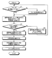
- FIG. 3 is a flowchart illustrating a procedure of an operation of the control unit 16 included in the outdoor unit 3 included in the refrigeration cycle apparatus 1 according to Embodiment 1.
- FIG. 3 shows the operation of the control unit 16 when the compressor 5 is stopped.
- the case where the compressor 5 is stopped includes a case immediately before the start of the operation of the compressor 5 and a case immediately after the stop of the compressor 5.
- the control unit 16 determines whether the fan 6 is rotating in a direction opposite to the normal direction (S1). If the fan 6 is rotating in a direction opposite to the normal direction, it means that the compressor 5 is operating normally, and the amount of current flowing through the compressor 5 is limited to an amount equal to or less than the target current amount. If not.
- the target current amount is a fixed amount and is set in advance.
- the control unit 16 determines that the fan 6 is rotating in a direction opposite to the normal direction (Yes in S1), the control unit 16 records data indicating the temperature detected by the temperature detection unit 12 in the storage unit 17 ( S2).
- the control unit 16 has a temperature detection control counter (not shown in FIG. 2) that is used when estimating the outside air temperature. After performing the operation of step S2, the control unit 16 determines whether or not the count time of the temperature detection control counter is longer than a predetermined estimated time (S3).
- the estimation time is a time required for the control unit 16 to estimate the outside air temperature in step S5 described later. An example of the estimated time is one minute. However, the estimation time is not limited to one minute.
- the control unit 16 determines that the count time is longer than the estimated time (Yes in S3), it clears the count time of the temperature detection control counter (S4).
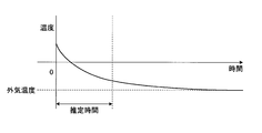
- FIG. 4 is a diagram for explaining an operation when the control unit 16 included in the outdoor unit 3 included in the refrigeration cycle apparatus 1 according to Embodiment 1 estimates the outside air temperature.
- FIG. 4 shows an example in which the temperature detected by the temperature detection unit 12 changes with the lapse of time immediately after the operation of the compressor 5 stops.
- the temperature of the inverter module 11 immediately after the operation of the compressor 5 stops is relatively high. That is, the temperature detected by the temperature detector 12 immediately after the operation of the compressor 5 stops is relatively high.
- the control unit 16 determines the first characteristic that the temperature of the inverter module 11 decreases at a speed within a certain range and converges to the outside air temperature, and the temperature detected by the temperature detection unit 12 over the estimated time. And a function for estimating the outside air temperature. After performing the operation of step S4, the control unit 16 calculates a converging temperature based on the first characteristic and the temperature detected by the temperature detecting unit 12 over the estimated time, and calculates the converging temperature. Is regarded as the outside air temperature, the outside air temperature is estimated (S5).
- the control unit 16 After performing the operation of step S5, the control unit 16 records data indicating the outside air temperature in the storage unit 17 (S6).
- the control unit 16 determines that the time during which the compressor 5 is stopped is longer than a predetermined time, and that the temperatures of the inverter module 11 and the cooler 18 are relatively close to the outside air temperature of the outdoor unit 3.
- the temperature detected by the temperature detection unit 12 may be regarded as the outside air temperature
- the data indicating the temperature detected by the temperature detection unit 12 may be recorded in the storage unit 17 as the data indicating the outside air temperature. That is, the outside air temperature indicated by the data recorded in the storage unit 17 is the outside air temperature estimated by calculation by the control unit 16 or the temperature detected by the temperature detection unit 12.
- step S6 After performing the operation in step S6, the control unit 16 stops the fan 6 (S7). After performing the operation of step S7, the control unit 16 ends the operation related to the recording of the data indicating the outside air temperature in the storage unit 17.
- control unit 16 determines that the fan 6 is not rotating in the opposite direction to the normal direction (No in S1), the control unit 16 rotates the fan 6 in the opposite direction to the normal direction (S8).
- the case where the fan 6 is not rotating in the opposite direction to the normal direction is the case where the fan 6 is stopped or the case where the fan 6 is rotating in the normal direction.
- step S8 the control unit 16 rotates the fan 6 in a direction opposite to the normal direction.
- the air outside the outdoor unit 3 can be positively applied to the cooler 18.
- the inverter module 11 is cooled.
- the estimated time when the control unit 16 estimates the outside air temperature after the operation in step S8 can be made shorter than the estimated time when the control unit 16 does not rotate the fan 6 in the opposite direction to the normal direction. .
- the control unit 16 determines that the time during which the compressor 5 is stopped is longer than a predetermined time, and that the temperatures of the inverter module 11 and the cooler 18 are relatively close to the outside air temperature of the outdoor unit 3. It is not necessary to rotate the fan 6 in the direction opposite to the normal direction. After performing the operation of step S8, the control unit 16 performs the operation of step S2.
- control unit 16 determines that the count time is equal to or shorter than the estimated time (No in S3), the control unit 16 increments the count time of the temperature detection control counter (S9), and returns to step S1.
- control unit 16 may return to step S1 and repeat the operation in and after step S1.
- the control unit 16 determines that the fan 6 is not rotating in the direction opposite to the normal direction, the control unit 16 sets the fan 6 in the direction opposite to the normal direction. Rotate.
- the fan 6 rotates in a direction opposite to the normal direction, the wind having a temperature lower than the temperature of the inverter module 11 when the compressor 5 is operating hits the cooler 18. Thereby, the inverter module 11 is cooled.
- the temperature detection unit 12 can detect the outside air temperature itself or a temperature close to the outside air temperature. Consequently, the control unit 16 can estimate the outside air temperature.
- control unit 16 controls the compressor 5, the fan 6, the LEV 7, and the four-way valve 8 based on the request from the indoor unit 2 and the outside air temperature.
- the request from the indoor unit 2 means a request from the user.
- the outdoor unit 3 included in the refrigeration cycle device 1 according to Embodiment 1 has the temperature detection unit 12 provided inside the inverter module 11.
- the control unit 16 having a function of estimating the outside air temperature is connected to the temperature detection unit 12.
- the inverter module 11 and the control unit 16 are provided on the outdoor control board 10.
- the temperature detection unit 12 Since the temperature detection unit 12 is provided inside the inverter module 11, even when vibrations that exceed expectations occur, for example, when the outdoor control board 10 is replaced in the market, the temperature detection unit 12 can be used. 12 is protected. That is, the control unit 16 can acquire data indicating the temperature detected by the temperature detection unit 12. Consequently, the outdoor unit 3 can detect or estimate the outside air temperature. That is, the refrigeration cycle apparatus 1 can detect or estimate the outside air temperature regardless of whether the unexpected vibration occurs or the outdoor control board 10 is replaced.
- the temperature detection unit 12 is provided inside the inverter module 11, and the inverter module 11 and the control unit 16 are provided on the outdoor control board 10. Therefore, the refrigeration cycle apparatus 1 according to Embodiment 1 is described in Patent Literature 1 even when vibrations more than expected occur, for example, when the outdoor control board 10 is replaced in the market. This does not cause a problem that a lead wire of a certain invention breaks or a connector comes off.
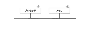
- FIG. 5 shows the LEV 7, the inverter module 11, the temperature detection unit 12, the power module 13, the LEV drive unit 14, the four-way valve drive unit 15, and the control unit 16 included in the outdoor unit 3 included in the refrigeration cycle apparatus 1 according to Embodiment 1.
- FIG. 4 is a diagram illustrating a processor 51 in a case where some or all of the functions of the above are realized by the processor 51. That is, some or all of the functions of the LEV 7, the inverter module 11, the temperature detecting unit 12, the power module 13, the LEV driving unit 14, the four-way valve driving unit 15, and the control unit 16 execute a program stored in the memory 52. It may be realized by the processor 51.
- the processor 51 is a CPU (Central Processing Unit), a processing device, an arithmetic device, a microprocessor, or a DSP (Digital Signal Processor).
- FIG. 5 also shows the memory 52.
- the processor 51 When some or all of the functions of the LEV 7, the inverter module 11, the temperature detection unit 12, the power module 13, the LEV drive unit 14, the four-way valve drive unit 15, and the control unit 16 are realized by the processor 51, a part or all thereof Is realized by the processor 51 and software, firmware, or a combination of software and firmware.
- Software or firmware is described as a program and stored in the memory 52.
- the processor 51 reads out the program stored in the memory 52 and executes the program, so that the LEV 7, the inverter module 11, the temperature detecting unit 12, the power module 13, the LEV driving unit 14, the four-way valve driving unit 15, and the control unit 16 Implements all or part of the functions.
- the program stored in the memory 52 describes a procedure or method executed by a part or all of the LEV 7, the inverter module 11, the temperature detecting unit 12, the power module 13, the LEV driving unit 14, the four-way valve driving unit 15, and the control unit 16. It can also be said to be executed by a computer.
- the memory 52 is, for example, a non-volatile memory such as a RAM (Random Access Memory), a ROM (Read Only Memory), a flash memory, an EPROM (Erasable Programmable Read Only Memory), and an EEPROM (registered trademark) (Electrically Erasable Programmable Read-Only Memory).
- a non-volatile memory such as a RAM (Random Access Memory), a ROM (Read Only Memory), a flash memory, an EPROM (Erasable Programmable Read Only Memory), and an EEPROM (registered trademark) (Electrically Erasable Programmable Read-Only Memory).
- a volatile semiconductor memory a magnetic disk, a flexible disk, an optical disk, a compact disk, a mini disk, a DVD (Digital Versatile Disk), or the like.
- FIG. 6 illustrates the LEV 7, the inverter module 11, the temperature detector 12, the power module 13, the LEV drive unit 14, the four-way valve drive unit 15, and the control unit 16 included in the outdoor unit 3 included in the refrigeration cycle apparatus 1 according to Embodiment 1.
- 6 is a diagram showing a processing circuit 61 in a case where a part or all of the processing is realized by the processing circuit 61.
- FIG. That is, a part or all of the LEV 7, the inverter module 11, the temperature detecting unit 12, the power module 13, the LEV driving unit 14, the four-way valve driving unit 15, and the control unit 16 may be realized by the processing circuit 61.
- the processing circuit 61 is dedicated hardware.
- the processing circuit 61 is, for example, a single circuit, a composite circuit, a programmed processor, a parallel programmed processor, an ASIC (Application Specific Integrated Circuit), an FPGA (Field-Programmable Gate Array), or a combination thereof. It is.
- Part of the LEV 7, the inverter module 11, the temperature detecting unit 12, the power module 13, the LEV driving unit 14, the four-way valve driving unit 15, and the control unit 16 may be dedicated hardware separate from the rest.
- the plurality of functions of the LEV 7, the inverter module 11, the temperature detecting unit 12, the power module 13, the LEV driving unit 14, the four-way valve driving unit 15, and the control unit 16 a part of the plurality of functions is realized by software or firmware, The rest of the plurality of functions may be realized by dedicated hardware. As described above, the plurality of functions of the LEV 7, the inverter module 11, the temperature detecting unit 12, the power module 13, the LEV driving unit 14, the four-way valve driving unit 15, and the control unit 16 are hardware, software, firmware, or a combination thereof. It can be realized by.
- FIG. 7 is a diagram illustrating a configuration of the air-conditioning apparatus 70 according to Embodiment 1.
- the air conditioner 70 has the refrigeration cycle device 1 according to the first embodiment.
- FIG. 8 is a diagram showing a configuration of the hot water supply device 80 according to Embodiment 1.
- hot water supply device 80 has refrigeration cycle device 1 according to the first embodiment.
- the refrigeration cycle device 1 is used by being provided in, for example, the air conditioner 70 or the hot water supply device 80.
- Embodiment 2 FIG. Next, a second embodiment will be described.
- the configuration of the refrigeration cycle device according to Embodiment 2 is the same as the configuration of refrigeration cycle device 1 according to Embodiment 1.
- the operation of the control unit 16 differs between the second embodiment and the first embodiment.
- control unit 16 estimates the outside air temperature when compressor 5 is stopped.
- the control unit 16 estimates the outside air temperature when the compressor 5 is operating.
- parts different from the first embodiment will be mainly described.
- control unit 16 estimates the outside air temperature when the compressor 5 is operating, using the second characteristic.
- the control unit 16 has functions not described in the first embodiment, in addition to the functions described in the first embodiment. Hereinafter, functions of the control unit 16 that are not described in the first embodiment will be described.
- the control unit 16 When the time during which the compressor 5 is operating exceeds a predetermined first time, the control unit 16 performs control to supply a constant current to the compressor 5 for a predetermined second time. Thereafter, the control unit 16 rotates the fan 6 in the direction opposite to the normal direction for a predetermined third time, and controls the temperature outside the outdoor unit 3 based on the temperature detected by the temperature detection unit 12. Is estimated.
- the control unit 16 records data indicating the estimated outside air temperature in the storage unit 17, and after recording the data in the storage unit 17, the data recorded in the storage unit 17 until the next time the outside air temperature is specified or estimated. , The number of rotations of the compressor 5 per unit time, the number of rotations of the fan 6 per unit time, and the opening of the LEV 7 are controlled.
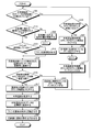
- FIG. 9 is a flowchart illustrating an example of an operation procedure of the control unit 16 included in the outdoor unit 3 included in the refrigeration cycle apparatus 1 according to Embodiment 2.
- FIG. 9 shows the operation of the control unit 16 when the compressor 5 is operating.
- the control unit 16 determines whether data indicating the outside air temperature is stored in the storage unit 17 (S11). When the control unit 16 determines that the data indicating the outside air temperature is not recorded in the storage unit 17 (No in S11), the control unit 16 determines whether the amount of current flowing to the compressor 5 is limited (S12). .
- the case where the amount of current flowing through the compressor 5 is not limited is a case where the compressor 5 is performing a normal operation. For example, in step S12, when the amount of current flowing to the compressor 5 is the target current amount, the control unit 16 determines that the amount of current flowing to the compressor 5 is limited. When the amount of current flowing through the compressor 5 is larger than the target current amount, the control unit 16 determines that the amount of current flowing through the compressor 5 is not limited.
- the target current amount is a fixed amount and is set in advance.
- the control unit 16 determines whether the fan 6 is rotating in a direction opposite to the normal direction (S13). ). When the control unit 16 determines that the fan 6 is rotating in the direction opposite to the normal direction (Yes in S13), the control unit 16 records data indicating the temperature detected by the temperature detection unit 12 in the storage unit 17 ( S14). When determining that the fan 6 is not rotating in the opposite direction to the normal direction (No in S13), the controller 16 rotates the fan 6 in the opposite direction to the normal direction (S15). After performing the operation of step S15, the control unit 16 performs the operation of step S14.
- the control unit 16 determines whether the count time of the temperature detection control counter is longer than a predetermined estimated time (S16).
- the estimation time is a time required for estimation when the control unit 16 estimates the outside air temperature in step S18 described later.
- An example of the estimated time is one minute. However, the estimation time is not limited to one minute.
- the control unit 16 clears the count time of the temperature detection control counter (S17).
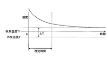
- FIG. 10 is a diagram for explaining an operation when the control unit 16 included in the outdoor unit 3 included in the refrigeration cycle apparatus 1 according to Embodiment 2 estimates the outside air temperature.
- FIG. 10 shows that the temperature detected by the temperature detection unit 12 indicates the lapse of time when the amount of current flowing through the compressor 5 is limited and the fan 6 is rotating in the direction opposite to the normal direction.
- FIG. 10 shows that the temperature detected by the temperature detection unit 12 indicates the lapse of time when the amount of current flowing through the compressor 5 is limited and the fan 6 is rotating in the direction opposite to the normal direction.
- the control unit 16 determines the second characteristic that the temperature of the inverter module 11 decreases at a speed within a certain range and converges to the convergence temperature T1, the temperature detected by the temperature detection unit 12 over the estimated time, and the convergence temperature.
- the outside air temperature T can be estimated based on the third characteristic that T1 is higher than a predetermined temperature ⁇ T than the outside air temperature T.
- the inverter module 11 includes a semiconductor switch.
- the predetermined temperature ⁇ T is determined based on the amount of heat generated in the semiconductor switch of the inverter module 11. More specifically, for example, the predetermined temperature ⁇ T is determined based on a target current amount flowing through the compressor 5.
- the predetermined temperature ⁇ T is specified in advance, for example, by experiment or by calculation.
- the control unit 16 After performing the operation of step S17, the control unit 16 sets the above-described second characteristic, the temperature detected by the temperature detection unit 12 over the estimated time, and the convergence temperature T1 to a predetermined temperature ⁇ T from the outside air temperature T.
- the outside temperature T is estimated based on the third characteristic that the temperature is higher (S18).
- the control unit 16 calculates the convergence temperature T1 based on the above-described second characteristic and the temperature detected by the temperature detection unit 12 over the estimated time, and is determined in advance from the convergence temperature T1.
- the outside air temperature T is estimated by subtracting the temperature ⁇ T (S18).
- control unit 16 After performing the operation of step S18, the control unit 16 records data indicating the outside air temperature in the storage unit 17 (S19). After performing the operation of step S19, the control unit 16 rotates the fan 6 in a normal direction (S20). After performing the operation in step S20, the control unit 16 causes the compressor 5 to perform a normal operation (S21). After performing the operation in step S21, the control unit 16 ends the operation related to the recording of the data indicating the outside air temperature in the storage unit 17.
- the controller 16 determines that the amount of current flowing to the compressor 5 is not limited (No in S12), the controller 16 limits the amount of current flowing to the compressor 5 (S22). For example, in step S22, the control unit 16 matches the amount of current flowing to the compressor 5 with the target current amount. When the amount of current flowing through the compressor 5 matches the target current amount, the amount of heat generated by the inverter module 11 can be made constant. As a result, the control unit 16 can estimate the outside air temperature. After performing the operation in step S22, the control unit 16 performs the operation in step S11.
- control unit 16 determines that the count time is equal to or shorter than the estimated time (No in S16)
- the control unit 16 increments the count time of the temperature detection control counter (S23). After performing the operation of step S23, the control unit 16 performs the operation of step S11.
- the control unit 16 determines whether the count time of the outside air temperature storage time counter is longer than 60 minutes (S24). ).
- the control unit 16 has an outside air temperature storage time counter (not shown).
- the outside air temperature storage time counter counts an elapsed time since data indicating the outside air temperature is recorded in the storage unit 17.
- the above “60 minutes” is an example of a criterion and may be changed.
- control unit 16 determines that the count time of the outside air temperature storage time counter is longer than 60 minutes (Yes in S24), it clears the count time of the outside air temperature storage time counter (S25). After performing the operation of step S25, the control unit 16 clears the data indicating the outside air temperature recorded in the storage unit 17 (S26). The outside air temperature may change due to the weather. In the second embodiment, when the compressor 5 is operating, when the count time of the outside air temperature storage time counter is longer than 60 minutes, the control unit 16 determines the outside air temperature stored in the storage unit 17 in step S26. Clear the data indicating. After performing the operation of step S26, the control unit 16 performs the operation of step S11.
- control unit 16 determines that the count time of the outside air temperature storage time counter is 60 minutes or less (No in S24).
- the control unit 16 increments the count time of the outside air temperature storage time counter (S27). After performing the operation of step S27, the control unit 16 performs the operation of step S11.
- control unit 16 of the second embodiment can estimate the outside air temperature when the compressor 5 is operating.
- the refrigeration cycle apparatus 1 according to the second embodiment includes the processor, the LEV 7, the inverter module 11, the temperature detector 12, the power module 13, the LEV driver 14, the four-way valve driver 15, and the controller 16.
- the memory is a memory having the same function as the memory 52.
- the whole may be realized by a processing circuit having a function equivalent to that of the processing circuit 61 of the first embodiment.
- the refrigeration cycle apparatus 1 according to Embodiment 2 may also be provided in an air conditioner or a hot water supply apparatus, similarly to the refrigeration cycle apparatus 1 according to Embodiment 1.
- Refrigeration cycle device 2 indoor unit, 3 outdoor unit, 4 piping, 5 compressor, 5a compressor motor, 6 fan, 6a fan motor, 7 linear electronic expansion valve, 8 four-way valve, 9 heat exchanger, 10 outdoor control Substrate, 11 inverter module, 12 temperature detection unit, 13 power module, 14 linear electronic expansion valve drive unit, 15 ⁇ four-way valve drive unit, 16 control unit, 17 storage unit, 18 cooler, 51 processor, 52 memory, 61 processing circuit , 70 air conditioner, 80 water heater.
Landscapes
- Engineering & Computer Science (AREA)
- Physics & Mathematics (AREA)
- Mechanical Engineering (AREA)
- Thermal Sciences (AREA)
- General Engineering & Computer Science (AREA)
- Air Conditioning Control Device (AREA)
Abstract
冷凍サイクル装置(1)は、冷媒を圧縮する圧縮機(5)、ファン(6)、冷媒の流量を調整するリニア電子膨張弁(7)、及び室外制御基板(10)を含む室外機(3)を有する。圧縮機(5)は、圧縮機モータを含む。室外機(3)は、室外制御基板(10)に設けられており、圧縮機モータを駆動するインバータモジュールと、インバータモジュールの内部に設けられた温度検出部と、室外制御基板(10)に設けられており、圧縮機(5)の停止中に温度検出部によって検出された温度をもとに室外機(3)の外部の気温である外気温度を推定し、温度検出部によって検出された温度又は推定された外気温度をもとに、圧縮機(5)の単位時間当たりの回転数、ファン(6)の単位時間当たりの回転数、及びリニア電子膨張弁(7)の開度を制御する制御部とを更に有する。
Description
本発明は、圧縮機、ファン、リニア電子膨張弁及び室外制御基板を含む室外機を有する冷凍サイクル装置と、冷凍サイクル装置を有する空気調和装置及び給湯装置とに関する。
室外熱交換器側に配設された温度センサを有し、運転中であるか停止中であるかにかかわらず温度センサによって所定の時間毎に温度を検知し、検知した温度に基づいて外気温度を把握する空気調和機が提案されている(例えば、特許文献1参照)。特許文献1に記載されている空気調和機は、運転停止中に、直前に把握した外気温度と温度センサによって検知された現在の温度との差が所定の温度以上に大きい場合、直前に把握した外気温度を現在の外気温度として保持する制御手段を有する。
しかしながら、上記の従来の技術では、温度センサは、制御手段から離れているので、リード線及びコネクタを介して制御手段と接続する必要がある。想定を超える振動が生じた場合、又は、市場において基板を交換する場合、リード線が切れたり、コネクタが外れたりして、制御手段が外気温度を検出できなくなり、空気調和機が動作することができなくなる恐れがある。
本発明は、上記に鑑みてなされたものであって、想定を超える振動が生じた場合であっても、基板が交換された場合であっても、外気温度を検出又は推定することができる冷凍サイクル装置を得ることを目的とする。
上述した課題を解決し、目的を達成するために、本発明に係る冷凍サイクル装置は、冷媒を圧縮する圧縮機、ファン、冷媒の流量を調整するリニア電子膨張弁、及び室外制御基板を含む室外機を有する冷凍サイクル装置である。圧縮機は、圧縮機モータを含む。室外機は、室外制御基板に設けられており、圧縮機モータを駆動するインバータモジュールと、インバータモジュールの内部に設けられた温度検出部とを更に有する。室外機は、室外制御基板に設けられており、圧縮機の停止中に温度検出部によって検出された温度をもとに室外機の外部の気温である外気温度を推定し、温度検出部によって検出された温度又は推定された外気温度をもとに、圧縮機の単位時間当たりの回転数、ファンの単位時間当たりの回転数、及びリニア電子膨張弁の開度を制御する制御部を更に有する。
本発明に係る冷凍サイクル装置は、想定を超える振動が生じた場合であっても、基板が交換された場合であっても、外気温度を検出又は推定することができるという効果を奏する。
以下に、本発明の実施の形態に係る冷凍サイクル装置、空気調和装置及び給湯装置を図面に基づいて詳細に説明する。なお、この実施の形態によりこの発明が限定されるものではない。
実施の形態1.
まず、実施の形態1に係る冷凍サイクル装置1の構成を説明する。図1は、実施の形態1に係る冷凍サイクル装置1の構成を示す図である。冷凍サイクル装置1は、室内機2と、室外機3と、冷媒が流れる配管4とを有する。配管4は、室内機2と室外機3とを接続している。
まず、実施の形態1に係る冷凍サイクル装置1の構成を説明する。図1は、実施の形態1に係る冷凍サイクル装置1の構成を示す図である。冷凍サイクル装置1は、室内機2と、室外機3と、冷媒が流れる配管4とを有する。配管4は、室内機2と室外機3とを接続している。
室外機3は、冷媒を圧縮する圧縮機5と、ファン6と、冷媒の流量を調整するリニア電子膨張弁7と、冷媒の流路を切り換えるための四方弁8と、熱交換器9と、室外制御基板10とを有する。以下では、リニア電子膨張弁を「LEV」と記載する場合がある。圧縮機5、LEV7、四方弁8、熱交換器9、室内機2及び配管4が冷凍サイクルを構成する。
図2は、実施の形態1に係る冷凍サイクル装置1が有する室外機3の構成を示す図である。図2には、室内機2及び配管4も示されている。室外制御基板10は、圧縮機5、ファン6、LEV7、四方弁8に接続されている。圧縮機5は、圧縮機モータ5aを含む。ファン6は、ファンモータ6aを含む。
室外機3は、圧縮機モータ5aを駆動するインバータモジュール11を更に有する。インバータモジュール11は、室外制御基板10に設けられている。室外機3は、インバータモジュール11の内部に設けられた温度検出部12と、ファンモータ6aを駆動するパワーモジュール13とを更に有する。
室外機3は、LEV7を駆動するリニア電子膨張弁駆動部14と、四方弁8を駆動する四方弁駆動部15とを更に有する。LEV駆動部14及び四方弁駆動部15は、室外制御基板10に設けられている。室外機3は、制御部16を更に有する。制御部16は、インバータモジュール11、パワーモジュール13、LEV駆動部14及び四方弁駆動部15を制御する。制御部16は、室外制御基板10に設けられている。制御部16は、温度検出部12に接続されている。
制御部16は、圧縮機5の停止中に温度検出部12によって検出された温度をもとに室外機3の外部の気温である外気温度を推定する。制御部16は、圧縮機5の停止中に、ファン6を通常の向きと逆の向きに回転させてもよい。制御部16は、温度検出部12によって検出された温度又は推定された外気温度をもとに、圧縮機5の単位時間当たりの回転数と、ファン6の単位時間当たりの回転数と、LEV7の開度とを制御する。
具体的には、制御部16は、温度検出部12によって検出された温度又は推定された外気温度をもとに、インバータモジュール11を制御することにより、圧縮機5の単位時間当たりの回転数を制御する。制御部16は、温度検出部12によって検出された温度又は推定された外気温度をもとに、パワーモジュール13を制御することにより、ファン6の単位時間当たりの回転数を制御する。制御部16は、温度検出部12によって検出された温度又は推定された外気温度をもとに、LEV駆動部14を制御することにより、LEV7の開度を制御する。
室外機3は、制御部16の内部に設けられた記憶部17を更に有する。記憶部17の例は、半導体メモリである。記憶部17は、制御部16の内部以外の室外制御基板10に設けられていてもよい。制御部16は、温度検出部12によって検出された温度を外気温度と特定して特定された外気温度を示すデータを記憶部17に記録する。又は、制御部16は、推定された外気温度を示すデータを記憶部17に記録する。制御部16は、データを記憶部17に記録した後、次に外気温度を特定又は推定するまで、記憶部17に記録されたデータが示す外気温度をもとに、圧縮機5の単位時間当たりの回転数と、ファン6の単位時間当たりの回転数と、LEV7の開度とを制御する。
室外機3は、インバータモジュール11に接続されている冷却器18を更に有する。冷却器18は、ファン6の回転により発生する風を用いてインバータモジュール11の熱を室外制御基板10の外部に排出する。なお、冷却器18はインバータモジュール11に接続されていなくてもよい。パワーモジュール13は、冷却器18に接続されていてもよい。パワーモジュール13は、冷却器18以外の冷却器に接続されていてもよい。冷却器18以外の冷却器は、冷却器18と同等の機能を有する冷却器である。
次に、実施の形態1に係る冷凍サイクル装置1が有する室外機3に含まれている制御部16の動作を説明する。図3は、実施の形態1に係る冷凍サイクル装置1が有する室外機3に含まれている制御部16の動作の手順を示すフローチャートである。図3は、圧縮機5が停止している場合の制御部16の動作を示している。圧縮機5が停止している場合は、圧縮機5の動作の開始の直前の場合と、圧縮機5の停止の直後の場合とを含む。
制御部16は、ファン6が通常の向きと逆の向きに回転しているか否かを判断する(S1)。ファン6が通常の向きと逆の向きに回転している場合は、圧縮機5が通常に動作している場合であって、圧縮機5に流れる電流の量が目標電流量以下の量に制限されていない場合である。目標電流量は、一定の量であって、あらかじめ設定される。制御部16は、ファン6が通常の向きと逆の向きに回転していると判断した場合(S1でYes)、温度検出部12によって検出された温度を示すデータを記憶部17に記録する(S2)。
制御部16は、図2には示されていないが外気温度を推定する際に用いられる温度検出制御カウンタを有している。制御部16は、ステップS2の動作を行った後、温度検出制御カウンタのカウント時間があらかじめ決められた推定時間より長いか否かを判断する(S3)。推定時間は、後述するステップS5において制御部16が外気温度を推定する際の推定に要する時間である。推定時間の例は、1分である。しかしながら、推定時間は1分に限定されない。制御部16は、カウント時間が推定時間より長いと判断した場合(S3でYes)、温度検出制御カウンタのカウント時間をクリアする(S4)。
図4は、実施の形態1に係る冷凍サイクル装置1が有する室外機3に含まれている制御部16が外気温度を推定する際の動作を説明するための図である。図4は、圧縮機5の動作が停止した直後以降において、温度検出部12によって検出された温度が時間の経過と共に変化する様子の例を示している。圧縮機5の動作が停止した直後のインバータモジュール11の温度は、比較的高い。つまり、圧縮機5の動作が停止した直後に温度検出部12によって検出された温度は、比較的高い。
制御部16は、インバータモジュール11の温度が一定の範囲内の速度で低下して外気温度に収束するという第1の特性と、推定時間にわたって温度検出部12によって検出された温度とをもとに、外気温度を推定する機能を有する。制御部16は、ステップS4の動作を行った後、上記の第1の特性と、推定時間にわたって温度検出部12によって検出された温度とをもとに、収束する温度を計算し、収束する温度を外気温度とみなすことにより外気温度を推定する(S5)。
制御部16は、ステップS5の動作を行った後、外気温度を示すデータを記憶部17に記録する(S6)。制御部16は、圧縮機5が停止している時間があらかじめ決められた時間より長くてインバータモジュール11及び冷却器18の温度が室外機3の外部の気温に比較的近いことが分かっている場合、温度検出部12によって検出された温度が外気温度であるとみなして、温度検出部12によって検出された温度を示すデータを、外気温度を示すデータとして記憶部17に記録してもよい。すなわち、記憶部17に記録されるデータが示す外気温度は、制御部16が計算することによって推定した外気温度であるか、温度検出部12によって検出された温度である。
制御部16は、ステップS6の動作を行った後、ファン6を停止させる(S7)。制御部16は、ステップS7の動作を行った後、外気温度を示すデータの記憶部17への記録に関連する動作を終了する。
制御部16は、ファン6が通常の向きと逆の向きに回転していないと判断した場合(S1でNo)、ファン6を通常の向きと逆の向きに回転させる(S8)。ファン6が通常の向きと逆の向きに回転していない場合は、ファン6が停止している場合、又は、ファン6が通常の向きに回転している場合である。
上述の通り、ステップS8において、制御部16はファン6を通常の向きと逆の向きに回転させる。制御部16がファン6を通常の向きと逆の向きに回転させることにより、室外機3の外部の空気を冷却器18に積極的に当てることができる。これにより、インバータモジュール11は冷却される。ひいては、ステップS8の動作の後に制御部16が外気温度を推定する際の推定時間を、制御部16がファン6を通常の向きと逆の向きに回転させない場合の推定時間より短くすることができる。
制御部16は、圧縮機5が停止している時間があらかじめ決められた時間より長くてインバータモジュール11及び冷却器18の温度が室外機3の外部の気温に比較的近いことが分かっている場合、ファン6を通常の向きと逆の向きに回転させなくてもよい。制御部16は、ステップS8の動作を行った後、ステップS2の動作を行う。
制御部16は、カウント時間が推定時間以下であると判断した場合(S3でNo)、温度検出制御カウンタのカウント時間をインクリメントし(S9)、ステップS1に戻る。
制御部16は、ステップS7の動作を行った後、ステップS1に戻ってステップS1以降の動作を繰り返し行ってもよい。
上述の通り、圧縮機5が停止している場合、制御部16は、ファン6が通常の向きと逆の向きに回転していないと判断したとき、ファン6を通常の向きと逆の向きに回転させる。ファン6が通常の向きと逆の向きに回転することにより、圧縮機5が動作していたときのインバータモジュール11の温度より低い温度の風が冷却器18に当たる。これにより、インバータモジュール11が冷却される。その結果、温度検出部12は、外気温度そのものを、又は、外気温度に近い温度を検出することができるようになる。ひいては、制御部16は外気温度を推定することができる。
制御部16は、外気温度を示すデータを記憶部17に記録した後、室内機2からの要求及び外気温度をもとに、圧縮機5、ファン6、LEV7及び四方弁8を制御する。室内機2からの要求は、ユーザの要求を意味する。
上述の通り、実施の形態1に係る冷凍サイクル装置1が有する室外機3は、インバータモジュール11の内部に設けられた温度検出部12を有する。外気温度を推定する機能を有する制御部16は、温度検出部12に接続されている。インバータモジュール11及び制御部16は、室外制御基板10に設けられている。
温度検出部12がインバータモジュール11の内部に設けられているので、想定を超える振動が生じた場合であっても、例えば市場において室外制御基板10が交換された場合であっても、温度検出部12は保護される。つまり、制御部16は温度検出部12が検出した温度を示すデータを取得することができる。ひいては、室外機3は外気温度を検出又は推定することができる。すなわち、冷凍サイクル装置1は、想定を超える振動が生じた場合であっても、室外制御基板10が交換された場合であっても、外気温度を検出又は推定することができる。
上述の通り、温度検出部12がインバータモジュール11の内部に設けられていると共に、インバータモジュール11及び制御部16が室外制御基板10に設けられている。そのため、実施の形態1に係る冷凍サイクル装置1は、想定を超える振動が生じた場合であっても、例えば市場において室外制御基板10が交換された場合であっても、特許文献1に記載されている発明が有するリード線が切れたり、コネクタが外れたりするという問題を生じさせない。
図5は、実施の形態1に係る冷凍サイクル装置1が有する室外機3が有するLEV7、インバータモジュール11、温度検出部12、パワーモジュール13、LEV駆動部14、四方弁駆動部15及び制御部16の一部又は全部の機能がプロセッサ51によって実現される場合のプロセッサ51を示す図である。つまり、LEV7、インバータモジュール11、温度検出部12、パワーモジュール13、LEV駆動部14、四方弁駆動部15及び制御部16の一部又は全部の機能は、メモリ52に格納されるプログラムを実行するプロセッサ51によって実現されてもよい。
プロセッサ51は、CPU(Central Processing Unit)、処理装置、演算装置、マイクロプロセッサ、又はDSP(Digital Signal Processor)である。図5には、メモリ52も示されている。
LEV7、インバータモジュール11、温度検出部12、パワーモジュール13、LEV駆動部14、四方弁駆動部15及び制御部16の一部又は全部の機能がプロセッサ51によって実現される場合、当該一部又は全部の機能は、プロセッサ51と、ソフトウェア、ファームウェア、又は、ソフトウェア及びファームウェアとの組み合わせにより実現される。ソフトウェア又はファームウェアはプログラムとして記述され、メモリ52に格納される。プロセッサ51は、メモリ52に記憶されたプログラムを読み出して実行することにより、LEV7、インバータモジュール11、温度検出部12、パワーモジュール13、LEV駆動部14、四方弁駆動部15及び制御部16の一部又は全部の機能を実現する。
すなわち、LEV7、インバータモジュール11、温度検出部12、パワーモジュール13、LEV駆動部14、四方弁駆動部15及び制御部16の一部又は全部の機能がプロセッサ51によって実現される場合、冷凍サイクル装置1は、LEV7、インバータモジュール11、温度検出部12、パワーモジュール13、LEV駆動部14、四方弁駆動部15及び制御部16の一部又は全部によって実行されるステップが結果的に実行されることになるプログラムを格納するためのメモリ52を有する。
メモリ52に格納されるプログラムは、LEV7、インバータモジュール11、温度検出部12、パワーモジュール13、LEV駆動部14、四方弁駆動部15及び制御部16の一部又は全部が実行する手順又は方法をコンピュータに実行させるものであるともいえる。
メモリ52は、例えば、RAM(Random Access Memory)、ROM(Read Only Memory)、フラッシュメモリ、EPROM(Erasable Programmable Read Only Memory)、EEPROM(登録商標)(Electrically Erasable Programmable Read-Only Memory)等の不揮発性もしくは揮発性の半導体メモリ、磁気ディスク、フレキシブルディスク、光ディスク、コンパクトディスク、ミニディスク又はDVD(Digital Versatile Disk)等である。
図6は、実施の形態1に係る冷凍サイクル装置1が有する室外機3が有するLEV7、インバータモジュール11、温度検出部12、パワーモジュール13、LEV駆動部14、四方弁駆動部15及び制御部16の一部又は全部が処理回路61によって実現される場合の処理回路61を示す図である。つまり、LEV7、インバータモジュール11、温度検出部12、パワーモジュール13、LEV駆動部14、四方弁駆動部15及び制御部16の一部又は全部は、処理回路61によって実現されてもよい。
処理回路61は、専用のハードウェアである。処理回路61は、例えば、単一回路、複合回路、プログラム化されたプロセッサ、並列プログラム化されたプロセッサ、ASIC(Application Specific Integrated Circuit)、FPGA(Field-Programmable Gate Array)、又はこれらを組み合わせたものである。
LEV7、インバータモジュール11、温度検出部12、パワーモジュール13、LEV駆動部14、四方弁駆動部15及び制御部16の一部は、残部とは別個の専用のハードウェアであってもよい。
LEV7、インバータモジュール11、温度検出部12、パワーモジュール13、LEV駆動部14、四方弁駆動部15及び制御部16の複数の機能について、当該複数の機能の一部がソフトウェア又はファームウェアで実現され、当該複数の機能の残部が専用のハードウェアで実現されてもよい。このように、LEV7、インバータモジュール11、温度検出部12、パワーモジュール13、LEV駆動部14、四方弁駆動部15及び制御部16の複数の機能は、ハードウェア、ソフトウェア、ファームウェア、又はこれらの組み合わせによって実現することができる。
次に、冷凍サイクル装置1の利用例を説明する。図7は、実施の形態1に係る空気調和装置70の構成を示す図である。図7に示す通り、空気調和装置70は、実施の形態1に係る冷凍サイクル装置1を有する。図8は、実施の形態1に係る給湯装置80の構成を示す図である。図8に示す通り、給湯装置80は、実施の形態1に係る冷凍サイクル装置1を有する。上述の通り、冷凍サイクル装置1は、例えば空気調和装置70又は給湯装置80に設けられることによって利用される。
実施の形態2.
次に、実施の形態2について説明する。実施の形態2に係る冷凍サイクル装置の構成は、実施の形態1に係る冷凍サイクル装置1の構成と同じである。実施の形態2と実施の形態1とでは、制御部16の動作が異なる。実施の形態1では、制御部16は、圧縮機5が停止している場合の外気温度を推定する。実施の形態2では、制御部16は、圧縮機5が動作している場合の外気温度を推定する。実施の形態2では、実施の形態1と異なる部分を主に説明する。
次に、実施の形態2について説明する。実施の形態2に係る冷凍サイクル装置の構成は、実施の形態1に係る冷凍サイクル装置1の構成と同じである。実施の形態2と実施の形態1とでは、制御部16の動作が異なる。実施の形態1では、制御部16は、圧縮機5が停止している場合の外気温度を推定する。実施の形態2では、制御部16は、圧縮機5が動作している場合の外気温度を推定する。実施の形態2では、実施の形態1と異なる部分を主に説明する。
圧縮機5が動作している場合、温度検出部12によって検出される温度はインバータモジュール11の温度に近い。そのため、圧縮機5が動作している場合、制御部16は、実施の形態1において用いられた第1の特性をもとに外気温度を推定することはできない。実施の形態2では、後述の通り、制御部16は、第2の特性を用いて、圧縮機5が動作している場合の外気温度を推定する。
制御部16は、実施の形態1において説明された機能に加えて、実施の形態1において説明されていない機能を有する。以下に、制御部16の実施の形態1において説明されていない機能を説明する。制御部16は、圧縮機5が動作している時間があらかじめ決められた第1の時間を超えた場合、あらかじめ決められた第2の時間、圧縮機5に一定の電流を流す制御を行う。その後、制御部16は、あらかじめ決められた第3の時間、ファン6を通常の向きと逆の向きに回転させ、温度検出部12によって検出された温度をもとに室外機3の外部の気温である外気温度を推定する。
制御部16は、推定された外気温度を示すデータを記憶部17に記録し、データを記憶部17に記録した後、次に外気温度を特定又は推定するまで、記憶部17に記録されたデータが示す外気温度をもとに、圧縮機5の単位時間当たりの回転数と、ファン6の単位時間当たりの回転数と、LEV7の開度とを制御する。
次に、実施の形態2に係る冷凍サイクル装置1が有する室外機3に含まれている制御部16の動作の一例を説明する。図9は、実施の形態2に係る冷凍サイクル装置1が有する室外機3に含まれている制御部16の動作の手順の一例を示すフローチャートである。図9は、圧縮機5が動作している場合の制御部16の動作を示している。
制御部16は、外気温度を示すデータが記憶部17に記録されているか否かを判断する(S11)。制御部16は、外気温度を示すデータが記憶部17に記録されていないと判断した場合(S11でNo)、圧縮機5に流れる電流の量が制限されているか否かを判断する(S12)。圧縮機5に流れる電流の量が制限されていない場合は、圧縮機5が通常の動作を行っている場合である。例えば、ステップS12において、制御部16は、圧縮機5に流れる電流の量が目標電流量である場合、圧縮機5に流れる電流の量が制限されていると判断する。制御部16は、圧縮機5に流れる電流の量が目標電流量より多い場合、圧縮機5に流れる電流の量は制限されていないと判断する。目標電流量は、一定の量であって、あらかじめ設定される。
制御部16は、圧縮機5に流れる電流の量が制限されていると判断した場合(S12でYes)、ファン6が通常の向きと逆の向きに回転しているか否かを判断する(S13)。制御部16は、ファン6が通常の向きと逆の向きに回転していると判断した場合(S13でYes)、温度検出部12によって検出された温度を示すデータを記憶部17に記録する(S14)。制御部16は、ファン6が通常の向きと逆の向きに回転していないと判断した場合(S13でNo)、ファン6を通常の向きと逆の向きに回転させる(S15)。制御部16は、ステップS15の動作を行った後、ステップS14の動作を行う。
制御部16は、ステップS14の動作を行った後、温度検出制御カウンタのカウント時間があらかじめ決められた推定時間より長いか否かを判断する(S16)。推定時間は、後述するステップS18において制御部16が外気温度を推定する際の推定に要する時間である。推定時間の例は、1分である。しかしながら、推定時間は1分に限定されない。制御部16は、カウント時間が推定時間より長いと判断した場合(S16でYes)、温度検出制御カウンタのカウント時間をクリアする(S17)。
図10は、実施の形態2に係る冷凍サイクル装置1が有する室外機3に含まれている制御部16が外気温度を推定する際の動作を説明するための図である。図10は、圧縮機5に流れる電流の量が制限されていると共に、ファン6が通常の向きと逆の向きに回転している場合において、温度検出部12によって検出された温度が時間の経過と共に変化する様子の例を示している。
圧縮機5に流れる電流の量が制限され、かつファン6が通常の向きと逆の向きに回転した直後のインバータモジュール11の温度は、比較的高い。制御部16は、インバータモジュール11の温度が一定の範囲内の速度で低下して収束温度T1に収束するという第2の特性と、推定時間にわたって温度検出部12によって検出された温度と、収束温度T1が外気温度Tよりあらかじめ決められた温度ΔTより高いという第3の特性とをもとに、外気温度Tを推定することができる。
インバータモジュール11は、半導体スイッチを含む。例えば、あらかじめ決められた温度ΔTは、インバータモジュール11の半導体スイッチで発生する熱量をもとに決まる。更に言うと、例えば、あらかじめ決められた温度ΔTは、圧縮機5に流れる目標電流量をもとに決まる。あらかじめ決められた温度ΔTは、例えば実験によって又は計算によってあらかじめ特定される。
制御部16は、ステップS17の動作を行った後、上記の第2の特性と、推定時間にわたって温度検出部12によって検出された温度と、収束温度T1が外気温度Tよりあらかじめ決められた温度ΔTより高いという第3の特性とをもとに、外気温度Tを推定する(S18)。具体的には、制御部16は、上記の第2の特性と、推定時間にわたって温度検出部12によって検出された温度とをもとに収束温度T1を計算し、収束温度T1からあらかじめ決められた温度ΔTを差し引くことによって外気温度Tを推定する(S18)。
制御部16は、ステップS18の動作を行った後、外気温度を示すデータを記憶部17に記録する(S19)。制御部16は、ステップS19の動作を行った後、ファン6を通常の向きに回転させる(S20)。制御部16は、ステップS20の動作を行った後、圧縮機5に通常の動作を行わせる(S21)。制御部16は、ステップS21の動作を行った後、外気温度を示すデータの記憶部17への記録に関連する動作を終了する。
制御部16は、圧縮機5に流れる電流の量が制限されていないと判断した場合(S12でNo)、圧縮機5に流れる電流の量を制限する(S22)。例えば、ステップS22において、制御部16は、圧縮機5に流れる電流の量を目標電流量に一致させる。圧縮機5に流れる電流の量が目標電流量に一致すると、インバータモジュール11の発熱量を一定にすることができる。その結果、制御部16は、外気温度を推定することができるようになる。制御部16は、ステップS22の動作を行った後、ステップS11の動作を行う。
制御部16は、カウント時間が推定時間以下であると判断した場合(S16でNo)、温度検出制御カウンタのカウント時間をインクリメントする(S23)。制御部16は、ステップS23の動作を行った後、ステップS11の動作を行う。
制御部16は、外気温度を示すデータが記憶部17に記録されていると判断した場合(S11でYes)、外気温度保存時間カウンタのカウント時間が60分より長いか否かを判断する(S24)。制御部16は、図示されていないが、外気温度保存時間カウンタを有している。外気温度保存時間カウンタは、外気温度を示すデータが記憶部17に記録されてからの経過時間をカウントする。上記の「60分」は、判断基準の一例であって、変更されてもよい。
制御部16は、外気温度保存時間カウンタのカウント時間が60分より長いと判断した場合(S24でYes)、外気温度保存時間カウンタのカウント時間をクリアする(S25)。制御部16は、ステップS25の動作を行った後、記憶部17に記録されている外気温度を示すデータをクリアする(S26)。外気温度は、天候の影響により変化する場合がある。圧縮機5が動作している場合、実施の形態2では、外気温度保存時間カウンタのカウント時間が60分より長いとき、ステップS26において、制御部16は、記憶部17に記録されている外気温度を示すデータをクリアする。制御部16は、ステップS26の動作を行った後、ステップS11の動作を行う。
制御部16は、外気温度保存時間カウンタのカウント時間が60分以下であると判断した場合(S24でNo)、外気温度保存時間カウンタのカウント時間をインクリメントする(S27)。制御部16は、ステップS27の動作を行った後、ステップS11の動作を行う。
上述の通り、実施の形態2の制御部16は、圧縮機5が動作している場合において、外気温度を推定することができる。
実施の形態2に係る冷凍サイクル装置1が有する室外機3が有するLEV7、インバータモジュール11、温度検出部12、パワーモジュール13、LEV駆動部14、四方弁駆動部15及び制御部16の一部又は全部の機能は、実施の形態1のプロセッサ51と同等の機能を有するプロセッサによって実現されてもよい。その場合、実施の形態2に係る冷凍サイクル装置1は、当該プロセッサと、LEV7、インバータモジュール11、温度検出部12、パワーモジュール13、LEV駆動部14、四方弁駆動部15及び制御部16の一部又は全部によって実行されるステップが結果的に実行されることになるプログラムを格納するためのメモリ52とを有する。当該メモリは、メモリ52と同等の機能を有するメモリである。
実施の形態2に係る冷凍サイクル装置1が有する室外機3が有するLEV7、インバータモジュール11、温度検出部12、パワーモジュール13、LEV駆動部14、四方弁駆動部15及び制御部16の一部又は全部は、実施の形態1の処理回路61と同等の機能を有する処理回路によって実現されてもよい。
実施の形態2に係る冷凍サイクル装置1も、実施の形態1に係る冷凍サイクル装置1と同様に、空気調和装置又は給湯装置に設けられてもよい。
以上の実施の形態に示した構成は、本発明の内容の一例を示すものであり、別の公知の技術と組み合わせることも可能であるし、本発明の要旨を逸脱しない範囲で、構成の一部を省略又は変更することも可能である。
1 冷凍サイクル装置、2 室内機、3 室外機、4 配管、5 圧縮機、5a 圧縮機モータ、6 ファン、6a ファンモータ、7 リニア電子膨張弁、8 四方弁、9 熱交換器、10 室外制御基板、11 インバータモジュール、12 温度検出部、13 パワーモジュール、14 リニア電子膨張弁駆動部、15 四方弁駆動部、16 制御部、17 記憶部、18 冷却器、51 プロセッサ、52 メモリ、61 処理回路、70 空気調和装置、80 給湯装置。
Claims (7)
- 冷媒を圧縮する圧縮機、ファン、前記冷媒の流量を調整するリニア電子膨張弁、及び室外制御基板を有する室外機を備える冷凍サイクル装置であって、
前記圧縮機は、圧縮機モータを含み、
前記室外機は、
前記室外制御基板に設けられており、前記圧縮機モータを駆動するインバータモジュールと、
前記インバータモジュールの内部に設けられた温度検出部と、
前記室外制御基板に設けられており、前記圧縮機の停止中に前記温度検出部によって検出された温度をもとに前記室外機の外部の気温である外気温度を推定し、前記温度検出部によって検出された温度又は推定された前記外気温度をもとに、前記圧縮機の単位時間当たりの回転数、前記ファンの単位時間当たりの回転数、及び前記リニア電子膨張弁の開度を制御する制御部とを更に有する
冷凍サイクル装置。 - 前記制御部は、前記圧縮機の停止中に、前記ファンを通常の向きと逆の向きに回転させる
請求項1に記載の冷凍サイクル装置。 - 前記室外機は、前記制御部の内部又は前記室外制御基板に設けられた記憶部を更に有し、
前記制御部は、前記温度検出部によって検出された温度を前記外気温度と特定して特定された前記外気温度を示すデータを前記記憶部に記録し、又は、推定された前記外気温度を示すデータを前記記憶部に記録し、データを前記記憶部に記録した後、次に外気温度を特定又は推定するまで、前記記憶部に記録されたデータが示す前記外気温度をもとに、前記圧縮機の単位時間当たりの回転数と、前記ファンの単位時間当たりの回転数と、前記リニア電子膨張弁の開度とを制御する
請求項1又は2に記載の冷凍サイクル装置。 - 前記制御部は、前記圧縮機が動作している時間があらかじめ決められた第1の時間を超えた場合、あらかじめ決められた第2の時間、前記圧縮機に一定の電流を流す制御を行い、あらかじめ決められた第3の時間、前記ファンを通常の向きと逆の向きに回転させ、前記温度検出部によって検出された温度をもとに前記室外機の外部の気温である外気温度を推定し、推定された前記外気温度を示すデータを前記記憶部に記録し、前記データを前記記憶部に記録した後、次に外気温度を特定又は推定するまで、前記記憶部に記録された前記データが示す前記外気温度をもとに、前記圧縮機の単位時間当たりの回転数と、前記ファンの単位時間当たりの回転数と、前記リニア電子膨張弁の開度とを制御する
請求項3に記載の冷凍サイクル装置。 - 前記室外機は、前記制御部の内部又は前記室外制御基板に設けられた記憶部を更に有し、
前記制御部は、前記圧縮機が動作している時間があらかじめ決められた第1の時間を超えた場合、あらかじめ決められた第2の時間、前記圧縮機に一定の電流を流す制御を行い、あらかじめ決められた第3の時間、前記ファンを通常の向きと逆の向きに回転させ、前記温度検出部によって検出された温度をもとに前記室外機の外部の気温である外気温度を推定し、推定された前記外気温度を示すデータを前記記憶部に記録し、前記データを前記記憶部に記録した後、次に外気温度を特定又は推定するまで、前記記憶部に記録された前記データが示す前記外気温度をもとに、前記圧縮機の単位時間当たりの回転数と、前記ファンの単位時間当たりの回転数と、前記リニア電子膨張弁の開度とを制御する
請求項1又は2に記載の冷凍サイクル装置。 - 請求項1から5のいずれか1項に記載の冷凍サイクル装置を備える空気調和装置。
- 請求項1から5のいずれか1項に記載の冷凍サイクル装置を備える給湯装置。
Priority Applications (2)
| Application Number | Priority Date | Filing Date | Title |
|---|---|---|---|
| PCT/JP2018/025049 WO2020008495A1 (ja) | 2018-07-02 | 2018-07-02 | 冷凍サイクル装置、空気調和装置及び給湯装置 |
| JP2020528548A JP6877644B2 (ja) | 2018-07-02 | 2018-07-02 | 冷凍サイクル装置、空気調和装置及び給湯装置 |
Applications Claiming Priority (1)
| Application Number | Priority Date | Filing Date | Title |
|---|---|---|---|
| PCT/JP2018/025049 WO2020008495A1 (ja) | 2018-07-02 | 2018-07-02 | 冷凍サイクル装置、空気調和装置及び給湯装置 |
Publications (1)
| Publication Number | Publication Date |
|---|---|
| WO2020008495A1 true WO2020008495A1 (ja) | 2020-01-09 |
Family
ID=69059502
Family Applications (1)
| Application Number | Title | Priority Date | Filing Date |
|---|---|---|---|
| PCT/JP2018/025049 Ceased WO2020008495A1 (ja) | 2018-07-02 | 2018-07-02 | 冷凍サイクル装置、空気調和装置及び給湯装置 |
Country Status (2)
| Country | Link |
|---|---|
| JP (1) | JP6877644B2 (ja) |
| WO (1) | WO2020008495A1 (ja) |
Citations (9)
| Publication number | Priority date | Publication date | Assignee | Title |
|---|---|---|---|---|
| JPH02217765A (ja) * | 1988-10-12 | 1990-08-30 | Honeywell Inc | 熱ポンプにおいて外部周囲温度を確定する方法および装置 |
| JPH07120049A (ja) * | 1993-08-31 | 1995-05-12 | Toshiba Corp | 空気調和機 |
| JPH07280327A (ja) * | 1994-04-12 | 1995-10-27 | Toshiba Corp | 空気調和機 |
| JP2002098392A (ja) * | 2000-09-26 | 2002-04-05 | Daikin Ind Ltd | 外気温度検出装置 |
| JP2004225929A (ja) * | 2003-01-20 | 2004-08-12 | Sanyo Electric Co Ltd | 空気調和装置及び空気調和装置の制御方法 |
| JP2006183907A (ja) * | 2004-12-27 | 2006-07-13 | Matsushita Electric Ind Co Ltd | 空気調和機 |
| JP2006258340A (ja) * | 2005-03-16 | 2006-09-28 | Matsushita Electric Ind Co Ltd | 空気調和機 |
| JP2011117683A (ja) * | 2009-12-04 | 2011-06-16 | Sharp Corp | 空気調和機およびその制御方法 |
| JP2013053765A (ja) * | 2011-09-01 | 2013-03-21 | Daikin Industries Ltd | 空気調和機 |
-
2018
- 2018-07-02 WO PCT/JP2018/025049 patent/WO2020008495A1/ja not_active Ceased
- 2018-07-02 JP JP2020528548A patent/JP6877644B2/ja not_active Expired - Fee Related
Patent Citations (9)
| Publication number | Priority date | Publication date | Assignee | Title |
|---|---|---|---|---|
| JPH02217765A (ja) * | 1988-10-12 | 1990-08-30 | Honeywell Inc | 熱ポンプにおいて外部周囲温度を確定する方法および装置 |
| JPH07120049A (ja) * | 1993-08-31 | 1995-05-12 | Toshiba Corp | 空気調和機 |
| JPH07280327A (ja) * | 1994-04-12 | 1995-10-27 | Toshiba Corp | 空気調和機 |
| JP2002098392A (ja) * | 2000-09-26 | 2002-04-05 | Daikin Ind Ltd | 外気温度検出装置 |
| JP2004225929A (ja) * | 2003-01-20 | 2004-08-12 | Sanyo Electric Co Ltd | 空気調和装置及び空気調和装置の制御方法 |
| JP2006183907A (ja) * | 2004-12-27 | 2006-07-13 | Matsushita Electric Ind Co Ltd | 空気調和機 |
| JP2006258340A (ja) * | 2005-03-16 | 2006-09-28 | Matsushita Electric Ind Co Ltd | 空気調和機 |
| JP2011117683A (ja) * | 2009-12-04 | 2011-06-16 | Sharp Corp | 空気調和機およびその制御方法 |
| JP2013053765A (ja) * | 2011-09-01 | 2013-03-21 | Daikin Industries Ltd | 空気調和機 |
Also Published As
| Publication number | Publication date |
|---|---|
| JPWO2020008495A1 (ja) | 2020-12-17 |
| JP6877644B2 (ja) | 2021-05-26 |
Similar Documents
| Publication | Publication Date | Title |
|---|---|---|
| JP6548285B2 (ja) | 空気調和機の制御方法及び空気調和機 | |
| US11703242B2 (en) | Avoiding coil freeze in HVAC systems | |
| CN110749056B (zh) | 空调器及其控制方法和装置 | |
| JP6524346B2 (ja) | 空気調和機の室外機 | |
| CN104132423A (zh) | 空调系统防液击的控制方法及控制装置和空调系统 | |
| JP2011202833A (ja) | 空気調和機 | |
| US11255560B2 (en) | Air-conditioning apparatus and method of determining operation condition | |
| US20200191435A1 (en) | Outdoor unit of heat-pump hot water dispenser | |
| WO2017221315A1 (ja) | 除霜判断機器、除霜制御機器及び空気調和機 | |
| WO2020008495A1 (ja) | 冷凍サイクル装置、空気調和装置及び給湯装置 | |
| JP6897736B2 (ja) | 冷凍装置 | |
| JP6301789B2 (ja) | 冷凍サイクルにおける圧縮機の脱調検知システム及び脱調検知方法 | |
| WO2017183070A1 (ja) | 空気調和装置 | |
| JP6458533B2 (ja) | 空気調和装置 | |
| CN118442756A (zh) | 用于冰箱风门的控制方法及装置、冰箱 | |
| JP6555424B2 (ja) | ヒートポンプシステム | |
| WO2021149162A1 (ja) | ヒートポンプ装置、ヒートポンプシステム、空気調和機および冷凍機 | |
| KR101151955B1 (ko) | 차량의 공기조화장치용 전동식압축기의 제어방법 | |
| KR102156141B1 (ko) | 공기 조화기 제어장치 및 압축기 제어방법 | |
| WO2020049633A1 (ja) | 空気調和機の室外機 | |
| JP7066045B2 (ja) | 空気調和機の室内機 | |
| JP7172664B2 (ja) | 空気調和機、空気調和機の制御装置、その制御方法およびプログラム | |
| WO2023062908A1 (ja) | 空気調和機 | |
| JP6234254B2 (ja) | ヒートポンプ給湯機の制御装置及び制御方法 | |
| JP5263036B2 (ja) | 流体送出装置の制御装置 |
Legal Events
| Date | Code | Title | Description |
|---|---|---|---|
| 121 | Ep: the epo has been informed by wipo that ep was designated in this application |
Ref document number: 18925616 Country of ref document: EP Kind code of ref document: A1 |
|
| WWE | Wipo information: entry into national phase |
Ref document number: 2020528548 Country of ref document: JP |
|
| NENP | Non-entry into the national phase |
Ref country code: DE |
|
| 122 | Ep: pct application non-entry in european phase |
Ref document number: 18925616 Country of ref document: EP Kind code of ref document: A1 |