WO2020004509A1 - Système de gestion de batterie - Google Patents
Système de gestion de batterie Download PDFInfo
- Publication number
- WO2020004509A1 WO2020004509A1 PCT/JP2019/025487 JP2019025487W WO2020004509A1 WO 2020004509 A1 WO2020004509 A1 WO 2020004509A1 JP 2019025487 W JP2019025487 W JP 2019025487W WO 2020004509 A1 WO2020004509 A1 WO 2020004509A1
- Authority
- WO
- WIPO (PCT)
- Prior art keywords
- battery
- electric vehicle
- station
- management server
- user
- Prior art date
Links
Images

Classifications
-
- B—PERFORMING OPERATIONS; TRANSPORTING
- B60—VEHICLES IN GENERAL
- B60L—PROPULSION OF ELECTRICALLY-PROPELLED VEHICLES; SUPPLYING ELECTRIC POWER FOR AUXILIARY EQUIPMENT OF ELECTRICALLY-PROPELLED VEHICLES; ELECTRODYNAMIC BRAKE SYSTEMS FOR VEHICLES IN GENERAL; MAGNETIC SUSPENSION OR LEVITATION FOR VEHICLES; MONITORING OPERATING VARIABLES OF ELECTRICALLY-PROPELLED VEHICLES; ELECTRIC SAFETY DEVICES FOR ELECTRICALLY-PROPELLED VEHICLES
- B60L53/00—Methods of charging batteries, specially adapted for electric vehicles; Charging stations or on-board charging equipment therefor; Exchange of energy storage elements in electric vehicles
- B60L53/60—Monitoring or controlling charging stations
- B60L53/68—Off-site monitoring or control, e.g. remote control
-
- B—PERFORMING OPERATIONS; TRANSPORTING
- B60—VEHICLES IN GENERAL
- B60L—PROPULSION OF ELECTRICALLY-PROPELLED VEHICLES; SUPPLYING ELECTRIC POWER FOR AUXILIARY EQUIPMENT OF ELECTRICALLY-PROPELLED VEHICLES; ELECTRODYNAMIC BRAKE SYSTEMS FOR VEHICLES IN GENERAL; MAGNETIC SUSPENSION OR LEVITATION FOR VEHICLES; MONITORING OPERATING VARIABLES OF ELECTRICALLY-PROPELLED VEHICLES; ELECTRIC SAFETY DEVICES FOR ELECTRICALLY-PROPELLED VEHICLES
- B60L53/00—Methods of charging batteries, specially adapted for electric vehicles; Charging stations or on-board charging equipment therefor; Exchange of energy storage elements in electric vehicles
- B60L53/60—Monitoring or controlling charging stations
- B60L53/66—Data transfer between charging stations and vehicles
-
- B—PERFORMING OPERATIONS; TRANSPORTING
- B60—VEHICLES IN GENERAL
- B60L—PROPULSION OF ELECTRICALLY-PROPELLED VEHICLES; SUPPLYING ELECTRIC POWER FOR AUXILIARY EQUIPMENT OF ELECTRICALLY-PROPELLED VEHICLES; ELECTRODYNAMIC BRAKE SYSTEMS FOR VEHICLES IN GENERAL; MAGNETIC SUSPENSION OR LEVITATION FOR VEHICLES; MONITORING OPERATING VARIABLES OF ELECTRICALLY-PROPELLED VEHICLES; ELECTRIC SAFETY DEVICES FOR ELECTRICALLY-PROPELLED VEHICLES
- B60L3/00—Electric devices on electrically-propelled vehicles for safety purposes; Monitoring operating variables, e.g. speed, deceleration or energy consumption
-
- B—PERFORMING OPERATIONS; TRANSPORTING
- B60—VEHICLES IN GENERAL
- B60L—PROPULSION OF ELECTRICALLY-PROPELLED VEHICLES; SUPPLYING ELECTRIC POWER FOR AUXILIARY EQUIPMENT OF ELECTRICALLY-PROPELLED VEHICLES; ELECTRODYNAMIC BRAKE SYSTEMS FOR VEHICLES IN GENERAL; MAGNETIC SUSPENSION OR LEVITATION FOR VEHICLES; MONITORING OPERATING VARIABLES OF ELECTRICALLY-PROPELLED VEHICLES; ELECTRIC SAFETY DEVICES FOR ELECTRICALLY-PROPELLED VEHICLES
- B60L50/00—Electric propulsion with power supplied within the vehicle
- B60L50/50—Electric propulsion with power supplied within the vehicle using propulsion power supplied by batteries or fuel cells
-
- B—PERFORMING OPERATIONS; TRANSPORTING
- B60—VEHICLES IN GENERAL
- B60L—PROPULSION OF ELECTRICALLY-PROPELLED VEHICLES; SUPPLYING ELECTRIC POWER FOR AUXILIARY EQUIPMENT OF ELECTRICALLY-PROPELLED VEHICLES; ELECTRODYNAMIC BRAKE SYSTEMS FOR VEHICLES IN GENERAL; MAGNETIC SUSPENSION OR LEVITATION FOR VEHICLES; MONITORING OPERATING VARIABLES OF ELECTRICALLY-PROPELLED VEHICLES; ELECTRIC SAFETY DEVICES FOR ELECTRICALLY-PROPELLED VEHICLES
- B60L53/00—Methods of charging batteries, specially adapted for electric vehicles; Charging stations or on-board charging equipment therefor; Exchange of energy storage elements in electric vehicles
- B60L53/50—Charging stations characterised by energy-storage or power-generation means
- B60L53/53—Batteries
-
- B—PERFORMING OPERATIONS; TRANSPORTING
- B60—VEHICLES IN GENERAL
- B60L—PROPULSION OF ELECTRICALLY-PROPELLED VEHICLES; SUPPLYING ELECTRIC POWER FOR AUXILIARY EQUIPMENT OF ELECTRICALLY-PROPELLED VEHICLES; ELECTRODYNAMIC BRAKE SYSTEMS FOR VEHICLES IN GENERAL; MAGNETIC SUSPENSION OR LEVITATION FOR VEHICLES; MONITORING OPERATING VARIABLES OF ELECTRICALLY-PROPELLED VEHICLES; ELECTRIC SAFETY DEVICES FOR ELECTRICALLY-PROPELLED VEHICLES
- B60L53/00—Methods of charging batteries, specially adapted for electric vehicles; Charging stations or on-board charging equipment therefor; Exchange of energy storage elements in electric vehicles
- B60L53/60—Monitoring or controlling charging stations
- B60L53/62—Monitoring or controlling charging stations in response to charging parameters, e.g. current, voltage or electrical charge
-
- B—PERFORMING OPERATIONS; TRANSPORTING
- B60—VEHICLES IN GENERAL
- B60L—PROPULSION OF ELECTRICALLY-PROPELLED VEHICLES; SUPPLYING ELECTRIC POWER FOR AUXILIARY EQUIPMENT OF ELECTRICALLY-PROPELLED VEHICLES; ELECTRODYNAMIC BRAKE SYSTEMS FOR VEHICLES IN GENERAL; MAGNETIC SUSPENSION OR LEVITATION FOR VEHICLES; MONITORING OPERATING VARIABLES OF ELECTRICALLY-PROPELLED VEHICLES; ELECTRIC SAFETY DEVICES FOR ELECTRICALLY-PROPELLED VEHICLES
- B60L53/00—Methods of charging batteries, specially adapted for electric vehicles; Charging stations or on-board charging equipment therefor; Exchange of energy storage elements in electric vehicles
- B60L53/60—Monitoring or controlling charging stations
- B60L53/65—Monitoring or controlling charging stations involving identification of vehicles or their battery types
-
- B—PERFORMING OPERATIONS; TRANSPORTING
- B60—VEHICLES IN GENERAL
- B60L—PROPULSION OF ELECTRICALLY-PROPELLED VEHICLES; SUPPLYING ELECTRIC POWER FOR AUXILIARY EQUIPMENT OF ELECTRICALLY-PROPELLED VEHICLES; ELECTRODYNAMIC BRAKE SYSTEMS FOR VEHICLES IN GENERAL; MAGNETIC SUSPENSION OR LEVITATION FOR VEHICLES; MONITORING OPERATING VARIABLES OF ELECTRICALLY-PROPELLED VEHICLES; ELECTRIC SAFETY DEVICES FOR ELECTRICALLY-PROPELLED VEHICLES
- B60L53/00—Methods of charging batteries, specially adapted for electric vehicles; Charging stations or on-board charging equipment therefor; Exchange of energy storage elements in electric vehicles
- B60L53/60—Monitoring or controlling charging stations
- B60L53/67—Controlling two or more charging stations
-
- B—PERFORMING OPERATIONS; TRANSPORTING
- B60—VEHICLES IN GENERAL
- B60L—PROPULSION OF ELECTRICALLY-PROPELLED VEHICLES; SUPPLYING ELECTRIC POWER FOR AUXILIARY EQUIPMENT OF ELECTRICALLY-PROPELLED VEHICLES; ELECTRODYNAMIC BRAKE SYSTEMS FOR VEHICLES IN GENERAL; MAGNETIC SUSPENSION OR LEVITATION FOR VEHICLES; MONITORING OPERATING VARIABLES OF ELECTRICALLY-PROPELLED VEHICLES; ELECTRIC SAFETY DEVICES FOR ELECTRICALLY-PROPELLED VEHICLES
- B60L53/00—Methods of charging batteries, specially adapted for electric vehicles; Charging stations or on-board charging equipment therefor; Exchange of energy storage elements in electric vehicles
- B60L53/80—Exchanging energy storage elements, e.g. removable batteries
-
- B—PERFORMING OPERATIONS; TRANSPORTING
- B60—VEHICLES IN GENERAL
- B60L—PROPULSION OF ELECTRICALLY-PROPELLED VEHICLES; SUPPLYING ELECTRIC POWER FOR AUXILIARY EQUIPMENT OF ELECTRICALLY-PROPELLED VEHICLES; ELECTRODYNAMIC BRAKE SYSTEMS FOR VEHICLES IN GENERAL; MAGNETIC SUSPENSION OR LEVITATION FOR VEHICLES; MONITORING OPERATING VARIABLES OF ELECTRICALLY-PROPELLED VEHICLES; ELECTRIC SAFETY DEVICES FOR ELECTRICALLY-PROPELLED VEHICLES
- B60L55/00—Arrangements for supplying energy stored within a vehicle to a power network, i.e. vehicle-to-grid [V2G] arrangements
-
- B—PERFORMING OPERATIONS; TRANSPORTING
- B60—VEHICLES IN GENERAL
- B60L—PROPULSION OF ELECTRICALLY-PROPELLED VEHICLES; SUPPLYING ELECTRIC POWER FOR AUXILIARY EQUIPMENT OF ELECTRICALLY-PROPELLED VEHICLES; ELECTRODYNAMIC BRAKE SYSTEMS FOR VEHICLES IN GENERAL; MAGNETIC SUSPENSION OR LEVITATION FOR VEHICLES; MONITORING OPERATING VARIABLES OF ELECTRICALLY-PROPELLED VEHICLES; ELECTRIC SAFETY DEVICES FOR ELECTRICALLY-PROPELLED VEHICLES
- B60L58/00—Methods or circuit arrangements for monitoring or controlling batteries or fuel cells, specially adapted for electric vehicles
- B60L58/10—Methods or circuit arrangements for monitoring or controlling batteries or fuel cells, specially adapted for electric vehicles for monitoring or controlling batteries
- B60L58/16—Methods or circuit arrangements for monitoring or controlling batteries or fuel cells, specially adapted for electric vehicles for monitoring or controlling batteries responding to battery ageing, e.g. to the number of charging cycles or the state of health [SoH]
-
- H—ELECTRICITY
- H02—GENERATION; CONVERSION OR DISTRIBUTION OF ELECTRIC POWER
- H02J—CIRCUIT ARRANGEMENTS OR SYSTEMS FOR SUPPLYING OR DISTRIBUTING ELECTRIC POWER; SYSTEMS FOR STORING ELECTRIC ENERGY
- H02J7/00—Circuit arrangements for charging or depolarising batteries or for supplying loads from batteries
- H02J7/0047—Circuit arrangements for charging or depolarising batteries or for supplying loads from batteries with monitoring or indicating devices or circuits
- H02J7/0048—Detection of remaining charge capacity or state of charge [SOC]
-
- H—ELECTRICITY
- H02—GENERATION; CONVERSION OR DISTRIBUTION OF ELECTRIC POWER
- H02J—CIRCUIT ARRANGEMENTS OR SYSTEMS FOR SUPPLYING OR DISTRIBUTING ELECTRIC POWER; SYSTEMS FOR STORING ELECTRIC ENERGY
- H02J7/00—Circuit arrangements for charging or depolarising batteries or for supplying loads from batteries
- H02J7/007—Regulation of charging or discharging current or voltage
-
- B—PERFORMING OPERATIONS; TRANSPORTING
- B60—VEHICLES IN GENERAL
- B60Y—INDEXING SCHEME RELATING TO ASPECTS CROSS-CUTTING VEHICLE TECHNOLOGY
- B60Y2200/00—Type of vehicle
- B60Y2200/90—Vehicles comprising electric prime movers
- B60Y2200/91—Electric vehicles
-
- Y—GENERAL TAGGING OF NEW TECHNOLOGICAL DEVELOPMENTS; GENERAL TAGGING OF CROSS-SECTIONAL TECHNOLOGIES SPANNING OVER SEVERAL SECTIONS OF THE IPC; TECHNICAL SUBJECTS COVERED BY FORMER USPC CROSS-REFERENCE ART COLLECTIONS [XRACs] AND DIGESTS
- Y02—TECHNOLOGIES OR APPLICATIONS FOR MITIGATION OR ADAPTATION AGAINST CLIMATE CHANGE
- Y02E—REDUCTION OF GREENHOUSE GAS [GHG] EMISSIONS, RELATED TO ENERGY GENERATION, TRANSMISSION OR DISTRIBUTION
- Y02E60/00—Enabling technologies; Technologies with a potential or indirect contribution to GHG emissions mitigation
-
- Y—GENERAL TAGGING OF NEW TECHNOLOGICAL DEVELOPMENTS; GENERAL TAGGING OF CROSS-SECTIONAL TECHNOLOGIES SPANNING OVER SEVERAL SECTIONS OF THE IPC; TECHNICAL SUBJECTS COVERED BY FORMER USPC CROSS-REFERENCE ART COLLECTIONS [XRACs] AND DIGESTS
- Y02—TECHNOLOGIES OR APPLICATIONS FOR MITIGATION OR ADAPTATION AGAINST CLIMATE CHANGE
- Y02T—CLIMATE CHANGE MITIGATION TECHNOLOGIES RELATED TO TRANSPORTATION
- Y02T10/00—Road transport of goods or passengers
- Y02T10/60—Other road transportation technologies with climate change mitigation effect
- Y02T10/70—Energy storage systems for electromobility, e.g. batteries
-
- Y—GENERAL TAGGING OF NEW TECHNOLOGICAL DEVELOPMENTS; GENERAL TAGGING OF CROSS-SECTIONAL TECHNOLOGIES SPANNING OVER SEVERAL SECTIONS OF THE IPC; TECHNICAL SUBJECTS COVERED BY FORMER USPC CROSS-REFERENCE ART COLLECTIONS [XRACs] AND DIGESTS
- Y02—TECHNOLOGIES OR APPLICATIONS FOR MITIGATION OR ADAPTATION AGAINST CLIMATE CHANGE
- Y02T—CLIMATE CHANGE MITIGATION TECHNOLOGIES RELATED TO TRANSPORTATION
- Y02T10/00—Road transport of goods or passengers
- Y02T10/60—Other road transportation technologies with climate change mitigation effect
- Y02T10/7072—Electromobility specific charging systems or methods for batteries, ultracapacitors, supercapacitors or double-layer capacitors
-
- Y—GENERAL TAGGING OF NEW TECHNOLOGICAL DEVELOPMENTS; GENERAL TAGGING OF CROSS-SECTIONAL TECHNOLOGIES SPANNING OVER SEVERAL SECTIONS OF THE IPC; TECHNICAL SUBJECTS COVERED BY FORMER USPC CROSS-REFERENCE ART COLLECTIONS [XRACs] AND DIGESTS
- Y02—TECHNOLOGIES OR APPLICATIONS FOR MITIGATION OR ADAPTATION AGAINST CLIMATE CHANGE
- Y02T—CLIMATE CHANGE MITIGATION TECHNOLOGIES RELATED TO TRANSPORTATION
- Y02T90/00—Enabling technologies or technologies with a potential or indirect contribution to GHG emissions mitigation
- Y02T90/10—Technologies relating to charging of electric vehicles
- Y02T90/12—Electric charging stations
-
- Y—GENERAL TAGGING OF NEW TECHNOLOGICAL DEVELOPMENTS; GENERAL TAGGING OF CROSS-SECTIONAL TECHNOLOGIES SPANNING OVER SEVERAL SECTIONS OF THE IPC; TECHNICAL SUBJECTS COVERED BY FORMER USPC CROSS-REFERENCE ART COLLECTIONS [XRACs] AND DIGESTS
- Y02—TECHNOLOGIES OR APPLICATIONS FOR MITIGATION OR ADAPTATION AGAINST CLIMATE CHANGE
- Y02T—CLIMATE CHANGE MITIGATION TECHNOLOGIES RELATED TO TRANSPORTATION
- Y02T90/00—Enabling technologies or technologies with a potential or indirect contribution to GHG emissions mitigation
- Y02T90/10—Technologies relating to charging of electric vehicles
- Y02T90/14—Plug-in electric vehicles
-
- Y—GENERAL TAGGING OF NEW TECHNOLOGICAL DEVELOPMENTS; GENERAL TAGGING OF CROSS-SECTIONAL TECHNOLOGIES SPANNING OVER SEVERAL SECTIONS OF THE IPC; TECHNICAL SUBJECTS COVERED BY FORMER USPC CROSS-REFERENCE ART COLLECTIONS [XRACs] AND DIGESTS
- Y02—TECHNOLOGIES OR APPLICATIONS FOR MITIGATION OR ADAPTATION AGAINST CLIMATE CHANGE
- Y02T—CLIMATE CHANGE MITIGATION TECHNOLOGIES RELATED TO TRANSPORTATION
- Y02T90/00—Enabling technologies or technologies with a potential or indirect contribution to GHG emissions mitigation
- Y02T90/10—Technologies relating to charging of electric vehicles
- Y02T90/16—Information or communication technologies improving the operation of electric vehicles
- Y02T90/167—Systems integrating technologies related to power network operation and communication or information technologies for supporting the interoperability of electric or hybrid vehicles, i.e. smartgrids as interface for battery charging of electric vehicles [EV] or hybrid vehicles [HEV]
-
- Y—GENERAL TAGGING OF NEW TECHNOLOGICAL DEVELOPMENTS; GENERAL TAGGING OF CROSS-SECTIONAL TECHNOLOGIES SPANNING OVER SEVERAL SECTIONS OF THE IPC; TECHNICAL SUBJECTS COVERED BY FORMER USPC CROSS-REFERENCE ART COLLECTIONS [XRACs] AND DIGESTS
- Y04—INFORMATION OR COMMUNICATION TECHNOLOGIES HAVING AN IMPACT ON OTHER TECHNOLOGY AREAS
- Y04S—SYSTEMS INTEGRATING TECHNOLOGIES RELATED TO POWER NETWORK OPERATION, COMMUNICATION OR INFORMATION TECHNOLOGIES FOR IMPROVING THE ELECTRICAL POWER GENERATION, TRANSMISSION, DISTRIBUTION, MANAGEMENT OR USAGE, i.e. SMART GRIDS
- Y04S10/00—Systems supporting electrical power generation, transmission or distribution
- Y04S10/12—Monitoring or controlling equipment for energy generation units, e.g. distributed energy generation [DER] or load-side generation
- Y04S10/126—Monitoring or controlling equipment for energy generation units, e.g. distributed energy generation [DER] or load-side generation the energy generation units being or involving electric vehicles [EV] or hybrid vehicles [HEV], i.e. power aggregation of EV or HEV, vehicle to grid arrangements [V2G]
-
- Y—GENERAL TAGGING OF NEW TECHNOLOGICAL DEVELOPMENTS; GENERAL TAGGING OF CROSS-SECTIONAL TECHNOLOGIES SPANNING OVER SEVERAL SECTIONS OF THE IPC; TECHNICAL SUBJECTS COVERED BY FORMER USPC CROSS-REFERENCE ART COLLECTIONS [XRACs] AND DIGESTS
- Y04—INFORMATION OR COMMUNICATION TECHNOLOGIES HAVING AN IMPACT ON OTHER TECHNOLOGY AREAS
- Y04S—SYSTEMS INTEGRATING TECHNOLOGIES RELATED TO POWER NETWORK OPERATION, COMMUNICATION OR INFORMATION TECHNOLOGIES FOR IMPROVING THE ELECTRICAL POWER GENERATION, TRANSMISSION, DISTRIBUTION, MANAGEMENT OR USAGE, i.e. SMART GRIDS
- Y04S30/00—Systems supporting specific end-user applications in the sector of transportation
- Y04S30/10—Systems supporting the interoperability of electric or hybrid vehicles
- Y04S30/12—Remote or cooperative charging
-
- Y—GENERAL TAGGING OF NEW TECHNOLOGICAL DEVELOPMENTS; GENERAL TAGGING OF CROSS-SECTIONAL TECHNOLOGIES SPANNING OVER SEVERAL SECTIONS OF THE IPC; TECHNICAL SUBJECTS COVERED BY FORMER USPC CROSS-REFERENCE ART COLLECTIONS [XRACs] AND DIGESTS
- Y04—INFORMATION OR COMMUNICATION TECHNOLOGIES HAVING AN IMPACT ON OTHER TECHNOLOGY AREAS
- Y04S—SYSTEMS INTEGRATING TECHNOLOGIES RELATED TO POWER NETWORK OPERATION, COMMUNICATION OR INFORMATION TECHNOLOGIES FOR IMPROVING THE ELECTRICAL POWER GENERATION, TRANSMISSION, DISTRIBUTION, MANAGEMENT OR USAGE, i.e. SMART GRIDS
- Y04S30/00—Systems supporting specific end-user applications in the sector of transportation
- Y04S30/10—Systems supporting the interoperability of electric or hybrid vehicles
- Y04S30/14—Details associated with the interoperability, e.g. vehicle recognition, authentication, identification or billing
Definitions
- the present invention relates to a management system for a battery serving as a drive source of an electric vehicle or the like. More specifically, the present invention relates to a battery including an electric vehicle powered by a replaceable battery as a drive source, a battery station for charging the battery, and a management server for controlling charging and discharging of the battery. Regarding the management system. The present invention also relates to the management server itself, a program for the management server, a battery management method, and the like.
- an electric vehicle equipped with a replaceable battery travels by driving a motor with electric power supplied from a battery via a power control device.
- Typical examples of such an electric vehicle include an electric vehicle, an electric scooter, and an electric assist bicycle.
- electric powered vehicles such as those described above have limited distances that can be traveled by a single charge or battery replacement due to battery performance and cost issues. Etc.) and shorter. For this reason, at present, an infrastructure is being developed to increase the number of battery stations for charging the battery so that the battery of the electric vehicle can be charged or replaced frequently. For this reason, the user of the electric vehicle stops at the nearby battery station when the battery level of the battery of the own vehicle becomes low, and exchanges the battery of the own vehicle with the battery charged in the battery station. The electric vehicle can be run continuously.
- a general battery station requires a charging time of tens of minutes to several hours to completely charge the battery for an electric vehicle, depending on the charging current value to the battery. For this reason, even if the electric vehicle arrives at the nearest battery station, it is necessary to wait for the charging to be completed in front of the battery station if the charging of the battery is not completed. As described above, in the conventional system, it is assumed that the battery cannot be replaced immediately after the electric vehicle arrives at the battery station. This has been one of the factors that hinder the spread of systems including electric vehicles and battery stations.
- Patent Document 1 a battery exchange system for an electric vehicle.
- the battery is charged in advance at the battery station, so that when the remaining battery level of the electric vehicle decreases, the consumed battery of the electric vehicle is instantly replaced with the charged battery in the station.
- Can be. This has the advantage that the user of the electric vehicle can obtain the charged battery in a short time and does not need to wait while the battery is being charged.
- the applicant of the present application predicts the time until the electric vehicle arrives at the battery station when the user requests the battery replacement, and stores the time in the battery station based on the predicted arrival time.
- the charging speed of each battery it is proposed to prevent the battery from being unnecessarily deteriorated and to appropriately control the degree of deterioration of the battery and the remaining battery level.
- Patent Literature 1 is based on the premise that a specific user owns and manages a specific electric vehicle. In such a case, the time until the electric vehicle arrives at the battery station is predicted, and the charging speed of each battery stored in the battery station is controlled based on the predicted arrival time. It can be said that it is difficult to apply such a simple charge control method to the sharing service of electric vehicles.
- Patent Literature 1 has a problem that it is not possible to appropriately control the charging speed and the like of the battery in the battery station in a sharing service situation.
- an object of the present invention is to provide a battery management system for an electric vehicle mainly suitable for sharing services.
- a battery management system includes an electric vehicle, a battery station, and a management server.
- the electric vehicle runs by driving a motor with a replaceable battery.
- Examples of electric vehicles are electric vehicles (electric four-wheeled vehicles), electric three-wheeled vehicles, electric scooters (electric two-wheeled vehicles), and electric bicycles.
- Electric bicycles include full electric bicycles that can run by themselves only by driving a motor, and electric assist bicycles that assist human power with a motor.
- the battery station has a facility that can charge a battery by adjusting a charging speed.
- the management server is connected to the electric vehicle and the battery station via a communication network.
- the battery itself may be connected to the management server via a communication network.
- the electric vehicle in addition to the case where the electric vehicle itself is directly connected to the management server and the case where the battery station itself is directly connected to the management server, the electric vehicle is connected to the management server via the battery mounted therein. And the fact that the battery station is connected to the management server via the battery stored therein is also included in the scope of the present invention.
- the management server quantitatively evaluates the replaceability of the battery stored in the battery station based on at least the position of the electric vehicle and the remaining amount of the battery mounted on the electric vehicle, and It is preferable to determine the charging speed of the battery by the battery station based on the evaluation value of the exchangeability of the battery. Then, the management server transmits control information on the charging speed determined in this way to the battery station.
- the battery station controls the charging speed of the battery stored therein according to the control information from the management server.
- evaluating the replaceability of the battery stored in the battery station as in the present invention is different from estimating the time at which the electric vehicle arrives at the battery station as described in Patent Document 1.
- a battery station near the boarding position is evaluated as having a low possibility of battery replacement, and the remaining charge of the battery is evaluated.
- a battery station near the limit distance at which the vehicle can travel is evaluated as having a high possibility of battery replacement.
- the exchangeability of each battery is quantified, and the charging speed of each battery is determined based on the evaluation value.
- the electric vehicle is preferably shared by a plurality of users. That is, the system of the present invention is preferably applied to an electric vehicle sharing service.
- the management server further includes a battery station based on the user's use start position of the electric vehicle and the traveling direction of the user. It is preferable to evaluate the exchangeability of the battery stored in the battery. For example, a battery station existing in the traveling direction of the user who has boarded the electric vehicle based on the user's use start position of the electric vehicle is evaluated as having a high possibility of battery replacement, and exists in the opposite direction to the traveling direction.
- the battery station is evaluated as having a low battery exchangeability. This makes it possible to more accurately control the amount of charge and the charging speed of the battery for the electric vehicle.
- the “direction of travel of the user” includes not only the direction of travel of the user who has boarded the electric vehicle, but also the direction of travel of a user who has not boarded the electric vehicle.
- the traveling direction of a user who is not in the electric vehicle may be predicted based on, for example, movement information of a portable terminal owned by the user.
- the battery management system further includes a user terminal owned by a plurality of users sharing the electric vehicle. Further, it is preferable that the management server can transmit promotion information for guiding the user terminal to the battery station. In this case, the management server evaluates the replaceability of the battery stored in the battery station based on the promotion information in addition to the position of the electric vehicle and the remaining amount of the battery mounted on the electric vehicle. Is preferred. For example, when promotion information including a coupon that can be used near a certain battery station is sent from the management server to the user terminal, the user who receives the promotion information visits near the battery station and goes to the station. The possibility of replacing the battery is increased. Also, the possibility of battery replacement increases or decreases depending on the content of the promotion information (benefit content).
- the management server preferably estimates the replaceability of each battery in consideration of the content of the promotion information. Further, the promotion information can be distributed to an arbitrary user by the operator of the present system, so that the arbitrary user can be guided to a battery station convenient for the operator.
- the battery station further discharges the battery by adjusting a discharge rate.
- the “discharge” of the battery includes discharging from the battery to or near the facility where the power grid or the battery station is installed, that is, so-called power sale.
- the vicinity of a facility includes, for example, other facilities located within a radius of 100 m from the facility.
- the management server quantitatively determines the necessity of charging or discharging the battery stored in the battery station, based on the power demand or supply in or near the power market or the facility where the battery station is installed.
- the rate of charge or discharge of the battery by the battery station is determined based on the value of the battery exchangeability and the value of the need to charge or discharge the battery.
- the management server transmits control information on the determined charging rate or discharging rate to the battery station.
- the battery station charges or discharges the battery based on the control information received from the management server.
- the “demand and supply amount of power in or near the power market or the facility where the battery station is installed” includes, in addition to the timing of the demand and supply of power from the power grid, the power rate, CO 2 emissions, It is preferable to consider the amount of carbon tax, carbon credit, etc.
- the charging and discharging of the power can be appropriately controlled, for example, by charging the battery and selling the power when the power charge is expensive.
- the electric vehicles include a plurality of categories of electric vehicles having different uses. For example, it may be classified into large electric vehicles (electric vehicles and the like) with large power consumption and small electric vehicles (electric scooters and electric bicycles) with small power consumption.
- the management server determines the category of the electric vehicle on which the battery is mounted, according to the degree of deterioration of the battery. For example, a battery with a low degree of deterioration can be set for a large electric vehicle, and a battery with a high degree of deterioration can be set for a small electric vehicle.
- the system of the present invention is applied to a sharing service in which the same battery can be reused between electric vehicles of different categories such as an electric vehicle and an electric bicycle
- the degree of deterioration of the battery Etc.
- the battery can be efficiently reused in such a sharing service.
- the battery may be reusable not only for an electric vehicle but also for a portable power supply or a stationary storage battery.
- the battery may be usable in devices other than the electric vehicle.
- This device includes devices of multiple categories with different applications.
- the management server determines a category of a device that uses the battery according to the degree of deterioration of the battery.
- the above-described devices include, for example, power tools, electric devices such as outdoor lighting devices, home storage batteries, and power system storage batteries.
- the second aspect of the present invention relates to a management server for controlling the entire battery management system.
- the management server according to the present invention is connected via a communication network to an electric vehicle that can run by driving a motor with a replaceable battery and a battery station that can charge the battery by adjusting the charging speed of the battery.
- Web server The management server quantitatively evaluates the replaceability of the battery stored in the battery station based on at least the position of the electric vehicle and the remaining amount of the battery mounted on the electric vehicle, and determines whether the battery is replaceable. It is preferable that the charging rate of the battery by the battery station is determined based on the evaluation value of the battery station, and control information on the determined charging rate is transmitted to the battery station.
- the third aspect of the present invention relates to a computer program for causing a server device (web server) to function as the management server according to the second aspect.
- the computer program may be downloaded to the server device via the Internet, or may be preinstalled on the server device. Further, the computer program may be stored in a recording medium such as a CR-ROM.
- the fourth aspect of the present invention relates to a battery management method.
- the management server notifies the battery station based on the position of the electric vehicle that can run by driving the motor with the replaceable battery and the remaining amount of the battery mounted on the electric vehicle. Quantitatively assess the replaceability of stored batteries. Further, the management server determines the charging speed of the battery by the battery station based on the predicted evaluation value of the battery exchangeability. Then, the battery is charged by the battery station based on the determined charging speed.
- the present invention can provide a battery management system for an electric vehicle mainly suitable for a sharing service.
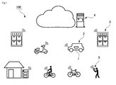
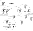
- FIG. 1 is an overall view of the battery management system.
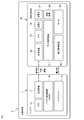
- FIG. 2 is a block diagram showing a functional configuration of the electric vehicle.
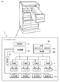
- FIG. 3 is a block diagram showing a functional configuration of the battery station.
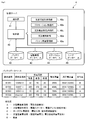
- FIG. 4 is a block diagram showing a functional configuration of the management server.
- FIG. 5 is a block diagram showing a functional configuration of the user terminal.
- FIG. 6 shows an example of information exchanged between the management server, the electric vehicle, the user terminal, and the battery station.
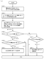
- FIG. 7 is a flowchart illustrating an example of the charge control information generation process in the management server.
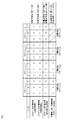
- FIG. 8 is a score table schematically showing an example of the charge control information generation process.
- FIG. 8 is a score table schematically showing an example of the charge control information generation process.
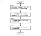
- FIG. 9 is a flowchart showing the details of the process (step 1) for evaluating the possibility of battery replacement according to the usage status of the electric vehicle.
- FIG. 10 schematically shows an example of a method for evaluating the possibility of battery replacement according to the usage status of the electric vehicle.
- FIG. 1 is an overall view showing an outline of the battery management system 100.
- a battery management system 100 includes a plurality of electric vehicles 2 equipped with a replaceable battery 1, a plurality of battery stations 3 for charging a replacement battery 1, and management of the entire system.
- a user terminal 5 owned by the user of the electric vehicle 2.
- the electric vehicle 2, the battery station 3, the management server 4, and the user terminal 5 can transmit and receive information to and from each other by short-range wireless communication such as the Internet or Bluetooth (registered trademark).
- the electric vehicle 2, the battery station 3, and the user terminal 5 are respectively connected to the management server 4 via the Internet.
- the user terminal 5 can perform short-range wireless communication with the electric vehicle 2 and the battery station 3.
- the battery 1 itself has a network communication function and a short-range wireless communication function, and the battery 1 can directly communicate with the electric vehicle 2, the battery station 3, the management server 4, and the user terminal 5.
- the electric vehicle 2 runs by driving a motor with electric power supplied from one or a plurality of batteries 1 mounted on the vehicle.
- Examples of the electric vehicle 2 are an electric vehicle (electric four-wheeled vehicle), an electric three-wheeled vehicle, an electric scooter (electric two-wheeled vehicle), and an electric bicycle.
- the electric vehicle 2 stops at a nearby battery station 3.
- a plurality of batteries 1 are stored and charged.
- the user of the electric vehicle 2 takes out the required number of charged batteries 1 from the battery station 3 and replaces the consumed battery 1 mounted on the electric vehicle 2. Thereby, the electric vehicle 2 can continue running using the charged battery 1.
- the battery station 3 is loaded with the battery 1 having a low remaining battery level. Then, the battery station 3 receives power supply from a power supply such as a power network and starts charging the battery 1 loaded therein.
- the battery 1 is standardized and can be used in various types of electric vehicles 2.
- the same battery 1 can be used as a power source for an electric vehicle and an electric scooter.
- the output can be adjusted according to each vehicle type.
- the system of the present invention is applied particularly to a sharing service of the electric vehicle 2.
- the system of the present invention is suitable for a sharing service of a dockless electric vehicle. More specifically, in the dockless system, an electric vehicle 2 equipped with a replaceable battery 1 is parked at an arbitrary location, and the user can use the electric vehicle 2 freely.
- the electric vehicle 2 is connected to the management server 4 via the Internet, and the management server 4 knows all the current positions of the electric vehicle 2. For this reason, the management server 4 can also send guidance information on the parking place of the electric vehicle 2 to the user terminal 5 owned by the user. Further, the user can make a reservation for using the electric vehicle 2 via the user terminal 5.
- Each electric vehicle 2 is provided with a locking device, which is controlled by the management server 4.
- the user when the user finds the electric vehicle 2 desired to be used, the user operates the user terminal 5 to make a preliminary application to the management server 4 or a two-dimensional code (for example, The QR code (registered trademark) is read by the user terminal 5 and the identification information of the vehicle is transmitted to the management server 4, or the user terminal 5 and the electric vehicle 2 perform short-range wireless communication to perform identification information from the vehicle. , And transmits the information to the management server 4 to the management server 4.
- the management server 4 performs an authentication process on the user who has applied for use of the electric vehicle 2, and when determining that the user has the authority to use the vehicle, unlocks the locking device of the electric vehicle 2 specified by the user. Lock. Thereby, the user can get on the specified electric vehicle 2 and move.
- a locking device is also provided in the battery storage room of each battery station 3, and the locking device is controlled by the management server 4. For this reason, when using the battery in the battery station 3, the user operates the user terminal 5 to make an advance application to the management server 4 or uses a two-dimensional code (for example, QR code) provided in the battery station 3. Code (registered trademark)) is read by the user terminal 5 and the identification information of the battery is transmitted to the management server 4, or the user terminal 5 and the battery station 3 perform short-range wireless communication to obtain the identification information from the station. Information about the battery station 3 desired to be used is transmitted to the management server 4 by acquiring and transmitting the acquired information to the management server 4.
- QR code for example, QR code
- the management server 4 performs an authentication process for the user who has applied for use of the battery station 3, and locks the empty battery storage room of the battery station 3 when determining that the user has the authority to use the battery station 3. Unlock the device.
- the consumed battery taken out of the electric vehicle 2 is stored in the empty battery storage room of the battery station 3, and charging is started based on the control from the management server 4.
- the charged battery can be taken out from the battery storage room of the battery station 3 and mounted on the electric vehicle 2.
- the stored battery 1 is stored in the battery station 3 and then the charged battery 1 can be taken out from the battery station 3.
- the present invention is not limited to this, and the charged battery 1 can be stored in the battery station 3. After being taken out of the battery station 3, the consumed battery 1 may be stored in the battery station 3.
- FIG. 2 is a block diagram showing the configuration of the electric vehicle 2 on which the battery 1 is mounted.
- the electric vehicle 2 mainly includes a replaceable battery 1 and a vehicle control unit 20.
- the vehicle control unit 20 is connected to the battery 1 via a power line, and receives power supplied from the battery 1 to drive the motor 24.
- the number of batteries 1 mounted on the vehicle increases or decreases depending on the type of the electric vehicle 2. That is, the number of batteries 1 mounted on the electric vehicle 2 may be one or more.
- an identification number (ID) is assigned to each of the batteries 1 used in the present system.
- the identification number (ID) of each battery 1 is stored in a battery database 42 of the management server 4 to be described later and is centrally managed.
- the battery 1 mainly includes a battery control device (BMS: Battery Management System) 10, a communication device 11, a GPS (Global Positioning System) 12, and a battery cell 13.
- BMS Battery Management System
- GPS Global Positioning System
- the battery control device 10 is mainly composed of an integrated circuit and various sensors.
- the battery control device 10 controls one or a plurality of battery cells 13 and can measure and calculate battery charge information including a remaining battery amount and the number of times of charging.
- the battery charge information acquired by the battery control device 10 includes, in addition to the identification number (ID) and the remaining battery charge, the number of times of charge, battery voltage, current, temperature, full charge capacity, and the like. Is also good. Note that, in the type of the battery 1 or the embodiment, it is not always necessary to provide the battery 1 with the battery control device 10.
- the communication device 11 of the battery 1 has a communication function of communicating the battery charge information acquired by the battery control device 10 to the outside. That is, the battery charge information such as the remaining battery level obtained from the battery control device 10 is stored in the vehicle control unit 20 by wire communication (such as CAN) or short-range wireless communication (such as Bluetooth (registered trademark)). It is preferably transmitted to the meter 27, the detector 32 mounted on the battery station 3, and the like.
- the communication device 11 of the battery 1 can perform two-way communication with the management server 4 via a communication network such as the Internet. That is, the communication device 11 can transmit the battery information acquired by the battery control device 10 to the management server 4 or can receive information from the management server 4. Further, the communication device 11 of the battery 1 may transmit information to the user terminal 5 owned by the user by short-range wireless communication. It should be noted that it is not necessary to provide the communication device 11 in the battery 1 according to the type or the embodiment of the battery 1.
- the GPS 12 is a device for measuring the current position of the battery 1 and obtaining information for specifying the current position.
- the GPS 12 measures the time required to receive each radio wave based on the information on the radio wave transmission time included in the radio waves transmitted from a plurality of GPS satellites, and outputs the time information indicating the time to the battery control device 10. To send to. It is preferable that the position information of the battery 1 acquired by the GPS 12 be transmitted to the management server 4 via the communication device 11. Note that, for example, in an embodiment in which the GPS 23 is provided in the vehicle control unit 20, it is not always necessary to provide the GPS 12 in the battery 1. Further, when the battery 1 is paired with the user terminal 5 by short-range wireless communication, the position information of the battery 1 can be acquired using the GPS 53 of the user terminal 5. It is not necessary to provide.
- a known secondary battery such as a rechargeable nickel-metal hydride battery or a lithium ion battery can be used for the battery cell 13.
- the vehicle control unit 20 includes an electronic control device 21, a communication device 22, a GPS 23, a motor 24, a power control device 25, a speedometer 26, a fuel gauge 27, and a locking device 28.
- the electronic control unit 21 controls each of the components 22 to 28 constituting the vehicle control unit 20.
- the electronic control unit 21 can be realized by a processor such as a CPU.
- the electronic control unit 21 includes, for example, battery information including the remaining battery level of the battery 1 acquired by the fuel gauge 27, current position information of the own vehicle acquired by the GPS 23, and the own vehicle measured by the speedometer 26. Can be obtained as appropriate. Further, the electronic control unit 21 can perform arithmetic processing on information obtained from various devices and transmit the information to the management server 4 via the communication device 22.
- the electronic control device 21 controls unlocking and locking of the locking device 28 based on control information from the management server 4.
- the communication device 22 can perform two-way communication with the management server 4 via a communication network such as the Internet. That is, the communication device 22 can transmit information processed by the electronic control device 21 to the management server 4 or receive information from the management server 4.
- the communication device 22 may be connected to the communication device 11 of the battery 1 by wire or wirelessly. That is, the communication device 22 can transmit the battery information acquired by the battery control device 10 to the management server 4 or receive the information from the management server 4. Further, the communication device 22 may transmit information to the user terminal 5 owned by the user by short-range wireless communication.
- the battery 1 is provided with a communication device 11, and the information processed by the electronic control device 21 of the electric vehicle 2 is bidirectionally transmitted to the management server 4 by the communication device 11 of the battery 1 via a communication network such as the Internet.
- the communication device 22 does not necessarily need to be provided in the vehicle control unit 20. Further, when the electric vehicle 2 is paired with the user terminal 5 by short-range wireless communication, information can be exchanged between the electric vehicle 2 and the management server 4 via the user terminal 5.
- the GPS 23 is a device for measuring the current position of the electric vehicle 2 and obtaining information for specifying the current position.
- the GPS 23 of the vehicle control unit 20 measures the time required to receive each radio wave based on the information of the radio wave transmission time included in the radio waves transmitted from a plurality of GPS satellites. Then, time information indicating the time is sent to the electronic control unit 21. Note that, in the embodiment in which the GPS 1 is provided in the battery 1, the GPS 23 does not necessarily need to be provided in the vehicle control unit 20.
- the position information of the electric vehicle 2 can be acquired using the GPS 53 of the user terminal 5. There is no need to provide the GPS 23 in the GPS 2.
- the motor 24 converts the electric power obtained from the battery 1 through the power control device 25 into a rotation output, and transmits the rotation output to the power transmission mechanism.
- the output from the motor 24 is transmitted to the wheels via the power transmission mechanism, so that the electric vehicle 2 runs.
- the power control device 25 has a function of controlling the power supplied from the battery cell 13 of the battery 1 and transmitting the power to the motor 24.
- the speedometer 26 is an instrument that calculates the instantaneous traveling speed of the electric vehicle 2 based on the rotation speed of the motor 24 or the power transmission mechanism or the position information acquisition device (GPS) 23. Note that, in the type or the embodiment of the electric vehicle 2, it is not always necessary to provide the speedometer 26 in the electric vehicle 2.
- the fuel gauge 27 acquires battery charging information including the identification number of the battery 1 and the remaining battery power.
- the fuel gauge 27 may acquire the battery charge information from the battery control device 10 included in the battery 1, or may communicate the identification number of the battery 1, the remaining battery capacity, and the like when the battery 1 is connected by wire communication (CAN). ) Or wireless communication (such as Bluetooth (registered trademark)).
- the battery charge information obtained by the fuel gauge 27 is output to the electronic control device 21. Note that, in the type or the embodiment of the electric vehicle 2, it is not always necessary to provide the fuel gauge 2 in the electric vehicle 2.
- the locking device 28 has a locking mechanism for substantially preventing the electric vehicle 2 from traveling.
- the locking device 28 may lock the tire of the electric vehicle 2 or lock the steering wheel. Further, the locking device 28 may electronically turn the electric vehicle 2 on or off. Further, the locking device 28 may lock the battery 1 and the electric vehicle 2 at the same time, or may lock them separately.
- the unlocking of the locking device 20 is preferably performed automatically by the electronic control device 21 based on control information from the management server 4. On the other hand, the locking of the locking device 28 may be automatically performed by the electronic control device 21 based on control information from the management server 4 or may be manually performed by the user.
- FIG. 3 is a block diagram showing a configuration of the battery station 3.
- the battery station 3 mainly includes a control device 30, a plurality of chargers 31, a detector 32, a communication device 33, a power supply 34, and a plurality of locking devices 35.
- the battery 1 can be loaded into each of the plurality of chargers 31.
- the charger 31 loaded with the battery 1 receives power supply from the power supply 34 and charges the battery 1 under the control of the controller 30.
- the control device 30 of the battery station 3 is connected to a plurality of chargers 31, detectors 32, communication devices 33, and locking devices 35. Therefore, the control device 30 can control the charging speed of the battery 1 by the charger 31 based on the control information received from the management server 4 via the communication device 33. Further, the control device 30 can process the detection information acquired by the detector 32 from the battery 1 and transmit the processed information to the management server 4 via the communication device 33. Further, the control device 30 can control whether or not the battery 1 can be taken out by unlocking or locking the locking device 35 provided for each storage room of the battery 1.
- the charger 31 is a device that is electrically connected to the battery 1 and performs a charging operation on the battery 1 by receiving power supply from the power supply 34.
- the charger 31 charges the battery 1 by, for example, a constant current and constant voltage method (CC-CV method).
- CC-CV method constant current and constant voltage method
- charging is performed at a constant current value from the beginning of charging, and when the voltage of the battery reaches a predetermined value as charging proceeds, the voltage is maintained.
- This is a charging method in which the charging current value is continuously reduced while continuously changing the charging current.
- the charger 31 can vary the charging speed of the battery 1 according to a control signal from the control device 30. For example, it is preferable that the charging rate of the charger 31 can be changed in at least two stages: normal charging in which charging is performed at a normal speed, and high-speed charging in which charging is performed at a higher speed than normal charging.
- the charger 31 may be capable of performing low-speed charging in which charging is performed at a lower speed than normal charging, in addition to normal charging and high-speed charging.
- the charging speed and the charging current value have a substantially directly proportional relationship in a battery remaining amount range where the charging current value is constant.
- the charging speed of the battery 1 can be freely adjusted.
- the battery 1 has an upper limit for a charging speed and a charging current value mainly from the viewpoint of safety and durability. For this reason, charging that is closer to the upper limit of the charging speed and charging current value is fast charging, charging that is closer to the lowering of the charging speed and charging current value is low charging, and charging that is performed using the current value between the high speed charging and the low speed charging is normally performed. Just charge it. In other words, charging performed at a standard rate within a certain range is called normal charging, charging faster than the normal charging range is called fast charging, and charging lower than the normal charging range is called slow charging. be able to.
- the detector 32 is a device for acquiring battery charge information including an identification number and a remaining battery level from the battery 1 in a charged state.
- the detector 32 may acquire the battery charge information from the battery control device 10 provided in the battery 1, or may communicate the identification number of the battery 1 and the remaining amount of the battery 1 by wire communication when the battery 1 is connected.
- the detection and measurement may be performed directly via CAN or the like or wireless communication (such as Bluetooth (registered trademark)).
- the remaining battery level of the battery 1 is obtained by, for example, measuring the charge / discharge current value of the battery 1 by the battery control device 10 and subtracting the amount of electricity obtained by integrating the currents from the remaining battery level in a fully charged state. Can be detected.
- the battery charge information detected by the detector 32 is sent to the control device 30.
- the communication device 33 is a device for the battery station 3 to perform two-way communication with the management server 4 via a communication network.
- the communication device 33 can transmit information processed by the control device 30 to the management server 4 or receive information from the management server 4.
- short-range wireless communication can be performed between the communication device 33 of the battery station 3 and the communication device 11 of the battery 1.
- a known power supply can be used as long as it can supply power to the charger 31.
- renewable energy obtained by the natural energy generator 34a may be used as the power supply 34.
- the natural energy generator 34a are a solar power generator, a solar thermal power generator, a wind power generator, and the like.
- the renewable energy generator 34a is preferably installed near the battery station 3. That is, the natural energy generator 34a may be mounted on the battery station 3 or may be arranged near the battery station 3.
- the battery station 3 may receive power from a renewable energy generator 34a owned by a power company via a power network.
- commercial power supplied from a power network 34b may be used as the power source 34.
- the power source 34 can use both renewable energy and commercial power.
- the electric power stored in the battery 1 can be sold to the outside via the battery station 3.
- the battery station 3 can sell the power stored in the battery 1 to a power company, a company, a general home, or the like via a power network.
- the power stored in the battery 1 can be sold to the user by lending or replacing the battery 1 loaded in the battery station 3.
- the locking device 35 has a locking mechanism for substantially preventing each battery 1 from being removed from the battery station 3.
- the locking device 35 is provided for each of the batteries 1 and performs locking or unlocking for each battery 1.
- the locking device 35 may lock the battery 1 itself to the battery station 3 or lock a lid that opens and closes a storage room of the battery 1.
- the unlocking of the locking device 35 is automatically performed by the control device 30 based on the control information from the management server 4.
- locking of the locking device 35 may be automatically performed by the control device 30 based on control information from the management server 4 or may be manually performed by a user.
- FIG. 4 is a block diagram showing the configuration of the management server 4.
- the management server 4 has a control unit 40, a communication unit 41, a battery database 42, an electric vehicle database 43, a station database 44, and a user database 45.
- the management server 4 has a function of controlling the present system by centrally managing information on the battery 1, the electric vehicle 2, the battery station 3, and the user.
- the management server 4 may execute these functions by one server device, or may execute these functions by a plurality of server devices.
- the control unit 40 of the management server 4 reads a program stored in the main memory, and performs a predetermined arithmetic process according to the read program.
- the control unit 40 of the management server 4 is connected to the communication unit 41 and various databases 42 to 45.
- the control unit 40 records information received from the battery 1, the electric vehicle 2, the battery station 3, and the user terminal 5 via the communication unit 41 in various databases 42 to 45. Further, the control unit 40 can generate a control signal for the electric vehicle 2 and the battery station 3 based on the information recorded in the various databases 42 to 45, and transmit the control signal via the communication unit 41.
- the control unit 40 is configured by a processor such as a CPU.
- the communication unit 41 is a device that allows the management server 4 to perform bidirectional communication with each of the battery 1, the electric vehicle 2, the battery station 3, and the user terminal 5 via a communication network. For example, the communication unit 41 transmits the control signal generated by the control unit 40 to the electric vehicle 2 and the battery station 3. The communication unit 41 can receive various information transmitted from the battery 1, the electric vehicle 2, the battery station 3, and the user 5.
- the battery database 42 is a storage unit for recording management information of each of the plurality of batteries 1 used in the present system.
- FIG. 4 shows an example of the data structure of the battery database 42.
- the battery database 42 stores various management information in association with the identification number (battery ID) of the battery 1 as key information.
- the management information of the battery 1 includes, for example, information on the current location of the battery, the number of times of charging, the remaining amount of the battery, the full charge capacity, and the degree of deterioration.
- the management server 4 can more accurately grasp the degree of deterioration of the battery from such information. . That is, the degree of deterioration of the battery can be more accurately predicted by comparing it with statistical data of a large number of batteries of the same type in the past, in addition to the number of times of charging and the full charge capacity of the battery alone.
- the identification number of the electric vehicle 2 in which the battery 1 is stored (vehicle ID), the identification number of the battery station 3 (station ID), and the like are recorded.
- the current position information (latitude and longitude information) received from the battery 1 by the management server 4 may be recorded.
- the electric vehicle 2 or the battery station 3 can store a plurality of batteries
- the information on the current location of the battery is stored in any of the plurality of storage locations of the vehicle 2 or the battery station 3. Is preferably information indicating whether or not is stored. Accordingly, when the battery station 3 can store a plurality of batteries 1, the management server 4 can recognize which storage room of the battery station 3 stores which battery 1.
- the identification number with an initial “V” is the identification number of the electric vehicle
- the identification number with the initial “S” is the identification number of the battery station.
- the numbers after “-” (hyphen) are room numbers of storage rooms of the electric vehicle or the battery station.
- the information on the number of times the battery has been charged information on the number of times the battery has been stored in the battery station 3 may be recorded, or the number of times the battery has been fully charged may be recorded, or It is also possible to record the number of times that the remaining amount of the battery after charging the battery is equal to or more than the specified numerical value or ratio.
- the method of obtaining the number of times of charging of the battery is not limited to the method described above, and other known methods can be employed.
- the information on the number of times of charging of the battery is recorded separately for each charging speed, such as the number of times of high-speed charging, the number of times of normal charging, and the number of times of low-speed charging. Is preferred. By counting the number of times of charging for each charging speed, the accuracy of calculating the degree of deterioration of the battery can be improved.
- the battery charge information including the battery identification number and the remaining battery level
- the battery charge information is always updated to the latest one.
- the rated full charge capacity and the full charge capacity of the battery are recorded.
- the rated full charge capacity is shown in parentheses.
- the battery control device 10 may measure and calculate the full charge capacity of the battery 1.
- the battery 1 does not include the battery control device 10 or when the battery control device 10 does not actually measure and calculate the full charge capacity even when the battery 1 includes the battery control device 10.
- Means that the rated full charge capacity before the start of use of the battery (when the battery is new) and the full charge capacity corrected by the control unit 40 in consideration of the deterioration of the battery are recorded in the battery database 42.
- the value of the full charge capacity decreases as the number of times the battery is used increases.
- the full charge capacity is preferably a value obtained by correcting the rated full charge capacity based on the number of times of high-speed charge, the number of times of normal charge, and the number of times of low-speed charge.
- high-speed charging may deteriorate the battery more than normal charging
- normal charging may deteriorate the battery more than low-speed charging. Therefore, in this case, it is more preferable to calculate the full charge capacity by changing the weighting of the degree of influence on the deterioration of the battery according to the high-speed charge, the normal charge, and the low-speed charge.
- the number of times of high-speed charging, normal charging, and low-speed charging of each battery is recorded in the battery database 42, and the recorded number of times of charging is compared with past statistical data, so that the full charge capacity can be more accurately determined. Can be guessed.
- the calculation of the above-described full charge capacity is performed by the control unit 40 based on information on the number of times of charge recorded in the battery database 42 and information on the rated full charge capacity.
- the method for obtaining the full charge capacity of the battery is not limited to the above method, and any other known method can be employed.
- the full charge capacity may be obtained by sequentially recording the electric resistance value when the battery 1 is charged.
- a memory other than the battery control device 10 for sequentially storing the full charge capacity in the battery 1 itself can be mounted.
- the control unit 40 calculates information on the degree of deterioration of the battery based on information recorded in the battery database 42.
- the degree of deterioration may be ranked in five stages from A (new) to E (old).
- the deterioration degree A means that the battery is new or close to it
- the deterioration degree E means that the battery needs to be discarded.
- the control unit 40 compares the full charge capacities, and can determine the degree of reduction from the rated full charge capacity to the actual full charge capacity as the degree of deterioration.
- the full charge capacity actually measured and calculated from a single battery by the battery control device 10 or the like may vary or be low in accuracy depending on an external environment or a use load.
- the degree of deterioration corrected based on the number of times of high-speed charging, the number of times of normal charging, and the number of times of low-speed charging.
- the number of times of high-speed charging, normal charging, and low-speed charging of each battery is recorded in the battery database 42, and the degree of deterioration is more accurately estimated by comparing the recording of the number of times of charging with past statistical data. can do.
- the method for determining the degree of deterioration of the battery is not limited to the method described above, and other known methods can be employed.
- the category of the usable electric vehicle 2 and other electric equipment is determined according to the degree of deterioration of the battery 1.
- the electric vehicles 2 are classified into large electric vehicles such as electric vehicles and small electric vehicles such as electric scooters and electric assist bicycles.
- Other electric devices are classified into portable power sources such as power tools and outdoor lighting devices, and stationary type storage batteries such as home storage batteries and power system storage batteries. Then, according to the degree of deterioration of each battery 1, the management server 4 determines which category of the electric vehicle or other electric device is used.
- a battery with a deterioration degree A is used for a power supply for a large electric vehicle
- a battery with a deterioration degree B is used for a power supply for a small electric vehicle
- a battery with a deterioration degree C is used for a portable power supply
- a battery with a deterioration degree D is used as a power source for stationary storage batteries.
- the management server 4 manages the categories of the electric vehicles and the like in which the batteries 1 can be used according to the degree of deterioration of each battery 1.
- the management server 4 may control each battery 1, each electric vehicle 2, and each electric device so that electric power is not supplied from the battery 1 to the electric vehicles 2 and electric devices of different categories. .
- the management server 4 can also control the locked state of the lid of the battery storage room of the battery station 3 so that the user of the electric vehicle 2 or the electric device cannot receive the batteries 1 of different categories. In this way, each battery can be used for an optimum use according to the degree of deterioration of the battery.
- an identification number (vehicle ID), a current position of the vehicle, a vehicle type, a battery use history, and the like are recorded in association with each of the plurality of electric vehicles 2 included in the present system.
- the information on the vehicle type includes information on the type of the electric vehicle 2, weight, fuel efficiency, model year, or a category related to the use of the battery 1.
- the use history of the battery includes the identification number (ID) of the battery used in the electric vehicle 2 and the identification number (ID) of the battery station that has obtained the battery.
- an identification number (station ID), a location, a battery use history, a battery charge history, and the like are recorded in association with each of a plurality of battery stations 3 included in the present system.
- the battery usage history includes information such as the number of times the battery 1 has been taken out from the battery station 3, date, date and time, weather, and the identification number of the battery 3 taken out.
- the charge history of the battery includes information such as the identification number of the battery charged in the battery station.
- the user database 45 includes, for each user of the present system, an identification number (user ID), a password, a name, a contact address, account information (or credit card information) for paying a usage fee, and an electric vehicle that can be used by the user. It is preferable that the vehicle type and the individual identification number of the user terminal 5 owned by the user are recorded in association with each other.
- the management server 4 acquires the current position information from the user terminal 5, the current position information can be recorded in the user database 45 as needed.
- the user database 45 determines whether or not the user has the authority to use the electric vehicle 2 in the management server 4 when the user transmits the application to start use of the electric vehicle 2 to the management server 4, It is referred to when performing authentication processing of whether or not the user has the payment ability.
- the control unit 40 of the management server 4 includes functions such as an exchangeability evaluation unit 40a, a promotion transmission unit 40b, a charge / discharge necessity evaluation unit 40c, a charge / discharge control unit 40d, and a battery use management unit 40e. It is preferred to have a part.
- Each of these functional units 40a to 40e functions when the control unit 40 reads a program stored in the main memory and executes the read program. The details of these functional units 40a to 40e will be described later.
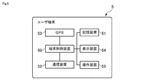
- FIG. 5 is a block diagram showing the configuration of the user terminal 5.
- the user terminal 5 is a portable terminal such as a smartphone or a tablet terminal, and is owned by a user who wants to use the electric vehicle 2.
- the user terminal 5 includes a terminal control device 50, a storage device 51, a communication device 52, a GPS 53, a display device 54, and an operation device 55.
- a terminal control device 50 a storage device 51
- a communication device 52 a GPS 53
- a display device 54 a display device 54
- an operation device 55 an example of the function of the user terminal 5 is given, but the user terminal 5 may also have a function normally provided in a known smartphone or the like.
- the terminal control device 50 of the user terminal 5 performs a process of controlling other elements 51 to 55 provided in the user terminal 5.
- a processor such as a CPU can be used as the terminal control device 50.
- the terminal control device 50 reads an application program (computer program) stored in the storage device 51 and controls other elements according to the application program. Further, the terminal control device 50 can appropriately write and read the operation result according to the application program in the storage device 51.
- the storage device 51 of the user terminal 5 is an element for storing information used for arithmetic processing and the like in the terminal control device 50. More specifically, the storage device 51 stores an application program that causes a general-purpose portable information communication terminal to function as the user terminal 5 in the battery management system 100 according to the present invention. This application program may be downloaded to the user terminal 5 via the Internet, or may be preinstalled on the user terminal 5. The storage device 51 may store other programs in addition to the application program for the present system. When an application program for the present system is started by an instruction from a user, processing according to the program is executed. The storage device 51 stores identification information unique to the user, individual identification information unique to the user terminal, and the like.
- the storage function of the storage device 51 can be realized by a nonvolatile memory such as an HDD and an SDD. Further, the storage device 51 may have a function as a memory for writing or reading the progress of the arithmetic processing by the terminal control device 50 or the like.
- the memory function of the storage device 51 can be realized by a volatile memory such as a RAM or a DRAM.
- the communication device 52 of the user terminal 5 is a device for exchanging information with the management server 4 via a communication network such as the Internet.
- the communication device 52 can transmit various information to the management server 4 or receive various information from the management server 4 under the control of the terminal control device 50.
- the communication device 52 of the user terminal 5 may have a function of enabling short-range wireless communication between the battery 1, the electric vehicle 2, and the battery station 3.
- the GPS 53 is a device for measuring the current position of the user terminal 5 and obtaining information for specifying the current position.
- the GPS 53 of the user terminal 5 measures the time required to receive each radio wave based on the information of the radio wave transmission time included in the radio waves transmitted from a plurality of GPS satellites, like the GPS 12 of the battery 1 and the like. Then, time information indicating the time is transmitted to the terminal control device 50.
- the display device 54 is a display that displays a predetermined image or the like under the control of the terminal control device 50.
- a known display such as a liquid crystal display or an organic EL may be used.
- the operation device 55 is an element for receiving information input to the user terminal 5 from the user.
- the information input via the operation device 55 is transmitted to the terminal control device 50.
- various input devices used in a known information communication terminal can be adopted. Examples of the operation device 55 include, but are not limited to, a touch panel, buttons, a cursor, a microphone, a keyboard, and a mouse. Further, a touch panel display may be configured by overlapping a touch panel on the display.
- FIG. 6 shows an embodiment in which the system of the present invention is applied to a sharing service of the electric vehicle 2.
- the electric vehicle 2 acquires the current position information with the GPS 23 and periodically transmits the acquired position information to the management server 4 together with its own vehicle ID. Further, the electric vehicle 2 measures the remaining battery level of the battery 1 mounted therein, and periodically transmits the measured remaining battery level to the management server 4 together with the battery ID. For this reason, the management server 4 knows the current position and the remaining amount of the battery 1 for each electric vehicle 2.
- the user transmits the current position information acquired by the GPS 53 of the user terminal 5 to the management server 4, and from the management server 4, the position of the electric vehicle 2 near the user's current position and the electric vehicle Vehicle information such as the type of the vehicle 2 or the remaining amount of the battery 1 mounted on the electric vehicle 2 can be obtained.
- the vehicle information of the electric vehicle 2 near the current position of the user is displayed on the display device 54 of the user terminal 5.
- the user terminal 5 reads, for example, a two-dimensional code (such as a QR code (registered trademark)) provided on the electric vehicle 2.
- the two-dimensional code of the electric vehicle 2 is obtained by encoding the vehicle ID of the electric vehicle 2 and the like, and the user terminal 5 can read the two-dimensional code to obtain the vehicle ID of the electric vehicle 2 that the user wants to ride.
- short-range wireless communication may be performed between the electric vehicle 2 and the user terminal 5, and the vehicle ID may be transmitted from the electric vehicle 2 to the user terminal 5.
- the electric vehicle 2 can also transmit remaining battery level information to the user terminal 5.
- the user When the user obtains the vehicle ID of the electric vehicle 2, the user transmits a vehicle use request from the user terminal 5 to the management server 4.
- the vehicle use request includes information such as the user's own user ID, the password of each user, and the vehicle ID of the electric vehicle 2 that wants to ride.
- the management server 4 When receiving the vehicle use request from the user terminal 5, the management server 4 performs an authentication process for confirming whether the user has the right to use the electric vehicle 2. For example, the management server 4 checks whether the password of the user who has made the use request is correct. If the user account has an expiration date, the management server 4 checks whether the expiration date has passed or if the credit card for paying the usage fee has expired. Good.
- the management server 4 checks whether the type of the electric vehicle 2 according to the use request is available to the user. . Further, when the use reservation of the electric vehicle 2 is possible, the management server 4 checks whether the electric vehicle 2 according to the use request of a certain user is not already reserved by another user. When the management server 4 determines that the user has the authority to use the electric vehicle 2 through these authentication processes, the management server 4 unlocks the electric vehicle 2 with the unlock information ( Unlock instruction). Thus, the locking device 28 of the electric vehicle 2 is unlocked, and the user can use the electric vehicle 2.
- Unlock instruction Unlock instruction
- the management server 4 transmits the unlock information to the user terminal 5 via the Internet, and the user terminal 5 transmits the unlock information to the electric vehicle 2.
- the unlock information may be transferred by short-range wireless communication.
- the user may transmit a use reservation of the electric vehicle 2 to the management server 4 in advance.
- the information on the vehicle use reservation includes the user's own user ID, the user's password, the vehicle ID of the electric vehicle 2 that he / she wants to board, and information on the use start reservation date and time and the scheduled end date and time of use. It may be.
- the management server 4 restricts the electric vehicle 2 reserved by a certain user from being used by another user until the use start reservation date and time.
- the electric vehicle 2 transmits the use start information to the management server 4.
- the use start information includes, for example, information on a use start place and a use start date and time. Further, it is preferable that the electric vehicle 2 periodically transmits the current position information to the management server 4 during the period of use by the user. As described above, since the electric vehicle 2 periodically transmits the current position information to the management server 4, the management server 4 can grasp the moving route of each electric vehicle 2.
- the electric vehicle 2 transmits the use end information to the management server 4.
- the use end information includes, for example, information on a use end place and a use end date and time.
- the user manually locks the locking device 28 of the electric vehicle 2 when the electric vehicle 2 ends.
- the locking device 28 is locked, the electric vehicle 2 transmits the locking information to the management server 4.
- the management server 4 can recognize that the use of the electric vehicle 2 has been completed and that the electric vehicle 2 has been locked. Note that the management server 4 can also control locking of the electric vehicle 2.
- the management server 4 determines that the electric vehicle 2 has not been locked for a certain period of time after the use of the electric vehicle 2 ends, the management server 4 transmits locking information (locking command) to the electric vehicle 2 and The vehicle 2 is locked. Further, for example, when there is a limit on the available time of the electric vehicle 2 in advance, the management server 4 first transmits the use end information to the user terminal 5 to notify the user that the use end time is approaching. After that, the management server 4 transmits the locking information to the electric vehicle 2 when it is confirmed that the user has got off the electric vehicle 2.
- the management server 4 transmits the lock information to the user terminal 5 via the Internet, and the user terminal 5 transmits the lock information to the electric vehicle 2.
- Locking information may be transferred by short-range wireless communication.
- the battery station 3 periodically transmits, to the management server 4, battery information including its own station ID and the battery ID and remaining battery level of each of the one or more batteries 1 stored therein.
- the battery information may include the number of times of charging the battery, the number of times of low-speed / normal / rapid charging, and the like.
- the management server 4 can grasp the remaining battery level and the degree of deterioration of each battery 1 in the battery station 3.
- the user transmits the current position information acquired by the GPS 53 of the user terminal 5 to the management server 4, so that the user is present near the user's current position from the management server 4.
- Station information of the battery station 3 can also be obtained.
- the station information includes position information on the battery station 3 and information on the battery 1 stored in the battery station 3.
- the information on the battery 1 preferably includes, for example, information on the remaining battery level of the battery 1 and the category of the vehicle in which the battery 1 can be used.
- information on the battery station 3 near the current position of the user is displayed on the display device 54 of the user terminal 5. Note that the user can naturally stop by the battery station 3 and replace the battery 1 without checking the position of the battery station 3 in advance or making a reservation in advance.
- the management server 4 can also transmit promotion information regarding battery replacement to the user terminal 5.
- the promotion information includes information on the battery station 3 to which the user wants to be guided, and information such as a privilege given to the user.
- the promotion information includes, for example, information on a store where the battery station 3 is installed, a coupon that can be used at the store, and the like.
- the promotion information includes points given to the user when the user replaces the battery at the battery station 3 pointed out by the management server 4 (having a monetary value available in the present system). (Points) may be included. As a result, it is possible to guide the user to the battery station 3 which is convenient for the system operator or to give the user motivation to perform battery replacement at the designated battery station 3.
- the user terminal 5 reads, for example, a two-dimensional code (a QR code (registered trademark)) provided at the battery station 3.
- a two-dimensional code a QR code (registered trademark)
- the two-dimensional code may be provided for each storage room of the battery station 3.
- the two-dimensional code of the battery station 3 is obtained by encoding the station ID of the battery station 3, the room number of the storage room storing the battery 1, and the like. Therefore, by reading the two-dimensional code by the user terminal 5, the ID of the battery station 3 or the storage room in which the battery 1 to be replaced is stored can be obtained.
- the battery station 3 instead of reading the two-dimensional code, for example, short-range wireless communication is performed between the battery station 3 and the user terminal 5, and the station ID and the storage room ID are transmitted from the battery station 3 to the user terminal 5. Is also good. At this time, the battery station 3 can also transmit remaining battery level information to the user terminal 5.
- the user transmits a battery replacement request from the user terminal 5 to the management server 4.
- the battery replacement request includes information such as the user's own user ID, the user's password, the vehicle ID of the electric vehicle 2 whose battery is desired to be replaced, the station ID of the battery station 3, and the ID of the storage room in which the battery 1 is stored. Is included.
- the management server 4 Upon receiving the battery replacement use request from the user terminal 5, the management server 4 performs an authentication process to confirm whether the user has the right to replace the battery at the battery station 3. For example, the management server 4 checks whether the password of the user who has made the exchange request is correct.
- the management server 4 can use the battery 1 stored in the battery station 3. Check that the correct category matches the electric vehicle for which the battery is to be replaced. Further, when the battery replacement can be reserved, the management server 4 confirms whether or not the battery 1 relating to the replacement request of a certain user has already been reserved for replacement by another user. If the management server 4 determines that the user has the authority to replace the battery 1 through these authentication processes, the management server 4 sends the unlock information (unlock information) of the locking device 35 to the battery station 3 via the Internet. Command).
- the locking device 35 of the battery 1 is unlocked, and the user can take out the charged battery 1 from the battery station 3.
- the management server 4 transmits the unlock information to the user terminal 5 via the Internet, and the user terminal 5 transmits the unlock information to the battery station 3.
- the unlock information may be transferred to the third device by short-range wireless communication.
- the user removes the consumed battery 1 from the electric vehicle 2 and attaches the charged battery 1 taken out from the battery station 3 to the electric vehicle 2.
- the user stores the consumed battery 1 removed from the electric vehicle 2 in the battery station 3.
- the battery station 3 transmits exchange completion information to the management server 4.
- the exchange completion information includes information on the charged battery 1 (battery ID and the like) passed to the user and information on the consumed battery 1 (battery ID and the like) received from the user.
- the battery station 3 charges the battery 1 under the control of the management server 4.
- the charge control information is transmitted from the management server 4 to the battery station 3.
- the charge control information includes a command for charging or discharging the battery 1 and a command relating to a charging / discharging speed.
- the battery station 3 controls the charging and discharging of each battery 1 and the speed thereof.
- the user manually locks the locking device 35 of the battery station 3.
- the battery station 3 transmits the locking information to the management server 4.
- the management server 4 can recognize that the replacement of the battery has been completed and that the battery station 3 has been locked.
- the management server 4 can also control locking of the battery station 3. For example, when the management server 4 determines that the electric vehicle 2 has not been locked for a certain period of time after the replacement of the battery 1 has been completed, the management server 4 transmits locking information (locking command) to the battery station 3 and Lock the storage room.
- the management server 4 transmits the lock information to the user terminal 5 via the Internet, and the user terminal 5 transmits the lock information to the battery station 3.
- Locking information may be transferred by short-range wireless communication.
- FIG. 7 shows a main flow of the charge control information generation process
- FIG. 8 shows an example of a score table in which the charge speed of each battery 1 is quantitatively determined according to the flow of FIG. 9 shows a sub-flow of step 1 shown in FIG. 7, and
- FIG. 10 schematically shows a positional relationship between the electric vehicle 2 and the battery station 3.
- the exchangeability evaluation unit 40a of the management server 4 quantitatively evaluates the exchangeability of each battery according to the use status of a plurality of electric vehicles included in the present system.
- the usage status of the electric vehicle includes at least information on the position of each electric vehicle 2 and information on the remaining amount of the battery 1 mounted on each electric vehicle 2.
- the position information of the electric vehicle 2 is position information at a point where the use has been started by the user. For example, when the user starts using the electric vehicle 2 equipped with the battery 1 with a low remaining battery, the battery stored in the battery station 3 near the electric vehicle 2 is evaluated as having high exchangeability. You.
- the exchangeability evaluation unit 40a determines the limit point of the operable range of the electric vehicle 2 based on the position information at the start of use of the electric vehicle 2 and the remaining amount of the battery 1 mounted thereon. It may be estimated. Then, the exchangeability evaluation unit 40a evaluates that the battery 1 stored in the battery station 3 near the limit point of the travelable range of the electric vehicle 2 has a high exchangeability.
- the replaceability evaluating unit 40a may evaluate the replaceability of the battery 1 in each battery station 3 based on the position information and the remaining battery level of the electric vehicle 2 at the time of starting use by the user. As a result, the charging speed and the like of the battery 1 can be controlled immediately after the user starts using the electric vehicle 2, so that the charging of the battery 1 is completed despite the user arriving at the battery station 3. Can be avoided.
- the exchangeability evaluation section 40a of the management server 4 further evaluates the exchangeability of each battery 1 according to the promotion information transmitted to the user from the promotion transmission section 40b (step 2).
- the promotion transmitting unit 40b of the management server 4 sends the management server to the user terminal 5 at a timing such as when the electric vehicle 2 starts, when the electric vehicle 2 runs, or when the use of the electric vehicle 2 ends. 4 transmits the promotion information for guiding to the battery station 3 designated.
- the promotion transmitting unit 40b may transmit the promotion information when receiving a vehicle use request or a vehicle use reservation, or a battery replacement request or a battery replacement reservation from the user terminal 5.
- the content of the promotion information is not particularly limited, but is preferably an advertisement for a store where the battery station 3 is installed, or other content that provides a benefit to the user.
- the promotion information may present a coupon, a point, or a provision of money to the user.
- the exchangeability evaluation unit 40a evaluates the exchangeability of each battery according to the content of such promotion information. For example, when promotion information including a valuable coupon or the like is transmitted to the user for the battery 1 in a certain battery station 3, the exchangeability evaluation unit 40a determines whether the exchangeability of the battery 1 is high. Evaluate as high. As described above, the exchangeability may be evaluated based on the high value of the promotion information.
- the following conditions can be considered as conditions for transmitting promotion information.
- ⁇ 1. When sending promotion information at the time of departure> 1a.
- the battery station 3 near the starting point of the electric vehicle 2 has a shortage of the charged battery 1 or sells (discharges) power in response to a request from an electric power market or a facility where the battery station is installed or in the vicinity thereof.
- the user wants to avoid replacing the battery at the battery station 3 near the starting point.
- promotion information is transmitted at the battery station 3 near the user's destination (passing point and arrival point) in order to encourage battery replacement.
- 1b At the battery station 3 near the destination of the user, the user wants to purchase (charge) power in response to a request from the power market or the facility where the battery station is installed or the vicinity thereof.
- promotion information is transmitted at the battery station 3 near the destination of the user in order to prompt battery replacement.
- 1c At the battery station 3 near the user's departure point, he wants to immediately start power purchase (charging) in response to a request from the power market or the facility where the battery station is installed or its vicinity. In this case, promotion information is transmitted at the battery station 3 near the departure point in order to encourage battery replacement.
- 1d At the destination of the user, there are few charged batteries 1 or electric vehicles 2 with a high remaining battery level. In this case, promotion information is transmitted at the battery station 3 near the departure point in order to encourage battery replacement. 1e.
- the battery station 3 at the passing point of the user is either short of the charged battery 1 or wants to sell (discharge) power in response to a request from the power market or the facility where the battery station is installed or in the vicinity thereof. , It is desired that the user does not replace the battery at the battery station 3 at the passing point. In this case, promotion information is transmitted at the battery station 3 near the user's destination (passing point and arrival point) in order to prompt battery replacement. 2b. At the battery station 3 near the user's destination, the user wants to purchase (charge) power in response to a request from the power market or the facility where the battery station is installed or the vicinity thereof. And while increasing the charging capacity of the battery station 3 near the destination.
- promotion information is transmitted at the battery station 3 near the user's destination (passing point and arrival point) in order to prompt battery replacement. 2c. It is desired to immediately start power purchase (charging) in response to a request from the power market at the battery station 3 at the passing point of the user. In this case, promotion information is transmitted in order to prompt the battery exchange at the battery station 3 at the passing point. 2d. There are few charged batteries 1 or vehicles with a high remaining battery level at the user's subsequent destinations. In this case, promotion information is transmitted in order to prompt the battery exchange at the battery station 3 at the passing point. 2e. After the first user has finished using the electric vehicle 2, if the second user who uses the electric vehicle 2 next has to replace the battery, inconvenience may be caused to the second user. It makes me feel. However, there is no replaceable battery 1 near the departure point or the arrival point of the first user. In this case, promotion information is transmitted to the first user in order to prompt the first user to replace the battery at the battery station 3 at the passing point.
- the charge / discharge necessity evaluation unit 40c of the management server 4 evaluates the necessity of charging / discharging each battery 1 based on the demand and supply in the power market or the facility where the battery station is installed or in the vicinity thereof (step). 3). Basically, when a power surplus (demand ⁇ supply) occurs in or near the power market or the facility where the battery station is installed, the battery 1 in the battery station 3 is charged (purchased). If there is a power shortage (demand> supply) at or near the power market or the facility where the battery station is installed, the power from the battery 1 of the battery station 3 to the power network or the facility where the battery station is installed or near the facility.
- a power surplus demand ⁇ supply
- the battery 1 in the battery station 3 is charged (purchased). If there is a power shortage (demand> supply) at or near the power market or the facility where the battery station is installed, the power from the battery 1 of the battery station 3 to the power network or the facility where the battery station is installed or near the facility.
- the charging / discharging necessity evaluating unit 40c evaluates the necessity of charging / discharging of each battery 1 so as to discharge (power sale). Further, in addition to the actual demand and supply of power, the demand and supply of power are predicted based on external factors such as time zone, weather, and temperature, and the charging and discharging of each battery 1 is performed based on the predicted value. May be evaluated.
- the charge / discharge necessity evaluation unit 40c can refer to, for example, the following information when evaluating the necessity of charging / discharging the battery 1. a. Actual or predicted supply and demand timing b. Actual or predicted electricity rates c. Actual or predicted CO 2 emissions d. Actual or projected carbon tax / carbon credit
- the table in FIG. 8 shows the scores of the exchangeability and the charge / discharge necessity of each battery evaluated based on the above steps 1 to 3.
- a plurality of batteries (batteries A to L) are stored in each of a plurality of battery stations (eg, stations 1 to 4).
- Step 1 the replaceability of each battery is evaluated in three stages of 0 to 2
- Step 2 the replaceability of each battery is evaluated in six stages of 0 to 5, and in Step 3, each battery is replaced.
- the necessity of charging is evaluated on three levels from 0 to 2
- the necessity of discharge is evaluated on six levels from 0 to -5.
- the sum of the evaluation values of steps 1 to 3 is defined as a charging priority (minimum 0 to maximum 9), and the charging speed of each battery is determined according to the charging priority.
- the charge / discharge control unit 40d of the management server 4 determines, for each battery station 3, whether each station is a charging target or a discharging target (Step 4).
- each battery station 3 cannot simultaneously charge and discharge a plurality of batteries 1 stored therein.
- the battery station 3 can control only whether or not each of the batteries 1 stored therein is charged or discharged, and charges a certain battery 1 and discharges another battery 1. Cannot be controlled.
- the charge / discharge control unit 40d determines whether to be charged or discharged for each battery station 3 based on the charge / discharge necessity evaluated in step 3. For example, in the table shown in FIG.
- the station 4 it is evaluated that the necessity of discharging the battery K and the battery L is high.
- the discharge necessity of the battery K and the battery L is “ ⁇ 5”, and their absolute values are greater than the absolute value of the charge necessity of the battery J “2”.
- the maximum value (absolute value) of a battery that needs to be charged and the maximum value (absolute value) of a battery that needs to be discharged are compared, and if the former exceeds the latter, the battery The entire station 3 is designated as a discharge target. For this reason, in step 4, the station 4 is determined to be a discharge target, and the other stations 1 to 3 are determined to be charged.
- the charge / discharge control unit 40d determines whether or not the charging priority of each battery 1 stored in the battery station 3 determined to be discharged is higher than a certain threshold (step 5). Only the battery 1 whose charging priority is higher than a certain threshold is to be charged. For example, in the examples shown in FIGS. 7 and 8, only batteries having a charge priority of 2 or more are recognized as objects to be charged. Specifically, only the batteries A, B, E, F, G, H, and I having the charge priority of 2 or more are to be charged, and the batteries C and D having the charge priority of 1 or less are to be charged. Excluded from The batteries C and D are not charged.
- the charging / discharging control unit 40d controls the charging speed of each battery 1 selected as a charging target based on the charging priority obtained from the evaluation values of Steps 1 to 3 (Step 6). For example, among the batteries A, B, E, F, G, H, and I to be charged, the charging priority of the battery G is “6”, which is the highest, and the charging priority of the battery F is “2”, which is the lowest. Has become. For this reason, the charge / discharge control unit 40 generates charge control information for each battery station 3 such that the battery G is charged fastest and the battery F is charged slowest among these batteries to be charged. .
- charge control information for each battery station 3 is generated so that each battery that has been recognized as a charge target is charged at a charge rate according to the charge priority.
- the management server 4 transmits the charge control information generated by the charge / discharge control unit 40d to each of the battery stations 3 to be charged.
- the battery station 3 performs charging while adjusting the charging speed of each battery 1 stored therein according to the charge control information received from the management server 4.
- the charge / discharge control unit 40d determines whether each battery 1 stored in the battery station 3 is a discharging target. (Step 7). For example, in the examples shown in FIGS. 7 and 8, among the batteries J, K, and L in the station 4, the battery J is not required to be discharged, and thus is excluded from the discharge target, and the batteries K, Since L needs to be discharged, it is determined that L is to be discharged. Note that the battery J is not charged or discharged.
- the charge / discharge control unit 40d controls the discharge speed of the battery 1 that has been identified as a discharge target based on the discharge necessity evaluated in step 3 (step 8). For example, since the discharge necessity of the batteries K and L is evaluated as “5”, the charging / discharging control unit 40d determines from the batteries K and L the power grid or the facility where the battery station is installed or the facility where the battery station is installed in accordance with the evaluation result. Discharge (power sale) in the vicinity. The charge / discharge control unit 40d generates discharge control information for the battery that needs to be discharged, and transmits this to the battery station 3 to be discharged. In accordance with the discharge control information received from the management server 4, the battery station 3 discharges to the power network or the facility where the battery station is installed or in the vicinity thereof while adjusting the charging speed of each battery 1 stored therein.
- the management server 4 determines or predicts which user will start using the electric vehicle 2 and when. (Step 1-1). For example, based on a vehicle use request or a vehicle use reservation received from the user terminal 5, the management server 4 determines whether the user who uses the sharing service, the electric vehicle 2 related to the user's use, and the start of use of the electric vehicle 2 Can be specified. In addition, the management server 4 may predict the future usage status of a specific user based on the usage history of the specific user, or may determine the future usage status of the entire user based on the usage history of an unspecified number of general users. It can also predict usage.
- the management server 4 predicts the moving range of the user who has boarded the electric vehicle 2 based on the specification or prediction in step 1-1, and determines the battery station 3 within the moving range (step 1). -2). For example, the management server 4 predicts a movable distance around the departure point from the departure point (starting point of use) of the electric vehicle 2 and the remaining amount of the battery 1 mounted on the electric vehicle 2, A circle having the movable distance as a radius is defined as a user's moving range. Further, the management server 4 periodically obtains position information from the electric vehicle 2, obtains a past movement route of the electric vehicle 2 based on the position information, and predicts a future movement direction from the movement route. Is also good.
- the management server 4 may predict the movement range of a specific user based on the usage history of the specific user, or predict the movement range of the entire user based on the usage history of an unspecified number of general users. You can also.
- the management server 4 evaluates the necessity of replacing the battery 1 mounted on the electric vehicle 2 used by the user (step 1-3).
- the necessity of replacing the battery 1 at the time when the user starts using the electric vehicle 2 (at the time of departure) is evaluated. For example, if the remaining battery level of the battery 1 of the electric vehicle 2 is small, the necessity of replacement is evaluated as high, and if the remaining battery level is large, the necessity of replacement is evaluated as low.
- the management server 4 may predict the battery consumption due to the movement from the movement range of the electric vehicle 2 predicted in step 1-2, and may predict the necessity of battery replacement based on the consumption.
- the management server 4 may predict the necessity of replacement of the battery 1 mounted on the electric vehicle 2 based on the usage history of a specific user, or based on the usage history of an unspecified number of general users. It is also possible to predict the necessity of battery replacement for the entire electric vehicle 2.
- the management server 4 evaluates the replaceability of each battery 1 in each battery station based on the results of the determination, prediction and evaluation of steps 1-1 to 1-3 (step 1-4). .
- the management server 4 predicts the moving range of the electric vehicle from the position at the start of use and the predicted moving direction of the electric vehicle for each electric vehicle. did.
- the management server 4 evaluated the necessity of battery replacement based on the remaining amount of the battery mounted on each electric vehicle. Under these assumptions, the management server 4 evaluates the replaceability of the battery in each battery station in step 1-4. In particular, it is preferable to evaluate the replaceability of each battery based on information at the time when the user starts using the electric vehicle.
- the replaceability of each battery station is evaluated in three stages from 0 to 2.
- the station 1 is within the predicted movement range of the vehicles A and B, and is located at the predicted movement destination of the vehicles A and B.
- the battery in the station 1 is highly likely to be exchanged, and is evaluated as having the exchangeability "2".
- the stations 2, 4, and 5 all belong to the predicted movement range of the vehicle A or the vehicle B. Therefore, these stations 2, 4, and 5 are evaluated as having exchangeability "1" because the exchangeability exists to a certain extent.
- the vehicle C is located near the station 6, the user has not yet boarded the vehicle C.
- the gender is evaluated as “0”. In this way, the exchangeability of each battery in the battery station is evaluated according to the situation at the start of use of the electric vehicle.
- FIG. 10 shows a simplified example of the evaluation of the replaceability of the battery, the replaceability of the battery is actually evaluated in consideration of more complicated conditions.
- the control unit 40 of the management server 4 has a battery use management unit 40e.
- the battery use management unit 40e basically determines and manages the use use of each battery according to the degree of deterioration of each battery. As described above, in the present embodiment, in accordance with the degree of deterioration of each battery, for a large electric vehicle (deterioration degree A), for a small electric vehicle (deterioration degree B), for a portable power supply (deterioration degree C), and for a stationary storage battery. The use of the battery is determined, such as the use (deterioration degree D).
- the battery use management unit 40e determines a category of an electric vehicle or another electric device that can use the battery based on the use of the battery.
- a battery for a large electric vehicle (deterioration degree A) is a battery dedicated to the electric vehicle category, and cannot be used as a power supply for a small electric vehicle, a portable power supply, or a stationary storage battery. Therefore, the battery use management unit 40e controls the locking device of the battery station storing the battery so that the battery for the large electric vehicle (deterioration degree A) cannot be used by a user other than the electric vehicle. Just fine. Alternatively, the battery use management unit 40e sends a control signal directly to the battery itself, and even if a battery for a large electric vehicle (deterioration degree A) is mounted on an electric vehicle other than the electric vehicle, the electric power is supplied to the vehicle. The battery may be controlled so as not to supply the vehicle to the vehicle.
- the battery use management unit 40e sends a control signal directly to the electric vehicle, and does not receive power from the battery when the battery for a large electric vehicle (deterioration degree A) is mounted on an electric vehicle other than the electric vehicle.
- the electric vehicle may be controlled as described above.
- the battery quantity of the deterioration degree B is relatively smaller than the battery quantity of the deterioration degree A based on the user demand
- the battery of the deterioration degree A is mainly used by the user.
- the battery usage management unit 40e determines the usage of the battery according to the degree of deterioration of each battery, and controls the battery station, the electric vehicle, and the battery itself so that the battery is used in the usage. Can be controlled.
- the charge rate or the discharge rate of the battery stored in the battery station is determined by evaluating the replaceability of each battery in accordance with the use situation of the electric vehicle.
- the battery may not be charged in time until the electric vehicle arrives at the battery station. In such a case, such a battery that cannot be clearly charged in time may be excluded from the charging target, or the possibility of replacing the battery may be excluded from the evaluation target.
- the present invention relates to a battery management system for an electric vehicle and the like.
- the system of the present invention can be used for a sharing service of an electric vehicle.
Abstract
Priority Applications (11)
| Application Number | Priority Date | Filing Date | Title |
|---|---|---|---|
| AU2019292101A AU2019292101B2 (en) | 2018-06-29 | 2019-06-26 | Battery management system |
| CN201980026543.1A CN112272909A (zh) | 2018-06-29 | 2019-06-26 | 电池管理系统 |
| KR1020207034412A KR102616027B1 (ko) | 2018-06-29 | 2019-06-26 | 배터리 관리 시스템 |
| CA3100184A CA3100184A1 (fr) | 2018-06-29 | 2019-06-26 | Systeme de gestion de batterie |
| SG11202011208WA SG11202011208WA (en) | 2018-06-29 | 2019-06-26 | Battery management system |
| MX2020012105A MX2020012105A (es) | 2018-06-29 | 2019-06-26 | Sistema de gestion de bateria. |
| EP19825984.8A EP3817179A4 (fr) | 2018-06-29 | 2019-06-26 | Système de gestion de batterie |
| US17/020,830 US11724615B2 (en) | 2018-06-29 | 2020-09-15 | Battery management system |
| PH12020551914A PH12020551914A1 (en) | 2018-06-29 | 2020-11-10 | Battery management system |
| US18/198,843 US11865941B2 (en) | 2018-06-29 | 2023-05-18 | Battery management system |
| AU2023219831A AU2023219831A1 (en) | 2018-06-29 | 2023-08-22 | Battery management system |
Applications Claiming Priority (2)
| Application Number | Priority Date | Filing Date | Title |
|---|---|---|---|
| JP2018124979A JP6564502B1 (ja) | 2018-06-29 | 2018-06-29 | バッテリ管理システム |
| JP2018-124979 | 2018-06-29 |
Related Child Applications (1)
| Application Number | Title | Priority Date | Filing Date |
|---|---|---|---|
| US17/020,830 Continuation US11724615B2 (en) | 2018-06-29 | 2020-09-15 | Battery management system |
Publications (1)
| Publication Number | Publication Date |
|---|---|
| WO2020004509A1 true WO2020004509A1 (fr) | 2020-01-02 |
Family
ID=67692203
Family Applications (1)
| Application Number | Title | Priority Date | Filing Date |
|---|---|---|---|
| PCT/JP2019/025487 WO2020004509A1 (fr) | 2018-06-29 | 2019-06-26 | Système de gestion de batterie |
Country Status (12)
| Country | Link |
|---|---|
| US (2) | US11724615B2 (fr) |
| EP (1) | EP3817179A4 (fr) |
| JP (2) | JP6564502B1 (fr) |
| KR (1) | KR102616027B1 (fr) |
| CN (1) | CN112272909A (fr) |
| AR (1) | AR113616A1 (fr) |
| AU (2) | AU2019292101B2 (fr) |
| CA (1) | CA3100184A1 (fr) |
| MX (1) | MX2020012105A (fr) |
| PH (1) | PH12020551914A1 (fr) |
| SG (1) | SG11202011208WA (fr) |
| WO (1) | WO2020004509A1 (fr) |
Cited By (7)
| Publication number | Priority date | Publication date | Assignee | Title |
|---|---|---|---|---|
| CN112671925A (zh) * | 2020-12-31 | 2021-04-16 | 上海电气集团股份有限公司 | 一种电池数据的处理方法、系统及装置 |
| WO2021204530A1 (fr) * | 2020-04-06 | 2021-10-14 | Ongineer Gmbh | Système pour produire des véhicules électriques |
| US20210354591A1 (en) * | 2018-10-22 | 2021-11-18 | Panasonic Intellectual Property Management Co., Ltd. | Control device for temperature adjustment device |
| EP4012879A1 (fr) * | 2020-12-10 | 2022-06-15 | Andreas Stihl AG & Co. KG | Procédé et système de libération d'une distribution d'un appareil d'usinage actionné par moteur et/ou d'un bloc d'accumulateur pour alimenter un appareil d'usinage en puissance d'entraînement électrique à un point de distribution |
| CN115104211A (zh) * | 2020-03-27 | 2022-09-23 | 本田技研工业株式会社 | 电池信息处理系统以及电池信息处理方法 |
| WO2022239558A1 (fr) * | 2021-05-14 | 2022-11-17 | Mirai-Labo株式会社 | Dispositif d'alimentation électrique et système de détermination de dégradation de batterie |
| EP4152551A1 (fr) * | 2021-09-20 | 2023-03-22 | Fronius International GmbH | Installation de charge de batterie |
Families Citing this family (41)
| Publication number | Priority date | Publication date | Assignee | Title |
|---|---|---|---|---|
| JP7243425B2 (ja) * | 2019-05-14 | 2023-03-22 | トヨタ自動車株式会社 | 電池情報管理システムおよび電池情報管理方法 |
| JP7230705B2 (ja) * | 2019-06-21 | 2023-03-01 | 株式会社デンソー | 配車管理方法、配車管理プログラム及び配車管理装置 |
| CN114616123A (zh) * | 2019-08-27 | 2022-06-10 | 贾努斯电气私人有限公司 | 电动交通工具的电池网络管理系统、方法及交通工具 |
| CN110605996B (zh) * | 2019-08-29 | 2021-09-28 | 上海景铭建设发展有限公司 | 一种基于物联网的停车场充电桩群管理方法及其系统 |
| JP7171537B2 (ja) * | 2019-11-05 | 2022-11-15 | 本田技研工業株式会社 | バッテリ交換システム、管理装置、管理方法、およびプログラム |
| JPWO2021100748A1 (fr) * | 2019-11-19 | 2021-05-27 | ||
| CN111267667B (zh) * | 2020-02-14 | 2021-03-23 | 山东中科先进技术研究院有限公司 | 一种电动汽车高速公路智能充电方法及系统 |
| CN111251942B (zh) * | 2020-02-24 | 2022-07-15 | 浙江吉利新能源商用车集团有限公司 | 一种电动汽车电池补电方法、系统及电动汽车 |
| WO2021171825A1 (fr) * | 2020-02-26 | 2021-09-02 | パナソニックIpマネジメント株式会社 | Dispositif de remplacement de batterie et système de remplacement de batterie |
| JP7062711B2 (ja) * | 2020-03-04 | 2022-05-06 | コイト電工株式会社 | 自転車レンタルシステム |
| JP7225153B2 (ja) * | 2020-03-13 | 2023-02-20 | 株式会社東芝 | 充放電制御方法、電池搭載機器、管理システム、充放電制御プログラム、管理方法、管理サーバ及び管理プログラム |
| JP7403364B2 (ja) | 2020-03-27 | 2023-12-22 | 本田技研工業株式会社 | 電力算出装置 |
| JP7460419B2 (ja) | 2020-03-27 | 2024-04-02 | 本田技研工業株式会社 | 情報処理装置、バッテリユニット及び情報処理方法 |
| KR20210136420A (ko) * | 2020-05-07 | 2021-11-17 | 현대자동차주식회사 | 서버 및 그 제어 방법 |
| US20210402885A1 (en) * | 2020-06-30 | 2021-12-30 | Lyft, Inc. | Micromobility transit vehicle battery charging systems and methods |
| WO2022009426A1 (fr) * | 2020-07-10 | 2022-01-13 | 本田技研工業株式会社 | Système de gestion d'inventaire |
| US11964584B2 (en) | 2020-09-16 | 2024-04-23 | Apple Inc. | Accessory power pack |
| JP2022059987A (ja) * | 2020-10-02 | 2022-04-14 | 本田技研工業株式会社 | サービスシステム、サービス提供方法、およびプログラム |
| CN112455269A (zh) * | 2020-11-27 | 2021-03-09 | 国网智慧能源交通技术创新中心(苏州)有限公司 | 一种充换电结合的充电车辆调度系统和调度方法 |
| WO2022143880A1 (fr) * | 2020-12-31 | 2022-07-07 | 奥动新能源汽车科技有限公司 | Procédé et système de recommandation pour station d'échange de batterie, dispositif électronique et support de stockage |
| CN112910027A (zh) * | 2021-01-04 | 2021-06-04 | 湖北德普电气股份有限公司 | 一种电动汽车换电站用电池包自动分配充电方法 |
| KR102283832B1 (ko) * | 2021-01-25 | 2021-08-02 | (주)블루네트웍스 | 복수의 스테이션별 이동식 충전배터리 풀을 관리하는 방법 및 서버 |
| JPWO2022172809A1 (fr) * | 2021-02-12 | 2022-08-18 | ||
| JPWO2022172808A1 (fr) * | 2021-02-12 | 2022-08-18 | ||
| CN113205626B (zh) * | 2021-05-07 | 2022-06-10 | 深圳市博软通科技开发有限公司 | 电单车电池智能控制系统及其控制方法 |
| CN113370818B (zh) * | 2021-06-18 | 2022-11-04 | 国网山东省电力公司费县供电公司 | 基于功率调控的充电桩及系统 |
| CN113824762A (zh) * | 2021-08-06 | 2021-12-21 | 深圳易马达科技有限公司 | 一种换电装置的使用方法和换电系统 |
| KR102535774B1 (ko) * | 2021-08-27 | 2023-05-30 | 주식회사 그린퍼즐 | 배터리 충전 스테이션 |
| EP4166381A4 (fr) * | 2021-08-31 | 2023-07-26 | Contemporary Amperex Technology Co., Limited | Procédé de gestion de charge pour station de permutation de batterie, armoire de permutation de batterie et système |
| KR20230034799A (ko) * | 2021-09-03 | 2023-03-10 | 주식회사 엘지에너지솔루션 | 배터리 충전 장치 및 배터리 관리 장치 |
| WO2023047791A1 (fr) * | 2021-09-22 | 2023-03-30 | パナソニックIpマネジメント株式会社 | Dispositif de traitement d'informations et procédé de traitement d'informations |
| CN113815479B (zh) * | 2021-10-29 | 2023-08-01 | 重庆峘能电动车科技有限公司 | 换电设备及换电方法 |
| US11897358B2 (en) | 2021-11-23 | 2024-02-13 | Honda Motor Co., Ltd. | Renewable energy credit management system and method for use with electric vehicles |
| KR102469508B1 (ko) * | 2021-11-23 | 2022-11-23 | 주식회사 안단테 | Lca 기반 배터리 관리 방법, 서버, 및 그 컴퓨터 프로그램 |
| CN114084028B (zh) * | 2021-11-29 | 2022-06-28 | 湖南福瑞康电子有限公司 | 一种基于人工智能的智能单车充电智能控制管理系统 |
| KR102638199B1 (ko) * | 2021-12-28 | 2024-02-20 | 재상전자주식회사 | 전동보장구의 배터리 교환 시스템 및 방법 |
| WO2023206493A1 (fr) * | 2022-04-29 | 2023-11-02 | 时代电服科技有限公司 | Système de permutation de batterie |
| JP7430216B2 (ja) * | 2022-05-19 | 2024-02-09 | 株式会社日立ハイテク | 電池管理装置 |
| CN115284965B (zh) * | 2022-09-29 | 2022-12-13 | 西华大学 | 基于组合优化法的换电式商用车的换电站预选方法 |
| US20240140264A1 (en) * | 2022-10-28 | 2024-05-02 | Volvo Car Corporation | Automated vehicle battery health optimization |
| CN116433053B (zh) * | 2023-06-14 | 2023-11-24 | 北京阿帕科蓝科技有限公司 | 数据处理方法、装置、计算机设备和存储介质 |
Citations (2)
| Publication number | Priority date | Publication date | Assignee | Title |
|---|---|---|---|---|
| WO2015001930A1 (fr) | 2013-07-04 | 2015-01-08 | レスク株式会社 | Système de remplacement de batterie de véhicule électrique et programme |
| JP2017091427A (ja) * | 2015-11-17 | 2017-05-25 | オムロン株式会社 | バッテリ予約装置 |
Family Cites Families (20)
| Publication number | Priority date | Publication date | Assignee | Title |
|---|---|---|---|---|
| CA2737243A1 (fr) * | 2007-09-20 | 2009-03-26 | Better Place GmbH | Reseau de vehicule electrique |
| GB2460500A (en) * | 2007-12-24 | 2009-12-09 | Yaron Mayer | Electric cars, electric car batteries, and infrastructures for recharging electric cars |
| US20100094496A1 (en) * | 2008-09-19 | 2010-04-15 | Barak Hershkovitz | System and Method for Operating an Electric Vehicle |
| US8676636B2 (en) * | 2009-04-22 | 2014-03-18 | Parkpod Gmbh | System for managing electric energy grid-vehicle exchange devices |
| JP5493510B2 (ja) * | 2009-07-01 | 2014-05-14 | 日産自動車株式会社 | 情報提供システム、情報センタ、車載装置及び情報提供方法 |
| JP4998544B2 (ja) * | 2009-12-25 | 2012-08-15 | トヨタ自動車株式会社 | 交換用蓄電装置の管理システムおよび交換用蓄電装置の管理方法 |
| US9126493B2 (en) * | 2010-02-22 | 2015-09-08 | Toyota Jidosha Kabushiki Kaisha | Power supply control device and information provision device |
| CN102496989A (zh) * | 2011-12-19 | 2012-06-13 | 北京中电普华信息技术有限公司 | 一种显示电动汽车的充换电信息的方法及装置 |
| WO2013099549A1 (fr) | 2011-12-27 | 2013-07-04 | 三菱電機株式会社 | Système de gestion de l'énergie |
| JP5787812B2 (ja) * | 2012-03-28 | 2015-09-30 | 住友ナコ マテリアル ハンドリング株式会社 | 電気式フォークリフト、及び、充電システム |
| JP6065272B2 (ja) * | 2013-03-28 | 2017-01-25 | パナソニックIpマネジメント株式会社 | 蓄電池パック、充電方法、電気機器 |
| JP6156006B2 (ja) * | 2013-09-18 | 2017-07-05 | マツダ株式会社 | 電動車両用電池の選定方法および電動車両 |
| JP5939269B2 (ja) | 2014-03-19 | 2016-06-22 | トヨタ自動車株式会社 | 電池の劣化判定装置 |
| JP5868454B2 (ja) | 2014-06-09 | 2016-02-24 | 三菱電機株式会社 | 充電設備情報提供システムおよび電動車両 |
| WO2016143375A1 (fr) * | 2015-03-12 | 2016-09-15 | オムロン株式会社 | Dispositif de traitement d'informations, procédé de traitement d'informations, programme et support d'enregistrement |
| US9776326B2 (en) * | 2015-10-07 | 2017-10-03 | X Development Llc | Battery and hard drive exchange station for robots |
| KR101828161B1 (ko) * | 2016-07-05 | 2018-02-12 | 유도로보틱스 주식회사 | 무가선 노면전차 제어시스템 |
| CN107038493B (zh) * | 2016-09-18 | 2020-12-04 | 蔚来(安徽)控股有限公司 | 快速预测电动汽车换电站换电负荷的方法 |
| JP6624114B2 (ja) * | 2017-02-21 | 2019-12-25 | トヨタ自動車株式会社 | 充放電システム用サーバ及び充放電システム |
| JP6820905B2 (ja) * | 2017-12-29 | 2021-01-27 | ゴゴロ インク | 交換可能エネルギー貯蔵装置ステーションを管理するためのシステムおよび方法 |
-
2018
- 2018-06-29 JP JP2018124979A patent/JP6564502B1/ja active Active
- 2018-12-06 AR ARP180103572A patent/AR113616A1/es active IP Right Grant
-
2019
- 2019-06-26 KR KR1020207034412A patent/KR102616027B1/ko active IP Right Grant
- 2019-06-26 CN CN201980026543.1A patent/CN112272909A/zh active Pending
- 2019-06-26 EP EP19825984.8A patent/EP3817179A4/fr active Pending
- 2019-06-26 MX MX2020012105A patent/MX2020012105A/es unknown
- 2019-06-26 SG SG11202011208WA patent/SG11202011208WA/en unknown
- 2019-06-26 AU AU2019292101A patent/AU2019292101B2/en active Active
- 2019-06-26 WO PCT/JP2019/025487 patent/WO2020004509A1/fr active Application Filing
- 2019-06-26 CA CA3100184A patent/CA3100184A1/fr active Pending
- 2019-07-26 JP JP2019137506A patent/JP2020004417A/ja active Pending
-
2020
- 2020-09-15 US US17/020,830 patent/US11724615B2/en active Active
- 2020-11-10 PH PH12020551914A patent/PH12020551914A1/en unknown
-
2023
- 2023-05-18 US US18/198,843 patent/US11865941B2/en active Active
- 2023-08-22 AU AU2023219831A patent/AU2023219831A1/en active Pending
Patent Citations (3)
| Publication number | Priority date | Publication date | Assignee | Title |
|---|---|---|---|---|
| WO2015001930A1 (fr) | 2013-07-04 | 2015-01-08 | レスク株式会社 | Système de remplacement de batterie de véhicule électrique et programme |
| JP2015015827A (ja) * | 2013-07-04 | 2015-01-22 | レスク株式会社 | 電動車両用バッテリ交換システム及びプログラム |
| JP2017091427A (ja) * | 2015-11-17 | 2017-05-25 | オムロン株式会社 | バッテリ予約装置 |
Cited By (10)
| Publication number | Priority date | Publication date | Assignee | Title |
|---|---|---|---|---|
| US20210354591A1 (en) * | 2018-10-22 | 2021-11-18 | Panasonic Intellectual Property Management Co., Ltd. | Control device for temperature adjustment device |
| CN115104211A (zh) * | 2020-03-27 | 2022-09-23 | 本田技研工业株式会社 | 电池信息处理系统以及电池信息处理方法 |
| WO2021204530A1 (fr) * | 2020-04-06 | 2021-10-14 | Ongineer Gmbh | Système pour produire des véhicules électriques |
| EP4012879A1 (fr) * | 2020-12-10 | 2022-06-15 | Andreas Stihl AG & Co. KG | Procédé et système de libération d'une distribution d'un appareil d'usinage actionné par moteur et/ou d'un bloc d'accumulateur pour alimenter un appareil d'usinage en puissance d'entraînement électrique à un point de distribution |
| CN112671925A (zh) * | 2020-12-31 | 2021-04-16 | 上海电气集团股份有限公司 | 一种电池数据的处理方法、系统及装置 |
| CN112671925B (zh) * | 2020-12-31 | 2023-01-24 | 上海电气集团股份有限公司 | 一种电池数据的处理方法、系统及装置 |
| WO2022239558A1 (fr) * | 2021-05-14 | 2022-11-17 | Mirai-Labo株式会社 | Dispositif d'alimentation électrique et système de détermination de dégradation de batterie |
| JP7383321B2 (ja) | 2021-05-14 | 2023-11-20 | Mirai-Labo株式会社 | バッテリー劣化度判定システム |
| EP4152551A1 (fr) * | 2021-09-20 | 2023-03-22 | Fronius International GmbH | Installation de charge de batterie |
| WO2023041796A1 (fr) * | 2021-09-20 | 2023-03-23 | Fronius International Gmbh | Appareil de charge de batterie |
Also Published As
| Publication number | Publication date |
|---|---|
| SG11202011208WA (en) | 2021-01-28 |
| AU2023219831A1 (en) | 2023-09-07 |
| CN112272909A (zh) | 2021-01-26 |
| JP2020005463A (ja) | 2020-01-09 |
| US11865941B2 (en) | 2024-01-09 |
| JP6564502B1 (ja) | 2019-08-21 |
| EP3817179A1 (fr) | 2021-05-05 |
| KR20210008370A (ko) | 2021-01-21 |
| KR102616027B1 (ko) | 2023-12-20 |
| CA3100184A1 (fr) | 2020-01-02 |
| US20230286405A1 (en) | 2023-09-14 |
| AU2019292101B2 (en) | 2023-05-25 |
| TW202001772A (zh) | 2020-01-01 |
| US11724615B2 (en) | 2023-08-15 |
| EP3817179A4 (fr) | 2022-03-30 |
| AR113616A1 (es) | 2020-05-20 |
| JP2020004417A (ja) | 2020-01-09 |
| AU2019292101A1 (en) | 2020-11-26 |
| US20210001744A1 (en) | 2021-01-07 |
| MX2020012105A (es) | 2021-01-29 |
| PH12020551914A1 (en) | 2021-06-14 |
Similar Documents
| Publication | Publication Date | Title |
|---|---|---|
| WO2020004509A1 (fr) | Système de gestion de batterie | |
| JP7030091B2 (ja) | バッテリ交換装置、不正判定方法、およびプログラム | |
| WO2012004897A1 (fr) | Dispositif et procédé de fourniture d'informations | |
| US20150298565A1 (en) | Charging support system and charging support method for electric vehicle | |
| WO2013080211A1 (fr) | Système et procédé de sélection de batteries | |
| WO2019181659A1 (fr) | Serveur et système de gestion | |
| JP2020013379A (ja) | 車両運行システム | |
| JP2011102739A (ja) | 電気自動車用充電ステーションの広域案内システム | |
| WO2012160666A1 (fr) | Dispositif support de recharge/décharge | |
| WO2020115992A1 (fr) | Dispositif de génération d'informations de location, dispositif de gestion de batterie secondaire, dispositif terminal utilisateur, programme informatique et procédé de génération d'informations de location | |
| KR20130047902A (ko) | 전기차 충방전 제어 장치 및 방법, 그리고 이를 위한 서비스 관리 장치 | |
| JP2021107951A (ja) | 給電管理システム、給電管理方法及び給電管理プログラム | |
| JP2016143246A (ja) | 消費電力量予測装置、消費電力量予測方法、サーバ装置 | |
| KR20200039153A (ko) | 배터리 수명등급에 따른 충전요금 차등산정방식을 갖는 전기구동식 차량의 배터리교환형 충전시스템 | |
| TWI839338B (zh) | 電池管理系統、管理伺服器、電腦程式、電池管理方法 | |
| WO2020027087A1 (fr) | Système et procédé de guidage, dispositif de serveur, programme informatique et support de stockage | |
| WO2023187875A1 (fr) | Dispositif fournissant des informations, procédé de fourniture d'informations et programme | |
| WO2023187966A1 (fr) | Dispositif d'évaluation de charge d'environnement, procédé d'évaluation de charge d'environnement, et programme | |
| WO2024024010A1 (fr) | Système et procédé de facturation de frais, et programme | |
| US20240086981A1 (en) | Taxi vehicle management method and taxi vehicle management system | |
| WO2019244689A1 (fr) | Dispositif embarqué et système de calcul de coût de déplacement | |
| JP2023044440A (ja) | 電力系統システム | |
| CN115864360A (zh) | 电力交易管理服务器以及移动体用电力交易处理装置 | |
| CN115993130A (zh) | 充电站规划方法、装置、电子设备及存储介质 | |
| JP2023177413A (ja) | 情報処理装置、情報処理方法及びプログラム |
Legal Events
| Date | Code | Title | Description |
|---|---|---|---|
| 121 | Ep: the epo has been informed by wipo that ep was designated in this application |
Ref document number: 19825984 Country of ref document: EP Kind code of ref document: A1 |
|
| ENP | Entry into the national phase |
Ref document number: 3100184 Country of ref document: CA |
|
| ENP | Entry into the national phase |
Ref document number: 2019292101 Country of ref document: AU Date of ref document: 20190626 Kind code of ref document: A |
|
| ENP | Entry into the national phase |
Ref document number: 20207034412 Country of ref document: KR Kind code of ref document: A |
|
| NENP | Non-entry into the national phase |
Ref country code: DE |
|
| WWE | Wipo information: entry into national phase |
Ref document number: 2019825984 Country of ref document: EP |