WO2020004403A1 - レドックスフロー電池システム及びその運転方法並びにレドックスフロー電池用電解液配管 - Google Patents
レドックスフロー電池システム及びその運転方法並びにレドックスフロー電池用電解液配管 Download PDFInfo
- Publication number
- WO2020004403A1 WO2020004403A1 PCT/JP2019/025203 JP2019025203W WO2020004403A1 WO 2020004403 A1 WO2020004403 A1 WO 2020004403A1 JP 2019025203 W JP2019025203 W JP 2019025203W WO 2020004403 A1 WO2020004403 A1 WO 2020004403A1
- Authority
- WO
- WIPO (PCT)
- Prior art keywords
- electrolyte
- particle size
- redox flow
- flow battery
- electrolytic solution
- Prior art date
- Legal status (The legal status is an assumption and is not a legal conclusion. Google has not performed a legal analysis and makes no representation as to the accuracy of the status listed.)
- Ceased
Links
Images
Classifications
-
- H—ELECTRICITY
- H01—ELECTRIC ELEMENTS
- H01M—PROCESSES OR MEANS, e.g. BATTERIES, FOR THE DIRECT CONVERSION OF CHEMICAL ENERGY INTO ELECTRICAL ENERGY
- H01M8/00—Fuel cells; Manufacture thereof
- H01M8/02—Details
-
- H—ELECTRICITY
- H01—ELECTRIC ELEMENTS
- H01M—PROCESSES OR MEANS, e.g. BATTERIES, FOR THE DIRECT CONVERSION OF CHEMICAL ENERGY INTO ELECTRICAL ENERGY
- H01M8/00—Fuel cells; Manufacture thereof
- H01M8/04—Auxiliary arrangements, e.g. for control of pressure or for circulation of fluids
- H01M8/04082—Arrangements for control of reactant parameters, e.g. pressure or concentration
- H01M8/04186—Arrangements for control of reactant parameters, e.g. pressure or concentration of liquid-charged or electrolyte-charged reactants
-
- H—ELECTRICITY
- H01—ELECTRIC ELEMENTS
- H01M—PROCESSES OR MEANS, e.g. BATTERIES, FOR THE DIRECT CONVERSION OF CHEMICAL ENERGY INTO ELECTRICAL ENERGY
- H01M8/00—Fuel cells; Manufacture thereof
- H01M8/10—Fuel cells with solid electrolytes
-
- H—ELECTRICITY
- H01—ELECTRIC ELEMENTS
- H01M—PROCESSES OR MEANS, e.g. BATTERIES, FOR THE DIRECT CONVERSION OF CHEMICAL ENERGY INTO ELECTRICAL ENERGY
- H01M8/00—Fuel cells; Manufacture thereof
- H01M8/18—Regenerative fuel cells, e.g. redox flow batteries or secondary fuel cells
-
- Y—GENERAL TAGGING OF NEW TECHNOLOGICAL DEVELOPMENTS; GENERAL TAGGING OF CROSS-SECTIONAL TECHNOLOGIES SPANNING OVER SEVERAL SECTIONS OF THE IPC; TECHNICAL SUBJECTS COVERED BY FORMER USPC CROSS-REFERENCE ART COLLECTIONS [XRACs] AND DIGESTS
- Y02—TECHNOLOGIES OR APPLICATIONS FOR MITIGATION OR ADAPTATION AGAINST CLIMATE CHANGE
- Y02E—REDUCTION OF GREENHOUSE GAS [GHG] EMISSIONS, RELATED TO ENERGY GENERATION, TRANSMISSION OR DISTRIBUTION
- Y02E60/00—Enabling technologies; Technologies with a potential or indirect contribution to GHG emissions mitigation
- Y02E60/30—Hydrogen technology
- Y02E60/50—Fuel cells
Definitions
- the present invention relates to a redox flow battery system that circulates and charges and discharges an electrolytic solution, a method of operating the same, and an electrolytic solution piping for the redox flow battery.
- redox flow battery which is an electrolyte flowing type battery.
- a redox flow battery supplies and circulates a positive electrode electrolyte and a negative electrode electrolyte to a battery cell having a positive electrode, a negative electrode, and a diaphragm interposed between the two electrodes, respectively, and forms a power converter (for example, an AC / DC converter or the like).
- a power converter for example, an AC / DC converter or the like.
- an aqueous solution containing a metal ion (active material) whose valence changes by redox reduction is usually used.
- a vanadium-based redox flow battery using vanadium (V) as an active material of a positive electrode and a negative electrode is well known.
- a vanadium compound as an active material is dissolved in an electrolytic solution as a solute (soluble ion) and a dispersoid (suspension material) having a diameter of 100 ⁇ m or less and not dissolving in the electrolytic solution.
- a total concentration of vanadium in the active material is 2.5 M (mol / L) or more, and a high-concentration vanadium electrolyte is disclosed.
- the active material in the electrolytic solution gradually precipitates in the battery cell or the electrolytic solution as a precipitate, and a particulate or massive precipitate is formed by crystal growth. May form.
- an impurity component such as Si
- the concentration of the active material in the electrolytic solution is low, a precipitate is easily generated in the battery cell or in the electrolytic solution.
- the fluidity of the electrolyte cannot be maintained due to clogging of the precipitates in the battery cells, and the energy density and the battery capacity of the redox flow battery are reduced.
- the crystal growth of the precipitate proceeds, the ratio of the active material that is difficult to react with the electrode increases in a relatively short period of time, which causes a problem that the energy density and the battery capacity of the redox flow battery further decrease.
- Patent Document 1 Although a high-concentration vanadium electrolyte is realized by including a dispersoid (suspension substance) having a diameter of 100 ⁇ m or less as a vanadium compound as an active material, crystal growth of precipitates Further improvement is required in terms of suppressing a decrease in energy density and a decrease in battery capacity due to the above.
- a dispersoid suspension substance having a diameter of 100 ⁇ m or less as a vanadium compound as an active material
- the present invention provides a redox flow battery system, a method of operating the same, and an electrolyte pipe for a redox flow battery, which can stably obtain a desired energy density and a battery capacity even when charge and discharge are repeatedly performed. Aim.
- the present inventors arrange in the circulation path in which the electrolyte circulates, by arranging a particle diameter adjusting means for adjusting the particle diameter of particles formed at least in the electrolyte to be small, the energy density of the redox flow battery and the like.
- the inventors have found that the battery capacity can be prevented from being reduced by repeated charge and discharge, and have completed the present invention. More specifically, the present invention provides the following.
- the present invention relates to a redox flow battery system for performing charge and discharge by circulating an electrolyte, wherein a particle diameter of particles formed at least in the electrolyte is formed in a circulation path in which the electrolyte circulates.
- a redox flow battery system comprising a particle size adjusting means for reducing the particle size.
- the circulation path includes an electrolyte tank for storing the electrolyte, a forward pipe for sending the electrolyte from the tank to the battery cell, and a method for transferring the electrolyte from the battery cell to the electrolyte.
- the present invention is the redox flow battery system according to any one of (1) to (3), wherein the particle size adjusting means is a homogenizer or a disperser / pulverizer.
- the present invention relates to a method for operating a redox flow battery system for performing charge and discharge by circulating an electrolytic solution, wherein a particle size adjusting step for reducing a particle size of particles formed at least in the electrolytic solution is performed.
- a method for operating a redox flow battery system comprising:
- the present invention relates to an electrolytic solution pipe for a redox flow battery which performs charge and discharge by circulating an electrolytic solution, wherein the particle size is adjusted so as to reduce the particle size of at least particles formed in the electrolytic solution. It is an electrolytic solution pipe for redox flow batteries, characterized by having means.
- the present invention is the electrolyte pipe for a redox flow battery according to (7), wherein the particle size adjusting means is a homogenizer or a disperser / pulverizer.
- the particle size adjusting means adjusts the cumulative 90% particle size (D90) of the volume-based particle size distribution of the particles to 5 ⁇ m or less, according to (7) or (8). It is an electrolyte pipe for redox flow batteries.
- the electrolyte pipe may include a forward pipe for supplying an electrolyte from an electrolyte tank storing the electrolyte to a battery cell, and returning the electrolyte from the battery cell to the electrolyte tank.
- the redox flow battery electrolyte pipe according to any one of (7) to (9), which is at least one of the return pipes.
- a redox flow battery system a method of operating the same, and an electrolyte pipe for a redox flow battery that can stably obtain a desired energy density and a battery capacity even when charge and discharge are repeatedly performed are provided. be able to.
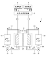
- FIG. 1 is a configuration diagram illustrating an example of a configuration of a redox flow battery system according to an embodiment.
- FIG. 1 is a configuration diagram showing an example of the configuration of the redox flow battery system according to the present embodiment, and shows an example in which a vanadium compound is used as an active material.
- the redox flow battery system 1 according to the present embodiment uses the battery cell 2 as a minimum unit and is used alone or in a form called a battery cell stack in which a plurality of battery cells are stacked, and circulates an electrolyte in the battery cell 2. Then, charge and discharge are performed.
- the redox flow battery system 1 charges power from an AC power supply 4 such as a power plant via an AC / DC converter 3 and transfers the charged power to a load power supply 5 via the AC / DC converter 3. To discharge.
- the redox flow battery system 1 includes a positive electrode cell 11 containing a positive electrode 10, a negative cell 21 containing a negative electrode 20, a cell interposed between the two electrodes 10, 20 to separate the two cells,
- the main configuration is a battery cell 2 having a diaphragm 30 that transmits light.
- the redox flow battery system 1 includes a positive electrode electrolyte tank 12 for storing the positive electrode electrolyte, a positive electrode electrolyte tank 12 for storing the positive electrode electrolyte, and a positive electrode cell 11 And a positive return pipe 14 for returning the positive electrode electrolyte from the positive electrode cell 11 to the positive electrode electrolyte tank 12.
- a pump 15 for circulating the positive electrode electrolyte and a particle size adjusting means 16 to be described later are arranged in the positive electrode outward pipe 13.
- the redox flow battery system 1 includes a negative electrode electrolyte tank 22 for storing the negative electrode electrolyte and a negative electrode electrolyte from the negative electrode electrolyte tank 22 as a circulation path of the negative electrode electrolyte that is circulated and supplied to the negative electrode cell 21.
- a negative electrode outgoing pipe 23 for sending to the cell 21 and a negative electrode return pipe 24 for returning the negative electrode electrolyte from the negative electrode cell 21 to the negative electrode electrolyte tank 22 are provided.
- a pump 25 for circulating the negative electrode electrolyte and a particle size adjusting means 26 described later are arranged in the negative electrode outgoing pipe 23.
- the electrolyte in the cathode electrolyte tank 12 passes through the cathode outgoing pipe 13 by operating the pump 15, and passes through the particle size adjusting means 16 provided in the cathode outgoing pipe 13. It is sent to battery cell 2 via The positive electrode electrolyte sent to the battery cell 2 is discharged upward from below the battery cell 2 through the inside thereof, returned to the positive electrode electrolyte tank 12 through the positive return pipe 14, and circulated in the direction of arrow A in the figure. .
- the electrolytic solution in the negative electrode electrolyte tank 22 passes through the negative electrode outgoing pipe 23, passes through the particle size adjusting means 26 disposed in the negative electrode outgoing pipe 23, and is supplied to the battery cell 2.
- the electrolytic solution sent to the battery cell 2 is discharged upward from below the battery cell 2 through the inside, returned to the negative electrode electrolyte tank 22 through the negative electrode return pipe 24, and circulated in the arrow B direction in the figure.
- an active material contained in the electrolyte solution on the positive electrode side and the negative electrode side of the redox flow battery system for example, a vanadium compound, a molybdenum compound, a tin compound, an iron compound, a chromium compound, a manganese compound, a titanium compound, a zinc compound And one or more of them.
- the vanadium compound is included in the positive electrode side and the negative electrode side electrolyte as an active material, or the manganese compound is included in the positive electrode side electrolyte as the active material, and the titanium compound is included in the negative electrode side electrolyte as an active material. Is preferred.
- the positive electrode 10 the negative electrode 20, the diaphragm 30, the positive electrode electrolyte, the negative electrode electrolyte, and the particle size adjusting means 16 and 26 will be described in detail.
- Electrode / negative electrode As the positive electrode 10 and the negative electrode 20, known electrodes can be used and are not particularly limited, but only provide a place where an active material in the electrolytic solution causes an oxidation-reduction reaction when passing through the inside of the battery cell 2. It is preferable to have a structure and a form that do not react by itself and have excellent permeability of the electrolyte solution, and have a surface area as large as possible and a low electric resistance. Further, from the viewpoint of activation of the oxidation-reduction reaction, it is preferable to have an excellent affinity for an electrolytic solution (aqueous solution). Preferably one or both are large. For example, a carbon material such as carbon felt or a graphitized carbon material, or a mesh-like titanium or zirconium substrate provided with a noble metal plating or carbon coating can be used.
- a carbon material such as carbon felt or a graphitized carbon material, or a mesh-like titanium or zirconium substrate provided with a noble metal plating or carbon coating can be used.
- diaphragm As the diaphragm 30, a known diaphragm can be used, and is not particularly limited.
- an ion exchange membrane made of an organic polymer is preferable, and both a cation exchange membrane and an anion exchange membrane can be used.
- the cation exchange membrane examples include a cation exchange membrane obtained by sulfonating a styrene-divinylbenzene copolymer, a cation exchange membrane obtained by introducing a sulfonic acid group into a copolymer of tetrafluoroethylene and perfluorosulfonylethoxyvinyl ether, Examples include a cation exchange membrane made of a copolymer of tetrafluoroethylene and perfluorovinyl ether having a carboxyl group in a side chain, and a cation exchange membrane in which a sulfonic acid group is introduced into an aromatic polysulfone copolymer.
- anion exchange membrane examples include an anion exchange membrane obtained by introducing a chloromethyl group into a styrene-divinylbenzene copolymer and aminated, an anion exchange membrane obtained by converting a vinylpyridine-divinylbenzene copolymer into a quaternary pyrididium, and an aromatic polysulfone copolymer.
- An anion exchange membrane obtained by introducing a chloromethyl group into a polymer and aminating the polymer may be used.
- the positive electrode electrolyte contains at least a dissolved active material.
- the active material when the concentration of the active material is high, the active material may be dispersed in the form of particles.
- the concentration of the active material in the positive electrode electrolyte is set based on a desired energy density and a battery capacity. More specifically, in the positive electrode electrolyte, a sum of a suitable concentration of the active material dissolved in the positive electrode electrolyte and a suitable concentration of the active material dispersed in the positive electrode electrolyte (hereinafter, simply referred to as “active material concentration”) ) May be different depending on the type of the active material, and thus is not particularly limited.
- the concentration can be 0.8 mol / L or more, preferably 1.7 mol / L or more, more preferably 2.5 mol / L or more.
- the upper limit may be 4.0 mol / L or less.
- the content can be 0.5 mol / L or more and 5.0 mol / L or less.
- the active material concentration is determined from the results obtained by ICP emission spectroscopy. Specifically, the concentration of the electrolyte becomes uniform, and the electrolyte is thoroughly stirred so that the particles are also contained, and the sample is sampled.Sulfuric acid or water is added to the sampled electrolyte, and the sample is added to the electrolyte. The contained particles are completely dissolved and appropriately diluted, and the concentration of the active material in the diluted solution is measured by ICP emission spectroscopy. From the dilution ratio, calculate the active material concentration of the electrolytic solution. This method of measuring the active material concentration is also applied to a negative electrode electrolyte described later.
- the sulfuric acid concentration of the positive electrode electrolyte also varies depending on the type of the active material, and thus is not particularly limited. It is easy to form in the liquid. Therefore, it is desirable to adjust the sulfuric acid concentration to an appropriate range according to the type of the active material used.
- the sulfuric acid concentration is preferably 0.5 mol / L or more and 6.0 mol / L or less, more preferably 1.0 mol / L or more and 3.0 mol / L or less.
- the sulfuric acid concentration of the positive electrode electrolyte is less than 0.5 mol / L, vanadium pentoxide (V 2 O 5 ), which is a pentavalent vanadium compound, is easily generated in the positive electrode electrolyte on the positive electrode cell 11 side.
- V 2 O 5 vanadium pentoxide
- the sulfuric acid concentration exceeds 6.0 mol / L, the fluidity of the electrolytic solution tends to deteriorate due to the increase in the viscosity of the electrolytic solution.
- the sulfuric acid concentration is preferably 0.5 mol / L or more and 6.0 mol / L or less.
- the positive electrode electrolyte may contain conventionally known additives such as oxo acid such as nitric acid, a protective colloid agent, and a complexing agent in order to prevent generation of precipitates.
- the negative electrode electrolyte also contains at least the dissolved active material.
- the active material when the concentration of the active material is high, the active material may be dispersed in the form of particles.
- the active material concentration in the negative electrode electrolyte is set based on a desired energy density and a battery capacity. More specifically, in the negative electrode electrolyte, the sum of a suitable concentration of the active material dissolved in the negative electrode electrolyte and a suitable concentration of the active material dispersed in the negative electrode electrolyte (hereinafter, simply referred to as “active material concentration”) ) May be different depending on the type of the active material, and thus is not particularly limited.
- the concentration when a vanadium compound is used as the active material on the negative electrode side, the concentration can be 0.8 mol / L or more, preferably 1.7 mol / L or more, more preferably 2.5 mol / L or more.
- the upper limit can be 4.0 mol / L or less.
- the concentration when a titanium compound is used as the negative electrode-side active material, the concentration can be 0.5 mol / L or more and 5.0 mol / L or less.
- the active material concentration in the negative electrode electrolyte is too high, when charging and discharging are performed, excessive generation of precipitates in the negative electrode electrolyte, or particles contained in the negative electrode electrolyte, Since the size of the precipitate particles generated in the negative electrode electrolyte becomes excessively large, the load on the particle size adjusting means described later tends to increase.
- the active material concentrations (mol / L) of the positive electrode electrolyte and the negative electrode electrolyte described above are concentrations (mol / L) of metal atoms constituting the active material contained in the electrolyte.
- the sulfuric acid concentration of the negative electrode electrolyte also varies depending on the type of the active material, and thus is not particularly limited. It is easily formed in the electrolyte. Therefore, it is desirable to adjust the sulfuric acid concentration to an appropriate range according to the type of the active material used.
- the sulfuric acid concentration is preferably 0.5 mol / L or more and 6.0 mol / L or less, more preferably 1.0 mol / L or more and 3.0 mol / L or less.
- the sulfuric acid concentration of the negative electrode electrolyte exceeds 6.0 mol / L, the fluidity of the electrolyte tends to deteriorate due to an increase in the viscosity of the electrolyte.
- the sulfuric acid concentration is preferably 0.5 mol / L or more and 6.0 mol / L or less.
- the negative electrode electrolyte may contain conventionally known additives such as an oxo acid such as nitric acid, a protective colloid agent, and a complexing agent in order to prevent the precipitation of a precipitate.
- the electrolytic solution used in the present embodiment may include an active material dispersed in a particulate form without being dissolved, and the electrolytic solution contains not only the active material but also Si or the like.
- the presence of such impurity components in the electrolytic solution causes particles contained in the electrolytic solution and particles containing precipitates generated in the electrolytic solution to be present.
- the particle size may be too large. Therefore, in the redox flow battery system 1 according to the present embodiment, the particle size adjusting means 16 and 26 for adjusting the particle size of at least the particles formed in the electrolytic solution to be small are arranged in the circulation path in which the electrolytic solution circulates. .
- the particle size adjusting means 16 and 26 are preferably arranged on one or both of a forward pipe and a return pipe constituting a circulation path, and furthermore, a positive-electrode forward pipe 13 and a negative-electrode forward pipe 23 (hereinafter simply referred to as “pipe”). "May be referred to as” outgoing pipes 13, 23 ").
- the “particles formed at least in the electrolytic solution” include not only particles generated in the electrolytic solution but also particles originally contained in the electrolytic solution.
- the cumulative 90% particle size (D90) of the volume-based particle size distribution of particles formed at least in the electrolytic solution it is preferable to adjust the cumulative 90% particle size (D90) of the volume-based particle size distribution of particles formed at least in the electrolytic solution to 5 ⁇ m or less. , More preferably 0.1 ⁇ m or more and 5 ⁇ m or less, even more preferably 0.5 ⁇ m or more and 3 ⁇ m or less.
- D90 of the particles is larger than 5 ⁇ m, the particles do not easily react as an active material, and the particles easily precipitate in the battery cells.
- the D90 of the particles is adjusted to be smaller than 0.1 ⁇ m, a high-performance particle size adjusting means may be required, and the particles may be excessively pulverized.
- the cumulative distribution diameter (D90) refers to the particle diameter at which the integrated distribution converges to 90% in the particle size distribution measurement of the particles contained in the electrolytic solution by the laser diffraction / scattering method.
- the particle size adjusting means 16 and 26 By arranging the particle size adjusting means 16 and 26 in the outgoing pipes 13 and 23 in this way, among particles formed at least in the electrolytic solution, particularly for particles having a large particle size due to crystal growth or the like, the particle size is adjusted to be small, and preferably, the cumulative 90% particle size (D90) of the volume-based particle size distribution is adjusted to 5 ⁇ m or less. As a result, the positive electrode 10 and the negative electrode 20 can continue to contribute to the above-described electrode reaction (charge / discharge reaction), and a high energy density and a high battery capacity based on the concentration can be stably obtained. .
- the particle size adjusting means 16 and 26 are not particularly limited as long as the particle size of the particles contained in the electrolytic solution can be adjusted to a small value.
- a homogenizer such as a stirring homogenizer, an ultrasonic homogenizer, a high-pressure homogenizer, and a bead mill. And the like.
- FIG. 1 shows an example in which the particle size adjusting means 16 and 26 are arranged in both the positive electrode outgoing pipe 13 and the negative electrode outgoing pipe 23, the particle size adjusting means 16 and 26 are arranged in the positive electrode outgoing pipe 13. And the negative electrode outgoing pipe 23 may be disposed only in either one of them.
- the positive return pipe 14 and the negative return pipe 24 (hereinafter simply referred to as “return pipes 14, 24”) constituting the circulation path of the electrolyte may be used. ) May be arranged in one or both of them, and may be arranged in all the pipes 13, 23, 14, 24 constituting the circulation path.
- the particle size adjusting means 16 and 26 are preferably arranged in the outgoing pipes 13 and 23 from the viewpoint of suppressing the supply of the particles having the increased particle size into the battery cell 2. Further, from the viewpoint of more preferably adjusting the particle diameter of the particles, it is preferable that the particle diameter adjusting means 16 and 26 are disposed in both the outgoing pipes 13 and 23 and the return pipes 14 and 24. Further, the particle size adjusting means 16 and 26 may be arranged in one or both of the positive electrode electrolyte tank 12 and the negative electrode electrolyte tank 22.
- the operating method of the redox flow battery system according to the present embodiment is the above-described operating method of the redox flow battery system that performs charge and discharge by circulating the electrolyte. Then, the method includes a particle size adjusting step of reducing the particle size of particles formed at least in the electrolytic solution.
- the particle size adjusting step it is preferable to adjust the cumulative distribution diameter (D90) of the volume-based particle size distribution of at least the particles formed in the electrolytic solution to 5 ⁇ m or less.
- the positive electrode 10 and the negative electrode 20 can continue to contribute to the above-described electrode reaction (charge / discharge reaction), and a high energy density and a high battery capacity based on the concentration can be stably obtained. .
- the electrolyte pipe for a redox flow battery according to the present embodiment is the electrolyte pipe used for the redox flow battery 1 that circulates and charges and discharges the electrolyte described above. And it has the particle size adjustment means 16 and 26 which adjust the particle size of the particle
- the particle size adjusting means 16, 26 is preferably a homogenizer or a disperser / pulverizer.
- the particle size adjusting means 16 and 26 adjust the cumulative distribution diameter (D90) of the volume-based particle size distribution of the particles formed at least in the electrolytic solution to 5 ⁇ m or less.
- the intensity of stirring can be adjusted by selecting an appropriate type of stirring rod and a suitable number of rotations.
- the electrolyte pipe includes a positive electrode outward pipe 13 for supplying an electrolyte from the positive electrode electrolyte tank 12 for storing the electrolyte on the positive electrode side to the positive electrode cell 11 and a negative electrode electrolyte tank 22 for storing the electrolyte on the negative electrode side. From the positive electrode side to return to the positive electrode electrolyte tank 12 on the positive electrode side, and from the negative electrode cell 21 to the negative electrode from the negative electrode cell 21 on the negative electrode side. It is preferable that at least one of the negative return pipes 24 returned to the electrolytic solution tank 22 is used.
- the cumulative 90% particle size (D90) of the volume-based particle size distribution is adjusted to 5 ⁇ m or less.
- Example 1 As the battery cell 2, the positive electrode 10 and the negative electrode 20 have carbon felt (area 25 cm 2 ), the diaphragm 30 has an ion-exchange membrane, and the positive electrode electrolyte has a tetravalent vanadium concentration of 3.0 mol / L, which is 1.7 mol / L.
- a single cell for experiment was prepared using 250 mL of an aqueous solution of —H 2 SO 4 and 250 mL of a 3.0 mol / L aqueous solution of H 2 SO 4 having a trivalent vanadium concentration of 1.7 mol / L as a negative electrode electrolyte.
- the homogenizers serving as the particle size adjusting means 16 and 26 are arranged in the outgoing pipes 13 and 23, and the positive electrode cell 11 and the negative electrode cell 21 are respectively provided with the positive electrode electrolyte.
- the battery was charged at a current density of 1000 A / m 2 while circulating and supplying the negative electrode electrolyte at a rate of 200 mL / min. When the voltage reached 1.6 V, the charging was stopped. Subsequently, discharging was performed at 1000 A / m 2 , and when the voltage reached 1.0 V, the discharging was terminated. This charge and discharge were repeated for 1000 cycles.
- the particles of the vanadium compound contained in the electrolytic solution are adjusted to have a volume-based particle size distribution of 90% particle size (D90) of 5 ⁇ m or less by the homogenizers as the particle size control means 16 and 26.
- D90 of the particles contained in the electrolytic solution was measured using a laser diffraction / scattering type particle size distribution analyzer (LA-920, manufactured by Horiba, Ltd.). Then, based on the measured value of D90, the number of rotations of the stirring rod of the particle size adjusting means 16 and 26 (homogenizer) was adjusted so that the D90 of the particles became 5 ⁇ m.
- the rotational speed of the stirring rod is increased, and when the measured value of D90 is smaller than 5 ⁇ m, the rotational speed of the stirring bar is decreased so that the D90 of the particles is 5 ⁇ m. did.
- Example 2 Charge and discharge were repeated in the same manner as in Example 1 except that the vanadium concentrations of the positive electrode electrolyte and the negative electrode electrolyte were set to 2.8 mol / L.
- Example 3 Charge and discharge were repeated in the same manner as in Example 1 except that the vanadium concentrations of the positive electrode electrolyte and the negative electrode electrolyte were 4.0 mol / L.
- Example 4 Charge and discharge were repeated in the same manner as in Example 1 except that the vanadium concentrations of the positive electrode electrolyte and the negative electrode electrolyte were set to 0.8 mol / L.
- Example 5 250 mL of a 3.0 mol / L-H 2 SO 4 aqueous solution having a trivalent manganese concentration of 1.5 mol / L is used as a positive electrode electrolyte, and a trivalent titanium concentration of 1.5 mol / L is used as a negative electrode electrolyte.
- the charge / discharge was repeated in the same manner as in Example 1, except that 250 mL of a 2.0 mol / L-H 2 SO 4 aqueous solution was used.
- Example 6 The charge / discharge cycle was repeated 1,000 times in the same manner as in Example 2, except that the particle size adjusting means 16 and 26 (homogenizer) were arranged in the outward pipes 13 and 23 and the return pipes 14 and 24, respectively.
- Example 7 Same as Example 1 except that the homogenizer as the particle size adjusting means 16 and 26 adjusted the type and rotation speed of the stirring rod of the homogenizer so that the D90 of the vanadium compound particles contained in the electrolytic solution was 8 ⁇ m. Then, charging and discharging were repeated 1000 cycles.
- Example 8 Same as Example 1 except that the type and rotation speed of the stirring rod of the homogenizer were adjusted by the homogenizers as the particle size adjusting means 16 and 26 so that the D90 of the vanadium compound particles contained in the electrolytic solution was 3 ⁇ m. Then, charging and discharging were repeated 1000 cycles.
- Example 1 in which the vanadium concentration of the electrolytic solution was 1.7 mol / L and the particle size adjusting means 16 and 26 were disposed in the outward pipes 13 and 23, both the energy density and the battery capacity in the first cycle charge and discharge were reduced. When the charge and discharge at the 1000th cycle were 100% (reference), both the energy density and the reduction rate of the battery capacity were about 5%. On the other hand, in Comparative Example 1 in which the particle size adjusting means is not provided, when both the energy density and the battery capacity in the first cycle of charging and discharging are 100% (reference), the energy in the charging and discharging of the 1000th cycle is The reduction rates of the density and the battery capacity were both about 12%, which was larger than that of Example 1.
- Example 2 in which the vanadium concentration of the electrolytic solution was 2.8 mol / L and the particle size adjusting means 16 and 26 were disposed in the outward pipes 13 and 23, both the energy density and the battery capacity in the first cycle of charging and discharging were reduced.
- the charge / discharge rate was set to 100% (reference)
- both the energy density and the reduction rate of the battery capacity were about 15% in the charge and discharge at the 1000th cycle.
- Comparative Example 2 in which the particle size adjusting means is not provided when both the energy density and the battery capacity in the first cycle charge and discharge are set to 100% (reference), the energy in the charge and discharge in the 1000th cycle is Both the density and the reduction rate of the battery capacity were about 31%, which was larger than that of Example 2.
- Example 3 in which the vanadium concentration of the electrolytic solution was 4.0 mol / L and the particle size adjusting means 16 and 26 were disposed in the outward pipings 13 and 23, both the energy density and the battery capacity in the first cycle of charging and discharging were reduced.
- both the energy density and the reduction rate of the battery capacity were about 29%.
- Comparative Example 3 in which the particle size adjusting means is not provided, when both the energy density and the battery capacity in the first cycle charge and discharge are set to 100% (reference), the energy in the 1000th cycle charge and discharge is The reduction rates of the density and the battery capacity were both about 54%, which was larger than that of Example 3.
- Example 4 in which the vanadium concentration of the electrolytic solution was 0.8 mol / L and the particle size adjusting means 16 and 26 were disposed in the outward pipings 13 and 23, both the energy density and the battery capacity in the first cycle of charging and discharging were reduced.
- the charge / discharge rate was set to 100% (standard)
- both the energy density and the reduction rate of the battery capacity were about 2% in the charge and discharge at the 1000th cycle.
- the particle size adjusting means when both the energy density and the battery capacity in the first cycle charge and discharge are set to 100% (reference), the energy in the 1000th cycle charge and discharge is The reduction rates of the density and the battery capacity were both about 8%, which was larger than that of Example 4.
- Example 5 in which the manganese concentration in the positive electrode electrolyte was 1.5 mol / L, the titanium concentration in the negative electrode electrolyte was 1.5 mol / L, and the particle size adjusting means 16 and 26 were disposed in the outward pipes 13 and 23.
- the rate of decrease in both the energy density and the battery capacity in the charge and discharge in the 1000th cycle was about 10%.
- Example 6 in which the concentration of vanadium in the electrolytic solution was 2.8 mol / L, and the particle size adjusting means 16 and 26 were disposed in the outgoing pipes 13 and 23 and the return pipes 14 and 24, the charge and discharge in the first cycle were performed.
- the rate of decrease in both the energy density and the battery capacity was about 11% in the charge and discharge at the 1000th cycle. It was confirmed that the energy density and the battery capacity by repeating charge / discharge can be further reduced as compared with Example 2 in which the particle diameter adjusting means 16 and 26 were arranged only on the outward pipes 13 and 23.
- the surfaces of the electrodes 10, 20 and the surface of the diaphragm 30 of the battery cells 2 of Examples 1 to 8 in which the particle size adjusting means 16, 26 were arranged showed almost no change even after repeating charge and discharge for 1,000 cycles.
- the precipitates of the vanadium compound, the manganese compound, and the titanium compound are fixed on the surfaces of the electrodes 10 and 20 and the diaphragm 30 of the battery cells 2 of Comparative Examples 1 to 5 in which the particle size adjusting means is not provided. It was confirmed that.
- Example 7 in which the D90 of the vanadium compound particles contained in the electrolytic solution was adjusted to 8 ⁇ m, the decrease in energy density after 1000 cycles from the first cycle was about 7%, and the decrease in battery capacity was about 7%. %.
- Example 8 in which the D90 of the vanadium compound particles contained in the electrolytic solution was adjusted to 3 ⁇ m, the decrease in energy density after 1000 cycles from the first cycle was about 4%, and the decrease in battery capacity was about 4%. %. From the results of Examples 1, 7, and 8, the D90 of the vanadium compound particles adjusted by using the particle size adjusting means 16 and 26 (homogenizer) is reduced to reduce the energy density due to repeated charge and discharge. It was confirmed that the battery capacity and the battery capacity were less likely to decrease.
Landscapes
- Life Sciences & Earth Sciences (AREA)
- Engineering & Computer Science (AREA)
- Manufacturing & Machinery (AREA)
- Sustainable Development (AREA)
- Sustainable Energy (AREA)
- Chemical & Material Sciences (AREA)
- Chemical Kinetics & Catalysis (AREA)
- Electrochemistry (AREA)
- General Chemical & Material Sciences (AREA)
- Fuel Cell (AREA)
- Battery Electrode And Active Subsutance (AREA)
Abstract
充放電を繰り返し行ったとしても、所望のエネルギー密度や電池容量を安定して得ることができる、レドックスフロー電池システム等を提供する。 レドックスフロー電池システム1は、電解液を循環させて充放電を行なうものであって、電解液が循環する循環経路に、電解液中に少なくとも生成してなる粒子の粒径を小さく調整する粒径調整手段16、26を有する。また、レドックスフロー電池システム1の運転方法は、電解液を循環させて充放電を行なうものであって、電解液中に少なくとも生成してなる粒子の粒径を小さくする粒径調整工程を有する。また、レドックスフロー電池用電解液配管は、電解液を循環させて充放電を行なうレドックスフロー電池1用の電解液配管であって、電解液中に少なくとも生成してなる粒子の粒径を小さく調整する粒径調整手段16、26を有する。
Description
本発明は、電解液を循環させて充放電を行なうレドックスフロー電池システム及びその運転方法並びにレドックスフロー電池用電解液配管に関する。
電力貯蔵用の電池として、種々の電池の開発が進められているが、電解液流通型の電池、いわゆるレドックスフロー電池がある。レドックスフロー電池は、正極と負極と両電極の間に介在される隔膜とを有する電池セルに、正極電解液及び負極電解液をそれぞれ供給循環し、電力変換器(例えば、交流/直流変換器等)を介して充放電を行なう。電解液には、通常酸化還元により価数が変化する金属イオン(活物質)を含有する水溶液が使用されている。例えば、正極及び負極の活物質にバナジウム(V)を用いたバナジウム系レドックスフロー電池がよく知られている。
一般に、レドックスフロー電池では、電解液中の活物質の量が多いほど、エネルギー密度が増し、電池容量が高まる。例えば、特許文献1には、電解液中に、活物質であるバナジウム化合物を、溶質(溶解性イオン)、及び直径が100μm以下であり、電解液中で溶解しない分散質(懸濁性物質)として含み、活物質のバナジウム濃度の合計が2.5M(mol/L)以上である、高濃度のバナジウム電解液が開示されている。
しかしながら、電解液を繰り返し循環させて充放電を行った場合、電解液中の活物質が析出物として徐々に電池セル内や電解液中に析出し、結晶成長によって粒子状又は塊状の析出物を形成することがある。また、充放電を行なう際に、電解液中にSi等の不純物成分が存在すると、電解液中の活物質の濃度が低くても、電池セル内や電解液中に析出物が生成しやすくなる傾向がある。そのため、析出物が電池セル内で詰まる等によって、電解液の流動性が維持できなくなり、レドックスフロー電池のエネルギー密度や電池容量が低下する問題があった。また、析出物の結晶成長が進むと、電極反応の困難な活物質の割合が比較的短期間で増加することで、レドックスフロー電池のエネルギー密度や電池容量がさらに大きく低下する問題があった。
特許文献1においては、活物質であるバナジウム化合物として、直径が100μm以下の分散質(懸濁性物質)を含むことにより、高濃度のバナジウム電解液が実現されているものの、析出物の結晶成長によるエネルギー密度の低下や電池容量の低下を抑制する点では、さらなる改良が求められている。
本発明は、充放電を繰り返し行ったとしても、所望のエネルギー密度や電池容量を安定して得ることができる、レドックスフロー電池システム及びその運転方法並びにレドックスフロー電池用電解液配管を提供することを目的とする。
本発明者らは、電解液が循環する循環経路中に、電解液中に少なくとも生成してなる粒子の粒径を小さく調整する粒径調整手段を配置することにより、レドックスフロー電池のエネルギー密度や電池容量が、充放電を繰り返し行うことによって低下するのを抑制することができることを見出し、本発明を完成するに至った。より具体的には、本発明は、以下のものを提供する。
(1)本発明は、電解液を循環させて充放電を行なうレドックスフロー電池システムであって、前記電解液が循環する循環経路に、前記電解液中に少なくとも生成してなる粒子の粒径を小さくする粒径調整手段を有することを特徴とする、レドックスフロー電池システムである。
(2)また、本発明は、前記粒径調整手段は、前記粒子の体積基準の粒度分布の累積90%粒径(D90)を5μm以下に調整する、(1)に記載のレドックスフロー電池システムである。
(3)また、本発明は、前記循環経路は、前記電解液を貯蔵する電解液タンクと、前記電解液をタンクから電池セルに送る往路配管と、前記電解液を前記電池セルから前記電解液タンクに戻す復路配管とを有し、前記粒径調整手段は、前記往路配管及び前記復路配管の一方又は両方に配置される、(1)又は(2)に記載のレドックスフロー電池システムである。
(4)また、本発明は、前記粒径調整手段は、ホモジナイザー又は分散・粉砕器である、(1)から(3)までのいずれか1項に記載のレドックスフロー電池システムである。
(5)本発明は、電解液を循環させて充放電を行なうレドックスフロー電池システムの運転方法であって、前記電解液中に少なくとも生成してなる粒子の粒径を小さくする粒径調整工程を有することを特徴とする、レドックスフロー電池システムの運転方法である。
(6)また、本発明は、前記粒径調整工程では、前記粒子の体積基準の粒度分布の累積90%粒径(D90)を5μm以下に調整する、(5)に記載のレドックスフロー電池システムの運転方法である。
(7)本発明は、電解液を循環させて充放電を行なうレドックスフロー電池用の電解液配管であって、前記電解液中に少なくとも生成してなる粒子の粒径を小さく調整する粒径調整手段を有することを特徴とする、レドックスフロー電池用電解液配管である。
(8)また、本発明は、前記粒径調整手段は、ホモジナイザー又は分散・粉砕器である、(7)に記載のレドックスフロー電池用電解液配管である。
(9)また、本発明は、前記粒径調整手段は、前記粒子の体積基準の粒度分布の累積90%粒径(D90)を5μm以下に調整する、(7)又は(8)に記載のレドックスフロー電池用電解液配管である。
(10)また、本発明は、前記電解液配管は、前記電解液を貯蔵する電解液タンクから電池セルに電解液を供給する往路配管および前記電解液を前記電池セルから前記電解液タンクに戻す復路配管の少なくとも一つである(7)から(9)までのいずれか1項に記載のレドックスフロー電池用電解液配管である。
本発明によれば、充放電を繰り返し行ったとしても、所望のエネルギー密度や電池容量を安定して得ることができる、レドックスフロー電池システム及びその運転方法並びにレドックスフロー電池用電解液配管を提供することができる。
以下、本発明の具体的な実施形態について、図面を参照しながら詳細に説明する。なお、本発明は、以下の実施形態に限定されるものではなく、本発明の要旨を変更しない範囲で種々の変更が可能である。
<レドックスフロー電池システム>
図1は、本実施形態に係るレドックスフロー電池システムの構成の一例を示す構成図であり、バナジウム化合物を活物質として用いた場合を例として示すものである。本実施形態に係るレドックスフロー電池システム1は、電池セル2を最小単位として、これを単独で、又は複数枚積層した電池セルスタックと称される形態で使用され、電池セル2に電解液を循環させて充放電を行なう。例えば、このレドックスフロー電池システム1は、交流/直流変換器3を介して発電所等の交流電源4からの電力を充電し、充電した電力を、交流/直流変換器3を介して負荷電源5に放電する。
図1は、本実施形態に係るレドックスフロー電池システムの構成の一例を示す構成図であり、バナジウム化合物を活物質として用いた場合を例として示すものである。本実施形態に係るレドックスフロー電池システム1は、電池セル2を最小単位として、これを単独で、又は複数枚積層した電池セルスタックと称される形態で使用され、電池セル2に電解液を循環させて充放電を行なう。例えば、このレドックスフロー電池システム1は、交流/直流変換器3を介して発電所等の交流電源4からの電力を充電し、充電した電力を、交流/直流変換器3を介して負荷電源5に放電する。
レドックスフロー電池システム1は、正極電極10を内蔵する正極セル11と、負極電極20を内蔵する負極セル21と、両電極10、20の間に介在されて両セルを分離するとともに、所定のイオンを透過する隔膜30とを有する電池セル2を主構成とする。
そして、レドックスフロー電池システム1は、正極セル11に循環供給する正極電解液の循環経路として、正極電解液を貯蔵する正極電解液タンク12と、正極電解液を正極電解液タンク12から正極セル11に送る正極往路配管13と、正極電解液を正極セル11から正極電解液タンク12に戻す正極復路配管14とを備える。正極往路配管13には、正極電解液を循環させるためのポンプ15と、後述する粒径調整手段16が配置される。
同様に、このレドックスフロー電池システム1は、負極セル21に循環供給する負極電解液の循環経路として、負極電解液を貯蔵する負極電解液タンク22と、負極電解液を負極電解液タンク22から負極セル21に送る負極往路配管23と、負極電解液を負極セル21から負極電解液タンク22に戻す負極復路配管24とを備える。負極往路配管23には、負極電解液を循環させるためのポンプ25と、後述する粒径調整手段26が配置される。
上記構成のレドックスフロー電池システム1において、正極電解液タンク12内の電解液は、ポンプ15を作動させることにより、正極往路配管13を通り、正極往路配管13に配設した粒径調整手段16を経由して電池セル2に送られる。電池セル2に送られた正極電解液は、電池セル2の下方から内部を通って上方に排出され、正極復路配管14を通して正極電解液タンク12に戻されて、図中矢印A方向に循環する。同様に、負極電解液タンク22内の電解液は、ポンプ25を作動させることにより、負極往路配管23を通り、負極往路配管23に配設した粒径調整手段26を経由して電池セル2に送られる。電池セル2に送られた電解液は、電池セル2の下方から内部を通って上方に排出され、負極復路配管24を通して負極電解液タンク22に戻されて、図中矢印B方向に循環する。
これにより、電池セル2内で電解液に含まれる活物質の酸化還元反応が行われ、電力の取出し又は貯蔵が可能となる。
ここで、レドックスフロー電池システム1の正極側及び負極側の電解液に含まれる活物質としては、例えば、バナジウム化合物、モリブデン化合物、スズ化合物、鉄化合物、クロム化合物、マンガン化合物、チタン化合物、亜鉛化合物のうち1種又は2種以上が挙げられる。特に、バナジウム化合物を活物質として正極側及び負極側の電解液に含むこと、または、マンガン化合物を活物質として正極側の電解液に含み、且つチタン化合物を活物質として負極側の電解液に含むことが好ましい。
以下、正極電極10、負極電極20、隔膜30、正極電解液、負極電解液、粒径調整手段16、26についてそれぞれ詳細に説明する。
(正極電極・負極電極)
正極電極10及び負極電極20としては、公知の電極を用いることができ、特に限定されないが、電解液中の活物質が電池セル2内を通過する際に酸化還元反応を生じる場を提供するのみで自ら反応せず、電解液の通過性に優れた構造、形態を有しており、かつ、極力表面積が広く、電気抵抗が低いことが好ましい。さらに、酸化還元反応の活性化の観点からは、電解液(水溶液)との親和性に優れていることが好ましく、さらに副反応となる水の分解を生じさせない観点から、水素過電圧及び酸素過電圧の一方又は両方が大きいことが好ましい。例えば、カーボンフェルトのようなカーボン材又はそれを黒鉛化したものや、メッシュ状のチタニウム又はジルコニウムの基板に貴金属めっき又はカーボンコートを施したものが挙げられる。
正極電極10及び負極電極20としては、公知の電極を用いることができ、特に限定されないが、電解液中の活物質が電池セル2内を通過する際に酸化還元反応を生じる場を提供するのみで自ら反応せず、電解液の通過性に優れた構造、形態を有しており、かつ、極力表面積が広く、電気抵抗が低いことが好ましい。さらに、酸化還元反応の活性化の観点からは、電解液(水溶液)との親和性に優れていることが好ましく、さらに副反応となる水の分解を生じさせない観点から、水素過電圧及び酸素過電圧の一方又は両方が大きいことが好ましい。例えば、カーボンフェルトのようなカーボン材又はそれを黒鉛化したものや、メッシュ状のチタニウム又はジルコニウムの基板に貴金属めっき又はカーボンコートを施したものが挙げられる。
(隔膜)
隔膜30としては、公知の隔膜を用いることができ、特に限定されないが、例えば有機高分子からなるイオン交換膜が好ましく、また、カチオン交換膜及びアニオン交換膜のいずれも用いることができる。
隔膜30としては、公知の隔膜を用いることができ、特に限定されないが、例えば有機高分子からなるイオン交換膜が好ましく、また、カチオン交換膜及びアニオン交換膜のいずれも用いることができる。
カチオン交換膜としては、スチレン-ジビニルベンゼン共重合体をスルホン化して得られるカチオン交換膜、テトラフルオロエチレンとパーフルオロ・スルホニル・エトキシビニルエーテルとの共重合体にスルホン酸基を導入したカチオン交換膜、テトラフルオロエチレンとカルボキシル基を側鎖に持つパーフルオロビニルエーテルとの共重合体からなるカチオン交換膜、芳香族ポリスルホン共重合体にスルホン酸基を導入したカチオン交換膜等が挙げられる。
アニオン交換膜としては、スチレン-ジビニルベンゼン共重合体にクロロメチル基を導入してアミノ化したアニオン交換膜、ビニルピリジン-ジビニルベンゼン共重合体を4級ピリジジウム化したアニオン交換膜、芳香族ポリスルホン共重合体にクロロメチル基を導入してアミノ化したアニオン交換膜等が挙げられる。
(正極電解液)
正極電解液は、溶解した活物質を少なくとも含む。特に、活物質の濃度が高い場合等には、粒子状に分散した活物質を含んでいてもよい。正極電解液中の活物質の濃度は、所望のエネルギー密度や電池容量に基づいて設定される。より具体的には、正極電解液における、正極電解液中に溶解した活物質と、正極電解液中に粒子状に分散した活物質の好適な濃度の合計(以下、単に「活物質濃度」という場合がある)は、活物質の種類によっても異なるため、特に限定はしない。例えば、正極側の活物質としてバナジウム化合物を用いる場合には、0.8mol/L以上、好ましくは1.7mol/L以上、より好ましくは2.5mol/L以上とすることができ、他方でその上限は4.0mol/L以下としてもよい。また、正極側の活物質としてマンガン化合物を用いる場合には、0.5mol/L以上5.0mol/L以下とすることができる。正極電解液中の活物質濃度を高めることにより、高い電池容量やエネルギー密度を実現することができる。他方で、正極電解液中の活物質濃度が高すぎると、充放電を行ったときに、正極電解液中での析出物の生成が過多となり、または、正極電解液中に含まれる粒子や、正極電解液中で生成される析出物の粒子の粒径が過大となるため、後述する粒径調整手段における負荷が高まる傾向がある。
正極電解液は、溶解した活物質を少なくとも含む。特に、活物質の濃度が高い場合等には、粒子状に分散した活物質を含んでいてもよい。正極電解液中の活物質の濃度は、所望のエネルギー密度や電池容量に基づいて設定される。より具体的には、正極電解液における、正極電解液中に溶解した活物質と、正極電解液中に粒子状に分散した活物質の好適な濃度の合計(以下、単に「活物質濃度」という場合がある)は、活物質の種類によっても異なるため、特に限定はしない。例えば、正極側の活物質としてバナジウム化合物を用いる場合には、0.8mol/L以上、好ましくは1.7mol/L以上、より好ましくは2.5mol/L以上とすることができ、他方でその上限は4.0mol/L以下としてもよい。また、正極側の活物質としてマンガン化合物を用いる場合には、0.5mol/L以上5.0mol/L以下とすることができる。正極電解液中の活物質濃度を高めることにより、高い電池容量やエネルギー密度を実現することができる。他方で、正極電解液中の活物質濃度が高すぎると、充放電を行ったときに、正極電解液中での析出物の生成が過多となり、または、正極電解液中に含まれる粒子や、正極電解液中で生成される析出物の粒子の粒径が過大となるため、後述する粒径調整手段における負荷が高まる傾向がある。
なお、活物質濃度は、ICP発光分光法で得た結果から求める。具体的には、電解液の濃度が均一になり、且つ粒子も均一に含まれるように電解液をよく攪拌してサンプリングし、そのサンプリングした電解液に硫酸又は水を加えて、電解液中に含まれる粒子を完全に溶解させるとともに適宜希釈し、希釈後の溶液における活物質の濃度をICP発光分光法により測定する。希釈倍率から、電解液の活物質濃度を計算する。この活物質濃度の測定方法は、後述する負極電解液にも適用される。
正極電解液の硫酸濃度もまた、活物質の種類によって異なるため、特に限定はしないが、硫酸濃度が低すぎると、正極セル11側において、正極側の活物質に由来する析出物が、正極電解液中に生成しやすくなる。このため、使用する活物質の種類に応じて、硫酸濃度を適正範囲に調整することが望ましい。例えば、活物質としてバナジウム化合物を用いる場合、硫酸濃度は、好ましくは0.5mol/L以上6.0mol/L以下、より好ましくは1.0mol/L以上3.0mol/L以下である。正極電解液の硫酸濃度が0.5mol/L未満であると、正極セル11側において、5価のバナジウム化合物である五酸化バナジウム(V2O5)が、正極電解液中に生成しやすくなる。他方で、硫酸濃度が6.0mol/Lを超えると、電解液の粘度の上昇により、電解液の流動性が悪くなりやすくなる。また、正極側の活物質としてマンガン化合物を用いる場合、硫酸濃度は、好ましくは0.5mol/L以上6.0mol/L以下である。
なお、正極電解液には、析出物の生成を防止するために、従来公知の硝酸等のオキソ酸や保護コロイド剤、錯化剤等の添加物を含んでもよい。
(負極電解液)
負極電解液も、溶解した活物質を少なくとも含む。特に、活物質の濃度が高い場合等には、粒子状に分散した活物質を含んでいてもよい。負極電解液における活物質濃度は所望のエネルギー密度や電池容量に基づいて設定される。より具体的には、負極電解液における、負極電解液中に溶解した活物質と、負極電解液中に粒子状に分散した活物質の好適な濃度の合計(以下、単に「活物質濃度」という場合がある)は、活物質の種類によっても異なるため、特に限定はしない。例えば、負極側の活物質としてバナジウム化合物を用いる場合には、0.8mol/L以上、好ましくは1.7mol/L以上、より好ましくは2.5mol/L以上とすることができ、他方でその上限は4.0mol/L以下とすることができる。また、負極側の活物質としてチタン化合物を用いる場合には、0.5mol/L以上、5.0mol/L以下とすることができる。負極電解液中の活物質濃度を高めることにより、高い電池容量やエネルギー密度を実現することができる。他方で、負極電解液中の活物質濃度が高すぎると、充放電を行ったときに、負極電解液中での析出物の生成が過多となり、または、負極電解液中に含まれる粒子や、負極電解液中で生成される析出物の粒子の粒径が過大となるため、後述する粒径調整手段における負荷が高まる傾向がある。なお、上述した正極電解液及び負極電解液の活物質濃度(mol/L)は、電解液に含まれる活物質を構成する金属原子の濃度(mol/L)である。
負極電解液も、溶解した活物質を少なくとも含む。特に、活物質の濃度が高い場合等には、粒子状に分散した活物質を含んでいてもよい。負極電解液における活物質濃度は所望のエネルギー密度や電池容量に基づいて設定される。より具体的には、負極電解液における、負極電解液中に溶解した活物質と、負極電解液中に粒子状に分散した活物質の好適な濃度の合計(以下、単に「活物質濃度」という場合がある)は、活物質の種類によっても異なるため、特に限定はしない。例えば、負極側の活物質としてバナジウム化合物を用いる場合には、0.8mol/L以上、好ましくは1.7mol/L以上、より好ましくは2.5mol/L以上とすることができ、他方でその上限は4.0mol/L以下とすることができる。また、負極側の活物質としてチタン化合物を用いる場合には、0.5mol/L以上、5.0mol/L以下とすることができる。負極電解液中の活物質濃度を高めることにより、高い電池容量やエネルギー密度を実現することができる。他方で、負極電解液中の活物質濃度が高すぎると、充放電を行ったときに、負極電解液中での析出物の生成が過多となり、または、負極電解液中に含まれる粒子や、負極電解液中で生成される析出物の粒子の粒径が過大となるため、後述する粒径調整手段における負荷が高まる傾向がある。なお、上述した正極電解液及び負極電解液の活物質濃度(mol/L)は、電解液に含まれる活物質を構成する金属原子の濃度(mol/L)である。
負極電解液の硫酸濃度もまた、活物質の種類によっても異なるため、特に限定はしないが、硫酸濃度が高すぎると、負極セル21側において、負極側の活物質に由来する析出物が、負極電解液中に生成しやすくなる。このため、使用する活物質の種類に応じて、硫酸濃度を適正範囲に調整することが望ましい。例えば、活物質としてバナジウム化合物を用いる場合、硫酸濃度は、好ましくは0.5mol/L以上6.0mol/L以下、より好ましくは1.0mol/L以上3.0mol/L以下である。負極電解液の硫酸濃度が6.0mol/Lを超えると、電解液の粘度の上昇により、電解液の流動性が悪くなりやすくなる。また、負極側の活物質としてチタン化合物を用いる場合、硫酸濃度は、好ましくは0.5mol/L以上6.0mol/L以下である。
なお、負極電解液には、析出物の析出を防止するために、従来公知の硝酸等のオキソ酸や保護コロイド剤、錯化剤等の添加物を含んでもよい。
(粒径調整手段)
上述したように、本実施形態で使用される電解液では、溶解せずに粒子状に分散した活物質が含まれることがあり、また、電解液中には、活物質だけではなく、Si等の不純物成分が含まれている場合が多く、このような不純物成分が電解液中に存在することによって、電解液中に含まれる粒子や、電解液中で生成される析出物を含んだ粒子の粒径が過大となることがある。そこで、本実施形態に係るレドックスフロー電池システム1は、電解液が循環する循環経路に、電解液中に少なくとも生成してなる粒子の粒径を小さく調整する粒径調整手段16、26を配置する。ここで、粒径調整手段16、26は、循環経路を構成する往路配管及び復路配管の一方又はその両方に配置されることが好ましく、さらに、正極往路配管13及び負極往路配管23(以下、単に「往路配管13、23」という場合がある。)の一方または両方に配置することが好ましい。なお、「電解液中に少なくとも生成してなる粒子」には、電解液中で生成される粒子のほか、電解液中に最初から含まれている粒子も含まれる。
上述したように、本実施形態で使用される電解液では、溶解せずに粒子状に分散した活物質が含まれることがあり、また、電解液中には、活物質だけではなく、Si等の不純物成分が含まれている場合が多く、このような不純物成分が電解液中に存在することによって、電解液中に含まれる粒子や、電解液中で生成される析出物を含んだ粒子の粒径が過大となることがある。そこで、本実施形態に係るレドックスフロー電池システム1は、電解液が循環する循環経路に、電解液中に少なくとも生成してなる粒子の粒径を小さく調整する粒径調整手段16、26を配置する。ここで、粒径調整手段16、26は、循環経路を構成する往路配管及び復路配管の一方又はその両方に配置されることが好ましく、さらに、正極往路配管13及び負極往路配管23(以下、単に「往路配管13、23」という場合がある。)の一方または両方に配置することが好ましい。なお、「電解液中に少なくとも生成してなる粒子」には、電解液中で生成される粒子のほか、電解液中に最初から含まれている粒子も含まれる。
具体的には、この粒径調整手段16、26では、電解液中に少なくとも生成してなる粒子の体積基準の粒度分布の累積90%粒径(D90)を、5μm以下に調整することが好ましく、0.1μm以上5μm以下に調整することがより好ましく、0.5μm以上3μm以下に調整することがさらに好ましい。粒子のD90が5μmより大きいと、活物質として反応しにくくなり、且つ粒子が電池セル内に析出しやすくなる。また、粒子のD90を0.1μmより小さく調整する場合、高性能な粒径調整手段が必要になることがあり、過度に粒子を粉砕することになる恐れがある。ここで、累積分布径(D90)とは、電解液中に含まれる粒子についての、レーザー回折/散乱法による粒度分布測定における、積算分布が90%に収束する粒子径のことをいう。
このように、往路配管13、23に粒径調整手段16、26を配置することにより、電解液中に少なくとも生成してなる粒子のうち、特に結晶成長等によって粒径が大きくなった粒子について、電池セル2に供給される前に粒径が小さく調整され、好ましくは体積基準の粒度分布の累積90%粒径(D90)が5μm以下に調整される。その結果、正極電極10や負極電極20が、上述するような電極反応(充放電反応)に寄与し続けることが可能となり、その濃度に基づく高いエネルギー密度や電池容量を安定して得ることができる。
粒径調整手段16、26としては、電解液中に含まれる粒子の粒径を小さく調整することができれば、特に限定されないが、例えば撹拌式ホモジナイザー、超音波ホモジナイザー、高圧ホモジナイザー等のホモジナイザーや、ビーズミル等の分散・粉砕器が挙げられる。
なお、図1に示す例では、粒径調整手段16、26を正極往路配管13および負極往路配管23の両方に配置する例について示したが、粒径調整手段16、26は、正極往路配管13および負極往路配管23のいずれか一方のみに配置してもよく、電解液の循環経路を構成する正極復路配管14および負極復路配管24(以下、単に「復路配管14、24」という場合がある。)の一方または両方に配置してもよく、循環経路を構成する全ての配管13、23、14、24に配置してもよい。粒径調整手段16、26は、粒径の大きくなった粒子が電池セル2内に供給されるのを抑制する点からは、往路配管13、23に配置されるのが好ましい。また、粒径調整手段16、26は、粒子の粒径をより好ましく調整する点からは、往路配管13、23と復路配管14、24の両方に配置することが好ましい。また、粒径調整手段16、26は、正極電解液タンク12内および負極電解液タンク22内の一方または両方に配置されてもよい。
<レドックスフロー電池システムの運転方法>
本実施形態に係るレドックスフロー電池システムの運転方法は、上述した、電解液を循環させて充放電を行なうレドックスフロー電池システムの運転方法である。そして、電解液中に少なくとも生成してなる粒子の粒径を小さくする粒径調整工程を含む。
本実施形態に係るレドックスフロー電池システムの運転方法は、上述した、電解液を循環させて充放電を行なうレドックスフロー電池システムの運転方法である。そして、電解液中に少なくとも生成してなる粒子の粒径を小さくする粒径調整工程を含む。
具体的には、粒径調整工程では、電解液中に少なくとも生成してなる粒子の体積基準の粒度分布の累積分布径(D90)を5μm以下に調整することが好ましい。
このような粒径調整工程を含むことにより、電解液中に少なくとも生成してなる粒子のうち、特に結晶成長等によって粒径が大きくなった粒子について、電池セル2に供給される前に粒径が小さく調整され、好ましくは体積基準の粒度分布の累積90%粒径(D90)が5μm以下に調整される。その結果、正極電極10や負極電極20が、上述するような電極反応(充放電反応)に寄与し続けることが可能となり、その濃度に基づく高いエネルギー密度や電池容量を安定して得ることができる。
<レドックスフロー電池用電解液配管>
本実施形態に係るレドックスフロー電池用電解液配管は、上述した、電解液を循環させて充放電を行なうレドックスフロー電池1に用いられる電解液配管である。そして、電解液中に少なくとも生成してなる粒子の粒径を小さく調整する粒径調整手段16、26を有する。
本実施形態に係るレドックスフロー電池用電解液配管は、上述した、電解液を循環させて充放電を行なうレドックスフロー電池1に用いられる電解液配管である。そして、電解液中に少なくとも生成してなる粒子の粒径を小さく調整する粒径調整手段16、26を有する。
具体的には、粒径調整手段16、26は、ホモジナイザー又は分散・粉砕器であることが好ましい。
また、粒径調整手段16、26は、電解液中に少なくとも生成してなる粒子の体積基準の粒度分布の累積分布径(D90)を5μm以下に調整することが好ましい。粒子の粒径を調整する際の具体的な調整方法としては、例えばホモジナイザーの場合、適切な攪拌棒の種類や回転数を選択することにより、攪拌の強度を調整することができる。
また、この電解液配管は、正極側において電解液を貯蔵する正極電解液タンク12から正極セル11に電解液を供給する正極往路配管13と、負極側において電解液を貯蔵する負極電解液タンク22から負極セル21に電解液を供給する負極往路配管23と、正極側において電解液を正極セル11から正極電解液タンク12に戻す正極復路配管14と、負極側において電解液を負極セル21から負極電解液タンク22に戻す負極復路配管24のうち、少なくとも一つであることが好ましい。
このような粒径調整手段を含むことにより、電解液中に少なくとも生成してなる粒子のうち、特に結晶成長等によって粒径が大きくなった粒子について、電池セル2に供給される前に粒径が小さく調整され、好ましくは体積基準の粒度分布の累積90%粒径(D90)が5μm以下に調整される。その結果、正極電極10や負極電極20が、上述するような電極反応(充放電反応)に寄与し続けることが可能となり、その濃度に基づく高いエネルギー密度や電池容量を安定して得ることができる。
以下、本発明を実施例によりさらに詳細に説明するが、本発明はこれらの実施例に何ら限定されるものではない。
[実施例1]
電池セル2として、正極電極10及び負極電極20にカーボンフェルト(面積25cm2)、隔膜30にイオン交換膜、正極電解液に4価のバナジウム濃度が1.7mol/Lである3.0mol/L-H2SO4水溶液250mL、負極電解液に3価のバナジウム濃度が1.7mol/Lである3.0mol/L-H2SO4水溶液250mLを用いた実験用単セルを用意した。そして、この電池セル2を用いたレドックスフロー電池システム1において、往路配管13、23に、粒径調整手段16、26であるホモジナイザーを配置し、正極セル11及び負極セル21に、それぞれ正極電解液及び負極電解液を200mL/分の量で循環供給しながら、電流密度1000A/m2で充電を行った。電圧が1.6Vになったところで充電をやめ、続いて1000A/m2で放電を行い、電圧が1.0Vになったところで放電終了とした。この充電と放電を1000サイクル繰り返した。なお、粒径調整手段16、26であるホモジナイザーにより、電解液中に含まれるバナジウム化合物の粒子は、体積基準の粒度分布の累積90%粒径(D90))が5μm以下に調整されている。ここで、電解液中に含まれる粒子のD90は、レーザー回折/散乱式粒子径分布測定装置((株)堀場製作所製 LA-920)を使用して測定した。そして、測定されるD90の値に基づき、粒径調整手段16、26(ホモジナイザー)の攪拌棒の回転数を調整して、粒子のD90が5μmになるように調整した。具体的には、粒子のD90の測定値が5μmより大きいときは攪拌棒の回転数を上げ、5μmより小さいときは攪拌棒の回転数を下げることで、粒子のD90が5μmになるように調整した。
電池セル2として、正極電極10及び負極電極20にカーボンフェルト(面積25cm2)、隔膜30にイオン交換膜、正極電解液に4価のバナジウム濃度が1.7mol/Lである3.0mol/L-H2SO4水溶液250mL、負極電解液に3価のバナジウム濃度が1.7mol/Lである3.0mol/L-H2SO4水溶液250mLを用いた実験用単セルを用意した。そして、この電池セル2を用いたレドックスフロー電池システム1において、往路配管13、23に、粒径調整手段16、26であるホモジナイザーを配置し、正極セル11及び負極セル21に、それぞれ正極電解液及び負極電解液を200mL/分の量で循環供給しながら、電流密度1000A/m2で充電を行った。電圧が1.6Vになったところで充電をやめ、続いて1000A/m2で放電を行い、電圧が1.0Vになったところで放電終了とした。この充電と放電を1000サイクル繰り返した。なお、粒径調整手段16、26であるホモジナイザーにより、電解液中に含まれるバナジウム化合物の粒子は、体積基準の粒度分布の累積90%粒径(D90))が5μm以下に調整されている。ここで、電解液中に含まれる粒子のD90は、レーザー回折/散乱式粒子径分布測定装置((株)堀場製作所製 LA-920)を使用して測定した。そして、測定されるD90の値に基づき、粒径調整手段16、26(ホモジナイザー)の攪拌棒の回転数を調整して、粒子のD90が5μmになるように調整した。具体的には、粒子のD90の測定値が5μmより大きいときは攪拌棒の回転数を上げ、5μmより小さいときは攪拌棒の回転数を下げることで、粒子のD90が5μmになるように調整した。
[実施例2]
正極電解液と負極電解液のバナジウム濃度を2.8mol/Lとした以外は、実施例1と同様に、充放電を繰り返した。
正極電解液と負極電解液のバナジウム濃度を2.8mol/Lとした以外は、実施例1と同様に、充放電を繰り返した。
[実施例3]
正極電解液と負極電解液のバナジウム濃度を4.0mol/Lとした以外は、実施例1と同様に、充放電を繰り返した。
正極電解液と負極電解液のバナジウム濃度を4.0mol/Lとした以外は、実施例1と同様に、充放電を繰り返した。
[実施例4]
正極電解液と負極電解液のバナジウム濃度を0.8mol/Lとした以外は、実施例1と同様に、充放電を繰り返した。
正極電解液と負極電解液のバナジウム濃度を0.8mol/Lとした以外は、実施例1と同様に、充放電を繰り返した。
[実施例5]
正極電解液として3価のマンガン濃度が1.5mol/Lである3.0mol/L-H2SO4水溶液250mLを用い、負極電解液として3価のチタン濃度が1.5mol/Lである3.0mol/L-H2SO4水溶液250mLを用いた以外は、実施例1と同様に、充放電を繰り返した。
正極電解液として3価のマンガン濃度が1.5mol/Lである3.0mol/L-H2SO4水溶液250mLを用い、負極電解液として3価のチタン濃度が1.5mol/Lである3.0mol/L-H2SO4水溶液250mLを用いた以外は、実施例1と同様に、充放電を繰り返した。
[実施例6]
往路配管13、23、及び復路配管14、24に、それぞれ粒径調整手段16、26(ホモジナイザー)を配置した以外は、実施例2と同様に、充放電を1000サイクル繰り返した。
往路配管13、23、及び復路配管14、24に、それぞれ粒径調整手段16、26(ホモジナイザー)を配置した以外は、実施例2と同様に、充放電を1000サイクル繰り返した。
[実施例7]
粒径調整手段16、26であるホモジナイザーにより、電解液中に含まれるバナジウム化合物粒子のD90が8μmになるように、ホモジナイザーの攪拌棒の種類や回転数を調整した以外は、実施例1と同様に、充放電を1000サイクル繰り返した。
粒径調整手段16、26であるホモジナイザーにより、電解液中に含まれるバナジウム化合物粒子のD90が8μmになるように、ホモジナイザーの攪拌棒の種類や回転数を調整した以外は、実施例1と同様に、充放電を1000サイクル繰り返した。
[実施例8]
粒径調整手段16、26であるホモジナイザーにより、電解液中に含まれるバナジウム化合物粒子のD90が3μmになるように、ホモジナイザーの攪拌棒の種類や回転数を調整した以外は、実施例1と同様に、充放電を1000サイクル繰り返した。
粒径調整手段16、26であるホモジナイザーにより、電解液中に含まれるバナジウム化合物粒子のD90が3μmになるように、ホモジナイザーの攪拌棒の種類や回転数を調整した以外は、実施例1と同様に、充放電を1000サイクル繰り返した。
[比較例1]
粒径調整手段を配置しない以外は、実施例1と同様な構成を有するレドックスフロー電池システムを用い、実施例1と同様に充放電を繰り返した。
粒径調整手段を配置しない以外は、実施例1と同様な構成を有するレドックスフロー電池システムを用い、実施例1と同様に充放電を繰り返した。
[比較例2]
粒径調整手段を配置しない以外は、実施例2と同様な構成を有するレドックスフロー電池システムを用い、実施例2と同様に充放電を繰り返した。
粒径調整手段を配置しない以外は、実施例2と同様な構成を有するレドックスフロー電池システムを用い、実施例2と同様に充放電を繰り返した。
[比較例3]
粒径調整手段を配置しない以外は、実施例3と同様な構成を有するレドックスフロー電池システムを用い、実施例3と同様に充放電を繰り返した。
粒径調整手段を配置しない以外は、実施例3と同様な構成を有するレドックスフロー電池システムを用い、実施例3と同様に充放電を繰り返した。
[比較例4]
粒径調整手段を配置しない以外は、実施例4と同様な構成を有するレドックスフロー電池システムを用い、実施例4と同様に充放電を繰り返した。
粒径調整手段を配置しない以外は、実施例4と同様な構成を有するレドックスフロー電池システムを用い、実施例4と同様に充放電を繰り返した。
[比較例5]
粒径調整手段を配置しない以外は、実施例5と同様な構成を有するレドックスフロー電池システムを用い、実施例5と同様に充放電を繰り返した。
粒径調整手段を配置しない以外は、実施例5と同様な構成を有するレドックスフロー電池システムを用い、実施例5と同様に充放電を繰り返した。
[結果・考察]
実施例1~8及び比較例1~5の電池セル2において、1回目の充放電を行った際(1サイクル目)のエネルギー密度及び電池容量と、1000回目の充放電を行った際(1000サイクル目)のエネルギー密度及び電池容量とを比較した。
なお、エネルギー密度(Wh/m3)は、放電平均電圧(V)×放電時間(h)×電流値(A)÷電解液体積(m3)から算出した。電池容量(A・h)は、放電電流(A)×放電時間(h)から算出した。
実施例1~8及び比較例1~5の電池セル2において、1回目の充放電を行った際(1サイクル目)のエネルギー密度及び電池容量と、1000回目の充放電を行った際(1000サイクル目)のエネルギー密度及び電池容量とを比較した。
なお、エネルギー密度(Wh/m3)は、放電平均電圧(V)×放電時間(h)×電流値(A)÷電解液体積(m3)から算出した。電池容量(A・h)は、放電電流(A)×放電時間(h)から算出した。
電解液のバナジウム濃度が1.7mol/Lであり、粒径調整手段16、26が往路配管13、23に配置された実施例1では、1サイクル目の充放電におけるエネルギー密度および電池容量をともに100%(基準)とするとき、1000サイクル目の充放電では、エネルギー密度および電池容量の低下率がともに5%程度であった。これに対し、粒径調整手段が配置されていない比較例1では、1サイクル目の充放電におけるエネルギー密度および電池容量をともに100%(基準)とするとき、1000サイクル目の充放電では、エネルギー密度および電池容量の低下率がともに12%程度であり、実施例1に比べて大きかった。
電解液のバナジウム濃度が2.8mol/Lであり、粒径調整手段16、26が往路配管13、23に配置された実施例2では、1サイクル目の充放電におけるエネルギー密度および電池容量をともに100%(基準)とするとき、1000サイクル目の充放電では、エネルギー密度および電池容量の低下率がともに15%程度であった。これに対し、粒径調整手段が配置されていない比較例2では、1サイクル目の充放電におけるエネルギー密度および電池容量をともに100%(基準)とするとき、1000サイクル目の充放電では、エネルギー密度および電池容量の低下率がともに31%程度であり、実施例2に比べて大きかった。
電解液のバナジウム濃度が4.0mol/Lであり、粒径調整手段16、26が往路配管13、23に配置された実施例3では、1サイクル目の充放電におけるエネルギー密度および電池容量をともに100%(基準)とするとき、1000サイクル目の充放電では、エネルギー密度および電池容量の低下率がともに29%程度であった。これに対し、粒径調整手段が配置されていない比較例3では、1サイクル目の充放電におけるエネルギー密度および電池容量をともに100%(基準)とするとき、1000サイクル目の充放電では、エネルギー密度および電池容量の低下率がともに54%程度であり、実施例3に比べて大きかった。
電解液のバナジウム濃度が0.8mol/Lであり、粒径調整手段16、26が往路配管13、23に配置された実施例4では、1サイクル目の充放電におけるエネルギー密度および電池容量をともに100%(基準)とするとき、1000サイクル目の充放電では、エネルギー密度および電池容量の低下率がともに2%程度であった。これに対し、粒径調整手段が配置されていない比較例4では、1サイクル目の充放電におけるエネルギー密度および電池容量をともに100%(基準)とするとき、1000サイクル目の充放電では、エネルギー密度および電池容量の低下率がともに8%程度であり、実施例4に比べて大きかった。
また、正極電解液のマンガン濃度が1.5mol/L、負極電解液のチタン濃度が1.5mol/Lであり、粒径調整手段16、26が往路配管13、23に配置された実施例5では、1サイクル目の充放電におけるエネルギー密度および電池容量をともに100%(基準)とするとき、1000サイクル目の充放電では、エネルギー密度および電池容量の低下率がともに10%程度であった。これに対し、粒径調整手段が配置されていない比較例5では、1サイクル目の充放電におけるエネルギー密度および電池容量をともに100%(基準)とするとき、1000サイクル目の充放電では、エネルギー密度および電池容量の低下率がともに19%程度であり、実施例5に比べて大きかった。
また、電解液のバナジウム濃度が2.8mol/Lであり、粒径調整手段16、26が往路配管13、23及び復路配管14、24に配置された実施例6では、1サイクル目の充放電におけるエネルギー密度および電池容量をともに100%(基準)とするとき、1000サイクル目の充放電では、エネルギー密度および電池容量の低下率がともに11%程度であった。粒径調整手段16、26が往路配管13、23のみに配置された実施例2に比べ、充放電を繰り返し行うことによるエネルギー密度及び電池容量をさらに小さくできることが確認された。
また、粒径調整手段16、26が配置された実施例1~8の電池セル2の電極10、20や隔膜30の表面は、充放電を1000サイクル繰り返してもほとんど変化が見られなかったのに対し、粒径調整手段が配置されていない比較例1~5の電池セル2の電極10、20や隔膜30の表面には、バナジウム化合物やマンガン化合物、チタン化合物の析出物が固着していることが確認された。特に、比較例1~4の電池セル2の電極10、20や隔膜30の表面には、電解液中のバナジウムイオン濃度が高くなるほど、バナジウム化合物の析出物が多く固着していることが確認された。比較例1~5の電池セル2では、この固着した析出物によって、充放電反応が進まなくなり、エネルギー密度及び電池容量が低下したものと考えられる。
また、電解液中に含まれるバナジウム化合物粒子のD90が8μmになるように調整された実施例7では、1サイクル目に対する1000サイクル後のエネルギー密度の低下が7%程度、電池容量の低下が7%程度であった。また、電解液中に含まれるバナジウム化合物粒子のD90が3μmになるように調整された実施例8では、1サイクル目に対する1000サイクル後のエネルギー密度の低下が4%程度、電池容量の低下が4%程度であった。実施例1、7、8の結果から、粒径調整手段16、26(ホモジナイザー)を用いて調整されるバナジウム化合物粒子のD90を小さくすることで、充放電を繰り返し行うことによる、エネルギー密度の低下や電池容量の低下がより起こり難くなることが確認された。
1 レドックスフロー電池
2 電池セル
3 交流/直流変換器
4 交流電源
5 負荷電源
10 正極電極
11 正極セル
12 正極電解液タンク
13 正極往路配管
14 正極復路配管
15 ポンプ
16 粒径調整手段
20 負極電極
21 負極セル
22 負極電解液タンク
23 負極往路配管
24 負極復路配管
25 ポンプ
26 粒径調整手段
30 隔膜
2 電池セル
3 交流/直流変換器
4 交流電源
5 負荷電源
10 正極電極
11 正極セル
12 正極電解液タンク
13 正極往路配管
14 正極復路配管
15 ポンプ
16 粒径調整手段
20 負極電極
21 負極セル
22 負極電解液タンク
23 負極往路配管
24 負極復路配管
25 ポンプ
26 粒径調整手段
30 隔膜
Claims (10)
- 電解液を循環させて充放電を行なうレドックスフロー電池システムであって、
前記電解液が循環する循環経路に、前記電解液中に少なくとも生成してなる粒子の粒径を小さく調整する粒径調整手段を有することを特徴とする、レドックスフロー電池システム。 - 前記粒径調整手段は、前記粒子の体積基準の粒度分布の累積90%粒径(D90)を5μm以下に調整する、請求項1に記載のレドックスフロー電池システム。
- 前記循環経路は、前記電解液を貯蔵する電解液タンクと、前記電解液を前記電解液タンクから電池セルに送る往路配管と、前記電解液を前記電池セルから前記電解液タンクに戻す復路配管とを有し、
前記粒径調整手段は、前記往路配管及び前記復路配管の一方又は両方に配置される、請求項1又は2に記載のレドックスフロー電池システム。 - 前記粒径調整手段は、ホモジナイザー又は分散・粉砕器である、請求項1から3までのいずれか1項に記載のレドックスフロー電池システム。
- 電解液を循環させて充放電を行なうレドックスフロー電池システムの運転方法であって、
前記電解液中に少なくとも生成してなる粒子の粒径を小さく調整する粒径調整工程を有することを特徴とする、レドックスフロー電池システムの運転方法。 - 前記粒径調整工程では、前記粒子の体積基準の粒度分布の累積90%粒径(D90)を5μm以下に調整する、請求項5に記載のレドックスフロー電池システムの運転方法。
- 電解液を循環させて充放電を行なうレドックスフロー電池用の電解液配管であって、
前記電解液中に少なくとも生成してなる粒子の粒径を小さく調整する粒径調整手段を有することを特徴とする、レドックスフロー電池用電解液配管。 - 前記粒径調整手段は、ホモジナイザー又は分散・粉砕器である、請求項7に記載のレドックスフロー電池用電解液配管。
- 前記粒径調整手段は、前記粒子の体積基準の粒度分布の累積90%粒径(D90)を5μm以下に調整する、請求項7又は8に記載のレドックスフロー電池用電解液配管。
- 前記電解液配管は、前記電解液を貯蔵する電解液タンクから電池セルに電解液を供給する往路配管および前記電解液を前記電池セルから前記電解液タンクに戻す復路配管の少なくとも一つである、請求項7から9までのいずれか1項に記載のレドックスフロー電池用電解液配管。
Applications Claiming Priority (2)
| Application Number | Priority Date | Filing Date | Title |
|---|---|---|---|
| JP2018121373 | 2018-06-26 | ||
| JP2018-121373 | 2018-06-26 |
Publications (1)
| Publication Number | Publication Date |
|---|---|
| WO2020004403A1 true WO2020004403A1 (ja) | 2020-01-02 |
Family
ID=68986680
Family Applications (1)
| Application Number | Title | Priority Date | Filing Date |
|---|---|---|---|
| PCT/JP2019/025203 Ceased WO2020004403A1 (ja) | 2018-06-26 | 2019-06-25 | レドックスフロー電池システム及びその運転方法並びにレドックスフロー電池用電解液配管 |
Country Status (1)
| Country | Link |
|---|---|
| WO (1) | WO2020004403A1 (ja) |
Cited By (1)
| Publication number | Priority date | Publication date | Assignee | Title |
|---|---|---|---|---|
| WO2023149224A1 (ja) * | 2022-02-01 | 2023-08-10 | 国立研究開発法人産業技術総合研究所 | レドックスフロー電池用電解液の再生方法及びレドックスフロー電池の運転方法 |
Citations (6)
| Publication number | Priority date | Publication date | Assignee | Title |
|---|---|---|---|---|
| JP2006093016A (ja) * | 2004-09-27 | 2006-04-06 | Kansai Electric Power Co Inc:The | レドックスフロー電池およびレドックスフロー電池システム |
| JP2013008640A (ja) * | 2011-06-27 | 2013-01-10 | Sumitomo Electric Ind Ltd | レドックスフロー電池 |
| US20160276649A1 (en) * | 2012-11-13 | 2016-09-22 | Research Foundation Of The City University Of New York | A Magnetic Device for Producing Electrolyte Flow in Battery Systems |
| JP2016213034A (ja) * | 2015-05-08 | 2016-12-15 | 株式会社日立製作所 | 蓄電装置 |
| JP2018170283A (ja) * | 2016-12-28 | 2018-11-01 | 昭和電工株式会社 | レドックスフロー電池システム及びその運転方法 |
| JP2018181797A (ja) * | 2017-04-21 | 2018-11-15 | 株式会社ギャラキシー | フロー型電池の運転方法 |
-
2019
- 2019-06-25 WO PCT/JP2019/025203 patent/WO2020004403A1/ja not_active Ceased
Patent Citations (6)
| Publication number | Priority date | Publication date | Assignee | Title |
|---|---|---|---|---|
| JP2006093016A (ja) * | 2004-09-27 | 2006-04-06 | Kansai Electric Power Co Inc:The | レドックスフロー電池およびレドックスフロー電池システム |
| JP2013008640A (ja) * | 2011-06-27 | 2013-01-10 | Sumitomo Electric Ind Ltd | レドックスフロー電池 |
| US20160276649A1 (en) * | 2012-11-13 | 2016-09-22 | Research Foundation Of The City University Of New York | A Magnetic Device for Producing Electrolyte Flow in Battery Systems |
| JP2016213034A (ja) * | 2015-05-08 | 2016-12-15 | 株式会社日立製作所 | 蓄電装置 |
| JP2018170283A (ja) * | 2016-12-28 | 2018-11-01 | 昭和電工株式会社 | レドックスフロー電池システム及びその運転方法 |
| JP2018181797A (ja) * | 2017-04-21 | 2018-11-15 | 株式会社ギャラキシー | フロー型電池の運転方法 |
Cited By (3)
| Publication number | Priority date | Publication date | Assignee | Title |
|---|---|---|---|---|
| WO2023149224A1 (ja) * | 2022-02-01 | 2023-08-10 | 国立研究開発法人産業技術総合研究所 | レドックスフロー電池用電解液の再生方法及びレドックスフロー電池の運転方法 |
| JPWO2023149224A1 (ja) * | 2022-02-01 | 2023-08-10 | ||
| JP7788111B2 (ja) | 2022-02-01 | 2025-12-18 | 国立研究開発法人産業技術総合研究所 | レドックスフロー電池用電解液の再生方法及びレドックスフロー電池の運転方法 |
Similar Documents
| Publication | Publication Date | Title |
|---|---|---|
| JP4835792B2 (ja) | レドックスフロー電池 | |
| AU2015225569B2 (en) | Method and system to maintain electrolyte stability for all-iron redox flow batteries | |
| US20130252062A1 (en) | Secondary redox flow battery and method of making same | |
| US20190341641A1 (en) | Redox flow battery system and method of operating redox flow battery | |
| JP5769070B2 (ja) | レドックスフロー電池 | |
| WO2013002137A1 (ja) | レドックスフロー電池 | |
| WO2011111717A1 (ja) | レドックスフロー電池 | |
| JP5712688B2 (ja) | レドックスフロー電池 | |
| EP3277861B1 (en) | Method of treating liquid electrolyte solution | |
| JP5769071B2 (ja) | レドックスフロー電池 | |
| JP2011233372A (ja) | レドックスフロー電池 | |
| JP6353180B1 (ja) | レドックスフロー電池システム及びその運転方法 | |
| JP2006147374A (ja) | バナジウムレドックスフロー電池システムの運転方法 | |
| JP5740357B2 (ja) | 大容量蓄電装置 | |
| Tangthuam et al. | Innovative pH-buffering strategies for enhanced cycling stability in zinc–iodine flow batteries | |
| US20150349369A1 (en) | High-Energy-Density, Nonaqueous, Redox Flow Batteries Having Iodine-based Species | |
| JP2011210696A (ja) | レドックスフロー電池 | |
| JP6434192B2 (ja) | レドックスフロー電池 | |
| WO2020241686A1 (ja) | 三層系電解液を含む電気化学デバイス | |
| EP3492628B1 (en) | Electrolyte and electrolyzer system | |
| WO2020036107A1 (ja) | レドックスフロー電池用電解液、レドックスフロー電池およびその運転方法 | |
| JPWO2019078146A1 (ja) | 電解液、およびレドックスフロー電池 | |
| WO2019124300A1 (ja) | 電解液およびレドックスフロー電池 | |
| WO2024038726A1 (ja) | レドックスフロー電池システム | |
| Hahn et al. | Multivalent Electrolytes: Controlling Interfacial Resiliency Through Selective Cation Coordination. |
Legal Events
| Date | Code | Title | Description |
|---|---|---|---|
| 121 | Ep: the epo has been informed by wipo that ep was designated in this application |
Ref document number: 19824991 Country of ref document: EP Kind code of ref document: A1 |
|
| NENP | Non-entry into the national phase |
Ref country code: DE |
|
| 122 | Ep: pct application non-entry in european phase |
Ref document number: 19824991 Country of ref document: EP Kind code of ref document: A1 |
|
| NENP | Non-entry into the national phase |
Ref country code: JP |