WO2020004334A1 - ロックプレートとこのプレートを備えたロック装置、並びにこのロック装置を備えた電動アクチュエータ - Google Patents
ロックプレートとこのプレートを備えたロック装置、並びにこのロック装置を備えた電動アクチュエータ Download PDFInfo
- Publication number
- WO2020004334A1 WO2020004334A1 PCT/JP2019/024970 JP2019024970W WO2020004334A1 WO 2020004334 A1 WO2020004334 A1 WO 2020004334A1 JP 2019024970 W JP2019024970 W JP 2019024970W WO 2020004334 A1 WO2020004334 A1 WO 2020004334A1
- Authority
- WO
- WIPO (PCT)
- Prior art keywords
- gear
- lock plate
- motor
- lock
- case
- Prior art date
Links
Images


Classifications
-
- F—MECHANICAL ENGINEERING; LIGHTING; HEATING; WEAPONS; BLASTING
- F16—ENGINEERING ELEMENTS AND UNITS; GENERAL MEASURES FOR PRODUCING AND MAINTAINING EFFECTIVE FUNCTIONING OF MACHINES OR INSTALLATIONS; THERMAL INSULATION IN GENERAL
- F16D—COUPLINGS FOR TRANSMITTING ROTATION; CLUTCHES; BRAKES
- F16D65/00—Parts or details
- F16D65/14—Actuating mechanisms for brakes; Means for initiating operation at a predetermined position
- F16D65/16—Actuating mechanisms for brakes; Means for initiating operation at a predetermined position arranged in or on the brake
-
- F—MECHANICAL ENGINEERING; LIGHTING; HEATING; WEAPONS; BLASTING
- F16—ENGINEERING ELEMENTS AND UNITS; GENERAL MEASURES FOR PRODUCING AND MAINTAINING EFFECTIVE FUNCTIONING OF MACHINES OR INSTALLATIONS; THERMAL INSULATION IN GENERAL
- F16H—GEARING
- F16H25/00—Gearings comprising primarily only cams, cam-followers and screw-and-nut mechanisms
- F16H25/18—Gearings comprising primarily only cams, cam-followers and screw-and-nut mechanisms for conveying or interconverting oscillating or reciprocating motions
- F16H25/20—Screw mechanisms
-
- H—ELECTRICITY
- H02—GENERATION; CONVERSION OR DISTRIBUTION OF ELECTRIC POWER
- H02K—DYNAMO-ELECTRIC MACHINES
- H02K7/00—Arrangements for handling mechanical energy structurally associated with dynamo-electric machines, e.g. structural association with mechanical driving motors or auxiliary dynamo-electric machines
- H02K7/06—Means for converting reciprocating motion into rotary motion or vice versa
-
- H—ELECTRICITY
- H02—GENERATION; CONVERSION OR DISTRIBUTION OF ELECTRIC POWER
- H02K—DYNAMO-ELECTRIC MACHINES
- H02K7/00—Arrangements for handling mechanical energy structurally associated with dynamo-electric machines, e.g. structural association with mechanical driving motors or auxiliary dynamo-electric machines
- H02K7/10—Structural association with clutches, brakes, gears, pulleys or mechanical starters
- H02K7/116—Structural association with clutches, brakes, gears, pulleys or mechanical starters with gears
-
- F—MECHANICAL ENGINEERING; LIGHTING; HEATING; WEAPONS; BLASTING
- F16—ENGINEERING ELEMENTS AND UNITS; GENERAL MEASURES FOR PRODUCING AND MAINTAINING EFFECTIVE FUNCTIONING OF MACHINES OR INSTALLATIONS; THERMAL INSULATION IN GENERAL
- F16H—GEARING
- F16H25/00—Gearings comprising primarily only cams, cam-followers and screw-and-nut mechanisms
- F16H25/18—Gearings comprising primarily only cams, cam-followers and screw-and-nut mechanisms for conveying or interconverting oscillating or reciprocating motions
- F16H25/20—Screw mechanisms
- F16H25/22—Screw mechanisms with balls, rollers, or similar members between the co-operating parts; Elements essential to the use of such members
Definitions
- the present invention relates to a lock plate, a lock device provided with the plate, and an electric actuator provided with the lock device.
- Patent Document 2 proposes an electric actuator in which a motor, a speed reducer, and a ball screw mechanism are combined in a predetermined mode.
- This actuator is provided with a lock mechanism for preventing a situation in which the ball screw operates (malfunctions) when an external force or the like acts on the ball screw from the output side when the driving of the actuator is stopped.
- This lock mechanism inserts a projecting portion of a plate-shaped lock member (lock plate) into a hole provided in a gear (for example, a drive gear) for transmitting a driving force of a motor to a ball screw mechanism, and The gear rotation is restricted.
- the lock plate constituting the lock mechanism restricts the rotation of the drive gear by inserting the protrusion directly into the hole of the drive gear and engaging with the side surface of the hole. Therefore, the lock plate is required to have high strength against a load (for example, an impact load) received from the gear as the gear rotates.
- a load for example, an impact load
- the thickness dimension or width direction dimension of the lock plate here, the width direction is simply It is difficult to increase the direction perpendicular to both the direction and the protruding direction of the protruding portion (hereinafter the same in the present specification) due to size restrictions.
- the lock plate is incorporated in an electric actuator that converts the rotational motion generated by the driving of the first motor into a predetermined motion by a motion converting mechanism and outputs the same, and converts the rotational motion from the first motor to the motion converting mechanism.
- a lock plate for restricting rotation of a gear constituting a transmission gear mechanism for transmitting comprising: a base; a protrusion protruding from the base and insertable into a hole provided in an axial end surface of the gear; and a protrusion.
- a pair of abutting portions provided on both sides in the width direction of the gear, each having an end surface capable of abutting on the axial end surface of the gear, and between the protruding portion and each abutting portion, A pair of notches recessed on the base side from the end face are provided, and each notch is connected to the base side of the protruding portion and has an enlarged portion whose width dimension increases toward the base side.
- the notch is a starting point for stress concentration in a plate-shaped member, and therefore there is no need to provide a notch for improving strength.
- a notch having a shape recessed toward the base side is provided between the protruding portion and the contact portion located outside the width direction. I did it. If the notch is concave in this direction, there is little possibility that the protrusion becomes the starting point of stress concentration with respect to the load received from the gear as the gear rotates.
- the enlarged portion can be enlarged, and thereby the load received from the gear ,
- the strength of the protruding portion can be increased.
- the enlarged portion (notch portion) is provided between the protruding portion and the contact portion, the end face of the contact portion is not affected at all by the formation of the notch portion, and the current face is not affected. Can maintain position.
- the strength of the lock plate is improved when the rotation of the gear is restricted, and the lock plate is prevented from engaging with the gear by restricting the lock plate from excessively advancing at the end face. Can be prevented.
- the enlarged portion may be a first arc portion having an arc shape.
- a sudden change in the cross-sectional area can be suppressed by forming the enlarged portion as the first arc portion having an arc shape. Therefore, stress concentration on the base end side of the protruding portion can be more effectively alleviated, and the strength of the lock plate can be further improved.
- each notch may include an enlarged portion and a second arc portion that is connected to a base side of the enlarged portion and has a width dimension that increases toward a distal end side. Good.
- the surface (side surface) of the notch portion is formed by further providing a second arc portion which is connected to the base end side of the enlarged portion and whose width dimension increases toward the distal end side in each notch portion. Can be connected smoothly. Therefore, it is possible to further improve the strength as the notch, and furthermore, the strength of the lock plate.
- each notch has a second arc
- each notch is connected to the tip of the second arc, and extends straight toward the tip. It may further have a straight part connected to the end face of the contact part.
- the side surface of the protrusion may be parallel to the side surface of the hole.
- the side surface of the protrusion and the side surface of the hole of the gear parallel in this way, in a state where the protrusion is inserted into the hole, the side surface of the hole and the side surface of the protrusion are formed over the entire opposing region. Can be abutted. In other words, it is possible to avoid a situation where the tip of the protruding portion and the hole portion hit each other. As a result, the surface pressure received from the gear can be reduced, so that stress concentration due to local load can be avoided.
- the protruding portion and the enlarged portion are formed of a predetermined metal, and a carbonitrided layer of a predetermined metal is formed on a surface layer of the protruded portion and the enlarged portion.
- the total thickness may be adjusted to 5% or more and 50% or less of the total thickness of the protruding portion and the enlarged portion.
- the lock plate according to the present invention has a plate shape as its basic shape
- the protruding portion and its base end side (enlarged portion) also have a plate shape.
- the protruding portion and the enlarged portion are formed of a predetermined metal
- the carbonitrided layer of the predetermined metal is formed on the surface layer of the protruding portion and the enlarged portion.
- the total thickness of the carbonitrided layer was set to be 5% or more and 50% or less of the total thickness of the protruding portion and the enlarged portion.
- the carbonitrided layer serving as a hardened layer can be formed at a very shallow depth (several hundred ⁇ m or less) from the surface.
- the ratio of the thickness dimension can be suppressed to 50% or less.
- the lock plate according to the above description can exhibit high strength while having a thin shape as a whole, for example, a lock plate having the above-described configuration, and an actuator unit that moves the lock plate forward or backward with respect to the gear. It can be suitably provided as a lock device provided with.
- the actuator unit includes a second motor, a feed screw unit that receives the rotational driving force of the second motor to retract the lock plate, and a biasing unit that urges the lock plate in the forward direction. And a force part.
- the lock plate when the electric actuator in which the lock device is incorporated is driven, that is, when the gears need to be rotated, the lock plate can be retracted using the electric power supplied to the electric actuator, and When the drive is stopped, that is, when it is necessary to regulate the rotation of the gear, the power supply to the electric actuator is cut off, so that the lock plate is automatically advanced without any other power supply, and the gear is moved forward. Can be restricted.
- the lock device can be suitably provided as, for example, an electric actuator including the lock device having the above-described configuration, a first motor, a motion conversion mechanism, and a transmission gear mechanism.
- the strength of the lock plate can be improved without increasing the size of the entire lock plate.
- FIG. 2 is a cross-sectional view of a cross section taken along line AA of FIG.
- FIG. 3 is an exploded perspective view of a speed reduction mechanism.
- FIG. 3 is an exploded perspective view of a shaft case and a lock device attached to the shaft case.
- FIG. 9 is a plan view of the lock plate shown in FIG. 8 as viewed from the direction of arrow B.
- FIG. 10 is a longitudinal sectional view of a section taken along line CC in FIG. FIG.
- FIG. 2 is a cross-sectional view of a cross section taken along line DD in FIG.
- FIG. 2 is an enlarged plan view of a region indicated by an arrow E in FIG. 1, showing a state in which a protrusion of a lock plate is retracted from a hole of a drive gear.
- FIG. 2 is an enlarged plan view of a region indicated by an arrow E in FIG. 1, and is a diagram illustrating a state in which a protrusion of a lock plate and a hole of a drive gear are engaged.
- FIG. 2 is an enlarged plan view of a region indicated by an arrow E in FIG. 1, showing a state in which a contact portion of a lock plate is in contact with an axial end surface of a drive gear.
- FIG. 2 is a cross-sectional view of a cross section taken along line FF of FIG.
- FIG. 2 is a cross-sectional view of a cross section taken along line GG of FIG. It is a control block diagram of an
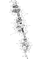
- FIG. 1 is a longitudinal sectional view showing an assembled state of an electric actuator 1 according to an embodiment of the present invention
- FIG. 2 is an external perspective view showing an assembled state of the electric actuator 1
- FIG. FIG. 1 is a longitudinal sectional view showing an assembled state of an electric actuator 1 according to an embodiment of the present invention
- FIG. 2 is an external perspective view showing an assembled state of the electric actuator 1
- FIG. FIG. 1 is a longitudinal sectional view showing an assembled state of an electric actuator 1 according to an embodiment of the present invention
- FIG. 2 is an external perspective view showing an assembled state of the electric actuator 1
- an electric actuator 1 includes a driving unit 2 that generates a driving force, a motion conversion mechanism unit 3 that converts a rotational motion from the driving unit 2 into a linear motion, and a driving unit 2.
- a driving force transmitting unit 4 for transmitting a driving force from the to the motion converting mechanism unit 3, a motion converting mechanism supporting unit 5 for supporting the motion converting mechanism unit 3, an operation unit 6 for outputting the motion of the motion converting mechanism unit 3,
- a lock device 7 for preventing the movement conversion mechanism 3 from being driven.
- the driving force transmission unit 4 corresponds to a rotational motion transmission unit according to the present invention.
- the drive section 2 includes a motor section 8 and a reduction mechanism section 9.
- each part of the electric actuator 1 has a case, and the components are accommodated in each case.
- the motor section 8 has a motor case 11 that houses a driving force generating motor (drive motor 10), and the reduction mechanism section 9 has a reduction gear case 17 that stores a reduction gear mechanism 16.
- the drive motor 10 corresponds to a first motor according to the present invention.
- the driving force transmission unit 4 has a transmission gear case 29 that houses a transmission gear mechanism 28, and the motion conversion mechanism support unit 5 has a bearing case 41 that houses a support bearing 40.
- the motor unit 8 and the speed reduction mechanism unit 9, the speed reduction mechanism unit 9 and the driving force transmission unit 4, and the driving force transmission unit 4 and the motion conversion mechanism support unit 5 are configured to be connected to and separated from each other in each case.
- the shaft case 50 is configured to be connectable and separable from the bearing case 41.
- the motor unit 8 mainly includes a driving motor (for example, a DC motor) 10 for driving the motion conversion mechanism unit 3 and a motor case 11 that houses the driving motor 10.
- the motor case 11 has a cylindrical case body 12 having a bottom and in which the driving motor 10 is housed, and a protruding portion 13 protruding from the bottom 12 a of the case body 12 to the outside.
- the protrusion 13 has a hole 13 a communicating with the internal space of the case body 12.
- the hole 13 a is sealed by a resin sealing member 14 that covers the outer surface of the protrusion 13.
- the drive motor 10 is in a state of being inserted inside from the opening 12 d of the case main body 12. At this time, the end face of the drive motor 10 on the back side in the insertion direction is in contact with the bottom 12 a of the case body 12. A fitting hole 12c is formed at the center of the bottom portion 12a, and the projection 10b on the back side in the insertion direction of the driving motor 10 is fitted into the fitting hole 12c, so that the drive protruding from the projection 10b.
- the rear end (the left end in FIG. 1) of the output shaft 10a of the motor 10 can be prevented from interfering with the bottom 12a of the motor case 11.
- the inner peripheral surface of the peripheral wall portion 12b of the case main body 12 is tapered from the opening 12d side toward the bottom portion 12a side, and is driven when the driving motor 10 is inserted into the case main body 12.
- the outer peripheral surface on the back side in the insertion direction of the motor 10 is configured to contact the inner peripheral surface of the peripheral wall portion 12b.
- the driving motor 10 is supported by the contact with the inner peripheral surface of the case main body 12 and the fitting with the fitting hole 12c in a state of being housed in the case main body 12.
- the case body 12 is provided with a pair of bus bars 15 for connecting the drive motor 10 to a power source.
- One end 15a of each bus bar 15 is connected to the motor terminal 10c by caulking, and the other end 15b is exposed to the outside from the case body 12 (see FIGS. 2 and 3).
- the other end 15b of the bus bar 15 exposed to the outside is connected to a power source.
- the reduction mechanism 9 mainly includes a reduction gear mechanism 16 that reduces and outputs the driving force of the driving motor 10 and a reduction gear case 17 that houses the reduction gear mechanism 16.
- the reduction gear mechanism 16 includes a planetary gear reduction mechanism 18 including a plurality of gears and the like. The detailed configuration of the planetary gear reduction mechanism 18 will be described later.
- the reduction gear case 17 is provided with an accommodation recess 17 a for accommodating the planetary gear reduction mechanism 18 from the side opposite to the drive motor 10.
- a motor adapter 19 is configured to be attachable to the reduction gear case 17.
- the motor adapter 19 is a cylindrical member, and the drive motor 10 is fitted to the motor adapter 19 by inserting a projection 10d on the output side (right side in FIG. 1) of the drive motor 10 into the inner peripheral surface thereof. Fit).
- the reduction gear case 17 is formed with a fitting hole 17b into which the motor adapter 19 is fitted, and the motor adapter 19 is inserted into the fitting hole 17b from the driving motor 10 side.
- a motor adapter 19 is attached.
- the reduction gear case 17 is configured to be fittable to the motor case 11 and is configured to be fittable to a transmission gear case 29 described later disposed on a side opposite to the motor case 11.
- a portion arranged on the motor case 11 side is fitted inside the opening 12 d side of the motor case 11, and a portion arranged on the transmission gear case 29 is fitted externally on the transmission gear case 29.
- the reduction gear case 17 is fastened to the drive motor 10 by bolts 21 (see FIGS. 3 and 7) together with the motor adapter 19 in a state fitted to the motor case 11.
- a mounting groove 17 d for mounting the O-ring 20 is formed on a small-diameter outer peripheral surface of the outer peripheral surface of the reduction gear case 17 that fits with the inner peripheral surface of the motor case 11.
- the motion conversion mechanism 3 is constituted by a ball screw 22 in the present embodiment.
- the ball screw 22 is composed of a ball screw nut 23 as a rotating body, a ball screw shaft 24 as a stroke part that moves linearly, a number of balls 25, and a top 26 as a circulation member.
- Helical grooves 23a and 24a are formed on the inner peripheral surface of the ball screw nut 23 and the outer peripheral surface of the ball screw shaft 24, respectively.
- the space between the spiral grooves 23a and 24a is filled with the ball 25 and the top 26 is incorporated, whereby the two rows of balls 25 circulate.
- an operation unit (actuator head) 6 for operating an operation target is provided at a forward end (left end in FIG. 1) of the ball screw shaft 24 in the forward direction.
- the ball screw nut 23 receives a driving force generated by the driving motor 10 and rotates in either the forward or reverse direction.
- the rotation of the ball screw shaft 24 around the center line X1 is restricted by a rotation restricting portion provided at the rear end (the right end in FIG. 1).
- the driving force transmission unit 4 mainly includes a transmission gear mechanism 28 that transmits driving force and rotational motion from the driving motor 10 included in the driving unit 2 to the ball screw 22 that constitutes the motion conversion mechanism unit 3, and a transmission gear mechanism 28. And a transmission gear case 29 to be accommodated.
- the transmission gear mechanism 28 has a drive gear 30 on the drive side, a driven gear 31 on the driven side that meshes with the drive gear 30, and a gear boss 32.
- the drive gear 30 corresponds to a gear whose rotation is restricted by the lock plate 60 according to the present invention.
- a gear boss 32 is fitted to the center of rotation of the drive gear 30 by press fitting or the like.
- the drive gear 30 is rotatably supported by two rolling bearings 33 and 34 mounted on the transmission gear case 29 and a bearing case 41 described later via the gear boss 32, respectively.
- the driven gear 31 is fixed by being fitted to the outer peripheral surface of the ball screw nut 23 by press fitting or the like.
- the transmission gear case 29 has a housing recess 29 a in which the drive gear 30 and the driven gear 31 are housed.
- An insertion hole 29b for inserting the gear boss 32 is formed in the transmission gear case 29, and a bearing mounting surface 29c on which one rolling bearing 33 for supporting the gear boss 32 is mounted is formed on an inner peripheral surface of the insertion hole 29b. Is formed.
- the transmission gear case 29 has an annular protrusion 29d that fits with the inner peripheral surface of the reduction gear case 17.
- a mounting groove 29e for mounting the O-ring 35 is formed on the outer peripheral surface (fitting surface) of the annular projection 29d.
- the transmission gear case 29 has a groove-like fitting concave portion 29f formed on the surface on the bearing case 41 side for fitting with the bearing case 41.
- the transmission gear case 29 has a cylindrical portion 29g that protrudes toward the tip end of the ball screw shaft 24 (left side in FIG. 1).
- the cylindrical portion 29g is a portion in which the driven gear 31 is accommodated in the transmission gear case 29, and the ball screw 22 is attached thereto so as to cover the periphery of the ball screw shaft 24.
- a boot 36 for preventing foreign matter from entering the transmission gear case 29 is attached between the cylindrical portion 29g and the ball screw shaft 24.
- the boot 36 is made of resin or rubber, and includes a large-diameter end 36a, a small-diameter end 36b, and a bellows portion 36c that extends and contracts in the axial direction by connecting the large-diameter end 36a to the small-diameter end 36b.
- the large-diameter end 36a is fastened and fixed to a mounting portion on the outer peripheral surface of the cylindrical portion 29g by a boot band 37
- the small-diameter end 36b is tightened and fixed to a mounting portion on the outer peripheral surface of the ball screw shaft 24 by a boot band 38.
- the cylindrical portion 29g is provided with a vent hole 29h for ventilating between the inside and the outside of the boot 36 when the boot 36 expands and contracts.
- the motor case 11 is integrally provided with a boot cover 39 disposed around the boot 36.
- the motion conversion mechanism support portion 5 is mainly composed of a support bearing 40 that supports the ball screw 22 that is the motion conversion mechanism portion 3, and a bearing case 41 that houses the support bearing 40.
- the support bearing 40 is formed of a back-to-back double-row angular ball bearing having an outer ring 42, an inner ring 43, and a double-row ball 44 interposed therebetween as main components.
- the support bearing 40 is accommodated in a sleeve 45 formed integrally with the bearing case 41 and is fixed by a retaining ring 46 mounted on the inner peripheral surface of the sleeve 45. Further, the fixed position of the support bearing 40 is press-fitted to the outer peripheral surface of the ball screw nut 23 on the rear end side (the right side in FIG. 1) of the ball screw shaft 24 with respect to the driven gear 31.
- the supporting bearing 40 and the driven gear 31 fixed to the outer peripheral surface of the ball screw nut 23 are axially controlled by a regulating projection 23b provided on the driven gear 31 side of the ball screw nut 23 and a regulating member 47 mounted on the supporting bearing 40 side. Movement is regulated.
- the restricting member 47 is formed of a pair of semicircular members, and is mounted on the outer peripheral surface of the ball screw nut 23 in a state where these members are combined in an annular shape. Further, a collar 48 for holding the regulating member 47 and a retaining ring 49 for preventing the collar 48 from dropping off in the axial direction are mounted on the outer peripheral surface of the ball screw nut 23.
- a ridge portion 41a that fits with the fitting recess 29f of the transmission gear case 29 is provided.
- a gear boss accommodation portion 41b is provided in which a part of the gear boss 32 protruding from the transmission gear case 29 is accommodated in a state where the bearing case 41 is fitted to the transmission gear case 29. I have.
- a bearing mounting surface 41c for mounting a rolling bearing 34 that supports the gear boss 32 is formed on the inner peripheral surface of the gear boss housing portion 41b.
- a bottomed cylindrical shaft case 50 that accommodates the rear end side (the right end side in FIG. 1) of the ball screw shaft 24 is provided with a bolt 51 (see FIG. 3). (See Reference).
- a mounting groove 50 a for mounting the O-ring 52 is formed on a surface of the shaft case 50 that contacts the bearing case 41.
- FIG. 6 is a cross-sectional view of the cross section taken along line AA of FIG. 1 viewed from the direction of arrow A.
- FIG. 7 is an exploded perspective view of the planetary gear reduction mechanism 18.
- the planetary gear reduction mechanism 18 includes a ring gear 55, a sun gear 56, a plurality of planetary gears 57, a planetary gear carrier 58 (see FIG. 1), and a planetary gear holder 59 (see FIG. 1).
- the ring gear 55 has a plurality of convex portions 55a that protrude in the axial direction, and the accommodating concave portions 17a of the reduction gear case 17 are provided with the same number of engaging concave portions 17f as the convex portions 55a (see FIG. 1).
- the ring gear 55 is prevented from rotating relative to the reduction gear case 17 and accommodated therein by incorporating the projection 55a of the ring gear 55 into the engagement recess 17f of the reduction gear case 17 in a phase-matched state.
- a sun gear 56 is disposed at the center of the ring gear 55, and the output shaft 10a of the driving motor 10 is press-fitted into the sun gear 56.
- Each planetary gear 57 is arranged between the ring gear 55 and the sun gear 56 so as to mesh with the ring gear 55 and the sun gear 56.
- Each planet gear 57 is rotatably supported by a planet gear carrier 58 and a planet gear holder 59.
- the planetary gear carrier 58 has a cylindrical portion 58a at the center thereof, and the cylindrical portion 58a is press-fitted between the outer peripheral surface of the gear boss 32 and the inner peripheral surface of the rolling bearing 33 as described above (see FIG. 1). reference).
- An annular collar 75 is mounted between the inner peripheral surface of the other rolling bearing 34 and the outer peripheral surface of the gear boss 32.
- the sun gear 56 connected to the output shaft 10a of the driving motor 10 rotates, and accordingly, each planetary gear 57 rotates. While revolving along the ring gear 55. Then, the planetary gear carrier 58 is rotated by the revolving motion of the planetary gear 57. Thus, the rotational motion of the drive motor 10 is reduced and transmitted to the drive gear 30, and is transmitted to the drive gear 30 in a state where the rotational torque as the driving force is increased. Since the driving force is transmitted through the planetary gear reduction mechanism 18 in this manner, the driving force transmitted to the ball screw shaft 24 and the output of the ball screw shaft 24 can be greatly increased. The size of the motor 10 can be reduced.
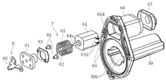
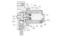
- FIG. 8 is an exploded perspective view of the shaft case 50 and the lock device 7 attached to the shaft case 50.
- FIG. 11 is a cross-sectional view taken along the line DD of FIG. It is.
- the lock device 7 includes a lock plate 60, a slide screw nut 61, a slide screw shaft 62, a fixing plate 63 for fixing the lock plate 60 to the slide screw nut 61, and a lock plate. It mainly includes a lock motor (for example, a DC motor) 64 as a drive source and a spring 65.
- a lock motor for example, a DC motor
- the sliding screw nut 61 and the sliding screw shaft 62 constitute a feed screw portion according to the present invention
- the lock motor 64 corresponds to a second motor according to the present invention
- the spring 65 corresponds to a biasing portion according to the present invention. I do.
- the sliding screw nut 61, the sliding screw shaft 62, the locking motor 64, and the spring 65 constitute an actuator section of the locking device 7 according to the present invention.
- the lock device 7 having the above configuration is assembled, for example, in the following procedure.
- the lock plate 60 is fastened to the sliding screw nut 61 with the bolt 84 (see FIG. 8) via the fixing plate 63.
- the lock motor 64 is housed in a holder 66 provided on the shaft case 50, and the slide screw shaft 62 is attached to an output shaft 64 a of the lock motor 64 protruding from the holder 66.
- a spring 65 is arranged on the outer periphery of the sliding screw shaft 62, and a sliding screw nut 61 to which the lock plate 60 is attached is screwed and mounted on the sliding screw shaft 62.
- the lock plate 60 has a plate shape as a basic shape. As shown in FIG. 9, the lock plate 60 protrudes from the base 601 in a predetermined direction and has a hole 30 a provided in an axial end face 30 b of the drive gear 30. 11 (see FIG. 11), and a pair of contact portions 603, 603 provided on both sides in the width direction of the protrusion 602 (see FIG. 9) and contacting the drive gear 30 in the axial direction. And a pair of notches 604 and 604 provided between the protruding portion 602 and the respective contact portions 603 and 603, and mounting portions 605 and 605 for mounting the lock plate 60 to the fixing plate 63.
- the protruding portion 602 protrudes in the same direction as the advancing / retreating direction Y of the lock plate 60 (see FIG. 9). It is set smaller than the dimension W2 (both refer to FIG. 12A).
- the pair of contact portions 603 each have end surfaces 603a, 603a that can contact the axial end surface 30b of the drive gear 30.
- Each end face 603a is arranged in parallel with the axial end face 30b of the drive gear 30 (see FIG. 12A), and contacts the axial end face 30b of the drive gear 30 when the lock plate 60 advances to a predetermined position.
- the position of each end face 603a is set. Specifically, the end surface 603a of each contact portion 603 is located on the rear side in the direction along the advancing / retreating direction Y of the lock plate 60 with respect to the distal end surface 602a of the protruding portion 602 (see FIG. 9).
- the drive plate 30 contacts the axial end face 30 b of the drive gear 30. (See FIG. 12B), the position of the end surface 603a along the retreating direction Y is set.
- a pair of notches 604 are respectively provided between the protruding portion 602 and each contact portion 603 as shown in FIG.
- Each notch 604 has a shape recessed toward the base 601 from the end surface 603a of each contact portion 603, is connected to the base 601 of the protruding portion 602, and the width dimension increases toward the base 601.
- a first arc portion 606 as an enlarged portion to be formed.
- each notch 604 is connected to the above-described first circular arc portion 606 and the second circular arc portion 607 which is connected to the base 601 side of the first circular arc portion 606 and whose width dimension increases toward the distal end side.
- a straight portion 608 that is connected to the distal end side of the second circular arc portion 607, extends straight toward the distal end side, and is connected to the end surface 603a of the contact portion 603.
- the radius of curvature R1 of the first circular arc portion 606 is larger than the radius of curvature R2 of the second circular arc portion 607.
- the width dimension W3 of the first arc portion 606 is larger than the width dimension W4 of the second arc portion 607 (see FIG.
- the width dimension W3 of the first circular arc portion 606 is preferably set to, for example, 15% or more and 50% or less of the width dimension W1 of the protruding portion 602.
- the first arc portion 606 and the second arc portion 607 are connected at a position where the tangent line is oriented along the width direction. Further, the first arc portion 606 is connected to the protruding portion 602 at a position where the tangent line is oriented along the retreating direction Y, and the second arc portion 607 is connected at a position where the tangent line is oriented along the retreating direction Y. It is connected to the straight part 608.
- the straight portion 608 extends in the same direction as the reciprocating direction Y of the lock plate 60, and is connected to the end surface 603a of the contact portion 603.
- the side surface 602b of the protruding portion 602 is formed in the direction along the retreating direction Y, and the side surface 30a1 of the hole 30a of the drive gear 30 (see FIG. 12A) is formed in the direction along the retreating direction Y. Have been. This allows the side surface 602b of the protrusion 602 and the side surface 30a1 of the hole 30a to come into contact with each other with the protrusion 602 inserted into the hole 30a (see FIG. 12B).
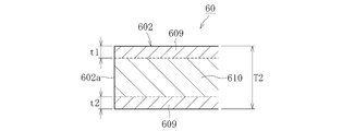
- FIG. 10 is a cross-sectional view when the protruding portion 602 of the lock plate 60 is cut along a virtual plane along the retreating direction Y.
- the protruding portion 602 is formed of two different metal structures, and in the present embodiment, the carbonitrided layer 609 formed on the surface layer and the non-carbonized region excluding the surface layer (remaining portion) are formed. And a hardened layer 610.
- the carbonitrided layer 609 and the non-hardened layer are formed of the same metal, and only the carbonitrided layer 609 has been subjected to carbonitriding.
- the total thickness T1 of the carbonitrided layer 609 (the sum of the thicknesses t1 and t2 of the carbonitrided layers 609 and 609 on both sides in FIG. 10) is 5% of the total thickness T2 of the protruding portion 602. It is adjusted to not less than 50% and preferably not less than 15% and not more than 45%.
- the carbonitrided layer 609 is preferably formed at least on the protruding portion 602 and the enlarged portion (here, the first circular arc portion 606).
- the enlarged portion (first circular arc portion 606) is not shown, but, like the protruding portion 602, is a carbonitrided layer 609 restricted to the surface layer.
- the entire thickness of the carbonitrided layer 609 is adjusted to 5% or more and 50% or less of the total thickness of the enlarged portion.
- the carbonitrided layer 609 may be formed over the entire area of the lock plate 60.
- the lock plate 60 having the above-described configuration is formed by, for example, performing a pressing process such as a punching process on a plate-shaped material having a constant thickness, and then performing a bending process.
- a carbonitriding layer 609 having a predetermined depth (predetermined thickness dimensions t1 and t2) is formed on the surface layer by performing a carbonitriding process.
- the metal of the plate material used at this time is arbitrary, but from the viewpoint of forming the carbonitrided layer 609 only on the surface layer, a metal having a poor heat treatment property (hardenability) is preferable. Such a general-purpose cold steel plate can be suitably used.
- the above example is not intended to exclude a metal having a good heat treatment property (hardenability), but employs any metal as long as the carbonitrided layer 609 can be formed so as to have the thickness dimension ratio T1 / T2 described above. It is possible to do.
- the carbonitrided layer 609 is not necessarily required, and a hardened layer hardened by another heat treatment is used for at least the projecting portion 602 and the enlarged portion of the lock plate 60. It may be formed on the surface layer.
- the holder 66 is formed in a cylindrical shape with a bottom, and a cap 67 is mounted on the opposite side of the bottom 66a.
- the locking motor 64 With the locking motor 64 inserted into the holder 66 and the cap 67 attached, the locking motor 64 contacts the bottom 66 a of the holder 66 and the inner surface of the cap 67.
- the projection 64b on the output side (the left side in FIG. 1) of the lock motor 64 is fitted into the fitting hole 66c formed in the bottom 66a of the holder 66.
- the lock motor 64 is provided in the peripheral wall portion 66b of the holder portion 66. By being inserted, the rotation of the lock motor 64 is regulated. As described above, since the lock motor 64 is accommodated in the holder 66, the lock motor 64 is held by the holder 66, and the entire lock device 7 including the lock motor 64 is held.
- the cap 67 is formed with a hole 67a for inserting a cable 68 connected to the motor terminal 64d of the lock motor 64 (see FIG. 11).
- the holder 66 is provided integrally with the shaft case 50 as a part thereof. However, it is needless to say that the holder 66 is formed separately from the shaft case 50 and attached to the bearing case 41. It doesn't matter.
- Lock device receiving recesses 66d and 41f are formed in a portion of the shaft case 50 where the holder portion 66 is provided and a portion of the bearing case 41 opposed thereto, and penetrate through the lock device receiving recess 41f on the bearing case 41 side. A hole 41g is formed.
- the output shaft 64 a of the locking motor 64 protruding from the holder 66 and the sliding screw shaft are provided in the locking device receiving recesses 66 d and 41 f.
- a sliding screw nut 61, a fixed plate 63, a spring 65, and a part of the lock plate 60 are accommodated.
- the distal end side of the lock plate 60 (here, the base 601 and the protruding portion 602; The part 603 and the notch part 604) are inserted.
- the spring 65 is axially compressed between the bottom 66 a of the holder 66 and the fixed plate 63, and the compressed spring 65 causes the lock plate 60 to move forward. 1 (the left side in FIG. 1).
- the drive gear 30 is disposed in the direction in which the lock plate 60 moves forward, and the drive gear 30 has a hole 30a into which the protrusion 602 of the lock plate 60 can be inserted.
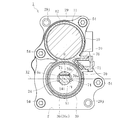
- FIG. 13 which is a cross-sectional view taken along the line FF in FIG. 1 and viewed from the direction of arrow F, holes 30a are provided at a plurality of locations in the circumferential direction of the drive gear 30. .
- the lock plate 60 is inserted into one of these holes 30a, so that when the drive gear 30 rotates, the protrusion 602 and the hole 30a engage to restrict the rotation of the drive gear 30.
- An inclined surface 30c may be formed at the entrance of each hole 30a (see FIG. 13). By forming the hole 30a in this manner, an effect of smoothly inserting the lock plate 60 into the inside of the hole 30a by the inclined surface 30c can be expected.
- a lock sensor 69 for detecting a locked state is mounted on the bearing case 41 (see FIG. 7).
- the lock sensor 69 is a contact-type sensor having a contact 69a formed of an elastic member such as a leaf spring.
- the protrusion 602 is inserted into the hole 30a as the lock plate 60 advances, and the protrusion 602 is When the lock plate 60 is engaged with the lock member 30a (locked state), the lock plate 60 presses the contact 69a to detect the lock state.
- the lock device 7 having the above configuration performs, for example, the operation described below. That is, when power is not supplied to the lock motor 64, the lock plate 60 is held at a position advanced by the spring 65, and as shown in FIG. 12B, the distal end portion (projection portion 602) of the lock plate 60. Are engaged with the hole 30a of the drive gear 30 (locked state).
- power is supplied to the drive motor 10 to start driving the ball screw shaft 24 from this state
- power is also supplied to the lock motor 64, and the lock motor 64 moves the lock plate 60 backward. To drive. Thereby, the sliding screw shaft 62 rotates.
- the rotation of the protrusion 602 of the lock plate 60 is restricted by the through hole 41g of the slide screw nut 61 (see FIG.
- the ball screw shaft 24 is held in a state where it does not advance and retreat. Thereby, even if an external force is input from the operation target side to the ball screw shaft 24 side, the position of the ball screw shaft 24 can be held at a predetermined position.
- the above configuration is particularly suitable for the case where the electric actuator 1 is applied to an application that requires position holding.
- the lock plate 64 is moved backward by driving the lock motor 64.
- the lock motor 64 may be driven to move the lock plate 60 forward. Good.
- the lock plate 60 can be switched between forward and backward. In this case, the spring 65 becomes unnecessary.
- the electric actuator 1 is equipped with a position detection device for detecting the position of the operation unit 6 provided on the ball screw shaft 24 in the stroke direction.
- This position detecting device includes a permanent magnet 73 (see FIG. 1) as a sensor target provided on the ball screw shaft 24 and a boot cover 39 covering the boot 36, a stroke sensor for detecting the position of the permanent magnet 73 in the stroke direction.
- a magnetic sensor 70 is provided (see FIGS. 2 and 3).
- the magnetic sensor 70 is provided on the boot cover 39 formed integrally with the motor case 11. Specifically, as shown in FIG. 14, a portion of the motor case 11 where the drive motor 10 is housed (the case main body 12) and a connection portion between the boot cover 39 and the outside of the motor case 11 are provided. An open sensor case 76 is provided. A sensor base 71 on which two magnetic sensors 70 are mounted is fastened and fixed to the sensor case 76 with bolts 72 (see FIG. 3). As a result, the magnetic sensor 70 faces the ball screw shaft 24 via the boot cover 39.
- the magnetic sensor 70 is positioned radially outward of the ball screw shaft 24 so that the detection surface 70a of the magnetic sensor 70 faces the center line X1 of the ball screw shaft 24 when viewed from the direction shown in FIG. It is arranged in.
- the magnetic sensor 70 is covered with the boot cover 39, the sensor case 76, and the sensor base 71.
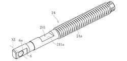
- the permanent magnet 73 is attached to the ball screw shaft 24 at a predetermined circumferential position via the magnet holder 74.
- the permanent magnet 73 faces the drive motor 10 and is perpendicular to the center line X2 (see FIG. 14) of the mating member with the connection hole 6a (circumferential position). It is arranged.
- the notch 241 for fitting and fixing the magnet holder 74 is formed in the ball screw shaft 24 (see FIG. 5), and the direction of the notch 241 (the normal to the flat surface 241a). Direction) is set to be orthogonal to the connection hole 6a.
- the permanent magnet 73 is placed in a direction shifted from the magnetic sensor 70 by 45 ° in the circumferential direction (see FIG. 14).
- any type can be used, and among them, a magnetic sensor such as a Hall IC or a linear Hall IC that can detect the direction and magnitude of a magnetic field using the Hall effect can be suitably used.
- a magnetic sensor of a type that can detect the direction and magnitude of the magnetic field even when the direction of the permanent magnet 73 is circumferentially shifted by 45 ° from the direction directly facing the magnetic sensor 70 as described above is desirable.
- the position detection device configured as described above, when the ball screw shaft 24 advances and retreats, the position of the permanent magnet 73 with respect to the magnetic sensor 70 changes, and accordingly, the magnetic field at the location where the magnetic sensor 70 is disposed also changes. Therefore, by detecting the change of the magnetic field (for example, the direction and strength of the magnetic flux density) by the magnetic sensor 70, the position of the permanent magnet 73 in the stroke direction, and thus the stroke of the operation unit 6 provided on one end side of the ball screw shaft 24. The direction position can be obtained.
- the magnetic field for example, the direction and strength of the magnetic flux density
- a control signal is sent from the controller 81 of the control device 80 to the drive motor 10.
- the target value is, for example, a stroke value calculated by the ECU based on the operation amount when the operation amount is input to the upper ECU of the vehicle.
- the drive motor 10 that has received the control signal starts to rotate, and this driving force is transmitted to the ball screw shaft 24 via the planetary gear reduction mechanism 18, the drive gear 30, the driven gear 31, and the ball screw nut 23.
- the ball screw shaft 24 advances (or retreats) in a direction parallel to the output shaft 10a of the driving motor 10.
- an operation target arranged on the tip end side (actuator head side) of the ball screw shaft 24 and connected via the connection hole 6a is operated.
- the stroke value (axial position) of the ball screw shaft 24 is detected by the magnetic sensor 70.
- the detection value detected by the magnetic sensor 70 is sent to the comparison unit 82 of the control device 80, and the difference between the detection value and the target value is calculated. Then, the driving motor 10 is driven until the detected value becomes equal to the target value.
- the electric actuator 1 of the present embodiment is applied to, for example, Can be reliably controlled.
- the electric actuator 1 has the lock device for restricting the rotation of the drive gear 30 that constitutes the transmission gear mechanism 28 that transmits the rotational motion from the drive motor 10 to the motion conversion mechanism 3.
- the lock device 7 has a lock plate 60 and an actuator unit for moving the lock plate 60 forward or backward with respect to the drive gear 30.
- the lock plate 60 has a protruding portion 602 that can be inserted into the hole 30a provided in the axial end surface 30b of the drive gear 30, and end surfaces 603a and 603a that can contact the axial end surface 30b of the drive gear 30.
- a pair of notches 604 recessed toward the base 601 from the end surface 603a of each of the contact portions 603 is provided between the pair of contact portions 603 and 603, and each of the notches 604 protrudes.
- a first arc portion 606 is provided as an enlarged portion which is connected to the base 601 side of the portion 602 and whose width dimension increases toward the base 601 side.
- the lock plate 60 By determining the shape of the lock plate 60 in this manner, when engaging with the drive gear 30 (see FIG. 12B), it is possible to avoid the situation where the notch 604 becomes the starting point of stress concentration, and to prevent the notch 604 from becoming a stress concentration.
- One circular arc portion 606 can be made large. Thereby, the strength of the protruding portion 602 against the load received from the direction of engagement with the drive gear 30 can be increased. Further, since the notch 604 is provided between the protruding portion 602 and each contact portion 603, the end face 603a of the contact portion 603 is not affected by the creation of the notch 604 at all. , Can maintain the current position.
- the strength of the lock plate 60 is improved when the rotation of the drive gear 30 is restricted, and the excessive advance of the lock plate 60 is restricted by the end face 603a (FIG. 12C). ), It is possible to prevent the lock plate 60 from biting into the drive gear 30.
- the protruding portion 602 and the enlarged portion (first arc portion 606) of the lock plate 60 are formed of a predetermined metal, and the carbonitrided layer 609 of the predetermined metal is provided on the surface layer of the protruding portion 602. Formed (see FIG. 10).
- the carbonitrided layer 609 serving as a hardened layer can be formed at a very shallow depth (several hundreds ⁇ m or less) from the surface, so that the protrusion 602 and the enlarged portion can be formed without performing post-processing.
- the ratio of the total thickness T1 of the hardened layer (carbonitrided layer 609) to the total thickness T2 of the substrate can be suppressed to 50% or less.
- the notch 604 includes a first arc portion 606 as an enlarged portion having a relatively large radius of curvature R1, a second arc portion 607 having a relatively small radius of curvature R2, and a straight portion 608.
- the cutout portion 604 can take a form other than the above.
- the enlarged portion is not limited to the arc shape, and is formed of an arbitrary curved surface portion, a tapered surface portion, a straight portion, or a combination thereof as long as the widthwise dimension W3 increases toward the base 601 side. It is also possible.
- the region of the notch portion 604 excluding the enlarged portion can be formed of an arbitrary curved surface portion, a tapered surface portion, a straight portion, or a combination thereof.
- the configuration is exemplified in which the hole 30a is provided in the axial end face 30b of the drive gear 30 constituting the transmission gear mechanism 28, and the projection 602 of the lock plate 60 can be inserted into the hole 30a.
- other configurations can of course be employed.
- a hole is provided in the axial end surface of the driven gear 31 that forms the transmission gear mechanism 28 together with the drive gear 30 as long as a space problem is allowed, and the protrusion of the lock plate 60 is formed in this hole. It is also possible to adopt a configuration in which the 602 can be inserted.
- the motion conversion mechanism 3 is not limited to the ball screw 22, but may be a sliding screw device. However, from the viewpoint of reducing the rotational torque and reducing the size of the driving motor 10, the ball screw 22 is more preferable.
- the configuration using the double-row angular ball bearing is exemplified as the support bearing 40 that supports the motion conversion mechanism unit 3. However, the configuration is not limited thereto, and a pair of single-row angular ball bearings may be used. They may be used in combination. Further, the support bearing 40 is not limited to an angular contact ball bearing, and it is also possible to apply another double row bearing using, for example, a deep groove ball bearing.
- the reduction mechanism 9 may be a reduction mechanism other than the planetary gear reduction mechanism 18. Further, by changing the gear ratio between the drive gear 30 and the driven gear 31, the driving force transmission unit 4 may also function as a reduction mechanism.
- the electric actuator 1 having both the speed reduction mechanism 9 and the lock device 7 has been exemplified, but an electric actuator having only the lock device 7 may be configured.
Abstract
ロックプレート60は、回転運動を第一モータ10から運動変換機構部4に伝達する伝達ギヤ機構28を構成するギヤ30の回転を規制するためのロックプレートであって、基部601と、基部601から突出し、ギヤ30の軸方向端面30bに設けられた穴部30aに挿入可能な突出部602と、突出部602の幅方向両側に設けられ、それぞれギヤ30の軸方向端面30bと当接可能な端面603aを有する一対の当接部603とを備える。突出部602と各々の当接部603との間に、各々の当接部603の端面603aよりも基部601側に凹んだ一対の切欠き部604が設けられ、各々の切欠き部604は、突出部602の基部601側とつながり、基部601側に向かうにつれて幅方向寸法W3が拡大する拡大部606を有する。
Description
本発明は、ロックプレートとこのプレートを備えたロック装置、並びにこのロック装置を備えた電動アクチュエータに関する。
近年、車両等の省力化、低燃費化を目的とした電動化が進んでおり、例えば、自動車の自動変速機やブレーキ、ステアリング等の操作をモータなど電動機の力で行うシステムが開発され、市場に投入されている。このような用途に使用されるアクチュエータとして、電動機の回転運動を直線方向の運動に変換するボールねじ機構を用いた電動アクチュエータが知られている(特許文献1を参照)。
また、更なる小型化を図るために、例えば特許文献2には、モータ、減速機、及びボールねじ機構を所定の態様で組み合わせてなる電動アクチュエータが提案されている。このアクチュエータには、当該アクチュエータの駆動停止時、出力側からボールねじに外力等が作用した際にボールねじが動作(誤動作)する事態を防止するためのロック機構が設けられている。このロック機構は、モータの駆動力をボールねじ機構に伝達するためのギヤ(例えばドライブギヤ)に設けた穴部に、プレート状をなすロック部材(ロックプレート)の突出部を挿入して、ドライブギヤの回転を規制する構成を成している。
このように、ロック機構を構成するロックプレートは、その突出部を直接ドライブギヤの穴部に挿入して当該穴部の側面と係合させることでドライブギヤの回転を規制している。そのため、ロックプレートには、ギヤの回転に伴いギヤから受ける荷重(例えば衝撃荷重)に対する高い強度が求められる。しかしながら、この種の電動アクチュエータにおいては、複数の要素を限られたスペース内に密集して配置していることから、単にロックプレートの厚み寸法や幅方向寸法(ここでいう幅方向とは、厚み方向と突出部の突出方向の何れにも直交する向きをいう。以下、本明細書において同じ。)を大きくすることは、サイズの制約上難しい。
以上の事情に鑑み、本明細書では、ロックプレートのサイズを大きくすることなく、当該ロックプレートの強度を向上することを、解決すべき技術課題とする。
前記課題の解決は、本発明に係るロックプレートによって達成される。すなわちこのロックプレートは、第一モータの駆動により生じた回転運動を、運動変換機構部により所定の運動に変換して出力する電動アクチュエータに組み込まれ、回転運動を第一モータから運動変換機構部に伝達する伝達ギヤ機構を構成するギヤの回転を規制するためのロックプレートであって、基部と、基部から突出し、ギヤの軸方向端面に設けられた穴部に挿入可能な突出部と、突出部の幅方向両側に設けられ、それぞれギヤの軸方向端面と当接可能な端面を有する一対の当接部とを備え、突出部と各々の当接部との間に、各々の当接部の端面よりも基部側に凹んだ一対の切欠き部が設けられ、各々の切欠き部は、突出部の基部側とつながり、基部側に向かうにつれて幅方向寸法が拡大する拡大部を有する点をもって特徴付けられる。
通常、板状の部材に対して切欠き部は応力集中の起点となるため、強度向上のために切欠き部を設けることはない。これに対して、本発明では、突出部とその幅方向外側に位置する当接部との間に、基部側(突出側とは反対の側)に向けて凹んだ形態の切欠き部を設けるようにした。この向きに凹んだ切欠き部であれば、ギヤの回転に伴い突出部がギヤから受ける荷重に対して応力集中の起点となるおそれは小さい。そのため、この切欠き部のうち突出部の基端部とつながる部分に、幅方向寸法が拡大する拡大部を設ける構成をとることで、拡大部を大きくとることができ、これによりギヤから受ける荷重に対する突出部の強度を高めることができる。また、この拡大部(切欠き部)は、突出部と当接部との間に設けられることから、当接部の端面は、切欠き部の創設によって何らの影響を受けることなく、現行の位置を維持できる。以上より、本発明に係るロックプレートによれば、ギヤの回転規制時におけるロックプレートの強度向上を図ると共に、当該端面でロックプレートの過度な前進を規制して、ロックプレートのギヤへの噛み込みを防止することが可能となる。
また、本発明に係るロックプレートにおいて、拡大部は円弧形状をなす第一円弧部であってもよい。
このように、拡大部を円弧形状の第一円弧部とすることによって、断面積の急激な変化を抑制することができる。よって、突出部の基端側における応力集中をより効果的に緩和して、ロックプレートの更なる強度向上を図ることが可能となる。
また、本発明に係るロックプレートにおいて、各々の切欠き部は、拡大部と、拡大部の基部側とつながり、先端側に向かうにつれて幅方向寸法が拡大する第二円弧部とを有してもよい。
このように、各々の切欠き部に、拡大部の基端側とつながり、先端側に向かうにつれて幅方向寸法が拡大する第二円弧部をさらに設けることにより、切欠き部の表面(側面)を滑らかにつなぐことができる。よって、切欠き部としての強度、ひいてはロックプレートの強度をさらに向上させることが可能となる。
また、各々の切欠き部が第二円弧部を有する場合、本発明に係るロックプレートにおいて、各々の切欠き部は、第二円弧部の先端側とつながり、先端側に向けてストレートに伸びて当接部の端面とつながるストレート部をさらに有してもよい。
このように当接部の端面と、第二円弧部(の側面)とをストレート部でつないだ形態とすることで、切欠き部の表面(側面)をより滑らかにつなぐことができる。また、上記構成によれば、当接部の断面積が一定になる(ネック部が存在しない)ので、当接部の強度向上を図ることもできる。
また、本発明に係るロックプレートにおいて、突出部の側面は、穴部の側面と平行であってもよい。
このように突出部の側面と、ギヤの穴部の側面とを平行にすることで、穴部に突出部を挿入した状態で、穴部の側面と突出部の側面とを対向領域の全面で当接させることができる。言い換えると、突出部の先端と穴部とが片当たりする事態を回避することができる。これにより、ギヤから受ける面圧を下げることができるので、局所的な負荷に起因した応力集中を回避することができる。
また、本発明に係るロックプレートにおいて、少なくとも突出部及び拡大部は所定の金属で形成されると共に、突出部及び拡大部の表層には所定の金属の浸炭窒化層が形成され、浸炭窒化層の全厚み寸法が、突出部及び拡大部の全厚み寸法の5%以上でかつ50%以下に調整されていてもよい。
本発明に係るロックプレートは板状をその基本形状とするものであるから、突出部やその基端側(拡大部)もまた板状をなす。ここで、本発明では、突出部及び拡大部を所定の金属で形成すると共に、突出部及び拡大部の表層に上記所定の金属の浸炭窒化層を形成した。また、この際、浸炭窒化層の全厚み寸法が、突出部及び拡大部の全厚み寸法の5%以上でかつ50%以下となるようにした。浸炭窒化処理であれば、表面から非常に浅い深さ(数百μm以下)に硬化層となる浸炭窒化層を形成することができるので、突出部及び拡大部の全厚み寸法に対する硬化層の全厚み寸法の比率を50%以下に抑えることができる。これにより最低限の硬化層(5%)を確保しつつも、未硬化の領域(突出部及び拡大部のうち浸炭窒化層を除いた領域)を相当程度維持することにより、全体として強度とじん性の双方に優れたロックプレートにすることが可能となる。
以上の説明に係るロックプレートは、全体として薄肉形状でありながら高い強度を発揮し得るものであるから、例えば上記構成のロックプレートと、このロックプレートをギヤに対して前進又は後退させるアクチュエータ部とを備えたロック装置として好適に提供可能である。
また、本発明に係るロック装置において、アクチュエータ部は、第二モータと、第二モータの回転駆動力を受けてロックプレートを後退させる送りねじ部と、ロックプレートを前進する向きに付勢する付勢部とを有してもよい。
このようにアクチュエータ部を構成することによって、電力供給時にはロックプレートを後退させることで、突出部がギヤの穴部から退避した状態となるので、ギヤの回転が許容される。また、電力供給の遮断時には付勢部によりロックプレートが前進する向きに付勢され、ギヤの穴部にロックプレートの突出部が挿入されることでギヤの回転が規制される。以上より、このロック装置が組み込まれる電動アクチュエータの駆動時、すなわちギヤの回転が必要な場合には、当該電動アクチュエータに供給される電力を利用してロックプレートを後退させることができ、電動アクチュエータの駆動停止時、すなわちギヤの回転を規制する必要がある場合には、当該電動アクチュエータへの電力供給が遮断されるので、何らの別電源を必要とせず自動的にロックプレートを前進させて、ギヤの回転を規制することが可能となる。
以上の説明に係るロック装置は、例えば上記構成のロック装置と、第一モータと、運動変換機構部と、伝達ギヤ機構とを備えた電動アクチュエータとして好適に提供可能である。
本発明によれば、ロックプレート全体のサイズを大きくすることなく、当該ロックプレートの強度を向上することができる。
以下、添付の図面に基づき、本発明について説明する。なお、本発明を説明するための各図面において、同一の機能もしくは形状を有する構成要素については、判別が可能な限り同一符号を付すことにより一度説明した後ではその説明を省略する。
図1は、本発明の一実施形態に係る電動アクチュエータ1の組み立て状態を示す縦断面図、図2は、電動アクチュエータ1の組み立て状態を示す外観斜視図、図3は、電動アクチュエータ1の分解斜視図である。
図1に示すように、本実施形態に係る電動アクチュエータ1は、駆動力を発生させる駆動部2と、駆動部2からの回転運動を直線運動に変換する運動変換機構部3と、駆動部2から運動変換機構部3へ駆動力を伝達する駆動力伝達部4と、運動変換機構部3を支持する運動変換機構支持部5と、運動変換機構部3の運動を出力する操作部6と、運動変換機構部3の駆動を防止するロック装置7とを備える。ここで、駆動力伝達部4が、本発明に係る回転運動伝達部に相当する。駆動部2は、モータ部8と減速機構部9とで構成されている。
上記電動アクチュエータ1を構成する各部分は、それぞれケースを有し、各ケース内に構成部品が収容されている。具体的に、モータ部8は、駆動力発生用のモータ(駆動用モータ10)を収容するモータケース11を有し、減速機構部9は、減速ギヤ機構16を収容する減速ギヤケース17を有する。ここで、駆動用モータ10が、本発明に係る第一モータに相当する。また、駆動力伝達部4は、伝達ギヤ機構28を収容する伝達ギヤケース29を有し、運動変換機構支持部5は、支持軸受40を収容する軸受ケース41を有する。本実施形態では、モータ部8と減速機構部9、減速機構部9と駆動力伝達部4、駆動力伝達部4と運動変換機構支持部5は、互いにケースごと連結分離可能に構成されている。さらに、軸受ケース41に対しては、軸ケース50が連結分離可能に構成されている。以下、電動アクチュエータ1を構成する各部の詳細な構成について説明する。
モータ部8は主に、運動変換機構部3を駆動させるための駆動用モータ(例えばDCモータ)10と、駆動用モータ10を収容するモータケース11とで構成されている。モータケース11は、本実施形態では内部に駆動用モータ10が収容される有底円筒状のケース本体12と、ケース本体12の底部12aから外部に突出する突出部13とを有する。突出部13は、ケース本体12の内部空間と連通する孔部13aが形成されている。この孔部13aは、突出部13の外面を覆う樹脂製の封止部材14によって封止されている。
駆動用モータ10は、ケース本体12の開口部12dから内部に挿入された状態にある。この際、駆動用モータ10の挿入方向奥側の端面がケース本体12の底部12aに当接している。また、底部12aの中央部には嵌合孔12cが形成されており、この嵌合孔12cに駆動用モータ10の挿入方向奥側の突起10bが嵌合することで、突起10bから突出する駆動用モータ10の出力軸10aの後端(図1の左端部)がモータケース11の底部12aと干渉する事態を回避可能としている。さらに、ケース本体12の周壁部12bの内周面は、開口部12d側から底部12a側に向かってテーパ状に縮径しており、駆動用モータ10がケース本体12内に挿入されると駆動用モータ10の挿入方向奥側の外周面が周壁部12bの内周面に接触するように構成されている。このように、駆動用モータ10は、ケース本体12内に収容された状態で、ケース本体12の内周面との接触と嵌合孔12cとの嵌合によって支持される。
また、モータケース11を開口部12d側から見た図4に示すように、ケース本体12には、駆動用モータ10を動力電源に接続するための一対のバスバー15が取り付けられている。各バスバー15の一端部15aはモータ端子10cに対して加締めることで接続され、他端部15bはケース本体12から外部に露出している(図2、図3を参照)。この外部に露出するバスバー15の他端部15bが動力電源に接続される。
図1に示すように、減速機構部9は主に、駆動用モータ10の駆動力を減速して出力する減速ギヤ機構16と、減速ギヤ機構16を収容する減速ギヤケース17とで構成されている。減速ギヤ機構16は、複数の歯車等からなる遊星歯車減速機構18で構成される。遊星歯車減速機構18の詳細な構成については後述する。
減速ギヤケース17には、遊星歯車減速機構18を駆動用モータ10とは反対の側から収容するための収容凹部17aが設けられている。また、減速ギヤケース17には、モータアダプタ19が取付け可能に構成されている。モータアダプタ19は筒状の部材で、その内周面に駆動用モータ10の出力側(図1の右側)の突起10dが挿入されることでモータアダプタ19に駆動用モータ10が嵌合(内嵌)されている。減速ギヤケース17には、モータアダプタ19が嵌合される嵌合孔17bが形成されており、この嵌合孔17bに対してモータアダプタ19を駆動用モータ10側から挿入することで減速ギヤケース17にモータアダプタ19が取り付けられている。
減速ギヤケース17は、モータケース11に対して嵌合可能に構成されると共に、モータケース11とは反対の側に配置される後述の伝達ギヤケース29に対して嵌合可能に構成されている。減速ギヤケース17のうち、モータケース11側に配置される部分がモータケース11の開口部12d側に内嵌されると共に、伝達ギヤケース29側に配置される部分が伝達ギヤケース29に外嵌されている。この場合、減速ギヤケース17は、モータケース11に対して嵌合された状態でモータアダプタ19と一緒にボルト21(図3、図7を参照)によって駆動用モータ10に締結される。減速ギヤケース17の駆動用モータ10側には、減速ギヤケース17とモータケース11とが嵌合された状態で、駆動用モータ10から突出するモータ端子10c及びこのモータ端子10cに加締められた状態のバスバー15の一端部15aと減速ギヤケース17との干渉を回避するための凹部17cが形成されている。また、減速ギヤケース17の外周面のうちモータケース11の内周面と嵌合する小径外周面には、Oリング20を装着するための装着溝17dが形成されている。
運動変換機構部3は、本実施形態ではボールねじ22で構成される。ボールねじ22は、回転体としてのボールねじナット23と、直線運動するストローク部であるボールねじ軸24と、多数のボール25、及び循環部材としてのこま26とで構成されている。ボールねじナット23の内周面とボールねじ軸24の外周面にそれぞれ螺旋状溝23a,24aが形成されている。両螺旋状溝23a,24aの間にボール25が充填され、こま26が組み込まれ、これにより2列のボール25が循環する。この場合、ボールねじ軸24の前進方向の先端部(図1の左端部)に、操作対象を操作する操作部(アクチュエータヘッド)6が設けられている。
ボールねじナット23は、駆動用モータ10で発生させた駆動力を受けて正逆何れかの方向に回転する。一方、ボールねじ軸24は、その後端部(図1の右端部)に設けられた回転規制部によって中心線X1まわりの回転が規制された状態にある。
駆動力伝達部4は主に、駆動部2が有する駆動用モータ10から運動変換機構部3を構成するボールねじ22へ駆動力及び回転運動を伝達する伝達ギヤ機構28と、伝達ギヤ機構28を収容する伝達ギヤケース29とで構成されている。伝達ギヤ機構28は、駆動側のドライブギヤ30と、これと噛み合う従動側のドリブンギヤ31、及びギヤボス32を有する。ここで、ドライブギヤ30が、本発明に係るロックプレート60により回転規制の対象となるギヤに相当する。
ドライブギヤ30の回転中心部にはギヤボス32が圧入等により嵌合されている。ドライブギヤ30は、このギヤボス32を介して伝達ギヤケース29と後述する軸受ケース41それぞれに装着される2つの転がり軸受33,34によって回転可能に支持されている。一方、ドリブンギヤ31は、ボールねじナット23の外周面に圧入等により嵌合されることで固定されている。駆動用モータ10からの駆動力が遊星歯車減速機構18を介してドライブギヤ30に伝達されると、ドライブギヤ30とドリブンギヤ31との噛み合いにより上記駆動力がドリブンギヤ31に伝達される。これによりドリブンギヤ31とボールねじナット23が一体的に回転し、ボールねじ軸24がその長手方向に沿って前進又は後退する。
伝達ギヤケース29は、ドライブギヤ30およびドリブンギヤ31が収容される収容凹部29aを有する。また、伝達ギヤケース29には、ギヤボス32を挿通するための挿通孔29bが形成され、挿通孔29bの内周面には、ギヤボス32を支持する一方の転がり軸受33が装着される軸受装着面29cが形成されている。また、伝達ギヤケース29は、減速ギヤケース17の内周面と嵌合する環状突起29dを有する。この環状突起29dの外周面(嵌合面)には、Oリング35を装着するための装着溝29eが形成されている。また、伝達ギヤケース29の軸受ケース41側の面には、軸受ケース41と嵌合する溝状の嵌合凹部29fが形成されている。
また、伝達ギヤケース29は、ボールねじ軸24の先端部側(図1の左側)へ突出する円筒部29gを有する。この円筒部29gは、伝達ギヤケース29内にドリブンギヤ31が収容され、これにボールねじ22が組み付けられた状態で、ボールねじ軸24の周囲を覆うように配置される部分である。円筒部29gとボールねじ軸24の間には、伝達ギヤケース29内への異物侵入を防止するブーツ36が取り付けられる。ブーツ36は樹脂製又はゴム製であり、大径端部36aと、小径端部36bと、大径端部36aを小径端部36bにつないで軸方向に伸縮する蛇腹部36cとで構成されている。大径端部36aが円筒部29gの外周面の取付け部位にブーツバンド37によって締め付け固定され、小径端部36bがボールねじ軸24の外周面の取付け部位にブーツバンド38によって締め付け固定される。円筒部29gには、ブーツ36が伸縮したときにブーツ36の内側と外側との間で通気を行うための通気孔29hが設けられている。また、上記モータケース11には、ブーツ36の周囲に配置されるブーツカバー39が一体に設けられている。
運動変換機構支持部5は主に、運動変換機構部3であるボールねじ22を支持する支持軸受40と、支持軸受40を収容する軸受ケース41とで構成されている。支持軸受40は、本実施形態では、外輪42と内輪43とこれらの間に介在する複列のボール44を主要な構成要素とする背面合わせの複列アンギュラ玉軸受で構成される。
支持軸受40は、軸受ケース41と一体に形成されたスリーブ45内に収容され、スリーブ45の内周面に装着された止め輪46で固定されている。また、支持軸受40の固定位置は、ボールねじナット23の外周面に対して上記ドリブンギヤ31よりもボールねじ軸24の後端側(図1の右側)に圧入嵌合されている。ボールねじナット23の外周面に固定される支持軸受40とドリブンギヤ31は、ボールねじナット23のドリブンギヤ31側に設けられた規制突起23bと、支持軸受40側に装着された規制部材47によって軸方向の移動が規制される。規制部材47は、一対の半円弧状部材で構成され、これらを環状に組み合わせた状態でボールねじナット23の外周面に装着される。さらに、ボールねじナット23の外周面には、規制部材47を保持する押さえ用カラー48と、この押さえ用カラー48の軸方向の脱落を防止する止め輪49が装着される。
軸受ケース41の伝達ギヤケース29側には、伝達ギヤケース29の嵌合凹部29fと嵌合する突条部41aが設けられている。また、軸受ケース41の伝達ギヤケース29側には、軸受ケース41が伝達ギヤケース29と嵌合した状態で、伝達ギヤケース29から突出するギヤボス32の一部が収容されるギヤボス収容部41bが設けられている。このギヤボス収容部41bの内周面には、ギヤボス32を支持する転がり軸受34を装着するための軸受装着面41cが形成されている。
軸受ケース41の伝達ギヤケース29側とは反対側には、ボールねじ軸24の後端部側(図1の右端部側)を収容する有底筒状の軸ケース50がボルト51(図3を参照)で締結可能に構成されている。軸ケース50の軸受ケース41との当接面には、Oリング52を装着するための装着溝50aが形成されている。
図3に示すように、上記モータケース11、減速ギヤケース17、伝達ギヤケース29、軸受ケース41の各ケースの半径方向外側周辺には、これらを組み立て締結するためのボルト54を挿通するボルト挿通孔11a,17e,29i,41dが設けられている。さらに、伝達ギヤケース29と軸受ケース41の両方の半径方向外側周辺には、組立てられた電動アクチュエータ1を所定の設置箇所に取付けるための貫通孔29j,41eが設けられている。
ここで、図1、図6、及び図7に基づき遊星歯車減速機構18について説明する。図6は、図1のA-A線に沿った断面を矢印Aの向きから見た横断面図、図7は、遊星歯車減速機構18の分解斜視図である。
遊星歯車減速機構18は、リングギヤ55と、サンギヤ56と、複数の遊星ギヤ57と、遊星ギヤキャリア58(図1を参照)と、遊星ギヤホルダ59(図1を参照)から構成される。リングギヤ55は、軸方向に突出する複数の凸部55aを有し、減速ギヤケース17の収容凹部17aには凸部55aと同数の係合凹部17fが設けられている(図1を参照)。減速ギヤケース17の係合凹部17fにリングギヤ55の凸部55aを位相合わせした状態で組み込むことにより、リングギヤ55が減速ギヤケース17に対して回り止めされて収容されている。
リングギヤ55の中央にサンギヤ56が配置され、サンギヤ56には駆動用モータ10の出力軸10aが圧入嵌合される。また、リングギヤ55とサンギヤ56との間には各遊星ギヤ57がこれらリングギヤ55及びサンギヤ56と噛み合うように配置されている。各遊星ギヤ57は、遊星ギヤキャリア58と遊星ギヤホルダ59によって回転可能に支持されている。遊星ギヤキャリア58はその中央部に円筒部58aを有し、円筒部58aは上述の如くギヤボス32の外周面と転がり軸受33の内周面との間に圧入嵌合されている(図1を参照)。なお、他方の転がり軸受34の内周面とギヤボス32の外周面との間には、環状のカラー75が装着されている。
上記の如く構成された遊星歯車減速機構18は、駆動用モータ10が回転駆動すると、駆動用モータ10の出力軸10aに連結されたサンギヤ56が回転し、これに伴って各遊星ギヤ57が自転しながらリングギヤ55に沿って公転する。そして、この遊星ギヤ57の公転運動により遊星ギヤキャリア58が回転する。これより、駆動用モータ10の回転運動が減速されてドライブギヤ30に伝達されると共に、駆動力としての回転トルクが増加した状態でドライブギヤ30に伝達される。このように、遊星歯車減速機構18を介して駆動力が伝達されることで、ボールねじ軸24に伝達される駆動力、ひいてはボールねじ軸24の出力が大きく得られるようになるので、駆動用モータ10の小型化を図ることが可能となる。
続いて、図1、図8~図12Cに基づき、ロック装置7の詳細を説明する。まずロック装置7の全体構成を説明し、次いでロック装置7を構成するロックプレート60の構成を説明する。
図8は、軸ケース50と、この軸ケース50に取り付けられるロック装置7の分解斜視図、図11は、図1のD-D線に沿った断面を矢印Dの向きから見た横断面図である。これらの図に示すように、ロック装置7は、ロックプレート60と、滑りねじナット61と、滑りねじ軸62と、ロックプレート60を滑りねじナット61に固定するための固定板63と、ロック用駆動源としてのロック用モータ(例えばDCモータ)64と、ばね65とを主に備える。ここで、滑りねじナット61と滑りねじ軸62が本発明に係る送りねじ部を構成し、ロック用モータ64が本発明に係る第二モータ、ばね65が本発明に係る付勢部にそれぞれ相当する。また、これら滑りねじナット61と滑りねじ軸62、ロック用モータ64、及びばね65とで本発明に係るロック装置7のアクチュエータ部が構成される。
上記構成のロック装置7は例えば以下の手順で組み立てられる。まず、ロックプレート60を、滑りねじナット61に対して固定板63を介してボルト84(図8を参照)で締結する。次いで、ロック用モータ64を、軸ケース50に設けられたホルダ部66内に収容し、ホルダ部66から突出するロック用モータ64の出力軸64aに滑りねじ軸62を取り付ける。そして、滑りねじ軸62の外周にばね65を配置すると共に、ロックプレート60が取り付けられた滑りねじナット61を滑りねじ軸62に対して螺合して装着する。このようにして、ロック装置7の組み立てが完了する。
ロックプレート60は、板状を基本形状とするもので、図9に示すように、基部601と、基部601から所定の向きに突出し、ドライブギヤ30の軸方向端面30bに設けられた穴部30a(図11を参照)に挿入可能な突出部602と、突出部602の幅方向両側に設けられ(図9を参照)、ドライブギヤ30とその軸方向で当接する一対の当接部603,603と、突出部602と各当接部603,603との間にそれぞれ設けられる一対の切欠き部604,604、及び固定板63にロックプレート60を取付けるための取付け部605,605とを備える。
突出部602は、本実施形態では、ロックプレート60の進退方向Yと同じ向きに突出しており(図9を参照)、その幅方向寸法W1は、後述するドライブギヤ30の穴部30aの幅方向寸法W2(ともに図12Aを参照)よりも小さく設定される。
一対の当接部603は、それぞれドライブギヤ30の軸方向端面30bと当接可能な端面603a,603aを有する。各端面603aは、ドライブギヤ30の軸方向端面30bと平行に配置され(図12Aを参照)、ロックプレート60が所定の位置まで前進した際にドライブギヤ30の軸方向端面30bと当接するよう、各端面603aの位置が設定される。具体的には、各当接部603の端面603aは、突出部602の先端面602aよりもロックプレート60の進退方向Yに沿った向きで後方側に位置しており(図9を参照)、ロックプレート60の前進に伴い、後述する切欠き部604の拡大部(ここでは第一円弧部606)とドライブギヤ60とが係合する前に、ドライブギヤ30の軸方向端面30bと当接するよう(図12Bを参照)、端面603aの進退方向Yに沿った位置が設定される。
一対の切欠き部604はそれぞれ、図9に示すように、突出部602と各当接部603との間に設けられる。各切欠き部604は、各当接部603の端面603aよりも基部601側に凹んだ形状をなしており、突出部602の基部601側とつながり、基部601側に向かうにつれて幅方向寸法が拡大する拡大部としての第一円弧部606を有する。
本実施形態では、各切欠き部604は、上述した第一円弧部606と、第一円弧部606の基部601側とつながり、先端側に向かうにつれて幅方向寸法が拡大する第二円弧部607と、第二円弧部607の先端側とつながり、先端側に向けてストレートに伸びて当接部603の端面603aとつながるストレート部608とを有する。この場合、第一円弧部606の曲率半径R1は、第二円弧部607の曲率半径R2よりも大きい。また、第一円弧部606の幅方向寸法W3は、第二円弧部607の幅方向寸法W4よりも大きい(図12Aを参照)。また、突出部602との関係でいえば、第一円弧部606の幅方向寸法W3は、例えば突出部602の幅方向寸法W1の15%以上で50%以下に設定されるのがよい。
本実施形態では、接線が幅方向に沿った向きとなる位置で第一円弧部606と第二円弧部607とがつながっている。また、第一円弧部606は、接線が進退方向Yに沿った向きとなる位置で突出部602とつながっており、第二円弧部607は、接線が進退方向Yに沿った向きとなる位置でストレート部608とつながっている。ストレート部608は、ロックプレート60の進退方向Yと同じ向きに伸びて、当接部603の端面603aにつながっている。
また、突出部602の側面602bは、進退方向Yに沿った向きに形成されると共に、ドライブギヤ30の穴部30aの側面30a1(図12Aを参照)は、進退方向Yに沿った向きに形成されている。これにより、突出部602を穴部30aに挿入した状態で、突出部602の側面602bと、穴部30aの側面30a1との面当たりを可能にしている(図12Bを参照)。また、上述のように、突出部602の側面602bが進退方向Yに沿った向きに形成される場合、各当接部603の端面603aは、突出部602の側面602bと直交する向きに形成される。
図10は、ロックプレート60の突出部602を進退方向Yに沿った仮想平面で切断した際の断面図である。図10に示すように、突出部602は、二つの異なる金属組織で構成されており、本実施形態では、表層に形成された浸炭窒化層609と、表層を除く領域(残部)を構成する非硬化層610とから成っている。浸炭窒化層609と非硬化層は同一の金属で形成されており、浸炭窒化層609のみに浸炭窒化処理が施された状態となっている。この場合、浸炭窒化層609の全厚み寸法T1(図10でいえば表裏双方の浸炭窒化層609,609の各厚み寸法t1,t2の総和)が、突出部602の全厚み寸法T2の5%以上でかつ50%以下に調整され、好ましくは15%以上でかつ45%以下に調整される。なお、浸炭窒化層609は少なくとも突出部602と拡大部(ここでは第一円弧部606)とに形成されていることが好ましい。この場合、拡大部(第一円弧部606)は、図示は省略するが、突出部602と同様、表層に規制された浸炭窒化層609と。非硬化層610とから成り、浸炭窒化層609の全厚み寸法が、拡大部の全厚み寸法の5%以上でかつ50%以下に調整される。もちろん、浸炭窒化層609は、ロックプレート60の全域にわたって形成されてもよい。
上記構成のロックプレート60は、例えば板厚一定の板状素材に対して打ち抜き等のプレス加工を施した後、曲げ加工を施すことにより成形される。また、上記成形後に、浸炭窒化処理を施すことにより、表層に所定深さ(所定の厚み寸法t1,t2)の浸炭窒化層609が形成される。なお、この際に使用される板状素材の金属は任意であるが、相対的に表層のみに浸炭窒化層609を形成する観点からは、熱処理性(焼入れ性)に乏しい金属がよく、例えばSPCCなどの汎用冷間鋼板を好適に採用することが可能である。もちろん、上記例示は、熱処理性(焼入れ性)の良好な金属を排除する意図ではなく、上述した厚み寸法比T1/T2となるよう浸炭窒化層609を形成可能な限りにおいて、任意の金属を採用することが可能である。また、上述した厚み寸法比T1/T2が達成されるのであれば、必ずしも浸炭窒化層609である必要はなく、他の熱処理により硬化した硬化層がロックプレート60の少なくとも突出部602及び拡大部の表層に形成されてもよい。
ホルダ部66は、有底筒状に形成され、その底部66aとは反対側にキャップ67が装着されている。ロック用モータ64がホルダ部66内に挿入され、キャップ67を装着した状態で、ロック用モータ64は、ホルダ部66の底部66aとキャップ67の内面に当接する。また、この状態で、ロック用モータ64の出力側(図1の左側)の突起64bがホルダ部66の底部66aに形成された嵌合孔66cに嵌合する。ロック用モータ64の本体外周面とホルダ部66の周壁部66bの内周面はいずれも円筒形ではない同じ形状に形成されているため、ホルダ部66の周壁部66b内にロック用モータ64が挿入されることで、ロック用モータ64の回転が規制される。このように、ホルダ部66にロック用モータ64が収容されることで、ホルダ部66によってロック用モータ64が保持され、ロック用モータ64を含むロック装置7全体が保持される。また、キャップ67には、ロック用モータ64のモータ端子64dに接続されるケーブル68を挿通するための孔部67aが形成されている(図11を参照)。なお、ホルダ部66は、本実施形態では軸ケース50にその一部として一体的に設けられているが、もちろんホルダ部66を軸ケース50と別体に形成して、軸受ケース41に取り付けるようにしてもかまわない。
軸ケース50のホルダ部66が設けられた部分とこれに対向する軸受ケース41の部分には、それぞれロック装置収容凹部66d,41fが形成され、軸受ケース41側のロック装置収容凹部41fには貫通孔41gが形成されている。図1に示すように、軸ケース50が軸受ケース41に取り付けられた状態で、ロック装置収容凹部66d,41f内には、ホルダ部66から突出するロック用モータ64の出力軸64a、滑りねじ軸62、滑りねじナット61、固定板63、ばね65およびロックプレート60の一部が収容され、貫通孔41g内には、ロックプレート60の先端部側(ここでは基部601、突出部602、当接部603、切欠き部604)が挿入される。また、軸ケース50が軸受ケース41に取り付けられた状態では、ばね65がホルダ部66の底部66aと固定板63との間で軸方向に圧縮され、この圧縮されたばね65によってロックプレート60は前進する方向(図1の左側)へ常時付勢されている。
ロックプレート60が前進する方向にはドライブギヤ30が配置されており、ドライブギヤ30にはロックプレート60の突出部602が挿入可能な穴部30aが形成されている。図1のF-F線に沿った断面を矢印Fの向きから見た横断面図である図13に示すように、穴部30aは、ドライブギヤ30の周方向にわたって複数箇所に設けられている。ロックプレート60はこれらの穴部30aのうちのいずれかに挿入されることで、ドライブギヤ30の回転時、突出部602と穴部30aとが係合してドライブギヤ30の回転が規制される。なお、各穴部30aの入口部には傾斜面30cが形成されていてもよい(図13を参照)。このように穴部30aを形成することで、この傾斜面30cによってロックプレート60が穴部30aの内側にスムーズに挿入される効果が期待できる。
軸受ケース41には、ロック状態を検知するためのロックセンサ69が装着されている(図7を参照)。ロックセンサ69は、板バネ等の弾性部材で構成された接触子69aを有する接触式センサであり、ロックプレート60の前進に伴い突出部602が穴部30aに挿入され、突出部602が穴部30aに係合した状態(ロック状態)になると、ロックプレート60が接触子69aを押すことで、ロック状態となったことが検知される。
上記構成のロック装置7は、例えば以下に述べる動作を行う。すなわち、ロック用モータ64に電力が供給されていない状態では、ロックプレート60はばね65によって前進した位置に保持されており、図12Bに示すように、ロックプレート60の先端部(突出部602)がドライブギヤ30の穴部30aに係合した状態(ロック状態)にある。この状態から、ボールねじ軸24の駆動を開始するために駆動用モータ10に電力が供給されると、ロック用モータ64にも電力が供給され、ロック用モータ64はロックプレート60を後退させる方向に駆動する。これにより、滑りねじ軸62が回転する。一方で、滑りねじナット61は、貫通孔41gによりロックプレート60の突出部602の回転が規制されているため(図1を参照)、滑りねじ軸62が回転すると、滑りねじナット61がばね65の付勢力に抗して後退し、滑りねじナット61と一体的にロックプレート60が後退する。これにより、ロックプレート60の突出部602がドライブギヤ30の穴部30aから退避し、ロック状態が解除される(図12Aを参照)。こうして、ボールねじ軸24を駆動させている間は、ロックプレート60が後退した位置に保持され、ドライブギヤ30がロックされない状態(アンロック状態)に保持される。
その後、駆動用モータ10への電力供給が遮断され、ボールねじ軸24の駆動が停止すると、ロック用モータ64への電力供給も遮断される。これにより、ロックプレート60を後退させておくための駆動力が生じなくなるため、ロックプレート60はばね65によって前進する方向へ押し動かされる。そして、ロックプレート60の突出部602がドライブギヤ30の穴部30aに挿入されることで、回転中のドライブギヤ30の穴部30aの側面30a1と、突出部602の側面602bとが係合する(図12Bを参照)。これにより、ドライブギヤ30がロック状態となり、ドライブギヤ30の回転が規制される。
このように、ロックプレート60によってドライブギヤ30の回転が規制されることで、ボールねじ軸24が進退しない状態で保持される。これにより、操作対象側からボールねじ軸24側へ外力が入力されたとしても、ボールねじ軸24の位置を所定の位置に保持しておくことができる。上記構成は、特に位置保持が必要なアプリケーションに電動アクチュエータ1を適用する場合に好適である。
また、ロックプレート60が必要以上に前進した場合、突出部602の幅方向両側に位置する一対の当接部603,603の端面603a,603aがドライブギヤ30の軸方向端面30bと当接する(図12Cを参照)。これにより、ロックプレート60の更なる前進が規制されるので、例えば突出部602の基部601側につながる拡大部(第一円弧部606)とドライブギヤ30とが噛み合う事態を確実に回避することが可能となる。
なお、本実施形態では、ロック用モータ64を駆動させることにより、ロックプレート60を後退させるようにしているが、反対に、ロックプレート60を前進させるために、ロック用モータ64を駆動させてもよい。また、ロック用モータ64を正逆回転させることで、ロックプレート60の前進と後退を切り替えることも可能である。この場合、ばね65は不要となる。
電動アクチュエータ1には、ボールねじ軸24に設けられた操作部6のストローク方向の位置を検出するための位置検出装置が搭載される。この位置検出装置は、ボールねじ軸24に設けられるセンサターゲットとしての永久磁石73(図1を参照)と、ブーツ36を覆うブーツカバー39に、永久磁石73のストローク方向の位置を検出するストロークセンサとしての磁気センサ70が配設されている(図2及び図3を参照)。
ここで、磁気センサ70は、モータケース11と一体的に形成されたブーツカバー39に設けられている。具体的には、図14に示すように、モータケース11のうち駆動用モータ10が収容される部分(ケース本体12)とブーツカバー39との連結部近傍に、モータケース11の外側に向けて開口したセンサケース76が設けられている。そして、このセンサケース76に、二個の磁気センサ70を取り付けたセンサベース71がボルト72で締結固定されている(図3を参照)。これにより、磁気センサ70は、ブーツカバー39を介してボールねじ軸24と対向した状態となる。正確には、磁気センサ70の検知面70aが、図14に示す向きから見て、ボールねじ軸24の中心線X1と向かい合う状態となるように、磁気センサ70がボールねじ軸24の半径方向外側に配設されている。また、磁気センサ70は、ブーツカバー39とセンサケース76、及びセンサベース71とで覆われた状態となる。
一方、永久磁石73は、磁石ホルダ74を介してボールねじ軸24の所定の円周方向位置に取り付けられている。本実施形態では、永久磁石73は、駆動用モータ10の側を向き、かつ連結穴6aとの相手部材の中心線X2(図14を参照)に対して直交する向き(円周方向位置)に配設されている。言い換えると、ボールねじ軸24には、磁石ホルダ74を嵌合固定するための切欠き部241が形成されており(図5を参照)、この切欠き部241の向き(平坦面241aの法線方向)が連結穴6aに対して直交するように設定されている。これにより、永久磁石73は、磁気センサ70から45°円周方向にずれた向きに配設された状態となる(図14を参照)。
磁気センサ70としては、任意のタイプが使用でき、その中でもホールIC、リニアホールICなどホール効果を利用して磁場の向き及び大きさを検出可能なタイプの磁気センサが好適に使用可能である。もちろん、上述のように永久磁石73の向きが磁気センサ70と正対する向きから円周方向に45°ずれた状態であっても磁場の向き及び大きさを検出可能なタイプの磁気センサが望ましい。
以上のように構成された位置検出装置において、ボールねじ軸24が進退すると、磁気センサ70に対する永久磁石73の位置が変化し、これに伴って磁気センサ70の配設箇所における磁場も変化する。よって、この磁場(例えば磁束密度の向き及び強さ)の変化を磁気センサ70によって検出することで、永久磁石73のストローク方向位置ひいてはボールねじ軸24の一端側に設けられた操作部6のストローク方向位置を取得することができる。
続いて、図15に基づき、磁気センサ70を用いたフィードバック制御について説明する。
図15に示すように、目標値が制御装置80に送られると、制御装置80のコントローラ81から駆動用モータ10に制御信号が送られる。なお、この目標値は、例えば、車両上位のECUに操作量が入力された際に、その操作量に基づいてECUが演算したストローク値である。
制御信号を受け取った駆動用モータ10は回転駆動を開始し、この駆動力が上記遊星歯車減速機構18、ドライブギヤ30、ドリブンギヤ31、ボールねじナット23を介してボールねじ軸24に伝達される。その結果、ボールねじ軸24が駆動用モータ10の出力軸10aと平行な向きに前進(又は後退)する。これにより、ボールねじ軸24の先端部側(アクチュエータヘッド側)に配置され、連結穴6aを介して連結される操作対象が操作される。
このとき、磁気センサ70によってボールねじ軸24のストローク値(軸方向位置)が検出される。磁気センサ70によって検知された検出値は制御装置80の比較部82に送られ、検出値と上記目標値との差分が算出される。そして、検出値が目標値と一致するようになるまで、駆動用モータ10を駆動させる。このように、磁気センサ70によって検出されたストローク値がフィードバックされてボールねじ軸24の位置が制御されることで、本実施形態の電動アクチュエータ1を、例えば、シフトバイワイヤに適用した場合、シフト位置を確実にコントロールすることができる。
本実施形態に係る電動アクチュエータ1の構成および動作については以上の通りである。以下、本実施形態に係る電動アクチュエータ1に関して、本発明の作用効果を説明する。
上述のように、本実施形態に係る電動アクチュエータ1は、回転運動を駆動用モータ10から運動変換機構部3に伝達する伝達ギヤ機構28を構成するドライブギヤ30の回転を規制するためのロック装置7を備え、このロック装置7は、ロックプレート60と、ロックプレート60をドライブギヤ30に対して前進又は後退させるアクチュエータ部とを有するようにした。また、このロックプレート60は、ドライブギヤ30の軸方向端面30bに設けられた穴部30aに挿入可能な突出部602と、ドライブギヤ30の軸方向端面30bと当接可能な端面603a,603aを有する一対の当接部603,603との間に、各々の当接部603の端面603aよりも基部601側に凹んだ一対の切欠き部604を設けて、各々の切欠き部604が、突出部602の基部601側とつながり、基部601側に向かうにつれて幅方向寸法が拡大する拡大部としての第一円弧部606を有するようにした。
このようにロックプレート60の形状を定めることによって、ドライブギヤ30との係合時(図12Bを参照)、切欠き部604が応力集中の起点となる事態を回避して、拡大部としての第一円弧部606を大きくとることができる。これによりドライブギヤ30との係合方向から受ける荷重に対する突出部602の強度を高めることができる。また、この切欠き部604は、突出部602と各当接部603との間に設けられることから、当接部603の端面603aは、切欠き部604の創設によって何らの影響を受けることなく、現行の位置を維持できる。以上より、本発明に係るロックプレート60によれば、ドライブギヤ30の回転規制時におけるロックプレート60の強度向上を図ると共に、当該端面603aでロックプレート60の過度な前進を規制して(図12Cを参照)、ロックプレート60のドライブギヤ30への噛み込みを防止することが可能となる。
また、本実施形態では、ロックプレート60の少なくとも突出部602と拡大部(第一円弧部606)を所定の金属で形成すると共に、突出部602の表層に上記所定の金属の浸炭窒化層609を形成した(図10を参照)。また、この際、浸炭窒化層609の全厚み寸法T1(=t1+t2)が、突出部602の全厚み寸法T2の5%以上でかつ50%以下となるようにした。浸炭窒化処理であれば、表面から非常に浅い深さ(数百μm以下)に硬化層となる浸炭窒化層609を形成することができるので、後加工を施すことなく、突出部602及び拡大部の全厚み寸法T2に対する硬化層(浸炭窒化層609)の全厚み寸法T1の比率を50%以下に抑えることができる。これにより最低限の硬化層(5%)を確保しつつも、非硬化層610を相当程度維持することで、全体として強度とじん性の双方に優れた、言い換えるとドライブギヤ30の繰り返しの回転規制に対する耐久性に優れたロックプレート60にすることが可能となる。
以上、本発明の一実施形態を説明したが、本発明は上記例示の形態に限定されることなく、本発明の範囲内において任意の形態を採ることが可能である。
例えば上記実施形態では、切欠き部604として、相対的に曲率半径R1の大きな拡大部としての第一円弧部606と、相対的に曲率半径R2の小さな第二円弧部607、及びストレート部608とで構成したものを例示したが、もちろん切欠き部604は上記以外の形態を採り得る。例えば図示は省略するが、拡大部は円弧形状に限定されず、基部601側に向かうにつれて幅方向寸法W3が拡大する限りにおいて、任意の曲面部、テーパ面部、ストレート部、もしくはこれらの組み合わせで構成することも可能である。切欠き部604のうち拡大部を除いた領域についても同様に、任意の曲面部、テーパ面部、ストレート部、もしくはこれらの組み合わせで構成することが可能である。
また、上記実施形態では、伝達ギヤ機構28を構成するドライブギヤ30の軸方向端面30bに穴部30aを設け、この穴部30aにロックプレート60の突出部602を挿入可能とした構成を例示したが、もちろんこれ以外の構成も採ることが可能である。例えば図示は省略するが、スペース上の問題が許される限りにおいて、ドライブギヤ30と共に伝達ギヤ機構28を構成するドリブンギヤ31の軸方向端面に穴部を設け、この穴部にロックプレート60の突出部602を挿入可能とした構成をとることも可能である。
運動変換機構部3は、ボールねじ22に限らず、滑りねじ装置であってもよい。ただし、回転トルクを低減して、駆動用モータ10を小型化する観点からすれば、ボールねじ22の方が好適である。また、上述の実施形態では、運動変換機構部3を支持する支持軸受40として、複列のアンギュラ玉軸受を使用した構成を例示したが、これに限らず、一対の単列のアンギュラ玉軸受を組み合せて使用してもよい。また、支持軸受40には、アンギュラ玉軸受に限らず、例えば、深溝玉軸受等を用いた他の複列軸受を適用することも可能である。
減速機構部9は、遊星歯車減速機構18以外の減速機構でもよい。また、ドライブギヤ30とドリブンギヤ31とのギヤ比を変えることで、駆動力伝達部4が減速機構としての機能を兼ねるようにしてもよい。もちろん、以上の実施形態では、減速機構部9とロック装置7の双方を有する電動アクチュエータ1を例示したが、ロック装置7のみを有する電動アクチュエータを構成することも可能である。
また、本発明は前述した実施形態に何ら限定されるものではなく、本発明の要旨を逸脱しない範囲内において、さらに種々なる形態で実施し得ることは勿論のことであり、本発明の範囲は、請求の範囲によって示され、さらに請求の範囲に記載の均等の意味、および範囲内のすべての変更を含む。
Claims (9)
- 第一モータの駆動により生じた回転運動を、運動変換機構部により所定の運動に変換して出力する電動アクチュエータに組み込まれ、前記回転運動を前記第一モータから前記運動変換機構部に伝達する伝達ギヤ機構を構成するギヤの回転を規制するためのロックプレートであって、
基部と、前記基部から突出し、前記ギヤの軸方向端面に設けられた穴部に挿入可能な突出部と、前記突出部の幅方向両側に設けられ、それぞれ前記ギヤの軸方向端面と当接可能な端面を有する一対の当接部とを備え、
前記突出部と前記各々の当接部との間に、前記各々の当接部の端面よりも前記基部側に凹んだ一対の切欠き部が設けられ、
前記各々の切欠き部は、前記突出部の前記基部側とつながり、前記基部側に向かうにつれて幅方向寸法が拡大する拡大部を有することを特徴とするロックプレート。 - 前記拡大部は円弧形状をなす第一円弧部である請求項1に記載のロックプレート。
- 前記各々の切欠き部は、前記拡大部と、前記拡大部の前記基部側とつながり、先端側に向かうにつれて幅方向寸法が拡大する第二円弧部とを有する請求項1又は2に記載のロックプレート。
- 前記各々の切欠き部は、前記第二円弧部の先端側とつながり、先端側に向けてストレートに伸びて前記当接部の端面とつながるストレート部をさらに有する請求項3に記載のロックプレート。
- 前記突出部の側面は、前記穴部の側面と平行である請求項1~4の何れか一項に記載のロックプレート。
- 少なくとも前記突出部及び前記拡大部は所定の金属で形成されると共に、前記突出部及び前記拡大部の表層には所定の金属の浸炭窒化層が形成され、
前記浸炭窒化層の全厚み寸法が、前記突出部及び前記拡大部の全厚み寸法の5%以上でかつ50%以下に調整されている請求項1~5の何れか一項に記載のロックプレート。 - 請求項1~6の何れか一項に記載のロックプレートと、前記ロックプレートを前記ギヤに対して前進又は後退させるアクチュエータ部とを備えたロック装置。
- 前記アクチュエータ部は、第二モータと、前記第二モータの回転駆動力を受けて前記ロックプレートを後退させる送りねじ部と、前記ロックプレートを前進する向きに付勢する付勢部とを有する請求項7に記載のロック装置。
- 請求項7又は8に記載のロック装置と、前記第一モータと、前記運動変換機構部と、前記伝達ギヤ機構とを備えた電動アクチュエータ。
Applications Claiming Priority (2)
| Application Number | Priority Date | Filing Date | Title |
|---|---|---|---|
| JP2018124569A JP2020005447A (ja) | 2018-06-29 | 2018-06-29 | ロックプレートとこのプレートを備えたロック装置、並びにこのロック装置を備えた電動アクチュエータ |
| JP2018-124569 | 2018-06-29 |
Publications (1)
| Publication Number | Publication Date |
|---|---|
| WO2020004334A1 true WO2020004334A1 (ja) | 2020-01-02 |
Family
ID=68987198
Family Applications (1)
| Application Number | Title | Priority Date | Filing Date |
|---|---|---|---|
| PCT/JP2019/024970 WO2020004334A1 (ja) | 2018-06-29 | 2019-06-24 | ロックプレートとこのプレートを備えたロック装置、並びにこのロック装置を備えた電動アクチュエータ |
Country Status (2)
| Country | Link |
|---|---|
| JP (1) | JP2020005447A (ja) |
| WO (1) | WO2020004334A1 (ja) |
Cited By (2)
| Publication number | Priority date | Publication date | Assignee | Title |
|---|---|---|---|---|
| WO2021255948A1 (ja) * | 2020-06-16 | 2021-12-23 | 日本精工株式会社 | ボールねじ装置 |
| WO2022146275A1 (en) * | 2020-12-29 | 2022-07-07 | Sms Tork Endüstri̇yel Otomasyon Ürünleri̇ Sanayi̇ Ve Ti̇caret Li̇mi̇ted Şi̇rketi̇ | Magnetic pen-controlled keypad |
Citations (5)
| Publication number | Priority date | Publication date | Assignee | Title |
|---|---|---|---|---|
| JPH09257041A (ja) * | 1996-03-22 | 1997-09-30 | Ntn Corp | 表面起点型損傷に強い転がり軸受 |
| JP2009156416A (ja) * | 2007-12-27 | 2009-07-16 | Ntn Corp | 電動リニアアクチュエータ |
| JP2013160359A (ja) * | 2012-02-08 | 2013-08-19 | Ntn Corp | 電動式直動アクチュエータおよび電動式ブレーキ装置 |
| JP2015232368A (ja) * | 2014-06-10 | 2015-12-24 | Ntn株式会社 | 電動式直動アクチュエータおよび電動式ブレーキ装置 |
| JP2017184478A (ja) * | 2016-03-30 | 2017-10-05 | Ntn株式会社 | 電動アクチュエータ |
-
2018
- 2018-06-29 JP JP2018124569A patent/JP2020005447A/ja active Pending
-
2019
- 2019-06-24 WO PCT/JP2019/024970 patent/WO2020004334A1/ja active Application Filing
Patent Citations (5)
| Publication number | Priority date | Publication date | Assignee | Title |
|---|---|---|---|---|
| JPH09257041A (ja) * | 1996-03-22 | 1997-09-30 | Ntn Corp | 表面起点型損傷に強い転がり軸受 |
| JP2009156416A (ja) * | 2007-12-27 | 2009-07-16 | Ntn Corp | 電動リニアアクチュエータ |
| JP2013160359A (ja) * | 2012-02-08 | 2013-08-19 | Ntn Corp | 電動式直動アクチュエータおよび電動式ブレーキ装置 |
| JP2015232368A (ja) * | 2014-06-10 | 2015-12-24 | Ntn株式会社 | 電動式直動アクチュエータおよび電動式ブレーキ装置 |
| JP2017184478A (ja) * | 2016-03-30 | 2017-10-05 | Ntn株式会社 | 電動アクチュエータ |
Cited By (3)
| Publication number | Priority date | Publication date | Assignee | Title |
|---|---|---|---|---|
| WO2021255948A1 (ja) * | 2020-06-16 | 2021-12-23 | 日本精工株式会社 | ボールねじ装置 |
| JPWO2021255948A1 (ja) * | 2020-06-16 | 2021-12-23 | ||
| WO2022146275A1 (en) * | 2020-12-29 | 2022-07-07 | Sms Tork Endüstri̇yel Otomasyon Ürünleri̇ Sanayi̇ Ve Ti̇caret Li̇mi̇ted Şi̇rketi̇ | Magnetic pen-controlled keypad |
Also Published As
| Publication number | Publication date |
|---|---|
| JP2020005447A (ja) | 2020-01-09 |
Similar Documents
| Publication | Publication Date | Title |
|---|---|---|
| CN109891128B (zh) | 电动致动器 | |
| CN109923767B (zh) | 电动致动器 | |
| WO2011135849A1 (ja) | 直動アクチュエータ | |
| JP6679380B2 (ja) | 電動アクチュエータ | |
| US8272284B2 (en) | Electronically driven linear actuator | |
| US20100043583A1 (en) | Ball screw mechanism | |
| JP6333918B2 (ja) | 電動アクチュエータ | |
| WO2020004334A1 (ja) | ロックプレートとこのプレートを備えたロック装置、並びにこのロック装置を備えた電動アクチュエータ | |
| US11162565B2 (en) | Electric actuator | |
| JP6752649B2 (ja) | 電動アクチュエータ | |
| CN109891723B (zh) | 电动致动器 | |
| CN108884920B (zh) | 具备传感器检测对象的可动部单元、以及电动致动器 | |
| JP2007333046A (ja) | 電動アクチュエータ | |
| CN108779838B (zh) | 电动致动器 | |
| JP6679381B2 (ja) | 電動アクチュエータ | |
| JP6752603B2 (ja) | 電動アクチュエータ | |
| JP4731395B2 (ja) | 電動リニアアクチュエータ | |
| JP2020048392A (ja) | 電動アクチュエータ | |
| JP6700085B2 (ja) | 電動アクチュエータ | |
| JP7224145B2 (ja) | 電動アクチュエータ | |
| JP2008069793A (ja) | 電動リニアアクチュエータ | |
| JP6713315B2 (ja) | 電動アクチュエータ | |
| JP2024013560A (ja) | 送りねじ装置及びこれを備えた直動アクチュエータ | |
| JP2016161086A (ja) | 電動リニアアクチュエータ | |
| JP2017180679A (ja) | ギヤボスと伝達ギヤユニット、及びこのユニットを備えた電動アクチュエータ |
Legal Events
| Date | Code | Title | Description |
|---|---|---|---|
| 121 | Ep: the epo has been informed by wipo that ep was designated in this application |
Ref document number: 19825499 Country of ref document: EP Kind code of ref document: A1 |
|
| NENP | Non-entry into the national phase |
Ref country code: DE |
|
| 122 | Ep: pct application non-entry in european phase |
Ref document number: 19825499 Country of ref document: EP Kind code of ref document: A1 |