WO2020004334A1 - Plaque de verrouillage, dispositif de verrouillage comprenant ladite plaque, et actionneur électrique comprenant ledit dispositif de verrouillage - Google Patents
Plaque de verrouillage, dispositif de verrouillage comprenant ladite plaque, et actionneur électrique comprenant ledit dispositif de verrouillage Download PDFInfo
- Publication number
- WO2020004334A1 WO2020004334A1 PCT/JP2019/024970 JP2019024970W WO2020004334A1 WO 2020004334 A1 WO2020004334 A1 WO 2020004334A1 JP 2019024970 W JP2019024970 W JP 2019024970W WO 2020004334 A1 WO2020004334 A1 WO 2020004334A1
- Authority
- WO
- WIPO (PCT)
- Prior art keywords
- gear
- lock plate
- motor
- lock
- case
- Prior art date
Links
Images


Classifications
-
- F—MECHANICAL ENGINEERING; LIGHTING; HEATING; WEAPONS; BLASTING
- F16—ENGINEERING ELEMENTS AND UNITS; GENERAL MEASURES FOR PRODUCING AND MAINTAINING EFFECTIVE FUNCTIONING OF MACHINES OR INSTALLATIONS; THERMAL INSULATION IN GENERAL
- F16D—COUPLINGS FOR TRANSMITTING ROTATION; CLUTCHES; BRAKES
- F16D65/00—Parts or details
- F16D65/14—Actuating mechanisms for brakes; Means for initiating operation at a predetermined position
- F16D65/16—Actuating mechanisms for brakes; Means for initiating operation at a predetermined position arranged in or on the brake
-
- F—MECHANICAL ENGINEERING; LIGHTING; HEATING; WEAPONS; BLASTING
- F16—ENGINEERING ELEMENTS AND UNITS; GENERAL MEASURES FOR PRODUCING AND MAINTAINING EFFECTIVE FUNCTIONING OF MACHINES OR INSTALLATIONS; THERMAL INSULATION IN GENERAL
- F16H—GEARING
- F16H25/00—Gearings comprising primarily only cams, cam-followers and screw-and-nut mechanisms
- F16H25/18—Gearings comprising primarily only cams, cam-followers and screw-and-nut mechanisms for conveying or interconverting oscillating or reciprocating motions
- F16H25/20—Screw mechanisms
-
- H—ELECTRICITY
- H02—GENERATION; CONVERSION OR DISTRIBUTION OF ELECTRIC POWER
- H02K—DYNAMO-ELECTRIC MACHINES
- H02K7/00—Arrangements for handling mechanical energy structurally associated with dynamo-electric machines, e.g. structural association with mechanical driving motors or auxiliary dynamo-electric machines
- H02K7/06—Means for converting reciprocating motion into rotary motion or vice versa
-
- H—ELECTRICITY
- H02—GENERATION; CONVERSION OR DISTRIBUTION OF ELECTRIC POWER
- H02K—DYNAMO-ELECTRIC MACHINES
- H02K7/00—Arrangements for handling mechanical energy structurally associated with dynamo-electric machines, e.g. structural association with mechanical driving motors or auxiliary dynamo-electric machines
- H02K7/10—Structural association with clutches, brakes, gears, pulleys or mechanical starters
- H02K7/116—Structural association with clutches, brakes, gears, pulleys or mechanical starters with gears
-
- F—MECHANICAL ENGINEERING; LIGHTING; HEATING; WEAPONS; BLASTING
- F16—ENGINEERING ELEMENTS AND UNITS; GENERAL MEASURES FOR PRODUCING AND MAINTAINING EFFECTIVE FUNCTIONING OF MACHINES OR INSTALLATIONS; THERMAL INSULATION IN GENERAL
- F16H—GEARING
- F16H25/00—Gearings comprising primarily only cams, cam-followers and screw-and-nut mechanisms
- F16H25/18—Gearings comprising primarily only cams, cam-followers and screw-and-nut mechanisms for conveying or interconverting oscillating or reciprocating motions
- F16H25/20—Screw mechanisms
- F16H25/22—Screw mechanisms with balls, rollers, or similar members between the co-operating parts; Elements essential to the use of such members
Definitions
- the present invention relates to a lock plate, a lock device provided with the plate, and an electric actuator provided with the lock device.
- Patent Document 2 proposes an electric actuator in which a motor, a speed reducer, and a ball screw mechanism are combined in a predetermined mode.
- This actuator is provided with a lock mechanism for preventing a situation in which the ball screw operates (malfunctions) when an external force or the like acts on the ball screw from the output side when the driving of the actuator is stopped.
- This lock mechanism inserts a projecting portion of a plate-shaped lock member (lock plate) into a hole provided in a gear (for example, a drive gear) for transmitting a driving force of a motor to a ball screw mechanism, and The gear rotation is restricted.
- the lock plate constituting the lock mechanism restricts the rotation of the drive gear by inserting the protrusion directly into the hole of the drive gear and engaging with the side surface of the hole. Therefore, the lock plate is required to have high strength against a load (for example, an impact load) received from the gear as the gear rotates.
- a load for example, an impact load
- the thickness dimension or width direction dimension of the lock plate here, the width direction is simply It is difficult to increase the direction perpendicular to both the direction and the protruding direction of the protruding portion (hereinafter the same in the present specification) due to size restrictions.
- the lock plate is incorporated in an electric actuator that converts the rotational motion generated by the driving of the first motor into a predetermined motion by a motion converting mechanism and outputs the same, and converts the rotational motion from the first motor to the motion converting mechanism.
- a lock plate for restricting rotation of a gear constituting a transmission gear mechanism for transmitting comprising: a base; a protrusion protruding from the base and insertable into a hole provided in an axial end surface of the gear; and a protrusion.
- a pair of abutting portions provided on both sides in the width direction of the gear, each having an end surface capable of abutting on the axial end surface of the gear, and between the protruding portion and each abutting portion, A pair of notches recessed on the base side from the end face are provided, and each notch is connected to the base side of the protruding portion and has an enlarged portion whose width dimension increases toward the base side.
- the notch is a starting point for stress concentration in a plate-shaped member, and therefore there is no need to provide a notch for improving strength.
- a notch having a shape recessed toward the base side is provided between the protruding portion and the contact portion located outside the width direction. I did it. If the notch is concave in this direction, there is little possibility that the protrusion becomes the starting point of stress concentration with respect to the load received from the gear as the gear rotates.
- the enlarged portion can be enlarged, and thereby the load received from the gear ,
- the strength of the protruding portion can be increased.
- the enlarged portion (notch portion) is provided between the protruding portion and the contact portion, the end face of the contact portion is not affected at all by the formation of the notch portion, and the current face is not affected. Can maintain position.
- the strength of the lock plate is improved when the rotation of the gear is restricted, and the lock plate is prevented from engaging with the gear by restricting the lock plate from excessively advancing at the end face. Can be prevented.
- the enlarged portion may be a first arc portion having an arc shape.
- a sudden change in the cross-sectional area can be suppressed by forming the enlarged portion as the first arc portion having an arc shape. Therefore, stress concentration on the base end side of the protruding portion can be more effectively alleviated, and the strength of the lock plate can be further improved.
- each notch may include an enlarged portion and a second arc portion that is connected to a base side of the enlarged portion and has a width dimension that increases toward a distal end side. Good.
- the surface (side surface) of the notch portion is formed by further providing a second arc portion which is connected to the base end side of the enlarged portion and whose width dimension increases toward the distal end side in each notch portion. Can be connected smoothly. Therefore, it is possible to further improve the strength as the notch, and furthermore, the strength of the lock plate.
- each notch has a second arc
- each notch is connected to the tip of the second arc, and extends straight toward the tip. It may further have a straight part connected to the end face of the contact part.
- the side surface of the protrusion may be parallel to the side surface of the hole.
- the side surface of the protrusion and the side surface of the hole of the gear parallel in this way, in a state where the protrusion is inserted into the hole, the side surface of the hole and the side surface of the protrusion are formed over the entire opposing region. Can be abutted. In other words, it is possible to avoid a situation where the tip of the protruding portion and the hole portion hit each other. As a result, the surface pressure received from the gear can be reduced, so that stress concentration due to local load can be avoided.
- the protruding portion and the enlarged portion are formed of a predetermined metal, and a carbonitrided layer of a predetermined metal is formed on a surface layer of the protruded portion and the enlarged portion.
- the total thickness may be adjusted to 5% or more and 50% or less of the total thickness of the protruding portion and the enlarged portion.
- the lock plate according to the present invention has a plate shape as its basic shape
- the protruding portion and its base end side (enlarged portion) also have a plate shape.
- the protruding portion and the enlarged portion are formed of a predetermined metal
- the carbonitrided layer of the predetermined metal is formed on the surface layer of the protruding portion and the enlarged portion.
- the total thickness of the carbonitrided layer was set to be 5% or more and 50% or less of the total thickness of the protruding portion and the enlarged portion.
- the carbonitrided layer serving as a hardened layer can be formed at a very shallow depth (several hundred ⁇ m or less) from the surface.
- the ratio of the thickness dimension can be suppressed to 50% or less.
- the lock plate according to the above description can exhibit high strength while having a thin shape as a whole, for example, a lock plate having the above-described configuration, and an actuator unit that moves the lock plate forward or backward with respect to the gear. It can be suitably provided as a lock device provided with.
- the actuator unit includes a second motor, a feed screw unit that receives the rotational driving force of the second motor to retract the lock plate, and a biasing unit that urges the lock plate in the forward direction. And a force part.
- the lock plate when the electric actuator in which the lock device is incorporated is driven, that is, when the gears need to be rotated, the lock plate can be retracted using the electric power supplied to the electric actuator, and When the drive is stopped, that is, when it is necessary to regulate the rotation of the gear, the power supply to the electric actuator is cut off, so that the lock plate is automatically advanced without any other power supply, and the gear is moved forward. Can be restricted.
- the lock device can be suitably provided as, for example, an electric actuator including the lock device having the above-described configuration, a first motor, a motion conversion mechanism, and a transmission gear mechanism.
- the strength of the lock plate can be improved without increasing the size of the entire lock plate.
- FIG. 2 is a cross-sectional view of a cross section taken along line AA of FIG.
- FIG. 3 is an exploded perspective view of a speed reduction mechanism.
- FIG. 3 is an exploded perspective view of a shaft case and a lock device attached to the shaft case.
- FIG. 9 is a plan view of the lock plate shown in FIG. 8 as viewed from the direction of arrow B.
- FIG. 10 is a longitudinal sectional view of a section taken along line CC in FIG. FIG.
- FIG. 2 is a cross-sectional view of a cross section taken along line DD in FIG.
- FIG. 2 is an enlarged plan view of a region indicated by an arrow E in FIG. 1, showing a state in which a protrusion of a lock plate is retracted from a hole of a drive gear.
- FIG. 2 is an enlarged plan view of a region indicated by an arrow E in FIG. 1, and is a diagram illustrating a state in which a protrusion of a lock plate and a hole of a drive gear are engaged.
- FIG. 2 is an enlarged plan view of a region indicated by an arrow E in FIG. 1, showing a state in which a contact portion of a lock plate is in contact with an axial end surface of a drive gear.
- FIG. 2 is a cross-sectional view of a cross section taken along line FF of FIG.
- FIG. 2 is a cross-sectional view of a cross section taken along line GG of FIG. It is a control block diagram of an
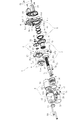
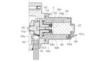
- FIG. 1 is a longitudinal sectional view showing an assembled state of an electric actuator 1 according to an embodiment of the present invention
- FIG. 2 is an external perspective view showing an assembled state of the electric actuator 1
- FIG. FIG. 1 is a longitudinal sectional view showing an assembled state of an electric actuator 1 according to an embodiment of the present invention
- FIG. 2 is an external perspective view showing an assembled state of the electric actuator 1
- FIG. FIG. 1 is a longitudinal sectional view showing an assembled state of an electric actuator 1 according to an embodiment of the present invention
- FIG. 2 is an external perspective view showing an assembled state of the electric actuator 1
- an electric actuator 1 includes a driving unit 2 that generates a driving force, a motion conversion mechanism unit 3 that converts a rotational motion from the driving unit 2 into a linear motion, and a driving unit 2.
- a driving force transmitting unit 4 for transmitting a driving force from the to the motion converting mechanism unit 3, a motion converting mechanism supporting unit 5 for supporting the motion converting mechanism unit 3, an operation unit 6 for outputting the motion of the motion converting mechanism unit 3,
- a lock device 7 for preventing the movement conversion mechanism 3 from being driven.
- the driving force transmission unit 4 corresponds to a rotational motion transmission unit according to the present invention.
- the drive section 2 includes a motor section 8 and a reduction mechanism section 9.
- each part of the electric actuator 1 has a case, and the components are accommodated in each case.
- the motor section 8 has a motor case 11 that houses a driving force generating motor (drive motor 10), and the reduction mechanism section 9 has a reduction gear case 17 that stores a reduction gear mechanism 16.
- the drive motor 10 corresponds to a first motor according to the present invention.
- the driving force transmission unit 4 has a transmission gear case 29 that houses a transmission gear mechanism 28, and the motion conversion mechanism support unit 5 has a bearing case 41 that houses a support bearing 40.
- the motor unit 8 and the speed reduction mechanism unit 9, the speed reduction mechanism unit 9 and the driving force transmission unit 4, and the driving force transmission unit 4 and the motion conversion mechanism support unit 5 are configured to be connected to and separated from each other in each case.
- the shaft case 50 is configured to be connectable and separable from the bearing case 41.
- the motor unit 8 mainly includes a driving motor (for example, a DC motor) 10 for driving the motion conversion mechanism unit 3 and a motor case 11 that houses the driving motor 10.
- the motor case 11 has a cylindrical case body 12 having a bottom and in which the driving motor 10 is housed, and a protruding portion 13 protruding from the bottom 12 a of the case body 12 to the outside.
- the protrusion 13 has a hole 13 a communicating with the internal space of the case body 12.
- the hole 13 a is sealed by a resin sealing member 14 that covers the outer surface of the protrusion 13.
- the drive motor 10 is in a state of being inserted inside from the opening 12 d of the case main body 12. At this time, the end face of the drive motor 10 on the back side in the insertion direction is in contact with the bottom 12 a of the case body 12. A fitting hole 12c is formed at the center of the bottom portion 12a, and the projection 10b on the back side in the insertion direction of the driving motor 10 is fitted into the fitting hole 12c, so that the drive protruding from the projection 10b.
- the rear end (the left end in FIG. 1) of the output shaft 10a of the motor 10 can be prevented from interfering with the bottom 12a of the motor case 11.
- the inner peripheral surface of the peripheral wall portion 12b of the case main body 12 is tapered from the opening 12d side toward the bottom portion 12a side, and is driven when the driving motor 10 is inserted into the case main body 12.
- the outer peripheral surface on the back side in the insertion direction of the motor 10 is configured to contact the inner peripheral surface of the peripheral wall portion 12b.
- the driving motor 10 is supported by the contact with the inner peripheral surface of the case main body 12 and the fitting with the fitting hole 12c in a state of being housed in the case main body 12.
- the case body 12 is provided with a pair of bus bars 15 for connecting the drive motor 10 to a power source.
- One end 15a of each bus bar 15 is connected to the motor terminal 10c by caulking, and the other end 15b is exposed to the outside from the case body 12 (see FIGS. 2 and 3).
- the other end 15b of the bus bar 15 exposed to the outside is connected to a power source.
- the reduction mechanism 9 mainly includes a reduction gear mechanism 16 that reduces and outputs the driving force of the driving motor 10 and a reduction gear case 17 that houses the reduction gear mechanism 16.
- the reduction gear mechanism 16 includes a planetary gear reduction mechanism 18 including a plurality of gears and the like. The detailed configuration of the planetary gear reduction mechanism 18 will be described later.
- the reduction gear case 17 is provided with an accommodation recess 17 a for accommodating the planetary gear reduction mechanism 18 from the side opposite to the drive motor 10.
- a motor adapter 19 is configured to be attachable to the reduction gear case 17.
- the motor adapter 19 is a cylindrical member, and the drive motor 10 is fitted to the motor adapter 19 by inserting a projection 10d on the output side (right side in FIG. 1) of the drive motor 10 into the inner peripheral surface thereof. Fit).
- the reduction gear case 17 is formed with a fitting hole 17b into which the motor adapter 19 is fitted, and the motor adapter 19 is inserted into the fitting hole 17b from the driving motor 10 side.
- a motor adapter 19 is attached.
- the reduction gear case 17 is configured to be fittable to the motor case 11 and is configured to be fittable to a transmission gear case 29 described later disposed on a side opposite to the motor case 11.
- a portion arranged on the motor case 11 side is fitted inside the opening 12 d side of the motor case 11, and a portion arranged on the transmission gear case 29 is fitted externally on the transmission gear case 29.
- the reduction gear case 17 is fastened to the drive motor 10 by bolts 21 (see FIGS. 3 and 7) together with the motor adapter 19 in a state fitted to the motor case 11.
- a mounting groove 17 d for mounting the O-ring 20 is formed on a small-diameter outer peripheral surface of the outer peripheral surface of the reduction gear case 17 that fits with the inner peripheral surface of the motor case 11.
- the motion conversion mechanism 3 is constituted by a ball screw 22 in the present embodiment.
- the ball screw 22 is composed of a ball screw nut 23 as a rotating body, a ball screw shaft 24 as a stroke part that moves linearly, a number of balls 25, and a top 26 as a circulation member.
- Helical grooves 23a and 24a are formed on the inner peripheral surface of the ball screw nut 23 and the outer peripheral surface of the ball screw shaft 24, respectively.
- the space between the spiral grooves 23a and 24a is filled with the ball 25 and the top 26 is incorporated, whereby the two rows of balls 25 circulate.
- an operation unit (actuator head) 6 for operating an operation target is provided at a forward end (left end in FIG. 1) of the ball screw shaft 24 in the forward direction.
- the ball screw nut 23 receives a driving force generated by the driving motor 10 and rotates in either the forward or reverse direction.
- the rotation of the ball screw shaft 24 around the center line X1 is restricted by a rotation restricting portion provided at the rear end (the right end in FIG. 1).
- the driving force transmission unit 4 mainly includes a transmission gear mechanism 28 that transmits driving force and rotational motion from the driving motor 10 included in the driving unit 2 to the ball screw 22 that constitutes the motion conversion mechanism unit 3, and a transmission gear mechanism 28. And a transmission gear case 29 to be accommodated.
- the transmission gear mechanism 28 has a drive gear 30 on the drive side, a driven gear 31 on the driven side that meshes with the drive gear 30, and a gear boss 32.
- the drive gear 30 corresponds to a gear whose rotation is restricted by the lock plate 60 according to the present invention.
- a gear boss 32 is fitted to the center of rotation of the drive gear 30 by press fitting or the like.
- the drive gear 30 is rotatably supported by two rolling bearings 33 and 34 mounted on the transmission gear case 29 and a bearing case 41 described later via the gear boss 32, respectively.
- the driven gear 31 is fixed by being fitted to the outer peripheral surface of the ball screw nut 23 by press fitting or the like.
- the transmission gear case 29 has a housing recess 29 a in which the drive gear 30 and the driven gear 31 are housed.
- An insertion hole 29b for inserting the gear boss 32 is formed in the transmission gear case 29, and a bearing mounting surface 29c on which one rolling bearing 33 for supporting the gear boss 32 is mounted is formed on an inner peripheral surface of the insertion hole 29b. Is formed.
- the transmission gear case 29 has an annular protrusion 29d that fits with the inner peripheral surface of the reduction gear case 17.
- a mounting groove 29e for mounting the O-ring 35 is formed on the outer peripheral surface (fitting surface) of the annular projection 29d.
- the transmission gear case 29 has a groove-like fitting concave portion 29f formed on the surface on the bearing case 41 side for fitting with the bearing case 41.
- the transmission gear case 29 has a cylindrical portion 29g that protrudes toward the tip end of the ball screw shaft 24 (left side in FIG. 1).
- the cylindrical portion 29g is a portion in which the driven gear 31 is accommodated in the transmission gear case 29, and the ball screw 22 is attached thereto so as to cover the periphery of the ball screw shaft 24.
- a boot 36 for preventing foreign matter from entering the transmission gear case 29 is attached between the cylindrical portion 29g and the ball screw shaft 24.
- the boot 36 is made of resin or rubber, and includes a large-diameter end 36a, a small-diameter end 36b, and a bellows portion 36c that extends and contracts in the axial direction by connecting the large-diameter end 36a to the small-diameter end 36b.
- the large-diameter end 36a is fastened and fixed to a mounting portion on the outer peripheral surface of the cylindrical portion 29g by a boot band 37
- the small-diameter end 36b is tightened and fixed to a mounting portion on the outer peripheral surface of the ball screw shaft 24 by a boot band 38.
- the cylindrical portion 29g is provided with a vent hole 29h for ventilating between the inside and the outside of the boot 36 when the boot 36 expands and contracts.
- the motor case 11 is integrally provided with a boot cover 39 disposed around the boot 36.
- the motion conversion mechanism support portion 5 is mainly composed of a support bearing 40 that supports the ball screw 22 that is the motion conversion mechanism portion 3, and a bearing case 41 that houses the support bearing 40.
- the support bearing 40 is formed of a back-to-back double-row angular ball bearing having an outer ring 42, an inner ring 43, and a double-row ball 44 interposed therebetween as main components.
- the support bearing 40 is accommodated in a sleeve 45 formed integrally with the bearing case 41 and is fixed by a retaining ring 46 mounted on the inner peripheral surface of the sleeve 45. Further, the fixed position of the support bearing 40 is press-fitted to the outer peripheral surface of the ball screw nut 23 on the rear end side (the right side in FIG. 1) of the ball screw shaft 24 with respect to the driven gear 31.
- the supporting bearing 40 and the driven gear 31 fixed to the outer peripheral surface of the ball screw nut 23 are axially controlled by a regulating projection 23b provided on the driven gear 31 side of the ball screw nut 23 and a regulating member 47 mounted on the supporting bearing 40 side. Movement is regulated.
- the restricting member 47 is formed of a pair of semicircular members, and is mounted on the outer peripheral surface of the ball screw nut 23 in a state where these members are combined in an annular shape. Further, a collar 48 for holding the regulating member 47 and a retaining ring 49 for preventing the collar 48 from dropping off in the axial direction are mounted on the outer peripheral surface of the ball screw nut 23.
- a ridge portion 41a that fits with the fitting recess 29f of the transmission gear case 29 is provided.
- a gear boss accommodation portion 41b is provided in which a part of the gear boss 32 protruding from the transmission gear case 29 is accommodated in a state where the bearing case 41 is fitted to the transmission gear case 29. I have.
- a bearing mounting surface 41c for mounting a rolling bearing 34 that supports the gear boss 32 is formed on the inner peripheral surface of the gear boss housing portion 41b.
- a bottomed cylindrical shaft case 50 that accommodates the rear end side (the right end side in FIG. 1) of the ball screw shaft 24 is provided with a bolt 51 (see FIG. 3). (See Reference).
- a mounting groove 50 a for mounting the O-ring 52 is formed on a surface of the shaft case 50 that contacts the bearing case 41.
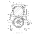
- FIG. 6 is a cross-sectional view of the cross section taken along line AA of FIG. 1 viewed from the direction of arrow A.
- FIG. 7 is an exploded perspective view of the planetary gear reduction mechanism 18.
- the planetary gear reduction mechanism 18 includes a ring gear 55, a sun gear 56, a plurality of planetary gears 57, a planetary gear carrier 58 (see FIG. 1), and a planetary gear holder 59 (see FIG. 1).
- the ring gear 55 has a plurality of convex portions 55a that protrude in the axial direction, and the accommodating concave portions 17a of the reduction gear case 17 are provided with the same number of engaging concave portions 17f as the convex portions 55a (see FIG. 1).
- the ring gear 55 is prevented from rotating relative to the reduction gear case 17 and accommodated therein by incorporating the projection 55a of the ring gear 55 into the engagement recess 17f of the reduction gear case 17 in a phase-matched state.
- a sun gear 56 is disposed at the center of the ring gear 55, and the output shaft 10a of the driving motor 10 is press-fitted into the sun gear 56.
- Each planetary gear 57 is arranged between the ring gear 55 and the sun gear 56 so as to mesh with the ring gear 55 and the sun gear 56.
- Each planet gear 57 is rotatably supported by a planet gear carrier 58 and a planet gear holder 59.
- the planetary gear carrier 58 has a cylindrical portion 58a at the center thereof, and the cylindrical portion 58a is press-fitted between the outer peripheral surface of the gear boss 32 and the inner peripheral surface of the rolling bearing 33 as described above (see FIG. 1). reference).
- An annular collar 75 is mounted between the inner peripheral surface of the other rolling bearing 34 and the outer peripheral surface of the gear boss 32.
- the sun gear 56 connected to the output shaft 10a of the driving motor 10 rotates, and accordingly, each planetary gear 57 rotates. While revolving along the ring gear 55. Then, the planetary gear carrier 58 is rotated by the revolving motion of the planetary gear 57. Thus, the rotational motion of the drive motor 10 is reduced and transmitted to the drive gear 30, and is transmitted to the drive gear 30 in a state where the rotational torque as the driving force is increased. Since the driving force is transmitted through the planetary gear reduction mechanism 18 in this manner, the driving force transmitted to the ball screw shaft 24 and the output of the ball screw shaft 24 can be greatly increased. The size of the motor 10 can be reduced.
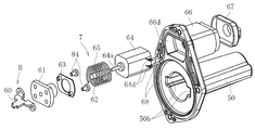
- FIG. 8 is an exploded perspective view of the shaft case 50 and the lock device 7 attached to the shaft case 50.
- FIG. 11 is a cross-sectional view taken along the line DD of FIG. It is.
- the lock device 7 includes a lock plate 60, a slide screw nut 61, a slide screw shaft 62, a fixing plate 63 for fixing the lock plate 60 to the slide screw nut 61, and a lock plate. It mainly includes a lock motor (for example, a DC motor) 64 as a drive source and a spring 65.
- a lock motor for example, a DC motor
- the sliding screw nut 61 and the sliding screw shaft 62 constitute a feed screw portion according to the present invention
- the lock motor 64 corresponds to a second motor according to the present invention
- the spring 65 corresponds to a biasing portion according to the present invention. I do.
- the sliding screw nut 61, the sliding screw shaft 62, the locking motor 64, and the spring 65 constitute an actuator section of the locking device 7 according to the present invention.
- the lock device 7 having the above configuration is assembled, for example, in the following procedure.
- the lock plate 60 is fastened to the sliding screw nut 61 with the bolt 84 (see FIG. 8) via the fixing plate 63.
- the lock motor 64 is housed in a holder 66 provided on the shaft case 50, and the slide screw shaft 62 is attached to an output shaft 64 a of the lock motor 64 protruding from the holder 66.
- a spring 65 is arranged on the outer periphery of the sliding screw shaft 62, and a sliding screw nut 61 to which the lock plate 60 is attached is screwed and mounted on the sliding screw shaft 62.
- the lock plate 60 has a plate shape as a basic shape. As shown in FIG. 9, the lock plate 60 protrudes from the base 601 in a predetermined direction and has a hole 30 a provided in an axial end face 30 b of the drive gear 30. 11 (see FIG. 11), and a pair of contact portions 603, 603 provided on both sides in the width direction of the protrusion 602 (see FIG. 9) and contacting the drive gear 30 in the axial direction. And a pair of notches 604 and 604 provided between the protruding portion 602 and the respective contact portions 603 and 603, and mounting portions 605 and 605 for mounting the lock plate 60 to the fixing plate 63.
- the protruding portion 602 protrudes in the same direction as the advancing / retreating direction Y of the lock plate 60 (see FIG. 9). It is set smaller than the dimension W2 (both refer to FIG. 12A).
- the pair of contact portions 603 each have end surfaces 603a, 603a that can contact the axial end surface 30b of the drive gear 30.
- Each end face 603a is arranged in parallel with the axial end face 30b of the drive gear 30 (see FIG. 12A), and contacts the axial end face 30b of the drive gear 30 when the lock plate 60 advances to a predetermined position.
- the position of each end face 603a is set. Specifically, the end surface 603a of each contact portion 603 is located on the rear side in the direction along the advancing / retreating direction Y of the lock plate 60 with respect to the distal end surface 602a of the protruding portion 602 (see FIG. 9).
- the drive plate 30 contacts the axial end face 30 b of the drive gear 30. (See FIG. 12B), the position of the end surface 603a along the retreating direction Y is set.
- a pair of notches 604 are respectively provided between the protruding portion 602 and each contact portion 603 as shown in FIG.
- Each notch 604 has a shape recessed toward the base 601 from the end surface 603a of each contact portion 603, is connected to the base 601 of the protruding portion 602, and the width dimension increases toward the base 601.
- a first arc portion 606 as an enlarged portion to be formed.
- each notch 604 is connected to the above-described first circular arc portion 606 and the second circular arc portion 607 which is connected to the base 601 side of the first circular arc portion 606 and whose width dimension increases toward the distal end side.
- a straight portion 608 that is connected to the distal end side of the second circular arc portion 607, extends straight toward the distal end side, and is connected to the end surface 603a of the contact portion 603.
- the radius of curvature R1 of the first circular arc portion 606 is larger than the radius of curvature R2 of the second circular arc portion 607.
- the width dimension W3 of the first arc portion 606 is larger than the width dimension W4 of the second arc portion 607 (see FIG.
- the width dimension W3 of the first circular arc portion 606 is preferably set to, for example, 15% or more and 50% or less of the width dimension W1 of the protruding portion 602.
- the first arc portion 606 and the second arc portion 607 are connected at a position where the tangent line is oriented along the width direction. Further, the first arc portion 606 is connected to the protruding portion 602 at a position where the tangent line is oriented along the retreating direction Y, and the second arc portion 607 is connected at a position where the tangent line is oriented along the retreating direction Y. It is connected to the straight part 608.
- the straight portion 608 extends in the same direction as the reciprocating direction Y of the lock plate 60, and is connected to the end surface 603a of the contact portion 603.
- the side surface 602b of the protruding portion 602 is formed in the direction along the retreating direction Y, and the side surface 30a1 of the hole 30a of the drive gear 30 (see FIG. 12A) is formed in the direction along the retreating direction Y. Have been. This allows the side surface 602b of the protrusion 602 and the side surface 30a1 of the hole 30a to come into contact with each other with the protrusion 602 inserted into the hole 30a (see FIG. 12B).
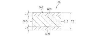
- FIG. 10 is a cross-sectional view when the protruding portion 602 of the lock plate 60 is cut along a virtual plane along the retreating direction Y.
- the protruding portion 602 is formed of two different metal structures, and in the present embodiment, the carbonitrided layer 609 formed on the surface layer and the non-carbonized region excluding the surface layer (remaining portion) are formed. And a hardened layer 610.
- the carbonitrided layer 609 and the non-hardened layer are formed of the same metal, and only the carbonitrided layer 609 has been subjected to carbonitriding.
- the total thickness T1 of the carbonitrided layer 609 (the sum of the thicknesses t1 and t2 of the carbonitrided layers 609 and 609 on both sides in FIG. 10) is 5% of the total thickness T2 of the protruding portion 602. It is adjusted to not less than 50% and preferably not less than 15% and not more than 45%.
- the carbonitrided layer 609 is preferably formed at least on the protruding portion 602 and the enlarged portion (here, the first circular arc portion 606).
- the enlarged portion (first circular arc portion 606) is not shown, but, like the protruding portion 602, is a carbonitrided layer 609 restricted to the surface layer.
- the entire thickness of the carbonitrided layer 609 is adjusted to 5% or more and 50% or less of the total thickness of the enlarged portion.
- the carbonitrided layer 609 may be formed over the entire area of the lock plate 60.
- the lock plate 60 having the above-described configuration is formed by, for example, performing a pressing process such as a punching process on a plate-shaped material having a constant thickness, and then performing a bending process.
- a carbonitriding layer 609 having a predetermined depth (predetermined thickness dimensions t1 and t2) is formed on the surface layer by performing a carbonitriding process.
- the metal of the plate material used at this time is arbitrary, but from the viewpoint of forming the carbonitrided layer 609 only on the surface layer, a metal having a poor heat treatment property (hardenability) is preferable. Such a general-purpose cold steel plate can be suitably used.
- the above example is not intended to exclude a metal having a good heat treatment property (hardenability), but employs any metal as long as the carbonitrided layer 609 can be formed so as to have the thickness dimension ratio T1 / T2 described above. It is possible to do.
- the carbonitrided layer 609 is not necessarily required, and a hardened layer hardened by another heat treatment is used for at least the projecting portion 602 and the enlarged portion of the lock plate 60. It may be formed on the surface layer.
- the holder 66 is formed in a cylindrical shape with a bottom, and a cap 67 is mounted on the opposite side of the bottom 66a.
- the locking motor 64 With the locking motor 64 inserted into the holder 66 and the cap 67 attached, the locking motor 64 contacts the bottom 66 a of the holder 66 and the inner surface of the cap 67.
- the projection 64b on the output side (the left side in FIG. 1) of the lock motor 64 is fitted into the fitting hole 66c formed in the bottom 66a of the holder 66.
- the lock motor 64 is provided in the peripheral wall portion 66b of the holder portion 66. By being inserted, the rotation of the lock motor 64 is regulated. As described above, since the lock motor 64 is accommodated in the holder 66, the lock motor 64 is held by the holder 66, and the entire lock device 7 including the lock motor 64 is held.
- the cap 67 is formed with a hole 67a for inserting a cable 68 connected to the motor terminal 64d of the lock motor 64 (see FIG. 11).
- the holder 66 is provided integrally with the shaft case 50 as a part thereof. However, it is needless to say that the holder 66 is formed separately from the shaft case 50 and attached to the bearing case 41. It doesn't matter.
- Lock device receiving recesses 66d and 41f are formed in a portion of the shaft case 50 where the holder portion 66 is provided and a portion of the bearing case 41 opposed thereto, and penetrate through the lock device receiving recess 41f on the bearing case 41 side. A hole 41g is formed.
- the output shaft 64 a of the locking motor 64 protruding from the holder 66 and the sliding screw shaft are provided in the locking device receiving recesses 66 d and 41 f.
- a sliding screw nut 61, a fixed plate 63, a spring 65, and a part of the lock plate 60 are accommodated.
- the distal end side of the lock plate 60 (here, the base 601 and the protruding portion 602; The part 603 and the notch part 604) are inserted.
- the spring 65 is axially compressed between the bottom 66 a of the holder 66 and the fixed plate 63, and the compressed spring 65 causes the lock plate 60 to move forward. 1 (the left side in FIG. 1).
- the drive gear 30 is disposed in the direction in which the lock plate 60 moves forward, and the drive gear 30 has a hole 30a into which the protrusion 602 of the lock plate 60 can be inserted.
- FIG. 13 which is a cross-sectional view taken along the line FF in FIG. 1 and viewed from the direction of arrow F, holes 30a are provided at a plurality of locations in the circumferential direction of the drive gear 30. .
- the lock plate 60 is inserted into one of these holes 30a, so that when the drive gear 30 rotates, the protrusion 602 and the hole 30a engage to restrict the rotation of the drive gear 30.
- An inclined surface 30c may be formed at the entrance of each hole 30a (see FIG. 13). By forming the hole 30a in this manner, an effect of smoothly inserting the lock plate 60 into the inside of the hole 30a by the inclined surface 30c can be expected.
- a lock sensor 69 for detecting a locked state is mounted on the bearing case 41 (see FIG. 7).
- the lock sensor 69 is a contact-type sensor having a contact 69a formed of an elastic member such as a leaf spring.
- the protrusion 602 is inserted into the hole 30a as the lock plate 60 advances, and the protrusion 602 is When the lock plate 60 is engaged with the lock member 30a (locked state), the lock plate 60 presses the contact 69a to detect the lock state.
- the lock device 7 having the above configuration performs, for example, the operation described below. That is, when power is not supplied to the lock motor 64, the lock plate 60 is held at a position advanced by the spring 65, and as shown in FIG. 12B, the distal end portion (projection portion 602) of the lock plate 60. Are engaged with the hole 30a of the drive gear 30 (locked state).
- power is supplied to the drive motor 10 to start driving the ball screw shaft 24 from this state
- power is also supplied to the lock motor 64, and the lock motor 64 moves the lock plate 60 backward. To drive. Thereby, the sliding screw shaft 62 rotates.
- the rotation of the protrusion 602 of the lock plate 60 is restricted by the through hole 41g of the slide screw nut 61 (see FIG.
- the ball screw shaft 24 is held in a state where it does not advance and retreat. Thereby, even if an external force is input from the operation target side to the ball screw shaft 24 side, the position of the ball screw shaft 24 can be held at a predetermined position.
- the above configuration is particularly suitable for the case where the electric actuator 1 is applied to an application that requires position holding.
- the lock plate 64 is moved backward by driving the lock motor 64.
- the lock motor 64 may be driven to move the lock plate 60 forward. Good.
- the lock plate 60 can be switched between forward and backward. In this case, the spring 65 becomes unnecessary.
- the electric actuator 1 is equipped with a position detection device for detecting the position of the operation unit 6 provided on the ball screw shaft 24 in the stroke direction.
- This position detecting device includes a permanent magnet 73 (see FIG. 1) as a sensor target provided on the ball screw shaft 24 and a boot cover 39 covering the boot 36, a stroke sensor for detecting the position of the permanent magnet 73 in the stroke direction.
- a magnetic sensor 70 is provided (see FIGS. 2 and 3).
- the magnetic sensor 70 is provided on the boot cover 39 formed integrally with the motor case 11. Specifically, as shown in FIG. 14, a portion of the motor case 11 where the drive motor 10 is housed (the case main body 12) and a connection portion between the boot cover 39 and the outside of the motor case 11 are provided. An open sensor case 76 is provided. A sensor base 71 on which two magnetic sensors 70 are mounted is fastened and fixed to the sensor case 76 with bolts 72 (see FIG. 3). As a result, the magnetic sensor 70 faces the ball screw shaft 24 via the boot cover 39.
- the magnetic sensor 70 is positioned radially outward of the ball screw shaft 24 so that the detection surface 70a of the magnetic sensor 70 faces the center line X1 of the ball screw shaft 24 when viewed from the direction shown in FIG. It is arranged in.
- the magnetic sensor 70 is covered with the boot cover 39, the sensor case 76, and the sensor base 71.
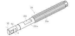
- the permanent magnet 73 is attached to the ball screw shaft 24 at a predetermined circumferential position via the magnet holder 74.
- the permanent magnet 73 faces the drive motor 10 and is perpendicular to the center line X2 (see FIG. 14) of the mating member with the connection hole 6a (circumferential position). It is arranged.
- the notch 241 for fitting and fixing the magnet holder 74 is formed in the ball screw shaft 24 (see FIG. 5), and the direction of the notch 241 (the normal to the flat surface 241a). Direction) is set to be orthogonal to the connection hole 6a.
- the permanent magnet 73 is placed in a direction shifted from the magnetic sensor 70 by 45 ° in the circumferential direction (see FIG. 14).
- any type can be used, and among them, a magnetic sensor such as a Hall IC or a linear Hall IC that can detect the direction and magnitude of a magnetic field using the Hall effect can be suitably used.
- a magnetic sensor of a type that can detect the direction and magnitude of the magnetic field even when the direction of the permanent magnet 73 is circumferentially shifted by 45 ° from the direction directly facing the magnetic sensor 70 as described above is desirable.
- the position detection device configured as described above, when the ball screw shaft 24 advances and retreats, the position of the permanent magnet 73 with respect to the magnetic sensor 70 changes, and accordingly, the magnetic field at the location where the magnetic sensor 70 is disposed also changes. Therefore, by detecting the change of the magnetic field (for example, the direction and strength of the magnetic flux density) by the magnetic sensor 70, the position of the permanent magnet 73 in the stroke direction, and thus the stroke of the operation unit 6 provided on one end side of the ball screw shaft 24. The direction position can be obtained.
- the magnetic field for example, the direction and strength of the magnetic flux density
- a control signal is sent from the controller 81 of the control device 80 to the drive motor 10.
- the target value is, for example, a stroke value calculated by the ECU based on the operation amount when the operation amount is input to the upper ECU of the vehicle.
- the drive motor 10 that has received the control signal starts to rotate, and this driving force is transmitted to the ball screw shaft 24 via the planetary gear reduction mechanism 18, the drive gear 30, the driven gear 31, and the ball screw nut 23.
- the ball screw shaft 24 advances (or retreats) in a direction parallel to the output shaft 10a of the driving motor 10.
- an operation target arranged on the tip end side (actuator head side) of the ball screw shaft 24 and connected via the connection hole 6a is operated.
- the stroke value (axial position) of the ball screw shaft 24 is detected by the magnetic sensor 70.
- the detection value detected by the magnetic sensor 70 is sent to the comparison unit 82 of the control device 80, and the difference between the detection value and the target value is calculated. Then, the driving motor 10 is driven until the detected value becomes equal to the target value.
- the electric actuator 1 of the present embodiment is applied to, for example, Can be reliably controlled.
- the electric actuator 1 has the lock device for restricting the rotation of the drive gear 30 that constitutes the transmission gear mechanism 28 that transmits the rotational motion from the drive motor 10 to the motion conversion mechanism 3.
- the lock device 7 has a lock plate 60 and an actuator unit for moving the lock plate 60 forward or backward with respect to the drive gear 30.
- the lock plate 60 has a protruding portion 602 that can be inserted into the hole 30a provided in the axial end surface 30b of the drive gear 30, and end surfaces 603a and 603a that can contact the axial end surface 30b of the drive gear 30.
- a pair of notches 604 recessed toward the base 601 from the end surface 603a of each of the contact portions 603 is provided between the pair of contact portions 603 and 603, and each of the notches 604 protrudes.
- a first arc portion 606 is provided as an enlarged portion which is connected to the base 601 side of the portion 602 and whose width dimension increases toward the base 601 side.
- the lock plate 60 By determining the shape of the lock plate 60 in this manner, when engaging with the drive gear 30 (see FIG. 12B), it is possible to avoid the situation where the notch 604 becomes the starting point of stress concentration, and to prevent the notch 604 from becoming a stress concentration.
- One circular arc portion 606 can be made large. Thereby, the strength of the protruding portion 602 against the load received from the direction of engagement with the drive gear 30 can be increased. Further, since the notch 604 is provided between the protruding portion 602 and each contact portion 603, the end face 603a of the contact portion 603 is not affected by the creation of the notch 604 at all. , Can maintain the current position.
- the strength of the lock plate 60 is improved when the rotation of the drive gear 30 is restricted, and the excessive advance of the lock plate 60 is restricted by the end face 603a (FIG. 12C). ), It is possible to prevent the lock plate 60 from biting into the drive gear 30.
- the protruding portion 602 and the enlarged portion (first arc portion 606) of the lock plate 60 are formed of a predetermined metal, and the carbonitrided layer 609 of the predetermined metal is provided on the surface layer of the protruding portion 602. Formed (see FIG. 10).
- the carbonitrided layer 609 serving as a hardened layer can be formed at a very shallow depth (several hundreds ⁇ m or less) from the surface, so that the protrusion 602 and the enlarged portion can be formed without performing post-processing.
- the ratio of the total thickness T1 of the hardened layer (carbonitrided layer 609) to the total thickness T2 of the substrate can be suppressed to 50% or less.
- the notch 604 includes a first arc portion 606 as an enlarged portion having a relatively large radius of curvature R1, a second arc portion 607 having a relatively small radius of curvature R2, and a straight portion 608.
- the cutout portion 604 can take a form other than the above.
- the enlarged portion is not limited to the arc shape, and is formed of an arbitrary curved surface portion, a tapered surface portion, a straight portion, or a combination thereof as long as the widthwise dimension W3 increases toward the base 601 side. It is also possible.
- the region of the notch portion 604 excluding the enlarged portion can be formed of an arbitrary curved surface portion, a tapered surface portion, a straight portion, or a combination thereof.
- the configuration is exemplified in which the hole 30a is provided in the axial end face 30b of the drive gear 30 constituting the transmission gear mechanism 28, and the projection 602 of the lock plate 60 can be inserted into the hole 30a.
- other configurations can of course be employed.
- a hole is provided in the axial end surface of the driven gear 31 that forms the transmission gear mechanism 28 together with the drive gear 30 as long as a space problem is allowed, and the protrusion of the lock plate 60 is formed in this hole. It is also possible to adopt a configuration in which the 602 can be inserted.
- the motion conversion mechanism 3 is not limited to the ball screw 22, but may be a sliding screw device. However, from the viewpoint of reducing the rotational torque and reducing the size of the driving motor 10, the ball screw 22 is more preferable.
- the configuration using the double-row angular ball bearing is exemplified as the support bearing 40 that supports the motion conversion mechanism unit 3. However, the configuration is not limited thereto, and a pair of single-row angular ball bearings may be used. They may be used in combination. Further, the support bearing 40 is not limited to an angular contact ball bearing, and it is also possible to apply another double row bearing using, for example, a deep groove ball bearing.
- the reduction mechanism 9 may be a reduction mechanism other than the planetary gear reduction mechanism 18. Further, by changing the gear ratio between the drive gear 30 and the driven gear 31, the driving force transmission unit 4 may also function as a reduction mechanism.
- the electric actuator 1 having both the speed reduction mechanism 9 and the lock device 7 has been exemplified, but an electric actuator having only the lock device 7 may be configured.
Landscapes
- Engineering & Computer Science (AREA)
- General Engineering & Computer Science (AREA)
- Power Engineering (AREA)
- Mechanical Engineering (AREA)
- Connection Of Motors, Electrical Generators, Mechanical Devices, And The Like (AREA)
- Braking Arrangements (AREA)
- Transmission Devices (AREA)
Abstract
L'invention concerne une plaque de verrouillage 60 permettant de limiter la rotation d'une roue 30 composant un mécanisme d'engrenage de transmission 28 servant à transmettre un mouvement de rotation d'un premier moteur 10 à un mécanisme de conversion de mouvement 4 comprenant une base 601, une saillie 602 en saillie de la base 601 et pouvant être insérée dans un trou 30a ménagé dans une surface d'extrémité dans la direction axiale 30b de la roue 30, et deux parties de contact 603 disposées des deux côtés de la saillie 602 dans la direction de la largeur et comportant chacune une surface d'extrémité 603a pouvant être amenée en contact avec la surface d'extrémité dans la direction axiale 30b de la roue 30. Deux encoches 604 plus évidées vers le côté base 601 que les surfaces d'extrémité 603a des parties de contact 603 sont disposées entre la saillie 602 et les parties de contact 603. Chaque encoche 604 comporte une partie allant en s'élargissant 606 reliée au côté base 601 de la saillie 602 et ayant une dimension dans la direction de la largeur W3 qui va en s'élargissant vers le côté base 601.
Applications Claiming Priority (2)
| Application Number | Priority Date | Filing Date | Title |
|---|---|---|---|
| JP2018-124569 | 2018-06-29 | ||
| JP2018124569A JP2020005447A (ja) | 2018-06-29 | 2018-06-29 | ロックプレートとこのプレートを備えたロック装置、並びにこのロック装置を備えた電動アクチュエータ |
Publications (1)
| Publication Number | Publication Date |
|---|---|
| WO2020004334A1 true WO2020004334A1 (fr) | 2020-01-02 |
Family
ID=68987198
Family Applications (1)
| Application Number | Title | Priority Date | Filing Date |
|---|---|---|---|
| PCT/JP2019/024970 WO2020004334A1 (fr) | 2018-06-29 | 2019-06-24 | Plaque de verrouillage, dispositif de verrouillage comprenant ladite plaque, et actionneur électrique comprenant ledit dispositif de verrouillage |
Country Status (2)
| Country | Link |
|---|---|
| JP (1) | JP2020005447A (fr) |
| WO (1) | WO2020004334A1 (fr) |
Cited By (2)
| Publication number | Priority date | Publication date | Assignee | Title |
|---|---|---|---|---|
| JPWO2021255948A1 (fr) * | 2020-06-16 | 2021-12-23 | ||
| WO2022146275A1 (fr) * | 2020-12-29 | 2022-07-07 | Sms Tork Endüstri̇yel Otomasyon Ürünleri̇ Sanayi̇ Ve Ti̇caret Li̇mi̇ted Şi̇rketi̇ | Pavé numérique à commande par stylo magnétique |
Citations (5)
| Publication number | Priority date | Publication date | Assignee | Title |
|---|---|---|---|---|
| JPH09257041A (ja) * | 1996-03-22 | 1997-09-30 | Ntn Corp | 表面起点型損傷に強い転がり軸受 |
| JP2009156416A (ja) * | 2007-12-27 | 2009-07-16 | Ntn Corp | 電動リニアアクチュエータ |
| JP2013160359A (ja) * | 2012-02-08 | 2013-08-19 | Ntn Corp | 電動式直動アクチュエータおよび電動式ブレーキ装置 |
| JP2015232368A (ja) * | 2014-06-10 | 2015-12-24 | Ntn株式会社 | 電動式直動アクチュエータおよび電動式ブレーキ装置 |
| JP2017184478A (ja) * | 2016-03-30 | 2017-10-05 | Ntn株式会社 | 電動アクチュエータ |
-
2018
- 2018-06-29 JP JP2018124569A patent/JP2020005447A/ja active Pending
-
2019
- 2019-06-24 WO PCT/JP2019/024970 patent/WO2020004334A1/fr active Application Filing
Patent Citations (5)
| Publication number | Priority date | Publication date | Assignee | Title |
|---|---|---|---|---|
| JPH09257041A (ja) * | 1996-03-22 | 1997-09-30 | Ntn Corp | 表面起点型損傷に強い転がり軸受 |
| JP2009156416A (ja) * | 2007-12-27 | 2009-07-16 | Ntn Corp | 電動リニアアクチュエータ |
| JP2013160359A (ja) * | 2012-02-08 | 2013-08-19 | Ntn Corp | 電動式直動アクチュエータおよび電動式ブレーキ装置 |
| JP2015232368A (ja) * | 2014-06-10 | 2015-12-24 | Ntn株式会社 | 電動式直動アクチュエータおよび電動式ブレーキ装置 |
| JP2017184478A (ja) * | 2016-03-30 | 2017-10-05 | Ntn株式会社 | 電動アクチュエータ |
Cited By (3)
| Publication number | Priority date | Publication date | Assignee | Title |
|---|---|---|---|---|
| JPWO2021255948A1 (fr) * | 2020-06-16 | 2021-12-23 | ||
| WO2021255948A1 (fr) * | 2020-06-16 | 2021-12-23 | 日本精工株式会社 | Dispositif de vis à billes |
| WO2022146275A1 (fr) * | 2020-12-29 | 2022-07-07 | Sms Tork Endüstri̇yel Otomasyon Ürünleri̇ Sanayi̇ Ve Ti̇caret Li̇mi̇ted Şi̇rketi̇ | Pavé numérique à commande par stylo magnétique |
Also Published As
| Publication number | Publication date |
|---|---|
| JP2020005447A (ja) | 2020-01-09 |
Similar Documents
| Publication | Publication Date | Title |
|---|---|---|
| CN109891128B (zh) | 电动致动器 | |
| CN109923767B (zh) | 电动致动器 | |
| WO2011135849A1 (fr) | Actionneur linéaire | |
| JP6679380B2 (ja) | 電動アクチュエータ | |
| US8272284B2 (en) | Electronically driven linear actuator | |
| US20100043583A1 (en) | Ball screw mechanism | |
| JP6333918B2 (ja) | 電動アクチュエータ | |
| CN109891723B (zh) | 电动致动器 | |
| WO2020004334A1 (fr) | Plaque de verrouillage, dispositif de verrouillage comprenant ladite plaque, et actionneur électrique comprenant ledit dispositif de verrouillage | |
| US11162565B2 (en) | Electric actuator | |
| CN108884920B (zh) | 具备传感器检测对象的可动部单元、以及电动致动器 | |
| JP6752649B2 (ja) | 電動アクチュエータ | |
| JP2007333046A (ja) | 電動アクチュエータ | |
| CN108779838B (zh) | 电动致动器 | |
| JP6679381B2 (ja) | 電動アクチュエータ | |
| JP6752603B2 (ja) | 電動アクチュエータ | |
| JP4731395B2 (ja) | 電動リニアアクチュエータ | |
| JP2020048392A (ja) | 電動アクチュエータ | |
| JP6700085B2 (ja) | 電動アクチュエータ | |
| JP7224145B2 (ja) | 電動アクチュエータ | |
| JP2008069793A (ja) | 電動リニアアクチュエータ | |
| JP6713315B2 (ja) | 電動アクチュエータ | |
| JP2024013560A (ja) | 送りねじ装置及びこれを備えた直動アクチュエータ | |
| JP2016161086A (ja) | 電動リニアアクチュエータ | |
| JP2017180679A (ja) | ギヤボスと伝達ギヤユニット、及びこのユニットを備えた電動アクチュエータ |
Legal Events
| Date | Code | Title | Description |
|---|---|---|---|
| 121 | Ep: the epo has been informed by wipo that ep was designated in this application |
Ref document number: 19825499 Country of ref document: EP Kind code of ref document: A1 |
|
| NENP | Non-entry into the national phase |
Ref country code: DE |
|
| 122 | Ep: pct application non-entry in european phase |
Ref document number: 19825499 Country of ref document: EP Kind code of ref document: A1 |