WO2020004222A1 - 検査マスタ - Google Patents
検査マスタ Download PDFInfo
- Publication number
- WO2020004222A1 WO2020004222A1 PCT/JP2019/024503 JP2019024503W WO2020004222A1 WO 2020004222 A1 WO2020004222 A1 WO 2020004222A1 JP 2019024503 W JP2019024503 W JP 2019024503W WO 2020004222 A1 WO2020004222 A1 WO 2020004222A1
- Authority
- WO
- WIPO (PCT)
- Prior art keywords
- master
- inspection
- oblique
- peripheral surface
- peripheral
- Prior art date
Links
Images


Classifications
-
- B—PERFORMING OPERATIONS; TRANSPORTING
- B23—MACHINE TOOLS; METAL-WORKING NOT OTHERWISE PROVIDED FOR
- B23Q—DETAILS, COMPONENTS, OR ACCESSORIES FOR MACHINE TOOLS, e.g. ARRANGEMENTS FOR COPYING OR CONTROLLING; MACHINE TOOLS IN GENERAL CHARACTERISED BY THE CONSTRUCTION OF PARTICULAR DETAILS OR COMPONENTS; COMBINATIONS OR ASSOCIATIONS OF METAL-WORKING MACHINES, NOT DIRECTED TO A PARTICULAR RESULT
- B23Q17/00—Arrangements for observing, indicating or measuring on machine tools
- B23Q17/22—Arrangements for observing, indicating or measuring on machine tools for indicating or measuring existing or desired position of tool or work
- B23Q17/2233—Arrangements for observing, indicating or measuring on machine tools for indicating or measuring existing or desired position of tool or work for adjusting the tool relative to the workpiece
-
- G—PHYSICS
- G01—MEASURING; TESTING
- G01B—MEASURING LENGTH, THICKNESS OR SIMILAR LINEAR DIMENSIONS; MEASURING ANGLES; MEASURING AREAS; MEASURING IRREGULARITIES OF SURFACES OR CONTOURS
- G01B7/00—Measuring arrangements characterised by the use of electric or magnetic techniques
- G01B7/004—Measuring arrangements characterised by the use of electric or magnetic techniques for measuring coordinates of points
- G01B7/008—Measuring arrangements characterised by the use of electric or magnetic techniques for measuring coordinates of points using coordinate measuring machines
-
- G—PHYSICS
- G01—MEASURING; TESTING
- G01B—MEASURING LENGTH, THICKNESS OR SIMILAR LINEAR DIMENSIONS; MEASURING ANGLES; MEASURING AREAS; MEASURING IRREGULARITIES OF SURFACES OR CONTOURS
- G01B21/00—Measuring arrangements or details thereof, where the measuring technique is not covered by the other groups of this subclass, unspecified or not relevant
- G01B21/02—Measuring arrangements or details thereof, where the measuring technique is not covered by the other groups of this subclass, unspecified or not relevant for measuring length, width, or thickness
- G01B21/04—Measuring arrangements or details thereof, where the measuring technique is not covered by the other groups of this subclass, unspecified or not relevant for measuring length, width, or thickness by measuring coordinates of points
- G01B21/042—Calibration or calibration artifacts
-
- G—PHYSICS
- G01—MEASURING; TESTING
- G01B—MEASURING LENGTH, THICKNESS OR SIMILAR LINEAR DIMENSIONS; MEASURING ANGLES; MEASURING AREAS; MEASURING IRREGULARITIES OF SURFACES OR CONTOURS
- G01B21/00—Measuring arrangements or details thereof, where the measuring technique is not covered by the other groups of this subclass, unspecified or not relevant
- G01B21/02—Measuring arrangements or details thereof, where the measuring technique is not covered by the other groups of this subclass, unspecified or not relevant for measuring length, width, or thickness
- G01B21/04—Measuring arrangements or details thereof, where the measuring technique is not covered by the other groups of this subclass, unspecified or not relevant for measuring length, width, or thickness by measuring coordinates of points
- G01B21/047—Accessories, e.g. for positioning, for tool-setting, for measuring probes
-
- G—PHYSICS
- G01—MEASURING; TESTING
- G01B—MEASURING LENGTH, THICKNESS OR SIMILAR LINEAR DIMENSIONS; MEASURING ANGLES; MEASURING AREAS; MEASURING IRREGULARITIES OF SURFACES OR CONTOURS
- G01B5/00—Measuring arrangements characterised by the use of mechanical techniques
- G01B5/004—Measuring arrangements characterised by the use of mechanical techniques for measuring coordinates of points
- G01B5/008—Measuring arrangements characterised by the use of mechanical techniques for measuring coordinates of points using coordinate measuring machines
Definitions
- the present invention relates to an inspection master capable of performing an accuracy inspection of a contact type three-dimensional measuring machine and an accuracy inspection (measurement) of a five-axis machine.
- ⁇ 3Three-axis processing machines and five-axis processing machines are used for processing mechanical parts such as automobile engines and transmission cases.
- One example of a five-axis machine is a five-axis machining center.
- the five axes are usually a total of five axes in which two axes, a rotation axis and a rotation axis, are added to three axes of left and right (X axis), front and rear (Y axis), and up and down (Z axis).
- a contact type three-dimensional measuring machine is used for measuring the dimensions of the machine parts processed by three-axis machining.
- the contact type three-dimensional measuring machine is provided with a spherical probe (contact), and the probe is brought into contact with an object to be measured set on a measurement table to measure the size and smoothness of the object to be measured. Is what you do.
- Patent Documents 1 and 2 In order to maintain the measurement accuracy, the contact type three-dimensional measuring machine periodically performs an inspection of the measurement accuracy using a highly accurate inspection master.
- the present applicant has also developed and proposed an inspection master first (Patent Documents 1 and 2).
- the inspection master A developed earlier by the applicant of the present application has four upper surface measuring parts D1 serving as measurement standards on the upper surface C of a hollow cylindrical master body B, and measures the peripheral surface E.
- a reference hole (vertical hole) F that opens vertically is provided at the center of the upper surface measurement unit D1
- a reference hole (lateral hole) G that opens horizontally is provided at the center of the peripheral surface measurement unit D2.
- a portal type One of the contact type three-dimensional measuring machines is called a portal type.
- a gate-shaped movable frame H that can slide back and forth in the Y direction (front-rear direction) and a head portion I that is supported by the gate-shaped movable frame H and that can slide back and forth in the X direction (right and left direction).
- a probe K at the end thereof which is supported so as to be able to move up and down in the Z direction (vertical direction) with respect to the head unit I.
- the tip of the probe K is made of a hard and wear-resistant material such as artificial ruby or ceramics, and is formed in a highly accurate spherical shape.
- the inspection master A of FIG. 18 is used to inspect the measurement accuracy of the portal-type contact type three-dimensional measuring machine of FIG.
- the inspection master A is set on the holder M attached to the measurement table L of the contact type three-dimensional measuring machine.
- the probe K of the contact type three-dimensional measuring machine is brought into contact with the inner peripheral surface and the measurement reference surface N of the upper surface measuring unit D1 and the peripheral surface measuring unit D2 of the inspection master A, and the smoothness of the contact point and the contact type 3 are measured. Measure various items required for evaluation of the dimension measuring machine.
- the measured value (actually measured value) is compared with a reference value that has been confirmed for weighing traceability to check an error between the actually measured value and the reference value, or to determine the straightness of each axis along which the probe K moves and the distance between axes. Inspection of the contact-type three-dimensional measuring machine itself is performed by examining a squareness, an error in each axial direction, and the like.
- the vertical hole F of the upper surface measuring portion D1 of the inspection master A of FIG. 18 is opened vertically to the upper surface C, and the horizontal hole G of the peripheral surface measuring portion D2 of the peripheral surface E is opened horizontally to the peripheral surface E. Therefore, it is possible to measure by inserting the probe K into the vertical hole F and the horizontal hole G, or to measure the smoothness by bringing the probe K of the contact type three-dimensional measuring machine into contact with the measurement reference plane N, The measurement in the oblique direction with respect to the axial direction of the master body B could not be performed.
- a five-axis machine having three axes of X, Y, and Z and two axes of rotation or rotation has been widely used, but an inspection master suitable for performing an accuracy inspection of the five-axis machine is also available. not exist.
- the present invention is to provide an inspection master capable of performing an accuracy inspection and inspection of a five-axis machine and an accuracy inspection and inspection of a contact type three-dimensional measuring machine.
- One of the inspection masters of the present invention has an upper surface oblique reference portion on the upper surface of a three-dimensional master body.
- the upper oblique reference portion has an obliquely upward reference hole.
- Another one of the inspection masters according to the present invention is provided with a peripheral oblique reference portion on the peripheral surface of the master body.
- the peripheral oblique reference portion is formed by opening a reference hole obliquely upward.
- both the upper surface oblique reference portion and the peripheral surface oblique reference portion can be provided on the master body. It is desirable that each of the inspection masters has a reference sphere on the upper surface of the master body.
- the inspection master may have the upper surface vertical reference portion on the upper surface or the peripheral surface horizontal reference portion on the peripheral surface. Further, it may be provided with both the upper surface vertical reference portion and the peripheral surface horizontal reference portion.
- the upper surface vertical reference portion has a vertical hole opened, and the peripheral surface horizontal reference portion has a horizontal hole opened.
- the inspection master of the present invention has the following effects. (1) When the upper surface oblique reference portion is provided on the master main body, the contact attached to the 5-axis machine is brought into contact with the upper surface oblique reference portion of the rotated or / and rotated inspection master to rotate or rotate the axis. Can be measured, so that a total of five axes can be measured in addition to the conventional three-axis measurement of the X-axis, the Y-axis, and the Z-axis, and the accuracy of a five-axis machine can be inspected.
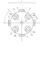
- FIG. 1A is a perspective view of a first example of the inspection master of the present invention
- FIG. 1B is an explanatory view of a portion O of FIG. 1A, and shows a state before a flanged bush is inserted into a peripheral surface mounting hole of the master body.
- FIG. 3 is an explanatory view of an O portion of FIG. 3A in which a flanged bush is inserted and fixed in a peripheral surface mounting hole of a master body.
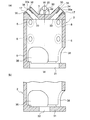
- 1A is a cross-sectional view taken along line dd of FIG.
- FIG. 4 is a perspective view of a second example of the inspection master according to the present invention.
- the top view of FIG. FIG. 6 is a sectional view taken along line cc of FIG. 5.
- FIG. 6 is a sectional view taken along line dd of FIG. 5.
- FIG. 9 is a perspective view of a third example of the inspection master of the present invention.
- the top view of FIG. FIG. 10 is a sectional view taken along line cc of FIG. 9.
- FIG. 10 is a sectional view taken along line dd of FIG. 9.
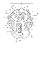
- FIG. 14 is a perspective view of a fourth example of the inspection master of the present invention.
- FIG. 14 is a plan view of FIG. 13.
- FIG. 14 is a sectional view taken along line cc of FIG. 13.
- FIG. 14 is a sectional view taken along line dd of FIG. 13.
- (A) is a perspective explanatory view of a method of measuring the center coordinates of a reference sphere
- (b) is a side explanatory view of the measuring method
- (c) is a plan explanatory view of the measuring method.
- FIG. 2 is a perspective view of an inspection master previously developed by the present applicant.
- FIG. 19 is an explanatory diagram in the case of performing measurement by a portal-type contact three-dimensional measuring machine using the inspection master of FIG. 18.
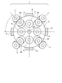
- the inspection master 1 has four oblique reference portions 30 and one reference sphere 20 on an upper surface 3 of a hollow cylindrical master main body 2, and a peripheral surface 5 has four rows of peripheral surface reference portions 6.
- the number of upper surface oblique reference portions 30 can be one or more arbitrary numbers.
- the upper surface oblique reference portion 30 is obliquely upward and has an obliquely upward upper opening 30a.
- the four rows of circumferential surface reference portions 6 are provided at 90-degree intervals in the circumferential direction of the circumferential surface 5 of the master main body 2, but the intervals may be other values.
- the peripheral surface lateral reference portion 6 has a lateral opening hole 6a.
- the number of the peripheral lateral reference portions 6 may be one or more, and the number of the peripheral lateral reference portions 6 in each row may be one or more.
- the reference sphere 20 is attached by a shaft 22 and is separated from the upper surface 3. By separating from the upper surface 3, as shown in FIG. 17, the spherical measurement probe 21 is easily brought into contact.
- the size of the reference sphere 20 is designed to be a size suitable for measurement.
- the inspection master 1 shown in FIGS. 5 to 8 has four upper oblique reference portions 30 with oblique openings at four locations on the upper surface 3 of the hollow cylindrical master body 2, a reference sphere 20 at the center of the upper surface 3, and an upper surface 3.
- the number of the upper surface oblique reference portion 30 and the number of the upper surface vertical reference portion 4 are one or more arbitrary numbers
- the number of the peripheral surface horizontal reference portions 6 is one or more arbitrary numbers
- the number of the peripheral surface horizontal reference portions 6 is one or more arbitrary number. It can be.
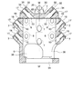
- the inspection master 1 shown in FIGS. 9 to 12 has four upper oblique reference portions 30 on the upper surface 3 of the hollow cylindrical master body 2, a reference sphere 20 at the center of the upper surface 3, and the peripheral surface of the master body 2.
- the inspection master 1 shown in FIGS. 13 to 16 has four upper oblique reference portions 30 on the upper surface 3 of the hollow cylindrical master body 2, a reference sphere 20 at the center of the upper surface 3, and the upper oblique reference portion 30.
- peripheral lateral reference portions 6 having lateral openings in the circumferential direction of the peripheral surface 5 of the master body 2
- a peripheral oblique reference portion 7 of an obliquely upper opening is provided between the four rows of peripheral lateral reference portions 6.
- each of the peripheral surface lateral reference portions 6 and the peripheral surface oblique reference portions 7 of each row is two, the number of rows and the number of each row may be other numbers.
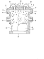
- the master main body 2 of the embodiment has an upper surface 3 and a peripheral surface 5 as shown in FIG. 1, an open bottom surface 31 as shown in FIGS. Shape).
- the bottom surface 31 may be closed as shown in FIG. 4B, and a stopper hole 32 may be opened at the center.
- an opening 36 is opened in the lower outer peripheral surface of the master main body 2.
- the master body 2 can be reduced in weight, and can be used to set and fix the inspection master 1 on the measurement table.
- three openings 36 are shown in the figure, the number may be any number.
- the size of the opening 36 is also arbitrary. For example, a width of about 65 mm and a height of about 30 mm are suitable.
- the master body 2 is preferably made of a material having small thermal expansion and excellent dimensional stability.
- a material having small thermal expansion and excellent dimensional stability For example, ceramics, quartz, crystal, low thermal expansion cast iron, SK steel, and other materials are suitable. It can be made by cutting out a single block (block) of these materials, or can be made by laminating plates made of these materials.
- the master body 2 of any of the embodiments has basically the same shape, structure, and size, but may be changed in design as needed.
- the master main body 2 may be a square hollow cylinder. In this case, a portion corresponding to the peripheral surface 5 is a flat side surface.
- an upper surface oblique mounting hole 33 (FIG. 4A) is opened in the upper surface 3 and a peripheral surface mounting hole 9 (FIG. 3A) is opened in the peripheral surface 5. ing.
- the upper surface 3 of the master main body 2 shown in FIGS. 5 to 8 has an upper surface oblique mounting hole 33 (FIG. 8) and an upper surface mounting hole 8 (FIG. 7), and the peripheral surface 5 has a peripheral surface mounting hole 9 (FIG. 7). Is open.
- an upper surface oblique mounting hole 33 (FIG. 12) is opened on the upper surface 3, and a peripheral surface mounting hole 9 (FIG. 11) and a peripheral surface oblique mounting hole 10 (FIG. 12) is open.
- the upper surface 3 has an upper surface oblique mounting hole 33 (FIG. 16) and an upper surface mounting hole 8 (FIG. 15), and the peripheral surface 5 has a peripheral surface mounting hole 9 (FIG. 15).
- a peripheral oblique mounting hole 10 (FIG. 16) is opened.
- the upper surface oblique reference portion 30 (FIG. 1) is the same in any of the embodiments, and the flanged bush 17 (FIG. 3B) is provided in the upper surface oblique mounting hole 33 (FIG. 4A) of the master main body 2. Inserted and fixed. As shown in FIG. 3B, the flanged bush 17 has a flange 17b at the tip of a cylindrical insertion portion 17a.
- the through hole 17c (FIG. 3B) of the insertion portion 17a is an oblique reference hole 34 (FIG. 4A), and the surface of the flange 17b (FIG. 3B) is an oblique measurement reference surface 35 (FIG. 4A). )).
- the oblique reference hole 34 is open in a direction (obliquely upward) crossing the center axis WW (FIG. 4A) of the master main body 2 at an angle of 45 degrees. Both the inner peripheral surface of the oblique reference hole 34 and the surface of the oblique measurement reference surface 35 are finished smoothly.
- the intersection angle between the oblique reference hole 34 and the center axis WW (FIG. 4A) of the master main body 2 can be set to an arbitrary angle, for example, 30 degrees or 60 degrees.
- the four rows of the peripheral surface 5 of the master main body 2 and the two lateral lateral reference portions 6 (FIGS. 1 and 3A) of each row have the same shape, and a flange is provided in the peripheral surface mounting hole 9 of the master main body 2.
- the bush 17 (FIG. 3B) is inserted and fixed, the through hole 17c (FIG. 3B) of the flanged bush 17 is used as the horizontal reference hole 15, and the flange 17b of the flanged bush 17 (FIG. 3B). )) Is used as the horizontal measurement reference plane 16.
- the horizontal reference hole 15 is open in a direction (direct lateral direction) orthogonal to the central axis WW of the master main body 2 (FIG. 4A).
- the circumferential lateral reference portions 6 in each row are provided in four rows, and two rows are provided at intervals (FIGS. 1A and 2). The number and the interval between each row can be arbitrarily designed.
- the four upper surface vertical reference portions 4 (FIG. 5) of the master main body 2 are arranged and fixed inside the upper surface oblique reference portion 30 and outside the reference sphere 20.
- the upper surface vertical reference portion 4 is fixed by inserting a flanged bush 17 (FIG. 3 (b)) into an upper surface mounting hole 8 (FIG. 7) of the master main body 2, and a through hole 17c (FIG. b)) is the vertical reference hole 12, and the surface of the flange 17 b (FIG. 3B) of the flanged bush 17 is the upper measurement reference surface 13.
- the vertical reference hole 12 is opened in parallel with the central axis WW of the master main body 2 (FIG. 7). Both the inner peripheral surface of the vertical reference hole 12 and the surface of the upper measurement reference surface 13 are finished smoothly.
- the number and interval of the upper surface vertical reference portions 4 can be arbitrarily designed.
- the peripheral diagonal reference portions 7 in each row are provided in four rows and two in each row (FIGS. 9 and 10), but the number of rows, the number of each row, and the interval between the rows can be arbitrarily designed. it can.
- the intersection angle between the oblique reference hole 18 and the central axis WW (FIG. 12) of the master main body 2 can be set to an arbitrary angle, for example, 30 degrees or 60 degrees.
- the flanged bush 17 As the flanged bush 17 (FIG. 3B), an existing (commercially available) flanged bush or a new flanged bush can be used.
- the flanged bush 17 is preferably formed of a material such as low-thermal-expansion cast iron having a small coefficient of thermal expansion, and the surface of the flange 17b and the inner peripheral surface of the through hole 17c are preferably mirror-finished with high precision. The finishing can be performed before or after the individual flanged bushes 17 are fixed to the master main body 2. However, when the finishing is performed, the accuracy of the mounting angle and the mounting position to the master main body 2 can be improved. it can.
- the fixing of the flanged bush 17 to each of the mounting holes can be performed by any means, but can be performed by Loctite or another adhesive. If necessary, caulking, screws, or other fixing means may be used.
- the master main body 2 and the flanged bush 17 are separately formed, and the flanged bush 17 is formed on the upper surface mounting hole 8, the peripheral surface mounting hole 9, the peripheral surface oblique mounting hole 10, the upper surface oblique mounting hole of the master main body 2.
- the master body 2 and the flanged bush 17 may be integrated if possible.
- the reference sphere 20 at the center of the upper surface 3 of the master main body 2 is attached so as to protrude upward from the upper surface 3 of the master main body 2 (separated from the upper surface) by a shaft 22 as shown in FIG. By attaching in this manner, the spherical measuring probe 21 for measurement (FIG. 17) can be easily contacted.
- the inspection master 1 is set on a holder of a measurement table (not shown) as described later. By rotating or turning the holder, the holder is inclined as shown in FIG.
- the reference sphere 20 serves as a reference for confirming the inclination angle of the inspection master 1 at that time.
- the inspection master 1 of the present invention is set on the holder and the contact type three-dimensional measurement is performed similarly to the conventional three-dimensional measurement.
- the inspection is performed by moving the probe of the machine in three axial directions of X, Y, and Z so as to contact the upper surface vertical reference portion 4 and the peripheral surface horizontal reference portion 6 of the inspection master.
- the measurement head and the spherical measurement probe 21 ( FIG. 17 (a) is set, and the inspection master 1 of the present invention is set on a holder that can rotate or rotate, or rotate and rotate.
- the measurement probe 21 is moved in three directions of X, Y, and Z to perform three-dimensional measurement.
- the holder is rotated or rotated, or rotated and rotated, and the inspection master 1 set on the holder is inclined with respect to the measurement probe 21 (FIG. 17A).
- the inner peripheral surface of the oblique reference hole 18 (34) or the oblique measurement reference surface 19 (35) of the peripheral oblique reference portion 7 and the upper oblique reference portion 30 of the inspection master 1 of the present invention are brought into contact with each other to measure necessary items such as the smoothness and the inclination angle of the contact points (together with the three-axis measurement, a total of five axes). These measured values (measured values) are compared with reference values for which traceability has been confirmed to check the error between the measured values and the reference values, or the straightness and the distance between the axes in which the measuring probe 21 moves are measured. , The display error in each axial direction, the distance between the holes, and the like can be confirmed, and the measurement device itself can be evaluated. If there is an error, the measuring machine and the processing machine can be adjusted so that the error is eliminated.
- the inspection master 1 is tilted, so it is necessary to check the tilt angle. In this case, it can be confirmed using the reference sphere 20.
- the outer peripheral surface (top) of the spherical measurement probe 21 is placed on the four front, rear, left, and right sides of the outer peripheral surface of the reference sphere 20 and upward.
- the coordinates of the center of the reference sphere 20 are obtained by making contact with a total of five points on the top. This coordinate value is compared with the reference coordinate value, and the inclination of the inspection master 1 is obtained from the difference between the two coordinates.
- the reference coordinate value may be the center coordinate of the reference sphere 20 when the upper surface of the inspection master 1 set on the holder is horizontal.
- the outer peripheral surface (top) of the spherical measuring probe 21 is divided into four apexes at the front, rear, left and right of the outer peripheral surface of the reference sphere 20, and a total of five upper apexes.
- the inclination angle of the peripheral oblique reference portion 7 is, for example, 45 degrees, it is checked whether the inspection master is accurately inclined at 45 degrees, and the holder is rotated or turned to accurately rotate the inspection master 1 at 45 degrees. Angle can be adjusted.
- the spherical measurement probe 21 is brought into contact with the oblique reference hole 18 or the oblique measurement reference surface 19 of the peripheral oblique reference portion 7, By measuring the smoothness, the inter-axis angle, and the like of those measurement points, accurate five-axis measurement can be performed. Accurate five-axis measurement is also possible by contacting the oblique reference hole 34 or the oblique measurement reference surface 35 of the upper oblique reference portion 30 and measuring the smoothness, inter-axis angle, and the like of those measurement locations.
- the method of obtaining the inclination angle may be another method.
- the measurement probe 21 may be an articulated arm type probe or a probe having another configuration.
- the inspection master 1 of the present invention is not limited to the above embodiment, and may have other configurations, dimensions, materials, and the like as long as the problems of the present invention can be solved.
- the number and locations of the upper surface vertical reference portion 4, upper surface oblique reference portion 30, peripheral surface horizontal reference portion 6, and peripheral surface oblique reference portion 7 can be arbitrarily designed.
- the upper surface oblique reference portion 30 may have an inward inclination facing the center side of the master main body 2 instead of the outward inclination facing the outer peripheral direction of the master main body 2.
- the master body 2 is not limited to a cylindrical shape, but may be a square, a polygonal box, or another shape.
Landscapes
- Physics & Mathematics (AREA)
- General Physics & Mathematics (AREA)
- Engineering & Computer Science (AREA)
- Mechanical Engineering (AREA)
- A Measuring Device Byusing Mechanical Method (AREA)
Abstract
本発明の検査マスタの一つは、上面と周面があるマスタ本体の上面に、斜め上向き開口の上面斜め基準部を設けた。本発明の検査マスタの他の一つは、上面と周面があるマスタ本体の周面に斜め上向き開口の周面斜め基準部を設けた。前記いずれの場合も、上面に縦向き開口の上面縦基準部を設けることも、周面に横向き開口の周面横基準部を設けることもできる。また、上面中心部に5軸加工機の精度検査時に傾斜させるマスタ本体の傾斜角を求める基準球を設けた。
Description
本発明は、接触式3次元測定機の精度検査を行うことも、5軸加工機の精度検査(測定)を行うこともできる検査マスタに関する。
自動車用エンジン、変速機のケースといった機械部品類の加工には、3軸加工機や5軸加工機が使用されている。5軸加工機の一例は5軸マシニングセンターである。5軸は通常、左右(X軸)、前後(Y軸)、上下(Z軸)の3軸に、回転軸と旋回軸の2軸を付加した計5軸である。
3軸加工された機械部品類の寸法測定には、接触式3次元測定機が用いられている。接触式3次元測定機は球状のプローブ(接触子)を備えており、そのプローブを、測定テーブルの上にセットした被測定物に接触させて、被測定物の寸法や平滑度等の測定を行うものである。
接触式3次元測定機は、測定精度を維持するために、高精度に仕上げられた検査マスタを用いて、定期的に測定精度の検査を行っている。本件出願人も先に検査マスタを開発し提案をしている(特許文献1、2)。
本件出願人が先に開発した検査マスタAは、図18のように、中空筒状のマスタ本体Bの上面Cに、測定基準となる上面測定部D1が4個設けられ、周面Eに測定基準となる周面測定部D2が4列、各列2個ずつ設けられている。上面測定部D1の中心には縦向きに開口する基準孔(縦孔)Fがあり、周面測定部D2の中心には横向きに開口する基準孔(横孔)Gがある。
接触式3次元測定機の一つに門型と呼ばれるものがある。それは、図19のように、Y方向(前後方向)に往復スライド自在な門型可動フレームHと、門型可動フレームHに支持されてX方向(左右方向)に往復スライド自在なヘッド部Iと、ヘッド部Iに対してZ方向(上下方向)に昇降自在に支持された昇降軸Jと、その先のプローブKを有する。プローブKの先端部は人造ルビーやセラミックス等の硬質で耐摩耗性のある素材で高精度の球状に形成されている。
図18の検査マスタAを用いて、図19の門型の接触式3次元測定機の測定精度の検査や、測定誤差の校正に必要なデータ取りを行うときは、図19のように、門型の接触式3次元測定機の測定テーブルLに取り付けられたホルダーMに検査マスタAをセットする。その検査マスタAの上面測定部D1、周面測定部D2の内周面や測定基準面Nに、接触式3次元測定機のプローブKを接触させて、接触箇所の平滑度や、接触式3次元測定機の評価に必要な各種事項について測定する。その測定値(実測値)を計量トレサビリティーの確認されている基準値と比較することにより実測値と基準値との誤差を調べたり、プローブKが移動する各軸方向の真直度、軸間の直角度、各軸方向の誤差等を調べたりして、接触式3次元測定機自体の検査が行われている。
図18の検査マスタAの上面測定部D1の縦孔Fは上面Cに垂直に開口しており、周面Eの周面測定部D2の横孔Gは周面Eに水平に開口しているため、それら縦孔F、横孔GにプローブKを差し込んで測定したり、測定基準面Nに接触式3次元測定機のプローブKを接触させて平滑度を測定したりすることはできるが、マスタ本体Bの軸方向に対する斜め方向の測定はできなかった。また、近年は、X、Y、Zの3軸に回転又は旋回の2軸を付加した5軸加工機が汎用されているが、5軸加工機の精度検査を行うのに適した検査マスタも存在しない。
本発明は5軸加工機の精度検査や点検を行うことも、接触式3次元測定機の精度検査や点検を行うこともできる検査マスタを提供することにある。
本発明の検査マスタの一つは、立体形状のマスタ本体の上面に上面斜め基準部を備えたものである。上面斜め基準部は斜め上向きの基準孔が開口されている。本発明の検査マスタの他の一つはマスタ本体の周面に周面斜め基準部を備えたものである。周面斜め基準部は斜め上向きの基準孔が開口されたものである。本発明の検査マスタの他の一つはマスタ本体に前記上面斜め基準部と前記周面斜め基準部の双方を設けることもできる。前記いずれの検査マスタもマスタ本体の上面に基準球を備えたものが望ましい。
本発明の検査マスタのいずれの場合も、上面に上面縦基準部を備えたものでも、周面に周面横基準部を備えたものであってもよい。更には、前記上面縦基準部と前記周面横基準部の双方を備えたものであってもよい。上面縦基準部は縦向き孔が開口されたものであり、周面横基準部は横向き孔が開口されたものである。
本発明の検査マスタは次の効果がある。
(1)マスタ本体に上面斜め基準部を設けた場合は、回転又は/及び旋回させた検査マスタの上面斜め基準部に、5軸加工機に取り付けた接触子を接触させて回転軸又は旋回軸の軸測定ができるので、これまでのX軸、Y軸、Z軸の3軸測定と合わせて計5軸測定が可能になり、5軸加工機の精度検査もできる。
(2)マスタ本体に周面斜め基準部を設けた場合は、回転又は/及び旋回させた検査マスタの周面斜め基準部に、5軸加工機に取り付けた接触子を接触させて回転軸又は旋回軸の軸測定ができるので、これまでのX軸、Y軸、Z軸の3軸測定と合わせて計5軸測定が可能になり、5軸加工機の精度検査もできる。
(3)検査マスタを回転又は/及び旋回させても、マスタ本体の上面の基準球を基準として検査マスタの回転傾斜角又は旋回傾斜角を確認できるため高精度の5軸測定ができる。
(検査マスタの実施形態1)
図1~図4は本発明の検査マスタ1の一例である。この検査マスタ1は中空筒状のマスタ本体2の上面3に4個の上面斜め基準部30と1個の基準球20があり、周面5に4列の周面横基準部6がある。上面斜め基準部30の数は一以上の任意数とすることができる。上面斜め基準部30は斜め上向きであり、斜め上向きの上開口孔30aがある。4列の周面横基準部6はマスタ本体2の周面5の周方向に90度間隔で設けてあるが、その間隔はそれ以外であってもよい。周面横基準部6は横向きの横開口孔6aを備えている。周面横基準部6は一列以上の任意数、各列の周面横基準部6は一以上の任意数とすることができる。基準球20は軸22で取り付けられて上面3から離れている。上面3から離れることにより、図17のように、球状の測定プローブ21を接触させ易くなる。基準球20のサイズは計測に適するサイズに設計されている。
図1~図4は本発明の検査マスタ1の一例である。この検査マスタ1は中空筒状のマスタ本体2の上面3に4個の上面斜め基準部30と1個の基準球20があり、周面5に4列の周面横基準部6がある。上面斜め基準部30の数は一以上の任意数とすることができる。上面斜め基準部30は斜め上向きであり、斜め上向きの上開口孔30aがある。4列の周面横基準部6はマスタ本体2の周面5の周方向に90度間隔で設けてあるが、その間隔はそれ以外であってもよい。周面横基準部6は横向きの横開口孔6aを備えている。周面横基準部6は一列以上の任意数、各列の周面横基準部6は一以上の任意数とすることができる。基準球20は軸22で取り付けられて上面3から離れている。上面3から離れることにより、図17のように、球状の測定プローブ21を接触させ易くなる。基準球20のサイズは計測に適するサイズに設計されている。
(検査マスタの実施形態2)
図5~図8の検査マスタ1は中空筒状のマスタ本体2の上面3の4箇所に斜め開口の上面斜め基準部30が4個あり、上面3の中心部に基準球20があり、上面斜め基準部30の内側であって基準球20の外周に縦開口の上面縦基準部4が4個あり、マスタ本体2の周面5の周方向4箇所に横向き開口の周面横基準部6が4列ある。上面斜め基準部30、上面縦基準部4の数は一以上の任意数、周面横基準部6は一列以上の任意数、各列の周面横基準部6の数は一以上の任意数とすることができる。
図5~図8の検査マスタ1は中空筒状のマスタ本体2の上面3の4箇所に斜め開口の上面斜め基準部30が4個あり、上面3の中心部に基準球20があり、上面斜め基準部30の内側であって基準球20の外周に縦開口の上面縦基準部4が4個あり、マスタ本体2の周面5の周方向4箇所に横向き開口の周面横基準部6が4列ある。上面斜め基準部30、上面縦基準部4の数は一以上の任意数、周面横基準部6は一列以上の任意数、各列の周面横基準部6の数は一以上の任意数とすることができる。
(検査マスタの実施形態3)
図9~図12の検査マスタ1は中空筒状のマスタ本体2の上面3に4個の上面斜め基準部30があり、上面3の中心部に基準球20があり、マスタ本体2の周面5の周方向に横向き開口の周面横基準部6が4列あり、4列の周面横基準部6の間に斜め上方開口の周面斜め基準部7が4列ある。各列の周面横基準部6も周面斜め基準部7も2個ずつあるが、前記列数、各列の個数は前記以外の数であってもよい。
図9~図12の検査マスタ1は中空筒状のマスタ本体2の上面3に4個の上面斜め基準部30があり、上面3の中心部に基準球20があり、マスタ本体2の周面5の周方向に横向き開口の周面横基準部6が4列あり、4列の周面横基準部6の間に斜め上方開口の周面斜め基準部7が4列ある。各列の周面横基準部6も周面斜め基準部7も2個ずつあるが、前記列数、各列の個数は前記以外の数であってもよい。
(検査マスタの実施形態4)
図13~図16の検査マスタ1は中空筒状のマスタ本体2の上面3に4個の上面斜め基準部30があり、上面3の中心部に基準球20があり、上面斜め基準部30の内側であって基準球20の外周に縦向き開口の上面縦基準部4が4個ある。更に、マスタ本体2の周面5の周方向に横向き開口の周面横基準部6が4列あり、それら4列の周面横基準部6の間に斜め上方開口の周面斜め基準部7が4列ある。各列の周面横基準部6も周面斜め基準部7も2個ずつであるが、前記列数、各列の個数は前記以外の数であってもよい。
図13~図16の検査マスタ1は中空筒状のマスタ本体2の上面3に4個の上面斜め基準部30があり、上面3の中心部に基準球20があり、上面斜め基準部30の内側であって基準球20の外周に縦向き開口の上面縦基準部4が4個ある。更に、マスタ本体2の周面5の周方向に横向き開口の周面横基準部6が4列あり、それら4列の周面横基準部6の間に斜め上方開口の周面斜め基準部7が4列ある。各列の周面横基準部6も周面斜め基準部7も2個ずつであるが、前記列数、各列の個数は前記以外の数であってもよい。
[マスタ本体]
前記実施形態のマスタ本体2は図1のように上面3と周面5があり、図3、図4(a)のように底面31が開口しており、内部が空洞の中空筒状(立体形状)である。底面31は図4(b)のように閉塞し、中心部に止め孔32が開口されているものであってもよい。いずれの場合もマスタ本体2の下部外周面には開口部36が開口されている。開口部36を設けることによりマスタ本体2を軽量化でき、検査マスタ1を測定用テーブルにセットして固定するのに使用することができる。図示した開口部36は3個であるがその数は任意数とすることができる。開口部36のサイズも任意であるが、一例としては、横幅65mm、高さ30mm程度が適する。マスタ本体2は熱膨張が小さく、寸法安定性に優れた素材製が適する。例えば、セラミックス、石英、水晶、低熱膨張鋳鉄、SK鋼、その他の素材が適する。それら素材の単一の塊(ブロック)から削り出しで作ることも、それら素材製の板材を貼り合わせて作ることもできる。いずれの実施形態のマスタ本体2も、形状、構造、サイズは基本的には同じであるが、必要に応じて設計変更されることがある。マスタ本体2は角形の中空筒状であってもよい。この場合、前記周面5に対応する箇所は平面状の側面となる。
前記実施形態のマスタ本体2は図1のように上面3と周面5があり、図3、図4(a)のように底面31が開口しており、内部が空洞の中空筒状(立体形状)である。底面31は図4(b)のように閉塞し、中心部に止め孔32が開口されているものであってもよい。いずれの場合もマスタ本体2の下部外周面には開口部36が開口されている。開口部36を設けることによりマスタ本体2を軽量化でき、検査マスタ1を測定用テーブルにセットして固定するのに使用することができる。図示した開口部36は3個であるがその数は任意数とすることができる。開口部36のサイズも任意であるが、一例としては、横幅65mm、高さ30mm程度が適する。マスタ本体2は熱膨張が小さく、寸法安定性に優れた素材製が適する。例えば、セラミックス、石英、水晶、低熱膨張鋳鉄、SK鋼、その他の素材が適する。それら素材の単一の塊(ブロック)から削り出しで作ることも、それら素材製の板材を貼り合わせて作ることもできる。いずれの実施形態のマスタ本体2も、形状、構造、サイズは基本的には同じであるが、必要に応じて設計変更されることがある。マスタ本体2は角形の中空筒状であってもよい。この場合、前記周面5に対応する箇所は平面状の側面となる。
図1~図4のマスタ本体2の上面3には上面斜め取付け孔33(図4(a))が開口され、周面5には周面取付け孔9(図3(a))が開口されている。
図5~図8のマスタ本体2の上面3には上面斜め取付け孔33(図8)と、上面取付け孔8(図7)が開口され、周面5に周面取付け孔9(図7)が開口されている。
図9~図12のマスタ本体2では、上面3に上面斜め取付け孔33(図12)が開口され、周面5に周面取付け孔9(図11)と、周面斜め取付け孔10(図12)が開口されている。
図13~図16のマスタ本体2では、上面3に上面斜め取付け孔33(図16)と、上面取付け孔8(図15)が開口され、周面5に周面取付け孔9(図15)と、周面斜め取付け孔10(図16)が開口されている。
[上面斜め基準部]
上面斜め基準部30(図1)はいずれの実施形態においても同じであり、マスタ本体2の上面斜め取付け孔33(図4(a))内に鍔付ブッシュ17(図3(b))を差し込まれて固定されている。鍔付ブッシュ17は図3(b)のように筒状の差込み部17aの先端に鍔17bがある。差込み部17aの貫通孔17c(図3(b))を斜め基準孔34(図4(a))とし、鍔17b(図3(b))の表面を斜め測定基準面35(図4(a))としてある。斜め基準孔34はマスタ本体2の中心軸線W-W(図4(a))と斜め45度に交差する方向(斜め上向き)に開口している。斜め基準孔34の内周面も、斜め測定基準面35の表面も平滑に仕上げられている。斜め基準孔34とマスタ本体2の中心軸線W-W(図4(a))との交差角も任意の角度、例えば30度或いは60度といった角度にすることもできる。
上面斜め基準部30(図1)はいずれの実施形態においても同じであり、マスタ本体2の上面斜め取付け孔33(図4(a))内に鍔付ブッシュ17(図3(b))を差し込まれて固定されている。鍔付ブッシュ17は図3(b)のように筒状の差込み部17aの先端に鍔17bがある。差込み部17aの貫通孔17c(図3(b))を斜め基準孔34(図4(a))とし、鍔17b(図3(b))の表面を斜め測定基準面35(図4(a))としてある。斜め基準孔34はマスタ本体2の中心軸線W-W(図4(a))と斜め45度に交差する方向(斜め上向き)に開口している。斜め基準孔34の内周面も、斜め測定基準面35の表面も平滑に仕上げられている。斜め基準孔34とマスタ本体2の中心軸線W-W(図4(a))との交差角も任意の角度、例えば30度或いは60度といった角度にすることもできる。
[周面横基準部]
マスタ本体2の周面5の4列、各列2個の周面横基準部6(図1、図3(a))は同じ形状であり、マスタ本体2の周面取付け孔9内に鍔付ブッシュ17(図3(b))を差し込んで固定し、鍔付ブッシュ17の貫通孔17c(図3(b))を横基準孔15とし、鍔付ブッシュ17の鍔17b(図3(b))の表面を横測定基準面16としてある。横基準孔15はマスタ本体2の中心軸線W-W(図4(a))と直交する方向(真横方向)に開口している。横基準孔15の内周面も、横測定基準面16の表面も平滑に仕上げられている。各列の周面横基準部6は4列、各列2個ずつ間隔をあけて設けてある(図1(a)、図2)が、周面横基準部6の列数、各列の個数、各列間の間隔は任意に設計することができる。
マスタ本体2の周面5の4列、各列2個の周面横基準部6(図1、図3(a))は同じ形状であり、マスタ本体2の周面取付け孔9内に鍔付ブッシュ17(図3(b))を差し込んで固定し、鍔付ブッシュ17の貫通孔17c(図3(b))を横基準孔15とし、鍔付ブッシュ17の鍔17b(図3(b))の表面を横測定基準面16としてある。横基準孔15はマスタ本体2の中心軸線W-W(図4(a))と直交する方向(真横方向)に開口している。横基準孔15の内周面も、横測定基準面16の表面も平滑に仕上げられている。各列の周面横基準部6は4列、各列2個ずつ間隔をあけて設けてある(図1(a)、図2)が、周面横基準部6の列数、各列の個数、各列間の間隔は任意に設計することができる。
[上面縦基準部]
マスタ本体2の4個の上面縦基準部4(図5)は、上面斜め基準部30の内側であって基準球20の外側に配置固定されている。上面縦基準部4はマスタ本体2の上面取付け孔8(図7)に鍔付ブッシュ17(図3(b))を差し込んで固定してあり、鍔付ブッシュ17の貫通孔17c(図3(b))を縦基準孔12とし、鍔付ブッシュ17の鍔17b(図3(b))の表面を上測定基準面13としてある。縦基準孔12はマスタ本体2の中心軸線W-W(図7)と平行に開口している。縦基準孔12の内周面も上測定基準面13の表面も平滑に仕上げられている。上面縦基準部4の個数、間隔は任意に設計することができる。
マスタ本体2の4個の上面縦基準部4(図5)は、上面斜め基準部30の内側であって基準球20の外側に配置固定されている。上面縦基準部4はマスタ本体2の上面取付け孔8(図7)に鍔付ブッシュ17(図3(b))を差し込んで固定してあり、鍔付ブッシュ17の貫通孔17c(図3(b))を縦基準孔12とし、鍔付ブッシュ17の鍔17b(図3(b))の表面を上測定基準面13としてある。縦基準孔12はマスタ本体2の中心軸線W-W(図7)と平行に開口している。縦基準孔12の内周面も上測定基準面13の表面も平滑に仕上げられている。上面縦基準部4の個数、間隔は任意に設計することができる。
[周面斜め基準部]
マスタ本体2の周面5の4列、各列2個の周面斜め基準部7(図9)はマスタ本体2の周面斜め取付け孔10(図12)内に鍔付ブッシュ17(図3(b))を差し込んで固定し、鍔付ブッシュ17の貫通孔17c(図3(b))を斜め基準孔18とし、鍔付ブッシュ17の鍔17b(図3(b))の表面を斜め測定基準面19としてある。斜め基準孔18はマスタ本体2の中心軸線W-W(図12)と斜め45度に交差する方向(斜め上向き)に開口している。斜め基準孔18の内周面も斜め測定基準面19の表面も平滑に仕上げられている。各列の周面斜め基準部7は4列、各列2個ずつ設けてある(図9、図10)が、列数、各列の個数、各列間の間隔は任意に設計することができる。斜め基準孔18とマスタ本体2の中心軸線W-W(図12)との交差角も任意の角度、例えば30度或いは60度といった角度にすることもできる。
マスタ本体2の周面5の4列、各列2個の周面斜め基準部7(図9)はマスタ本体2の周面斜め取付け孔10(図12)内に鍔付ブッシュ17(図3(b))を差し込んで固定し、鍔付ブッシュ17の貫通孔17c(図3(b))を斜め基準孔18とし、鍔付ブッシュ17の鍔17b(図3(b))の表面を斜め測定基準面19としてある。斜め基準孔18はマスタ本体2の中心軸線W-W(図12)と斜め45度に交差する方向(斜め上向き)に開口している。斜め基準孔18の内周面も斜め測定基準面19の表面も平滑に仕上げられている。各列の周面斜め基準部7は4列、各列2個ずつ設けてある(図9、図10)が、列数、各列の個数、各列間の間隔は任意に設計することができる。斜め基準孔18とマスタ本体2の中心軸線W-W(図12)との交差角も任意の角度、例えば30度或いは60度といった角度にすることもできる。
[鍔付ブッシュ]
鍔付ブッシュ17(図3(b))には既存(市販)の鍔付ブッシュを使用することも、新規の鍔付ブッシュを使用することもできる。鍔付ブッシュ17は、熱膨張係数の小さい低熱膨張鋳鉄のような素材で形成され、鍔17bの表面と貫通孔17cの内周面が高精度の鏡面に仕上げ加工されたものが望ましい。それら仕上げ加工は個々の鍔付ブッシュ17をマスタ本体2に固定する前に行うことも固定後に行うこともできるが、固定後に行うとマスタ本体2への取付け角度や取付け位置の精度を高めることができる。
鍔付ブッシュ17(図3(b))には既存(市販)の鍔付ブッシュを使用することも、新規の鍔付ブッシュを使用することもできる。鍔付ブッシュ17は、熱膨張係数の小さい低熱膨張鋳鉄のような素材で形成され、鍔17bの表面と貫通孔17cの内周面が高精度の鏡面に仕上げ加工されたものが望ましい。それら仕上げ加工は個々の鍔付ブッシュ17をマスタ本体2に固定する前に行うことも固定後に行うこともできるが、固定後に行うとマスタ本体2への取付け角度や取付け位置の精度を高めることができる。
[鍔付ブッシュの固定]
各取付け孔への鍔付ブッシュ17の固定は任意手段とすることができるが、ロックタイト、その他の接着剤で接着固定することができる。必要に応じてカシメ、ねじ、他の固定手段とすることもできる。
各取付け孔への鍔付ブッシュ17の固定は任意手段とすることができるが、ロックタイト、その他の接着剤で接着固定することができる。必要に応じてカシメ、ねじ、他の固定手段とすることもできる。
図示した実施例では、マスタ本体2と鍔付ブッシュ17を別々に形成し、それら鍔付ブッシュ17をマスタ本体2の上面取付け孔8、周面取付け孔9、周面斜め取付け孔10、上面斜め取付け孔33の夫々の取付け孔に差し込んで固定してあるが、可能であれば、マスタ本体2と鍔付ブッシュ17は一体であってもよい。
[基準球]
マスタ本体2の上面3の中心の基準球20は、図1(b)のように軸22によりマスタ本体2の上面3から上方に突出させて(上面から離して)取り付けてある。このように取り付けることにより、測定用の球状の測定プローブ21(図17)を接触し易くなる。基準球20は本発明の検査マスタ1を使用して5軸加工機を5軸測定する場合は、後記するように、検査マスタ1を測定用テーブルのホルダーにセット(図示せず)し、そのホルダーの回転又は旋回により図17(a)のように傾斜させることになる。基準球20はそのときの検査マスタ1の傾き角度を確認するための基準となるものである。
マスタ本体2の上面3の中心の基準球20は、図1(b)のように軸22によりマスタ本体2の上面3から上方に突出させて(上面から離して)取り付けてある。このように取り付けることにより、測定用の球状の測定プローブ21(図17)を接触し易くなる。基準球20は本発明の検査マスタ1を使用して5軸加工機を5軸測定する場合は、後記するように、検査マスタ1を測定用テーブルのホルダーにセット(図示せず)し、そのホルダーの回転又は旋回により図17(a)のように傾斜させることになる。基準球20はそのときの検査マスタ1の傾き角度を確認するための基準となるものである。
[使用例1]
本発明の検査マスタ1を使用して、接触式3次元測定機の検査を行うときは、従来の3次元測定と同様に、本発明の検査マスタ1をホルダーにセットし、接触式3次元測定機のプローブをX、Y、Zの3軸方向に移動させ、検査マスタの上面縦基準部4、周面横基準部6に接触させて行う。
本発明の検査マスタ1を使用して、接触式3次元測定機の検査を行うときは、従来の3次元測定と同様に、本発明の検査マスタ1をホルダーにセットし、接触式3次元測定機のプローブをX、Y、Zの3軸方向に移動させ、検査マスタの上面縦基準部4、周面横基準部6に接触させて行う。
[使用例2]
本発明の検査マスタ1を使用して5軸加工機の5軸測定を行うときは、例えば、5軸加工機の加工具に代えて、5軸加工機に測定ヘッド及び球状の測定プローブ21(図17(a))をセットし、回転又は旋回、或いは回転も旋回も可能なホルダーに本発明の検査マスタ1をセットする。この状態で、測定プローブ21をX、Y、Zの3軸方向に移動させて3次元測定を行う。更に、前記ホルダーを回転又は旋回、或いは回転及び旋回させて、ホルダーの上にセットしてある検査マスタ1を測定プローブ21に対して傾ける(図17(a))。
本発明の検査マスタ1を使用して5軸加工機の5軸測定を行うときは、例えば、5軸加工機の加工具に代えて、5軸加工機に測定ヘッド及び球状の測定プローブ21(図17(a))をセットし、回転又は旋回、或いは回転も旋回も可能なホルダーに本発明の検査マスタ1をセットする。この状態で、測定プローブ21をX、Y、Zの3軸方向に移動させて3次元測定を行う。更に、前記ホルダーを回転又は旋回、或いは回転及び旋回させて、ホルダーの上にセットしてある検査マスタ1を測定プローブ21に対して傾ける(図17(a))。
傾斜させた状態で、本発明の検査マスタ1の周面斜め基準部7と上面斜め基準部30のいずれかの斜め基準孔18(34)の内周面や斜め測定基準面19(35)に測定プローブ21を接触させて、それら接触箇所の平滑度や傾斜角度などの必要事項の測定(前記3軸測定と合わせて計5軸測定)を行う。これら測定値(実測値)を計量トレサビリティーの確認されている基準値と比較することにより実測値と基準値との誤差を調べるとか、測定プローブ21が移動する各軸方向の真直度、軸間の直角度、各軸方向の表示誤差、孔間距離等を確認し、測定機自体の評価を行うことができる。誤差がある場合は誤差が解消されるように測定機や加工機の調整を行うことができる。
前記5軸測定では検査マスタ1を傾斜させるため、その傾斜角度を確認する必要がある。この場合、基準球20を使用して確認することができる。確認方法の一例としては、図17(a)~(c)のように、球状の測定プローブ21の外周面(頂部)を、基準球20の外周面の前後左右の4箇所の頂部と、上方頂部の計5箇所に接触させて基準球20の中心座標を求める。この座標値を基準座標値と比較して、両座標の差から検査マスタ1の傾きを求める。基準座標値はホルダーにセットした検査マスタ1の上面を水平にしたときの基準球20の中心座標とすることができる。基準座標値を求める場合も、前記の場合と同様に、球状の測定プローブ21の外周面(頂部)を、基準球20の外周面の前後左右の4箇所の頂部と、上方頂部の計5箇所に接触させて基準球20の中心座標を求める。周面斜め基準部7の傾斜角が例えば45度の場合は、検査マスタが正確に45度に傾いているかどうかを確認し、ホルダーを回転又は旋回操作して、検査マスタ1を正確に45度の角度に調整することができる。本発明では、検査マスタ1の傾きを所定の角度となるように調整した上で、球状の測定プローブ21を周面斜め基準部7の斜め基準孔18又は斜め測定基準面19に接触させて、それら測定箇所の平滑度、軸間角度等の測定を行うことで、正確な5軸測定が可能となる。上面斜め基準部30の斜め基準孔34又は斜め測定基準面35に接触させて、それら測定箇所の平滑度、軸間角度等の測定を行うことでも、正確な5軸測定が可能となる。傾斜角の求め方は他の方法であってもよい。測定プローブ21は多関節アーム型のプローブ、その他の構成のプローブであってもよい。
(他の実施形態)
本発明の検査マスタ1は前記実施形態に限定されるものではなく、本発明の課題を解決できる限りにおいて、他の構成、寸法、材質等であってもよい。
本発明の検査マスタ1は前記実施形態に限定されるものではなく、本発明の課題を解決できる限りにおいて、他の構成、寸法、材質等であってもよい。
上面縦基準部4、上面斜め基準部30、周面横基準部6、周面斜め基準部7の設置数、設置箇所等は任意に設計することができる。例えば、測定可能であれば、上面斜め基準部30はマスタ本体2の外周方向を向く外向き傾斜ではなく、マスタ本体2の中心側を向く内向き傾斜であってもよい。マスタ本体2は円筒状ではなく、角形、多角形の箱状、その他の形状であってもよい。
1 検査マスタ
2 マスタ本体
3 (マスタ本体の)上面
4 上面縦基準部
5 (マスタ本体の)周面
6 周面横基準部
6a 横開口孔
7 周面斜め基準部
8 上面取付け孔
9 周面取付け孔
10 周面斜め取付け孔
12 縦基準孔
13 上測定基準面
15 横基準孔
16 横測定基準面
17 鍔付ブッシュ
17a (鍔付ブッシュの)差込み部
17b (鍔付ブッシュの)鍔
17c (鍔付ブッシュの)貫通孔
18 斜め基準孔
19 斜め測定基準面
20 基準球
21 測定プローブ
22 軸
30 上面斜め基準部
30a 上開口孔
31 底面
32 止め孔
33 上面斜め取付け孔
34 斜め基準孔
35 斜め測定基準面
36 開口部
A 検査マスタ
B マスタ本体
C (マスタ本体の)上面
D1 上面測定部
D2 周面測定部
E (マスタ本体の)周面
F 基準孔(縦孔)
G 基準孔(横孔)
H 門型可動フレーム
I ヘッド部
J 昇降軸
K プローブ
L 測定テーブル
M ホルダー
N 測定基準面
Claims (7)
- 周面と上面を備えたマスタ本体の上面に、斜め上向き開口の上面斜め基準部がある、
ことを特徴とする検査マスタ。 - 周面と上面を備えたマスタ本体の周面に、斜め上向き開口の周面斜め基準部がある、
ことを特徴とする検査マスタ。 - 周面と上面を備えたマスタ本体の上面に、斜め上向き開口の上面斜め基準部があり、周面に斜め上向き開口の周面斜め基準部がある、
ことを特徴とする検査マスタ。 - 請求項1から請求項3のいずれか1項に記載の検査マスタにおいて、
上面に上面縦基準部をも備えた、
ことを特徴とする検査マスタ。 - 請求項1から請求項3のいずれか1項に記載の検査マスタにおいて、
周面に周面横基準部をも備えた、
ことを特徴とする検査マスタ。 - 請求項1から請求項3のいずれか1項に記載の検査マスタにおいて、
上面に上面縦基準部を、周面に周面横基準部をも備えた、
ことを特徴とする検査マスタ。 - 請求項1から請求項6のいずれか1項に記載の検査マスタにおいて、
上面に基準球を備えた、
ことを特徴とする検査マスタ。
Priority Applications (2)
| Application Number | Priority Date | Filing Date | Title |
|---|---|---|---|
| EP19825956.6A EP3816571A4 (en) | 2018-06-28 | 2019-06-20 | INSPECTION MASTER |
| US17/055,451 US11293745B2 (en) | 2018-06-28 | 2019-06-20 | Inspection master |
Applications Claiming Priority (4)
| Application Number | Priority Date | Filing Date | Title |
|---|---|---|---|
| JP2018122735A JP6419380B1 (ja) | 2018-06-28 | 2018-06-28 | 検査マスタ |
| JP2018-122735 | 2018-06-28 | ||
| JP2018199258A JP6469927B1 (ja) | 2018-10-23 | 2018-10-23 | 検査マスタ |
| JP2018-199258 | 2018-10-23 |
Publications (1)
| Publication Number | Publication Date |
|---|---|
| WO2020004222A1 true WO2020004222A1 (ja) | 2020-01-02 |
Family
ID=68987183
Family Applications (1)
| Application Number | Title | Priority Date | Filing Date |
|---|---|---|---|
| PCT/JP2019/024503 WO2020004222A1 (ja) | 2018-06-28 | 2019-06-20 | 検査マスタ |
Country Status (3)
| Country | Link |
|---|---|
| US (1) | US11293745B2 (ja) |
| EP (1) | EP3816571A4 (ja) |
| WO (1) | WO2020004222A1 (ja) |
Cited By (1)
| Publication number | Priority date | Publication date | Assignee | Title |
|---|---|---|---|---|
| USD984288S1 (en) | 2020-11-16 | 2023-04-25 | Mitutoyo Corporation | Inspection gauge for coordinate measuring machine |
Families Citing this family (4)
| Publication number | Priority date | Publication date | Assignee | Title |
|---|---|---|---|---|
| JP6631984B1 (ja) * | 2019-06-25 | 2020-01-15 | 株式会社浅沼技研 | 検査マスタ |
| DE102019122654A1 (de) * | 2019-08-22 | 2021-02-25 | M & H Inprocess Messtechnik Gmbh | Vorrichtung zur Kalibrierung einer Geschwindigkeit einer Bewegungsachse einer Maschine |
| JP2023017309A (ja) * | 2021-07-26 | 2023-02-07 | 株式会社ミツトヨ | 座標測定装置用点検ゲージ及び異常判定方法 |
| CN115338691B (zh) * | 2022-06-17 | 2023-07-21 | 中航西安飞机工业集团股份有限公司 | 一种数控机床进给轴误差测量方法 |
Citations (7)
| Publication number | Priority date | Publication date | Assignee | Title |
|---|---|---|---|---|
| JPS6046579U (ja) * | 1983-09-07 | 1985-04-02 | 株式会社ミツトヨ | 三次元測定機のテスト用モデルワ−ク |
| JPS62133106U (ja) * | 1986-02-12 | 1987-08-22 | ||
| JP2001311618A (ja) | 2000-02-22 | 2001-11-09 | Asanuma Giken:Kk | 検査用マスタブロック及びその製造方法 |
| JP2002195820A (ja) | 2000-12-25 | 2002-07-10 | Asanuma Giken:Kk | 3次元測定機の精度検査用マスタ及び3次元測定機の精度検査方法。 |
| JP2004286457A (ja) * | 2003-03-19 | 2004-10-14 | Mitsutoyo Corp | 表面性状測定機の校正用治具、表面性状測定機の校正方法、表面性状測定機の校正プログラムおよびこの校正プログラムを記録した記録媒体 |
| WO2008105096A1 (ja) * | 2007-02-28 | 2008-09-04 | Hoya Corporation | 眼鏡枠形状測定装置の校正治具、校正方法、校正データ作成装置、眼鏡枠形状測定装置、及び、眼鏡枠形状測定校正システム |
| JP2009133790A (ja) * | 2007-12-01 | 2009-06-18 | Asanuma Giken:Kk | 3次元測定機用寸法標準器 |
Family Cites Families (17)
| Publication number | Priority date | Publication date | Assignee | Title |
|---|---|---|---|---|
| US4523450A (en) * | 1981-11-07 | 1985-06-18 | Carl-Zeiss-Stiftung, Heidenheim/Brenz | Method of calibrating probe pins on multicoordinate measurement machines |
| DE3823684C1 (ja) * | 1988-07-13 | 1989-05-18 | Uranit Gmbh, 5170 Juelich, De | |
| EP0362626B1 (de) * | 1988-10-03 | 1993-02-10 | Firma Carl Zeiss | Prüfkörper für Koordinatenmessgeräte |
| US5313410A (en) * | 1991-03-28 | 1994-05-17 | Alpha Q, Inc. | Artifact and method for verifying accuracy of a positioning apparatus |
| DE19644712A1 (de) | 1996-10-28 | 1998-05-07 | Eugen Dr Trapet | Kugelquader |
| JP3005681B1 (ja) * | 1998-12-17 | 2000-01-31 | 工業技術院長 | Cmm校正ゲージ及びcmmの校正方法 |
| JP3837503B2 (ja) | 2002-05-09 | 2006-10-25 | 独立行政法人産業技術総合研究所 | 3次元座標評価ゲージ |
| US7693325B2 (en) * | 2004-01-14 | 2010-04-06 | Hexagon Metrology, Inc. | Transprojection of geometry data |
| US7755754B2 (en) * | 2007-10-23 | 2010-07-13 | Gii Acquisition, Llc | Calibration device for use in an optical part measuring system |
| USD619481S1 (en) * | 2009-03-10 | 2010-07-13 | Asanuma Giken Co., Ltd. | Reference member for inspection master in optical three-dimensional measuring machine |
| JP6126359B2 (ja) | 2012-11-15 | 2017-05-10 | 株式会社ミツトヨ | 球体形状測定装置 |
| JP6159647B2 (ja) * | 2013-11-12 | 2017-07-05 | 三菱重工工作機械株式会社 | 工作機械の加工検査ワークを用いた機上計測方法 |
| US9952044B2 (en) * | 2015-02-02 | 2018-04-24 | Rolls-Royce North American Technologies, Inc. | Multi-axis calibration block |
| US10845192B2 (en) * | 2017-09-13 | 2020-11-24 | Shawn Thomas Lause | Machine tool test fixture |
| JP6419380B1 (ja) | 2018-06-28 | 2018-11-07 | 株式会社浅沼技研 | 検査マスタ |
| JP6469927B1 (ja) | 2018-10-23 | 2019-02-13 | 株式会社浅沼技研 | 検査マスタ |
| US10888968B2 (en) * | 2018-08-30 | 2021-01-12 | D4D Technologies, Llc | Milling machine calibration method, and article of manufacture |
-
2019
- 2019-06-20 WO PCT/JP2019/024503 patent/WO2020004222A1/ja active Application Filing
- 2019-06-20 US US17/055,451 patent/US11293745B2/en active Active
- 2019-06-20 EP EP19825956.6A patent/EP3816571A4/en not_active Withdrawn
Patent Citations (7)
| Publication number | Priority date | Publication date | Assignee | Title |
|---|---|---|---|---|
| JPS6046579U (ja) * | 1983-09-07 | 1985-04-02 | 株式会社ミツトヨ | 三次元測定機のテスト用モデルワ−ク |
| JPS62133106U (ja) * | 1986-02-12 | 1987-08-22 | ||
| JP2001311618A (ja) | 2000-02-22 | 2001-11-09 | Asanuma Giken:Kk | 検査用マスタブロック及びその製造方法 |
| JP2002195820A (ja) | 2000-12-25 | 2002-07-10 | Asanuma Giken:Kk | 3次元測定機の精度検査用マスタ及び3次元測定機の精度検査方法。 |
| JP2004286457A (ja) * | 2003-03-19 | 2004-10-14 | Mitsutoyo Corp | 表面性状測定機の校正用治具、表面性状測定機の校正方法、表面性状測定機の校正プログラムおよびこの校正プログラムを記録した記録媒体 |
| WO2008105096A1 (ja) * | 2007-02-28 | 2008-09-04 | Hoya Corporation | 眼鏡枠形状測定装置の校正治具、校正方法、校正データ作成装置、眼鏡枠形状測定装置、及び、眼鏡枠形状測定校正システム |
| JP2009133790A (ja) * | 2007-12-01 | 2009-06-18 | Asanuma Giken:Kk | 3次元測定機用寸法標準器 |
Non-Patent Citations (1)
| Title |
|---|
| See also references of EP3816571A4 |
Cited By (1)
| Publication number | Priority date | Publication date | Assignee | Title |
|---|---|---|---|---|
| USD984288S1 (en) | 2020-11-16 | 2023-04-25 | Mitutoyo Corporation | Inspection gauge for coordinate measuring machine |
Also Published As
| Publication number | Publication date |
|---|---|
| EP3816571A1 (en) | 2021-05-05 |
| US11293745B2 (en) | 2022-04-05 |
| US20210223020A1 (en) | 2021-07-22 |
| EP3816571A4 (en) | 2022-03-23 |
Similar Documents
| Publication | Publication Date | Title |
|---|---|---|
| WO2020004222A1 (ja) | 検査マスタ | |
| JP6631984B1 (ja) | 検査マスタ | |
| JP3837503B2 (ja) | 3次元座標評価ゲージ | |
| JP6469927B1 (ja) | 検査マスタ | |
| EP1225423B1 (en) | Method for evaluating measurement error in coordinate measuring machine and gauge for coordinate measuring machine | |
| US6985238B2 (en) | Non-contact measurement system for large airfoils | |
| JP6419380B1 (ja) | 検査マスタ | |
| CN103759685B (zh) | 一种辨识四轴加工中心几何精度的检测方法 | |
| CN109253710B (zh) | 一种revo测头a轴零位误差标定方法 | |
| CN110539020A (zh) | 一种双五轴镜像铣机床的精度自诊断方法 | |
| JP4890188B2 (ja) | 運動誤差測定基準体及び運動誤差測定装置 | |
| JP2012083192A (ja) | 三次元測定機の校正方法および校正治具 | |
| Li et al. | A high-speed in situ measuring method for inner dimension inspection | |
| JP7276807B2 (ja) | 検査マスタ | |
| JP7201208B2 (ja) | 校正ゲージ及び校正方法 | |
| Zhang et al. | The development of cylindrical coordinate measuring machines | |
| WO2020105218A1 (ja) | 測定方法 | |
| JP2005127825A (ja) | 座標測定機の簡易精度評価プログラム | |
| JP2014153341A (ja) | 座標測定機 | |
| CN109269456B (zh) | 一种revo测头ab轴垂直度误差标定方法 | |
| KR19980017628U (ko) | 3차원 측정장치용 탭 홀 측정게이지 | |
| KR0143500B1 (ko) | 씨엔씨-공작기계의 스핀들 위치의 백-래쉬 및 3차원 길이오차 측정방법 | |
| US20070084072A1 (en) | Kite square | |
| Chen et al. | Development of CMM auxiliary equipment for tiny hole measuring | |
| JPS58160047A (ja) | 工作機械の静的精度測定装置 |
Legal Events
| Date | Code | Title | Description |
|---|---|---|---|
| 121 | Ep: the epo has been informed by wipo that ep was designated in this application |
Ref document number: 19825956 Country of ref document: EP Kind code of ref document: A1 |
|
| NENP | Non-entry into the national phase |
Ref country code: DE |
|
| WWE | Wipo information: entry into national phase |
Ref document number: 2019825956 Country of ref document: EP |
|
| ENP | Entry into the national phase |
Ref document number: 2019825956 Country of ref document: EP Effective date: 20210128 |