WO2020004119A1 - 難燃性材料 - Google Patents
難燃性材料 Download PDFInfo
- Publication number
- WO2020004119A1 WO2020004119A1 PCT/JP2019/023988 JP2019023988W WO2020004119A1 WO 2020004119 A1 WO2020004119 A1 WO 2020004119A1 JP 2019023988 W JP2019023988 W JP 2019023988W WO 2020004119 A1 WO2020004119 A1 WO 2020004119A1
- Authority
- WO
- WIPO (PCT)
- Prior art keywords
- weight
- parts
- manufactured
- flame
- inorganic substance
- Prior art date
Links
Classifications
-
- C—CHEMISTRY; METALLURGY
- C09—DYES; PAINTS; POLISHES; NATURAL RESINS; ADHESIVES; COMPOSITIONS NOT OTHERWISE PROVIDED FOR; APPLICATIONS OF MATERIALS NOT OTHERWISE PROVIDED FOR
- C09K—MATERIALS FOR MISCELLANEOUS APPLICATIONS, NOT PROVIDED FOR ELSEWHERE
- C09K21/00—Fireproofing materials
- C09K21/14—Macromolecular materials
-
- C—CHEMISTRY; METALLURGY
- C08—ORGANIC MACROMOLECULAR COMPOUNDS; THEIR PREPARATION OR CHEMICAL WORKING-UP; COMPOSITIONS BASED THEREON
- C08K—Use of inorganic or non-macromolecular organic substances as compounding ingredients
- C08K3/00—Use of inorganic substances as compounding ingredients
- C08K3/01—Use of inorganic substances as compounding ingredients characterized by their specific function
- C08K3/016—Flame-proofing or flame-retarding additives
-
- C—CHEMISTRY; METALLURGY
- C08—ORGANIC MACROMOLECULAR COMPOUNDS; THEIR PREPARATION OR CHEMICAL WORKING-UP; COMPOSITIONS BASED THEREON
- C08K—Use of inorganic or non-macromolecular organic substances as compounding ingredients
- C08K3/00—Use of inorganic substances as compounding ingredients
- C08K3/18—Oxygen-containing compounds, e.g. metal carbonyls
- C08K3/20—Oxides; Hydroxides
- C08K3/22—Oxides; Hydroxides of metals
-
- C—CHEMISTRY; METALLURGY
- C08—ORGANIC MACROMOLECULAR COMPOUNDS; THEIR PREPARATION OR CHEMICAL WORKING-UP; COMPOSITIONS BASED THEREON
- C08K—Use of inorganic or non-macromolecular organic substances as compounding ingredients
- C08K3/00—Use of inorganic substances as compounding ingredients
- C08K3/18—Oxygen-containing compounds, e.g. metal carbonyls
- C08K3/24—Acids; Salts thereof
- C08K3/26—Carbonates; Bicarbonates
-
- C—CHEMISTRY; METALLURGY
- C08—ORGANIC MACROMOLECULAR COMPOUNDS; THEIR PREPARATION OR CHEMICAL WORKING-UP; COMPOSITIONS BASED THEREON
- C08K—Use of inorganic or non-macromolecular organic substances as compounding ingredients
- C08K3/00—Use of inorganic substances as compounding ingredients
- C08K3/34—Silicon-containing compounds
- C08K3/36—Silica
-
- C—CHEMISTRY; METALLURGY
- C08—ORGANIC MACROMOLECULAR COMPOUNDS; THEIR PREPARATION OR CHEMICAL WORKING-UP; COMPOSITIONS BASED THEREON
- C08K—Use of inorganic or non-macromolecular organic substances as compounding ingredients
- C08K3/00—Use of inorganic substances as compounding ingredients
- C08K3/40—Glass
-
- C—CHEMISTRY; METALLURGY
- C08—ORGANIC MACROMOLECULAR COMPOUNDS; THEIR PREPARATION OR CHEMICAL WORKING-UP; COMPOSITIONS BASED THEREON
- C08L—COMPOSITIONS OF MACROMOLECULAR COMPOUNDS
- C08L101/00—Compositions of unspecified macromolecular compounds
- C08L101/12—Compositions of unspecified macromolecular compounds characterised by physical features, e.g. anisotropy, viscosity or electrical conductivity
-
- C—CHEMISTRY; METALLURGY
- C08—ORGANIC MACROMOLECULAR COMPOUNDS; THEIR PREPARATION OR CHEMICAL WORKING-UP; COMPOSITIONS BASED THEREON
- C08L—COMPOSITIONS OF MACROMOLECULAR COMPOUNDS
- C08L83/00—Compositions of macromolecular compounds obtained by reactions forming in the main chain of the macromolecule a linkage containing silicon with or without sulfur, nitrogen, oxygen or carbon only; Compositions of derivatives of such polymers
- C08L83/04—Polysiloxanes
-
- C—CHEMISTRY; METALLURGY
- C09—DYES; PAINTS; POLISHES; NATURAL RESINS; ADHESIVES; COMPOSITIONS NOT OTHERWISE PROVIDED FOR; APPLICATIONS OF MATERIALS NOT OTHERWISE PROVIDED FOR
- C09D—COATING COMPOSITIONS, e.g. PAINTS, VARNISHES OR LACQUERS; FILLING PASTES; CHEMICAL PAINT OR INK REMOVERS; INKS; CORRECTING FLUIDS; WOODSTAINS; PASTES OR SOLIDS FOR COLOURING OR PRINTING; USE OF MATERIALS THEREFOR
- C09D183/00—Coating compositions based on macromolecular compounds obtained by reactions forming in the main chain of the macromolecule a linkage containing silicon, with or without sulfur, nitrogen, oxygen, or carbon only; Coating compositions based on derivatives of such polymers
- C09D183/04—Polysiloxanes
-
- C—CHEMISTRY; METALLURGY
- C09—DYES; PAINTS; POLISHES; NATURAL RESINS; ADHESIVES; COMPOSITIONS NOT OTHERWISE PROVIDED FOR; APPLICATIONS OF MATERIALS NOT OTHERWISE PROVIDED FOR
- C09D—COATING COMPOSITIONS, e.g. PAINTS, VARNISHES OR LACQUERS; FILLING PASTES; CHEMICAL PAINT OR INK REMOVERS; INKS; CORRECTING FLUIDS; WOODSTAINS; PASTES OR SOLIDS FOR COLOURING OR PRINTING; USE OF MATERIALS THEREFOR
- C09D5/00—Coating compositions, e.g. paints, varnishes or lacquers, characterised by their physical nature or the effects produced; Filling pastes
- C09D5/18—Fireproof paints including high temperature resistant paints
-
- C—CHEMISTRY; METALLURGY
- C09—DYES; PAINTS; POLISHES; NATURAL RESINS; ADHESIVES; COMPOSITIONS NOT OTHERWISE PROVIDED FOR; APPLICATIONS OF MATERIALS NOT OTHERWISE PROVIDED FOR
- C09D—COATING COMPOSITIONS, e.g. PAINTS, VARNISHES OR LACQUERS; FILLING PASTES; CHEMICAL PAINT OR INK REMOVERS; INKS; CORRECTING FLUIDS; WOODSTAINS; PASTES OR SOLIDS FOR COLOURING OR PRINTING; USE OF MATERIALS THEREFOR
- C09D7/00—Features of coating compositions, not provided for in group C09D5/00; Processes for incorporating ingredients in coating compositions
- C09D7/40—Additives
- C09D7/60—Additives non-macromolecular
- C09D7/61—Additives non-macromolecular inorganic
-
- C—CHEMISTRY; METALLURGY
- C09—DYES; PAINTS; POLISHES; NATURAL RESINS; ADHESIVES; COMPOSITIONS NOT OTHERWISE PROVIDED FOR; APPLICATIONS OF MATERIALS NOT OTHERWISE PROVIDED FOR
- C09K—MATERIALS FOR MISCELLANEOUS APPLICATIONS, NOT PROVIDED FOR ELSEWHERE
- C09K21/00—Fireproofing materials
- C09K21/02—Inorganic materials
- C09K21/04—Inorganic materials containing phosphorus
-
- C—CHEMISTRY; METALLURGY
- C08—ORGANIC MACROMOLECULAR COMPOUNDS; THEIR PREPARATION OR CHEMICAL WORKING-UP; COMPOSITIONS BASED THEREON
- C08G—MACROMOLECULAR COMPOUNDS OBTAINED OTHERWISE THAN BY REACTIONS ONLY INVOLVING UNSATURATED CARBON-TO-CARBON BONDS
- C08G77/00—Macromolecular compounds obtained by reactions forming a linkage containing silicon with or without sulfur, nitrogen, oxygen or carbon in the main chain of the macromolecule
- C08G77/04—Polysiloxanes
- C08G77/12—Polysiloxanes containing silicon bound to hydrogen
-
- C—CHEMISTRY; METALLURGY
- C08—ORGANIC MACROMOLECULAR COMPOUNDS; THEIR PREPARATION OR CHEMICAL WORKING-UP; COMPOSITIONS BASED THEREON
- C08G—MACROMOLECULAR COMPOUNDS OBTAINED OTHERWISE THAN BY REACTIONS ONLY INVOLVING UNSATURATED CARBON-TO-CARBON BONDS
- C08G77/00—Macromolecular compounds obtained by reactions forming a linkage containing silicon with or without sulfur, nitrogen, oxygen or carbon in the main chain of the macromolecule
- C08G77/04—Polysiloxanes
- C08G77/20—Polysiloxanes containing silicon bound to unsaturated aliphatic groups
-
- C—CHEMISTRY; METALLURGY
- C08—ORGANIC MACROMOLECULAR COMPOUNDS; THEIR PREPARATION OR CHEMICAL WORKING-UP; COMPOSITIONS BASED THEREON
- C08K—Use of inorganic or non-macromolecular organic substances as compounding ingredients
- C08K3/00—Use of inorganic substances as compounding ingredients
- C08K3/18—Oxygen-containing compounds, e.g. metal carbonyls
- C08K3/20—Oxides; Hydroxides
- C08K3/22—Oxides; Hydroxides of metals
- C08K2003/2227—Oxides; Hydroxides of metals of aluminium
-
- C—CHEMISTRY; METALLURGY
- C08—ORGANIC MACROMOLECULAR COMPOUNDS; THEIR PREPARATION OR CHEMICAL WORKING-UP; COMPOSITIONS BASED THEREON
- C08K—Use of inorganic or non-macromolecular organic substances as compounding ingredients
- C08K3/00—Use of inorganic substances as compounding ingredients
- C08K3/18—Oxygen-containing compounds, e.g. metal carbonyls
- C08K3/20—Oxides; Hydroxides
- C08K3/22—Oxides; Hydroxides of metals
- C08K2003/2237—Oxides; Hydroxides of metals of titanium
- C08K2003/2241—Titanium dioxide
-
- C—CHEMISTRY; METALLURGY
- C08—ORGANIC MACROMOLECULAR COMPOUNDS; THEIR PREPARATION OR CHEMICAL WORKING-UP; COMPOSITIONS BASED THEREON
- C08K—Use of inorganic or non-macromolecular organic substances as compounding ingredients
- C08K3/00—Use of inorganic substances as compounding ingredients
- C08K3/18—Oxygen-containing compounds, e.g. metal carbonyls
- C08K3/24—Acids; Salts thereof
- C08K3/26—Carbonates; Bicarbonates
- C08K2003/265—Calcium, strontium or barium carbonate
-
- C—CHEMISTRY; METALLURGY
- C08—ORGANIC MACROMOLECULAR COMPOUNDS; THEIR PREPARATION OR CHEMICAL WORKING-UP; COMPOSITIONS BASED THEREON
- C08K—Use of inorganic or non-macromolecular organic substances as compounding ingredients
- C08K3/00—Use of inorganic substances as compounding ingredients
- C08K3/34—Silicon-containing compounds
- C08K2003/343—Peroxyhydrates, peroxyacids or salts thereof
-
- C—CHEMISTRY; METALLURGY
- C08—ORGANIC MACROMOLECULAR COMPOUNDS; THEIR PREPARATION OR CHEMICAL WORKING-UP; COMPOSITIONS BASED THEREON
- C08K—Use of inorganic or non-macromolecular organic substances as compounding ingredients
- C08K2201/00—Specific properties of additives
- C08K2201/014—Additives containing two or more different additives of the same subgroup in C08K
-
- C—CHEMISTRY; METALLURGY
- C08—ORGANIC MACROMOLECULAR COMPOUNDS; THEIR PREPARATION OR CHEMICAL WORKING-UP; COMPOSITIONS BASED THEREON
- C08L—COMPOSITIONS OF MACROMOLECULAR COMPOUNDS
- C08L2201/00—Properties
- C08L2201/02—Flame or fire retardant/resistant
Definitions
- the present invention relates to a flame-retardant material.
- a flame retardant for example, a halogen-based flame retardant or an inorganic flame retardant, etc.
- a flame retardant for example, a halogen-based flame retardant or an inorganic flame retardant, etc.
- the flame-retardant material is incorporated into the flame-retardant material.
- the present inventors have conducted intensive studies on a new means capable of expressing flame retardancy. As a result, they have found a new mechanism for exhibiting flame retardancy, established means for realizing the mechanism, and have been able to provide a new flame retardant material.
- An object of the present invention is to provide a new flame retardant material having excellent flame retardancy.
- the flame-retardant material according to one embodiment of the present invention is formed from a resin composition (A) having a binder resin, a low-melting inorganic substance, and a high-melting inorganic substance.
- the content ratio of the low-melting-point inorganic substance to 100 parts by weight of the binder resin is 100 parts by weight to 500 parts by weight in terms of solid content.
- the content ratio of the high-melting-point inorganic substance to 100 parts by weight of the binder resin is 10 parts by weight to 100 parts by weight in terms of solid content.
- the total content of the binder resin, the low-melting inorganic substance, and the high-melting inorganic substance in the resin composition (A) is 80% by weight to 100% by weight in terms of solid content. is there.
- the flame-retardant material of one embodiment of the present invention is a sheet having a thickness of 20 ⁇ m to 3000 ⁇ m.
- the binder resin is at least one selected from a thermoplastic resin, a thermosetting resin, and a rubber.
- the low-melting inorganic substance is a glass frit.
- the glass frit is at least one selected from a phosphate glass frit, a borosilicate glass frit, and a bismuth glass frit.
- the high melting point inorganic material is boron nitride, alumina, zinc oxide, titanium oxide, silica, barium titanate, calcium carbonate, glass beads, aluminum hydroxide, silicone powder, glass balloon, silica balloon, talc. At least one member selected from the group consisting of:
- the flame-retardant material according to another embodiment of the present invention is formed from a resin composition (B) having a binder resin that generates a high-melting inorganic substance by heating and a low-melting inorganic substance.
- the content of the low-melting-point inorganic substance is 100 parts by weight to 500 parts by weight in terms of solid content with respect to 100 parts by weight of the binder resin that forms the high-melting-point inorganic substance by the heating.
- the total content of the binder resin that forms the high-melting-point inorganic substance by the heating and the low-melting-point inorganic substance is 80% by weight or more in terms of solid content. 100% by weight.
- the flame-retardant material of another embodiment of the present invention is a sheet having a thickness of 20 ⁇ m to 3000 ⁇ m.
- the binder resin that generates the high-melting-point inorganic substance by heating is a silicone resin.
- the low-melting inorganic substance is a glass frit.
- the glass frit is at least one selected from a phosphate glass frit, a borosilicate glass frit, and a bismuth glass frit.
- a new flame retardant material having excellent flame retardancy can be provided.
- the flame-retardant material according to one embodiment of the present invention is formed from a resin composition (A) having a binder resin, a low-melting inorganic substance, and a high-melting inorganic substance.
- the flame retardant material of the present invention of this embodiment may be referred to as a flame retardant material (A).
- the flame-retardant material according to another embodiment of the present invention is formed from a resin composition (B) having a binder resin that generates a high-melting inorganic substance by heating and a low-melting inorganic substance.
- the flame retardant material of the present invention of this embodiment may be referred to as a flame retardant material (B).
- the expression “the flame retardant material of the present invention” simply means that both the flame retardant material (A) and the flame retardant material (B) are included.
- Examples of the form of the flame-retardant material include, for example, a flame-retardant sheet (the sheet also includes the concept of a tape), a flame-retardant coating agent, a flame-retardant composition, etc. In any suitable form.
- the flame retardant material (A) can exhibit excellent flame retardancy by being formed from the resin composition (A).
- the flame retardant material (B) can exhibit excellent flame retardancy by being formed from the resin composition (B).
- the flame-retardant material (A) is a material formed from the resin composition (A), and any appropriate forming method can be adopted as the forming method without impairing the effects of the present invention.
- a forming method for example, the resin composition (A) is applied on any appropriate base material (for example, a polyethylene terephthalate film) so that the thickness after drying becomes a desired thickness, and then heated and dried. After that, a method of forming the sheet-like flame-retardant material (A) by peeling the above-mentioned base material may be used.
- the flame-retardant material (B) is a material formed from the resin composition (B), and any appropriate forming method can be adopted as a forming method without impairing the effects of the present invention.
- a forming method for example, the resin composition (B) is applied on any appropriate base material (for example, a polyethylene terephthalate film) so that the thickness after drying becomes a desired thickness, and then heated and dried. After that, a method of forming the sheet-like flame-retardant material (B) by peeling the above-mentioned base material may be used.
- the resin composition (A) and the resin composition (B) may be a solvent-based composition, a water-dispersed composition, or a solvent-free composition (for example, hot Melt type).
- a solvent-based composition for example, a water-dispersed composition
- a solvent-free composition for example, hot Melt type
- it may be a coating composition.
- the resin composition (A) and the resin composition (B) for example, an applicator, kiss coating, gravure coating, bar coating, spray coating, knife coating, wire coating, dip coating, die coating, curtain coating, Any suitable application method can be used, such as dispenser coating, screen printing, metal mask printing, and the like.
- the flame-retardant material of the present invention is formed from the resin composition (A) or the resin composition (B).
- the resin composition (A) or the resin composition (B) that is the material for forming the flame-retardant material of the present invention may not be the same as the composition of the flame-retardant material of the present invention.
- at least a portion of the resin composition (A) is cured by coating the resin composition (A) on any appropriate base material such that the thickness after drying becomes a desired thickness and drying by heating. A reaction may occur.
- the composition of the resin composition (A), which is a material for forming the flame-retardant material (A), and the composition of the flame-retardant material (A) are not the same. Therefore, it is difficult to define the flame-retardant material of the present invention by its own composition. Therefore, by defining the resin composition (A) or the resin composition (B) which is the material for forming the flame-retardant material of the present invention, the definition of the flame-retardant material of the present invention is made. .
- the flame-retardant material of the present invention is in the form of a sheet
- its thickness is preferably from 20 ⁇ m to 3000 ⁇ m, more preferably from 40 ⁇ m to 2000 ⁇ m, still more preferably from 60 ⁇ m to 1000 ⁇ m, and particularly preferably from 80 ⁇ m to 500 ⁇ m. And most preferably 100 ⁇ m to 300 ⁇ m.
- the flame-retardant material of the present invention can further exhibit the effects of the present invention.
- the thickness of the flame-retardant material is too small, the flame-retardant material may not exhibit sufficient flame retardancy.
- the flame-retardant material is in the form of a sheet, if the thickness is too large, it may be difficult to handle as a sheet.
- the flame-retardant material of the present invention preferably has a total calorific value per 10 minutes of 30 MJ / m 2 or less and a maximum heat generation rate of 300 kW / m 2 or less in a cone calorimeter test according to ISO 5660-1: 2002.
- the ignition time is 60 seconds or more.
- the flame-retardant material of the present invention preferably has a weight loss measured by thermogravimetric analysis of scanning from room temperature to 1000 ° C. at a heating rate of 50 ° C./min in an air atmosphere, preferably 48% by weight or less, More preferably 1% to 48% by weight, even more preferably 5% to 45% by weight, particularly preferably 10% to 40% by weight, most preferably 15% to 35% by weight. is there.
- a weight loss measured by thermogravimetric analysis of scanning from room temperature to 1000 ° C. at a heating rate of 50 ° C./min in an air atmosphere preferably 48% by weight or less, More preferably 1% to 48% by weight, even more preferably 5% to 45% by weight, particularly preferably 10% to 40% by weight, most preferably 15% to 35% by weight. is there.
- the weight loss when the weight loss is within the above range, more excellent flame retardancy can be exhibited.
- the flame-retardant material of the present invention has a permeability of preferably 100 seconds or more, and more preferably 500 seconds or more, measured by a digital specimen type air permeability / smoothness tester according to JIS-P8117. , More preferably at least 1000 seconds, particularly preferably at least 2000 seconds, most preferably at least 3000 seconds. In the flame-retardant material of the present invention, if the air permeability is within the above range, more excellent flame retardancy can be exhibited.
- the flame retardant material of the present invention when in the form of a sheet, it may have a protective layer on the surface as long as the effects of the present invention are not impaired.
- the main component of the protective layer is preferably a polymer.
- the protective layer is preferably, for example, at least one selected from the group consisting of an ultraviolet-curable hard coat layer, a thermosetting hard coat layer, and an organic-inorganic hybrid hard coat layer.
- Such a protective layer may be composed of only one layer, or may be composed of two or more layers.
- the UV-curable hard coat layer can be formed from a resin composition containing a UV-curable resin.
- the thermosetting hard coat layer can be formed from a resin composition containing a thermosetting resin.
- the organic-inorganic hybrid hard coat layer can be formed from a resin composition containing an organic-inorganic hybrid resin.
- the curable compound used in the resin as described above includes a silanol group, a precursor of a silanol group (for example, an alkoxysilyl group or a chlorosilyl group), an acryloyl group, a methacryloyl group, a cyclic ether group, and an amino group.
- the resin composition capable of forming the hard coat layer may further contain any appropriate additive depending on the purpose.
- additives include a photopolymerization initiator, a silane coupling agent, a release agent, a curing agent, a curing accelerator, a diluent, an antioxidant, a denaturing agent, a surfactant, a dye, a pigment, and discoloration.
- examples include an inhibitor, an ultraviolet absorber, a softener, a stabilizer, a plasticizer, and an antifoaming agent.
- the type, number and amount of the additives contained in the resin composition capable of forming the hard coat layer can be appropriately set according to the purpose.
- the thickness of the protective layer may be any appropriate thickness as long as the effects of the present invention are not impaired. Such a thickness is preferably 0.1 ⁇ m to 200 ⁇ m, more preferably 0.2 ⁇ m to 100 ⁇ m, and still more preferably 0.5 ⁇ m to 50 ⁇ m.
- the mechanism of exhibiting flame retardancy is that when the flame-retardant material is exposed to a high temperature, a phase change occurs in the flame-retardant material to form a flame-retardant inorganic film. It is based on the principle that the flame-retardant inorganic coating effectively blocks flames and combustion gases. As a result of examining the components necessary for forming the flame-retardant inorganic film by the phase change, the following was found.
- the binder resin When exposed to high temperatures in the presence of two components, a binder resin and a low-melting inorganic substance, which produce a high-melting inorganic substance by heating, the binder resin partially thermally decomposes to form a high-melting inorganic substance as a residue. Thereafter, when the low-melting inorganic substance is melted and liquefied, the low-melting inorganic substance becomes a binder component of the high-melting inorganic substance and forms a coating. Since the liquefied low-melting-point inorganic substance and the high-melting-point inorganic substance are all flame-retardant substances, the formed film becomes a flame-retardant film.
- the flame-retardant material (A) is formed from a resin composition (A) having a binder resin, a low-melting inorganic substance, and a high-melting inorganic substance. That is, the resin composition (A) has a binder resin, a low-melting inorganic substance, and a high-melting inorganic substance.
- the binder resin may be only one kind or two or more kinds.
- the low-melting inorganic substance may be only one kind or two or more kinds. Only one kind of high melting point inorganic substance may be used, or two or more kinds thereof may be used.
- the total content of the binder resin, the low-melting inorganic substance and the high-melting inorganic substance in the resin composition (A) is preferably from 80% by weight to 100% by weight, more preferably from 85% by weight to 100% by weight in terms of solid content. It is 100% by weight, more preferably 90% by weight to 100% by weight, particularly preferably 95% by weight to 100% by weight, most preferably 98% by weight to 100% by weight. If the total content of the binder resin, the low-melting inorganic substance, and the high-melting inorganic substance in the resin composition (A) is within the above range in terms of solid content, the flame-retardant material (A) can exert the effects of the present invention. More can be expressed.
- the flame-retardant material may not exhibit sufficient flame retardancy. .
- the content of the low-melting inorganic substance relative to 100 parts by weight of the binder resin is preferably 100 parts by weight to 500 parts by weight, more preferably 110 parts by weight to 400 parts by weight in terms of solids. And more preferably from 120 to 350 parts by weight, particularly preferably from 130 to 300 parts by weight, most preferably from 140 to 250 parts by weight. If the content of the low-melting-point inorganic substance with respect to 100 parts by weight of the binder resin in the resin composition (A) is within the above range in terms of solid content, the flame-retardant material (A) exhibits the effects of the present invention more. obtain. When the content of the low-melting-point inorganic substance with respect to 100 parts by weight of the binder resin in the resin composition (A) is out of the above range in terms of solid content, the flame retardant material may not be able to exhibit sufficient flame retardancy.
- the content of the high-melting-point inorganic substance relative to 100 parts by weight of the binder resin is preferably 10 parts by weight to 100 parts by weight, more preferably 13 parts by weight to 80 parts by weight in terms of solids. And more preferably from 16 to 70 parts by weight, particularly preferably from 18 to 60 parts by weight, most preferably from 20 to 50 parts by weight. If the content of the high-melting-point inorganic substance with respect to 100 parts by weight of the binder resin in the resin composition (A) is within the above range in terms of solid content, the flame-retardant material (A) exhibits the effects of the present invention more. obtain. If the content of the high melting point inorganic substance with respect to 100 parts by weight of the binder resin in the resin composition (A) is out of the above range in terms of solid content, the flame retardant material may not be able to exhibit sufficient flame retardancy.
- the resin composition (A) may contain, in addition to the binder resin, the low-melting-point inorganic substance, and the high-melting-point inorganic substance, any appropriate other components as long as the effects of the present invention are not impaired.
- Such other components may be used alone or in combination of two or more. Examples of such other components include a solvent, a crosslinking agent, a pigment, a dye, a leveling agent, a plasticizer, a thickener, a drying agent, an antifoaming agent, a foaming agent, a carbonization accelerator, and a rust inhibitor.
- a solvent a crosslinking agent, a pigment, a dye, a leveling agent, a plasticizer, a thickener, a drying agent, an antifoaming agent, a foaming agent, a carbonization accelerator, and a rust inhibitor.
- binder resin any appropriate binder resin can be adopted as long as the effects of the present invention are not impaired.
- the binder resin may be only one kind or two or more kinds.
- Such a binder resin is preferably at least one selected from a thermoplastic resin, a thermosetting resin, and a rubber from the viewpoint that the effects of the present invention can be further exhibited.
- thermoplastic resin any appropriate thermoplastic resin can be adopted as long as the effects of the present invention are not impaired.
- the thermoplastic resin may be only one kind or two or more kinds. Examples of such a thermoplastic resin include general-purpose plastics, engineering plastics, and super-engineering plastics.
- Examples of general-purpose plastics include polyolefins such as polyethylene and polypropylene; vinyl chloride resins such as polyvinyl chloride (PVC) and vinylidene chloride resin (PVDC); acrylic resins such as polymethyl methacrylate; polystyrene, ABS resins, and AS resins. Styrene resins such as AAS resin, ACS resin, AES resin, MS resin, SMA resin and MBS resin; polyesters such as polyethylene terephthalate, polyethylene naphthalate and polybutylene terephthalate; alkyd resins; unsaturated polyester resins; .
- polyamide such as nylon 6, nylon 66, nylon 610, nylon 11, and nylon 12
- polyether such as polyacetal (POM) and polyphenylene ether (PPE); and polycarbonate.
- Super engineering plastics include fluorine resins such as polyvinylidene fluoride (PVDF); sulfur-containing polymers such as polyphenylene sulfide (PPS) and polyether sulfone (PES); polyimide (PI); polyamide imide (PAI); (PEI); polyetheretherketone (PEEK); and the like.
- PVDF polyvinylidene fluoride
- PPS polyphenylene sulfide
- PES polyether sulfone
- PI polyimide
- PAI polyamide imide
- PEI polyetheretherketone
- PEEK polyetheretherketone
- thermosetting resin any appropriate thermosetting resin can be adopted as long as the effects of the present invention are not impaired.
- the thermosetting resin may be only one kind or two or more kinds.
- examples of such a thermosetting resin include a silicone resin; a urethane resin; a vinyl ester resin; a phenoxy resin; an epoxy resin; an amino resin such as a urea resin, a melamine resin, and a benzoguanamine resin; a phenol resin; an acrylic urethane resin; Resin; and the like.
- any appropriate rubber can be adopted as long as the effects of the present invention are not impaired.
- the rubber may be only one kind or two or more kinds. Examples of such rubber include natural rubber (NR) and synthetic rubber.
- the synthetic rubber examples include styrene / isoprene block polymer (SIS), isoprene rubber (IR), butadiene rubber (BR), styrene / butadiene rubber (SBR), chloroprene rubber (CR), nitrile rubber (NBR), and butyl rubber ( IIR), polyisobutylene (PIB), ethylene propylene rubber (eg, EPM, EPDM, etc.), chlorosulfonated polyethylene (CSM), acrylic rubber (ACM), fluoro rubber (FKM), epichlorohydrin rubber (CO), urethane Rubber (eg, AU, EU, etc.), silicone rubber (eg, FMQ, FMVQ, MQ, PMQ, PVMQ, VMQ, etc.) and the like.
- SIS styrene / isoprene block polymer
- IR isoprene rubber
- BR butadiene rubber
- SBR styrene / but
- any appropriate low-melting-point inorganic substance can be adopted as long as the effects of the present invention are not impaired.
- the low-melting inorganic substance may be only one kind or two or more kinds.
- Such a low-melting inorganic substance is preferably an inorganic substance that melts at a temperature of 1100 ° C. or lower.
- a glass frit is preferable because the effect of the present invention can be more exhibited.
- the glass frit is preferably at least one selected from a phosphate-based glass frit, a borosilicate-based glass frit, and a bismuth-based glass frit in that the effects of the present invention can be more exhibited.
- the deformation point of the glass frit is preferably from 300 ° C to 700 ° C, more preferably from 300 ° C to 650 ° C, even more preferably from 300 ° C to 600 ° C.
- the flame-retardant material (A) can further exhibit the effects of the present invention.
- the average particle size of the glass frit is preferably 0.1 ⁇ m to 50 ⁇ m, more preferably 0.5 ⁇ m to 45 ⁇ m, further preferably 1 ⁇ m to 40 ⁇ m, particularly preferably 2 ⁇ m to 35 ⁇ m, most preferably It is 3 ⁇ m to 30 ⁇ m.
- the flame-retardant material (A) can further exhibit the effects of the present invention.
- High melting point inorganics As the high melting point inorganic substance, any appropriate high melting point inorganic substance can be adopted as long as the effects of the present invention are not impaired. Only one kind of high melting point inorganic substance may be used, or two or more kinds thereof may be used. Such a high-melting inorganic substance is preferably an inorganic substance that does not melt at a temperature of 1100 ° C. or lower.
- Such a high melting point inorganic substance is preferable in that the effects of the present invention can be more exhibited, preferably, boron nitride, alumina, zinc oxide, titanium oxide, silica, barium titanate, calcium carbonate, glass beads, aluminum hydroxide, It is at least one selected from silicone powder, glass balloon, silica balloon, and talc.
- the average particle size of the high melting point inorganic substance is preferably 0.01 ⁇ m to 50 ⁇ m, more preferably 0.05 ⁇ m to 40 ⁇ m, further preferably 0.1 ⁇ m to 35 ⁇ m, and particularly preferably 0.5 ⁇ m to 30 ⁇ m. And most preferably 1 ⁇ m to 25 ⁇ m.
- the flame-retardant material (A) can exhibit the effects of the present invention more.
- the flame-retardant material (B) is formed of a binder resin that generates a high-melting inorganic substance by heating, and a resin composition (B) having a low-melting inorganic substance. That is, the resin composition (B) has a binder resin that generates a high-melting-point inorganic substance by heating and a low-melting-point inorganic substance.
- the binder resin that generates the high-melting inorganic substance by heating may be only one kind, or two or more kinds.
- the low-melting inorganic substance may be only one kind or two or more kinds. Only one kind of high melting point inorganic substance may be used, or two or more kinds thereof may be used.
- the total content of the binder resin that produces the high-melting-point inorganic substance by heating and the low-melting-point inorganic substance is preferably 80% by weight to 100% by weight in terms of solid content, more preferably It is 85% to 100% by weight, more preferably 90% to 100% by weight, particularly preferably 95% to 100% by weight, most preferably 98% to 100% by weight. If the total content of the binder resin and the low-melting-point inorganic substance that generate a high-melting-point inorganic substance by heating in the resin composition (B) is within the above range in terms of solid content, the flame-retardant material (B) is used. The effects of the invention can be further exhibited.
- the flame-retardant material exhibits sufficient flame-retardant properties. It may not be possible.
- the content ratio of the low-melting-point inorganic substance to 100 parts by weight of the binder resin that produces the high-melting-point inorganic substance by heating is preferably 100 parts by weight to 500 parts by weight in terms of solid content, and more preferably. Is from 110 to 450 parts by weight, more preferably from 120 to 400 parts by weight, particularly preferably from 130 to 350 parts by weight, most preferably from 140 to 300 parts by weight.
- the flame-retardant material (B) is The effects of the present invention can be further exhibited.
- the flame-retardant material has sufficient flame retardancy. May not be able to express its properties.
- the resin composition (B) may contain any appropriate other components in addition to the binder resin and the low-melting-point inorganic substance that generate a high-melting-point inorganic substance by heating, as long as the effects of the present invention are not impaired.
- Such other components may be used alone or in combination of two or more. Examples of such other components include a solvent, a crosslinking agent, a high-melting inorganic substance, a pigment, a dye, a leveling agent, a plasticizer, a thickener, a drying agent, a defoaming agent, a foaming agent, a carbonization accelerator, and rust prevention. Agents and the like.
- Binder resin that generates a high melting point inorganic substance by heating As the binder resin that generates a high-melting inorganic substance by heating, a binder resin that generates a high-melting inorganic substance by any appropriate heating can be adopted as long as the effects of the present invention are not impaired.
- the binder resin that generates the high-melting inorganic substance by heating may be only one kind, or two or more kinds.
- the binder resin which generates a high-melting-point inorganic substance by such heating is preferably a silicone resin in that the effects of the present invention can be further exhibited.
- any appropriate silicone resin can be adopted as long as the effects of the present invention are not impaired.
- examples of such a silicone resin include an addition reaction type silicone, a condensation reaction type silicone, a silicone resin, and a silicone rubber.
- a silicone resin is used as a binder resin that generates a high-melting inorganic substance by heating, when the silicone resin is exposed to a high temperature, part of the silicone is thermally decomposed to form silica as a residue. Thereafter, when the low-melting inorganic substance is melted and liquefied, the low-melting inorganic substance becomes a binder component of silica and forms a coating. Since the liquefied low-melting-point inorganic substance and silica are all flame-retardant substances, the formed film becomes a flame-retardant film.
- Low melting point inorganics> Regarding the low melting point inorganic substance contained in the resin composition (B), ⁇ 1-2-2. Low melting point inorganic substance> can be referred to.
- the flame-retardant material of the present invention can exhibit excellent flame retardancy, it can be used for interior parts of transport vehicles such as railway vehicles, aircraft, automobiles, ships, elevators, escalators, etc. It can be used as a member, a building material member, a display member, a household appliance member, and an electronic circuit member. Further, it can be suitably used as a lighting cover, particularly, a lighting cover as an interior member for a transport machine.
- Air permeability measurement> According to JIS-P8117, it was measured by a test method using an Oken-type digital sample type air permeability / smoothness tester (model: EG.6) of Asahi Seiko Co., Ltd.
- Synthesis Example 1 In a container equipped with a stirrer, synthetic rubber (trade name: Quintac 3520, manufactured by Zeon Corporation): 80 parts by weight, silica (trade name: AEROSIL RX 200, manufactured by Nippon Aerosil): 20 parts by weight, phosphate glass 200 parts by weight of a frit (trade name: VY0053M, manufactured by Nippon Frit Co., Ltd.) and 300 parts by weight of toluene were added, followed by stirring and mixing to obtain a synthetic rubber composition (A-1).
- synthetic rubber trade name: Quintac 3520, manufactured by Zeon Corporation
- silica trade name: AEROSIL RX 200, manufactured by Nippon Aerosil
- phosphate glass 200 parts by weight of a frit trade name: VY0053M, manufactured by Nippon Frit Co., Ltd.
- Acrylic rubber (trade name: SK Dyne 1429DTB, solid content concentration: 30%, manufactured by Soken Chemical Co., Ltd.): 266 parts by weight, silica (trade name: AEROSIL RX 200, manufactured by Nippon Aerosil Co., Ltd.): 20 parts by weight, 200 parts by weight of a phosphate-based glass frit (trade name: VY0053M, manufactured by Nippon Frit Co., Ltd.) and 114 parts by weight of toluene were added, followed by stirring and mixing to obtain an acrylic rubber composition (A-1). Obtained.
- nylon resin (trade name: AQ nylon P-95, solid content: 50%, manufactured by Toray Industries, Inc.): 160 parts by weight
- silica (trade name: AEROSIL RX 200, manufactured by Nippon Aerosil Co., Ltd.) : 20 parts by weight
- phosphate glass frit (trade name: VY0053M, manufactured by Nippon Frit Co., Ltd.): 200 parts by weight
- distilled water 220 parts by weight
- Synthesis Example 15 In a container equipped with a stirrer, synthetic rubber (trade name: Quintac 3520, manufactured by Zeon Corporation): 80 parts by weight, silica (trade name: AEROSIL RX 200, manufactured by Nippon Aerosil Co., Ltd.): 20 parts by weight, borosilicate glass 200 parts by weight of a frit (trade name: CY5600, manufactured by Nippon Frit Co., Ltd.) and 700 parts by weight of toluene were added and mixed by stirring to obtain a synthetic rubber composition (A-2).
- synthetic rubber trade name: Quintac 3520, manufactured by Zeon Corporation
- silica trade name: AEROSIL RX 200, manufactured by Nippon Aerosil Co., Ltd.
- borosilicate glass 200 parts by weight of a frit trade name: CY5600, manufactured by Nippon Frit Co., Ltd.
- Synthesis Example 16 In a container equipped with a stirrer, synthetic rubber (trade name: Quintac 3520, manufactured by Zeon Corporation): 80 parts by weight, aluminum hydroxide (trade name: BF013, manufactured by Nippon Light Metal Co., Ltd.): 20 parts by weight, borosilicate glass 200 parts by weight of a frit (trade name: CY5600, manufactured by Nippon Frit Co., Ltd.) and 700 parts by weight of toluene were added and mixed by stirring to obtain a synthetic rubber composition (B-2).
- synthetic rubber trade name: Quintac 3520, manufactured by Zeon Corporation
- aluminum hydroxide trade name: BF013, manufactured by Nippon Light Metal Co., Ltd.
- borosilicate glass 200 parts by weight of a frit trade name: CY5600, manufactured by Nippon Frit Co., Ltd.
- 700 parts by weight of toluene were added and mixed by stirring to obtain a synthetic rubber composition (B-2).
- Synthesis Example 17 In a container equipped with a stirrer, synthetic rubber (trade name: Quintac 3520, manufactured by Zeon Corporation): 80 parts by weight, talc (trade name: imported talc, manufactured by Maruo Calcium Co.): 20 parts by weight, borosilicate glass frit (Trade name: CY5600, manufactured by Nippon Frit Co., Ltd.): 200 parts by weight and toluene: 700 parts by weight were added and mixed by stirring to obtain a synthetic rubber composition (C-2).
- synthetic rubber trade name: Quintac 3520, manufactured by Zeon Corporation
- talc trade name: imported talc, manufactured by Maruo Calcium Co.
- borosilicate glass frit (Trade name: CY5600, manufactured by Nippon Frit Co., Ltd.): 200 parts by weight and toluene: 700 parts by weight were added and mixed by stirring to obtain a synthetic rubber composition (C-2).
- Acrylic rubber (trade name: SK Dyne 1429DTB, solid content concentration: 30%, manufactured by Soken Chemical Co., Ltd.): 266 parts by weight, silica (trade name: AEROSIL RX 200, manufactured by Nippon Aerosil Co., Ltd.): 20 parts by weight, 200 parts by weight of borosilicate glass frit (trade name: CY5600, manufactured by Nippon Frit Co., Ltd.) and 114 parts by weight of toluene were added, and the mixture was stirred and mixed to obtain an acrylic rubber composition (A-2). Obtained.
- nylon resin (trade name: AQ nylon P-95, solid content: 50%, manufactured by Toray Industries, Inc.): 160 parts by weight
- silica (trade name: AEROSIL RX 200, manufactured by Nippon Aerosil Co., Ltd.) : 20 parts by weight
- borosilicate glass frit (trade name: CY5600, manufactured by Nippon Frit Co., Ltd.): 200 parts by weight
- distilled water 220 parts by weight
- Synthesis Example 29 In a container equipped with a stirrer, synthetic rubber (trade name: Quintac 3520, manufactured by Zeon Corporation): 100 parts by weight, phosphate-based glass frit (trade name: VY0053M, manufactured by Nippon Frit): 200 parts by weight, toluene: 300 parts by weight were added and mixed by stirring to obtain a synthetic rubber composition (I).
- synthetic rubber trade name: Quintac 3520, manufactured by Zeon Corporation
- phosphate-based glass frit trade name: VY0053M, manufactured by Nippon Frit
- Synthesis Example 30 In a container equipped with a stirrer, synthetic rubber (trade name: Quintac 3520, manufactured by Zeon Corporation): 80 parts by weight, silica (trade name: AEROSIL RX 200, manufactured by Nippon Aerosil): 20 parts by weight, toluene: 100 parts by weight Was added and mixed with stirring to obtain a synthetic rubber composition (J).
- synthetic rubber trade name: Quintac 3520, manufactured by Zeon Corporation
- silica trade name: AEROSIL RX 200, manufactured by Nippon Aerosil
- Example 1 The synthetic rubber composition (A-1) obtained in Synthesis Example 1 was applied to a polyethylene terephthalate film (thickness: 50 ⁇ m, trade name: Lumirror S10, manufactured by Toray Industries Inc.) using an applicator manufactured by Tester Sangyo Co., Ltd. It is applied so that the thickness after drying becomes 100 ⁇ m, and then heated and dried in a hot air circulating oven at 80 ° C. for 2 minutes and at 110 ° C. for 2 minutes to peel off the polyethylene terephthalate film to obtain a flame retardant. Material (1) was obtained. The results are shown in Tables 1 and 2.
- Example 2 The synthetic rubber composition (B-1) obtained in Synthesis Example 2 was applied to a polyethylene terephthalate film (thickness: 50 ⁇ m, trade name: Lumirror S10, manufactured by Toray Industries Inc.) using an applicator manufactured by Tester Sangyo Co., Ltd. It is applied so that the thickness after drying becomes 100 ⁇ m, and then heated and dried in a hot air circulating oven at 80 ° C. for 2 minutes and at 110 ° C. for 2 minutes to peel off the polyethylene terephthalate film to obtain a flame retardant. Material (2) was obtained. The results are shown in Tables 1 and 2.
- Example 3 The synthetic rubber composition (C-1) obtained in Synthesis Example 3 was applied to a polyethylene terephthalate film (thickness: 50 ⁇ m, trade name: Lumirror S10, manufactured by Toray Industries Inc.) using an applicator manufactured by Tester Sangyo Co., Ltd. It is applied so that the thickness after drying becomes 100 ⁇ m, and then heated and dried in a hot air circulating oven at 80 ° C. for 2 minutes and at 110 ° C. for 2 minutes to peel off the polyethylene terephthalate film to obtain a flame retardant. Material (3) was obtained. The results are shown in Tables 1 and 2.
- Example 4 The synthetic rubber composition (D-1) obtained in Synthesis Example 4 was applied to a polyethylene terephthalate film (thickness: 50 ⁇ m, trade name: Lumirror S10, manufactured by Toray Industries Inc.) using an applicator manufactured by Tester Sangyo Co., Ltd. It is applied so that the thickness after drying becomes 100 ⁇ m, and then heated and dried in a hot air circulating oven at 80 ° C. for 2 minutes and at 110 ° C. for 2 minutes to peel off the polyethylene terephthalate film to obtain a flame retardant. Material (4) was obtained. The results are shown in Tables 1 and 2.
- Example 5 The synthetic rubber composition (E-1) obtained in Synthesis Example 5 was applied to a polyethylene terephthalate film (thickness: 50 ⁇ m, trade name: Lumirror S10, manufactured by Toray Industries Inc.) using an applicator manufactured by Tester Sangyo Co., Ltd. It is applied so that the thickness after drying becomes 100 ⁇ m, and then heated and dried in a hot air circulating oven at 80 ° C. for 2 minutes and at 110 ° C. for 2 minutes to peel off the polyethylene terephthalate film to obtain a flame retardant. Material (5) was obtained. The results are shown in Tables 1 and 2.
- Example 6 The synthetic rubber composition (F-1) obtained in Synthesis Example 6 was applied to a polyethylene terephthalate film (thickness: 50 ⁇ m, trade name: Lumirror S10, manufactured by Toray Industries Inc.) using an applicator manufactured by Tester Sangyo Co., Ltd. It is applied so that the thickness after drying becomes 100 ⁇ m, and then heated and dried in a hot air circulating oven at 80 ° C. for 2 minutes and at 110 ° C. for 2 minutes to peel off the polyethylene terephthalate film to obtain a flame retardant. Material (6) was obtained. The results are shown in Tables 1 and 2.
- Example 7 The synthetic rubber composition (G-1) obtained in Synthesis Example 7 was applied to a polyethylene terephthalate film (thickness: 50 ⁇ m, trade name: Lumirror S10, manufactured by Toray Industries Inc.) using an applicator manufactured by Tester Sangyo Co., Ltd. It is applied so that the thickness after drying becomes 100 ⁇ m, and then heated and dried in a hot air circulating oven at 80 ° C. for 2 minutes and at 110 ° C. for 2 minutes to peel off the polyethylene terephthalate film to obtain a flame retardant. Material (7) was obtained. The results are shown in Tables 1 and 2.
- Example 8 The synthetic rubber composition (H-1) obtained in Synthesis Example 8 was applied to a polyethylene terephthalate film (thickness: 50 ⁇ m, trade name: Lumirror S10, manufactured by Toray Industries Inc.) using an applicator manufactured by Tester Sangyo Co., Ltd. It is applied so that the thickness after drying becomes 100 ⁇ m, and then heated and dried in a hot air circulating oven at 80 ° C. for 2 minutes and at 110 ° C. for 2 minutes to peel off the polyethylene terephthalate film to obtain a flame retardant. Material (8) was obtained. The results are shown in Tables 1 and 2.
- Example 9 The natural rubber composition (A-1) obtained in Synthesis Example 9 was applied on a polyethylene terephthalate film (thickness: 50 ⁇ m, trade name: Lumirror S10, manufactured by Toray Industries Inc.) using an applicator manufactured by Tester Sangyo Co., Ltd. It is applied so that the thickness after drying becomes 100 ⁇ m, and then heated and dried in a hot air circulating oven at 80 ° C. for 2 minutes and at 110 ° C. for 2 minutes to peel off the polyethylene terephthalate film to obtain a flame retardant. Material (9) was obtained. The results are shown in Tables 1 and 2.
- Example 10 The acrylic rubber composition (A-1) obtained in Synthesis Example 10 was applied to a polyethylene terephthalate film (thickness: 50 ⁇ m, trade name: Lumirror S10, manufactured by Toray Industries Inc.) using an applicator manufactured by Tester Sangyo Co., Ltd. It is applied so that the thickness after drying becomes 100 ⁇ m, and then heated and dried in a hot air circulating oven at 80 ° C. for 2 minutes and at 110 ° C. for 2 minutes to peel off the polyethylene terephthalate film to obtain a flame retardant. Material (10) was obtained. The results are shown in Tables 1 and 2.
- Example 11 The vinyl chloride resin composition (A-1) obtained in Synthesis Example 11 was applied to a polyethylene terephthalate film (thickness: 50 ⁇ m, trade name: Lumirror S10, manufactured by Toray Industries Inc.) using an applicator manufactured by Tester Sangyo. Then, the film was dried to a thickness of 100 ⁇ m, and then heated and dried in a hot-air circulation oven at 80 ° C. for 2 minutes and at 110 ° C. for 2 minutes to remove the polyethylene terephthalate film. A material (11) was obtained. The results are shown in Tables 1 and 2.
- Example 12 The nylon resin composition (A-1) obtained in Synthesis Example 12 was applied to a polyethylene terephthalate film (thickness: 50 ⁇ m, trade name: Lumirror S10, manufactured by Toray Industries Inc.) using an applicator manufactured by Tester Sangyo Co., Ltd. It is applied so that the thickness after drying becomes 100 ⁇ m, and then heated and dried in a hot air circulating oven at 80 ° C. for 2 minutes and at 110 ° C. for 2 minutes to peel off the polyethylene terephthalate film to obtain a flame retardant. Material (12) was obtained. The results are shown in Tables 1 and 2.
- Example 13 The fluororesin composition (A-1) obtained in Synthesis Example 13 was applied on a polyethylene terephthalate film (thickness: 50 ⁇ m, trade name: Lumirror S10, manufactured by Toray Industries Inc.) using an applicator manufactured by Tester Sangyo Co., Ltd. It is applied so that the thickness after drying becomes 100 ⁇ m, and then heated and dried in a hot air circulating oven at 80 ° C. for 2 minutes and at 110 ° C. for 2 minutes to peel off the polyethylene terephthalate film to obtain a flame retardant. Material (13) was obtained. The results are shown in Tables 1 and 2.
- Example 14 The epoxy resin composition (A-1) obtained in Synthesis Example 14 was coated on a polyethylene terephthalate film (thickness: 50 ⁇ m, trade name: Lumirror S10, manufactured by Toray Industries Inc.) using an applicator manufactured by Tester Sangyo Co., Ltd. It is applied so that the thickness after drying becomes 100 ⁇ m, and then heated and dried in a hot air circulating oven at 80 ° C. for 2 minutes and at 110 ° C. for 2 minutes to peel off the polyethylene terephthalate film to obtain a flame retardant. Material (14) was obtained. The results are shown in Tables 1 and 2.
- Example 15 The synthetic rubber composition (A-2) obtained in Synthesis Example 15 was applied to a polyethylene terephthalate film (thickness: 50 ⁇ m, trade name: Lumirror S10, manufactured by Toray Industries Inc.) using an applicator manufactured by Tester Sangyo Co., Ltd. It is applied so that the thickness after drying becomes 100 ⁇ m, and then heated and dried in a hot air circulating oven at 80 ° C. for 2 minutes and at 110 ° C. for 2 minutes to peel off the polyethylene terephthalate film to obtain a flame retardant. Material (15) was obtained. The results are shown in Tables 1 and 2.
- Example 16 The synthetic rubber composition (B-2) obtained in Synthesis Example 16 was applied to a polyethylene terephthalate film (thickness: 50 ⁇ m, trade name: Lumirror S10, manufactured by Toray Industries Inc.) using an applicator manufactured by Tester Sangyo Co., Ltd. It is applied so that the thickness after drying becomes 100 ⁇ m, and then heated and dried in a hot air circulating oven at 80 ° C. for 2 minutes and at 110 ° C. for 2 minutes to peel off the polyethylene terephthalate film to obtain a flame retardant. Material (16) was obtained. The results are shown in Tables 1 and 2.
- Example 17 The synthetic rubber composition (C-2) obtained in Synthesis Example 17 was applied to a polyethylene terephthalate film (thickness: 50 ⁇ m, trade name: Lumirror S10, manufactured by Toray Industries Inc.) using an applicator manufactured by Tester Sangyo Co., Ltd. It is applied so that the thickness after drying becomes 100 ⁇ m, and then heated and dried in a hot air circulating oven at 80 ° C. for 2 minutes and at 110 ° C. for 2 minutes to peel off the polyethylene terephthalate film to obtain a flame retardant. Material (17) was obtained. The results are shown in Tables 1 and 2.
- Example 18 The synthetic rubber composition (D-2) obtained in Synthesis Example 18 was applied to a polyethylene terephthalate film (thickness: 50 ⁇ m, trade name: Lumirror S10, manufactured by Toray Industries Inc.) using an applicator manufactured by Tester Sangyo Co., Ltd. It is applied so that the thickness after drying becomes 100 ⁇ m, and then heated and dried in a hot air circulating oven at 80 ° C. for 2 minutes and at 110 ° C. for 2 minutes to peel off the polyethylene terephthalate film to obtain a flame retardant. Material (18) was obtained. The results are shown in Tables 1 and 2.
- Example 19 The synthetic rubber composition (E-2) obtained in Synthesis Example 19 was applied to a polyethylene terephthalate film (thickness: 50 ⁇ m, trade name: Lumirror S10, manufactured by Toray Industries Inc.) using an applicator manufactured by Tester Sangyo Co., Ltd. It is applied so that the thickness after drying becomes 100 ⁇ m, and then heated and dried in a hot air circulating oven at 80 ° C. for 2 minutes and at 110 ° C. for 2 minutes to peel off the polyethylene terephthalate film to obtain a flame retardant. Material (19) was obtained. The results are shown in Tables 1 and 2.
- Example 20 The synthetic rubber composition (F-2) obtained in Synthesis Example 20 was applied on a polyethylene terephthalate film (thickness: 50 ⁇ m, trade name: Lumirror S10, manufactured by Toray Industries Inc.) using an applicator manufactured by Tester Sangyo Co., Ltd. It is applied so that the thickness after drying becomes 100 ⁇ m, and then heated and dried in a hot air circulating oven at 80 ° C. for 2 minutes and at 110 ° C. for 2 minutes to peel off the polyethylene terephthalate film to obtain a flame retardant. Material (20) was obtained. The results are shown in Tables 1 and 2.
- Example 21 The synthetic rubber composition (G-2) obtained in Synthesis Example 21 was applied to a polyethylene terephthalate film (thickness: 50 ⁇ m, trade name: Lumirror S10, manufactured by Toray Industries Inc.) using an applicator manufactured by Tester Sangyo Co., Ltd. It is applied so that the thickness after drying becomes 100 ⁇ m, and then heated and dried in a hot air circulating oven at 80 ° C. for 2 minutes and at 110 ° C. for 2 minutes to peel off the polyethylene terephthalate film to obtain a flame retardant. Material (21) was obtained. The results are shown in Tables 1 and 2.
- Example 22 The synthetic rubber composition (H-2) obtained in Synthesis Example 22 was applied to a polyethylene terephthalate film (thickness: 50 ⁇ m, trade name: Lumirror S10, manufactured by Toray Industries Inc.) using an applicator manufactured by Tester Sangyo Co., Ltd. It is applied so that the thickness after drying becomes 100 ⁇ m, and then heated and dried in a hot air circulating oven at 80 ° C. for 2 minutes and at 110 ° C. for 2 minutes to peel off the polyethylene terephthalate film to obtain a flame retardant. Material (22) was obtained. The results are shown in Tables 1 and 2.
- Example 23 The natural rubber composition (A-2) obtained in Synthesis Example 23 was applied to a polyethylene terephthalate film (thickness: 50 ⁇ m, trade name: Lumirror S10, manufactured by Toray Industries Inc.) using an applicator manufactured by Tester Sangyo Co., Ltd. It is applied so that the thickness after drying becomes 100 ⁇ m, and then heated and dried in a hot air circulating oven at 80 ° C. for 2 minutes and at 110 ° C. for 2 minutes to peel off the polyethylene terephthalate film to obtain a flame retardant. Material (23) was obtained. The results are shown in Tables 1 and 2.
- Example 24 The acrylic rubber composition (A-2) obtained in Synthesis Example 24 was applied to a polyethylene terephthalate film (thickness: 50 ⁇ m, trade name: Lumirror S10, manufactured by Toray Industries Inc.) using an applicator manufactured by Tester Sangyo Co., Ltd. It is applied so that the thickness after drying becomes 100 ⁇ m, and then heated and dried in a hot air circulating oven at 80 ° C. for 2 minutes and at 110 ° C. for 2 minutes to peel off the polyethylene terephthalate film to obtain a flame retardant. Material (24) was obtained. The results are shown in Tables 1 and 2.
- Example 25 The vinyl chloride resin composition (A-2) obtained in Synthesis Example 25 was applied to a polyethylene terephthalate film (thickness: 50 ⁇ m, trade name: Lumirror S10, manufactured by Toray Industries Inc.) using an applicator manufactured by Tester Sangyo. Then, the film was dried to a thickness of 100 ⁇ m, and then heated and dried in a hot-air circulation oven at 80 ° C. for 2 minutes and at 110 ° C. for 2 minutes to remove the polyethylene terephthalate film. A material (25) was obtained. The results are shown in Tables 1 and 2.
- Example 26 The nylon resin composition (A-2) obtained in Synthesis Example 26 was applied to a polyethylene terephthalate film (thickness: 50 ⁇ m, trade name: Lumirror S10, manufactured by Toray Industries Inc.) using an applicator manufactured by Tester Sangyo Co., Ltd. It is applied so that the thickness after drying becomes 100 ⁇ m, and then heated and dried in a hot air circulating oven at 80 ° C. for 2 minutes and at 110 ° C. for 2 minutes to peel off the polyethylene terephthalate film to obtain a flame retardant. Material (26) was obtained. The results are shown in Tables 1 and 2.
- Example 27 The fluororesin composition (A-2) obtained in Synthesis Example 27 was applied to a polyethylene terephthalate film (thickness: 50 ⁇ m, trade name: Lumirror S10, manufactured by Toray Industries Inc.) using an applicator manufactured by Tester Sangyo Co., Ltd. It is applied so that the thickness after drying becomes 100 ⁇ m, and then heated and dried in a hot air circulating oven at 80 ° C. for 2 minutes and at 110 ° C. for 2 minutes to peel off the polyethylene terephthalate film to obtain a flame retardant. Material (27) was obtained. The results are shown in Tables 1 and 2.
- Example 28 The epoxy resin composition (A-2) obtained in Synthesis Example 28 was applied to a polyethylene terephthalate film (thickness: 50 ⁇ m, trade name: Lumirror S10, manufactured by Toray Industries Inc.) using an applicator manufactured by Tester Sangyo Co., Ltd. It is applied so that the thickness after drying becomes 100 ⁇ m, and then heated and dried in a hot air circulating oven at 80 ° C. for 2 minutes and at 110 ° C. for 2 minutes to peel off the polyethylene terephthalate film to obtain a flame retardant. Material (28) was obtained. The results are shown in Tables 1 and 2.
- Example 29 The silicone resin composition (S-1) obtained in Synthesis Example 31 was applied to a polyethylene terephthalate film (thickness: 50 ⁇ m, trade name: Lumirror S10, manufactured by Toray Industries Inc.) using an applicator manufactured by Tester Sangyo Co., Ltd. It is applied so that the thickness after drying becomes 100 ⁇ m, and then heated and dried in a hot air circulating oven at 80 ° C. for 2 minutes and at 110 ° C. for 2 minutes to peel off the polyethylene terephthalate film to obtain a flame retardant. Material (29) was obtained. The results are shown in Tables 3 and 4.
- Example 30 The silicone resin composition (S-2) obtained in Synthesis Example 32 was applied to a polyethylene terephthalate film (thickness: 50 ⁇ m, trade name: Lumirror S10, manufactured by Toray Industries Inc.) using an applicator manufactured by Tester Sangyo Co., Ltd. It is applied so that the thickness after drying becomes 100 ⁇ m, and then heated and dried in a hot air circulating oven at 80 ° C. for 2 minutes and at 110 ° C. for 2 minutes to peel off the polyethylene terephthalate film to obtain a flame retardant. Material (30) was obtained. The results are shown in Tables 3 and 4.
- Example 31 The coating composition (A-1) obtained in Synthesis Example 34 was applied to a polyethylene terephthalate film (thickness: 50 ⁇ m, trade name: Diafoil MRS, manufactured by Mitsubishi Chemical Corporation) using an applicator manufactured by Tester Sangyo. Then, the coating is performed so that the thickness after drying becomes 100 ⁇ m, and then, the coating is heated and dried in a hot air circulating oven at 100 ° C. for 30 minutes, and the polyethylene terephthalate film is peeled off. Obtained. The results are shown in Tables 5 and 6.
- Example 32 The coating composition (A-2) obtained in Synthesis Example 35 was applied to a polyethylene terephthalate film (thickness: 50 ⁇ m, trade name: Diafoil MRS, manufactured by Mitsubishi Chemical Corporation) using an applicator manufactured by Tester Sangyo. Then, the film is dried so as to have a thickness of 100 ⁇ m, and then dried by heating in a hot-air circulation oven at 100 ° C. for 30 minutes to peel off the polyethylene terephthalate film. Obtained. The results are shown in Tables 5 and 6.
- Example 33 The coating composition (A-3) obtained in Synthesis Example 36 was applied on a polyethylene terephthalate film (thickness: 50 ⁇ m, trade name: Diafoil MRS, manufactured by Mitsubishi Chemical Corporation) using an applicator manufactured by Tester Sangyo. Then, the flame-retardant material (33) is applied by applying a heat-drying oven at 100 ° C. for 30 minutes in a hot air circulating oven to remove the polyethylene terephthalate film. Obtained. The results are shown in Tables 5 and 6.
- Example 34 The coating composition (B-1) obtained in Synthesis Example 37 was applied to a polyethylene terephthalate film (thickness: 50 ⁇ m, trade name: Diafoil MRS, manufactured by Mitsubishi Chemical Corporation) using an applicator manufactured by Tester Sangyo. Then, it is applied so that the thickness after drying becomes 100 ⁇ m, and then dried by heating in a hot-air circulation oven at 100 ° C. for 30 minutes to peel off the polyethylene terephthalate film, whereby the flame-retardant material (34) is obtained. Obtained. The results are shown in Tables 5 and 6.
- Example 35 The coating composition (B-2) obtained in Synthesis Example 38 was applied to a polyethylene terephthalate film (thickness: 50 ⁇ m, trade name: Diafoil MRS, manufactured by Mitsubishi Chemical Corporation) using an applicator manufactured by Tester Sangyo. , And then dried by heating in a hot-air circulation oven at 100 ° C. for 30 minutes to peel off the polyethylene terephthalate film, thereby forming the flame-retardant material (35). Obtained. The results are shown in Tables 5 and 6.
- Example 36 The coating composition (B-3) obtained in Synthesis Example 39 was applied to a polyethylene terephthalate film (thickness: 50 ⁇ m, trade name: Diafoil MRS, manufactured by Mitsubishi Chemical Corporation) using an applicator manufactured by Tester Sangyo. Then, it is applied so that the thickness after drying becomes 100 ⁇ m, and then heated and dried in a hot air circulation type oven at 100 ° C. for 30 minutes to peel off the polyethylene terephthalate film, whereby the flame-retardant material (36) is obtained. Obtained. The results are shown in Tables 5 and 6.
- Example 37 The coating composition (C-1) obtained in Synthesis Example 40 was applied to a polyethylene terephthalate film (thickness: 50 ⁇ m, trade name: Diafoil MRF, manufactured by Mitsubishi Chemical Corporation) using an applicator manufactured by Tester Sangyo. , And then dried by heating in a hot-air circulation oven at 100 ° C. for 30 minutes to peel off the polyethylene terephthalate film. Obtained.
- Tables 5 and 6 The results are shown in Tables 5 and 6.
- Example 38 The coating composition (C-2) obtained in Synthesis Example 41 was applied to a polyethylene terephthalate film (thickness: 50 ⁇ m, trade name: Diafoil MRF, manufactured by Mitsubishi Chemical Corporation) using an applicator manufactured by Tester Sangyo.
- the flame retardant material (38) is applied by drying so that the thickness after drying becomes 100 ⁇ m, and then heating and drying in a hot air circulation oven at 100 ° C. for 30 minutes to peel off the polyethylene terephthalate film. Obtained.
- Tables 5 and 6 The results are shown in Tables 5 and 6.
- Example 39 The coating composition (D-1) obtained in Synthesis Example 42 was applied to a polyethylene terephthalate film (thickness: 50 ⁇ m, trade name: Diafoil MRS, manufactured by Mitsubishi Chemical Corporation) using an applicator manufactured by Tester Sangyo. Then, it is applied so that the thickness after drying becomes 100 ⁇ m, and thereafter, it is heated and dried in a hot air circulation type oven at 100 ° C. for 30 minutes, and the polyethylene terephthalate film is peeled off. Obtained. The results are shown in Tables 5 and 6.
- Example 40 The coating composition (D-2) obtained in Synthesis Example 43 was applied to a polyethylene terephthalate film (thickness: 50 ⁇ m, trade name: Diafoil MRS, manufactured by Mitsubishi Chemical Corporation) using an applicator manufactured by Tester Sangyo. , And then dried by heating in a hot-air circulation oven at 100 ° C. for 30 minutes to peel off the polyethylene terephthalate film, thereby forming the flame-retardant material (40). Obtained. The results are shown in Tables 5 and 6.
- Example 41 The coating composition (E-1) obtained in Synthesis Example 44 was applied to a polyethylene terephthalate film (thickness: 50 ⁇ m, trade name: Diafoil MRS, manufactured by Mitsubishi Chemical Corporation) using an applicator manufactured by Tester Sangyo. Then, the film is dried so as to have a thickness of 100 ⁇ m, and then heated and dried in a hot-air circulation oven at 100 ° C. for 30 minutes to peel off the polyethylene terephthalate film, thereby forming the flame-retardant material (41). Obtained.
- Tables 5 and 6 The results are shown in Tables 5 and 6.
- Example 42 The coating composition (E-2) obtained in Synthesis Example 45 was applied to a polyethylene terephthalate film (thickness: 50 ⁇ m, trade name: Diafoil MRS, manufactured by Mitsubishi Chemical Corporation) using an applicator manufactured by Tester Sangyo. Then, the film is dried so as to have a thickness of 100 ⁇ m, and then heated and dried in a hot-air circulation oven at 100 ° C. for 30 minutes to peel off the polyethylene terephthalate film. Obtained. The results are shown in Tables 5 and 6.
- the flame-retardant material of the present invention is, for example, an interior member of a transport machine such as a railroad vehicle, an aircraft, an automobile, a ship, an elevator, an escalator (an interior member for a transport machine), an exterior member for a transport machine, a building material member, a display member. It can be suitably used as a home appliance member, an electronic circuit member and a lighting cover.
Landscapes
- Chemical & Material Sciences (AREA)
- Organic Chemistry (AREA)
- Chemical Kinetics & Catalysis (AREA)
- Health & Medical Sciences (AREA)
- Medicinal Chemistry (AREA)
- Polymers & Plastics (AREA)
- Engineering & Computer Science (AREA)
- Materials Engineering (AREA)
- Inorganic Chemistry (AREA)
- Life Sciences & Earth Sciences (AREA)
- Wood Science & Technology (AREA)
- Compositions Of Macromolecular Compounds (AREA)
Abstract
難燃性に優れる新たな難燃性材料を提供する。 本発明の一つの実施形態の難燃性材料は、バインダー樹脂、低融点無機物、高融点無機物を有する樹脂組成物(A)から形成される。本発明の別の一つの実施形態の難燃性材料は、加熱によって高融点無機物を生成するバインダー樹脂および低融点無機物を有する樹脂組成物(B)から形成される。
Description
本発明は、難燃性材料に関する。
建築物や車両などに求められる安全性の一つとして難燃性が挙げられる。このような難燃性を付与するための材料として、難燃性材料が提案されている(例えば、特許文献1-4)。
難燃性材料に難燃性を発現させる手段としては、例えば、使用場面に応じた難燃剤(例えば、ハロゲン系難燃剤や無機系難燃剤など)を適切に選択して難燃性材料内に混ぜ込んだり、使用場面に応じた難燃性樹脂を難燃性材料の主成分として用いたり、難燃性塗料(例えば、無機系塗料など)をコーティングしたりすることが行われている。
本発明者らは、難燃性を発現できる新たな手段について鋭意検討を行った。その結果、難燃性が発現される新たなメカニズムを見い出し、そのメカニズムを実現できる手段を確立するに至り、新たな難燃性材料を提供できるに至った。
本発明の課題は、難燃性に優れる新たな難燃性材料を提供することにある。
本発明の一つの実施形態の難燃性材料は、バインダー樹脂、低融点無機物、高融点無機物を有する樹脂組成物(A)から形成される。
一つの実施形態においては、上記バインダー樹脂100重量部に対する上記低融点無機物の含有割合が、固形分換算で、100重量部~500重量部である。
一つの実施形態においては、上記バインダー樹脂100重量部に対する上記高融点無機物の含有割合が、固形分換算で、10重量部~100重量部である。
一つの実施形態においては、上記樹脂組成物(A)中の、上記バインダー樹脂と上記低融点無機物と上記高融点無機物の合計の含有割合が、固形分換算で、80重量%~100重量%である。
一つの実施形態においては、本発明の一つの実施形態の難燃性材料は、厚みが20μm~3000μmのシート状である。
一つの実施形態においては、上記バインダー樹脂が、熱可塑性樹脂、熱硬化性樹脂、ゴムから選ばれる少なくとも1種である。
一つの実施形態においては、上記低融点無機物がガラスフリットである。
一つの実施形態においては、上記ガラスフリットが、リン酸塩系ガラスフリット、ホウ珪酸塩系ガラスフリット、ビスマス系ガラスフリットから選ばれる少なくとも1種である。
一つの実施形態においては、上記高融点無機物が、窒化ホウ素、アルミナ、酸化亜鉛、酸化チタン、シリカ、チタン酸バリウム、炭酸カルシウム、ガラスビーズ、水酸化アルミニウム、シリコーンパウダー、ガラスバルーン、シリカバルーン、タルクから選ばれる少なくとも1種である。
本発明の別の一つの実施形態の難燃性材料は、加熱によって高融点無機物を生成するバインダー樹脂および低融点無機物を有する樹脂組成物(B)から形成される。
一つの実施形態においては、上記加熱によって高融点無機物を生成するバインダー樹脂100重量部に対する上記低融点無機物の含有割合が、固形分換算で、100重量部~500重量部である。
一つの実施形態においては、上記樹脂組成物(B)中の、上記加熱によって高融点無機物を生成するバインダー樹脂と上記低融点無機物との合計の含有割合が、固形分換算で、80重量%~100重量%である。
一つの実施形態においては、本発明の別の一つの実施形態の難燃性材料は、厚みが20μm~3000μmのシート状である。
一つの実施形態においては、上記加熱によって高融点無機物を生成するバインダー樹脂が、シリコーン樹脂である。
一つの実施形態においては、上記低融点無機物がガラスフリットである。
一つの実施形態においては、上記ガラスフリットが、リン酸塩系ガラスフリット、ホウ珪酸塩系ガラスフリット、ビスマス系ガラスフリットから選ばれる少なくとも1種である。
本発明によれば、難燃性に優れる新たな難燃性材料を提供することができる。
≪≪1.難燃性材料≫≫
本発明の一つの実施形態の難燃性材料は、バインダー樹脂、低融点無機物、高融点無機物を有する樹脂組成物(A)から形成される。本明細書においては、この実施形態の本発明の難燃性材料を難燃性材料(A)と称することがある。
本発明の一つの実施形態の難燃性材料は、バインダー樹脂、低融点無機物、高融点無機物を有する樹脂組成物(A)から形成される。本明細書においては、この実施形態の本発明の難燃性材料を難燃性材料(A)と称することがある。
本発明の別の一つの実施形態の難燃性材料は、加熱によって高融点無機物を生成するバインダー樹脂および低融点無機物を有する樹脂組成物(B)から形成される。本明細書においては、この実施形態の本発明の難燃性材料を難燃性材料(B)と称することがある。
本明細書において、単に「本発明の難燃性材料」とある場合は、難燃性材料(A)と難燃性材料(B)の両方を包含することを意味する。難燃性材料の形態としては、本発明の効果を損なわない範囲で、例えば、難燃性シート(シートにはテープの概念も含む)、難燃性コーティング剤、難燃性組成物など、任意の適切な形態を取り得る。
難燃性材料(A)は、樹脂組成物(A)から形成されることにより、優れた難燃性を発現し得る。
難燃性材料(B)は、樹脂組成物(B)から形成されることにより、優れた難燃性を発現し得る。
難燃性材料(A)は、樹脂組成物(A)から形成される材料であり、その形成方法としては、本発明の効果を損なわない範囲で任意の適切な形成方法を採用し得る。このような形成方法としては、例えば、任意の適切な基材(例えば、ポリエチレンテレフタレートフィルム)上に、樹脂組成物(A)を乾燥後の厚みが所望の厚みになるように塗布し、加熱乾燥した後、上記基材を剥離することによって、シート状の難燃性材料(A)を形成する方法などが挙げられる。
難燃性材料(B)は、樹脂組成物(B)から形成される材料であり、その形成方法としては、本発明の効果を損なわない範囲で任意の適切な形成方法を採用し得る。このような形成方法としては、例えば、任意の適切な基材(例えば、ポリエチレンテレフタレートフィルム)上に、樹脂組成物(B)を乾燥後の厚みが所望の厚みになるように塗布し、加熱乾燥した後、上記基材を剥離することによって、シート状の難燃性材料(B)を形成する方法などが挙げられる。
樹脂組成物(A)および樹脂組成物(B)は、溶剤系の組成物であってもよいし、水分散系の組成物であってもよいし、無溶剤系の組成物(例えば、ホットメルト系など)であってもよい。例えば、塗料組成物であってもよい。
樹脂組成物(A)および樹脂組成物(B)の塗布方法としては、例えば、アプリケーター、キスコーティング、グラビアコーティング、バーコーティング、スプレーコーティング、ナイフコーティング、ワイヤーコーティング、ディップコーティング、ダイコーティング、カーテンコーティング、ディスペンサーコーティング、スクリーン印刷、メタルマスク印刷などの、任意の適切な塗布方法が挙げられる。
本発明の難燃性材料は、樹脂組成物(A)または樹脂組成物(B)から形成されたものである。この場合、本発明の難燃性材料の形成材料である樹脂組成物(A)または樹脂組成物(B)と、本発明の難燃性材料の組成とは、同一ではないことがあり得る。例えば、樹脂組成物(A)を乾燥後の厚みが所望の厚みになるように任意の適切な基材上に塗布して加熱乾燥することにより、樹脂組成物(A)の少なくとも一部が硬化反応を起こす場合があり、このような場合は、難燃性材料(A)の形成材料である樹脂組成物(A)と、難燃性材料(A)の組成とは、同一とはならない。このため、本発明の難燃性材料をそれ自体の組成によって規定することは困難であるという事情が存在する。そこで、本発明の難燃性材料の形成材料である樹脂組成物(A)または樹脂組成物(B)を規定することによって、本発明の難燃性材料の物としての規定を行うものとする。
本発明の難燃性材料がシート状である場合、その厚みは、好ましくは20μm~3000μmであり、より好ましくは40μm~2000μmであり、さらに好ましくは60μm~1000μmであり、特に好ましくは80μm~500μmであり、最も好ましくは100μm~300μmである。上記厚みが上記範囲内にあれば、本発明の難燃性材料が本発明の効果をより発現し得る。難燃性材料がシート状である場合、その厚みが小さすぎると、難燃性材料が十分な難燃性を発現できないおそれがある。難燃性材料がシート状である場合、その厚みが大きすぎると、シートとして扱いにくくなるおそれがある。
本発明の難燃性材料は、ISO 5660-1:2002に準じたコーンカロリーメーター試験において、好ましくは、10分間当たりの総発熱量が30MJ/m2以下、最大発熱速度が300kW/m2以下、着火時間が60秒以上である。上記コーンカロリーメーター試験の結果が上記範囲にあれば、本発明の難燃性材料は、より優れた難燃性を発現し得る。
本発明の難燃性材料は、空気雰囲気下、昇温速度50℃/分において、室温から1000℃までスキャンさせる熱重量分析によって測定される重量減少量が、好ましくは48重量%以下であり、より好ましくは1重量%~48重量%であり、さらに好ましくは5重量%~45重量%であり、特に好ましくは10重量%~40重量%であり、最も好ましくは15重量%~35重量%である。本発明の難燃性材料において、上記重量減少量が上記範囲内にあれば、より優れた難燃性を発現し得る。
本発明の難燃性材料は、JIS-P8117に準じて王研式デジタル標本型透気度・平滑度試験機により測定した通気度が、好ましくは100秒以上であり、より好ましくは500秒以上であり、さらに好ましくは1000秒以上であり、特に好ましくは2000秒以上であり、最も好ましくは3000秒以上である。本発明の難燃性材料において、上記通気度が上記範囲内にあれば、より優れた難燃性を発現し得る。
本発明の難燃性材料は、シート状である場合、本発明の効果を損なわない範囲で、表面に保護層を有していてもよい。
保護層の主成分は、好ましくはポリマーである。保護層としては、例えば、紫外線硬化系ハードコート層、熱硬化系ハードコート層、および有機無機ハイブリッド系ハードコート層からなる群より選択される少なくとも1つであることが好ましい。このような保護層は、1層のみからなっていてもよいし、2層以上からなっていてもよい。
紫外線硬化系ハードコート層は、紫外線硬化性樹脂を含む樹脂組成物から形成し得る。熱硬化系ハードコート層は、熱硬化性樹脂を含む樹脂組成物から形成し得る。有機無機ハイブリッド系ハードコート層は、有機無機ハイブリッド樹脂を含む樹脂組成物から形成し得る。
上記のような樹脂に用いられる硬化性化合物として、より具体的には、シラノール基、シラノール基の前駆体(例えば、アルコキシシリル基やクロロシリル基)、アクリロイル基、メタクリロイル基、環状エーテル基、アミノ基、イソシアネート基からなる群より選ばれる少なくとも1種を有するモノマー、オリゴマー、ポリマー、または、シラザン化合物等が挙げられる。燃焼時に表面が炭化し難いという観点から、シラノール基を有するモノマー、オリゴマー、ポリマーが好ましい。
ハードコート層を形成し得る樹脂組成物は、目的に応じて任意の適切な添加剤をさらに含有し得る。このような添加剤としては、例えば、光重合開始剤、シランカップリング剤、離型剤、硬化剤、硬化促進剤、希釈剤、老化防止剤、変成剤、界面活性剤、染料、顔料、変色防止剤、紫外線吸収剤、柔軟剤、安定剤、可塑剤、消泡剤などが挙げられる。ハードコート層を形成し得る樹脂組成物に含有される添加剤の種類、数および量は、目的に応じて適切に設定され得る。
保護層の厚みは、本発明の効果を損なわない範囲で任意の適切な厚みを採用し得る。このような厚みとしては、好ましくは0.1μm~200μmであり、より好ましくは0.2μm~100μmであり、さらに好ましくは0.5μm~50μmである。
≪1-1.難燃性発現のメカニズム≫
本発明の難燃性材料における、難燃性を発現するメカニズムは、難燃性材料が高温に曝された際に該難燃性材料内で相変化が起こって難燃性無機被膜が形成され、その難燃性無機被膜が火炎や燃焼ガスなどを効果的に遮断するという原理に基づく。相変化による難燃性無機被膜の形成のために必要な成分を検討した結果、次のことが判明した。
本発明の難燃性材料における、難燃性を発現するメカニズムは、難燃性材料が高温に曝された際に該難燃性材料内で相変化が起こって難燃性無機被膜が形成され、その難燃性無機被膜が火炎や燃焼ガスなどを効果的に遮断するという原理に基づく。相変化による難燃性無機被膜の形成のために必要な成分を検討した結果、次のことが判明した。
バインダー樹脂、低融点無機物、高融点無機物の3成分を共存させて高温に曝すと、バインダー樹脂が熱分解し、消失または炭化物を形成する。その後、低融点無機物が溶融し、液状化すると、低融点無機物は、高融点無機物もしくは炭化物のバインダー成分となり、被膜を形成する。液状化した低融点無機物と、高融点無機物、もしくは炭化物はすべて難燃性物質であるため、形成された被膜は、難燃性被膜となる。
加熱によって高融点無機物を生成するバインダー樹脂、低融点無機物の2成分を共存させて高温に曝すと、バインダー樹脂が一部熱分解し、残存物として高融点無機物を形成する。その後、低融点無機物が溶融し、液状化すると、低融点無機物は、高融点無機物のバインダー成分となり、被膜を形成する。液状化した低融点無機物と、高融点無機物は、すべて難燃性物質であるため、形成された被膜は、難燃性被膜となる。
≪1-2.樹脂組成物(A)≫
難燃性材料(A)は、バインダー樹脂、低融点無機物、高融点無機物を有する樹脂組成物(A)から形成される。すなわち、樹脂組成物(A)は、バインダー樹脂、低融点無機物、高融点無機物を有する。バインダー樹脂は、1種のみであってもよいし、2種以上であってもよい。低融点無機物は、1種のみであってもよいし、2種以上であってもよい。高融点無機物は、1種のみであってもよいし、2種以上であってもよい。
難燃性材料(A)は、バインダー樹脂、低融点無機物、高融点無機物を有する樹脂組成物(A)から形成される。すなわち、樹脂組成物(A)は、バインダー樹脂、低融点無機物、高融点無機物を有する。バインダー樹脂は、1種のみであってもよいし、2種以上であってもよい。低融点無機物は、1種のみであってもよいし、2種以上であってもよい。高融点無機物は、1種のみであってもよいし、2種以上であってもよい。
樹脂組成物(A)中の、バインダー樹脂と低融点無機物と高融点無機物の合計の含有割合は、固形分換算で、好ましくは80重量%~100重量%であり、より好ましくは85重量%~100重量%であり、さらに好ましくは90重量%~100重量%であり、特に好ましくは95重量%~100重量%であり、最も好ましくは98重量%~100重量%である。樹脂組成物(A)中の、バインダー樹脂と低融点無機物と高融点無機物の合計の含有割合が、固形分換算で上記範囲内にあれば、難燃性材料(A)が本発明の効果をより発現し得る。樹脂組成物(A)中の、バインダー樹脂と低融点無機物と高融点無機物の合計の含有割合が、固形分換算で少なすぎると、難燃性材料が十分な難燃性を発現できないおそれがある。
樹脂組成物(A)中における、バインダー樹脂100重量部に対する低融点無機物の含有割合は、固形分換算で、好ましくは100重量部~500重量部であり、より好ましくは110重量部~400重量部であり、さらに好ましくは120重量部~350重量部であり、特に好ましくは130重量部~300重量部であり、最も好ましくは140重量部~250重量部である。樹脂組成物(A)中における、バインダー樹脂100重量部に対する低融点無機物の含有割合が、固形分換算で上記範囲内にあれば、難燃性材料(A)が本発明の効果をより発現し得る。樹脂組成物(A)中における、バインダー樹脂100重量部に対する低融点無機物の含有割合が、固形分換算で上記範囲から外れると、難燃性材料が十分な難燃性を発現できないおそれがある。
樹脂組成物(A)中における、バインダー樹脂100重量部に対する高融点無機物の含有割合は、固形分換算で、好ましくは10重量部~100重量部であり、より好ましくは13重量部~80重量部であり、さらに好ましくは16重量部~70重量部であり、特に好ましくは18重量部~60重量部であり、最も好ましくは20重量部~50重量部である。樹脂組成物(A)中における、バインダー樹脂100重量部に対する高融点無機物の含有割合が、固形分換算で上記範囲内にあれば、難燃性材料(A)が本発明の効果をより発現し得る。樹脂組成物(A)中における、バインダー樹脂100重量部に対する高融点無機物の含有割合が、固形分換算で上記範囲から外れると、難燃性材料が十分な難燃性を発現できないおそれがある。
樹脂組成物(A)は、バインダー樹脂、低融点無機物、高融点無機物以外に、本発明の効果を損なわない範囲で、任意の適切な他の成分を含んでいてもよい。このような他の成分は、1種のみであってもよいし、2種以上であってもよい。このような他の成分としては、例えば、溶剤、架橋剤、顔料、染料、レベリング剤、可塑剤、増粘剤、乾燥剤、消泡剤、発泡剤、炭化促進剤、防錆剤などが挙げられる。
<1-2-1.バインダー樹脂>
バインダー樹脂としては、本発明の効果を損なわない範囲で、任意の適切なバインダー樹脂を採用し得る。バインダー樹脂は、1種のみであってもよいし、2種以上であってもよい。このようなバインダー樹脂は、本発明の効果がより発現し得る点で、好ましくは、熱可塑性樹脂、熱硬化性樹脂、ゴムから選ばれる少なくとも1種である。
バインダー樹脂としては、本発明の効果を損なわない範囲で、任意の適切なバインダー樹脂を採用し得る。バインダー樹脂は、1種のみであってもよいし、2種以上であってもよい。このようなバインダー樹脂は、本発明の効果がより発現し得る点で、好ましくは、熱可塑性樹脂、熱硬化性樹脂、ゴムから選ばれる少なくとも1種である。
熱可塑性樹脂としては、本発明の効果を損なわない範囲で、任意の適切な熱可塑性樹脂を採用し得る。熱可塑性樹脂は、1種のみであってもよいし、2種以上であってもよい。このような熱可塑性樹脂としては、例えば、汎用プラスチック、エンジニアリングプラスチック、スーパーエンジニアリングプラスチックなどが挙げられる。
汎用プラスチックとしては、例えば、ポリエチレン、ポリプロピレンなどのポリオレフィン;ポリ塩化ビニル(PVC)、塩化ビニリデン樹脂(PVDC)などの塩化ビニル系樹脂;ポリメチルメタクリレートなどのアクリル系樹脂;ポリスチレン、ABS樹脂、AS樹脂、AAS樹脂、ACS樹脂、AES樹脂、MS樹脂、SMA樹脂、MBS樹脂などのスチレン系樹脂;ポリエチレンテレフタレート、ポリエチレンナフタレート、ポリブチレンテレフタレートなどのポリエステル;アルキド樹脂;不飽和ポリエステル樹脂;などが挙げられる。
エンジニアリングプラスチックとしては、例えば、ナイロン6、ナイロン66、ナイロン610、ナイロン11、ナイロン12などのポリアミド(ナイロン);ポリアセタール(POM)、ポリフェニレンエーテル(PPE)などのポリエーテル;ポリカーボネート;などが挙げられる。
スーパーエンジニアリングプラスチックとしては、ポリフッ化ビニリデン(PVDF)などのフッ素系樹脂;ポリフェニレンスルフィド(PPS)、ポリエーテルスルホン(PES)などの含硫黄ポリマー;ポリイミド(PI);ポリアミドイミド(PAI);ポリエーテルイミド(PEI);ポリエーテルエーテルケトン(PEEK);などが挙げられる。
熱硬化性樹脂としては、本発明の効果を損なわない範囲で、任意の適切な熱硬化性樹脂を採用し得る。熱硬化性樹脂は、1種のみであってもよいし、2種以上であってもよい。このような熱硬化性樹脂としては、例えば、シリコーン樹脂;ウレタン樹脂;ビニルエステル樹脂;フェノキシ樹脂;エポキシ樹脂;ユリア樹脂、メラミン樹脂、ベンゾグアナミン樹脂などのアミノ樹脂;フェノール樹脂;アクリルウレタン樹脂;アクリルシリコーン樹脂;などが挙げられる。
ゴムとしては、本発明の効果を損なわない範囲で、任意の適切なゴムを採用し得る。ゴムは、1種のみであってもよいし、2種以上であってもよい。このようなゴムとしては、例えば、天然ゴム(NR)、合成ゴムなどが挙げられる。
合成ゴムとしては、例えば、スチレン・イソプレンブロックポリマー(SIS)、イソプレンゴム(IR)、ブタジエンゴム(BR)、スチレン・ブタジエンゴム(SBR)、クロロプレンゴム(CR)、ニトリルゴム(NBR)、ブチルゴム(IIR)、ポリイソブチレン(PIB)、エチレンプロピレンゴム(例えば、EPM、EPDMなど)、クロロスルホン化ポリエチレン(CSM)、アクリルゴム(ACM)、フッ素ゴム(FKM)、エピクロロヒドリンゴム(CO)、ウレタンゴム(例えば、AU、EUなど)、シリコーンゴム(例えば、FMQ、FMVQ、MQ、PMQ、PVMQ、VMQなど)などが挙げられる。
<1-2-2.低融点無機物>
低融点無機物としては、本発明の効果を損なわない範囲で、任意の適切な低融点無機物を採用し得る。低融点無機物は、1種のみであってもよいし、2種以上であってもよい。このような低融点無機物としては、好ましくは、1100℃以下の温度において溶融する無機物である。このような低融点無機物としては、本発明の効果がより発現し得る点で、好ましくは、ガラスフリットが挙げられる。ガラスフリットは、本発明の効果がより発現し得る点で、好ましくは、リン酸塩系ガラスフリット、ホウ珪酸塩系ガラスフリット、ビスマス系ガラスフリットから選ばれる少なくとも1種である。
低融点無機物としては、本発明の効果を損なわない範囲で、任意の適切な低融点無機物を採用し得る。低融点無機物は、1種のみであってもよいし、2種以上であってもよい。このような低融点無機物としては、好ましくは、1100℃以下の温度において溶融する無機物である。このような低融点無機物としては、本発明の効果がより発現し得る点で、好ましくは、ガラスフリットが挙げられる。ガラスフリットは、本発明の効果がより発現し得る点で、好ましくは、リン酸塩系ガラスフリット、ホウ珪酸塩系ガラスフリット、ビスマス系ガラスフリットから選ばれる少なくとも1種である。
ガラスフリットの屈伏点は、好ましくは300℃~700℃であり、より好ましくは300℃~650℃であり、さらに好ましくは300℃~600℃である。ガラスフリットの屈伏点が上記範囲内にあれば、難燃性材料(A)が本発明の効果をより発現し得る。
ガラスフリットの平均粒子径は、好ましくは0.1μm~50μmであり、より好ましくは0.5μm~45μmであり、さらに好ましくは1μm~40μmであり、特に好ましくは2μm~35μmであり、最も好ましくは3μm~30μmである。ガラスフリットの平均粒子径が上記範囲内にあれば、難燃性材料(A)が本発明の効果をより発現し得る。
<1-2-3.高融点無機物>
高融点無機物としては、本発明の効果を損なわない範囲で、任意の適切な高融点無機物を採用し得る。高融点無機物は、1種のみであってもよいし、2種以上であってもよい。このような高融点無機物としては、好ましくは、1100℃以下の温度において溶融しない無機物である。このような高融点無機物は、本発明の効果がより発現し得る点で、好ましくは、窒化ホウ素、アルミナ、酸化亜鉛、酸化チタン、シリカ、チタン酸バリウム、炭酸カルシウム、ガラスビーズ、水酸化アルミニウム、シリコーンパウダー、ガラスバルーン、シリカバルーン、タルクから選ばれる少なくとも1種である。
高融点無機物としては、本発明の効果を損なわない範囲で、任意の適切な高融点無機物を採用し得る。高融点無機物は、1種のみであってもよいし、2種以上であってもよい。このような高融点無機物としては、好ましくは、1100℃以下の温度において溶融しない無機物である。このような高融点無機物は、本発明の効果がより発現し得る点で、好ましくは、窒化ホウ素、アルミナ、酸化亜鉛、酸化チタン、シリカ、チタン酸バリウム、炭酸カルシウム、ガラスビーズ、水酸化アルミニウム、シリコーンパウダー、ガラスバルーン、シリカバルーン、タルクから選ばれる少なくとも1種である。
高融点無機物の平均粒子径は、好ましくは0.01μm~50μmであり、より好ましくは0.05μm~40μmであり、さらに好ましくは0.1μm~35μmであり、特に好ましくは0.5μm~30μmであり、最も好ましくは1μm~25μmである。高融点無機物の平均粒子径が上記範囲内にあれば、難燃性材料(A)が本発明の効果をより発現し得る。
≪1-3.樹脂組成物(B)≫
難燃性材料(B)は、加熱によって高融点無機物を生成するバインダー樹脂、低融点無機物を有する樹脂組成物(B)から形成される。すなわち、樹脂組成物(B)は、加熱によって高融点無機物を生成するバインダー樹脂、低融点無機物を有する。加熱によって高融点無機物を生成するバインダー樹脂は、1種のみであってもよいし、2種以上であってもよい。低融点無機物は、1種のみであってもよいし、2種以上であってもよい。高融点無機物は、1種のみであってもよいし、2種以上であってもよい。
難燃性材料(B)は、加熱によって高融点無機物を生成するバインダー樹脂、低融点無機物を有する樹脂組成物(B)から形成される。すなわち、樹脂組成物(B)は、加熱によって高融点無機物を生成するバインダー樹脂、低融点無機物を有する。加熱によって高融点無機物を生成するバインダー樹脂は、1種のみであってもよいし、2種以上であってもよい。低融点無機物は、1種のみであってもよいし、2種以上であってもよい。高融点無機物は、1種のみであってもよいし、2種以上であってもよい。
樹脂組成物(B)中の、加熱によって高融点無機物を生成するバインダー樹脂と低融点無機物の合計の含有割合は、固形分換算で、好ましくは80重量%~100重量%であり、より好ましくは85重量%~100重量%であり、さらに好ましくは90重量%~100重量%であり、特に好ましくは95重量%~100重量%であり、最も好ましくは98重量%~100重量%である。樹脂組成物(B)中の、加熱によって高融点無機物を生成するバインダー樹脂と低融点無機物の合計の含有割合が、固形分換算で上記範囲内にあれば、難燃性材料(B)が本発明の効果をより発現し得る。樹脂組成物(B)中の、加熱によって高融点無機物を生成するバインダー樹脂と低融点無機物の合計の含有割合が、固形分換算で少なすぎると、難燃性材料が十分な難燃性を発現できないおそれがある。
樹脂組成物(B)中における、加熱によって高融点無機物を生成するバインダー樹脂100重量部に対する低融点無機物の含有割合は、固形分換算で、好ましくは100重量部~500重量部であり、より好ましくは110重量部~450重量部であり、さらに好ましくは120重量部~400重量部であり、特に好ましくは130重量部~350重量部であり、最も好ましくは140重量部~300重量部である。樹脂組成物(B)中における、加熱によって高融点無機物を生成するバインダー樹脂100重量部に対する低融点無機物の含有割合が、固形分換算で上記範囲内にあれば、難燃性材料(B)が本発明の効果をより発現し得る。樹脂組成物(B)中における、加熱によって高融点無機物を生成するバインダー樹脂100重量部に対する低融点無機物の含有割合が、固形分換算で上記範囲から外れると、難燃性材料が十分な難燃性を発現できないおそれがある。
樹脂組成物(B)は、加熱によって高融点無機物を生成するバインダー樹脂、低融点無機物以外に、本発明の効果を損なわない範囲で、任意の適切な他の成分を含んでいてもよい。このような他の成分は、1種のみであってもよいし、2種以上であってもよい。このような他の成分としては、例えば、溶剤、架橋剤、高融点無機物、顔料、染料、レベリング剤、可塑剤、増粘剤、乾燥剤、消泡剤、発泡剤、炭化促進剤、防錆剤などが挙げられる。
<1-3-1.加熱によって高融点無機物を生成するバインダー樹脂>
加熱によって高融点無機物を生成するバインダー樹脂としては、本発明の効果を損なわない範囲で、任意の適切な加熱によって高融点無機物を生成するバインダー樹脂を採用し得る。加熱によって高融点無機物を生成するバインダー樹脂は、1種のみであってもよいし、2種以上であってもよい。このような加熱によって高融点無機物を生成するバインダー樹脂は、本発明の効果がより発現し得る点で、好ましくは、シリコーン樹脂である。
加熱によって高融点無機物を生成するバインダー樹脂としては、本発明の効果を損なわない範囲で、任意の適切な加熱によって高融点無機物を生成するバインダー樹脂を採用し得る。加熱によって高融点無機物を生成するバインダー樹脂は、1種のみであってもよいし、2種以上であってもよい。このような加熱によって高融点無機物を生成するバインダー樹脂は、本発明の効果がより発現し得る点で、好ましくは、シリコーン樹脂である。
シリコーン樹脂としては、本発明の効果を損なわない範囲で、任意の適切なシリコーン樹脂を採用し得る。このようなシリコーン樹脂としては、例えば、付加反応型シリコーン、縮合反応型シリコーン、シリコーンレジン、シリコーンゴムが挙げられる。
加熱によって高融点無機物を生成するバインダー樹脂としてシリコーン樹脂を採用すると、該シリコーン樹脂が高温に曝された場合、シリコーンの一部が熱分解し、残存物としてシリカを形成する。その後、低融点無機物が溶融し、液状化すると、低融点無機物は、シリカのバインダー成分となり、被膜を形成する。液状化した低融点無機物と、シリカは、すべて難燃性物質であるため、形成された被膜は、難燃性被膜となる。
<1-3-2.低融点無機物>
樹脂組成物(B)に含まれる低融点無機物については、<1-2-2.低融点無機物>の項における説明を援用しうる。
樹脂組成物(B)に含まれる低融点無機物については、<1-2-2.低融点無機物>の項における説明を援用しうる。
≪≪2.用途≫≫
本発明の難燃性材料は、優れた難燃性を発現できるので、鉄道車両、航空機、自動車、船舶、エレベーター、エスカレーターなどの輸送機の内装部材(輸送機用内装部材)、輸送機用外装部材、建築材料部材、ディスプレイ部材、家電部材、電子回路部材として利用できる。また、照明カバー、とりわけ、輸送機用内装部材としての照明カバーとして好適に利用できる。
本発明の難燃性材料は、優れた難燃性を発現できるので、鉄道車両、航空機、自動車、船舶、エレベーター、エスカレーターなどの輸送機の内装部材(輸送機用内装部材)、輸送機用外装部材、建築材料部材、ディスプレイ部材、家電部材、電子回路部材として利用できる。また、照明カバー、とりわけ、輸送機用内装部材としての照明カバーとして好適に利用できる。
以下に、実施例および比較例を挙げて、本発明をより具体的に説明する。ただし、本発明は、それらに何ら制限されるものではない。なお、以下の説明において、「部」および「%」は、特に明記のない限り、重量基準である。
<燃焼試験>
幅15mm、長さ50mmに切り出したシート状の難燃性材料または材料を、ガスバーナーで10秒間接炎した。接炎後の難燃性材料または材料の形状と強度を、下記の基準で評価した。
(形状)
〇:シート形状を維持し、変形なし。
△:シート形状を維持し、変形あり。
×:シート形状を維持できない。
(強度)
〇:高さ10cmから落下させた場合に、シート形状維持。
×:高さ10cmから落下させた場合に、シート形状維持できない。
幅15mm、長さ50mmに切り出したシート状の難燃性材料または材料を、ガスバーナーで10秒間接炎した。接炎後の難燃性材料または材料の形状と強度を、下記の基準で評価した。
(形状)
〇:シート形状を維持し、変形なし。
△:シート形状を維持し、変形あり。
×:シート形状を維持できない。
(強度)
〇:高さ10cmから落下させた場合に、シート形状維持。
×:高さ10cmから落下させた場合に、シート形状維持できない。
<重量減少量測定>
試料をTGA(熱重量分析)測定装置にセットし、空気雰囲気下、昇温速度50℃/分で室温から1000℃までスキャンさせることにより測定を行い、1000℃における重量減少量の大きさを求めた。
試料をTGA(熱重量分析)測定装置にセットし、空気雰囲気下、昇温速度50℃/分で室温から1000℃までスキャンさせることにより測定を行い、1000℃における重量減少量の大きさを求めた。
<通気度測定>
JIS-P8117に準じて、旭精工(株)の王研式デジタル標本型透気度・平滑度試験機(型式:EG.6)を用いた試験法により測定した。
JIS-P8117に準じて、旭精工(株)の王研式デジタル標本型透気度・平滑度試験機(型式:EG.6)を用いた試験法により測定した。
〔合成例1〕
撹拌機を備えた容器に、合成ゴム(商品名:Quintac3520、日本ゼオン社製):80重量部、シリカ(商品名:AEROSIL RX 200、日本アエロジル社製):20重量部、リン酸塩系ガラスフリット(商品名:VY0053M、日本フリット社製):200重量部、トルエン:300重量部を添加し、撹拌混合して、合成ゴム組成物(A-1)を得た。
撹拌機を備えた容器に、合成ゴム(商品名:Quintac3520、日本ゼオン社製):80重量部、シリカ(商品名:AEROSIL RX 200、日本アエロジル社製):20重量部、リン酸塩系ガラスフリット(商品名:VY0053M、日本フリット社製):200重量部、トルエン:300重量部を添加し、撹拌混合して、合成ゴム組成物(A-1)を得た。
〔合成例2〕
撹拌機を備えた容器に、合成ゴム(商品名:Quintac3520、日本ゼオン社製):80重量部、水酸化アルミニウム(商品名:BF013、日本軽金属社製):20重量部、リン酸塩系ガラスフリット(商品名:VY0053M、日本フリット社製):200重量部、トルエン:300重量部を添加し、撹拌混合して、合成ゴム組成物(B-1)を得た。
撹拌機を備えた容器に、合成ゴム(商品名:Quintac3520、日本ゼオン社製):80重量部、水酸化アルミニウム(商品名:BF013、日本軽金属社製):20重量部、リン酸塩系ガラスフリット(商品名:VY0053M、日本フリット社製):200重量部、トルエン:300重量部を添加し、撹拌混合して、合成ゴム組成物(B-1)を得た。
〔合成例3〕
撹拌機を備えた容器に、合成ゴム(商品名:Quintac3520、日本ゼオン社製):80重量部、タルク(商品名:輸入タルク、丸尾カルシウム社製):20重量部、リン酸塩系ガラスフリット(商品名:VY0053M、日本フリット社製):200重量部、トルエン:300重量部を添加し、撹拌混合して、合成ゴム組成物(C-1)を得た。
撹拌機を備えた容器に、合成ゴム(商品名:Quintac3520、日本ゼオン社製):80重量部、タルク(商品名:輸入タルク、丸尾カルシウム社製):20重量部、リン酸塩系ガラスフリット(商品名:VY0053M、日本フリット社製):200重量部、トルエン:300重量部を添加し、撹拌混合して、合成ゴム組成物(C-1)を得た。
〔合成例4〕
撹拌機を備えた容器に、合成ゴム(商品名:Quintac3520、日本ゼオン社製):80重量部、炭酸カルシウム(商品名:重質炭酸カルシウム、丸尾カルシウム社製):20重量部、リン酸塩系ガラスフリット(商品名:VY0053M、日本フリット社製):200重量部、トルエン:300重量部を添加し、撹拌混合して、合成ゴム組成物(D-1)を得た。
撹拌機を備えた容器に、合成ゴム(商品名:Quintac3520、日本ゼオン社製):80重量部、炭酸カルシウム(商品名:重質炭酸カルシウム、丸尾カルシウム社製):20重量部、リン酸塩系ガラスフリット(商品名:VY0053M、日本フリット社製):200重量部、トルエン:300重量部を添加し、撹拌混合して、合成ゴム組成物(D-1)を得た。
〔合成例5〕
撹拌機を備えた容器に、合成ゴム(商品名:Quintac3520、日本ゼオン社製):80重量部、ガラスビーズ(商品名:CF0018WB15-01、日本フリット社製):20重量部、リン酸塩系ガラスフリット(商品名:VY0053M、日本フリット社製):200重量部、トルエン:300重量部を添加し、撹拌混合して、合成ゴム組成物(E-1)を得た。
撹拌機を備えた容器に、合成ゴム(商品名:Quintac3520、日本ゼオン社製):80重量部、ガラスビーズ(商品名:CF0018WB15-01、日本フリット社製):20重量部、リン酸塩系ガラスフリット(商品名:VY0053M、日本フリット社製):200重量部、トルエン:300重量部を添加し、撹拌混合して、合成ゴム組成物(E-1)を得た。
〔合成例6〕
撹拌機を備えた容器に、合成ゴム(商品名:Quintac3520、日本ゼオン社製):80重量部、酸化チタン(商品名:TITONE R-42、堺化学工業社製):20重量部、リン酸塩系ガラスフリット(商品名:VY0053M、日本フリット社製):200重量部、トルエン:300重量部を添加し、撹拌混合して、合成ゴム組成物(F-1)を得た。
撹拌機を備えた容器に、合成ゴム(商品名:Quintac3520、日本ゼオン社製):80重量部、酸化チタン(商品名:TITONE R-42、堺化学工業社製):20重量部、リン酸塩系ガラスフリット(商品名:VY0053M、日本フリット社製):200重量部、トルエン:300重量部を添加し、撹拌混合して、合成ゴム組成物(F-1)を得た。
〔合成例7〕
撹拌機を備えた容器に、合成ゴム(商品名:Quintac3520、日本ゼオン社製):80重量部、酸化アルミニウム(商品名:TITONE R-42、堺化学工業社製):20重量部、リン酸塩系ガラスフリット(商品名:VY0053M、日本フリット社製):200重量部、トルエン:300重量部を添加し、撹拌混合して、合成ゴム組成物(G-1)を得た。
撹拌機を備えた容器に、合成ゴム(商品名:Quintac3520、日本ゼオン社製):80重量部、酸化アルミニウム(商品名:TITONE R-42、堺化学工業社製):20重量部、リン酸塩系ガラスフリット(商品名:VY0053M、日本フリット社製):200重量部、トルエン:300重量部を添加し、撹拌混合して、合成ゴム組成物(G-1)を得た。
〔合成例8〕
撹拌機を備えた容器に、合成ゴム(商品名:Quintac3520、日本ゼオン社製):80重量部、シリコーンパウダー(商品名:KMP-600、信越化学工業社製):20重量部、リン酸塩系ガラスフリット(商品名:VY0053M、日本フリット社製):200重量部、トルエン:300重量部を添加し、撹拌混合して、合成ゴム組成物(H-1)を得た。
撹拌機を備えた容器に、合成ゴム(商品名:Quintac3520、日本ゼオン社製):80重量部、シリコーンパウダー(商品名:KMP-600、信越化学工業社製):20重量部、リン酸塩系ガラスフリット(商品名:VY0053M、日本フリット社製):200重量部、トルエン:300重量部を添加し、撹拌混合して、合成ゴム組成物(H-1)を得た。
〔合成例9〕
撹拌機を備えた容器に、天然ゴム(商品名:天然ゴム(INT No.1 RSS)、豊田通商社製):80重量部、シリカ(商品名:AEROSIL RX 200、日本アエロジル社製):20重量部、リン酸塩系ガラスフリット(商品名:VY0053M、日本フリット社製):200重量部、トルエン:700重量部を添加し、撹拌混合して、天然ゴム組成物(A-1)を得た。
撹拌機を備えた容器に、天然ゴム(商品名:天然ゴム(INT No.1 RSS)、豊田通商社製):80重量部、シリカ(商品名:AEROSIL RX 200、日本アエロジル社製):20重量部、リン酸塩系ガラスフリット(商品名:VY0053M、日本フリット社製):200重量部、トルエン:700重量部を添加し、撹拌混合して、天然ゴム組成物(A-1)を得た。
〔合成例10〕
撹拌機を備えた容器に、アクリルゴム(商品名:SKダイン1429DTB、固形分濃度:30%、綜研化学社製):266重量部、シリカ(商品名:AEROSIL RX 200、日本アエロジル社製):20重量部、リン酸塩系ガラスフリット(商品名:VY0053M、日本フリット社製):200重量部、トルエン:114重量部を添加し、撹拌混合して、アクリルゴム組成物(A-1)を得た。
撹拌機を備えた容器に、アクリルゴム(商品名:SKダイン1429DTB、固形分濃度:30%、綜研化学社製):266重量部、シリカ(商品名:AEROSIL RX 200、日本アエロジル社製):20重量部、リン酸塩系ガラスフリット(商品名:VY0053M、日本フリット社製):200重量部、トルエン:114重量部を添加し、撹拌混合して、アクリルゴム組成物(A-1)を得た。
〔合成例11〕
撹拌機を備えた容器に、塩化ビニル樹脂(商品名:信越PVC TK-1300、信越化学工業社製):80重量部、シリカ(商品名:AEROSIL RX 200、日本アエロジル社製):20重量部、リン酸塩系ガラスフリット(商品名:VY0053M、日本フリット社製):200重量部、トルエン:300重量部を添加し、撹拌混合して、塩化ビニル樹脂組成物(A-1)を得た。
撹拌機を備えた容器に、塩化ビニル樹脂(商品名:信越PVC TK-1300、信越化学工業社製):80重量部、シリカ(商品名:AEROSIL RX 200、日本アエロジル社製):20重量部、リン酸塩系ガラスフリット(商品名:VY0053M、日本フリット社製):200重量部、トルエン:300重量部を添加し、撹拌混合して、塩化ビニル樹脂組成物(A-1)を得た。
〔合成例12〕
撹拌機を備えた容器に、ナイロン樹脂(商品名:AQナイロン P-95、固形分濃度:50%、東レ社製):160重量部、シリカ(商品名:AEROSIL RX 200、日本アエロジル社製):20重量部、リン酸塩系ガラスフリット(商品名:VY0053M、日本フリット社製):200重量部、蒸留水:220重量部を添加し、撹拌混合して、ナイロン樹脂組成物(A-1)を得た。
撹拌機を備えた容器に、ナイロン樹脂(商品名:AQナイロン P-95、固形分濃度:50%、東レ社製):160重量部、シリカ(商品名:AEROSIL RX 200、日本アエロジル社製):20重量部、リン酸塩系ガラスフリット(商品名:VY0053M、日本フリット社製):200重量部、蒸留水:220重量部を添加し、撹拌混合して、ナイロン樹脂組成物(A-1)を得た。
〔合成例13〕
撹拌機を備えた容器に、フッ素樹脂(商品名:オブリガート SS0057、固形分濃度:41%、AGCコーテック社製):195重量部、シリカ(商品名:AEROSIL RX 200、日本アエロジル社製):20重量部、リン酸塩系ガラスフリット(商品名:VY0053M、日本フリット社製):200重量部、トルエン:185重量部を添加し、撹拌混合して、フッ素樹脂組成物(A-1)を得た。
撹拌機を備えた容器に、フッ素樹脂(商品名:オブリガート SS0057、固形分濃度:41%、AGCコーテック社製):195重量部、シリカ(商品名:AEROSIL RX 200、日本アエロジル社製):20重量部、リン酸塩系ガラスフリット(商品名:VY0053M、日本フリット社製):200重量部、トルエン:185重量部を添加し、撹拌混合して、フッ素樹脂組成物(A-1)を得た。
〔合成例14〕
撹拌機を備えた容器に、エポキシ樹脂(商品名:jER1256B40、固形分濃度:40%、三菱化学社製):200重量部、硬化剤(商品名:IBMI12、三菱化学社製):40重量部、シリカ(商品名:AEROSIL RX 200、日本アエロジル社製):20重量部、リン酸塩系ガラスフリット(商品名:VY0053M、日本フリット社製):200重量部、MEK:180重量部を添加し、撹拌混合して、エポキシ樹脂組成物(A-1)を得た。
撹拌機を備えた容器に、エポキシ樹脂(商品名:jER1256B40、固形分濃度:40%、三菱化学社製):200重量部、硬化剤(商品名:IBMI12、三菱化学社製):40重量部、シリカ(商品名:AEROSIL RX 200、日本アエロジル社製):20重量部、リン酸塩系ガラスフリット(商品名:VY0053M、日本フリット社製):200重量部、MEK:180重量部を添加し、撹拌混合して、エポキシ樹脂組成物(A-1)を得た。
〔合成例15〕
撹拌機を備えた容器に、合成ゴム(商品名:Quintac3520、日本ゼオン社製):80重量部、シリカ(商品名:AEROSIL RX 200、日本アエロジル社製):20重量部、ホウ珪酸塩系ガラスフリット(商品名:CY5600、日本フリット社製):200重量部、トルエン:700重量部を添加し、撹拌混合して、合成ゴム組成物(A-2)を得た。
撹拌機を備えた容器に、合成ゴム(商品名:Quintac3520、日本ゼオン社製):80重量部、シリカ(商品名:AEROSIL RX 200、日本アエロジル社製):20重量部、ホウ珪酸塩系ガラスフリット(商品名:CY5600、日本フリット社製):200重量部、トルエン:700重量部を添加し、撹拌混合して、合成ゴム組成物(A-2)を得た。
〔合成例16〕
撹拌機を備えた容器に、合成ゴム(商品名:Quintac3520、日本ゼオン社製):80重量部、水酸化アルミニウム(商品名:BF013、日本軽金属社製):20重量部、ホウ珪酸塩系ガラスフリット(商品名:CY5600、日本フリット社製):200重量部、トルエン:700重量部を添加し、撹拌混合して、合成ゴム組成物(B-2)を得た。
撹拌機を備えた容器に、合成ゴム(商品名:Quintac3520、日本ゼオン社製):80重量部、水酸化アルミニウム(商品名:BF013、日本軽金属社製):20重量部、ホウ珪酸塩系ガラスフリット(商品名:CY5600、日本フリット社製):200重量部、トルエン:700重量部を添加し、撹拌混合して、合成ゴム組成物(B-2)を得た。
〔合成例17〕
撹拌機を備えた容器に、合成ゴム(商品名:Quintac3520、日本ゼオン社製):80重量部、タルク(商品名:輸入タルク、丸尾カルシウム社製):20重量部、ホウ珪酸塩系ガラスフリット(商品名:CY5600、日本フリット社製):200重量部、トルエン:700重量部を添加し、撹拌混合して、合成ゴム組成物(C-2)を得た。
撹拌機を備えた容器に、合成ゴム(商品名:Quintac3520、日本ゼオン社製):80重量部、タルク(商品名:輸入タルク、丸尾カルシウム社製):20重量部、ホウ珪酸塩系ガラスフリット(商品名:CY5600、日本フリット社製):200重量部、トルエン:700重量部を添加し、撹拌混合して、合成ゴム組成物(C-2)を得た。
〔合成例18〕
撹拌機を備えた容器に、合成ゴム(商品名:Quintac3520、日本ゼオン社製):80重量部、炭酸カルシウム(商品名:重質炭酸カルシウム、丸尾カルシウム社製):20重量部、ホウ珪酸塩系ガラスフリット(商品名:CY5600、日本フリット社製):200重量部、トルエン:700重量部を添加し、撹拌混合して、合成ゴム組成物(D-2)を得た。
撹拌機を備えた容器に、合成ゴム(商品名:Quintac3520、日本ゼオン社製):80重量部、炭酸カルシウム(商品名:重質炭酸カルシウム、丸尾カルシウム社製):20重量部、ホウ珪酸塩系ガラスフリット(商品名:CY5600、日本フリット社製):200重量部、トルエン:700重量部を添加し、撹拌混合して、合成ゴム組成物(D-2)を得た。
〔合成例19〕
撹拌機を備えた容器に、合成ゴム(商品名:Quintac3520、日本ゼオン社製):80重量部、ガラスビーズ(商品名:CF0018WB15-01、日本フリット社製):20重量部、ホウ珪酸塩系ガラスフリット(商品名:CY5600、日本フリット社製):200重量部、トルエン:700重量部を添加し、撹拌混合して、合成ゴム組成物(E-2)を得た。
撹拌機を備えた容器に、合成ゴム(商品名:Quintac3520、日本ゼオン社製):80重量部、ガラスビーズ(商品名:CF0018WB15-01、日本フリット社製):20重量部、ホウ珪酸塩系ガラスフリット(商品名:CY5600、日本フリット社製):200重量部、トルエン:700重量部を添加し、撹拌混合して、合成ゴム組成物(E-2)を得た。
〔合成例20〕
撹拌機を備えた容器に、合成ゴム(商品名:Quintac3520、日本ゼオン社製):80重量部、二酸化チタン(商品名:TITONE R-42、堺化学工業社製):20重量部、ホウ珪酸塩系ガラスフリット(商品名:CY5600、日本フリット社製):200重量部、トルエン:700重量部を添加し、撹拌混合して、合成ゴム組成物(F-2)を得た。
撹拌機を備えた容器に、合成ゴム(商品名:Quintac3520、日本ゼオン社製):80重量部、二酸化チタン(商品名:TITONE R-42、堺化学工業社製):20重量部、ホウ珪酸塩系ガラスフリット(商品名:CY5600、日本フリット社製):200重量部、トルエン:700重量部を添加し、撹拌混合して、合成ゴム組成物(F-2)を得た。
〔合成例21〕
撹拌機を備えた容器に、合成ゴム(商品名:Quintac3520、日本ゼオン社製):80重量部、酸化アルミニウム(商品名:TITONE R-42、堺化学工業社製):20重量部、ホウ珪酸塩系ガラスフリット(商品名:CY5600、日本フリット社製):200重量部、トルエン:700重量部を添加し、撹拌混合して、合成ゴム組成物(G-2)を得た。
撹拌機を備えた容器に、合成ゴム(商品名:Quintac3520、日本ゼオン社製):80重量部、酸化アルミニウム(商品名:TITONE R-42、堺化学工業社製):20重量部、ホウ珪酸塩系ガラスフリット(商品名:CY5600、日本フリット社製):200重量部、トルエン:700重量部を添加し、撹拌混合して、合成ゴム組成物(G-2)を得た。
〔合成例22〕
撹拌機を備えた容器に、合成ゴム(商品名:Quintac3520、日本ゼオン社製):80重量部、シリコーンパウダー(商品名:KMP-600、信越化学工業社製):20重量部、ホウ珪酸塩系ガラスフリット(商品名:CY5600、日本フリット社製):200重量部、トルエン:700重量部を添加し、撹拌混合して、合成ゴム組成物(H-2)を得た。
撹拌機を備えた容器に、合成ゴム(商品名:Quintac3520、日本ゼオン社製):80重量部、シリコーンパウダー(商品名:KMP-600、信越化学工業社製):20重量部、ホウ珪酸塩系ガラスフリット(商品名:CY5600、日本フリット社製):200重量部、トルエン:700重量部を添加し、撹拌混合して、合成ゴム組成物(H-2)を得た。
〔合成例23〕
撹拌機を備えた容器に、天然ゴム(商品名:天然ゴム(INT No.1 RSS)、豊田通商社製):80重量部、シリカ(商品名:AEROSIL RX 200、日本アエロジル社製):20重量部、ホウ珪酸塩系ガラスフリット(商品名:CY5600、日本フリット社製):200重量部、トルエン:700重量部を添加し、撹拌混合して、天然ゴム組成物(A-2)を得た。
撹拌機を備えた容器に、天然ゴム(商品名:天然ゴム(INT No.1 RSS)、豊田通商社製):80重量部、シリカ(商品名:AEROSIL RX 200、日本アエロジル社製):20重量部、ホウ珪酸塩系ガラスフリット(商品名:CY5600、日本フリット社製):200重量部、トルエン:700重量部を添加し、撹拌混合して、天然ゴム組成物(A-2)を得た。
〔合成例24〕
撹拌機を備えた容器に、アクリルゴム(商品名:SKダイン1429DTB、固形分濃度:30%、綜研化学社製):266重量部、シリカ(商品名:AEROSIL RX 200、日本アエロジル社製):20重量部、ホウ珪酸塩系ガラスフリット(商品名:CY5600、日本フリット社製):200重量部、トルエン:114重量部を添加し、撹拌混合して、アクリルゴム組成物(A-2)を得た。
撹拌機を備えた容器に、アクリルゴム(商品名:SKダイン1429DTB、固形分濃度:30%、綜研化学社製):266重量部、シリカ(商品名:AEROSIL RX 200、日本アエロジル社製):20重量部、ホウ珪酸塩系ガラスフリット(商品名:CY5600、日本フリット社製):200重量部、トルエン:114重量部を添加し、撹拌混合して、アクリルゴム組成物(A-2)を得た。
〔合成例25〕
撹拌機を備えた容器に、塩化ビニル樹脂(商品名:信越PVC TK-1300、信越化学工業社製):80重量部、シリカ(商品名:AEROSIL RX 200、日本アエロジル社製):20重量部、ホウ珪酸塩系ガラスフリット(商品名:CY5600、日本フリット社製):200重量部、トルエン:300重量部を添加し、撹拌混合して、塩化ビニル樹脂組成物(A-2)を得た。
撹拌機を備えた容器に、塩化ビニル樹脂(商品名:信越PVC TK-1300、信越化学工業社製):80重量部、シリカ(商品名:AEROSIL RX 200、日本アエロジル社製):20重量部、ホウ珪酸塩系ガラスフリット(商品名:CY5600、日本フリット社製):200重量部、トルエン:300重量部を添加し、撹拌混合して、塩化ビニル樹脂組成物(A-2)を得た。
〔合成例26〕
撹拌機を備えた容器に、ナイロン樹脂(商品名:AQナイロン P-95、固形分濃度:50%、東レ社製):160重量部、シリカ(商品名:AEROSIL RX 200、日本アエロジル社製):20重量部、ホウ珪酸塩系ガラスフリット(商品名:CY5600、日本フリット社製):200重量部、蒸留水:220重量部を添加し、撹拌混合して、ナイロン樹脂組成物(A-2)を得た。
撹拌機を備えた容器に、ナイロン樹脂(商品名:AQナイロン P-95、固形分濃度:50%、東レ社製):160重量部、シリカ(商品名:AEROSIL RX 200、日本アエロジル社製):20重量部、ホウ珪酸塩系ガラスフリット(商品名:CY5600、日本フリット社製):200重量部、蒸留水:220重量部を添加し、撹拌混合して、ナイロン樹脂組成物(A-2)を得た。
〔合成例27〕
撹拌機を備えた容器に、フッ素樹脂(商品名:オブリガート SS0057、固形分濃度:41%、AGCコーテック社製):195重量部、シリカ(商品名:AEROSIL RX 200、日本アエロジル社製):20重量部、ホウ珪酸塩系ガラスフリット(商品名:CY5600、日本フリット社製):200重量部、トルエン:185重量部を添加し、撹拌混合して、フッ素樹脂組成物(A-2)を得た。
撹拌機を備えた容器に、フッ素樹脂(商品名:オブリガート SS0057、固形分濃度:41%、AGCコーテック社製):195重量部、シリカ(商品名:AEROSIL RX 200、日本アエロジル社製):20重量部、ホウ珪酸塩系ガラスフリット(商品名:CY5600、日本フリット社製):200重量部、トルエン:185重量部を添加し、撹拌混合して、フッ素樹脂組成物(A-2)を得た。
〔合成例28〕
撹拌機を備えた容器に、エポキシ樹脂(商品名:jER1256B40、固形分濃度:40%、三菱化学社製):200重量部、硬化剤(商品名:IBMI12、三菱化学社製):40部、シリカ(商品名:AEROSIL RX 200、日本アエロジル社製):20重量部、ホウ珪酸塩系ガラスフリット(商品名:CY5600、日本フリット社製):200重量部、MEK:180重量部を添加し、撹拌混合して、エポキシ樹脂組成物(A-2)を得た。
撹拌機を備えた容器に、エポキシ樹脂(商品名:jER1256B40、固形分濃度:40%、三菱化学社製):200重量部、硬化剤(商品名:IBMI12、三菱化学社製):40部、シリカ(商品名:AEROSIL RX 200、日本アエロジル社製):20重量部、ホウ珪酸塩系ガラスフリット(商品名:CY5600、日本フリット社製):200重量部、MEK:180重量部を添加し、撹拌混合して、エポキシ樹脂組成物(A-2)を得た。
〔合成例29〕
撹拌機を備えた容器に、合成ゴム(商品名:Quintac3520、日本ゼオン社製):100重量部、リン酸塩系ガラスフリット(商品名:VY0053M、日本フリット社製):200重量部、トルエン:300重量部を添加し、撹拌混合して、合成ゴム組成物(I)を得た。
撹拌機を備えた容器に、合成ゴム(商品名:Quintac3520、日本ゼオン社製):100重量部、リン酸塩系ガラスフリット(商品名:VY0053M、日本フリット社製):200重量部、トルエン:300重量部を添加し、撹拌混合して、合成ゴム組成物(I)を得た。
〔合成例30〕
撹拌機を備えた容器に、合成ゴム(商品名:Quintac3520、日本ゼオン社製):80重量部、シリカ(商品名:AEROSIL RX 200、日本アエロジル社製):20重量部、トルエン:100重量部を添加し、撹拌混合して、合成ゴム組成物(J)を得た。
撹拌機を備えた容器に、合成ゴム(商品名:Quintac3520、日本ゼオン社製):80重量部、シリカ(商品名:AEROSIL RX 200、日本アエロジル社製):20重量部、トルエン:100重量部を添加し、撹拌混合して、合成ゴム組成物(J)を得た。
〔実施例1〕
合成例1で得られた合成ゴム組成物(A-1)を、ポリエチレンテレフタレートフィルム(厚さ:50μm、商品名:ルミラーS10、東レ社製)上に、テスター産業社製のアプリケーターを用いて、乾燥後の厚さが100μmになるように塗布し、その後、熱風循環式オーブンで、80℃で2分間、110℃で2分間加熱乾燥して、上記ポリエチレンテレフタレートフィルムを剥がすことにより、難燃性材料(1)を得た。結果を表1、表2に示した。
合成例1で得られた合成ゴム組成物(A-1)を、ポリエチレンテレフタレートフィルム(厚さ:50μm、商品名:ルミラーS10、東レ社製)上に、テスター産業社製のアプリケーターを用いて、乾燥後の厚さが100μmになるように塗布し、その後、熱風循環式オーブンで、80℃で2分間、110℃で2分間加熱乾燥して、上記ポリエチレンテレフタレートフィルムを剥がすことにより、難燃性材料(1)を得た。結果を表1、表2に示した。
〔実施例2〕
合成例2で得られた合成ゴム組成物(B-1)を、ポリエチレンテレフタレートフィルム(厚さ:50μm、商品名:ルミラーS10、東レ社製)上に、テスター産業社製のアプリケーターを用いて、乾燥後の厚さが100μmになるように塗布し、その後、熱風循環式オーブンで、80℃で2分間、110℃で2分間加熱乾燥して、上記ポリエチレンテレフタレートフィルムを剥がすことにより、難燃性材料(2)を得た。結果を表1、表2に示した。
合成例2で得られた合成ゴム組成物(B-1)を、ポリエチレンテレフタレートフィルム(厚さ:50μm、商品名:ルミラーS10、東レ社製)上に、テスター産業社製のアプリケーターを用いて、乾燥後の厚さが100μmになるように塗布し、その後、熱風循環式オーブンで、80℃で2分間、110℃で2分間加熱乾燥して、上記ポリエチレンテレフタレートフィルムを剥がすことにより、難燃性材料(2)を得た。結果を表1、表2に示した。
〔実施例3〕
合成例3で得られた合成ゴム組成物(C-1)を、ポリエチレンテレフタレートフィルム(厚さ:50μm、商品名:ルミラーS10、東レ社製)上に、テスター産業社製のアプリケーターを用いて、乾燥後の厚さが100μmになるように塗布し、その後、熱風循環式オーブンで、80℃で2分間、110℃で2分間加熱乾燥して、上記ポリエチレンテレフタレートフィルムを剥がすことにより、難燃性材料(3)を得た。結果を表1、表2に示した。
合成例3で得られた合成ゴム組成物(C-1)を、ポリエチレンテレフタレートフィルム(厚さ:50μm、商品名:ルミラーS10、東レ社製)上に、テスター産業社製のアプリケーターを用いて、乾燥後の厚さが100μmになるように塗布し、その後、熱風循環式オーブンで、80℃で2分間、110℃で2分間加熱乾燥して、上記ポリエチレンテレフタレートフィルムを剥がすことにより、難燃性材料(3)を得た。結果を表1、表2に示した。
〔実施例4〕
合成例4で得られた合成ゴム組成物(D-1)を、ポリエチレンテレフタレートフィルム(厚さ:50μm、商品名:ルミラーS10、東レ社製)上に、テスター産業社製のアプリケーターを用いて、乾燥後の厚さが100μmになるように塗布し、その後、熱風循環式オーブンで、80℃で2分間、110℃で2分間加熱乾燥して、上記ポリエチレンテレフタレートフィルムを剥がすことにより、難燃性材料(4)を得た。結果を表1、表2に示した。
合成例4で得られた合成ゴム組成物(D-1)を、ポリエチレンテレフタレートフィルム(厚さ:50μm、商品名:ルミラーS10、東レ社製)上に、テスター産業社製のアプリケーターを用いて、乾燥後の厚さが100μmになるように塗布し、その後、熱風循環式オーブンで、80℃で2分間、110℃で2分間加熱乾燥して、上記ポリエチレンテレフタレートフィルムを剥がすことにより、難燃性材料(4)を得た。結果を表1、表2に示した。
〔実施例5〕
合成例5で得られた合成ゴム組成物(E-1)を、ポリエチレンテレフタレートフィルム(厚さ:50μm、商品名:ルミラーS10、東レ社製)上に、テスター産業社製のアプリケーターを用いて、乾燥後の厚さが100μmになるように塗布し、その後、熱風循環式オーブンで、80℃で2分間、110℃で2分間加熱乾燥して、上記ポリエチレンテレフタレートフィルムを剥がすことにより、難燃性材料(5)を得た。結果を表1、表2に示した。
合成例5で得られた合成ゴム組成物(E-1)を、ポリエチレンテレフタレートフィルム(厚さ:50μm、商品名:ルミラーS10、東レ社製)上に、テスター産業社製のアプリケーターを用いて、乾燥後の厚さが100μmになるように塗布し、その後、熱風循環式オーブンで、80℃で2分間、110℃で2分間加熱乾燥して、上記ポリエチレンテレフタレートフィルムを剥がすことにより、難燃性材料(5)を得た。結果を表1、表2に示した。
〔実施例6〕
合成例6で得られた合成ゴム組成物(F-1)を、ポリエチレンテレフタレートフィルム(厚さ:50μm、商品名:ルミラーS10、東レ社製)上に、テスター産業社製のアプリケーターを用いて、乾燥後の厚さが100μmになるように塗布し、その後、熱風循環式オーブンで、80℃で2分間、110℃で2分間加熱乾燥して、上記ポリエチレンテレフタレートフィルムを剥がすことにより、難燃性材料(6)を得た。結果を表1、表2に示した。
合成例6で得られた合成ゴム組成物(F-1)を、ポリエチレンテレフタレートフィルム(厚さ:50μm、商品名:ルミラーS10、東レ社製)上に、テスター産業社製のアプリケーターを用いて、乾燥後の厚さが100μmになるように塗布し、その後、熱風循環式オーブンで、80℃で2分間、110℃で2分間加熱乾燥して、上記ポリエチレンテレフタレートフィルムを剥がすことにより、難燃性材料(6)を得た。結果を表1、表2に示した。
〔実施例7〕
合成例7で得られた合成ゴム組成物(G-1)を、ポリエチレンテレフタレートフィルム(厚さ:50μm、商品名:ルミラーS10、東レ社製)上に、テスター産業社製のアプリケーターを用いて、乾燥後の厚さが100μmになるように塗布し、その後、熱風循環式オーブンで、80℃で2分間、110℃で2分間加熱乾燥して、上記ポリエチレンテレフタレートフィルムを剥がすことにより、難燃性材料(7)を得た。結果を表1、表2に示した。
合成例7で得られた合成ゴム組成物(G-1)を、ポリエチレンテレフタレートフィルム(厚さ:50μm、商品名:ルミラーS10、東レ社製)上に、テスター産業社製のアプリケーターを用いて、乾燥後の厚さが100μmになるように塗布し、その後、熱風循環式オーブンで、80℃で2分間、110℃で2分間加熱乾燥して、上記ポリエチレンテレフタレートフィルムを剥がすことにより、難燃性材料(7)を得た。結果を表1、表2に示した。
〔実施例8〕
合成例8で得られた合成ゴム組成物(H-1)を、ポリエチレンテレフタレートフィルム(厚さ:50μm、商品名:ルミラーS10、東レ社製)上に、テスター産業社製のアプリケーターを用いて、乾燥後の厚さが100μmになるように塗布し、その後、熱風循環式オーブンで、80℃で2分間、110℃で2分間加熱乾燥して、上記ポリエチレンテレフタレートフィルムを剥がすことにより、難燃性材料(8)を得た。結果を表1、表2に示した。
合成例8で得られた合成ゴム組成物(H-1)を、ポリエチレンテレフタレートフィルム(厚さ:50μm、商品名:ルミラーS10、東レ社製)上に、テスター産業社製のアプリケーターを用いて、乾燥後の厚さが100μmになるように塗布し、その後、熱風循環式オーブンで、80℃で2分間、110℃で2分間加熱乾燥して、上記ポリエチレンテレフタレートフィルムを剥がすことにより、難燃性材料(8)を得た。結果を表1、表2に示した。
〔実施例9〕
合成例9で得られた天然ゴム組成物(A-1)を、ポリエチレンテレフタレートフィルム(厚さ:50μm、商品名:ルミラーS10、東レ社製)上に、テスター産業社製のアプリケーターを用いて、乾燥後の厚さが100μmになるように塗布し、その後、熱風循環式オーブンで、80℃で2分間、110℃で2分間加熱乾燥して、上記ポリエチレンテレフタレートフィルムを剥がすことにより、難燃性材料(9)を得た。結果を表1、表2に示した。
合成例9で得られた天然ゴム組成物(A-1)を、ポリエチレンテレフタレートフィルム(厚さ:50μm、商品名:ルミラーS10、東レ社製)上に、テスター産業社製のアプリケーターを用いて、乾燥後の厚さが100μmになるように塗布し、その後、熱風循環式オーブンで、80℃で2分間、110℃で2分間加熱乾燥して、上記ポリエチレンテレフタレートフィルムを剥がすことにより、難燃性材料(9)を得た。結果を表1、表2に示した。
〔実施例10〕
合成例10で得られたアクリルゴム組成物(A-1)を、ポリエチレンテレフタレートフィルム(厚さ:50μm、商品名:ルミラーS10、東レ社製)上に、テスター産業社製のアプリケーターを用いて、乾燥後の厚さが100μmになるように塗布し、その後、熱風循環式オーブンで、80℃で2分間、110℃で2分間加熱乾燥して、上記ポリエチレンテレフタレートフィルムを剥がすことにより、難燃性材料(10)を得た。結果を表1、表2に示した。
合成例10で得られたアクリルゴム組成物(A-1)を、ポリエチレンテレフタレートフィルム(厚さ:50μm、商品名:ルミラーS10、東レ社製)上に、テスター産業社製のアプリケーターを用いて、乾燥後の厚さが100μmになるように塗布し、その後、熱風循環式オーブンで、80℃で2分間、110℃で2分間加熱乾燥して、上記ポリエチレンテレフタレートフィルムを剥がすことにより、難燃性材料(10)を得た。結果を表1、表2に示した。
〔実施例11〕
合成例11で得られた塩化ビニル樹脂組成物(A-1)を、ポリエチレンテレフタレートフィルム(厚さ:50μm、商品名:ルミラーS10、東レ社製)上に、テスター産業社製のアプリケーターを用いて、乾燥後の厚さが100μmになるように塗布し、その後、熱風循環式オーブンで、80℃で2分間、110℃で2分間加熱乾燥して、上記ポリエチレンテレフタレートフィルムを剥がすことにより、難燃性材料(11)を得た。結果を表1、表2に示した。
合成例11で得られた塩化ビニル樹脂組成物(A-1)を、ポリエチレンテレフタレートフィルム(厚さ:50μm、商品名:ルミラーS10、東レ社製)上に、テスター産業社製のアプリケーターを用いて、乾燥後の厚さが100μmになるように塗布し、その後、熱風循環式オーブンで、80℃で2分間、110℃で2分間加熱乾燥して、上記ポリエチレンテレフタレートフィルムを剥がすことにより、難燃性材料(11)を得た。結果を表1、表2に示した。
〔実施例12〕
合成例12で得られたナイロン樹脂組成物(A-1)を、ポリエチレンテレフタレートフィルム(厚さ:50μm、商品名:ルミラーS10、東レ社製)上に、テスター産業社製のアプリケーターを用いて、乾燥後の厚さが100μmになるように塗布し、その後、熱風循環式オーブンで、80℃で2分間、110℃で2分間加熱乾燥して、上記ポリエチレンテレフタレートフィルムを剥がすことにより、難燃性材料(12)を得た。結果を表1、表2に示した。
合成例12で得られたナイロン樹脂組成物(A-1)を、ポリエチレンテレフタレートフィルム(厚さ:50μm、商品名:ルミラーS10、東レ社製)上に、テスター産業社製のアプリケーターを用いて、乾燥後の厚さが100μmになるように塗布し、その後、熱風循環式オーブンで、80℃で2分間、110℃で2分間加熱乾燥して、上記ポリエチレンテレフタレートフィルムを剥がすことにより、難燃性材料(12)を得た。結果を表1、表2に示した。
〔実施例13〕
合成例13で得られたフッ素樹脂組成物(A-1)を、ポリエチレンテレフタレートフィルム(厚さ:50μm、商品名:ルミラーS10、東レ社製)上に、テスター産業社製のアプリケーターを用いて、乾燥後の厚さが100μmになるように塗布し、その後、熱風循環式オーブンで、80℃で2分間、110℃で2分間加熱乾燥して、上記ポリエチレンテレフタレートフィルムを剥がすことにより、難燃性材料(13)を得た。結果を表1、表2に示した。
合成例13で得られたフッ素樹脂組成物(A-1)を、ポリエチレンテレフタレートフィルム(厚さ:50μm、商品名:ルミラーS10、東レ社製)上に、テスター産業社製のアプリケーターを用いて、乾燥後の厚さが100μmになるように塗布し、その後、熱風循環式オーブンで、80℃で2分間、110℃で2分間加熱乾燥して、上記ポリエチレンテレフタレートフィルムを剥がすことにより、難燃性材料(13)を得た。結果を表1、表2に示した。
〔実施例14〕
合成例14で得られたエポキシ樹脂組成物(A-1)を、ポリエチレンテレフタレートフィルム(厚さ:50μm、商品名:ルミラーS10、東レ社製)上に、テスター産業社製のアプリケーターを用いて、乾燥後の厚さが100μmになるように塗布し、その後、熱風循環式オーブンで、80℃で2分間、110℃で2分間加熱乾燥して、上記ポリエチレンテレフタレートフィルムを剥がすことにより、難燃性材料(14)を得た。結果を表1、表2に示した。
合成例14で得られたエポキシ樹脂組成物(A-1)を、ポリエチレンテレフタレートフィルム(厚さ:50μm、商品名:ルミラーS10、東レ社製)上に、テスター産業社製のアプリケーターを用いて、乾燥後の厚さが100μmになるように塗布し、その後、熱風循環式オーブンで、80℃で2分間、110℃で2分間加熱乾燥して、上記ポリエチレンテレフタレートフィルムを剥がすことにより、難燃性材料(14)を得た。結果を表1、表2に示した。
〔実施例15〕
合成例15で得られた合成ゴム組成物(A-2)を、ポリエチレンテレフタレートフィルム(厚さ:50μm、商品名:ルミラーS10、東レ社製)上に、テスター産業社製のアプリケーターを用いて、乾燥後の厚さが100μmになるように塗布し、その後、熱風循環式オーブンで、80℃で2分間、110℃で2分間加熱乾燥して、上記ポリエチレンテレフタレートフィルムを剥がすことにより、難燃性材料(15)を得た。結果を表1、表2に示した。
合成例15で得られた合成ゴム組成物(A-2)を、ポリエチレンテレフタレートフィルム(厚さ:50μm、商品名:ルミラーS10、東レ社製)上に、テスター産業社製のアプリケーターを用いて、乾燥後の厚さが100μmになるように塗布し、その後、熱風循環式オーブンで、80℃で2分間、110℃で2分間加熱乾燥して、上記ポリエチレンテレフタレートフィルムを剥がすことにより、難燃性材料(15)を得た。結果を表1、表2に示した。
〔実施例16〕
合成例16で得られた合成ゴム組成物(B-2)を、ポリエチレンテレフタレートフィルム(厚さ:50μm、商品名:ルミラーS10、東レ社製)上に、テスター産業社製のアプリケーターを用いて、乾燥後の厚さが100μmになるように塗布し、その後、熱風循環式オーブンで、80℃で2分間、110℃で2分間加熱乾燥して、上記ポリエチレンテレフタレートフィルムを剥がすことにより、難燃性材料(16)を得た。結果を表1、表2に示した。
合成例16で得られた合成ゴム組成物(B-2)を、ポリエチレンテレフタレートフィルム(厚さ:50μm、商品名:ルミラーS10、東レ社製)上に、テスター産業社製のアプリケーターを用いて、乾燥後の厚さが100μmになるように塗布し、その後、熱風循環式オーブンで、80℃で2分間、110℃で2分間加熱乾燥して、上記ポリエチレンテレフタレートフィルムを剥がすことにより、難燃性材料(16)を得た。結果を表1、表2に示した。
〔実施例17〕
合成例17で得られた合成ゴム組成物(C-2)を、ポリエチレンテレフタレートフィルム(厚さ:50μm、商品名:ルミラーS10、東レ社製)上に、テスター産業社製のアプリケーターを用いて、乾燥後の厚さが100μmになるように塗布し、その後、熱風循環式オーブンで、80℃で2分間、110℃で2分間加熱乾燥して、上記ポリエチレンテレフタレートフィルムを剥がすことにより、難燃性材料(17)を得た。結果を表1、表2に示した。
合成例17で得られた合成ゴム組成物(C-2)を、ポリエチレンテレフタレートフィルム(厚さ:50μm、商品名:ルミラーS10、東レ社製)上に、テスター産業社製のアプリケーターを用いて、乾燥後の厚さが100μmになるように塗布し、その後、熱風循環式オーブンで、80℃で2分間、110℃で2分間加熱乾燥して、上記ポリエチレンテレフタレートフィルムを剥がすことにより、難燃性材料(17)を得た。結果を表1、表2に示した。
〔実施例18〕
合成例18で得られた合成ゴム組成物(D-2)を、ポリエチレンテレフタレートフィルム(厚さ:50μm、商品名:ルミラーS10、東レ社製)上に、テスター産業社製のアプリケーターを用いて、乾燥後の厚さが100μmになるように塗布し、その後、熱風循環式オーブンで、80℃で2分間、110℃で2分間加熱乾燥して、上記ポリエチレンテレフタレートフィルムを剥がすことにより、難燃性材料(18)を得た。結果を表1、表2に示した。
合成例18で得られた合成ゴム組成物(D-2)を、ポリエチレンテレフタレートフィルム(厚さ:50μm、商品名:ルミラーS10、東レ社製)上に、テスター産業社製のアプリケーターを用いて、乾燥後の厚さが100μmになるように塗布し、その後、熱風循環式オーブンで、80℃で2分間、110℃で2分間加熱乾燥して、上記ポリエチレンテレフタレートフィルムを剥がすことにより、難燃性材料(18)を得た。結果を表1、表2に示した。
〔実施例19〕
合成例19で得られた合成ゴム組成物(E-2)を、ポリエチレンテレフタレートフィルム(厚さ:50μm、商品名:ルミラーS10、東レ社製)上に、テスター産業社製のアプリケーターを用いて、乾燥後の厚さが100μmになるように塗布し、その後、熱風循環式オーブンで、80℃で2分間、110℃で2分間加熱乾燥して、上記ポリエチレンテレフタレートフィルムを剥がすことにより、難燃性材料(19)を得た。結果を表1、表2に示した。
合成例19で得られた合成ゴム組成物(E-2)を、ポリエチレンテレフタレートフィルム(厚さ:50μm、商品名:ルミラーS10、東レ社製)上に、テスター産業社製のアプリケーターを用いて、乾燥後の厚さが100μmになるように塗布し、その後、熱風循環式オーブンで、80℃で2分間、110℃で2分間加熱乾燥して、上記ポリエチレンテレフタレートフィルムを剥がすことにより、難燃性材料(19)を得た。結果を表1、表2に示した。
〔実施例20〕
合成例20で得られた合成ゴム組成物(F-2)を、ポリエチレンテレフタレートフィルム(厚さ:50μm、商品名:ルミラーS10、東レ社製)上に、テスター産業社製のアプリケーターを用いて、乾燥後の厚さが100μmになるように塗布し、その後、熱風循環式オーブンで、80℃で2分間、110℃で2分間加熱乾燥して、上記ポリエチレンテレフタレートフィルムを剥がすことにより、難燃性材料(20)を得た。結果を表1、表2に示した。
合成例20で得られた合成ゴム組成物(F-2)を、ポリエチレンテレフタレートフィルム(厚さ:50μm、商品名:ルミラーS10、東レ社製)上に、テスター産業社製のアプリケーターを用いて、乾燥後の厚さが100μmになるように塗布し、その後、熱風循環式オーブンで、80℃で2分間、110℃で2分間加熱乾燥して、上記ポリエチレンテレフタレートフィルムを剥がすことにより、難燃性材料(20)を得た。結果を表1、表2に示した。
〔実施例21〕
合成例21で得られた合成ゴム組成物(G-2)を、ポリエチレンテレフタレートフィルム(厚さ:50μm、商品名:ルミラーS10、東レ社製)上に、テスター産業社製のアプリケーターを用いて、乾燥後の厚さが100μmになるように塗布し、その後、熱風循環式オーブンで、80℃で2分間、110℃で2分間加熱乾燥して、上記ポリエチレンテレフタレートフィルムを剥がすことにより、難燃性材料(21)を得た。結果を表1、表2に示した。
合成例21で得られた合成ゴム組成物(G-2)を、ポリエチレンテレフタレートフィルム(厚さ:50μm、商品名:ルミラーS10、東レ社製)上に、テスター産業社製のアプリケーターを用いて、乾燥後の厚さが100μmになるように塗布し、その後、熱風循環式オーブンで、80℃で2分間、110℃で2分間加熱乾燥して、上記ポリエチレンテレフタレートフィルムを剥がすことにより、難燃性材料(21)を得た。結果を表1、表2に示した。
〔実施例22〕
合成例22で得られた合成ゴム組成物(H-2)を、ポリエチレンテレフタレートフィルム(厚さ:50μm、商品名:ルミラーS10、東レ社製)上に、テスター産業社製のアプリケーターを用いて、乾燥後の厚さが100μmになるように塗布し、その後、熱風循環式オーブンで、80℃で2分間、110℃で2分間加熱乾燥して、上記ポリエチレンテレフタレートフィルムを剥がすことにより、難燃性材料(22)を得た。結果を表1、表2に示した。
合成例22で得られた合成ゴム組成物(H-2)を、ポリエチレンテレフタレートフィルム(厚さ:50μm、商品名:ルミラーS10、東レ社製)上に、テスター産業社製のアプリケーターを用いて、乾燥後の厚さが100μmになるように塗布し、その後、熱風循環式オーブンで、80℃で2分間、110℃で2分間加熱乾燥して、上記ポリエチレンテレフタレートフィルムを剥がすことにより、難燃性材料(22)を得た。結果を表1、表2に示した。
〔実施例23〕
合成例23で得られた天然ゴム組成物(A-2)を、ポリエチレンテレフタレートフィルム(厚さ:50μm、商品名:ルミラーS10、東レ社製)上に、テスター産業社製のアプリケーターを用いて、乾燥後の厚さが100μmになるように塗布し、その後、熱風循環式オーブンで、80℃で2分間、110℃で2分間加熱乾燥して、上記ポリエチレンテレフタレートフィルムを剥がすことにより、難燃性材料(23)を得た。結果を表1、表2に示した。
合成例23で得られた天然ゴム組成物(A-2)を、ポリエチレンテレフタレートフィルム(厚さ:50μm、商品名:ルミラーS10、東レ社製)上に、テスター産業社製のアプリケーターを用いて、乾燥後の厚さが100μmになるように塗布し、その後、熱風循環式オーブンで、80℃で2分間、110℃で2分間加熱乾燥して、上記ポリエチレンテレフタレートフィルムを剥がすことにより、難燃性材料(23)を得た。結果を表1、表2に示した。
〔実施例24〕
合成例24で得られたアクリルゴム組成物(A-2)を、ポリエチレンテレフタレートフィルム(厚さ:50μm、商品名:ルミラーS10、東レ社製)上に、テスター産業社製のアプリケーターを用いて、乾燥後の厚さが100μmになるように塗布し、その後、熱風循環式オーブンで、80℃で2分間、110℃で2分間加熱乾燥して、上記ポリエチレンテレフタレートフィルムを剥がすことにより、難燃性材料(24)を得た。結果を表1、表2に示した。
合成例24で得られたアクリルゴム組成物(A-2)を、ポリエチレンテレフタレートフィルム(厚さ:50μm、商品名:ルミラーS10、東レ社製)上に、テスター産業社製のアプリケーターを用いて、乾燥後の厚さが100μmになるように塗布し、その後、熱風循環式オーブンで、80℃で2分間、110℃で2分間加熱乾燥して、上記ポリエチレンテレフタレートフィルムを剥がすことにより、難燃性材料(24)を得た。結果を表1、表2に示した。
〔実施例25〕
合成例25で得られた塩化ビニル樹脂組成物(A-2)を、ポリエチレンテレフタレートフィルム(厚さ:50μm、商品名:ルミラーS10、東レ社製)上に、テスター産業社製のアプリケーターを用いて、乾燥後の厚さが100μmになるように塗布し、その後、熱風循環式オーブンで、80℃で2分間、110℃で2分間加熱乾燥して、上記ポリエチレンテレフタレートフィルムを剥がすことにより、難燃性材料(25)を得た。結果を表1、表2に示した。
合成例25で得られた塩化ビニル樹脂組成物(A-2)を、ポリエチレンテレフタレートフィルム(厚さ:50μm、商品名:ルミラーS10、東レ社製)上に、テスター産業社製のアプリケーターを用いて、乾燥後の厚さが100μmになるように塗布し、その後、熱風循環式オーブンで、80℃で2分間、110℃で2分間加熱乾燥して、上記ポリエチレンテレフタレートフィルムを剥がすことにより、難燃性材料(25)を得た。結果を表1、表2に示した。
〔実施例26〕
合成例26で得られたナイロン樹脂組成物(A-2)を、ポリエチレンテレフタレートフィルム(厚さ:50μm、商品名:ルミラーS10、東レ社製)上に、テスター産業社製のアプリケーターを用いて、乾燥後の厚さが100μmになるように塗布し、その後、熱風循環式オーブンで、80℃で2分間、110℃で2分間加熱乾燥して、上記ポリエチレンテレフタレートフィルムを剥がすことにより、難燃性材料(26)を得た。結果を表1、表2に示した。
合成例26で得られたナイロン樹脂組成物(A-2)を、ポリエチレンテレフタレートフィルム(厚さ:50μm、商品名:ルミラーS10、東レ社製)上に、テスター産業社製のアプリケーターを用いて、乾燥後の厚さが100μmになるように塗布し、その後、熱風循環式オーブンで、80℃で2分間、110℃で2分間加熱乾燥して、上記ポリエチレンテレフタレートフィルムを剥がすことにより、難燃性材料(26)を得た。結果を表1、表2に示した。
〔実施例27〕
合成例27で得られたフッ素樹脂組成物(A-2)を、ポリエチレンテレフタレートフィルム(厚さ:50μm、商品名:ルミラーS10、東レ社製)上に、テスター産業社製のアプリケーターを用いて、乾燥後の厚さが100μmになるように塗布し、その後、熱風循環式オーブンで、80℃で2分間、110℃で2分間加熱乾燥して、上記ポリエチレンテレフタレートフィルムを剥がすことにより、難燃性材料(27)を得た。結果を表1、表2に示した。
合成例27で得られたフッ素樹脂組成物(A-2)を、ポリエチレンテレフタレートフィルム(厚さ:50μm、商品名:ルミラーS10、東レ社製)上に、テスター産業社製のアプリケーターを用いて、乾燥後の厚さが100μmになるように塗布し、その後、熱風循環式オーブンで、80℃で2分間、110℃で2分間加熱乾燥して、上記ポリエチレンテレフタレートフィルムを剥がすことにより、難燃性材料(27)を得た。結果を表1、表2に示した。
〔実施例28〕
合成例28で得られたエポキシ樹脂組成物(A-2)を、ポリエチレンテレフタレートフィルム(厚さ:50μm、商品名:ルミラーS10、東レ社製)上に、テスター産業社製のアプリケーターを用いて、乾燥後の厚さが100μmになるように塗布し、その後、熱風循環式オーブンで、80℃で2分間、110℃で2分間加熱乾燥して、上記ポリエチレンテレフタレートフィルムを剥がすことにより、難燃性材料(28)を得た。結果を表1、表2に示した。
合成例28で得られたエポキシ樹脂組成物(A-2)を、ポリエチレンテレフタレートフィルム(厚さ:50μm、商品名:ルミラーS10、東レ社製)上に、テスター産業社製のアプリケーターを用いて、乾燥後の厚さが100μmになるように塗布し、その後、熱風循環式オーブンで、80℃で2分間、110℃で2分間加熱乾燥して、上記ポリエチレンテレフタレートフィルムを剥がすことにより、難燃性材料(28)を得た。結果を表1、表2に示した。
〔比較例1〕
合成例29で得られた合成ゴム組成物(I)を、ポリエチレンテレフタレートフィルム(厚さ:50μm、商品名:ルミラーS10、東レ社製)上に、テスター産業社製のアプリケーターを用いて、乾燥後の厚さが100μmになるように塗布し、その後、熱風循環式オーブンで、80℃で2分間、110℃で2分間加熱乾燥して、上記ポリエチレンテレフタレートフィルムを剥がすことにより、材料(C1)を得た。結果を表1、表2に示した。
合成例29で得られた合成ゴム組成物(I)を、ポリエチレンテレフタレートフィルム(厚さ:50μm、商品名:ルミラーS10、東レ社製)上に、テスター産業社製のアプリケーターを用いて、乾燥後の厚さが100μmになるように塗布し、その後、熱風循環式オーブンで、80℃で2分間、110℃で2分間加熱乾燥して、上記ポリエチレンテレフタレートフィルムを剥がすことにより、材料(C1)を得た。結果を表1、表2に示した。
〔比較例2〕
合成例30で得られた合成ゴム組成物(J)を、ポリエチレンテレフタレートフィルム(厚さ:50μm、商品名:ルミラーS10、東レ社製)上に、テスター産業社製のアプリケーターを用いて、乾燥後の厚さが100μmになるように塗布し、その後、熱風循環式オーブンで、80℃で2分間、110℃で2分間加熱乾燥して、上記ポリエチレンテレフタレートフィルムを剥がすことにより、材料(C2)を得た。結果を表1、表2に示した。
合成例30で得られた合成ゴム組成物(J)を、ポリエチレンテレフタレートフィルム(厚さ:50μm、商品名:ルミラーS10、東レ社製)上に、テスター産業社製のアプリケーターを用いて、乾燥後の厚さが100μmになるように塗布し、その後、熱風循環式オーブンで、80℃で2分間、110℃で2分間加熱乾燥して、上記ポリエチレンテレフタレートフィルムを剥がすことにより、材料(C2)を得た。結果を表1、表2に示した。
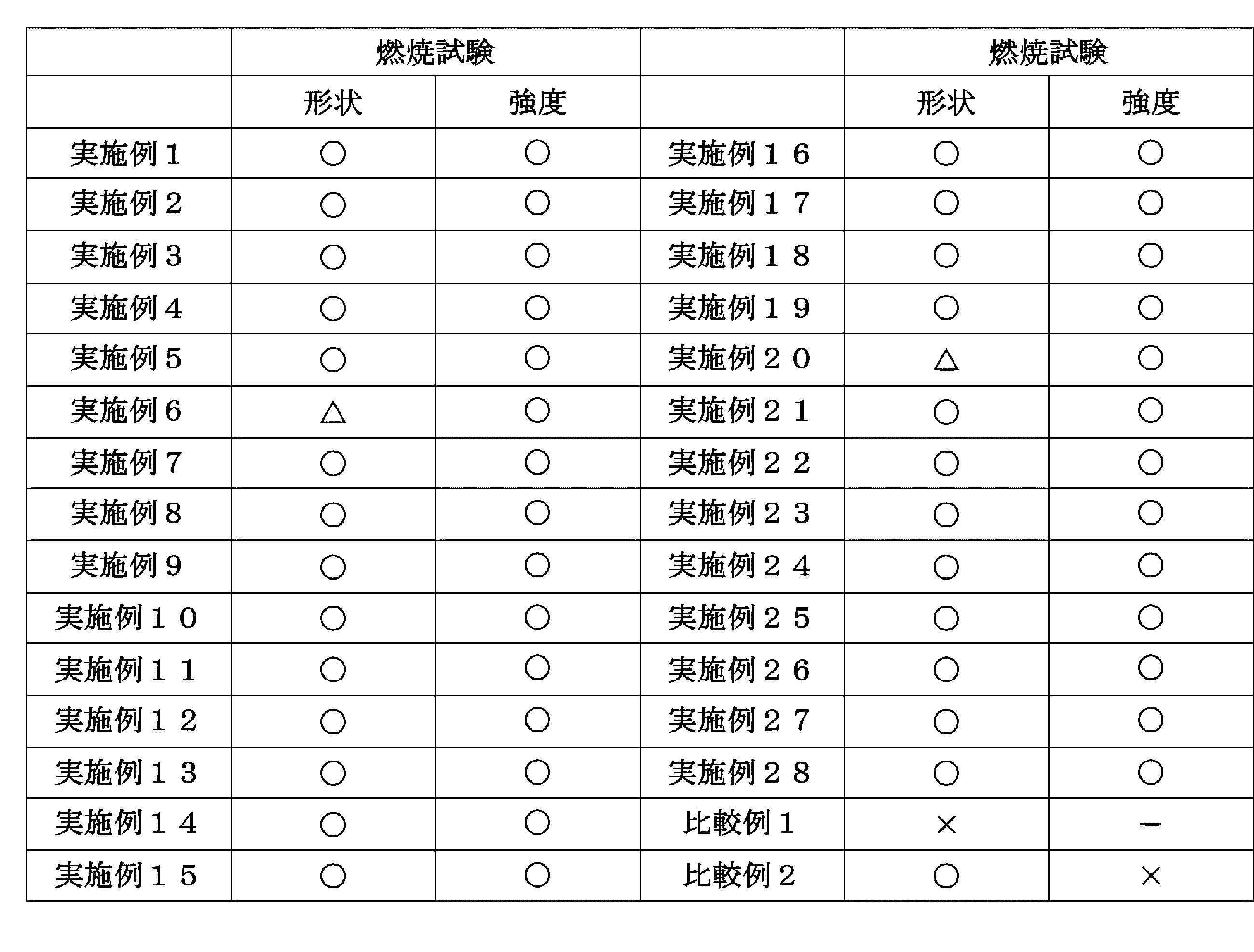
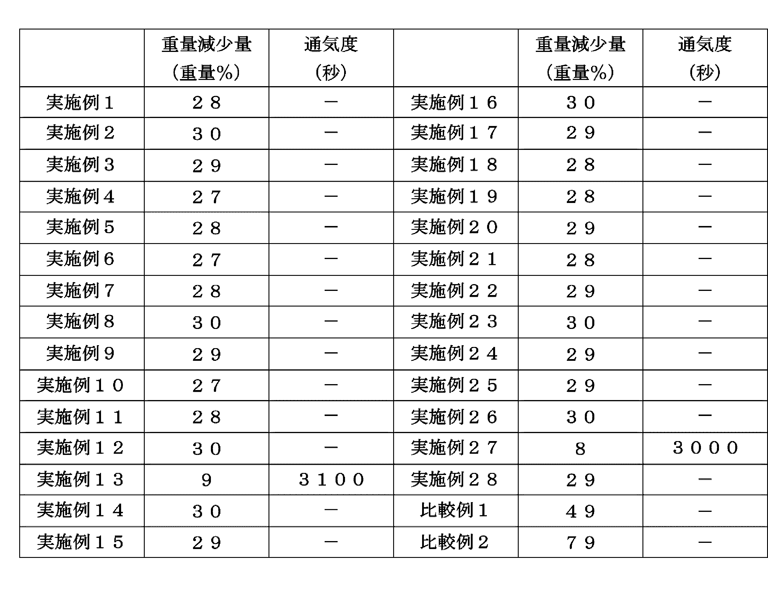
〔合成例31〕
撹拌機を備えた容器に、シリコーン樹脂(商品名:KE-1950-50A、信越化学工業製):50重量部、シリコーン樹脂(商品名:KE-1950-50B、信越化学工業製):50重量部、リン酸塩系ガラスフリット(商品名:VY0053M、日本フリット社製):200重量部、トルエン:128重量部を添加し、撹拌混合して、シリコーン樹脂組成物(S-1)を得た。
撹拌機を備えた容器に、シリコーン樹脂(商品名:KE-1950-50A、信越化学工業製):50重量部、シリコーン樹脂(商品名:KE-1950-50B、信越化学工業製):50重量部、リン酸塩系ガラスフリット(商品名:VY0053M、日本フリット社製):200重量部、トルエン:128重量部を添加し、撹拌混合して、シリコーン樹脂組成物(S-1)を得た。
〔合成例32〕
撹拌機を備えた容器に、シリコーン樹脂(商品名:KE-1950-50A、信越化学工業製):50重量部、シリコーン樹脂(商品名:KE-1950-50B、信越化学工業製):50重量部、ホウ珪酸塩系ガラスフリット(商品名:CY5600、日本フリット社製):200重量部、トルエン:128重量部を添加し、撹拌混合して、シリコーン樹脂組成物(S-2)を得た。
撹拌機を備えた容器に、シリコーン樹脂(商品名:KE-1950-50A、信越化学工業製):50重量部、シリコーン樹脂(商品名:KE-1950-50B、信越化学工業製):50重量部、ホウ珪酸塩系ガラスフリット(商品名:CY5600、日本フリット社製):200重量部、トルエン:128重量部を添加し、撹拌混合して、シリコーン樹脂組成物(S-2)を得た。
〔合成例33〕
撹拌機を備えた容器に、シリコーン樹脂(商品名:KE-1950-50A、信越化学工業製):50重量部、シリコーン樹脂(商品名:KE-1950-50B、信越化学工業製):50重量部、トルエン:128重量部を添加し、撹拌混合して、シリコーン樹脂組成物(K)を得た。
撹拌機を備えた容器に、シリコーン樹脂(商品名:KE-1950-50A、信越化学工業製):50重量部、シリコーン樹脂(商品名:KE-1950-50B、信越化学工業製):50重量部、トルエン:128重量部を添加し、撹拌混合して、シリコーン樹脂組成物(K)を得た。
〔実施例29〕
合成例31で得られたシリコーン樹脂組成物(S-1)を、ポリエチレンテレフタレートフィルム(厚さ:50μm、商品名:ルミラーS10、東レ社製)上に、テスター産業社製のアプリケーターを用いて、乾燥後の厚さが100μmになるように塗布し、その後、熱風循環式オーブンで、80℃で2分間、110℃で2分間加熱乾燥して、上記ポリエチレンテレフタレートフィルムを剥がすことにより、難燃性材料(29)を得た。結果を表3、表4に示した。
合成例31で得られたシリコーン樹脂組成物(S-1)を、ポリエチレンテレフタレートフィルム(厚さ:50μm、商品名:ルミラーS10、東レ社製)上に、テスター産業社製のアプリケーターを用いて、乾燥後の厚さが100μmになるように塗布し、その後、熱風循環式オーブンで、80℃で2分間、110℃で2分間加熱乾燥して、上記ポリエチレンテレフタレートフィルムを剥がすことにより、難燃性材料(29)を得た。結果を表3、表4に示した。
〔実施例30〕
合成例32で得られたシリコーン樹脂組成物(S-2)を、ポリエチレンテレフタレートフィルム(厚さ:50μm、商品名:ルミラーS10、東レ社製)上に、テスター産業社製のアプリケーターを用いて、乾燥後の厚さが100μmになるように塗布し、その後、熱風循環式オーブンで、80℃で2分間、110℃で2分間加熱乾燥して、上記ポリエチレンテレフタレートフィルムを剥がすことにより、難燃性材料(30)を得た。結果を表3、表4に示した。
合成例32で得られたシリコーン樹脂組成物(S-2)を、ポリエチレンテレフタレートフィルム(厚さ:50μm、商品名:ルミラーS10、東レ社製)上に、テスター産業社製のアプリケーターを用いて、乾燥後の厚さが100μmになるように塗布し、その後、熱風循環式オーブンで、80℃で2分間、110℃で2分間加熱乾燥して、上記ポリエチレンテレフタレートフィルムを剥がすことにより、難燃性材料(30)を得た。結果を表3、表4に示した。
〔比較例3〕
合成例33で得られたシリコーン樹脂組成物(K)を、ポリエチレンテレフタレートフィルム(厚さ:50μm、商品名:ルミラーS10、東レ社製)上に、テスター産業社製のアプリケーターを用いて、乾燥後の厚さが100μmになるように塗布し、その後、熱風循環式オーブンで、80℃で2分間、110℃で2分間加熱乾燥して、上記ポリエチレンテレフタレートフィルムを剥がすことにより、材料(C3)を得た。結果を表3、表4に示した。
合成例33で得られたシリコーン樹脂組成物(K)を、ポリエチレンテレフタレートフィルム(厚さ:50μm、商品名:ルミラーS10、東レ社製)上に、テスター産業社製のアプリケーターを用いて、乾燥後の厚さが100μmになるように塗布し、その後、熱風循環式オーブンで、80℃で2分間、110℃で2分間加熱乾燥して、上記ポリエチレンテレフタレートフィルムを剥がすことにより、材料(C3)を得た。結果を表3、表4に示した。
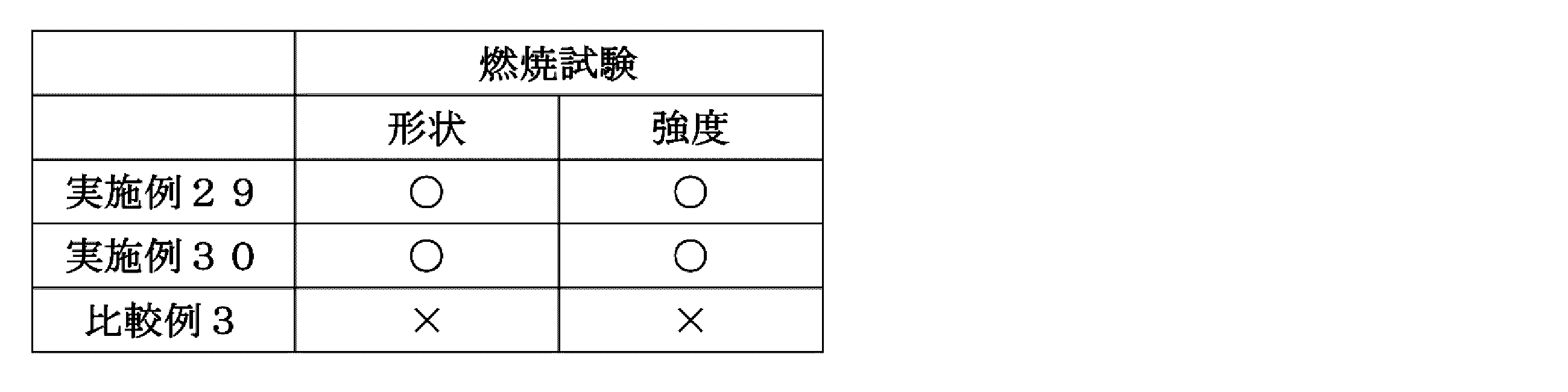

〔合成例34〕
撹拌機を備えた容器に、エポキシ系塗料(商品名:マイルドサビガード、エスケー化研社製):100重量部、シリカ(商品名:AEROSIL RX 200、日本アエロジル社製):10重量部、ガラスフリット(商品名:VY0053M、日本フリット社製):100重量部を添加し、撹拌混合して、塗料組成物(A-1)を得た。
撹拌機を備えた容器に、エポキシ系塗料(商品名:マイルドサビガード、エスケー化研社製):100重量部、シリカ(商品名:AEROSIL RX 200、日本アエロジル社製):10重量部、ガラスフリット(商品名:VY0053M、日本フリット社製):100重量部を添加し、撹拌混合して、塗料組成物(A-1)を得た。
〔合成例35〕
撹拌機を備えた容器に、エポキシ系塗料(商品名:マイルドサビガード、エスケー化研社製):100重量部、シリカ(商品名:AEROSIL RX 200、日本アエロジル社製):10重量部、ガラスフリット(商品名:VY0053M、日本フリット社製):200重量部を添加し、撹拌混合して、塗料組成物(A-2)を得た。
撹拌機を備えた容器に、エポキシ系塗料(商品名:マイルドサビガード、エスケー化研社製):100重量部、シリカ(商品名:AEROSIL RX 200、日本アエロジル社製):10重量部、ガラスフリット(商品名:VY0053M、日本フリット社製):200重量部を添加し、撹拌混合して、塗料組成物(A-2)を得た。
〔合成例36〕
撹拌機を備えた容器に、エポキシ系塗料(商品名:マイルドサビガード、エスケー化研社製):100重量部、シリカ(商品名:AEROSIL RX 200、日本アエロジル社製):10重量部、ガラスフリット(商品名:VY0053M、日本フリット社製):300重量部を添加し、撹拌混合して、塗料組成物(A-3)を得た。
撹拌機を備えた容器に、エポキシ系塗料(商品名:マイルドサビガード、エスケー化研社製):100重量部、シリカ(商品名:AEROSIL RX 200、日本アエロジル社製):10重量部、ガラスフリット(商品名:VY0053M、日本フリット社製):300重量部を添加し、撹拌混合して、塗料組成物(A-3)を得た。
〔合成例37〕
撹拌機を備えた容器に、ウレタン系塗料(商品名:レタンECOベーク、関西ペイント社製):100重量部、シリカ(商品名:AEROSIL RX 200、日本アエロジル社製):10重量部、ガラスフリット(商品名:VY0053M、日本フリット社製):100重量部を添加し、撹拌混合して、塗料組成物(B-1)を得た。
撹拌機を備えた容器に、ウレタン系塗料(商品名:レタンECOベーク、関西ペイント社製):100重量部、シリカ(商品名:AEROSIL RX 200、日本アエロジル社製):10重量部、ガラスフリット(商品名:VY0053M、日本フリット社製):100重量部を添加し、撹拌混合して、塗料組成物(B-1)を得た。
〔合成例38〕
撹拌機を備えた容器に、ウレタン系塗料(商品名:レタンECOベーク、エスケー化研社製):100重量部、シリカ(商品名:AEROSIL RX 200、日本アエロジル社製):10重量部、ガラスフリット(商品名:VY0053M、日本フリット社製):200重量部を添加し、撹拌混合して、塗料組成物(B-2)を得た。
撹拌機を備えた容器に、ウレタン系塗料(商品名:レタンECOベーク、エスケー化研社製):100重量部、シリカ(商品名:AEROSIL RX 200、日本アエロジル社製):10重量部、ガラスフリット(商品名:VY0053M、日本フリット社製):200重量部を添加し、撹拌混合して、塗料組成物(B-2)を得た。
〔合成例39〕
撹拌機を備えた容器に、ウレタン系塗料(商品名:レタンECOベーク、エスケー化研社製):100重量部、シリカ(商品名:AEROSIL RX 200、日本アエロジル社製):10重量部、ガラスフリット(商品名:VY0053M、日本フリット社製):300重量部を添加し、撹拌混合して、塗料組成物(B-3)を得た。
撹拌機を備えた容器に、ウレタン系塗料(商品名:レタンECOベーク、エスケー化研社製):100重量部、シリカ(商品名:AEROSIL RX 200、日本アエロジル社製):10重量部、ガラスフリット(商品名:VY0053M、日本フリット社製):300重量部を添加し、撹拌混合して、塗料組成物(B-3)を得た。
〔合成例40〕
撹拌機を備えた容器に、フッ素系系塗料(商品名:スーパーオーデフレッシュF、日本ペイント社製):100重量部、シリカ(商品名:AEROSIL RX 200、日本アエロジル社製):10重量部、ガラスフリット(商品名:VY0053M、日本フリット社製):100重量部を添加し、撹拌混合して、塗料組成物(C-1)を得た。
撹拌機を備えた容器に、フッ素系系塗料(商品名:スーパーオーデフレッシュF、日本ペイント社製):100重量部、シリカ(商品名:AEROSIL RX 200、日本アエロジル社製):10重量部、ガラスフリット(商品名:VY0053M、日本フリット社製):100重量部を添加し、撹拌混合して、塗料組成物(C-1)を得た。
〔合成例41〕
撹拌機を備えた容器に、フッ素系塗料(商品名:スーパーオーデフレッシュF、日本ペイント社製):100重量部、シリカ(商品名:AEROSIL RX 200、日本アエロジル社製):10重量部、ガラスフリット(商品名:VY0053M、日本フリット社製):200重量部を添加し、撹拌混合して、塗料組成物(C-2)を得た。
撹拌機を備えた容器に、フッ素系塗料(商品名:スーパーオーデフレッシュF、日本ペイント社製):100重量部、シリカ(商品名:AEROSIL RX 200、日本アエロジル社製):10重量部、ガラスフリット(商品名:VY0053M、日本フリット社製):200重量部を添加し、撹拌混合して、塗料組成物(C-2)を得た。
〔合成例42〕
撹拌機を備えた容器に、アクリル系塗料(商品名:ニッペロードライン1000、日本ペイント社製):100重量部、シリカ(商品名:AEROSIL RX 200、日本アエロジル社製):10重量部、ガラスフリット(商品名:VY0053M、日本フリット社製):100重量部を添加し、撹拌混合して、塗料組成物(D-1)を得た。
撹拌機を備えた容器に、アクリル系塗料(商品名:ニッペロードライン1000、日本ペイント社製):100重量部、シリカ(商品名:AEROSIL RX 200、日本アエロジル社製):10重量部、ガラスフリット(商品名:VY0053M、日本フリット社製):100重量部を添加し、撹拌混合して、塗料組成物(D-1)を得た。
〔合成例43〕
撹拌機を備えた容器に、アクリル系塗料(商品名:ニッペロードライン、日本ペイント社製):100重量部、シリカ(商品名:AEROSIL RX 200、日本アエロジル社製):10重量部、ガラスフリット(商品名:VY0053M、日本フリット社製):200重量部を添加し、撹拌混合して、塗料組成物(D-2)を得た。
撹拌機を備えた容器に、アクリル系塗料(商品名:ニッペロードライン、日本ペイント社製):100重量部、シリカ(商品名:AEROSIL RX 200、日本アエロジル社製):10重量部、ガラスフリット(商品名:VY0053M、日本フリット社製):200重量部を添加し、撹拌混合して、塗料組成物(D-2)を得た。
〔合成例44〕
撹拌機を備えた容器に、シリコーン系塗料(商品名:スーパーオーデフレッシュSi、日本ペイント社製):100重量部、ガラスフリット(商品名:VY0053M、日本フリット社製):100重量部を添加し、撹拌混合して、塗料組成物(E-1)を得た。
撹拌機を備えた容器に、シリコーン系塗料(商品名:スーパーオーデフレッシュSi、日本ペイント社製):100重量部、ガラスフリット(商品名:VY0053M、日本フリット社製):100重量部を添加し、撹拌混合して、塗料組成物(E-1)を得た。
〔合成例45〕
撹拌機を備えた容器に、シリコーン系塗料(商品名:スーパーオーデフレッシュSi、日本ペイント社製):100重量部、ガラスフリット(商品名:VY0053M、日本フリット社製):200重量部を添加し、撹拌混合して、塗料組成物(E-2)を得た。
撹拌機を備えた容器に、シリコーン系塗料(商品名:スーパーオーデフレッシュSi、日本ペイント社製):100重量部、ガラスフリット(商品名:VY0053M、日本フリット社製):200重量部を添加し、撹拌混合して、塗料組成物(E-2)を得た。
〔実施例31〕
合成例34で得られた塗料組成物(A-1)を、ポリエチレンテレフタレートフィルム(厚さ:50μm、商品名:ダイアホイルMRS、三菱ケミカル社製)上に、テスター産業社製のアプリケーターを用いて、乾燥後の厚さが100μmになるように塗布し、その後、熱風循環式オーブンで、100℃で30分間加熱乾燥して、上記ポリエチレンテレフタレートフィルムを剥がすことにより、難燃性材料(31)を得た。結果を表5、表6に示した。
合成例34で得られた塗料組成物(A-1)を、ポリエチレンテレフタレートフィルム(厚さ:50μm、商品名:ダイアホイルMRS、三菱ケミカル社製)上に、テスター産業社製のアプリケーターを用いて、乾燥後の厚さが100μmになるように塗布し、その後、熱風循環式オーブンで、100℃で30分間加熱乾燥して、上記ポリエチレンテレフタレートフィルムを剥がすことにより、難燃性材料(31)を得た。結果を表5、表6に示した。
〔実施例32〕
合成例35で得られた塗料組成物(A-2)を、ポリエチレンテレフタレートフィルム(厚さ:50μm、商品名:ダイアホイルMRS、三菱ケミカル社製)上に、テスター産業社製のアプリケーターを用いて、乾燥後の厚さが100μmになるように塗布し、その後、熱風循環式オーブンで、100℃で30分間加熱乾燥して、上記ポリエチレンテレフタレートフィルムを剥がすことにより、難燃性材料(32)を得た。結果を表5、表6に示した。
合成例35で得られた塗料組成物(A-2)を、ポリエチレンテレフタレートフィルム(厚さ:50μm、商品名:ダイアホイルMRS、三菱ケミカル社製)上に、テスター産業社製のアプリケーターを用いて、乾燥後の厚さが100μmになるように塗布し、その後、熱風循環式オーブンで、100℃で30分間加熱乾燥して、上記ポリエチレンテレフタレートフィルムを剥がすことにより、難燃性材料(32)を得た。結果を表5、表6に示した。
〔実施例33〕
合成例36で得られた塗料組成物(A-3)を、ポリエチレンテレフタレートフィルム(厚さ:50μm、商品名:ダイアホイルMRS、三菱ケミカル社製)上に、テスター産業社製のアプリケーターを用いて、乾燥後の厚さが100μmになるように塗布し、その後、熱風循環式オーブンで、100℃で30分間加熱乾燥して、上記ポリエチレンテレフタレートフィルムを剥がすことにより、難燃性材料(33)を得た。結果を表5、表6に示した。
合成例36で得られた塗料組成物(A-3)を、ポリエチレンテレフタレートフィルム(厚さ:50μm、商品名:ダイアホイルMRS、三菱ケミカル社製)上に、テスター産業社製のアプリケーターを用いて、乾燥後の厚さが100μmになるように塗布し、その後、熱風循環式オーブンで、100℃で30分間加熱乾燥して、上記ポリエチレンテレフタレートフィルムを剥がすことにより、難燃性材料(33)を得た。結果を表5、表6に示した。
〔実施例34〕
合成例37で得られた塗料組成物(B-1)を、ポリエチレンテレフタレートフィルム(厚さ:50μm、商品名:ダイアホイルMRS、三菱ケミカル社製)上に、テスター産業社製のアプリケーターを用いて、乾燥後の厚さが100μmになるように塗布し、その後、熱風循環式オーブンで、100℃で30分間加熱乾燥して、上記ポリエチレンテレフタレートフィルムを剥がすことにより、難燃性材料(34)を得た。結果を表5、表6に示した。
合成例37で得られた塗料組成物(B-1)を、ポリエチレンテレフタレートフィルム(厚さ:50μm、商品名:ダイアホイルMRS、三菱ケミカル社製)上に、テスター産業社製のアプリケーターを用いて、乾燥後の厚さが100μmになるように塗布し、その後、熱風循環式オーブンで、100℃で30分間加熱乾燥して、上記ポリエチレンテレフタレートフィルムを剥がすことにより、難燃性材料(34)を得た。結果を表5、表6に示した。
〔実施例35〕
合成例38で得られた塗料組成物(B-2)を、ポリエチレンテレフタレートフィルム(厚さ:50μm、商品名:ダイアホイルMRS、三菱ケミカル社製)上に、テスター産業社製のアプリケーターを用いて、乾燥後の厚さが100μmになるように塗布し、その後、熱風循環式オーブンで、100℃で30分間加熱乾燥して、上記ポリエチレンテレフタレートフィルムを剥がすことにより、難燃性材料(35)を得た。結果を表5、表6に示した。
合成例38で得られた塗料組成物(B-2)を、ポリエチレンテレフタレートフィルム(厚さ:50μm、商品名:ダイアホイルMRS、三菱ケミカル社製)上に、テスター産業社製のアプリケーターを用いて、乾燥後の厚さが100μmになるように塗布し、その後、熱風循環式オーブンで、100℃で30分間加熱乾燥して、上記ポリエチレンテレフタレートフィルムを剥がすことにより、難燃性材料(35)を得た。結果を表5、表6に示した。
〔実施例36〕
合成例39で得られた塗料組成物(B-3)を、ポリエチレンテレフタレートフィルム(厚さ:50μm、商品名:ダイアホイルMRS、三菱ケミカル社製)上に、テスター産業社製のアプリケーターを用いて、乾燥後の厚さが100μmになるように塗布し、その後、熱風循環式オーブンで、100℃で30分間加熱乾燥して、上記ポリエチレンテレフタレートフィルムを剥がすことにより、難燃性材料(36)を得た。結果を表5、表6に示した。
合成例39で得られた塗料組成物(B-3)を、ポリエチレンテレフタレートフィルム(厚さ:50μm、商品名:ダイアホイルMRS、三菱ケミカル社製)上に、テスター産業社製のアプリケーターを用いて、乾燥後の厚さが100μmになるように塗布し、その後、熱風循環式オーブンで、100℃で30分間加熱乾燥して、上記ポリエチレンテレフタレートフィルムを剥がすことにより、難燃性材料(36)を得た。結果を表5、表6に示した。
〔実施例37〕
合成例40で得られた塗料組成物(C-1)を、ポリエチレンテレフタレートフィルム(厚さ:50μm、商品名:ダイアホイルMRF、三菱ケミカル社製)上に、テスター産業社製のアプリケーターを用いて、乾燥後の厚さが100μmになるように塗布し、その後、熱風循環式オーブンで、100℃で30分間加熱乾燥して、上記ポリエチレンテレフタレートフィルムを剥がすことにより、難燃性材料(37)を得た。結果を表5、表6に示した。
合成例40で得られた塗料組成物(C-1)を、ポリエチレンテレフタレートフィルム(厚さ:50μm、商品名:ダイアホイルMRF、三菱ケミカル社製)上に、テスター産業社製のアプリケーターを用いて、乾燥後の厚さが100μmになるように塗布し、その後、熱風循環式オーブンで、100℃で30分間加熱乾燥して、上記ポリエチレンテレフタレートフィルムを剥がすことにより、難燃性材料(37)を得た。結果を表5、表6に示した。
〔実施例38〕
合成例41で得られた塗料組成物(C-2)を、ポリエチレンテレフタレートフィルム(厚さ:50μm、商品名:ダイアホイルMRF、三菱ケミカル社製)上に、テスター産業社製のアプリケーターを用いて、乾燥後の厚さが100μmになるように塗布し、その後、熱風循環式オーブンで、100℃で30分間加熱乾燥して、上記ポリエチレンテレフタレートフィルムを剥がすことにより、難燃性材料(38)を得た。結果を表5、表6に示した。
合成例41で得られた塗料組成物(C-2)を、ポリエチレンテレフタレートフィルム(厚さ:50μm、商品名:ダイアホイルMRF、三菱ケミカル社製)上に、テスター産業社製のアプリケーターを用いて、乾燥後の厚さが100μmになるように塗布し、その後、熱風循環式オーブンで、100℃で30分間加熱乾燥して、上記ポリエチレンテレフタレートフィルムを剥がすことにより、難燃性材料(38)を得た。結果を表5、表6に示した。
〔実施例39〕
合成例42で得られた塗料組成物(D-1)を、ポリエチレンテレフタレートフィルム(厚さ:50μm、商品名:ダイアホイルMRS、三菱ケミカル社製)上に、テスター産業社製のアプリケーターを用いて、乾燥後の厚さが100μmになるように塗布し、その後、熱風循環式オーブンで、100℃で30分間加熱乾燥して、上記ポリエチレンテレフタレートフィルムを剥がすことにより、難燃性材料(39)を得た。結果を表5、表6に示した。
合成例42で得られた塗料組成物(D-1)を、ポリエチレンテレフタレートフィルム(厚さ:50μm、商品名:ダイアホイルMRS、三菱ケミカル社製)上に、テスター産業社製のアプリケーターを用いて、乾燥後の厚さが100μmになるように塗布し、その後、熱風循環式オーブンで、100℃で30分間加熱乾燥して、上記ポリエチレンテレフタレートフィルムを剥がすことにより、難燃性材料(39)を得た。結果を表5、表6に示した。
〔実施例40〕
合成例43で得られた塗料組成物(D-2)を、ポリエチレンテレフタレートフィルム(厚さ:50μm、商品名:ダイアホイルMRS、三菱ケミカル社製)上に、テスター産業社製のアプリケーターを用いて、乾燥後の厚さが100μmになるように塗布し、その後、熱風循環式オーブンで、100℃で30分間加熱乾燥して、上記ポリエチレンテレフタレートフィルムを剥がすことにより、難燃性材料(40)を得た。結果を表5、表6に示した。
合成例43で得られた塗料組成物(D-2)を、ポリエチレンテレフタレートフィルム(厚さ:50μm、商品名:ダイアホイルMRS、三菱ケミカル社製)上に、テスター産業社製のアプリケーターを用いて、乾燥後の厚さが100μmになるように塗布し、その後、熱風循環式オーブンで、100℃で30分間加熱乾燥して、上記ポリエチレンテレフタレートフィルムを剥がすことにより、難燃性材料(40)を得た。結果を表5、表6に示した。
〔実施例41〕
合成例44で得られた塗料組成物(E-1)を、ポリエチレンテレフタレートフィルム(厚さ:50μm、商品名:ダイアホイルMRS、三菱ケミカル社製)上に、テスター産業社製のアプリケーターを用いて、乾燥後の厚さが100μmになるように塗布し、その後、熱風循環式オーブンで、100℃で30分間加熱乾燥して、上記ポリエチレンテレフタレートフィルムを剥がすことにより、難燃性材料(41)を得た。結果を表5、表6に示した。
合成例44で得られた塗料組成物(E-1)を、ポリエチレンテレフタレートフィルム(厚さ:50μm、商品名:ダイアホイルMRS、三菱ケミカル社製)上に、テスター産業社製のアプリケーターを用いて、乾燥後の厚さが100μmになるように塗布し、その後、熱風循環式オーブンで、100℃で30分間加熱乾燥して、上記ポリエチレンテレフタレートフィルムを剥がすことにより、難燃性材料(41)を得た。結果を表5、表6に示した。
〔実施例42〕
合成例45で得られた塗料組成物(E-2)を、ポリエチレンテレフタレートフィルム(厚さ:50μm、商品名:ダイアホイルMRS、三菱ケミカル社製)上に、テスター産業社製のアプリケーターを用いて、乾燥後の厚さが100μmになるように塗布し、その後、熱風循環式オーブンで、100℃で30分間加熱乾燥して、上記ポリエチレンテレフタレートフィルムを剥がすことにより、難燃性材料(42)を得た。結果を表5、表6に示した。
合成例45で得られた塗料組成物(E-2)を、ポリエチレンテレフタレートフィルム(厚さ:50μm、商品名:ダイアホイルMRS、三菱ケミカル社製)上に、テスター産業社製のアプリケーターを用いて、乾燥後の厚さが100μmになるように塗布し、その後、熱風循環式オーブンで、100℃で30分間加熱乾燥して、上記ポリエチレンテレフタレートフィルムを剥がすことにより、難燃性材料(42)を得た。結果を表5、表6に示した。
〔比較例4〕
エポキシ系塗料(商品名:マイルドサビガード、エスケー化研社製)を、ポリエチレンテレフタレートフィルム(厚さ:50μm、商品名:ダイアホイルMRS、三菱ケミカル社製)上に、テスター産業社製のアプリケーターを用いて、乾燥後の厚さが100μmになるように塗布し、その後、熱風循環式オーブンで、100℃で30分間加熱乾燥して、上記ポリエチレンテレフタレートフィルムを剥がすことにより、材料(C4)を得た。結果を表5、表6に示した。
エポキシ系塗料(商品名:マイルドサビガード、エスケー化研社製)を、ポリエチレンテレフタレートフィルム(厚さ:50μm、商品名:ダイアホイルMRS、三菱ケミカル社製)上に、テスター産業社製のアプリケーターを用いて、乾燥後の厚さが100μmになるように塗布し、その後、熱風循環式オーブンで、100℃で30分間加熱乾燥して、上記ポリエチレンテレフタレートフィルムを剥がすことにより、材料(C4)を得た。結果を表5、表6に示した。
〔比較例5〕
ウレタン系塗料(商品名:レタンECOベーク、関西ペイント社製)を、ポリエチレンテレフタレートフィルム(厚さ:50μm、商品名:ダイアホイルMRS、三菱ケミカル社製)上に、テスター産業社製のアプリケーターを用いて、乾燥後の厚さが100μmになるように塗布し、その後、熱風循環式オーブンで、100℃で30分間加熱乾燥して、上記ポリエチレンテレフタレートフィルムを剥がすことにより、材料(C5)を得た。結果を表5、表6に示した。
ウレタン系塗料(商品名:レタンECOベーク、関西ペイント社製)を、ポリエチレンテレフタレートフィルム(厚さ:50μm、商品名:ダイアホイルMRS、三菱ケミカル社製)上に、テスター産業社製のアプリケーターを用いて、乾燥後の厚さが100μmになるように塗布し、その後、熱風循環式オーブンで、100℃で30分間加熱乾燥して、上記ポリエチレンテレフタレートフィルムを剥がすことにより、材料(C5)を得た。結果を表5、表6に示した。
〔比較例6〕
フッ素系系塗料(商品名:スーパーオーデフレッシュF、日本ペイント社製)を、ポリエチレンテレフタレートフィルム(厚さ:50μm、商品名:ダイアホイルMRS、三菱ケミカル社製)上に、テスター産業社製のアプリケーターを用いて、乾燥後の厚さが100μmになるように塗布し、その後、熱風循環式オーブンで、100℃で30分間加熱乾燥して、上記ポリエチレンテレフタレートフィルムを剥がすことにより、材料(C6)を得た。結果を表5、表6に示した。
フッ素系系塗料(商品名:スーパーオーデフレッシュF、日本ペイント社製)を、ポリエチレンテレフタレートフィルム(厚さ:50μm、商品名:ダイアホイルMRS、三菱ケミカル社製)上に、テスター産業社製のアプリケーターを用いて、乾燥後の厚さが100μmになるように塗布し、その後、熱風循環式オーブンで、100℃で30分間加熱乾燥して、上記ポリエチレンテレフタレートフィルムを剥がすことにより、材料(C6)を得た。結果を表5、表6に示した。
〔比較例7〕
アクリル系塗料(商品名:ニッペロードライン1000、日本ペイント社製)を、ポリエチレンテレフタレートフィルム(厚さ:50μm、商品名:ダイアホイルMRS、三菱ケミカル社製)上に、テスター産業社製のアプリケーターを用いて、乾燥後の厚さが100μmになるように塗布し、その後、熱風循環式オーブンで、100℃で30分間加熱乾燥して、上記ポリエチレンテレフタレートフィルムを剥がすことにより、材料(C7)を得た。結果を表5、表6に示した。
アクリル系塗料(商品名:ニッペロードライン1000、日本ペイント社製)を、ポリエチレンテレフタレートフィルム(厚さ:50μm、商品名:ダイアホイルMRS、三菱ケミカル社製)上に、テスター産業社製のアプリケーターを用いて、乾燥後の厚さが100μmになるように塗布し、その後、熱風循環式オーブンで、100℃で30分間加熱乾燥して、上記ポリエチレンテレフタレートフィルムを剥がすことにより、材料(C7)を得た。結果を表5、表6に示した。
〔比較例8〕
シリコーン系塗料(商品名:スーパーオーデフレッシュSi、日本ペイント社製)を、ポリエチレンテレフタレートフィルム(厚さ:50μm、商品名:ダイアホイルMRS、三菱ケミカル社製)上に、テスター産業社製のアプリケーターを用いて、乾燥後の厚さが100μmになるように塗布し、その後、熱風循環式オーブンで、100℃で30分間加熱乾燥して、上記ポリエチレンテレフタレートフィルムを剥がすことにより、材料(C8)を得た。結果を表5、表6に示した。
シリコーン系塗料(商品名:スーパーオーデフレッシュSi、日本ペイント社製)を、ポリエチレンテレフタレートフィルム(厚さ:50μm、商品名:ダイアホイルMRS、三菱ケミカル社製)上に、テスター産業社製のアプリケーターを用いて、乾燥後の厚さが100μmになるように塗布し、その後、熱風循環式オーブンで、100℃で30分間加熱乾燥して、上記ポリエチレンテレフタレートフィルムを剥がすことにより、材料(C8)を得た。結果を表5、表6に示した。


本発明の難燃性材料は、例えば、鉄道車両、航空機、自動車、船舶、エレベーター、エスカレーターなどの輸送機の内装部材(輸送機用内装部材)、輸送機用外装部材、建築材料部材、ディスプレイ部材、家電部材、電子回路部材、照明カバーとして好適に利用できる。
Claims (16)
- バインダー樹脂、低融点無機物、高融点無機物を有する樹脂組成物(A)から形成される難燃性材料。
- 前記バインダー樹脂100重量部に対する前記低融点無機物の含有割合が、固形分換算で、100重量部~500重量部である、請求項1に記載の難燃性材料。
- 前記バインダー樹脂100重量部に対する前記高融点無機物の含有割合が、固形分換算で、10重量部~100重量部である、請求項1または2に記載の難燃性材料。
- 前記樹脂組成物(A)中の、前記バインダー樹脂と前記低融点無機物と前記高融点無機物の合計の含有割合が、固形分換算で、80重量%~100重量%である、請求項1から3までのいずれかに記載の難燃性材料。
- 厚みが20μm~3000μmのシート状である、請求項1から4までのいずれかに記載の難燃性材料。
- 前記バインダー樹脂が、熱可塑性樹脂、熱硬化性樹脂、ゴムから選ばれる少なくとも1種である、請求項1から5までのいずれかに記載の難燃性材料。
- 前記低融点無機物がガラスフリットである、請求項1から6までのいずれかに記載の難燃性材料。
- 前記ガラスフリットが、リン酸塩系ガラスフリット、ホウ珪酸塩系ガラスフリット、ビスマス系ガラスフリットから選ばれる少なくとも1種である、請求項7に記載の難燃性材料。
- 前記高融点無機物が、窒化ホウ素、アルミナ、酸化亜鉛、酸化チタン、シリカ、チタン酸バリウム、炭酸カルシウム、ガラスビーズ、水酸化アルミニウム、シリコーンパウダー、ガラスバルーン、シリカバルーン、タルクから選ばれる少なくとも1種である、請求項1から8までのいずれかに記載の難燃性材料。
- 加熱によって高融点無機物を生成するバインダー樹脂および低融点無機物を有する樹脂組成物(B)から形成される、難燃性材料。
- 前記加熱によって高融点無機物を生成するバインダー樹脂100重量部に対する前記低融点無機物の含有割合が、固形分換算で、100重量部~500重量部である、請求項10に記載の難燃性材料。
- 前記樹脂組成物(B)中の、前記加熱によって高融点無機物を生成するバインダー樹脂と前記低融点無機物との合計の含有割合が、固形分換算で、80重量%~100重量%である、請求項10または11に記載の難燃性材料。
- 厚みが20μm~3000μmのシート状である、請求項10から12までのいずれかに記載の難燃性材料。
- 前記加熱によって高融点無機物を生成するバインダー樹脂が、シリコーン樹脂である、請求項10から13までのいずれかに記載の難燃性材料。
- 前記低融点無機物がガラスフリットである、請求項10から14までのいずれかに記載の難燃性材料。
- 前記ガラスフリットが、リン酸塩系ガラスフリット、ホウ珪酸塩系ガラスフリット、ビスマス系ガラスフリットから選ばれる少なくとも1種である、請求項15に記載の難燃性材料。
Priority Applications (3)
| Application Number | Priority Date | Filing Date | Title |
|---|---|---|---|
| EP19824980.7A EP3816234A4 (en) | 2018-06-27 | 2019-06-18 | FIRE RETARDANT MATERIAL |
| CN201980043339.0A CN112334545A (zh) | 2018-06-27 | 2019-06-18 | 阻燃性材料 |
| US17/050,983 US20210230483A1 (en) | 2018-06-27 | 2019-06-18 | Flame retardant material |
Applications Claiming Priority (4)
| Application Number | Priority Date | Filing Date | Title |
|---|---|---|---|
| JP2018121864 | 2018-06-27 | ||
| JP2018-121864 | 2018-06-27 | ||
| JP2019-105773 | 2019-06-06 | ||
| JP2019105773A JP7465633B2 (ja) | 2018-06-27 | 2019-06-06 | 難燃性材料 |
Publications (1)
| Publication Number | Publication Date |
|---|---|
| WO2020004119A1 true WO2020004119A1 (ja) | 2020-01-02 |
Family
ID=68986560
Family Applications (1)
| Application Number | Title | Priority Date | Filing Date |
|---|---|---|---|
| PCT/JP2019/023988 WO2020004119A1 (ja) | 2018-06-27 | 2019-06-18 | 難燃性材料 |
Country Status (2)
| Country | Link |
|---|---|
| EP (1) | EP3816234A4 (ja) |
| WO (1) | WO2020004119A1 (ja) |
Cited By (1)
| Publication number | Priority date | Publication date | Assignee | Title |
|---|---|---|---|---|
| WO2021124717A1 (ja) * | 2019-12-19 | 2021-06-24 | 日東電工株式会社 | 難燃断熱材料および難燃断熱材 |
Citations (8)
| Publication number | Priority date | Publication date | Assignee | Title |
|---|---|---|---|---|
| JPH07186333A (ja) | 1993-12-27 | 1995-07-25 | Asahi Pen:Kk | 難燃性化粧材料及び難燃性塗料組成物 |
| JP2002270047A (ja) * | 2001-03-08 | 2002-09-20 | Fujikura Ltd | 耐火ケーブル |
| JP2003100149A (ja) * | 2001-09-20 | 2003-04-04 | Fujikura Ltd | シリコーン樹脂組成物およびそれを用いた低圧耐火ケーブル |
| JP4491778B2 (ja) | 2004-06-04 | 2010-06-30 | 日東紡績株式会社 | 光拡散シート及びその製造方法 |
| JP4539349B2 (ja) | 2005-02-01 | 2010-09-08 | 日東紡績株式会社 | ガラス繊維シート及びその製造方法 |
| JP2014231597A (ja) | 2013-05-01 | 2014-12-11 | 日東電工株式会社 | 難燃複合部材 |
| JP2016027069A (ja) * | 2014-06-26 | 2016-02-18 | 日東電工株式会社 | 難燃材料およびその用途 |
| JP2018039997A (ja) * | 2016-08-31 | 2018-03-15 | 積水フーラー株式会社 | 硬化性組成物 |
Family Cites Families (5)
| Publication number | Priority date | Publication date | Assignee | Title |
|---|---|---|---|---|
| US5173960A (en) * | 1992-03-06 | 1992-12-22 | At&T Bell Laboratories | Cable having superior resistance to flame spread and smoke evolution |
| GB9214510D0 (en) * | 1992-07-08 | 1992-08-19 | Ferodo Caernarfon Ltd | Fireretardant material |
| WO2003094176A1 (en) * | 2002-04-29 | 2003-11-13 | Pirelli & C. S.P.A. | Fire resistant cable |
| JP6122332B2 (ja) * | 2012-04-11 | 2017-04-26 | 日東電工株式会社 | 難燃性シリコーン樹脂組成物及び難燃性シリコーン樹脂シート |
| CN107286518A (zh) * | 2017-07-31 | 2017-10-24 | 东莞市安拓普塑胶聚合物科技有限公司 | 一种低烟阻燃可陶瓷化pvc材料及其制备方法和应用 |
-
2019
- 2019-06-18 WO PCT/JP2019/023988 patent/WO2020004119A1/ja unknown
- 2019-06-18 EP EP19824980.7A patent/EP3816234A4/en active Pending
Patent Citations (8)
| Publication number | Priority date | Publication date | Assignee | Title |
|---|---|---|---|---|
| JPH07186333A (ja) | 1993-12-27 | 1995-07-25 | Asahi Pen:Kk | 難燃性化粧材料及び難燃性塗料組成物 |
| JP2002270047A (ja) * | 2001-03-08 | 2002-09-20 | Fujikura Ltd | 耐火ケーブル |
| JP2003100149A (ja) * | 2001-09-20 | 2003-04-04 | Fujikura Ltd | シリコーン樹脂組成物およびそれを用いた低圧耐火ケーブル |
| JP4491778B2 (ja) | 2004-06-04 | 2010-06-30 | 日東紡績株式会社 | 光拡散シート及びその製造方法 |
| JP4539349B2 (ja) | 2005-02-01 | 2010-09-08 | 日東紡績株式会社 | ガラス繊維シート及びその製造方法 |
| JP2014231597A (ja) | 2013-05-01 | 2014-12-11 | 日東電工株式会社 | 難燃複合部材 |
| JP2016027069A (ja) * | 2014-06-26 | 2016-02-18 | 日東電工株式会社 | 難燃材料およびその用途 |
| JP2018039997A (ja) * | 2016-08-31 | 2018-03-15 | 積水フーラー株式会社 | 硬化性組成物 |
Non-Patent Citations (1)
| Title |
|---|
| See also references of EP3816234A4 |
Cited By (1)
| Publication number | Priority date | Publication date | Assignee | Title |
|---|---|---|---|---|
| WO2021124717A1 (ja) * | 2019-12-19 | 2021-06-24 | 日東電工株式会社 | 難燃断熱材料および難燃断熱材 |
Also Published As
| Publication number | Publication date |
|---|---|
| EP3816234A1 (en) | 2021-05-05 |
| EP3816234A4 (en) | 2022-01-26 |
Similar Documents
| Publication | Publication Date | Title |
|---|---|---|
| Comyn | Adhesion science | |
| JP7288397B2 (ja) | 難燃断熱シートおよび難燃断熱材 | |
| EP2993038A1 (en) | Flame-resistant composite member | |
| JP2023133422A (ja) | 難燃性材料 | |
| WO2020004119A1 (ja) | 難燃性材料 | |
| KR20170037227A (ko) | 내마모성, 부착성, 내열성 및 내부식성을 향상시킨 절연코팅제 | |
| JP2020007533A (ja) | 難燃性材料 | |
| JP2020007535A (ja) | 難燃性材料 | |
| WO2020004120A1 (ja) | 難燃性塗膜 | |
| MX2015003733A (es) | Etiqueta negra de poliimida para baterias. | |
| JP7356893B2 (ja) | 難燃断熱材料および難燃断熱材 | |
| WO2020059456A1 (ja) | 難燃性シリコーン樹脂シート、粘着剤層付難燃性シリコーン樹脂シート、および、基材層付難燃性シリコーン樹脂シート | |
| JP2009185107A (ja) | 親水性塗料と親水性塗布体 | |
| KR20170118770A (ko) | 오일 시일용 코팅제 | |
| RU2675369C2 (ru) | Барьерный слой и его применение в системах покрытий на основах из полимера | |
| JP7341792B2 (ja) | 難燃性シリコーン樹脂シート、粘着剤層付難燃性シリコーン樹脂シート、および、基材層付難燃性シリコーン樹脂シート | |
| TWI819112B (zh) | 塗裝金屬板及其製造方法 | |
| JP2013127070A (ja) | 親水性塗料と親水性塗布体 | |
| CN110691822B (zh) | 涂料膜、涂料组合物及具有该涂料膜的物品 | |
| JP2000034427A (ja) | 水性汚れ付着防止樹脂材料 | |
| JP2020069664A (ja) | 離型シートおよびその製造方法 | |
| JPH04239077A (ja) | 耐熱性塗料 |
Legal Events
| Date | Code | Title | Description |
|---|---|---|---|
| 121 | Ep: the epo has been informed by wipo that ep was designated in this application |
Ref document number: 19824980 Country of ref document: EP Kind code of ref document: A1 |
|
| NENP | Non-entry into the national phase |
Ref country code: DE |
|
| ENP | Entry into the national phase |
Ref document number: 2019824980 Country of ref document: EP Effective date: 20210127 |