WO2020004084A1 - 清掃具用スタンド - Google Patents
清掃具用スタンド Download PDFInfo
- Publication number
- WO2020004084A1 WO2020004084A1 PCT/JP2019/023735 JP2019023735W WO2020004084A1 WO 2020004084 A1 WO2020004084 A1 WO 2020004084A1 JP 2019023735 W JP2019023735 W JP 2019023735W WO 2020004084 A1 WO2020004084 A1 WO 2020004084A1
- Authority
- WO
- WIPO (PCT)
- Prior art keywords
- cleaning tool
- support
- handle
- stand
- main body
- Prior art date
- Legal status (The legal status is an assumption and is not a legal conclusion. Google has not performed a legal analysis and makes no representation as to the accuracy of the status listed.)
- Ceased
Links
Images





Classifications
-
- A—HUMAN NECESSITIES
- A47—FURNITURE; DOMESTIC ARTICLES OR APPLIANCES; COFFEE MILLS; SPICE MILLS; SUCTION CLEANERS IN GENERAL
- A47K—SANITARY EQUIPMENT; ACCESSORIES THEREFOR, e.g. TOILET ACCESSORIES
- A47K11/00—Closets without flushing; Urinals without flushing; Chamber pots; Chairs with toilet conveniences or specially adapted for use with toilets
- A47K11/10—Hand tools for cleaning the toilet bowl, seat or cover, e.g. toilet brushes
-
- A—HUMAN NECESSITIES
- A47—FURNITURE; DOMESTIC ARTICLES OR APPLIANCES; COFFEE MILLS; SPICE MILLS; SUCTION CLEANERS IN GENERAL
- A47L—DOMESTIC WASHING OR CLEANING; SUCTION CLEANERS IN GENERAL
- A47L13/00—Implements for cleaning floors, carpets, furniture, walls, or wall coverings
- A47L13/10—Scrubbing; Scouring; Cleaning; Polishing
- A47L13/50—Auxiliary implements
- A47L13/51—Storing of cleaning tools, e.g. containers therefor
Definitions
- the present invention relates to a cleaning tool stand.
- cleaning tools such as cleaning brushes used for cleaning toilets installed in toilets have become widespread.
- This type of cleaning tool has a handle that is used by the user to remove dirt by rubbing the inner surface of the toilet bowl with the head. (For example, see Patent Document 1).
- An object of the present invention is to provide a cleaning tool stand that easily dries the cleaning tool during storage.
- the invention described in claim 1 is A cleaning tool that presses a head portion against a cleaning target to clean the cleaning tool or a cleaning tool stand that uses a handle of the cleaning tool as a storage target,
- the first support unit and the second support unit that are provided in the main body unit and support the storage object,
- the first support portion and the second support portion support the storage object in a state where the storage object does not contact the main body.
- the invention according to claim 2 is the cleaning tool stand according to claim 1,
- the main body portion includes a bottom surface portion on which the mounting surface is formed, and a back portion standing upright from the bottom surface portion,
- the first support portion is provided on the bottom portion, and the second support portion is provided on the back portion.
- the invention according to claim 3 is the cleaning tool stand according to claim 1,
- the main body portion includes a bottom surface portion on which the placement surface is formed,
- the first support portion and the second support portion are provided on the bottom portion. According to the present invention, it is possible to provide a cleaning tool stand that easily dries the cleaning tool during storage.
- the invention according to claim 4 is the cleaning tool stand according to claim 1,
- the main body portion includes a bottom surface portion on which the mounting surface is formed, and a back portion standing upright from the bottom surface portion,
- the first support portion and the second support portion are provided on the back surface so as to extend in the same direction at a predetermined height and at the same height. According to the present invention, it is possible to provide a cleaning tool stand that easily dries the cleaning tool during storage.
- the invention according to claim 5 is the cleaning tool stand according to claim 2,
- the second support portion is formed in a column shape protruding in the horizontal direction. According to the present invention, it is possible to provide a cleaning tool stand that easily dries the cleaning tool during storage.
- the invention according to claim 6 is the cleaning tool stand according to any one of claims 1 to 5,
- the handle and the head are detachably formed
- the main body section may include a storage section for storing the head section.
- ADVANTAGE OF THE INVENTION According to this invention, storage of the head part which is not attached to a handle
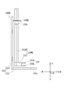
- FIG. 4 The cleaning tool stand 100 according to the first embodiment will be described with reference to FIGS. 1 to 5.
- a description will be given by defining a front-rear direction, a left-right direction, a vertical direction, an X-axis, a Y-axis, and a Z-axis. That is, the side on which the mounting surface is formed on the bottom surface of the main body of the cleaning tool stand is referred to as “lower”, the opposite side is referred to as “upper”, and the axis along the vertical direction is defined as the Z axis.
- the direction in which the bottom surface and the back surface of the cleaning tool stand are connected to each other is referred to as “rear”, and the opposite side is referred to as “front”.
- the X axis Let it be the X axis.
- the right hand side in the state facing the rear side is “right”, the left hand side in the state facing the rear side is “left”, and the axis along the left-right direction is the Y axis.
- the cleaning tool stand 100 is a stand on which a cleaning tool used for cleaning a toilet installed in a toilet or the like is placed. Therefore, first, an example of the cleaning tool placed on the cleaning tool stand 100 will be described, and then the cleaning tool stand 100 according to the present embodiment will be described.
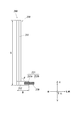
- the cleaning tool 200 is used for cleaning a toilet installed in a toilet and the like, and as shown in FIGS. 1 and 2, a handle 210 gripped by a user of the cleaning tool 200 and attached to the handle 210. And a head section 220 that is provided.
- the handle portion 210 includes a grip portion 211 which is a portion to be gripped by a user of the cleaning tool 200, and a distal end portion 212 connected to the grip portion 211 and provided with an attachment portion 213 for detachably attaching the head portion 220.
- any material can be used as long as it has a strength capable of performing cleaning by attaching the head portion 2 to the attachment portion 213.
- an ABS resin acrylonitrile / butadiene / styrene copolymer
- Resin acrylonitrile / butadiene / styrene copolymer
- Resin acrylonitrile / butadiene / styrene copolymer
- PP polypropylene
- PE polyethylene
- POM polyacetal
- CNF cellulose nanofiber
- the grip part 211 is a part that the user of the cleaning tool 200 grips, and is formed in a rod shape having a longer length than the tip part 212 as shown in FIGS. 1 and 2.
- the grip portion 211 is formed in a linear rod shape having no curved portion in the length direction (the Z-axis direction in FIGS. 1 and 2).
- the “straight line having no curved portion” means that the central axis (the axis along the Z axis in FIGS. 1 and 2) of the rod-shaped grip portion 211 is a straight line, It includes those having irregularities and distortion.
- the length of the grip part 211 is preferably 300 mm to 650 mm in the Z-axis direction, and more preferably 340 mm to 450 mm.
- the length of the grip portion 211 refers to the length from the end opposite to the end connected to the tip 212 to the lowermost portion of the end connected to the end 212.
- the grip portion 211 has a circular cross section (a cross section along the XY plane in FIGS. 1 and 2) and is formed in a columnar shape as a whole.
- the diameter of the cross section is preferably from 10 mm to 40 mm, more preferably from 15 mm to 30 mm.
- the cross-sectional shape is not limited to a circle, and may be, for example, a square, a triangle, an ellipse, or the like.
- the tip part 212 is a part to which the head part 2 of the handle part 1 is attached, as shown in FIG. 1, is formed in a rod shape having a shorter length than the grip part 211, and one end is connected to the grip part 211. And a mounting portion 213 for mounting the head portion 220 at the other end.
- the distal end portion 212 is preferably formed in a linear rod shape having no portion curved in the length direction (the X-axis direction in FIGS. 1 and 2).
- the “straight line having no curved portion” also means that the central axis (the axis along the X axis in FIGS. 1 and 2) of the rod-shaped tip portion 212 is a straight line. It includes those having irregularities and distortion.
- the length of the distal end portion 212 is preferably 70 mm or less in the X-axis direction, and more preferably 40 mm or less.
- the length of the distal end portion 212 refers to the length of the end portion on the side connected to the grip portion 211 from the end portion (the distal end of the mounting portion 213) opposite to the end portion connected to the grip portion 211. It indicates the length (B in FIG. 2) up to the portion located at the rearmost position in FIGS.
- the cross-sectional shape (the cross-sectional shape along the YZ plane in FIGS. 1 and 2) of the distal end portion 212 is a square shape, and it is desirable that the whole except for the mounting portion 213 is formed in a substantially quadrangular prism shape.
- the length of one side of the cross section is preferably from 20 mm to 40 mm, and more preferably from 20 mm to 35 mm.
- the cross-sectional shape is not limited to a square, and may be, for example, a rectangle, a triangle, a circle, an ellipse, or the like.
- the attachment portion 213 is a portion formed at an end of the tip portion 212 opposite to the end connected to the grip portion 211 for detachably attaching the head portion 220 to the handle portion 210. As shown in FIG. 2, a first extension portion 213a and a second extension portion 213b extending in the same direction at predetermined intervals are provided.
- the first extension portion 213 a is located above an end portion (a front end portion in FIGS. 1 and 2) of the tip portion 212 opposite to the side connected to the grip portion 211.
- the formed portion protrudes in a plate shape in the longitudinal direction of the distal end portion 212.
- the second extension portion 213 b is located below an end portion (a front end portion in FIGS. 1 and 2) of the distal end portion 212 opposite to the side connected to the grip portion 211.
- a plate-like portion protruding in the longitudinal direction of the distal end portion 212.
- Both the first extension 213a and the second extension 213b are formed such that the length in the X-axis direction is preferably 35 mm or less, more preferably 30 mm or less.
- the distance between the first extension 213a and the second extension 213b is preferably 3 mm to 20 mm, more preferably 5 mm to 18 mm.
- the interval between the first extension portion 213a and the second extension portion 213b is made slightly smaller than the thickness of the head portion 2 to be used, and the first extension portion 213a and the second extension portion are compressed while the head portion 220 is compressed.
- the head portion 220 can be fixed to the handle portion 210 as shown in FIGS. 1 and 2 by being sandwiched between the handle portion 213b.
- the mounting portion 213 includes a concave portion that is concave upward, at the center of the first extension portion 213a in the Y direction, and the central portion of the second extension portion 213b in the Y direction.
- the head unit 220 can be attached in a curved state so that both ends in the Y-axis direction are close to each other, and the strength of the head unit 220 at the time of cleaning can be improved.
- first extending portion 213a is provided with a downwardly convex portion at the center in the Y direction
- second extending portion 213b is provided with a downwardly convex portion at the center in the Y direction. May be provided.
- connection angles (Relationship between gripper and tip) As shown in FIGS. 1 and 2, the grip 211 and the distal end 212 are connected at one end of the grip 211 and one end of the distal end 212 where the attachment 213 is not provided. It is preferable that these connection angles (the angle ⁇ in FIG. 1) are formed so as to be larger than 45 ° and smaller than 135 °. With this angle, it is easy to clean the lower surface side of the edge of the toilet and its vicinity. Most preferably, these connection angles are formed to be approximately 90 °, and the handle 210 is formed to be L-shaped when viewed from the Y direction.
- the ratio of the length of the grip portion 211 to the tip portion 212 is such that when the length of the grip portion 211 is A in FIG. 1 and the length of the tip portion 212 is B in FIG. Assuming that (A + B) is 100%, it is preferable that the length A of the grip portion 211 is 85% ⁇ A ⁇ 100%, and the length of the distal end portion 212 is 0% ⁇ B ⁇ 15%.
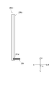
- the entire handle portion 210A is formed to be linear, as in the cleaning tool 200A shown in FIG. 3, and then the side surface (the front side in FIG. 3). ) Is provided with a mounting portion 213A for attaching the head portion 220 so as to protrude from the side surface of the handle portion 210A.
- the attachment portion 213A is formed as a groove provided on the side surface of the handle portion 210A and having a width equal to the interval between the first extension portion 213a and the second extension portion 213b of the attachment portion 213 in the Z direction.
- the head portion 220 is detachably attached to the handle portion 1 by the attachment portion 213 or 213A, and is pressed against a surface to be cleaned such as the inner surface of the toilet to clean the toilet. It is a member.
- any one may be used as long as it can be used by being attached to the handle part 210 by the attachment part 213 or 213A and can be used for cleaning a surface to be cleaned such as a toilet bowl, but is formed of a material having water dissolving property. After the cleaning, it is preferable that the handle 210 can be detached from the attachment portion 213 or 213A and flow into the toilet.
- the head section 220 is formed of a laminated body in which two or more layers are overlapped by folding a single sheet having water dissolvability. By folding one sheet body to form the head section 2, the manufacture thereof can be facilitated. Note that, although the ease of manufacture is reduced, a stacked body may be formed by stacking a plurality of sheet bodies. Further, a stacked body may be formed by stacking a plurality of sheet bodies and further folding the stacked body. By thus forming the head portion 220 as a laminated body, it is possible to easily loosen water when flowing into the toilet.
- the water-disintegrable sheet used for the head section 220 for example, a water-disintegrated paper made by a wet papermaking method, an air-laid nonwoven fabric, or the like can be used.
- Virgin pulp is preferably used as a raw material for such a sheet.
- Foreign materials such as resin and lime may be mixed in recycled paper pulp, and this may cause the surface to be cleaned to be easily damaged during cleaning, and may not be able to obtain the desired water dissolving property when washed, and may be easily clogged. Is caused.
- the head portion 2 is preferably formed in a rectangular shape having a long side of 40 mm to 60 mm and a short side of 35 mm to 55 mm in plan view, and is preferably formed to have a thickness of 5 mm to 20 mm. Further, the head portion 2 is preferably attached to the handle portion 1 so as to protrude from the tip of the attachment portion 213 or 213A by 20 mm to 40 mm, and most preferably to be protruded by 30 mm.
- the head section 220 does not necessarily need to be detachable from the handle section 210, and may be configured integrally with the handle section 210.
- the cleaning tool stand 100 (Stand for cleaning tool) Next, the cleaning tool stand 100 will be described. Since the cleaning tool 200 can be discarded by removing the used head section 220 from the handle section 210 as described above, the cleaning tool 200 is attached to the cleaning tool stand 100 as shown in FIG. The case where only the handle 210 of the tool 200 is placed will be described as an example. However, the present invention is not limited to this, and it is also possible to place the cleaning tool 200 with the head unit 220 attached.
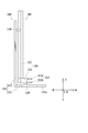
- the cleaning tool stand 100 includes a main body 110, a first support 120, and a second support 130, as shown in FIGS.
- the cleaning tool stand 100 may be made of any material as long as it does not have water absorption and has sufficient strength to mount the cleaning tool. Examples thereof include PP (polypropylene) and PE (polyethylene). , ABS (acrylonitrile-butadiene-styrene copolymer resin) and PET (polyethylene terephthalate).
- the main body 110 includes a bottom part 111 and a rear part 112 connected to the bottom part 111 so as to stand up from the bottom part 111.
- the bottom surface portion 111 is a portion provided on the floor surface or the like provided at the lower portion of the main body portion 110, and is formed such that the lower surface is flat as the mounting surface 111a mounted on the floor surface or the like. It is formed in a plate shape.
- the shape and size of the bottom portion 111 are arbitrary as long as they do not fall when the handle 210 is placed as shown in FIG. 5 or when the cleaning tool 200 is placed, but in plan view, It is preferable that it is 40 mm to 120 mm in the X direction in FIGS. 4 and 5, 55 mm to 110 mm in the Y direction in FIGS. 4 and 5, and 60 mm to 80 mm in the X direction in FIGS.
- FIG. 4 illustrates a case where the bottom surface portion 111 is formed to have a rectangular shape in plan view, but the shape of the bottom surface portion 111 is not limited thereto.
- the rear portion 112 is a portion that stands substantially vertically upward from near the end of the bottom portion 111 in plan view (near the rear end in FIGS. 4 and 5), and preferably has a height in the Z direction. Is formed to have a width of 300 mm to 650 mm, more preferably 340 mm to 450 mm, and a width in the Y direction, preferably 10 mm to 40 mm, and more preferably 15 mm to 30 mm.
- FIG. 4 illustrates the case where the rear surface 112 is formed so as to be entirely rectangular when viewed from the X direction. However, the rear surface 112 may include a second support 130 described below. The specific shape is not limited to this. Note that the angle at which the back portion 112 stands from the bottom portion 111 is not necessarily substantially vertical, and coincides with the connection angle between the grip portion 211 and the tip portion 212 in the handle portion 210 to be placed. It is preferable to be set so that
- the first support portion 120 is a protruding portion formed on the upper surface of the bottom portion 111 of the main body portion 110, that is, on the surface opposite to the mounting surface 111a, and protruding upward. ,
- the specific shape of the first support portion 120 is arbitrary as long as it can support the handle portion 210 from below, but the portion in contact with the handle portion 210, that is, the shape of the upper end portion is the tip of the handle portion 210. Desirably, it is in linear contact with the part 212. In this case, the area of the handle 210 in contact with the first support 120 is reduced, and the handle 210 is more easily dried.
- the first support portion 120 is formed in a triangular prism shape that becomes a triangle when viewed from the Y direction, and as shown in FIG. Is formed so as to be in contact with the lower surface of the tip portion 212 of the handle 210.
- it may be formed in a semicircular column shape with an arc on the upper surface and a chord on the lower surface when viewed from the Y direction.
- the height of the first support portion 120 from the bottom surface portion 111 is preferably 3 mm to 30 mm, and more preferably 5 mm to 20 mm.
- the shape of the upper end of the first support portion 120 as viewed in the X direction matches the shape of the lower surface of the distal end portion 212.
- the first support 120 is also formed so that the upper end is straight when viewed in the X direction.
- the distal end portion 212 of the handle portion 210 is formed in a columnar shape having a circular cross section along the YZ plane, the shape of the upper end portion of the first support portion 120 viewed from the X direction. Is preferably formed to have a curved shape corresponding to this.
- the formation position of the first support portion 120 is not limited to the illustrated position as long as it can support the handle portion 210 from below.
- the second support portion 130 is a protruding portion formed on the side (the front surface in FIGS. 4 and 5) connected to the bottom surface portion 111 of the back surface portion 112 of the main body portion 110. This is a portion for supporting the handle 210 from the horizontal direction (rear in FIGS. 4 and 5).
- the specific shape of the second support portion 130 is arbitrary as long as the handle portion 210 can be supported in the horizontal direction, but the portion in contact with the handle portion 210, that is, the front side in FIGS. It is preferable that the shape matches the shape of the grip 211 of the handle 210. For example, when the grip part 211 is formed in a cylindrical shape as shown in FIG.
- the second support part 130 is also formed such that the front surface has a corresponding curved surface.
- the second support portion 130 is formed so that the front side draws an arc corresponding to the grip portion 211 in plan view, and the short side direction of the rear portion 112 in front view (FIG. In the Y direction), preferably 10 mm to 40 mm, more preferably 15 mm to 30 mm, and preferably 5 mm to 30 mm, more preferably in the longitudinal direction (Z direction in FIG. 4) of the back portion 112 in a front view. It has a length of 8 mm to 20 mm, and at a point where the height from the back surface 112 (X direction in FIG. 4) is the lowest at the center in the Y direction, preferably 5 mm to 20 mm, more preferably 8 mm to 15 mm. It is formed so that it becomes.
- the shape of the front side of the second support part 130 also corresponds to this.
- it is formed in a planar shape or has a depression matching the cross-sectional shape along the XY plane of the grip portion 211 in a plan view, and is formed so that the grip portion 211 can be fitted into the depression.
- the second support portion 130 is configured such that the width in the Z direction becomes narrower toward the front to make the grip portion 211 easier to dry, and the second support portion 130 comes into contact with the handle portion 210 in a linear shape like the first support portion 120. It may be.
- the formation position of the second support portion 130 is not limited to the illustrated position as long as the handle portion 210 can be supported from the rear.
- the handle 210 of the cleaning tool 200 is stored so as not to touch other than the first support 120 and the second support 130. It becomes possible. Thereby, during storage of the handle 210, it can be easily dried and the hygiene can be easily maintained.
- the handle 210 since the handle 210 is supported at two points, the first support 120 and the second support 130, the handle 210 can be stored in a stable state. For example, after a hole is provided in the grip portion 211 of the handle 210, a hook or the like is passed through the hole, and the handle 210 is supported by being stored at a single point. Although the storage can be performed in a state where the inner surface other than the inner surface of the hole is opened, there is a possibility that the handle 210 may swing in such a storage method.
- the cleaning tool 200 is used for cleaning toilet bowls and the like, and the user often dislikes it because of concerns about hygiene. On the other hand, according to the cleaning tool stand 100 according to the present embodiment, such a fear does not occur.
- the handle 210 Since the handle 210 has a simple structure that is only supported at two points, the first support 120 and the second support 130, the handle 210 can be easily stored and taken out.
- FIG. 5 illustrates the case where the head part 220 is removed and only the handle part 210 is stored.
- the cleaning tool 200 with the head 220 is kept as it is, or when the cleaning tool from which the head cannot be removed is stored, the same effect as when only the handle 210 is stored can be obtained.
- the entire cleaning tool including the head portion is supported by the first support portion 120 and the second support portion 130, and is stored so as not to touch other than the first support portion 120 and the second support portion 130. Therefore, the entire cleaning tool can be easily dried.
- the cleaning tool 200 can be stored in a stable state, and the cleaning tool 200 can be stored and removed. Also becomes easier.
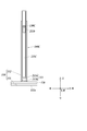
- a cleaning tool stand 100A according to the second embodiment will be described with reference to FIGS.
- the same parts as those of the cleaning tool stand 100 according to the first embodiment are denoted by the same reference numerals, and description thereof will be omitted.
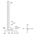
- the cleaning tool stand 100 ⁇ / b> A has the first support portion 120 and the second support portion 130 ⁇ / b> A both formed on the upper surface of the bottom portion 111.
- the main body 110A does not have the rear surface 112.
- Other configurations are the same as those of the cleaning tool stand 100 according to the first embodiment.
- the second support 130A is formed to be the same height as the first support 120 in the Z direction. Further, like the first support part 120, it is desirable that the tip part 212 linearly contacts the tip part 212 of the handle part 210. In this case, the area of the handle 210 in contact with the second support 130A is reduced, and the handle 210 is more easily dried.
- the second support 130A may have the same shape and size as the first support 120. Therefore, for example, it is formed in a triangular prism shape having a triangular shape as viewed from the Y direction shown in FIGS. 6 and 7, or a semicircular column shape having an arc on the upper surface and a chord on the lower surface as viewed in the Y direction. Is preferred.
- the main body 110A is the same as the cleaning tool stand 100 according to the first embodiment, except that the main body 110A does not have the back surface 112 and is configured only of the bottom surface 111. Although the effect of reducing the size of a main body described later cannot be obtained, a main body having a back surface 112 similar to that of the first embodiment can also be used.
- the main body portion is made compact, and the handle portion 210 is supported by the first support portion 120 and the second support portion 130A as shown in FIG.
- the same effects as in the first embodiment can be obtained.
- the cleaning tool 200 with the head part 220 attached as it is, or when storing a cleaning tool from which the head part cannot be removed the same effect as when only the handle part 210 is stored can be obtained.
- the points that can be obtained are the same as in the first embodiment.
- a cleaning tool stand 100B according to the third embodiment will be described with reference to FIGS.
- the same parts as those of the cleaning tool stand 100 according to the first embodiment are denoted by the same reference numerals, and description thereof will be omitted.
- the grip portion 211B of the handle 210B is provided with two concave portions 211a and 211a. Used.
- the handle 210B is the same as the handle 210 shown in FIGS. 1, 2 and the like, except that the handle 210B includes recesses 211a, 211a.
- the recesses 211 a and 211 a have an angle of approximately 90 degrees from the direction (the front in FIGS. 8 and 9) of the gripping portion 211 ⁇ / b> B facing the side where the mounting portion 213 is provided at the distal end portion 212.
- These concave portions are provided in two opposing directions (left and right in FIGS. 8 and 9).
- the recesses 211a, 211a are provided at positions where the grips 211B have the same height in the Z direction so as to penetrate the grips 211B in the X direction when viewed from the X direction. I have. Further, the recesses 211a, 211a need to have a size that allows the first support 120B and the second support 130B of the cleaning tool stand 100B to be described later to pass in the X direction.
- the cleaning tool stand 100 ⁇ / b> B includes a first support portion 120 ⁇ / b> B and a second support portion 130 ⁇ / b> B both provided on the rear surface portion 112.
- the rear surface 112 is formed so as to stand substantially vertically upward from the bottom surface 111.
- Other configurations are the same as those of the cleaning tool stand 100 according to the first embodiment.
- the first support portion 120B and the second support portion 130B are formed at positions at the same height in the Z direction on the back surface portion 112 so as to protrude forward with a certain interval in the Y direction.
- the distance between the first support portion 120B and the second support portion 130B is the width in the Y direction of the portion where the concave portions 211a and 211a are formed in the grip portion 211B of the handle portion 210B. And is wider than this, and is formed to be narrower than the width immediately above the portion where the depressions 211a, 211a in the grip portion 211B are formed.
- Each of these is smaller than the recesses 211a, 211a in the Z direction, and is formed so as to be able to pass through the recesses 211a, 211a.
- a specific shape for example, it can be formed in a columnar shape as shown in FIG. 8 or any other shape as long as it can pass through the recessed portion 211a.
- first support portion 120B and the second support portion 130B are arranged such that the distance from the bottom surface 111 to the upper end thereof is from the upper end of the recessed portion 211a of the handle 210B to the lower end of the handle 210B.
- first support portion 120B and the second support portion 130B are passed through the recessed portions 211a, 211a, as shown in FIG. 8 and FIG. It is formed such that a gap is formed between the component stand 100B and the bottom surface 111.
- the handle 210B can be supported by passing the first support 120B and the second support 130B through the recesses 211a and 211a of the grip 211B.
- the same effects as in the first embodiment can be obtained.
- the same effect as when only the handle part 210 is stored can be obtained.
- the points that can be obtained are the same as in the first embodiment.
- a cleaning tool stand 100C according to a fourth embodiment will be described with reference to FIGS.
- the same parts as those of the cleaning tool stand 100 according to the first embodiment are denoted by the same reference numerals, and description thereof will be omitted.
- a cleaning tool in which a grip 211C of a handle 210C is formed with a hole 211b penetrating therethrough used.
- the handle 210C is the same as the handle 210 shown in FIGS. 1, 2 and the like, except that the handle 211C includes a hole 211b.
- the hole 211b is a hole formed so as to penetrate the grip 211C in the same direction as the extending direction of the distal end portion 212 (the X direction in FIGS. 10 and 11). .
- the hole portion 211b may have any specific shape as long as it is formed so as to penetrate the grip portion 211C in the X direction, but the second support portion 130C formed on the cleaning tool stand 100C described below is not required. It is necessary to have a size that can be inserted.
- the cleaning tool stand 100C is configured such that the second support portion provided on the rear surface portion 112 is a second support portion 130C that protrudes forward in a columnar shape.
- Other configurations are the same as those of the cleaning tool stand 100 according to the first embodiment.
- the second support portion 130 ⁇ / b> C is a protruding portion formed on the side (the front surface in FIGS. 10 and 11) of the back surface portion 112 connected to the bottom surface portion 111. When viewed from the direction, it is formed to have a size and a shape that can be inserted into the hole 211b formed in the handle 210C.
- the second support portion 130 ⁇ / b> C is formed in a columnar shape is illustrated.
- the second support portion 130 ⁇ / b> C may be formed in another columnar shape such as a triangular prism, a quadrangular prism, or the like. It is not limited to this.
- the second support 130C is in a state where the first support 120 and the tip 212 are in contact with the second support 130C inserted through the hole 211b. It is formed so that it becomes.
- the distance from the bottom surface 111 to the second support 130C becomes smaller than that of the first support 120. Even when the distance in which the height in the Z direction and the length from the lower end of the handle 210C to the hole 211b are not exactly the same, the first support 120 and the tip 212 are in contact with each other. it can.
- the distal end 212 of the handle 210C is supported by the first support 120, and the grip 211C of the handle 210C is supported by the second support 130C.
- the same effect as in the first embodiment can be obtained.
- the handle portion 210C can be further stored in a stable state.
- the cleaning tool 200 with the head part 220 attached as it is, or when storing a cleaning tool from which the head part cannot be removed the same effect as when only the handle part 210 is stored can be obtained.
- the points that can be obtained are the same as in the first embodiment.
- the cleaning tool stand may include a storage unit that stores the replacement head unit 220 before use.
- a storage unit that stores the replacement head unit 220 before use.
- a storage section 140 is provided at the end (the front end in FIG. 12).
- the storage section 140 is formed in a shelf shape having a plurality of storage spaces 141, and each storage space 141 has a size capable of storing the head section 220. Further, it is desirable that the lowermost storage space 141 is also formed at a position higher than the upper surface side of the bottom surface portion 111. Thus, it is possible to prevent the replacement head unit 220 from being wet by the moisture of the handle 210 after use.
- the present invention can be suitably used in the field of manufacturing a stand for a cleaning tool.
Landscapes
- Health & Medical Sciences (AREA)
- Public Health (AREA)
- Non-Flushing Toilets (AREA)
- Cleaning Implements For Floors, Carpets, Furniture, Walls, And The Like (AREA)
Abstract
清掃対象物にヘッド部220を押し付けて清掃する清掃具200又は清掃具200の柄部210を保管対象物とする清掃具用スタンド100であって、床面等に載置される載置面111aを有する本体部110と、本体部110に備えられ、前記保管対象物を支持する第一支持部120及び第二支持部130を備え、第一支持部120及び第二支持部130は、前記保管対象物が本体部110に接しない状態で、前記保管対象物を支持する。これによって、保管時に清掃具を乾燥させ易い清掃具用スタンドを提供することができる。
Description
本発明は、清掃具用スタンドに関する。
従来、トイレに設置された便器の清掃に用いられるクリーニングブラシ等の清掃具が普及している。このような清掃具は、使用者が柄を持ち、ヘッド部により便器の内面を擦って汚れを落とすように使用されるが、清潔性への不安から、不使用時には、その保管のために専用のスタンドが用いられる(例えば、特許文献1参照)。
このような清掃具用スタンドにおいては、衛生性を保つため、清掃時に濡れることとなる清掃具の先端付近が覆われることなく、乾燥し易い状態で保管されることが望ましい。
しかし、特許文献1に記載の清掃具用スタンドにおいては、清掃具の先端付近が容器内に収納されることから、これが乾燥し難かった。
しかし、特許文献1に記載の清掃具用スタンドにおいては、清掃具の先端付近が容器内に収納されることから、これが乾燥し難かった。
本発明の課題は、保管時に清掃具を乾燥させ易い清掃具用スタンドを提供することである。
上記課題を解決するために、請求項1に記載の発明は、
清掃対象物にヘッド部を押し付けて清掃する清掃具又は当該清掃具の柄部を保管対象物とする清掃具用スタンドであって、
床面等に載置される載置面を有する本体部と、
前記本体部に備えられ、前記保管対象物を支持する第一支持部及び第二支持部と、を備え、
前記第一支持部及び前記第二支持部は、前記保管対象物が前記本体部に接しない状態で、前記保管対象物を支持することを特徴とする。
本発明によれば、保管時に清掃具を乾燥させ易い清掃具用スタンドを提供することができる。
清掃対象物にヘッド部を押し付けて清掃する清掃具又は当該清掃具の柄部を保管対象物とする清掃具用スタンドであって、
床面等に載置される載置面を有する本体部と、
前記本体部に備えられ、前記保管対象物を支持する第一支持部及び第二支持部と、を備え、
前記第一支持部及び前記第二支持部は、前記保管対象物が前記本体部に接しない状態で、前記保管対象物を支持することを特徴とする。
本発明によれば、保管時に清掃具を乾燥させ易い清掃具用スタンドを提供することができる。
請求項2に記載の発明は、請求項1に記載の清掃具用スタンドであって、
前記本体部は、前記載置面が形成された底面部と、前記底面部から立設する背面部と、を備え、
前記第一支持部は前記底面部に備えられ、前記第二支持部は前記背面部に備えられていることを特徴とする。
本発明によれば、保管時に清掃具を乾燥させ易い清掃具用スタンドを提供することができる。
前記本体部は、前記載置面が形成された底面部と、前記底面部から立設する背面部と、を備え、
前記第一支持部は前記底面部に備えられ、前記第二支持部は前記背面部に備えられていることを特徴とする。
本発明によれば、保管時に清掃具を乾燥させ易い清掃具用スタンドを提供することができる。
請求項3に記載の発明は、請求項1に記載の清掃具用スタンドであって、
前記本体部は、前記載置面が形成された底面部を備え、
前記第一支持部及び前記第二支持部は、前記底面部に備えられていることを特徴とする。
本発明によれば、保管時に清掃具を乾燥させ易い清掃具用スタンドを提供することができる。
前記本体部は、前記載置面が形成された底面部を備え、
前記第一支持部及び前記第二支持部は、前記底面部に備えられていることを特徴とする。
本発明によれば、保管時に清掃具を乾燥させ易い清掃具用スタンドを提供することができる。
請求項4に記載の発明は、請求項1に記載の清掃具用スタンドであって、
前記本体部は、前記載置面が形成された底面部と、前記底面部から立設する背面部と、を備え、
前記第一支持部及び前記第二支持部は、前記背面部に、同一の高さにおいて、所定の間隔を空けて同一方向へと延出するように備えられていることを特徴とする。
本発明によれば、保管時に清掃具を乾燥させ易い清掃具用スタンドを提供することができる。
前記本体部は、前記載置面が形成された底面部と、前記底面部から立設する背面部と、を備え、
前記第一支持部及び前記第二支持部は、前記背面部に、同一の高さにおいて、所定の間隔を空けて同一方向へと延出するように備えられていることを特徴とする。
本発明によれば、保管時に清掃具を乾燥させ易い清掃具用スタンドを提供することができる。
請求項5に記載の発明は、請求項2に記載の清掃具用スタンドであって、
前記第二支持部は、水平方向へと突出する柱状に形成されていることを特徴とする。
本発明によれば、保管時に清掃具を乾燥させ易い清掃具用スタンドを提供することができる。
前記第二支持部は、水平方向へと突出する柱状に形成されていることを特徴とする。
本発明によれば、保管時に清掃具を乾燥させ易い清掃具用スタンドを提供することができる。
請求項6に記載の発明は、請求項1から5のいずれか一項に記載の清掃具用スタンドであって、
前記清掃具は、前記柄部と前記ヘッド部とが着脱自在に形成され、
前記本体部に、前記ヘッド部を収納する収納部を備えることを特徴とする。
本発明によれば、柄部に取り付けられていないヘッド部の保管が容易となる。
前記清掃具は、前記柄部と前記ヘッド部とが着脱自在に形成され、
前記本体部に、前記ヘッド部を収納する収納部を備えることを特徴とする。
本発明によれば、柄部に取り付けられていないヘッド部の保管が容易となる。
本発明によれば、保管時に清掃具を乾燥させ易い清掃具用スタンドを提供することができる。
以下、本発明の実施形態である清掃具用スタンドの具体的な態様について、図1から図12に基づいて説明する。ただし、本発明の技術的範囲は、図示例に限定されない。
[第一実施形態]
第一実施形態に係る清掃具用スタンド100について、図1から図5に基づいて説明する。なお、以下においては、図4に示すように、前後方向、左右方向及び上下方向並びにX軸、Y軸及びZ軸を定めて説明する。すなわち、清掃具用スタンドの本体部の底面部に載置面が形成された側を「下」、その反対側を「上」とし、上下方向に沿った軸をZ軸とする。また、Z軸方向から見て、清掃具用スタンドの本体部の底面部と背面部とが接続されている方向を「後」、その反対側を「前」とし、前後方向に沿った軸をX軸とする。また、後側を向いた状態における右手側を「右」、後側を向いた状態における左手側を「左」とし、左右方向に沿った軸をY軸とする。
第一実施形態に係る清掃具用スタンド100について、図1から図5に基づいて説明する。なお、以下においては、図4に示すように、前後方向、左右方向及び上下方向並びにX軸、Y軸及びZ軸を定めて説明する。すなわち、清掃具用スタンドの本体部の底面部に載置面が形成された側を「下」、その反対側を「上」とし、上下方向に沿った軸をZ軸とする。また、Z軸方向から見て、清掃具用スタンドの本体部の底面部と背面部とが接続されている方向を「後」、その反対側を「前」とし、前後方向に沿った軸をX軸とする。また、後側を向いた状態における右手側を「右」、後側を向いた状態における左手側を「左」とし、左右方向に沿った軸をY軸とする。
{実施形態の構成}
清掃具用スタンド100は、トイレに設置された便器の清掃等に用いられる清掃具を載置するためのスタンドである。したがって、まず、清掃具用スタンド100に載置される清掃具の一例について説明し、続いて本実施形態に係る清掃具用スタンド100について説明する。
清掃具用スタンド100は、トイレに設置された便器の清掃等に用いられる清掃具を載置するためのスタンドである。したがって、まず、清掃具用スタンド100に載置される清掃具の一例について説明し、続いて本実施形態に係る清掃具用スタンド100について説明する。
(清掃具)
清掃具200は、トイレに設置された便器の清掃などに用いられるものであり、図1及び図2に示すように、清掃具200の使用者が把持する柄部210と、柄部210に取り付けられるヘッド部220と、から構成される。
清掃具200は、トイレに設置された便器の清掃などに用いられるものであり、図1及び図2に示すように、清掃具200の使用者が把持する柄部210と、柄部210に取り付けられるヘッド部220と、から構成される。
(柄部)
柄部210は、清掃具200の使用者が把持する部分である把持部211と、把持部211と接続され、ヘッド部220を着脱自在に取り付ける取付部213が備えられた先端部212と、から構成される。
柄部210を形成する材料としては、取付部213にヘッド部2を取り付けて清掃を行うことができる強度を有するものであれば任意であるが、例えば、ABS樹脂(アクリロニトリル・ブタジエン・スチレン共重合樹脂)、PP(ポリプロピレン)、PE(ポリエチレン)、POM(ポリアセタール)、CNF(セルロースナノファイバー)、木材、金属等を用いることができる。
柄部210は、清掃具200の使用者が把持する部分である把持部211と、把持部211と接続され、ヘッド部220を着脱自在に取り付ける取付部213が備えられた先端部212と、から構成される。
柄部210を形成する材料としては、取付部213にヘッド部2を取り付けて清掃を行うことができる強度を有するものであれば任意であるが、例えば、ABS樹脂(アクリロニトリル・ブタジエン・スチレン共重合樹脂)、PP(ポリプロピレン)、PE(ポリエチレン)、POM(ポリアセタール)、CNF(セルロースナノファイバー)、木材、金属等を用いることができる。
(把持部)
把持部211は、清掃具200の使用者が把持する部分であり、図1及び図2に示すように、先端部212と比較して長さの長い棒状に形成される。
把持部211は、清掃具200の使用者が把持する部分であり、図1及び図2に示すように、先端部212と比較して長さの長い棒状に形成される。
把持部211は、長さ方向(図1及び図2におけるZ軸方向)において、湾曲した部分を有しない直線状の棒状に形成されることが好ましい。なお、ここで「湾曲した部分を有しない直線状」とは、棒状の把持部211の中心軸(図1及び図2においてはZ軸に沿った軸)が直線であることをいい、表面に凹凸や歪みを有するものを含むものとする。
把持部211の長さは、Z軸方向に300mmから650mmであることが好ましく、340mmから450mmであることがさらに好ましい。ここで把持部211の長さとは、先端部212と接続されているのと反対側の端部から、先端部212と接続されている側の端部のうち、最も下方に位置する部分までの長さ(図2におけるA)を指す。
また、使用者が把持し易くするため、把持部211の断面形状(図1及び図2におけるXY面に沿った断面おける形状)は円形であり、全体が円柱状に形成されることが望ましい。また、断面の直径が10mmから40mmであることが好ましく、15mmから30mmであることがさらに好ましい。ただし、断面形状は円形に限定されず、例えば四角形、三角形、楕円形等であってもよい。
把持部211の長さは、Z軸方向に300mmから650mmであることが好ましく、340mmから450mmであることがさらに好ましい。ここで把持部211の長さとは、先端部212と接続されているのと反対側の端部から、先端部212と接続されている側の端部のうち、最も下方に位置する部分までの長さ(図2におけるA)を指す。
また、使用者が把持し易くするため、把持部211の断面形状(図1及び図2におけるXY面に沿った断面おける形状)は円形であり、全体が円柱状に形成されることが望ましい。また、断面の直径が10mmから40mmであることが好ましく、15mmから30mmであることがさらに好ましい。ただし、断面形状は円形に限定されず、例えば四角形、三角形、楕円形等であってもよい。
(先端部)
先端部212は、柄部1のヘッド部2が取り付けられる部分であり、図1に示すように、把持部211と比較して長さの短い棒状に形成され、一端部が把持部211と接続され、他端部にヘッド部220を取り付ける取付部213を備える。
先端部212は、柄部1のヘッド部2が取り付けられる部分であり、図1に示すように、把持部211と比較して長さの短い棒状に形成され、一端部が把持部211と接続され、他端部にヘッド部220を取り付ける取付部213を備える。
先端部212は、長さ方向(図1及び図2におけるX軸方向)に湾曲した部分を有しない直線状の棒状に形成されることが好ましい。なお、ここでも「湾曲した部分を有しない直線状」とは、棒状の先端部212の中心軸(図1及び図2においてはX軸に沿った軸)が直線であることをいい、表面に凹凸や歪みを有するものを含むものとする。
先端部212の長さは、X軸方向に70mm以下であることが好ましく、40mm以下であることがさらに好ましい。ここで、先端部212の長さとは、把持部211と接続されているのと反対側の端部(取付部213の先端)から、把持部211と接続されている側の端部のうち、最も図1及び図2における後方に位置する部分までの長さ(図2におけるB)を指す。
また、先端部212の断面形状(図1及び図2におけるYZ面に沿った断面における形状)は正方形状であり、取付部213を除いて全体が略四角柱状に形成されることが望ましい。また、断面の一辺の長さが20mmから40mmであることが好ましく、20mmから35mmであることがさらに好ましい。ただし、断面形状は正方形に限定されず、例えば矩形、三角形、円形、楕円形等であってもよい。
先端部212の長さは、X軸方向に70mm以下であることが好ましく、40mm以下であることがさらに好ましい。ここで、先端部212の長さとは、把持部211と接続されているのと反対側の端部(取付部213の先端)から、把持部211と接続されている側の端部のうち、最も図1及び図2における後方に位置する部分までの長さ(図2におけるB)を指す。
また、先端部212の断面形状(図1及び図2におけるYZ面に沿った断面における形状)は正方形状であり、取付部213を除いて全体が略四角柱状に形成されることが望ましい。また、断面の一辺の長さが20mmから40mmであることが好ましく、20mmから35mmであることがさらに好ましい。ただし、断面形状は正方形に限定されず、例えば矩形、三角形、円形、楕円形等であってもよい。
(取付部)
取付部213は、先端部212の把持部211に接続されているのと反対側の端部に形成された、柄部210にヘッド部220を着脱自在に取り付けるための部分であり、図1及び図2に示すように、所定の間隔を空けて同一方向へと延出する第一延出部213aと、第二延出部213bと、を備える。
取付部213は、先端部212の把持部211に接続されているのと反対側の端部に形成された、柄部210にヘッド部220を着脱自在に取り付けるための部分であり、図1及び図2に示すように、所定の間隔を空けて同一方向へと延出する第一延出部213aと、第二延出部213bと、を備える。
第一延出部213aは、図1及び図2に示すように、先端部212の把持部211と接続されている側と反対側の端部(図1及び図2における前端部)の上側に形成された、先端部212の長さ方向へと板状に突出する部分である。
第二延出部213bは、図1及び図2に示すように、先端部212の把持部211と接続されている側と反対側の端部(図1及び図2における前端部)の下側に形成された、先端部212の長さ方向へと板状に突出する部分である。
第二延出部213bは、図1及び図2に示すように、先端部212の把持部211と接続されている側と反対側の端部(図1及び図2における前端部)の下側に形成された、先端部212の長さ方向へと板状に突出する部分である。
第一延出部213a及び第二延出部213bは、共にX軸方向の長さが、好ましくは35mm以下、さらに好ましくは30mm以下となるように形成される。
また、第一延出部213aと第二延出部213bとの間隔は、3mmから20mmであることが好ましく、5mmから18mmであることがさらに好ましい。
また、第一延出部213aと第二延出部213bとの間隔は、3mmから20mmであることが好ましく、5mmから18mmであることがさらに好ましい。
第一延出部213a及び第二延出部213bの間隔を、使用するヘッド部2の厚みよりも僅かに狭くし、ヘッド部220を圧縮しつつ第一延出部213aと、第二延出部213bとの間に挟み込むようにすることで、図1及び図2に示すようにヘッド部220を柄部210に対して固定することができる。
なお、図示していないが、取付部213は、第一延出部213aのY方向における中央部に、上方向へと凹状となる凹部を備え、第二延出部213bのY方向における中央部に、上方向へと凸状となる凸部を備えることが好ましい。この場合、ヘッド部220をY軸方向の両端部同士が近づくように湾曲した状態で取り付けることが可能となり、清掃時のヘッド部220の強度を向上させることができる。なお、反対に第一延出部213aのY方向における中央部に、下方向へと凸状となる凸部を備え、第二延出部213bのY方向における中央部に、下方向へと凹状となる凹部を備えてもよい。
(把持部と先端部の関係)
把持部211と先端部212とは、図1及び図2に示すように、把持部211の一端部と、先端部212の取付部213が備えられていない一端部とにおいて接続されているが、これらの接続角度(図1における角θ)が、45°より大きく、135°より小さくなるように形成されることが好ましい。この角度であれば、便器の縁部の下面側やその近傍の清掃を行い易くなる。また、これらの接続角度が、略90°となるように形成され、柄部210が、Y方向から見てL字型となるように形成されていることが最も好ましい。
把持部211と先端部212とは、図1及び図2に示すように、把持部211の一端部と、先端部212の取付部213が備えられていない一端部とにおいて接続されているが、これらの接続角度(図1における角θ)が、45°より大きく、135°より小さくなるように形成されることが好ましい。この角度であれば、便器の縁部の下面側やその近傍の清掃を行い易くなる。また、これらの接続角度が、略90°となるように形成され、柄部210が、Y方向から見てL字型となるように形成されていることが最も好ましい。
また、把持部211と先端部212との長さの比率は、把持部211の長さを図1におけるAとし、先端部212の長さを図1におけるBとした場合に、全体の長さ(A+B)を100%として、把持部211の長さAが、85%<A<100%、先端部212の長さが、0%<B≦15%となることが望ましい。
なお、先端部の長さを短くしていくと、図3に示す清掃具200Aのように、柄部210Aの全体が直線状となるように形成された上で、側面(図3においては前側)に、柄部210Aの側面から突出するようにヘッド部220を取り付ける取付部213Aが備えられた状態となる。この場合、取付部213Aは、柄部210Aの側面に備えられた、Z方向において取付部213における第一延出部213aと第二延出部213bとの間隔と等しい幅となる溝として形成することができる
(ヘッド部)
ヘッド部220は、図1から図3に示すように、取付部213又は213Aによって柄部1に着脱自在に取り付けられて、便器の内面などの被清掃面に押し付けられてその清掃を行うための部材である。
ヘッド部220は、図1から図3に示すように、取付部213又は213Aによって柄部1に着脱自在に取り付けられて、便器の内面などの被清掃面に押し付けられてその清掃を行うための部材である。
ヘッド部220としては、取付部213又は213Aによって柄部210に取り付けて使用され、便器等の被清掃面の清掃に用いることができるものであれば任意であるが、水解性を有する素材により形成され、清掃後、柄部210の取付部213又は213Aから外して便器に流すことが可能であることが好ましい。
具体的には、例えばヘッド部220は、水解性を有する一枚のシート体を折り畳むことで2層以上重ね合わされた積層体により形成される。一枚のシート体を折り畳んでヘッド部2を形成することで、その製造を容易にすることができる。
なお、製造の容易性は低下するものの、複数枚のシート体を重ね合わせることで積層体が形成されていてもよい。また、複数枚のシート体を重ね合わせた上で、これをさらに折り畳むことによって、積層体が形成されていてもよい。
このようにヘッド部220を積層体とすることで、便器に流す際に水に対してほぐれやすくすることができる。
なお、製造の容易性は低下するものの、複数枚のシート体を重ね合わせることで積層体が形成されていてもよい。また、複数枚のシート体を重ね合わせた上で、これをさらに折り畳むことによって、積層体が形成されていてもよい。
このようにヘッド部220を積層体とすることで、便器に流す際に水に対してほぐれやすくすることができる。
また、ヘッド部220に用いられる水解性を有するシート体としては、例えば、湿式抄紙法により作製される水解紙や、エアレイド不織布などを用いることができる。このようなシート体の原料には、バージンパルプが用いられることが好ましい。古紙再生パルプには樹脂や石灰等の異物が混入することがあり、これによって、清掃時に被清掃面に傷がつき易くなる、流した際に所望の水解性が得られず詰まり易くなるといったリスクが生じるためである。
ヘッド部2は、平面視において長辺40mmから60mm、短辺35mmから55mmの長方形状に形成され、厚みが5mmから20mmとなるように形成されることが好ましい。
また、ヘッド部2は、柄部1に対し、取付部213又は213Aの先端から、20mmから40mm突出するように取り付けられることが好ましく、30mm突出するように取り付けられることが最も好ましい。
また、ヘッド部2は、柄部1に対し、取付部213又は213Aの先端から、20mmから40mm突出するように取り付けられることが好ましく、30mm突出するように取り付けられることが最も好ましい。
なお、ヘッド部220は、必ずしも柄部210に対して着脱自在であることを要せず、柄部210と一体として構成されていてもよい。
(清掃具用スタンド)
次に清掃具用スタンド100について説明する。なお、上記のように清掃具200は、使用後のヘッド部220を柄部210から外して破棄できるものであることから、以下においては、図5に示すように清掃具用スタンド100に、清掃具200の柄部210のみを載置する場合を例として説明する。ただし、これに限られず、ヘッド部220が付いた状態の清掃具200を載置することも可能である。
次に清掃具用スタンド100について説明する。なお、上記のように清掃具200は、使用後のヘッド部220を柄部210から外して破棄できるものであることから、以下においては、図5に示すように清掃具用スタンド100に、清掃具200の柄部210のみを載置する場合を例として説明する。ただし、これに限られず、ヘッド部220が付いた状態の清掃具200を載置することも可能である。
清掃具用スタンド100は、図4及び図5に示すように、本体部110と、第一支持部120と、第二支持部130と、を備える。清掃具用スタンド100の材料は、吸水性を有せず、かつ、清掃具を載置することができる強度を有するものであれば任意であるが、例えば、PP(ポリプロピレン)、PE(ポリエチレン)、ABS(アクリロニトリル・ブタジエン・スチレン共重合樹脂)、PET(ポリエチレンテレフタレート)等の材料を用いて形成される。
(本体部)
本体部110は、図4及び図5に示すように、底面部111と、底面部111から立設するように底面部111と接続された背面部112とからなる。
本体部110は、図4及び図5に示すように、底面部111と、底面部111から立設するように底面部111と接続された背面部112とからなる。
(底面部)
底面部111は、本体部110の下部に備えられた、床面等に載置される部分であり、下面が床面等に載置される載置面111aとして平面となるように形成された板状に形成されている。
底面部111の形状及び大きさは、図5に示すように柄部210を載置した状態、又は清掃具200を載置した状態において転倒しないものであれば任意であるが、平面視において、図4及び図5におけるX方向に40mmから120mm、図4及び図5におけるY方向に55mmから110mmであることが好ましく、図4及び図5におけるX方向に60mmから80mm、図4及び図5におけるY方向に65mmから85mmであることがさらに好ましい。図4においては、底面部111が平面視矩形状となるように形成された場合につき図示したが、底面部111の形状はこれに限られない。
底面部111は、本体部110の下部に備えられた、床面等に載置される部分であり、下面が床面等に載置される載置面111aとして平面となるように形成された板状に形成されている。
底面部111の形状及び大きさは、図5に示すように柄部210を載置した状態、又は清掃具200を載置した状態において転倒しないものであれば任意であるが、平面視において、図4及び図5におけるX方向に40mmから120mm、図4及び図5におけるY方向に55mmから110mmであることが好ましく、図4及び図5におけるX方向に60mmから80mm、図4及び図5におけるY方向に65mmから85mmであることがさらに好ましい。図4においては、底面部111が平面視矩形状となるように形成された場合につき図示したが、底面部111の形状はこれに限られない。
(背面部)
背面部112は、底面部111の平面視における端部付近(図4及び図5においては後端部付近)から略垂直に上方へと立設する部分であり,高さがZ方向に、好ましくは300mmから650mm、さらに好ましくは340mmから450mmとなり、幅がY方向に、好ましくは10mmから40mm、さらに好ましくは15mmから30mmとなるように形成される。
図4においては、背面部112が、X方向から見て、全体が矩形状となるように形成された場合につき図示したが、背面部112は、後述の第二支持部130を備えることができるものであればよく、具体的な形状はこれに限られない。
なお、背面部112が底面部111から立設する角度は、必ずしも略垂直には限られず、載置することが予定される柄部210における、把持部211と先端部212との接続角度と一致するように定められることが好ましい。
背面部112は、底面部111の平面視における端部付近(図4及び図5においては後端部付近)から略垂直に上方へと立設する部分であり,高さがZ方向に、好ましくは300mmから650mm、さらに好ましくは340mmから450mmとなり、幅がY方向に、好ましくは10mmから40mm、さらに好ましくは15mmから30mmとなるように形成される。
図4においては、背面部112が、X方向から見て、全体が矩形状となるように形成された場合につき図示したが、背面部112は、後述の第二支持部130を備えることができるものであればよく、具体的な形状はこれに限られない。
なお、背面部112が底面部111から立設する角度は、必ずしも略垂直には限られず、載置することが予定される柄部210における、把持部211と先端部212との接続角度と一致するように定められることが好ましい。
(第一支持部)
第一支持部120は、図4及び図5に示すように、本体部110の底面部111の上面、すなわち載置面111aの反対側の面に形成された上方へと突出する突出部であり、柄部210を下方から支えるための部分である。
第一支持部120の具体的な形状は、柄部210を下方から支えることができるものであれば任意であるが、柄部210と接する部分、すなわち上端部の形状が、柄部210の先端部212と線状に接するものであることが望ましい。この場合、柄部210が第一支持部120と接する面積が狭くなり、柄部210をより乾燥させ易くなる。
具体的には、例えば図4及び図5に示すように、第一支持部120は、Y方向から見て三角形となる三角柱状に形成され、図5に示すように、上部に位置する一辺のみが、柄部210の先端部212の下面に接するように形成される。
その他には、例えば、Y方向から見て上面に弧、下面に弦が位置する半円形となる柱状に形成されていてもよい。
第一支持部120の底面部111からの高さは、3mmから30mmであることが好ましく、5mmから20mmであることがさらに好ましい。
第一支持部120は、図4及び図5に示すように、本体部110の底面部111の上面、すなわち載置面111aの反対側の面に形成された上方へと突出する突出部であり、柄部210を下方から支えるための部分である。
第一支持部120の具体的な形状は、柄部210を下方から支えることができるものであれば任意であるが、柄部210と接する部分、すなわち上端部の形状が、柄部210の先端部212と線状に接するものであることが望ましい。この場合、柄部210が第一支持部120と接する面積が狭くなり、柄部210をより乾燥させ易くなる。
具体的には、例えば図4及び図5に示すように、第一支持部120は、Y方向から見て三角形となる三角柱状に形成され、図5に示すように、上部に位置する一辺のみが、柄部210の先端部212の下面に接するように形成される。
その他には、例えば、Y方向から見て上面に弧、下面に弦が位置する半円形となる柱状に形成されていてもよい。
第一支持部120の底面部111からの高さは、3mmから30mmであることが好ましく、5mmから20mmであることがさらに好ましい。
また、第一支持部120上端部のX方向から見た形状は、先端部212下面の形状に合致するものであることが好ましい。例えば、図1に示すように柄部210の先端部212が四角柱状に形成されている場合であれば、第一支持部120もX方向から見て上端部が直線状となるように形成されることが好ましい。
その他には、例えば、柄部210における先端部212が、YZ面に沿った断面が円形となる円柱状に形成されている場合においては、第一支持部120上端部のX方向から見た形状も、これに対応した曲線状となるように形成されていることが好ましい。
その他には、例えば、柄部210における先端部212が、YZ面に沿った断面が円形となる円柱状に形成されている場合においては、第一支持部120上端部のX方向から見た形状も、これに対応した曲線状となるように形成されていることが好ましい。
なお、第一支持部120の形成位置は、下方から柄部210を支えることができればよく、図示したものには限られない。
(第二支持部)
第二支持部130は、図4及び図5に示すように、本体部110の背面部112の底面部111と接続されている側(図4及び図5においては前面)に形成された突出部であり、柄部210を水平方向(図4及び図5においては後方)から支えるための部分である。
第二支持部130の具体的な形状は、柄部210を水平方向から支えることができるものであれば任意であるが、柄部210と接する部分、すなわち図4及び図5においては前面側の形状が、柄部210の把持部211の形状に合致するものであることが好ましい。例えば、図1に示すように把持部211が円柱状に形成されている場合であれば、第二支持部130も前面がこれに対応した曲面状となるように形成されることが好ましい。
具体的には、図4に示すように、第二支持部130は前面側が平面視において把持部211に対応した弧を描くように形成され、背面部112の正面視における短手方向(図4におけるY方向)に好ましくは10mmから40mm、さらに好ましくは15mmから30mmの長さを有し、背面部112の正面視における長手方向(図4におけるZ方向)に好ましくは5mmから30mm、さらに好ましくは8mmから20mmの長さを有し、背面部112からの高さ(図4におけるX方向)が、Y方向中央部の最も低くなる地点において、好ましくは5mmから20mm、さらに好ましくは8mmから15mmとなるように形成される。
第二支持部130は、図4及び図5に示すように、本体部110の背面部112の底面部111と接続されている側(図4及び図5においては前面)に形成された突出部であり、柄部210を水平方向(図4及び図5においては後方)から支えるための部分である。
第二支持部130の具体的な形状は、柄部210を水平方向から支えることができるものであれば任意であるが、柄部210と接する部分、すなわち図4及び図5においては前面側の形状が、柄部210の把持部211の形状に合致するものであることが好ましい。例えば、図1に示すように把持部211が円柱状に形成されている場合であれば、第二支持部130も前面がこれに対応した曲面状となるように形成されることが好ましい。
具体的には、図4に示すように、第二支持部130は前面側が平面視において把持部211に対応した弧を描くように形成され、背面部112の正面視における短手方向(図4におけるY方向)に好ましくは10mmから40mm、さらに好ましくは15mmから30mmの長さを有し、背面部112の正面視における長手方向(図4におけるZ方向)に好ましくは5mmから30mm、さらに好ましくは8mmから20mmの長さを有し、背面部112からの高さ(図4におけるX方向)が、Y方向中央部の最も低くなる地点において、好ましくは5mmから20mm、さらに好ましくは8mmから15mmとなるように形成される。
その他には、例えば、柄部210における把持部211が、XY面に沿う断面が四角形となる四角柱状に形成されている場合においては、第二支持部130の前面側の形状も、これに対応し、例えば、平面状に形成されているか、又は平面視において把持部211のXY面に沿う断面形状に合致する窪みを有し、当該窪みに把持部211を嵌め込むことができるように形成されていることが好ましい。
また、第二支持部130は、把持部211を乾燥し易くするため、前方へ行くほどZ方向の幅が狭くなり、第一支持部120と同様、線状に柄部210と接するように構成されていてもよい。
また、第二支持部130は、把持部211を乾燥し易くするため、前方へ行くほどZ方向の幅が狭くなり、第一支持部120と同様、線状に柄部210と接するように構成されていてもよい。
なお、第二支持部130の形成位置は、後方から柄部210を支えることができればよく、図示したものには限られない。
{実施形態の効果}
本実施形態に係る清掃具用スタンド100によれば、清掃具200の柄部210を、図5に示すように、第一支持部120及び第二支持部130以外には触れないように保管することが可能となる。これによって、柄部210の保管中に、これを乾燥し易くし、衛生性を保ち易くすることができる。
本実施形態に係る清掃具用スタンド100によれば、清掃具200の柄部210を、図5に示すように、第一支持部120及び第二支持部130以外には触れないように保管することが可能となる。これによって、柄部210の保管中に、これを乾燥し易くし、衛生性を保ち易くすることができる。
また、柄部210は、第一支持部120と、第二支持部130との2点で支持されることから、安定した状態で、これを保管することができる。
例えば、柄部210の把持部211に孔部を設けた上で、当該孔部にフック等を通すことで、一点で支えられた状態で保管することによっても、柄部210は、支えられた孔部内面以外が開放された状態で保管することができるが、このような保管方法によった場合、柄部210が揺れ動いてしまう可能性がある。清掃具200は便器等の清掃に用いられるものであり、衛生性に不安があることから、使用者はこれを嫌う場合が多い。
これに対して、本実施形態に係る清掃具用スタンド100によれば、このようなおそれが生じることもない。
例えば、柄部210の把持部211に孔部を設けた上で、当該孔部にフック等を通すことで、一点で支えられた状態で保管することによっても、柄部210は、支えられた孔部内面以外が開放された状態で保管することができるが、このような保管方法によった場合、柄部210が揺れ動いてしまう可能性がある。清掃具200は便器等の清掃に用いられるものであり、衛生性に不安があることから、使用者はこれを嫌う場合が多い。
これに対して、本実施形態に係る清掃具用スタンド100によれば、このようなおそれが生じることもない。
また、柄部210を第一支持部120と、第二支持部130との2点で支えるのみのシンプルな構造であることから、柄部210の収納及び取り出しも容易となる。
なお、清掃具200は、清掃後に使用済みのヘッド部220を取り外して破棄することが可能であることから、図5においては、ヘッド部220を外し、柄部210のみを保管する場合につき図示したが、ヘッド部220が付いたままの清掃具200をそのまま保管する場合や、ヘッド部を取り外すことができない清掃具を保管する場合等においても、柄部210のみを保管する場合と同様の効果を得ることができる。
すなわち、この場合、ヘッド部を含む清掃具の全体が、第一支持部120及び第二支持部130に支えられ、第一支持部120及び第二支持部130以外には触れないように保管することができ、清掃具の全体を乾燥し易くすることができる。
また、清掃具200を、第一支持部120と、第二支持部130との2点で支持することで、安定した状態でこれを保管することができ、かつ、清掃具200の収納及び取り出しも容易となる。
すなわち、この場合、ヘッド部を含む清掃具の全体が、第一支持部120及び第二支持部130に支えられ、第一支持部120及び第二支持部130以外には触れないように保管することができ、清掃具の全体を乾燥し易くすることができる。
また、清掃具200を、第一支持部120と、第二支持部130との2点で支持することで、安定した状態でこれを保管することができ、かつ、清掃具200の収納及び取り出しも容易となる。
[第二実施形態]
第二実施形態に係る清掃具用スタンド100Aについて、図6及び図7に基づいて説明する。なお、第一実施形態に係る清掃具用スタンド100と同一の部分については、同一の符号を付して説明を省略する。
第二実施形態に係る清掃具用スタンド100Aについて、図6及び図7に基づいて説明する。なお、第一実施形態に係る清掃具用スタンド100と同一の部分については、同一の符号を付して説明を省略する。
清掃具用スタンド100Aは、図6及び図7に示すように、第一支持部120と、第二支持部130Aとがいずれも底面部111の上面に形成されている。また、本体部110Aは、背面部112を有しない。その他の構成は第一実施形態に係る清掃具用スタンド100と同様である。
(第二支持部)
第二支持部130Aは、Z方向に第一支持部120と同じ高さとなるように形成される。また、第一支持部120と同様、柄部210の先端部212と線状に接するものであることが望ましい。この場合、柄部210が第二支持部130Aと接する面積が狭くなり、柄部210をより乾燥させ易くなる。
具体的には、第二支持部130Aは、第一支持部120と同様の形状及び大きさとすればよい。したがって、例えば、図6及び図7に示すY方向から見て三角形となる三角柱状や、Y方向から見て上面に弧、下面に弦が位置する半円形となる柱状等の形状に形成されることが好ましい。
第二支持部130Aは、Z方向に第一支持部120と同じ高さとなるように形成される。また、第一支持部120と同様、柄部210の先端部212と線状に接するものであることが望ましい。この場合、柄部210が第二支持部130Aと接する面積が狭くなり、柄部210をより乾燥させ易くなる。
具体的には、第二支持部130Aは、第一支持部120と同様の形状及び大きさとすればよい。したがって、例えば、図6及び図7に示すY方向から見て三角形となる三角柱状や、Y方向から見て上面に弧、下面に弦が位置する半円形となる柱状等の形状に形成されることが好ましい。
(本体部)
本体部110Aは、背面部112を有せず、底面部111のみから構成される点を除いて、第一実施形態に係る清掃具用スタンド100と同様である。なお、後述の本体部をコンパクトにするという効果は得られなくなるものの、本体部としては、第一実施形態と同様の背面部112を有するものを用いることも可能である。
本体部110Aは、背面部112を有せず、底面部111のみから構成される点を除いて、第一実施形態に係る清掃具用スタンド100と同様である。なお、後述の本体部をコンパクトにするという効果は得られなくなるものの、本体部としては、第一実施形態と同様の背面部112を有するものを用いることも可能である。
本実施形態によれば、背面部112を備えないことで、本体部をコンパクトにしつつ、第一支持部120と第二支持部130Aと、によって図7に示すように柄部210を支えることで、第1実施形態と同様の効果を得ることができる。
また、ヘッド部220が付いたままの清掃具200をそのまま保管する場合や、ヘッド部を取り外すことができない清掃具を保管する場合等においても、柄部210のみを保管する場合と同様の効果を得ることができる点も、第一実施形態と同様である。
また、ヘッド部220が付いたままの清掃具200をそのまま保管する場合や、ヘッド部を取り外すことができない清掃具を保管する場合等においても、柄部210のみを保管する場合と同様の効果を得ることができる点も、第一実施形態と同様である。
[第三実施形態]
第三実施形態に係る清掃具用スタンド100Bについて、図8及び図9に基づいて説明する。なお、第一実施形態に係る清掃具用スタンド100と同一の部分については、同一の符号を付して説明を省略する。
第三実施形態に係る清掃具用スタンド100Bについて、図8及び図9に基づいて説明する。なお、第一実施形態に係る清掃具用スタンド100と同一の部分については、同一の符号を付して説明を省略する。
{掃除具}
まず、第三実施形態に係る清掃具用スタンド100Bにおいては、掃除具として、例えば図8及び図9に示すように、柄部210Bの把持部211Bに2か所の窪み部211a、211aを備えたものを用いる。
柄部210Bは窪み部211a、211aを備える点を除いて、図1、図2等に示す柄部210と同様である。
まず、第三実施形態に係る清掃具用スタンド100Bにおいては、掃除具として、例えば図8及び図9に示すように、柄部210Bの把持部211Bに2か所の窪み部211a、211aを備えたものを用いる。
柄部210Bは窪み部211a、211aを備える点を除いて、図1、図2等に示す柄部210と同様である。
(窪み部)
窪み部211a、211aは、図8に示すように、把持部211Bの、先端部212において取付部213が備えられた側が向く方向(図8及び図9においては前方)から略90度の角度となる対向する2方向(図8及び図9においては左方及び右方)に備えられた凹部である。
窪み部211a、211aは、図8に示すように、把持部211Bの、先端部212において取付部213が備えられた側が向く方向(図8及び図9においては前方)から略90度の角度となる対向する2方向(図8及び図9においては左方及び右方)に備えられた凹部である。
窪み部211a、211aは、図8に示すように、X方向から見て、把持部211BをX方向に貫通するようにして、把持部211BのZ方向において同一の高さとなる位置に備えられている。
また、窪み部211a、211aは、後述の清掃具用スタンド100Bの第一支持部120B及び第二支持部130BをX方向に通すことができる大きさを有する必要がある。
また、窪み部211a、211aは、後述の清掃具用スタンド100Bの第一支持部120B及び第二支持部130BをX方向に通すことができる大きさを有する必要がある。
{清掃具用スタンド}
清掃具用スタンド100Bは、図8及び図9に示すように、第一支持部120B及び第二支持部130Bを、共に背面部112に備えたものである。また、背面部112は、底面部111から略垂直に上方へと立設するように形成される。その他の構成は、第一実施形態に係る清掃具用スタンド100と同様である。
清掃具用スタンド100Bは、図8及び図9に示すように、第一支持部120B及び第二支持部130Bを、共に背面部112に備えたものである。また、背面部112は、底面部111から略垂直に上方へと立設するように形成される。その他の構成は、第一実施形態に係る清掃具用スタンド100と同様である。
第一支持部120B及び第二支持部130Bは、背面部112のZ方向において同一の高さとなる位置に、Y方向に一定の間隔を空けて、前方へと突出するように形成されている。
また、第一支持部120B及び第二支持部130Bは、これらの間隔が、図8に示すように、柄部210Bの把持部211Bにおける窪み部211a、211aが形成された部分のY方向の幅と同じかこれよりも広く、把持部211Bにおける窪み部211a、211aが形成された部分の直上の幅よりも狭くなるように形成されている。
また、これらはいずれも、Z方向に窪み部211a、211aよりも小さく、窪み部211a、211aに通すことができるように形成されている。
具体的な形状としては、例えば図8に示すような円柱状や、その他、窪み部211aに通すことができる形状であれば任意の形状に形成することができる。
また、第一支持部120B及び第二支持部130Bは、これらの間隔が、図8に示すように、柄部210Bの把持部211Bにおける窪み部211a、211aが形成された部分のY方向の幅と同じかこれよりも広く、把持部211Bにおける窪み部211a、211aが形成された部分の直上の幅よりも狭くなるように形成されている。
また、これらはいずれも、Z方向に窪み部211a、211aよりも小さく、窪み部211a、211aに通すことができるように形成されている。
具体的な形状としては、例えば図8に示すような円柱状や、その他、窪み部211aに通すことができる形状であれば任意の形状に形成することができる。
また、第一支持部120B及び第二支持部130Bは、これらの上端部までの底面部111からの距離が、柄部210Bの窪み部211a、211aの上端部から柄部210Bの下端部までの長さよりも長くなり、第一支持部120B及び第二支持部130Bが窪み部211a、211aに通された状態で、図8及び図9に示すように、柄部210Bの先端部212と、清掃具用スタンド100Bの底面部111との間に間隙が生じるように形成されている。
本実施形態によっても、図8及び図9に示すように、第一支持部120B及び第二支持部130Bを、把持部211Bの窪み部211a、211aに通すことによって、柄部210Bを支えることができ、第一実施形態と同様の効果を得ることができる。
また、ヘッド部220が付いたままの清掃具200をそのまま保管する場合や、ヘッド部を取り外すことができない清掃具を保管する場合等においても、柄部210のみを保管する場合と同様の効果を得ることができる点も、第一実施形態と同様である。
また、ヘッド部220が付いたままの清掃具200をそのまま保管する場合や、ヘッド部を取り外すことができない清掃具を保管する場合等においても、柄部210のみを保管する場合と同様の効果を得ることができる点も、第一実施形態と同様である。
[第四実施形態]
第四実施形態に係る清掃具用スタンド100Cについて、図10及び図11に基づいて説明する。なお、第一実施形態に係る清掃具用スタンド100と同一の部分については、同一の符号を付して説明を省略する。
第四実施形態に係る清掃具用スタンド100Cについて、図10及び図11に基づいて説明する。なお、第一実施形態に係る清掃具用スタンド100と同一の部分については、同一の符号を付して説明を省略する。
{掃除具}
まず、第四実施形態に係る清掃具用スタンド100Cにおいては、掃除具として、例えば図10に示すように、柄部210Cの把持部211Cに、これを貫通する孔部211bが形成されたものを用いる。
柄部210Cは、把持部211Cに孔部211bを備える点を除いて、図1、図2等に示す柄部210と同様である。
まず、第四実施形態に係る清掃具用スタンド100Cにおいては、掃除具として、例えば図10に示すように、柄部210Cの把持部211Cに、これを貫通する孔部211bが形成されたものを用いる。
柄部210Cは、把持部211Cに孔部211bを備える点を除いて、図1、図2等に示す柄部210と同様である。
(孔部)
孔部211bは、図10に示すように、先端部212の延在方向(図10及び図11においてはX方向)と同一の方向に、把持部211Cを貫通するように形成された孔である。
孔部211bは、図10に示すように、先端部212の延在方向(図10及び図11においてはX方向)と同一の方向に、把持部211Cを貫通するように形成された孔である。
孔部211bは、把持部211CをX方向に貫通するように形成されていれば、その具体的な形状は任意であるが、後述の清掃具用スタンド100Cに形成された第二支持部130Cを挿通させることができる大きさを有する必要がある。
{清掃具用スタンド}
清掃具用スタンド100Cは、図10及び図11に示すように、背面部に112に備えられる第二支持部を、柱状に前方へと突出する第二支持部130Cとしたものである。その他の構成は、第一実施形態に係る清掃具用スタンド100と同様である。
清掃具用スタンド100Cは、図10及び図11に示すように、背面部に112に備えられる第二支持部を、柱状に前方へと突出する第二支持部130Cとしたものである。その他の構成は、第一実施形態に係る清掃具用スタンド100と同様である。
(第二支持部)
第二支持部130Cは、図10及び図11に示すように、背面部112の底面部111と接続されている側(図10及び図11においては前面)に形成された突出部であり、X方向から見て、柄部210Cに形成された孔部211bに挿通させることができる大きさ及び形状となるように形成される。
図10においては、第二支持部130Cが円柱状に形成された場合につき図示したが、例えば、三角柱、四角柱等、その他の柱状となるように形成されていてもよく、具体的な形状はこれに限られない。
第二支持部130Cは、図10及び図11に示すように、背面部112の底面部111と接続されている側(図10及び図11においては前面)に形成された突出部であり、X方向から見て、柄部210Cに形成された孔部211bに挿通させることができる大きさ及び形状となるように形成される。
図10においては、第二支持部130Cが円柱状に形成された場合につき図示したが、例えば、三角柱、四角柱等、その他の柱状となるように形成されていてもよく、具体的な形状はこれに限られない。
また、第二支持部130Cは、図10及び図11に示すように、孔部211bに第二支持部130Cを挿通させた状態で、第一支持部120と、先端部212とが接した状態となるように形成されている。
なお、図10に示すように孔部211bを、第二支持部130Cに対してZ方向に大きく形成することで、底面部111から第二支持部130Cまでの距離が、第一支持部120のZ方向の高さと、柄部210Cの下端部から孔部211bまでの長さと、を足した距離と厳密に同一でなくとも、第一支持部120と、先端部212とが接した状態を実現できる。
なお、図10に示すように孔部211bを、第二支持部130Cに対してZ方向に大きく形成することで、底面部111から第二支持部130Cまでの距離が、第一支持部120のZ方向の高さと、柄部210Cの下端部から孔部211bまでの長さと、を足した距離と厳密に同一でなくとも、第一支持部120と、先端部212とが接した状態を実現できる。
本実施形態によっても、図10及び図11に示すように、第一支持部120によって柄部210Cの先端部212を支え、第二支持部130Cによって柄部210Cの把持部211Cを支えることで、第一実施形態と同様の効果を得ることができる。また、第二支持部130Cが孔部211bを挿通していることで、さらに柄部210Cを安定した状態で保管することが可能となる。
また、ヘッド部220が付いたままの清掃具200をそのまま保管する場合や、ヘッド部を取り外すことができない清掃具を保管する場合等においても、柄部210のみを保管する場合と同様の効果を得ることができる点も、第一実施形態と同様である。
また、ヘッド部220が付いたままの清掃具200をそのまま保管する場合や、ヘッド部を取り外すことができない清掃具を保管する場合等においても、柄部210のみを保管する場合と同様の効果を得ることができる点も、第一実施形態と同様である。
[変形例]
いずれの実施形態においても、清掃具用スタンドは、交換用の使用前のヘッド部220を収納する収納部を備えてもよい。
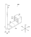
例えば、第一実施形態に係る清掃具用スタンド100の変形例としては、図12に示す清掃具用スタンド100Dのように、底面部111の背面部112が接続されているのとは反対側の端部(図12においては前端部)に、収納部140が備えられる。
いずれの実施形態においても、清掃具用スタンドは、交換用の使用前のヘッド部220を収納する収納部を備えてもよい。
例えば、第一実施形態に係る清掃具用スタンド100の変形例としては、図12に示す清掃具用スタンド100Dのように、底面部111の背面部112が接続されているのとは反対側の端部(図12においては前端部)に、収納部140が備えられる。
(収納部)
収納部140は、例えば、図12に示すように、複数の収納スペース141を有する棚状に形成され、それぞれの収納スペース141が、ヘッド部220を収納できる大きさを有する。
また、最下部の収納スペース141も、底面部111の上面側よりも高い位置に形成されていることが望ましい。これによって、交換用のヘッド部220が、使用後の柄部210の水分によって濡れてしまうことを防止できる。
収納部140は、例えば、図12に示すように、複数の収納スペース141を有する棚状に形成され、それぞれの収納スペース141が、ヘッド部220を収納できる大きさを有する。
また、最下部の収納スペース141も、底面部111の上面側よりも高い位置に形成されていることが望ましい。これによって、交換用のヘッド部220が、使用後の柄部210の水分によって濡れてしまうことを防止できる。
本発明は、清掃具用スタンドの製造分野において好適に利用できる。
200、200A 清掃具
210、210A、210B、210C 柄部
220 ヘッド部
100、100A、100B、100C、100D 清掃具用スタンド
110、110A 本体部
111 底面部
111a 載置面
112 背面部
120、120B 第一支持部
130、130A、130B、130C 第二支持部
140 収納部
210、210A、210B、210C 柄部
220 ヘッド部
100、100A、100B、100C、100D 清掃具用スタンド
110、110A 本体部
111 底面部
111a 載置面
112 背面部
120、120B 第一支持部
130、130A、130B、130C 第二支持部
140 収納部
Claims (6)
- 清掃対象物にヘッド部を押し付けて清掃する清掃具又は当該清掃具の柄部を保管対象物とする清掃具用スタンドであって、
床面等に載置される載置面を有する本体部と、
前記本体部に備えられ、前記保管対象物を支持する第一支持部及び第二支持部と、を備え、
前記第一支持部及び前記第二支持部は、前記保管対象物が前記本体部に接しない状態で、前記保管対象物を支持することを特徴とする清掃具用スタンド。 - 前記本体部は、前記載置面が形成された底面部と、前記底面部から立設する背面部と、を備え、
前記第一支持部は前記底面部に備えられ、前記第二支持部は前記背面部に備えられていることを特徴とする請求項1に記載の清掃具用スタンド。 - 前記本体部は、前記載置面が形成された底面部を備え、
前記第一支持部及び前記第二支持部は、前記底面部に備えられていることを特徴とする請求項1に記載の清掃具用スタンド。 - 前記本体部は、前記載置面が形成された底面部と、前記底面部から立設する背面部と、を備え、
前記第一支持部及び前記第二支持部は、前記背面部に、同一の高さにおいて、所定の間隔を空けて同一方向へと延出するように備えられていることを特徴とする請求項1に記載の清掃具用スタンド。 - 前記第二支持部は、水平方向へと突出する柱状に形成されていることを特徴とする請求項2に記載の清掃具用スタンド。
- 前記清掃具は、前記柄部と前記ヘッド部とが着脱自在に形成され、
前記本体部に、前記ヘッド部を収納する収納部を備えることを特徴とする請求項1から5のいずれか一項に記載の清掃具用スタンド。
Applications Claiming Priority (2)
| Application Number | Priority Date | Filing Date | Title |
|---|---|---|---|
| JP2018-121249 | 2018-06-26 | ||
| JP2018121249A JP7218107B2 (ja) | 2018-06-26 | 2018-06-26 | 清掃具用スタンド及び清掃具保管システム |
Publications (1)
| Publication Number | Publication Date |
|---|---|
| WO2020004084A1 true WO2020004084A1 (ja) | 2020-01-02 |
Family
ID=68986383
Family Applications (1)
| Application Number | Title | Priority Date | Filing Date |
|---|---|---|---|
| PCT/JP2019/023735 Ceased WO2020004084A1 (ja) | 2018-06-26 | 2019-06-14 | 清掃具用スタンド |
Country Status (2)
| Country | Link |
|---|---|
| JP (1) | JP7218107B2 (ja) |
| WO (1) | WO2020004084A1 (ja) |
Citations (6)
| Publication number | Priority date | Publication date | Assignee | Title |
|---|---|---|---|---|
| US2515890A (en) * | 1948-04-14 | 1950-07-18 | John J Ollman | Brush holder |
| JPS62192355U (ja) * | 1986-05-26 | 1987-12-07 | ||
| JP2002282186A (ja) * | 2001-03-22 | 2002-10-02 | Toshikazu Kitanishi | 水切り用支持具および水切り具 |
| US20040088808A1 (en) * | 2002-09-05 | 2004-05-13 | Vitantonio Marc. L. | Toilet cleaning apparatus and caddy |
| JP2005304878A (ja) * | 2004-04-23 | 2005-11-04 | Koichiro Tanaka | 歯ブラシ類のホルダ具 |
| US20150027914A1 (en) * | 2013-07-23 | 2015-01-29 | S.C. Johnson & Son, Inc. | Toilet caddy assembly and method of forming a toilet caddy assembly |
Family Cites Families (2)
| Publication number | Priority date | Publication date | Assignee | Title |
|---|---|---|---|---|
| JPS5850912A (ja) * | 1981-09-24 | 1983-03-25 | 愛工業株式会社 | ぬれ物立て |
| CN103892780A (zh) | 2012-12-28 | 2014-07-02 | 天津市汇波泉商贸有限公司 | 一种新型清洁工具 |
-
2018
- 2018-06-26 JP JP2018121249A patent/JP7218107B2/ja active Active
-
2019
- 2019-06-14 WO PCT/JP2019/023735 patent/WO2020004084A1/ja not_active Ceased
Patent Citations (6)
| Publication number | Priority date | Publication date | Assignee | Title |
|---|---|---|---|---|
| US2515890A (en) * | 1948-04-14 | 1950-07-18 | John J Ollman | Brush holder |
| JPS62192355U (ja) * | 1986-05-26 | 1987-12-07 | ||
| JP2002282186A (ja) * | 2001-03-22 | 2002-10-02 | Toshikazu Kitanishi | 水切り用支持具および水切り具 |
| US20040088808A1 (en) * | 2002-09-05 | 2004-05-13 | Vitantonio Marc. L. | Toilet cleaning apparatus and caddy |
| JP2005304878A (ja) * | 2004-04-23 | 2005-11-04 | Koichiro Tanaka | 歯ブラシ類のホルダ具 |
| US20150027914A1 (en) * | 2013-07-23 | 2015-01-29 | S.C. Johnson & Son, Inc. | Toilet caddy assembly and method of forming a toilet caddy assembly |
Also Published As
| Publication number | Publication date |
|---|---|
| JP2020000385A (ja) | 2020-01-09 |
| JP7218107B2 (ja) | 2023-02-06 |
Similar Documents
| Publication | Publication Date | Title |
|---|---|---|
| US8763197B2 (en) | Cleaning article with non-planar element in place of strips | |
| US9408518B2 (en) | Retainers for a device having removable floor sheets | |
| CA2866704C (en) | Cleaning article with apertured sheet and tow fibers | |
| JP6553751B2 (ja) | 多層ギャザーストリップ要素を有する掃除用品 | |
| CA2692504A1 (en) | Plural sided cleaning implement | |
| US9386899B2 (en) | Foldable duster | |
| JP2020000943A (ja) | 差異的結合部パターンを有するストリップを有する床掃除用品 | |
| JP2020000385A (ja) | 清掃具用スタンド | |
| JP6563980B2 (ja) | 掃除具 | |
| JP7187233B2 (ja) | 清掃具用柄及び清掃具 | |
| JP6571132B2 (ja) | 掃除具 | |
| US20060200926A1 (en) | Carpet brush for hair removal | |
| CN110708997B (zh) | 扫除工具 | |
| JP7309473B2 (ja) | 清掃具 | |
| JP6635983B2 (ja) | 掃除具 | |
| JP2021126431A (ja) | 清掃用治具 | |
| JP7121560B2 (ja) | 清掃具用柄及び清掃具 | |
| JP5917872B2 (ja) | 清掃用具 | |
| JP3036950U (ja) | カーペット等の掃除用具 | |
| JP3070925B1 (ja) | 吸引式掃除機用清掃補助具 | |
| EP3024373B1 (en) | Retainers for a device having removable floor sheets | |
| JP6297831B2 (ja) | 清掃シート及びこれを有する清掃用具 | |
| JP2008114014A (ja) | 折り畳みちりとり | |
| JP2019208618A (ja) | 清掃具用ヘッド部、清掃具及び清掃具用ヘッド部の製造方法 | |
| TW201601669A (zh) | 一種清潔用膠棉條、一種膠棉拖把及一種清潔裝置 |
Legal Events
| Date | Code | Title | Description |
|---|---|---|---|
| 121 | Ep: the epo has been informed by wipo that ep was designated in this application |
Ref document number: 19825845 Country of ref document: EP Kind code of ref document: A1 |
|
| NENP | Non-entry into the national phase |
Ref country code: DE |
|
| 122 | Ep: pct application non-entry in european phase |
Ref document number: 19825845 Country of ref document: EP Kind code of ref document: A1 |