WO2020003974A1 - 鞍乗り型車両のクラッチ制御装置 - Google Patents
鞍乗り型車両のクラッチ制御装置 Download PDFInfo
- Publication number
- WO2020003974A1 WO2020003974A1 PCT/JP2019/022721 JP2019022721W WO2020003974A1 WO 2020003974 A1 WO2020003974 A1 WO 2020003974A1 JP 2019022721 W JP2019022721 W JP 2019022721W WO 2020003974 A1 WO2020003974 A1 WO 2020003974A1
- Authority
- WO
- WIPO (PCT)
- Prior art keywords
- wheel speed
- clutch
- control
- speed
- vehicle
- Prior art date
- Legal status (The legal status is an assumption and is not a legal conclusion. Google has not performed a legal analysis and makes no representation as to the accuracy of the status listed.)
- Ceased
Links
Images









Classifications
-
- F—MECHANICAL ENGINEERING; LIGHTING; HEATING; WEAPONS; BLASTING
- F16—ENGINEERING ELEMENTS AND UNITS; GENERAL MEASURES FOR PRODUCING AND MAINTAINING EFFECTIVE FUNCTIONING OF MACHINES OR INSTALLATIONS; THERMAL INSULATION IN GENERAL
- F16D—COUPLINGS FOR TRANSMITTING ROTATION; CLUTCHES; BRAKES
- F16D48/00—External control of clutches
- F16D48/06—Control by electric or electronic means, e.g. of fluid pressure
-
- F—MECHANICAL ENGINEERING; LIGHTING; HEATING; WEAPONS; BLASTING
- F16—ENGINEERING ELEMENTS AND UNITS; GENERAL MEASURES FOR PRODUCING AND MAINTAINING EFFECTIVE FUNCTIONING OF MACHINES OR INSTALLATIONS; THERMAL INSULATION IN GENERAL
- F16D—COUPLINGS FOR TRANSMITTING ROTATION; CLUTCHES; BRAKES
- F16D2500/00—External control of clutches by electric or electronic means
- F16D2500/10—System to be controlled
- F16D2500/102—Actuator
- F16D2500/1026—Hydraulic
-
- F—MECHANICAL ENGINEERING; LIGHTING; HEATING; WEAPONS; BLASTING
- F16—ENGINEERING ELEMENTS AND UNITS; GENERAL MEASURES FOR PRODUCING AND MAINTAINING EFFECTIVE FUNCTIONING OF MACHINES OR INSTALLATIONS; THERMAL INSULATION IN GENERAL
- F16D—COUPLINGS FOR TRANSMITTING ROTATION; CLUTCHES; BRAKES
- F16D2500/00—External control of clutches by electric or electronic means
- F16D2500/10—System to be controlled
- F16D2500/11—Application
- F16D2500/1107—Vehicles
- F16D2500/1117—Motorcycle
-
- F—MECHANICAL ENGINEERING; LIGHTING; HEATING; WEAPONS; BLASTING
- F16—ENGINEERING ELEMENTS AND UNITS; GENERAL MEASURES FOR PRODUCING AND MAINTAINING EFFECTIVE FUNCTIONING OF MACHINES OR INSTALLATIONS; THERMAL INSULATION IN GENERAL
- F16D—COUPLINGS FOR TRANSMITTING ROTATION; CLUTCHES; BRAKES
- F16D2500/00—External control of clutches by electric or electronic means
- F16D2500/30—Signal inputs
- F16D2500/31—Signal inputs from the vehicle
- F16D2500/3108—Vehicle speed
- F16D2500/3109—Vehicle acceleration
-
- F—MECHANICAL ENGINEERING; LIGHTING; HEATING; WEAPONS; BLASTING
- F16—ENGINEERING ELEMENTS AND UNITS; GENERAL MEASURES FOR PRODUCING AND MAINTAINING EFFECTIVE FUNCTIONING OF MACHINES OR INSTALLATIONS; THERMAL INSULATION IN GENERAL
- F16D—COUPLINGS FOR TRANSMITTING ROTATION; CLUTCHES; BRAKES
- F16D2500/00—External control of clutches by electric or electronic means
- F16D2500/30—Signal inputs
- F16D2500/31—Signal inputs from the vehicle
- F16D2500/3114—Vehicle wheels
- F16D2500/3115—Vehicle wheel speed
-
- F—MECHANICAL ENGINEERING; LIGHTING; HEATING; WEAPONS; BLASTING
- F16—ENGINEERING ELEMENTS AND UNITS; GENERAL MEASURES FOR PRODUCING AND MAINTAINING EFFECTIVE FUNCTIONING OF MACHINES OR INSTALLATIONS; THERMAL INSULATION IN GENERAL
- F16D—COUPLINGS FOR TRANSMITTING ROTATION; CLUTCHES; BRAKES
- F16D2500/00—External control of clutches by electric or electronic means
- F16D2500/30—Signal inputs
- F16D2500/31—Signal inputs from the vehicle
- F16D2500/3114—Vehicle wheels
- F16D2500/3118—Slip of vehicle wheels
Definitions
- the present invention relates to a clutch control device for a saddle type vehicle.
- This application claims priority based on Japanese Patent Application No. 2018-123814 filed in Japan on June 29, 2018 and Japanese Patent Application No. 2018-204514 filed in Japan on October 30, 2018. , The contents of which are incorporated herein.
- a clutch device for connecting and disconnecting power transmission between a prime mover and drive wheels may be provided with a back torque limiter.
- the back torque limiter is a mechanism for limiting an engine brake (including a regenerative brake when the electric motor includes an electric motor) acting on the drive wheels due to the resistance of the motor.
- the back torque limiter mechanically reduces the clutch capacity when a back torque exceeding a specified value acts on a cam mechanism provided in the clutch device.
- the back torque is a torque at which the engine is turned by the driving force from the driving wheels when the vehicle decelerates.
- the clutch device releases the back torque by the operation of the back torque limiter to prevent application of excessive engine brake to the drive wheels.
- the above-mentioned back torque is set to a specified value or more.
- the above-mentioned back torque can be more than the above-mentioned specification in a state where the driving wheels are in contact with the ground and are sufficiently gripped (in a state where there is a sufficient contact load).
- the ground load of the rear wheel which is the driving wheel, becomes too small, and the rear wheel may float off the road surface. If the rear wheel loses grip, the rear wheel will suddenly decelerate when the engine brakes.
- a clutch control device for a saddle-ride type vehicle includes a rear wheel that is a driving wheel, a front wheel that is a driven wheel, a driving motor for traveling, and a motor for driving the vehicle.
- the control unit may control the rear wheel speed, which is the rotation speed of the rear wheel, to be higher than the front wheel speed, which is the rotation speed of the front wheel. Then, it may be determined that the rear wheel is in the ground contact load lowering state based on that the rear wheel has become lower than a predetermined difference.
- the control unit may correct the front wheel speed as the rear wheel speed to be compared with the front wheel speed. Wheel speed may be used.
- the corrected wheel speed may be a change amount of the rear wheel speed at the same time as the front wheel speed at the time of the wheel speed correction. It may be obtained by adding.
- the saddle-ride type vehicle is in an upright posture, and the difference between the front and rear wheel speeds is less than a predetermined value.
- the wheel speed correction may be started from a specific point in time when the throttle of the prime mover is closed.
- a value obtained by dividing the front wheel speed by the corrected wheel speed is used as a first parameter
- a value obtained by subtracting the corrected wheel speed from the front wheel speed may be used as a second parameter
- the slipper control may be interposed according to at least one of the first parameter and the second parameter.
- the slipper control when the vehicle speed is equal to or higher than the first vehicle speed, the slipper control is interposed according to the first parameter, and the vehicle speed is reduced to the first vehicle speed.
- the slipper control When the vehicle speed is lower than one vehicle speed and higher than or equal to the second vehicle speed, the slipper control may be interposed according to the second parameter.
- the control unit may open the throttle of the prime mover with the slipper control interposed.
- the intervention of the slipper control may be canceled in response to at least one of the following facts and / or that the reduced state of the contact load of the rear wheel has been eliminated.
- the clutch capacity is reduced when a decrease in the ground contact load such that the rear wheel floats when the saddle-ride type vehicle is decelerated is detected.
- Slipper control can be performed. As a result, it is possible to secure an appropriate engine brake during normal traveling while ensuring the ground contact load of the rear wheels, and to shift to slipper control during rapid deceleration when the rear wheels float. Since the slipper control weakens the engine brake of the rear wheel, the occurrence of hopping and snaking due to the engine brake when the ground load of the rear wheel is released is suppressed.
- the clutch capacity can be made variable as compared with a mechanical back torque limiter.
- the rear wheel speed is lower than the front wheel speed, so that the ground load of the rear wheel is released. Can be easily and reliably determined.
- the actual front and rear wheel speeds are affected not only by the difference in the tire outer diameter of the front and rear wheels, but also by the circumferential change of the tire. . Changes in the circumference of the tire are caused by, for example, the brand of the tire, wear, expansion due to centrifugal force, and the like. For this reason, even if the front and rear wheels are rotating without slipping on the road surface, there may be a difference in front and rear wheel speed due to a change in the circumference of the tire.
- a corrected wheel speed for comparison is calculated based on the front wheel speed, and the corrected wheel speed is compared with the front wheel speed. It is possible to accurately detect a decrease in wheel speed and prevent an inadvertent decrease in clutch capacity (a decrease in engine brake).
- the amount of change in the rear wheel speed is added to the front wheel speed to correct the wheel speed.
- the load can be reduced.
- the saddle-ride type vehicle is in a decelerating state in which the throttle of the prime mover is closed in an upright position, and the difference between the front and rear wheel speeds is the rear wheel.
- an appropriate value is selected from the two types of parameters to determine the intervention of the slipper control (the determination that the rear wheel is slipping).
- the slipper control can be performed with a minimum necessary frequency.
- a slip determination can be performed by selecting an appropriate parameter according to the vehicle speed.
- the slipper control when the vehicle speed is low, the slipper control is not intervened, so that the system load can be suppressed.
- the clutch control device for a saddle-ride type vehicle described in the above (9) of the present invention at least one of the fact that the saddle-ride type vehicle has shifted to acceleration and that the reduction in the contact load of the rear wheels has been eliminated.
- the clutch control device for a saddle-ride type vehicle described in the above (10) of the present invention in a region where the bank angle of the vehicle body is large, an accurate wheel speed difference is obtained because the patterns of the tread surfaces of the front and rear wheels are different.
- the bank angle of the vehicle body is equal to or larger than a predetermined value, the slipper control of the clutch is performed regardless of the wheel speed difference.
- FIG. 2 is a left side view of the motorcycle according to the embodiment of the present invention.
- FIG. 2 is a sectional view of a transmission and a change mechanism of the motorcycle. It is a schematic explanatory view of a clutch operation system including a clutch actuator.
- FIG. 2 is a block diagram of a transmission system.
- FIG. 5 is an explanatory diagram showing a transition of a clutch control mode.
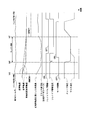
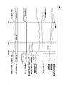
- 4 is a graph showing an outline of slipper control during deceleration of the motorcycle. It is a graph which shows the time change of the control parameter of the slipper control at the time of the above-mentioned deceleration. It is a graph which shows the time change of the control parameter of the said slipper control at the time of the said deceleration.
- FIG. 1 shows an outline of slipper control during deceleration of the motorcycle. It is a graph which shows the time change of the control parameter of the slipper control at the time of the above-mentioned deceleration. It is a graph
- FIG. 3 is an explanatory diagram showing a vehicle body situation at the time of deceleration of the motorcycle. It is a graph which shows the outline of the wheel speed correction of the slipper control at the time of the above-mentioned deceleration.
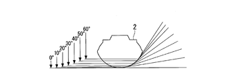
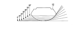
- FIG. 14 is an operation explanatory view of the second embodiment, and is a cross-sectional view showing a change in a contact angle and a contact point of a front wheel.
- FIG. 10 is an operation explanatory view of the second embodiment, and is a cross-sectional view showing a change between a contact angle and a contact point of a rear wheel. It is an operation explanatory view of the second embodiment, and is a graph showing a correlation between a circumferential length change rate ratio of front and rear wheels and a bank angle.
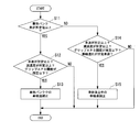
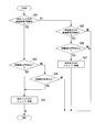
- 9 is a flowchart illustrating a process performed by an ECU when determining whether to shift to wheel speed correction in the first and second embodiments. It is a flowchart which shows the process which ECU performs at the time of determining whether to perform slipper control in 1st and 2nd embodiment. It is a flowchart which shows the process performed by ECU at the time of determining whether to end the slipper control in the first and second embodiments.
- the first embodiment is applied to a motorcycle 1 as an example of a saddle type vehicle.
- a front wheel 2 of the motorcycle 1 is supported by lower ends of a pair of left and right front forks 3.
- the upper portions of the left and right front forks 3 are supported by a head pipe 6 at the front end of a vehicle body frame 5 via a steering stem 4.
- a bar-type steering handle 4 a is mounted on the top bridge of the steering stem 4.
- the vehicle body frame 5 includes a head pipe 6, a main tube 7 extending downward and rearward from a center of the head pipe 6 in a vehicle width direction (lateral direction), a left and right pivot frame 8 extending below a rear end of the main tube 7, And a seat frame 9 connected to the rear of the tube 7 and the left and right pivot frames 8.
- the front ends of the swing arms 11 are pivotably supported by the left and right pivot frames 8. At the rear end of the swing arm 11, a rear wheel 12 of the motorcycle 1 is supported.
- a fuel tank 18 is supported above the left and right main tubes 7.
- a front seat 19 and a rear seat cover 19a are supported side by side.
- the periphery of the seat frame 9 is covered with a rear cowl 9a.
- a power unit PU which is a prime mover of the motorcycle 1, is suspended.
- the power unit PU is linked to the rear wheel 12 via, for example, a chain-type transmission mechanism.
- the power unit PU integrally includes an engine (internal combustion engine, prime mover) 13 located on the front side and a transmission 21 located on the rear side.
- the engine 13 is, for example, a multi-cylinder engine in which the rotation axis of a crankshaft 14 extends along the left-right direction (vehicle width direction).
- the engine 13 has a cylinder 16 erected above a front part of the crankcase 15.
- the rear part of the crankcase 15 is a transmission case 17 that houses the transmission 21.
- the transmission 21 is a stepped transmission having a main shaft 22, a counter shaft 23, and a transmission gear group 24 extending over both shafts 22, 23.
- the counter shaft 23 constitutes the transmission 21 and thus the output shaft of the power unit PU.
- An end of the counter shaft 23 projects to the rear left side of the crankcase 15 and is connected to the rear wheel 12 via the above-mentioned chain type transmission mechanism.
- the transmission gear group 24 has gears for the number of gears supported by the shafts 22 and 23, respectively.
- the transmission 21 is of a constant mesh type in which the corresponding gear pairs of the transmission gear group 24 are always meshed between the two shafts 22 and 23.
- the plurality of gears supported by both shafts 22 and 23 are classified into a free gear rotatable with respect to the corresponding shaft, and a slide gear (shifter) spline-fitted to the corresponding shaft.
- One of the free gear and the slide gear has an axially convex dog, and the other has an axially concave slot for engaging the dog. That is, the transmission 21 is a so-called dog mission.
- the main shaft 22 and the counter shaft 23 of the transmission 21 are arranged in front of and behind the crankshaft 14.
- a clutch device 26 operated by a clutch actuator 50 (see FIG. 3) is coaxially arranged.
- the clutch device 26 is, for example, a wet multi-plate clutch, and is a so-called normally open clutch. That is, the clutch device 26 is in a connected state in which power can be transmitted by supplying hydraulic pressure from the clutch actuator 50, and returns to a disconnected state in which power cannot be transmitted when hydraulic pressure is not supplied from the clutch actuator 50.
- the rotational power of the crankshaft 14 is transmitted to the main shaft 22 via the clutch device 26, and transmitted from the main shaft 22 to the counter shaft 23 via an arbitrary gear pair of the transmission gear group 24.
- a drive sprocket 27 of the above-described chain type transmission mechanism is attached to a left end portion of the countershaft 23 protruding to the rear left side of the crankcase 15.
- the clutch device 26 includes a back torque limiter (not shown). The back torque limiter mechanically reduces the clutch capacity when a back torque exceeding a specified value acts on a cam mechanism provided in the clutch device 26.
- a change mechanism 25 for switching a gear pair of the transmission gear group 24 Above the rear of the transmission 21 is accommodated a change mechanism 25 for switching a gear pair of the transmission gear group 24.
- the change mechanism 25 operates a plurality of shift forks 36 a in accordance with a pattern of a lead groove formed on the outer periphery of the shift gear group 24 by rotating a hollow cylindrical shift drum 36 parallel to the shafts 22 and 23.
- the gear pair used for power transmission between the two shafts 22 and 23 is switched.
- the change mechanism 25 has a shift spindle 31 parallel to the shift drum 36.
- the shift arm 31a fixed to the shift spindle 31 rotates the shift drum 36, and moves the shift fork 36a in the axial direction according to the pattern of the lead groove, so that the power within the transmission gear group 24 is changed.
- the transmissible gear pair is switched (that is, the gear position is switched).
- the shift spindle 31 has a shaft outer portion 31b protruding outward (leftward) in the vehicle width direction of the crankcase 15 so that the change mechanism 25 can be operated.
- a shift load sensor 42 (shift operation detecting means) is coaxially mounted on the shaft outer portion 31b of the shift spindle 31.
- a swing lever 33 is attached to the shaft outer portion 31b of the shift spindle 31 (or the rotation shaft of the shift load sensor 42).
- the swing lever 33 extends rearward from a base end portion 33a which is clamped and fixed to the shift spindle 31 (or the rotation shaft), and the upper end portion of a link rod 34 swings at a tip end portion 33b thereof via an upper ball joint 34a. It is movably connected.
- a lower end of the link rod 34 is swingably connected to a shift pedal 32 operated by a driver with a foot via a lower ball joint (not shown).
- the front end of the shift pedal 32 is supported at the lower part of the crankcase 15 via a shaft extending in the left-right direction so as to be vertically swingable.
- a pedal portion for hanging the driver's toe placed on the step 32a is provided, and at the front and rear intermediate portion of the shift pedal 32, the lower end of a link rod 34 is connected.
- the driver performs only the shifting operation of the transmission 21 (the foot operation of the shift pedal 32), and the connecting / disconnecting operation of the clutch device 26 is automatically performed by electric control according to the operation of the shift pedal 32.
- a so-called semi-automatic transmission system (automatic clutch-type transmission system) is adopted.
- the transmission system includes a clutch actuator 50, an ECU 60 (Electronic Control Unit, control unit), and various sensors 41 to 45.
- the ECU 60 detects detection information from a gear position sensor 41 that detects a gear position based on the rotation angle of the shift drum 36, a shift load sensor 42 (for example, a torque sensor) that detects an operating torque input to the shift spindle 31, and a throttle opening.
- a gear position sensor 41 that detects a gear position based on the rotation angle of the shift drum 36
- a shift load sensor 42 for example, a torque sensor
- the operation of the clutch actuator 50 is controlled, and the operation of the ignition device 46 and the fuel injection device 47 are controlled.
- the vehicle speed sensor 44 includes a front wheel speed sensor 44f that detects the rotation speed of the front wheel 2, and a rear wheel speed sensor 44r that detects the rotation speed of the rear wheel 12.
- the engine speed is controlled by a throttle by wire (TBW) including a throttle valve and an accelerator grip.
- TW throttle by wire
- the ECU 60 also receives detection information from oil pressure sensors 57 and 58, a shift operation detection switch (shift neutral switch) 48, and a gyro sensor 49 that detects the state (movement) of the vehicle body.
- the gyro sensor 49 is an IMU (inertial measurement unit: inertial measurement device), and outputs a signal corresponding to the acceleration component in the detection direction to the ECU 60.
- the gyro sensor 49 may be built in the ECU 60.
- the ECU 60 includes a hydraulic control unit 61 and a wheel speed difference determination unit (rear lift detection unit) 62.
- the hydraulic control unit 61 includes a slipper control unit 61a.
- the wheel speed difference determination section 62 includes a wheel speed correction section 62a.
- Reference numeral 60A in the figure indicates the clutch control device of the first embodiment.
- the clutch actuator 50 is controlled to be operated by the ECU 60, so that the hydraulic pressure for connecting and disconnecting the clutch device 26 can be controlled.
- the clutch actuator 50 includes an electric motor 52 (hereinafter, simply referred to as a motor 52) as a driving source, and a master cylinder 51 driven by the motor 52.
- the clutch actuator 50 and the hydraulic circuit device 53 provided between the master cylinder 51 and the hydraulic supply / discharge port 50p constitute an integral clutch control unit 50A.
- the ECU 60 calculates a target value (a target hydraulic pressure) of the hydraulic pressure supplied to the slave cylinder 28 for connecting and disconnecting the clutch device 26 based on a preset calculation program.
- the clutch control unit 50A is controlled so that the hydraulic pressure on the 28 side (slave hydraulic pressure) approaches the target hydraulic pressure.
- the master cylinder 51 allows the piston 51b in the cylinder main body 51a to stroke by the driving of the motor 52 so that the hydraulic oil in the cylinder main body 51a can be supplied to and discharged from the slave cylinder 28.
- reference numeral 55 denotes a conversion mechanism as a ball screw mechanism
- reference numeral 54 denotes a transmission mechanism extending over the motor 52 and the conversion mechanism 55
- reference numeral 51e denotes a reservoir connected to the master cylinder 51.
- the hydraulic circuit device 53 has a valve mechanism (solenoid valve 56) for opening or closing an intermediate portion of a main oil passage (hydraulic oil supply / discharge oil passage) 53m extending from the master cylinder 51 to the clutch device 26 side (slave cylinder 28 side). are doing.
- the main oil passage 53m of the hydraulic circuit device 53 is divided into an upstream oil passage 53a closer to the master cylinder 51 than the solenoid valve 56, and a downstream oil passage 53b closer to the slave cylinder 28 than the solenoid valve 56.
- the hydraulic circuit device 53 further includes a bypass oil passage 53c that bypasses the solenoid valve 56 and communicates the upstream oil passage 53a and the downstream oil passage 53b.
- the solenoid valve 56 is a so-called normally open valve.
- the bypass oil passage 53c is provided with a one-way valve 53c1 that allows hydraulic oil to flow only in the direction from the upstream side to the downstream side.
- An upstream oil pressure sensor 57 for detecting the oil pressure of the upstream oil passage 53a is provided upstream of the solenoid valve 56.
- a downstream oil pressure sensor 58 for detecting the oil pressure of the downstream oil passage 53b is provided downstream of the solenoid valve 56.
- the clutch control unit 50A is housed, for example, in the rear cowl 9a.
- the slave cylinder 28 is attached to the rear left side of the crankcase 15.
- the clutch control unit 50A and the slave cylinder 28 are connected via a hydraulic pipe 53e (see FIG. 3).
- the slave cylinder 28 is coaxially arranged on the left side of the main shaft 22.
- the slave cylinder 28 presses a push rod 28a penetrating through the main shaft 22 to the right.
- the slave cylinder 28 presses the push rod 28a to the right to operate the clutch device 26 to the connected state via the push rod 28a.
- the slave cylinder 28 releases the pressing of the push rod 28a and returns the clutch device 26 to the disconnected state.
- a solenoid valve 56 is provided in the hydraulic circuit device 53 of the clutch control unit 50A, and the solenoid valve 56 is closed after hydraulic pressure is supplied to the clutch device 26 side. Thereby, energy consumption is suppressed by maintaining the supply oil pressure to the clutch device 26 side and supplementing the oil pressure by the pressure decrease (recharge by the leak amount).
- the clutch control device 60A of the first embodiment has three types of clutch control modes.
- the clutch control mode includes a clutch control mode changeover switch 59 (FIG. 4) among three modes: an automatic mode M1 for performing automatic control, a manual mode M2 for performing manual operation, and a manual intervention mode M3 for performing temporary manual operation.
- the state changes appropriately according to the operation of the clutch lever 4b (see FIG. 1) and the clutch lever 4b (see FIG. 1).
- An object including the manual mode M2 and the manual intervention mode M3 is referred to as a manual system M2A.
- the clutch control device 60A also functions as a clutch-by-wire system in which the clutch lever 4b and the clutch device 26 are electrically connected.
- the automatic mode M1 is a mode in which the clutch device 26 is controlled by calculating a clutch capacity suitable for a running state by automatic start / shift control.
- the manual mode M2 is a mode in which the clutch capacity is calculated in accordance with a clutch operation instruction from the occupant to control the clutch device 26.
- the manual intervention mode M3 is a temporary manual operation mode in which a clutch operation instruction from an occupant is received during the automatic mode M1, and a clutch capacity is calculated from the clutch operation instruction to control the clutch device 26. It should be noted that, when the occupant stops operating the clutch lever 4b (completely releases) during the manual intervention mode M3, the mode is set to return to the auto mode M1.
- the clutch control device 60 ⁇ / b> A of the first embodiment generates an oil pressure for clutch control by driving an oil pump (not shown) with the rotational driving force of the engine 13. For this reason, the clutch control device 60A starts the control from the clutch-off state (disconnected state) in the auto mode M1 when the system is started. Further, the clutch control device 60A is set to return to the clutch off in the automatic mode M1 because the clutch operation is not required when the engine 13 is stopped.
- the clutch control is performed automatically, and the motorcycle 1 can run without operating the lever.
- the clutch capacity is controlled by the throttle opening, engine speed, vehicle speed, and shift sensor output.
- the motorcycle 1 can be started without stalling only by the throttle operation, and can be shifted only by the shift operation.
- the clutch device 26 may be automatically disconnected at an extremely low speed corresponding to idling.
- the manual intervention mode M3 is set by gripping the clutch lever 4b, and the clutch device 26 can be arbitrarily disengaged.
- the clutch capacity is controlled by the lever operation by the occupant.
- the auto mode M1 and the manual mode M2 can be switched by operating the clutch control mode switch 59 (see FIG. 4) while the vehicle is stopped.
- the clutch control device 60A may include an indicator indicating that the lever operation is valid at the time of transition to the manual system M2A (manual mode M2 or manual intervention mode M3).
- the clutch control is basically performed manually, and the clutch oil pressure can be controlled according to the operation angle of the clutch lever 4b.
- the connection and disconnection of the clutch device 26 can be controlled with the intention of the occupant, and the vehicle can be connected and run even at an extremely low speed equivalent to idling.
- the engine may stall depending on the lever operation, and automatic start cannot be performed only by the throttle operation.
- the clutch control automatically intervenes during the shift operation.
- the clutch actuator 50 automatically connects and disconnects the clutch device 26. However, when the manual clutch operation on the clutch lever 4b is performed, the manual operation is temporarily intervened in the automatic control of the clutch device 26. (Manual intervention mode M3).
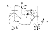
- the front contact load Mg1 front wheel contact load
- the front grip force Mg3 mainly reduces the speed. That is, when the inertia force Fb1 due to the deceleration acts on the center of gravity G of the vehicle body, the component force Fb2 of the inertia force Fb1 acts forward and upward with respect to the front contact position Pg1, and the vehicle is based on the front contact position Pg1. Generate a moment. As a result, the rear ground contact load Mg2 comes off (decreases), and the rear grip force Mg4 decreases. Depending on the magnitude of the vehicle deceleration, the rear contact load Mg2 becomes zero, and the rear wheel 12 floats from the road surface (the rear grip force Mg4 becomes zero).
- the clutch capacity is reduced by control of the automatic clutch system (slipper control during deceleration). Thereby, the occurrence of hopping and snaking is suppressed, and the rear-wheel contact property is ensured. Since it is determined whether or not the rear wheel 12 has floated, the clutch capacity is reduced, so that the engine brake is prevented from being carelessly reduced as compared with the related art, and an appropriate engine brake is secured. In addition, responsiveness and controllability at the time of control are better than engine brake control by engine control.
- the determination as to whether or not the vehicle is in the rear lift state is performed by the wheel speed difference determination unit 62 of the ECU 60.
- the wheel speed difference determination unit 62 determines that the vehicle is in the rear lift state due to rapid deceleration. In other words, the wheel speed difference determination unit 62 detects that the vehicle is in the rear lift state due to rapid deceleration based on the detection signal of the brake switch and the detection signals of the front and rear wheel speed sensors 44f and 44r.
- the slipper control unit 61a of the hydraulic control unit 61 of the ECU 60 performs slipper control on the clutch device 26.
- the slipper control unit 61a calculates a target value (a target hydraulic pressure) of the hydraulic pressure supplied to the slave cylinder 28 based on a preset calculation program, and controls the clutch control unit 50A.
- the slipper control is control for reducing the clutch capacity of the clutch device 26 (control for reducing the target hydraulic pressure).
- Slipper control causes the clutch device 26 to slip as in the case of the back torque limiter.
- the slipper control causes the clutch device 26 to generate clutch differential rotation (clutch slip).
- the slipper control releases the back torque acting on the clutch device 26 and suppresses the engine brake acting on the rear wheel 12.
- the slipper control suppresses vehicle body behavior such as hopping and snaking due to a decrease in the contact property of the rear wheel 12 (rear wheel contact property).
- the rear wheel speed Vr is greatly inclined with respect to front wheel speed Vf. It falls with. That is, at the time of deceleration such that the rear wheel 12 floats, the rear wheel speed Vr becomes lower than the front wheel speed Vf.
- the gradients of the lines indicating the front and rear wheel speeds Vf and Vr in the graph of FIG. 6 are decelerations Af and Ar of the front and rear wheels 2 and 12, respectively, and the difference between the front and rear wheel speeds Vf and Vr at the same timing is the front and rear wheel speed difference D. I do.
- the clutch device 26 is in the engaged state in which the clutch capacity is maintained at the maximum value until the timing tm1 at which the front and rear wheel speed difference D reaches the predetermined first specified value K1 (difference). At this time, the clutch device 26 changes while keeping the clutch differential rotation at substantially zero. The rear wheel 12 is lifted during the rapid deceleration.
- the clutch device 26 starts deceleration control (slipper control) at a timing tm1 at which the front and rear wheel speed difference D becomes the first specified value K1.
- the clutch device 26 is in a state where the clutch capacity is reduced after the timing tm1. That is, the clutch device 26 is in the half-clutch state after the timing tm1, and generates a clutch differential rotation (clutch slip) in the case where there is no slipper control (line Dc 'in the diagram) (line Dc in the diagram). Then, the rear wheel speed Vr with the slipper control decreases slowly (deceleration Ar) with respect to the rear wheel speed Vr 'without the slipper control.
- the clutch capacity is reduced, the input of the back torque from the rear wheels 12 is reduced even if there is a speed difference from the road surface. As a result, the behavior of the vehicle body due to a decrease in the contact property of the rear wheel 12 (rear wheel contact property) is suppressed.
- the front and rear wheel speed difference D decreases to less than a second predetermined value K2, and the deceleration of the vehicle speed (based on the deceleration Af of the front wheels 2) decreases to less than a third predetermined value K3. It continues until the timing tm3.
- the second specified value K2 is a value at which the front and rear wheel speed difference D is expected to converge to zero.
- the third specified value K3 is a value at which the rear lift state is expected to be resolved. In FIG. 6, timing tm1 is reached after the rear wheel lift has occurred, and timing tm3 is reached after the rear wheels 12 have re-grounded.
- the slipper control ends, and the reconnection of the clutch device 26 (the normal control for setting the engaged state) is stopped. Done. By the reconnection of the clutch device 26, the clutch differential rotation is absorbed and converges to zero. That is, the clutch device 26 returns to the normal connection state.
- the rear wheel speed Vr when the slipper control is not performed has a difference D between the front and rear wheel speeds greater than the rear wheel speed Vr when the slipper control is performed. If the floating rear wheel 12 touches the road surface with a speed difference while the front and rear wheel speed difference D is large, vehicle behavior such as hopping tends to occur (region R1 in the figure), and re-acceleration after deceleration. Will be affected.
- the rear wheel contact property is improved by the slipper control, so that the vehicle body stability at the time of deceleration is improved and the vehicle body controllability is improved.
- clutch slip can be generated with a small back torque. For this reason, even if the contact load of the rear wheel 12 is low, the rear wheel contact property is improved, and occurrence of hopping or the like is suppressed.
- the behavior of the vehicle body is stabilized even when entering a corner with sudden deceleration, so that the throttle can be easily opened even during cornering after deceleration, contributing to an improvement in acceleration at the start of a corner.
- region R3 the occurrence of hopping or the like during deceleration is suppressed
- region R4 the vehicle body behavior is stable even during cornering after deceleration, so that the throttle can be opened early (region R4) and the vehicle speed increases.
- “Ne” indicates the engine speed.
- region R5 in the comparative example in which the slipper control is not performed, hopping or the like occurs (region R5) as can be seen from the disturbance of the C-axis torque during deceleration. Due to this effect, the throttle cannot be opened during cornering after deceleration (region R6), and the vehicle speed elongation is reduced as compared with the case where slipper control is performed.
- slipper control intervention is undesirable from the standpoint of engine brake utilization, system load reduction, and rider discomfort.
- the vehicle body posture, the front and rear wheel speeds Vf and Vr, and the vehicle body acceleration (deceleration) are detected, and the clutch capacity is controlled based on the detected information.
- the intervention conditions for slipper control during deceleration are determined to satisfy all of the following conditions.
- the condition is that the vehicle body deceleration (absolute value) is equal to or greater than a third specified value K3 (for example, the vehicle speed variation per unit time is set to be 1% or more of the current vehicle speed).
- K3 for example, the vehicle speed variation per unit time is set to be 1% or more of the current vehicle speed.
- the front-rear slip ratio front wheel speed Vf / rear wheel speed Vr
- the condition is that the amount of front-rear slip (front wheel speed Vf-rear wheel speed Vr) is equal to or greater than a first specified value K1. That is, in addition to the front-rear slip amount (front-rear wheel speed difference D) being equal to or greater than the first specified value K1, the condition that the front-rear slip rate is equal to or greater than the fourth specified value is also added.
- the slipper control intervention determination the determination that the rear wheel 12 is slipping, in other words, the slip determination
- the slip determination may be performed according to one of the front-rear slip ratio and the front-rear slip amount. That is, the configuration may be such that the slip determination is performed according to at least one of the front-rear slip ratio and the front-rear slip amount.
- the longitudinal slip ratio may be referred to as a first parameter Pa1
- the longitudinal slip amount may be referred to as a second parameter Pa2.
- the front-rear slip rate is high when the vehicle speed (vehicle speed) is high, and We found that the amount of front and rear slip was suitable for slipper control intervention judgment.
- the slipper control is interposed in accordance with the longitudinal slip rate.
- the slipper control is interposed in accordance with the front-back slip amount.
- the slip determination condition when the vehicle speed is high is that all of the following conditions are satisfied.
- the condition is that the vehicle body deceleration (absolute value) is equal to or more than the third specified value K3.
- the condition is that the front-rear slip ratio (front wheel speed Vf / rear wheel speed Vr) is equal to or greater than a fourth specified value (for example, the front wheel speed Vf is set to increase by 3% of the rear wheel speed Vr). I do.
- the condition is that the vehicle body deceleration (absolute value) is equal to or more than the third specified value K3.
- the condition is that the front-rear slip amount (front-rear wheel speed difference D) is equal to or more than a first specified value K1 (for example, the front wheel speed Vf is set to increase by 5 km / h of the rear wheel speed Vr).
- the intervention of the slipper control is ended. That is, when the delay of the rear wheel speed Vr (and, consequently, the rear lift state) is resolved, the intervention of the slipper control ends.
- the intervention of the slipper control is also terminated when the throttle of the engine 13 is opened (acceleration request of the motorcycle 1 is required) or when the vehicle speed falls below 50 km / h, which is the speed at the time of sub-high speed.
- the problem of the slip determination is to reflect (follow) a change in the circumference of the tire in the control parameter.
- the circumference of the tires of the front and rear wheels 2 and 12 individually changes depending on the brand, air pressure, wear, and the like, and also due to the influence of centrifugal force. For this reason, even if the front and rear wheels 2 and 12 are rotating without slipping with respect to the road surface, the front and rear wheel speed difference D may be detected due to a change in the circumference of the tire. Since it is difficult to measure (monitor) the circumference of the tire, correction (learning) of the front and rear wheel speeds Vf and Vr during traveling is performed.
- the wheel speed correction is performed by the wheel speed correction unit 62a of the wheel speed difference determination unit 62 of the ECU 60.
- the wheel speed correction unit 62a performs wheel speed correction based on a preset calculation program.
- the slipper control for the clutch device 26 is performed based on the wheel speed obtained by this correction.
- a wheel speed change rate (rear wheel speed change rate Vrc described later) obtained by dimensionlessly changing the wheel speed is used. This makes it possible to detect the wheel speed difference D ignoring the circumferential difference between the front and rear tires.
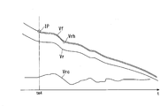
- a point (specific time point) at which the true front and rear wheel speeds Vf and Vr are considered to be the same is defined as an initial point IP.
- the true front and rear wheel speeds Vf and Vr are the same means that the front wheel speed Vf that is the basis of the vehicle speed (vehicle speed) is the same as the rear wheel speed Vr that has been corrected later.
- the front and rear wheel speeds Vf and Vr corresponding to the same vehicle speed may result in apparently different front and rear wheel speeds Vf and Vr. If the true front and rear wheel speeds Vf and Vr in consideration of the difference in the circumferential length of the front and rear tires are the same, the change rates of the wheel speeds are considered to be the same. Therefore, by correcting the front wheel speed Vf, a corrected wheel speed Vrh that can match the front wheel speed Vf is obtained, and the difference between the corrected wheel speed Vrh and the front wheel speed Vf is used for slip determination.
- the rear wheel speed change rate Vrc (t) at each measurement point of the wheel speed is obtained by the following equation 1.
- Rear wheel speed change rate Vrc (t) (Vr (t ⁇ ) ⁇ Vr (t)) / Vr (t) Equation 1 (Vr (t) is the rear wheel speed Vr at each measurement time)
- Time ⁇ is a measurement cycle.
- the timing tm4 at the moment when the vehicle is in a deceleration state and the tire rotation of the front and rear wheels 2 and 12 is stabilized is used as the initial point IP.
- This timing tm4 is a timing at which, for example, a time ⁇ of about 80 to 100 msec has elapsed after the throttle valve is turned off (fully closed). From this timing tm4, the calculation of the corrected wheel speed Vrh is started (wheel speed correction start permission).
- the initial point IP includes a condition that the vehicle body is in an upright state in the roll direction.
- the upright state includes not only an upright position where the left and right center planes of the vehicle body stand vertically, but also a range in which a change in tire circumference during determination is small (a range in which a change in tire curvature is small). For example, it includes a range where the vehicle body is at a bank angle of ⁇ 20 deg from the upright position.
- the initial point IP is detected as a state in which the motorcycle 1 is traveling stably. It should be noted that the circumferential length of the tire contact point changes during the banking of the vehicle body and an inner wheel difference occurs during cornering, so that it is not suitable for determining the front and rear wheel speed difference D.
- a ratio between the front wheel speed Vf and the corrected wheel speed Vrh is calculated as a front-rear wheel speed ratio obtained by correcting the circumferential length difference between the front and rear tires (Equation 4 below), and is used as a determination value for slipper control.
- Front / rear wheel speed ratio Vf (t) / corrected wheel speed Vrh (t) Equation 4
- the “front-rear wheel speed ratio” may be simply referred to as “wheel speed ratio”.
- the condition for allowing (starting) the slipper control during deceleration (half-clutch control) after the start of the wheel speed correction calculation is that the motorcycle 1 is in a rapid deceleration state, and during this rapid deceleration (rear grip force) ⁇ (engine brake).
- all of the following conditions must be satisfied.
- Front wheel speed Vf / corrected wheel speed Vrh (front-rear slip rate)> fourth specified value (reference is 1 (front wheel speed Vf corrected wheel speed Vrh), rear wheel slip increases as front-rear slip rate increases) 3.
- (front-rear slip amount)> first specified value K1 (reference is 0 (front wheel speed Vf corrected wheel speed Vrh), rear wheel slip increases as front-rear slip amount
- the front-rear slip ratio can be equal to or greater than the fourth specified value when (rear grip force) ⁇ (engine brake) and the front-rear wheel speed difference D occurs.
- the front-rear slip ratio is equal to or greater than the fourth specified value, a situation may be required in which slipper control intervention is required.
- the ECU 60 After the vehicle body deceleration has increased from the 0 level to the third specified value K3, if the longitudinal slip rate is at least one of the fourth specified value and the longitudinal slip amount is at least one of the first specified value K1, the ECU 60 counts a timer. To start. When the count exceeds a specified time, slipper control at the time of deceleration is started. By making the control condition continue for a prescribed time, the instantaneous slip and the like are excluded.
- ⁇ Fifth specified value (equivalent to 0, to prevent shock when clutch is engaged)
- the clutch control device 60A of the motorcycle 1 in the first embodiment includes the rear wheel 12, which is a driving wheel, the front wheel 2, which is a driven wheel, the traveling engine 13, and the engine 13 described above.
- An ECU 60 wherein the ECU 60 reduces the clutch capacity when the motorcycle 1 detects that the rear wheel 12 is in a predetermined contact load reduction state (rear lift state) during deceleration of the motorcycle 1. I do.
- the ECU 60 determines that the rear wheel speed Vr, which is the rotation speed of the rear wheel 12, is different from the front wheel speed Vf, which is the rotation speed of the front wheel 2, by a predetermined difference (first specified value K1). ), It is determined that the rear wheel 12 is in the ground contact load reduced state. According to this configuration, it is possible to perform slipper control for reducing the clutch capacity when detecting a decrease in the grounding load that causes the rear wheel 12 to float when the motorcycle 1 decelerates. Thus, it is possible to secure an appropriate engine brake during normal running with the ground load of the rear wheel 12 secured, and to shift to slipper control during rapid deceleration when the rear wheel 12 floats.
- the engine brake of the rear wheel 12 is weakened by the slipper control, the occurrence of hopping and snaking due to the engine brake when the ground load of the rear wheel 12 is released is suppressed. For this reason, it is possible to ensure the rear-wheel contact property of the motorcycle 1 during deceleration. For example, in the racing use of the motorcycle 1, when entering a corner while suddenly decelerating, the rider can easily concentrate on cornering, which can contribute to a transition to smooth acceleration when the corner rises. Further, the clutch capacity can be made variable as compared with a mechanical back torque limiter.
- the ECU 60 uses the corrected wheel speed Vrh obtained by correcting the front wheel speed Vf as the rear wheel speed Vr to be compared with the front wheel speed Vf.
- the actual front and rear wheel speeds Vf and Vr are affected not only by the difference in the tire outer diameter of the front and rear wheels 2 and 12, but also by the change in the circumferential length of the tire.
- a corrected wheel speed Vrh for comparison is calculated based on the front wheel speed Vf, and the corrected wheel speed Vrh is compared with the front wheel speed Vf, thereby being affected by a change in tire circumference. Without this, it is possible to accurately detect a decrease in the rear wheel speed Vr, and to prevent an inadvertent decrease in clutch capacity (a decrease in engine brake).
- the corrected wheel speed Vrh is obtained by adding the change amount of the rear wheel speed Vr at the same time to the front wheel speed Vf at the time of the wheel speed correction.
- the change amount of the rear wheel speed Vr is added to the front wheel speed Vf to correct the wheel speed, so that the correction control can be simplified and the system load can be suppressed.
- the motorcycle 1 In the clutch control device 60A of the motorcycle 1, it is specified that the motorcycle 1 is in the upright posture, the difference between the front and rear wheel speeds Vf and Vr is less than a predetermined predetermined initial value, and the throttle of the engine 13 is closed.
- the wheel speed correction is started from the time point (initial point IP).
- the motorcycle 1 is in the decelerating state in which the throttle of the engine 13 is closed in the upright posture, and the difference between the front and rear wheel speeds Vf and Vr is less than the initial specified value which is set in advance as a value without rear wheel slip.
- wheel speed correction can be performed with high accuracy.
- a value obtained by dividing the front wheel speed Vf by the corrected wheel speed Vrh is set as a first parameter Pa1 (front-rear slip ratio), and the corrected wheel speed is calculated from the front wheel speed Vf.
- a value obtained by subtracting Vrh is defined as a second parameter Pa2 (a longitudinal slip amount), and the slipper control is interposed according to at least one of the first parameter Pa1 and the second parameter Pa2.
- an appropriate value is selected from the two types of parameters, and the slipper control intervention determination (determination that the rear wheel 12 is slipping, in other words, slip determination) is performed, so that the necessary minimum value is obtained.
- the slipper control can be performed at a frequency of.
- the slipper control is interposed according to the first parameter Pa1, and the vehicle speed is lower than the first vehicle speed and the second vehicle speed is lower than the second vehicle speed.
- the slipper control is interposed according to the second parameter Pa2.
- the ECU 60 opens the throttle of the engine 13 in a state where the slipper control is intervened, and cancels the state where the ground contact load of the rear wheel 12 is reduced. , The intervention of the slipper control is released.
- the clutch capacity can be quickly restored from the reduced state to the connected state.
- the deceleration slipper control and the wheel speed correction control of the second embodiment are basically the same as those of the first embodiment.
- the purpose is to realize reliable slipper control intervention during deceleration.
- the second embodiment even when sudden braking of the vehicle is performed in the vehicle body bank state, reliable slipper control intervention during deceleration is realized.
- the effective circumference of the tires of the front and rear wheels 2 and 12 changes under the influence of various factors. For this reason, even when trying to detect the wheel speed, a value different from the actual wheel speed may be detected, making it difficult to detect the occurrence of the wheel speed difference.
- the effective circumference of a tire changes due to differences in default circumference due to differences in tire brand, differences in circumference due to tire wear, and differences in circumference due to tire deformation (air pressure, speed, etc.). I will. Changes in the effective circumference due to the influence of the tires are corrected by executing the wheel speed correction control described above, so that the occurrence of a wheel speed difference can be accurately detected.
- the contact angle between the road surface and the tire changes, so that the effective circumference of the tire changes.
- the wheel speed correction control also becomes difficult. That is, in a region where the bank angle is large, the difference in the change in the effective circumference of the front and rear wheel tires is large, and it is difficult to accurately detect the occurrence of the wheel speed difference.
- the vertical axis of FIG. 10C indicates a value (perimeter change rate ratio) obtained by dividing the change rate of the effective circumference of the front wheel (front wheel change rate) by the change rate of the effective circumference of the rear wheel (rear wheel change rate). .
- the effective circumference of the rear wheels becomes relatively longer as the vehicle body is banked.
- the rotational speed of the rear wheel becomes apparently higher (faster), so that the slip of the rear wheel is hardly detected, and the intervention of the slipper control may be delayed.
- the deceleration of the front wheel speed front wheel deceleration (vehicle speed If the deceleration is greater than or equal to a predetermined value, the slipper control during deceleration is permitted (started).
- a control intervention pattern at the time of sudden deceleration in a vehicle body upright state (a bank angle of less than 20 °) will be described.
- the wheel speed correction control is performed in the area a1 where the load movement of the vehicle has calmed down due to elapse of a predetermined time or the like.
- slipper control during deceleration is interposed.
- the vehicle when entering a cornering in a race or the like, even when sudden deceleration is started in the upright state of the vehicle, the vehicle may be banked to the left or right in the decelerated state (arrows a3 and a4 in the figure).
- the difference in the change in the effective circumference of the front and rear wheel tires is increased, so that the rotational speed of the rear wheel is apparently reduced, and the slipper control during deceleration is intervened earlier.
- it is possible to ensure early contact with the rear wheels when the vehicle body bank is decelerated.
- a control intervention pattern at the time of sudden deceleration in a vehicle bank state (a bank angle of 20 ° or more) will be described with reference to FIG. 11B.
- the wheel speed correction control is performed in the area b1 where the load movement of the vehicle has calmed down due to the lapse of a predetermined time or the like as described above. I do.
- slipper control during deceleration is interposed.
- ⁇ Referring to FIG. 12, even in a bank state in which the vehicle body roll angle (bank angle) is equal to or greater than a predetermined value, when the front wheel speed deceleration exceeds a predetermined value, a wheel speed correction calculation is started (timing tm5). Then, if an increase in the corrected wheel speed ratio (difference) is recognized, slipper control during deceleration is started (timing tm6). Thereafter, when the deceleration of the front wheel speed becomes less than a predetermined value (timing tm7), the calculation of the wheel speed correction and the slipper control during deceleration are ended and the clutch is engaged.
- the throttle opening starts to decrease immediately after the vehicle starts. Shifts from the acceleration state to the deceleration state (timing tm8). At this time, triggered by the closing of the throttle grip, the first timer for waiting for vehicle body stability starts counting. The count of the first timer is reset by opening the throttle grip.
- the second timer for waiting for the vehicle body stabilization starts counting when the deceleration of the vehicle speed reaches a predetermined value or more (timing). tm9). Note that the count of the second timer is reset when the deceleration of the vehicle speed falls below a predetermined value.
- the condition for starting the wheel speed correction calculation in the vehicle body bank state is that all of the following conditions are satisfied. 1. 1. Both timers expire for waiting for vehicle stability. 2. Body bank state Front wheel speed ⁇ predetermined value Front wheel speed deceleration ⁇ predetermined value The wheel speed correction calculation is started at timing tm10 (see FIG. 13) in which these conditions are satisfied.
- the wheel speed correction calculation in the vehicle body bank state ends. 1. 1. Opening the throttle grip Front wheel speed ⁇ predetermined value Front wheel speed deceleration ⁇ predetermined value At time tm11 (see FIG. 13) in which at least one of these conditions is satisfied, the wheel speed correction calculation ends. The calculation is continued even if the vehicle bank angle changes during the wheel speed correction calculation.
- the bank angle increases (deepens) and a case where the bank angle decreases (shallows) based on the bank angle at the start of the wheel speed correction.
- the bank angle becomes deep, the wheel speed ratio tends to increase, so that slipper control is easily performed, and there is no possibility that control is not intervened.
- the bank angle becomes shallow, the wheel speed ratio tends to decrease, so that it is difficult to enter the slipper control, and there is a possibility that control is not intervened.
- the intervention conditions of the slipper control at this time will be described with reference to FIG.
- the slipper control intervention condition is that at least one of the following conditions is satisfied. 1. 1. When front wheel speed ⁇ predetermined value, corrected wheel speed ratio ⁇ predetermined value When front wheel speed ⁇ predetermined value, corrected wheel speed ratio ⁇ predetermined value (for each gear) 3. Deceleration of front wheel speed according to bank angle ⁇ threshold (see FIG. 15) In the example of FIG. 14, in the vehicle body bank state, the corrected wheel speed ratio is less than the predetermined value, but slipper control is interposed at timing tm12 when the deceleration of the front wheel speed reaches the predetermined value.
- the intervention of the slipper control ends. 1. 1. Opening the throttle grip Front wheel speed deceleration ⁇ predetermined value In the example of FIG. 14, the intervention of the slipper control is ended, for example, at timing tm13 when the throttle opening operation is performed.
- FIG. 16 is a control flow when determining whether or not to shift to the wheel speed correction control in the first and second embodiments.
- this control flow whether to perform the wheel speed correction control of the first embodiment or the wheel speed correction control of the second embodiment is divided depending on the bank angle of the vehicle body.
- step S11 it is determined whether or not the vehicle body bank angle is equal to or larger than a predetermined value. If YES in step S11 (the vehicle body bank angle is equal to or more than the predetermined value), the process proceeds to step S12, and it is determined whether the wheel speed correction condition in the vehicle body bank is satisfied.
- the wheel speed correction condition in the vehicle body bank is that the vehicle speed is equal to or higher than a predetermined value, the deceleration is equal to or higher than a predetermined value, and the grip APS opening is equal to or lower than a predetermined value. If YES in step S12 (the wheel speed correction condition is satisfied), the process proceeds to step S13 to perform wheel speed correction control in the vehicle body bank (second embodiment). The wheel speed correction control itself is the same as in the first embodiment. If NO (the wheel speed correction condition is not satisfied) in step S12, the process is temporarily terminated.
- step S11 the vehicle body bank angle is less than the predetermined value
- step S14 determines whether or not the wheel speed correction condition while the vehicle is upright is satisfied.
- the wheel speed correction condition when the vehicle is standing upright is that the vehicle speed is equal to or higher than a predetermined value, the deceleration is equal to or higher than a predetermined value, the grip APS opening is equal to or lower than a predetermined value, and the wheel speed ratio is lower than a predetermined value. , Are all satisfied.
- step S14 the wheel speed correction condition is satisfied
- the process proceeds to step S15, and the wheel speed correction condition while the vehicle is standing upright is performed (first embodiment). If NO in step S14 (the wheel speed correction condition is not satisfied), the process is temporarily terminated.
- FIG. 17 is a control flow when determining whether or not the slipper control is executed in the first and second embodiments.
- the difference between the first embodiment and the second embodiment is whether or not deceleration is considered.
- step S21 it is determined whether or not the wheel speed correction control in the vehicle body bank is being performed (step S21). If YES in step S21 (during wheel speed correction control in the vehicle body bank (second embodiment)), the process shifts to step S22 to determine whether the wheel speed ratio is equal to or higher than a predetermined value. If YES in step S22 (the wheel speed ratio is equal to or more than a predetermined value), the flow shifts to step S23 to perform slipper control in the vehicle body bank. If NO in step S22 (the wheel speed ratio is less than the predetermined value), the process proceeds to step S24 to determine whether the deceleration is equal to or more than a predetermined value.
- step S24 the flow shifts to step S23 to perform slipper control in the vehicle body bank. That is, even if the wheel speed ratio is less than the predetermined value, if the deceleration is equal to or more than the predetermined value, the slipper control is interposed. If NO in step S24 (the deceleration is less than the predetermined value), the process is temporarily terminated.
- step S21 the wheel speed correction control in the vehicle body bank is not being performed
- step S25 it is determined whether the wheel speed correction control is being performed while the vehicle body is standing upright. If YES in step S25 (the wheel speed correction control is being performed while the vehicle is standing upright (first embodiment)), the process proceeds to step S26 to determine whether the wheel speed ratio is equal to or higher than a predetermined value. If YES in step S26 (the wheel speed ratio is equal to or more than a predetermined value), the flow shifts to step S27 to perform slipper control while the vehicle is standing upright. If NO in step S25 (the wheel speed correction control is not being performed while the vehicle is standing upright), and if NO in step S26 (the wheel speed ratio is less than a predetermined value), the process is temporarily terminated.
- FIG. 18 is a control flow when determining whether to end the slipper control in the first and second embodiments. In this control flow, the end condition of the slipper control is different between the first embodiment and the second embodiment.
- step S31 it is determined whether or not the slipper control end condition is satisfied.
- the slipper control termination condition is that at least one of the following conditions is satisfied: the grip APS opening is equal to or more than a predetermined value, and the deceleration is less than a predetermined value. If YES (slipper control end condition is satisfied) in step S31, the process shifts to step S32 to end the slipper control.
- step S31 slipper control end condition is not satisfied
- step S33 determines whether or not the slipper control is being performed while the vehicle is standing upright. If YES in step S33 (during slipper control while the vehicle is standing upright (first embodiment)), the process proceeds to step S34 to determine whether the wheel speed ratio is less than a predetermined value. If YES in step S34 (the wheel speed ratio is less than the predetermined value), the process shifts to step S32 to end the slipper control.
- step S33 the slipper control is not being performed while the vehicle is standing upright (including the second embodiment)
- step S34 the wheel speed ratio is equal to or higher than a predetermined value
- the process is temporarily terminated.
- the second embodiment since the second embodiment includes the execution of the wheel speed correction control in the vehicle body bank, the second embodiment has fewer conditions for ending the slipper control than the first embodiment, Is difficult to finish.
- the clutch control device for the motorcycle 1 when the bank angle of the vehicle body is larger than a predetermined value and the deceleration of the vehicle speed is larger than a predetermined value, the front-rear wheel speed difference is smaller than a predetermined value.
- slipper control during deceleration is intervened. That is, in a region where the bank angle of the vehicle body is large, it is difficult to accurately detect a difference in wheel speed due to different cross-sectional shapes of the tread surfaces of the front and rear wheels.
- the clutch slipper control is performed regardless of the wheel speed difference. As a result, the slipper control is appropriately shifted even when the vehicle is banked, so that the rear-wheel contact property of the motorcycle 1 at the time of deceleration can be ensured.
- the present invention is not limited to the above-described embodiment.
- the operation state of the suspension is detected by a sensor, or the body state is detected by a gyro sensor 49, so that the rear wheel is detected.
- a decrease in the ground contact load of No. 12 may be detected.
- the decrease in the ground contact load of the rear wheel 12 may be detected or the slipper control intervention determination may be performed using the actually measured rear wheel speed Vr.
- the above-mentioned saddle-ride type vehicles include all types of vehicles on which a driver rides across a vehicle body, and include not only motorcycles (including motor-driven bicycles and scooter-type vehicles) but also three wheels (besides one front wheel and two rear wheels). , Including front two-wheel and rear one-wheel vehicles) or four-wheel vehicles and including an electric motor in the prime mover, a vehicle that drives the rear wheels (drive wheels) without a transmission through control of the prime mover, etc. Is also included.
- the configuration in the above embodiment is an example of the present invention, and various changes can be made without departing from the gist of the present invention, such as replacing the component of the embodiment with a known component.
Landscapes
- Engineering & Computer Science (AREA)
- General Engineering & Computer Science (AREA)
- Physics & Mathematics (AREA)
- Fluid Mechanics (AREA)
- Mechanical Engineering (AREA)
- Hydraulic Clutches, Magnetic Clutches, Fluid Clutches, And Fluid Joints (AREA)
- Control Of Vehicle Engines Or Engines For Specific Uses (AREA)
Abstract
この鞍乗り型車両のクラッチ制御装置は、駆動輪である後輪(12)と、従動輪である前輪(2)と、走行用の原動機(13)と、前記原動機(13)と前記後輪(12)との間の動力伝達を断接するクラッチ装置(26)と、前記クラッチ装置(26)を駆動してクラッチ容量を変更するクラッチアクチュエータ(50)と、前記クラッチ容量の制御目標値(目標油圧)を演算する制御部(60)と、を備え、前記制御部(60)は、鞍乗り型車両(1)の減速時に、前記後輪(12)が予め定めた接地荷重低下状態にあることを検知した場合に、前記クラッチ容量を低減するスリッパー制御を行う。
Description
本発明は、鞍乗り型車両のクラッチ制御装置に関する。
本願は、2018年6月29日に、日本に出願された特願2018-123814号、及び2018年10月30日に、日本に出願された特願2018-204514号に基づき優先権を主張し、その内容をここに援用する。
本願は、2018年6月29日に、日本に出願された特願2018-123814号、及び2018年10月30日に、日本に出願された特願2018-204514号に基づき優先権を主張し、その内容をここに援用する。
自動二輪車等の鞍乗り型車両において、原動機と駆動輪との間の動力伝達を断接するクラッチ装置にバックトルクリミッターを備えることがある。バックトルクリミッターは、原動機の抵抗により駆動輪に作用するエンジンブレーキ(原動機に電気モータを含む場合の回生ブレーキを含む)を制限するための機構である。バックトルクリミッターは、クラッチ装置に設けたカム機構に規定以上のバックトルクが作用すると、クラッチ容量を機械的に低下させる。バックトルクとは、車両減速時に駆動輪からの駆動力によりエンジンが回されるトルクである。
クラッチ装置は、バックトルクリミッターの作動により、上記バックトルクを逃がし、駆動輪に過大なエンジンブレーキが加わることを防止する。一方、適度なエンジンブレーキを確保するために、上記バックトルクは規定以上に設定されている。上記バックトルクは、駆動輪が接地し、かつ十分にグリップした状態(十分に接地荷重を有する状態)において、上記規定以上になり得る。
特に、レースでのコーナーリング進入時のように、走行状態から急制動を行う状況では、駆動輪である後輪の接地荷重が過小になり、さらには後輪が路面から浮くことがある。後輪のグリップが失われると、エンジンブレーキがかかった際に後輪が急減速してしまう。この急減速した後輪が路面に対して速度差をもって再接地すると、後輪が小刻みに跳ね上げられる現象(ホッピング)が生じたり、速度差のある後輪がスリップして車体が左右に振れる現象(スネーキング)が生じる。
これらホッピングおよびスネーキングといった、後輪の接地性(後輪接地性)の低下に伴う車体挙動は、鞍乗り型車両のコーナー進入時に発生しやすい。この場合、ライダーは、車体挙動のコントロール(後輪接地性の回復)に注力するため、コーナー立ち上がり時の加速に影響が生じる。特にレース走行ではコーナー進入の機会が多く、かつ減速に要する時間の比率が高いので、減速時の車体安定性は重要な課題である。
クラッチ装置は、バックトルクリミッターの作動により、上記バックトルクを逃がし、駆動輪に過大なエンジンブレーキが加わることを防止する。一方、適度なエンジンブレーキを確保するために、上記バックトルクは規定以上に設定されている。上記バックトルクは、駆動輪が接地し、かつ十分にグリップした状態(十分に接地荷重を有する状態)において、上記規定以上になり得る。
特に、レースでのコーナーリング進入時のように、走行状態から急制動を行う状況では、駆動輪である後輪の接地荷重が過小になり、さらには後輪が路面から浮くことがある。後輪のグリップが失われると、エンジンブレーキがかかった際に後輪が急減速してしまう。この急減速した後輪が路面に対して速度差をもって再接地すると、後輪が小刻みに跳ね上げられる現象(ホッピング)が生じたり、速度差のある後輪がスリップして車体が左右に振れる現象(スネーキング)が生じる。
これらホッピングおよびスネーキングといった、後輪の接地性(後輪接地性)の低下に伴う車体挙動は、鞍乗り型車両のコーナー進入時に発生しやすい。この場合、ライダーは、車体挙動のコントロール(後輪接地性の回復)に注力するため、コーナー立ち上がり時の加速に影響が生じる。特にレース走行ではコーナー進入の機会が多く、かつ減速に要する時間の比率が高いので、減速時の車体安定性は重要な課題である。
ところで、近年の鞍乗り型車両において、クラッチ装置の断接操作を電気制御により自動で行うようにした自動クラッチシステムが提案されている。
このようなシステムにおける急制動時の後輪接地性を確保する手法として、例えば特許文献1には、スロットルバルブが全閉位置にあり、前輪ブレーキ油圧が一定範囲内にあることを条件にして、クラッチ容量を低下させ、エンジンブレーキが過大となることを防止する技術が開示されている。これにより、急制動時、エンジンブレーキによる後輪接地性の低下が抑えられる。
このようなシステムにおける急制動時の後輪接地性を確保する手法として、例えば特許文献1には、スロットルバルブが全閉位置にあり、前輪ブレーキ油圧が一定範囲内にあることを条件にして、クラッチ容量を低下させ、エンジンブレーキが過大となることを防止する技術が開示されている。これにより、急制動時、エンジンブレーキによる後輪接地性の低下が抑えられる。
しかし、上記従来の技術においては、後輪が浮いたか否か(後輪の接地荷重が低下したか否か)を判定してクラッチ容量を低下させるわけではないので、不用意にエンジンブレーキが低下してしまう可能性がある。
本発明は、後輪の接地荷重の低下時にも、適切なエンジンブレーキを確保しつつ、後輪接地性を確保することができる、鞍乗り型車両のクラッチ制御装置を提供することを目的とする。
上記課題の解決手段として、本発明の態様は以下の構成を有する。
(1)本発明の態様に係る鞍乗り型車両のクラッチ制御装置は、駆動輪である後輪と、従動輪である前輪と、走行用の原動機と、前記原動機と前記後輪との間の動力伝達を断接するクラッチ装置と、前記クラッチ装置を駆動してクラッチ容量を変更するクラッチアクチュエータと、前記クラッチ容量の制御目標値を演算する制御部と、を備え、前記制御部は、鞍乗り型車両の減速時に、前記後輪が予め定めた接地荷重低下状態にあることを検知した場合に、前記クラッチ容量を低減するスリッパー制御を行う。
(1)本発明の態様に係る鞍乗り型車両のクラッチ制御装置は、駆動輪である後輪と、従動輪である前輪と、走行用の原動機と、前記原動機と前記後輪との間の動力伝達を断接するクラッチ装置と、前記クラッチ装置を駆動してクラッチ容量を変更するクラッチアクチュエータと、前記クラッチ容量の制御目標値を演算する制御部と、を備え、前記制御部は、鞍乗り型車両の減速時に、前記後輪が予め定めた接地荷重低下状態にあることを検知した場合に、前記クラッチ容量を低減するスリッパー制御を行う。
(2)上記(1)に記載の鞍乗り型車両のクラッチ制御装置では、前記制御部は、前記後輪の回転速度である後車輪速が、前記前輪の回転速度である前車輪速に比して、予め定めた差分を越えて低くなったことに基づき、前記後輪が前記接地荷重低下状態にあると判断してもよい。
(3)上記(2)に記載の鞍乗り型車両のクラッチ制御装置では、前記制御部は、前記前車輪速と比較する前記後車輪速として、前記前車輪速を補正して得られる補正後車輪速を用いてもよい。
(4)上記(3)に記載の鞍乗り型車両のクラッチ制御装置では、前記補正後車輪速は、車輪速補正の時点の前記前車輪速に、同時点の前記後車輪速の変化量を加算して得られてもよい。
(5)上記(3)又は(4)に記載の鞍乗り型車両のクラッチ制御装置では、前記鞍乗り型車両が直立姿勢であり、前記前後車輪速の差が予め定めた規定値未満であり、前記原動機のスロットルが閉じている特定時点から、車輪速補正を開始してもよい。
(6)上記(3)から(5)の何れか一項に記載の鞍乗り型車両のクラッチ制御装置では、前記前車輪速を前記補正後車輪速で除した値を第一パラメータとし、前記前車輪速から前記補正後車輪速を減じた値を第二パラメータとし、前記第一パラメータおよび前記第二パラメータの少なくとも一方に応じて、前記スリッパー制御を介入させてもよい。
(7)上記(6)に記載の鞍乗り型車両のクラッチ制御装置では、車両速度が第1車両速度以上のとき、前記第一パラメータに応じて前記スリッパー制御を介入させ、車両速度が前記第1車両速度未満かつ第2車両速度以上のとき、前記第二パラメータに応じて前記スリッパー制御を介入させてもよい。
(8)上記(7)に記載の鞍乗り型車両のクラッチ制御装置では、前記車両速度が前記第2車両速度未満のとき、前記スリッパー制御を非介入としてもよい。
(9)上記(1)から(8)の何れか一項に記載の鞍乗り型車両のクラッチ制御装置では、前記制御部は、前記スリッパー制御を介入させた状態で、前記原動機のスロットルが開いたこと、および前記後輪の前記接地荷重低下状態が解消したこと、の少なくとも一方に応じて、前記スリッパー制御の介入を解除してもよい。
(10)上記(1)に記載の鞍乗り型車両のクラッチ制御装置では、車体のバンク角が所定値より大きい場合で、かつ車両速度の減速度が所定値より大きい場合には、前記クラッチ容量を低減する前記スリッパー制御を行ってもよい。
本発明の上記(1)に記載の鞍乗り型車両のクラッチ制御装置によれば、鞍乗り型車両の減速時に後輪が浮くほどの接地荷重の低下を検知した場合に、クラッチ容量を低減するスリッパー制御を行うことが可能となる。これにより、後輪の接地荷重を確保した通常走行時には、適切なエンジンブレーキを確保し、後輪が浮くような急減速時には、スリッパー制御に移行することが可能となる。このスリッパー制御により、後輪のエンジンブレーキが弱まるので、後輪の接地荷重が抜けた状態でのエンジンブレーキによるホッピングおよびスネーキングの発生が抑えられる。このため、鞍乗り型車両の減速時の後輪接地性を確保することができる。例えば、鞍乗り型車両のレーシングユースにおいて、急減速しながらコーナーへ進入する際に、ライダーがコーナーリングに集中しやすくなり、コーナー立ち上がり時の円滑な加速への移行に貢献できる。また、機械式のバックトルクリミッターに比べて、クラッチ容量を可変とすることができる。
本発明の上記(2)に記載の鞍乗り型車両のクラッチ制御装置によれば、前車輪速に比して後車輪速が低下したことにより、後輪の接地荷重が抜けた状態にあることを簡易かつ確実に判断することができる。
本発明の上記(3)に記載の鞍乗り型車両のクラッチ制御装置によれば、実際の前後車輪速は、前後輪のタイヤ外径の相違のみならず、タイヤの周長変化の影響を受ける。タイヤの周長変化は、例えばタイヤの銘柄、摩耗、遠心力による膨張、等に起因して生じる。このため、前後輪が路面に対してスリップすることなく回転していても、タイヤの周長変化に伴い前後車輪速に相違が生じることがある。
これに対し、前車輪速を基に比較用の補正後車輪速を算出し、この補正後車輪速と前車輪速とを比較することで、タイヤの周長変化の影響を受けることなく、後車輪速の低下を精度よく検知でき、不用意なクラッチ容量低下(エンジンブレーキ低下)を抑止できる。
これに対し、前車輪速を基に比較用の補正後車輪速を算出し、この補正後車輪速と前車輪速とを比較することで、タイヤの周長変化の影響を受けることなく、後車輪速の低下を精度よく検知でき、不用意なクラッチ容量低下(エンジンブレーキ低下)を抑止できる。
本発明の上記(4)に記載の鞍乗り型車両のクラッチ制御装置によれば、前車輪速に後車輪速の変化量を加算して車輪速を補正するので、補正制御を簡単にしてシステム負荷を抑えることができる。
本発明の上記(5)に記載の鞍乗り型車両のクラッチ制御装置によれば、鞍乗り型車両が直立姿勢で原動機のスロットルが閉じた減速状態であり、かつ前後車輪速の差が後輪スリップのない値として予め定めた規定値未満である状態を、車輪速補正の開始基準とすることで、車輪速補正を精度よく行うことができる。
本発明の上記(6)に記載の鞍乗り型車両のクラッチ制御装置によれば、二種類のパラメータから適切な値を選定してスリッパー制御の介入判断(後輪がスリップしているとの判断、換言すればスリップ判定)を行うことで、必要最小限の頻度でスリッパー制御を行うことができる。
本発明の上記(7)に記載の鞍乗り型車両のクラッチ制御装置によれば、車両速度に応じて適切なパラメータを選定してスリップ判定を行うことができる。
本発明の上記(8)に記載の鞍乗り型車両のクラッチ制御装置によれば、車両速度が低いときはスリッパー制御を非介入とすることで、システム負荷を抑えることができる。
本発明の上記(9)に記載の鞍乗り型車両のクラッチ制御装置によれば、鞍乗り型車両が加速に移行したこと、および後輪の接地荷重の低下が解消したこと、の少なくとも一方に応じて(換言すれば、車両状態が安定したことに応じて)、スリッパー制御を解除することで、クラッチ容量を低減状態から接続状態へ素早く回復させることができる。
本発明の上記(10)に記載の鞍乗り型車両のクラッチ制御装置によれば、車体のバンク角が大きい領域では、前後輪のトレッド面のパターンが異なる等の理由から、正確な車輪速差の検出が難しいため、車体のバンク角が所定値以上の場合には、車輪速差によらずにクラッチのスリッパー制御を行う。これにより、車体バンク時にも適切にスリッパー制御に移行することができる。
以下、本発明の第一実施形態について図面を参照して説明する。なお、以下の説明における前後左右等の向きは、特に記載が無ければ以下に説明する車両における向きと同一とする。また以下の説明に用いる図中適所には、車両前方を示す矢印FR、車両左方を示す矢印LH、車両上方を示す矢印UPが示されている。
<車両全体>
図1に示すように、本第一実施形態は、鞍乗り型車両の一例としての自動二輪車1に適用されている。自動二輪車1の前輪2は、左右一対のフロントフォーク3の下端部に支持されている。左右フロントフォーク3の上部は、ステアリングステム4を介して、車体フレーム5の前端部のヘッドパイプ6に支持されている。ステアリングステム4のトップブリッジ上には、バータイプの操向ハンドル4aが取り付けられている。
図1に示すように、本第一実施形態は、鞍乗り型車両の一例としての自動二輪車1に適用されている。自動二輪車1の前輪2は、左右一対のフロントフォーク3の下端部に支持されている。左右フロントフォーク3の上部は、ステアリングステム4を介して、車体フレーム5の前端部のヘッドパイプ6に支持されている。ステアリングステム4のトップブリッジ上には、バータイプの操向ハンドル4aが取り付けられている。
車体フレーム5は、ヘッドパイプ6と、ヘッドパイプ6から車幅方向(左右方向)中央を下後方へ延びるメインチューブ7と、メインチューブ7の後端部の下方に連なる左右ピボットフレーム8と、メインチューブ7および左右ピボットフレーム8の後方に連なるシートフレーム9と、を備えている。左右ピボットフレーム8には、スイングアーム11の前端部が揺動可能に枢支されている。スイングアーム11の後端部には、自動二輪車1の後輪12が支持されている。
左右メインチューブ7の上方には、燃料タンク18が支持されている。燃料タンク18の後方でシートフレーム9の上方には、前シート19および後シートカバー19aが前後に並んで支持されている。シートフレーム9の周囲は、リヤカウル9aに覆われている。左右メインチューブ7の下方には、自動二輪車1の原動機であるパワーユニットPUが懸架されている。パワーユニットPUは、後輪12と例えばチェーン式伝動機構を介して連係されている。
パワーユニットPUは、その前側に位置するエンジン(内燃機関、原動機)13と後側に位置する変速機21とを一体に有している。エンジン13は、例えばクランクシャフト14の回転軸を左右方向(車幅方向)に沿わせた複数気筒エンジンである。エンジン13は、クランクケース15の前部上方にシリンダ16を起立させている。クランクケース15の後部は、変速機21を収容する変速機ケース17とされている。
<変速機>
図2に示すように、変速機21は、メインシャフト22およびカウンタシャフト23ならびに両シャフト22,23に跨る変速ギア群24を有する有段式のトランスミッションである。カウンタシャフト23は変速機21ひいてはパワーユニットPUの出力軸を構成している。カウンタシャフト23の端部はクランクケース15の後部左側に突出し、上記チェーン式伝動機構を介して後輪12に連結されている。
図2に示すように、変速機21は、メインシャフト22およびカウンタシャフト23ならびに両シャフト22,23に跨る変速ギア群24を有する有段式のトランスミッションである。カウンタシャフト23は変速機21ひいてはパワーユニットPUの出力軸を構成している。カウンタシャフト23の端部はクランクケース15の後部左側に突出し、上記チェーン式伝動機構を介して後輪12に連結されている。
変速ギア群24は、両シャフト22,23にそれぞれ支持された変速段数分のギアを有する。変速機21は、両シャフト22,23間で変速ギア群24の対応するギア対同士が常に噛み合った常時噛み合い式とされる。両シャフト22,23に支持された複数のギアは、対応するシャフトに対して回転可能なフリーギアと、対応するシャフトにスプライン嵌合するスライドギア(シフター)とに分類される。これらフリーギア及びスライドギアの一方には軸方向で凸のドグが、他方にはドグを係合させるべく軸方向で凹のスロットがそれぞれ設けられている。すなわち、変速機21は、いわゆるドグミッションである。
変速機21のメインシャフト22及びカウンタシャフト23は、クランクシャフト14の後方で前後に並んで配置されている。メインシャフト22の右端部には、クラッチアクチュエータ50(図3参照)により作動するクラッチ装置26が同軸配置されている。クラッチ装置26は、例えば湿式多板クラッチであり、いわゆるノーマルオープンクラッチである。すなわち、クラッチ装置26は、クラッチアクチュエータ50からの油圧供給によって動力伝達可能な接続状態となり、クラッチアクチュエータ50からの油圧供給がなくなると動力伝達不能な切断状態に戻る。
クランクシャフト14の回転動力は、クラッチ装置26を介してメインシャフト22に伝達され、メインシャフト22から変速ギア群24の任意のギア対を介してカウンタシャフト23に伝達される。カウンタシャフト23におけるクランクケース15の後部左側に突出した左端部には、上記チェーン式伝動機構のドライブスプロケット27が取り付けられている。
クラッチ装置26は、不図示のバックトルクリミッターを備えている。バックトルクリミッターは、クラッチ装置26に設けたカム機構に規定以上のバックトルクが作用すると、クラッチ容量を機械的に低下させる。
クラッチ装置26は、不図示のバックトルクリミッターを備えている。バックトルクリミッターは、クラッチ装置26に設けたカム機構に規定以上のバックトルクが作用すると、クラッチ容量を機械的に低下させる。
変速機21の後上方には、変速ギア群24のギア対を切り替えるチェンジ機構25が収容されている。チェンジ機構25は、両シャフト22,23と平行な中空円筒状のシフトドラム36の回転により、その外周に形成されたリード溝のパターンに応じて複数のシフトフォーク36aを作動させ、変速ギア群24における両シャフト22,23間の動力伝達に用いるギア対を切り替える。
チェンジ機構25は、シフトドラム36と平行なシフトスピンドル31を有している。シフトスピンドル31の回転時には、シフトスピンドル31に固定されたシフトアーム31aがシフトドラム36を回転させ、リード溝のパターンに応じてシフトフォーク36aを軸方向移動させて、変速ギア群24の内の動力伝達可能なギア対を切り替える(すなわち、変速段を切り替える。)。
図1を併せて参照し、シフトスピンドル31は、チェンジ機構25を操作可能とするべくクランクケース15の車幅方向外側(左方)に軸外側部31bを突出させている。シフトスピンドル31の軸外側部31bには、シフト荷重センサ42(シフト操作検知手段)が同軸に取り付けられている。シフトスピンドル31の軸外側部31b(またはシフト荷重センサ42の回転軸)には、揺動レバー33が取り付けられている。揺動レバー33は、シフトスピンドル31(または回転軸)にクランプ固定される基端部33aから後方へ延び、その先端部33bには、リンクロッド34の上端部が上ボールジョイント34aを介して揺動自在に連結されている。リンクロッド34の下端部は、運転者が足操作するシフトペダル32に、下ボールジョイント(不図示)を介して揺動自在に連結されている。
図1に示すように、シフトペダル32は、その前端部がクランクケース15の下部に左右方向に沿う軸を介して上下揺動可能に支持されている。シフトペダル32の後端部には、ステップ32aに載せた運転者の足先を掛けるペダル部が設けられ、シフトペダル32の前後中間部には、リンクロッド34の下端部が連結されている。
ここで、自動二輪車1は、変速機21の変速操作(シフトペダル32の足操作)のみを運転者が行い、クラッチ装置26の断接操作はシフトペダル32の操作に応じて電気制御により自動で行うようにした、いわゆるセミオートマチックの変速システム(自動クラッチ式変速システム)を採用している。
<変速システム>
図4に示すように、上記変速システムは、クラッチアクチュエータ50、ECU60(Electronic Control Unit、制御部)および各種センサ41~45を備えている。
ECU60は、シフトドラム36の回転角から変速段を検知するギアポジションセンサ41、およびシフトスピンドル31に入力された操作トルクを検知するシフト荷重センサ42(例えばトルクセンサ)からの検知情報、ならびにスロットル開度センサ43、車速センサ44およびエンジン回転数センサ45等からの各種の車両状態検知情報等に基づいて、クラッチアクチュエータ50を作動制御するとともに、点火装置46および燃料噴射装置47を作動制御する。
車速センサ44は、前輪2の回転速度を検出する前車輪速センサ44fと、後輪12の回転速度を検出する後車輪速センサ44rと、を備えている。エンジン回転数は、スロットルバルブ及びアクセルグリップを含むスロットルバイワイヤ(throttle by wire:TBW)により制御される。
図4に示すように、上記変速システムは、クラッチアクチュエータ50、ECU60(Electronic Control Unit、制御部)および各種センサ41~45を備えている。
ECU60は、シフトドラム36の回転角から変速段を検知するギアポジションセンサ41、およびシフトスピンドル31に入力された操作トルクを検知するシフト荷重センサ42(例えばトルクセンサ)からの検知情報、ならびにスロットル開度センサ43、車速センサ44およびエンジン回転数センサ45等からの各種の車両状態検知情報等に基づいて、クラッチアクチュエータ50を作動制御するとともに、点火装置46および燃料噴射装置47を作動制御する。
車速センサ44は、前輪2の回転速度を検出する前車輪速センサ44fと、後輪12の回転速度を検出する後車輪速センサ44rと、を備えている。エンジン回転数は、スロットルバルブ及びアクセルグリップを含むスロットルバイワイヤ(throttle by wire:TBW)により制御される。
ECU60には、後述する油圧センサ57,58、シフト操作検知スイッチ(シフトニュートラルスイッチ)48、および車体の状況(動き)を検出するジャイロセンサ49からの検知情報も入力される。ジャイロセンサ49は、IMU(inertial measurement unit:慣性計測装置)であり、検知方向の加速度成分に応じた信号をECU60に出力する。ジャイロセンサ49は、ECU60に内蔵されてもよい。
また、ECU60は、油圧制御部61と、車輪速差判定部(リアリフト検知部)62と、を備えている。油圧制御部61、は、スリッパー制御部61aを備えている。車輪速差判定部62は、車輪速補正部62aを備えている。図中符号60Aは本第一実施形態のクラッチ制御装置を示している。
また、ECU60は、油圧制御部61と、車輪速差判定部(リアリフト検知部)62と、を備えている。油圧制御部61、は、スリッパー制御部61aを備えている。車輪速差判定部62は、車輪速補正部62aを備えている。図中符号60Aは本第一実施形態のクラッチ制御装置を示している。
図3を併せて参照し、クラッチアクチュエータ50は、ECU60により作動制御されることで、クラッチ装置26を断接する液圧を制御可能とする。クラッチアクチュエータ50は、駆動源としての電気モータ52(以下、単にモータ52という。)と、モータ52により駆動されるマスターシリンダ51と、を備えている。クラッチアクチュエータ50は、マスターシリンダ51および油圧給排ポート50pの間に設けられる油圧回路装置53とともに、一体のクラッチ制御ユニット50Aを構成している。
ECU60は、予め設定された演算プログラムに基づいて、クラッチ装置26を断接するためにスレーブシリンダ28に供給する油圧の目標値(目標油圧)を演算し、下流側油圧センサ58で検出されるスレーブシリンダ28側の油圧(スレーブ油圧)が目標油圧に近づくように、クラッチ制御ユニット50Aを制御する。
ECU60は、予め設定された演算プログラムに基づいて、クラッチ装置26を断接するためにスレーブシリンダ28に供給する油圧の目標値(目標油圧)を演算し、下流側油圧センサ58で検出されるスレーブシリンダ28側の油圧(スレーブ油圧)が目標油圧に近づくように、クラッチ制御ユニット50Aを制御する。
マスターシリンダ51は、シリンダ本体51a内のピストン51bをモータ52の駆動によりストロークさせて、シリンダ本体51a内の作動油をスレーブシリンダ28に対して給排可能とする。図中符号55はボールネジ機構としての変換機構、符号54はモータ52および変換機構55に跨る伝達機構、符号51eはマスターシリンダ51に接続されるリザーバをそれぞれ示す。
油圧回路装置53は、マスターシリンダ51からクラッチ装置26側(スレーブシリンダ28側)へ延びる主油路(油圧給排油路)53mの中間部位を開通又は遮断するバルブ機構(ソレノイドバルブ56)を有している。油圧回路装置53の主油路53mは、ソレノイドバルブ56よりもマスターシリンダ51側となる上流側油路53aと、ソレノイドバルブ56よりもスレーブシリンダ28側となる下流側油路53bと、に分けられる。油圧回路装置53はさらに、ソレノイドバルブ56を迂回して上流側油路53aと下流側油路53bとを連通するバイパス油路53cを備えている。
ソレノイドバルブ56は、いわゆるノーマルオープンバルブである。バイパス油路53cには、上流側から下流側への方向のみ作動油を流通させるワンウェイバルブ53c1が設けられている。ソレノイドバルブ56の上流側には、上流側油路53aの油圧を検出する上流側油圧センサ57が設けられている。ソレノイドバルブ56の下流側には、下流側油路53bの油圧を検出する下流側油圧センサ58が設けられている。
図1に示すように、クラッチ制御ユニット50Aは、例えばリヤカウル9a内に収容されている。スレーブシリンダ28は、クランクケース15の後部左側に取り付けられている。クラッチ制御ユニット50Aとスレーブシリンダ28とは、油圧配管53e(図3参照)を介して接続されている。
図2に示すように、スレーブシリンダ28は、メインシャフト22の左方に同軸配置されている。スレーブシリンダ28は、クラッチアクチュエータ50からの油圧供給時には、メインシャフト22内を貫通するプッシュロッド28aを右方へ押圧する。スレーブシリンダ28は、プッシュロッド28aを右方へ押圧することで、該プッシュロッド28aを介してクラッチ装置26を接続状態へ作動させる。スレーブシリンダ28は、油圧供給が無くなると、プッシュロッド28aの押圧を解除し、クラッチ装置26を切断状態に戻す。
クラッチ装置26を接続状態に維持するには油圧供給を継続する必要があるが、その分だけ電力を消費することとなる。そこで、図3に示すように、クラッチ制御ユニット50Aの油圧回路装置53にソレノイドバルブ56を設け、クラッチ装置26側への油圧供給後にソレノイドバルブ56を閉じている。これにより、クラッチ装置26側への供給油圧を維持し、圧力低下分だけ油圧を補う(リーク分だけリチャージする)構成として、エネルギー消費を抑えている。
<クラッチ制御モード>
図5に示すように、本第一実施形態のクラッチ制御装置60Aは、三種のクラッチ制御モードを有している。クラッチ制御モードは、自動制御を行うオートモードM1、手動操作を行うマニュアルモードM2、および一時的な手動操作を行うマニュアル介入モードM3、の三種のモード間で、クラッチ制御モード切替スイッチ59(図4参照)およびクラッチレバー4b(図1参照)の操作に応じて適宜遷移する。なお、マニュアルモードM2およびマニュアル介入モードM3を含む対象をマニュアル系M2Aという。クラッチ制御装置60Aは、クラッチレバー4bとクラッチ装置26とを電気的に接続したクラッチバイワイヤシステムとしても機能する。
図5に示すように、本第一実施形態のクラッチ制御装置60Aは、三種のクラッチ制御モードを有している。クラッチ制御モードは、自動制御を行うオートモードM1、手動操作を行うマニュアルモードM2、および一時的な手動操作を行うマニュアル介入モードM3、の三種のモード間で、クラッチ制御モード切替スイッチ59(図4参照)およびクラッチレバー4b(図1参照)の操作に応じて適宜遷移する。なお、マニュアルモードM2およびマニュアル介入モードM3を含む対象をマニュアル系M2Aという。クラッチ制御装置60Aは、クラッチレバー4bとクラッチ装置26とを電気的に接続したクラッチバイワイヤシステムとしても機能する。
オートモードM1は、自動発進・変速制御により走行状態に適したクラッチ容量を演算してクラッチ装置26を制御するモードである。マニュアルモードM2は、乗員によるクラッチ操作指示に応じてクラッチ容量を演算してクラッチ装置26を制御するモードである。マニュアル介入モードM3は、オートモードM1中に乗員からのクラッチ操作指示を受け付け、クラッチ操作指示からクラッチ容量を演算してクラッチ装置26を制御する一時的なマニュアル操作モードである。なお、マニュアル介入モードM3中に乗員がクラッチレバー4bの操作をやめる(完全にリリースする)と、オートモードM1に戻るよう設定されている。
本第一実施形態のクラッチ制御装置60Aは、エンジン13の回転駆動力で不図示のオイルポンプを駆動してクラッチ制御油圧を発生する。このため、クラッチ制御装置60Aは、システム起動時には、オートモードM1でクラッチオフの状態(切断状態)から制御を始める。また、クラッチ制御装置60Aは、エンジン13停止時にはクラッチ操作が不要なので、オートモードM1でクラッチオフに戻るよう設定されている。
オートモードM1は、クラッチ制御を自動で行うことが基本であり、レバー操作レスで自動二輪車1を走行可能とする。オートモードM1では、スロットル開度、エンジン回転数、車速およびシフトセンサ出力により、クラッチ容量をコントロールしている。これにより、自動二輪車1をスロットル操作のみでエンストすることなく発進可能であり、かつシフト操作のみで変速可能である。ただし、アイドリング相当の極低速時には自動でクラッチ装置26が切断することがある。また、オートモードM1では、クラッチレバー4bを握ることでマニュアル介入モードM3となり、クラッチ装置26を任意に切ることも可能である。
一方、マニュアルモードM2では、乗員によるレバー操作により、クラッチ容量をコントロールする。オートモードM1とマニュアルモードM2とは、停車中にクラッチ制御モード切替スイッチ59(図4参照)を操作することで切り替え可能である。なお、クラッチ制御装置60Aは、マニュアル系M2A(マニュアルモードM2又はマニュアル介入モードM3)への遷移時にレバー操作が有効であることを示すインジケータを備えてもよい。
マニュアルモードM2は、クラッチ制御を手動で行うことが基本であり、クラッチレバー4bの作動角度に応じてクラッチ油圧を制御可能である。これにより、乗員の意思のままにクラッチ装置26の断接をコントロール可能であり、かつアイドリング相当の極低速時にもクラッチ装置26を接続して走行可能である。ただし、レバー操作によってはエンストすることがあり、かつスロットル操作のみでの自動発進も不可である。なお、マニュアルモードM2であっても、シフト操作時にはクラッチ制御が自動で介入する。
オートモードM1では、クラッチアクチュエータ50により自動でクラッチ装置26の断接が行われるが、クラッチレバー4bに対するマニュアルクラッチ操作が行われることで、クラッチ装置26の自動制御に一時的に手動操作を介入させることが可能である(マニュアル介入モードM3)。
<減速時スリッパー制御>
次に、自動二輪車1の減速時スリッパー制御について説明する。
図6を参照し、自動二輪車1において、レースでのコーナー進入時等の急減速時には、リア接地荷重Mg2(後輪接地荷重)が抜ける(過小になる)ことで、前後輪2,12間に車輪速差Dが発生する。
次に、自動二輪車1の減速時スリッパー制御について説明する。
図6を参照し、自動二輪車1において、レースでのコーナー進入時等の急減速時には、リア接地荷重Mg2(後輪接地荷重)が抜ける(過小になる)ことで、前後輪2,12間に車輪速差Dが発生する。
図8を併せて参照し、自動二輪車1の急減速時には、フロント接地荷重Mg1(前輪接地荷重)が増大し、フロントグリップ力Mg3が主体の減速となる。すなわち、車体の重心Gに減速による慣性力Fb1が作用すると、この慣性力Fb1の分力Fb2がフロント接地位置Pg1を基準として前上方に向けて作用し、車体にフロント接地位置Pg1を基準としたモーメントを発生させる。これにより、リア接地荷重Mg2が抜けて(減少して)、リアグリップ力Mg4を低下させる。車体減速度の大きさによっては、リア接地荷重Mg2がゼロになり、後輪12が路面から浮く(リアグリップ力Mg4がゼロになる)。
減速中に後輪12が浮くと、エンジンブレーキの影響によって後輪12の回転速度が急減速する。後輪12が浮かなくても、リア接地荷重Mg2が希薄になってリアグリップ力Mg4が低下し、エンジンブレーキによって後輪12がスリップする。これにより、前輪2の回転速度(前車輪速Vf)に対し、後輪12の回転速度(後車輪速Vr)が低くなる。以下、後輪12が路面から浮いた状態、および前後輪2,12の車輪速差Dが生じるほどリア接地荷重Mg2が低下した状態を含んで、リアリフト状態という。
リアリフト状態によって、ホッピングおよびスネーキングといった、後輪12の接地性(後輪接地性)の低下に伴う車体挙動が生じる。リアリフト状態では、クラッチ装置26に規定以上のバックトルクは作用しない。このため、クラッチ装置26のバックトルクリミッターは作動せず、後輪接地性の低下に伴う車体挙動を解消できない。一方、エンジン13の燃料噴射およびスロットルバルブの開閉等によるエンジンブレーキ制御については、応答性および制御性に課題がある。
本第一実施形態では、レースのブレーキングに相当するような急減速時において、リアリフト状態になったか否かを判定する。そして、この判定に基づき、自動クラッチシステムの制御によりクラッチ容量を低下させる(減速時スリッパー制御)。これにより、ホッピングおよびスネーキングの発生を抑え、後輪接地性を確保する。後輪12が浮いたか否かを判定してクラッチ容量を低下させるので、従来の技術に比べて、不用意にエンジンブレーキが低下することを抑え、適切なエンジンブレーキを確保する。また、エンジン制御によるエンジンブレーキ制御に比べて、制御時の応答性および制御性がよい。
リアリフト状態か否かの判定(リア接地荷重Mg2が過小になったか否かの判定)は、ECU60の車輪速差判定部62でなされる。車輪速差判定部62は、ブレーキオン時に前後車輪速Vf,Vrの差分(前後車輪速差D)が規定以上になると、急減速によるリアリフト状態であると判定する。換言すれば、車輪速差判定部62は、ブレーキスイッチの検出信号および前後車輪速センサ44f,44rの検出信号等に基づき、急減速によるリアリフト状態であることを検知する。
車輪速差判定部62がリアリフト状態であることを検知(判定)すると、ECU60の油圧制御部61のスリッパー制御部61aにおいて、クラッチ装置26に対するスリッパー制御がなされる。スリッパー制御部61aは、予め設定された演算プログラムに基づいて、スレーブシリンダ28に供給する油圧の目標値(目標油圧)を演算し、クラッチ制御ユニット50Aを制御する。スリッパー制御とは、クラッチ装置26のクラッチ容量を下げる制御(目標油圧を低減する制御)である。
スリッパー制御は、バックトルクリミッターと同様、クラッチ装置26に滑りを発生させる。スリッパー制御は、クラッチ装置26にクラッチ差回転(クラッチスリップ)を発生させる。スリッパー制御は、クラッチ装置26に作用するバックトルクを逃がし、後輪12に作用するエンジンブレーキを抑制する。スリッパー制御は、ホッピングおよびスネーキングといった、後輪12の接地性(後輪接地性)の低下に伴う車体挙動を抑える。
図6を参照し、自動二輪車1において、両輪2,12が接地した走行状態から、後輪12がリフトするほどの急減速を行うと、後車輪速Vrが前車輪速Vfに対して傾き大で低下する。すなわち、後輪12が浮くほどの減速時には、後車輪速Vrは前車輪速Vfに比して低くなる。図6のグラフにおける前後車輪速Vf,Vrを示す線の傾きを前後輪2,12各々の減速度Af,Arとし、前後車輪速Vf,Vrの同タイミングでの差分を前後車輪速差Dとする。クラッチ装置26は、前後車輪速差Dが予め定めた第一規定値K1(差分)となるタイミングtm1になるまで、クラッチ容量を最大値に維持した締結状態にある。このとき、クラッチ装置26は、クラッチ差回転を実質的に0としたまま推移する。この急減速の途中で後輪12がリフトしている。
クラッチ装置26は、前後車輪速差Dが第一規定値K1となるタイミングtm1において、減速制御(スリッパー制御)が開始される。クラッチ装置26は、タイミングtm1以降は、クラッチ容量を低下させた状態となる。つまり、クラッチ装置26は、タイミングtm1以降は半クラッチ状態となり、スリッパー制御無しの場合(図中線Dc’)に対して、クラッチ差回転(クラッチスリップ)を発生させる(図中線Dc)。すると、スリッパー制御無しの後車輪速Vr’に対して、スリッパー制御有りの後車輪速Vrは、低下(減速度Ar)が緩やかになる。
後輪12が接地すると(タイミングtm2)、その後、スリッパー制御無しの後車輪速Vr’は大きく乱れるのに対し、スリッパー制御有りの後車輪速Vrは、クラッチスリップが許容されることから乱れが抑えられる。また、スリッパー制御無しのクラッチ差回転Dc’は乱れるのに対し、スリッパー制御有りのクラッチ差回転Dcは、増加が許容されることから乱れが抑えられる。
やがて、後車輪速Vrが前車輪速Vfに近付いていく。後車輪速Vrが前車輪速Vfに近付くと、後輪12の路面に対する速度差が小さくなり、後輪12が接地した際のホッピングおよびスネーキングが抑えられる。また、クラッチ容量が低下しているため、路面との速度差があったとしても後輪12からのバックトルクの入力が小さくなる。結果として、後輪12の接地性(後輪接地性)の低下に伴う車体挙動が抑えられる。
後輪12が接地すると(タイミングtm2)、その後、スリッパー制御無しの後車輪速Vr’は大きく乱れるのに対し、スリッパー制御有りの後車輪速Vrは、クラッチスリップが許容されることから乱れが抑えられる。また、スリッパー制御無しのクラッチ差回転Dc’は乱れるのに対し、スリッパー制御有りのクラッチ差回転Dcは、増加が許容されることから乱れが抑えられる。
やがて、後車輪速Vrが前車輪速Vfに近付いていく。後車輪速Vrが前車輪速Vfに近付くと、後輪12の路面に対する速度差が小さくなり、後輪12が接地した際のホッピングおよびスネーキングが抑えられる。また、クラッチ容量が低下しているため、路面との速度差があったとしても後輪12からのバックトルクの入力が小さくなる。結果として、後輪12の接地性(後輪接地性)の低下に伴う車体挙動が抑えられる。
スリッパー制御は、前後車輪速差Dが予め定めた第二規定値K2未満まで低下し、かつ車速の減速度(前輪2の減速度Afに基づく)が予め定めた第三規定値K3未満まで低下したタイミングtm3まで継続する。第二規定値K2は、前後車輪速差Dが0に収束すると見込まれる値である。第三規定値K3は、リアリフト状態が解消したと見込まれる値である。図6では、後輪リフトが生じた後にタイミングtm1に至り、後輪12が再接地した後にタイミングtm3に至る。
車速の減速度が低下し、かつ前後車輪速Vf,Vrの差分が0に収束しようとするタイミングtm3において、スリッパー制御が終了し、クラッチ装置26の再接続(上記締結状態とする通常制御)がなされる。クラッチ装置26の再接続によって、クラッチ差回転が吸収されて0に収束していく。すなわち、クラッチ装置26は通常の接続状態に復帰する。
スリッパー制御を行わない場合の後車輪速Vr’は、タイミングtm1を過ぎた後、スリッパー制御を行った場合の後車輪速Vrよりも前後車輪速差Dが大となる。前後車輪速差Dが大となった状態のまま、浮いた後輪12が路面に対して速度差をもって接地すると、ホッピング等の車体挙動が生じやすく(図中領域R1)、減速後の再加速に影響を与えてしまう。
本第一実施形態では、急減速時にもスリッパー制御により後輪接地性を向上させるので、減速時の車体安定性を向上させ、車体コントロール性の向上に寄与する。
機械式のバックトルクリミッターと比較して、少ないバックトルクでもクラッチスリップを発生させることが可能である。このため、後輪12の接地荷重が低い状態でも後輪接地性を向上させ、ホッピング等の発生を抑える。例えばレーシングユースにおいて、急減速しながらのコーナー進入時にも、車体挙動を安定させるので、減速後のコーナーリング中にもスロットルを開けやすく、コーナー立ち上がり時の加速の向上に貢献する。
機械式のバックトルクリミッターと比較して、少ないバックトルクでもクラッチスリップを発生させることが可能である。このため、後輪12の接地荷重が低い状態でも後輪接地性を向上させ、ホッピング等の発生を抑える。例えばレーシングユースにおいて、急減速しながらのコーナー進入時にも、車体挙動を安定させるので、減速後のコーナーリング中にもスロットルを開けやすく、コーナー立ち上がり時の加速の向上に貢献する。
図7Aを参照し、自動二輪車1の減速時には、まず、スロットルオフによりTH開度およびC軸(クランクシャフト14)トルクが低下する。その後、ブレーキスイッチON(ブレーキ操作)により車体減速度が増加し、かつ前後車輪速Vf,Vrに規定以上の差が生じることで、スリッパー制御が開始される(領域R2)。スリッパー制御により、スレーブシリンダ28に供給する油圧の目標値(目標油圧)、および実際のスレーブ油圧(制御油圧)が半クラッチ相当まで低減する。これにより、減速時のホッピング等の発生が抑制され(領域R3)、減速後のコーナーリング中にも車体挙動が安定しているので早期にスロットルを開けられ(領域R4)、車速も伸びる。図中「Ne」はエンジン回転数を示す。
図7Bを参照し、スリッパー制御を行わない場合の比較例では、減速時のC軸トルクの乱れからわかるように、ホッピング等の発生がある(領域R5)。この影響により、減速後のコーナーリング中にスロットルが開けられなくなり(領域R6)、スリッパー制御を行う場合に比べて車速の伸びが低下する。
頻繁にスリッパー制御を介入させることは、エンジンブレーキの利用、システムの負荷軽減、およびライダーの違和感の観点から好ましくない。できる限りエンジンブレーキを利かせ、かつライダーの違和感を抑えるために、スリッパー制御の介入頻度は抑えたい。つまり、実際に車輪速差が発生した後に、スリッパー制御を介入させる仕様が好ましい。
本第一実施形態では、車体姿勢、前後車輪速Vf,Vr、車体加速度(減速度)を検知し、これらの検知情報に基づきクラッチ容量を制御する仕様とした。
本第一実施形態では、車体姿勢、前後車輪速Vf,Vr、車体加速度(減速度)を検知し、これらの検知情報に基づきクラッチ容量を制御する仕様とした。
例えば、減速時スリッパー制御の介入条件は、下記条件が全て成立することとした。
第一に、車体減速度(絶対値)が第三規定値K3以上(例えば単位時間当たりの車速変動が現車速の1%以上となるよう設定)であることを条件とする。これにより、後輪12が浮くような急減速時であることを検知する。一方、バンク状態および単なるリアロック状態は排除する。
第二に、前後スリップ率(前車輪速Vf/後車輪速Vr)が予め定めた第四規定値以上であることを条件とする。
第三に、前後スリップ量(前車輪速Vf-後車輪速Vr)が第一規定値K1以上であることを条件とする。
つまり、前後スリップ量(前後車輪速差D)が第一規定値K1以上であることに加え、前後スリップ率が第四規定値以上であることも条件に加えた。これら二種類のパラメータを用いてスリッパー制御の介入判断(後輪12がスリップしているとの判断、換言すればスリップ判定)を行うことで、後輪12が浮いたことをより精度よく判断できる。
第一に、車体減速度(絶対値)が第三規定値K3以上(例えば単位時間当たりの車速変動が現車速の1%以上となるよう設定)であることを条件とする。これにより、後輪12が浮くような急減速時であることを検知する。一方、バンク状態および単なるリアロック状態は排除する。
第二に、前後スリップ率(前車輪速Vf/後車輪速Vr)が予め定めた第四規定値以上であることを条件とする。
第三に、前後スリップ量(前車輪速Vf-後車輪速Vr)が第一規定値K1以上であることを条件とする。
つまり、前後スリップ量(前後車輪速差D)が第一規定値K1以上であることに加え、前後スリップ率が第四規定値以上であることも条件に加えた。これら二種類のパラメータを用いてスリッパー制御の介入判断(後輪12がスリップしているとの判断、換言すればスリップ判定)を行うことで、後輪12が浮いたことをより精度よく判断できる。
前後スリップ率および前後スリップ量の一方に応じて、スリップ判定を行う構成でもよい。すなわち、前後スリップ率および前後スリップ量の少なくとも一方に応じて、スリップ判定を行う構成でもよい。以下、前後スリップ率を第一パラメータPa1、前後スリップ量を第二パラメータPa2ということがある。
前後スリップ率および前後スリップ量の何れがスリップ判定に適しているかについて、本出願人が鋭意検討した結果、車両速度(車速)が高いときは前後スリップ率が、車両速度(車速)が低いときは前後スリップ量が、それぞれスリッパー制御の介入判断に適しているとの知見を得た。
例えば、車両速度が第1車両速度(例えば70km/h)以上のときは、前後スリップ率に応じてスリッパー制御を介入させる構成とした。また、車両速度が第1車両速度未満かつ第2車両速度(例えば50km/h)以上のときは、前後スリップ量に応じてスリッパー制御を介入させる構成とした。
例えば、車両速度が第1車両速度(例えば70km/h)以上のときは、前後スリップ率に応じてスリッパー制御を介入させる構成とした。また、車両速度が第1車両速度未満かつ第2車両速度(例えば50km/h)以上のときは、前後スリップ量に応じてスリッパー制御を介入させる構成とした。
例えば、車速が高いとき(70km/h以上の高速時)のスリップ判定条件は、下記条件が全て成立することである。
第一に、車体減速度(絶対値)が第三規定値K3以上であることを条件とする。
第二に、前後スリップ率(前車輪速Vf/後車輪速Vr)が第四規定値以上(例えば前車輪速Vfが後車輪速Vrの3%増となるよう設定)であることを条件とする。
第一に、車体減速度(絶対値)が第三規定値K3以上であることを条件とする。
第二に、前後スリップ率(前車輪速Vf/後車輪速Vr)が第四規定値以上(例えば前車輪速Vfが後車輪速Vrの3%増となるよう設定)であることを条件とする。
また、車速が上記高速時ほど高くないとき(50km/h以上の準高速時)のスリップ判定条件は、下記条件が全て成立することである。
第一に、車体減速度(絶対値)が第三規定値K3以上であることを条件とする。
第二に、前後スリップ量(前後車輪速差D)が第一規定値K1以上(例えば前車輪速Vfが後車輪速Vrの5km/h増となるよう設定)であることを条件とする。
第一に、車体減速度(絶対値)が第三規定値K3以上であることを条件とする。
第二に、前後スリップ量(前後車輪速差D)が第一規定値K1以上(例えば前車輪速Vfが後車輪速Vrの5km/h増となるよう設定)であることを条件とする。
スリップ判定後、例えば、前後スリップ率が第四規定値未満となるか、又は前後スリップ量が第一規定値K1未満となった時点で、スリッパー制御の介入を終了する。すなわち、後車輪速Vrの遅れ(ひいてはリアリフト状態)が解消した時点で、スリッパー制御の介入を終了する。また、エンジン13のスロットルが開く(自動二輪車1の加速要求有り)か、又は車速が準高速時である50km/hを切った時点でも、スリッパー制御の介入を終了する。
<車輪速補正制御>
次に、自動二輪車1における車輪速補正制御について説明する。
上記スリップ判定の課題として、制御パラメータにタイヤの周長変化を反映(追随)することが挙げられる。前後輪2,12のタイヤは、銘柄、空気圧、磨耗等、さらには遠心力の影響によって、各々個別に周長が変化する。このため、前後輪2,12が路面に対してスリップすることなく回転していても、タイヤの周長変化に伴い前後車輪速差Dを検知してしまうことがある。タイヤの周長を計測(監視)することは困難であるため、走行中の前後車輪速Vf,Vrの補正(学習)を行う。
次に、自動二輪車1における車輪速補正制御について説明する。
上記スリップ判定の課題として、制御パラメータにタイヤの周長変化を反映(追随)することが挙げられる。前後輪2,12のタイヤは、銘柄、空気圧、磨耗等、さらには遠心力の影響によって、各々個別に周長が変化する。このため、前後輪2,12が路面に対してスリップすることなく回転していても、タイヤの周長変化に伴い前後車輪速差Dを検知してしまうことがある。タイヤの周長を計測(監視)することは困難であるため、走行中の前後車輪速Vf,Vrの補正(学習)を行う。
本第一実施形態では、スリッパー制御を行う際、ECU60の車輪速差判定部62の車輪速補正部62aにおいて車輪速補正を行う。車輪速補正部62aは、予め設定された演算プログラムに基づいて車輪速補正を行う。この補正により得た車輪速に基づいて、クラッチ装置26に対するスリッパー制御がなされる。
本第一実施形態の車輪速補正方法では、車輪速の変化量を無次元化した車輪速変化率(後述の後車輪速変化率Vrc)を活用する。これにより、前後タイヤの周長差を無視した車輪速差Dの検知が可能である。
具体的に、図9に示すように、まず、真の前後車輪速Vf,Vrが同じと考えられるポイント(特定時点)をイニシャルポイントIPとする。「真の前後車輪速Vf,Vrが同じ」とは、車速(車両速度)の基になる前車輪速Vfと、後述する補正を施した後車輪速Vrと、が互いに同じことを意味する。
具体的に、図9に示すように、まず、真の前後車輪速Vf,Vrが同じと考えられるポイント(特定時点)をイニシャルポイントIPとする。「真の前後車輪速Vf,Vrが同じ」とは、車速(車両速度)の基になる前車輪速Vfと、後述する補正を施した後車輪速Vrと、が互いに同じことを意味する。
前後タイヤの周長が互いに異なると、実際は同じ車速に対応する前後車輪速Vf,Vrでも、見かけ上は異なる前後車輪速Vf,Vrとなる。前後タイヤの周長の違いを考慮した真の前後車輪速Vf,Vrが同じであれば、その車輪速の変化率も同一と考えられる。よって、前車輪速Vfに補正を加えることで、前車輪速Vfと一致し得る補正後車輪速Vrhを求め、この補正後車輪速Vrhと前車輪速Vfとの差分をスリップ判定に用いる。
車輪速の計測時点毎の後車輪速変化率Vrc(t)は、下記式1で求められる。
後車輪速変化率Vrc(t)=(Vr(t-α)-Vr(t))/Vr(t)・・・式1(Vr(t)は計測時点毎の後車輪速Vr)
後車輪速変化率Vrc(t)=(Vr(t-α)-Vr(t))/Vr(t)・・・式1(Vr(t)は計測時点毎の後車輪速Vr)
時間αは、計測周期である。上記イニシャルポイントIPとして、車両の減速状態であり、かつ前後輪2,12のタイヤ回転が安定した瞬間のタイミングtm4を利用する。このタイミングtm4は、例えばスロットルバルブOFF(全閉)後に80~100msec程の時間αが経過したタイミングである。このタイミングtm4から補正後車輪速Vrhの演算を開始する(車輪速補正開始許可)。
イニシャルポイントIPは、車体がロール方向で直立状態にあることを条件に含む。上記直立状態とは、車体左右中心面が垂直に起立した直立位置のみならず、判定中のタイヤ周長変化が小さい範囲(タイヤの曲率の変化が小さい範囲)を含む。例えば、車体が直立位置からバンク角±20degにある範囲を含む。この条件により、イニシャルポイントIPは、自動二輪車1が安定して走行している状態として検知される。なお、車体のバンク中はタイヤ接地点の周長が変化し、かつコーナーリング中であれば内輪差も発生するため、前後車輪速差Dを判定するには不向きである。
イニシャルポイントIPの瞬間(t=0)の前車輪速Vf(0)を基準に、その後の補正後車輪速(前輪換算後車輪速)Vrh(t)を算出していく(下記式2,3参照)。
補正後車輪速Vrh(t1)=Vf(0)×Vrc(0)+Vf(0)・・・式2補正後車輪速Vrh(t2)=Vf(t1)×Vrc(t1)+Vf(t1)・・・式3(以下同様)
補正後車輪速Vrh(t1)=Vf(0)×Vrc(0)+Vf(0)・・・式2補正後車輪速Vrh(t2)=Vf(t1)×Vrc(t1)+Vf(t1)・・・式3(以下同様)
そして、前後タイヤの周長差を補正した前後車輪速比率として、前車輪速Vfと補正後車輪速Vrhとの比率を算出し(下記式4)、これをスリッパー制御の判定値として活用する。
前後車輪速比率=Vf(t)/補正後車輪速Vrh(t)・・・式4
以下、「前後車輪速比率」を単に「車輪速比」ということがある。
前後車輪速比率=Vf(t)/補正後車輪速Vrh(t)・・・式4
以下、「前後車輪速比率」を単に「車輪速比」ということがある。
イニシャル条件(車輪速補正演算を開始する条件)は、自動二輪車1が上記直立状態にあり、前後輪2,12がスリップしていない状態にあり、スロットルが閉じている状態にあることに相当する。
具体的に、下記条件が全て成立することである。
1.バンク角<20°
2.車体減速度<第三規定値K3
3.0.93<前車輪速Vf/後車輪速Vr<1.07
4.スロットルバルブ開度<1°
5.車速>50Km/h
「前車輪速Vf/後車輪速Vr<1」は「前車輪速Vf=後車輪速Vr」に相当する。この条件に代わり、「前車輪速Vf-後車輪速Vr<イニシャル規定値」を条件としてもよい。「イニシャル規定値」は予め定めた閾値であり、基準は0(前車輪速Vf=後車輪速Vr)である。
具体的に、下記条件が全て成立することである。
1.バンク角<20°
2.車体減速度<第三規定値K3
3.0.93<前車輪速Vf/後車輪速Vr<1.07
4.スロットルバルブ開度<1°
5.車速>50Km/h
「前車輪速Vf/後車輪速Vr<1」は「前車輪速Vf=後車輪速Vr」に相当する。この条件に代わり、「前車輪速Vf-後車輪速Vr<イニシャル規定値」を条件としてもよい。「イニシャル規定値」は予め定めた閾値であり、基準は0(前車輪速Vf=後車輪速Vr)である。
車輪速補正演算の開始後、減速時スリッパー制御(半クラッチ制御)を許可(開始)する条件は、自動二輪車1が急減速状態となり、この急減速中に(リアグリップ力)<(エンジンブレーキ)となり、前後車輪速Vf,Vrに差分が発生した状態となることである。
具体的に、下記条件が全て成立することである。
1.車体減速度>第三規定値K3(減速度大ほど急減速)
2.前車輪速Vf/補正後車輪速Vrh(前後スリップ率)>第四規定値(基準は1(前車輪速Vf=補正後車輪速Vrh)、前後スリップ率大ほど後輪スリップ大)
3.|前車輪速Vf-補正後車輪速Vrh|(前後スリップ量)>第一規定値K1(基準は0(前車輪速Vf=補正後車輪速Vrh)、前後スリップ量大ほど後輪スリップ大)
具体的に、下記条件が全て成立することである。
1.車体減速度>第三規定値K3(減速度大ほど急減速)
2.前車輪速Vf/補正後車輪速Vrh(前後スリップ率)>第四規定値(基準は1(前車輪速Vf=補正後車輪速Vrh)、前後スリップ率大ほど後輪スリップ大)
3.|前車輪速Vf-補正後車輪速Vrh|(前後スリップ量)>第一規定値K1(基準は0(前車輪速Vf=補正後車輪速Vrh)、前後スリップ量大ほど後輪スリップ大)
前後スリップ率は、(リアグリップ力)<(エンジンブレーキ)で、かつ前後車輪速差Dが発生した状態のとき、第四規定値以上となり得る。前後スリップ率が第四規定値以上のとき、スリッパー制御の介入が必要な状況となり得る。前後スリップ率に限らず、前後スリップ量も考慮することで、より精度よくスリッパー制御の介入が必要な状況を判断可能である。
車体減速度が0レベルから第三規定値K3まで増大した後、前後スリップ率が第四規定値以上、および前後スリップ量が第一規定値K1以上の少なくとも一方が成立すると、ECU60においてタイマのカウントを開始する。このカウントが規定時間を越えると、減速時スリッパー制御を開始する。制御条件が規定時間継続することを成立条件とすることで、瞬間的なスリップ等が除外される。
減速時スリッパー制御が完了する条件は、後輪スリップ小となり、クラッチ差回転が予め定めた第五規定値未満になることである。
具体的に、下記条件が全て成立することである。
1.前後スリップ率<第四規定値、又は前後スリップ量<第一規定値K1(何れも前車輪速Vf=補正後車輪速Vrhに相当)
2.|クラッチ差回転|<第五規定値(0相当、クラッチ締結時のショック防止のため)
これらの条件が成立すると、減速時スリッパー制御が終了してクラッチ締結が開始され、車輪速補正演算は終了する。
具体的に、下記条件が全て成立することである。
1.前後スリップ率<第四規定値、又は前後スリップ量<第一規定値K1(何れも前車輪速Vf=補正後車輪速Vrhに相当)
2.|クラッチ差回転|<第五規定値(0相当、クラッチ締結時のショック防止のため)
これらの条件が成立すると、減速時スリッパー制御が終了してクラッチ締結が開始され、車輪速補正演算は終了する。
以上説明したように、上記第一実施形態における自動二輪車1のクラッチ制御装置60Aは、駆動輪である後輪12と、従動輪である前輪2と、走行用のエンジン13と、上記エンジン13と上記後輪12との間の動力伝達を断接するクラッチ装置26と、上記クラッチ装置26を駆動してクラッチ容量を変更するクラッチアクチュエータ50と、上記クラッチ容量の制御目標値(目標油圧)を演算するECU60と、を備え、上記ECU60は、自動二輪車1の減速時に、上記後輪12が予め定めた接地荷重低下状態(リアリフト状態)にあることを検知した場合に、上記クラッチ容量を低減するスリッパー制御を行う。
具体的に、上記ECU60は、上記後輪12の回転速度である後車輪速Vrが、上記前輪2の回転速度である前車輪速Vfに比して、予め定めた差分(第一規定値K1)を越えて低くなったことに基づき、上記後輪12が上記接地荷重低下状態にあると判断する。
この構成によれば、自動二輪車1の減速時に後輪12が浮くほどの接地荷重の低下を検知した場合に、クラッチ容量を低減するスリッパー制御を行うことが可能となる。これにより、後輪12の接地荷重を確保した通常走行時には、適切なエンジンブレーキを確保し、後輪12が浮くような急減速時には、スリッパー制御に移行することが可能となる。このスリッパー制御により、後輪12のエンジンブレーキが弱まるので、後輪12の接地荷重が抜けた状態でのエンジンブレーキによるホッピングおよびスネーキングの発生が抑えられる。このため、自動二輪車1の減速時の後輪接地性を確保することができる。
例えば、自動二輪車1のレーシングユースにおいて、急減速しながらコーナーへ進入する際に、ライダーがコーナーリングに集中しやすくなり、コーナー立ち上がり時の円滑な加速への移行に貢献できる。また、機械式のバックトルクリミッターに比べて、クラッチ容量を可変とすることができる。
具体的に、上記ECU60は、上記後輪12の回転速度である後車輪速Vrが、上記前輪2の回転速度である前車輪速Vfに比して、予め定めた差分(第一規定値K1)を越えて低くなったことに基づき、上記後輪12が上記接地荷重低下状態にあると判断する。
この構成によれば、自動二輪車1の減速時に後輪12が浮くほどの接地荷重の低下を検知した場合に、クラッチ容量を低減するスリッパー制御を行うことが可能となる。これにより、後輪12の接地荷重を確保した通常走行時には、適切なエンジンブレーキを確保し、後輪12が浮くような急減速時には、スリッパー制御に移行することが可能となる。このスリッパー制御により、後輪12のエンジンブレーキが弱まるので、後輪12の接地荷重が抜けた状態でのエンジンブレーキによるホッピングおよびスネーキングの発生が抑えられる。このため、自動二輪車1の減速時の後輪接地性を確保することができる。
例えば、自動二輪車1のレーシングユースにおいて、急減速しながらコーナーへ進入する際に、ライダーがコーナーリングに集中しやすくなり、コーナー立ち上がり時の円滑な加速への移行に貢献できる。また、機械式のバックトルクリミッターに比べて、クラッチ容量を可変とすることができる。
上記自動二輪車1のクラッチ制御装置60Aにおいて、上記ECU60は、上記前車輪速Vfと比較する上記後車輪速Vrとして、上記前車輪速Vfを補正して得られる補正後車輪速Vrhを用いる。
この構成によれば、実際の前後車輪速Vf,Vrは、前後輪2,12のタイヤ外径の相違のみならず、タイヤの周長変化の影響を受ける。これに対し、前車輪速Vfを基に比較用の補正後車輪速Vrhを算出し、この補正後車輪速Vrhと前車輪速Vfとを比較することで、タイヤの周長変化の影響を受けることなく、後車輪速Vrの低下を精度よく検知でき、不用意なクラッチ容量低下(エンジンブレーキ低下)を抑止できる。
この構成によれば、実際の前後車輪速Vf,Vrは、前後輪2,12のタイヤ外径の相違のみならず、タイヤの周長変化の影響を受ける。これに対し、前車輪速Vfを基に比較用の補正後車輪速Vrhを算出し、この補正後車輪速Vrhと前車輪速Vfとを比較することで、タイヤの周長変化の影響を受けることなく、後車輪速Vrの低下を精度よく検知でき、不用意なクラッチ容量低下(エンジンブレーキ低下)を抑止できる。
上記自動二輪車1のクラッチ制御装置60Aにおいて、上記補正後車輪速Vrhは、車輪速補正の時点の上記前車輪速Vfに、同時点の上記後車輪速Vrの変化量を加算して得られる。
この構成によれば、前車輪速Vfに後車輪速Vrの変化量を加算して車輪速を補正するので、補正制御を簡単にしてシステム負荷を抑えることができる。
この構成によれば、前車輪速Vfに後車輪速Vrの変化量を加算して車輪速を補正するので、補正制御を簡単にしてシステム負荷を抑えることができる。
上記自動二輪車1のクラッチ制御装置60Aにおいて、自動二輪車1が直立姿勢であり、上記前後車輪速Vf,Vrの差分が予め定めたイニシャル規定値未満であり、上記エンジン13のスロットルが閉じている特定時点(イニシャルポイントIP)から、車輪速補正を開始する。
この構成によれば、自動二輪車1が直立姿勢でエンジン13のスロットルが閉じた減速状態であり、かつ前後車輪速Vf,Vrの差分が後輪スリップのない値として予め定めたイニシャル規定値未満である状態を、車輪速補正の基準とすることで、車輪速補正を精度よく行うことができる。
この構成によれば、自動二輪車1が直立姿勢でエンジン13のスロットルが閉じた減速状態であり、かつ前後車輪速Vf,Vrの差分が後輪スリップのない値として予め定めたイニシャル規定値未満である状態を、車輪速補正の基準とすることで、車輪速補正を精度よく行うことができる。
上記自動二輪車1のクラッチ制御装置60Aにおいて、上記前車輪速Vfを上記補正後車輪速Vrhで除した値を第一パラメータPa1(前後スリップ率)とし、上記前車輪速Vfから上記補正後車輪速Vrhを減じた値を第二パラメータPa2(前後スリップ量)とし、上記第一パラメータPa1および上記第二パラメータPa2の少なくとも一方に応じて、上記スリッパー制御を介入させる。
この構成によれば、二種類のパラメータから適切な値を選定してスリッパー制御の介入判断(後輪12がスリップしているとの判断、換言すればスリップ判定)を行うことで、必要最小限の頻度でスリッパー制御を行うことができる。
この構成によれば、二種類のパラメータから適切な値を選定してスリッパー制御の介入判断(後輪12がスリップしているとの判断、換言すればスリップ判定)を行うことで、必要最小限の頻度でスリッパー制御を行うことができる。
上記自動二輪車1のクラッチ制御装置60Aにおいて、車両速度が第1車両速度以上のときは、上記第一パラメータPa1に応じて上記スリッパー制御を介入させ、車両速度が上記第1車両速度未満かつ第2車両速度以上のときは、上記第二パラメータPa2に応じて上記スリッパー制御を介入させる。
この構成によれば、車両速度に応じて適切なパラメータを選定してスリップ判定を行うことができる。
この構成によれば、車両速度に応じて適切なパラメータを選定してスリップ判定を行うことができる。
上記自動二輪車1のクラッチ制御装置60Aにおいて、上記車両速度が上記第2車両速度未満のとき、上記スリッパー制御を非介入とする。
この構成によれば、車両速度が低いときはスリッパー制御を非介入とすることで、システム負荷を抑えることができる。
この構成によれば、車両速度が低いときはスリッパー制御を非介入とすることで、システム負荷を抑えることができる。
上記自動二輪車1のクラッチ制御装置60Aにおいて、上記ECU60は、上記スリッパー制御を介入させた状態で、上記エンジン13のスロットルが開いたこと、および上記後輪12の上記接地荷重低下状態が解消したこと、の少なくとも一方に応じて、上記スリッパー制御の介入を解除する。
この構成によれば、自動二輪車1が加速に移行したこと、および後輪12の接地荷重の低下が解消したこと、の少なくとも一方に応じて(換言すれば、車両状態が安定したことに応じて)、スリッパー制御を解除することで、クラッチ容量を低減状態から接続状態へ素早く回復させることができる。
この構成によれば、自動二輪車1が加速に移行したこと、および後輪12の接地荷重の低下が解消したこと、の少なくとも一方に応じて(換言すれば、車両状態が安定したことに応じて)、スリッパー制御を解除することで、クラッチ容量を低減状態から接続状態へ素早く回復させることができる。
<第二実施形態>
次に、本発明の第二実施形態について説明する。第二実施形態の減速時スリッパー制御および車輪速補正制御は、基本的には第一実施形態と同様であるが、第二実施形態では、車体のバンク角が大きい領域で急制動を行った場合にも、確実な減速時スリッパー制御の介入を実現することを目的としている。具体的に、第二実施形態では、車体バンク状態で車両の急制動を行った場合にも、確実な減速時スリッパー制御の介入を実現させている。
次に、本発明の第二実施形態について説明する。第二実施形態の減速時スリッパー制御および車輪速補正制御は、基本的には第一実施形態と同様であるが、第二実施形態では、車体のバンク角が大きい領域で急制動を行った場合にも、確実な減速時スリッパー制御の介入を実現することを目的としている。具体的に、第二実施形態では、車体バンク状態で車両の急制動を行った場合にも、確実な減速時スリッパー制御の介入を実現させている。
自動二輪車1において、前後輪2,12のタイヤの有効周長(タイヤ接地点での周長)は、様々な要因の影響を受けて変化してしまう。このため、車輪速を検知しようとしても、実際の車輪速とは異なる値を検出することがあり、車輪速差の発生の検知を難しくしてしまう。
例えば、タイヤの銘柄の違いによるデフォルト周長の違い、タイヤの摩耗による周長の違い、およびタイヤの変形(空気圧、速度等)による周長の違い等により、タイヤの有効周長は変化してしまう。これらタイヤの影響による有効周長の変化は、上記車輪速補正制御を実施することで補正し、車輪速差の発生を正確に検知可能としている。
例えば、タイヤの銘柄の違いによるデフォルト周長の違い、タイヤの摩耗による周長の違い、およびタイヤの変形(空気圧、速度等)による周長の違い等により、タイヤの有効周長は変化してしまう。これらタイヤの影響による有効周長の変化は、上記車輪速補正制御を実施することで補正し、車輪速差の発生を正確に検知可能としている。
しかし、車体のバンク時には、路面とタイヤとの接触角(接地角、バンク角に相当)が変化することによって、タイヤの有効周長が変化してしまう。この場合、車輪速補正制御も困難になる。すなわち、バンク角度が大きい領域では、前後輪タイヤの有効周長の変化の差が大きくなり、正確な車輪速差の発生の検知が難しくなる。
図10A~Cを参照し、前後輪2,12では、タイヤのトレッド面の断面形状(プロファイル)が異なるため、路面との接触角が増加したとき、タイヤ接地点の半径の変化量が前後輪で異なり、有効周長の変化量も前後輪で異なる。図10Cの縦軸は前輪の有効周長の変化率(前輪変化率)を後輪の有効周長の変化率(後輪変化率)で除した値(周長変化率比)を示している。本第二実施形態では、車体がバンクするほど相対的に後輪の有効周長が長くなる。このため、前後輪がともに同じ速度で回転していても、バンク時には前後輪タイヤの有効周長の変化の差が大きくなり、後輪の回転数が見かけ上低く(遅く)なる。このため、バンク時には後輪がスリップしていると判定されやすく、早期にスリッパー制御が介入する傾向となる。
しかし、バンク時から直立状態への移行時には、逆に後輪の回転数が見かけ上高く(速く)なるため、後輪のスリップが検知されにくく、スリッパー制御の介入が遅れる可能性がある。
本第二実施形態では、バンク角度が大きい領域でも確実な減速時スリッパー制御の介入を実現するために、車輪速差の検知だけでなく、前車輪速の減速度(前輪減速度(車両速度の減速度に対応))が所定以上であれば、減速時スリッパー制御の介入を許可(開始)する仕様としている。
本第二実施形態では、バンク角度が大きい領域でも確実な減速時スリッパー制御の介入を実現するために、車輪速差の検知だけでなく、前車輪速の減速度(前輪減速度(車両速度の減速度に対応))が所定以上であれば、減速時スリッパー制御の介入を許可(開始)する仕様としている。
図11Aを参照し、車体直立状態(バンク角20°未満)での急減速時における制御介入パターンについて説明する。
まず、車体直立状態での急減速時において、車両の加速状態から減速状態に移行すると、所定時間が経過する等により車両の荷重移動が落ち着いた領域a1において、車輪速補正制御を実施する。その後、車輪速差の発生を検知することで、減速時スリッパー制御を介入させる。このとき、車両の減速状態に移行しても、車体直立状態のままであれば(図中矢印a2)、車輪速補正制御によって車輪速差の発生を正確に検知し、減速時スリッパー制御を適切に介入可能となる。この制御介入パターンの頻度は最も高い(第一実施形態相当)。
まず、車体直立状態での急減速時において、車両の加速状態から減速状態に移行すると、所定時間が経過する等により車両の荷重移動が落ち着いた領域a1において、車輪速補正制御を実施する。その後、車輪速差の発生を検知することで、減速時スリッパー制御を介入させる。このとき、車両の減速状態に移行しても、車体直立状態のままであれば(図中矢印a2)、車輪速補正制御によって車輪速差の発生を正確に検知し、減速時スリッパー制御を適切に介入可能となる。この制御介入パターンの頻度は最も高い(第一実施形態相当)。
また、レースでのコーナーリング進入時等には、車体直立状態で急減速を開始しても、減速状態で車体を左右何れかにバンクさせることがある(図中矢印a3,a4)。このとき、前述の如く前後輪タイヤの有効周長の変化の差が大きくなることで、後輪の回転数が見かけ上低くなり、より早期に減速時スリッパー制御を介入させることとなる。これにより、減速状態での車体バンク時の後輪接地性を早期に確保することができる。
次に、図11Bを参照し、車体バンク状態(バンク角20°以上)での急減速時における制御介入パターンについて説明する。
まず、車体バンク状態での急制動時において、車両の加速状態から減速状態に移行すると、上記同様、所定時間が経過する等により車両の荷重移動が落ち着いた領域b1において、車輪速補正制御を実施する。その後、車輪速差の発生を検知することで、減速時スリッパー制御を介入させる。このとき、車両の減速状態に移行しても、バンク角を同等としたまま(図中矢印b2)、あるいは同一方向へバンク角を増加させる状態(図中矢印b3)であれば、前述の如く後輪の回転数が見かけ上低くなり、より早期に減速時スリッパー制御を介入させることとなる。これにより、減速状態での車体バンク時の後輪接地性を早期に確保することができる。
まず、車体バンク状態での急制動時において、車両の加速状態から減速状態に移行すると、上記同様、所定時間が経過する等により車両の荷重移動が落ち着いた領域b1において、車輪速補正制御を実施する。その後、車輪速差の発生を検知することで、減速時スリッパー制御を介入させる。このとき、車両の減速状態に移行しても、バンク角を同等としたまま(図中矢印b2)、あるいは同一方向へバンク角を増加させる状態(図中矢印b3)であれば、前述の如く後輪の回転数が見かけ上低くなり、より早期に減速時スリッパー制御を介入させることとなる。これにより、減速状態での車体バンク時の後輪接地性を早期に確保することができる。
また、車体バンク状態で急減速を開始した後、減速状態でバンク角を減少させる(車体直立状態に戻す)動作が生じることがある(図中矢印b4)。このとき、前後輪タイヤの有効周長の変化の差が小さくなることで、後輪の回転数が見かけ上高くなり、減速時スリッパー制御の介入が遅れる可能性がある。このため、本第二実施形態では、前車輪速の減速度が所定以上であれば、減速時スリッパー制御を介入させる仕様としている。これにより、急減速時に車体バンク状態から車体直立状態に戻す挙動が生じた際にも、後輪接地性を早期に確保することができる。
図12を参照し、車体ロール角(バンク角)が所定以上のバンク状態においても、前車輪速の減速度が所定値を超えると、車輪速補正演算を開始する(タイミングtm5)。そして、補正車輪速比(差)の増加が認められれば、減速時スリッパー制御を開始する(タイミングtm6)。その後、前車輪速の減速度が所定未満になれば(タイミングtm7)、車輪速補正演算および減速時スリッパー制御を終了してクラッチを締結させる。
車体バンク状態であっても車輪速補正演算を行うことで、タイヤ銘柄や摩耗等によらず減速中の車輪速差の発生を精度よく検知可能とする。このときの車輪速補正演算の実施条件について図13を参照して説明する。
まず、車体バンク状態において、スロットルグリップ(THグリップ)が閉じられてアクセルポジションセンサの開度(グリップAPS開度)が減少すると、直後にスロットル開度(TH開度)が減少を開始して車両が加速状態から減速状態に移行する(タイミングtm8)。このとき、スロットルグリップが閉じられたことをトリガーにして、車体安定待ちのための第一タイマがカウントをスタートする。なお、第一タイマのカウントは、スロットルグリップの開操作でリセットされる。
また、上記第一タイマの他、スロットルグリップが閉じられた後、車両速度の減速度が所定以上に到達したことをトリガーにして、車体安定待ちのための第二タイマがカウントをスタートする(タイミングtm9)。なお、第二タイマのカウントは、車両速度の減速度が所定未満になるとリセットされる。
車体バンク状態で車輪速補正演算をスタートする条件は、下記条件が全て成立することである。
1.車体安定待ちのための両タイマのカウントが満了
2.車体バンク状態
3.前車輪速≧所定値
4.前車輪速減速度≧所定値
これらの条件が揃ったタイミングtm10(図13参照)で車輪速補正演算を開始する。
1.車体安定待ちのための両タイマのカウントが満了
2.車体バンク状態
3.前車輪速≧所定値
4.前車輪速減速度≧所定値
これらの条件が揃ったタイミングtm10(図13参照)で車輪速補正演算を開始する。
その後、下記条件が少なくとも一つ成立することにより、車体バンク状態での車輪速補正演算を終了する。
1.スロットルグリップの開操作
2.前車輪速<所定値
3.前車輪速減速度<所定値
これらの条件の少なくとも一つが成立したタイミングtm11(図13参照)で車輪速補正演算を終了する。なお、車輪速補正演算中に車体バンク角が変化しても演算は継続される。
1.スロットルグリップの開操作
2.前車輪速<所定値
3.前車輪速減速度<所定値
これらの条件の少なくとも一つが成立したタイミングtm11(図13参照)で車輪速補正演算を終了する。なお、車輪速補正演算中に車体バンク角が変化しても演算は継続される。
車体バンク時のスリッパー制御では、車輪速補正の開始時のバンク角を基準として、バンク角が増大する(深くなる)場合と、バンク角が減少する(浅くなる)場合とが考えられる。
バンク角が深くなる場合は、車輪速比が増大する傾向になるので、スリッパー制御に入りやすくなり、制御未介入の可能性は生じない。
一方、バンク角が浅くなる場合は、車輪速比が減少する傾向になるので、スリッパー制御に入りにくくなり、制御未介入の可能性が生じる。このときのスリッパー制御の介入条件について図14を参照して説明する。
バンク角が深くなる場合は、車輪速比が増大する傾向になるので、スリッパー制御に入りやすくなり、制御未介入の可能性は生じない。
一方、バンク角が浅くなる場合は、車輪速比が減少する傾向になるので、スリッパー制御に入りにくくなり、制御未介入の可能性が生じる。このときのスリッパー制御の介入条件について図14を参照して説明する。
図14の例では、車体バンク状態かつ減速状態において、バンク角が深い状態から浅い状態に変化する状況が生じた場合(図中領域)、車輪速比(差)が所定値未満であっても、車両速度の減速度が所定値以上であれば、スリッパー制御を介入させる。
具体的に、上記スリッパー制御の介入条件は、以下条件が少なくとも一つ成立することである。
1.前車輪速≧所定値の場合、補正車輪速比≧所定値
2.前車輪速<所定値の場合、補正車輪速比≧所定値(ギア別)
3.バンク角に応じた前車輪速の減速度≧閾値(図15参照)
図14の例では、車体バンク状態において、補正車輪速比は所定値未満であるが、前車輪速の減速度が所定値に到達したタイミングtm12でスリッパー制御を介入させている。
1.前車輪速≧所定値の場合、補正車輪速比≧所定値
2.前車輪速<所定値の場合、補正車輪速比≧所定値(ギア別)
3.バンク角に応じた前車輪速の減速度≧閾値(図15参照)
図14の例では、車体バンク状態において、補正車輪速比は所定値未満であるが、前車輪速の減速度が所定値に到達したタイミングtm12でスリッパー制御を介入させている。
その後、下記条件が少なくとも一つ成立することにより、上記スリッパー制御の介入を終了する。
1.スロットルグリップの開操作
2.前車輪速減速度<所定値
図14の例では、例えばスロットル開操作がなされたタイミングtm13でスリッパー制御の介入を終了している。
1.スロットルグリップの開操作
2.前車輪速減速度<所定値
図14の例では、例えばスロットル開操作がなされたタイミングtm13でスリッパー制御の介入を終了している。
<制御フロー>
次に、第一および第二実施形態での制御時にECU60で行う処理について図16~図18を参照して説明する。この制御フローは、規定の制御周期(1~10msec)で繰り返し実行される。
次に、第一および第二実施形態での制御時にECU60で行う処理について図16~図18を参照して説明する。この制御フローは、規定の制御周期(1~10msec)で繰り返し実行される。
図16は、第一および第二実施形態において、車輪速補正制御に移行するか否かを判定する際の制御フローである。この制御フローでは、車体のバンク角に応じて、第一実施形態の車輪速補正制御を行うか、第二実施形態の車輪速補正制御を行うか、が分かれる。
すなわち、まず、車体バンク角が所定値以上か否かを判定する(ステップS11)。ステップS11でYES(車体バンク角が所定値以上)の場合、ステップS12に移行し、車体バンク中の車輪速補正条件が成立しているか否かを判定する。車体バンク中の車輪速補正条件は、車速が所定以上であること、減速度が所定以上であること、グリップAPS開度が所定以下であること、が全て成立することである。ステップS12でYES(車輪速補正条件が成立)の場合、ステップS13に移行し、車体バンク中の車輪速補正制御を行う(第二実施形態)。車輪速補正制御自体は第一実施形態と同様である。ステップS12でNO(車輪速補正条件が不成立)の場合、一旦処理を終了する。
ステップS11でNO(車体バンク角が所定値未満)の場合、ステップS14に移行し、車体直立中の車輪速補正条件が成立しているか否かを判定する。車体直立中の車輪速補正条件は、車速が所定以上であること、減速度が所定以上であること、グリップAPS開度が所定以下であること、に加え、車輪速比が所定未満であること、が全て成立することである。ステップS14でYES(車輪速補正条件が成立)の場合、ステップS15に移行し、車体直立中の車輪速補正条件を行う(第一実施形態)。ステップS14でNO(車輪速補正条件が不成立)の場合、一旦処理を終了する。
図17は、第一および第二実施形態において、スリッパー制御が実行されるか否かを判定する際の制御フローである。この制御フローでは、第一実施形態と第二実施形態との相違は、減速度が考慮されるか否かである。
まず、車体バンク中の車輪速補正制御中であるか否かを判定する(ステップS21)。ステップS21でYES(車体バンク中の車輪速補正制御中(第二実施形態))の場合、ステップS22に移行し、車輪速比が所定以上か否かを判定する。ステップS22でYES(車輪速比が所定以上)の場合、ステップS23に移行し、車体バンク中のスリッパー制御を行う。ステップS22でNO(車輪速比が所定未満)の場合、ステップS24に移行し、減速度が所定以上か否かを判定する。ステップS24でYES(減速度が所定以上)の場合、ステップS23に移行し、車体バンク中のスリッパー制御を行う。すなわち、車輪速比が所定未満であっても、減速度が所定値以上であれば、スリッパー制御を介入させる。ステップS24でNO(減速度が所定未満)の場合、一旦処理を終了する。
ステップS21でNO(車体バンク中の車輪速補正制御中でない)の場合、ステップS25に移行し、車体直立中の車輪速補正制御中であるか否かを判定する。ステップS25でYES(車体直立中の車輪速補正制御中(第一実施形態))の場合、ステップS26に移行し、車輪速比が所定以上か否かを判定する。ステップS26でYES(車輪速比が所定以上)の場合、ステップS27に移行し、車体直立中のスリッパー制御を行う。ステップS25でNO(車体直立中の車輪速補正制御中でない)の場合、およびステップS26でNO(車輪速比が所定未満)の場合、一旦処理を終了する。
図18は、第一および第二実施形態において、スリッパー制御を終了するか否かを判定する際の制御フローである。この制御フローでは、第一実施形態と第二実施形態とで、スリッパー制御の終了条件が異なる。
まず、スリッパー制御終了条件が成立しているか否かを判定する(ステップS31)。スリッパー制御終了条件は、グリップAPS開度が所定以上になること、および減速度が所定未満になること、が少なくとも一つ成立することである。ステップS31でYES(スリッパー制御終了条件が成立)の場合、ステップS32に移行し、スリッパー制御を終了させる。
ステップS31でNO(スリッパー制御終了条件が未成立)の場合、ステップS33に移行し、車体直立中のスリッパー制御中か否かを判定する。ステップS33でYES(車体直立中のスリッパー制御中(第一実施形態))の場合、ステップS34に移行し、車輪速比が所定未満か否かを判定する。ステップS34でYES(車輪速比が所定未満)の場合、ステップS32に移行し、スリッパー制御を終了させる。
ステップS33でNO(車体直立中のスリッパー制御中でない(第二実施形態を含む))の場合、およびステップS34でNO(車輪速比が所定以上)の場合、一旦処理を終了する。
ステップS33でNOの場合は、車体バンク中の車輪速補正制御を行っている第二実施形態を含むため、第二実施形態は、第一実施形態よりもスリッパー制御の終了条件が少なく、スリッパー制御が終了し難いといえる。
ステップS33でNOの場合は、車体バンク中の車輪速補正制御を行っている第二実施形態を含むため、第二実施形態は、第一実施形態よりもスリッパー制御の終了条件が少なく、スリッパー制御が終了し難いといえる。
第二実施形態における自動二輪車1のクラッチ制御装置では、車体のバンク角が所定値より大きい場合で、かつ車両速度の減速度が所定値より大きい場合には、前後車輪速差が所定未満であっても、減速時スリッパー制御を介入させる。
すなわち、車体のバンク角が大きい領域では、前後輪のトレッド面の断面形状が異なる等の理由から、正確な車輪速差の検出が難しいため、車体のバンク角が所定値以上の場合には、車輪速差によらずにクラッチのスリッパー制御を行う。これにより、車体バンク時にも適切にスリッパー制御に移行し、自動二輪車1の減速時の後輪接地性を確保することができる。
すなわち、車体のバンク角が大きい領域では、前後輪のトレッド面の断面形状が異なる等の理由から、正確な車輪速差の検出が難しいため、車体のバンク角が所定値以上の場合には、車輪速差によらずにクラッチのスリッパー制御を行う。これにより、車体バンク時にも適切にスリッパー制御に移行し、自動二輪車1の減速時の後輪接地性を確保することができる。
本発明は上記実施形態に限られるものではなく、例えば、前後車輪速差D以外にも、例えばサスペンションの作動状況をセンサで検出したり、車体状況をジャイロセンサ49で検出することで、後輪12の接地荷重の低下を検知してもよい。補正後車輪速Vrhを用いず、実測の後車輪速Vrを用いて、後輪12の接地荷重の低下を検知したり、スリッパー制御の介入判断を行ってもよい。
上記鞍乗り型車両には、運転者が車体を跨いで乗車する車両全般が含まれ、自動二輪車(原動機付自転車及びスクータ型車両を含む)のみならず、三輪(前一輪かつ後二輪の他に、前二輪かつ後一輪の車両も含む)又は四輪の車両も含まれ、かつ電気モータを原動機に含む車両、原動機の制御により変速機を介さず後輪(駆動輪)を駆動する車両、等も含まれる。
そして、上記実施形態における構成は本発明の一例であり、実施形態の構成要素を周知の構成要素に置き換える等、本発明の要旨を逸脱しない範囲で種々の変更が可能である。
上記鞍乗り型車両には、運転者が車体を跨いで乗車する車両全般が含まれ、自動二輪車(原動機付自転車及びスクータ型車両を含む)のみならず、三輪(前一輪かつ後二輪の他に、前二輪かつ後一輪の車両も含む)又は四輪の車両も含まれ、かつ電気モータを原動機に含む車両、原動機の制御により変速機を介さず後輪(駆動輪)を駆動する車両、等も含まれる。
そして、上記実施形態における構成は本発明の一例であり、実施形態の構成要素を周知の構成要素に置き換える等、本発明の要旨を逸脱しない範囲で種々の変更が可能である。
1 自動二輪車(鞍乗り型車両)
2 前輪
12 後輪
13 エンジン(原動機)
26 クラッチ装置
50 クラッチアクチュエータ
60 ECU(制御部)
60A クラッチ制御装置
IP イニシャルポイント(特定時点)
K1 第一規定値(差分)
Vf 前車輪速
Vr 後車輪速
Vrh 補正後車輪速
2 前輪
12 後輪
13 エンジン(原動機)
26 クラッチ装置
50 クラッチアクチュエータ
60 ECU(制御部)
60A クラッチ制御装置
IP イニシャルポイント(特定時点)
K1 第一規定値(差分)
Vf 前車輪速
Vr 後車輪速
Vrh 補正後車輪速
Claims (10)
- 駆動輪である後輪と、
従動輪である前輪と、
走行用の原動機と、
前記原動機と前記後輪との間の動力伝達を断接するクラッチ装置と、
前記クラッチ装置を駆動してクラッチ容量を変更するクラッチアクチュエータと、
前記クラッチ容量の制御目標値を演算する制御部と、を備え、
前記制御部は、鞍乗り型車両の減速時に、前記後輪が予め定めた接地荷重低下状態にあることを検知した場合に、前記クラッチ容量を低減するスリッパー制御を行うことを特徴とする鞍乗り型車両のクラッチ制御装置。 - 前記制御部は、前記後輪の回転速度である後車輪速が、前記前輪の回転速度である前車輪速に比して、予め定めた差分を越えて低くなったことに基づき、前記後輪が前記接地荷重低下状態にあると判断することを特徴とする請求項1に記載の鞍乗り型車両のクラッチ制御装置。
- 前記制御部は、前記前車輪速と比較する前記後車輪速として、前記前車輪速を補正して得られる補正後車輪速を用いることを特徴とする請求項2に記載の鞍乗り型車両のクラッチ制御装置。
- 前記補正後車輪速は、車輪速補正の時点の前記前車輪速に、同時点の前記後車輪速の変化量を加算して得られることを特徴とする請求項3に記載の鞍乗り型車両のクラッチ制御装置。
- 前記鞍乗り型車両が直立姿勢であり、前記前後車輪速の差が予め定めた規定値未満であり、前記原動機のスロットルが閉じている特定時点から、車輪速補正を開始することを特徴とする請求項3又は4に記載の鞍乗り型車両のクラッチ制御装置。
- 前記前車輪速を前記補正後車輪速で除した値を第一パラメータとし、
前記前車輪速から前記補正後車輪速を減じた値を第二パラメータとし、
前記第一パラメータおよび前記第二パラメータの少なくとも一方に応じて、前記スリッパー制御を介入させることを特徴とする請求項3から5の何れか一項に記載の鞍乗り型車両のクラッチ制御装置。 - 車両速度が第1車両速度以上のときは、前記第一パラメータに応じて前記スリッパー制御を介入させ、
車両速度が前記第1車両速度未満かつ第2車両速度以上のときは、前記第二パラメータに応じて前記スリッパー制御を介入させることを特徴とする請求項6に記載の鞍乗り型車両のクラッチ制御装置。 - 前記車両速度が前記第2車両速度未満のとき、前記スリッパー制御を非介入とすることを特徴とする請求項7に記載の鞍乗り型車両のクラッチ制御装置。
- 前記制御部は、前記スリッパー制御を介入させた状態で、前記原動機のスロットルが開いたこと、および前記後輪の前記接地荷重低下状態が解消したこと、の少なくとも一方に応じて、前記スリッパー制御の介入を解除することを特徴とする請求項1から8の何れか一項に記載の鞍乗り型車両のクラッチ制御装置。
- 車体のバンク角が所定値より大きい場合で、かつ車両速度の減速度が所定値より大きい場合には、前記クラッチ容量を低減する前記スリッパー制御を行うことを特徴とする請求項1に記載の鞍乗り型車両のクラッチ制御装置。
Priority Applications (2)
| Application Number | Priority Date | Filing Date | Title |
|---|---|---|---|
| JP2020527351A JP7075996B2 (ja) | 2018-06-29 | 2019-06-07 | 鞍乗り型車両のクラッチ制御装置 |
| DE112019003302.6T DE112019003302T5 (de) | 2018-06-29 | 2019-06-07 | Kupplungssteuervorrichtung für ein Fahrzeug des Sattelsitztyps |
Applications Claiming Priority (4)
| Application Number | Priority Date | Filing Date | Title |
|---|---|---|---|
| JP2018-123814 | 2018-06-29 | ||
| JP2018123814 | 2018-06-29 | ||
| JP2018204514 | 2018-10-30 | ||
| JP2018-204514 | 2018-10-30 |
Publications (1)
| Publication Number | Publication Date |
|---|---|
| WO2020003974A1 true WO2020003974A1 (ja) | 2020-01-02 |
Family
ID=68986218
Family Applications (1)
| Application Number | Title | Priority Date | Filing Date |
|---|---|---|---|
| PCT/JP2019/022721 Ceased WO2020003974A1 (ja) | 2018-06-29 | 2019-06-07 | 鞍乗り型車両のクラッチ制御装置 |
Country Status (3)
| Country | Link |
|---|---|
| JP (1) | JP7075996B2 (ja) |
| DE (1) | DE112019003302T5 (ja) |
| WO (1) | WO2020003974A1 (ja) |
Cited By (2)
| Publication number | Priority date | Publication date | Assignee | Title |
|---|---|---|---|---|
| WO2020195779A1 (ja) * | 2019-03-27 | 2020-10-01 | 本田技研工業株式会社 | 鞍乗り型車両のクラッチ制御装置 |
| JP2023050302A (ja) * | 2021-09-30 | 2023-04-11 | 本田技研工業株式会社 | クラッチ制御装置 |
Families Citing this family (3)
| Publication number | Priority date | Publication date | Assignee | Title |
|---|---|---|---|---|
| KR101703441B1 (ko) * | 2015-09-16 | 2017-02-07 | 현대건설주식회사 | 플로팅 도크를 이용한 상향식 프리캐스트 저판형 케이슨 제작방법, 그 시스템, 그 플로팅 도크 및 이를 이용한 케이슨 |
| US11225301B2 (en) * | 2019-12-18 | 2022-01-18 | Honda Motor Co., Ltd. | Providing movement assistance to electric cycle on inclined structures |
| US12152643B2 (en) * | 2021-03-31 | 2024-11-26 | Honda Motor Co., Ltd. | Clutch control device |
Citations (5)
| Publication number | Priority date | Publication date | Assignee | Title |
|---|---|---|---|---|
| JP2009079749A (ja) * | 2007-09-27 | 2009-04-16 | Honda Motor Co Ltd | 鞍乗型車両のクラッチ制御システム |
| JP2009184486A (ja) * | 2008-02-06 | 2009-08-20 | Hitachi Ltd | 二輪車用ブレーキ装置 |
| JP2011520703A (ja) * | 2008-05-26 | 2011-07-21 | ロベルト・ボッシュ・ゲゼルシャフト・ミト・ベシュレンクテル・ハフツング | 自動二輪車の走行運動の安定化方法および装置 |
| JP2012172595A (ja) * | 2011-02-22 | 2012-09-10 | Honda Motor Co Ltd | 自動二輪車の姿勢制御装置及び姿勢制御方法 |
| JP2017187049A (ja) * | 2016-03-31 | 2017-10-12 | 本田技研工業株式会社 | 車両制御装置 |
-
2019
- 2019-06-07 DE DE112019003302.6T patent/DE112019003302T5/de active Pending
- 2019-06-07 WO PCT/JP2019/022721 patent/WO2020003974A1/ja not_active Ceased
- 2019-06-07 JP JP2020527351A patent/JP7075996B2/ja active Active
Patent Citations (5)
| Publication number | Priority date | Publication date | Assignee | Title |
|---|---|---|---|---|
| JP2009079749A (ja) * | 2007-09-27 | 2009-04-16 | Honda Motor Co Ltd | 鞍乗型車両のクラッチ制御システム |
| JP2009184486A (ja) * | 2008-02-06 | 2009-08-20 | Hitachi Ltd | 二輪車用ブレーキ装置 |
| JP2011520703A (ja) * | 2008-05-26 | 2011-07-21 | ロベルト・ボッシュ・ゲゼルシャフト・ミト・ベシュレンクテル・ハフツング | 自動二輪車の走行運動の安定化方法および装置 |
| JP2012172595A (ja) * | 2011-02-22 | 2012-09-10 | Honda Motor Co Ltd | 自動二輪車の姿勢制御装置及び姿勢制御方法 |
| JP2017187049A (ja) * | 2016-03-31 | 2017-10-12 | 本田技研工業株式会社 | 車両制御装置 |
Cited By (5)
| Publication number | Priority date | Publication date | Assignee | Title |
|---|---|---|---|---|
| WO2020195779A1 (ja) * | 2019-03-27 | 2020-10-01 | 本田技研工業株式会社 | 鞍乗り型車両のクラッチ制御装置 |
| JPWO2020195779A1 (ja) * | 2019-03-27 | 2021-11-11 | 本田技研工業株式会社 | 鞍乗り型車両のクラッチ制御装置 |
| JP7130847B2 (ja) | 2019-03-27 | 2022-09-05 | 本田技研工業株式会社 | 鞍乗り型車両のクラッチ制御装置 |
| JP2023050302A (ja) * | 2021-09-30 | 2023-04-11 | 本田技研工業株式会社 | クラッチ制御装置 |
| JP7798518B2 (ja) | 2021-09-30 | 2026-01-14 | 本田技研工業株式会社 | クラッチ制御装置 |
Also Published As
| Publication number | Publication date |
|---|---|
| JP7075996B2 (ja) | 2022-05-26 |
| JPWO2020003974A1 (ja) | 2021-04-22 |
| DE112019003302T5 (de) | 2021-03-18 |
Similar Documents
| Publication | Publication Date | Title |
|---|---|---|
| JP7075996B2 (ja) | 鞍乗り型車両のクラッチ制御装置 | |
| JP6049772B2 (ja) | 自動二輪車の変速機制御装置 | |
| JP5695496B2 (ja) | 車両のブレーキ制御装置 | |
| KR100986858B1 (ko) | 자동이륜차의 변속 제어 장치 | |
| JP5041974B2 (ja) | 制御システムおよび車両 | |
| JP2015214959A (ja) | エンジン制御装置 | |
| JP5386273B2 (ja) | 鞍乗型乗物用エンジン制御装置 | |
| JP7112594B2 (ja) | クラッチ制御装置 | |
| JP7064874B2 (ja) | クラッチ制御装置およびクラッチ制御システム | |
| JP6756043B2 (ja) | 車両用変速システム | |
| JP2014035066A (ja) | 自動変速装置およびそれを備えた鞍乗型車両 | |
| JP7106745B2 (ja) | クラッチ制御装置 | |
| JP7059442B2 (ja) | 鞍乗り型車両のクラッチ制御装置およびクラッチ制御方法 | |
| JP2023050550A (ja) | 車両 | |
| JP6845948B2 (ja) | 変速装置 | |
| JP7163483B2 (ja) | 鞍乗り型車両のクラッチ制御装置 | |
| JP2024120561A (ja) | 車両の制御装置および車両の制御方法 | |
| JP4873543B2 (ja) | 自動変速制御装置および車両 | |
| JPWO2019087511A1 (ja) | クラッチ制御装置 | |
| JPWO2019087512A1 (ja) | クラッチ制御装置 | |
| JP7130847B2 (ja) | 鞍乗り型車両のクラッチ制御装置 | |
| WO2020066869A1 (ja) | クラッチ制御装置 | |
| JP5214769B2 (ja) | 自動変速制御装置および車両 | |
| JP2023050302A (ja) | クラッチ制御装置 | |
| JPWO2020195831A1 (ja) | 鞍乗り型車両のクラッチ制御装置およびクラッチ制御方法 |
Legal Events
| Date | Code | Title | Description |
|---|---|---|---|
| 121 | Ep: the epo has been informed by wipo that ep was designated in this application |
Ref document number: 19825944 Country of ref document: EP Kind code of ref document: A1 |
|
| ENP | Entry into the national phase |
Ref document number: 2020527351 Country of ref document: JP Kind code of ref document: A |
|
| 122 | Ep: pct application non-entry in european phase |
Ref document number: 19825944 Country of ref document: EP Kind code of ref document: A1 |