WO2020003967A1 - 熱交換器、車両用空気調和装置 - Google Patents
熱交換器、車両用空気調和装置 Download PDFInfo
- Publication number
- WO2020003967A1 WO2020003967A1 PCT/JP2019/022660 JP2019022660W WO2020003967A1 WO 2020003967 A1 WO2020003967 A1 WO 2020003967A1 JP 2019022660 W JP2019022660 W JP 2019022660W WO 2020003967 A1 WO2020003967 A1 WO 2020003967A1
- Authority
- WO
- WIPO (PCT)
- Prior art keywords
- path
- heat medium
- heat
- heat exchanger
- flow path
- Prior art date
Links
Images


Classifications
-
- B—PERFORMING OPERATIONS; TRANSPORTING
- B60—VEHICLES IN GENERAL
- B60H—ARRANGEMENTS OF HEATING, COOLING, VENTILATING OR OTHER AIR-TREATING DEVICES SPECIALLY ADAPTED FOR PASSENGER OR GOODS SPACES OF VEHICLES
- B60H1/00—Heating, cooling or ventilating [HVAC] devices
- B60H1/22—Heating, cooling or ventilating [HVAC] devices the heat being derived otherwise than from the propulsion plant
-
- B—PERFORMING OPERATIONS; TRANSPORTING
- B60—VEHICLES IN GENERAL
- B60H—ARRANGEMENTS OF HEATING, COOLING, VENTILATING OR OTHER AIR-TREATING DEVICES SPECIALLY ADAPTED FOR PASSENGER OR GOODS SPACES OF VEHICLES
- B60H1/00—Heating, cooling or ventilating [HVAC] devices
- B60H1/32—Cooling devices
-
- F—MECHANICAL ENGINEERING; LIGHTING; HEATING; WEAPONS; BLASTING
- F25—REFRIGERATION OR COOLING; COMBINED HEATING AND REFRIGERATION SYSTEMS; HEAT PUMP SYSTEMS; MANUFACTURE OR STORAGE OF ICE; LIQUEFACTION SOLIDIFICATION OF GASES
- F25B—REFRIGERATION MACHINES, PLANTS OR SYSTEMS; COMBINED HEATING AND REFRIGERATION SYSTEMS; HEAT PUMP SYSTEMS
- F25B39/00—Evaporators; Condensers
-
- F—MECHANICAL ENGINEERING; LIGHTING; HEATING; WEAPONS; BLASTING
- F28—HEAT EXCHANGE IN GENERAL
- F28D—HEAT-EXCHANGE APPARATUS, NOT PROVIDED FOR IN ANOTHER SUBCLASS, IN WHICH THE HEAT-EXCHANGE MEDIA DO NOT COME INTO DIRECT CONTACT
- F28D1/00—Heat-exchange apparatus having stationary conduit assemblies for one heat-exchange medium only, the media being in contact with different sides of the conduit wall, in which the other heat-exchange medium is a large body of fluid, e.g. domestic or motor car radiators
- F28D1/02—Heat-exchange apparatus having stationary conduit assemblies for one heat-exchange medium only, the media being in contact with different sides of the conduit wall, in which the other heat-exchange medium is a large body of fluid, e.g. domestic or motor car radiators with heat-exchange conduits immersed in the body of fluid
- F28D1/04—Heat-exchange apparatus having stationary conduit assemblies for one heat-exchange medium only, the media being in contact with different sides of the conduit wall, in which the other heat-exchange medium is a large body of fluid, e.g. domestic or motor car radiators with heat-exchange conduits immersed in the body of fluid with tubular conduits
- F28D1/053—Heat-exchange apparatus having stationary conduit assemblies for one heat-exchange medium only, the media being in contact with different sides of the conduit wall, in which the other heat-exchange medium is a large body of fluid, e.g. domestic or motor car radiators with heat-exchange conduits immersed in the body of fluid with tubular conduits the conduits being straight
-
- F—MECHANICAL ENGINEERING; LIGHTING; HEATING; WEAPONS; BLASTING
- F28—HEAT EXCHANGE IN GENERAL
- F28F—DETAILS OF HEAT-EXCHANGE AND HEAT-TRANSFER APPARATUS, OF GENERAL APPLICATION
- F28F1/00—Tubular elements; Assemblies of tubular elements
- F28F1/10—Tubular elements and assemblies thereof with means for increasing heat-transfer area, e.g. with fins, with projections, with recesses
- F28F1/12—Tubular elements and assemblies thereof with means for increasing heat-transfer area, e.g. with fins, with projections, with recesses the means being only outside the tubular element
- F28F1/24—Tubular elements and assemblies thereof with means for increasing heat-transfer area, e.g. with fins, with projections, with recesses the means being only outside the tubular element and extending transversely
- F28F1/32—Tubular elements and assemblies thereof with means for increasing heat-transfer area, e.g. with fins, with projections, with recesses the means being only outside the tubular element and extending transversely the means having portions engaging further tubular elements
-
- F—MECHANICAL ENGINEERING; LIGHTING; HEATING; WEAPONS; BLASTING
- F28—HEAT EXCHANGE IN GENERAL
- F28F—DETAILS OF HEAT-EXCHANGE AND HEAT-TRANSFER APPARATUS, OF GENERAL APPLICATION
- F28F9/00—Casings; Header boxes; Auxiliary supports for elements; Auxiliary members within casings
- F28F9/02—Header boxes; End plates
Definitions
- the present invention relates to a heat exchanger and a vehicle air conditioner.
- a heat exchanger In the heat exchanger, the flow from one header to the other is defined as one pass.
- a heat exchanger As shown in Patent Literature 1, a heat exchanger is generally provided with a plurality of paths, and is configured such that the flow of each path is substantially equal.
- An object of the present invention is to suppress the occurrence of bias in branch flow in a path flowing upward and improve heat exchange performance.
- the heat exchanger according to one embodiment of the present invention, A pair of headers extending in the horizontal direction and provided at intervals in the vertical direction, A plurality of tubes extending in the vertical direction, each of the upper end and the lower end being connected to the header, and provided at intervals in the horizontal direction,
- the flow of the heat medium flowing from one header to the other header through a plurality of tubes is defined as one path, and a path flowing downward and a path flowing upward are alternately provided,
- the flow of the heat medium in each pass is common during heating and cooling,
- the first path is the path that flows down,
- the number of passes is an odd number of 3 or more,
- the path flowing upward has a narrower flow path than the other paths.
- the upwardly flowing path has a narrower flow path than the other paths, it is possible to suppress the occurrence of bias in the branch flow and improve the heat exchange performance.
- FIG. 4 is a diagram schematically illustrating a configuration in which an ascending path is narrowed (2-1-3). It is a figure which shows typically the structure which narrowed the ascent path (3-1-2).
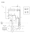
- FIG. 1 is a diagram illustrating a vehicle air conditioner of one embodiment.
- the vehicle air conditioner 11 includes a heat pump system mounted on an automobile, and includes an indoor heat exchange unit 12 (supply flow path) provided on the vehicle interior side and a heat exchanger 13 provided outside the vehicle interior. Prepare. The cabin side and the outside of the cabin are separated by, for example, a dash panel.
- the indoor heat exchange unit 12 is disposed inside the dashboard, and is formed by a duct that introduces outside air or inside air from one end and supplies air into the vehicle interior from the other end.
- a blower fan 14 Inside the indoor heat exchange unit 12, a blower fan 14, an evaporator 15, a condenser 16, and an air mix damper 17 are provided.
- the blower fan 14 is provided at one end of the indoor heat exchange unit 12 and, when driven by a motor, sucks outside air or inside air and discharges it to the other end.
- the evaporator 15 is provided downstream of the blower fan 14 and serves as a heat absorber and a dehumidifier between the air passing around the radiation fins and the low-temperature heat medium (refrigerant) passing through the tube. Perform heat exchange. That is, by evaporating and evaporating the heat medium in the tube, the air around the radiation fins is cooled, and dehumidification is performed by causing dew condensation on the surface of the radiation fins. All the air blown out from the blower fan 14 passes through the evaporator 15.
- the condenser 16 is provided downstream of the evaporator 15 and serves as a radiator for exchanging heat between air passing around the radiation fins and a high-temperature heat medium (heat medium) passing through the tube. Perform That is, the air around the radiation fins is heated by condensing and liquefying the heat medium in the tube.
- the condenser 16 is disposed so as to cover substantially half of the cross section of the indoor heat exchange unit 12, so that a flow path passing through the condenser 16 and a flow path bypassing the condenser 16 are formed. ing. That is, part of the air that has passed through the evaporator 15 passes through the condenser 16, and the rest bypasses the condenser 16.
- the air mix damper 17 opens the flow path passing through the condenser 16 and closes the flow path bypassing the condenser 16, and closes the flow path passing through the condenser 16 to bypass the condenser 16. It is rotatable between a position where the flow path is opened and a position where the flow path is opened. When the air mix damper 17 is at a position where the flow path passing through the condenser 16 is opened and the flow path bypassing the condenser 16 is closed, all the air that has passed through the evaporator 15 passes through the condenser 16.
- the heat exchanger 13 is provided in the engine room or the motor room, and exchanges heat between the outside air passing around the radiation fins and the heat medium passing through the tube.
- the outside air is mainly a traveling wind, but when a sufficient traveling wind cannot be obtained, the outside air is blown to the radiation fins by driving a blower (not shown).
- the heat exchanger 13 functions as an evaporator, that is, a heat absorber, and heat exchange between the outside air passing around the radiation fins and the low-temperature heat medium (refrigerant) passing through the tube. Perform That is, the heat medium in the tube is vaporized and absorbed.
- the heat exchanger 13 When the operation mode is cooling, the heat exchanger 13 functions as a condenser, that is, a radiator, and heat is transferred between the outside air passing around the radiation fins and the high-temperature heat medium (heat medium) passing through the tube. Perform an exchange. That is, the heat medium in the tube is condensed and liquefied to release heat.
- the outlet of the condenser 16 communicates with the inlet of the heat exchanger 13 via the flow path 21.
- the flow path 21 is provided with an expansion valve 31 (first expansion valve).
- the expansion valve 31 reduces the pressure of the high-pressure heat medium, which is a liquid phase, to a low-pressure heat medium that is easily vaporized by blowing out the mist, and the degree of opening can be adjusted from fully closed to fully open.
- the outlet of the heat exchanger 13 communicates with the inlet of the condenser 16 via the flow path 22.
- an on-off valve 32, a check valve 33, an accumulator 34, and a compressor 35 are sequentially provided from the heat exchanger 13 side to the condenser 16 side.
- the on-off valve 32 opens or closes the flow path 22.
- the check valve 33 allows passage from the side of the on-off valve 32 to the side of the accumulator 34 and prevents passage in the reverse direction.
- the accumulator 34 performs gas-liquid separation of the heat medium, and supplies only the heat medium in the gas phase to the compressor 35.
- the compressor 35 compresses a low-pressure heat medium that is a gaseous phase to increase the pressure to a high-pressure heat medium that is easily liquefied, and is an oil supply type in which lubrication is performed by oil circulating together with the heat medium. For example, it is a rotary compressor, a swash plate type compressor, a scroll compressor, or the like.
- the oil concentration in the heat medium is about several percent.
- the drive source of the compressor 35 is an engine or an electric motor.
- the flow path 21 there is a branch point between the heat exchanger 13 and the expansion valve 31, and this branch point communicates with the inlet of the evaporator 15 via the flow path 23.
- An on-off valve 36 and an expansion valve 37 (second expansion valve) are sequentially provided in the flow path 23 from the branch point toward the evaporator 15.
- the on-off valve 36 opens or closes the flow path 23.
- the expansion valve 37 reduces the pressure of the high-pressure heat medium, which is a liquid phase, to a low-pressure heat medium that is easily vaporized by blowing out the mist, and the opening degree can be adjusted from fully closed to fully open.
- the flow path 22 there is a branch point between the heat exchanger 13 and the on-off valve 32, and in the flow path 23, there is a branch point between the on-off valve 36 and the expansion valve 37.
- the points communicate with each other via a flow path 24.
- the flow path 24 is provided with a check valve 38.
- the check valve 38 allows passage from the side of the flow path 22 to the side of the flow path 23 and prevents passage in the reverse direction.
- there is a branch point between the on-off valve 32 and the check valve 33 and this branch point communicates with the outlet of the evaporator 15 via the flow path 25.
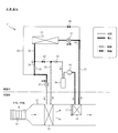
- FIG. 2 is a diagram illustrating a heating operation.
- the flow path through which the low-pressure heat medium passes is indicated by a thick dotted line
- the flow path through which the high-pressure heat medium passes is indicated by a thick solid line
- the open on-off valve is shown in white
- the closed on-off valve is shown. Shown in black.
- the heat medium circulates through the compressor 35, the condenser 16, the expansion valve 31, the heat exchanger 13, the on-off valve 32, the check valve 33, and the accumulator 34 in this order.
- the heat medium in the gas phase is compressed by the compressor 35 to have a high pressure, is condensed and liquefied in the condenser 16, and is cooled to a low temperature by heat radiation.
- the heat medium in the liquid phase is expanded by the expansion valve 31 to have a low pressure, evaporates and evaporates in the heat exchanger 13, and has a high temperature due to heat absorption.
- the blower fan 14 is driven and the flow path passing through the condenser 16 is opened by the air mix damper 17. Thereby, the introduced air is heated by the condenser 16, and warm air is supplied into the vehicle interior.
- FIG. 3 is a diagram illustrating the cooling operation.
- the flow path through which the low-pressure heat medium passes is indicated by a thick dotted line
- the flow path through which the high-pressure heat medium passes is indicated by a thick solid line
- the open on-off valve is shown in white
- the closed on-off valve is shown. Shown in black.
- the heat medium passes through the compressor 35, the condenser 16, the expansion valve 31, the heat exchanger 13, the check valve 38, the expansion valve 37, the evaporator 15, the check valve 33, and the accumulator 34 in this order. Circulate.
- the heat medium in the gas phase is compressed by the compressor 35 to have a high pressure, is condensed and liquefied in the condenser 16, and is cooled to a low temperature by heat radiation.
- the heat medium that is being liquefied is further condensed and liquefied in the heat exchanger 13, and is further cooled by heat radiation.
- the heat medium in the liquid phase is expanded by the expansion valve 37 to have a low pressure, evaporates and evaporates in the evaporator 15, and becomes high in temperature by heat absorption.
- the blower fan 14 is driven and the flow path passing through the condenser 16 is closed by the air mix damper 17.
- the air bypasses the condenser 16 and cool dehumidified air is supplied into the vehicle interior.
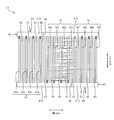
- FIG. 4 is a diagram illustrating a heat exchanger.
- the heat exchanger 13 includes a pair of upper and lower headers 41, a plurality of tubes 42, and a plurality of fins 43.
- the pair of headers 41 extend in the horizontal direction and are provided at intervals in the vertical direction.
- the header 41 is formed by a cylindrical pipe whose both ends are closed, and the inside is partitioned by a partition 46 into sections arranged in a lateral direction.
- the inside of the upper header 41 is divided into a section 41A on one side in the horizontal direction and a section 41B on the other side in the horizontal direction, and an inlet 44 is provided in the section 41A on one side in the horizontal direction.
- the inside of the lower header 41 is divided into a section 41C on one side in the horizontal direction and a section 41D on the other side in the horizontal direction, and a discharge port 45 is provided in the section 41D on the other side in the horizontal direction.
- Each tube 42 extends in the up-down direction, the upper end and the lower end are respectively connected to the header 41, and are provided at equal intervals along the horizontal direction.
- the tube 42 is thin and flat in the lateral direction, and both ends are connected to the inside of the header 41 and brazed to the header 41.
- 42a to 42l are sequentially set from one end in the horizontal direction to the other end.
- the tube 42d and the tube 42e are partitioned by a partition wall 46.
- the tube 42h and the tube 42e are separated. i is partitioned by a partition wall 46.
- Each fin 43 is fixed between adjacent tubes 42 by brazing.
- a flow path is formed by the header 41 and the tube 42, through which the heat medium flows. That is, first, it flows into the section 41A at one lateral side of the upper header 41 via the inflow port 44, is distributed to the tubes 42a to 42d, and then flows into the section 41C at one lateral side of the lower header 41. Next, after being distributed to the tubes 42e to 42h, it flows into the section 41B on the other side in the horizontal direction of the upper header 41, and is then distributed to the tubes 42i to 42l and then flows to the other side in the lower header 41. It flows into the section 41D and is discharged through the discharge port 45. Thus, when the heat medium flows through each tube 42, heat exchange is performed between the heat medium and air flowing around the tubes 42 and the fins 43.
- the flow of the heat medium flowing from one header 41 to the other header 41 through the plurality of tubes 42 is defined as one path, and a path that flows downward and a path that flows upward Are provided alternately.
- the path flowing downward through the tubes 42a to 42d is referred to as a first path P1
- the path flowing upward through the tubes 42e to 42h is referred to as a second path P2
- the path flowing through is referred to as a third path P3.
- the first path P1, the second path P2, and the third path P3 are equal paths in which the number of tubes 42 is the same.
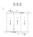
- FIG. 5 is a diagram schematically illustrating an equal path.
- each pass schematically represents the number of tubes 42.
- the reference number of the tubes 42 is represented by “2”
- the number larger than the reference number is represented by “3”
- the number smaller than the reference number is represented by “1”.
- all of the first path P1, the second path P2, and the third path P3 are the reference “2”.
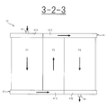
- FIG. 6 is a diagram schematically illustrating a configuration in which the ascending path is narrowed (3-2-3).
- the first path P1 is set to “3”
- the second path P2 is set to “2”
- the third path P3 is set to “3”. That is, the second path P2 is narrower than the first path P1 and the third path P3.
- FIG. 7 is a diagram schematically illustrating a configuration in which the ascending path is narrowed (2-1-3).
- the first path P1 is set to “2”
- the second path P2 is set to “1”
- the third path P3 is set to “3”. That is, the second path P2 is narrower than the first path P1 and the third path P3.
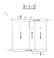
- FIG. 8 is a diagram schematically illustrating a configuration in which the ascending path is narrowed (3-1-2).
- the first path P1 is set to “3”
- the second path P2 is set to “1”
- the third path P3 is set to “2”. That is, the second path P2 is narrower than the first path P1 and the third path p3.
- the first path P1 on the entrance side is wider than the third path P3 on the exit side.
- the first first pass P1 is a descending pass that flows from top to bottom, that is, follows gravity. Thereby, the heat medium easily flows.
- the number of passes is three, that is, an odd number.
- the last third pass P3 is also a descending pass that flows downward, and the heat medium easily flows. If the last third pass P3 flows upward from the bottom, that is, if it is a rising pass against gravity, the oil circulating together with the heat medium will not be easily discharged. Therefore, by using the last third pass P3 as a descending pass, the accumulation of oil can be suppressed. Further, as the number of passes increases, the pressure loss increases, and therefore, the number of passes is preferably three.
- the second pass P2 which is the ascending pass the liquid phase heat medium is less likely to rise than the gas phase heat medium. Therefore, the heat medium in the liquid phase hardly flows into the tube 42 closer to the first path P1 of the second path P2, and easily flows to the tube 42 closer to the third path P3. That is, a bias occurs in the branch flow in the second path P2, which affects the heat exchange performance. Therefore, in the second path P2 which is the ascending path, the flow path is narrower than the other paths. That is, the number of tubes 42 is reduced in the second pass P2 which is the ascending pass, as compared with the other passes. Thereby, it is possible to suppress the occurrence of bias in the branch flow in the second path P2, and to improve the heat exchange performance. Furthermore, since the first path P1 and the third path P3 can be widened by an amount corresponding to the narrowing of the second path P2, the space can be effectively used and the heat exchange performance can be improved.
- the first path P1 is set to “3” wider than the reference
- the second path P2 is set to “2” of the reference
- the third path P3 is “3” wider than the reference.
- Is set to The second path P2, which is an ascending path, tends to have a bias in the branch flow. Therefore, by making the second path P2 relatively narrowest, it is possible to suppress the bias in the branch flow.
- the first path P1 is set to the reference “2”
- the second path P2 is set to “1” narrower than the reference
- the third path P3 is set to “3” wider than the reference.
- the outdoor heat exchanger 13 functions as an evaporator during heating, the heat medium evaporates closer to the outlet of the heat exchanger 13. Since the gas phase has a lower density of the heat medium and a higher flow velocity than the liquid phase, the pressure loss is large. That is, at the time of heating, the pressure loss increases in the outlet side path where the heat medium evaporates. Therefore, the third path P3 on the exit side is wider than the first path P1 on the entrance side. That is, the number of tubes 42 in the third path P3 on the outlet side is larger than that in the first path P1 on the inlet side. Thereby, pressure loss at the time of heating can be reduced, and heat exchange performance can be improved. Therefore, it is suitable for a vehicle in which heating is prioritized. Further, since frost starts to be formed from the outlet side during heating, the flow path on the outlet side is widened, so that the blockage of the ventilation path due to the frost can be suppressed.
- the first path P1 is set to “3” wider than the reference
- the second path P2 is set to “1” narrower than the reference
- the third path P3 is set to “2” of the reference.
- the first path P1 on the entrance side is wider than the third path P3 on the exit side. That is, the number of tubes 42 in the first path P1 on the inlet side is larger than that in the third path P3 on the outlet side. Thereby, pressure loss during cooling can be reduced, and heat exchange performance can be improved. Therefore, it is suitable for a vehicle in which cooling is prioritized.
- the number of paths is three, but is not limited to this. Since the number of passes may be an odd number of three or more, the number of passes may be set to, for example, five.
- the width of the flow path in each path is adjusted by the number of tubes 42, but is not limited to this. For example, the adjustment may be made according to the flow path cross-sectional area of the tube 42.
- the condenser 16 is provided as a heat source for heating, but the present invention is not limited to this, and another heat source may be separately added.
- a PTC heater PTC: Positive Temperature Coefficient
Abstract
【課題】上に向かって流れるパスで分流に偏りが生じることを抑制し、熱交換性能を向上させる。 【解決手段】上に向かって流れるパスは、他のパスに比べて流路が狭くされている。
Description
本発明は、熱交換器、車両用空気調和装置に関するものである。
熱交換器では、一方のヘッダから他方のヘッダへの流れを一パスとしている。特許文献1に示されるように、熱交換器には一般に複数のパスが設けられ、且つ各パスの流れが略均等になるように構成されている。
熱交換器では、下に向かって流れる下降パスと上に向かって流れる上昇パスとが交互に設けられており、上昇パスでは、液相の熱媒体は気相の熱媒体に比べて上昇しにくい。そのため、液相の熱媒体は、上昇パスのうち、上流に近い側には流れにくくなり、下流に近い側に流れやすくなる。したがって、上昇パス内の分流に偏りが生じ、熱交換性能に影響してしまう。
本発明の課題は、上に向かって流れるパスで分流に偏りが生じることを抑制し、熱交換性能を向上させることにある。
本発明の課題は、上に向かって流れるパスで分流に偏りが生じることを抑制し、熱交換性能を向上させることにある。
本発明の一態様に係る熱交換器は、
横方向に延び、上下方向に間隔を空けて設けられた一対のヘッダと、
上下方向に延び、上端及び下端の夫々がヘッダに接続され、横方向に間隔を空けて設けられた複数のチューブと、を備え、
複数のチューブを通って一方のヘッダから他方のヘッダに向かって流れる熱媒体の流れを一つのパスとし、下に向かって流れるパスと上に向かって流れるパスとが交互に設けられており、
各パスにおける熱媒体の流れは、暖房時及び冷房時で共通であり、
最初のパスは、下に向かって流れるパスであり、
パス数は、三以上の奇数であり、
上に向かって流れるパスは、他のパスに比べて流路が狭くされている。
横方向に延び、上下方向に間隔を空けて設けられた一対のヘッダと、
上下方向に延び、上端及び下端の夫々がヘッダに接続され、横方向に間隔を空けて設けられた複数のチューブと、を備え、
複数のチューブを通って一方のヘッダから他方のヘッダに向かって流れる熱媒体の流れを一つのパスとし、下に向かって流れるパスと上に向かって流れるパスとが交互に設けられており、
各パスにおける熱媒体の流れは、暖房時及び冷房時で共通であり、
最初のパスは、下に向かって流れるパスであり、
パス数は、三以上の奇数であり、
上に向かって流れるパスは、他のパスに比べて流路が狭くされている。
本発明によれば、上に向かって流れるパスは、他のパスに比べて流路が狭くされているので、分流に偏りが生じることを抑制し、熱交換性能を向上させることができる。
以下、本発明の実施形態を図面に基づいて説明する。なお、各図面は模式的なものであって、現実のものとは異なる場合がある。また、以下の実施形態は、本発明の技術的思想を具体化するための装置や方法を例示するものであり、構成を下記のものに特定するものでない。すなわち、本発明の技術的思想は、特許請求の範囲に記載された技術的範囲内において、種々の変更を加えることができる。
《一実施形態》
《構成》
図1は、一実施形態の車両用空気調和装置を示す図である。
車両用空気調和装置11は、自動車に搭載されるヒートポンプシステムからなり、車室側に設けられた室内熱交換ユニット12(供給流路)と、車室外に設けられた熱交換器13と、を備える。車室側と車室外とは、例えばダッシュパネルによって隔てられている。
室内熱交換ユニット12は、ダッシュボードの内部に配置されており、一端側から外気や内気を導入し、他端側から車室内へ空気を供給するダクトによって形成されている。室内熱交換ユニット12の内部には、送風ファン14と、蒸発器15と、凝縮器16と、エアミックスダンパ17と、が設けられている。
《構成》
図1は、一実施形態の車両用空気調和装置を示す図である。
車両用空気調和装置11は、自動車に搭載されるヒートポンプシステムからなり、車室側に設けられた室内熱交換ユニット12(供給流路)と、車室外に設けられた熱交換器13と、を備える。車室側と車室外とは、例えばダッシュパネルによって隔てられている。
室内熱交換ユニット12は、ダッシュボードの内部に配置されており、一端側から外気や内気を導入し、他端側から車室内へ空気を供給するダクトによって形成されている。室内熱交換ユニット12の内部には、送風ファン14と、蒸発器15と、凝縮器16と、エアミックスダンパ17と、が設けられている。
送風ファン14は、室内熱交換ユニット12の一端側に設けられており、モータによって駆動されるときに、外気や内気を吸引し、他端側へと吐出する。
蒸発器15は、送風ファン14よりも下流側に設けられており、吸熱器及び除湿器として、放熱フィンの周囲を通過する空気とチューブ内を通過する低温の熱媒体(冷媒)との間で熱交換を行なう。すなわち、チューブ内の熱媒体を蒸発気化させることで、放熱フィンの周囲の空気を冷却すると共に、放熱フィンの表面に結露を生じさせて除湿を行なう。送風ファン14から吹き出された空気は、全て蒸発器15を通過する。
蒸発器15は、送風ファン14よりも下流側に設けられており、吸熱器及び除湿器として、放熱フィンの周囲を通過する空気とチューブ内を通過する低温の熱媒体(冷媒)との間で熱交換を行なう。すなわち、チューブ内の熱媒体を蒸発気化させることで、放熱フィンの周囲の空気を冷却すると共に、放熱フィンの表面に結露を生じさせて除湿を行なう。送風ファン14から吹き出された空気は、全て蒸発器15を通過する。
凝縮器16は、蒸発器15よりも下流側に設けられており、放熱器として、放熱フィンの周囲を通過する空気とチューブ内を通過する高温の熱媒体(熱媒)との間で熱交換を行なう。すなわち、チューブ内の熱媒体を凝縮液化させることで、放熱フィンの周囲の空気を加熱する。凝縮器16は、室内熱交換ユニット12の断面のうち、略半分を塞ぐように配置されることで、凝縮器16を通過する流路と、凝縮器16を迂回する流路と、が形成されている。すなわち、蒸発器15を通過した空気の一部が凝縮器16を通過し、残りが凝縮器16を迂回する。
エアミックスダンパ17は、凝縮器16を通過する流路を開放して凝縮器16を迂回する流路を閉鎖する位置と、凝縮器16を通過する流路を閉鎖して凝縮器16を迂回する流路を開放する位置と、の間で回動可能である。エアミックスダンパ17が凝縮器16を通過する流路を開放して凝縮器16を迂回する流路を閉鎖する位置にあるときには、蒸発器15を通過した空気は全て凝縮器16を通過する。エアミックスダンパ17が凝縮器16を通過する流路を閉鎖して凝縮器16を迂回する流路を開放する位置にあるときには、蒸発器15を通過した空気は全て凝縮器16を迂回する。エアミックスダンパ17が凝縮器16を通過する流路と凝縮器16を迂回する流路の双方を開放する位置にあるときには、蒸発器15を通過した空気のうち、一部が凝縮器16を通過し、残りが凝縮器16を迂回する。そして、凝縮器16の下流側で、凝縮器16を通過した空気と、凝縮器16を迂回した空気とが混合される。
熱交換器13は、エンジンルーム内又はモータルーム内に設けられており、放熱フィンの周囲を通過する外気とチューブ内を通過する熱媒体との間で熱交換を行なう。外気とは
主に走行風であるが、十分な走行風が得られないときは、図示しない送風機が駆動されることで、放熱フィンに対して外気が送風される。
運転モードを暖房とするときには、熱交換器13を蒸発器、つまり吸熱器として機能させ、放熱フィンの周囲を通過する外気とチューブ内を通過する低温の熱媒体(冷媒)との間で熱交換を行なう。すなわち、チューブ内の熱媒体を蒸発気化させ、吸熱させる。
運転モードを冷房とするときには、熱交換器13を凝縮器、つまり放熱器として機能させ、放熱フィンの周囲を通過する外気とチューブ内を通過する高温の熱媒体(熱媒)との間で熱交換を行なう。すなわち、チューブ内の熱媒体を凝縮液化させ、放熱させる。
主に走行風であるが、十分な走行風が得られないときは、図示しない送風機が駆動されることで、放熱フィンに対して外気が送風される。
運転モードを暖房とするときには、熱交換器13を蒸発器、つまり吸熱器として機能させ、放熱フィンの周囲を通過する外気とチューブ内を通過する低温の熱媒体(冷媒)との間で熱交換を行なう。すなわち、チューブ内の熱媒体を蒸発気化させ、吸熱させる。
運転モードを冷房とするときには、熱交換器13を凝縮器、つまり放熱器として機能させ、放熱フィンの周囲を通過する外気とチューブ内を通過する高温の熱媒体(熱媒)との間で熱交換を行なう。すなわち、チューブ内の熱媒体を凝縮液化させ、放熱させる。
次に、熱媒体の回路構成について説明する。
凝縮器16の出口は、流路21を介して熱交換器13の入口に連通している。流路21には、膨張弁31(第一の膨張弁)が設けられている。
膨張弁31は、液相である高圧の熱媒体を霧状にして吹き出すことにより、気化しやすい低圧の熱媒体に減圧するものであり、開度が全閉から全開まで調整可能である。
熱交換器13の出口は、流路22を介して凝縮器16の入口に連通している。流路22には、熱交換器13の側から凝縮器16の側に向かって、開閉弁32、逆止弁33、アキュムレータ34、及び圧縮機35が、順に設けられている。
凝縮器16の出口は、流路21を介して熱交換器13の入口に連通している。流路21には、膨張弁31(第一の膨張弁)が設けられている。
膨張弁31は、液相である高圧の熱媒体を霧状にして吹き出すことにより、気化しやすい低圧の熱媒体に減圧するものであり、開度が全閉から全開まで調整可能である。
熱交換器13の出口は、流路22を介して凝縮器16の入口に連通している。流路22には、熱交換器13の側から凝縮器16の側に向かって、開閉弁32、逆止弁33、アキュムレータ34、及び圧縮機35が、順に設けられている。
開閉弁32は、流路22を開放又は閉鎖する。
逆止弁33は、開閉弁32の側からアキュムレータ34の側への通過を許容し、逆方向の通過を阻止する。
アキュムレータ34は、熱媒体の気液分離を行ない、気相の熱媒体だけを圧縮機35へと供給する。
圧縮機35は、気相である低圧の熱媒体を圧縮することにより、液化しやすい高圧の熱媒体に昇圧させるものであり、熱媒体と共に循環するオイルによって潤滑が行なわれる給油式である。例えば、ロータリー圧縮機、斜板式圧縮機、スクロール圧縮機等である。熱媒体に対するオイル濃度は数%程度である。圧縮機35の駆動源は、エンジンや電動モータである。
逆止弁33は、開閉弁32の側からアキュムレータ34の側への通過を許容し、逆方向の通過を阻止する。
アキュムレータ34は、熱媒体の気液分離を行ない、気相の熱媒体だけを圧縮機35へと供給する。
圧縮機35は、気相である低圧の熱媒体を圧縮することにより、液化しやすい高圧の熱媒体に昇圧させるものであり、熱媒体と共に循環するオイルによって潤滑が行なわれる給油式である。例えば、ロータリー圧縮機、斜板式圧縮機、スクロール圧縮機等である。熱媒体に対するオイル濃度は数%程度である。圧縮機35の駆動源は、エンジンや電動モータである。
流路21のうち、熱交換器13と膨張弁31との間には分岐点があり、この分岐点は、流路23を介して蒸発器15の入口に連通している。流路23には、分岐点の側から蒸発器15の側に向かって、開閉弁36、及び膨張弁37(第二の膨張弁)が、順に設けられている。
開閉弁36は、流路23を開放又は閉鎖する。
膨張弁37は、液相である高圧の熱媒体を霧状にして吹き出すことにより、気化しやすい低圧の熱媒体に減圧するものであり、開度が全閉から全開まで調整可能である。
開閉弁36は、流路23を開放又は閉鎖する。
膨張弁37は、液相である高圧の熱媒体を霧状にして吹き出すことにより、気化しやすい低圧の熱媒体に減圧するものであり、開度が全閉から全開まで調整可能である。
流路22のうち、熱交換器13と開閉弁32との間には分岐点があり、また流路23のうち、開閉弁36と膨張弁37との間には分岐点があり、これら分岐点同士は、流路24を介して連通している。流路24には、逆止弁38が設けられている。
逆止弁38は、流路22の側から流路23の側への通過を許容し、逆方向の通過を阻止する。
流路22のうち、開閉弁32と逆止弁33との間には分岐点があり、この分岐点は、流路25を介して蒸発器15の出口に連通している。
逆止弁38は、流路22の側から流路23の側への通過を許容し、逆方向の通過を阻止する。
流路22のうち、開閉弁32と逆止弁33との間には分岐点があり、この分岐点は、流路25を介して蒸発器15の出口に連通している。
次に、各運転モードについて説明する。
[暖房運転]
図2は、暖房運転を示す図である。
図中、低圧の熱媒体が通過する流路を太い点線で示し、高圧の熱媒体が通過する流路を太い実線で示し、開放された開閉弁を白抜きで示し、閉鎖された開閉弁を黒塗りで示して
いる。
運転モードが暖房であるときには、膨張弁31を僅かに解放し、開閉弁32を開放し、開閉弁36を閉鎖し、膨張弁37を閉鎖した状態で、圧縮機35を駆動する。
[暖房運転]
図2は、暖房運転を示す図である。
図中、低圧の熱媒体が通過する流路を太い点線で示し、高圧の熱媒体が通過する流路を太い実線で示し、開放された開閉弁を白抜きで示し、閉鎖された開閉弁を黒塗りで示して
いる。
運転モードが暖房であるときには、膨張弁31を僅かに解放し、開閉弁32を開放し、開閉弁36を閉鎖し、膨張弁37を閉鎖した状態で、圧縮機35を駆動する。
これにより、熱媒体は、圧縮機35、凝縮器16、膨張弁31、熱交換器13、開閉弁32、逆止弁33、及びアキュムレータ34を順に経由して循環する。この循環経路において、気相の熱媒体は、圧縮機35で圧縮され高圧となり、凝縮器16で凝縮液化し、放熱によって低温になる。液相の熱媒体は、膨張弁31で膨張され低圧となり、熱交換器13で蒸発気化し、吸熱によって高温となる。
一方、室内熱交換ユニット12では、送風ファン14を駆動すると共に、エアミックスダンパ17で凝縮器16を通過する流路を開放する。これにより、導入された空気が凝縮器16で加熱され、温かい空気が車室内に供給される。
一方、室内熱交換ユニット12では、送風ファン14を駆動すると共に、エアミックスダンパ17で凝縮器16を通過する流路を開放する。これにより、導入された空気が凝縮器16で加熱され、温かい空気が車室内に供給される。
[冷房運転]
図3は、冷房運転を示す図である。
図中、低圧の熱媒体が通過する流路を太い点線で示し、高圧の熱媒体が通過する流路を太い実線で示し、開放された開閉弁を白抜きで示し、閉鎖された開閉弁を黒塗りで示している。
運転モードが冷房であるときには、膨張弁31を全開放し、開閉弁32を閉鎖し、開閉弁36を閉鎖し、膨張弁37を僅かに解放した状態で、圧縮機35を駆動する。
図3は、冷房運転を示す図である。
図中、低圧の熱媒体が通過する流路を太い点線で示し、高圧の熱媒体が通過する流路を太い実線で示し、開放された開閉弁を白抜きで示し、閉鎖された開閉弁を黒塗りで示している。
運転モードが冷房であるときには、膨張弁31を全開放し、開閉弁32を閉鎖し、開閉弁36を閉鎖し、膨張弁37を僅かに解放した状態で、圧縮機35を駆動する。
これにより、熱媒体は、圧縮機35、凝縮器16、膨張弁31、熱交換器13、逆止弁38、膨張弁37、蒸発器15、逆止弁33、及びアキュムレータ34を順に経由して循環する。この循環経路において、気相の熱媒体は、圧縮機35で圧縮され高圧となり、凝縮器16で凝縮液化し、放熱によって低温になる。液化しつつある熱媒体は、熱交換器13でさらに凝縮液化し、放熱によってさらに低温になる。液相の熱媒体は、膨張弁37で膨張され低圧となり、蒸発器15で蒸発気化し、吸熱によって高温となる。
一方、室内熱交換ユニット12では、送風ファン14を駆動すると共に、エアミックスダンパ17で凝縮器16を通過する流路を閉鎖する。これにより、導入された空気が蒸発器15で冷却及び除湿された後に、凝縮器16を迂回し、除湿された涼しい空気が車室内に供給される。
一方、室内熱交換ユニット12では、送風ファン14を駆動すると共に、エアミックスダンパ17で凝縮器16を通過する流路を閉鎖する。これにより、導入された空気が蒸発器15で冷却及び除湿された後に、凝縮器16を迂回し、除湿された涼しい空気が車室内に供給される。
次に、熱交換器13について説明する。
図4は、熱交換器を示す図である。
熱交換器13は、上下一対のヘッダ41と、複数のチューブ42と、複数のフィン43と、を備える。
一対のヘッダ41は、横方向に延び、上下方向に間隔を空けて設けられている。ヘッダ41は、両端が閉塞された円筒状の配管によって形成されており、内部は隔壁46によって横方向に並んだ区画に仕切られている。上方のヘッダ41は、内部が横方向一端側の区画41Aと横方向他端側の区画41Bとに分けられており、横方向一端側の区画41Aには流入口44が設けられている。下方のヘッダ41は、内部が横方向一端側の区画41Cと横方向他端側の区画41Dとに分けられており、横方向他端側の区画41Dには排出口45が設けられている。
各チューブ42は、上下方向に延び、上端及び下端の夫々がヘッダ41に接続され、横方向に沿って等間隔に設けられている。チューブ42は横方向に薄い扁平形状であり、両端をヘッダ41の内部に連通させてヘッダ41にろう付けされている。ここでは12本ある場合を示してあり、夫々を識別する場合は、横方向の一端から他端に向かって順に42a~42lとする。上方のヘッダ41では、チューブ42dとチューブ42eとの間が隔壁46によって仕切られており、下方のヘッダ41では、チューブ42hとチューブ42
iとの間が隔壁46によって仕切られている。
各フィン43は、隣り合うチューブ42同士の間にろう付けによって固定されている。
iとの間が隔壁46によって仕切られている。
各フィン43は、隣り合うチューブ42同士の間にろう付けによって固定されている。
ヘッダ41及びチューブ42によって流路が形成されており、そこを熱媒体が流れる。すなわち、先ず流入口44を介して上方のヘッダ41における横方向一端側の区画41Aへ流入し、チューブ42a~42dに分配されてから下方のヘッダ41における横方向一端側の区画41Cへ流入する。次にチューブ42e~42hに分配されてから上方のヘッダ41における横方向他端側の区画41Bへ流入し、次にチューブ42i~42lに分配されてから下方のヘッダ41における横方向他端側の区画41Dへ流入し、排出口45を介して排出される。こうして、熱媒体は各チューブ42を流れるときに、チューブ42及びフィン43の周囲を流れる空気との間で熱交換を行なう。
熱交換器13では、複数のチューブ42を通って一方のヘッダ41から他方のヘッダ41に向かって流れる熱媒体の流れを一つのパスとし、下に向かって流れるパスと上に向かって流れるパスとが交互に設けられている。チューブ42a~42dを通って下に向かって流れるパスを第一パスP1とし、チューブ42e~42hを通って上に向かって流れるパスを第二パスP2とし、チューブ42i~42lを通って下に向かって流れるパスを第三パスP3とする。ここでは、説明を簡単にするために、第一パスP1、第二パスP2、及び第三パスP3で、チューブ42の本数を同一とする均等パスとしている。
図5は、均等パスを模式的に示す図である。
各パスの幅は、チューブ42の本数を模式的に表している。以下の説明では、チューブ42の基準となる本数を『2』で表し、基準となる本数よりも多い本数を『3』で表し、基準となる本数よりも少ない本数を『1』で表す。ここでは、第一パスP1、第二パスP2、及び第三パスP3の全てが、基準の『2』となる。
図5は、均等パスを模式的に示す図である。
各パスの幅は、チューブ42の本数を模式的に表している。以下の説明では、チューブ42の基準となる本数を『2』で表し、基準となる本数よりも多い本数を『3』で表し、基準となる本数よりも少ない本数を『1』で表す。ここでは、第一パスP1、第二パスP2、及び第三パスP3の全てが、基準の『2』となる。
次に、本実施形態におけるパスの設定例を示す。
図6は、上昇パスを狭くした構成を模式的に示す図である(3‐2‐3)。
ここでは、第一パスP1を『3』に設定し、第二パスP2を『2』に設定し、第三パスP3を『3』に設定している。すなわち、第二パスP2は、第一パスP1及び第三パスP3よりも狭い。
図7は、上昇パスを狭くした構成を模式的に示す図である(2‐1‐3)。
ここでは、第一パスP1を『2』に設定し、第二パスP2を『1』に設定し、第三パスP3を『3』に設定している。すなわち、第二パスP2は、第一パスP1及び第三パスP3よりも狭い。また、出口側の第三パスP3は、入口側の第一パスP1よりも広い。
図8は、上昇パスを狭くした構成を模式的に示す図である(3‐1‐2)。
ここでは、第一パスP1を『3』に設定し、第二パスP2を『1』に設定し、第三パスP3を『2』に設定している。すなわち、第二パスP2は、第一パスP1及び第三パスp3よりも狭い。また、入口側の第一パスP1は、出口側の第三パスP3よりも広い。
《作用》
次に、一実施形態の主要な作用効果について説明する。
熱交換器13は、各パスにおける熱媒体の流れが暖房時と冷房時とで共通である。これにより、運転モードが切り替わるとしても、熱媒体の入口と出口を常に一定にすることができる。そして、最初の第一パスP1は、上から下に向かって流れる、つまり重力に従う下降パスである。これにより、熱媒体が流れやすくなる。また、パス数は三、つまり奇数である。これにより、最後の第三パスP3も下に向かって流れる下降パスとし、熱媒体が流れやすくなる。最後の第三パスP3が、下から上に向かって流れる、つまり重力に逆らう上昇パスになると、熱媒体と共に循環するオイルが排出されにくくなる。したがって、最後の第三パスP3を下降パスとすることで、オイルの滞留を抑制できる。また、パス数が増えると、圧力損失が大きくなるため、パス数は三が好ましい。
一方、上昇パスとなる第二パスP2では、液相の熱媒体は気相の熱媒体に比べて上昇しにくい。そのため、液相の熱媒体は、第二パスP2のうち、第一パスP1に近い側のチューブ42には流れにくくなり、第三パスP3に近い側のチューブ42に流れやすくなる。すなわち、第二パスP2内の分流に偏りが生じ、熱交換性能に影響してしまう。
そこで、上昇パスとなる第二パスP2では、他のパスに比べて流路が狭くされている。すなわち、上昇パスとなる第二パスP2では、他のパスに比べてチューブ42の本数が少なくされている。これにより、第二パスP2内で分流に偏りが生じることを抑制し、熱交換性能を向上させることができる。さらに、第二パスP2を狭くした分だけ、第一パスP1や第三パスP3を広くすることができるので、スペースを有効利用し、熱交換性能を向上させることができる。
そこで、上昇パスとなる第二パスP2では、他のパスに比べて流路が狭くされている。すなわち、上昇パスとなる第二パスP2では、他のパスに比べてチューブ42の本数が少なくされている。これにより、第二パスP2内で分流に偏りが生じることを抑制し、熱交換性能を向上させることができる。さらに、第二パスP2を狭くした分だけ、第一パスP1や第三パスP3を広くすることができるので、スペースを有効利用し、熱交換性能を向上させることができる。
図6の構成によれば、第一パスP1は基準よりも広い『3』に設定され、第二パスP2は基準の『2』に設定され、第三パスP3は基準よりも広い『3』に設定されている。上昇パスとなる第二パスP2は、分流に偏りが生じやすいため、この第二パスP2を相対的に最も狭くすることで、分流に偏りが生じることを抑制できる。
図7の構成によれば、第一パスP1は基準の『2』に設定され、第二パスP2は基準よりも狭い『1』に設定され、第三パスP3は基準よりも広い『3』に設定されている。暖房時に室外の熱交換器13は、蒸発器として機能するため、熱交換器13の出口に近づくほど熱媒体が気化する。気相は液相に比べて熱媒体の密度が低く、流速が速いため、圧力損失は大きい。すなわち、暖房時には、熱媒体が気化する出口側のパスで圧力損失が大きくなってしまう。そこで、出口側の第三パスP3は、入口側の第一パスP1に比べて広くされている。すなわち、出口側の第三パスP3は、入口側の第一パスP1に比べてチューブ42の本数が多くされている。これにより、暖房時の圧力損失を低減し、熱交換性能を向上させることができる。したがって、暖房が優先される車両に好適である。また、暖房時は出口側から着霜し始めるため、出口側の流路を広くすることで、着霜に起因した通風路の閉塞を抑制することができる。
図7の構成によれば、第一パスP1は基準の『2』に設定され、第二パスP2は基準よりも狭い『1』に設定され、第三パスP3は基準よりも広い『3』に設定されている。暖房時に室外の熱交換器13は、蒸発器として機能するため、熱交換器13の出口に近づくほど熱媒体が気化する。気相は液相に比べて熱媒体の密度が低く、流速が速いため、圧力損失は大きい。すなわち、暖房時には、熱媒体が気化する出口側のパスで圧力損失が大きくなってしまう。そこで、出口側の第三パスP3は、入口側の第一パスP1に比べて広くされている。すなわち、出口側の第三パスP3は、入口側の第一パスP1に比べてチューブ42の本数が多くされている。これにより、暖房時の圧力損失を低減し、熱交換性能を向上させることができる。したがって、暖房が優先される車両に好適である。また、暖房時は出口側から着霜し始めるため、出口側の流路を広くすることで、着霜に起因した通風路の閉塞を抑制することができる。
図8の構成によれば、第一パスP1は基準よりも広い『3』に設定され、第二パスP2は基準よりも狭い『1』に設定され、第三パスP3は基準の『2』に設定されている。冷房時に室外の熱交換器13は、凝縮器として機能するため、熱交換器13の出口に近いほど熱媒体が液化する。つまり、入口側では熱媒体が気相である。気相は液相に比べて熱媒体の密度が低く、流速が速いため、圧力損失は大きい。すなわち、冷房時には、熱媒体が気相となる入口側のパスで圧力損失が大きくなってしまう。そこで、入口側の第一パスP1は、出口側の第三パスP3に比べて広くされている。すなわち、入口側の第一パスP1は、出口側の第三パスP3に比べてチューブ42の本数が多くされている。これにより、冷房時の圧力損失を低減し、熱交換性能を向上させることができる。したがって、冷房が優先される車両に好適である。
《変形例》
本実施形態では、パス数を三にしているが、これに限定されるものではない。パス数は三以上の奇数であればよいので、パス数を例えば五にしてもよい。
本実施形態では、各パスにおける流路の広さを、チューブ42の本数によって調整しているが、これに限定されるものではない。例えば、チューブ42の流路断面積によって調整してもよい。
本実施形態では、室内熱交換ユニット12において、暖房用の熱源として凝縮器16のみを設けているが、これに限定されるものではなく、別途、他の熱源を追加してもよい。例えば、温度によって抵抗値が変化するPTCヒータ(PTC:Positive Temperature Coefficient)を設けてもよい。これによれば、暖房効果が向上する。
以上、限られた数の実施形態を参照しながら説明したが、権利範囲はそれらに限定されるものではなく、上記の開示に基づく実施形態の改変は、当業者にとって自明のことである。
11…車両用空気調和装置、12…室内熱交換ユニット、13…熱交換器、14…送風ファン、15…蒸発器、16…凝縮器、17…エアミックスダンパ、21…流路、22…流路、23…流路、24…流路、25…流路、31…膨張弁、32…開閉弁、33…逆止弁、34…アキュムレータ、35…圧縮機、36…開閉弁、37…膨張弁、38…逆止弁、41…ヘッダ、41A…区画、41B…区画、41C…区画、41D…区画、42…チューブ、43…フィン、44…流入口、45…排出口、46…隔壁、P1…第一パス、P2…第二パス、P3…第三パス
Claims (6)
- 横方向に延び、上下方向に間隔を空けて設けられた一対のヘッダと、
上下方向に延び、上端及び下端の夫々が前記ヘッダに接続され、横方向に間隔を空けて設けられた複数のチューブと、を備え、
複数の前記チューブを通って一方の前記ヘッダから他方の前記ヘッダに向かって流れる熱媒体の流れを一つのパスとし、下に向かって流れるパスと上に向かって流れるパスとが交互に設けられており、
各パスにおける前記熱媒体の流れは、暖房時及び冷房時で共通であり、
最初のパスは、下に向かって流れるパスであり、
パス数は、三以上の奇数であり、
上に向かって流れるパスは、他のパスに比べて流路が狭くされていることを特徴とする熱交換器。 - 出口側のパスは、他のパスに比べて流路が広くされていることを特徴とする請求項1に記載の熱交換器。
- 入口側のパスは、他のパスに比べて流路が広くされていることを特徴とする請求項1に記載の熱交換器。
- 前記流路の広さは、前記チューブの本数によって調整されることを特徴とする請求項1~3の何れか一項に記載の熱交換器。
- パス数は、三であることを特徴とする請求項1~4の何れか一項に記載の熱交換器。
- 車室内へ空気を供給する供給流路と、
前記供給流路に設けられ、周囲を通過する空気と内部を通過する熱媒体との間で熱交換を行ない、前記熱媒体に放熱させる凝縮器と、
前記供給流路のうち前記凝縮器よりも上流側に設けられ、周囲を通過する空気と内部を通過する前記熱媒体との間で熱交換を行ない、前記熱媒体に吸熱させる蒸発器と、
車室外に設けられ、周囲を通過する外気と内部を通過する前記熱媒体との間で熱交換を行なう請求項1~5の何れか一項に記載の熱交換器と、
前記熱媒体を圧縮する圧縮機と、
前記熱媒体を膨張させる第一の膨張弁及び第二の膨張弁と、を備え、
暖房時には、前記圧縮機、前記凝縮器、前記第一の膨張弁、前記熱交換器の順に、前記熱媒体を循環させ、
冷房時には、前記第二の膨張弁、前記蒸発器、前記圧縮機、前記凝縮器、前記熱交換器の順に、前記熱媒体を循環させることを特徴とする車両用空気調和装置。
Applications Claiming Priority (2)
| Application Number | Priority Date | Filing Date | Title |
|---|---|---|---|
| JP2018-124781 | 2018-06-29 | ||
| JP2018124781A JP2020003171A (ja) | 2018-06-29 | 2018-06-29 | 熱交換器、車両用空気調和装置 |
Publications (1)
| Publication Number | Publication Date |
|---|---|
| WO2020003967A1 true WO2020003967A1 (ja) | 2020-01-02 |
Family
ID=68986356
Family Applications (1)
| Application Number | Title | Priority Date | Filing Date |
|---|---|---|---|
| PCT/JP2019/022660 WO2020003967A1 (ja) | 2018-06-29 | 2019-06-07 | 熱交換器、車両用空気調和装置 |
Country Status (2)
| Country | Link |
|---|---|
| JP (1) | JP2020003171A (ja) |
| WO (1) | WO2020003967A1 (ja) |
Cited By (1)
| Publication number | Priority date | Publication date | Assignee | Title |
|---|---|---|---|---|
| CN114593466A (zh) * | 2022-02-21 | 2022-06-07 | 青岛海信日立空调系统有限公司 | 空调器 |
Citations (7)
| Publication number | Priority date | Publication date | Assignee | Title |
|---|---|---|---|---|
| JPH10220919A (ja) * | 1997-02-07 | 1998-08-21 | Calsonic Corp | コンデンサ |
| JP2001141382A (ja) * | 1999-11-16 | 2001-05-25 | Daikin Ind Ltd | 空気熱交換器 |
| JP2010107055A (ja) * | 2008-10-28 | 2010-05-13 | Sharp Corp | 熱交換器 |
| JP2012132586A (ja) * | 2010-12-20 | 2012-07-12 | Calsonic Kansei Corp | 冷凍サイクル装置 |
| JP2014113975A (ja) * | 2012-12-12 | 2014-06-26 | Sanden Corp | 熱交換器及びそれを用いたヒートポンプシステム |
| JP5890705B2 (ja) * | 2012-02-27 | 2016-03-22 | 株式会社日本クライメイトシステムズ | 熱交換器 |
| US20170057320A1 (en) * | 2014-05-19 | 2017-03-02 | Hanon Systems | Outdoor heat exchanger |
-
2018
- 2018-06-29 JP JP2018124781A patent/JP2020003171A/ja active Pending
-
2019
- 2019-06-07 WO PCT/JP2019/022660 patent/WO2020003967A1/ja active Application Filing
Patent Citations (7)
| Publication number | Priority date | Publication date | Assignee | Title |
|---|---|---|---|---|
| JPH10220919A (ja) * | 1997-02-07 | 1998-08-21 | Calsonic Corp | コンデンサ |
| JP2001141382A (ja) * | 1999-11-16 | 2001-05-25 | Daikin Ind Ltd | 空気熱交換器 |
| JP2010107055A (ja) * | 2008-10-28 | 2010-05-13 | Sharp Corp | 熱交換器 |
| JP2012132586A (ja) * | 2010-12-20 | 2012-07-12 | Calsonic Kansei Corp | 冷凍サイクル装置 |
| JP5890705B2 (ja) * | 2012-02-27 | 2016-03-22 | 株式会社日本クライメイトシステムズ | 熱交換器 |
| JP2014113975A (ja) * | 2012-12-12 | 2014-06-26 | Sanden Corp | 熱交換器及びそれを用いたヒートポンプシステム |
| US20170057320A1 (en) * | 2014-05-19 | 2017-03-02 | Hanon Systems | Outdoor heat exchanger |
Non-Patent Citations (2)
| Title |
|---|
| "Microfilm of the specification and drawings annexed to the request of Japanese Utility Model Application No. 116804/1987", NIPPON LIGHT METAL CO., LTD., 10 November 1988 (1988-11-10), pages 10 * |
| "Microfilm of the specification and drawings annexed to the request of Japanese Utility Model Application No. 119395/1990", HITACHI, LTD., 8 July 1992 (1992-07-08) * |
Cited By (2)
| Publication number | Priority date | Publication date | Assignee | Title |
|---|---|---|---|---|
| CN114593466A (zh) * | 2022-02-21 | 2022-06-07 | 青岛海信日立空调系统有限公司 | 空调器 |
| CN114593466B (zh) * | 2022-02-21 | 2023-09-12 | 青岛海信日立空调系统有限公司 | 空调器 |
Also Published As
| Publication number | Publication date |
|---|---|
| JP2020003171A (ja) | 2020-01-09 |
Similar Documents
| Publication | Publication Date | Title |
|---|---|---|
| JP6231337B2 (ja) | 自動車の熱交換器装置及び空調システム | |
| JP6218953B2 (ja) | 車両用のヒートポンプシステム | |
| US20180194197A1 (en) | Refrigeration system, and in-vehicle refrigeration system | |
| JP2015101180A (ja) | ヒートポンプシステム | |
| WO2014156585A1 (ja) | 車両用空調装置 | |
| CN111278670B (zh) | 车辆用热管理系统 | |
| JP6638169B2 (ja) | 車両用空調装置 | |
| JP2017144951A (ja) | 車両用空調装置 | |
| JP2010001013A (ja) | 自動車用加熱、換気、および/または空調装置 | |
| WO2014002369A1 (ja) | ヒートポンプサイクル | |
| JP6026956B2 (ja) | 室内熱交換器 | |
| JP5510374B2 (ja) | 熱交換システム | |
| WO2020003967A1 (ja) | 熱交換器、車両用空気調和装置 | |
| JP7120152B2 (ja) | 空調装置 | |
| JP2007178098A (ja) | 蒸発器 | |
| WO2023088386A1 (zh) | 空气调节系统、空调热管理系统及车辆 | |
| CN110475683B (zh) | 空气调节装置 | |
| WO2021002288A1 (ja) | 空気調和ユニット、熱交換器、および空気調和機 | |
| WO2020003966A1 (ja) | 熱交換器、車両用空気調和装置 | |
| WO2020003968A1 (ja) | 熱交換器、車両用空気調和装置 | |
| WO2017029882A1 (ja) | 熱交換器及びヒートポンプシステム | |
| WO2020129496A1 (ja) | 凝縮器、車両用空気調和装置 | |
| JP2021000933A (ja) | 車両用空調装置 | |
| WO2020129497A1 (ja) | 凝縮器、車両用空気調和装置 | |
| JP7410672B2 (ja) | 車両用空気調和装置 |
Legal Events
| Date | Code | Title | Description |
|---|---|---|---|
| 121 | Ep: the epo has been informed by wipo that ep was designated in this application |
Ref document number: 19824967 Country of ref document: EP Kind code of ref document: A1 |
|
| NENP | Non-entry into the national phase |
Ref country code: DE |
|
| 122 | Ep: pct application non-entry in european phase |
Ref document number: 19824967 Country of ref document: EP Kind code of ref document: A1 |