WO2020003954A1 - コンピューターで実行されるプログラム、情報処理装置、および、コンピューターで実行される方法 - Google Patents
コンピューターで実行されるプログラム、情報処理装置、および、コンピューターで実行される方法 Download PDFInfo
- Publication number
- WO2020003954A1 WO2020003954A1 PCT/JP2019/022470 JP2019022470W WO2020003954A1 WO 2020003954 A1 WO2020003954 A1 WO 2020003954A1 JP 2019022470 W JP2019022470 W JP 2019022470W WO 2020003954 A1 WO2020003954 A1 WO 2020003954A1
- Authority
- WO
- WIPO (PCT)
- Prior art keywords
- resident
- walking
- walking speed
- trajectory data
- computer
- Prior art date
- Legal status (The legal status is an assumption and is not a legal conclusion. Google has not performed a legal analysis and makes no representation as to the accuracy of the status listed.)
- Ceased
Links
Images





Classifications
-
- G—PHYSICS
- G16—INFORMATION AND COMMUNICATION TECHNOLOGY [ICT] SPECIALLY ADAPTED FOR SPECIFIC APPLICATION FIELDS
- G16H—HEALTHCARE INFORMATICS, i.e. INFORMATION AND COMMUNICATION TECHNOLOGY [ICT] SPECIALLY ADAPTED FOR THE HANDLING OR PROCESSING OF MEDICAL OR HEALTHCARE DATA
- G16H40/00—ICT specially adapted for the management or administration of healthcare resources or facilities; ICT specially adapted for the management or operation of medical equipment or devices
- G16H40/60—ICT specially adapted for the management or administration of healthcare resources or facilities; ICT specially adapted for the management or operation of medical equipment or devices for the operation of medical equipment or devices
- G16H40/67—ICT specially adapted for the management or administration of healthcare resources or facilities; ICT specially adapted for the management or operation of medical equipment or devices for the operation of medical equipment or devices for remote operation
-
- A—HUMAN NECESSITIES
- A61—MEDICAL OR VETERINARY SCIENCE; HYGIENE
- A61B—DIAGNOSIS; SURGERY; IDENTIFICATION
- A61B5/00—Measuring for diagnostic purposes; Identification of persons
- A61B5/103—Measuring devices for testing the shape, pattern, colour, size or movement of the body or parts thereof, for diagnostic purposes
- A61B5/11—Measuring movement of the entire body or parts thereof, e.g. head or hand tremor or mobility of a limb
-
- G—PHYSICS
- G06—COMPUTING OR CALCULATING; COUNTING
- G06Q—INFORMATION AND COMMUNICATION TECHNOLOGY [ICT] SPECIALLY ADAPTED FOR ADMINISTRATIVE, COMMERCIAL, FINANCIAL, MANAGERIAL OR SUPERVISORY PURPOSES; SYSTEMS OR METHODS SPECIALLY ADAPTED FOR ADMINISTRATIVE, COMMERCIAL, FINANCIAL, MANAGERIAL OR SUPERVISORY PURPOSES, NOT OTHERWISE PROVIDED FOR
- G06Q50/00—Information and communication technology [ICT] specially adapted for implementation of business processes of specific business sectors, e.g. utilities or tourism
- G06Q50/10—Services
- G06Q50/22—Social work or social welfare, e.g. community support activities or counselling services
-
- G—PHYSICS
- G08—SIGNALLING
- G08B—SIGNALLING SYSTEMS, e.g. PERSONAL CALLING SYSTEMS; ORDER TELEGRAPHS; ALARM SYSTEMS
- G08B21/00—Alarms responsive to a single specified undesired or abnormal condition and not otherwise provided for
- G08B21/02—Alarms for ensuring the safety of persons
-
- G—PHYSICS
- G08—SIGNALLING
- G08B—SIGNALLING SYSTEMS, e.g. PERSONAL CALLING SYSTEMS; ORDER TELEGRAPHS; ALARM SYSTEMS
- G08B25/00—Alarm systems in which the location of the alarm condition is signalled to a central station, e.g. fire or police telegraphic systems
- G08B25/01—Alarm systems in which the location of the alarm condition is signalled to a central station, e.g. fire or police telegraphic systems characterised by the transmission medium
- G08B25/04—Alarm systems in which the location of the alarm condition is signalled to a central station, e.g. fire or police telegraphic systems characterised by the transmission medium using a single signalling line, e.g. in a closed loop
Definitions
- the present disclosure relates to data processing, and more specifically, to data processing based on walking trajectories.
- Patent Literature 1 Japanese Patent Application Laid-Open No. 2015-215711 states, "In order to watch the relative changes in behavior and ecology of residents in a manner close to the lives of residents, the progress of" aging "in which individual differences are remarkable.
- a monitoring system that can relatively evaluate the resident according to the abilities and environment of the resident and present a watching specification that matches the evaluation ”(see [Problem] in [Summary]).
- Patent Document 2 JP-A-2017-117423 discloses a “watching system capable of grasping daily activities including a walking speed of a watching target person”.
- the watching system includes “a plurality of slave units 2 (2A to 2G) installed in a house H and a master unit 3”.
- each child device 2 senses the target person, it sends a notification signal to the parent device 3.
- master device 3 Based on the time data of the notification signal from child device 2D and the time data of the notification signal from child device 2E, master device 3 calculates the travel time of the watching target from bedroom PD to toilet PD, and The walking speed of the watching target is calculated based on the time. ] (Refer to [Summary]).
- the degree of care is determined based on, for example, interviews with the target person and caregiver and the opinion of the attending physician. May take some time.
- the measured value may change according to the period in which the user is moving.
- the degree of change in the measured value (for example, walking speed or the like) differs depending on the physique, age, gender, and the like of the resident. Therefore, there is a case where a change in a resident's state cannot be properly grasped by simply comparing only the measured values. Therefore, there is a need for a technique that can properly grasp changes in the state of a resident.
- the present disclosure has been made in view of the above-described background, and an object in a certain aspect is to provide a technique capable of appropriately grasping a change in a resident's state.
- a program to be executed by a computer causes the computer to acquire walking trajectory data representing the trajectory of the resident, calculate the walking speed of the resident based on the plurality of trajectory data, and And normalizing the walking speed based on the determined coefficient.
- the occupant attributes include any of age, gender, height, or weight.
- the program causes the computer to compare the values of the walking speeds calculated based on the walking trajectory data acquired on a plurality of different days with the normalized values of the respective walking speeds.
- the step of determining the degree is further executed.
- an information processing apparatus includes a memory and a processor coupled to the memory.
- the processor obtains walking trajectory data representing the walking trajectory of the resident, calculates the walking speed of the resident based on the plurality of walking trajectory data, and determines the walking speed in advance based on the attribute of the resident. It is configured to normalize the walking speed based on the calculated coefficient.
- the attribute of the resident includes any of age, gender, height, and weight.
- the processor is configured to compare the respective walking speeds calculated based on the walking trajectory data acquired on a plurality of different days with each normalized value of the walking speed. Is further configured to determine
- a computer-implemented method includes the steps of acquiring walking trajectory data representing a trajectory of a resident, calculating a walking speed of the resident based on a plurality of trajectory data, and determining in advance based on attributes of the resident. Normalizing the walking speed based on the obtained coefficient.
- the resident's attributes include any of age, gender, height, or weight.
- the method includes the step of providing a care request for the resident based on a comparison of each value obtained by normalizing each walking speed calculated based on the walking trajectory data acquired on a plurality of different days.
- the method further includes the step of determining a degree.
- the program executed by the computer, the information processing apparatus, and the method executed by the computer according to the present disclosure can appropriately grasp a change in the state of the resident.
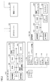
- FIG. 1 is a diagram illustrating an example of a configuration of a watching system.
- FIG. 1 is a block diagram illustrating an outline of a configuration of a watching system.
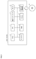
- FIG. 3 is a block diagram illustrating a hardware configuration of a computer system 300 functioning as a cloud server 150. It is a figure showing an example of the outline of the device composition of watching system 100 using sensor box 119.
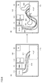
- FIG. 3 is a diagram illustrating one mode of data storage in a hard disk 5 included in the cloud server 150. It is a figure showing change of a walking locus of a resident in a certain situation.
- FIG. 3 is a diagram illustrating one mode of data storage in a hard disk 5.
- FIG. 3 is a diagram illustrating an example of a display on a monitor 8. It is a figure showing an example of a diagnosis report of a walking speed.
- ⁇ ⁇ ⁇ ⁇ In certain situations, normalize the observation values (walking speed, etc.) of the target person such as the resident of the facility. Using normalized observations, all subjects can be evaluated on the same basis.
- the degree of care required of the resident is determined based on a comparison of values obtained by normalizing each walking speed calculated based on walking trajectory data acquired on a plurality of different days.
- the walking speed is calculated using the walking locus data of each resident selected by the user, and the normalized walking speed is calculated by multiplying by the attribute coefficient.
- FIG. 1 is a diagram illustrating an example of the configuration of the watching system 100.
- the watching target is, for example, a resident in each living room provided in the living room area 180 of the facility.
- living rooms 110 and 120 are provided in a living room area 180.
- the living room 110 is assigned to the resident 111.
- the living room 120 is assigned to the resident 121.
- the number of living rooms included in the watching system 100 is two, but the number is not limited to this.
- Network 190 may include both an intranet and the Internet.
- the mobile terminal 143 carried by the caregiver 141 and the mobile terminal 144 carried by the caregiver 142 can be connected to the network 190 via the access point 140. Further, the sensor box 119, the management server 200, and the access point 140 can communicate with the cloud server 150 via the network 190.
- Each of the living rooms 110 and 120 includes a closet 112, a bed 113, and a toilet 114 as facilities.
- the door of the living room 110 is provided with a door sensor 118 that detects opening and closing of the door.
- a toilet sensor 116 for detecting the opening and closing of the toilet 114 is installed on the door of the toilet 114.
- the bed 113 is provided with an odor sensor 117 for detecting the odor of each of the residents 111 and 121.
- Each resident 111, 121 is equipped with a vital sensor 290 for detecting vital information of the resident 111, 121.
- the detected vital information includes the resident's body temperature, respiration, heart rate, and the like.
- the residents 111 and 121 can operate the care call slave 115, respectively.
- the sensor box 119 has a built-in sensor for detecting the behavior of an object in the living rooms 110 and 120.
- a sensor is a Doppler sensor for detecting the movement of an object.
- a camera is another example.
- the sensor box 119 may include both a Doppler sensor and a camera as sensors.
- FIG. 2 is a block diagram showing an outline of the configuration of the watching system 100.
- the sensor box 119 includes a control device 101, a read only memory (ROM) 102, a random access memory (RAM) 103, a communication interface 104, a camera 105, a Doppler sensor 106, a wireless communication device 107, and a storage device. 108.
- the control device 101 controls the sensor box 119.
- the control device 101 is composed of, for example, at least one integrated circuit.
- the integrated circuit is, for example, at least one CPU (Central Processing Unit), MPU (Micro Processing Unit) or other processor, at least one ASIC (Application Specific Integrated Circuit), at least one FPGA (Field Programmable Gate Array), or these. And the like.
- An antenna (not shown) and the like are connected to the communication interface 104.
- the sensor box 119 exchanges data with an external communication device via the antenna.
- External communication devices include, for example, management server 200, mobile terminals 143, 144 and other terminals, access point 140, cloud server 150, and other communication terminals.
- the camera 105 is a near-infrared camera in one implementation.
- the near-infrared camera includes an IR (Infrared) projector that emits near-infrared light.
- IR Infrared
- camera 105 is a surveillance camera that receives only visible light.
- a 3D sensor or a thermographic camera may be used as camera 105.
- the sensor box 119 and the camera 105 may be configured integrally or may be configured separately.
- the Doppler sensor 106 is, for example, a microwave Doppler sensor, and emits and receives radio waves to detect the behavior (movement) of objects in the living rooms 110 and 120. Thereby, the biological information of the resident 111, 121 of the living room 110, 120 can be detected.
- the Doppler sensor 106 emits microwaves in the 24 GHz band toward the beds 113 of the rooms 110 and 120, and receives reflected waves reflected by the residents 111 and 121. The reflected waves are Doppler shifted by the actions of the residents 111 and 121.
- the Doppler sensor 106 can detect the respiratory state and heart rate of the residents 111 and 121 from the reflected waves.
- the wireless communication device 107 receives signals from the care call slave device 240, the door sensor 118, the toilet sensor 116, the odor sensor 117, and the vital sensor 290, and transmits the signals to the control device 101.
- the care call slave unit 240 includes a care call button 241. When the button is operated, care call slave device 240 transmits a signal indicating that the operation has been performed to wireless communication device 107.
- the door sensor 118, the toilet sensor 116, the odor sensor 117, and the vital sensor 290 transmit respective detection results to the wireless communication device 107.
- the storage device 108 is, for example, a fixed storage device such as a flash memory or a hard disk, or a recording medium such as an external storage device.
- the storage device 108 stores a program executed by the control device 101 and various data used for executing the program.
- the various data may include behavior information of the residents 111 and 121. The details of the action information will be described later.
- At least one of the above-mentioned programs and data is a storage device other than the storage device 108 (for example, a storage area (for example, a cache memory) of the control device 101, a ROM 102, The RAM 103 and external devices (for example, the management server 200 and the portable terminals 143 and 144) may be stored.
- a storage device other than the storage device 108 for example, a storage area (for example, a cache memory) of the control device 101, a ROM 102,
- the RAM 103 and external devices for example, the management server 200 and the portable terminals 143 and 144) may be stored.
- the action information is, for example, information indicating that the residents 111 and 121 have performed a predetermined action.
- the predetermined action is “wake up” indicating that the resident 111, 121 has occurred, “getting out” indicating that the resident 111, 121 has left the bedding, and the resident 111, 121 has fallen from the bedding. This includes four actions of “fall” indicating that the resident has fallen, and “falling” indicating that the resident 111 or 121 has fallen.
- the control device 101 generates each piece of behavior information of the resident 111, 121 associated with each room 110, 120 based on an image captured by the camera 105 installed in each room 110, 120. I do.
- the control device 101 detects, for example, the heads of the residents 111 and 121 from the image, and based on the detected temporal changes in the sizes of the heads of the residents 111 and 121, “ “Wake up”, “get out of bed”, “fall” and “fall” are detected.
- “Wake up”, “get out of bed”, “fall” and “fall” are detected.
- the storage area of the beds 113 in the living rooms 110 and 120, the first threshold Th1, the second threshold Th2, and the third threshold Th3 are stored in the storage device.
- the first threshold Th1 identifies the size of the resident's head between the lying position and the sitting position in the area where the bed 113 is located.
- the second threshold value Th2 identifies whether or not the resident is in the standing posture, based on the size of the resident's head in the living rooms 110 and 120 excluding the area where the bed 113 is located.
- the third threshold value Th3 identifies whether or not the resident is in the recumbent posture in the living rooms 110 and 120 excluding the area where the bed 113 is located, based on the size of the resident's head.
- the control device 101 extracts a moving object region from the target image as a region of the occupants 111 and 121 by, for example, the background difference method or the frame difference method.
- the control device 101 further derives from the extracted moving body region by, for example, a circular or elliptical Hough transform, by pattern matching using a prepared head model, or by a neural network learned for head detection.
- the head areas of the residents 111 and 121 are extracted using the thresholds thus set.
- the control device 101 detects “wake up”, “get out of bed”, “fall” and “fall” from the extracted position and size of the head.
- the control device 101 determines that the position of the head extracted as described above is within the area where the bed 113 is located, and that the size of the head extracted as described above uses the first threshold Th1 to lie down. When it is detected that the size of the posture has changed to the size of the sitting posture, it may be determined that the action “wake up” has occurred.
- the control device 101 controls the size of the head extracted as described above.
- the control device 101 controls the size of the head extracted as described above.
- the control device 101 determines that the position of the head extracted as described above is located in the living rooms 110 and 120 excluding the area where the bed 113 is located, and the size of the extracted head uses the third threshold Th3. If it is detected that the size has changed from a certain size to the size of the recumbent posture, it may be determined that the action “fall” has occurred.
- the control device 101 of the sensor box 119 generates the behavior information of the residents 111 and 121.
- an element other than the control device 101 for example, the cloud server 150
- the cloud server 150 generates the behavior information of the residents 111 and 121 using the images in the living rooms 110 and 120. Is also good.
- the mobile terminals 143 and 144 include a control device 221, a ROM 222, a RAM 223, a communication interface 224, a display 226, a storage device 228, and an input device 229.
- the mobile terminals 143 and 144 are realized as, for example, a smartphone, a tablet terminal, a wristwatch-type terminal, or other wearable devices.
- the control device 221 controls the mobile terminals 143 and 144.
- the control device 221 is configured by, for example, at least one integrated circuit.
- the integrated circuit includes, for example, at least one CPU, at least one ASIC, at least one FPGA, or a combination thereof.
- An antenna (not shown) and the like are connected to the communication interface 224.
- the mobile terminals 143 and 144 exchange data with an external communication device via the antenna and the access point 140.
- External communication devices include, for example, the sensor box 119, the management server 200, and the like.
- the display 226 is realized by, for example, a liquid crystal display, an organic EL (Electro Luminescence) display, or the like.
- the input device 229 is realized by, for example, a touch sensor provided on the display 226. The touch sensor receives a touch operation on the mobile terminals 143 and 144, and outputs a signal corresponding to the touch operation to the control device 221.
- the storage device 228 is realized by, for example, a flash memory, a hard disk or another fixed storage device, or a removable data recording medium.
- FIG. 3 is a block diagram illustrating a hardware configuration of computer system 300 functioning as cloud server 150.
- the computer system 300 includes, as main components, a CPU 1 that executes a program, a mouse 2 and a keyboard 3 that receive an instruction input by a user of the computer system 300, and data generated by executing the program by the CPU 1 or a mouse 2.
- a RAM 4 for volatilely storing data input via the keyboard 3
- a hard disk 5 for nonvolatilely storing data
- an optical disk drive 6 a communication interface (I / F) 7, and a monitor 8 Including.
- Each component is mutually connected by a data bus.
- the optical disk drive 6 is loaded with a CD-ROM 9 and other optical disks.
- the processing in the computer system 300 is realized by each hardware and software executed by the CPU 1.
- Such software may be stored in the hard disk 5 in advance.
- the software may be stored on the CD-ROM 9 or another recording medium and distributed as a computer program.
- the software may be provided as a downloadable application program by an information provider connected to the so-called Internet.
- Such software is temporarily stored in the hard disk 5 after being read from the recording medium by the optical disk drive 6 or another reading device, or downloaded via the communication interface 7.
- the software is read from the hard disk 5 by the CPU 1 and stored in the RAM 4 in the form of an executable program.
- CPU 1 executes the program.
- Each component of the computer system 300 shown in FIG. 3 is a general component. Therefore, it can be said that one of the essential parts of the technical idea according to the present disclosure is software stored in the RAM 4, the hard disk 5, the CD-ROM 9, or other recording media, or software downloadable via a network.
- the storage medium may include a non-transitory, computer-readable data storage medium. Since the operation of each piece of hardware of computer system 300 is well known, detailed description will not be repeated.
- the recording medium is not limited to a CD-ROM, FD (Flexible Disk), or hard disk, but may be a magnetic tape, cassette tape, optical disk (MO (Magnetic Optical Disc) / MD (Mini Disc) / DVD (Digital Versatile Disc)). , IC (Integrated Circuit) card (including memory card), optical card, mask ROM, EPROM (Electronically Programmable Read-Only Memory), EEPROM (Electronically Erasable Programmable Read-Only Memory), and fixed memory such as flash ROM It may be a medium that carries the program.
- IC Integrated Circuit
- the program here includes not only a program directly executable by the CPU but also a program in a source program format, a compressed program, an encrypted program, and the like.
- FIG. 4 is a diagram illustrating an example of a schematic device configuration of the watching system 100 using the sensor box 119.
- the watching system 100 is used for watching the residents 111 and 121 who are the monitoring target (monitoring target) and other residents. As shown in FIG. 4, a sensor box 119 is attached to the ceiling of the living room 110. Sensor boxes 119 are similarly attached to other rooms.
- a range 410 represents a detection range of the sensor box 119.
- the Doppler sensor detects a person's behavior that has occurred within the range 410.
- the sensor box 119 has a camera as a sensor, the camera captures an image in the range 410.
- the sensor box 119 is installed in, for example, a nursing care facility, a medical facility, or a home.
- the sensor box 119 is attached to the ceiling, and the resident 111 and the bed 113 are imaged from the ceiling.
- the place where the sensor box 119 is mounted is not limited to the ceiling, and may be mounted on the side wall of the living room 110.
- the watching system 100 detects a danger occurring to the resident 111 based on a series of images (that is, videos) obtained from the camera 105.
- the detectable danger includes a fall of the resident 111 and a state where the resident 111 is at a danger location (for example, a bed fence).
- the monitoring system 100 When the monitoring system 100 detects that the resident 111 is in danger, the monitoring system 100 notifies the caregivers 141, 143, etc. of that fact. As an example of the notification method, the watching system 100 notifies the danger of the resident 111 to the portable terminals 143 and 144 of the caregivers 141 and 142. Upon receiving the notification, the mobile terminals 143 and 144 notify the caregivers 141 and 142 of the danger of the resident 111 by a message, voice, vibration, or the like. Accordingly, the caregivers 141 and 142 can immediately recognize that the danger has occurred in the resident 111 and can rush to the resident 111 quickly.
- FIG. 4 illustrates an example in which the watching system 100 includes one sensor box 119, but the watching system 100 may include a plurality of sensor boxes 119.
- FIG. 4 shows an example in which the watching system 100 includes a plurality of mobile terminals 143 and 144. However, the watching system 100 can be realized by one mobile terminal.
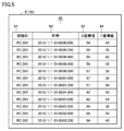
- FIG. 5 is a diagram illustrating one mode of data storage in the hard disk 5 included in the cloud server 150.
- the hard disk 5 holds the table 60.
- the table 60 sequentially stores data transmitted from each sensor provided in each living room as walking locus data. More specifically, the table 60 includes a room ID 61, a date and time 62, an X coordinate value 63, and a Y coordinate value 64.
- the room ID 61 identifies the room of the resident.
- the date and time 62 identifies the date and time when the signal sent from the sensor was acquired.
- the X coordinate value 63 indicates the point detected at the date and time, that is, the X coordinate value of the position of the resident.
- the Y coordinate value 64 represents the point detected at the date and time, that is, the Y coordinate value of the position of the resident.
- the coordinate axes that are the basis of the X coordinate value and the Y coordinate value are defined, for example, with reference to the end point of the living room (for example, one corner of the room).
- the coordinate axis may be defined based on a certain point in the facility where each living room is provided.
- the hard disk 5 holds the image data sent from the sensor box 119.
- Image data is acquired at predetermined time intervals.
- the CPU 1 can identify the state of the resident by performing image analysis using each image data. For example, the CPU 1 can extract a head from each image data and extract a time when the resident is lying down, a time when the resident is sitting on the bed 113, and a time when the resident is walking.
- the person who walks in the room may be a caregiver or a family other than the resident. Therefore, the CPU 1 can exclude a walking locus of a person other than the resident.
- the CPU 1 may calculate a walking speed for each walking locus, and exclude a walking locus whose speed is equal to or higher than a certain speed estimated to be a walking speed of a healthy person other than a resident from image analysis targets.
- a walking speed measured in advance or a walking speed measured at the time of image analysis can be used as a walking speed of a healthy person.
- the CPU 1 calculates, for each point detected at a plurality of times, an x-coordinate value and a y-coordinate value, and a next point from a certain point in each point. Can be calculated based on the time required to reach.
- the CPU 1 indicates a walking locus of a resident and reads a plurality of walking locus data acquired on different days from the hard disk 5.
- the CPU 1 calculates a walking speed of the resident based on a plurality of walking trajectory data. For example, for each walking locus, the CPU 1 calculates the difference between the x coordinate value and the y coordinate value of the two observed points, and divides the time required for movement between the two points by the difference. Calculate the walking speed.
- the walking locus data to be calculated is not particularly limited.
- the walking locus data acquired the day before the day on which the calculation was instructed the walking locus data acquired three months before the previous day, and the walking locus data acquired six months before the previous day are used. May be done.
- the period for seeing the change in walking speed is not limited to three months and six months ago. Walking trajectory data one month ago and two months ago may be used. Alternatively, walking locus data one year ago may be used.
- the CPU 1 normalizes the walking speed by multiplying the walking speed by a predetermined coefficient based on the attribute of the resident.
- Normalized value calculated walking speed ⁇ coefficient according to first attribute ⁇ ... ⁇ coefficient according to n-th attribute (2)
- the attributes of the resident are age, gender, height, Or include either weight.
- the normalized walking speed is calculated as follows as an example.
- Normalized walking speed measured walking speed ⁇ age coefficient ⁇ sex coefficient ⁇ height coefficient ⁇ weight coefficient (3)
- the CPU 1 is calculated based on walking locus data acquired on a plurality of different days. Based on the comparison of the respective values obtained by normalizing the respective walking speeds, the degree of care required of the resident is determined.
- the CPU 1 calculates a walking speed using the walking locus data of each resident selected by the user, and calculates a normalized walking speed by multiplying by a coefficient according to the attribute. By comparing the normalized values, the CPU 1 can detect the presence or absence of a change in the state of each resident and the degree of the change.
- FIG. 6 is a diagram illustrating a change in a walking locus of a resident in a certain situation.
- each walking locus 610, 611 shows a reciprocating locus from the bed 113 to the toilet 114. Therefore, it is presumed that the resident went straight from bed 113 to toilet 114. For example, when the resident does not have difficulty walking or does not develop dementia or the like, even at night, the path from the bed 113 to the toilet 114 takes the walking locus 610 so as to take the shortest course. , 611.
- the resident may walk without purpose (wandering).
- walking trajectories 622 and 623 that are not directed to a specific destination (for example, the wash basin 51, the closet 112, the desk 52, etc.) can be observed. Therefore, by observing the change in the walking locus of each resident, it is possible to objectively grasp the change in the state of the resident. For example, if it is detected that the walking trajectory, which has been almost straight from the bed 113 to the destination in the past, fluctuates or goes around the same place, it is estimated that the state of the resident has changed. .
- FIG. 7 is a diagram illustrating one mode of data storage in hard disk 5.
- the data structure shown in FIG. 7 is generated on the hard disk 5 of the cloud server 150 or the management server 200.
- the hard disk 5 has tables 710, 720, and 730.
- the table 710 includes an age 711 and an age coefficient 712.
- the age 711 is classified every several years.
- the width of the age 711 is not limited to that illustrated in FIG. For example, it may be in units of two or three years or ten years.
- Table 720 includes gender 721 and gender coefficient 722.
- the gender 721 is applied to the gender of the resident.
- the gender coefficient 722 is applied according to the gender of the resident.
- Table 730 includes height 731 and height coefficient 732.
- the height 731 indicates the height of the resident.
- the width of the height is not limited to the example (10 cm) shown in FIG. 7 and may be another width, for example, 2 cm, 5 cm, or the like.
- Height coefficient 732 represents a coefficient applied to each height.
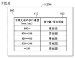
- FIG. 8 is a diagram showing the correspondence between the walking speed and the level of the need for nursing care or support required according to the walking speed.
- the hard disk 5 includes the table 800.
- the table 800 includes the normalized walking speed 810 and the degree of care / support required 820.
- the normalized walking speed 810 is a walking speed calculated by multiplying by a weight coefficient corresponding to each attribute shown in FIG.
- the degree of need for nursing / support required 820 indicates the degree of need for nursing or support required according to the walking speed.
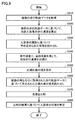
- FIG. 9 is a flowchart showing a part of the process executed by CPU 1 of cloud server 150.
- step S910 the CPU 1 acquires a plurality of walking trajectory data from the hard disk 5 based on the instruction of the data processing being given to the cloud server 150. For example, when a user (administrator, nursing staff, etc.) of the management server 200 accessing the cloud server 150 instructs data processing, the cloud server 150 stores the stored walking trajectory data (see FIG. 5). The data is read from the hard disk 5 to the RAM 4.
- step S920 CPU 1 calculates the walking speed of the resident based on the plurality of walking trajectory data.
- the CPU 1 uses the walking locus data observed at a designated time such as morning, afternoon, before going to bed, etc., and moves in using the time required for the movement of two points and the coordinate values of the two points.
- the walking speed of the person is calculated.
- Data serving as a basis for calculating the walking speed may be any of image data acquired by the camera 105 and data output from the Doppler sensor 106.
- CPU 1 reads out a coefficient (FIG. 7) predetermined based on the attribute of the resident.
- each coefficient may be input by the user each time during the normalization process.
- step S940 the CPU 1 normalizes the walking speed by multiplying the walking speed by the coefficient.
- the CPU 1 normalizes the walking speed using the formula “calculated walking speed ⁇ age coefficient ⁇ sex coefficient ⁇ height coefficient”. Note that all the coefficients shown in FIG. 7 need not be used as the coefficients used for normalization, and other coefficients than those shown in FIG. 7 may be used.
- step S950 CPU 1 stores the normalized value in hard disk 5.
- step S960 CPU 1 reads the normalized values calculated based on the walking trajectory data acquired on a plurality of different days. At this time, the CPU 1 may read the values of each of the plurality of residents selected by the user.
- CPU 1 compares each value. For example, the CPU 1 compares the normalized values of one resident three days before and six months before the tenant's day. In a case where a plurality of residents are selected in another aspect, similarly, for each of the residents, the values after the normalization on the day before, three months before, and six months before the residents are compared. Further, the CPU 1 can display each value on the monitor 8 as a graph.
- CPU 1 determines the state of the resident based on the result of the comparison. For example, if the CPU 1 detects a resident whose walking speed is significantly reduced, the CPU 1 displays on the monitor 8 a determination result such as “check of nursing care required” or “requirement of detailed inspection”. Alternatively, it may be output to a form as a diagnosis result.
- FIG. 10 is a diagram illustrating an example of a display on the monitor 8.
- the monitor 8 displays a graph 1010 of Mr. A and a graph 1020 of Mr. B based on the data before the normalization.
- the monitor 8 displays a graph 1011 of Mr. A and a graph 1021 of Mr. B based on the normalized data.
- the walking speed of Mr. B is higher than the walking speed of Mr. A
- the degree of decrease in the walking ability of Mr. A is larger than the degree of the walking ability of Mr. B. It is understood.
- FIG. 11 is a diagram showing an example of a walking speed diagnosis report.
- the monitor 8 displays a diagnostic report based on FIG.
- the monitor 8 displays the attributes of the selected resident, the diagnosis result, and the like. Is displayed.
- the monitor 8 may display a notice such as "check of degree of nursing care required", "requirement of detailed inspection” or the like for a resident requiring special attention. Thereby, the user can take necessary measures according to the degree of change of the resident.
- a measured value for example, walking speed
- a coefficient defined in accordance with the attribute of a resident a state in which an influence due to a difference in attribute is excluded.
- the state and ability eg, walking ability
- the status of each resident can be objectively grasped, and the status of each resident can be compared without being affected by the attribute, so that the status of each resident can be grasped more accurately.
- This technology is applicable to information processing using data obtained in hospitals, nursing homes, nursing homes and other facilities.
Landscapes
- Health & Medical Sciences (AREA)
- Business, Economics & Management (AREA)
- Engineering & Computer Science (AREA)
- Physics & Mathematics (AREA)
- Life Sciences & Earth Sciences (AREA)
- General Physics & Mathematics (AREA)
- Biomedical Technology (AREA)
- General Health & Medical Sciences (AREA)
- Primary Health Care (AREA)
- Public Health (AREA)
- General Business, Economics & Management (AREA)
- Medical Informatics (AREA)
- Tourism & Hospitality (AREA)
- Emergency Management (AREA)
- Surgery (AREA)
- Dentistry (AREA)
- Heart & Thoracic Surgery (AREA)
- Animal Behavior & Ethology (AREA)
- Pathology (AREA)
- Biophysics (AREA)
- Veterinary Medicine (AREA)
- Oral & Maxillofacial Surgery (AREA)
- Epidemiology (AREA)
- Molecular Biology (AREA)
- Child & Adolescent Psychology (AREA)
- Physiology (AREA)
- Economics (AREA)
- Human Resources & Organizations (AREA)
- Marketing (AREA)
- Strategic Management (AREA)
- Theoretical Computer Science (AREA)
- Medical Treatment And Welfare Office Work (AREA)
- Alarm Systems (AREA)
Abstract
コンピューターシステムのCPUが実行する処理は、ハードディスクから歩行軌跡データを取得するステップ(S910)と、複数の歩行軌跡データに基づいて、当該入居者の歩行速度を算出するステップ(S920)と、入居者の属性に基づいて予め定められた係数を読み出すステップ(S930)と、歩行速度に、当該係数を乗じて、当該歩行速度を正規化するステップ(S940)と、正規化後の値を保存するステップ(S950)と、複数の異なる日に取得された歩行軌跡データに基づいて算出された正規化後の値を読み出すステップ(S960)と、各値を比較するステップ(S970)と、比較の結果に基づいて当業者の状態を判定するステップ(S980)とを含む。
Description
本開示はデータ処理に関し、より特定的には、歩行軌跡に基づくデータ処理に関する。
居住者を見守る技術が知られている。例えば、特開2015-215711号公報(特許文献1)は、『居住者の生活に寄り添う形で居住者の行動や生態の相対的な変化を見守るべく、個人差が著しい「老い」の進行を、その居住者の能力や環境に応じて相対的に評価しその評価に合った見守りの仕様を提示できる見守りシステム』を開示している([要約]の[課題]参照)。
特開2017-117423号公報(特許文献2)は、『見守り対象者の歩速を含む日常行動を把握可能な見守りシステム』を開示している。当該見守りシステムは、『住居Hに設置された複数の子機2(2A~2G)と親機3とを備える。各子機2は、対象者を感知すると通知信号を親機3に送信する。親機3は、子機2Dからの通知信号の時刻データと子機2Eからの通知信号の時刻データとに基づいて、見守り対象者の寝室PDからトイレPDまでの移動時間を算出し、当該移動時間に基づき見守り対象者の歩速を算出する。』という構成を備える([要約]参照)。
見守りや介護を必要とする人について、介護度の認定は、例えば、対象者、介護者への聞き取りや主治医の意見等に基づいて行なわれ、定量的な測定ができず、要介護度の判定に時間がかかる場合がある。また、測定値は、入居している期間に応じて変化する場合もある。そして、測定値(例えば、歩行速度等)の変化の度合いは、入居者の体格、年齢、性別等で異なる。そのため、測定値のみを単純に比較しただけでは、入居者の状態の変化が適正に把握できない場合がある。したがって、入居者の状態の変化を適正に把握できる技術が必要とされている。
本開示は上述のような背景に鑑みてなされたものであって、ある局面における目的は、入居者の状態の変化を適正に把握できる技術を提供することである。
ある実施の形態に従うと、コンピュータで実行されるプログラムが提供される。プログラムはコンピュータに、入居者の歩行軌跡を表わす歩行軌跡データを取得するステップと、複数の歩行軌跡データに基づいて、当該入居者の歩行速度を算出するステップと、入居者の属性に基づいて予め定められた係数に基づいて、歩行速度を正規化するステップとを実行させる。
ある実施の形態に従うと、入居者の属性は、年齢、性別、身長、または体重のいずれかを含む。
ある実施の形態に従うと、プログラムはコンピュータに、複数の異なる日に取得された歩行軌跡データに基づいて算出された各歩行速度を正規化した各値の比較に基づいて、当該入居者の要介護度を判定するステップをさらに実行させる。
他の実施の形態に従うと、情報処理装置が提供される。情報処理装置は、メモリーと、メモリーに結合されたプロセッサーとを備える。プロセッサーは、入居者の歩行軌跡を表わす歩行軌跡データを取得し、複数の歩行軌跡データに基づいて、当該入居者の歩行速度を算出し、歩行速度に、入居者の属性に基づいて予め定められた係数に基づいて、歩行速度を正規化するように構成されている。
他の実施の形態に従う情報処理装置において、入居者の属性は、年齢、性別、身長、または体重のいずれかを含む。
他の実施の形態に従うと、プロセッサーは、複数の異なる日に取得された歩行軌跡データに基づいて算出された各歩行速度を正規化した各値の比較に基づいて、当該入居者の要介護度を判定するようにさらに構成されている。
さらに他の実施の形態に従うと、コンピュータで実行される方法が提供される。この方法は、入居者の歩行軌跡を表わす歩行軌跡データを取得するステップと、複数の歩行軌跡データに基づいて、当該入居者の歩行速度を算出するステップと、入居者の属性に基づいて予め定められた係数に基づいて、歩行速度を正規化するステップとを含む。
他の実施の形態に従う方法において、入居者の属性は、年齢、性別、身長、または体重のいずれかを含む。
さらに他の実施の形態に従うと、方法は、複数の異なる日に取得された歩行軌跡データに基づいて算出された各歩行速度を正規化した各値の比較に基づいて、当該入居者の要介護度を判定するステップをさらに含む。
本開示のコンピューターで実行されるプログラム、情報処理装置、および、コンピューターで実行される方法は、入居者の状態の変化を適正に把握できる。
この発明の上記および他の目的、特徴、局面および利点は、添付の図面と関連して理解されるこの発明に関する次の詳細な説明から明らかとなるであろう。
以下、図面を参照しつつ、本開示に係る技術思想の実施の形態について説明する。以下の説明では、同一の部品には同一の符号を付してある。それらの名称および機能も同じである。したがって、それらについての詳細な説明は繰り返さない。
[技術思想]
本明細書に開示にされる技術思想の概要について説明する。
本明細書に開示にされる技術思想の概要について説明する。
ある局面において、施設の入居者等の対象者の観測値(歩行速度など)を正規化する。正規化した観測値を使って、全ての対象者を同じ基準で評価することが可能である。
例えば、歩行速度が70cm/sの人(Aさん)と、30cm/sの人(Bさん)がいて、Aさんの歩行速度が5cm/s下がるのと、Bさんの歩行速度が5cm/s下がるのでは捉え方が異なる。オフセットを使って下がり方の違いを正規化する。これにより入居者等の対象者の要介護度の判定が容易になる。
別の局面において、年齢、性別、体格(身長あるいは体重)によって正規化の係数を決めるテーブルを準備する。それぞれから出した係数を用いることで、年齢、性別、身長あるいは体重に関係しない正規化された値を得るようにする。
さらに別の局面において、複数の異なる日に取得された歩行軌跡データに基づいて算出された各歩行速度を正規化した各値の比較に基づいて、当該入居者の要介護度を判定する。ユーザーによって選択された各入居者の歩行軌跡データを用いて歩行速度を算出し、属性係数を乗じて正規化後の歩行速度を算出する。正規化後の値を比較することにより、各入居者の状態の変化の有無および変化の度合いを検出する。
[見守りシステムの構成]
図1は、見守りシステム100の構成の一例を示す図である。見守り対象は、例えば、施設の居室領域180に設けられた各居室内の入居者である。図1の見守りシステム100では、居室領域180に、居室110,120が設けられている。居室110は、入居者111に割り当てられている。居室120は、入居者121に割り当てられている。図1の例では、見守りシステム100に含まれる居室の数は2であるが、当該数はこれに限定されない。
図1は、見守りシステム100の構成の一例を示す図である。見守り対象は、例えば、施設の居室領域180に設けられた各居室内の入居者である。図1の見守りシステム100では、居室領域180に、居室110,120が設けられている。居室110は、入居者111に割り当てられている。居室120は、入居者121に割り当てられている。図1の例では、見守りシステム100に含まれる居室の数は2であるが、当該数はこれに限定されない。
見守りシステム100では、居室110,120にそれぞれ設置されたセンサーボックス119と、管理センター130に設置された管理サーバー200と、アクセスポイント140とが、ネットワーク190を介して接続される。ネットワーク190は、イントラネットおよびインターネットのいずれをも含み得る。
見守りシステム100では、介護者141が携帯する携帯端末143、および、介護者142が携帯する携帯端末144は、アクセスポイント140を介してネットワーク190に接続可能である。さらに、センサーボックス119、管理サーバー200、および、アクセスポイント140は、ネットワーク190を介して、クラウドサーバー150と通信可能である。
居室110,120は、それぞれ、設備として、タンス112、ベッド113、および、トイレ114を含む。居室110のドアには、当該ドアの開閉を検出するドアセンサー118が設置されている。トイレ114のドアには、トイレ114の開閉を検出するトイレセンサー116が設置されている。ベッド113には、各入居者111,121の臭いを検出する臭いセンサー117が設置されている。各入居者111,121は、当該入居者111,121のバイタル情報を検出するバイタルセンサー290を装着している。検出されるバイタル情報は、入居者の体温、呼吸、心拍数等を含む。居室110,120では、各入居者111,121は、それぞれ、ケアコール子機115を操作することができる。
センサーボックス119は、居室110,120内の物体の挙動を検出するためのセンサーを内蔵している。センサーの一例は、物体の動作を検出するためのドップラーセンサーである。他の例は、カメラである。センサーボックス119は、センサーとしてドップラーセンサーとカメラの双方を含んでもよい。
図2を参照して、見守りシステム100の構成要素について説明する。図2は、見守りシステム100の構成の概要を示すブロック図である。
[センサーボックス119]
センサーボックス119は、制御装置101と、ROM(Read Only Memory)102と、RAM(Random Access Memory)103と、通信インターフェイス104と、カメラ105と、ドップラーセンサー106と、無線通信装置107と、記憶装置108とを備える。
センサーボックス119は、制御装置101と、ROM(Read Only Memory)102と、RAM(Random Access Memory)103と、通信インターフェイス104と、カメラ105と、ドップラーセンサー106と、無線通信装置107と、記憶装置108とを備える。
制御装置101は、センサーボックス119を制御する。制御装置101は、たとえば、少なくとも1つの集積回路によって構成される。集積回路は、たとえば、少なくとも1つのCPU(Central Processing Unit)、MPU(Micro Processing Unit)その他のプロセッサー、少なくとも1つのASIC(Application Specific Integrated Circuit)、少なくとも1つのFPGA(Field Programmable Gate Array)、またはこれらの組み合わせなどによって構成される。
通信インターフェイス104には、アンテナ(図示しない)などが接続される。センサーボックス119は、当該アンテナを介して、外部の通信機器との間でデータをやり取りする。外部の通信機器は、たとえば、管理サーバー200、携帯端末143,144その他の端末、アクセスポイント140、クラウドサーバー150、その他の通信端末などを含む。
カメラ105は、一実現例では、近赤外カメラである。近赤外カメラは、近赤外光を投光するIR(Infrared)投光器を含む。近赤外カメラが用いられることにより、夜間でも居室110,120の内部を表わす画像が撮影され得る。他の実現例では、カメラ105は、可視光のみを受光する監視カメラである。さらに他の実現例では、カメラ105として、3Dセンサやサーモグラフィーカメラが用いられてもよい。センサーボックス119およびカメラ105は、一体として構成されてもよいし、別体で構成されてもよい。
ドップラーセンサー106は、たとえばマイクロ波ドップラーセンサーであり、電波を放射及び受信して、居室110,120内の物体の挙動(動作)を検出する。これにより、居室110,120の入居者111,121の生体情報が検出され得る。一例では、ドップラーセンサー106は、24GHz帯のマイクロ波を各居室110,120のベッド113に向けて放射し、入居者111,121で反射した反射波を受信する。反射波は、入居者111,121の動作により、ドップラーシフトしている。ドップラーセンサー106は、当該反射波から、入居者111,121の呼吸状態や心拍数を検出し得る。
無線通信装置107は、ケアコール子機240、ドアセンサー118、トイレセンサー116、臭いセンサー117、および、バイタルセンサー290からの信号を受信し、当該信号を制御装置101へ送信する。たとえば、ケアコール子機240は、ケアコールボタン241を備える。当該ボタンが操作されると、ケアコール子機240は、当該操作があったことを示す信号を無線通信装置107へ送信する。ドアセンサー118、トイレセンサー116、臭いセンサー117、および、バイタルセンサー290は、それぞれの検出結果を無線通信装置107へ送信する。
記憶装置108は、たとえば、フラッシュメモリーまたはハードディスク等の固定記憶装置、あるいは、外付けの記憶装置などの記録媒体である。記憶装置108は、制御装置101によって実行されるプログラム、および、当該プログラムの実行に利用される各種のデータを格納する。各種のデータは、入居者111,121の行動情報を含んでいてもよい。行動情報の詳細は後述する。
上記のプログラムおよびデータのうち少なくとも一方は、制御装置101がアクセス可能な記憶装置であれば、記憶装置108以外の記憶装置(たとえば、制御装置101の記憶領域(たとえば、キャッシュメモリーなど)、ROM102、RAM103、外部機器(たとえば、管理サーバー200や携帯端末143,144等)に格納されていてもよい。
[行動情報]
上記の行動情報について、説明する。行動情報は、たとえば入居者111,121が所定の行動を実行したことを表わす情報である。一例では、所定の行動は、入居者111,121が起きたことを表わす「起床」、入居者111,121が寝具から離れたことを表わす「離床」、入居者111,121が寝具から落ちたことを表わす「転落」、および、入居者111,121が倒れたことを表わす「転倒」の4つの行動を含む。
上記の行動情報について、説明する。行動情報は、たとえば入居者111,121が所定の行動を実行したことを表わす情報である。一例では、所定の行動は、入居者111,121が起きたことを表わす「起床」、入居者111,121が寝具から離れたことを表わす「離床」、入居者111,121が寝具から落ちたことを表わす「転落」、および、入居者111,121が倒れたことを表わす「転倒」の4つの行動を含む。
一実施の形態では、制御装置101が、各居室110,120に設置されたカメラ105が撮像した画像に基づいて、各居室110,120に関連付けられた入居者111,121の各行動情報を生成する。制御装置101は、たとえば、上記画像から入居者111,121の頭部を検出し、この検出した入居者111,121の頭部における大きさの時間変化に基づいて、入居者111,121の「起床」、「離床」、「転倒」および「転落」を検出する。以下、行動情報の生成の一具体例を、より詳細に説明する。
まず、記憶装置108に、居室110,120における各ベッド113の所在領域、第1閾値Th1、第2閾値Th2、および、第3閾値Th3が格納される。第1閾値Th1は、ベッド113の所在領域内において、横臥姿勢にあるときと座位姿勢にあるときとの間で入居者の頭部の大きさを識別する。第2閾値Th2は、ベッド113の所在領域を除く居室110,120内において、入居者の頭部の大きさに基づいて、当該入居者が立位姿勢にあるか否かを識別する。第3閾値Th3は、ベッド113の所在領域を除く居室110,120内において、入居者の頭部の大きさに基づいて、当該入居者が横臥姿勢にあるか否かを識別する。
制御装置101は、対象画像から、例えば背景差分法やフレーム差分法によって、入居者111,121の人物の領域として、動体領域を抽出する。制御装置101は、さらに、当該抽出した動体領域から、例えば円形や楕円形のハフ変換によって、予め用意された頭部のモデルを用いたパターンマッチングによって、頭部検出用に学習したニューラルネットワークによって導出された閾値を用いて、入居者111,121の頭部領域を抽出する。制御装置101は、当該抽出された頭部の位置および大きさから、「起床」、「離床」、「転倒」および「転落」を検知する。
制御装置101は、上記のように抽出された頭部の位置がベッド113の所在領域内にあり、かつ、上記のように抽出された頭部の大きさが第1閾値Th1を用いることによって横臥姿勢の大きさから座位姿勢の大きさへと変化したことを検出した場合に、行動「起床」が発生したことを決定してもよい。
制御装置101は、上記のように抽出された頭部の位置がベッド113の所在領域内からベッド113の所在領域外へ移動した場合において、上記のように抽出された頭部の大きさに対して第2閾値Th2を適用することにより、頭部がある大きさから立位姿勢の大きさへと変化したことを検出したときには、行動「離床」が発生したと判定してもよい。
制御装置101は、上記のように抽出された頭部の位置がベッド113の所在領域内からベッド113の所在領域外へ移動した場合において、上記のように抽出された頭部の大きさに対して第3閾値Th3を適用することにより、頭部がある大きさから横臥姿勢の大きさへと変化したことを検出したときには、行動「転落」が発生したと判定してもよい。
制御装置101は、上記のように抽出された頭部の位置がベッド113の所在領域を除く居室110,120内に位置し、かつ、抽出された頭部の大きさが第3閾値Th3を用いることによって或る大きさから横臥姿勢の大きさへと変化したことを検出した場合には、行動「転倒」が発生したと決定してもよい。
以上説明されたように、一具体例では、センサーボックス119の制御装置101が、入居者111,121の各行動情報を生成する。なお、他の局面に従う見守りシステム100では、居室110,120内の画像を用いて、制御装置101以外の他の要素(例えば、クラウドサーバー150)が入居者111,121の行動情報を生成してもよい。
[携帯端末143,144]
携帯端末143,144は、制御装置221と、ROM222と、RAM223と、通信インターフェイス224と、ディスプレイ226と、記憶装置228と、入力デバイス229とを含む。ある局面において、携帯端末143,144は、例えば、スマートフォン、タブレット端末、腕時計型端末その他のウェアラブル装置等として実現される。
携帯端末143,144は、制御装置221と、ROM222と、RAM223と、通信インターフェイス224と、ディスプレイ226と、記憶装置228と、入力デバイス229とを含む。ある局面において、携帯端末143,144は、例えば、スマートフォン、タブレット端末、腕時計型端末その他のウェアラブル装置等として実現される。
制御装置221は、携帯端末143,144を制御する。制御装置221は、たとえば、少なくとも1つの集積回路によって構成される。集積回路は、たとえば、少なくとも1つのCPU、少なくとも1つのASIC、少なくとも1つのFPGA、またはそれらの組み合わせなどによって構成される。
通信インターフェイス224には、アンテナ(図示しない)などが接続される。携帯端末143,144は、当該アンテナおよびアクセスポイント140を介して、外部の通信機器との間でデータをやり取りする。外部の通信機器は、たとえば、センサーボックス119、管理サーバー200などを含む。
ディスプレイ226は、たとえば液晶ディスプレイ、有機EL(Electro Luminescence)ディスプレイ等によって実現される。入力デバイス229は、たとえばディスプレイ226に設けられたタッチセンサーによって実現される。当該タッチセンサーは、携帯端末143,144に対するタッチ操作を受け付け、当該タッチ操作に応じた信号を制御装置221へ出力する。
記憶装置228は、たとえば、フラッシュメモリー、ハードディスクその他の固定記憶装置、あるいは、着脱可能なデータ記録媒体等により実現される。
[クラウドサーバーの構成]
図3を参照して、クラウドサーバー150の構成について説明する。図3は、クラウドサーバー150として機能するコンピューターシステム300のハードウェア構成を表わすブロック図である。
図3を参照して、クラウドサーバー150の構成について説明する。図3は、クラウドサーバー150として機能するコンピューターシステム300のハードウェア構成を表わすブロック図である。
コンピューターシステム300は、主たる構成要素として、プログラムを実行するCPU1と、コンピューターシステム300の使用者による指示の入力を受けるマウス2およびキーボード3と、CPU1によるプログラムの実行により生成されたデータ、又はマウス2若しくはキーボード3を介して入力されたデータを揮発的に格納するRAM4と、データを不揮発的に格納するハードディスク5と、光ディスク駆動装置6と、通信インターフェイス(I/F)7と、モニター8とを含む。各構成要素は、相互にデータバスによって接続されている。光ディスク駆動装置6には、CD-ROM9その他の光ディスクが装着される。
コンピューターシステム300における処理は、各ハードウェアおよびCPU1により実行されるソフトウェアによって実現される。このようなソフトウェアは、ハードディスク5に予め記憶されている場合がある。また、ソフトウェアは、CD-ROM9その他の記録媒体に格納されて、コンピュータープログラムとして流通している場合もある。あるいは、ソフトウェアは、いわゆるインターネットに接続されている情報提供事業者によってダウンロード可能なアプリケーションプログラムとして提供される場合もある。このようなソフトウェアは、光ディスク駆動装置6その他の読取装置によりその記録媒体から読み取られて、あるいは、通信インターフェイス7を介してダウンロードされた後、ハードディスク5に一旦格納される。そのソフトウェアは、CPU1によってハードディスク5から読み出され、RAM4に実行可能なプログラムの形式で格納される。CPU1は、そのプログラムを実行する。
図3に示されるコンピューターシステム300を構成する各構成要素は、一般的なものである。したがって、本開示に係る技術思想の本質的な部分の一つは、RAM4、ハードディスク5、CD-ROM9その他の記録媒体に格納されたソフトウェア、あるいはネットワークを介してダウンロード可能なソフトウェアであるともいえる。記録媒体は、一時的でない、コンピューター読取可能なデータ記録媒体を含み得る。なお、コンピューターシステム300の各ハードウェアの動作は周知であるので、詳細な説明は繰り返さない。
なお、記録媒体としては、CD-ROM、FD(Flexible Disk)、ハードディスクに限られず、磁気テープ、カセットテープ、光ディスク(MO(Magnetic Optical Disc)/MD(Mini Disc)/DVD(Digital Versatile Disc))、IC(Integrated Circuit)カード(メモリーカードを含む)、光カード、マスクROM、EPROM(Electronically Programmable Read-Only Memory)、EEPROM(Electronically Erasable Programmable Read-Only Memory)、フラッシュROMなどの半導体メモリー等の固定的にプログラムを担持する媒体でもよい。
ここでいうプログラムとは、CPUにより直接実行可能なプログラムだけでなく、ソースプログラム形式のプログラム、圧縮処理されたプログラム、暗号化されたプログラム等を含む。
[見守りシステム100の装置構成]
図4を参照して、見守りシステム100を用いた見守りについて説明する。図4は、センサーボックス119を用いた見守りシステム100の装置構成の概略の一例を示す図である。
図4を参照して、見守りシステム100を用いた見守りについて説明する。図4は、センサーボックス119を用いた見守りシステム100の装置構成の概略の一例を示す図である。
見守りシステム100は、見守り対象者(監視対象者)である入居者111,121その他の入居者を見守るために利用される。図4に示されるように、居室110の天井には、センサーボックス119が取り付けられている。他の居室にも同様にセンサーボックス119が取り付けられている。
範囲410は、センサーボックス119による検出範囲を表わす。センサーボックス119が前述のドップラーセンサーを有する場合、当該ドップラーセンサーは、範囲410内で生じた人の挙動を検出する。センサーボックス119がセンサーとしてカメラを有する場合、当該カメラは、範囲410内の画像を撮影する。
センサーボックス119は、たとえば、介護施設、医療施設、宅内などに設置される。図4の例では、センサーボックス119は、天井に取り付けられており、入居者111およびベッド113を天井から撮影している。センサーボックス119の取り付け場所は天井に限られず、居室110の側壁に取り付けられてもよい。
見守りシステム100は、カメラ105から得られた一連の画像(すなわち、映像)に基づいて入居者111に生じている危険を検知する。一例として、検知可能な危険は、入居者111の転倒や、危険個所(たとえば、ベッドの柵など)に入居者111がいる状態などを含む。
見守りシステム100は、入居者111に危険が生じていることを検知した場合に、そのことを介護者141,143等に報知する。報知方法の一例として、見守りシステム100は、入居者111の危険を介護者141,142の携帯端末143,144に通知する。携帯端末143,144は、当該通知を受信すると、入居者111の危険をメッセージ、音声、振動等で介護者141,142に報知する。これにより、介護者141,142は、入居者111に危険が生じていることを即座に把握でき、入居者111の元に素早く駆け付けることができる。
なお、図4には、見守りシステム100が1つのセンサーボックス119を備えている例が示されているが、見守りシステム100は、複数のセンサーボックス119を備えてもよい。また、図4には、見守りシステム100が複数の携帯端末143,144を備えている例が示されているが、見守りシステム100は、一つの携帯端末でも実現され得る。
[データ構造]
図5を参照して、クラウドサーバー150のデータ構造について説明する。図5は、クラウドサーバー150が備えるハードディスク5におけるデータの格納の一態様を表わす図である。
図5を参照して、クラウドサーバー150のデータ構造について説明する。図5は、クラウドサーバー150が備えるハードディスク5におけるデータの格納の一態様を表わす図である。
ハードディスク5は、テーブル60を保持している。テーブル60は、各居室に設けられた各センサーから送信されるデータを歩行軌跡データとして逐次保存している。より具体的には、テーブル60は、部屋ID61と、日時62と、X座標値63と、Y座標値64とを含む。部屋ID61は、入居者の居室を識別する。日時62は、センサーから送られた信号が取得された日時を識別する。X座標値63は、当該日時において検出された点、すなわち、入居者の位置のX座標値を表わす。Y座標値64は、当該日時において検出された点、すなわち、入居者の位置のY座標値を表わす。ある局面において、X座標値およびY座標値の元となる座標軸は、例えば、当該居室の端点(例えば、部屋の片隅)を基準として規定される。別の局面において、当該座標軸は、各居室が設けられた施設におけるある一点を基準として規定されてもよい。
さらに、ハードディスク5は、センサーボックス119から送られた画像データを保持している。画像データは予め定められた時間間隔で取得される。CPU1は、各画像データを用いて画像解析を行なうことにより、入居者の状態を識別することができる。例えば、CPU1は、各画像データから頭を抽出し、入居者が横になっている時間、入居者がベッド113に座っている時間、および、入居者が歩いている時間を抽出し得る。
なお、居室で歩行する人は、入居者以外に介護者や家族などの可能性もある。したがって、CPU1は、入居者以外の人の歩行軌跡を除外し得る。例えば、CPU1は、各歩行軌跡について歩行速度を算出し、入居者以外の健常者の歩行速度と推定される一定速度以上の速度が算出された歩行軌跡を、画像解析の対象から除外し得る。この場合、健常者の歩行速度として、予め測定された歩行速度や、画像解析の際に測定された歩行速度が使用できる。また、歩行軌跡からの歩行速度を算出するために、例えば、CPU1は、複数の時刻で検出された各点について、x座標値およびy座標値と、各点のうちのある点から次の点に至るまでの時間とに基づいて算出し得る。
[CPU1の動作概要]
(1)ある局面において、CPU1は、入居者の歩行軌跡を表わし、異なる日に取得された複数の歩行軌跡データをハードディスク5から読み出す。CPU1は、複数の歩行軌跡データに基づいて、当該入居者の歩行速度を算出する。例えば、CPU1は、各歩行軌跡について、観測された二つの点のx座標値およびy座標値の差分を計算し、当該二つの点間の移動に要した時間を当該差分で除することにより、歩行速度を算出する。算出の対象となる歩行軌跡データは、特に限られない。例えば、算出が指示された日の前日に取得された歩行軌跡データと、その前日の3カ月前に取得された歩行軌跡データと、当該前日の6カ月前に取得された歩行軌跡データとが使用されてもよい。歩行速度の変化を見るための期間は、3カ月前および6カ月前に限られない。1カ月前および2カ月前の歩行軌跡データが使用されてもよい。あるいは、1年前の歩行軌跡データが使用されてもよい。CPU1は、歩行速度に、入居者の属性に基づいて予め定められた係数を乗ずることにより、当該歩行速度を正規化する。
(1)ある局面において、CPU1は、入居者の歩行軌跡を表わし、異なる日に取得された複数の歩行軌跡データをハードディスク5から読み出す。CPU1は、複数の歩行軌跡データに基づいて、当該入居者の歩行速度を算出する。例えば、CPU1は、各歩行軌跡について、観測された二つの点のx座標値およびy座標値の差分を計算し、当該二つの点間の移動に要した時間を当該差分で除することにより、歩行速度を算出する。算出の対象となる歩行軌跡データは、特に限られない。例えば、算出が指示された日の前日に取得された歩行軌跡データと、その前日の3カ月前に取得された歩行軌跡データと、当該前日の6カ月前に取得された歩行軌跡データとが使用されてもよい。歩行速度の変化を見るための期間は、3カ月前および6カ月前に限られない。1カ月前および2カ月前の歩行軌跡データが使用されてもよい。あるいは、1年前の歩行軌跡データが使用されてもよい。CPU1は、歩行速度に、入居者の属性に基づいて予め定められた係数を乗ずることにより、当該歩行速度を正規化する。
歩行速度を正規化する場合、例えば、以下の様な算式が使用され得る。
正規化後の値=算出された歩行速度×第1属性に応じた係数×・・・×第n属性に応じた係数
(2)ある局面において、入居者の属性は、年齢、性別、身長、または体重のいずれかを含む。この場合、正規化された歩行速度は、一例として以下のようにして算出される。
正規化後の値=算出された歩行速度×第1属性に応じた係数×・・・×第n属性に応じた係数
(2)ある局面において、入居者の属性は、年齢、性別、身長、または体重のいずれかを含む。この場合、正規化された歩行速度は、一例として以下のようにして算出される。
正規化後の歩行速度=測定された歩行速度×年齢係数×性別係数×身長係数×体重係数
(3)ある局面において、CPU1は、複数の異なる日に取得された歩行軌跡データに基づいて算出された各歩行速度を正規化した各値の比較に基づいて、当該入居者の要介護度を判定する。CPU1は、ユーザーによって選択された各入居者の歩行軌跡データを用いて歩行速度を算出し、属性に応じた係数を乗じて正規化後の歩行速度を算出する。CPU1は、正規化後の値を比較することにより、各入居者の状態の変化の有無および変化の度合いを検出することができる。
(3)ある局面において、CPU1は、複数の異なる日に取得された歩行軌跡データに基づいて算出された各歩行速度を正規化した各値の比較に基づいて、当該入居者の要介護度を判定する。CPU1は、ユーザーによって選択された各入居者の歩行軌跡データを用いて歩行速度を算出し、属性に応じた係数を乗じて正規化後の歩行速度を算出する。CPU1は、正規化後の値を比較することにより、各入居者の状態の変化の有無および変化の度合いを検出することができる。
[歩行軌跡の変化]
図6を参照して、夜間における入居者の歩行軌跡の変化について説明する。図6は、ある局面において入居者の歩行軌跡の変化を表わす図である。
図6を参照して、夜間における入居者の歩行軌跡の変化について説明する。図6は、ある局面において入居者の歩行軌跡の変化を表わす図である。
(ケースA) ある局面において、夜間の歩行軌跡として、2つの歩行軌跡610,611がセンサーボックス119から送信されたデータである歩行軌跡データに基づいて観測されている。各歩行軌跡610,611は、ベッド113からトイレ114までの往復の軌跡を示している。したがって、入居者は、ベッド113からトイレ114に真っ直ぐ向かったものと推定される。例えば、入居者が歩行に不自由していない場合あるいは認知症等を発症していない場合には、夜間においても、ベッド113からトイレ114に向かう経路は、最短コースを取るように、歩行軌跡610,611として観測され得る。
(ケースB) その後、入居者が認知症を発症した場合等のように通常の歩行に支障をきたすようになった場合には、当該入居者は、ベッド113からトイレ114に行くだけでも歩行に支障をきたし真っ直ぐ歩けない場合があり得る。この場合、例えば、歩行軌跡620,621が観測され得る。
あるいは、入居者は、目的もなく歩行する場合もあり得る(徘徊)。この場合、特定の目的地(例えば、洗面台51、タンス112、机52等)に向かっていない歩行軌跡622,623が観測され得る。そこで、各入居者の歩行軌跡の変化を見ることにより、当該入居者の状態の変化を客観的に把握することができる。例えば、これまでは、ベッド113から目的地までほぼ真っ直ぐ向かっていた歩行軌跡が揺らいでいることあるいは同じ場所を廻っていることが検出されると、入居者の状態が変化したことが推定される。
[データ構造]
図7を参照して、本実施の形態にシステム100のデータ構造についてさらに説明する。図7は、ハードディスク5におけるデータの格納の一態様を表わす図である。図7に示されるデータ構造は、クラウドサーバー150あるいは管理サーバー200のハードディスク5に生成される。ハードディスク5は、テーブル710,720,730を有する。
図7を参照して、本実施の形態にシステム100のデータ構造についてさらに説明する。図7は、ハードディスク5におけるデータの格納の一態様を表わす図である。図7に示されるデータ構造は、クラウドサーバー150あるいは管理サーバー200のハードディスク5に生成される。ハードディスク5は、テーブル710,720,730を有する。
テーブル710は、年齢711と、年齢係数712とを含む。年齢711は、数年ごとに区分されている。年齢711の幅は、図7に例示されるものに限られない。例えば、2年または3年単位、10年単位でもよい。
テーブル720は、性別721と、性別係数722とを含む。性別721は、入居者の性別に適用される。性別係数722は、入居者の性別に応じて適用される。
テーブル730は、身長731と、身長係数732とを含む。身長731は、入居者の身長を表わす。身長の幅は、図7に示される例(10cm)に限られず、その他の幅、例えば、2cm、5cm等であってもよい。身長係数732は、各身長に適用される係数を表わす。
図8は、歩行速度と、当該歩行速度に応じて提案される要介護あるいは要支援のレベルとの対応を表わす図である。
ハードディスク5は、テーブル800を含む。テーブル800は、正規化後の歩行速度810と、要介護・要支援度820とを含む。正規化後の歩行速度810は、図7に示される各属性に応じた重み係数を乗ずることにより算出された歩行速度である。要介護・要支援度820は、当該歩行速度に応じて提案される要介護または要支援の程度を表わす。
[制御構造]
図9を参照して、クラウドサーバー150の制御構造について説明する。図9は、クラウドサーバー150のCPU1が実行する処理の一部を表わすフローチャートである。
図9を参照して、クラウドサーバー150の制御構造について説明する。図9は、クラウドサーバー150のCPU1が実行する処理の一部を表わすフローチャートである。
ステップS910にて、CPU1は、データ処理の命令がクラウドサーバー150に与えられたことに基づいて、ハードディスク5から複数の歩行軌跡データを取得する。例えば、クラウドサーバー150にアクセスしている管理サーバー200のユーザー(管理者、介護スタッフ等)が、データ処理を指示すると、クラウドサーバー150は、蓄積されている各歩行軌跡データ(図5参照)をハードディスク5からRAM4に読み出す。
ステップS920にて、CPU1は、複数の歩行軌跡データに基づいて、当該入居者の歩行速度を算出する。例えば、CPU1は、午前、午後、就寝前等の指定された時間に観測された歩行軌跡データを用いて、2地点の移動に要した時間と、当該2地点の座標値とを用いて、入居者の歩行速度を算出する。歩行速度の算出の基礎となるデータは、カメラ105によって取得された画像データ、ドップラーセンサー106から出力されたデータのいずれであってもよい。
ステップS930にて、CPU1は、入居者の属性に基づいて予め定められた係数(図7)を読み出す。別の局面において、各係数は、正規化処理の際にユーザーによって都度入力されてもよい。
ステップS940にて、CPU1は、歩行速度に、当該係数を乗じて、当該歩行速度を正規化する。例えば、CPU1は、算式「算出された歩行速度×年齢係数×性別係数×身長係数」を用いて、歩行速度を正規化する。尚、正規化に用いる係数は図7記載の係数全てを用いなくてもよく、また、図7記載の係数以外を用いてもよい。
ステップS950にて、CPU1は、正規化後の値をハードディスク5に保存する。
ステップS960にて、CPU1は、複数の異なる日に取得された歩行軌跡データに基づいて算出された正規化後の値を読み出す。このとき、CPU1は、ユーザーにより選択された複数の入居者の各々の値を読み出してもよい。
ステップS960にて、CPU1は、複数の異なる日に取得された歩行軌跡データに基づいて算出された正規化後の値を読み出す。このとき、CPU1は、ユーザーにより選択された複数の入居者の各々の値を読み出してもよい。
ステップS970にて、CPU1は、各値を比較する。例えば、CPU1は、一人の入居者の前日、3カ月前および6カ月前の各正規化後の値を比較する。別の局面において複数の入居者が選択された場合には、各入居者について、同様に、入居者の前日、3カ月前および6カ月前の各正規化後の値を比較する。さらに、CPU1は、各値をグラフとしてモニター8に表示し得る。
ステップS980にて、CPU1は、比較の結果に基づいて入居者の状態を判定する。例えば、CPU1は、歩行速度の低下の度合いが顕著な入居者を検知した場合には、その入居者について、「要介護度チェック」あるいは「要精密検査」等の判定結果をモニター8に表示し、あるいは、診断結果として帳票に出力してもよい。
[画面の表示]
図10および図11を参照して、ある実施の形態に従う処理の結果の出力について説明する。図10は、モニター8の表示の一例を表わす図である。
図10および図11を参照して、ある実施の形態に従う処理の結果の出力について説明する。図10は、モニター8の表示の一例を表わす図である。
状態(A)に示されるように、モニター8は、正規化前のデータに基づき、Aさんのグラフ1010と、Bさんのグラフ1020とを表示している。
状態(B)に示されるように、モニター8は、正規化後のデータに基づき、Aさんのグラフ1011と、Bさんのグラフ1021とを表示している。正規化後のグラフ1011,1021によれば、Bさんの歩行速度は、Aさんの歩行速度を上回っており、Aさんの歩行能力の低下の度合いが、Bさんの歩行能力の度合いよりも大きいことが把握される。
図11は、歩行速度の診断レポートの一例を表わす図である。管理サーバー200のユーザー(管理者、介護スタッフ等)がレポートの表示を管理サーバー200に指示すると、モニター8は、図8に基づいて診断レポートを表示する。例えば、ユーザーは、診断結果を知りたい入居者(例、Aさん、Bさん、Cさん)を指定して出力アイコンを選択すると、モニター8は、選択された入居者の各々の属性、診断結果を表示する。さらに、モニター8は、特に注意が必要な入居者については、「要介護度チェック」、「要精密検査」等の通知を表示し得る。これにより、ユーザーは、入居者の変化の度合いに応じて必要な措置を講ずることができる。
[実施の形態のまとめ]
以上のようにして、本実施の形態によれば、入居者の属性に応じて規定された係数を測定値(例えば、歩行速度)に乗じることにより、属性の相違に起因する影響を除外した状態で、各入居者の状態や能力(例、歩行能力)を数値で表示し得る。これにより、入居者の状況を客観的に把握し、また、属性の影響を受けることなく各入居者の状態を比較できるので、より正確に各入居者の状態を把握し得る。
以上のようにして、本実施の形態によれば、入居者の属性に応じて規定された係数を測定値(例えば、歩行速度)に乗じることにより、属性の相違に起因する影響を除外した状態で、各入居者の状態や能力(例、歩行能力)を数値で表示し得る。これにより、入居者の状況を客観的に把握し、また、属性の影響を受けることなく各入居者の状態を比較できるので、より正確に各入居者の状態を把握し得る。
今回開示された実施の形態はすべての点で例示であって制限的なものではないと考えられるべきである。本発明の範囲は上記した説明ではなくて請求の範囲によって示され、請求の範囲と均等の意味および範囲内でのすべての変更が含まれることが意図される。
本技術は、病院、老人ホーム、養護施設その他の施設で得られるデータを用いた情報処理に適用可能である。
51 洗面台、52 机、60 テーブル、100 システム、101,221 制御装置、105 カメラ、106 ドップラーセンサー、107 無線通信装置、108,228 記憶装置、110,120 居室、111,121 入居者、112 タンス、113 ベッド、114 トイレ、115 ケアコール子機、116 トイレセンサー、117 センサー、118 ドアセンサー、119 センサーボックス、130 管理センター、140 アクセスポイント、141,142 介護者、143,144 携帯端末、150 クラウドサーバー、180 居室領域、190 ネットワーク、200 管理サーバー。
Claims (9)
- コンピュータで実行されるプログラムであって、前記プログラムは前記コンピュータに、
入居者の歩行軌跡を表わす歩行軌跡データを取得するステップと、
複数の歩行軌跡データに基づいて、当該入居者の歩行速度を算出するステップと、
入居者の属性に基づいて予め定められた係数に基づいて、前記歩行速度を正規化するステップとを実行させる、プログラム。 - 前記入居者の属性は、年齢、性別、身長、または体重のいずれかを含む、請求項1に記載のプログラム。
- 前記プログラムは前記コンピュータに、複数の異なる日に取得された歩行軌跡データに基づいて算出された各歩行速度を正規化した各値の比較に基づいて、当該入居者の要介護度を判定するステップをさらに実行させる、請求項1に記載のプログラム。
- メモリーと、
前記メモリーに結合されたプロセッサーとを備え、
前記プロセッサーは、
入居者の歩行軌跡を表わす歩行軌跡データを取得し、
複数の歩行軌跡データに基づいて、当該入居者の歩行速度を算出し、
入居者の属性に基づいて予め定められた係数に基づいて、前記歩行速度を正規化するように構成されている、情報処理装置。 - 前記入居者の属性は、年齢、性別、身長、または体重のいずれかを含む、請求項4に記載の情報処理装置。
- 前記プロセッサーは、複数の異なる日に取得された歩行軌跡データに基づいて算出された各歩行速度を正規化した各値の比較に基づいて、当該入居者の要介護度を判定するようにさらに構成されている、請求項4に記載の情報処理装置。
- コンピュータで実行される方法であって、
入居者の歩行軌跡を表わす歩行軌跡データを取得するステップと、
複数の歩行軌跡データに基づいて、当該入居者の歩行速度を算出するステップと、
入居者の属性に基づいて予め定められた係数に基づいて、前記歩行速度を正規化するステップとを含む、方法。 - 前記入居者の属性は、年齢、性別、身長、または体重のいずれかを含む、請求項7に記載の方法。
- 複数の異なる日に取得された歩行軌跡データに基づいて算出された各歩行速度を正規化した各値の比較に基づいて、当該入居者の要介護度を判定するステップをさらに含む、請求項7に記載の方法。
Priority Applications (1)
| Application Number | Priority Date | Filing Date | Title |
|---|---|---|---|
| JP2020527345A JP7342863B2 (ja) | 2018-06-26 | 2019-06-06 | コンピュータで実行されるプログラム、情報処理システム、および、コンピュータで実行される方法 |
Applications Claiming Priority (2)
| Application Number | Priority Date | Filing Date | Title |
|---|---|---|---|
| JP2018-121241 | 2018-06-26 | ||
| JP2018121241 | 2018-06-26 |
Publications (1)
| Publication Number | Publication Date |
|---|---|
| WO2020003954A1 true WO2020003954A1 (ja) | 2020-01-02 |
Family
ID=68986505
Family Applications (1)
| Application Number | Title | Priority Date | Filing Date |
|---|---|---|---|
| PCT/JP2019/022470 Ceased WO2020003954A1 (ja) | 2018-06-26 | 2019-06-06 | コンピューターで実行されるプログラム、情報処理装置、および、コンピューターで実行される方法 |
Country Status (2)
| Country | Link |
|---|---|
| JP (1) | JP7342863B2 (ja) |
| WO (1) | WO2020003954A1 (ja) |
Cited By (4)
| Publication number | Priority date | Publication date | Assignee | Title |
|---|---|---|---|---|
| JP7007769B1 (ja) | 2021-05-26 | 2022-01-25 | 株式会社to you | ネットワークシステム、サーバ、および歩行速度測定方法 |
| JP2023012291A (ja) * | 2021-07-13 | 2023-01-25 | コニカミノルタ株式会社 | 介護を支援する情報を提供するためにコンピューターによって実行される方法、当該方法をコンピューターに実行させるプログラム、および、介護支援情報提供装置 |
| JP2023108852A (ja) * | 2022-01-26 | 2023-08-07 | コニカミノルタ株式会社 | 表示装置、表示システム、表示方法、および表示プログラム |
| JP2023133834A (ja) * | 2022-03-14 | 2023-09-27 | コニカミノルタ株式会社 | 情報処理装置、情報処理システム、情報処理方法、および制御プログラム |
Citations (6)
| Publication number | Priority date | Publication date | Assignee | Title |
|---|---|---|---|---|
| JP2002269209A (ja) * | 2001-03-14 | 2002-09-20 | Hitachi Ltd | 託児方法,託児システム,介護サービスシステム |
| US6524239B1 (en) * | 1999-11-05 | 2003-02-25 | Wcr Company | Apparatus for non-instrusively measuring health parameters of a subject and method of use thereof |
| JP2014140604A (ja) * | 2013-01-23 | 2014-08-07 | Kazuhiro Shiina | 歩行速度および歩幅測定システム |
| WO2018003910A1 (ja) * | 2016-07-01 | 2018-01-04 | 日本電気株式会社 | 歩行状態判定装置、歩行状態判定システム、歩行状態判定方法及び記憶媒体 |
| JP2018073110A (ja) * | 2016-10-28 | 2018-05-10 | 株式会社日立ハイテクノロジーズ | 情報処理装置、情報処理方法及び情報処理プログラム |
| JP2019010435A (ja) * | 2017-06-30 | 2019-01-24 | 国立研究開発法人産業技術総合研究所 | ヘルスケアサービスシステム |
Family Cites Families (1)
| Publication number | Priority date | Publication date | Assignee | Title |
|---|---|---|---|---|
| JP2018181080A (ja) * | 2017-04-18 | 2018-11-15 | クラリオン株式会社 | 通知装置および通知システム |
-
2019
- 2019-06-06 WO PCT/JP2019/022470 patent/WO2020003954A1/ja not_active Ceased
- 2019-06-06 JP JP2020527345A patent/JP7342863B2/ja active Active
Patent Citations (6)
| Publication number | Priority date | Publication date | Assignee | Title |
|---|---|---|---|---|
| US6524239B1 (en) * | 1999-11-05 | 2003-02-25 | Wcr Company | Apparatus for non-instrusively measuring health parameters of a subject and method of use thereof |
| JP2002269209A (ja) * | 2001-03-14 | 2002-09-20 | Hitachi Ltd | 託児方法,託児システム,介護サービスシステム |
| JP2014140604A (ja) * | 2013-01-23 | 2014-08-07 | Kazuhiro Shiina | 歩行速度および歩幅測定システム |
| WO2018003910A1 (ja) * | 2016-07-01 | 2018-01-04 | 日本電気株式会社 | 歩行状態判定装置、歩行状態判定システム、歩行状態判定方法及び記憶媒体 |
| JP2018073110A (ja) * | 2016-10-28 | 2018-05-10 | 株式会社日立ハイテクノロジーズ | 情報処理装置、情報処理方法及び情報処理プログラム |
| JP2019010435A (ja) * | 2017-06-30 | 2019-01-24 | 国立研究開発法人産業技術総合研究所 | ヘルスケアサービスシステム |
Cited By (6)
| Publication number | Priority date | Publication date | Assignee | Title |
|---|---|---|---|---|
| JP7007769B1 (ja) | 2021-05-26 | 2022-01-25 | 株式会社to you | ネットワークシステム、サーバ、および歩行速度測定方法 |
| JP2022181371A (ja) * | 2021-05-26 | 2022-12-08 | 株式会社to you | ネットワークシステム、サーバ、および歩行速度測定方法 |
| JP2023012291A (ja) * | 2021-07-13 | 2023-01-25 | コニカミノルタ株式会社 | 介護を支援する情報を提供するためにコンピューターによって実行される方法、当該方法をコンピューターに実行させるプログラム、および、介護支援情報提供装置 |
| JP7753699B2 (ja) | 2021-07-13 | 2025-10-15 | コニカミノルタ株式会社 | 介護を支援する情報を提供するためにコンピューターによって実行される方法、当該方法をコンピューターに実行させるプログラム、および、介護支援情報提供装置 |
| JP2023108852A (ja) * | 2022-01-26 | 2023-08-07 | コニカミノルタ株式会社 | 表示装置、表示システム、表示方法、および表示プログラム |
| JP2023133834A (ja) * | 2022-03-14 | 2023-09-27 | コニカミノルタ株式会社 | 情報処理装置、情報処理システム、情報処理方法、および制御プログラム |
Also Published As
| Publication number | Publication date |
|---|---|
| JP7342863B2 (ja) | 2023-09-12 |
| JPWO2020003954A1 (ja) | 2021-07-08 |
Similar Documents
| Publication | Publication Date | Title |
|---|---|---|
| CN108882853B (zh) | 使用视觉情境来及时触发测量生理参数 | |
| JP7342863B2 (ja) | コンピュータで実行されるプログラム、情報処理システム、および、コンピュータで実行される方法 | |
| JP7666508B2 (ja) | 被介護者の情報を提供するためにコンピューターで実行される方法、プログラム、および、情報提供装置 | |
| JP7776254B2 (ja) | サービスのメニューの作成を支援する方法、当該方法をコンピューターに実行させるプログラム、および、情報提供装置 | |
| JP7435459B2 (ja) | 状態監視装置および状態監視方法 | |
| JP7276336B2 (ja) | コンピュータで実行されるプログラム、情報処理システム、および、コンピュータで実行される方法 | |
| JP7468350B2 (ja) | 状態監視装置および状態監視装置の制御方法 | |
| JP7371624B2 (ja) | コンピューターで実行されるプログラム、情報処理装置、および、コンピューターで実行される方法 | |
| JP7310327B2 (ja) | 行動検知装置、それを備えるシステム、行動検知方法、および、プログラム | |
| JP2023105966A (ja) | 入居者の状態の変化を検知するためにコンピューターによって実行される方法、プログラム、および、入居者の状態変化検出装置 | |
| JP7255359B2 (ja) | 情報を通知するためのプログラム、情報通知装置、および、情報を通知するためにコンピューターで実行される方法 | |
| JP7327397B2 (ja) | コンピューターで実行されるプログラム、情報処理システム、および、コンピューターで実行される方法 | |
| JP7215481B2 (ja) | コンピューターで実行されるプログラム、情報処理装置、および、コンピューターで実行される方法 | |
| WO2020075675A1 (ja) | ケアシステムの管理方法および管理装置、ならびにプログラム | |
| JP7205540B2 (ja) | コンピューターで実行されるプログラム、情報処理装置、および、コンピューターで実行される方法 | |
| JP7468363B2 (ja) | 情報表示方法、プログラムおよび情報表示装置 | |
| JP2020057222A (ja) | 状態監視装置および状態監視方法 | |
| JP7225649B2 (ja) | 状態監視装置 | |
| JP2024065638A (ja) | 睡眠パターンの安定性を表す指標を取得するためのコンピューターが実行する方法、プログラムおよび情報処理装置 | |
| JP2024073801A (ja) | 認知機能評価装置、認知機能評価方法およびプログラム | |
| JP2020184201A (ja) | 情報を通知するためのプログラム、情報処理装置、および、情報を通知するためにコンピューターで実行される方法 |
Legal Events
| Date | Code | Title | Description |
|---|---|---|---|
| 121 | Ep: the epo has been informed by wipo that ep was designated in this application |
Ref document number: 19825272 Country of ref document: EP Kind code of ref document: A1 |
|
| ENP | Entry into the national phase |
Ref document number: 2020527345 Country of ref document: JP Kind code of ref document: A |
|
| NENP | Non-entry into the national phase |
Ref country code: DE |
|
| 122 | Ep: pct application non-entry in european phase |
Ref document number: 19825272 Country of ref document: EP Kind code of ref document: A1 |