WO2020003852A1 - 圧縮機用アキュムレータ、圧縮機用アキュムレータの製造方法、横置き形圧縮機および冷凍サイクル装置 - Google Patents
圧縮機用アキュムレータ、圧縮機用アキュムレータの製造方法、横置き形圧縮機および冷凍サイクル装置 Download PDFInfo
- Publication number
- WO2020003852A1 WO2020003852A1 PCT/JP2019/020972 JP2019020972W WO2020003852A1 WO 2020003852 A1 WO2020003852 A1 WO 2020003852A1 JP 2019020972 W JP2019020972 W JP 2019020972W WO 2020003852 A1 WO2020003852 A1 WO 2020003852A1
- Authority
- WO
- WIPO (PCT)
- Prior art keywords
- compressor
- accumulator
- refrigerant
- axial direction
- housing
- Prior art date
- Legal status (The legal status is an assumption and is not a legal conclusion. Google has not performed a legal analysis and makes no representation as to the accuracy of the status listed.)
- Ceased
Links
Images






Classifications
-
- F—MECHANICAL ENGINEERING; LIGHTING; HEATING; WEAPONS; BLASTING
- F04—POSITIVE - DISPLACEMENT MACHINES FOR LIQUIDS; PUMPS FOR LIQUIDS OR ELASTIC FLUIDS
- F04C—ROTARY-PISTON, OR OSCILLATING-PISTON, POSITIVE-DISPLACEMENT MACHINES FOR LIQUIDS; ROTARY-PISTON, OR OSCILLATING-PISTON, POSITIVE-DISPLACEMENT PUMPS
- F04C29/00—Component parts, details or accessories of pumps or pumping installations, not provided for in groups F04C18/00 - F04C28/00
- F04C29/02—Lubrication; Lubricant separation
-
- F—MECHANICAL ENGINEERING; LIGHTING; HEATING; WEAPONS; BLASTING
- F04—POSITIVE - DISPLACEMENT MACHINES FOR LIQUIDS; PUMPS FOR LIQUIDS OR ELASTIC FLUIDS
- F04C—ROTARY-PISTON, OR OSCILLATING-PISTON, POSITIVE-DISPLACEMENT MACHINES FOR LIQUIDS; ROTARY-PISTON, OR OSCILLATING-PISTON, POSITIVE-DISPLACEMENT PUMPS
- F04C29/00—Component parts, details or accessories of pumps or pumping installations, not provided for in groups F04C18/00 - F04C28/00
- F04C29/12—Arrangements for admission or discharge of the working fluid, e.g. constructional features of the inlet or outlet
-
- F—MECHANICAL ENGINEERING; LIGHTING; HEATING; WEAPONS; BLASTING
- F25—REFRIGERATION OR COOLING; COMBINED HEATING AND REFRIGERATION SYSTEMS; HEAT PUMP SYSTEMS; MANUFACTURE OR STORAGE OF ICE; LIQUEFACTION SOLIDIFICATION OF GASES
- F25B—REFRIGERATION MACHINES, PLANTS OR SYSTEMS; COMBINED HEATING AND REFRIGERATION SYSTEMS; HEAT PUMP SYSTEMS
- F25B1/00—Compression machines, plants or systems with non-reversible cycle
-
- F—MECHANICAL ENGINEERING; LIGHTING; HEATING; WEAPONS; BLASTING
- F25—REFRIGERATION OR COOLING; COMBINED HEATING AND REFRIGERATION SYSTEMS; HEAT PUMP SYSTEMS; MANUFACTURE OR STORAGE OF ICE; LIQUEFACTION SOLIDIFICATION OF GASES
- F25B—REFRIGERATION MACHINES, PLANTS OR SYSTEMS; COMBINED HEATING AND REFRIGERATION SYSTEMS; HEAT PUMP SYSTEMS
- F25B43/00—Arrangements for separating or purifying gases or liquids; Arrangements for vaporising the residuum of liquid refrigerant, e.g. by heat
-
- F—MECHANICAL ENGINEERING; LIGHTING; HEATING; WEAPONS; BLASTING
- F25—REFRIGERATION OR COOLING; COMBINED HEATING AND REFRIGERATION SYSTEMS; HEAT PUMP SYSTEMS; MANUFACTURE OR STORAGE OF ICE; LIQUEFACTION SOLIDIFICATION OF GASES
- F25B—REFRIGERATION MACHINES, PLANTS OR SYSTEMS; COMBINED HEATING AND REFRIGERATION SYSTEMS; HEAT PUMP SYSTEMS
- F25B43/00—Arrangements for separating or purifying gases or liquids; Arrangements for vaporising the residuum of liquid refrigerant, e.g. by heat
- F25B43/02—Arrangements for separating or purifying gases or liquids; Arrangements for vaporising the residuum of liquid refrigerant, e.g. by heat for separating lubricants from the refrigerant
Definitions
- the embodiments of the present invention relate to an accumulator for a compressor, a method for manufacturing the accumulator for a compressor, a horizontal compressor, and a refrigeration cycle apparatus having the horizontal compressor.
- the horizontal compressor is a cylindrical hermetic container, a compression mechanism portion housed inside the hermetic container and compressing the refrigerant, and an electric motor portion housed inside the hermetic container and driving the compression mechanism portion via a rotating shaft.
- the horizontal compressor includes an accumulator for the compressor, a refrigerant inlet pipe for sucking the refrigerant into the accumulator for the compressor, and a suction pipe for returning the refrigerant from which the oil has been separated by the accumulator for the compressor to a closed container. are doing.
- An oil return hole is formed in the suction pipe to return the refrigerating machine oil separated from the refrigerant to the closed container inside the compressor accumulator.
- the refrigerant oil is separated by the compressor accumulator before the refrigerant is returned to the closed container.
- the refrigerant from which the refrigerating machine oil has been separated is returned to the closed container via the suction pipe.
- the refrigerating machine oil separated from the refrigerant is returned to the closed container via the oil return hole.
- An object of the present invention is to provide a horizontal compressor in which refrigerating machine oil separated from a refrigerant is easily returned to a closed container.
- the compressor accumulator has a tubular housing arranged in a horizontal position, and a refrigerant inlet pipe connected to one axial side of the housing and sucking refrigerant into the housing.
- a suction pipe connected to the other side of the housing in the axial direction along a direction intersecting the axial direction, and a suction pipe that guides the refrigerant to a compressor.
- An oil return hole for returning the refrigerating machine oil separated from the refrigerant to the compressor is formed, and the oil return hole is opened so that at least a part thereof faces the opening direction of the refrigerant inlet pipe.
- FIG. 1 is a circuit diagram schematically illustrating a configuration of a refrigeration cycle apparatus according to the embodiment.
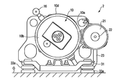
- FIG. 2 is a side view of the horizontal compressor according to the embodiment.
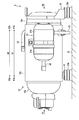
- FIG. 3 is a cross-sectional view showing the horizontal compressor according to the embodiment from the side.
- FIG. 4 is a front view of the horizontal compressor as viewed from the direction of arrow F4 in FIG.
- FIG. 5 is a rear view of the horizontal compressor as viewed from the direction of arrow F5 in FIG.
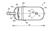
- FIG. 6 is a cross-sectional view illustrating a positional relationship among an accumulator for a compressor, a refrigerant inlet pipe, and a suction pipe according to the embodiment.
- FIG. 7 is a sectional view taken along line F7-F7 of FIG. FIG.
- FIG. 8 is a cross-sectional view showing a positional relationship between the compressor accumulator and the suction pipe according to the embodiment.
- FIG. 9 is a cross-sectional view illustrating a positional relationship among a compressor accumulator, a refrigerant inlet pipe, and a suction pipe according to a first modification of the embodiment.
- FIG. 10 is a cross-sectional view illustrating a positional relationship among an accumulator for a compressor, a refrigerant inlet pipe, and a suction pipe according to a second modification of the embodiment.
- FIG. 1 is a refrigeration cycle circuit diagram of an air conditioner 1 which is an example of a refrigeration cycle device.
- the air conditioner 1 includes a horizontal compressor 2, a four-way valve 3, an outdoor heat exchanger 4, an expansion device 5, and an indoor heat exchanger 6 as main elements.
- a plurality of elements constituting the air conditioner 1 are connected via a circulation circuit 7 through which a refrigerant circulates.
- the discharge side of the horizontal compressor 2 is connected to the first port 3 a of the four-way valve 3.
- the second port 3 b of the four-way valve 3 is connected to the outdoor heat exchanger 4.
- the outdoor heat exchanger 4 is connected to an indoor heat exchanger 6 via an expansion device 5.
- the indoor heat exchanger 6 is connected to the third port 3c of the four-way valve 3.
- the fourth port 3d of the four-way valve 3 is connected to the suction side of the horizontal compressor 2 via a compressor accumulator 21.
- the four-way valve 3 switches so that the first port 3a communicates with the second port 3b and the third port 3c communicates with the fourth port 3d.
- the high-temperature and high-pressure gas-phase refrigerant compressed by the horizontal compressor 2 is discharged to the circulation circuit 7.
- the discharged gas-phase refrigerant is guided via the four-way valve 3 to the outdoor heat exchanger 4 functioning as a radiator (condenser).
- the gas-phase refrigerant guided to the outdoor heat exchanger 4 is condensed by heat exchange with air and changes into a high-pressure liquid-phase refrigerant.
- the high-pressure liquid-phase refrigerant is reduced in pressure in the process of passing through the expansion device 5 and changes to a low-pressure gas-liquid two-phase refrigerant.
- the gas-liquid two-phase refrigerant is guided to the indoor heat exchanger 6 functioning as a heat absorber (evaporator), and exchanges heat with air while passing through the indoor heat exchanger 6.
- the gas-liquid two-phase refrigerant takes heat from the air, evaporates, and changes to a low-temperature, low-pressure gas-phase refrigerant.
- the air passing through the indoor heat exchanger 6 is cooled by the latent heat of vaporization of the liquid-phase refrigerant, becomes cool air, and is sent to a place to be air-conditioned (cooled).
- the low-temperature and low-pressure gas-phase refrigerant that has passed through the indoor heat exchanger 6 is guided to the compressor accumulator 21 via the four-way valve 3. If the liquid-phase refrigerant that has not completely evaporated is mixed in the refrigerant, it is separated here into a liquid-phase refrigerant and a gas-phase refrigerant.
- the low-temperature and low-pressure gas-phase refrigerant separated from the liquid-phase refrigerant is drawn into the horizontal compressor 2 from the compressor accumulator 21, and is again converted into a high-temperature and high-pressure gas-phase refrigerant by the horizontal compressor 2. It is compressed and discharged to the circulation circuit 7.
- the four-way valve 3 switches so that the first port 3a communicates with the third port 3c and the second port 3b communicates with the fourth port 3d.
- the high-temperature and high-pressure gas-phase refrigerant discharged from the horizontal compressor 2 is guided to the indoor heat exchanger 6 via the four-way valve 3, The heat is exchanged with the air passing through the indoor heat exchanger 6. That is, the indoor heat exchanger 6 functions as a condenser.
- the gas-phase refrigerant passing through the indoor heat exchanger 6 is condensed by exchanging heat with air, and changes into a high-pressure liquid-phase refrigerant.
- the air passing through the indoor heat exchanger 6 is heated by heat exchange with the gas-phase refrigerant and is sent to a place to be air-conditioned (heated) as hot air.
- the high-temperature liquid-phase refrigerant that has passed through the indoor heat exchanger 6 is guided to the expansion device 5, and is decompressed in the process of passing through the expansion device 5 and changes to a low-pressure gas-liquid two-phase refrigerant.
- the gas-liquid two-phase refrigerant is guided to the outdoor heat exchanger 4 functioning as an evaporator, where it is evaporated by exchanging heat with air, and changes to a low-temperature, low-pressure gas-phase refrigerant.
- the low-temperature and low-pressure gas-phase refrigerant that has passed through the outdoor heat exchanger 4 is sucked into the horizontal compressor 2 via the four-way valve 3 and the compressor accumulator 21.
- the horizontal compressor 2 is a rotary compressor that is installed in a horizontal orientation on a horizontal or nearly horizontal installation surface G, and includes a hermetic container 10, a compression mechanism 11, and a motor 12 as main elements. ing.
- the closed container 10 is supported in a horizontal position.
- the closed container 10 includes three members: a container body 10a, a first lid member 10b, and a second lid member 10c.
- the closed container 10 has a first lid member 10b shield-welded from one side X2a along the axial direction X2 to a cylindrical container body 10a having both ends opened, and a second lid Xb from the other side X2b along the axial direction X2.
- the two lid members 10c are shield-welded to maintain airtightness.
- the compression mechanism 11 and the electric motor 12 are accommodated inside the sealed container 10 in a line in the axial direction X2.
- polyalkylene glycol (PAG: polyalkylene glycol) is stored as refrigerating machine oil 40 inside closed container 10.
- the kinematic viscosity V of the polyalkylene glycol is, for example, 80 to 120 mm 2 / s at 40 ° C.
- the compression mechanism 11 is housed inside the container body 10a.
- the compression mechanism 11 is provided with a cylinder body 11a through which the crankshaft 13a of the rotating shaft 13 is inserted.
- the roller 11b is fitted on the outer peripheral surface of the crankshaft 13a.
- the cylinder body 11a has a compression chamber 11c for compressing the gas-phase refrigerant sucked from the compressor accumulator 21 via the suction pipe 23 between the cylinder body 11a and the roller 11b.
- the compression chamber 11c in which the roller 11b rotates eccentrically corresponds to the cylinder chamber 11R.
- the compression mechanism 11 has only one cylinder chamber 11R.
- the gas-phase refrigerant compressed in the compression chamber 11c is discharged into the discharge muffler 11h via the discharge valve device 15, and is discharged from the discharge muffler 11h into the closed container 10.
- the refrigerant is made of, for example, R744 which is carbon dioxide.
- the compression mechanism 11 is provided with a main bearing 11d and a sub bearing 11e that rotatably support the rotating shaft 13 so as to be arranged in the axial direction X2.
- the compression mechanism section 11 is provided with a partition member 11f that hermetically partitions a space on the compression mechanism section 11 side and a space on the electric motor section 12 side.
- the partition member 11f is an example of a partition.
- the partition member 11f is also a member that fixes the cylinder body 11a to the inner wall of the closed casing 10.
- the cylinder body 11a is fixed to the partition member 11f by a plurality of bolts 11g.
- a main bearing 11d and a sub-bearing 11e are fixed to the cylinder body 11a.
- the electric motor section 12 is an element for driving the compression mechanism section 11 and is connected to the compression mechanism section 11 via the rotating shaft 13.
- the motor unit 12 is housed inside the container body 10a at a position closer to the first lid member 10b than the compression mechanism unit 11.
- the electric motor unit 12 is, for example, a brushless DC motor.
- the motor section 12 includes a rotor 12b having a permanent magnet embedded therein and formed into a cylindrical shape, and a stator 12c surrounding the rotor 12b and having a plurality of teeth wound around a plurality of teeth.
- the rotating shaft 13 is inserted and joined to the rotor 12b.
- the rotating shaft 13 transmits the rotating motion of the electric motor unit 12 to the compression mechanism unit 11.
- the rotary shaft 13 is formed with a circular oil supply passage 13b.
- the oil supply passage 13b is a non-penetrating hole extending from the end of the compression mechanism 11 toward the electric motor 12 along the axial direction X2.
- An oil suction pipe 14 extending to the refrigerating machine oil 40 stored in the closed container 10 is connected to the oil supply passage 13 b of the rotating shaft 13.
- the oil suction pipe 14 does not follow the rotation of the rotating shaft 13.
- the rotating shaft 13 has a plurality of oil supply holes 13c penetrating from the outer peripheral surface to the oil supply passage 13b.
- the discharge pipe 16 is attached to the container body 10a.
- the discharge pipe 16 is opened inside the container body 10a at a position corresponding to the compression mechanism section 11.
- the compressor accumulator 21 is attached to the sealed container 10 in a horizontal position.
- a refrigerant inlet pipe 22 is connected to one side X1a of the compressor accumulator 21 along the axial direction X1.
- a suction pipe 23 is connected to the other side X1b of the compressor accumulator 21 along a vertical direction crossing the axial direction X1.
- the compressor accumulator 21 forms a cylindrical housing, and includes a first housing part 21a located on one side X1a and a second housing located on the other side X1b.
- the portion 21b is shield-welded along the axial direction X1.
- the first housing portion 21a has a first opening 21c in a direction facing the other side X1b.
- the first housing portion 21a has a first connection hole 21e formed at an end on one side X1a.
- the first connection hole 21e is a through hole formed by burring from one side X1a to the other side X1b of the first housing portion 21a, and has a rising portion 21e1 inside the first housing portion 21a. I have.
- a filter 21f is provided inside the first housing 21a so as to face the first connection hole 21e.
- the second housing portion 21b has a second opening 21d in a direction facing one side X1a.
- the second housing portion 21b has a second connection hole 21g formed below the other side X1b.
- the second connection hole 21g is a through-hole that is burred upward from below the other side X1b of the second housing portion 21b, and has a rising portion 21g1 inside the second housing portion 21b. I have.
- the refrigerant inlet pipe 22 is inserted into the first connection hole 21e of the first housing portion 21a along the axial direction X1 of the accumulator 21 for the compressor, and connected by brazing. I have.
- the refrigerant inlet pipe 22 is located on one side X1a in the axial direction X1 of the compressor accumulator 21, and sucks the refrigerant including the refrigerating machine oil 40 circulated from the circulation circuit 7 into the compressor accumulator 21.
- the suction pipe 23 is inserted into the second connection hole 21g of the second housing portion 21b along the vertical direction and connected by brazing.
- the suction pipe 23 is located on the other side X1b in the axial direction X1 of the compressor accumulator 21, and returns the refrigerant from which the refrigerating machine oil 40 has been separated from the compressor accumulator 21 to the closed container 10.
- the suction pipe 23 is connected to a position Xd farther from the first housing portion 21a than a center position Xc of the entire length La along the axial direction X1 of the second housing portion 21b. .
- the suction pipe 23 is formed with an oil return hole 23 a that returns a part of the refrigerating machine oil 40 separated from the refrigerant inside the compressor accumulator 21 to the closed container 10. .
- the oil return hole 23a is opened so that at least a part thereof faces the opening direction of the refrigerant inlet pipe 22.
- the oil return hole 23a opens from the one side X1a of the compressor accumulator 21 to the other side X1b with respect to the suction pipe 23.
- the oil return hole 23a is formed in a range of, for example, ⁇ 45 ° with respect to the suction pipe 23 with respect to the opening direction of the refrigerant inlet pipe 22.
- the oil return hole 23a formed in the suction pipe 23 is closed. At least some can be recognized. In other words, at least a part of the oil return hole 23a is opened toward the refrigerant inlet pipe 22.
- the first leg 31 and the second leg 32 support the closed container 10 on the installation surface G in a horizontal position via support members 33a and 33b, respectively.
- the first leg 31 is an integrally molded product obtained by subjecting a metal plate material such as a cold-rolled steel plate or a hot-rolled steel plate to sheet metal press working, and is provided on one side of the sealed container 10 corresponding to the electric motor unit 12.
- X2a The second leg 32 is an integrally molded product obtained by subjecting a metal plate such as a cold-rolled steel plate or a hot-rolled steel plate to a sheet metal press process, and is the other end of the sealed container 10 corresponding to the compression mechanism unit 11. It is fixed to the side X2b.
- the support member 33a is provided between the first leg 31 and the installation surface G. As shown in FIGS. 3 and 4, the support member 33a is provided at both ends of the first leg 31 orthogonal to the axial direction X2 on a horizontal plane at a position on one side X2a along the axial direction X2 than the electric motor unit 12. It is provided and supports the closed container 10 on the installation surface G via the first leg 31. As shown in FIGS. 3 and 5, the support member 33b is provided at both ends of the second leg 32 orthogonal to the axial direction X2 on a horizontal plane at a position on the other side X2b along the axial direction X2 than the cylinder chamber 11R. It is provided and supports the closed container 10 on the installation surface G via the second leg 32. Therefore, the support members 33a and 33b are arranged at the four corners of the closed container 10.
- the support members 33a and 33b of the present embodiment are made of, for example, butyl rubber.
- the spring constant of the support members 33a and 33b is, for example, 15 to 35 N / mm at a normal temperature of 20 ° C.
- the spring constant of each of the support members 33a and 33b located at the four corners of the closed container 10 may be the same or different as long as it is within the range of 15 to 35 N / mm at 20 ° C.
- the refrigerant inlet pipe 22 is connected to one side X1a of the accumulator 21 for the compressor in the axial direction X1.
- the suction pipe 23 is connected to the other side X1b in the axial direction X1 of the compressor accumulator 21 along a direction crossing the axial direction X1.
- the oil return hole 23 a formed in the suction pipe 23 is opened so that at least a part thereof faces the opening direction of the refrigerant inlet pipe 22.
- the oil return hole 23a formed in the suction pipe 23 is located so as to face the refrigerant inlet pipe 22. Therefore, the refrigerating machine oil 40 contained in the refrigerant sucked from the refrigerant inlet pipe 22 easily flows into the suction pipe 23 from the oil return hole 23a.
- the horizontal compressor 2 and the air conditioner 1 including the horizontal compressor 2 allow the refrigerating machine oil 40 separated from the refrigerant by the compressor accumulator 21 to pass through the suction pipe 23 to the closed container 10. Can be easily returned.
- the compressor accumulator 21 is formed by joining the first housing 21a to which the refrigerant inlet pipe 22 is connected and the second housing 21b to which the suction pipe 23 is connected.
- the suction pipe 23 is connected to a position Xd farther from the first housing portion 21a than a center position Xc of the entire length La along the axial direction X1 of the second housing portion 21b.
- the suction pipe 23 can be sufficiently separated from the refrigerant inlet pipe 22. Further, by connecting the suction pipe 23 to the position Xd, the space on the side opposite to the suction pipe 23 in the second housing portion 21b can be made sufficiently small. Thereby, the refrigerating machine oil 40 separated from the refrigerant by the compressor accumulator 21 can be prevented from wrapping around the suction pipe 23 and accumulating at the bottom. As a result, the refrigerator oil 40 can be efficiently returned to the closed container 10.
- the suction pipe 23 can be sufficiently separated from the refrigerant inlet pipe 22 in the compressor accumulator 21, the gas-liquid separation performance can be sufficiently ensured.
- the accumulator 21 for the compressor by configuring the accumulator 21 for the compressor with two pieces of the first housing part 21a and the second housing part 21b, it is possible to increase the degree of freedom in design as compared with the case where the accumulator 21 is formed with three pieces. it can.
- the reason for this is that the suction pipe 23 cannot be provided at the welded portion between the divided housing portions.
- the refrigerant comprises R744, which is carbon dioxide.
- the refrigerating machine oil 40 is made of polyalkylene glycol.
- the kinematic viscosity V of the polyalkylene glycol is 80 to 120 mm 2 / s at 40 ° C.
- the operating pressure can be increased and the torque of the motor can be increased as compared with other materials.
- the refrigerant made of R744 tends to have a higher temperature than the refrigerant made of other materials. Therefore, a polyalkylene glycol whose kinematic viscosity fluctuates less with a temperature change than a refrigerating machine oil made of another material is used.
- the accumulator 21 for the compressor has a lower temperature and a lower pressure than the closed container 10.
- the polyalkylene glycol tends to have low fluidity inside the accumulator 21 for the compressor
- the polyalkylene glycol is defined by defining the opening direction of the oil return hole 23a provided in the suction pipe 23 as described above. Glycol can be easily returned to the closed container 10 from the oil return hole 23a.
- the refrigerant made of another material is, for example, R404A.
- the refrigerating machine oil made of another material is, for example, polyvinyl ether (PVE) or polyol ester (POE).
- the compression mechanism 11 has a single cylinder chamber 11R.
- the support member 33a supports the closed container 10 on the installation surface G at a position on one side X2a along the axial direction X2 of the closed container 10 with respect to the electric motor unit 12.
- the support member 33b supports the closed container 10 on the installation surface G at a position on the other side X2b along the axial direction X2 of the closed container 10 with respect to the cylinder chamber 11R of the compression mechanism unit 11.
- the spring constant of the support members 33a and 33b is 15 to 35 N / mm at 20 ° C.
- the compression mechanism unit 11 having the single cylinder chamber 11R has a larger vibration during operation as compared with the compression mechanism unit having a plurality of cylinder chambers as a comparative example, but the vibration caused by the support members 33a and 33b. Can be sufficiently absorbed, and propagation of vibration to the installation surface G can be suppressed. As a result, noise can be sufficiently suppressed by the support members 33a and 33b.
- the support member 33a is provided at a position on one side X2a along the axial direction X2 with respect to the electric motor unit 12, deterioration due to heat generated from the electric motor unit 12 can be suppressed.
- the support member 33b is provided at a position on the other side X2b along the axial direction X2 with respect to the cylinder chamber 11R, it is possible to suppress deterioration due to heat generated from refrigerant compressed and discharged in the cylinder chamber 11R. Can be. In particular, when R744, which becomes high in temperature, is used as the refrigerant, the deterioration of the support member 33b due to heat can be effectively suppressed.
- the support members 33a and 33b can absorb and radiate the heat transmitted from the sealed container 10 to a certain extent, it is possible to suppress the transmission of heat to the installation surface G side. This is particularly effective when R744, which becomes high in temperature, is used as the refrigerant.
- the support members 33a and 33b are fixed to the closed container 10 via the first leg 31 and the second leg 32 whose surface area is increased as a shape bent so as to be folded, heat is easily radiated. In addition, deterioration due to heat can be suppressed.
- the first housing 21 a and the second housing 21 b constituting the compressor accumulator 21 are prepared.
- the suction pipe 23 is moved in the direction intersecting the axial direction X1 with the second connection hole 21g of the second housing part 21b so that the oil return hole 23a formed in the suction pipe 23 faces the first housing part 21a. Connect by brazing along.
- the suction pipe 23 is brazed to the second connection hole 21g of the second housing portion 21b, it can be easily confirmed whether or not the oil return hole 23a is closed by the wax.
- the wax can easily approach the oil return hole 23a of the suction pipe 23 along the rising portion 21g1 of the second connection hole 21g, but can be sufficiently inspected. As a result, it is possible to prevent shipment of a defective product in which the oil return hole 23a is closed by the wax.
- the identification may be based on visual recognition of an operator, or may be based on image recognition using, for example, a CCD camera.
- the horizontal compressor 2 may be installed inclined.
- the compressor accumulator 21 is relatively lower on the motor unit 12 side with respect to the axial direction X1 of the compressor accumulator 21 and relatively on the compression mechanism unit 11 side. It is provided to be inclined so as to be as high as possible. In other words, one side X1a of the compressor accumulator 21 is lower than the other side X1b.
- the compressor accumulator 21 is relatively lower on the compression mechanism unit 11 side with respect to the axial direction X1 of the compressor accumulator 21, and relatively on the electric motor unit 12 side. It is provided to be inclined so as to be higher. In other words, the other side X1b of the compressor accumulator 21 is lower than the one side X1a.
- one of the two oil return holes 23a is located lower than the other inside the compressor accumulator 21 regardless of the inclination in any direction. Therefore, the refrigerating machine oil 40 separated from the refrigerant can be returned to the closed container 10 from one of the lower oil return holes 23a.
Landscapes
- Engineering & Computer Science (AREA)
- Mechanical Engineering (AREA)
- General Engineering & Computer Science (AREA)
- Physics & Mathematics (AREA)
- Thermal Sciences (AREA)
- Chemical & Material Sciences (AREA)
- Analytical Chemistry (AREA)
- Power Engineering (AREA)
- Applications Or Details Of Rotary Compressors (AREA)
- Compressor (AREA)
Abstract
本発明の目的は、冷媒から分離された冷凍機油を密閉容器に戻し易い横置き形圧縮機を得ることにある。 圧縮機用アキュムレータは(21)、圧縮機用アキュムレータ(21)の軸方向X1の一方側(X1a)に接続され冷凍機油を含む冷媒を圧縮機用アキュムレータ(21)に吸い込む冷媒入口管(22)、圧縮機用アキュムレータ (21)の軸方向(X1)の他方側(X1b)に軸方向(X1)と交差する方向に沿って接続され冷凍機油が分離された冷媒を圧縮機に戻す吸込み管(23)を具備している。吸込み管(23)には、圧縮機用アキュムレータ(21)内の冷媒から分離された冷凍機油を圧縮機に戻す油戻し穴()23aが形成されている。油戻し穴(23a)は、少なくとも一部が冷媒入口管(22)の開口方向に臨むように開口されている。
Description
本発明の実施形態は、圧縮機用アキュムレータ、圧縮機用アキュムレータの製造方法、横置き形圧縮機および当該横置き形圧縮機を有する冷凍サイクル装置に関する。
横置き形圧縮機は、筒状の密閉容器と、密閉容器の内部に収容され冷媒を圧縮する圧縮機構部と、密閉容器の内部に収容され回転軸を介して圧縮機構部を駆動する電動機部と、を具備している。また、横置き形圧縮機は、圧縮機用アキュムレータと、冷媒を圧縮機用アキュムレータに吸い込む冷媒入口管と、圧縮機用アキュムレータによって油が分離された冷媒を密閉容器に戻す吸込み管と、を具備している。
吸込み管には、圧縮機用アキュムレータの内部において冷媒から分離された冷凍機油を密閉容器に戻す油戻し穴が形成されている。
冷媒は、密閉容器に戻される前に、圧縮機用アキュムレータによって冷凍機油が分離される。冷凍機油が分離された冷媒は、吸込み管を介して密閉容器に戻される。ここで、冷媒から分離された冷凍機油は、油戻し穴を介して密閉容器に戻される。従来は、冷凍機油が油戻し穴から密閉容器に戻り難い虞があった。
本発明の目的は、冷媒から分離された冷凍機油を密閉容器に戻し易い横置き形圧縮機を得ることにある。
実施形態によれば、圧縮機用アキュムレータは、横置きの姿勢で配置される筒状の筐体と、前記筐体の軸方向の一方側に接続され、冷媒を前記筐体内に吸い込む冷媒入口管と、
前記筐体の軸方向の他方側に前記軸方向と交差する方向に沿って接続され、前記冷媒を圧縮機に導く吸込み管と、を具備し、前記吸込み管には、前記筐体の内部において前記冷媒から分離された冷凍機油を圧縮機に戻す油戻し穴が形成され、前記油戻し穴は、少なくとも一部が前記冷媒入口管の開口方向に臨むように開口されている。
前記筐体の軸方向の他方側に前記軸方向と交差する方向に沿って接続され、前記冷媒を圧縮機に導く吸込み管と、を具備し、前記吸込み管には、前記筐体の内部において前記冷媒から分離された冷凍機油を圧縮機に戻す油戻し穴が形成され、前記油戻し穴は、少なくとも一部が前記冷媒入口管の開口方向に臨むように開口されている。
[実施形態]
以下、実施形態について図1ないし図8を参照して説明する。
以下、実施形態について図1ないし図8を参照して説明する。
図1は、例えば冷凍サイクル装置の一例である空気調和機1の冷凍サイクル回路図である。空気調和機1は、横置き形圧縮機2、四方弁3、室外熱交換器4、膨張装置5および室内熱交換器6を主要な要素として備えている。空気調和機1を構成する複数の要素は、冷媒が循環する循環回路7を介して接続されている。
具体的に述べると、図1に示すように、横置き形圧縮機2の吐出側は、四方弁3の第1ポート3aに接続されている。四方弁3の第2ポート3bは、室外熱交換器4に接続されている。室外熱交換器4は、膨張装置5を介して室内熱交換器6に接続されている。室内熱交換器6は、四方弁3の第3ポート3cに接続されている。四方弁3の第4ポート3dは、圧縮機用アキュムレータ21を介して横置き形圧縮機2の吸入側に接続されている。
空気調和機1が冷房モードで運転を行う場合、四方弁3は、第1ポート3aが第2ポート3bに連通し、第3ポート3cが第4ポート3dに連通するように切り替わる。冷房モードで空気調和機1の運転が開始されると、横置き形圧縮機2で圧縮された高温・高圧の気相冷媒が循環回路7に吐出される。吐出された気相冷媒は、四方弁3を経由して放熱器(凝縮器)として機能する室外熱交換器4に導かれる。
室外熱交換器4に導かれた気相冷媒は、空気との熱交換により凝縮し、高圧の液相冷媒に変化する。高圧の液相冷媒は、膨張装置5を通過する過程で減圧されて低圧の気液二相冷媒に変化する。気液二相冷媒は、吸熱器(蒸発器)として機能する室内熱交換器6に導かれるとともに、室内熱交換器6を通過する過程で空気と熱交換する。
この結果、気液二相冷媒は、空気から熱を奪って蒸発し、低温・低圧の気相冷媒に変化する。室内熱交換器6を通過する空気は、液相冷媒の蒸発潜熱により冷やされ、冷風となって空調(冷房)すべき場所に送られる。
室内熱交換器6を通過した低温・低圧の気相冷媒は、四方弁3を経由して圧縮機用アキュムレータ21に導かれる。冷媒中に蒸発しきれなかった液相冷媒が混入している場合は、ここで液相冷媒と気相冷媒とに分離される。液相冷媒から分離された低温・低圧の気相冷媒は、圧縮機用アキュムレータ21から横置き形圧縮機2に吸い込まれるとともに、当該横置き形圧縮機2で再び高温・高圧の気相冷媒に圧縮されて循環回路7に吐出される。
一方、空気調和機1が暖房モードで運転を行う場合、四方弁3は、第1ポート3aが第3ポート3cに連通し、第2ポート3bが第4ポート3dに連通するように切り替わる。暖房モードで空気調和機1の運転が開始されると、横置き形圧縮機2から吐出された高温・高圧の気相冷媒は、四方弁3を経由して室内熱交換器6に導かれ、当該室内熱交換器6を通過する空気と熱交換される。すなわち、室内熱交換器6が凝縮器として機能する。
この結果、室内熱交換器6を通過する気相冷媒は、空気と熱交換することにより凝縮し、高圧の液相冷媒に変化する。室内熱交換器6を通過する空気は、気相冷媒との熱交換により加熱され、温風となって空調(暖房)すべき場所に送られる。
室内熱交換器6を通過した高温の液相冷媒は、膨張装置5に導かれるとともに、当該膨張装置5を通過する過程で減圧されて低圧の気液二相冷媒に変化する。気液二相冷媒は、蒸発器として機能する室外熱交換器4に導かれるとともに、ここで空気と熱交換することにより蒸発し、低温・低圧の気相冷媒に変化する。室外熱交換器4を通過した低温・低圧の気相冷媒は、四方弁3および圧縮機用アキュムレータ21を経由して横置き形圧縮機2に吸い込まれる。
次に、空気調和機1に用いられる横置き形圧縮機2の具体的な構成について、図2ないし図8を参照して説明する。横置き形圧縮機2は、水平もしくは水平に近い設置面Gの上に横置きの姿勢で据え付けられるロータリーコンプレッサであって、密閉容器10、圧縮機構部11および電動機部12を主要な要素として備えている。
図2および図3に示すように、密閉容器10は、横置きの姿勢で支持されている。密閉容器10は、容器本体10a、第1蓋部材10bおよび第2蓋部材10cの3つの部材から構成されている。密閉容器10は、両端が開口した円筒形状の容器本体10aに対して、軸方向X2に沿う一方側X2aから第1蓋部材10bがシールド溶接され、かつ、軸方向X2に沿う他方側X2bから第2蓋部材10cがシールド溶接されて、気密性が保たれている。密閉容器10の内部には、圧縮機構部11と電動機部12とが軸方向X2に並んで収容されている。
図3に示すように、密閉容器10の内部には、冷凍機油40としてポリアルキレングリコール(PAG:polyalkylene glycol)が貯留されている。ポリアルキレングリコールの動粘度Vは、例えば40℃において80ないし120mm2/sである。
図3に示すように、圧縮機構部11は、容器本体10aの内部に収容されている。圧縮機構部11には、回転軸13のクランク軸部13aを挿通させたシリンダボディ11aが設けられている。ローラ11bが、クランク軸部13aの外周面に嵌合されている。シリンダボディ11aは、ローラ11bとの間に、吸込み管23を介して圧縮機用アキュムレータ21から吸い込んだ気相冷媒を圧縮する圧縮室11cを有している。シリンダボディ11aにおいて、ローラ11bが偏心して回転する圧縮室11cは、シリンダ室11Rに相当する。圧縮機構部11は、シリンダ室11Rを1つだけ設けている。圧縮室11cで圧縮された気相冷媒は、吐出弁装置15を介して吐出マフラ11h内に吐出され、吐出マフラ11hから密閉容器10の内部に吐出される。冷媒は、例えば二酸化炭素であるR744からなる。
圧縮機構部11には、回転軸13を回転自在に支持する主軸受け11dと副軸受け11eとが軸方向X2に並ぶように設けられている。圧縮機構部11には、圧縮機構部11側の空間と、電動機部12側の空間とを気密に仕切る仕切部材11fが設けられている。仕切部材11fは、仕切部の一例である。仕切部材11fは、シリンダボディ11aを密閉容器10の内壁に固定する部材でもある。仕切部材11fには、複数のボルト11gによって、シリンダボディ11aが固定されている。また、シリンダボディ11aには、主軸受け11dと副軸受け11eとが固定されている。
図3に示すように、電動機部12は、圧縮機構部11を駆動する要素であって、回転軸13を介して圧縮機構部11に連結されている。電動機部12は、圧縮機構部11よりも第1蓋部材10bの側に偏った位置で容器本体10aの内部に収容されている。電動機部12は、例えばブラシレスDCモータである。電動機部12は、永久磁石を埋設し円筒形状に形成された回転子12bと、回転子12bを囲み複数のティースに巻線が巻回された固定子12cとを有している。回転子12bには、回転軸13が挿入されて接合されている。
図3に示すように、回転軸13は、電動機部12の回転運動を圧縮機構部11に伝達する。回転軸13には、円形状の給油通路13bが形成されている。給油通路13bは、圧縮機構部11の端部側から軸方向X2に沿って電動機部12側に伸びた非貫通の穴からなる。回転軸13の給油通路13bには、密閉容器10に貯留された冷凍機油40まで伸びた油吸い込み管14が連結されている。油吸い込み管14は、回転軸13の回転に従動しない。図3に示すように、回転軸13には、外周面から給油通路13bに貫通する複数の給油穴13cが形成されている。
図2ないし図4に示すように、吐出管16は、容器本体10aに取り付けられている。吐出管16は、圧縮機構部11に対応した位置で容器本体10aの内部に開口されている。
図2に示すように、圧縮機用アキュムレータ21は、横置きの姿勢で密閉容器10に付設されている。図2、図6および図7に示すように、圧縮機用アキュムレータ21の一方側X1aには、冷媒入口管22が軸方向X1に沿って接続されている。圧縮機用アキュムレータ21の他方側X1bには、吸込み管23が軸方向X1と交差した垂直方向に沿って接続されている。図6および図7に示すように、圧縮機用アキュムレータ21は、筒状の筐体を構成し、一方側X1aに位置する第1筐体部21aと、他方側X1bに位置する第2筐体部21bとが、軸方向X1に沿ってシールド溶接されて構成されている。
図6および図7に示すように、第1筐体部21aは、他方側X1bに臨む方向に第1開口21cを備えている。第1筐体部21aには、一方側X1aの端部に第1接続穴21eが形成されている。第1接続穴21eは、第1筐体部21aの一方側X1aから他方側X1bに向かってバーリング加工された貫通穴であって、第1筐体部21aの内部に立ち上がり部位21e1を有している。第1筐体部21aの内部には、第1接続穴21eに対向するようにフィルター21fが設けられている。
図6および図7に示すように、第2筐体部21bは、一方側X1aに臨む方向に第2開口21dを備えている。第2筐体部21bには、他方側X1bの下部に第2接続穴21gが形成されている。第2接続穴21gは、第2筐体部21bの他方側X1bの下方から上方に向かってバーリング加工された貫通穴であって、第2筐体部21bの内部に立ち上がり部位21g1を有している。
図6および図7に示すように、冷媒入口管22は、第1筐体部21aの第1接続穴21eに圧縮機用アキュムレータ21の軸方向X1に沿って挿入され、ろう付けによって接続されている。冷媒入口管22は、圧縮機用アキュムレータ21の軸方向X1の一方側X1aに位置するとともに、循環回路7から循環された冷凍機油40を含む冷媒を圧縮機用アキュムレータ21に吸い込む。
図6および図7に示すように、吸込み管23は、第2筐体部21bの第2接続穴21gに垂直方向に沿って挿入され、ろう付けによって接続されている。吸込み管23は、圧縮機用アキュムレータ21の軸方向X1の他方側X1bに位置するとともに、冷凍機油40が分離された冷媒を圧縮機用アキュムレータ21から密閉容器10に戻す。図6に示すように、吸込み管23は、第2筐体部21bの軸方向X1に沿った全長Laの中心位置Xcよりも、第1筐体部21aから離れた位置Xdに接続されている。
図6ないし図8に示すように、吸込み管23には、圧縮機用アキュムレータ21の内部において冷媒から分離された冷凍機油40の一部を密閉容器10に戻す油戻し穴23aが形成されている。油戻し穴23aは、少なくとも一部が冷媒入口管22の開口方向に臨むように開口されている。言い換えると、油戻し穴23aは、吸込み管23に対して、圧縮機用アキュムレータ21の一方側X1aから他方側X1bに向かって開口している。具体的には、油戻し穴23aは、吸込み管23に対して、冷媒入口管22の開口方向を基準として例えば±45°の範囲に形成されている。このため、圧縮機用アキュムレータ21の一方側X1aから他方側X1bに向かって、第2開口21dから第2筐体部21bの内部を視認した場合、吸込み管23に形成された油戻し穴23aの少なくとも一部が認識できる。言い換えると、油戻し穴23aの少なくとも一部が、冷媒入口管22に向かって開口されている。
図2ないし図5に示すように、第1の脚31および第2の脚32は、夫々支持部材33aおよび33bを介して、密閉容器10を設置面Gの上に横置きの姿勢で支持している。第1の脚31は、例えば冷間圧延鋼板あるいは熱間圧延鋼板のような金属製の板材に板金プレス加工を施した一体成型品であって、電動機部12に対応した密閉容器10の一方側X2aに固定されている。第2の脚32は、例えば冷間圧延鋼板あるいは熱間圧延鋼板のような金属製の板材に板金プレス加工を施した一体成型品であって、圧縮機構部11に対応した密閉容器10の他方側X2bに固定されている。
図4に示すように、支持部材33aは、第1の脚31と設置面Gとの間に設けられている。図3および図4に示すように、支持部材33aは、電動機部12よりも軸方向X2に沿った一方側X2aの位置において、軸方向X2と水平面上において直交する第1の脚31の両端に設けられ、第1の脚31を介して密閉容器10を設置面Gの上に支持する。図3および図5に示すように、支持部材33bは、シリンダ室11Rよりも軸方向X2に沿った他方側X2bの位置において、軸方向X2と水平面上において直交する第2の脚32の両端に設けられ、第2の脚32を介して密閉容器10を設置面Gの上に支持する。したがって、支持部材33aおよび33bは、密閉容器10の四隅に配置されている。
本実施形態の支持部材33aおよび33bは、例えばブチルゴムからなる。支持部材33aおよび33bのばね定数は、常温である20℃において、例えば15ないし35N/mmである。密閉容器10の四隅に位置する各々の支持部材33aおよび33bのばね定数は、20℃において15ないし35N/mmの範囲内であれば、同一としてもよいし、異ならせてもよい。
本実施形態によると、冷媒入口管22は、圧縮機用アキュムレータ21の軸方向X1の一方側X1aに接続されている。吸込み管23は、圧縮機用アキュムレータ21の軸方向X1の他方側X1bに軸方向X1と交差する方向に沿って接続されている。吸込み管23に形成されている油戻し穴23aは、少なくとも一部が冷媒入口管22の開口方向に臨むように開口されている。
このため、吸込み管23に形成された油戻し穴23aは、冷媒入口管22に対面するように位置する。したがって、冷媒入口管22から吸い込まれた冷媒に含まれる冷凍機油40は、油戻し穴23aから吸込み管23に流入し易い。この結果、横置き形圧縮機2および横置き形圧縮機2を備えた空気調和機1は、圧縮機用アキュムレータ21で冷媒から分離された冷凍機油40を、吸込み管23を介して密閉容器10に戻し易くすることができる。
本実施形態によると、圧縮機用アキュムレータ21は、冷媒入口管22が接続された第1筐体部21aと、吸込み管23が接続された第2筐体部21bとが、接合されてなる。吸込み管23は、第2筐体部21bの軸方向X1に沿った全長Laの中心位置Xcよりも、第1筐体部21aから離れた位置Xdに接続されている。
このため、圧縮機用アキュムレータ21において、吸込み管23を冷媒入口管22から十分に離間させることができる。また、吸込み管23を位置Xdに接続したことで、第2筐体部21bにおける吸込み管23と反対側の空間を十分に小さくすることができる。これにより、圧縮機用アキュムレータ21で冷媒から分離された冷凍機油40が、吸込み管23の後方に回り込み底部に溜まることを抑制できる。この結果、密閉容器10に対して冷凍機油40を効率よく戻すことができる。
また、圧縮機用アキュムレータ21において、吸込み管23を冷媒入口管22から十分に離間させることができることから、気液分離性能を十分に確保することができる。
また、吸込み管23を接続する第2接続穴21gを、第2筐体部21bの第2開口21dから十分に離間させることによって、リークなどの不具合を抑制することができる。特に、冷媒に、高圧になる二酸化炭素を用いる場合に好ましい。
また、圧縮機用アキュムレータ21を、第1筐体部21aと第2筐体部21bの2ピースで構成することによって、3ピースで構成する場合と比較して、設計の自由度を高めることができる。この理由は、分割された筐体部と筐体部との溶接部分には、吸込み管23を設けることができないからである。
本実施形態によると、冷媒は、二酸化炭素であるR744からなる。冷凍機油40は、ポリアルキレングリコールからなる。ポリアルキレングリコールの動粘度Vは、40℃において80ないし120mm2/sである。
このため、冷媒にR744を用いることで、他の材質と比較して、動作圧力を高めて、モータのトルクを大きくすることができる。しかしながら、R744からなる冷媒は、他の材質からなる冷媒と比較して、高温になり易い。そこで、他の材質からなる冷凍機油と比較して、温度変化に伴う動粘度の変動が小さいポリアルキレングリコールを用いている。一方、圧縮機用アキュムレータ21は、密閉容器10と比較して、低温かつ低圧である。この結果、圧縮機用アキュムレータ21の内部においてポリアルキレングリコールは、流動性が低くなり易いが、吸込み管23に設けられた油戻し穴23aの開口方向を前述のように規定することで、ポリアルキレングリコールを油戻し穴23aから密閉容器10に戻し易くすることができる。
なお、他の材質からなる冷媒とは、例えば、R404Aである。また、他の材質からなる冷凍機油とは、例えば、ポリビニールエーテル(PVE:polyvinyl ether)やポリオールエステル(POE:polyol ester)である。
本実施形態によると、圧縮機構部11は、単一のシリンダ室11Rを有している。支持部材33aは、電動機部12よりも密閉容器10の軸方向X2に沿った一方側X2aの位置で、密閉容器10を設置面Gの上に支持している。支持部材33bは、圧縮機構部11のシリンダ室11Rよりも密閉容器10の軸方向X2に沿った他方側X2bの位置で、密閉容器10を設置面Gの上に支持している。支持部材33aおよび33bのばね定数は、20℃において15ないし35N/mmである。
このため、単一のシリンダ室11Rを有する圧縮機構部11は、対比例として複数のシリンダ室を有する圧縮機構部と比較して、運転中の振動が大きくなるが、支持部材33aおよび33bによって振動を十分に吸収して、設置面Gに振動が伝播することを抑制できる。この結果、支持部材33aおよび33bによって、騒音を十分に抑制することができる。
また、支持部材33aは、電動機部12よりも軸方向X2に沿った一方側X2aの位置に設けていることから、電動機部12から発生する熱による劣化を抑制することができる。また、支持部材33bは、シリンダ室11Rよりも軸方向X2に沿った他方側X2bの位置に設けていることから、シリンダ室11Rにおいて圧縮および吐出される冷媒から発生する熱による劣化を抑制することができる。特に、冷媒に高温になるR744を用いている場合に、支持部材33bの熱による劣化を効果的に抑制することができる。
また、支持部材33aおよび33bは密閉容器10から伝播される熱を一定程度、吸収して放熱できることから、設置面G側への熱の伝播を抑制することができる。特に、冷媒に高温になるR744を用いている場合に効果的である。
また、支持部材33aおよび33bは、折り返すように屈折させた形状として表面積を増加させた第1の脚31および第2の脚32を介して密閉容器10に固定されていることから、放熱し易く、熱による劣化を抑制することができる。
ここで、対比例として、ばね定数が20℃において35N/mmを超える支持部材を用いた場合、横置き形圧縮機の振動を吸収することが難しく、騒音が過大となる。また、対比例として、ばね定数が20℃において10N/mmに満たない支持部材を用いた場合、横置き形圧縮機の自重によって支持部材が変形して沈み込み、横置き形圧縮機の姿勢を保つことが難しくなる。
本実施形態によると、横置き形圧縮機2の製造方法では、圧縮機用アキュムレータ21を構成する第1筐体部21aと、第2筐体部21bとを準備する。吸込み管23に形成された油戻し穴23aが第1筐体部21aの側に臨むように、吸込み管23を第2筐体部21bの第2接続穴21gに軸方向X1と交差する方向に沿ってろう付けによって接続する。第1筐体部21aと第2筐体部21bとを軸方向X1に沿って接続する前に、吸込み管23に形成された油戻し穴23aが、ろう付けによって閉塞されているか否かを、軸方向X1に沿って第2筐体部21bの開口から識別する。
このため、吸込み管23を第2筐体部21bの第2接続穴21gに対してろう付けしたときに、油戻し穴23aがろうによって閉塞されていないかを容易に確認することができる。ろうは、第2接続穴21gの立ち上がり部位21g1に沿って、吸込み管23の油戻し穴23aに接近し易いが、十分に検査することができる。この結果、ろうによって油戻し穴23aが閉塞した不良品の出荷を防止することができる。識別は、作業員の目視による認識に基づくものであってもよいし、例えばCCDカメラによる画像認識に基づくものであってもよい。
[実施形態の変形例]
以下、実施形態の変形例について図9および図10を参照して説明する。
以下、実施形態の変形例について図9および図10を参照して説明する。
本変形例は、油戻し穴23aを180°異なる位置に2つ設けたものである。横置き形圧縮機2は、傾斜されて設置される可能性がある。例えば、図9に示すように、実施形態の変形例1では、圧縮機用アキュムレータ21が、圧縮機用アキュムレータ21の軸方向X1に対して電動機部12側が相対的に低く圧縮機構部11側が相対的に高くなるように、傾斜されて設けられている。言い換えると、圧縮機用アキュムレータ21の一方側X1aが、他方側X1bよりも低くされている。
図10に示すように、実施形態の変形例2では、圧縮機用アキュムレータ21が、圧縮機用アキュムレータ21の軸方向X1に対して圧縮機構部11側が相対的に低く電動機部12側が相対的に高くなるように、傾斜されて設けられている。言い換えると、圧縮機用アキュムレータ21の他方側X1b、一方側X1aよりも低くされている。
本実施形態の変形例によると、いずれの方向に傾斜した場合でも、圧縮機用アキュムレータ21の内部において、2つの油戻し穴23aの一方が他方よりも低い位置になる。そのため、位置の低い一方の油戻し穴23aから、冷媒から分離された冷凍機油40を密閉容器10に戻すことができる。
本発明のいくつかの実施形態を説明したが、これらの実施形態は、例として提示したものであり、発明の範囲を限定することは意図していない。これら新規な実施形態は、その他の様々な形態で実施されることが可能であり、発明の要旨を逸脱しない範囲で、種々の省略、置き換え、変更を行うことができる。これら実施形態やその変形は、発明の範囲や要旨に含まれるとともに、特許請求の範囲に記載された発明とその均等の範囲に含まれる。
1…冷凍サイクル装置(空気調和機)、2…横置き形圧縮機、4…放熱器(室外熱交換器)、5…膨張装置、6…吸熱器(室内熱交換器)、7…循環回路、10…密閉容器、11…圧縮機構部、12…電動機部、21…圧縮機用アキュムレータ、21a 第1筐体部、21b 第2筐体部、22…冷媒入口管、23…吸込み管、23a…油戻し穴、40…冷凍機油、X1…圧縮機用アキュムレータ21の軸方向、X1a…圧縮機用アキュムレータ21の軸方向X1の一方側、X1b…圧縮機用アキュムレータ21の軸方向X1の他方側。
Claims (10)
- 横置きの姿勢で配置される筒状の筐体と、
前記筐体の軸方向の一方側に接続され、冷媒を前記筐体内に吸い込む冷媒入口管と、
前記筐体の軸方向の他方側に前記軸方向と交差する方向に沿って接続され、前記冷媒を圧縮機に導く吸込み管と、を具備し、
前記吸込み管には、前記筐体の内部において前記冷媒から分離された冷凍機油を圧縮機に戻す油戻し穴が形成され、
前記油戻し穴は、少なくとも一部が前記冷媒入口管の開口方向に臨むように開口された圧縮機用アキュムレータ。 - 前記圧縮機用アキュムレータは、前記冷媒入口管が接続され前記他方側に第1開口を備えた第1筐体部と、前記吸込み管が接続され前記一方側に第2開口を備えた第2筐体部と、が前記圧縮機用アキュムレータの前記軸方向に沿って接合されてなり、
前記吸込み管は、前記第2筐体部の前記軸方向に沿った全長の中心位置よりも、前記第1筐体部から離れた位置に接続された請求項1に記載の圧縮機用アキュムレータ。 - 横置きの姿勢で配置された筒状の密閉容器と、
前記密閉容器の内部で前記冷媒を圧縮する圧縮機構部と、
横置きの姿勢で前記密閉容器に付設された請求項1に記載の圧縮機用アキュムレータと、
を具備した横置き形圧縮機。 - 前記冷媒は、R744からなり、
前記冷凍機油は、ポリアルキレングリコールからなり、
前記ポリアルキレングリコールの動粘度は、40℃において80ないし120mm2/sである請求項3に記載の横置き形圧縮機。 - 前記圧縮機構部に対し前記密閉容器の前記軸方向に並ぶように前記密閉容器の内部に収容され、前記圧縮機構部を駆動する電動機部を、さらに備え、
前記圧縮機構部は、単一のシリンダ室を有するとともに、
前記密閉容器は、前記電動機部よりも前記密閉容器の前記軸方向に沿った前記一方側の位置と、前記シリンダ室よりも前記密閉容器の前記軸方向に沿った他方側の位置とで夫々複数の支持部材を介して設置面の上に支持され、
前記支持部材のばね定数は、20℃において15ないし35N/mmである請求項3に記載の横置き形圧縮機。 - 横置きの姿勢で配置された筒状の密閉容器と、
前記密閉容器の内部で前記冷媒を圧縮する圧縮機構部と、
横置きの姿勢で前記密閉容器に付設された請求項2に記載の圧縮機用アキュムレータと、
を具備した横置き形圧縮機。 - 前記冷媒は、R744からなり、
前記冷凍機油は、ポリアルキレングリコールからなり、
前記ポリアルキレングリコールの動粘度は、40℃において80ないし120mm2/sである請求項6に記載の横置き形圧縮機。 - 前記圧縮機構部に対し前記密閉容器の前記軸方向に並ぶように前記密閉容器の内部に収容され、前記圧縮機構部を駆動する電動機部を、さらに備え、
前記圧縮機構部は、単一のシリンダ室を有するとともに、
前記密閉容器は、前記電動機部よりも前記密閉容器の前記軸方向に沿った前記一方側の位置と、前記シリンダ室よりも前記密閉容器の前記軸方向に沿った前記他方側の位置とで夫々複数の支持部材を介して設置面の上に支持され、
前記支持部材のばね定数は、20℃において15ないし35N/mmである請求項6に記載の横置き形圧縮機。 - 圧縮機用アキュムレータの筐体を構成する、第1筐体部と、第2筐体部とを準備し、
前記第1筐体部は、冷媒入口管を接続する第1接続穴を備え、
前記第2筐体部は、前記圧縮機用アキュムレータの軸方向と交差する方向に沿った外部から内部に向かってバーリング加工され、吸込み管を接続する第2接続穴を備え、
前記冷媒入口管を、前記第1筐体部の前記第1接続穴に接続し、
前記吸込み管を、前記吸込み管に形成された油戻し穴が前記第1筐体部の側に臨むように、前記第2筐体部の前記第2接続穴に前記圧縮機用アキュムレータの前記軸方向と交差する方向に沿ってろう付けによって接続し、
前記第1筐体部と前記第2筐体部とを前記圧縮機用アキュムレータの前記軸方向に沿って接続する前に、前記吸込み管に形成された前記油戻し穴が、ろう付けによって閉塞されていないか否かを、前記第2筐体部の開口から識別する圧縮機用アキュムレータの製造方法。 - 前記冷媒が循環するとともに、放熱器、膨張装置および吸熱器が接続された循環回路と、
前記吸熱器と前記放熱器との間で前記循環回路に接続された請求項3に記載の横置き形圧縮機と、
を備えた冷凍サイクル装置。
Priority Applications (1)
| Application Number | Priority Date | Filing Date | Title |
|---|---|---|---|
| JP2020527299A JP6972341B2 (ja) | 2018-06-25 | 2019-05-27 | 圧縮機用アキュムレータ、圧縮機用アキュムレータの製造方法、横置き形圧縮機および冷凍サイクル装置 |
Applications Claiming Priority (2)
| Application Number | Priority Date | Filing Date | Title |
|---|---|---|---|
| JP2018-119972 | 2018-06-25 | ||
| JP2018119972 | 2018-06-25 |
Publications (1)
| Publication Number | Publication Date |
|---|---|
| WO2020003852A1 true WO2020003852A1 (ja) | 2020-01-02 |
Family
ID=68986430
Family Applications (1)
| Application Number | Title | Priority Date | Filing Date |
|---|---|---|---|
| PCT/JP2019/020972 Ceased WO2020003852A1 (ja) | 2018-06-25 | 2019-05-27 | 圧縮機用アキュムレータ、圧縮機用アキュムレータの製造方法、横置き形圧縮機および冷凍サイクル装置 |
Country Status (2)
| Country | Link |
|---|---|
| JP (1) | JP6972341B2 (ja) |
| WO (1) | WO2020003852A1 (ja) |
Citations (8)
| Publication number | Priority date | Publication date | Assignee | Title |
|---|---|---|---|---|
| JPS5831266A (ja) * | 1981-08-18 | 1983-02-23 | 三洋電機株式会社 | 冷凍装置 |
| JPS59192875A (ja) * | 1984-03-12 | 1984-11-01 | Matsushita Electric Ind Co Ltd | ロ−タリ−圧縮機の振動減衰構造 |
| JPS6329071U (ja) * | 1986-08-11 | 1988-02-25 | ||
| JPS63183358A (ja) * | 1987-01-26 | 1988-07-28 | 松下電器産業株式会社 | 密閉型回転圧縮機のアキユムレ−タ |
| JPH04358778A (ja) * | 1991-03-26 | 1992-12-11 | Daikin Ind Ltd | 横形多気筒圧縮機のアキュムレータ |
| JP2001289539A (ja) * | 1999-05-24 | 2001-10-19 | Denso Corp | アキュムレータ |
| JP2005036741A (ja) * | 2003-07-16 | 2005-02-10 | Sanyo Electric Co Ltd | 横置き型圧縮機 |
| US20130255308A1 (en) * | 2012-03-29 | 2013-10-03 | Johnson Controls Technology Company | Chiller or heat pump with a falling film evaporator and horizontal oil separator |
-
2019
- 2019-05-27 WO PCT/JP2019/020972 patent/WO2020003852A1/ja not_active Ceased
- 2019-05-27 JP JP2020527299A patent/JP6972341B2/ja active Active
Patent Citations (8)
| Publication number | Priority date | Publication date | Assignee | Title |
|---|---|---|---|---|
| JPS5831266A (ja) * | 1981-08-18 | 1983-02-23 | 三洋電機株式会社 | 冷凍装置 |
| JPS59192875A (ja) * | 1984-03-12 | 1984-11-01 | Matsushita Electric Ind Co Ltd | ロ−タリ−圧縮機の振動減衰構造 |
| JPS6329071U (ja) * | 1986-08-11 | 1988-02-25 | ||
| JPS63183358A (ja) * | 1987-01-26 | 1988-07-28 | 松下電器産業株式会社 | 密閉型回転圧縮機のアキユムレ−タ |
| JPH04358778A (ja) * | 1991-03-26 | 1992-12-11 | Daikin Ind Ltd | 横形多気筒圧縮機のアキュムレータ |
| JP2001289539A (ja) * | 1999-05-24 | 2001-10-19 | Denso Corp | アキュムレータ |
| JP2005036741A (ja) * | 2003-07-16 | 2005-02-10 | Sanyo Electric Co Ltd | 横置き型圧縮機 |
| US20130255308A1 (en) * | 2012-03-29 | 2013-10-03 | Johnson Controls Technology Company | Chiller or heat pump with a falling film evaporator and horizontal oil separator |
Also Published As
| Publication number | Publication date |
|---|---|
| JPWO2020003852A1 (ja) | 2021-04-22 |
| JP6972341B2 (ja) | 2021-11-24 |
Similar Documents
| Publication | Publication Date | Title |
|---|---|---|
| US20170167737A1 (en) | Integrated air conditioner | |
| US11460234B2 (en) | Refrigerator | |
| JP2013096622A (ja) | 空気調和装置の室外ユニット | |
| JP2013194959A (ja) | 冷凍装置 | |
| US12072139B2 (en) | Refrigerator | |
| KR20120082803A (ko) | 밀폐형 압축기 | |
| JP6972341B2 (ja) | 圧縮機用アキュムレータ、圧縮機用アキュムレータの製造方法、横置き形圧縮機および冷凍サイクル装置 | |
| EP1329675A2 (en) | Refrigerating cycle of air-conditioner | |
| US20060130512A1 (en) | Cooling-cycle device and cold/hot water dispenser comprising the same | |
| WO2023084722A1 (ja) | 圧縮機及び冷凍サイクル装置 | |
| WO2021106198A1 (ja) | 圧縮機および冷凍サイクル装置 | |
| WO2023233838A1 (ja) | 圧縮機および冷凍サイクル装置 | |
| JP4720534B2 (ja) | 自動販売機 | |
| JP5625889B2 (ja) | 空気調和装置の室外ユニット | |
| CN100455943C (zh) | 一体型空调器 | |
| KR20130142832A (ko) | 쿨링모듈 | |
| KR20010037825A (ko) | 소음저감 창문형 에어컨 | |
| CN204494884U (zh) | 热源单元以及制冷循环装置 | |
| JP2024022594A (ja) | 冷凍システム | |
| JP7087076B2 (ja) | 圧縮機および冷凍サイクル装置 | |
| KR20040021345A (ko) | 일체형 공기조화기의 압축기 냉각장치 | |
| CN116658398A (zh) | 压缩机以及空调机 | |
| JP2023034613A (ja) | 圧縮機、および空気調和機 | |
| WO2021210279A1 (ja) | 冷凍サイクル装置 | |
| JP2001194014A (ja) | 冷凍サイクル装置及び冷凍冷蔵庫 |
Legal Events
| Date | Code | Title | Description |
|---|---|---|---|
| 121 | Ep: the epo has been informed by wipo that ep was designated in this application |
Ref document number: 19826258 Country of ref document: EP Kind code of ref document: A1 |
|
| ENP | Entry into the national phase |
Ref document number: 2020527299 Country of ref document: JP Kind code of ref document: A |
|
| NENP | Non-entry into the national phase |
Ref country code: DE |
|
| 122 | Ep: pct application non-entry in european phase |
Ref document number: 19826258 Country of ref document: EP Kind code of ref document: A1 |