WO2020003811A1 - Engin de chantier - Google Patents
Engin de chantier Download PDFInfo
- Publication number
- WO2020003811A1 WO2020003811A1 PCT/JP2019/019879 JP2019019879W WO2020003811A1 WO 2020003811 A1 WO2020003811 A1 WO 2020003811A1 JP 2019019879 W JP2019019879 W JP 2019019879W WO 2020003811 A1 WO2020003811 A1 WO 2020003811A1
- Authority
- WO
- WIPO (PCT)
- Prior art keywords
- hydraulic
- torque
- pressure
- change rate
- hydraulic pump
- Prior art date
Links
Images


Classifications
-
- F—MECHANICAL ENGINEERING; LIGHTING; HEATING; WEAPONS; BLASTING
- F15—FLUID-PRESSURE ACTUATORS; HYDRAULICS OR PNEUMATICS IN GENERAL
- F15B—SYSTEMS ACTING BY MEANS OF FLUIDS IN GENERAL; FLUID-PRESSURE ACTUATORS, e.g. SERVOMOTORS; DETAILS OF FLUID-PRESSURE SYSTEMS, NOT OTHERWISE PROVIDED FOR
- F15B7/00—Systems in which the movement produced is definitely related to the output of a volumetric pump; Telemotors
- F15B7/001—With multiple inputs, e.g. for dual control
-
- E—FIXED CONSTRUCTIONS
- E02—HYDRAULIC ENGINEERING; FOUNDATIONS; SOIL SHIFTING
- E02F—DREDGING; SOIL-SHIFTING
- E02F9/00—Component parts of dredgers or soil-shifting machines, not restricted to one of the kinds covered by groups E02F3/00 - E02F7/00
- E02F9/20—Drives; Control devices
- E02F9/22—Hydraulic or pneumatic drives
- E02F9/2278—Hydraulic circuits
- E02F9/2296—Systems with a variable displacement pump
-
- E—FIXED CONSTRUCTIONS
- E02—HYDRAULIC ENGINEERING; FOUNDATIONS; SOIL SHIFTING
- E02F—DREDGING; SOIL-SHIFTING
- E02F9/00—Component parts of dredgers or soil-shifting machines, not restricted to one of the kinds covered by groups E02F3/00 - E02F7/00
- E02F9/20—Drives; Control devices
- E02F9/22—Hydraulic or pneumatic drives
- E02F9/2221—Control of flow rate; Load sensing arrangements
- E02F9/2225—Control of flow rate; Load sensing arrangements using pressure-compensating valves
- E02F9/2228—Control of flow rate; Load sensing arrangements using pressure-compensating valves including an electronic controller
-
- E—FIXED CONSTRUCTIONS
- E02—HYDRAULIC ENGINEERING; FOUNDATIONS; SOIL SHIFTING
- E02F—DREDGING; SOIL-SHIFTING
- E02F9/00—Component parts of dredgers or soil-shifting machines, not restricted to one of the kinds covered by groups E02F3/00 - E02F7/00
- E02F9/20—Drives; Control devices
- E02F9/22—Hydraulic or pneumatic drives
- E02F9/2221—Control of flow rate; Load sensing arrangements
- E02F9/2232—Control of flow rate; Load sensing arrangements using one or more variable displacement pumps
- E02F9/2235—Control of flow rate; Load sensing arrangements using one or more variable displacement pumps including an electronic controller
-
- E—FIXED CONSTRUCTIONS
- E02—HYDRAULIC ENGINEERING; FOUNDATIONS; SOIL SHIFTING
- E02F—DREDGING; SOIL-SHIFTING
- E02F9/00—Component parts of dredgers or soil-shifting machines, not restricted to one of the kinds covered by groups E02F3/00 - E02F7/00
- E02F9/20—Drives; Control devices
- E02F9/22—Hydraulic or pneumatic drives
- E02F9/2221—Control of flow rate; Load sensing arrangements
- E02F9/2239—Control of flow rate; Load sensing arrangements using two or more pumps with cross-assistance
- E02F9/2242—Control of flow rate; Load sensing arrangements using two or more pumps with cross-assistance including an electronic controller
-
- E—FIXED CONSTRUCTIONS
- E02—HYDRAULIC ENGINEERING; FOUNDATIONS; SOIL SHIFTING
- E02F—DREDGING; SOIL-SHIFTING
- E02F9/00—Component parts of dredgers or soil-shifting machines, not restricted to one of the kinds covered by groups E02F3/00 - E02F7/00
- E02F9/20—Drives; Control devices
- E02F9/22—Hydraulic or pneumatic drives
- E02F9/226—Safety arrangements, e.g. hydraulic driven fans, preventing cavitation, leakage, overheating
-
- E—FIXED CONSTRUCTIONS
- E02—HYDRAULIC ENGINEERING; FOUNDATIONS; SOIL SHIFTING
- E02F—DREDGING; SOIL-SHIFTING
- E02F9/00—Component parts of dredgers or soil-shifting machines, not restricted to one of the kinds covered by groups E02F3/00 - E02F7/00
- E02F9/20—Drives; Control devices
- E02F9/22—Hydraulic or pneumatic drives
- E02F9/2264—Arrangements or adaptations of elements for hydraulic drives
- E02F9/2267—Valves or distributors
-
- E—FIXED CONSTRUCTIONS
- E02—HYDRAULIC ENGINEERING; FOUNDATIONS; SOIL SHIFTING
- E02F—DREDGING; SOIL-SHIFTING
- E02F9/00—Component parts of dredgers or soil-shifting machines, not restricted to one of the kinds covered by groups E02F3/00 - E02F7/00
- E02F9/20—Drives; Control devices
- E02F9/22—Hydraulic or pneumatic drives
- E02F9/2278—Hydraulic circuits
- E02F9/2285—Pilot-operated systems
-
- E—FIXED CONSTRUCTIONS
- E02—HYDRAULIC ENGINEERING; FOUNDATIONS; SOIL SHIFTING
- E02F—DREDGING; SOIL-SHIFTING
- E02F9/00—Component parts of dredgers or soil-shifting machines, not restricted to one of the kinds covered by groups E02F3/00 - E02F7/00
- E02F9/20—Drives; Control devices
- E02F9/22—Hydraulic or pneumatic drives
- E02F9/2278—Hydraulic circuits
- E02F9/2289—Closed circuit
-
- E—FIXED CONSTRUCTIONS
- E02—HYDRAULIC ENGINEERING; FOUNDATIONS; SOIL SHIFTING
- E02F—DREDGING; SOIL-SHIFTING
- E02F9/00—Component parts of dredgers or soil-shifting machines, not restricted to one of the kinds covered by groups E02F3/00 - E02F7/00
- E02F9/20—Drives; Control devices
- E02F9/22—Hydraulic or pneumatic drives
- E02F9/2278—Hydraulic circuits
- E02F9/2292—Systems with two or more pumps
-
- F—MECHANICAL ENGINEERING; LIGHTING; HEATING; WEAPONS; BLASTING
- F15—FLUID-PRESSURE ACTUATORS; HYDRAULICS OR PNEUMATICS IN GENERAL
- F15B—SYSTEMS ACTING BY MEANS OF FLUIDS IN GENERAL; FLUID-PRESSURE ACTUATORS, e.g. SERVOMOTORS; DETAILS OF FLUID-PRESSURE SYSTEMS, NOT OTHERWISE PROVIDED FOR
- F15B11/00—Servomotor systems without provision for follow-up action; Circuits therefor
- F15B11/02—Systems essentially incorporating special features for controlling the speed or actuating force of an output member
- F15B11/04—Systems essentially incorporating special features for controlling the speed or actuating force of an output member for controlling the speed
- F15B11/042—Systems essentially incorporating special features for controlling the speed or actuating force of an output member for controlling the speed by means in the feed line, i.e. "meter in"
- F15B11/0423—Systems essentially incorporating special features for controlling the speed or actuating force of an output member for controlling the speed by means in the feed line, i.e. "meter in" by controlling pump output or bypass, other than to maintain constant speed
-
- F—MECHANICAL ENGINEERING; LIGHTING; HEATING; WEAPONS; BLASTING
- F15—FLUID-PRESSURE ACTUATORS; HYDRAULICS OR PNEUMATICS IN GENERAL
- F15B—SYSTEMS ACTING BY MEANS OF FLUIDS IN GENERAL; FLUID-PRESSURE ACTUATORS, e.g. SERVOMOTORS; DETAILS OF FLUID-PRESSURE SYSTEMS, NOT OTHERWISE PROVIDED FOR
- F15B11/00—Servomotor systems without provision for follow-up action; Circuits therefor
- F15B11/16—Servomotor systems without provision for follow-up action; Circuits therefor with two or more servomotors
- F15B11/17—Servomotor systems without provision for follow-up action; Circuits therefor with two or more servomotors using two or more pumps
-
- F—MECHANICAL ENGINEERING; LIGHTING; HEATING; WEAPONS; BLASTING
- F15—FLUID-PRESSURE ACTUATORS; HYDRAULICS OR PNEUMATICS IN GENERAL
- F15B—SYSTEMS ACTING BY MEANS OF FLUIDS IN GENERAL; FLUID-PRESSURE ACTUATORS, e.g. SERVOMOTORS; DETAILS OF FLUID-PRESSURE SYSTEMS, NOT OTHERWISE PROVIDED FOR
- F15B21/00—Common features of fluid actuator systems; Fluid-pressure actuator systems or details thereof, not covered by any other group of this subclass
- F15B21/08—Servomotor systems incorporating electrically operated control means
- F15B21/087—Control strategy, e.g. with block diagram
-
- F—MECHANICAL ENGINEERING; LIGHTING; HEATING; WEAPONS; BLASTING
- F15—FLUID-PRESSURE ACTUATORS; HYDRAULICS OR PNEUMATICS IN GENERAL
- F15B—SYSTEMS ACTING BY MEANS OF FLUIDS IN GENERAL; FLUID-PRESSURE ACTUATORS, e.g. SERVOMOTORS; DETAILS OF FLUID-PRESSURE SYSTEMS, NOT OTHERWISE PROVIDED FOR
- F15B7/00—Systems in which the movement produced is definitely related to the output of a volumetric pump; Telemotors
- F15B7/005—With rotary or crank input
- F15B7/006—Rotary pump input
-
- F—MECHANICAL ENGINEERING; LIGHTING; HEATING; WEAPONS; BLASTING
- F15—FLUID-PRESSURE ACTUATORS; HYDRAULICS OR PNEUMATICS IN GENERAL
- F15B—SYSTEMS ACTING BY MEANS OF FLUIDS IN GENERAL; FLUID-PRESSURE ACTUATORS, e.g. SERVOMOTORS; DETAILS OF FLUID-PRESSURE SYSTEMS, NOT OTHERWISE PROVIDED FOR
- F15B11/00—Servomotor systems without provision for follow-up action; Circuits therefor
- F15B11/16—Servomotor systems without provision for follow-up action; Circuits therefor with two or more servomotors
- F15B11/161—Servomotor systems without provision for follow-up action; Circuits therefor with two or more servomotors with sensing of servomotor demand or load
- F15B11/165—Servomotor systems without provision for follow-up action; Circuits therefor with two or more servomotors with sensing of servomotor demand or load for adjusting the pump output or bypass in response to demand
-
- F—MECHANICAL ENGINEERING; LIGHTING; HEATING; WEAPONS; BLASTING
- F15—FLUID-PRESSURE ACTUATORS; HYDRAULICS OR PNEUMATICS IN GENERAL
- F15B—SYSTEMS ACTING BY MEANS OF FLUIDS IN GENERAL; FLUID-PRESSURE ACTUATORS, e.g. SERVOMOTORS; DETAILS OF FLUID-PRESSURE SYSTEMS, NOT OTHERWISE PROVIDED FOR
- F15B2211/00—Circuits for servomotor systems
- F15B2211/20—Fluid pressure source, e.g. accumulator or variable axial piston pump
- F15B2211/205—Systems with pumps
- F15B2211/20507—Type of prime mover
- F15B2211/20523—Internal combustion engine
-
- F—MECHANICAL ENGINEERING; LIGHTING; HEATING; WEAPONS; BLASTING
- F15—FLUID-PRESSURE ACTUATORS; HYDRAULICS OR PNEUMATICS IN GENERAL
- F15B—SYSTEMS ACTING BY MEANS OF FLUIDS IN GENERAL; FLUID-PRESSURE ACTUATORS, e.g. SERVOMOTORS; DETAILS OF FLUID-PRESSURE SYSTEMS, NOT OTHERWISE PROVIDED FOR
- F15B2211/00—Circuits for servomotor systems
- F15B2211/20—Fluid pressure source, e.g. accumulator or variable axial piston pump
- F15B2211/205—Systems with pumps
- F15B2211/2053—Type of pump
- F15B2211/20546—Type of pump variable capacity
-
- F—MECHANICAL ENGINEERING; LIGHTING; HEATING; WEAPONS; BLASTING
- F15—FLUID-PRESSURE ACTUATORS; HYDRAULICS OR PNEUMATICS IN GENERAL
- F15B—SYSTEMS ACTING BY MEANS OF FLUIDS IN GENERAL; FLUID-PRESSURE ACTUATORS, e.g. SERVOMOTORS; DETAILS OF FLUID-PRESSURE SYSTEMS, NOT OTHERWISE PROVIDED FOR
- F15B2211/00—Circuits for servomotor systems
- F15B2211/20—Fluid pressure source, e.g. accumulator or variable axial piston pump
- F15B2211/205—Systems with pumps
- F15B2211/2053—Type of pump
- F15B2211/20561—Type of pump reversible
-
- F—MECHANICAL ENGINEERING; LIGHTING; HEATING; WEAPONS; BLASTING
- F15—FLUID-PRESSURE ACTUATORS; HYDRAULICS OR PNEUMATICS IN GENERAL
- F15B—SYSTEMS ACTING BY MEANS OF FLUIDS IN GENERAL; FLUID-PRESSURE ACTUATORS, e.g. SERVOMOTORS; DETAILS OF FLUID-PRESSURE SYSTEMS, NOT OTHERWISE PROVIDED FOR
- F15B2211/00—Circuits for servomotor systems
- F15B2211/20—Fluid pressure source, e.g. accumulator or variable axial piston pump
- F15B2211/205—Systems with pumps
- F15B2211/2053—Type of pump
- F15B2211/20569—Type of pump capable of working as pump and motor
-
- F—MECHANICAL ENGINEERING; LIGHTING; HEATING; WEAPONS; BLASTING
- F15—FLUID-PRESSURE ACTUATORS; HYDRAULICS OR PNEUMATICS IN GENERAL
- F15B—SYSTEMS ACTING BY MEANS OF FLUIDS IN GENERAL; FLUID-PRESSURE ACTUATORS, e.g. SERVOMOTORS; DETAILS OF FLUID-PRESSURE SYSTEMS, NOT OTHERWISE PROVIDED FOR
- F15B2211/00—Circuits for servomotor systems
- F15B2211/20—Fluid pressure source, e.g. accumulator or variable axial piston pump
- F15B2211/205—Systems with pumps
- F15B2211/20576—Systems with pumps with multiple pumps
-
- F—MECHANICAL ENGINEERING; LIGHTING; HEATING; WEAPONS; BLASTING
- F15—FLUID-PRESSURE ACTUATORS; HYDRAULICS OR PNEUMATICS IN GENERAL
- F15B—SYSTEMS ACTING BY MEANS OF FLUIDS IN GENERAL; FLUID-PRESSURE ACTUATORS, e.g. SERVOMOTORS; DETAILS OF FLUID-PRESSURE SYSTEMS, NOT OTHERWISE PROVIDED FOR
- F15B2211/00—Circuits for servomotor systems
- F15B2211/20—Fluid pressure source, e.g. accumulator or variable axial piston pump
- F15B2211/265—Control of multiple pressure sources
- F15B2211/2656—Control of multiple pressure sources by control of the pumps
-
- F—MECHANICAL ENGINEERING; LIGHTING; HEATING; WEAPONS; BLASTING
- F15—FLUID-PRESSURE ACTUATORS; HYDRAULICS OR PNEUMATICS IN GENERAL
- F15B—SYSTEMS ACTING BY MEANS OF FLUIDS IN GENERAL; FLUID-PRESSURE ACTUATORS, e.g. SERVOMOTORS; DETAILS OF FLUID-PRESSURE SYSTEMS, NOT OTHERWISE PROVIDED FOR
- F15B2211/00—Circuits for servomotor systems
- F15B2211/20—Fluid pressure source, e.g. accumulator or variable axial piston pump
- F15B2211/27—Directional control by means of the pressure source
-
- F—MECHANICAL ENGINEERING; LIGHTING; HEATING; WEAPONS; BLASTING
- F15—FLUID-PRESSURE ACTUATORS; HYDRAULICS OR PNEUMATICS IN GENERAL
- F15B—SYSTEMS ACTING BY MEANS OF FLUIDS IN GENERAL; FLUID-PRESSURE ACTUATORS, e.g. SERVOMOTORS; DETAILS OF FLUID-PRESSURE SYSTEMS, NOT OTHERWISE PROVIDED FOR
- F15B2211/00—Circuits for servomotor systems
- F15B2211/30—Directional control
- F15B2211/305—Directional control characterised by the type of valves
- F15B2211/3056—Assemblies of multiple valves
- F15B2211/30565—Assemblies of multiple valves having multiple valves for a single output member, e.g. for creating higher valve function by use of multiple valves like two 2/2-valves replacing a 5/3-valve
-
- F—MECHANICAL ENGINEERING; LIGHTING; HEATING; WEAPONS; BLASTING
- F15—FLUID-PRESSURE ACTUATORS; HYDRAULICS OR PNEUMATICS IN GENERAL
- F15B—SYSTEMS ACTING BY MEANS OF FLUIDS IN GENERAL; FLUID-PRESSURE ACTUATORS, e.g. SERVOMOTORS; DETAILS OF FLUID-PRESSURE SYSTEMS, NOT OTHERWISE PROVIDED FOR
- F15B2211/00—Circuits for servomotor systems
- F15B2211/30—Directional control
- F15B2211/305—Directional control characterised by the type of valves
- F15B2211/3056—Assemblies of multiple valves
- F15B2211/3059—Assemblies of multiple valves having multiple valves for multiple output members
- F15B2211/30595—Assemblies of multiple valves having multiple valves for multiple output members with additional valves between the groups of valves for multiple output members
-
- F—MECHANICAL ENGINEERING; LIGHTING; HEATING; WEAPONS; BLASTING
- F15—FLUID-PRESSURE ACTUATORS; HYDRAULICS OR PNEUMATICS IN GENERAL
- F15B—SYSTEMS ACTING BY MEANS OF FLUIDS IN GENERAL; FLUID-PRESSURE ACTUATORS, e.g. SERVOMOTORS; DETAILS OF FLUID-PRESSURE SYSTEMS, NOT OTHERWISE PROVIDED FOR
- F15B2211/00—Circuits for servomotor systems
- F15B2211/30—Directional control
- F15B2211/32—Directional control characterised by the type of actuation
- F15B2211/327—Directional control characterised by the type of actuation electrically or electronically
-
- F—MECHANICAL ENGINEERING; LIGHTING; HEATING; WEAPONS; BLASTING
- F15—FLUID-PRESSURE ACTUATORS; HYDRAULICS OR PNEUMATICS IN GENERAL
- F15B—SYSTEMS ACTING BY MEANS OF FLUIDS IN GENERAL; FLUID-PRESSURE ACTUATORS, e.g. SERVOMOTORS; DETAILS OF FLUID-PRESSURE SYSTEMS, NOT OTHERWISE PROVIDED FOR
- F15B2211/00—Circuits for servomotor systems
- F15B2211/40—Flow control
- F15B2211/415—Flow control characterised by the connections of the flow control means in the circuit
- F15B2211/41572—Flow control characterised by the connections of the flow control means in the circuit being connected to a pressure source and an output member
-
- F—MECHANICAL ENGINEERING; LIGHTING; HEATING; WEAPONS; BLASTING
- F15—FLUID-PRESSURE ACTUATORS; HYDRAULICS OR PNEUMATICS IN GENERAL
- F15B—SYSTEMS ACTING BY MEANS OF FLUIDS IN GENERAL; FLUID-PRESSURE ACTUATORS, e.g. SERVOMOTORS; DETAILS OF FLUID-PRESSURE SYSTEMS, NOT OTHERWISE PROVIDED FOR
- F15B2211/00—Circuits for servomotor systems
- F15B2211/40—Flow control
- F15B2211/415—Flow control characterised by the connections of the flow control means in the circuit
- F15B2211/41581—Flow control characterised by the connections of the flow control means in the circuit being connected to an output member and a return line
-
- F—MECHANICAL ENGINEERING; LIGHTING; HEATING; WEAPONS; BLASTING
- F15—FLUID-PRESSURE ACTUATORS; HYDRAULICS OR PNEUMATICS IN GENERAL
- F15B—SYSTEMS ACTING BY MEANS OF FLUIDS IN GENERAL; FLUID-PRESSURE ACTUATORS, e.g. SERVOMOTORS; DETAILS OF FLUID-PRESSURE SYSTEMS, NOT OTHERWISE PROVIDED FOR
- F15B2211/00—Circuits for servomotor systems
- F15B2211/40—Flow control
- F15B2211/42—Flow control characterised by the type of actuation
- F15B2211/426—Flow control characterised by the type of actuation electrically or electronically
-
- F—MECHANICAL ENGINEERING; LIGHTING; HEATING; WEAPONS; BLASTING
- F15—FLUID-PRESSURE ACTUATORS; HYDRAULICS OR PNEUMATICS IN GENERAL
- F15B—SYSTEMS ACTING BY MEANS OF FLUIDS IN GENERAL; FLUID-PRESSURE ACTUATORS, e.g. SERVOMOTORS; DETAILS OF FLUID-PRESSURE SYSTEMS, NOT OTHERWISE PROVIDED FOR
- F15B2211/00—Circuits for servomotor systems
- F15B2211/40—Flow control
- F15B2211/45—Control of bleed-off flow, e.g. control of bypass flow to the return line
-
- F—MECHANICAL ENGINEERING; LIGHTING; HEATING; WEAPONS; BLASTING
- F15—FLUID-PRESSURE ACTUATORS; HYDRAULICS OR PNEUMATICS IN GENERAL
- F15B—SYSTEMS ACTING BY MEANS OF FLUIDS IN GENERAL; FLUID-PRESSURE ACTUATORS, e.g. SERVOMOTORS; DETAILS OF FLUID-PRESSURE SYSTEMS, NOT OTHERWISE PROVIDED FOR
- F15B2211/00—Circuits for servomotor systems
- F15B2211/60—Circuit components or control therefor
- F15B2211/61—Secondary circuits
- F15B2211/613—Feeding circuits
-
- F—MECHANICAL ENGINEERING; LIGHTING; HEATING; WEAPONS; BLASTING
- F15—FLUID-PRESSURE ACTUATORS; HYDRAULICS OR PNEUMATICS IN GENERAL
- F15B—SYSTEMS ACTING BY MEANS OF FLUIDS IN GENERAL; FLUID-PRESSURE ACTUATORS, e.g. SERVOMOTORS; DETAILS OF FLUID-PRESSURE SYSTEMS, NOT OTHERWISE PROVIDED FOR
- F15B2211/00—Circuits for servomotor systems
- F15B2211/60—Circuit components or control therefor
- F15B2211/63—Electronic controllers
- F15B2211/6303—Electronic controllers using input signals
- F15B2211/6306—Electronic controllers using input signals representing a pressure
- F15B2211/6313—Electronic controllers using input signals representing a pressure the pressure being a load pressure
-
- F—MECHANICAL ENGINEERING; LIGHTING; HEATING; WEAPONS; BLASTING
- F15—FLUID-PRESSURE ACTUATORS; HYDRAULICS OR PNEUMATICS IN GENERAL
- F15B—SYSTEMS ACTING BY MEANS OF FLUIDS IN GENERAL; FLUID-PRESSURE ACTUATORS, e.g. SERVOMOTORS; DETAILS OF FLUID-PRESSURE SYSTEMS, NOT OTHERWISE PROVIDED FOR
- F15B2211/00—Circuits for servomotor systems
- F15B2211/60—Circuit components or control therefor
- F15B2211/63—Electronic controllers
- F15B2211/6303—Electronic controllers using input signals
- F15B2211/633—Electronic controllers using input signals representing a state of the prime mover, e.g. torque or rotational speed
-
- F—MECHANICAL ENGINEERING; LIGHTING; HEATING; WEAPONS; BLASTING
- F15—FLUID-PRESSURE ACTUATORS; HYDRAULICS OR PNEUMATICS IN GENERAL
- F15B—SYSTEMS ACTING BY MEANS OF FLUIDS IN GENERAL; FLUID-PRESSURE ACTUATORS, e.g. SERVOMOTORS; DETAILS OF FLUID-PRESSURE SYSTEMS, NOT OTHERWISE PROVIDED FOR
- F15B2211/00—Circuits for servomotor systems
- F15B2211/60—Circuit components or control therefor
- F15B2211/63—Electronic controllers
- F15B2211/6303—Electronic controllers using input signals
- F15B2211/6346—Electronic controllers using input signals representing a state of input means, e.g. joystick position
-
- F—MECHANICAL ENGINEERING; LIGHTING; HEATING; WEAPONS; BLASTING
- F15—FLUID-PRESSURE ACTUATORS; HYDRAULICS OR PNEUMATICS IN GENERAL
- F15B—SYSTEMS ACTING BY MEANS OF FLUIDS IN GENERAL; FLUID-PRESSURE ACTUATORS, e.g. SERVOMOTORS; DETAILS OF FLUID-PRESSURE SYSTEMS, NOT OTHERWISE PROVIDED FOR
- F15B2211/00—Circuits for servomotor systems
- F15B2211/60—Circuit components or control therefor
- F15B2211/665—Methods of control using electronic components
- F15B2211/6652—Control of the pressure source, e.g. control of the swash plate angle
-
- F—MECHANICAL ENGINEERING; LIGHTING; HEATING; WEAPONS; BLASTING
- F15—FLUID-PRESSURE ACTUATORS; HYDRAULICS OR PNEUMATICS IN GENERAL
- F15B—SYSTEMS ACTING BY MEANS OF FLUIDS IN GENERAL; FLUID-PRESSURE ACTUATORS, e.g. SERVOMOTORS; DETAILS OF FLUID-PRESSURE SYSTEMS, NOT OTHERWISE PROVIDED FOR
- F15B2211/00—Circuits for servomotor systems
- F15B2211/60—Circuit components or control therefor
- F15B2211/665—Methods of control using electronic components
- F15B2211/6654—Flow rate control
-
- F—MECHANICAL ENGINEERING; LIGHTING; HEATING; WEAPONS; BLASTING
- F15—FLUID-PRESSURE ACTUATORS; HYDRAULICS OR PNEUMATICS IN GENERAL
- F15B—SYSTEMS ACTING BY MEANS OF FLUIDS IN GENERAL; FLUID-PRESSURE ACTUATORS, e.g. SERVOMOTORS; DETAILS OF FLUID-PRESSURE SYSTEMS, NOT OTHERWISE PROVIDED FOR
- F15B2211/00—Circuits for servomotor systems
- F15B2211/60—Circuit components or control therefor
- F15B2211/665—Methods of control using electronic components
- F15B2211/6655—Power control, e.g. combined pressure and flow rate control
-
- F—MECHANICAL ENGINEERING; LIGHTING; HEATING; WEAPONS; BLASTING
- F15—FLUID-PRESSURE ACTUATORS; HYDRAULICS OR PNEUMATICS IN GENERAL
- F15B—SYSTEMS ACTING BY MEANS OF FLUIDS IN GENERAL; FLUID-PRESSURE ACTUATORS, e.g. SERVOMOTORS; DETAILS OF FLUID-PRESSURE SYSTEMS, NOT OTHERWISE PROVIDED FOR
- F15B2211/00—Circuits for servomotor systems
- F15B2211/70—Output members, e.g. hydraulic motors or cylinders or control therefor
- F15B2211/71—Multiple output members, e.g. multiple hydraulic motors or cylinders
- F15B2211/7142—Multiple output members, e.g. multiple hydraulic motors or cylinders the output members being arranged in multiple groups
-
- F—MECHANICAL ENGINEERING; LIGHTING; HEATING; WEAPONS; BLASTING
- F15—FLUID-PRESSURE ACTUATORS; HYDRAULICS OR PNEUMATICS IN GENERAL
- F15B—SYSTEMS ACTING BY MEANS OF FLUIDS IN GENERAL; FLUID-PRESSURE ACTUATORS, e.g. SERVOMOTORS; DETAILS OF FLUID-PRESSURE SYSTEMS, NOT OTHERWISE PROVIDED FOR
- F15B2211/00—Circuits for servomotor systems
- F15B2211/70—Output members, e.g. hydraulic motors or cylinders or control therefor
- F15B2211/75—Control of speed of the output member
-
- F—MECHANICAL ENGINEERING; LIGHTING; HEATING; WEAPONS; BLASTING
- F15—FLUID-PRESSURE ACTUATORS; HYDRAULICS OR PNEUMATICS IN GENERAL
- F15B—SYSTEMS ACTING BY MEANS OF FLUIDS IN GENERAL; FLUID-PRESSURE ACTUATORS, e.g. SERVOMOTORS; DETAILS OF FLUID-PRESSURE SYSTEMS, NOT OTHERWISE PROVIDED FOR
- F15B2211/00—Circuits for servomotor systems
- F15B2211/70—Output members, e.g. hydraulic motors or cylinders or control therefor
- F15B2211/785—Compensation of the difference in flow rate in closed fluid circuits using differential actuators
Definitions
- the present invention relates to a construction machine equipped with a hydraulic drive device for supplying hydraulic fluid to a hydraulic actuator by a hydraulic pump driven by an engine.
- hydraulic oil is sent from hydraulic pumps to hydraulic actuators to reduce the throttle element in the hydraulic circuit that drives hydraulic actuators such as hydraulic cylinders and reduce the fuel consumption rate.
- a hydraulic circuit hereinafter referred to as a hydraulic closed circuit
- Patent Document 1 discloses, for example, a prior art relating to horsepower control of a hydraulic pump.
- Patent Document 1 discloses a control device provided in a work machine including a variable displacement hydraulic pump driven by an engine and a plurality of actuators to which hydraulic oil is supplied from the hydraulic pump. For each operation content specified by an input unit (operating lever) that receives an operation for inputting an operation command, an actuator to be operated among the actuators, and a direction of an operation performed on the actuator, an operation amount thereof And a horsepower information storing the horsepower information in which the hydraulic horsepower absorption upper limit value of the hydraulic pump is associated with the horsepower information stored in the memory unit when an operation command for at least one actuator is input by the input unit.
- an input unit operating lever
- a capacity adjusting unit that adjusts the capacity of the hydraulic pump, wherein the horsepower information related to at least one operation content among the horsepower information stored in the storage unit is absorbed in accordance with a change in the operation amount of the input unit.
- a control device for a work machine is described, which has a characteristic that the upper limit value of the horsepower changes.
- the upper limit of the absorption horsepower of the hydraulic pump is set in accordance with the operation amount and operation direction of the operation lever, thereby suppressing the engine load and causing a malfunction such as engine stall. Can be suppressed.
- the operation speed of the operation lever and the load state of the actuator are not taken into consideration, for example, the following problem occurs.
- the present invention has been made in view of the above problems, and an object of the present invention is to provide a construction machine that can suppress engine lag down regardless of the operation contents of an operator and the load state of an actuator.
- the present invention provides an engine, a variable displacement first hydraulic pump driven by the engine, and a first hydraulic pump driven by the hydraulic fluid discharged from the first hydraulic pump.
- a hydraulic actuator for instructing an operation direction and a required speed of the first hydraulic actuator, and a controller for controlling a discharge flow rate of the first hydraulic pump in accordance with an input from the operating device.
- a construction machine provided with a first pressure detecting device for detecting a load pressure of the first hydraulic actuator, wherein the controller determines a required speed of the first hydraulic actuator, a load pressure of the first hydraulic actuator, A required torque estimating unit for estimating a required torque, which is a torque required by the first hydraulic pump to the engine, based on A request speed limiting unit that limits the required speed so that the required torque change rate is equal to or less than the predetermined change rate when the required torque change rate exceeds a predetermined rate; And a command calculator for calculating the discharge flow rate of the first hydraulic pump based on the required speed of the first hydraulic actuator.
- the required torque for the engine is estimated based on the required speed of the first hydraulic actuator and the load pressure of the first hydraulic actuator, and the required torque change rate becomes a predetermined change rate. If it exceeds, the required speed of the first hydraulic actuator is limited so that the required torque change rate is equal to or less than a predetermined change rate. This makes it possible to suppress the engine lag down regardless of the operation contents of the operator and the load state of the hydraulic actuator.
- the engine in a construction machine equipped with a hydraulic drive device that supplies hydraulic fluid to a hydraulic actuator with a hydraulic pump driven by the engine, the engine is operated irrespective of the operation content of the operator and the load state of the actuator. Lag can be suppressed.
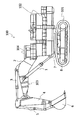
- FIG. 1 is a side view of a hydraulic shovel as an example of a construction machine according to a first embodiment of the present invention.
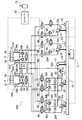
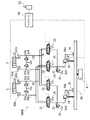
- FIG. 2 is a schematic configuration diagram of a hydraulic drive device mounted on the hydraulic excavator shown in FIG. 1.
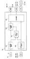
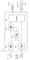
- FIG. 3 is a functional block diagram of the controller shown in FIG. 2.
- FIG. 3 is a diagram showing a behavior of the hydraulic drive device shown in FIG. 2 during a boom raising operation.
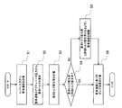
- 3 is a flowchart illustrating a process of the controller illustrated in FIG. 2. It is a figure which shows the relationship between the load torque and rotation speed of a general turbo-equipped engine.
- FIG. 3 is a diagram showing a behavior of the hydraulic drive device shown in FIG. 2 at the time of boom lowering + arm dumping operation.
- FIG. 3 is a view showing a behavior of the hydraulic drive device shown in FIG. 2 at the time of boom raising + arm dumping operation.
- FIG. 6 is a schematic configuration diagram of a hydraulic drive device according to a second embodiment of the present invention.
- 9 is a flowchart illustrating processing of a controller according to a second embodiment of the present invention. It is a figure showing the behavior at the time of boom raising + turning operation of the hydraulic drive in a 2nd example of the present invention. It is a schematic structure figure of a hydraulic drive in a 3rd example of the present invention. It is a functional block diagram of a controller in a 3rd example of the present invention.
- FIG. 1 is a side view of a hydraulic shovel according to a first embodiment of the present invention.
- a hydraulic excavator 100 includes a lower traveling body 101 equipped with a crawler-type traveling device 8, an upper revolving body 102 rotatably mounted on the lower traveling body 101 via a revolving motor 7, and an upper revolving body 102.
- a front work device 103 is attached to the front part of the body 102 so as to be rotatable up and down.
- a cab 104 on which an operator rides is provided on the upper swing body 102.
- the front working device 103 includes a boom 2 attached to a front portion of the upper swing body 102 so as to be rotatable in a vertical direction, and a working member connected to a distal end portion of the boom 2 so as to be rotatable in a vertical or front and rear direction.
- Arm 4 a bucket 6 as a working member rotatably connected to the distal end of the arm 4 in the up-down or front-rear direction, a hydraulic cylinder (hereinafter, boom cylinder) 1 for driving the boom 2, and an arm
- a hydraulic cylinder (hereinafter referred to as an arm cylinder) 3 for driving a hydraulic cylinder 4 and a hydraulic cylinder (hereinafter referred to as a bucket cylinder) 5 for driving a bucket 6 are provided.
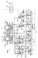
- FIG. 2 is a schematic configuration diagram of a hydraulic drive device mounted on the excavator 100 shown in FIG.
- FIG. 2 shows only parts related to driving of the boom cylinder 1 and the arm cylinder 3, and omits other parts related to driving of the actuator.
- a hydraulic drive device 300 includes a boom cylinder 1, an arm cylinder 3, a lever 51 as an operation device for instructing each operation direction and each required speed of the boom cylinder 1 and the arm cylinder 3, and A certain engine 9, a power transmission device 10 for distributing the power of the engine 9, first to fourth hydraulic pumps 12 to 15 and a charge pump 11 driven by the power distributed by the power transmission device 10, Switching valves 40 to 47 capable of switching the connection between the first to fourth hydraulic pumps 12 to 15 and the hydraulic actuators 1 and 3, proportional valves 48 and 49, switching valves 40 to 47, and proportional valves 48 and 49 , And a controller 50 for controlling regulators 12a, 13a, 14a, 15a to be described later.
- the engine 9 as a power source is connected to a power transmission device 10 for distributing power.
- the first to fourth hydraulic pumps 12 to 15 and the charge pump 11 are connected to the power transmission device 10.
- Each of the first to fourth hydraulic pumps 12 to 15 includes a tilting swash plate mechanism having a pair of input / output ports, and regulators 12a, 13a, 14a, and 15a for adjusting the tilt angle of the tilting swash plate. .
- the regulators 11a, 12a, 13a and 14a adjust the tilt angles of the tilt swash plates of the first to fourth hydraulic pumps 12 to 15 according to a signal from the controller 50.
- the first and second hydraulic pumps 12 and 13 can control the discharge flow rate and direction of hydraulic oil from the input / output port by adjusting the tilt angle of the tilt swash plate.
- the charge pump 11 replenishes the flow path 212 with pressurized oil.
- the first and second hydraulic pumps 12, 13 also function as hydraulic motors when supplied with pressure oil.
- the flow paths 200 and 201 are connected to a pair of input / output ports of the first hydraulic pump 12, and the switching valves 40 and 41 are connected to the flow paths 200 and 201.
- the switching valves 40 and 41 switch communication between the flow paths and cutoff according to a signal from the controller 50.
- the switching valves 40 and 41 are shut off when there is no signal from the controller 50.
- the switching valve 40 is connected to the boom cylinder 1 via the flow paths 210 and 211, respectively.
- the switching valve 40 is brought into a communication state by a signal from the controller 50, the first hydraulic pump 12 is connected to the boom cylinder 1 via the flow paths 200 and 201, the switching valve 40, and the flow paths 210 and 211. This constitutes a closed circuit.
- the switching valve 41 is connected to the arm cylinder 3 via the flow paths 213 and 214, respectively.
- the switching valve 41 is brought into a communication state by a signal from the controller 50, the first hydraulic pump 12 is connected to the arm cylinder 3 via the flow paths 200 and 201, the switching valve 41, and the flow paths 213 and 214. This constitutes a closed circuit.
- the flow paths 202 and 203 are connected to a pair of input / output ports of the second hydraulic pump 13, and the switching valves 42 and 43 are connected to the flow paths 202 and 203.
- the switching valves 42 and 43 switch communication and cutoff of the flow path in accordance with a signal from the controller 50. When there is no signal from the controller 50, the switching valves 42 and 43 are shut off.
- the switching valve 42 is connected to the boom cylinder 1 via the flow paths 210 and 211, respectively.
- the switching valve 42 is brought into a communication state by a signal from the controller 50, the second hydraulic pump 13 is connected to the boom cylinder 1 through the flow paths 202 and 203, the switching valve 42, and the flow paths 210 and 211. This constitutes a closed circuit.
- the switching valve 43 is connected to the arm cylinder 3 via the flow paths 213 and 214, respectively.
- the switching valve 43 is brought into a communication state by a signal from the controller 50, the second hydraulic pump 13 is connected to the arm cylinder 3 via the flow paths 202 and 203, the switching valve 43, and the flow paths 213 and 214. This constitutes a closed circuit.
- One of the pair of input / output ports of the third hydraulic pump 14 is connected to the switching valves 44 and 45, the proportional valve 48, and the relief valve 21 via the flow path 204.
- the opposite sides of the pair of input / output ports of the third hydraulic pump 14 are connected to a tank 25.
- the relief valve 21 allows the hydraulic oil to escape to the tank 25 when the flow path pressure becomes equal to or higher than a predetermined pressure, thereby protecting the circuit.
- the switching valves 44 and 45 switch communication and cutoff of the flow path in accordance with a signal from the controller 50. When there is no signal from the controller 50, the switching valves 44 and 45 are shut off.
- the switching valve 44 is connected to the boom cylinder 1 via the flow path 210.
- the switching valve 45 is connected to the arm cylinder 3 via the flow path 213.
- the proportional valve 48 changes the opening area in response to a signal from the controller 50 to control the flow rate. In the absence of a signal from the controller 50, the proportional valve 48 is held at the maximum open area. When the switching valves 44 and 45 are shut off, the controller 50 sends a signal to the proportional valve 48 so that the opening area is determined in advance according to the discharge flow rate of the third hydraulic pump 14.
- One side of the pair of input / output ports of the fourth hydraulic pump 15 is connected to the switching valves 46 and 47, the proportional valve 49, and the relief valve 22 via the flow path 205.
- the opposite side of the pair of input / output ports of the fourth hydraulic pump 15 is connected to the tank 25.
- the relief valve 22 releases the hydraulic oil to the tank 25 when the flow path pressure becomes equal to or higher than a predetermined pressure to protect the circuit.
- the switching valves 46 and 47 switch communication and cutoff of the flow path in accordance with a signal from the controller 50. When there is no signal from the controller 50, the switching valves 46 and 47 are in the shut-off state.
- the switching valve 46 is connected to the boom cylinder 1 via the flow path 210.
- the switching valve 47 is connected to the arm cylinder 3 via the flow path 213.
- the proportional valve 49 changes the opening area in response to a signal from the controller 50 to control the flow rate. When there is no signal from the controller 50, the proportional valve 49 is held at the maximum opening area. When the switching valves 46 and 47 are in the shut-off state, the controller 50 sends a signal to the proportional valve 49 so that the opening area is determined in advance according to the discharge flow rate of the fourth hydraulic pump 15.
- the discharge port of the charge pump 11 is connected to the charge relief valve 20 and the charge check valves 26, 27, 28a, 28b, 29a, 29b via the flow path 212.
- the suction port of the charge pump 11 is connected to the tank 25.
- the charging relief valve 20 adjusts the charging pressure of the charging check valves 26, 27, 28a, 28b, 29a, 29b.
- the charging check valve 26 supplies the pressure oil of the charge pump 11 to the flow paths 200 and 201 when the pressure in the flow paths 200 and 201 falls below the pressure set by the charging relief valve 20.
- the charging check valve 27 supplies the pressure oil of the charge pump 11 to the flow paths 202 and 203 when the pressure in the flow paths 202 and 203 falls below the pressure set by the charging relief valve 20.
- the charge check valves 28a and 28b supply the pressure oil of the charge pump 11 to the flow paths 210 and 211 when the pressure in the flow paths 210 and 211 falls below the pressure set by the charge relief valve 20.
- the charge check valves 29a and 29b supply the pressure oil of the charge pump 11 to the flow paths 213 and 214 when the pressure in the flow paths 213 and 214 falls below the pressure set by the charge relief valve 20.
- the relief valves 30a, 30b provided in the flow paths 200, 201 allow the hydraulic oil to escape to the tank 25 via the charging relief valve 20 when the flow path pressure exceeds a predetermined pressure, thereby protecting the circuit. I do.
- the relief valves 31a and 31b provided in the flow paths 202 and 203 allow the hydraulic oil to escape to the tank 25 via the charging relief valve 20 and protect the circuit when the flow path pressure becomes equal to or higher than a predetermined pressure. I do.
- the flow path 210 is connected to the head chamber 1 a of the boom cylinder 1.
- the flow path 211 is connected to the rod chamber 1b of the boom cylinder 1.
- the boom cylinder 1 is a hydraulic single rod cylinder that expands and contracts by receiving a supply of hydraulic oil.
- the expansion and contraction direction of the boom cylinder 1 depends on the supply direction of the hydraulic oil.
- the relief valves 32a and 32b provided in the flow paths 210 and 211 allow the hydraulic oil to escape to the tank 25 via the charging relief valve 20 and protect the circuit when the flow path pressure becomes equal to or higher than a predetermined pressure. I do.
- the flushing valve 34 provided in the flow paths 210 and 211 discharges excess oil in the flow path to the tank 25 via the charging relief valve 20.
- the flow path 213 is connected to the head chamber 3 a of the arm cylinder 3.
- the flow path 214 is connected to the rod chamber 3 b of the arm cylinder 3.
- the arm cylinder 3 is a hydraulic single rod cylinder that expands and contracts by receiving a supply of hydraulic oil.
- the direction of expansion and contraction of the arm cylinder 3 depends on the direction of supply of hydraulic oil.
- the relief valves 33a and 33b provided in the flow paths 213 and 214 allow the hydraulic oil to escape to the tank 25 via the charging relief valve 20 and protect the circuit when the flow path pressure becomes equal to or higher than a predetermined pressure. I do.
- the flushing valve 35 provided in the flow paths 210 and 211 discharges excess oil in the flow path to the tank 25 via the charging relief valve 20.
- the pressure sensor 60a connected to the flow path 210 measures the pressure in the flow path 210 and inputs the measured pressure to the controller 50.
- the pressure sensor 60a measures the head chamber pressure of the boom cylinder 1 by measuring the pressure of the flow path 210.
- the pressure sensor 60b connected to the flow path 211 measures the pressure in the flow path 211 and inputs the measured pressure to the controller 50.
- the pressure sensor 60b measures the rod chamber pressure of the boom cylinder 1 by measuring the pressure of the flow path 211.
- the pressure sensor 61a connected to the flow path 213 measures the pressure in the flow path 213 and inputs the measured pressure to the controller 50.
- the pressure sensor 61a measures the head chamber pressure of the arm cylinder 3 by measuring the pressure of the flow path 213.
- the pressure sensor 61b connected to the flow path 214 measures the pressure in the flow path 214 and inputs the measured pressure to the controller 50.
- the pressure sensor 61b measures the pressure of the rod chamber of the arm cylinder 3 by measuring the pressure of the flow path 214.
- the lever 51 inputs an operation amount of each actuator from the operator to the controller 50.
- FIG. 3 is a functional block diagram of the controller 50 shown in FIG. In FIG. 3, as in FIG. 2, only a part related to driving the boom cylinder 1 and the arm cylinder 3 is shown, and other parts related to driving the actuator are omitted.
- the controller 50 includes a required speed calculating unit 50a, an actuator pressure calculating unit 50b, a required torque estimating unit 50c, a required speed limiting unit 50d, and a command calculating unit 50e.
- the requested speed calculation unit 50a calculates the operation direction and requested speed of each actuator in response to an operator's lever input, and outputs the calculation to the requested torque estimation unit 50c and the requested speed limit unit 50d.
- the actuator pressure calculation unit 50b calculates the pressures of the actuators 1 and 3 (hereinafter, actuator pressures) from the values of the pressure sensors 60a, 60b, 61a and 61b provided in each unit, and calculates a required torque estimation unit 50c and a command calculation unit. Output to 50e.
- the required torque estimating unit 50c drives the actuators 1 and 3 based on the required speed input from the required speed calculating unit 50a and the actuator pressure input from the actuator pressure calculating unit 50b in response to an operator's lever input. Then, the torque applied to the engine 9 (hereinafter, required torque) is estimated.
- the required speed limiting unit 50d calculates a required torque change rate (hereinafter, required torque change rate) based on the required torque input from the required torque estimation unit 50c. Then, the request speed input from the request speed calculation unit 50a is limited so that the request torque change rate does not exceed an allowable torque change rate (described later) set in advance based on the characteristics of the engine 9, and the command calculation unit 50e. Output to a required torque change rate (hereinafter, required torque change rate) based on the required torque input from the required torque estimation unit 50c. Then, the request speed input from the request speed calculation unit 50a is limited so that the request torque change rate does not exceed an allowable torque change rate (described later) set in advance based on the characteristics of the engine 9, and the command calculation unit 50e. Output to
- the command calculation unit 50e is configured to control the switching valves 40 to 47, the proportional valves 48 and 49, and the regulators 12a and 13a based on the actuator pressure input from the actuator pressure calculation unit 50b and the required speed input from the required speed limit unit 50d. , 14a and 15a are calculated.
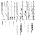
- FIG. 4 shows the input of the lever 51, the required cylinder speed based on the input of the lever 51, and the first hydraulic pump 12 when the boom cylinder 1 is extended by the hydraulic pressure driving device 300. And the sum of the required discharge flow rate of the third hydraulic pump 14 and the required discharge flow rate of the fourth hydraulic pump 15, the pressure sensors 60a and 60b. , The head chamber pressure and rod chamber pressure of the boom cylinder 1, the engine load torque, the discharge flow rate of the first hydraulic pump 12, the discharge flow rate of the second hydraulic pump 13, and the discharge rate of the third hydraulic pump 14. The change in the flow rate and the discharge flow rate of the fourth hydraulic pump 15 is shown.
- the input value of the lever 51 causes the command value for extending the boom cylinder 1 to be increased to the maximum value.
- FIG. 5 is a flowchart showing a flow of the pump load torque control of the controller 50.
- step S1 the controller 50 determines the required cylinder speed Vcyl_d from the input value Lin of the lever 51.
- step S2 the controller 50 calculates the sum Qcp_d of the required discharge flow rate of the first hydraulic pump 12 and the required discharge flow rate of the second hydraulic pump 13 from the required cylinder speed Vcyl_d, and the third hydraulic pressure.
- the sum Qop_d of the required discharge flow rate of the pump 14 and the required discharge flow rate of the fourth hydraulic pump 15 is calculated as follows, for example.
- step S2 the controller 50 controls the head chamber pressure Pcyl_h and rod chamber pressure Pcyl_r of the boom cylinder 1 measured by the pressure sensors 60a and 60b, the required discharge flow rate of the first hydraulic pump 12, and the second hydraulic pump.
- the boom cylinder 1 was driven according to the input of the lever 51 from the sum Qcp_d of the required discharge flow rates of the thirteenth and Qop_d of the required discharge flow rates of the third hydraulic pump 14 and the fourth hydraulic pump 15.
- the required torque Tp_d generated by the first to fourth hydraulic pumps 12 to 15 is calculated, for example, as follows.
- Neng is the engine speed
- Ploss is the pressure loss generated in the pipe from the cylinder to the pump
- ⁇ cp is the pump efficiency of the first hydraulic pump 12 and the second hydraulic pump 13.
- ⁇ op is the pump efficiency of the third hydraulic pump 14 and the fourth hydraulic pump 15.
- step S3 the change rate of the required torque Tp_d (the required torque change rate) is calculated.
- the required torque change rate is obtained, for example, by dividing a value obtained by subtracting the torque currently output by the engine 9 from the required torque Tp_d by the control cycle of the controller 50.
- step S4 the controller 50 proceeds to step S6 if the required torque change rate calculated in step S3 is equal to or less than the change rate of the allowable torque Tp_lim (hereinafter, the allowable torque change rate). Proceed to S5.
- the allowable torque Tp_lim is a torque that can be output by the engine 9 and can be calculated from information such as the fuel injection amount of the engine 9 and the turbo pressure.
- the allowable torque Tp_lim and the allowable torque change rate may be obtained as follows.
- the maximum torque change rate at which the decrease in the engine speed is suppressed to the allowable minimum speed is set as the allowable torque change rate, and the maximum output torque that satisfies the allowable torque change rate is set as the allowable torque Tp_lim.
- the allowable torque Tp_lim it is obtained by adding the product of the allowable torque change rate and the control cycle of the controller 50 to the current engine output torque. That is, the allowable torque Tp_lim in the present invention changes every moment according to the current engine output torque.
- step S4 it is determined whether the required torque change rate is equal to or less than the allowable torque change rate. This determination is the same as the determination as to whether the required torque Tp_d is equal to or less than the allowable torque Tp_lim. is there.
- step S5 the controller 50 limits the required cylinder speed Vcyl_d so that the required torque change rate is equal to or less than the allowable torque change rate (that is, the required torque Tp_d is equal to or less than the allowable torque Tp_lim).
- the engine 9 can output only the allowable torque Tp_lim with respect to the required torque Tp_d obtained in step S2, the sum Tcp_d of the required torque of the first hydraulic pump 12 and the required torque of the second hydraulic pump 13, and The sum Top_d of the required torque of the third hydraulic pump 14 and the required torque of the fourth hydraulic pump 15 is
- step S6 the controller 50 determines, based on the required cylinder speed Vcyl_d, the required discharge flow rate Qcp1_d of the first hydraulic pump 12, the required discharge flow rate Qcp2_d of the second hydraulic pump 13, and the request of the third hydraulic pump 14.
- the discharge flow rate Qop1_d and the required discharge flow rate Qop2_d of the fourth hydraulic pump 15 are calculated.
- the controller 50 calculates the sum of the required discharge flow rate of the first hydraulic pump 12 and the required discharge flow rate of the second hydraulic pump 13 from the required cylinder speed Vcyl_d using equations (2) and (4).
- Qcp_d is calculated, and the sum Qop_d of the required discharge flow rate of the third hydraulic pump 14 and the required discharge flow rate of the fourth hydraulic pump 15 is calculated using equations (3) and (5).
- the controller 50 calculates the required torque from the calculated required discharge flow rate and the head chamber pressure and the rod chamber pressure of the boom cylinder 1 measured by the pressure sensors 60a and 60b, using equations (8), (9), and (10). Calculate Tp_d.
- the required torque Tp_d increases to the maximum value from time t1 to time t2, while the allowable torque Tp_lim of the engine 9 becomes the rated maximum torque of the engine 9 from time t1 to time t3.
- the controller 50 calculates the restricted cylinder speed Vcyl_d 'using Expression (15) such that the required torque Tp_d is equal to or less than the allowable torque Tp_lim of the engine 9.
- the controller 50 determines the discharge flow rate Qcp12 of the first hydraulic pump 12, the discharge flow rate Qcp13 of the second hydraulic pump 13, the required discharge flow rate Qop14 of the third hydraulic pump 14, And the required discharge flow rate Qop15 of the fourth hydraulic pump 15 is calculated.
- the excavator 100 can be operated without causing the engine 9 to lag down.
- the horsepower is calculated based on the actuator pressure
- the engine speed is stabilized and the pressure fluctuation is equal to or less than a specified value.
- the fluctuation of the actuator pressure may be suppressed by a filtering process such as a moving average.
- the pumps are started one by one, but they may be started at the same time.
- FIG. 7 shows the input of the lever 51 and the input of the lever 51 when the hydraulic drive device 300 simultaneously performs the contraction operation of the boom cylinder 1 and the contraction operation of the arm cylinder 3.
- Required discharge flow rates of the hydraulic pumps 12 and 13 required flow rates of the proportional valves 48 and 49, engine load torque, respective discharge flow rates of the first and second hydraulic pumps 12 and 13, and the proportional valves 48 and 49. The change of each passing flow rate is shown.
- the controller 50 allocates the first hydraulic pump 12 for driving the boom cylinder 1 and allocates the second hydraulic pump 13 for driving the arm cylinder 3.
- the controller 50 calculates the required discharge flow rate Qcp12_d of the first hydraulic pump 12 from the required boom cylinder speed Vcyl_boom_d using the equations (2) and (4). Further, the controller 50 calculates the required discharge flow rate Qcp13_d of the second hydraulic pump 13 from the required arm cylinder speed Vcyl_arm_d by using equations (2) and (4).
- the controller 50 allocates the proportional valve 48 for discharging the surplus flow rate of the boom cylinder 1 and the proportional valve 49 for discharging the surplus flow rate of the arm cylinder 3.
- the controller 50 calculates the required passage flow rate Qpv48_d of the proportional valve 48 from the required boom cylinder speed Vcyl_boom_d using equations (3) and (16). Further, the controller 50 calculates the required passage flow rate Qpv49_d of the proportional valve 49 from the required arm cylinder speed Vcyl_arm_d by using equations (3) and (16).
- the controller 50 calculates the calculated required flow rate, the head chamber pressure and the rod chamber pressure of the boom cylinder 1 measured by the pressure sensors 60a and 60b, and the head chamber pressure and the rod chamber pressure of the arm cylinder 3 measured by the pressure sensors 61a and 61b.
- the required torque Tp_d is calculated by using equations (8) and (10).
- the discharge pressure of the first hydraulic pump 12 becomes higher than the suction pressure when raising the boom to extend the boom cylinder 1.
- the first hydraulic pump 12 operates as a pump.
- the suction pressure of the first hydraulic pump 12 becomes higher than the discharge pressure, so that the first hydraulic pump 12 operates as a motor.
- the discharge pressure of the second hydraulic pump 13 becomes higher than the suction pressure during arm dump when the arm cylinder 3 contracts.
- the second hydraulic pump 13 operates as a pump.
- the suction pressure of the second hydraulic pump 13 becomes higher than the discharge pressure, so that the second hydraulic pump 13 operates as a motor.
- the first hydraulic pump 12 when the input of the lever 51 is lowered and the arm is dumped, the first hydraulic pump 12 operates as a motor and the second hydraulic pump 13 operates as a pump.
- the sum of the required torque and the required torque of the second hydraulic pump 13, Tcp_d, is lower than when the first hydraulic pump 12 and the second hydraulic pump 13 both operate as pumps alone.
- the excavator 100 can be operated without causing the engine 9 to lag down.
- the vibration of the actuator pressure may be suppressed by a filtering process such as a moving average.
- FIG. 8 shows the input of the lever 51 and the input of the lever 51 when the extension operation of the boom cylinder 1 and the contraction operation of the arm cylinder 3 are simultaneously performed by the hydraulic pressure driving device 300.
- the input value of the lever 51 increases the command value for extending the boom cylinder 1 and the command value for contracting the arm cylinder 3 to the maximum value.
- the controller 50 controls the first hydraulic pump 12 and the third hydraulic pump 14 for driving the boom cylinder 1 and the second hydraulic pump 13 and the proportional valve 49 for driving the arm cylinder 3. assign.
- the controller 50 calculates the required discharge flow rate Qcp12_d of the first hydraulic pump 12 from the required boom cylinder speed Vcyl_boom_d using the equations (2) and (4). Further, the controller 50 calculates the required discharge flow rate Qcp13_d of the second hydraulic pump 13 from the required arm cylinder speed Vcyl_arm_d by using equations (2) and (4).
- the controller 50 calculates the required discharge flow rate Qop14_d of the third hydraulic pump 14 from the required boom cylinder speed Vcyl_boom_d using the equations (3) and (5).
- the controller 50 calculates the required passage flow rate Qpv49_d of the proportional valve 49 from the required arm cylinder speed Vcyl_arm_d by using equations (3) and (16).
- the controller 50 calculates the calculated required flow rate, the head chamber pressure and the rod chamber pressure of the boom cylinder 1 measured by the pressure sensors 60a and 60b, and the head chamber pressure and the rod chamber pressure of the arm cylinder 3 measured by the pressure sensors 61a and 61b.
- the required torque Tcp12_d of the first hydraulic pump 12 the required torque Tcp13_d of the second hydraulic pump 13, and the required torque Top14_d of the third hydraulic pump 14 are calculated. I do. At this time, the required torque Tp_d is
- the controller 50 calculates the discharge flow rate Qcp12 of the first hydraulic pump 12 and the required discharge flow rate Qop14 of the third hydraulic pump 14 based on the restricted boom cylinder velocity Vcyl_boom_d ', and calculates the restricted arm cylinder velocity Vcyl_arm_d'. Based on this, the discharge flow rate Qcp13 of the second hydraulic pump 13 and the flow rate Qpv49 of the proportional valve 49 are calculated.
- the engine 9, variable displacement hydraulic pumps 12 to 15 driven by the engine 9, and hydraulic actuators 1 and 3 driven by hydraulic fluid discharged from the hydraulic pumps 12 to 15 Control valves 40 to 47 capable of switching the connection between the hydraulic actuators 1 and 3 and the hydraulic pumps 12 to 15, and pressure detecting devices 60a, 60b and 61a for detecting each load pressure of the hydraulic actuators 1 and 3. 61b, an operation device 51 for instructing each operation direction and each required speed of the hydraulic actuators 1 and 3, and a controller 50 for controlling each discharge flow rate of the hydraulic pumps 12 to 15 according to an input from the operation device 51.
- a required torque estimating unit 50c for estimating a required torque Tp_d which is the sum of the torques required in the case where the required torque change rate, which is a change rate of the required torque Tp_d, exceeds a predetermined change rate (allowable torque change rate).
- a request speed limiter 50d that limits each required speed of the hydraulic actuators 1 and 3 so that the required torque change rate is equal to or less than the predetermined change rate; and a required torque change rate that is a change rate of the required torque.
- a required speed limiting unit 50d for limiting each required speed of the hydraulic actuators 1 and 3 so that the required torque change rate is equal to or less than the predetermined rate of change when the predetermined rate of change is exceeded;
- the assignment of the hydraulic pumps 12 to 15 to the hydraulic actuators 1 and 3 is determined based on the required speeds of the hydraulic actuators 1 and 3 limited by the section 50d.
- a command calculation unit 50e for calculating each discharge flow rate of the pumps 12 to 15.
- Each of the hydraulic pumps 12 and 13 is a double-discharge hydraulic pump having a pair of input / output ports, and the control valves 40 to 43 are connected to the hydraulic pumps 12 and 13 and the hydraulic actuators 1 and 3, respectively. This is a switching valve that can switch the connection of.
- the hydraulic drive device 300 that controls the flow of the hydraulic oil supplied from the two-discharge type hydraulic pumps 12 and 13 to the actuators 1 and 3 by the switching valves 40 to 43.
- the required torque Tp_d for the engine 9 is estimated based on the required speed of the hydraulic actuators 1 and 3 and the load pressure of the hydraulic actuators 1 and 3, and the required torque change rate becomes a predetermined change rate ( When the allowable torque change rate exceeds the allowable torque change rate, the required speed of the hydraulic actuators 1 and 3 is limited so that the required torque change rate is equal to or less than a predetermined change rate. This makes it possible to suppress a lag-down of the engine 9 irrespective of the operation contents of the operator and the load state of the hydraulic actuators 1 and 3.
- the command calculation unit 50e determines that the required torque change rate is a predetermined change rate (allowable torque change rate) in a state where two or more hydraulic pumps are assigned to one of the hydraulic actuators 1 and 3. ), The number of hydraulic pumps allocated to the one hydraulic actuator is reduced according to the required speed of the one hydraulic actuator limited by the required speed limiting unit 50d. This improves the fuel efficiency of the hydraulic pump in use and increases the number of unused hydraulic pumps, thereby facilitating assignment of the hydraulic pump to a newly operated actuator.
- a predetermined change rate allowable torque change rate
- the required cylinder speed Vcyl_d is uniquely determined from the input of the lever 51 by Expression (1).
- the required cylinder speed Vcyl_d is determined by the load state of each actuator and the balance of the input value of the lever 51. May be provided in the controller 50.
- the hydraulic excavator 100 according to the second embodiment of the present invention will be described focusing on the differences from the first embodiment.
- FIG. 9 is a schematic configuration diagram of the hydraulic drive device in the present embodiment.
- the difference from the first embodiment (shown in FIG. 2) is that the arm cylinder 3 is replaced by a swing motor 7.
- the flow path 215 is connected to the port a of the turning motor 7.
- the flow path 216 is connected to the b port of the turning motor 7.
- the turning motor 7 is a hydraulic motor that rotates by receiving a supply of hydraulic oil.
- the rotation direction of the swing motor 7 depends on the supply direction of the working oil.
- the relief valves 37a and 37b provided in the flow passages 215 and 216 allow the hydraulic oil to escape to the tank 25 via the charging relief valve 20 and protect the circuit when the flow passage pressure becomes equal to or higher than a predetermined pressure. I do.
- the flushing valve 38 provided in the flow passages 215 and 216 discharges excess oil in the flow passage to the tank 25 via the charging relief valve 20.
- the pressure sensor 62 a connected to the flow path 215 measures the pressure in the flow path 215 and inputs the measured pressure to the controller 50.
- the pressure sensor 62a measures the pressure in the flow path 215 to measure the a-port pressure Pswing_a of the swing motor 7.
- the pressure sensor 62b connected to the flow path 216 measures the pressure in the flow path 216 and inputs the measured pressure to the controller 50.
- the pressure sensor 62b measures the b-port pressure Pswing_b of the swing motor 7 by measuring the pressure in the flow path 216.
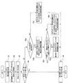
- FIG. 10 is a flowchart showing a flow of the pump load torque control of the controller 50 shown in FIG. 10 differs from the first embodiment (shown in FIG. 5) in that steps S5a to S5f are provided instead of step S5.
- steps S5a to S5f are provided instead of step S5.
- step S5a the controller 50 proceeds to step S5b if the combined operation of the boom and the turn is performed, and proceeds to step S5f otherwise.
- step S5b the controller 50 limits the required speed of the swing motor 7 so that the required torque of the swing motor 7 is equal to or less than a predetermined ratio of the total allowable torque Tp_lim.
- step S5c the controller 50 proceeds to step S5d if the sum of the required torque of the swing motor 7 having the limited required speed and the required torque of the actuators other than the other swing motors 7 exceeds the total allowable torque Tp_lim, and otherwise proceeds to step S5d. In this case, the process proceeds to step S5e.
- step S5d the controller 50 determines a required speed of an actuator other than the swing motor 7 from the input value Lin of the lever 51.
- step S5e the controller 50 limits the required speeds of the actuators other than the swing motor 7 so that the total required torque of each actuator is equal to or less than the total allowable torque Tp_lim while maintaining the required speed ratio of each actuator.
- step S5f the controller 50 limits the required speed of each actuator so that the total required torque of each actuator is equal to or less than the total allowable torque Tp_lim while maintaining the required speed ratio of each actuator.
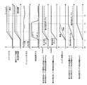
- FIG. 11 is based on the input of the lever 51 and the input of the lever 51 when the extension operation of the boom cylinder 1 and the turning operation of the swing motor 7 are simultaneously performed by the hydraulic pressure driving device 300.
- the change of each required discharge flow rate of the third to third hydraulic pumps 12 to 14, the engine load torque, and the change of each discharge flow rate of the first to third hydraulic pumps 12 to 14 are shown.
- the input value of the lever 51 increases the command value for extending the boom cylinder 1 and the command value for rotating the swing motor 7 to the maximum value.
- the controller 50 allocates the first hydraulic pump 12 and the third hydraulic pump 14 for driving the boom cylinder 1 and the second hydraulic pump 13 for driving the swing motor 7.
- the controller 50 calculates the required discharge flow rate Qcp12_d of the first hydraulic pump 12 from the required boom cylinder speed Vcyl_boom_d using the equations (2) and (4).
- the required discharge flow rate Qcp13_d of the second hydraulic pump 13 is calculated using the equations (25) and (26).
- the controller 50 calculates the required discharge flow rate Qop14_d of the third hydraulic pump 14 from the required boom cylinder speed Vcyl_boom_d using the equations (3) and (5).
- the controller 50 calculates the required flow rate, the head chamber pressure and the rod chamber pressure of the boom cylinder 1 measured by the pressure sensors 60a and 60b, and the a port pressure Pswing_a and the b port pressure of the swing motor 7 measured by the pressure sensors 62a and 62b. From Pswing_a, using equations (8) and (9), the required torque Tcp12_d of the first hydraulic pump 12, the required torque Tcp13_d of the second hydraulic pump 13, and the required torque of the third hydraulic pump 14 Calculate Top14_d. At this time, the required torque Tp_d is
- the required torque Tp_d increases to the maximum value from the time t1 to the time t2, while the allowable torque Tp_lim of the engine 9 becomes the rated maximum torque of the engine 9 from the time t1 to the time t3.
- the controller 50 from time t1 to time t3, the controller 50
- a characteristic is that the port a pressure and the port b pressure are low during stoppage, and the pressure at one port increases during turning acceleration. is there.
- the port pressure on one side rises to the set pressure of the relief valves 37a and 37b. Therefore, when a required speed exceeding the maximum acceleration is input, if a required flow rate is supplied from the pump, a part of the flow rate is discharged from one of the relief valves 37a and 37b to the tank 25 and is wasted.
- the ratio of the horsepower assigned to the swing motor 7 is set lower than the ratio of the horsepower assigned to the boom cylinder 1. That is, 50% or less (for example, 20%) of the horsepower that can be output by the engine 9 is allocated to the turning motor 7. From equation (28),
- the controller 50 calculates the discharge flow rate Qcp12 of the first hydraulic pump 12 and the required discharge flow rate Qop14 of the third hydraulic pump 14 based on the limited boom cylinder speed Vcyl_boom_d ', and based on the limited swing speed Wswing_d'. , The discharge flow rate Qcp13 of the second hydraulic pump 13 is calculated.
- the hydraulic actuators 1 and 7 include one or more hydraulic cylinders 1 and one or more hydraulic motors 7, and the command calculation unit 50e includes the hydraulic cylinder 1 and the hydraulic motor 7
- the required torque change rate exceeds a predetermined change rate (permissible torque change rate) in a state where the motors are simultaneously driven, the required torque of the hydraulic pump assigned to the hydraulic motor 7 is changed to the output torque of the engine 9.
- the respective discharge flow rates of the hydraulic pumps 12 to 15 are calculated so as to be equal to or less than a predetermined ratio (for example, 20%).
- the engine 9 is lagged down while the speed of the boom cylinder 1 is not significantly reduced due to the pressure increase of the swing motor 7 at the start of swing.
- the excavator 100 can be operated without the need for this.
- FIG. 12 is a schematic configuration diagram of the hydraulic drive device in the present embodiment
- FIG. 13 is a functional block diagram of the controller 50 in the present embodiment. 12 and 13, the difference from the first embodiment (shown in FIGS. 2 and 3) is that the components of the closed circuit are eliminated, and that the hydraulic pumps 13 and 14 and the hydraulic actuators 1 and 2 are different. 3 in that the switching valves 44 to 47 capable of switching the connection with the third valve 3 are replaced with flow control valves 71 to 74.
- the flow control valve 71 is connected to the flow path 204, the tank 25, the flow path 210, and the flow path 211.
- the flow control valve 72 connects the flow path 204 and the tank 25 and closes a port connected to the flow path 210 and the flow path 211.
- the flow control valve 71 connects the flow path 204 and the flow path 210, and connects the tank 25 and the flow path 211.
- the flow control valve 71 connects the flow path 204 to the flow path 211 and connects the tank 25 to the flow path 210.
- the opening area of the flow path connecting each flow path changes according to the magnitude of the positive or negative signal.
- the flow control valve 72 is connected to the flow path 204, the tank 25, the flow path 213, and the flow path 214. When there is no signal at the flow control valve 72, the flow control valve 72 connects the flow path 204 and the tank 25, and closes the ports connected to the flow paths 213 and 214. When a positive signal is input to the flow control valve 72, the flow control valve 72 connects the flow path 204 and the flow path 213, and connects the tank 25 and the flow path 214. When a negative signal is input, the flow control valve 71 connects the flow path 204 to the flow path 214 and connects the tank 25 to the flow path 213. The opening area of the flow path connecting each flow path changes according to the magnitude of the positive or negative signal.
- the flow control valve 73 is connected to the flow path 205, the tank 25, the flow path 210, and the flow path 211.
- the flow control valve 73 connects the flow path 205 to the tank 25 and closes a port connected to the flow path 210 and the flow path 211.
- the flow control valve 73 connects the flow path 205 to the flow path 210 and connects the tank 25 to the flow path 211.
- a negative signal is input, the flow control valve 73 connects the flow path 205 to the flow path 211 and connects the tank 25 to the flow path 210.
- the opening area of the flow path connecting each flow path changes according to the magnitude of the positive or negative signal.
- the flow control valve 74 is connected to the flow path 205, the tank 25, the flow path 213, and the flow path 214.
- the flow control valve 72 connects the flow path 205 and the tank 25, and closes the ports connected to the flow paths 213 and 214.
- the flow control valve 74 connects the flow path 205 and the flow path 213, and connects the tank 25 and the flow path 214.
- the flow control valve 74 connects the flow path 205 to the flow path 214 and connects the tank 25 to the flow path 213.
- the opening area of the flow path connecting each flow path changes according to the magnitude of the positive or negative signal.
- the demands of the actuators determined by the input of the lever 51 can be determined in the same manner as in the first embodiment. It is possible to operate the excavator 100 without lagging down the engine 9 while maintaining the speed ratio. If the flow control valves 71 to 74 are used with the maximum opening area and the speeds of the boom cylinder 1 and the arm cylinder 3 are controlled by the discharge flow rates of the hydraulic pumps 14 and 15, the flow control valves 71 to 74 are generated. The resulting pressure loss is easier to estimate.
- the hydraulic excavator 100 includes hydraulic pumps 13 and 14, hydraulic actuators 1 and 3, and control valves 71 to which connection between the hydraulic actuators 1 and 3 and the hydraulic pumps 13 and 14 can be switched.
- the pressure detecting devices 60a, 60b, 61a, 61b can detect the respective load pressures of the hydraulic actuators 1, 3, and the operating device 51 can control the operating directions and the operating directions of the hydraulic actuators 1, 3 respectively.
- the required speed can be instructed, and the required torque estimating unit 50c calculates the sum of the torques required by the hydraulic pumps 13 and 14 for the engine 9 based on the required speeds and the load pressures of the hydraulic actuators 1 and 3.
- the required speed limiting unit 50d determines that the required torque change rate, which is the rate of change of the required torque, exceeds a predetermined rate of change (permissible torque change rate).
- the required speeds of the hydraulic actuators 1 and 3 are limited so that the rate of change becomes equal to or less than the predetermined change rate.
- the assignment of the hydraulic pumps 13 and 14 to the hydraulic actuators 1 and 3 is determined based on the required speed, and the respective discharge flow rates of the hydraulic pumps 13 and 14 are calculated.
- the hydraulic pumps 14 and 15 are single-discharge hydraulic pumps each having a suction port and a discharge port, and can switch the connection between the hydraulic actuators 1 and 3 and the hydraulic pumps 14 and 15.
- the control valves 71 to 74 are flow rate control valves capable of adjusting the direction and flow rate of the hydraulic fluid supplied from the hydraulic pumps 14 and 15 to the hydraulic actuators 1 and 3.
- the hydraulic drive 300B equipped with the hydraulic drive device 300B capable of switching the connection between the hydraulic actuators 1, 3 and the hydraulic pumps 13, 14 by the flow control valves 71 to 74 is mounted.
- the shovel 100 as in the first embodiment, it is possible to suppress the engine 9 from lagging down regardless of the operation content of the operator and the load state of the actuators 1 and 3.
- the present invention is not limited to the above-described embodiments, and includes various modifications.
- the above-described embodiments have been described in detail for easy understanding of the present invention, and are not necessarily limited to those having all the configurations described above. It is also possible to add a part of the configuration of another embodiment to the configuration of a certain embodiment, delete a part of the configuration of one embodiment, or replace it with a part of another embodiment. It is possible.
- Power Transmission device 11: charge pump, 12: first hydraulic pump, 12a: regulator, 13: second hydraulic pump, 13a: regulator, 14: third hydraulic pump, 14a: regulator, 15: first 4 hydraulic pump, 15a regulator, 20 relief valve for charging, 21, 22 relief valve, 25 tank, 26, 27, 28a, 2 b, 29a, 29b ... charge check valve, 30a, 30b, 31a, 31b, 32a, 32b, 33a, 33b ... relief valve, 34, 35 ... flushing valve, 36a, 36b ... charge check valve, 37a, 37b ...
- Relief valve, 38 Flushing valve, 40 to 47: Switching valve (control valve), 48, 49: Proportional valve, 50: Controller, 50a: Requested speed calculator, 50b: Actuator pressure calculator, 50c: Requested torque estimator , 50d: required speed limiter, 50e: command calculator, 51: lever (operating device), 60a, 60b, 61a, 61b, 62a, 62b: pressure sensor (pressure detecting device), 71 to 74: flow control valve ( Control valve), 100: hydraulic excavator, 101: lower traveling structure, 102: upper revolving structure, 103: front working device, 104: Catcher Bed, 200-216 ... passage, 300, 300A, 300B ... hydraulic drive.
Landscapes
- Engineering & Computer Science (AREA)
- General Engineering & Computer Science (AREA)
- Mining & Mineral Resources (AREA)
- Civil Engineering (AREA)
- Structural Engineering (AREA)
- Physics & Mathematics (AREA)
- Fluid Mechanics (AREA)
- Mechanical Engineering (AREA)
- Chemical & Material Sciences (AREA)
- Analytical Chemistry (AREA)
- Operation Control Of Excavators (AREA)
- Fluid-Pressure Circuits (AREA)
Abstract
La présente invention aborde le problème de l'utilisation d'un engin de chantier pouvant supprimer le freinage du moteur indépendamment du contenu d'une manœuvre effectuée par un opérateur ou de l'état de charge d'un actionneur hydraulique. À cet effet, un dispositif de commande (50) comprend : une unité (50c) d'estimation de couple demandé destinée, en fonction d'une vitesse demandée d'un premier actionneur hydraulique (1) et d'une pression de charge du premier actionneur hydraulique, à estimer un couple demandé, c'est-à-dire le couple demandé à partir d'un moteur (9) par une première pompe hydraulique ; une unité (50d) de limitation de vitesse demandée destinée, lorsqu'un taux de variation de couple demandé, c'est-à-dire le taux de variation du couple demandé, dépasse un taux de variation prescrit, à limiter la vitesse demandée de sorte que le taux de variation de couple demandé ne soit pas supérieur au taux de variation prescrit ; et une unité (50e) de calcul de commande destinée à calculer un débit de refoulement de la première pompe hydraulique en fonction de la vitesse demandée du premier actionneur hydraulique ayant été limitée par l'unité de limitation de vitesse demandée.
Priority Applications (3)
| Application Number | Priority Date | Filing Date | Title |
|---|---|---|---|
| EP19825561.4A EP3779210B1 (fr) | 2018-06-25 | 2019-05-20 | Engin de chantier |
| US17/056,288 US11118328B2 (en) | 2018-06-25 | 2019-05-20 | Construction machine |
| CN201980033960.9A CN112154271B (zh) | 2018-06-25 | 2019-05-20 | 工程机械 |
Applications Claiming Priority (2)
| Application Number | Priority Date | Filing Date | Title |
|---|---|---|---|
| JP2018119638A JP6934454B2 (ja) | 2018-06-25 | 2018-06-25 | 建設機械 |
| JP2018-119638 | 2018-06-25 |
Publications (1)
| Publication Number | Publication Date |
|---|---|
| WO2020003811A1 true WO2020003811A1 (fr) | 2020-01-02 |
Family
ID=68986345
Family Applications (1)
| Application Number | Title | Priority Date | Filing Date |
|---|---|---|---|
| PCT/JP2019/019879 WO2020003811A1 (fr) | 2018-06-25 | 2019-05-20 | Engin de chantier |
Country Status (5)
| Country | Link |
|---|---|
| US (1) | US11118328B2 (fr) |
| EP (1) | EP3779210B1 (fr) |
| JP (1) | JP6934454B2 (fr) |
| CN (1) | CN112154271B (fr) |
| WO (1) | WO2020003811A1 (fr) |
Families Citing this family (6)
| Publication number | Priority date | Publication date | Assignee | Title |
|---|---|---|---|---|
| DE102018117949A1 (de) * | 2018-07-25 | 2020-01-30 | Putzmeister Engineering Gmbh | Hydrauliksystem und Verfahren zum Steuern eines Hydrauliksystems |
| JP7090567B2 (ja) * | 2019-01-25 | 2022-06-24 | 日立建機株式会社 | 建設機械 |
| CN110762071B (zh) * | 2019-11-01 | 2021-07-06 | 中国海洋石油集团有限公司 | 一种用于井下设备的液压动力系统及井下设备 |
| US20230085676A1 (en) * | 2020-10-19 | 2023-03-23 | Hitachi Construction Machinery Co., Ltd. | Construction Machine |
| CN113062378B (zh) * | 2021-03-25 | 2022-04-08 | 山推工程机械股份有限公司 | 一种推土机主动安全与制动压力的自适应控制方法及系统 |
| JP2024052373A (ja) * | 2022-09-30 | 2024-04-11 | 日立建機株式会社 | 作業機械 |
Citations (4)
| Publication number | Priority date | Publication date | Assignee | Title |
|---|---|---|---|---|
| WO1998006936A1 (fr) * | 1996-08-09 | 1998-02-19 | Komatsu Ltd. | Unite de commande pour moteur et pompe hydraulique a cylindree variable |
| JP2010276126A (ja) | 2009-05-29 | 2010-12-09 | Kobe Steel Ltd | 制御装置及びこれを備えた作業機械 |
| JP2015098938A (ja) * | 2013-10-16 | 2015-05-28 | 株式会社堀内機械 | 液圧装置および液圧装置の制御方法 |
| JP2017106251A (ja) * | 2015-12-10 | 2017-06-15 | 日立建機株式会社 | 作業機械の駆動装置 |
Family Cites Families (15)
| Publication number | Priority date | Publication date | Assignee | Title |
|---|---|---|---|---|
| JPS57197336A (en) * | 1981-05-29 | 1982-12-03 | Komatsu Ltd | Oil-pressure circuit for turning excavator |
| JP3444503B2 (ja) * | 1993-03-26 | 2003-09-08 | 株式会社小松製作所 | 油圧駆動機械の制御装置 |
| JP2005061298A (ja) * | 2003-08-11 | 2005-03-10 | Kobelco Contstruction Machinery Ltd | 建設機械 |
| JP4272485B2 (ja) * | 2003-08-28 | 2009-06-03 | 日立建機株式会社 | 建設機械のエンジンラグダウン抑制装置 |
| JP4794468B2 (ja) * | 2007-01-22 | 2011-10-19 | 日立建機株式会社 | 建設機械のポンプ制御装置 |
| KR100919436B1 (ko) * | 2008-06-03 | 2009-09-29 | 볼보 컨스트럭션 이키프먼트 홀딩 스웨덴 에이비 | 복수의 가변용량형 유압펌프 토오크 제어시스템 및 그제어방법 |
| JP5383537B2 (ja) * | 2010-02-03 | 2014-01-08 | 日立建機株式会社 | 油圧システムのポンプ制御装置 |
| CN104285014B (zh) * | 2012-05-01 | 2016-11-16 | 日立建机株式会社 | 混合动力式作业机械 |
| US9371898B2 (en) * | 2012-12-21 | 2016-06-21 | Cnh Industrial America Llc | Control system for a machine with a dual path electronically controlled hydrostatic transmission |
| KR102014547B1 (ko) * | 2013-03-21 | 2019-08-26 | 두산인프라코어 주식회사 | 건설기계용 유압펌프 제어 장치 |
| KR102015141B1 (ko) * | 2013-03-29 | 2019-08-27 | 두산인프라코어 주식회사 | 건설기계 유압펌프 제어 장치 및 방법 |
| JP6134614B2 (ja) * | 2013-09-02 | 2017-05-24 | 日立建機株式会社 | 作業機械の駆動装置 |
| JP6328548B2 (ja) * | 2014-12-23 | 2018-05-23 | 日立建機株式会社 | 作業機械 |
| JP6738782B2 (ja) * | 2017-09-14 | 2020-08-12 | 日立建機株式会社 | 建設機械の駆動装置 |
| EP4123094A1 (fr) * | 2018-09-10 | 2023-01-25 | Artemis Intelligent Power Limited | Engin industriel avec systeme de controle pour la pompe/moteur |
-
2018
- 2018-06-25 JP JP2018119638A patent/JP6934454B2/ja active Active
-
2019
- 2019-05-20 EP EP19825561.4A patent/EP3779210B1/fr active Active
- 2019-05-20 CN CN201980033960.9A patent/CN112154271B/zh active Active
- 2019-05-20 WO PCT/JP2019/019879 patent/WO2020003811A1/fr unknown
- 2019-05-20 US US17/056,288 patent/US11118328B2/en active Active
Patent Citations (4)
| Publication number | Priority date | Publication date | Assignee | Title |
|---|---|---|---|---|
| WO1998006936A1 (fr) * | 1996-08-09 | 1998-02-19 | Komatsu Ltd. | Unite de commande pour moteur et pompe hydraulique a cylindree variable |
| JP2010276126A (ja) | 2009-05-29 | 2010-12-09 | Kobe Steel Ltd | 制御装置及びこれを備えた作業機械 |
| JP2015098938A (ja) * | 2013-10-16 | 2015-05-28 | 株式会社堀内機械 | 液圧装置および液圧装置の制御方法 |
| JP2017106251A (ja) * | 2015-12-10 | 2017-06-15 | 日立建機株式会社 | 作業機械の駆動装置 |
Non-Patent Citations (1)
| Title |
|---|
| See also references of EP3779210A4 |
Also Published As
| Publication number | Publication date |
|---|---|
| EP3779210B1 (fr) | 2024-04-10 |
| US20210246634A1 (en) | 2021-08-12 |
| US11118328B2 (en) | 2021-09-14 |
| EP3779210A1 (fr) | 2021-02-17 |
| EP3779210A4 (fr) | 2022-01-19 |
| CN112154271B (zh) | 2022-10-04 |
| JP2020002956A (ja) | 2020-01-09 |
| CN112154271A (zh) | 2020-12-29 |
| JP6934454B2 (ja) | 2021-09-15 |
Similar Documents
| Publication | Publication Date | Title |
|---|---|---|
| WO2020003811A1 (fr) | Engin de chantier | |
| US10337538B2 (en) | Shovel | |
| JP6474718B2 (ja) | 建設機械の油圧制御装置 | |
| KR101973872B1 (ko) | 작업 기계의 유압 구동 시스템 | |
| JP6867551B2 (ja) | 電動式油圧作業機械の油圧駆動装置 | |
| JP2019031989A (ja) | 建設機械 | |
| JP6814309B2 (ja) | 建設機械 | |
| JP6891079B2 (ja) | 建設機械の油圧駆動システム | |
| JP6605316B2 (ja) | 作業機械の駆動装置 | |
| EP3604823B1 (fr) | Engin de chantier | |
| US11499296B2 (en) | Construction machine | |
| US20200131736A1 (en) | Drive System for Construction Machine | |
| JPWO2019186841A1 (ja) | 建設機械の油圧駆動装置 | |
| JP6324186B2 (ja) | 油圧駆動装置 | |
| US11111651B2 (en) | Construction machine | |
| JP2013100823A (ja) | エンジン制御装置 | |
| JP3629382B2 (ja) | 建設機械の制御装置 | |
| JP2011075045A (ja) | 油圧作業機械の油圧制御装置 | |
| JP2009275776A (ja) | 流体圧アクチュエータ制御回路 | |
| WO2021039926A1 (fr) | Engin de chantier | |
| JP7392819B2 (ja) | 作業機械の旋回駆動装置 | |
| JP7330263B2 (ja) | ショベル | |
| KR20240038796A (ko) | 작업 기계 | |
| JP3541142B2 (ja) | 建設機械の制御装置 | |
| JP2021063524A (ja) | 建設機械 |
Legal Events
| Date | Code | Title | Description |
|---|---|---|---|
| 121 | Ep: the epo has been informed by wipo that ep was designated in this application |
Ref document number: 19825561 Country of ref document: EP Kind code of ref document: A1 |
|
| ENP | Entry into the national phase |
Ref document number: 2019825561 Country of ref document: EP Effective date: 20201110 |
|
| NENP | Non-entry into the national phase |
Ref country code: DE |