WO2020003811A1 - Construction machine - Google Patents
Construction machine Download PDFInfo
- Publication number
- WO2020003811A1 WO2020003811A1 PCT/JP2019/019879 JP2019019879W WO2020003811A1 WO 2020003811 A1 WO2020003811 A1 WO 2020003811A1 JP 2019019879 W JP2019019879 W JP 2019019879W WO 2020003811 A1 WO2020003811 A1 WO 2020003811A1
- Authority
- WO
- WIPO (PCT)
- Prior art keywords
- hydraulic
- torque
- pressure
- change rate
- hydraulic pump
- Prior art date
Links
Images


Classifications
-
- F—MECHANICAL ENGINEERING; LIGHTING; HEATING; WEAPONS; BLASTING
- F15—FLUID-PRESSURE ACTUATORS; HYDRAULICS OR PNEUMATICS IN GENERAL
- F15B—SYSTEMS ACTING BY MEANS OF FLUIDS IN GENERAL; FLUID-PRESSURE ACTUATORS, e.g. SERVOMOTORS; DETAILS OF FLUID-PRESSURE SYSTEMS, NOT OTHERWISE PROVIDED FOR
- F15B7/00—Systems in which the movement produced is definitely related to the output of a volumetric pump; Telemotors
- F15B7/001—With multiple inputs, e.g. for dual control
-
- E—FIXED CONSTRUCTIONS
- E02—HYDRAULIC ENGINEERING; FOUNDATIONS; SOIL SHIFTING
- E02F—DREDGING; SOIL-SHIFTING
- E02F9/00—Component parts of dredgers or soil-shifting machines, not restricted to one of the kinds covered by groups E02F3/00 - E02F7/00
- E02F9/20—Drives; Control devices
- E02F9/22—Hydraulic or pneumatic drives
- E02F9/2278—Hydraulic circuits
- E02F9/2296—Systems with a variable displacement pump
-
- E—FIXED CONSTRUCTIONS
- E02—HYDRAULIC ENGINEERING; FOUNDATIONS; SOIL SHIFTING
- E02F—DREDGING; SOIL-SHIFTING
- E02F9/00—Component parts of dredgers or soil-shifting machines, not restricted to one of the kinds covered by groups E02F3/00 - E02F7/00
- E02F9/20—Drives; Control devices
- E02F9/22—Hydraulic or pneumatic drives
- E02F9/2221—Control of flow rate; Load sensing arrangements
- E02F9/2225—Control of flow rate; Load sensing arrangements using pressure-compensating valves
- E02F9/2228—Control of flow rate; Load sensing arrangements using pressure-compensating valves including an electronic controller
-
- E—FIXED CONSTRUCTIONS
- E02—HYDRAULIC ENGINEERING; FOUNDATIONS; SOIL SHIFTING
- E02F—DREDGING; SOIL-SHIFTING
- E02F9/00—Component parts of dredgers or soil-shifting machines, not restricted to one of the kinds covered by groups E02F3/00 - E02F7/00
- E02F9/20—Drives; Control devices
- E02F9/22—Hydraulic or pneumatic drives
- E02F9/2221—Control of flow rate; Load sensing arrangements
- E02F9/2232—Control of flow rate; Load sensing arrangements using one or more variable displacement pumps
- E02F9/2235—Control of flow rate; Load sensing arrangements using one or more variable displacement pumps including an electronic controller
-
- E—FIXED CONSTRUCTIONS
- E02—HYDRAULIC ENGINEERING; FOUNDATIONS; SOIL SHIFTING
- E02F—DREDGING; SOIL-SHIFTING
- E02F9/00—Component parts of dredgers or soil-shifting machines, not restricted to one of the kinds covered by groups E02F3/00 - E02F7/00
- E02F9/20—Drives; Control devices
- E02F9/22—Hydraulic or pneumatic drives
- E02F9/2221—Control of flow rate; Load sensing arrangements
- E02F9/2239—Control of flow rate; Load sensing arrangements using two or more pumps with cross-assistance
- E02F9/2242—Control of flow rate; Load sensing arrangements using two or more pumps with cross-assistance including an electronic controller
-
- E—FIXED CONSTRUCTIONS
- E02—HYDRAULIC ENGINEERING; FOUNDATIONS; SOIL SHIFTING
- E02F—DREDGING; SOIL-SHIFTING
- E02F9/00—Component parts of dredgers or soil-shifting machines, not restricted to one of the kinds covered by groups E02F3/00 - E02F7/00
- E02F9/20—Drives; Control devices
- E02F9/22—Hydraulic or pneumatic drives
- E02F9/226—Safety arrangements, e.g. hydraulic driven fans, preventing cavitation, leakage, overheating
-
- E—FIXED CONSTRUCTIONS
- E02—HYDRAULIC ENGINEERING; FOUNDATIONS; SOIL SHIFTING
- E02F—DREDGING; SOIL-SHIFTING
- E02F9/00—Component parts of dredgers or soil-shifting machines, not restricted to one of the kinds covered by groups E02F3/00 - E02F7/00
- E02F9/20—Drives; Control devices
- E02F9/22—Hydraulic or pneumatic drives
- E02F9/2264—Arrangements or adaptations of elements for hydraulic drives
- E02F9/2267—Valves or distributors
-
- E—FIXED CONSTRUCTIONS
- E02—HYDRAULIC ENGINEERING; FOUNDATIONS; SOIL SHIFTING
- E02F—DREDGING; SOIL-SHIFTING
- E02F9/00—Component parts of dredgers or soil-shifting machines, not restricted to one of the kinds covered by groups E02F3/00 - E02F7/00
- E02F9/20—Drives; Control devices
- E02F9/22—Hydraulic or pneumatic drives
- E02F9/2278—Hydraulic circuits
- E02F9/2285—Pilot-operated systems
-
- E—FIXED CONSTRUCTIONS
- E02—HYDRAULIC ENGINEERING; FOUNDATIONS; SOIL SHIFTING
- E02F—DREDGING; SOIL-SHIFTING
- E02F9/00—Component parts of dredgers or soil-shifting machines, not restricted to one of the kinds covered by groups E02F3/00 - E02F7/00
- E02F9/20—Drives; Control devices
- E02F9/22—Hydraulic or pneumatic drives
- E02F9/2278—Hydraulic circuits
- E02F9/2289—Closed circuit
-
- E—FIXED CONSTRUCTIONS
- E02—HYDRAULIC ENGINEERING; FOUNDATIONS; SOIL SHIFTING
- E02F—DREDGING; SOIL-SHIFTING
- E02F9/00—Component parts of dredgers or soil-shifting machines, not restricted to one of the kinds covered by groups E02F3/00 - E02F7/00
- E02F9/20—Drives; Control devices
- E02F9/22—Hydraulic or pneumatic drives
- E02F9/2278—Hydraulic circuits
- E02F9/2292—Systems with two or more pumps
-
- F—MECHANICAL ENGINEERING; LIGHTING; HEATING; WEAPONS; BLASTING
- F15—FLUID-PRESSURE ACTUATORS; HYDRAULICS OR PNEUMATICS IN GENERAL
- F15B—SYSTEMS ACTING BY MEANS OF FLUIDS IN GENERAL; FLUID-PRESSURE ACTUATORS, e.g. SERVOMOTORS; DETAILS OF FLUID-PRESSURE SYSTEMS, NOT OTHERWISE PROVIDED FOR
- F15B11/00—Servomotor systems without provision for follow-up action; Circuits therefor
- F15B11/02—Systems essentially incorporating special features for controlling the speed or actuating force of an output member
- F15B11/04—Systems essentially incorporating special features for controlling the speed or actuating force of an output member for controlling the speed
- F15B11/042—Systems essentially incorporating special features for controlling the speed or actuating force of an output member for controlling the speed by means in the feed line, i.e. "meter in"
- F15B11/0423—Systems essentially incorporating special features for controlling the speed or actuating force of an output member for controlling the speed by means in the feed line, i.e. "meter in" by controlling pump output or bypass, other than to maintain constant speed
-
- F—MECHANICAL ENGINEERING; LIGHTING; HEATING; WEAPONS; BLASTING
- F15—FLUID-PRESSURE ACTUATORS; HYDRAULICS OR PNEUMATICS IN GENERAL
- F15B—SYSTEMS ACTING BY MEANS OF FLUIDS IN GENERAL; FLUID-PRESSURE ACTUATORS, e.g. SERVOMOTORS; DETAILS OF FLUID-PRESSURE SYSTEMS, NOT OTHERWISE PROVIDED FOR
- F15B11/00—Servomotor systems without provision for follow-up action; Circuits therefor
- F15B11/16—Servomotor systems without provision for follow-up action; Circuits therefor with two or more servomotors
- F15B11/17—Servomotor systems without provision for follow-up action; Circuits therefor with two or more servomotors using two or more pumps
-
- F—MECHANICAL ENGINEERING; LIGHTING; HEATING; WEAPONS; BLASTING
- F15—FLUID-PRESSURE ACTUATORS; HYDRAULICS OR PNEUMATICS IN GENERAL
- F15B—SYSTEMS ACTING BY MEANS OF FLUIDS IN GENERAL; FLUID-PRESSURE ACTUATORS, e.g. SERVOMOTORS; DETAILS OF FLUID-PRESSURE SYSTEMS, NOT OTHERWISE PROVIDED FOR
- F15B21/00—Common features of fluid actuator systems; Fluid-pressure actuator systems or details thereof, not covered by any other group of this subclass
- F15B21/08—Servomotor systems incorporating electrically operated control means
- F15B21/087—Control strategy, e.g. with block diagram
-
- F—MECHANICAL ENGINEERING; LIGHTING; HEATING; WEAPONS; BLASTING
- F15—FLUID-PRESSURE ACTUATORS; HYDRAULICS OR PNEUMATICS IN GENERAL
- F15B—SYSTEMS ACTING BY MEANS OF FLUIDS IN GENERAL; FLUID-PRESSURE ACTUATORS, e.g. SERVOMOTORS; DETAILS OF FLUID-PRESSURE SYSTEMS, NOT OTHERWISE PROVIDED FOR
- F15B7/00—Systems in which the movement produced is definitely related to the output of a volumetric pump; Telemotors
- F15B7/005—With rotary or crank input
- F15B7/006—Rotary pump input
-
- F—MECHANICAL ENGINEERING; LIGHTING; HEATING; WEAPONS; BLASTING
- F15—FLUID-PRESSURE ACTUATORS; HYDRAULICS OR PNEUMATICS IN GENERAL
- F15B—SYSTEMS ACTING BY MEANS OF FLUIDS IN GENERAL; FLUID-PRESSURE ACTUATORS, e.g. SERVOMOTORS; DETAILS OF FLUID-PRESSURE SYSTEMS, NOT OTHERWISE PROVIDED FOR
- F15B11/00—Servomotor systems without provision for follow-up action; Circuits therefor
- F15B11/16—Servomotor systems without provision for follow-up action; Circuits therefor with two or more servomotors
- F15B11/161—Servomotor systems without provision for follow-up action; Circuits therefor with two or more servomotors with sensing of servomotor demand or load
- F15B11/165—Servomotor systems without provision for follow-up action; Circuits therefor with two or more servomotors with sensing of servomotor demand or load for adjusting the pump output or bypass in response to demand
-
- F—MECHANICAL ENGINEERING; LIGHTING; HEATING; WEAPONS; BLASTING
- F15—FLUID-PRESSURE ACTUATORS; HYDRAULICS OR PNEUMATICS IN GENERAL
- F15B—SYSTEMS ACTING BY MEANS OF FLUIDS IN GENERAL; FLUID-PRESSURE ACTUATORS, e.g. SERVOMOTORS; DETAILS OF FLUID-PRESSURE SYSTEMS, NOT OTHERWISE PROVIDED FOR
- F15B2211/00—Circuits for servomotor systems
- F15B2211/20—Fluid pressure source, e.g. accumulator or variable axial piston pump
- F15B2211/205—Systems with pumps
- F15B2211/20507—Type of prime mover
- F15B2211/20523—Internal combustion engine
-
- F—MECHANICAL ENGINEERING; LIGHTING; HEATING; WEAPONS; BLASTING
- F15—FLUID-PRESSURE ACTUATORS; HYDRAULICS OR PNEUMATICS IN GENERAL
- F15B—SYSTEMS ACTING BY MEANS OF FLUIDS IN GENERAL; FLUID-PRESSURE ACTUATORS, e.g. SERVOMOTORS; DETAILS OF FLUID-PRESSURE SYSTEMS, NOT OTHERWISE PROVIDED FOR
- F15B2211/00—Circuits for servomotor systems
- F15B2211/20—Fluid pressure source, e.g. accumulator or variable axial piston pump
- F15B2211/205—Systems with pumps
- F15B2211/2053—Type of pump
- F15B2211/20546—Type of pump variable capacity
-
- F—MECHANICAL ENGINEERING; LIGHTING; HEATING; WEAPONS; BLASTING
- F15—FLUID-PRESSURE ACTUATORS; HYDRAULICS OR PNEUMATICS IN GENERAL
- F15B—SYSTEMS ACTING BY MEANS OF FLUIDS IN GENERAL; FLUID-PRESSURE ACTUATORS, e.g. SERVOMOTORS; DETAILS OF FLUID-PRESSURE SYSTEMS, NOT OTHERWISE PROVIDED FOR
- F15B2211/00—Circuits for servomotor systems
- F15B2211/20—Fluid pressure source, e.g. accumulator or variable axial piston pump
- F15B2211/205—Systems with pumps
- F15B2211/2053—Type of pump
- F15B2211/20561—Type of pump reversible
-
- F—MECHANICAL ENGINEERING; LIGHTING; HEATING; WEAPONS; BLASTING
- F15—FLUID-PRESSURE ACTUATORS; HYDRAULICS OR PNEUMATICS IN GENERAL
- F15B—SYSTEMS ACTING BY MEANS OF FLUIDS IN GENERAL; FLUID-PRESSURE ACTUATORS, e.g. SERVOMOTORS; DETAILS OF FLUID-PRESSURE SYSTEMS, NOT OTHERWISE PROVIDED FOR
- F15B2211/00—Circuits for servomotor systems
- F15B2211/20—Fluid pressure source, e.g. accumulator or variable axial piston pump
- F15B2211/205—Systems with pumps
- F15B2211/2053—Type of pump
- F15B2211/20569—Type of pump capable of working as pump and motor
-
- F—MECHANICAL ENGINEERING; LIGHTING; HEATING; WEAPONS; BLASTING
- F15—FLUID-PRESSURE ACTUATORS; HYDRAULICS OR PNEUMATICS IN GENERAL
- F15B—SYSTEMS ACTING BY MEANS OF FLUIDS IN GENERAL; FLUID-PRESSURE ACTUATORS, e.g. SERVOMOTORS; DETAILS OF FLUID-PRESSURE SYSTEMS, NOT OTHERWISE PROVIDED FOR
- F15B2211/00—Circuits for servomotor systems
- F15B2211/20—Fluid pressure source, e.g. accumulator or variable axial piston pump
- F15B2211/205—Systems with pumps
- F15B2211/20576—Systems with pumps with multiple pumps
-
- F—MECHANICAL ENGINEERING; LIGHTING; HEATING; WEAPONS; BLASTING
- F15—FLUID-PRESSURE ACTUATORS; HYDRAULICS OR PNEUMATICS IN GENERAL
- F15B—SYSTEMS ACTING BY MEANS OF FLUIDS IN GENERAL; FLUID-PRESSURE ACTUATORS, e.g. SERVOMOTORS; DETAILS OF FLUID-PRESSURE SYSTEMS, NOT OTHERWISE PROVIDED FOR
- F15B2211/00—Circuits for servomotor systems
- F15B2211/20—Fluid pressure source, e.g. accumulator or variable axial piston pump
- F15B2211/265—Control of multiple pressure sources
- F15B2211/2656—Control of multiple pressure sources by control of the pumps
-
- F—MECHANICAL ENGINEERING; LIGHTING; HEATING; WEAPONS; BLASTING
- F15—FLUID-PRESSURE ACTUATORS; HYDRAULICS OR PNEUMATICS IN GENERAL
- F15B—SYSTEMS ACTING BY MEANS OF FLUIDS IN GENERAL; FLUID-PRESSURE ACTUATORS, e.g. SERVOMOTORS; DETAILS OF FLUID-PRESSURE SYSTEMS, NOT OTHERWISE PROVIDED FOR
- F15B2211/00—Circuits for servomotor systems
- F15B2211/20—Fluid pressure source, e.g. accumulator or variable axial piston pump
- F15B2211/27—Directional control by means of the pressure source
-
- F—MECHANICAL ENGINEERING; LIGHTING; HEATING; WEAPONS; BLASTING
- F15—FLUID-PRESSURE ACTUATORS; HYDRAULICS OR PNEUMATICS IN GENERAL
- F15B—SYSTEMS ACTING BY MEANS OF FLUIDS IN GENERAL; FLUID-PRESSURE ACTUATORS, e.g. SERVOMOTORS; DETAILS OF FLUID-PRESSURE SYSTEMS, NOT OTHERWISE PROVIDED FOR
- F15B2211/00—Circuits for servomotor systems
- F15B2211/30—Directional control
- F15B2211/305—Directional control characterised by the type of valves
- F15B2211/3056—Assemblies of multiple valves
- F15B2211/30565—Assemblies of multiple valves having multiple valves for a single output member, e.g. for creating higher valve function by use of multiple valves like two 2/2-valves replacing a 5/3-valve
-
- F—MECHANICAL ENGINEERING; LIGHTING; HEATING; WEAPONS; BLASTING
- F15—FLUID-PRESSURE ACTUATORS; HYDRAULICS OR PNEUMATICS IN GENERAL
- F15B—SYSTEMS ACTING BY MEANS OF FLUIDS IN GENERAL; FLUID-PRESSURE ACTUATORS, e.g. SERVOMOTORS; DETAILS OF FLUID-PRESSURE SYSTEMS, NOT OTHERWISE PROVIDED FOR
- F15B2211/00—Circuits for servomotor systems
- F15B2211/30—Directional control
- F15B2211/305—Directional control characterised by the type of valves
- F15B2211/3056—Assemblies of multiple valves
- F15B2211/3059—Assemblies of multiple valves having multiple valves for multiple output members
- F15B2211/30595—Assemblies of multiple valves having multiple valves for multiple output members with additional valves between the groups of valves for multiple output members
-
- F—MECHANICAL ENGINEERING; LIGHTING; HEATING; WEAPONS; BLASTING
- F15—FLUID-PRESSURE ACTUATORS; HYDRAULICS OR PNEUMATICS IN GENERAL
- F15B—SYSTEMS ACTING BY MEANS OF FLUIDS IN GENERAL; FLUID-PRESSURE ACTUATORS, e.g. SERVOMOTORS; DETAILS OF FLUID-PRESSURE SYSTEMS, NOT OTHERWISE PROVIDED FOR
- F15B2211/00—Circuits for servomotor systems
- F15B2211/30—Directional control
- F15B2211/32—Directional control characterised by the type of actuation
- F15B2211/327—Directional control characterised by the type of actuation electrically or electronically
-
- F—MECHANICAL ENGINEERING; LIGHTING; HEATING; WEAPONS; BLASTING
- F15—FLUID-PRESSURE ACTUATORS; HYDRAULICS OR PNEUMATICS IN GENERAL
- F15B—SYSTEMS ACTING BY MEANS OF FLUIDS IN GENERAL; FLUID-PRESSURE ACTUATORS, e.g. SERVOMOTORS; DETAILS OF FLUID-PRESSURE SYSTEMS, NOT OTHERWISE PROVIDED FOR
- F15B2211/00—Circuits for servomotor systems
- F15B2211/40—Flow control
- F15B2211/415—Flow control characterised by the connections of the flow control means in the circuit
- F15B2211/41572—Flow control characterised by the connections of the flow control means in the circuit being connected to a pressure source and an output member
-
- F—MECHANICAL ENGINEERING; LIGHTING; HEATING; WEAPONS; BLASTING
- F15—FLUID-PRESSURE ACTUATORS; HYDRAULICS OR PNEUMATICS IN GENERAL
- F15B—SYSTEMS ACTING BY MEANS OF FLUIDS IN GENERAL; FLUID-PRESSURE ACTUATORS, e.g. SERVOMOTORS; DETAILS OF FLUID-PRESSURE SYSTEMS, NOT OTHERWISE PROVIDED FOR
- F15B2211/00—Circuits for servomotor systems
- F15B2211/40—Flow control
- F15B2211/415—Flow control characterised by the connections of the flow control means in the circuit
- F15B2211/41581—Flow control characterised by the connections of the flow control means in the circuit being connected to an output member and a return line
-
- F—MECHANICAL ENGINEERING; LIGHTING; HEATING; WEAPONS; BLASTING
- F15—FLUID-PRESSURE ACTUATORS; HYDRAULICS OR PNEUMATICS IN GENERAL
- F15B—SYSTEMS ACTING BY MEANS OF FLUIDS IN GENERAL; FLUID-PRESSURE ACTUATORS, e.g. SERVOMOTORS; DETAILS OF FLUID-PRESSURE SYSTEMS, NOT OTHERWISE PROVIDED FOR
- F15B2211/00—Circuits for servomotor systems
- F15B2211/40—Flow control
- F15B2211/42—Flow control characterised by the type of actuation
- F15B2211/426—Flow control characterised by the type of actuation electrically or electronically
-
- F—MECHANICAL ENGINEERING; LIGHTING; HEATING; WEAPONS; BLASTING
- F15—FLUID-PRESSURE ACTUATORS; HYDRAULICS OR PNEUMATICS IN GENERAL
- F15B—SYSTEMS ACTING BY MEANS OF FLUIDS IN GENERAL; FLUID-PRESSURE ACTUATORS, e.g. SERVOMOTORS; DETAILS OF FLUID-PRESSURE SYSTEMS, NOT OTHERWISE PROVIDED FOR
- F15B2211/00—Circuits for servomotor systems
- F15B2211/40—Flow control
- F15B2211/45—Control of bleed-off flow, e.g. control of bypass flow to the return line
-
- F—MECHANICAL ENGINEERING; LIGHTING; HEATING; WEAPONS; BLASTING
- F15—FLUID-PRESSURE ACTUATORS; HYDRAULICS OR PNEUMATICS IN GENERAL
- F15B—SYSTEMS ACTING BY MEANS OF FLUIDS IN GENERAL; FLUID-PRESSURE ACTUATORS, e.g. SERVOMOTORS; DETAILS OF FLUID-PRESSURE SYSTEMS, NOT OTHERWISE PROVIDED FOR
- F15B2211/00—Circuits for servomotor systems
- F15B2211/60—Circuit components or control therefor
- F15B2211/61—Secondary circuits
- F15B2211/613—Feeding circuits
-
- F—MECHANICAL ENGINEERING; LIGHTING; HEATING; WEAPONS; BLASTING
- F15—FLUID-PRESSURE ACTUATORS; HYDRAULICS OR PNEUMATICS IN GENERAL
- F15B—SYSTEMS ACTING BY MEANS OF FLUIDS IN GENERAL; FLUID-PRESSURE ACTUATORS, e.g. SERVOMOTORS; DETAILS OF FLUID-PRESSURE SYSTEMS, NOT OTHERWISE PROVIDED FOR
- F15B2211/00—Circuits for servomotor systems
- F15B2211/60—Circuit components or control therefor
- F15B2211/63—Electronic controllers
- F15B2211/6303—Electronic controllers using input signals
- F15B2211/6306—Electronic controllers using input signals representing a pressure
- F15B2211/6313—Electronic controllers using input signals representing a pressure the pressure being a load pressure
-
- F—MECHANICAL ENGINEERING; LIGHTING; HEATING; WEAPONS; BLASTING
- F15—FLUID-PRESSURE ACTUATORS; HYDRAULICS OR PNEUMATICS IN GENERAL
- F15B—SYSTEMS ACTING BY MEANS OF FLUIDS IN GENERAL; FLUID-PRESSURE ACTUATORS, e.g. SERVOMOTORS; DETAILS OF FLUID-PRESSURE SYSTEMS, NOT OTHERWISE PROVIDED FOR
- F15B2211/00—Circuits for servomotor systems
- F15B2211/60—Circuit components or control therefor
- F15B2211/63—Electronic controllers
- F15B2211/6303—Electronic controllers using input signals
- F15B2211/633—Electronic controllers using input signals representing a state of the prime mover, e.g. torque or rotational speed
-
- F—MECHANICAL ENGINEERING; LIGHTING; HEATING; WEAPONS; BLASTING
- F15—FLUID-PRESSURE ACTUATORS; HYDRAULICS OR PNEUMATICS IN GENERAL
- F15B—SYSTEMS ACTING BY MEANS OF FLUIDS IN GENERAL; FLUID-PRESSURE ACTUATORS, e.g. SERVOMOTORS; DETAILS OF FLUID-PRESSURE SYSTEMS, NOT OTHERWISE PROVIDED FOR
- F15B2211/00—Circuits for servomotor systems
- F15B2211/60—Circuit components or control therefor
- F15B2211/63—Electronic controllers
- F15B2211/6303—Electronic controllers using input signals
- F15B2211/6346—Electronic controllers using input signals representing a state of input means, e.g. joystick position
-
- F—MECHANICAL ENGINEERING; LIGHTING; HEATING; WEAPONS; BLASTING
- F15—FLUID-PRESSURE ACTUATORS; HYDRAULICS OR PNEUMATICS IN GENERAL
- F15B—SYSTEMS ACTING BY MEANS OF FLUIDS IN GENERAL; FLUID-PRESSURE ACTUATORS, e.g. SERVOMOTORS; DETAILS OF FLUID-PRESSURE SYSTEMS, NOT OTHERWISE PROVIDED FOR
- F15B2211/00—Circuits for servomotor systems
- F15B2211/60—Circuit components or control therefor
- F15B2211/665—Methods of control using electronic components
- F15B2211/6652—Control of the pressure source, e.g. control of the swash plate angle
-
- F—MECHANICAL ENGINEERING; LIGHTING; HEATING; WEAPONS; BLASTING
- F15—FLUID-PRESSURE ACTUATORS; HYDRAULICS OR PNEUMATICS IN GENERAL
- F15B—SYSTEMS ACTING BY MEANS OF FLUIDS IN GENERAL; FLUID-PRESSURE ACTUATORS, e.g. SERVOMOTORS; DETAILS OF FLUID-PRESSURE SYSTEMS, NOT OTHERWISE PROVIDED FOR
- F15B2211/00—Circuits for servomotor systems
- F15B2211/60—Circuit components or control therefor
- F15B2211/665—Methods of control using electronic components
- F15B2211/6654—Flow rate control
-
- F—MECHANICAL ENGINEERING; LIGHTING; HEATING; WEAPONS; BLASTING
- F15—FLUID-PRESSURE ACTUATORS; HYDRAULICS OR PNEUMATICS IN GENERAL
- F15B—SYSTEMS ACTING BY MEANS OF FLUIDS IN GENERAL; FLUID-PRESSURE ACTUATORS, e.g. SERVOMOTORS; DETAILS OF FLUID-PRESSURE SYSTEMS, NOT OTHERWISE PROVIDED FOR
- F15B2211/00—Circuits for servomotor systems
- F15B2211/60—Circuit components or control therefor
- F15B2211/665—Methods of control using electronic components
- F15B2211/6655—Power control, e.g. combined pressure and flow rate control
-
- F—MECHANICAL ENGINEERING; LIGHTING; HEATING; WEAPONS; BLASTING
- F15—FLUID-PRESSURE ACTUATORS; HYDRAULICS OR PNEUMATICS IN GENERAL
- F15B—SYSTEMS ACTING BY MEANS OF FLUIDS IN GENERAL; FLUID-PRESSURE ACTUATORS, e.g. SERVOMOTORS; DETAILS OF FLUID-PRESSURE SYSTEMS, NOT OTHERWISE PROVIDED FOR
- F15B2211/00—Circuits for servomotor systems
- F15B2211/70—Output members, e.g. hydraulic motors or cylinders or control therefor
- F15B2211/71—Multiple output members, e.g. multiple hydraulic motors or cylinders
- F15B2211/7142—Multiple output members, e.g. multiple hydraulic motors or cylinders the output members being arranged in multiple groups
-
- F—MECHANICAL ENGINEERING; LIGHTING; HEATING; WEAPONS; BLASTING
- F15—FLUID-PRESSURE ACTUATORS; HYDRAULICS OR PNEUMATICS IN GENERAL
- F15B—SYSTEMS ACTING BY MEANS OF FLUIDS IN GENERAL; FLUID-PRESSURE ACTUATORS, e.g. SERVOMOTORS; DETAILS OF FLUID-PRESSURE SYSTEMS, NOT OTHERWISE PROVIDED FOR
- F15B2211/00—Circuits for servomotor systems
- F15B2211/70—Output members, e.g. hydraulic motors or cylinders or control therefor
- F15B2211/75—Control of speed of the output member
-
- F—MECHANICAL ENGINEERING; LIGHTING; HEATING; WEAPONS; BLASTING
- F15—FLUID-PRESSURE ACTUATORS; HYDRAULICS OR PNEUMATICS IN GENERAL
- F15B—SYSTEMS ACTING BY MEANS OF FLUIDS IN GENERAL; FLUID-PRESSURE ACTUATORS, e.g. SERVOMOTORS; DETAILS OF FLUID-PRESSURE SYSTEMS, NOT OTHERWISE PROVIDED FOR
- F15B2211/00—Circuits for servomotor systems
- F15B2211/70—Output members, e.g. hydraulic motors or cylinders or control therefor
- F15B2211/785—Compensation of the difference in flow rate in closed fluid circuits using differential actuators
Definitions
- the present invention relates to a construction machine equipped with a hydraulic drive device for supplying hydraulic fluid to a hydraulic actuator by a hydraulic pump driven by an engine.
- hydraulic oil is sent from hydraulic pumps to hydraulic actuators to reduce the throttle element in the hydraulic circuit that drives hydraulic actuators such as hydraulic cylinders and reduce the fuel consumption rate.
- a hydraulic circuit hereinafter referred to as a hydraulic closed circuit
- Patent Document 1 discloses, for example, a prior art relating to horsepower control of a hydraulic pump.
- Patent Document 1 discloses a control device provided in a work machine including a variable displacement hydraulic pump driven by an engine and a plurality of actuators to which hydraulic oil is supplied from the hydraulic pump. For each operation content specified by an input unit (operating lever) that receives an operation for inputting an operation command, an actuator to be operated among the actuators, and a direction of an operation performed on the actuator, an operation amount thereof And a horsepower information storing the horsepower information in which the hydraulic horsepower absorption upper limit value of the hydraulic pump is associated with the horsepower information stored in the memory unit when an operation command for at least one actuator is input by the input unit.
- an input unit operating lever
- a capacity adjusting unit that adjusts the capacity of the hydraulic pump, wherein the horsepower information related to at least one operation content among the horsepower information stored in the storage unit is absorbed in accordance with a change in the operation amount of the input unit.
- a control device for a work machine is described, which has a characteristic that the upper limit value of the horsepower changes.
- the upper limit of the absorption horsepower of the hydraulic pump is set in accordance with the operation amount and operation direction of the operation lever, thereby suppressing the engine load and causing a malfunction such as engine stall. Can be suppressed.
- the operation speed of the operation lever and the load state of the actuator are not taken into consideration, for example, the following problem occurs.
- the present invention has been made in view of the above problems, and an object of the present invention is to provide a construction machine that can suppress engine lag down regardless of the operation contents of an operator and the load state of an actuator.
- the present invention provides an engine, a variable displacement first hydraulic pump driven by the engine, and a first hydraulic pump driven by the hydraulic fluid discharged from the first hydraulic pump.
- a hydraulic actuator for instructing an operation direction and a required speed of the first hydraulic actuator, and a controller for controlling a discharge flow rate of the first hydraulic pump in accordance with an input from the operating device.
- a construction machine provided with a first pressure detecting device for detecting a load pressure of the first hydraulic actuator, wherein the controller determines a required speed of the first hydraulic actuator, a load pressure of the first hydraulic actuator, A required torque estimating unit for estimating a required torque, which is a torque required by the first hydraulic pump to the engine, based on A request speed limiting unit that limits the required speed so that the required torque change rate is equal to or less than the predetermined change rate when the required torque change rate exceeds a predetermined rate; And a command calculator for calculating the discharge flow rate of the first hydraulic pump based on the required speed of the first hydraulic actuator.
- the required torque for the engine is estimated based on the required speed of the first hydraulic actuator and the load pressure of the first hydraulic actuator, and the required torque change rate becomes a predetermined change rate. If it exceeds, the required speed of the first hydraulic actuator is limited so that the required torque change rate is equal to or less than a predetermined change rate. This makes it possible to suppress the engine lag down regardless of the operation contents of the operator and the load state of the hydraulic actuator.
- the engine in a construction machine equipped with a hydraulic drive device that supplies hydraulic fluid to a hydraulic actuator with a hydraulic pump driven by the engine, the engine is operated irrespective of the operation content of the operator and the load state of the actuator. Lag can be suppressed.
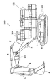
- FIG. 1 is a side view of a hydraulic shovel as an example of a construction machine according to a first embodiment of the present invention.
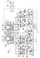
- FIG. 2 is a schematic configuration diagram of a hydraulic drive device mounted on the hydraulic excavator shown in FIG. 1.
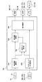
- FIG. 3 is a functional block diagram of the controller shown in FIG. 2.
- FIG. 3 is a diagram showing a behavior of the hydraulic drive device shown in FIG. 2 during a boom raising operation.
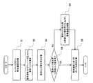
- 3 is a flowchart illustrating a process of the controller illustrated in FIG. 2. It is a figure which shows the relationship between the load torque and rotation speed of a general turbo-equipped engine.
- FIG. 3 is a diagram showing a behavior of the hydraulic drive device shown in FIG. 2 at the time of boom lowering + arm dumping operation.
- FIG. 3 is a view showing a behavior of the hydraulic drive device shown in FIG. 2 at the time of boom raising + arm dumping operation.
- FIG. 6 is a schematic configuration diagram of a hydraulic drive device according to a second embodiment of the present invention.
- 9 is a flowchart illustrating processing of a controller according to a second embodiment of the present invention. It is a figure showing the behavior at the time of boom raising + turning operation of the hydraulic drive in a 2nd example of the present invention. It is a schematic structure figure of a hydraulic drive in a 3rd example of the present invention. It is a functional block diagram of a controller in a 3rd example of the present invention.
- FIG. 1 is a side view of a hydraulic shovel according to a first embodiment of the present invention.
- a hydraulic excavator 100 includes a lower traveling body 101 equipped with a crawler-type traveling device 8, an upper revolving body 102 rotatably mounted on the lower traveling body 101 via a revolving motor 7, and an upper revolving body 102.
- a front work device 103 is attached to the front part of the body 102 so as to be rotatable up and down.
- a cab 104 on which an operator rides is provided on the upper swing body 102.
- the front working device 103 includes a boom 2 attached to a front portion of the upper swing body 102 so as to be rotatable in a vertical direction, and a working member connected to a distal end portion of the boom 2 so as to be rotatable in a vertical or front and rear direction.
- Arm 4 a bucket 6 as a working member rotatably connected to the distal end of the arm 4 in the up-down or front-rear direction, a hydraulic cylinder (hereinafter, boom cylinder) 1 for driving the boom 2, and an arm
- a hydraulic cylinder (hereinafter referred to as an arm cylinder) 3 for driving a hydraulic cylinder 4 and a hydraulic cylinder (hereinafter referred to as a bucket cylinder) 5 for driving a bucket 6 are provided.
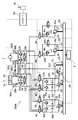
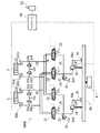
- FIG. 2 is a schematic configuration diagram of a hydraulic drive device mounted on the excavator 100 shown in FIG.
- FIG. 2 shows only parts related to driving of the boom cylinder 1 and the arm cylinder 3, and omits other parts related to driving of the actuator.
- a hydraulic drive device 300 includes a boom cylinder 1, an arm cylinder 3, a lever 51 as an operation device for instructing each operation direction and each required speed of the boom cylinder 1 and the arm cylinder 3, and A certain engine 9, a power transmission device 10 for distributing the power of the engine 9, first to fourth hydraulic pumps 12 to 15 and a charge pump 11 driven by the power distributed by the power transmission device 10, Switching valves 40 to 47 capable of switching the connection between the first to fourth hydraulic pumps 12 to 15 and the hydraulic actuators 1 and 3, proportional valves 48 and 49, switching valves 40 to 47, and proportional valves 48 and 49 , And a controller 50 for controlling regulators 12a, 13a, 14a, 15a to be described later.
- the engine 9 as a power source is connected to a power transmission device 10 for distributing power.
- the first to fourth hydraulic pumps 12 to 15 and the charge pump 11 are connected to the power transmission device 10.
- Each of the first to fourth hydraulic pumps 12 to 15 includes a tilting swash plate mechanism having a pair of input / output ports, and regulators 12a, 13a, 14a, and 15a for adjusting the tilt angle of the tilting swash plate. .
- the regulators 11a, 12a, 13a and 14a adjust the tilt angles of the tilt swash plates of the first to fourth hydraulic pumps 12 to 15 according to a signal from the controller 50.
- the first and second hydraulic pumps 12 and 13 can control the discharge flow rate and direction of hydraulic oil from the input / output port by adjusting the tilt angle of the tilt swash plate.
- the charge pump 11 replenishes the flow path 212 with pressurized oil.
- the first and second hydraulic pumps 12, 13 also function as hydraulic motors when supplied with pressure oil.
- the flow paths 200 and 201 are connected to a pair of input / output ports of the first hydraulic pump 12, and the switching valves 40 and 41 are connected to the flow paths 200 and 201.
- the switching valves 40 and 41 switch communication between the flow paths and cutoff according to a signal from the controller 50.
- the switching valves 40 and 41 are shut off when there is no signal from the controller 50.
- the switching valve 40 is connected to the boom cylinder 1 via the flow paths 210 and 211, respectively.
- the switching valve 40 is brought into a communication state by a signal from the controller 50, the first hydraulic pump 12 is connected to the boom cylinder 1 via the flow paths 200 and 201, the switching valve 40, and the flow paths 210 and 211. This constitutes a closed circuit.
- the switching valve 41 is connected to the arm cylinder 3 via the flow paths 213 and 214, respectively.
- the switching valve 41 is brought into a communication state by a signal from the controller 50, the first hydraulic pump 12 is connected to the arm cylinder 3 via the flow paths 200 and 201, the switching valve 41, and the flow paths 213 and 214. This constitutes a closed circuit.
- the flow paths 202 and 203 are connected to a pair of input / output ports of the second hydraulic pump 13, and the switching valves 42 and 43 are connected to the flow paths 202 and 203.
- the switching valves 42 and 43 switch communication and cutoff of the flow path in accordance with a signal from the controller 50. When there is no signal from the controller 50, the switching valves 42 and 43 are shut off.
- the switching valve 42 is connected to the boom cylinder 1 via the flow paths 210 and 211, respectively.
- the switching valve 42 is brought into a communication state by a signal from the controller 50, the second hydraulic pump 13 is connected to the boom cylinder 1 through the flow paths 202 and 203, the switching valve 42, and the flow paths 210 and 211. This constitutes a closed circuit.
- the switching valve 43 is connected to the arm cylinder 3 via the flow paths 213 and 214, respectively.
- the switching valve 43 is brought into a communication state by a signal from the controller 50, the second hydraulic pump 13 is connected to the arm cylinder 3 via the flow paths 202 and 203, the switching valve 43, and the flow paths 213 and 214. This constitutes a closed circuit.
- One of the pair of input / output ports of the third hydraulic pump 14 is connected to the switching valves 44 and 45, the proportional valve 48, and the relief valve 21 via the flow path 204.
- the opposite sides of the pair of input / output ports of the third hydraulic pump 14 are connected to a tank 25.
- the relief valve 21 allows the hydraulic oil to escape to the tank 25 when the flow path pressure becomes equal to or higher than a predetermined pressure, thereby protecting the circuit.
- the switching valves 44 and 45 switch communication and cutoff of the flow path in accordance with a signal from the controller 50. When there is no signal from the controller 50, the switching valves 44 and 45 are shut off.
- the switching valve 44 is connected to the boom cylinder 1 via the flow path 210.
- the switching valve 45 is connected to the arm cylinder 3 via the flow path 213.
- the proportional valve 48 changes the opening area in response to a signal from the controller 50 to control the flow rate. In the absence of a signal from the controller 50, the proportional valve 48 is held at the maximum open area. When the switching valves 44 and 45 are shut off, the controller 50 sends a signal to the proportional valve 48 so that the opening area is determined in advance according to the discharge flow rate of the third hydraulic pump 14.
- One side of the pair of input / output ports of the fourth hydraulic pump 15 is connected to the switching valves 46 and 47, the proportional valve 49, and the relief valve 22 via the flow path 205.
- the opposite side of the pair of input / output ports of the fourth hydraulic pump 15 is connected to the tank 25.
- the relief valve 22 releases the hydraulic oil to the tank 25 when the flow path pressure becomes equal to or higher than a predetermined pressure to protect the circuit.
- the switching valves 46 and 47 switch communication and cutoff of the flow path in accordance with a signal from the controller 50. When there is no signal from the controller 50, the switching valves 46 and 47 are in the shut-off state.
- the switching valve 46 is connected to the boom cylinder 1 via the flow path 210.
- the switching valve 47 is connected to the arm cylinder 3 via the flow path 213.
- the proportional valve 49 changes the opening area in response to a signal from the controller 50 to control the flow rate. When there is no signal from the controller 50, the proportional valve 49 is held at the maximum opening area. When the switching valves 46 and 47 are in the shut-off state, the controller 50 sends a signal to the proportional valve 49 so that the opening area is determined in advance according to the discharge flow rate of the fourth hydraulic pump 15.
- the discharge port of the charge pump 11 is connected to the charge relief valve 20 and the charge check valves 26, 27, 28a, 28b, 29a, 29b via the flow path 212.
- the suction port of the charge pump 11 is connected to the tank 25.
- the charging relief valve 20 adjusts the charging pressure of the charging check valves 26, 27, 28a, 28b, 29a, 29b.
- the charging check valve 26 supplies the pressure oil of the charge pump 11 to the flow paths 200 and 201 when the pressure in the flow paths 200 and 201 falls below the pressure set by the charging relief valve 20.
- the charging check valve 27 supplies the pressure oil of the charge pump 11 to the flow paths 202 and 203 when the pressure in the flow paths 202 and 203 falls below the pressure set by the charging relief valve 20.
- the charge check valves 28a and 28b supply the pressure oil of the charge pump 11 to the flow paths 210 and 211 when the pressure in the flow paths 210 and 211 falls below the pressure set by the charge relief valve 20.
- the charge check valves 29a and 29b supply the pressure oil of the charge pump 11 to the flow paths 213 and 214 when the pressure in the flow paths 213 and 214 falls below the pressure set by the charge relief valve 20.
- the relief valves 30a, 30b provided in the flow paths 200, 201 allow the hydraulic oil to escape to the tank 25 via the charging relief valve 20 when the flow path pressure exceeds a predetermined pressure, thereby protecting the circuit. I do.
- the relief valves 31a and 31b provided in the flow paths 202 and 203 allow the hydraulic oil to escape to the tank 25 via the charging relief valve 20 and protect the circuit when the flow path pressure becomes equal to or higher than a predetermined pressure. I do.
- the flow path 210 is connected to the head chamber 1 a of the boom cylinder 1.
- the flow path 211 is connected to the rod chamber 1b of the boom cylinder 1.
- the boom cylinder 1 is a hydraulic single rod cylinder that expands and contracts by receiving a supply of hydraulic oil.
- the expansion and contraction direction of the boom cylinder 1 depends on the supply direction of the hydraulic oil.
- the relief valves 32a and 32b provided in the flow paths 210 and 211 allow the hydraulic oil to escape to the tank 25 via the charging relief valve 20 and protect the circuit when the flow path pressure becomes equal to or higher than a predetermined pressure. I do.
- the flushing valve 34 provided in the flow paths 210 and 211 discharges excess oil in the flow path to the tank 25 via the charging relief valve 20.
- the flow path 213 is connected to the head chamber 3 a of the arm cylinder 3.
- the flow path 214 is connected to the rod chamber 3 b of the arm cylinder 3.
- the arm cylinder 3 is a hydraulic single rod cylinder that expands and contracts by receiving a supply of hydraulic oil.
- the direction of expansion and contraction of the arm cylinder 3 depends on the direction of supply of hydraulic oil.
- the relief valves 33a and 33b provided in the flow paths 213 and 214 allow the hydraulic oil to escape to the tank 25 via the charging relief valve 20 and protect the circuit when the flow path pressure becomes equal to or higher than a predetermined pressure. I do.
- the flushing valve 35 provided in the flow paths 210 and 211 discharges excess oil in the flow path to the tank 25 via the charging relief valve 20.
- the pressure sensor 60a connected to the flow path 210 measures the pressure in the flow path 210 and inputs the measured pressure to the controller 50.
- the pressure sensor 60a measures the head chamber pressure of the boom cylinder 1 by measuring the pressure of the flow path 210.
- the pressure sensor 60b connected to the flow path 211 measures the pressure in the flow path 211 and inputs the measured pressure to the controller 50.
- the pressure sensor 60b measures the rod chamber pressure of the boom cylinder 1 by measuring the pressure of the flow path 211.
- the pressure sensor 61a connected to the flow path 213 measures the pressure in the flow path 213 and inputs the measured pressure to the controller 50.
- the pressure sensor 61a measures the head chamber pressure of the arm cylinder 3 by measuring the pressure of the flow path 213.
- the pressure sensor 61b connected to the flow path 214 measures the pressure in the flow path 214 and inputs the measured pressure to the controller 50.
- the pressure sensor 61b measures the pressure of the rod chamber of the arm cylinder 3 by measuring the pressure of the flow path 214.
- the lever 51 inputs an operation amount of each actuator from the operator to the controller 50.
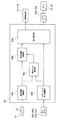
- FIG. 3 is a functional block diagram of the controller 50 shown in FIG. In FIG. 3, as in FIG. 2, only a part related to driving the boom cylinder 1 and the arm cylinder 3 is shown, and other parts related to driving the actuator are omitted.
- the controller 50 includes a required speed calculating unit 50a, an actuator pressure calculating unit 50b, a required torque estimating unit 50c, a required speed limiting unit 50d, and a command calculating unit 50e.
- the requested speed calculation unit 50a calculates the operation direction and requested speed of each actuator in response to an operator's lever input, and outputs the calculation to the requested torque estimation unit 50c and the requested speed limit unit 50d.
- the actuator pressure calculation unit 50b calculates the pressures of the actuators 1 and 3 (hereinafter, actuator pressures) from the values of the pressure sensors 60a, 60b, 61a and 61b provided in each unit, and calculates a required torque estimation unit 50c and a command calculation unit. Output to 50e.
- the required torque estimating unit 50c drives the actuators 1 and 3 based on the required speed input from the required speed calculating unit 50a and the actuator pressure input from the actuator pressure calculating unit 50b in response to an operator's lever input. Then, the torque applied to the engine 9 (hereinafter, required torque) is estimated.
- the required speed limiting unit 50d calculates a required torque change rate (hereinafter, required torque change rate) based on the required torque input from the required torque estimation unit 50c. Then, the request speed input from the request speed calculation unit 50a is limited so that the request torque change rate does not exceed an allowable torque change rate (described later) set in advance based on the characteristics of the engine 9, and the command calculation unit 50e. Output to a required torque change rate (hereinafter, required torque change rate) based on the required torque input from the required torque estimation unit 50c. Then, the request speed input from the request speed calculation unit 50a is limited so that the request torque change rate does not exceed an allowable torque change rate (described later) set in advance based on the characteristics of the engine 9, and the command calculation unit 50e. Output to
- the command calculation unit 50e is configured to control the switching valves 40 to 47, the proportional valves 48 and 49, and the regulators 12a and 13a based on the actuator pressure input from the actuator pressure calculation unit 50b and the required speed input from the required speed limit unit 50d. , 14a and 15a are calculated.
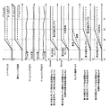
- FIG. 4 shows the input of the lever 51, the required cylinder speed based on the input of the lever 51, and the first hydraulic pump 12 when the boom cylinder 1 is extended by the hydraulic pressure driving device 300. And the sum of the required discharge flow rate of the third hydraulic pump 14 and the required discharge flow rate of the fourth hydraulic pump 15, the pressure sensors 60a and 60b. , The head chamber pressure and rod chamber pressure of the boom cylinder 1, the engine load torque, the discharge flow rate of the first hydraulic pump 12, the discharge flow rate of the second hydraulic pump 13, and the discharge rate of the third hydraulic pump 14. The change in the flow rate and the discharge flow rate of the fourth hydraulic pump 15 is shown.
- the input value of the lever 51 causes the command value for extending the boom cylinder 1 to be increased to the maximum value.
- FIG. 5 is a flowchart showing a flow of the pump load torque control of the controller 50.
- step S1 the controller 50 determines the required cylinder speed Vcyl_d from the input value Lin of the lever 51.
- step S2 the controller 50 calculates the sum Qcp_d of the required discharge flow rate of the first hydraulic pump 12 and the required discharge flow rate of the second hydraulic pump 13 from the required cylinder speed Vcyl_d, and the third hydraulic pressure.
- the sum Qop_d of the required discharge flow rate of the pump 14 and the required discharge flow rate of the fourth hydraulic pump 15 is calculated as follows, for example.
- step S2 the controller 50 controls the head chamber pressure Pcyl_h and rod chamber pressure Pcyl_r of the boom cylinder 1 measured by the pressure sensors 60a and 60b, the required discharge flow rate of the first hydraulic pump 12, and the second hydraulic pump.
- the boom cylinder 1 was driven according to the input of the lever 51 from the sum Qcp_d of the required discharge flow rates of the thirteenth and Qop_d of the required discharge flow rates of the third hydraulic pump 14 and the fourth hydraulic pump 15.
- the required torque Tp_d generated by the first to fourth hydraulic pumps 12 to 15 is calculated, for example, as follows.
- Neng is the engine speed
- Ploss is the pressure loss generated in the pipe from the cylinder to the pump
- ⁇ cp is the pump efficiency of the first hydraulic pump 12 and the second hydraulic pump 13.
- ⁇ op is the pump efficiency of the third hydraulic pump 14 and the fourth hydraulic pump 15.
- step S3 the change rate of the required torque Tp_d (the required torque change rate) is calculated.
- the required torque change rate is obtained, for example, by dividing a value obtained by subtracting the torque currently output by the engine 9 from the required torque Tp_d by the control cycle of the controller 50.
- step S4 the controller 50 proceeds to step S6 if the required torque change rate calculated in step S3 is equal to or less than the change rate of the allowable torque Tp_lim (hereinafter, the allowable torque change rate). Proceed to S5.
- the allowable torque Tp_lim is a torque that can be output by the engine 9 and can be calculated from information such as the fuel injection amount of the engine 9 and the turbo pressure.
- the allowable torque Tp_lim and the allowable torque change rate may be obtained as follows.
- the maximum torque change rate at which the decrease in the engine speed is suppressed to the allowable minimum speed is set as the allowable torque change rate, and the maximum output torque that satisfies the allowable torque change rate is set as the allowable torque Tp_lim.
- the allowable torque Tp_lim it is obtained by adding the product of the allowable torque change rate and the control cycle of the controller 50 to the current engine output torque. That is, the allowable torque Tp_lim in the present invention changes every moment according to the current engine output torque.
- step S4 it is determined whether the required torque change rate is equal to or less than the allowable torque change rate. This determination is the same as the determination as to whether the required torque Tp_d is equal to or less than the allowable torque Tp_lim. is there.
- step S5 the controller 50 limits the required cylinder speed Vcyl_d so that the required torque change rate is equal to or less than the allowable torque change rate (that is, the required torque Tp_d is equal to or less than the allowable torque Tp_lim).
- the engine 9 can output only the allowable torque Tp_lim with respect to the required torque Tp_d obtained in step S2, the sum Tcp_d of the required torque of the first hydraulic pump 12 and the required torque of the second hydraulic pump 13, and The sum Top_d of the required torque of the third hydraulic pump 14 and the required torque of the fourth hydraulic pump 15 is
- step S6 the controller 50 determines, based on the required cylinder speed Vcyl_d, the required discharge flow rate Qcp1_d of the first hydraulic pump 12, the required discharge flow rate Qcp2_d of the second hydraulic pump 13, and the request of the third hydraulic pump 14.
- the discharge flow rate Qop1_d and the required discharge flow rate Qop2_d of the fourth hydraulic pump 15 are calculated.
- the controller 50 calculates the sum of the required discharge flow rate of the first hydraulic pump 12 and the required discharge flow rate of the second hydraulic pump 13 from the required cylinder speed Vcyl_d using equations (2) and (4).
- Qcp_d is calculated, and the sum Qop_d of the required discharge flow rate of the third hydraulic pump 14 and the required discharge flow rate of the fourth hydraulic pump 15 is calculated using equations (3) and (5).
- the controller 50 calculates the required torque from the calculated required discharge flow rate and the head chamber pressure and the rod chamber pressure of the boom cylinder 1 measured by the pressure sensors 60a and 60b, using equations (8), (9), and (10). Calculate Tp_d.
- the required torque Tp_d increases to the maximum value from time t1 to time t2, while the allowable torque Tp_lim of the engine 9 becomes the rated maximum torque of the engine 9 from time t1 to time t3.
- the controller 50 calculates the restricted cylinder speed Vcyl_d 'using Expression (15) such that the required torque Tp_d is equal to or less than the allowable torque Tp_lim of the engine 9.
- the controller 50 determines the discharge flow rate Qcp12 of the first hydraulic pump 12, the discharge flow rate Qcp13 of the second hydraulic pump 13, the required discharge flow rate Qop14 of the third hydraulic pump 14, And the required discharge flow rate Qop15 of the fourth hydraulic pump 15 is calculated.
- the excavator 100 can be operated without causing the engine 9 to lag down.
- the horsepower is calculated based on the actuator pressure
- the engine speed is stabilized and the pressure fluctuation is equal to or less than a specified value.
- the fluctuation of the actuator pressure may be suppressed by a filtering process such as a moving average.
- the pumps are started one by one, but they may be started at the same time.
- FIG. 7 shows the input of the lever 51 and the input of the lever 51 when the hydraulic drive device 300 simultaneously performs the contraction operation of the boom cylinder 1 and the contraction operation of the arm cylinder 3.
- Required discharge flow rates of the hydraulic pumps 12 and 13 required flow rates of the proportional valves 48 and 49, engine load torque, respective discharge flow rates of the first and second hydraulic pumps 12 and 13, and the proportional valves 48 and 49. The change of each passing flow rate is shown.
- the controller 50 allocates the first hydraulic pump 12 for driving the boom cylinder 1 and allocates the second hydraulic pump 13 for driving the arm cylinder 3.
- the controller 50 calculates the required discharge flow rate Qcp12_d of the first hydraulic pump 12 from the required boom cylinder speed Vcyl_boom_d using the equations (2) and (4). Further, the controller 50 calculates the required discharge flow rate Qcp13_d of the second hydraulic pump 13 from the required arm cylinder speed Vcyl_arm_d by using equations (2) and (4).
- the controller 50 allocates the proportional valve 48 for discharging the surplus flow rate of the boom cylinder 1 and the proportional valve 49 for discharging the surplus flow rate of the arm cylinder 3.
- the controller 50 calculates the required passage flow rate Qpv48_d of the proportional valve 48 from the required boom cylinder speed Vcyl_boom_d using equations (3) and (16). Further, the controller 50 calculates the required passage flow rate Qpv49_d of the proportional valve 49 from the required arm cylinder speed Vcyl_arm_d by using equations (3) and (16).
- the controller 50 calculates the calculated required flow rate, the head chamber pressure and the rod chamber pressure of the boom cylinder 1 measured by the pressure sensors 60a and 60b, and the head chamber pressure and the rod chamber pressure of the arm cylinder 3 measured by the pressure sensors 61a and 61b.
- the required torque Tp_d is calculated by using equations (8) and (10).
- the discharge pressure of the first hydraulic pump 12 becomes higher than the suction pressure when raising the boom to extend the boom cylinder 1.
- the first hydraulic pump 12 operates as a pump.
- the suction pressure of the first hydraulic pump 12 becomes higher than the discharge pressure, so that the first hydraulic pump 12 operates as a motor.
- the discharge pressure of the second hydraulic pump 13 becomes higher than the suction pressure during arm dump when the arm cylinder 3 contracts.
- the second hydraulic pump 13 operates as a pump.
- the suction pressure of the second hydraulic pump 13 becomes higher than the discharge pressure, so that the second hydraulic pump 13 operates as a motor.
- the first hydraulic pump 12 when the input of the lever 51 is lowered and the arm is dumped, the first hydraulic pump 12 operates as a motor and the second hydraulic pump 13 operates as a pump.
- the sum of the required torque and the required torque of the second hydraulic pump 13, Tcp_d, is lower than when the first hydraulic pump 12 and the second hydraulic pump 13 both operate as pumps alone.
- the excavator 100 can be operated without causing the engine 9 to lag down.
- the vibration of the actuator pressure may be suppressed by a filtering process such as a moving average.
- FIG. 8 shows the input of the lever 51 and the input of the lever 51 when the extension operation of the boom cylinder 1 and the contraction operation of the arm cylinder 3 are simultaneously performed by the hydraulic pressure driving device 300.
- the input value of the lever 51 increases the command value for extending the boom cylinder 1 and the command value for contracting the arm cylinder 3 to the maximum value.
- the controller 50 controls the first hydraulic pump 12 and the third hydraulic pump 14 for driving the boom cylinder 1 and the second hydraulic pump 13 and the proportional valve 49 for driving the arm cylinder 3. assign.
- the controller 50 calculates the required discharge flow rate Qcp12_d of the first hydraulic pump 12 from the required boom cylinder speed Vcyl_boom_d using the equations (2) and (4). Further, the controller 50 calculates the required discharge flow rate Qcp13_d of the second hydraulic pump 13 from the required arm cylinder speed Vcyl_arm_d by using equations (2) and (4).
- the controller 50 calculates the required discharge flow rate Qop14_d of the third hydraulic pump 14 from the required boom cylinder speed Vcyl_boom_d using the equations (3) and (5).
- the controller 50 calculates the required passage flow rate Qpv49_d of the proportional valve 49 from the required arm cylinder speed Vcyl_arm_d by using equations (3) and (16).
- the controller 50 calculates the calculated required flow rate, the head chamber pressure and the rod chamber pressure of the boom cylinder 1 measured by the pressure sensors 60a and 60b, and the head chamber pressure and the rod chamber pressure of the arm cylinder 3 measured by the pressure sensors 61a and 61b.
- the required torque Tcp12_d of the first hydraulic pump 12 the required torque Tcp13_d of the second hydraulic pump 13, and the required torque Top14_d of the third hydraulic pump 14 are calculated. I do. At this time, the required torque Tp_d is
- the controller 50 calculates the discharge flow rate Qcp12 of the first hydraulic pump 12 and the required discharge flow rate Qop14 of the third hydraulic pump 14 based on the restricted boom cylinder velocity Vcyl_boom_d ', and calculates the restricted arm cylinder velocity Vcyl_arm_d'. Based on this, the discharge flow rate Qcp13 of the second hydraulic pump 13 and the flow rate Qpv49 of the proportional valve 49 are calculated.
- the engine 9, variable displacement hydraulic pumps 12 to 15 driven by the engine 9, and hydraulic actuators 1 and 3 driven by hydraulic fluid discharged from the hydraulic pumps 12 to 15 Control valves 40 to 47 capable of switching the connection between the hydraulic actuators 1 and 3 and the hydraulic pumps 12 to 15, and pressure detecting devices 60a, 60b and 61a for detecting each load pressure of the hydraulic actuators 1 and 3. 61b, an operation device 51 for instructing each operation direction and each required speed of the hydraulic actuators 1 and 3, and a controller 50 for controlling each discharge flow rate of the hydraulic pumps 12 to 15 according to an input from the operation device 51.
- a required torque estimating unit 50c for estimating a required torque Tp_d which is the sum of the torques required in the case where the required torque change rate, which is a change rate of the required torque Tp_d, exceeds a predetermined change rate (allowable torque change rate).
- a request speed limiter 50d that limits each required speed of the hydraulic actuators 1 and 3 so that the required torque change rate is equal to or less than the predetermined change rate; and a required torque change rate that is a change rate of the required torque.
- a required speed limiting unit 50d for limiting each required speed of the hydraulic actuators 1 and 3 so that the required torque change rate is equal to or less than the predetermined rate of change when the predetermined rate of change is exceeded;
- the assignment of the hydraulic pumps 12 to 15 to the hydraulic actuators 1 and 3 is determined based on the required speeds of the hydraulic actuators 1 and 3 limited by the section 50d.
- a command calculation unit 50e for calculating each discharge flow rate of the pumps 12 to 15.
- Each of the hydraulic pumps 12 and 13 is a double-discharge hydraulic pump having a pair of input / output ports, and the control valves 40 to 43 are connected to the hydraulic pumps 12 and 13 and the hydraulic actuators 1 and 3, respectively. This is a switching valve that can switch the connection of.
- the hydraulic drive device 300 that controls the flow of the hydraulic oil supplied from the two-discharge type hydraulic pumps 12 and 13 to the actuators 1 and 3 by the switching valves 40 to 43.
- the required torque Tp_d for the engine 9 is estimated based on the required speed of the hydraulic actuators 1 and 3 and the load pressure of the hydraulic actuators 1 and 3, and the required torque change rate becomes a predetermined change rate ( When the allowable torque change rate exceeds the allowable torque change rate, the required speed of the hydraulic actuators 1 and 3 is limited so that the required torque change rate is equal to or less than a predetermined change rate. This makes it possible to suppress a lag-down of the engine 9 irrespective of the operation contents of the operator and the load state of the hydraulic actuators 1 and 3.
- the command calculation unit 50e determines that the required torque change rate is a predetermined change rate (allowable torque change rate) in a state where two or more hydraulic pumps are assigned to one of the hydraulic actuators 1 and 3. ), The number of hydraulic pumps allocated to the one hydraulic actuator is reduced according to the required speed of the one hydraulic actuator limited by the required speed limiting unit 50d. This improves the fuel efficiency of the hydraulic pump in use and increases the number of unused hydraulic pumps, thereby facilitating assignment of the hydraulic pump to a newly operated actuator.
- a predetermined change rate allowable torque change rate
- the required cylinder speed Vcyl_d is uniquely determined from the input of the lever 51 by Expression (1).
- the required cylinder speed Vcyl_d is determined by the load state of each actuator and the balance of the input value of the lever 51. May be provided in the controller 50.
- the hydraulic excavator 100 according to the second embodiment of the present invention will be described focusing on the differences from the first embodiment.
- FIG. 9 is a schematic configuration diagram of the hydraulic drive device in the present embodiment.
- the difference from the first embodiment (shown in FIG. 2) is that the arm cylinder 3 is replaced by a swing motor 7.
- the flow path 215 is connected to the port a of the turning motor 7.
- the flow path 216 is connected to the b port of the turning motor 7.
- the turning motor 7 is a hydraulic motor that rotates by receiving a supply of hydraulic oil.
- the rotation direction of the swing motor 7 depends on the supply direction of the working oil.
- the relief valves 37a and 37b provided in the flow passages 215 and 216 allow the hydraulic oil to escape to the tank 25 via the charging relief valve 20 and protect the circuit when the flow passage pressure becomes equal to or higher than a predetermined pressure. I do.
- the flushing valve 38 provided in the flow passages 215 and 216 discharges excess oil in the flow passage to the tank 25 via the charging relief valve 20.
- the pressure sensor 62 a connected to the flow path 215 measures the pressure in the flow path 215 and inputs the measured pressure to the controller 50.
- the pressure sensor 62a measures the pressure in the flow path 215 to measure the a-port pressure Pswing_a of the swing motor 7.
- the pressure sensor 62b connected to the flow path 216 measures the pressure in the flow path 216 and inputs the measured pressure to the controller 50.
- the pressure sensor 62b measures the b-port pressure Pswing_b of the swing motor 7 by measuring the pressure in the flow path 216.
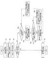
- FIG. 10 is a flowchart showing a flow of the pump load torque control of the controller 50 shown in FIG. 10 differs from the first embodiment (shown in FIG. 5) in that steps S5a to S5f are provided instead of step S5.
- steps S5a to S5f are provided instead of step S5.
- step S5a the controller 50 proceeds to step S5b if the combined operation of the boom and the turn is performed, and proceeds to step S5f otherwise.
- step S5b the controller 50 limits the required speed of the swing motor 7 so that the required torque of the swing motor 7 is equal to or less than a predetermined ratio of the total allowable torque Tp_lim.
- step S5c the controller 50 proceeds to step S5d if the sum of the required torque of the swing motor 7 having the limited required speed and the required torque of the actuators other than the other swing motors 7 exceeds the total allowable torque Tp_lim, and otherwise proceeds to step S5d. In this case, the process proceeds to step S5e.
- step S5d the controller 50 determines a required speed of an actuator other than the swing motor 7 from the input value Lin of the lever 51.
- step S5e the controller 50 limits the required speeds of the actuators other than the swing motor 7 so that the total required torque of each actuator is equal to or less than the total allowable torque Tp_lim while maintaining the required speed ratio of each actuator.
- step S5f the controller 50 limits the required speed of each actuator so that the total required torque of each actuator is equal to or less than the total allowable torque Tp_lim while maintaining the required speed ratio of each actuator.
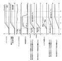
- FIG. 11 is based on the input of the lever 51 and the input of the lever 51 when the extension operation of the boom cylinder 1 and the turning operation of the swing motor 7 are simultaneously performed by the hydraulic pressure driving device 300.
- the change of each required discharge flow rate of the third to third hydraulic pumps 12 to 14, the engine load torque, and the change of each discharge flow rate of the first to third hydraulic pumps 12 to 14 are shown.
- the input value of the lever 51 increases the command value for extending the boom cylinder 1 and the command value for rotating the swing motor 7 to the maximum value.
- the controller 50 allocates the first hydraulic pump 12 and the third hydraulic pump 14 for driving the boom cylinder 1 and the second hydraulic pump 13 for driving the swing motor 7.
- the controller 50 calculates the required discharge flow rate Qcp12_d of the first hydraulic pump 12 from the required boom cylinder speed Vcyl_boom_d using the equations (2) and (4).
- the required discharge flow rate Qcp13_d of the second hydraulic pump 13 is calculated using the equations (25) and (26).
- the controller 50 calculates the required discharge flow rate Qop14_d of the third hydraulic pump 14 from the required boom cylinder speed Vcyl_boom_d using the equations (3) and (5).
- the controller 50 calculates the required flow rate, the head chamber pressure and the rod chamber pressure of the boom cylinder 1 measured by the pressure sensors 60a and 60b, and the a port pressure Pswing_a and the b port pressure of the swing motor 7 measured by the pressure sensors 62a and 62b. From Pswing_a, using equations (8) and (9), the required torque Tcp12_d of the first hydraulic pump 12, the required torque Tcp13_d of the second hydraulic pump 13, and the required torque of the third hydraulic pump 14 Calculate Top14_d. At this time, the required torque Tp_d is
- the required torque Tp_d increases to the maximum value from the time t1 to the time t2, while the allowable torque Tp_lim of the engine 9 becomes the rated maximum torque of the engine 9 from the time t1 to the time t3.
- the controller 50 from time t1 to time t3, the controller 50
- a characteristic is that the port a pressure and the port b pressure are low during stoppage, and the pressure at one port increases during turning acceleration. is there.
- the port pressure on one side rises to the set pressure of the relief valves 37a and 37b. Therefore, when a required speed exceeding the maximum acceleration is input, if a required flow rate is supplied from the pump, a part of the flow rate is discharged from one of the relief valves 37a and 37b to the tank 25 and is wasted.
- the ratio of the horsepower assigned to the swing motor 7 is set lower than the ratio of the horsepower assigned to the boom cylinder 1. That is, 50% or less (for example, 20%) of the horsepower that can be output by the engine 9 is allocated to the turning motor 7. From equation (28),
- the controller 50 calculates the discharge flow rate Qcp12 of the first hydraulic pump 12 and the required discharge flow rate Qop14 of the third hydraulic pump 14 based on the limited boom cylinder speed Vcyl_boom_d ', and based on the limited swing speed Wswing_d'. , The discharge flow rate Qcp13 of the second hydraulic pump 13 is calculated.
- the hydraulic actuators 1 and 7 include one or more hydraulic cylinders 1 and one or more hydraulic motors 7, and the command calculation unit 50e includes the hydraulic cylinder 1 and the hydraulic motor 7
- the required torque change rate exceeds a predetermined change rate (permissible torque change rate) in a state where the motors are simultaneously driven, the required torque of the hydraulic pump assigned to the hydraulic motor 7 is changed to the output torque of the engine 9.
- the respective discharge flow rates of the hydraulic pumps 12 to 15 are calculated so as to be equal to or less than a predetermined ratio (for example, 20%).
- the engine 9 is lagged down while the speed of the boom cylinder 1 is not significantly reduced due to the pressure increase of the swing motor 7 at the start of swing.
- the excavator 100 can be operated without the need for this.
- FIG. 12 is a schematic configuration diagram of the hydraulic drive device in the present embodiment
- FIG. 13 is a functional block diagram of the controller 50 in the present embodiment. 12 and 13, the difference from the first embodiment (shown in FIGS. 2 and 3) is that the components of the closed circuit are eliminated, and that the hydraulic pumps 13 and 14 and the hydraulic actuators 1 and 2 are different. 3 in that the switching valves 44 to 47 capable of switching the connection with the third valve 3 are replaced with flow control valves 71 to 74.
- the flow control valve 71 is connected to the flow path 204, the tank 25, the flow path 210, and the flow path 211.
- the flow control valve 72 connects the flow path 204 and the tank 25 and closes a port connected to the flow path 210 and the flow path 211.
- the flow control valve 71 connects the flow path 204 and the flow path 210, and connects the tank 25 and the flow path 211.
- the flow control valve 71 connects the flow path 204 to the flow path 211 and connects the tank 25 to the flow path 210.
- the opening area of the flow path connecting each flow path changes according to the magnitude of the positive or negative signal.
- the flow control valve 72 is connected to the flow path 204, the tank 25, the flow path 213, and the flow path 214. When there is no signal at the flow control valve 72, the flow control valve 72 connects the flow path 204 and the tank 25, and closes the ports connected to the flow paths 213 and 214. When a positive signal is input to the flow control valve 72, the flow control valve 72 connects the flow path 204 and the flow path 213, and connects the tank 25 and the flow path 214. When a negative signal is input, the flow control valve 71 connects the flow path 204 to the flow path 214 and connects the tank 25 to the flow path 213. The opening area of the flow path connecting each flow path changes according to the magnitude of the positive or negative signal.
- the flow control valve 73 is connected to the flow path 205, the tank 25, the flow path 210, and the flow path 211.
- the flow control valve 73 connects the flow path 205 to the tank 25 and closes a port connected to the flow path 210 and the flow path 211.
- the flow control valve 73 connects the flow path 205 to the flow path 210 and connects the tank 25 to the flow path 211.
- a negative signal is input, the flow control valve 73 connects the flow path 205 to the flow path 211 and connects the tank 25 to the flow path 210.
- the opening area of the flow path connecting each flow path changes according to the magnitude of the positive or negative signal.
- the flow control valve 74 is connected to the flow path 205, the tank 25, the flow path 213, and the flow path 214.
- the flow control valve 72 connects the flow path 205 and the tank 25, and closes the ports connected to the flow paths 213 and 214.
- the flow control valve 74 connects the flow path 205 and the flow path 213, and connects the tank 25 and the flow path 214.
- the flow control valve 74 connects the flow path 205 to the flow path 214 and connects the tank 25 to the flow path 213.
- the opening area of the flow path connecting each flow path changes according to the magnitude of the positive or negative signal.
- the demands of the actuators determined by the input of the lever 51 can be determined in the same manner as in the first embodiment. It is possible to operate the excavator 100 without lagging down the engine 9 while maintaining the speed ratio. If the flow control valves 71 to 74 are used with the maximum opening area and the speeds of the boom cylinder 1 and the arm cylinder 3 are controlled by the discharge flow rates of the hydraulic pumps 14 and 15, the flow control valves 71 to 74 are generated. The resulting pressure loss is easier to estimate.
- the hydraulic excavator 100 includes hydraulic pumps 13 and 14, hydraulic actuators 1 and 3, and control valves 71 to which connection between the hydraulic actuators 1 and 3 and the hydraulic pumps 13 and 14 can be switched.
- the pressure detecting devices 60a, 60b, 61a, 61b can detect the respective load pressures of the hydraulic actuators 1, 3, and the operating device 51 can control the operating directions and the operating directions of the hydraulic actuators 1, 3 respectively.
- the required speed can be instructed, and the required torque estimating unit 50c calculates the sum of the torques required by the hydraulic pumps 13 and 14 for the engine 9 based on the required speeds and the load pressures of the hydraulic actuators 1 and 3.
- the required speed limiting unit 50d determines that the required torque change rate, which is the rate of change of the required torque, exceeds a predetermined rate of change (permissible torque change rate).
- the required speeds of the hydraulic actuators 1 and 3 are limited so that the rate of change becomes equal to or less than the predetermined change rate.
- the assignment of the hydraulic pumps 13 and 14 to the hydraulic actuators 1 and 3 is determined based on the required speed, and the respective discharge flow rates of the hydraulic pumps 13 and 14 are calculated.
- the hydraulic pumps 14 and 15 are single-discharge hydraulic pumps each having a suction port and a discharge port, and can switch the connection between the hydraulic actuators 1 and 3 and the hydraulic pumps 14 and 15.
- the control valves 71 to 74 are flow rate control valves capable of adjusting the direction and flow rate of the hydraulic fluid supplied from the hydraulic pumps 14 and 15 to the hydraulic actuators 1 and 3.
- the hydraulic drive 300B equipped with the hydraulic drive device 300B capable of switching the connection between the hydraulic actuators 1, 3 and the hydraulic pumps 13, 14 by the flow control valves 71 to 74 is mounted.
- the shovel 100 as in the first embodiment, it is possible to suppress the engine 9 from lagging down regardless of the operation content of the operator and the load state of the actuators 1 and 3.
- the present invention is not limited to the above-described embodiments, and includes various modifications.
- the above-described embodiments have been described in detail for easy understanding of the present invention, and are not necessarily limited to those having all the configurations described above. It is also possible to add a part of the configuration of another embodiment to the configuration of a certain embodiment, delete a part of the configuration of one embodiment, or replace it with a part of another embodiment. It is possible.
- Power Transmission device 11: charge pump, 12: first hydraulic pump, 12a: regulator, 13: second hydraulic pump, 13a: regulator, 14: third hydraulic pump, 14a: regulator, 15: first 4 hydraulic pump, 15a regulator, 20 relief valve for charging, 21, 22 relief valve, 25 tank, 26, 27, 28a, 2 b, 29a, 29b ... charge check valve, 30a, 30b, 31a, 31b, 32a, 32b, 33a, 33b ... relief valve, 34, 35 ... flushing valve, 36a, 36b ... charge check valve, 37a, 37b ...
- Relief valve, 38 Flushing valve, 40 to 47: Switching valve (control valve), 48, 49: Proportional valve, 50: Controller, 50a: Requested speed calculator, 50b: Actuator pressure calculator, 50c: Requested torque estimator , 50d: required speed limiter, 50e: command calculator, 51: lever (operating device), 60a, 60b, 61a, 61b, 62a, 62b: pressure sensor (pressure detecting device), 71 to 74: flow control valve ( Control valve), 100: hydraulic excavator, 101: lower traveling structure, 102: upper revolving structure, 103: front working device, 104: Catcher Bed, 200-216 ... passage, 300, 300A, 300B ... hydraulic drive.
Landscapes
- Engineering & Computer Science (AREA)
- General Engineering & Computer Science (AREA)
- Mining & Mineral Resources (AREA)
- Civil Engineering (AREA)
- Structural Engineering (AREA)
- Physics & Mathematics (AREA)
- Fluid Mechanics (AREA)
- Mechanical Engineering (AREA)
- Chemical & Material Sciences (AREA)
- Analytical Chemistry (AREA)
- Operation Control Of Excavators (AREA)
- Fluid-Pressure Circuits (AREA)
Abstract
The present invention addresses the problem of providing a construction machine capable of suppressing engine lug-down regardless of the content of an operation by an operator or the load state of a hydraulic actuator. A controller 50 has: a requested torque estimation unit 50c which, on the basis of a requested speed of a first hydraulic actuator 1 and a load pressure of the first hydraulic actuator, estimates a requested torque, which is the torque requested from an engine 9 by a first hydraulic pump; a requested speed limiting unit 50d which, when a requested torque change rate, which is the rate of change of the requested torque, exceeds a prescribed change rate, limits the requested speed such that the requested torque change rate is no greater than the prescribed change rate; and a command calculation unit 50e which calculates a discharge flow rate of the first hydraulic pump on the basis of the requested speed of the first hydraulic actuator that has been limited by the requested speed limiting unit.
Description
本発明は、エンジンで駆動される液圧ポンプで液圧アクチュエータに圧液を供給する液圧駆動装置が搭載された建設機械に関する。
The present invention relates to a construction machine equipped with a hydraulic drive device for supplying hydraulic fluid to a hydraulic actuator by a hydraulic pump driven by an engine.
近年、油圧ショベルなどの建設機械において、油圧シリンダなどの油圧アクチュエータを駆動させる油圧回路内の絞り要素を減らし燃料消費率を低減するために、油圧ポンプから作動油を油圧アクチュエータへ送り、油圧アクチュエータで仕事を行った作動油をタンクに戻さず油圧ポンプへ戻すように接続した油圧回路(以下、油圧閉回路)の開発が進められている。
In recent years, in construction machines such as hydraulic excavators, hydraulic oil is sent from hydraulic pumps to hydraulic actuators to reduce the throttle element in the hydraulic circuit that drives hydraulic actuators such as hydraulic cylinders and reduce the fuel consumption rate. The development of a hydraulic circuit (hereinafter referred to as a hydraulic closed circuit) connected to return a working hydraulic oil to a hydraulic pump without returning it to a tank is in progress.
エンジンを原動力として油圧ポンプを駆動する場合、エンジンの出力を効果的に使用しつつ、過負荷でエンジンが停止しないようにエンジンにかかる負荷馬力を制御する必要がある。油圧ポンプの馬力制御に関する先行技術を開示するものとして、例えば特許文献1がある。
場合 When driving a hydraulic pump using an engine as a driving force, it is necessary to control the load horsepower applied to the engine so that the engine does not stop due to overload while effectively using the output of the engine. Patent Document 1 discloses, for example, a prior art relating to horsepower control of a hydraulic pump.
特許文献1には、エンジンにより駆動される可変容量式の油圧ポンプと、前記油圧ポンプから作動油が供給される複数のアクチュエータとを有する作業機械に設けられる制御装置であって、前記各アクチュエータに対する作動指令を入力するために操作を受ける入力部(操作レバー)と、前記各アクチュエータのうち操作対象となるアクチュエータとこのアクチュエータについてなされる操作の方向とによって特定される操作内容ごとに、その操作量と前記油圧ポンプの吸収馬力の上限値とを関連付けた馬力情報を記憶する記憶部と、前記入力部によって少なくとも一つのアクチュエータに対する作動指令が入力された場合に、前記記憶部に記憶された馬力情報を用いて各アクチュエータ毎に前記吸収馬力の上限値を決定する操作馬力決定部と、前記操作馬力決定部により決定された吸収馬力の上限値のうち最も大きな吸収馬力の上限値を選択する高位選択部と、前記高位選択部により選択された吸収馬力以下の馬力となるように前記油圧ポンプの容量を調整する容量調整部とを備え、前記記憶部に記憶された馬力情報のうち、少なくとも一つの操作内容に係る馬力情報は、前記入力部の操作量の変化に応じて吸収馬力の上限値が変化する特性を有することを特徴とする作業機械の制御装置が記載されている。
Patent Document 1 discloses a control device provided in a work machine including a variable displacement hydraulic pump driven by an engine and a plurality of actuators to which hydraulic oil is supplied from the hydraulic pump. For each operation content specified by an input unit (operating lever) that receives an operation for inputting an operation command, an actuator to be operated among the actuators, and a direction of an operation performed on the actuator, an operation amount thereof And a horsepower information storing the horsepower information in which the hydraulic horsepower absorption upper limit value of the hydraulic pump is associated with the horsepower information stored in the memory unit when an operation command for at least one actuator is input by the input unit. Operating horsepower determination for determining the upper limit of the absorption horsepower for each actuator using A high-order selection unit that selects the largest absorption horsepower upper limit value among the absorption horsepower upper limit values determined by the operation horsepower determination unit, and a horsepower that is equal to or less than the absorption horsepower selected by the high-order selection unit. A capacity adjusting unit that adjusts the capacity of the hydraulic pump, wherein the horsepower information related to at least one operation content among the horsepower information stored in the storage unit is absorbed in accordance with a change in the operation amount of the input unit. A control device for a work machine is described, which has a characteristic that the upper limit value of the horsepower changes.
特許文献1に記載の作業機械の制御装置によれば、操作レバーの操作量及び操作方向に応じて油圧ポンプの吸収馬力の上限値が設定することにより、エンジンの負荷を抑えてエンスト等の不具合を抑制することができる。しかし、操作レバーの操作速度やアクチュエータの負荷状態を考慮していないため、例えば以下のような課題が生じる。
According to the control device for a work machine described in Patent Document 1, the upper limit of the absorption horsepower of the hydraulic pump is set in accordance with the operation amount and operation direction of the operation lever, thereby suppressing the engine load and causing a malfunction such as engine stall. Can be suppressed. However, since the operation speed of the operation lever and the load state of the actuator are not taken into consideration, for example, the following problem occurs.
オペレータが操作レバーを高速で操作すると、操作対象となるアクチュエータに接続されている油圧ポンプの吐出流量が急速に増加し、当該アクチュエータの負荷圧に応じて当該油圧ポンプがエンジンに要求するトルク(要求トルク)が急激に上昇する。このとき、要求トルクの上昇に対してエンジン出力トルクの上昇が間に合わず、要求トルクの絶対値がエンジンの最大定格トルクを下回っている場合であっても、エンジン回転数が停止または一時的に低下する現象(ラグダウン)が発生するおそれがある。特に、油圧ポンプでアクチュエータを直接に駆動する油圧閉回路では、アクチュエータと油圧ポンプとの間に絞り要素が介在せず、アクチュエータの負荷が油圧ポンプに直接的に伝わるため、この傾向が顕著となる。
When the operator operates the operation lever at high speed, the discharge flow rate of the hydraulic pump connected to the actuator to be operated rapidly increases, and the torque (requested torque) required by the hydraulic pump to the engine according to the load pressure of the actuator is increased. Torque) rises sharply. At this time, even if the increase in the engine output torque cannot keep up with the increase in the required torque, and the absolute value of the required torque is lower than the maximum rated torque of the engine, the engine speed stops or temporarily decreases. Phenomenon (lag down) may occur. In particular, in a hydraulic closed circuit in which an actuator is directly driven by a hydraulic pump, a throttle element is not interposed between the actuator and the hydraulic pump, and the load of the actuator is directly transmitted to the hydraulic pump. .
本発明は、上記の課題に鑑みてなされたものであり、その目的は、オペレータの操作内容やアクチュエータの負荷状態にかかわらず、エンジンのラグダウンを抑制できる建設機械を提供することにある。
The present invention has been made in view of the above problems, and an object of the present invention is to provide a construction machine that can suppress engine lag down regardless of the operation contents of an operator and the load state of an actuator.
上記目的を達成するために、本発明は、エンジンと、前記エンジンによって駆動される可変容量型の第1液圧ポンプと、前記第1液圧ポンプから吐出された圧液によって駆動される第1液圧アクチュエータと、前記第1液圧アクチュエータの動作方向および要求速度を指示する第1操作装置と、前記操作装置からの入力に応じて前記第1液圧ポンプの吐出流量を制御するコントローラとを備えた建設機械において、前記第1液圧アクチュエータの負荷圧を検出する第1圧力検出装置を備え、前記コントローラは、前記第1液圧アクチュエータの要求速度と前記第1液圧アクチュエータの負荷圧とに基づき、前記第1液圧ポンプが前記エンジンに要求するトルクである要求トルクを推定する要求トルク推定部と、前記要求トルクの変化率である要求トルク変化率が所定の変化率を上回った場合に、前記要求トルク変化率が前記所定の変化率以下になるように前記要求速度を制限する要求速度制限部と、前記要求速度制限部によって制限された前記第1液圧アクチュエータの要求速度に基づき、前記第1液圧ポンプの吐出流量を演算する指令演算部とを有するものとする。
In order to achieve the above object, the present invention provides an engine, a variable displacement first hydraulic pump driven by the engine, and a first hydraulic pump driven by the hydraulic fluid discharged from the first hydraulic pump. A hydraulic actuator, a first operating device for instructing an operation direction and a required speed of the first hydraulic actuator, and a controller for controlling a discharge flow rate of the first hydraulic pump in accordance with an input from the operating device. A construction machine provided with a first pressure detecting device for detecting a load pressure of the first hydraulic actuator, wherein the controller determines a required speed of the first hydraulic actuator, a load pressure of the first hydraulic actuator, A required torque estimating unit for estimating a required torque, which is a torque required by the first hydraulic pump to the engine, based on A request speed limiting unit that limits the required speed so that the required torque change rate is equal to or less than the predetermined change rate when the required torque change rate exceeds a predetermined rate; And a command calculator for calculating the discharge flow rate of the first hydraulic pump based on the required speed of the first hydraulic actuator.
以上のように構成した本発明によれば、第1液圧アクチュエータの要求速度および第1液圧アクチュエータの負荷圧に基づいてエンジンに対する要求トルクが推定され、要求トルク変化率が所定の変化率を上回った場合に、要求トルク変化率が所定の変化率以下になるように第1液圧アクチュエータの要求速度が制限される。これにより、オペレータの操作内容や液圧アクチュエータの負荷状態にかかわらず、エンジンのラグダウンを抑制することが可能となる。
According to the present invention configured as described above, the required torque for the engine is estimated based on the required speed of the first hydraulic actuator and the load pressure of the first hydraulic actuator, and the required torque change rate becomes a predetermined change rate. If it exceeds, the required speed of the first hydraulic actuator is limited so that the required torque change rate is equal to or less than a predetermined change rate. This makes it possible to suppress the engine lag down regardless of the operation contents of the operator and the load state of the hydraulic actuator.
本発明によれば、エンジンで駆動される液圧ポンプで液圧アクチュエータに圧液を供給する液圧駆動装置が搭載された建設機械において、オペレータの操作内容やアクチュエータの負荷状態にかかわらず、エンジンのラグダウンを抑制することができる。
According to the present invention, in a construction machine equipped with a hydraulic drive device that supplies hydraulic fluid to a hydraulic actuator with a hydraulic pump driven by the engine, the engine is operated irrespective of the operation content of the operator and the load state of the actuator. Lag can be suppressed.
以下、本発明の実施の形態に係る建設機械として油圧ショベルを例に挙げ、図面を参照して説明する。なお、各図中、同等の部材には同一の符号を付し、重複した説明は適宜省略する。
Hereinafter, a hydraulic excavator will be described as an example of a construction machine according to an embodiment of the present invention with reference to the drawings. In each of the drawings, the same members are denoted by the same reference numerals, and duplicate description will be omitted as appropriate.
図1は、本発明の第1の実施例に係る油圧ショベルの側面図である。
FIG. 1 is a side view of a hydraulic shovel according to a first embodiment of the present invention.
図1において、油圧ショベル100は、クローラ式の走行装置8を装備した下部走行体101と、下部走行体101上に旋回モータ7を介して旋回可能に取り付けられた上部旋回体102と、上部旋回体102の前部に上下方向に回動可能に取り付けられたフロント作業装置103とを備えている。上部旋回体102上には、オペレータが搭乗するキャブ104が設けられている。
In FIG. 1, a hydraulic excavator 100 includes a lower traveling body 101 equipped with a crawler-type traveling device 8, an upper revolving body 102 rotatably mounted on the lower traveling body 101 via a revolving motor 7, and an upper revolving body 102. A front work device 103 is attached to the front part of the body 102 so as to be rotatable up and down. A cab 104 on which an operator rides is provided on the upper swing body 102.
フロント作業装置103は、上部旋回体102の前部に上下方向に回動可能に取り付けられたブーム2と、このブーム2の先端部に上下または前後方向に回動可能に連結された作業部材としてのアーム4と、このアーム4の先端部に上下または前後方向に回動可能に連結された作業部材としてのバケット6と、ブーム2を駆動する液圧シリンダ(以下、ブームシリンダ)1と、アーム4を駆動する液圧シリンダ(以下、アームシリンダ)3と、バケット6を駆動する液圧シリンダ(以下、バケットシリンダ)5とを備えている。
The front working device 103 includes a boom 2 attached to a front portion of the upper swing body 102 so as to be rotatable in a vertical direction, and a working member connected to a distal end portion of the boom 2 so as to be rotatable in a vertical or front and rear direction. Arm 4, a bucket 6 as a working member rotatably connected to the distal end of the arm 4 in the up-down or front-rear direction, a hydraulic cylinder (hereinafter, boom cylinder) 1 for driving the boom 2, and an arm A hydraulic cylinder (hereinafter referred to as an arm cylinder) 3 for driving a hydraulic cylinder 4 and a hydraulic cylinder (hereinafter referred to as a bucket cylinder) 5 for driving a bucket 6 are provided.
図2は、図1に示す油圧ショベル100に搭載された液圧駆動装置の概略構成図である。なお、説明の簡略化のため、図2では、ブームシリンダ1およびアームシリンダ3の駆動に関わる部分のみを示し、その他のアクチュエータの駆動に関わる部分は省略している。
FIG. 2 is a schematic configuration diagram of a hydraulic drive device mounted on the excavator 100 shown in FIG. For the sake of simplicity, FIG. 2 shows only parts related to driving of the boom cylinder 1 and the arm cylinder 3, and omits other parts related to driving of the actuator.
図2において、液圧駆動装置300は、ブームシリンダ1と、アームシリンダ3と、ブームシリンダ1およびアームシリンダ3の各動作方向および各要求速度を指示する操作装置としてのレバー51と、動力源であるエンジン9と、エンジン9の動力を配分する動力伝達装置10と、動力伝達装置10によって配分された動力で駆動される第1~第4の液圧ポンプ12~15およびチャージポンプ11と、第1~第4の液圧ポンプ12~15と液圧アクチュエータ1,3との接続を切換可能な切換弁40~47と、比例弁48,49と、切換弁40~47、比例弁48,49、および後述のレギュレータ12a,13a,14a,15aを制御するコントローラ50とを備えている。
In FIG. 2, a hydraulic drive device 300 includes a boom cylinder 1, an arm cylinder 3, a lever 51 as an operation device for instructing each operation direction and each required speed of the boom cylinder 1 and the arm cylinder 3, and A certain engine 9, a power transmission device 10 for distributing the power of the engine 9, first to fourth hydraulic pumps 12 to 15 and a charge pump 11 driven by the power distributed by the power transmission device 10, Switching valves 40 to 47 capable of switching the connection between the first to fourth hydraulic pumps 12 to 15 and the hydraulic actuators 1 and 3, proportional valves 48 and 49, switching valves 40 to 47, and proportional valves 48 and 49 , And a controller 50 for controlling regulators 12a, 13a, 14a, 15a to be described later.
動力源であるエンジン9は、動力を配分する動力伝達装置10に接続されている。動力伝達装置10には、第1~第4の液圧ポンプ12~15、およびチャージポンプ11が接続されている。
The engine 9 as a power source is connected to a power transmission device 10 for distributing power. The first to fourth hydraulic pumps 12 to 15 and the charge pump 11 are connected to the power transmission device 10.
第1~第4の液圧ポンプ12~15は、一対の入出力ポートを持つ傾転斜板機構と、傾転斜板の傾斜角を調整するレギュレータ12a,13a,14a,15aを備えている。
Each of the first to fourth hydraulic pumps 12 to 15 includes a tilting swash plate mechanism having a pair of input / output ports, and regulators 12a, 13a, 14a, and 15a for adjusting the tilt angle of the tilting swash plate. .
レギュレータ11a,12a,13a,14aは、コントローラ50からの信号により、第1~第4の液圧ポンプ12~15の傾転斜板の傾転角を調整する。
(4) The regulators 11a, 12a, 13a and 14a adjust the tilt angles of the tilt swash plates of the first to fourth hydraulic pumps 12 to 15 according to a signal from the controller 50.
第1および第2の液圧ポンプ12,13は、傾転斜板の傾転角を調整することにより、入出力ポートからの作動油の吐出流量と方向を制御できる。
The first and second hydraulic pumps 12 and 13 can control the discharge flow rate and direction of hydraulic oil from the input / output port by adjusting the tilt angle of the tilt swash plate.
チャージポンプ11は、流路212に圧油を補充する。
The charge pump 11 replenishes the flow path 212 with pressurized oil.
第1および第2の液圧ポンプ12,13は、圧油の供給を受けると液圧モータとしても機能する。
The first and second hydraulic pumps 12, 13 also function as hydraulic motors when supplied with pressure oil.
第1の液圧ポンプ12の一対の入出力ポートに流路200,201が接続され、流路200,201には、切換弁40,41が接続されている。切換弁40,41は、コントローラ50からの信号により、流路の連通と遮断を切り換える。切換弁40,41は、コントローラ50からの信号が無い場合は、遮断状態である。
The flow paths 200 and 201 are connected to a pair of input / output ports of the first hydraulic pump 12, and the switching valves 40 and 41 are connected to the flow paths 200 and 201. The switching valves 40 and 41 switch communication between the flow paths and cutoff according to a signal from the controller 50. The switching valves 40 and 41 are shut off when there is no signal from the controller 50.
切換弁40は、流路210,211をそれぞれ介してブームシリンダ1に接続されている。コントローラ50からの信号により、切換弁40が連通状態になると、第1の液圧ポンプ12は、流路200,201、切換弁40、および流路210,211を介して、ブームシリンダ1と接続されることにより閉回路を構成する。
The switching valve 40 is connected to the boom cylinder 1 via the flow paths 210 and 211, respectively. When the switching valve 40 is brought into a communication state by a signal from the controller 50, the first hydraulic pump 12 is connected to the boom cylinder 1 via the flow paths 200 and 201, the switching valve 40, and the flow paths 210 and 211. This constitutes a closed circuit.
切換弁41は、流路213,214をそれぞれ介してアームシリンダ3に接続されている。コントローラ50からの信号により、切換弁41が連通状態になると、第1の液圧ポンプ12は、流路200,201、切換弁41、および流路213,214を介して、アームシリンダ3と接続されることにより閉回路を構成する。
The switching valve 41 is connected to the arm cylinder 3 via the flow paths 213 and 214, respectively. When the switching valve 41 is brought into a communication state by a signal from the controller 50, the first hydraulic pump 12 is connected to the arm cylinder 3 via the flow paths 200 and 201, the switching valve 41, and the flow paths 213 and 214. This constitutes a closed circuit.
第2の液圧ポンプ13の一対の入出力ポートに流路202,203が接続され、流路202,203には、切換弁42,43が接続されている。切換弁42,43は、コントローラ50からの信号により、流路の連通と遮断を切り換える。切換弁42,43は、コントローラ50からの信号が無い場合は、遮断状態である。
The flow paths 202 and 203 are connected to a pair of input / output ports of the second hydraulic pump 13, and the switching valves 42 and 43 are connected to the flow paths 202 and 203. The switching valves 42 and 43 switch communication and cutoff of the flow path in accordance with a signal from the controller 50. When there is no signal from the controller 50, the switching valves 42 and 43 are shut off.
切換弁42は、流路210,211をそれぞれ介してブームシリンダ1に接続されている。コントローラ50からの信号により、切換弁42が連通状態になると、第2の液圧ポンプ13は、流路202,203、切換弁42、および流路210,211を介して、ブームシリンダ1と接続されることにより閉回路を構成する。
The switching valve 42 is connected to the boom cylinder 1 via the flow paths 210 and 211, respectively. When the switching valve 42 is brought into a communication state by a signal from the controller 50, the second hydraulic pump 13 is connected to the boom cylinder 1 through the flow paths 202 and 203, the switching valve 42, and the flow paths 210 and 211. This constitutes a closed circuit.
切換弁43は、流路213,214をそれぞれ介してアームシリンダ3に接続されている。コントローラ50からの信号により、切換弁43が連通状態になると、第2の液圧ポンプ13は、流路202,203、切換弁43、および流路213,214を介して、アームシリンダ3と接続されることにより閉回路を構成する。
The switching valve 43 is connected to the arm cylinder 3 via the flow paths 213 and 214, respectively. When the switching valve 43 is brought into a communication state by a signal from the controller 50, the second hydraulic pump 13 is connected to the arm cylinder 3 via the flow paths 202 and 203, the switching valve 43, and the flow paths 213 and 214. This constitutes a closed circuit.
第3の液圧ポンプ14の一対の入出力ポートの片側は、流路204を介して切換弁44,45、比例弁48、およびリリーフ弁21に接続されている。第3の液圧ポンプ14の一対の入出力ポートの反対側は、タンク25へ接続されている。
One of the pair of input / output ports of the third hydraulic pump 14 is connected to the switching valves 44 and 45, the proportional valve 48, and the relief valve 21 via the flow path 204. The opposite sides of the pair of input / output ports of the third hydraulic pump 14 are connected to a tank 25.
リリーフ弁21は、流路圧が所定の圧力以上になったときに、作動油をタンク25に逃がし回路を保護する。
The relief valve 21 allows the hydraulic oil to escape to the tank 25 when the flow path pressure becomes equal to or higher than a predetermined pressure, thereby protecting the circuit.
切換弁44,45は、コントローラ50からの信号により、流路の連通と遮断を切り換える。コントローラ50からの信号が無い場合は、切換弁44,45は、遮断状態である。
(4) The switching valves 44 and 45 switch communication and cutoff of the flow path in accordance with a signal from the controller 50. When there is no signal from the controller 50, the switching valves 44 and 45 are shut off.
切換弁44は、流路210を介してブームシリンダ1に接続されている。
The switching valve 44 is connected to the boom cylinder 1 via the flow path 210.
切換弁45は、流路213を介してアームシリンダ3に接続されている。
The switching valve 45 is connected to the arm cylinder 3 via the flow path 213.
比例弁48は、コントローラ50からの信号により、開口面積を変化させ、通過流量を制御する。コントローラ50からの信号が無い場合、比例弁48は最大開口面積に保持される。また、切換弁44,45が遮断状態の時、コントローラ50は、第3の液圧ポンプ14の吐出流量に応じてあらかじめ決めた開口面積となるように比例弁48に信号を与える。
The proportional valve 48 changes the opening area in response to a signal from the controller 50 to control the flow rate. In the absence of a signal from the controller 50, the proportional valve 48 is held at the maximum open area. When the switching valves 44 and 45 are shut off, the controller 50 sends a signal to the proportional valve 48 so that the opening area is determined in advance according to the discharge flow rate of the third hydraulic pump 14.
第4の液圧ポンプ15の一対の入出力ポートの片側は、流路205を介して切換弁46,47、比例弁49、およびリリーフ弁22に接続されている。第4の液圧ポンプ15の一対の入出力ポートの反対側は、タンク25へ接続されている。
One side of the pair of input / output ports of the fourth hydraulic pump 15 is connected to the switching valves 46 and 47, the proportional valve 49, and the relief valve 22 via the flow path 205. The opposite side of the pair of input / output ports of the fourth hydraulic pump 15 is connected to the tank 25.
リリーフ弁22は、流路圧が所定の圧力以上になったときに、作動油をタンク25に逃がし回路を保護する。
(4) The relief valve 22 releases the hydraulic oil to the tank 25 when the flow path pressure becomes equal to or higher than a predetermined pressure to protect the circuit.
切換弁46,47は、コントローラ50からの信号により、流路の連通と遮断を切り換える。コントローラ50からの信号が無い場合は、切換弁46,47は、遮断状態である。
(4) The switching valves 46 and 47 switch communication and cutoff of the flow path in accordance with a signal from the controller 50. When there is no signal from the controller 50, the switching valves 46 and 47 are in the shut-off state.
切換弁46は、流路210を介してブームシリンダ1に接続されている。
The switching valve 46 is connected to the boom cylinder 1 via the flow path 210.
切換弁47は、流路213を介してアームシリンダ3に接続されている。
The switching valve 47 is connected to the arm cylinder 3 via the flow path 213.
比例弁49は、コントローラ50からの信号により、開口面積を変化させ、通過流量を制御する。コントローラ50からの信号が無い場合、比例弁49は最大開口面積に保持される。また、切換弁46,47が遮断状態の時、コントローラ50は、第4の液圧ポンプ15の吐出流量に応じてあらかじめ決めた開口面積となるように比例弁49に信号を与える。
The proportional valve 49 changes the opening area in response to a signal from the controller 50 to control the flow rate. When there is no signal from the controller 50, the proportional valve 49 is held at the maximum opening area. When the switching valves 46 and 47 are in the shut-off state, the controller 50 sends a signal to the proportional valve 49 so that the opening area is determined in advance according to the discharge flow rate of the fourth hydraulic pump 15.
チャージポンプ11の吐出口は、流路212を介して、チャージ用リリーフ弁20、およびチャージ用チェック弁26,27,28a,28b,29a,29bに接続されている。
The discharge port of the charge pump 11 is connected to the charge relief valve 20 and the charge check valves 26, 27, 28a, 28b, 29a, 29b via the flow path 212.
チャージポンプ11の吸込口は、タンク25に接続されている。
吸 The suction port of the charge pump 11 is connected to the tank 25.
チャージ用リリーフ弁20は、チャージ用チェック弁26,27,28a,28b,29a,29bのチャージ圧力を調整する。
The charging relief valve 20 adjusts the charging pressure of the charging check valves 26, 27, 28a, 28b, 29a, 29b.
チャージ用チェック弁26は、流路200,201の圧力が、チャージ用リリーフ弁20で設定した圧力下回った場合、流路200,201にチャージポンプ11の圧油を供給する。
The charging check valve 26 supplies the pressure oil of the charge pump 11 to the flow paths 200 and 201 when the pressure in the flow paths 200 and 201 falls below the pressure set by the charging relief valve 20.
チャージ用チェック弁27は、流路202,203の圧力が、チャージ用リリーフ弁20で設定した圧力下回った場合、流路202,203にチャージポンプ11の圧油を供給する。
The charging check valve 27 supplies the pressure oil of the charge pump 11 to the flow paths 202 and 203 when the pressure in the flow paths 202 and 203 falls below the pressure set by the charging relief valve 20.
チャージ用チェック弁28a,28bは、流路210,211の圧力が、チャージ用リリーフ弁20で設定した圧力下回った場合、流路210,211にチャージポンプ11の圧油を供給する。
チャージ用チェック弁29a,29bは、流路213,214の圧力が、チャージ用リリーフ弁20で設定した圧力下回った場合、流路213,214にチャージポンプ11の圧油を供給する。 The charge check valves 28a and 28b supply the pressure oil of the charge pump 11 to the flow paths 210 and 211 when the pressure in the flow paths 210 and 211 falls below the pressure set by the charge relief valve 20.
The charge check valves 29a and 29b supply the pressure oil of the charge pump 11 to the flow paths 213 and 214 when the pressure in the flow paths 213 and 214 falls below the pressure set by the charge relief valve 20.
チャージ用チェック弁29a,29bは、流路213,214の圧力が、チャージ用リリーフ弁20で設定した圧力下回った場合、流路213,214にチャージポンプ11の圧油を供給する。 The
The
流路200,201に設けられたリリーフ弁30a,30bは、流路圧が所定の圧力以上になったときに、作動油を、チャージ用リリーフ弁20を介して、タンク25に逃がし回路を保護する。
The relief valves 30a, 30b provided in the flow paths 200, 201 allow the hydraulic oil to escape to the tank 25 via the charging relief valve 20 when the flow path pressure exceeds a predetermined pressure, thereby protecting the circuit. I do.
流路202,203に設けられたリリーフ弁31a,31bは、流路圧が所定の圧力以上になったときに、作動油を、チャージ用リリーフ弁20を介して、タンク25に逃がし回路を保護する。
The relief valves 31a and 31b provided in the flow paths 202 and 203 allow the hydraulic oil to escape to the tank 25 via the charging relief valve 20 and protect the circuit when the flow path pressure becomes equal to or higher than a predetermined pressure. I do.
流路210は、ブームシリンダ1のヘッド室1aに接続されている。
The flow path 210 is connected to the head chamber 1 a of the boom cylinder 1.
流路211は、ブームシリンダ1のロッド室1bに接続されている。
The flow path 211 is connected to the rod chamber 1b of the boom cylinder 1.
ブームシリンダ1は、作動油の供給を受けて伸縮作動する液圧片ロッドシリンダである。ブームシリンダ1の伸縮方向は作動油の供給方向に依存する。
The boom cylinder 1 is a hydraulic single rod cylinder that expands and contracts by receiving a supply of hydraulic oil. The expansion and contraction direction of the boom cylinder 1 depends on the supply direction of the hydraulic oil.
流路210,211に設けられたリリーフ弁32a,32bは、流路圧が所定の圧力以上になったときに、作動油を、チャージ用リリーフ弁20を介して、タンク25に逃がし回路を保護する。
The relief valves 32a and 32b provided in the flow paths 210 and 211 allow the hydraulic oil to escape to the tank 25 via the charging relief valve 20 and protect the circuit when the flow path pressure becomes equal to or higher than a predetermined pressure. I do.
流路210,211に設けられたフラッシング弁34は、流路内の余剰油を、チャージ用リリーフ弁20を介して、タンク25に排出する。
フ ラ The flushing valve 34 provided in the flow paths 210 and 211 discharges excess oil in the flow path to the tank 25 via the charging relief valve 20.
流路213は、アームシリンダ3のヘッド室3aに接続されている。
The flow path 213 is connected to the head chamber 3 a of the arm cylinder 3.
流路214は、アームシリンダ3のロッド室3bに接続されている。
The flow path 214 is connected to the rod chamber 3 b of the arm cylinder 3.
アームシリンダ3は、作動油の供給を受けて伸縮作動する液圧片ロッドシリンダである。アームシリンダ3の伸縮方向は作動油の供給方向に依存する。
The arm cylinder 3 is a hydraulic single rod cylinder that expands and contracts by receiving a supply of hydraulic oil. The direction of expansion and contraction of the arm cylinder 3 depends on the direction of supply of hydraulic oil.
流路213,214に設けられたリリーフ弁33a,33bは、流路圧が所定の圧力以上になったときに、作動油を、チャージ用リリーフ弁20を介して、タンク25に逃がし回路を保護する。
The relief valves 33a and 33b provided in the flow paths 213 and 214 allow the hydraulic oil to escape to the tank 25 via the charging relief valve 20 and protect the circuit when the flow path pressure becomes equal to or higher than a predetermined pressure. I do.
流路210,211に設けられたフラッシング弁35は、流路内の余剰油を、チャージ用リリーフ弁20を介して、タンク25に排出する。
フ ラ The flushing valve 35 provided in the flow paths 210 and 211 discharges excess oil in the flow path to the tank 25 via the charging relief valve 20.
流路210に接続された圧力センサ60aは、流路210の圧力を計測し、コントローラ50に入力する。圧力センサ60aは、流路210の圧力を計測することにより、ブームシリンダ1のヘッド室圧力を計測する。
The pressure sensor 60a connected to the flow path 210 measures the pressure in the flow path 210 and inputs the measured pressure to the controller 50. The pressure sensor 60a measures the head chamber pressure of the boom cylinder 1 by measuring the pressure of the flow path 210.
流路211に接続された圧力センサ60bは、流路211の圧力を計測し、コントローラ50に入力する。圧力センサ60bは、流路211の圧力を計測することにより、ブームシリンダ1のロッド室圧力を計測する。
The pressure sensor 60b connected to the flow path 211 measures the pressure in the flow path 211 and inputs the measured pressure to the controller 50. The pressure sensor 60b measures the rod chamber pressure of the boom cylinder 1 by measuring the pressure of the flow path 211.
流路213に接続された圧力センサ61aは、流路213の圧力を計測し、コントローラ50に入力する。圧力センサ61aは、流路213の圧力を計測することにより、アームシリンダ3のヘッド室圧力を計測する。
The pressure sensor 61a connected to the flow path 213 measures the pressure in the flow path 213 and inputs the measured pressure to the controller 50. The pressure sensor 61a measures the head chamber pressure of the arm cylinder 3 by measuring the pressure of the flow path 213.
流路214に接続された圧力センサ61bは、流路214の圧力を計測し、コントローラ50に入力する。圧力センサ61bは、流路214の圧力を計測することにより、アームシリンダ3のロッド室圧力を計測する。
圧 力 The pressure sensor 61b connected to the flow path 214 measures the pressure in the flow path 214 and inputs the measured pressure to the controller 50. The pressure sensor 61b measures the pressure of the rod chamber of the arm cylinder 3 by measuring the pressure of the flow path 214.
レバー51は、オペレータからの各アクチュエータに対する操作量をコントローラ50に入力する。
The lever 51 inputs an operation amount of each actuator from the operator to the controller 50.
図3は、図2に示すコントローラ50の機能ブロック図である。なお、図3では、図2と同様に、ブームシリンダ1およびアームシリンダ3の駆動に関わる部分のみを示し、その他のアクチュエータの駆動に関わる部分は省略している。
FIG. 3 is a functional block diagram of the controller 50 shown in FIG. In FIG. 3, as in FIG. 2, only a part related to driving the boom cylinder 1 and the arm cylinder 3 is shown, and other parts related to driving the actuator are omitted.
図3において、コントローラ50は、要求速度演算部50aと、アクチュエータ圧力演算部50bと、要求トルク推定部50cと、要求速度制限部50dと、指令演算部50eとを備えている。
In FIG. 3, the controller 50 includes a required speed calculating unit 50a, an actuator pressure calculating unit 50b, a required torque estimating unit 50c, a required speed limiting unit 50d, and a command calculating unit 50e.
要求速度演算部50aは、オペレータのレバー入力に対して、各アクチュエータの動作方向、および要求速度を演算し、要求トルク推定部50c、および要求速度制限部50dに出力する。
The requested speed calculation unit 50a calculates the operation direction and requested speed of each actuator in response to an operator's lever input, and outputs the calculation to the requested torque estimation unit 50c and the requested speed limit unit 50d.
アクチュエータ圧力演算部50bは、各部に設けた圧力センサ60a,60b,61a,61bの値から、アクチュエータ1,3の圧力(以下、アクチュエータ圧力)を演算し、要求トルク推定部50c、および指令演算部50eに出力する。
The actuator pressure calculation unit 50b calculates the pressures of the actuators 1 and 3 (hereinafter, actuator pressures) from the values of the pressure sensors 60a, 60b, 61a and 61b provided in each unit, and calculates a required torque estimation unit 50c and a command calculation unit. Output to 50e.
要求トルク推定部50cは、要求速度演算部50aから入力された要求速度、およびアクチュエータ圧力演算部50bから入力されたアクチュエータ圧力に基づいて、オペレータのレバー入力に応じてアクチュエータ1,3を駆動した場合にエンジン9にかかるトルク(以下、要求トルク)を推定する。
The required torque estimating unit 50c drives the actuators 1 and 3 based on the required speed input from the required speed calculating unit 50a and the actuator pressure input from the actuator pressure calculating unit 50b in response to an operator's lever input. Then, the torque applied to the engine 9 (hereinafter, required torque) is estimated.
要求速度制限部50dは、要求トルク推定部50cから入力された要求トルクに基づき、要求トルクの変化率(以下、要求トルク変化率)を計算する。そして、要求トルク変化率がエンジン9の特性に基づいて予め設定された許容トルク変化率(後述)を超えないように、要求速度演算部50aから入力された要求速度を制限し、指令演算部50eに出力する。
The required speed limiting unit 50d calculates a required torque change rate (hereinafter, required torque change rate) based on the required torque input from the required torque estimation unit 50c. Then, the request speed input from the request speed calculation unit 50a is limited so that the request torque change rate does not exceed an allowable torque change rate (described later) set in advance based on the characteristics of the engine 9, and the command calculation unit 50e. Output to
指令演算部50eは、アクチュエータ圧力演算部50bから入力されたアクチュエータ圧力、および要求速度制限部50dから入力された要求速度に基づき、切換弁40~47、比例弁48,49、およびレギュレータ12a,13a,14a,15aへの指令値を演算する。
The command calculation unit 50e is configured to control the switching valves 40 to 47, the proportional valves 48 and 49, and the regulators 12a and 13a based on the actuator pressure input from the actuator pressure calculation unit 50b and the required speed input from the required speed limit unit 50d. , 14a and 15a are calculated.
次に、図2に示した液圧駆動装置300の動作を説明する。
Next, the operation of the hydraulic drive device 300 shown in FIG. 2 will be described.
(1)非操作時
図2において、レバー51が非操作時は、第1~第4の液圧ポンプ12~15は全て最小傾転角に制御され、切換弁40~47は全て閉じられ、ブームシリンダ1およびアームシリンダ3は停止状態で保持される。 (1) Non-operation In FIG. 2, when thelever 51 is not operated, all of the first to fourth hydraulic pumps 12 to 15 are controlled to the minimum tilt angles, and all the switching valves 40 to 47 are closed. The boom cylinder 1 and the arm cylinder 3 are held in a stopped state.
図2において、レバー51が非操作時は、第1~第4の液圧ポンプ12~15は全て最小傾転角に制御され、切換弁40~47は全て閉じられ、ブームシリンダ1およびアームシリンダ3は停止状態で保持される。 (1) Non-operation In FIG. 2, when the
(2)ブーム上げ動作時
図4に、液圧駆動装置300でブームシリンダ1の伸長動作を行った場合のレバー51の入力、レバー51の入力に基づく要求シリンダ速度、第1の液圧ポンプ12の要求吐出流量と第2の液圧ポンプ13の要求吐出流量の和、第3の液圧ポンプ14の要求吐出流量と第4の液圧ポンプ15の要求吐出流量の和、圧力センサ60a,60bで計測したブームシリンダ1のヘッド室圧力とロッド室圧力、エンジン負荷トルク、第1の液圧ポンプ12の吐出流量、第2の液圧ポンプ13の吐出流量、第3の液圧ポンプ14の吐出流量、および第4の液圧ポンプ15の吐出流量の変化を示す。 (2) Boom Raising Operation FIG. 4 shows the input of thelever 51, the required cylinder speed based on the input of the lever 51, and the first hydraulic pump 12 when the boom cylinder 1 is extended by the hydraulic pressure driving device 300. And the sum of the required discharge flow rate of the third hydraulic pump 14 and the required discharge flow rate of the fourth hydraulic pump 15, the pressure sensors 60a and 60b. , The head chamber pressure and rod chamber pressure of the boom cylinder 1, the engine load torque, the discharge flow rate of the first hydraulic pump 12, the discharge flow rate of the second hydraulic pump 13, and the discharge rate of the third hydraulic pump 14. The change in the flow rate and the discharge flow rate of the fourth hydraulic pump 15 is shown.
図4に、液圧駆動装置300でブームシリンダ1の伸長動作を行った場合のレバー51の入力、レバー51の入力に基づく要求シリンダ速度、第1の液圧ポンプ12の要求吐出流量と第2の液圧ポンプ13の要求吐出流量の和、第3の液圧ポンプ14の要求吐出流量と第4の液圧ポンプ15の要求吐出流量の和、圧力センサ60a,60bで計測したブームシリンダ1のヘッド室圧力とロッド室圧力、エンジン負荷トルク、第1の液圧ポンプ12の吐出流量、第2の液圧ポンプ13の吐出流量、第3の液圧ポンプ14の吐出流量、および第4の液圧ポンプ15の吐出流量の変化を示す。 (2) Boom Raising Operation FIG. 4 shows the input of the
時刻t0から時刻t1にかけて、レバー51の入力は0であり、ブームシリンダ1は静止している。
入 力 From time t0 to time t1, the input of the lever 51 is 0, and the boom cylinder 1 is stationary.
時刻t1から時刻t2にかけて、レバー51の入力はブームシリンダ1を伸長する指令値が最大値まで上げられる。
か け て From time t1 to time t2, the input value of the lever 51 causes the command value for extending the boom cylinder 1 to be increased to the maximum value.
図5は、コントローラ50のポンプ負荷トルク制御の流れを示すフローチャートである。
FIG. 5 is a flowchart showing a flow of the pump load torque control of the controller 50.
まず、ステップS1において、コントローラ50は、レバー51の入力値Linから要求シリンダ速度Vcyl_dを決定する。
First, in step S1, the controller 50 determines the required cylinder speed Vcyl_d from the input value Lin of the lever 51.
次に、ステップS2において、コントローラ50は、要求シリンダ速度Vcyl_dから、第1の液圧ポンプ12の要求吐出流量と第2の液圧ポンプ13の要求吐出流量の和Qcp_dと、第3の液圧ポンプ14の要求吐出流量と第4の液圧ポンプ15の要求吐出流量の和Qop_dを、例えば以下の様に計算する。
Next, in step S2, the controller 50 calculates the sum Qcp_d of the required discharge flow rate of the first hydraulic pump 12 and the required discharge flow rate of the second hydraulic pump 13 from the required cylinder speed Vcyl_d, and the third hydraulic pressure. The sum Qop_d of the required discharge flow rate of the pump 14 and the required discharge flow rate of the fourth hydraulic pump 15 is calculated as follows, for example.
要求シリンダ速度Vcyl_dでシリンダを伸長する場合、ロッドから流出する流量Qcyl_rは、ロッド室の受圧面積をAcyl_rとすると、
を When the cylinder is extended at the required cylinder speed Vcyl_d, the flow rate Qcyl_r flowing out of the rod is calculated assuming that the pressure receiving area of the rod chamber is Acyl_r.
シリンダと閉回路状に接続される第1の液圧ポンプ12の要求吐出流量と第2の液圧ポンプ13の要求吐出流量の和Qcp_dは、シリンダロッド室からの流出流量に等しいため、
和 Since the sum Qcp_d of the required discharge flow rate of the first hydraulic pump 12 and the required discharge flow rate of the second hydraulic pump 13 connected to the cylinder in a closed circuit is equal to the outflow flow rate from the cylinder rod chamber,
また、シリンダのロッド室とヘッド室を閉回路状に接続する際に、受圧面積差によって生じる流量不足分を補償するため、第3の液圧ポンプ14の要求吐出流量と第4の液圧ポンプ15の要求吐出流量の和Qop_dは、
Further, when the rod chamber and the head chamber of the cylinder are connected in a closed circuit, the required discharge flow rate of the third hydraulic pump 14 and the fourth hydraulic pump The sum Qop_d of the 15 required discharge flow rates is
同じくステップS2において、コントローラ50は、圧力センサ60a,60bで計測したブームシリンダ1のヘッド室圧力Pcyl_hとロッド室圧力Pcyl_rと、第1の液圧ポンプ12の要求吐出流量と第2の液圧ポンプ13の要求吐出流量の和Qcp_dと、第3の液圧ポンプ14の要求吐出流量と第4の液圧ポンプ15の要求吐出流量の和Qop_dから、レバー51の入力通りにブームシリンダ1を駆動した場合に第1~第4の液圧ポンプ12~15が発生する要求トルクTp_dを、例えば以下の様に計算する。
Similarly, in step S2, the controller 50 controls the head chamber pressure Pcyl_h and rod chamber pressure Pcyl_r of the boom cylinder 1 measured by the pressure sensors 60a and 60b, the required discharge flow rate of the first hydraulic pump 12, and the second hydraulic pump. The boom cylinder 1 was driven according to the input of the lever 51 from the sum Qcp_d of the required discharge flow rates of the thirteenth and Qop_d of the required discharge flow rates of the third hydraulic pump 14 and the fourth hydraulic pump 15. In this case, the required torque Tp_d generated by the first to fourth hydraulic pumps 12 to 15 is calculated, for example, as follows.
まず、シリンダを伸長させる場合の第1の液圧ポンプ12の要求トルクと第2の液圧ポンプ13の要求トルクの和Tcp_dは、
First, the sum Tcp_d of the required torque of the first hydraulic pump 12 and the required torque of the second hydraulic pump 13 when the cylinder is extended is
また、シリンダを伸長させる場合の第3の液圧ポンプ14の要求トルクと第4の液圧ポンプ15の要求トルクの和Top_dは、
The sum Top_d of the required torque of the third hydraulic pump 14 and the required torque of the fourth hydraulic pump 15 when the cylinder is extended is
以上より、液圧ポンプ12~15が発生させる要求トルクTp_dは、以下の式で表される。
From the above, the required torque Tp_d generated by the hydraulic pumps 12 to 15 is represented by the following equation.
次に、ステップS3において要求トルクTp_dの変化率(要求トルク変化率)を計算する。要求トルク変化率は、例えば、要求トルクTp_dからエンジン9が現在出力しているトルクを差し引いた値をコントローラ50の制御周期で除算することにより求められる。
Next, in step S3, the change rate of the required torque Tp_d (the required torque change rate) is calculated. The required torque change rate is obtained, for example, by dividing a value obtained by subtracting the torque currently output by the engine 9 from the required torque Tp_d by the control cycle of the controller 50.
次に、ステップS4において、コントローラ50は、ステップS3で計算した要求トルク変化率が許容トルクTp_limの変化率(以下、許容トルク変化率)以下である場合はステップS6に進み、そうでない場合はステップS5に進む。許容トルクTp_limは、エンジン9が出力可能なトルクであり、エンジン9の燃料噴射量、ターボ圧等の情報から計算することができる。ここで、許容トルクTp_limおよび許容トルク変化率は以下の様に求めても良い。
Next, in step S4, the controller 50 proceeds to step S6 if the required torque change rate calculated in step S3 is equal to or less than the change rate of the allowable torque Tp_lim (hereinafter, the allowable torque change rate). Proceed to S5. The allowable torque Tp_lim is a torque that can be output by the engine 9 and can be calculated from information such as the fuel injection amount of the engine 9 and the turbo pressure. Here, the allowable torque Tp_lim and the allowable torque change rate may be obtained as follows.
ターボ付きエンジンの場合、無負荷状態からエンジンに負荷が掛かると、ターボ圧が上昇するまで設計最大トルクが出力できない。例えば、図6に示す通り、エンジンにt1からt2にかけて最小値から最大値まで負荷を上げると、要求トルクの上昇に対してエンジン出力トルクの上昇が間に合わず、エンジン回転数が許容最小回転数を下回ってしまう。一方、t1からt3にかけて最小値から最大値まで負荷を上げると、負荷トルクの上昇に対してエンジン出力トルクの上昇が間に合うため、エンジン回転数は許容最小回転数を下回ることはない。そこで、エンジン回転数の低下が許容最小回転数までに抑えられる最大トルク変化率を許容トルク変化率とし、許容トルク変化率を満たす最大出力トルクを許容トルクTp_limとする。例えば、現時点のエンジン出力トルクに許容トルク変化率とコントローラ50の制御周期との積を加算することにより求められる。すなわち、本発明における許容トルクTp_limは、現時点のエンジン出力トルクに応じて時々刻々と変化する。なお、ステップS4では、要求トルク変化率が許容トルク変化率以下であるか否かを判定しているが、この判定は、要求トルクTp_dが許容トルクTp_lim以下であるか否かの判定と同じである。
場合 In the case of an engine with a turbo, if a load is applied to the engine from a no-load state, the designed maximum torque cannot be output until the turbo pressure increases. For example, as shown in FIG. 6, when the load of the engine is increased from the minimum value to the maximum value from t1 to t2, the increase in the engine output torque cannot keep up with the increase in the required torque. Will fall below. On the other hand, when the load is increased from the minimum value to the maximum value from t1 to t3, the increase in the engine output torque is in time for the increase in the load torque, so that the engine speed does not fall below the allowable minimum speed. Therefore, the maximum torque change rate at which the decrease in the engine speed is suppressed to the allowable minimum speed is set as the allowable torque change rate, and the maximum output torque that satisfies the allowable torque change rate is set as the allowable torque Tp_lim. For example, it is obtained by adding the product of the allowable torque change rate and the control cycle of the controller 50 to the current engine output torque. That is, the allowable torque Tp_lim in the present invention changes every moment according to the current engine output torque. In step S4, it is determined whether the required torque change rate is equal to or less than the allowable torque change rate. This determination is the same as the determination as to whether the required torque Tp_d is equal to or less than the allowable torque Tp_lim. is there.
ステップS5において、コントローラ50は、要求トルク変化率が許容トルク変化率以下になるように(すなわち、要求トルクTp_dが許容トルクTp_lim以下になるように)、要求シリンダ速度Vcyl_dを制限する。制限した要求シリンダ速度Vcyl_d’を、例えば以下の様に求めることができる。
In step S5, the controller 50 limits the required cylinder speed Vcyl_d so that the required torque change rate is equal to or less than the allowable torque change rate (that is, the required torque Tp_d is equal to or less than the allowable torque Tp_lim). The restricted required cylinder speed Vcyl_d 'can be obtained, for example, as follows.
ステップS2において求めた要求トルクTp_dに対して、エンジン9は許容トルクTp_limまでしか出力できないため、第1の液圧ポンプ12の要求トルクと第2の液圧ポンプ13の要求トルクの和Tcp_dと、第3の液圧ポンプ14の要求トルクと第4の液圧ポンプ15の要求トルクの和Top_dを、
Since the engine 9 can output only the allowable torque Tp_lim with respect to the required torque Tp_d obtained in step S2, the sum Tcp_d of the required torque of the first hydraulic pump 12 and the required torque of the second hydraulic pump 13, and The sum Top_d of the required torque of the third hydraulic pump 14 and the required torque of the fourth hydraulic pump 15 is

ステップS6において、コントローラ50は、要求シリンダ速度Vcyl_dに基づき、第1の液圧ポンプ12の要求吐出流量Qcp1_d、第2の液圧ポンプ13の要求吐出流量Qcp2_d、第3の液圧ポンプ14の要求吐出流量Qop1_d、および第4の液圧ポンプ15の要求吐出流量Qop2_dを計算する。
In step S6, the controller 50 determines, based on the required cylinder speed Vcyl_d, the required discharge flow rate Qcp1_d of the first hydraulic pump 12, the required discharge flow rate Qcp2_d of the second hydraulic pump 13, and the request of the third hydraulic pump 14. The discharge flow rate Qop1_d and the required discharge flow rate Qop2_d of the fourth hydraulic pump 15 are calculated.
図5に示す処理フローによれば、図4に示す時刻t1から時刻t2にかけて、レバー51の入力がブームシリンダ1を伸長する指令値が最大値まで上げられると、コントローラ50は、レバー51の入力から要求シリンダ速度Vcyl_dを計算する。次に、コントローラ50は、要求シリンダ速度Vcyl_dから、式(2),(4)を用いて、第1の液圧ポンプ12の要求吐出流量と第2の液圧ポンプ13の要求吐出流量の和Qcp_dを計算し、式(3),(5)を用いて、第3の液圧ポンプ14の要求吐出流量と第4の液圧ポンプ15の要求吐出流量の和Qop_dを計算する。コントローラ50は、計算した要求吐出流量と、圧力センサ60a,60bで計測したブームシリンダ1のヘッド室圧力とロッド室圧力から、式(8),(9),(10)を用いて、要求トルクTp_dを計算する。
According to the processing flow shown in FIG. 5, when the command value for extending the boom cylinder 1 is increased to the maximum value from the time t1 to the time t2 shown in FIG. From the required cylinder speed Vcyl_d. Next, the controller 50 calculates the sum of the required discharge flow rate of the first hydraulic pump 12 and the required discharge flow rate of the second hydraulic pump 13 from the required cylinder speed Vcyl_d using equations (2) and (4). Qcp_d is calculated, and the sum Qop_d of the required discharge flow rate of the third hydraulic pump 14 and the required discharge flow rate of the fourth hydraulic pump 15 is calculated using equations (3) and (5). The controller 50 calculates the required torque from the calculated required discharge flow rate and the head chamber pressure and the rod chamber pressure of the boom cylinder 1 measured by the pressure sensors 60a and 60b, using equations (8), (9), and (10). Calculate Tp_d.
図4に示す通り、要求トルクTp_dが時刻t1から時刻t2にかけて最大値に増加するのに対して、エンジン9の許容トルクTp_limが、エンジン9の定格最大トルクになるのに時刻t1から時刻t3までかかるとすると、時刻t1から時刻t3にかけて、コントローラ50は、要求トルクTp_dがエンジン9の許容トルクTp_lim以下になるように、式(15)を用いて、制限したシリンダ速度Vcyl_d’を計算する。
As shown in FIG. 4, the required torque Tp_d increases to the maximum value from time t1 to time t2, while the allowable torque Tp_lim of the engine 9 becomes the rated maximum torque of the engine 9 from time t1 to time t3. In this case, from time t1 to time t3, the controller 50 calculates the restricted cylinder speed Vcyl_d 'using Expression (15) such that the required torque Tp_d is equal to or less than the allowable torque Tp_lim of the engine 9.
コントローラ50は、制限したシリンダ速度Vcyl_d’に基づき、第1の液圧ポンプ12の吐出流量Qcp12、第2の液圧ポンプ13の吐出流量Qcp13、第3の液圧ポンプ14の要求吐出流量Qop14、および第4の液圧ポンプ15の要求吐出流量Qop15を計算する。
Based on the restricted cylinder speed Vcyl_d ', the controller 50 determines the discharge flow rate Qcp12 of the first hydraulic pump 12, the discharge flow rate Qcp13 of the second hydraulic pump 13, the required discharge flow rate Qop14 of the third hydraulic pump 14, And the required discharge flow rate Qop15 of the fourth hydraulic pump 15 is calculated.
以上の様に制御することにより、エンジン9をラグダウンさせることなく油圧ショベル100を動作させることが可能になる。
制 御 By controlling as described above, the excavator 100 can be operated without causing the engine 9 to lag down.
なお、アクチュエータ圧に基づいて馬力を計算する場合、アクチュエータ圧の変動によりポンプ傾転角が振動的になってしまうのを防ぐため、例えば、エンジン回転数が安定し、圧力変動が規定値以下の間は移動平均等のフィルター処理によりアクチュエータ圧の変動を抑制してもよい。また、本実施例では、ポンプを1台ずつ立ち上げたが、同時に立ち上げてもよい。
When the horsepower is calculated based on the actuator pressure, in order to prevent the pump tilt angle from becoming oscillating due to the fluctuation of the actuator pressure, for example, the engine speed is stabilized and the pressure fluctuation is equal to or less than a specified value. During the period, the fluctuation of the actuator pressure may be suppressed by a filtering process such as a moving average. In this embodiment, the pumps are started one by one, but they may be started at the same time.
(3)ブーム下げ+アームダンプ動作時
図7に、液圧駆動装置300でブームシリンダ1の収縮動作とアームシリンダ3の収縮動作とを同時に行った場合のレバー51の入力、レバー51の入力に基づく要求シリンダ速度、圧力センサ60a,60bで計測したブームシリンダ1のヘッド室圧力とロッド室圧力、圧力センサ61a,61bで計測したアームシリンダ3のヘッド室圧力とロッド室圧力、第1および第2の液圧ポンプ12,13の各要求吐出流量、比例弁48,49の各要求通過流量、エンジン負荷トルク、第1および第2の液圧ポンプ12,13の各吐出流量、比例弁48,49の各通過流量の変化を示す。 (3) Boom Lowering + Arm Dump Operation FIG. 7 shows the input of thelever 51 and the input of the lever 51 when the hydraulic drive device 300 simultaneously performs the contraction operation of the boom cylinder 1 and the contraction operation of the arm cylinder 3. Required cylinder speed, head chamber pressure and rod chamber pressure of boom cylinder 1 measured by pressure sensors 60a and 60b, head chamber pressure and rod chamber pressure of arm cylinder 3 measured by pressure sensors 61a and 61b, first and second pressures. Required discharge flow rates of the hydraulic pumps 12 and 13, required flow rates of the proportional valves 48 and 49, engine load torque, respective discharge flow rates of the first and second hydraulic pumps 12 and 13, and the proportional valves 48 and 49. The change of each passing flow rate is shown.
図7に、液圧駆動装置300でブームシリンダ1の収縮動作とアームシリンダ3の収縮動作とを同時に行った場合のレバー51の入力、レバー51の入力に基づく要求シリンダ速度、圧力センサ60a,60bで計測したブームシリンダ1のヘッド室圧力とロッド室圧力、圧力センサ61a,61bで計測したアームシリンダ3のヘッド室圧力とロッド室圧力、第1および第2の液圧ポンプ12,13の各要求吐出流量、比例弁48,49の各要求通過流量、エンジン負荷トルク、第1および第2の液圧ポンプ12,13の各吐出流量、比例弁48,49の各通過流量の変化を示す。 (3) Boom Lowering + Arm Dump Operation FIG. 7 shows the input of the
時刻t0から時刻t1にかけて、レバー51の入力は0であり、ブームシリンダ1とアームシリンダ3は静止している。
入 力 From time t0 to time t1, the input of the lever 51 is 0, and the boom cylinder 1 and the arm cylinder 3 are stationary.
時刻t1から時刻t2にかけて、レバー51の入力はブームシリンダ1とアームシリンダ3を収縮する指令値が最大値まで上げられる。
は From time t1 to time t2, the input value of the lever 51 increases the command value for contracting the boom cylinder 1 and the arm cylinder 3 to the maximum value.
図5に示す処理フローによれば、図7に示す時刻t1から時刻t2にかけて、レバー51の入力がブームシリンダ1と、アームシリンダ3を収縮する指令値が最大値まで上げられると、コントローラ50は、レバー51の入力から要求ブームシリンダ速度Vcyl_boom_dと、要求アームシリンダ速度Vcyl_arm_dを計算する。
According to the processing flow shown in FIG. 5, when the input value of the lever 51 is increased to the maximum value from the time t1 to the time t2 shown in FIG. , The required boom cylinder speed Vcyl_boom_d and the required arm cylinder speed Vcyl_arm_d are calculated from the input of the lever 51.
ここで、コントローラ50は、ブームシリンダ1の駆動用に第1の液圧ポンプ12を割り当て、アームシリンダ3の駆動用に第2の液圧ポンプ13を割り当てる。
Here, the controller 50 allocates the first hydraulic pump 12 for driving the boom cylinder 1 and allocates the second hydraulic pump 13 for driving the arm cylinder 3.
コントローラ50は、要求ブームシリンダ速度Vcyl_boom_dから、式(2),(4)を用いて、第1の液圧ポンプ12の要求吐出流量Qcp12_dを計算する。また、コントローラ50は、要求アームシリンダ速度Vcyl_arm_dから、式(2),(4)を用いて、第2の液圧ポンプ13の要求吐出流量Qcp13_dを計算する。
The controller 50 calculates the required discharge flow rate Qcp12_d of the first hydraulic pump 12 from the required boom cylinder speed Vcyl_boom_d using the equations (2) and (4). Further, the controller 50 calculates the required discharge flow rate Qcp13_d of the second hydraulic pump 13 from the required arm cylinder speed Vcyl_arm_d by using equations (2) and (4).
シリンダを収縮する場合、ヘッド室から流出する流量Qcyl_hと、ロッド室に流入する流量Qcyl_rの差分によって生じる余剰流量は、第1および第2比例弁48,49によりタンク25に排出される。第1および第2比例弁48,49の要求通過流量Qpv_dは、
When the cylinder is contracted, the excess flow generated by the difference between the flow Qcyl_h flowing out of the head chamber and the flow Qcyl_r flowing into the rod chamber is discharged to the tank 25 by the first and second proportional valves 48 and 49. The required passage flow rate Qpv_d of the first and second proportional valves 48 and 49 is
ここで、コントローラ50は、ブームシリンダ1の余剰流量排出用に比例弁48を割り当て、アームシリンダ3の余剰流量排出様に比例弁49を割り当てる。
Here, the controller 50 allocates the proportional valve 48 for discharging the surplus flow rate of the boom cylinder 1 and the proportional valve 49 for discharging the surplus flow rate of the arm cylinder 3.
コントローラ50は、要求ブームシリンダ速度Vcyl_boom_dから、式(3),(16)を用いて、比例弁48の要求通過流量Qpv48_dを計算する。また、コントローラ50は、要求アームシリンダ速度Vcyl_arm_dから、式(3),(16)を用いて、比例弁49の要求通過流量Qpv49_dを計算する。
The controller 50 calculates the required passage flow rate Qpv48_d of the proportional valve 48 from the required boom cylinder speed Vcyl_boom_d using equations (3) and (16). Further, the controller 50 calculates the required passage flow rate Qpv49_d of the proportional valve 49 from the required arm cylinder speed Vcyl_arm_d by using equations (3) and (16).
シリンダを収縮する場合、第3の液圧ポンプ14と第4の液圧ポンプ15を使用しないため、第3の液圧ポンプ14の要求トルクと第4の液圧ポンプ15の要求トルクの和Top_dは、0になる。
When the cylinder is contracted, the third hydraulic pump 14 and the fourth hydraulic pump 15 are not used, so that the sum of the required torque of the third hydraulic pump 14 and the required torque of the fourth hydraulic pump 15 is Top_d. Becomes 0.
コントローラ50は、計算した要求流量と、圧力センサ60a,60bで計測したブームシリンダ1のヘッド室圧力とロッド室圧力、圧力センサ61a,61bで計測したアームシリンダ3のヘッド室圧力とロッド室圧力から、式(8),(10)を用いて、要求トルクTp_dを計算する。
The controller 50 calculates the calculated required flow rate, the head chamber pressure and the rod chamber pressure of the boom cylinder 1 measured by the pressure sensors 60a and 60b, and the head chamber pressure and the rod chamber pressure of the arm cylinder 3 measured by the pressure sensors 61a and 61b. The required torque Tp_d is calculated by using equations (8) and (10).
図7に示す通り、ブームシリンダ1のヘッド室圧力がロッド室圧力より高い場合、ブームシリンダ1を伸長するブーム上げの時は、第1の液圧ポンプ12の吐出圧が吸込圧より高くなるため、第1の液圧ポンプ12はポンプとして動作する。一方で、ブームシリンダ1を収縮するブーム下げ時は、第1の液圧ポンプ12の吸込圧が吐出圧より高くなるため、第1の液圧ポンプ12はモータとして動作する。
As shown in FIG. 7, when the head chamber pressure of the boom cylinder 1 is higher than the rod chamber pressure, the discharge pressure of the first hydraulic pump 12 becomes higher than the suction pressure when raising the boom to extend the boom cylinder 1. , The first hydraulic pump 12 operates as a pump. On the other hand, when the boom is lowered to contract the boom cylinder 1, the suction pressure of the first hydraulic pump 12 becomes higher than the discharge pressure, so that the first hydraulic pump 12 operates as a motor.
図7に示す通り、アームシリンダ3のロッド室圧力がヘッド室圧力より高い場合、アームシリンダ3を収縮するアームダンプの時は、第2の液圧ポンプ13の吐出圧が吸込圧より高くなるため、第2の液圧ポンプ13はポンプとして動作する。一方で、ブーム下げ時は、第2の液圧ポンプ13の吸込圧が吐出圧より高くなるため、第2の液圧ポンプ13はモータとして動作する。
As shown in FIG. 7, when the rod chamber pressure of the arm cylinder 3 is higher than the head chamber pressure, the discharge pressure of the second hydraulic pump 13 becomes higher than the suction pressure during arm dump when the arm cylinder 3 contracts. , The second hydraulic pump 13 operates as a pump. On the other hand, when the boom is lowered, the suction pressure of the second hydraulic pump 13 becomes higher than the discharge pressure, so that the second hydraulic pump 13 operates as a motor.
従って、レバー51の入力がブーム下げ、アームダンプの場合、第1の液圧ポンプ12はモータとして動作し、第2の液圧ポンプ13はポンプとして動作するため、第1の液圧ポンプ12の要求トルクと第2の液圧ポンプ13の要求トルクの和Tcp_dは、第1の液圧ポンプ12と第2の液圧ポンプ13が共にポンプとして動作するブーム単独動作時よりも低くなる。
Therefore, when the input of the lever 51 is lowered and the arm is dumped, the first hydraulic pump 12 operates as a motor and the second hydraulic pump 13 operates as a pump. The sum of the required torque and the required torque of the second hydraulic pump 13, Tcp_d, is lower than when the first hydraulic pump 12 and the second hydraulic pump 13 both operate as pumps alone.
図7に示す通り、要求トルクTp_dが時刻t1から時刻t2にかけて最大値に増加するのに対して、エンジン9の許容トルクTp_limが、時刻t1から時刻t2までに要求トルクを出力可能である場合、図5に示す処理フローによれば、要求速度通りに出力可能になる。コントローラ50は、要求ブームシリンダ速度Vcyl_boom_dと、要求アームシリンダ速度Vcyl_arm_dから、第1の液圧ポンプ12の吐出流量Qcp1、第2の液圧ポンプ13の吐出流量Qcp2、比例弁48の通過流量Qpv48、および比例弁49の通過流量Qpv49を計算する。
As shown in FIG. 7, when the required torque Tp_d increases to the maximum value from time t1 to time t2, while the allowable torque Tp_lim of the engine 9 can output the required torque from time t1 to time t2, According to the processing flow shown in FIG. 5, output can be performed at the requested speed. From the required boom cylinder speed Vcyl_boom_d and the required arm cylinder speed Vcyl_arm_d, the controller 50 calculates the discharge flow rate Qcp1 of the first hydraulic pump 12, the discharge flow rate Qcp2 of the second hydraulic pump 13, the flow rate Qpv48 of And the flow rate Qpv49 of the proportional valve 49 is calculated.
以上の様に制御することにより、エンジン9をラグダウンさせることなく油圧ショベル100を動作させることが可能になる。
制 御 By controlling as described above, the excavator 100 can be operated without causing the engine 9 to lag down.
式(15)に示した通り、アクチュエータ圧に基づいて制限したシリンダ速度Vcyl_d’を計算する場合、アクチュエータ圧の振動により、シリンダ速度Vcyl_d’が振動的になってしまうのを防ぐため、例えば、エンジン回転数が安定し、圧力変動が規定値以下の間は移動平均等のフィルター処理によりアクチュエータ圧の振動を抑制してもよい。
As shown in equation (15), when calculating the cylinder speed Vcyl_d 'limited based on the actuator pressure, in order to prevent the cylinder speed Vcyl_d' from becoming oscillatory due to the vibration of the actuator pressure, for example, the engine As long as the rotation speed is stable and the pressure fluctuation is equal to or less than a specified value, the vibration of the actuator pressure may be suppressed by a filtering process such as a moving average.
(4)ブーム上げ+アームダンプ動作時
図8に、液圧駆動装置300でブームシリンダ1の伸長動作とアームシリンダ3の収縮動作とを同時に行った場合のレバー51の入力、レバー51の入力に基づく要求シリンダ速度、圧力センサ60a,60bで計測したブームシリンダ1のヘッド室圧力とロッド室圧力、圧力センサ61a,61bで計測したアームシリンダ3のヘッド室圧力とロッド室圧力、第1~第3の液圧ポンプ12~14の各要求吐出流量、比例弁49の要求通過流量、エンジン負荷トルク、第1~第3の液圧ポンプ12~14の各吐出流量、比例弁49の通過流量の変化を示す。 (4) Boom Raising + Arm Dump Operation FIG. 8 shows the input of thelever 51 and the input of the lever 51 when the extension operation of the boom cylinder 1 and the contraction operation of the arm cylinder 3 are simultaneously performed by the hydraulic pressure driving device 300. Required cylinder speed, head chamber pressure and rod chamber pressure of boom cylinder 1 measured by pressure sensors 60a and 60b, head chamber pressure and rod chamber pressure of arm cylinder 3 measured by pressure sensors 61a and 61b, first to third Of the required discharge flow rates of the hydraulic pumps 12 to 14, the required flow rate of the proportional valve 49, the engine load torque, the respective discharge flow rates of the first to third hydraulic pumps 12 to 14, and the change of the flow rate of the proportional valve 49 Is shown.
図8に、液圧駆動装置300でブームシリンダ1の伸長動作とアームシリンダ3の収縮動作とを同時に行った場合のレバー51の入力、レバー51の入力に基づく要求シリンダ速度、圧力センサ60a,60bで計測したブームシリンダ1のヘッド室圧力とロッド室圧力、圧力センサ61a,61bで計測したアームシリンダ3のヘッド室圧力とロッド室圧力、第1~第3の液圧ポンプ12~14の各要求吐出流量、比例弁49の要求通過流量、エンジン負荷トルク、第1~第3の液圧ポンプ12~14の各吐出流量、比例弁49の通過流量の変化を示す。 (4) Boom Raising + Arm Dump Operation FIG. 8 shows the input of the
時刻t0から時刻t1にかけて、レバー51の入力は0であり、ブームシリンダ1とアームシリンダ3は静止している。
入 力 From time t0 to time t1, the input of the lever 51 is 0, and the boom cylinder 1 and the arm cylinder 3 are stationary.
時刻t1から時刻t2にかけて、レバー51の入力はブームシリンダ1を伸長する指令値と、アームシリンダ3を収縮する指令値が最大値まで上げられる。
か け て From time t1 to time t2, the input value of the lever 51 increases the command value for extending the boom cylinder 1 and the command value for contracting the arm cylinder 3 to the maximum value.
図5に示す処理フローによれば、図8に示す時刻t1から時刻t2にかけて、レバー51の入力がブームシリンダ1と、アームシリンダ3を収縮する指令値が最大値まで上げられると、コントローラ50は、レバー51の入力から要求ブームシリンダ速度Vcyl_boom_dと、要求アームシリンダ速度Vcyl_arm_dを計算する。
According to the processing flow shown in FIG. 5, when the input value of the lever 51 is increased to the maximum value from the time t1 to the time t2 shown in FIG. , The required boom cylinder speed Vcyl_boom_d and the required arm cylinder speed Vcyl_arm_d are calculated from the input of the lever 51.
ここで、コントローラ50は、ブームシリンダ1の駆動用に第1の液圧ポンプ12と第3の液圧ポンプ14を、アームシリンダ3の駆動用に第2の液圧ポンプ13と比例弁49を割り当てる。
Here, the controller 50 controls the first hydraulic pump 12 and the third hydraulic pump 14 for driving the boom cylinder 1 and the second hydraulic pump 13 and the proportional valve 49 for driving the arm cylinder 3. assign.
コントローラ50は、要求ブームシリンダ速度Vcyl_boom_dから、式(2),(4)を用いて、第1の液圧ポンプ12の要求吐出流量Qcp12_dを計算する。また、コントローラ50は、要求アームシリンダ速度Vcyl_arm_dから、式(2),(4)を用いて、第2の液圧ポンプ13の要求吐出流量Qcp13_dを計算する。
The controller 50 calculates the required discharge flow rate Qcp12_d of the first hydraulic pump 12 from the required boom cylinder speed Vcyl_boom_d using the equations (2) and (4). Further, the controller 50 calculates the required discharge flow rate Qcp13_d of the second hydraulic pump 13 from the required arm cylinder speed Vcyl_arm_d by using equations (2) and (4).
式(3),(5)を用いて、第3の液圧ポンプ14の要求吐出流量と第4の液圧ポンプ15の要求吐出流量の和Qop_dを計算する。
和 Using the equations (3) and (5), the sum Qop_d of the required discharge flow rate of the third hydraulic pump 14 and the required discharge flow rate of the fourth hydraulic pump 15 is calculated.
コントローラ50は、要求ブームシリンダ速度Vcyl_boom_dから、式(3),(5)を用いて、第3の液圧ポンプ14の要求吐出流量Qop14_dを計算する。
The controller 50 calculates the required discharge flow rate Qop14_d of the third hydraulic pump 14 from the required boom cylinder speed Vcyl_boom_d using the equations (3) and (5).
コントローラ50は、要求アームシリンダ速度Vcyl_arm_dから、式(3),(16)を用いて、比例弁49の要求通過流量Qpv49_dを計算する。
The controller 50 calculates the required passage flow rate Qpv49_d of the proportional valve 49 from the required arm cylinder speed Vcyl_arm_d by using equations (3) and (16).
コントローラ50は、計算した要求流量と、圧力センサ60a,60bで計測したブームシリンダ1のヘッド室圧力とロッド室圧力、圧力センサ61a,61bで計測したアームシリンダ3のヘッド室圧力とロッド室圧力から、式(8),(9)を用いて、第1の液圧ポンプ12の要求トルクTcp12_d、第2の液圧ポンプ13の要求トルクTcp13_d、第3の液圧ポンプ14の要求トルクTop14_dを計算する。この時、要求トルクTp_dは、
The controller 50 calculates the calculated required flow rate, the head chamber pressure and the rod chamber pressure of the boom cylinder 1 measured by the pressure sensors 60a and 60b, and the head chamber pressure and the rod chamber pressure of the arm cylinder 3 measured by the pressure sensors 61a and 61b. Using the equations (8) and (9), the required torque Tcp12_d of the first hydraulic pump 12, the required torque Tcp13_d of the second hydraulic pump 13, and the required torque Top14_d of the third hydraulic pump 14 are calculated. I do. At this time, the required torque Tp_d is
図8に示す通り、要求トルクTp_dが時刻t1から時刻t2にかけて最大値に増加するのに対して、エンジン9の許容トルクTp_limが、エンジン9の定格最大トルクになるのに時刻t1から時刻t3までかかるとすると、時刻t1から時刻t3にかけて、コントローラ50は、
As shown in FIG. 8, while the required torque Tp_d increases to the maximum value from time t1 to time t2, the allowable torque Tp_lim of the engine 9 becomes the rated maximum torque of the engine 9 from time t1 to time t3. In this case, from time t1 to time t3, the controller 50
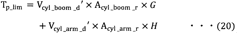
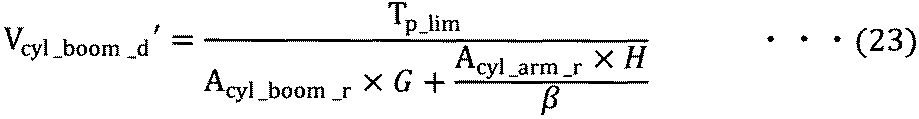
以上の様に制御することにより、レバー51の入力によって決定した各アクチュエータの要求速度比を保ったまま、エンジン9をラグダウンさせることなく油圧ショベル100を動作させることが可能になる。
制 御 By controlling as described above, it becomes possible to operate the excavator 100 without lagging down the engine 9 while maintaining the required speed ratio of each actuator determined by the input of the lever 51.
本実施例では、エンジン9と、エンジン9によって駆動される可変容量型の液圧ポンプ12~15と、液圧ポンプ12~15から吐出された圧液によって駆動される液圧アクチュエータ1,3と、液圧アクチュエータ1,3と液圧ポンプ12~15との接続を切換可能な制御弁40~47と、液圧アクチュエータ1,3の各負荷圧を検出する圧力検出装置60a,60b,61a,61bと、液圧アクチュエータ1,3の各動作方向および各要求速度を指示する操作装置51と、操作装置51からの入力に応じて液圧ポンプ12~15の各吐出流量を制御するコントローラ50とを備えた油圧ショベル100において、コントローラ50は、液圧アクチュエータ1,3の各要求速度と各負荷圧とに基づき、液圧ポンプ12~15がエンジン9に要求する各トルクの合計である要求トルクTp_dを推定する要求トルク推定部50cと、要求トルクTp_dの変化率である要求トルク変化率が所定の変化率(許容トルク変化率)を上回った場合に、前記要求トルク変化率が前記所定の変化率以下になるように液圧アクチュエータ1,3の各要求速度を制限する要求速度制限部50dと、前記要求トルクの変化率である要求トルク変化率が前記所定の変化率を上回った場合に、前記要求トルク変化率が前記所定の変化率以下になるように液圧アクチュエータ1,3の各要求速度を制限する要求速度制限部50dと、要求速度制限部50dによって制限された液圧アクチュエータ1,3の各要求速度に基づき、液圧アクチュエータ1,3に対する液圧ポンプ12~15の割り当てを決定し、液圧ポンプ12~15の各吐出流量を演算する指令演算部50eとを有する。
In this embodiment, the engine 9, variable displacement hydraulic pumps 12 to 15 driven by the engine 9, and hydraulic actuators 1 and 3 driven by hydraulic fluid discharged from the hydraulic pumps 12 to 15 Control valves 40 to 47 capable of switching the connection between the hydraulic actuators 1 and 3 and the hydraulic pumps 12 to 15, and pressure detecting devices 60a, 60b and 61a for detecting each load pressure of the hydraulic actuators 1 and 3. 61b, an operation device 51 for instructing each operation direction and each required speed of the hydraulic actuators 1 and 3, and a controller 50 for controlling each discharge flow rate of the hydraulic pumps 12 to 15 according to an input from the operation device 51. In the hydraulic excavator 100 including the hydraulic pumps 12 to 15, the hydraulic pumps 12 to 15 A required torque estimating unit 50c for estimating a required torque Tp_d, which is the sum of the torques required in the case where the required torque change rate, which is a change rate of the required torque Tp_d, exceeds a predetermined change rate (allowable torque change rate). A request speed limiter 50d that limits each required speed of the hydraulic actuators 1 and 3 so that the required torque change rate is equal to or less than the predetermined change rate; and a required torque change rate that is a change rate of the required torque. A required speed limiting unit 50d for limiting each required speed of the hydraulic actuators 1 and 3 so that the required torque change rate is equal to or less than the predetermined rate of change when the predetermined rate of change is exceeded; The assignment of the hydraulic pumps 12 to 15 to the hydraulic actuators 1 and 3 is determined based on the required speeds of the hydraulic actuators 1 and 3 limited by the section 50d. And a command calculation unit 50e for calculating each discharge flow rate of the pumps 12 to 15.
また、液圧ポンプ12,13は、それぞれ、一対の入出力ポートを有する両吐出型の液圧ポンプであり、制御弁40~43は、液圧ポンプ12,13と液圧アクチュエータ1,3との接続を切換可能な切換弁である。
Each of the hydraulic pumps 12 and 13 is a double-discharge hydraulic pump having a pair of input / output ports, and the control valves 40 to 43 are connected to the hydraulic pumps 12 and 13 and the hydraulic actuators 1 and 3, respectively. This is a switching valve that can switch the connection of.
以上のように構成した本実施例によれば、両吐出型の液圧ポンプ12,13からアクチュエータ1,3に供給される圧油の流れを切換弁40~43で制御する液圧駆動装置300を搭載した油圧ショベル100において、液圧アクチュエータ1,3の要求速度および液圧アクチュエータ1,3の負荷圧に基づいてエンジン9に対する要求トルクTp_dが推定され、要求トルク変化率が所定の変化率(許容トルク変化率)を上回った場合に、要求トルク変化率が所定の変化率以下になるように液圧アクチュエータ1,3の要求速度が制限される。これにより、オペレータの操作内容や液圧アクチュエータ1,3の負荷状態にかかわらず、エンジン9のラグダウンを抑制することが可能となる。
According to the present embodiment configured as described above, the hydraulic drive device 300 that controls the flow of the hydraulic oil supplied from the two-discharge type hydraulic pumps 12 and 13 to the actuators 1 and 3 by the switching valves 40 to 43. , The required torque Tp_d for the engine 9 is estimated based on the required speed of the hydraulic actuators 1 and 3 and the load pressure of the hydraulic actuators 1 and 3, and the required torque change rate becomes a predetermined change rate ( When the allowable torque change rate exceeds the allowable torque change rate, the required speed of the hydraulic actuators 1 and 3 is limited so that the required torque change rate is equal to or less than a predetermined change rate. This makes it possible to suppress a lag-down of the engine 9 irrespective of the operation contents of the operator and the load state of the hydraulic actuators 1 and 3.
また、指令演算部50eは、液圧アクチュエータ1,3のうちの1つの液圧アクチュエータに2台以上の液圧ポンプを割り当てた状態で、要求トルク変化率が所定の変化率(許容トルク変化率)を上回った場合に、要求速度制限部50dによって制限された前記1つの液圧アクチュエータの要求速度に応じて前記1つの液圧アクチュエータに割り当てる液圧ポンプの台数を減らすように構成されている。これにより、使用中の液圧ポンプの燃費効率を向上するとともに、未使用の液圧ポンプの台数を増やすことにより、新たに操作されるアクチュエータに対する液圧ポンプの割り当てが容易となる。
The command calculation unit 50e determines that the required torque change rate is a predetermined change rate (allowable torque change rate) in a state where two or more hydraulic pumps are assigned to one of the hydraulic actuators 1 and 3. ), The number of hydraulic pumps allocated to the one hydraulic actuator is reduced according to the required speed of the one hydraulic actuator limited by the required speed limiting unit 50d. This improves the fuel efficiency of the hydraulic pump in use and increases the number of unused hydraulic pumps, thereby facilitating assignment of the hydraulic pump to a newly operated actuator.
なお、本実施例では、式(1)によりレバー51の入力から要求シリンダ速度Vcyl_dが一意に決まるものとしたが、各アクチュエータの負荷状態や、レバー51の入力値のバランスにより、要求シリンダ速度Vcyl_dを変化させる計算機能をコントローラ50に持たせてもよい。
In the present embodiment, the required cylinder speed Vcyl_d is uniquely determined from the input of the lever 51 by Expression (1). However, the required cylinder speed Vcyl_d is determined by the load state of each actuator and the balance of the input value of the lever 51. May be provided in the controller 50.
本発明の第2の実施例に係る油圧ショベル100について、第1の実施例との相違点を中心に説明する。
The hydraulic excavator 100 according to the second embodiment of the present invention will be described focusing on the differences from the first embodiment.
図9は、本実施例における液圧駆動装置の概略構成図である。図9において、第1の実施例(図2に示す)との相違点は、アームシリンダ3を旋回モータ7に置き換えた点である。
FIG. 9 is a schematic configuration diagram of the hydraulic drive device in the present embodiment. In FIG. 9, the difference from the first embodiment (shown in FIG. 2) is that the arm cylinder 3 is replaced by a swing motor 7.
流路215は、旋回モータ7のaポートに接続されている。
The flow path 215 is connected to the port a of the turning motor 7.
流路216は、旋回モータ7のbポートに接続されている。
The flow path 216 is connected to the b port of the turning motor 7.
旋回モータ7は、作動油の供給を受けて回転する液圧モータである。旋回モータ7の回転方向は作動油の供給方向に依存する。
The turning motor 7 is a hydraulic motor that rotates by receiving a supply of hydraulic oil. The rotation direction of the swing motor 7 depends on the supply direction of the working oil.
流路215,216に設けられたリリーフ弁37a,37bは、流路圧が所定の圧力以上になったときに、作動油を、チャージ用リリーフ弁20を介して、タンク25に逃がし回路を保護する。
The relief valves 37a and 37b provided in the flow passages 215 and 216 allow the hydraulic oil to escape to the tank 25 via the charging relief valve 20 and protect the circuit when the flow passage pressure becomes equal to or higher than a predetermined pressure. I do.
流路215,216に設けられたフラッシング弁38は、流路内の余剰油を、チャージ用リリーフ弁20を介して、タンク25に排出する。
The flushing valve 38 provided in the flow passages 215 and 216 discharges excess oil in the flow passage to the tank 25 via the charging relief valve 20.
流路215に接続された圧力センサ62aは、流路215の圧力を計測し、コントローラ50に入力する。圧力センサ62aは、流路215の圧力を計測することにより、旋回モータ7のaポート圧力Pswing_aを計測する。
The pressure sensor 62 a connected to the flow path 215 measures the pressure in the flow path 215 and inputs the measured pressure to the controller 50. The pressure sensor 62a measures the pressure in the flow path 215 to measure the a-port pressure Pswing_a of the swing motor 7.
流路216に接続された圧力センサ62bは、流路216の圧力を計測し、コントローラ50に入力する。圧力センサ62bは、流路216の圧力を計測することにより、旋回モータ7のbポート圧力Pswing_bを計測する。
The pressure sensor 62b connected to the flow path 216 measures the pressure in the flow path 216 and inputs the measured pressure to the controller 50. The pressure sensor 62b measures the b-port pressure Pswing_b of the swing motor 7 by measuring the pressure in the flow path 216.
図10は、図9に示すコントローラ50のポンプ負荷トルク制御の流れを示すフローチャートである。図10において、第1の実施例(図5に示す)との相違点は、ステップS5に代えて、ステップS5a~S5fを備えている点である。以下、相違点を説明する。
FIG. 10 is a flowchart showing a flow of the pump load torque control of the controller 50 shown in FIG. 10 differs from the first embodiment (shown in FIG. 5) in that steps S5a to S5f are provided instead of step S5. Hereinafter, the differences will be described.
ステップS5aにおいて、コントローラ50は、ブーム及び旋回の複合操作が行われている場合はステップS5bに進み、そうでない場合はステップS5fに進む。
In step S5a, the controller 50 proceeds to step S5b if the combined operation of the boom and the turn is performed, and proceeds to step S5f otherwise.
ステップS5bにおいて、コントローラ50は、旋回モータ7の要求トルクが全体の許容トルクTp_limの所定の割合以下になるように旋回モータ7の要求速度を制限する。
In step S5b, the controller 50 limits the required speed of the swing motor 7 so that the required torque of the swing motor 7 is equal to or less than a predetermined ratio of the total allowable torque Tp_lim.
ステップS5cにおいて、コントローラ50は、要求速度を制限した旋回モータ7の要求トルクと他の旋回モータ7以外のアクチュエータの要求トルクの合計が全体の許容トルクTp_limを超える場合はステップS5dに進み、そうでない場合はステップS5eに進む。
In step S5c, the controller 50 proceeds to step S5d if the sum of the required torque of the swing motor 7 having the limited required speed and the required torque of the actuators other than the other swing motors 7 exceeds the total allowable torque Tp_lim, and otherwise proceeds to step S5d. In this case, the process proceeds to step S5e.
ステップS5dにおいて、コントローラ50は、レバー51の入力値Linから旋回モータ7以外のアクチュエータの要求速度を決定する。
In step S5d, the controller 50 determines a required speed of an actuator other than the swing motor 7 from the input value Lin of the lever 51.
ステップS5eにおいて、コントローラ50は、各アクチュエータの要求速度比を保ったまま各アクチュエータの要求トルクの合計が全体の許容トルクTp_lim以下になるように、旋回モータ7以外のアクチュエータの要求速度を制限する。
In step S5e, the controller 50 limits the required speeds of the actuators other than the swing motor 7 so that the total required torque of each actuator is equal to or less than the total allowable torque Tp_lim while maintaining the required speed ratio of each actuator.
ステップS5fにおいて、コントローラ50は、各アクチュエータの要求速度比を保ったまま各アクチュエータの要求トルクの合計が全体の許容トルクTp_lim以下となるように、各アクチュエータの要求速度を制限する。
In step S5f, the controller 50 limits the required speed of each actuator so that the total required torque of each actuator is equal to or less than the total allowable torque Tp_lim while maintaining the required speed ratio of each actuator.
次に、図9に示した液圧駆動装置300Aの動作を説明する。
Next, the operation of the hydraulic drive device 300A shown in FIG. 9 will be described.
(1)非操作時
図9において、レバー51が非操作時は、第1~第4の液圧ポンプ12~15は全て最小傾転角に制御され、切換弁40~44,46は全て閉じられ、ブームシリンダ1および旋回モータ7は停止状態で保持される。 (1) Non-operation In FIG. 9, when thelever 51 is not operated, the first to fourth hydraulic pumps 12 to 15 are all controlled to the minimum tilt angles, and the switching valves 40 to 44 and 46 are all closed. Then, the boom cylinder 1 and the swing motor 7 are held in a stopped state.
図9において、レバー51が非操作時は、第1~第4の液圧ポンプ12~15は全て最小傾転角に制御され、切換弁40~44,46は全て閉じられ、ブームシリンダ1および旋回モータ7は停止状態で保持される。 (1) Non-operation In FIG. 9, when the
(2)ブーム上げ+旋回動作時
図11に、液圧駆動装置300でブームシリンダ1の伸長動作と旋回モータ7の旋回動作とを同時に行った場合のレバー51の入力、レバー51の入力に基づく要求シリンダ速度と要求旋回速度、圧力センサ60a,60bで計測したブームシリンダ1のヘッド室圧力とロッド室圧力、圧力センサ62a,62bで計測した旋回モータ7のaポート圧力とbポート圧力、第1~第3の液圧ポンプ12~14の各要求吐出流量、エンジン負荷トルク、および第1~第3の液圧ポンプ12~14の各吐出流量の変化を示す。 (2) Boom Raising + Swing Operation FIG. 11 is based on the input of thelever 51 and the input of the lever 51 when the extension operation of the boom cylinder 1 and the turning operation of the swing motor 7 are simultaneously performed by the hydraulic pressure driving device 300. The required cylinder speed and the required swing speed, the head chamber pressure and the rod chamber pressure of the boom cylinder 1 measured by the pressure sensors 60a and 60b, the a port pressure and the b port pressure of the swing motor 7 measured by the pressure sensors 62a and 62b, The change of each required discharge flow rate of the third to third hydraulic pumps 12 to 14, the engine load torque, and the change of each discharge flow rate of the first to third hydraulic pumps 12 to 14 are shown.
図11に、液圧駆動装置300でブームシリンダ1の伸長動作と旋回モータ7の旋回動作とを同時に行った場合のレバー51の入力、レバー51の入力に基づく要求シリンダ速度と要求旋回速度、圧力センサ60a,60bで計測したブームシリンダ1のヘッド室圧力とロッド室圧力、圧力センサ62a,62bで計測した旋回モータ7のaポート圧力とbポート圧力、第1~第3の液圧ポンプ12~14の各要求吐出流量、エンジン負荷トルク、および第1~第3の液圧ポンプ12~14の各吐出流量の変化を示す。 (2) Boom Raising + Swing Operation FIG. 11 is based on the input of the
時刻t0から時刻t1にかけて、レバー51の入力は0であり、ブームシリンダ1と旋回モータ7は静止している。
、 From time t0 to time t1, the input of the lever 51 is 0, and the boom cylinder 1 and the swing motor 7 are stationary.
時刻t1から時刻t2にかけて、レバー51の入力はブームシリンダ1を伸長する指令値と、旋回モータ7を回転する指令値が最大値まで上げられる。
か け て From time t1 to time t2, the input value of the lever 51 increases the command value for extending the boom cylinder 1 and the command value for rotating the swing motor 7 to the maximum value.
図5に示す処理フローによれば、図11に示す時刻t1から時刻t2にかけて、レバー51の入力がブームシリンダ1と、旋回モータ7を回転する指令値が最大値まで上げられると、コントローラ50は、レバー51の入力から要求ブームシリンダ速度Vcyl_boom_dと、要求旋回速度Wswing_dを計算する。
According to the processing flow shown in FIG. 5, when the input of the lever 51 is increased to the maximum value from the time t1 to the time t2 shown in FIG. The required boom cylinder speed Vcyl_boom_d and the required swing speed Wswing_d are calculated from the input of the lever 51.
ここで、コントローラ50は、ブームシリンダ1の駆動用に第1の液圧ポンプ12と第3の液圧ポンプ14を、旋回モータ7の駆動用に第2の液圧ポンプ13を割り当てる。
Here, the controller 50 allocates the first hydraulic pump 12 and the third hydraulic pump 14 for driving the boom cylinder 1 and the second hydraulic pump 13 for driving the swing motor 7.
コントローラ50は、要求ブームシリンダ速度Vcyl_boom_dから、式(2),(4)を用いて、第1の液圧ポンプ12の要求吐出流量Qcp12_dを計算する。
The controller 50 calculates the required discharge flow rate Qcp12_d of the first hydraulic pump 12 from the required boom cylinder speed Vcyl_boom_d using the equations (2) and (4).
ここで、旋回モータ7の吐出容積をDswingとすると、旋回モータ7から流出する流量Qswingは、
Here, assuming that the discharge volume of the swing motor 7 is Dswing, the flow rate Qswing flowing out of the swing motor 7 is
コントローラ50は、要求ブームシリンダ速度Vcyl_boom_dから、式(3),(5)を用いて、第3の液圧ポンプ14の要求吐出流量Qop14_dを計算する。
The controller 50 calculates the required discharge flow rate Qop14_d of the third hydraulic pump 14 from the required boom cylinder speed Vcyl_boom_d using the equations (3) and (5).
コントローラ50は、計算した要求流量と、圧力センサ60a,60bで計測したブームシリンダ1のヘッド室圧力とロッド室圧力、圧力センサ62a,62bで計測した旋回モータ7のaポート圧力Pswing_aとbポート圧力Pswing_aから、式(8),(9)を用いて、第1の液圧ポンプ12の要求トルクTcp12_d、第2の液圧ポンプ13の要求トルクTcp13_d、および第3の液圧ポンプ14の要求トルクTop14_dを計算する。この時、要求トルクTp_dは、
The controller 50 calculates the required flow rate, the head chamber pressure and the rod chamber pressure of the boom cylinder 1 measured by the pressure sensors 60a and 60b, and the a port pressure Pswing_a and the b port pressure of the swing motor 7 measured by the pressure sensors 62a and 62b. From Pswing_a, using equations (8) and (9), the required torque Tcp12_d of the first hydraulic pump 12, the required torque Tcp13_d of the second hydraulic pump 13, and the required torque of the third hydraulic pump 14 Calculate Top14_d. At this time, the required torque Tp_d is
図11に示す通り、要求トルクTp_dが時刻t1から時刻t2にかけて最大値に増加するのに対して、エンジン9の許容トルクTp_limが、エンジン9の定格最大トルクになるのに時刻t1から時刻t3までかかるとすると、時刻t1から時刻t3にかけて、コントローラ50は、
As shown in FIG. 11, the required torque Tp_d increases to the maximum value from the time t1 to the time t2, while the allowable torque Tp_lim of the engine 9 becomes the rated maximum torque of the engine 9 from the time t1 to the time t3. In this case, from time t1 to time t3, the controller 50
ここで、一般的な建設機械が平地で旋回動作を行う場合、図11に示すとおり、停止中にはaポート圧とbポート圧が低く、旋回加速中に片側ポートの圧力が上がるという特徴がある。特に最大加速度で旋回する場合、片側のポート圧力は、リリーフ弁37a,37bの設定圧力まで上昇する。従って、最大加速度を越えるような要求速度が入力される場合、要求通りの流量をポンプから供給すると、一部の流量はリリーフ弁37a,37bの一方からタンク25へ排出され無駄になってしまう。
Here, when a general construction machine performs a turning operation on a flat ground, as shown in FIG. 11, a characteristic is that the port a pressure and the port b pressure are low during stoppage, and the pressure at one port increases during turning acceleration. is there. In particular, when turning at the maximum acceleration, the port pressure on one side rises to the set pressure of the relief valves 37a and 37b. Therefore, when a required speed exceeding the maximum acceleration is input, if a required flow rate is supplied from the pump, a part of the flow rate is discharged from one of the relief valves 37a and 37b to the tank 25 and is wasted.
例えば、第1の実施例の(4)ブーム上げ+アームダンプ動作時の様に、2つのアクチュエータの要求速度比を合わせようと制御する場合、旋回モータ7においては、一部の流量がリリーフ弁37a、または37bから排出され、旋回速度が出ないのみならず、ブームシリンダ1の速度も低くなってしまうことがある。
For example, when controlling to match the required speed ratio of the two actuators as in the case of (4) boom raising + arm dumping operation of the first embodiment, in the swing motor 7, a part of the flow rate is reduced by the relief valve. It is discharged from 37a or 37b, and not only the turning speed does not come out, but also the speed of the boom cylinder 1 may decrease.
これを抑制するために、ブームシリンダ1と旋回モータ7を組み合わせて動かす場合、旋回モータ7に割り当てる馬力の比率をブームシリンダ1に割り当てる馬力の比率よりも低く設定する。すなわち、エンジン9が出力可能な馬力の50%以下(例えば20%)を旋回モータ7に割り当てる。式(28)より、
抑制 す る To suppress this, when moving the boom cylinder 1 and the swing motor 7 in combination, the ratio of the horsepower assigned to the swing motor 7 is set lower than the ratio of the horsepower assigned to the boom cylinder 1. That is, 50% or less (for example, 20%) of the horsepower that can be output by the engine 9 is allocated to the turning motor 7. From equation (28),
となり、
Becomes
式(2),(7),(8),(9),(24),(25)より、
よ り From equations (2), (7), (8), (9), (24), and (25),

本実施例では、液圧アクチュエータ1,7は、1つ以上の液圧シリンダ1と、1つ以上の液圧モータ7とを含み、指令演算部50eは、液圧シリンダ1と液圧モータ7とを同時に駆動している状態で、要求トルク変化率が所定の変化率(許容トルク変化率)を上回った場合に、液圧モータ7に割り当てた液圧ポンプの要求トルクがエンジン9の出力トルクの所定の割合(例えば20%)以下となるように液圧ポンプ12~15の各吐出流量を演算する。
In this embodiment, the hydraulic actuators 1 and 7 include one or more hydraulic cylinders 1 and one or more hydraulic motors 7, and the command calculation unit 50e includes the hydraulic cylinder 1 and the hydraulic motor 7 When the required torque change rate exceeds a predetermined change rate (permissible torque change rate) in a state where the motors are simultaneously driven, the required torque of the hydraulic pump assigned to the hydraulic motor 7 is changed to the output torque of the engine 9. The respective discharge flow rates of the hydraulic pumps 12 to 15 are calculated so as to be equal to or less than a predetermined ratio (for example, 20%).
以上のように構成した本実施例に係る油圧ショベル100によれば、旋回開始時の旋回モータ7の圧力上昇に伴いブームシリンダ1の速度が著しく低下することを抑制しつつ、エンジン9をラグダウンさせることなく油圧ショベル100を動作させることが可能になる。
According to the hydraulic excavator 100 according to the present embodiment configured as described above, the engine 9 is lagged down while the speed of the boom cylinder 1 is not significantly reduced due to the pressure increase of the swing motor 7 at the start of swing. The excavator 100 can be operated without the need for this.
本発明の第3の実施例に係る油圧ショベル100について、第1の実施例との相違点を中心に説明する。
油 圧 A description will be given of a hydraulic shovel 100 according to a third embodiment of the present invention, focusing on differences from the first embodiment.
図12は、本実施例における液圧駆動装置の概略構成図であり、図13は、本実施例におけるコントローラ50の機能ブロック図である。図12および図13において、第1の実施例(図2および図3に示す)との相違点は、閉回路の構成要素を除いた点と、液圧ポンプ13,14と液圧アクチュエータ1,3との接続を切換可能な切換弁44~47を流量制御弁71~74に置き換えた点である。
FIG. 12 is a schematic configuration diagram of the hydraulic drive device in the present embodiment, and FIG. 13 is a functional block diagram of the controller 50 in the present embodiment. 12 and 13, the difference from the first embodiment (shown in FIGS. 2 and 3) is that the components of the closed circuit are eliminated, and that the hydraulic pumps 13 and 14 and the hydraulic actuators 1 and 2 are different. 3 in that the switching valves 44 to 47 capable of switching the connection with the third valve 3 are replaced with flow control valves 71 to 74.
流量制御弁71は、流路204、タンク25、流路210、および流路211に接続される。流量制御弁71に信号が入力されてない場合、流量制御弁72は、流路204とタンク25を接続し、流路210と流路211に接続されたポートを閉じる。流量制御弁71に正の信号が入力されると、流量制御弁71は、流路204と流路210を接続し、タンク25と流路211を接続する。また、負の信号が入力されると、流量制御弁71は、流路204と流路211を接続し、タンク25と流路210を接続する。正負の信号の大きさに応じて、各流路を接続する流路の開口面積が変化する。
The flow control valve 71 is connected to the flow path 204, the tank 25, the flow path 210, and the flow path 211. When a signal is not input to the flow control valve 71, the flow control valve 72 connects the flow path 204 and the tank 25 and closes a port connected to the flow path 210 and the flow path 211. When a positive signal is input to the flow control valve 71, the flow control valve 71 connects the flow path 204 and the flow path 210, and connects the tank 25 and the flow path 211. When a negative signal is input, the flow control valve 71 connects the flow path 204 to the flow path 211 and connects the tank 25 to the flow path 210. The opening area of the flow path connecting each flow path changes according to the magnitude of the positive or negative signal.
流量制御弁72は、流路204、タンク25、流路213、および流路214に接続される。流量制御弁72に信号がない場合、流量制御弁72は、流路204とタンク25を接続し、流路213と流路214に接続されたポートを閉じる。流量制御弁72に正の信号が入力されると、流量制御弁72は、流路204と流路213を接続し、タンク25と流路214を接続する。また、負の信号が入力されると、流量制御弁71は、流路204と流路214を接続し、タンク25と流路213を接続する。正負の信号の大きさに応じて、各流路を接続する流路の開口面積が変化する。
The flow control valve 72 is connected to the flow path 204, the tank 25, the flow path 213, and the flow path 214. When there is no signal at the flow control valve 72, the flow control valve 72 connects the flow path 204 and the tank 25, and closes the ports connected to the flow paths 213 and 214. When a positive signal is input to the flow control valve 72, the flow control valve 72 connects the flow path 204 and the flow path 213, and connects the tank 25 and the flow path 214. When a negative signal is input, the flow control valve 71 connects the flow path 204 to the flow path 214 and connects the tank 25 to the flow path 213. The opening area of the flow path connecting each flow path changes according to the magnitude of the positive or negative signal.
流量制御弁73は、流路205、タンク25、流路210、および流路211に接続される。流量制御弁73に信号が入力されていない場合、流量制御弁73は、流路205とタンク25を接続し、流路210と流路211に接続されたポートを閉じる。流量制御弁73に正の信号が入力されると、流量制御弁73は、流路205と流路210を接続し、タンク25と流路211を接続する。また、負の信号が入力されると、流量制御弁73は、流路205と流路211を接続し、タンク25と流路210を接続する。正負の信号の大きさに応じて、各流路を接続する流路の開口面積が変化する。
The flow control valve 73 is connected to the flow path 205, the tank 25, the flow path 210, and the flow path 211. When no signal is input to the flow control valve 73, the flow control valve 73 connects the flow path 205 to the tank 25 and closes a port connected to the flow path 210 and the flow path 211. When a positive signal is input to the flow control valve 73, the flow control valve 73 connects the flow path 205 to the flow path 210 and connects the tank 25 to the flow path 211. When a negative signal is input, the flow control valve 73 connects the flow path 205 to the flow path 211 and connects the tank 25 to the flow path 210. The opening area of the flow path connecting each flow path changes according to the magnitude of the positive or negative signal.
流量制御弁74は、流路205、タンク25、流路213、および流路214に接続される。流量制御弁74に信号が入力されていない場合、流量制御弁72は、流路205とタンク25を接続し、流路213と流路214に接続されたポートを閉じる。流量制御弁74に正の信号が入力されると、流量制御弁74は、流路205と流路213を接続し、タンク25と流路214を接続する。また、負の信号が入力されると、流量制御弁74は、流路205と流路214を接続し、タンク25と流路213を接続する。正負の信号の大きさに応じて、各流路を接続する流路の開口面積が変化する。
The flow control valve 74 is connected to the flow path 205, the tank 25, the flow path 213, and the flow path 214. When no signal is input to the flow control valve 74, the flow control valve 72 connects the flow path 205 and the tank 25, and closes the ports connected to the flow paths 213 and 214. When a positive signal is input to the flow control valve 74, the flow control valve 74 connects the flow path 205 and the flow path 213, and connects the tank 25 and the flow path 214. When a negative signal is input, the flow control valve 74 connects the flow path 205 to the flow path 214 and connects the tank 25 to the flow path 213. The opening area of the flow path connecting each flow path changes according to the magnitude of the positive or negative signal.
図12に示す液圧駆動装置300Bにおいて、流量制御弁71~74で発生する圧力損失を見積もれば、第1の実施例に示したのと同様に、レバー51の入力によって決定した各アクチュエータの要求速度比を保ったまま、エンジン9をラグダウンさせることなく油圧ショベル100を動作させることが可能となる。なお、流量制御弁71~74を最大開口面積で使用し、液圧ポンプ14,15の吐出流量で、ブームシリンダ1、およびアームシリンダ3の速度を制御すれば、流量制御弁71~74で発生する圧力損失は推定しやすくなる。
In the hydraulic driving device 300B shown in FIG. 12, if the pressure loss generated in the flow control valves 71 to 74 is estimated, the demands of the actuators determined by the input of the lever 51 can be determined in the same manner as in the first embodiment. It is possible to operate the excavator 100 without lagging down the engine 9 while maintaining the speed ratio. If the flow control valves 71 to 74 are used with the maximum opening area and the speeds of the boom cylinder 1 and the arm cylinder 3 are controlled by the discharge flow rates of the hydraulic pumps 14 and 15, the flow control valves 71 to 74 are generated. The resulting pressure loss is easier to estimate.
本実施例に係る油圧ショベル100は、液圧ポンプ13,14と、液圧アクチュエータ1,3と、液圧アクチュエータ1,3と液圧ポンプ13,14との接続を切換可能な制御弁71~74とを備え、圧力検出装置60a,60b,61a,61bは、液圧アクチュエータ1,3の各負荷圧を検出可能であり、操作装置51は、液圧アクチュエータ1,3の各動作方向および各要求速度を指示可能であり、要求トルク推定部50cは、液圧アクチュエータ1,3の各要求速度と各負荷圧とに基づき、液圧ポンプ13,14がエンジン9に要求する各トルクの合計である要求トルクを推定し、要求速度制限部50dは、前記要求トルクの変化率である要求トルク変化率が所定の変化率(許容トルク変化率)を上回った場合に、前記要求トルク変化率が前記所定の変化率以下になるように液圧アクチュエータ1,3の各要求速度を制限し、指令演算部50eは、要求速度制限部50dによって制限された液圧アクチュエータ1,3の各要求速度に基づき、液圧アクチュエータ1,3に対する液圧ポンプ13,14の割り当てを決定し、液圧ポンプ13,14の各吐出流量を演算する。
The hydraulic excavator 100 according to the present embodiment includes hydraulic pumps 13 and 14, hydraulic actuators 1 and 3, and control valves 71 to which connection between the hydraulic actuators 1 and 3 and the hydraulic pumps 13 and 14 can be switched. 74, the pressure detecting devices 60a, 60b, 61a, 61b can detect the respective load pressures of the hydraulic actuators 1, 3, and the operating device 51 can control the operating directions and the operating directions of the hydraulic actuators 1, 3 respectively. The required speed can be instructed, and the required torque estimating unit 50c calculates the sum of the torques required by the hydraulic pumps 13 and 14 for the engine 9 based on the required speeds and the load pressures of the hydraulic actuators 1 and 3. When a required torque is estimated, the required speed limiting unit 50d determines that the required torque change rate, which is the rate of change of the required torque, exceeds a predetermined rate of change (permissible torque change rate). The required speeds of the hydraulic actuators 1 and 3 are limited so that the rate of change becomes equal to or less than the predetermined change rate. The assignment of the hydraulic pumps 13 and 14 to the hydraulic actuators 1 and 3 is determined based on the required speed, and the respective discharge flow rates of the hydraulic pumps 13 and 14 are calculated.
また、液圧ポンプ14,15は、それぞれ、吸込ポートと吐出ポートとを有する片吐出型の液圧ポンプであり、液圧アクチュエータ1,3と液圧ポンプ14,15との接続を切換可能な制御弁71~74は、液圧ポンプ14,15から液圧アクチュエータ1,3に供給される圧液の方向および流量を調整可能な流量制御弁である。
The hydraulic pumps 14 and 15 are single-discharge hydraulic pumps each having a suction port and a discharge port, and can switch the connection between the hydraulic actuators 1 and 3 and the hydraulic pumps 14 and 15. The control valves 71 to 74 are flow rate control valves capable of adjusting the direction and flow rate of the hydraulic fluid supplied from the hydraulic pumps 14 and 15 to the hydraulic actuators 1 and 3.
以上のように構成した本実施例によれば、液圧アクチュエータ1,3と液圧ポンプ13,14との接続を流量制御弁71~74で切換可能な液圧駆動装置300Bが搭載された油圧ショベル100において、第1の実施例と同様に、オペレータの操作内容やアクチュエータ1,3の負荷状態にかかわらず、エンジン9のラグダウンを抑制することが可能となる。
According to the present embodiment configured as described above, the hydraulic drive 300B equipped with the hydraulic drive device 300B capable of switching the connection between the hydraulic actuators 1, 3 and the hydraulic pumps 13, 14 by the flow control valves 71 to 74 is mounted. In the shovel 100, as in the first embodiment, it is possible to suppress the engine 9 from lagging down regardless of the operation content of the operator and the load state of the actuators 1 and 3.
以上、本発明の実施例について詳述したが、本発明は、上記した実施例に限定されるものではなく、様々な変形例が含まれる。例えば、上記した実施例は、本発明を分かり易く説明するために詳細に説明したものであり、必ずしも説明した全ての構成を備えるものに限定されるものではない。また、ある実施例の構成に他の実施例の構成の一部を加えることも可能であり、ある実施例の構成の一部を削除し、あるいは、他の実施例の一部と置き換えることも可能である。
Although the embodiments of the present invention have been described in detail above, the present invention is not limited to the above-described embodiments, and includes various modifications. For example, the above-described embodiments have been described in detail for easy understanding of the present invention, and are not necessarily limited to those having all the configurations described above. It is also possible to add a part of the configuration of another embodiment to the configuration of a certain embodiment, delete a part of the configuration of one embodiment, or replace it with a part of another embodiment. It is possible.
1…ブームシリンダ(液圧シリンダ、液圧アクチュエータ)、1a…ヘッド室、1b…ロッド室、2…ブーム、3…アームシリンダ(液圧シリンダ、液圧アクチュエータ)、3a…ヘッド室、3b…ロッド室、4…アーム、5…バケットシリンダ(液圧シリンダ、液圧アクチュエータ)、6…バケット、7…旋回モータ(液圧モータ、液圧アクチュエータ)、8…走行装置、9…エンジン、10…動力伝達装置、11…チャージポンプ、12…第1の液圧ポンプ、12a…レギュレータ、13…第2の液圧ポンプ、13a…レギュレータ、14…第3の液圧ポンプ、14a…レギュレータ、15…第4の液圧ポンプ、15a…レギュレータ、20…チャージ用リリーフ弁、21,22…リリーフ弁、25…タンク、26,27,28a,28b,29a,29b…チャージ用チェック弁、30a,30b,31a,31b,32a,32b,33a,33b…リリーフ弁、34,35…フラッシング弁、36a,36b…チャージ用チェック弁、37a,37b…リリーフ弁、38…フラッシング弁、40~47…切換弁(制御弁)、48,49…比例弁、50…コントローラ、50a…要求速度演算部、50b…アクチュエータ圧力演算部、50c…要求トルク推定部、50d…要求速度制限部、50e…指令演算部、51…レバー(操作装置)、60a,60b,61a,61b,62a,62b…圧力センサ(圧力検出装置)、71~74…流量制御弁(制御弁)、100…油圧ショベル、101…下部走行体、102…上部旋回体、103…フロント作業装置、104…キャブ、200~216…流路、300,300A,300B…液圧駆動装置。
DESCRIPTION OF SYMBOLS 1 ... Boom cylinder (hydraulic cylinder, hydraulic actuator), 1a ... head chamber, 1b ... rod chamber, 2 ... boom, 3 ... arm cylinder (hydraulic cylinder, hydraulic actuator), 3a ... head chamber, 3b ... rod Chamber, 4 ... Arm, 5 ... Bucket cylinder (hydraulic cylinder, hydraulic actuator), 6 ... Bucket, 7 ... Swing motor (hydraulic motor, hydraulic actuator), 8 ... Traveling device, 9 ... Engine, 10 ... Power Transmission device, 11: charge pump, 12: first hydraulic pump, 12a: regulator, 13: second hydraulic pump, 13a: regulator, 14: third hydraulic pump, 14a: regulator, 15: first 4 hydraulic pump, 15a regulator, 20 relief valve for charging, 21, 22 relief valve, 25 tank, 26, 27, 28a, 2 b, 29a, 29b ... charge check valve, 30a, 30b, 31a, 31b, 32a, 32b, 33a, 33b ... relief valve, 34, 35 ... flushing valve, 36a, 36b ... charge check valve, 37a, 37b ... Relief valve, 38: Flushing valve, 40 to 47: Switching valve (control valve), 48, 49: Proportional valve, 50: Controller, 50a: Requested speed calculator, 50b: Actuator pressure calculator, 50c: Requested torque estimator , 50d: required speed limiter, 50e: command calculator, 51: lever (operating device), 60a, 60b, 61a, 61b, 62a, 62b: pressure sensor (pressure detecting device), 71 to 74: flow control valve ( Control valve), 100: hydraulic excavator, 101: lower traveling structure, 102: upper revolving structure, 103: front working device, 104: Catcher Bed, 200-216 ... passage, 300, 300A, 300B ... hydraulic drive.
Claims (7)
- エンジンと、
前記エンジンによって駆動される可変容量型の第1液圧ポンプと、
前記第1液圧ポンプから吐出された圧液によって駆動される第1液圧アクチュエータと、
前記第1液圧アクチュエータの動作方向および要求速度を指示する操作装置と、
前記操作装置からの入力に応じて前記第1液圧ポンプの吐出流量を制御するコントローラとを備えた建設機械において、
前記第1液圧アクチュエータの負荷圧を検出する圧力検出装置を備え、
前記コントローラは、
前記第1液圧アクチュエータの要求速度と前記第1液圧アクチュエータの負荷圧とに基づき、前記第1液圧ポンプが前記エンジンに要求するトルクである要求トルクを推定する要求トルク推定部と、
前記要求トルクの変化率である要求トルク変化率が所定の変化率を上回った場合に、前記要求トルク変化率が前記所定の変化率以下になるように前記要求速度を制限する要求速度制限部と、
前記要求速度制限部によって制限された前記第1液圧アクチュエータの要求速度に基づき、前記第1液圧ポンプの吐出流量を演算する指令演算部とを有する
ことを特徴とする建設機械。 Engine and
A variable displacement first hydraulic pump driven by the engine;
A first hydraulic actuator driven by a hydraulic fluid discharged from the first hydraulic pump;
An operating device for instructing an operation direction and a required speed of the first hydraulic actuator;
A controller that controls a discharge flow rate of the first hydraulic pump in accordance with an input from the operating device,
A pressure detection device for detecting a load pressure of the first hydraulic actuator,
The controller is
A required torque estimating unit that estimates a required torque that is a torque required by the first hydraulic pump to the engine based on a required speed of the first hydraulic actuator and a load pressure of the first hydraulic actuator;
A request speed limiting unit that limits the required speed so that the required torque change rate is equal to or less than the predetermined change rate when the required torque change rate that is the change rate of the required torque exceeds a predetermined change rate; ,
And a command calculation unit for calculating a discharge flow rate of the first hydraulic pump based on a required speed of the first hydraulic actuator limited by the required speed limiting unit. - 請求項1に記載の建設機械において、
前記第1液圧ポンプを含む複数の液圧ポンプと、
前記第1液圧アクチュエータを含む複数の液圧アクチュエータと、
前記複数の液圧アクチュエータと前記複数の液圧ポンプとの接続を切換可能な複数の制御弁とを備え、
前記圧力検出装置は、前記複数の液圧アクチュエータの各負荷圧を検出可能であり、
前記操作装置は、前記複数の液圧アクチュエータの各動作方向および各要求速度を指示可能であり、
前記要求トルク推定部は、前記複数の液圧アクチュエータの各要求速度と各負荷圧とに基づき、前記複数の液圧ポンプが前記エンジンに要求する各トルクの合計である要求トルクを推定し、
前記要求速度制限部は、前記要求トルクの変化率である要求トルク変化率が前記所定の変化率を上回った場合に、前記要求トルク変化率が前記所定の変化率以下になるように前記複数の液圧アクチュエータの各要求速度を制限し、
前記指令演算部は、前記要求速度制限部によって制限された前記複数の液圧アクチュエータの各要求速度に基づき、前記複数の液圧アクチュエータに対する前記複数の液圧ポンプの割り当てを決定し、前記複数の液圧ポンプの各吐出流量を演算する
ことを特徴とする建設機械。 The construction machine according to claim 1,
A plurality of hydraulic pumps including the first hydraulic pump;
A plurality of hydraulic actuators including the first hydraulic actuator;
A plurality of control valves capable of switching the connection between the plurality of hydraulic actuators and the plurality of hydraulic pumps,
The pressure detector is capable of detecting each load pressure of the plurality of hydraulic actuators,
The operating device is capable of indicating each operation direction and each required speed of the plurality of hydraulic actuators,
The required torque estimating unit estimates a required torque that is a sum of respective torques required by the plurality of hydraulic pumps to the engine, based on the required speeds and the respective load pressures of the plurality of hydraulic actuators,
The request speed limiting unit is configured to, when a request torque change rate that is a change rate of the request torque exceeds the predetermined change rate, cause the plurality of the plurality of request torques to be equal to or less than the predetermined change rate. Limiting each required speed of the hydraulic actuator,
The command calculation unit determines an assignment of the plurality of hydraulic pumps to the plurality of hydraulic actuators based on each required speed of the plurality of hydraulic actuators limited by the required speed limiting unit, A construction machine which calculates each discharge flow rate of a hydraulic pump. - 請求項2に記載の建設機械において、
前記指令演算部は、前記複数の液圧アクチュエータのうちの1つの液圧アクチュエータに2台以上の液圧ポンプを割り当てた状態で、前記要求トルク変化率が前記所定の変化率を上回った場合に、前記要求速度制限部によって制限された前記1つの液圧アクチュエータの要求速度に応じて前記1つの液圧アクチュエータに割り当てる液圧ポンプの台数を減らすように構成されている
ことを特徴とする建設機械。 The construction machine according to claim 2,
The command calculation unit may be configured such that in a state where two or more hydraulic pumps are assigned to one hydraulic actuator among the plurality of hydraulic actuators, the requested torque change rate exceeds the predetermined change rate. A construction machine configured to reduce the number of hydraulic pumps assigned to the one hydraulic actuator in accordance with the required speed of the one hydraulic actuator limited by the required speed limiting unit. . - 請求項2に記載の建設機械において、
前記複数の液圧アクチュエータは、1つ以上の液圧シリンダと、1つ以上の液圧モータとを含み、
前記指令演算部は、前記液圧シリンダと前記液圧モータとを同時に駆動している状態で、前記要求トルク変化率が前記所定の変化率を上回った場合に、前記液圧モータに割り当てた液圧ポンプの要求トルクが前記エンジンの出力トルクの所定の割合以下となるように前記複数の液圧ポンプの各吐出流量を演算する
ことを特徴とする建設機械。 The construction machine according to claim 2,
The plurality of hydraulic actuators include one or more hydraulic cylinders and one or more hydraulic motors,
The command calculation unit is configured to control the hydraulic pressure allocated to the hydraulic motor when the required torque change rate exceeds the predetermined change rate in a state where the hydraulic cylinder and the hydraulic motor are simultaneously driven. A construction machine, wherein each discharge flow rate of the plurality of hydraulic pumps is calculated so that the required torque of the pressure pump is equal to or less than a predetermined ratio of the output torque of the engine. - 請求項4に記載の建設機械において、
前記所定の割合が50%以下に設定されている
ことを特徴する建設機械。 The construction machine according to claim 4,
The construction machine, wherein the predetermined ratio is set to 50% or less. - 請求項2に記載の建設機械において、
前記複数の液圧ポンプは、それぞれ、一対の入出力ポートを有する両吐出型の液圧ポンプであり、
前記複数の制御弁は、前記複数の液圧ポンプと前記複数の液圧アクチュエータとの接続を切換可能な複数の切換弁である
ことを特徴とする建設機械。 The construction machine according to claim 2,
Each of the plurality of hydraulic pumps is a dual-discharge hydraulic pump having a pair of input / output ports,
The construction machine, wherein the plurality of control valves are a plurality of switching valves capable of switching connection between the plurality of hydraulic pumps and the plurality of hydraulic actuators. - 請求項2に記載の建設機械において、
前記複数の液圧ポンプは、それぞれ、吸込ポートと吐出ポートとを有する片吐出型の液圧ポンプであり、
前記複数の制御弁は、前記複数の液圧ポンプから前記複数の液圧アクチュエータに供給される圧液の方向および流量を調整可能な複数の流量制御弁である
ことを特徴とする建設機械。 The construction machine according to claim 2,
The plurality of hydraulic pumps are single-discharge hydraulic pumps each having a suction port and a discharge port,
The construction machine, wherein the plurality of control valves are a plurality of flow control valves capable of adjusting a direction and a flow rate of the hydraulic fluid supplied from the plurality of hydraulic pumps to the plurality of hydraulic actuators.
Priority Applications (3)
| Application Number | Priority Date | Filing Date | Title |
|---|---|---|---|
| EP19825561.4A EP3779210B1 (en) | 2018-06-25 | 2019-05-20 | Construction machine |
| CN201980033960.9A CN112154271B (en) | 2018-06-25 | 2019-05-20 | Construction machine |
| US17/056,288 US11118328B2 (en) | 2018-06-25 | 2019-05-20 | Construction machine |
Applications Claiming Priority (2)
| Application Number | Priority Date | Filing Date | Title |
|---|---|---|---|
| JP2018119638A JP6934454B2 (en) | 2018-06-25 | 2018-06-25 | Construction machinery |
| JP2018-119638 | 2018-06-25 |
Publications (1)
| Publication Number | Publication Date |
|---|---|
| WO2020003811A1 true WO2020003811A1 (en) | 2020-01-02 |
Family
ID=68986345
Family Applications (1)
| Application Number | Title | Priority Date | Filing Date |
|---|---|---|---|
| PCT/JP2019/019879 WO2020003811A1 (en) | 2018-06-25 | 2019-05-20 | Construction machine |
Country Status (5)
| Country | Link |
|---|---|
| US (1) | US11118328B2 (en) |
| EP (1) | EP3779210B1 (en) |
| JP (1) | JP6934454B2 (en) |
| CN (1) | CN112154271B (en) |
| WO (1) | WO2020003811A1 (en) |
Families Citing this family (6)
| Publication number | Priority date | Publication date | Assignee | Title |
|---|---|---|---|---|
| DE102018117949A1 (en) * | 2018-07-25 | 2020-01-30 | Putzmeister Engineering Gmbh | Hydraulic system and method for controlling a hydraulic system |
| JP7090567B2 (en) * | 2019-01-25 | 2022-06-24 | 日立建機株式会社 | Construction machinery |
| CN110762071B (en) * | 2019-11-01 | 2021-07-06 | 中国海洋石油集团有限公司 | Hydraulic power system for underground equipment and underground equipment |
| US12054918B2 (en) * | 2020-10-19 | 2024-08-06 | Hitachi Construction Machinery Co., Ltd. | Construction machine |
| CN113062378B (en) * | 2021-03-25 | 2022-04-08 | 山推工程机械股份有限公司 | Self-adaptive control method and system for bulldozer active safety and brake pressure |
| JP2024052373A (en) * | 2022-09-30 | 2024-04-11 | 日立建機株式会社 | Work Machine |
Citations (4)
| Publication number | Priority date | Publication date | Assignee | Title |
|---|---|---|---|---|
| WO1998006936A1 (en) * | 1996-08-09 | 1998-02-19 | Komatsu Ltd. | Controller for engine and variable displacement hydraulic pump |
| JP2010276126A (en) | 2009-05-29 | 2010-12-09 | Kobe Steel Ltd | Control device and working machine having the same |
| JP2015098938A (en) * | 2013-10-16 | 2015-05-28 | 株式会社堀内機械 | Liquid pressure device and control method of liquid pressure device |
| JP2017106251A (en) * | 2015-12-10 | 2017-06-15 | 日立建機株式会社 | Driving device for work machine |
Family Cites Families (15)
| Publication number | Priority date | Publication date | Assignee | Title |
|---|---|---|---|---|
| JPS57197336A (en) * | 1981-05-29 | 1982-12-03 | Komatsu Ltd | Oil-pressure circuit for turning excavator |
| JP3444503B2 (en) * | 1993-03-26 | 2003-09-08 | 株式会社小松製作所 | Control device for hydraulic drive machine |
| JP2005061298A (en) * | 2003-08-11 | 2005-03-10 | Kobelco Contstruction Machinery Ltd | Construction machine |
| JP4272485B2 (en) * | 2003-08-28 | 2009-06-03 | 日立建機株式会社 | Engine lag down suppression device for construction machinery |
| JP4794468B2 (en) * | 2007-01-22 | 2011-10-19 | 日立建機株式会社 | Pump controller for construction machinery |
| KR100919436B1 (en) * | 2008-06-03 | 2009-09-29 | 볼보 컨스트럭션 이키프먼트 홀딩 스웨덴 에이비 | Torque control system of plural variable displacement hydraulic pump and method thereof |
| JP5383537B2 (en) * | 2010-02-03 | 2014-01-08 | 日立建機株式会社 | Hydraulic system pump controller |
| US9702379B2 (en) * | 2012-05-01 | 2017-07-11 | Hitachi Construction Machinery Tierra Co., Ltd. | Hybrid working machine |
| US9470298B2 (en) * | 2012-12-21 | 2016-10-18 | Cnh Industrial America Llc | Straight tracking control system for a machine with a dual path electronically controlled hydrostatic transmission |
| KR102014547B1 (en) * | 2013-03-21 | 2019-08-26 | 두산인프라코어 주식회사 | Control system and method of Hydraulic Pump for Construction Machinery |
| KR102015141B1 (en) * | 2013-03-29 | 2019-08-27 | 두산인프라코어 주식회사 | Control system and method of Hydraulic Pump for Construction Machinery |
| JP6134614B2 (en) * | 2013-09-02 | 2017-05-24 | 日立建機株式会社 | Drive device for work machine |
| JP6328548B2 (en) * | 2014-12-23 | 2018-05-23 | 日立建機株式会社 | Work machine |
| JP6738782B2 (en) * | 2017-09-14 | 2020-08-12 | 日立建機株式会社 | Drive for construction machinery |
| EP3620583B1 (en) * | 2018-09-10 | 2024-01-24 | Artemis Intelligent Power Limited | Industrial vehicle with hydraulic machine torque control |
-
2018
- 2018-06-25 JP JP2018119638A patent/JP6934454B2/en active Active
-
2019
- 2019-05-20 US US17/056,288 patent/US11118328B2/en active Active
- 2019-05-20 EP EP19825561.4A patent/EP3779210B1/en active Active
- 2019-05-20 CN CN201980033960.9A patent/CN112154271B/en active Active
- 2019-05-20 WO PCT/JP2019/019879 patent/WO2020003811A1/en unknown
Patent Citations (4)
| Publication number | Priority date | Publication date | Assignee | Title |
|---|---|---|---|---|
| WO1998006936A1 (en) * | 1996-08-09 | 1998-02-19 | Komatsu Ltd. | Controller for engine and variable displacement hydraulic pump |
| JP2010276126A (en) | 2009-05-29 | 2010-12-09 | Kobe Steel Ltd | Control device and working machine having the same |
| JP2015098938A (en) * | 2013-10-16 | 2015-05-28 | 株式会社堀内機械 | Liquid pressure device and control method of liquid pressure device |
| JP2017106251A (en) * | 2015-12-10 | 2017-06-15 | 日立建機株式会社 | Driving device for work machine |
Non-Patent Citations (1)
| Title |
|---|
| See also references of EP3779210A4 |
Also Published As
| Publication number | Publication date |
|---|---|
| JP2020002956A (en) | 2020-01-09 |
| EP3779210B1 (en) | 2024-04-10 |
| CN112154271B (en) | 2022-10-04 |
| US20210246634A1 (en) | 2021-08-12 |
| EP3779210A1 (en) | 2021-02-17 |
| JP6934454B2 (en) | 2021-09-15 |
| EP3779210A4 (en) | 2022-01-19 |
| CN112154271A (en) | 2020-12-29 |
| US11118328B2 (en) | 2021-09-14 |
Similar Documents
| Publication | Publication Date | Title |
|---|---|---|
| WO2020003811A1 (en) | Construction machine | |
| US10337538B2 (en) | Shovel | |
| JP6474718B2 (en) | Hydraulic control equipment for construction machinery | |
| KR101973872B1 (en) | Hydraulic drive system for work machine | |
| JP6867551B2 (en) | Flood drive system for electric hydraulic work machines | |
| JP2019031989A (en) | Construction machine | |
| US11499296B2 (en) | Construction machine | |
| US11111651B2 (en) | Construction machine | |
| JP6814309B2 (en) | Construction machinery | |
| EP3604823B1 (en) | Construction machine | |
| JP6891079B2 (en) | Hydraulic drive system for construction machinery | |
| JP6324186B2 (en) | Hydraulic drive | |
| JP6605316B2 (en) | Drive device for work machine | |
| US20200131736A1 (en) | Drive System for Construction Machine | |
| JP7392819B2 (en) | Swing drive device for working machines | |
| JP2009275776A (en) | Fluid pressure actuator control circuit | |
| JP7536161B2 (en) | Construction Machinery | |
| JP3629382B2 (en) | Construction machine control equipment | |
| JP2013100823A (en) | Engine control device | |
| JP2011075045A (en) | Hydraulic controller for hydraulic working machine | |
| JP2021063524A (en) | Construction machine | |
| JP7330263B2 (en) | Excavator | |
| KR20240038796A (en) | working machine | |
| JP3541142B2 (en) | Control equipment for construction machinery | |
| JP2020008029A (en) | Fluid pressure control system |
Legal Events
| Date | Code | Title | Description |
|---|---|---|---|
| 121 | Ep: the epo has been informed by wipo that ep was designated in this application |
Ref document number: 19825561 Country of ref document: EP Kind code of ref document: A1 |
|
| ENP | Entry into the national phase |
Ref document number: 2019825561 Country of ref document: EP Effective date: 20201110 |
|
| NENP | Non-entry into the national phase |
Ref country code: DE |