WO2020003759A1 - 検知装置 - Google Patents
検知装置 Download PDFInfo
- Publication number
- WO2020003759A1 WO2020003759A1 PCT/JP2019/018642 JP2019018642W WO2020003759A1 WO 2020003759 A1 WO2020003759 A1 WO 2020003759A1 JP 2019018642 W JP2019018642 W JP 2019018642W WO 2020003759 A1 WO2020003759 A1 WO 2020003759A1
- Authority
- WO
- WIPO (PCT)
- Prior art keywords
- corner
- distance
- detection device
- temporal change
- change amount
- Prior art date
- Legal status (The legal status is an assumption and is not a legal conclusion. Google has not performed a legal analysis and makes no representation as to the accuracy of the status listed.)
- Ceased
Links
Images








Classifications
-
- G—PHYSICS
- G01—MEASURING; TESTING
- G01S—RADIO DIRECTION-FINDING; RADIO NAVIGATION; DETERMINING DISTANCE OR VELOCITY BY USE OF RADIO WAVES; LOCATING OR PRESENCE-DETECTING BY USE OF THE REFLECTION OR RERADIATION OF RADIO WAVES; ANALOGOUS ARRANGEMENTS USING OTHER WAVES
- G01S13/00—Systems using the reflection or reradiation of radio waves, e.g. radar systems; Analogous systems using reflection or reradiation of waves whose nature or wavelength is irrelevant or unspecified
- G01S13/02—Systems using reflection of radio waves, e.g. primary radar systems; Analogous systems
- G01S13/06—Systems determining position data of a target
- G01S13/42—Simultaneous measurement of distance and other co-ordinates
-
- G—PHYSICS
- G01—MEASURING; TESTING
- G01S—RADIO DIRECTION-FINDING; RADIO NAVIGATION; DETERMINING DISTANCE OR VELOCITY BY USE OF RADIO WAVES; LOCATING OR PRESENCE-DETECTING BY USE OF THE REFLECTION OR RERADIATION OF RADIO WAVES; ANALOGOUS ARRANGEMENTS USING OTHER WAVES
- G01S13/00—Systems using the reflection or reradiation of radio waves, e.g. radar systems; Analogous systems using reflection or reradiation of waves whose nature or wavelength is irrelevant or unspecified
- G01S13/88—Radar or analogous systems specially adapted for specific applications
- G01S13/93—Radar or analogous systems specially adapted for specific applications for anti-collision purposes
-
- G—PHYSICS
- G01—MEASURING; TESTING
- G01S—RADIO DIRECTION-FINDING; RADIO NAVIGATION; DETERMINING DISTANCE OR VELOCITY BY USE OF RADIO WAVES; LOCATING OR PRESENCE-DETECTING BY USE OF THE REFLECTION OR RERADIATION OF RADIO WAVES; ANALOGOUS ARRANGEMENTS USING OTHER WAVES
- G01S13/00—Systems using the reflection or reradiation of radio waves, e.g. radar systems; Analogous systems using reflection or reradiation of waves whose nature or wavelength is irrelevant or unspecified
- G01S13/88—Radar or analogous systems specially adapted for specific applications
- G01S13/93—Radar or analogous systems specially adapted for specific applications for anti-collision purposes
- G01S13/931—Radar or analogous systems specially adapted for specific applications for anti-collision purposes of land vehicles
-
- G—PHYSICS
- G01—MEASURING; TESTING
- G01S—RADIO DIRECTION-FINDING; RADIO NAVIGATION; DETERMINING DISTANCE OR VELOCITY BY USE OF RADIO WAVES; LOCATING OR PRESENCE-DETECTING BY USE OF THE REFLECTION OR RERADIATION OF RADIO WAVES; ANALOGOUS ARRANGEMENTS USING OTHER WAVES
- G01S7/00—Details of systems according to groups G01S13/00, G01S15/00, G01S17/00
- G01S7/02—Details of systems according to groups G01S13/00, G01S15/00, G01S17/00 of systems according to group G01S13/00
-
- B—PERFORMING OPERATIONS; TRANSPORTING
- B60—VEHICLES IN GENERAL
- B60R—VEHICLES, VEHICLE FITTINGS, OR VEHICLE PARTS, NOT OTHERWISE PROVIDED FOR
- B60R99/00—Subject matter not provided for in other groups of this subclass
Definitions
- the present invention relates to a detection device, and more particularly, to a technology effective for detecting a corner portion of an object by a radar system.
- Driving support systems are attracting attention as a technology to reduce the load on drivers and the accident rate of driving cars.
- This automatic parking assistance system is a system that detects a parking space, guides a car into a lane line, and automatically parks a car while securing an appropriate distance to an adjacent vehicle at a target parking position.
- millimeter-wave radar In recent years, along with the performance improvement of millimeter-wave radar, its application has been promoted not only for long-range detection where millimeter-wave radar was originally used, but also for medium-range or short-range, and millimeter-wave radar is In order to realize an automatic parking application, it is used for a detection device for detecting a corner portion of a target vehicle at the time of automatic parking.
- a detection technique by a detection apparatus using this type of radar apparatus for example, when detecting an object in front of the own vehicle by a millimeter wave radar, an erroneous detection such as judging a reflection point group straddling a plurality of objects as one object is considered.
- an erroneous detection such as judging a reflection point group straddling a plurality of objects as one object is considered.
- calculate the right end recognition point, left end recognition point, and representative recognition point of a plurality of reflection points and perform grouping processing using the estimated width of the object calculated based on each change amount Is known (for example, see Patent Document 1).
- the right end recognition point is a reflection point located at the rightmost end in the left-right direction among the reflection points within the grouping range, which is regarded as the right end recognition point. I can't judge. In other words, the corner of the target vehicle cannot be detected, and the accuracy of automatic parking may be reduced.
- An object of the present invention is to provide a technique capable of quickly and inexpensively detecting a corner of an object in an automatic parking application.
- a typical detecting device has a first transmitting antenna, a plurality of receiving antennas, a calculating unit, and a corner detecting unit.
- the first transmitting antenna radiates the modulated signal into space.
- the plurality of receiving antennas receive reflected waves of the modulated signal radiated from the first transmitting antenna.
- the calculating unit obtains the distance and the direction of the object from the received signals of the reflected waves received by the plurality of receiving antennas at regular intervals, and calculates the temporal change amount of the distance from the obtained distance and the direction of the object. .
- the corner detecting section detects the corner of the target object from the temporal change amount calculated by the calculating section.
- This corner detection unit compares the temporal change amount calculated by the calculation unit with a preset threshold value, and detects the corner of the object when the temporal change amount exceeds the threshold value. And outputs a corner detection signal indicating that a corner of the object is detected.
- the corner detection unit detects, as the corner of the object, a point of the object corresponding to the distance and the azimuth calculated by the calculation unit before the time when the temporal change amount exceeds the threshold value.
- FIG. 2 is an explanatory diagram illustrating an example of a configuration of the detection device according to the first embodiment.
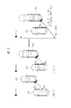
- FIG. 2 is an explanatory diagram illustrating an operation of the detection device in FIG. 1.
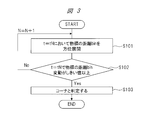
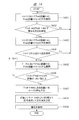
- 3 is a flowchart illustrating an example of an operation process performed by the detection device in FIG. 1.
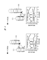
- FIG. 4 is an explanatory diagram of a strong reflection signal of an object, a signal intensity of a reflection point between a strong reflection point and a corner of the object, and an azimuth.
- FIG. 4 is an explanatory diagram illustrating another example of the detection device in FIG. 1.
- 6 is a flowchart illustrating an example of a detection process performed by the detection device of FIG.
- FIG. 4 is an explanatory diagram showing an example of reception strength in a millimeter wave radar having a wide-angle antenna for a BSD application, studied by the present inventors.
- FIG. 9 is an explanatory diagram of an FFT spectrum in the verification experiment of FIG.
- FIG. 4 is an explanatory diagram illustrating a relationship between the amount of spectral leakage power of a reflected signal and the intensity of a reflected signal.
- FIG. 9 is an explanatory diagram illustrating an example of a configuration of a detection device according to a second embodiment. It is explanatory drawing of operation
- FIG. 11 is an explanatory diagram illustrating an example of a configuration of a detection device according to Embodiment 3. It is explanatory drawing of operation
- 16 is a flowchart illustrating an example of a detection process performed by the detection device of FIG.
- FIG. 16 is a flowchart illustrating an example of a detection process when a new switch and a transmission antenna are provided in the detection device in FIG. 15.
- FIG. 13 is an explanatory diagram illustrating an example of a configuration in a detection device according to a fourth embodiment.
- 21 is a flowchart illustrating an example of a detection process performed by the detection device of FIG. 20.
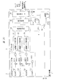
- FIG. 1 is an explanatory diagram illustrating an example of a configuration of the detection device 1 according to the first embodiment.
- the transmission / reception antenna / analog section 2 includes a frequency generator VCO, a transmission antenna TXANT1, N reception antennas RXANT1 to RXANTN forming N reception channels, N frequency mixers MIX1 to MIXN, and N analog / It has digital converters ADC1 to ADCN. Note that the receiving antennas RXANT1 to RXANTN are arranged at intervals where a phase difference occurs in the reception signals between the respective reception channels in order to detect the orientation of the object.
- the modulated signal generated by the frequency generator VCO is distributed to the transmitting antenna TXANT1 and the frequency mixers MIX1 to MIXN.
- the modulation signal is, for example, a signal in the 79 GHz band in the case of a millimeter wave radar.
- the transmitting antenna TXANT1 which is the first transmitting antenna, radiates the modulated signal output from the frequency generator VCO into space as a radio wave.
- the radiated radio wave hits the object, and a part of the reflected radio wave is received by the receiving antennas RXANT1 to RXANTN of the detection device 1.
- the received signals received by the receiving antennas RXANT1 to RXANTN are converted into low-frequency signals by the frequency mixers MIX1 to MIXN and sent to the analog / digital converters ADC1 to ADCN.
- the low frequency signals converted by the frequency mixers MIX1 to MIXN include frequency components corresponding to the distance between the detection device 1 and the target.
- the low-frequency signals are converted into digital signals by the analog / digital converters ADC1 to ADCN, respectively, and then sent to the digital signal processing unit 3.
- the digital signal processing unit 3 includes distance peak detecting units 31 to 3N, an azimuth detecting unit 34, and a corner detecting unit 35.
- the distance peak detection units 31 to 3N constituting the calculation unit perform, for example, FFT (Fast Fourier Transform) processing on the signals converted into digital signals by the analog / digital converters ADC1 to ADCN of the transmitting / receiving antenna / analog unit 2. To convert from a time domain signal to a frequency domain signal.
- FFT Fast Fourier Transform
- power intensity and phase information at a frequency proportional to the distance of the target object from the detection device 1 is extracted from the converted frequency domain signal, and the power intensity and phase information at the extracted frequency are output to the azimuth detecting unit 34.
- the azimuth detecting unit 34 constituting the calculating unit is based on the power intensity and the phase information at the frequencies generated by the distance peak detecting units 31 to 3N, for example, by using signal processing of DBF (Digital Beam Forming).
- DBF Digital Beam Forming
- the corner detecting unit 35 determines the corner of the object based on the information on the distance and the direction of the object output from the direction detecting unit 34 and the information on the distance and the direction of the object at each time stored in the memory 4. It is determined whether or not the object exists, and when a corner of the object is detected, a corner detection signal is output.
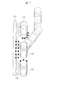
- FIG. 7 is an explanatory diagram showing an example of a verification experiment for each scene of parallel automatic parking by the present inventor.
- FIG. 8 is an explanatory diagram showing an example of the reception intensity in a millimeter wave radar having a wide-angle antenna for a BSD (Blind Spot Detection) application studied by the present inventors.
- the inventors conducted a verification experiment for each scene of parallel automatic parking shown in FIG. 7 in order to realize an automatic parking application using a millimeter wave radar.
- a wall 105 is provided on the left side, and a curb 106 is provided on the right side.
- the vehicles 101 and 102 are parked in parallel along the curb 106 with a parking space for one vehicle.
- An example is shown in which the own vehicle 100 is automatically parked between the vehicle 101 and the vehicle 102.
- a radio wave transmitted from the radar is perpendicular to the target vehicle 101 as shown by a solid line in FIG. Is strongly received at the distance position R0.
- the signals at the distance positions R1 to R5 incident from an angle other than the perpendicular shown by the dotted line in FIG. 8 cause specular reflection, and the reception intensity is reduced.
- the specular reflection becomes stronger as the incident angle becomes acute, the reception power becomes very small at the corner of the target vehicle 101 to be detected, that is, at the distance position R5 shown in FIG. 8, and the vehicle 100 of the own vehicle moves backward. If the corner of the target vehicle 101 does not approach the distance position R0, it is difficult to detect.
- FIG. 9 is an explanatory diagram of the FFT spectrum in the verification experiment of FIG.
- the received signal from the distance position R0 where the reflection intensity is strong also affects the received signals at the distance positions R1 to R5 due to spectrum leakage due to the window function at the time of the FFT processing. This makes corner detection of the vehicle 101 more difficult.
- the distance intervals between the distance positions R0 to R1, the distance positions R1 to R2,... are determined by the resolution of the FFT.
- the received signal from the distance position R0 having a high reflection intensity also affects the received signals at the distance positions R1 to R5 due to spectral leakage due to the window function during the FFT processing.
- the distance between the distance position R0 where the reflection intensity is strong and the distance position where the corner of the target vehicle 101 is located is not buried in the spectral leakage power at the distance position R0. It has been found that there is a signal at a distance position larger than the noise floor.
- FIG. 10 is an explanatory diagram showing the relationship between the amount of spectral leakage power of the reflected signal and the intensity of the reflected signal.
- FIG. 10 shows a comparison result between the amount of spectral leakage power of the reflected signal from the distance position R0 in FIG. 8 and the intensity of the reflected signal from the distance position R4.
- the spectral leakage power at the distance position R0 decreases as the distance bin increases, and at the distance bin at the distance position R4, the spectral leakage power decreases by about 10 dB from the spectral leakage power at the distance position R0. It was confirmed that the azimuth of the position R4 could be detected.
- the detection technique in the detection device 1 is based on this finding.
- FIG. 2 is an explanatory diagram illustrating the operation of the detection device 1 of FIG.
- FIG. 3 is a flowchart illustrating an example of an operation process performed by the detection device 1 in FIG. Note that the flowchart shown in FIG. 3 mainly shows a process in which the digital signal processing unit 3 included in the detection device 1 mainly operates.
- the automatic vehicle 100 starts parking processing.
- the detection device 1 transmits, in other words, radiates radio waves toward the target vehicle 101, and reflects the reflected waves from the target vehicle 101 by the reception antennas RXANT1 to RXANTN of the detection device 1. Receive.
- the received signal is frequency-converted and converted into a digital signal by the transmission / reception antenna / analog unit 2 of the detection device 1 and output to the digital signal processing unit 3.
- This digital signal is subjected to FFT processing by the distance peak detection units 31 to 3N of the digital signal processing unit 3 to obtain a frequency proportional to the distance of the object from the detection device 1, and power intensity and phase information at the frequency. Extract.
- the power intensity and the phase information at the frequency are output to the azimuth detecting unit 34.
- the azimuth detecting unit 34 uses the DBF processing based on the power intensity and the phase information at the frequency generated by the distance peak detecting units 31 to 3N, and uses the DBF processing to determine the distance R0 where the reflection intensity is strong and the distance where the corner of the target vehicle 101 is located.
- the information of the distance and the direction of the position R4 is obtained (Step S101).
- the angle ⁇ R4 2 °.
- the azimuth detecting unit 34 outputs information on the distance and the azimuth of the distance position R4 of the target vehicle 101 to the memory 4 and the corner detecting unit 35, respectively.
- the threshold value is externally input from, for example, an ECU (Electronic Control Unit) that controls the automatic driving of the vehicle 100.
- ECU Electronic Control Unit
- What is stored in the memory 4 in advance may be obtained.
- step S101 If the fluctuation amount is smaller than the threshold value, the process returns to step S101 again (step S102). In the case of the example of FIG. 2, since the variation of the angle ⁇ R4 is equal to or less than the threshold, the process returns to step S101 again.
- the object in the 2 ° azimuth which has been calculated as the azimuth of the distance position R4 until time t1 ⁇ t ⁇ tN, changes from the corner of the target vehicle 101 to the wall 105, so the 2 ° azimuth distance position R4 Changes to another distance position.
- the threshold value of the variation amount may be the variation amount of the azimuth of a certain noted distance position, the variation amount of the distance in a certain noted azimuth, or both.
- the detection device 1 can quickly detect the rear corner of the target vehicle 101 by determining from the time variation of the distance position and the azimuth of the target vehicle 101.
- the low-cost detection device 1 can be provided.
- FIG. 4 is an explanatory diagram of a strong reflection signal of an object, a signal intensity of a reflection point between a strong reflection point and a corner of the object, and an azimuth.
- FIG. 4 shows the results of an experiment conducted to confirm the effectiveness of the detection device 1 of FIG.
- the azimuth of the distance R4 between the distance position R0 where the reflection intensity is strong and the distance position where the corner of the target vehicle 101 is located is calculated to be ⁇ 15 °.
- the azimuth of the distance position R4 was calculated to be + 30 °.
- the corner detection unit 35 determines that the threshold value has been exceeded twice or more, the corner detection unit 35 detects the corner of the target vehicle 101, so that there is an influence of noise such as disturbance. In this case, it is possible to accurately detect the corner of the target vehicle 101.
- FIG. 5 is an explanatory diagram showing another example of the detection device 1 of FIG.
- FIG. 6 is a flowchart illustrating an example of a detection process performed by the detection device of FIG.
- switches SW1 and SW2 and a transmission antenna TXANT2 are newly provided in the transmission / reception antenna / analog unit 2.
- the switch SW1 switches the connection between the frequency generator VCO and the transmission antenna TXANT1.
- the switch SW2 switches the connection between the frequency generator VCO and the transmission antenna TXANT2.
- the switches SW1 and SW2 switch connection destinations based on a corner detection signal output from the corner detection unit 35.
- the transmitting antenna TXANT2 as the second transmitting antenna is an antenna having a tilt angle characteristic of a downward depression angle, for example, and is an antenna specialized for detecting the curb 106 shown in FIG.
- FIG. 6 is a flowchart showing an example of a detection process by the detection device of FIG.
- the processing of steps S201 to S203 in the flowchart of FIG. 6 is the same as the processing of steps S101 to S103 in the flowchart of FIG.
- the transmission antenna TXANT1 and the frequency generator VCO are connected by the switch SW1 until the corner of the target vehicle 101 is detected (steps S201 to S203), that is, until time t ⁇ tN. ing.
- the transmission antenna TXANT2 has, for example, a downward tilt angle characteristic of a depression angle, and is an antenna specialized in detecting the curb 106.
- the transmitting antenna TXANT2 is used to detect a changed distance in the azimuth of interest, for example, the curb 106 located at the distance position R14 in FIG. 2 (step S204). If the curb 106 is not detected in the process of step S204, the process may return to step S201.
- the corner position of the target vehicle 101 can be determined with higher accuracy.
- FIG. 11 is an explanatory diagram illustrating an example of a configuration of the detection device 1 according to the second embodiment.
- a detection device 1 shown in FIG. 11 is different from the detection device 1 shown in FIG. 1 of the first embodiment in the configuration of the digital signal processing unit 3. Other configurations are the same as those in FIG.
- the digital signal processing unit 3 includes distance peak detecting units 31 to 3N, azimuth detecting unit 34, corner detecting unit 35, and newly provided surface detecting unit 36.
- the distance peak detection units 31 to 3N convert the signals converted into digital signals by the analog / digital converters ADC1 to ADCN of the transmitting / receiving antenna / analog unit 2 from time domain signals to frequency domain signals by, for example, FFT processing.
- a frequency proportional to the distance of the object from the detection device 1 and power intensity and phase information at the frequency are extracted from the frequency domain signal, and the power intensity and phase information at the frequency are output to the azimuth detecting unit 34.
- the azimuth detecting unit 34 detects the azimuth where the target object is present using, for example, signal processing of a DBF based on the power intensity and the phase information at the frequency generated by the distance peak detecting units 31 to 3N, The azimuth information is output to the memory 4 and the plane detection unit 36.
- the surface detection unit 36 It is determined whether or not the surface of the target is configured, and when it is determined that the target forms the surface of the same target, a determination result signal is output to the corner detection unit 35.
- the corner detection unit 35 Upon receiving the determination result signal from the plane detection unit 36, the corner detection unit 35 outputs the information on the distance and the azimuth of the object output from the azimuth detection unit 34 and the distance and time of the object stored in the memory 4 with respect to time. Based on the azimuth information, it is determined whether or not there is a corner of the object, and when a corner is detected, a corner detection signal is output.
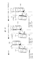
- FIG. 12 is an explanatory diagram of the operation of the detection device 1 of FIG.
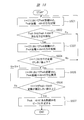
- FIG. 13 is a flowchart illustrating an example of a detection process by the detection device 1 in FIG. Note that the processing in the flowchart in FIG. 13 is mainly performed by the operation of the digital signal processing unit 3.
- the detection device 1 transmits a radio wave toward the target vehicle 101, and receives reflected waves from the target vehicle 101 by the reception antennas RXANT1 to RXANTN of the detection device 1.
- reception signals received by the reception antennas RXANT1 to RXANTN are frequency-converted and converted into digital signals by the transmission / reception antenna / analog unit 2 constituting the detection device 1, and output to the digital signal processing unit 3.
- This digital signal is subjected to FFT processing by the distance peak detectors 31 to 3N included in the digital signal processor 3, and thereafter, a frequency proportional to the distance of the object from the detector 1 and power intensity and phase information at the frequency are extracted. I do.
- the power intensity and phase information at the extracted frequency are output to the azimuth detecting unit 34.
- the azimuth detecting unit 34 uses the DBF processing based on the power intensity and the phase information at the frequency generated by the distance peak detecting units 31 to 3N to obtain information on the distance and azimuth of the distance position R0 where the reflection intensity is strong, and the reflection intensity.
- Information on the distance position R4 which is the distance between the strong distance position R0 and the distance position where the corner of the target vehicle 101 is located, and the azimuth information are acquired (step S301).
- step S302 when there is no difference between the azimuth of the distance position R0 having the strong reflection intensity and the azimuth of the distance position R4 (step S302), two or more reflection points can be detected from the target vehicle 101 as the target. If no, the process returns to step S301. Alternatively, the flow of the automatic parking may be stopped or restarted.
- step S302 If there is a difference between the azimuth of the distance position R0 where the reflection intensity is strong and the azimuth of the distance position R4 (step S302), it is determined that two or more reflection points can be detected from the target vehicle 101, and the distance position R0 is detected. , R4 are output to the memory 4 and the corner detector 35.
- the distance position R0 and the distance position R4 are elements constituting the surface of the same object, as shown in FIG. 12, the trajectories of the distance position R0 and the distance position R4 over time are arranged on a certain straight line. Will be.
- step S305 If the amount of change is smaller than the threshold, the process returns to step S305. In the example of FIG. 12, since the variation of the angle ⁇ R4 is equal to or less than the threshold, the process returns to step S305 again.
- the threshold value is input from the outside, such as an ECU that controls the automatic driving of the vehicle 100.
- the memory 4 may be obtained.
- the distance position R4 in FIG. 12 (step S307).
- the object in the azimuth of 2 ° which has been calculated as the azimuth of the distance position R4 until time t1 ⁇ t ⁇ tN, changes from the corner of the target vehicle 101 to the wall 105 or the curb, so the distance of the azimuth of 2 °
- the position R4 changes to another distance position.
- the threshold value of the variation amount may be the variation amount of the azimuth at a certain distance position of interest, or may be the variation amount of the distance in a certain attention direction. Alternatively, both may be used.
- step S306 when the processing of step S306 by the above-described corner detection unit 35 is performed a plurality of times, that is, when the threshold value is continuously exceeded by the corner detection unit 35 twice or more, It is possible to more accurately detect the corner of the vehicle 101 even when there is an influence of noise such as disturbance due to the determination as the corner of the target vehicle 101.
- the detection device 1 may have a configuration in which the switches SW1 and SW2 and the transmission antenna TXANT2 shown in FIG. 5 of the first embodiment of the present invention are newly provided in the configuration of the detection device 1 of FIG.
- connection configuration of the newly provided switches SW1 and SW2 and the transmission antenna TXANT2 is the same as that of FIG.
- the transmission antenna TXANT2 is also an antenna having a tilt angle characteristic of a downward depression angle, and is an antenna specialized for detecting the curb 106 in FIG.
- FIG. 14 is a flowchart showing an example of a detection process in a detection device in which new switches SW1 and SW2 and a transmission antenna TXANT2 are provided in the detection device 1 of FIG.
- steps S401 to S407 in the flowchart of FIG. 14 is the same as the processing of steps S301 to S307 in the flowchart of FIG.
- the transmission antenna TXANT1 and the frequency generator VCO are connected by the switch SW1 until the detection device 1 detects the corner of the target vehicle 101 (steps S401 to S407), that is, until time t ⁇ tN.
- the transmission antenna TXANT2 has, for example, a downward depression tilt angle characteristic, and is an antenna specialized for detecting the curb 106.
- the distance after the change in the azimuth of interest using the transmitting antenna TXANT2, for example, the wall 105 located at the distance position R14 in FIG. 2 is detected (step S409).
- FIG. 15 is an explanatory diagram illustrating an example of a configuration of the detection device 1 according to the third embodiment.
- the detection device 1 shown in FIG. 15 differs from the detection device 1 of FIG. 11 of the second embodiment in that a threshold value adjustment unit 37 is newly provided in the digital signal processing unit 3.
- the surface detection unit 36 determines whether the target object forms a surface of the same target, calculates the inclination of the surface, and sends the calculation result to the threshold adjustment unit 37 as inclination information. Output.
- This tilt information is correction information.
- a threshold value set in advance is input to the surface detection unit 36.
- This threshold value is obtained by being input from outside such as an ECU that controls the automatic driving of the vehicle 100.
- what is stored in the memory 4 in advance may be obtained.
- Other configurations are the same as those in FIG.
- the threshold adjustment unit 37 calculates a correction threshold corrected in accordance with the inclination information output from the surface detection unit 36 and outputs the calculated correction threshold to the corner detection unit 35.
- FIG. 16 is an explanatory diagram of the operation in the detection device 1 of FIG.
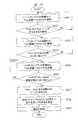
- FIG. 18 is a flowchart illustrating an example of a detection process by the detection device 1 in FIG.
- the processing shown in the flowchart of FIG. 18 is mainly performed by the digital signal processing unit 3.
- the automatic parking process starts.
- the detection device 1 transmits a radio wave toward the target vehicle 101, and receives reflected waves from the target vehicle 101 with the reception antennas RXANT1 to RXANTN of the detection device 1.
- the target vehicle 101 is parked at an inclination of, for example, about 5 °, and the vehicle moves at a speed of about 10 km / h.
- reception signals received by the reception antennas RXANT1 to RXANTN are frequency-converted and converted into digital signals by the transmission / reception antenna / analog unit 2 included in the detection device 1, and output to the digital signal processing unit 3.
- This digital signal is subjected to FFT processing by the distance peak detection units 31 to 3N included in the digital signal processing unit 3 to extract a frequency proportional to the distance of the object from the detection device 1 and power intensity and phase information at the frequency. Then, the power intensity and phase information at the extracted frequency are output to the azimuth detecting unit 34.
- the azimuth detecting unit 34 uses the DBF process to obtain information on the distance and azimuth of the distance position R0 where the reflection intensity is strong and the reflection intensity based on the power intensity and the phase information at the frequencies generated by the distance peak detection units 31 to 3N.
- Information on the distance and azimuth of the distance R4 between the strong distance position R0 and the distance position where the corner of the target vehicle 101 is located is acquired (step S501).
- step S502 when there is no difference between the azimuth of the distance position R0 having the strong reflection intensity and the azimuth of the distance position R4 (step S502), two or more reflection points are detected from the target vehicle 101 as the target. As a result, the process returns to step S501. Alternatively, the automatic parking process may be stopped or the detection device 1 may be restarted.
- step S502 If there is a difference between the azimuth of the distance position R0 where the reflection intensity is strong and the azimuth of the distance position R4 (step S502), it is determined that two or more reflection points can be detected from the target vehicle 101 and the distance between the distance positions R0 and R4. And the azimuth information are output to the memory 4 and the corner detector 35.
- the distance position R0 and the distance position R4 are elements constituting the surface of the same object, as shown in FIG. 16, the trajectories of the distance position R0 and the distance position R4 over time are arranged on a certain straight line. Will be.
- FIG. 17 is an explanatory diagram showing the relationship between the distance and the azimuth at each time of distance positions R0 and R4 between the vehicle 100 of the host vehicle and the target vehicle 101.
- the graph of FIG. 17A shows the distance at each time of the distance positions R0 and R4 in a state in which the own vehicle 100 and the target vehicle 101 are arranged with an inclination of about 5 °. is there.
- the graph of FIG. 17B shows the azimuth of each of the distance positions R0 and R4 in a state where the own vehicle 100 and the target vehicle 101 are arranged with an inclination of about 5 °. Things.
- the surface detection unit 36 and the corner detection unit 35 need to consider the amount of change in the distance and azimuth of the target object, that is, the distance of the vehicle 101 due to the inclination.
- a threshold value according to the inclination is input.
- the threshold value of the azimuth fluctuation is a numerical value obtained by adding a fluctuation margin due to noise to 0.2 °.
- Information on the inclination between the own vehicle 100 and the target vehicle 101 detected by the surface detection unit 36 is output to the threshold adjustment unit 37.
- the threshold adjuster 37 calculates a corrected threshold which is a threshold corrected according to the inclination information, and outputs the corrected threshold to the corner detector 35.
- step S505 If the amount of change is smaller than the correction threshold, the process returns to step S505 again. In the example of FIG. 16, since the variation of the angle ⁇ R4 is equal to or smaller than the correction threshold, the process returns to step S505.
- the threshold value of the variation amount may be the variation amount of the azimuth of a certain noted distance position, the variation amount of the distance in a given noted azimuth, or both.
- the automatic parking process can be performed with high accuracy.
- step S506 when the processing of step S506 by the corner detection unit 35 is performed a plurality of times, that is, when the correction threshold value is determined by the corner detection unit 35 more than once, the corner of the target vehicle 101 is determined.
- the determination makes it possible to more accurately detect the corner of the vehicle 101 even when there is an influence of noise such as disturbance.
- the newly provided transmitting antenna TXANT2 is an antenna having a downward depression angle tilt angle characteristic, and is an antenna specialized for detecting the curb 106 and the like in FIG.
- FIG. 19 is a flowchart illustrating an example of a detection process in a detection device provided with new switches SW1 and SW2 and a transmission antenna TXANT2.
- steps S601 to S607 in the flowchart of FIG. 19 is the same as the processing of steps S501 to S507 in the flowchart of FIG.
- the transmitting antenna TXANT1 and the frequency generator VCO are connected by the switch SW1 until the detection device 1 detects the corner of the target vehicle 101 (steps S601 to S607), that is, until time t ⁇ tN.
- the transmission antenna TXANT2 has, for example, a downward depression tilt angle characteristic, and is an antenna specialized for detecting the curb 106.
- the distance after the change in the azimuth of interest, for example, the curb 106 shown in FIG. 7 is detected using the transmitting antenna TXANT2 (step S609).
- the automatic parking process is performed using the information of the free spot 160 detected before the automatic parking process is started.
- the technique to be performed will be described.
- the free spot 160 is information on an area where the vehicle 100 of the vehicle can be parked.
- the free spot 160 is a parking space between the vehicle 101 and the vehicle 102 as indicated by a dotted frame.
- the target vehicle 101 is moved at the timing when the own vehicle 100 enters the automatic parking process. It may be moving back and forth. Therefore, it is necessary to recognize the corner of the target vehicle 101 from the side.
- FIG. 20 is an explanatory diagram illustrating an example of a configuration of the detection device 1 according to the fourth embodiment.
- the detection device 1 shown in FIG. 20 is different from the detection device 1 shown in FIG. 11 of the second embodiment in that a new memory 4a is provided.
- This memory 4a stores the distance and direction of the corner of the target vehicle 101 detected by the free spot detection.
- the information on the distance and direction of the corner of the target vehicle 101 based on the detection of the free spot is information obtained from, for example, an externally connected sensor.
- the information may be information detected by the detection device 1.
- the corner detecting unit 35 outputs the information on the distance and the azimuth of the object output from the azimuth detecting unit 34, the information on the distance and the azimuth of the object stored in the memory 4 for each time, and the free information stored in the memory 4a. Based on the information on the distance and orientation of the object obtained by the spot detection, it is determined whether or not a corner of the object exists, and a corner detection signal is output when the corner of the object is detected.
- FIG. 21 is a flowchart showing an example of the detection process by the detection device 1 of FIG.
- step S707 the distance and the azimuth of the distance position R4 of the target vehicle 101 are detected, and the target vehicle 101 is detected as a free spot based on the corner position information of the target vehicle 101 stored in the memory 4a. It is checked whether the user has moved back and forth later (step S707).
- step S708 If the result of the corner detection of the target vehicle 101 obtained by the above-described sensor free spot detection matches the result of the corner detection by the corner detection unit 35, the target vehicle 101 has not moved after the free spot detection. Is determined (step S708), and the process of automatic parking proceeds.
- the automatic parking process is stopped.
- the safety can be confirmed from the positional relationship between the target vehicle 101 and the vehicle 102 located behind the vehicle 101 shown in FIG. 7, the automatic parking process may proceed as it is.
- the automatic parking correction process can be performed by reconfirming the position of the corner of the target vehicle 101 by the detection device 1.
- the automatic parking process can be safely advanced or stopped.
Landscapes
- Engineering & Computer Science (AREA)
- Radar, Positioning & Navigation (AREA)
- Remote Sensing (AREA)
- Physics & Mathematics (AREA)
- Computer Networks & Wireless Communication (AREA)
- General Physics & Mathematics (AREA)
- Electromagnetism (AREA)
- Radar Systems Or Details Thereof (AREA)
- Traffic Control Systems (AREA)
Abstract
検知装置1において、送信アンテナTXANT1は、変調信号を空間に放射する。受信アンテナRXANT1~RXANTNは、送信アンテナTXANT1から放射された変調信号の反射波を受信する。算出部は、距離ピーク検知部31~3Nおよび方位検知部34を備え、受信アンテナRXANT1~RXANTNが受信した反射波の受信信号から対象物の距離および方位を一定時間毎に取得して、取得した対象物の距離および方位から距離の時間的変化量を算出する。コーナ検出部35は、算出部が算出する時間的変化量から対象物のコーナを検知する。このコーナ検出部は、算出部が算出する時間的変化量と予め設定されるしきい値とを比較して、時間的変化量がしきい値を超えた際に対象物のコーナを検知してコーナ検知信号を出力する。
Description
本発明は、検知装置に関し、特に、レーダシステムによる対象物におけるコーナ部分の検知に有効な技術に関する。
自動車を運転するドライバの負荷低減および事故率を低減する技術として、運転支援システムが注目を集めている。この運転支援システムの1つとして、自動駐車支援システムがある。
この自動駐車支援システムは、駐車スペースを検知して目標駐車位置に隣接車両と適切な距離を確保しながら区画線内へクルマを誘導して自動的に自動車を駐車させるシステムである。
近年、ミリ波レーダの性能向上に伴い、ミリ波レーダが元来用いられていた遠距離の検知だけでなく、中距離、あるいは短距離についても、その応用が進められており、ミリ波レーダは、自動駐車アプリケーションを実現するために、自動駐車の際のターゲット車両のコーナ部などを検知する検知装置に用いられている。
この種のレーダ装置を用いた検知装置による検知技術としては、例えばミリ波レーダにより自車両前方の物体を検知する場合に複数の物体に跨る反射点群を1つの物体として判断するなどの誤ったグルーピング処理を防止するために、複数の反射点の右端認識点、左端認識点、および代表認識点を算出し、それぞれの変化量に基づいて算出した物体の推定幅を用いてグルーピング処理を行うものが知られている(例えば特許文献1参照)。
しかしながら、上述した特許文献1の技術では、物標が同一物か否かを認識点の時間変化量にて判定しているが、物体のそれぞれコーナである右端認識点および左端認識点の算出の仕方については記載されていない。
また、自動駐車にて縦列駐車や並列駐車を行う際には、ターゲット車両のコーナ部を迅速に且つ正確に抽出する必要がある。特許文献1の場合、右端認識点は、グルーピング範囲内の反射点のうち、左右方向で最も右端に位置するものを該右端認識点としているが、これでは、物体のコーナであるか否かを判断することができない。言い換えれば、ターゲット車両のコーナ部を検知することができず、自動駐車の精度が低下してしまう恐れがある。
また、上述したミリ波レーダを用いたターゲット車両におけるコーナ部などを検知する技術としては、ミリ波レーダの送信ビームフォーミングにてビーム走査を行うことにより、ターゲット車両のコーナ部を検知することが考えられる。
しかしながら、この場合、送信ビームフォーミングを行うための移相器などが新たに必要となり、さらには送信アンテナの数も増加してしまうことになる。その結果、検知装置のコストが大きくなってしまうという問題がある。
本発明の目的は、自動駐車アプリケーションにおいて対象物のコーナを迅速かつ安価に検知することのできる技術を提供することにある。
本発明の前記ならびにその他の目的と新規な特徴については、本明細書の記述および添付図面から明らかになるであろう。
本願において開示される発明のうち、代表的なものの概要を簡単に説明すれば、次のとおりである。
すなわち、代表的な検知装置は、第1の送信アンテナ、複数の受信アンテナ、算出部、およびコーナ検出部を有する。第1の送信アンテナは、変調信号を空間に放射する。複数の受信アンテナは、第1の送信アンテナから放射された変調信号の反射波を受信する。
算出部は、複数の受信アンテナが受信した反射波の受信信号から対象物の距離および方位を一定時間毎に取得して、取得した対象物の距離および方位から距離の時間的変化量を算出する。
コーナ検出部は、算出部が算出する時間的変化量から対象物のコーナを検知する。このコーナ検出部は、算出部が算出する時間的変化量と予め設定されるしきい値とを比較して、時間的変化量がしきい値を超えた際に対象物のコーナを検知して、対象物のコーナを検知したことを示すコーナ検知信号を出力する。
特に、コーナ検出部は、時間的変化量がしきい値を超えた時間の前に算出部が算出した距離および方位に対応する対象物の点を対象物のコーナとして検出する。
本願において開示される発明のうち、代表的なものによって得られる効果を簡単に説明すれば以下のとおりである。
低コストで検出時間が短い検知装置を提供することができる。
実施の形態を説明するための全図において、同一の部材には原則として同一の符号を付し、その繰り返しの説明は省略する。
(実施の形態1)
以下、実施の形態を詳細に説明する。
以下、実施の形態を詳細に説明する。
〈検知装置の構成例〉
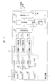
図1は、本実施の形態1による検知装置1における構成の一例を示す説明図である。
図1は、本実施の形態1による検知装置1における構成の一例を示す説明図である。
検知装置1は、図1に示すように。送受信アンテナ/アナログ部2、デジタル信号処理部3、およびメモリ4から構成されている。送受信アンテナ/アナログ部2は、周波数生成器VCO、送信アンテナTXANT1、N個の受信チャンネルを構成するN個の受信アンテナRXANT1~RXANTN、N個の周波数混合器MIX1~MIXN、およびN個のアナログ/デジタル変換器ADC1~ADCNを有する。なお、受信アンテナRXANT1~RXANTNは、対象物の方位を検知するために各受信チャンネル間の受信信号に位相差が生じる間隔にて配置されている。
周波数生成器VCOが生成した変調信号は、送信アンテナTXANT1および周波数混合器MIX1~MIXNにそれぞれ分配される。変調信号は、ミリ波レーダであれば例えば79GHz帯の信号である。
第1の送信アンテナである送信アンテナTXANT1は、周波数生成器VCOから出力される変調信号を空間に電波として放射する。放射された電波は、対象物に当たり、反射した一部の電波が検知装置1の受信アンテナRXANT1~RXANTNにて受信される。
受信アンテナRXANT1~RXANTNにて受信された受信信号は、周波数混合器MIX1~MIXNによって低周波信号に変換されて、アナログ/デジタル変換器ADC1~ADCNに送られる。
周波数混合器MIX1~MIXNによって変換された低周波信号は、検知装置1と対象物との距離に対応した周波数成分を含んでいる。この低周波信号は、アナログ/デジタル変換器ADC1~ADCNによってデジタル信号にそれぞれ変換された後、デジタル信号処理部3に送られる。
デジタル信号処理部3は、距離ピーク検知部31~3N、方位検知部34、およびコーナ検出部35から構成されている。算出部を構成する距離ピーク検知部31~3Nは、送受信アンテナ/アナログ部2のアナログ/デジタル変換器ADC1~ADCNによってデジタル信号に変換された信号を例えばFFT(高速フーリエ変換:Fast Fourier Transform)処理によって時間領域信号から周波数領域信号へ変換する。
そして、変換した周波数領域信号から対象物の検知装置1からの距離に比例する周波数における電力強度および位相情報を抽出して、抽出した周波数における電力強度および位相情報を方位検知部34に出力する。
算出部を構成する方位検知部34は、距離ピーク検知部31~3Nが生成した周波数における電力強度および位相情報に基づいて、例えばDBF(Digital Beam Forming:デジタルビームフォーミング)の信号処理を用いて対象物の存在する方位を検知して、対象物の距離と方位の情報をメモリ4およびコーナ検出部35にそれぞれ出力する。
メモリ4は、方位検知部34から出力された対象物の距離および方位の情報を時間t=t1~t=tNまでの時間毎に格納するとともに、時間毎の対象物の距離および方位の情報をコーナ検出部35に出力する。ここで、時間t=tNのNは、上述した受信チャンネルの数であるNとは異なる。
コーナ検出部35は、方位検知部34から出力された対象物の距離および方位の情報と、メモリ4に格納された対象物の時間毎の距離・方位の情報に基づいて、対象物のコーナが存在するか否かの判定を行い、対象物のコーナを検知した際にコーナ検知信号を出力する。
〈検知装置1の動作原理〉
ここで、検知装置1における動作について説明する。
ここで、検知装置1における動作について説明する。
図7は、本発明者の検討による縦列自動駐車のシーン毎の検証実験の一例を示す説明図である。図8は、本発明者の検討によるBSD(Blind Spot Detection)アプリケーション用の広角アンテナを有するミリ波レーダにおける受信強度の一例を示す説明図である。
まず、発明者らは、ミリ波レーダを用いた自動駐車アプリケーションを実現するため、図7に示す縦列自動駐車のシーン毎の検証実験を行った。
図7では、左側に壁105が有り、その右側には、縁石106が設けられており、該縁石106に沿って車両101と車両102とが車両1台分の駐車スペースを空けて縦列駐車されており、これら車両101と車両102との間に自車の車両100を自動駐車させる例が示されている。
図7において、自動駐車が開始される状態では、自車の車両100が前方に駐車されているターゲット車両である車両101の後部コーナを正確かつ迅速に認識する必要がある。
例えば広角のアンテナを持ったミリ波レーダにてターゲットの車両101の側部を見た場合には、図8の実線にて示すようにレーダから送信された電波がターゲットの車両101に対して垂直に入射する距離位置R0の信号が強く受信される。その一方、図8の点線にて示す垂直ではない角度から入射した距離位置R1~R5の信号は、鏡面反射を起こしてしまい受信強度は低下する。
特に、入射角度が鋭角になるほど鏡面反射が強くなるため、検知したいターゲットの車両101のコーナ、すなわち図8に示す距離位置R5は、受信電力が非常に小さくなり、自車の車両100が後進してターゲットの車両101のコーナが距離位置R0まで近づかないと検知が困難である。
図9は、図8の検証実験におけるFFTスペクトルの説明図である。
この図9のFFTスペクトルに示すとおり、反射強度の強い距離位置R0からの受信信号は、FFT処理の際の窓関数によるスペクトル漏れにより距離位置R1~R5の受信信号にも影響を及ぼし、ターゲットの車両101のコーナ検知をより困難にする。ここで、距離位置R0~R1、距離位置R1~R2、・・・の距離間隔は、FFTの分解能で決まっている。
上述した図9にて説明したとおり、反射強度の強い距離位置R0からの受信信号は、FFT処理の際の窓関数によるスペクトル漏れから距離位置R1~R5の受信信号にも影響を及ぼす。
しかし、本発明者が詳細な検討を行った結果、反射強度の強い距離位置R0とターゲットの車両101のコーナがある距離位置との間の距離に、距離位置R0のスペクトル漏れ電力に埋もれず、かつノイズフロアより大きい距離位置にある信号が存在することを発見した。
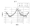
図10は、反射信号のスペクトル漏れ電力の量および反射信号強度の関係を示す説明図である。この図10は、図8における距離位置R0からの反射信号のスペクトル漏れ電力の量と、距離位置R4からの反射信号強度についての比較結果を示したものである。
距離位置R0のスペクトル漏れ電力は、距離binが離れる毎に低下して、距離位置R4の距離binでは、距離位置R0のスペクトル漏れ電力より10dB程度小さくなる結果となり、DBFによる方位検知の結果、距離位置R4の方位を検出できることを確認した。検知装置1における検知技術は、この知見に基づいたものである。
〈検知装置1の動作例〉
以下、検知装置1における動作について、詳細を説明する。
以下、検知装置1における動作について、詳細を説明する。
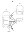
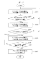
図2は、図1の検知装置1による動作を説明する説明図である。図3は、図1の検知装置1による動作処理の一例を示すフローチャートである。なお、この図3に示すフローチャートは、主に検知装置1が有するデジタル信号処理部3が主体となって動作する処理を示したものである。
まず、図2に示す時間t=t1において、自動の車両100による駐車処理を開始する。この時間t=t1にて、検知装置1は、ターゲットの車両101に向けて、電波を送信、言い換えれば放射して、ターゲットの車両101からの反射波を検知装置1の受信アンテナRXANT1~RXANTNによって受信する。
受信された受信信号は、検知装置1の送受信アンテナ/アナログ部2によって周波数変換およびデジタル信号に変換されて、デジタル信号処理部3へ出力される。このデジタル信号は、デジタル信号処理部3の距離ピーク検知部31~3NによるFFT処理が行われて、対象物の検知装置1からの距離に比例する周波数と、その周波数における電力強度と位相情報を抽出する。周波数における電力強度と位相情報とは、方位検知部34に出力される。
方位検知部34は、距離ピーク検知部31~3Nが生成した周波数における電力強度と位相情報とに基づいて、DBF処理を用いて反射強度の強い距離位置R0とターゲットの車両101のコーナがある距離位置R4の距離と方位の情報を取得する(ステップS101)。ここで、図2に示す例の場合には、角度∠R4=2°である。
方位検知部34は、ターゲットの車両101の距離位置R4の距離および方位の情報をメモリ4およびコーナ検出部35へそれぞれ出力する。メモリ4は、方位検知部34から出力されたターゲットの車両101の距離位置R4の時間t=t1における距離および方位の情報を格納する。
次の時間t=t2についても同様の信号処理を行い、時間t=t2におけるターゲットの車両101の距離位置R4の距離および方位の情報をメモリ4およびコーナ検出部35へ出力する。図2に示す例では、方位の情報は、角度∠R4=2°である。
コーナ検出部35は、時間t=t1における距離位置R4の距離および方位の情報と、時間t=t2における距離位置R4の距離および方位の情報とを比較して、両者の変動量がある一定のしきい値になっているか否かを判定する。
このしきい値は、例えば車両100における自動運転の制御を司るECU(Electronic Control Unit)などから外部入力される。あるいは、予めメモリ4に格納したものを取得するようにしてもよい。
変動量がしきい値より小さい場合は、再度ステップS101の処理に戻る(ステップS102)。図2の例の場合、角度∠R4の変動量がしきい値以下のため、再度ステップS101の処理に戻る。なお、時間t=t1と時間t=t2との時間間隔は、距離および方位を算出する処理時間に依存し、その処理時間は、ミリ波レーダの場合、概ね数10msのオーダである。
時間t=tNにおいても同様の信号処理を行い、時間t=tNにおけるターゲットの車両101の距離位置R4の距離および方位の情報をメモリ4およびコーナ検出部35へそれぞれ出力する。図2の例の場合には、角度∠R4=45°である。
コーナ検出部35は、時間t=t1,t2=,…tN-1における距離位置R4の距離および方位の情報と、時間t=tNおける距離位置R4の距離および方位の情報とを比較して、両者の変動量が設定されたしきい値を超えているか否かを判定し、変動量がしきい値より大きい場合は、その距離位置にコーナがあると判断する(ステップS103)。図2の例の場合には、時間t=tNにおいて、角度∠R4の変動量が43°となり、しきい値を超える。
より正確には、時間t=tN-1における距離位置R4の距離および方位がターゲットの車両101のコーナ位置を示す。また、時間t1<t<tNまで距離位置R4の方位として算出されていた2°の方位にある対象物は、ターゲットの車両101のコーナから壁105へ変化するため、2°方位の距離位置R4は、別の距離位置に変化する。図2の場合は、時間t=tNにおいて、2°方位の距離位置が距離位置R4から距離位置R14に変化する。このため、変動量のしきい値は、ある注目した距離位置の方位の変動量としても、ある注目した方位における距離の変動量としても、もしくはその両者としてもよい。
以上の処理により、検知装置1では、ターゲットの車両101の距離位置および方位の時間変動量から判定することにより、迅速にターゲットの車両101の後部のコーナを検知することができる。
また、送信ビームフォーミング技術などを用いることなく、高精度にターゲットの車両101の後部のコーナを検知することができるので、低コストの検知装置1を提供することができる。
〈検知装置1の有効性〉
図4は、対象物の強反射信号、強反射点と対象物のコーナとの間にある反射点の信号強度、および方位についての説明図である。
図4は、対象物の強反射信号、強反射点と対象物のコーナとの間にある反射点の信号強度、および方位についての説明図である。
この図4は、図1の検知装置1における有効性を確認するために行った実験結果を示したものである。
図4の左側に示す時間t=t2相当の時間において、反射強度の強い距離位置R0とターゲットの車両101のコーナがある距離位置との間の距離R4の方位は-15°と算出された。
一方、図4の右側に示すターゲットの車両101のコーナまでの距離と距離位置R4が一致する時間t=tN相当の時間において、距離位置R4の方位は、+30°と算出された。
つまり、時間t=t2から時間t=tNまで距離位置R4の方位が45°変化していることが確認でき、検知装置1にてターゲットの車両101の後部のコーナを検知できることを確認した。
なお、時間t=tNにおける距離位置R4の方位が30°となっている理由は、反射強度の強い距離位置R0からのスペクトル漏れが距離位置R4まで影響を与えており、その距離位置R0の方位を算出しているためである。
また、より好適な実施形態としては、コーナ検出部35が2回以上しきい値を超えたと判定した際にターゲットの車両101のコーナと検知することにより、外乱などの雑音の影響があった場合においても正確にターゲットの車両101のコーナを検知することが可能となる。
〈検知装置の他の構成例および動作例〉
図5は、図1の検知装置1の他の例を示す説明図である。図6は、図5の検知装置による検知処理の一例を示すフローチャートである。
図5は、図1の検知装置1の他の例を示す説明図である。図6は、図5の検知装置による検知処理の一例を示すフローチャートである。
図5に示す検知装置1が、図1の検知装置1と異なるところは、送受信アンテナ/アナログ部2にスイッチSW1,SW2および送信アンテナTXANT2が新たに設けられた点である。
スイッチSW1は、周波数生成器VCOと送信アンテナTXANT1との接続を切り替える。スイッチSW2は、周波数生成器VCOと送信アンテナTXANT2との接続を切り替える。これらスイッチSW1,SW2は、スイッチ部となる。
これらスイッチSW1,SW2は、コーナ検出部35から出力されるコーナ検知信号に基づいて、接続先の切り替えが行われる。第2の送信アンテナである送信アンテナTXANT2は、例えば下向きの俯角のチルト角特性を持つアンテナであり、図7に示す縁石106を検知するのに特化したアンテナである。
続いて、図5の検知装置1における動作について説明する。
図6は、図5の検知装置による検知処理の一例を示すフローチャートである。ここで、図6のフローチャートにおけるステップS201~S203の処理は、図3のフローチャートにおけるステップS101~S103と同様の処理である。
図5に示す検知装置1において、ターゲットの車両101のコーナが検出されるまで(ステップS201~S203)、すなわち時間t<tNまでは、スイッチSW1によって送信アンテナTXANT1と周波数生成器VCOとが接続されている。
そして、時間t=tNにおいて、ターゲットの車両101のコーナを検知した際にコーナ検知部35からコーナ検出信号が出力されると、スイッチSW1がオフとなり、スイッチSW2がオンとなる。その結果、送信アンテナTXANT2と周波数生成器VCOとが接続される。
上述したように、送信アンテナTXANT2は、例えば下向き、すなわち俯角のチルト角特性を有しており、縁石106を検知することに特化したアンテナである。時間t=tN+1において、送信アンテナTXANT2を用いて注目した方位における変動後の距離、例えば図2の距離位置R14に配置されている縁石106を検知する(ステップS204)。ステップS204の処理にて、縁石106を検知しない場合には、ステップS201の処理に戻るようにしてもよい。
このように、ターゲットの車両101のコーナを検知した後、縁石106を検知することによって、ターゲットの車両101のコーナ位置をより高精度に判定することが可能となる。
(実施の形態2)
〈検知装置1の構成例〉
図11は、本実施の形態2による検知装置1における構成の一例を示す説明図である。
〈検知装置1の構成例〉
図11は、本実施の形態2による検知装置1における構成の一例を示す説明図である。
図11に示す検知装置1は、前記実施の形態1の図1に示す検知装置1と異なる所は、デジタル信号処理部3の構成である。その他の構成については、図1と同様であるので説明は省略する。
デジタル信号処理部3は、距離ピーク検知部31~3N、方位検知部34、コーナ検出部35、および新たに設けられた面検出部36から構成されている。距離ピーク検知部31~3Nは、送受信アンテナ/アナログ部2のアナログ/デジタル変換器ADC1~ADCNによってデジタル信号に変換された信号を例えばFFT処理によって時間領域信号から周波数領域信号へ変換する。
そして、この周波数領域信号から対象物の検知装置1からの距離に比例する周波数とその周波数における電力強度および位相情報を抽出し、該周波数における電力強度と位相情報を方位検知部34に出力する。
方位検知部34は、距離ピーク検知部31~3Nが生成した周波数における電力強度と位相情報に基づいて、例えばDBFの信号処理を用いて対象物の存在する方位を検知し、対象物の距離と方位の情報をメモリ4および面検出部36に出力する。
メモリ4は、方位検知部34から出力された対象物の距離および方位の情報を時間t=t1~t=tNまでの時間毎に格納するとともに、時間毎の対象物の距離および方位の情報をコーナ検出部35および面検出部36に出力する。ここで、時間t=tNのNは、上述した受信チャンネルの数であるNとは異なる。
面検出部36は、方位検知部34から出力された対象物の距離および方位の情報と、メモリ4に格納された対象物の時間毎の距離・方位の情報に基づいて、対象物が同一物標の面を構成しているかの判定を行い、対象物が同一物標の面を構成していると判定した際に判定結果信号をコーナ検出部35へ出力する。
コーナ検出部35は、面検出部36から判定結果信号を受け取ると、方位検知部34から出力された対象物の距離および方位の情報と、メモリ4に格納された対象物の時間毎の距離・方位の情報を元に対象物のコーナが存在するかの判定を行い、コーナを検知した際にコーナ検知信号を出力する。
〈検知装置1の動作例〉
図12は、図11の検知装置1による動作の説明図である。図13は、図11の検知装置1による検知処理の一例を示すフローチャートである。なお、図13のフローチャートにおける処理の主体は、主にデジタル信号処理部3の動作によるものである。
図12は、図11の検知装置1による動作の説明図である。図13は、図11の検知装置1による検知処理の一例を示すフローチャートである。なお、図13のフローチャートにおける処理の主体は、主にデジタル信号処理部3の動作によるものである。
まず、図12の時間t=t1において自動駐車を開始する。時間t=t1にて検知装置1は、ターゲットの車両101に向けて、電波を送信して、ターゲットの車両101からの反射波を検知装置1の受信アンテナRXANT1~RXANTNによって受信する。
受信アンテナRXANT1~Nによって受信された受信信号は、検知装置1を構成する送受信アンテナ/アナログ部2によって周波数変換およびデジタル信号に変換されてデジタル信号処理部3へ出力される。
このデジタル信号は、デジタル信号処理部3が有する距離ピーク検知部31~3NによってFFT処理された後、対象物の検知装置1からの距離に比例する周波数とその周波数における電力強度と位相情報を抽出する。抽出した周波数における電力強度および位相情報は、方位検知部34に出力される。
方位検知部34は、距離ピーク検知部31~3Nが生成した周波数における電力強度および位相情報に基づいて、DBF処理を用いて反射強度の強い距離位置R0の距離と方位の情報、および反射強度の強い距離位置R0とターゲットの車両101のコーナがある距離位置との間の距離である距離位置R4と方位の情報を取得する(ステップS301)。図12の例では、角度∠R0=45°であり、角度∠R4=2°である。
ここで、反射強度の強い距離位置R0の方位と、距離位置R4の方位とにある差分がない場合は(ステップS302)、対象物となるターゲットの車両101から2箇所以上の反射点を検知できなかったとして、ステップS301の処理に戻る。あるいは、自動駐車のフローを中止もしくは再起動を行うようにしてもよい。
反射強度の強い距離位置R0の方位と、前記距離位置R4の方位とにある差分がある場合は(ステップS302)、ターゲットの車両101から2箇所以上の反射点を検知できたとして、距離位置R0,R4の距離および方位の情報をメモリ4およびコーナ検出部35へ出力する。
メモリ4は、方位検知部34から入力されたターゲットの車両101の距離位置R0の時間t=t1における距離および方位の情報と、距離位置R4の時間t=t1における距離および方位の情報とを格納する。
次の時間t=t2についても同様の信号処理を行い、時間t=t2におけるターゲットの車両101の距離位置R0,R4の距離および方位の情報をメモリ4および面検出部36へ出力する(ステップS303)。図12の例では、角度∠R0=45°であり、角度∠R4=2°である。
面検出部36は、時間t=t1における距離位置R0,R4の距離および方位の情報と、時間t=t2における距離位置R0,R4の距離および方位の情報とに基づいて、距離位置R0と距離位置R4とが同一対象物の面を構成する要素であるかを判定する(ステップS304)。
もし、距離位置R0と距離位置R4とが同一対象物の面を構成する要素であれば、図12に示すとおり、距離位置R0と距離位置R4との各時間による軌跡は、ある直線上に並ぶことになる。
コーナ検出部35は、時間t=tNにおける距離位置R0,R4の距離および方位の情報(ステップS305)と、時間t=t1、t2、…tN-1における距離位置R4の距離および方位の情報とを比較して、両者の変動量がある一定のしきい値を超えているか否かを判定する(ステップS306)。
そして、変動量がしきい値より小さい場合は、ステップS305の処理に戻る。図12の例では、角度∠R4の変動量がしきい値以下のため、再度ステップS305の処理に戻る。
ここでも、しきい値は、例えば車両100における自動運転の制御を司るECUなどの外部から入力される。あるいは、予めメモリ4に格納したものを取得するようにしてもよい。
変動量がしきい値を超えている場合は、その距離位置、図12の距離位置R4にコーナがあると判断する(ステップS307)。図12の例では、時間t=tNにおいて、角度∠R4の変動量が43°となり、しきい値を超える。より正確には、時間t=tN-1における距離位置R4の距離および方位がターゲットの車両101のコーナ位置を示す。
また、時間t1<t<tNまで距離位置R4の方位として算出されていた2°の方位にある対象物は、ターゲットの車両101のコーナから壁105あるいは縁石へ変化するため、2°方位の距離位置R4は、別の距離位置に変化する。
図12の場合は、時間t=tNにおいて2°方位の距離位置が距離位置R4から距離位置R14に変化する。このため、変動量のしきい値は、ある注目した距離位置の方位の変動量としてもよいし、ある注目した方位における距離の変動量としてもよい。もしくはその両者としてもよい。
以上の動作により、時間t=t2において距離位置R0,R4の時間軌跡によって同一対象物の面を構成するかを判定する面検出部36を検知装置1に設けることにより、より正確にターゲットの車両101の後段のコーナ部分を検出することが可能となる。
これにより、自動駐車の精度を向上させることができる。
また、より好適な例としては、上述したコーナ検出部35によるステップS306の処理を複数回、すなわちコーナ検出部35よるしきい値判定にて、2回以上しきい値を連続して超えた場合にターゲットの車両101のコーナと判定することにより、外乱などの雑音の影響があった場合においても、より正確に車両101のコーナを検知することが可能となる。
〈検知装置1の他の構成例および動作例〉
また、検知装置1については、図11の検知装置1の構成に前記発明の実施の形態1の図5に示すスイッチSW1,SW2および送信アンテナTXANT2を新たに設けた構成としてもよい。
また、検知装置1については、図11の検知装置1の構成に前記発明の実施の形態1の図5に示すスイッチSW1,SW2および送信アンテナTXANT2を新たに設けた構成としてもよい。
この場合、新たに設けられたスイッチSW1,SW2および送信アンテナTXANT2の接続構成については、図5と同様であるので説明は省略する。また、送信アンテナTXANT2についても、下向きの俯角のチルト角特性を持つアンテナであり、図7の縁石106などの検知に特化したアンテナである。
図14は、図11の検知装置1に新たなスイッチSW1,SW2および送信アンテナTXANT2を設けた検知装置における検知処理の一例を示すフローチャートである。
ここで、図14のフローチャートにおけるステップS401~S407の処理は、図13のフローチャートにおけるステップS301~S307の処理と同様である。
検知装置1において、ターゲットの車両101のコーナが検出されるまで(ステップS401~S407)、すなわち時間t<tNまでは、スイッチSW1によって送信アンテナTXANT1と周波数生成器VCOとが接続されている。
そして、時間t=tNにおいて、ターゲットの車両101のコーナを検知した際にコーナ検出信号が出力されると、スイッチSW1がオフとなり、スイッチSW2がオンとなる(ステップS408)。その結果、送信アンテナTXANT2と周波数生成器VCOとが接続される。
上述したように、送信アンテナTXANT2は、例えば下向きの俯角チルト角特性を有しており、縁石106を検知することに特化したアンテナである。時間t=tN+1において、送信アンテナTXANT2を用いて注目した方位における変動後の距離、例えば図2の距離位置R14に配置されている壁105の検知する(ステップS409)。
これによっても、ターゲットの車両101のコーナを検知した後、縁石106を検知することによって、ターゲットの車両101のコーナ位置をより高精度に判定することが可能となる。
(実施の形態3)
本実施の形態3では、自車とターゲットの車両101とが水平に並んでおらず、例えばターゲットの車両101がある傾きを持っている場合に、該車両101のコーナを検出するのに好適な例について説明する。
本実施の形態3では、自車とターゲットの車両101とが水平に並んでおらず、例えばターゲットの車両101がある傾きを持っている場合に、該車両101のコーナを検出するのに好適な例について説明する。
〈検知装置1の構成例〉
図15は、本実施の形態3による検知装置1における構成の一例を示す説明図である。
図15は、本実施の形態3による検知装置1における構成の一例を示す説明図である。
図15に示す検知装置1が、前記実施の形態2の図11の検知装置1と異なるところは、デジタル信号処理部3にしきい値調整部37が新たに設けられた点である。
また、面検出部36は、対象物が同一物標の面を構成しているかの判定を行うとともに、前記面の傾きの算出を行い、その算出結果を傾き情報としてしきい値調整部37に出力する。この傾き情報は、補正情報である。
面検出部36には、予め設定されるしきい値が入力される。このしきい値は、車両100における自動運転の制御を司るECUなどの外部から入力されることによって取得する。あるいは、予めメモリ4に格納したものを取得するようにしてもよい。その他の構成については、図4と同様であるので説明は省略する。
しきい値調整部37は、面検出部36から出力される傾き情報に応じて補正した補正しきい値を算出してコーナ検出部35へ出力する。
〈検知装置1の動作例〉
図16は、図15の検知装置1における動作の説明図である。図18は、図15の検知装置1による検知処理の一例を示すフローチャートである。ここで、図18に示すフローチャートは、主にデジタル信号処理部3が主体となって処理が行われる。
図16は、図15の検知装置1における動作の説明図である。図18は、図15の検知装置1による検知処理の一例を示すフローチャートである。ここで、図18に示すフローチャートは、主にデジタル信号処理部3が主体となって処理が行われる。
まず、図16の時間t=t1において、自動駐車の処理が開始する。時間t=t1にて、検知装置1は、ターゲットの車両101に向けて、電波を送信して、ターゲットの車両101からの反射波を検知装置1の受信アンテナRXANT1~RXANTNにて受信する。なお、図16の例では、ターゲットの車両101の傾きは、例えば5°程度傾いて駐車されており、自車の車速は、時速10km程度にて移動するものと想定している。
受信アンテナRXANT1~RXANTNによって受信された受信信号は、検知装置1が有する送受信アンテナ/アナログ部2によって周波数変換およびデジタル信号に変換され、デジタル信号処理部3へ出力される。
このデジタル信号は、デジタル信号処理部3が有する距離ピーク検知部31~3NによってFFT処理されて、対象物の検知装置1からの距離に比例する周波数と該周波数における電力強度および位相情報とを抽出して、抽出した周波数における電力強度および位相情報を方位検知部34に出力する。
方位検知部34は、距離ピーク検知部31~3Nが生成した周波数における電力強度および位相情報に基づいて、DBF処理を用いて反射強度の強い距離位置R0の距離および方位の情報と、反射強度の強い距離位置R0とターゲットの車両101のコーナがある距離位置との間の距離R4の距離および方位の情報を取得する(ステップS501)。図16の例では、角度∠R0=50°であり、角度∠R4=6.5°である。
ここで、上述した反射強度の強い距離位置R0の方位と、距離位置R4の方位とに差分がない場合は(ステップS502)、対象物となるターゲットの車両101から2箇所以上の反射点を検知できなかったとして、ステップS501の処理に戻る。あるいは、自動駐車の処理を中止もしくは検知装置1を再起動するようにしてもよい。
反射強度の強い距離位置R0の方位と、距離位置R4方位に差分がある場合は(ステップS502)、ターゲットの車両101から2箇所以上の反射点を検知できたとして、距離位置R0,R4の距離と方位の情報とをメモリ4およびコーナ検出部35へ出力する。
メモリ4は、方位検知部34から入力されたターゲットの車両101の距離位置R0の時間t=t1における距離および方位の情報と、距離位置R4の時間t=t1における距離および方位の情報とを格納する。
次の時間t=t2についても同様の信号処理を行い、時間t=t2におけるターゲットの車両101の距離位置R0,R4の距離および方位の情報をメモリ4および面検出部36へ出力する。ここで、図16の例では、∠R0=50°であり、∠R4=6.7°である。
面検出部36は、時間t=t1における距離位置R0,R4の距離および方位の情報と、時間t=t2における距離位置R0,R4の距離および方位の情報とを取得したしきい値に基づいて、距離位置R0と距離位置R4とが同一対象物の面を構成する要素であるか否かを判定する(ステップS504)。
もし、距離位置R0と距離位置R4とが同一対象物の面を構成する要素であれば、図16に示すとおり、距離位置R0と距離位置R4との各時間による軌跡は、ある直線上に並ぶことになる。
図17は、自車の車両100とターゲットの車両101との距離位置R0,R4の各時間の距離および方位角の関係を示す説明図である。
図17(a)のグラフは、自車の車両100とターゲットの車両101とが約5°の傾きを持って並んでいる状態における距離位置R0,R4の各時間毎の距離を示したものである。
図17(b)のグラフは、同様に自車の車両100とターゲットの車両101とが約5°の傾きを持って並んでいる状態における距離位置R0,R4の各時間毎の方位を示したものである。
図17に示すように、自車の車両100とターゲットの車両101とが水平に並んでいない場合は、時間が進むによって距離位置R0,R4の距離および方位が変動していくことが確認できる。
つまり、面検出部36およびコーナ検出部35は、この傾きによる対象物、すなわちターゲットの車両101の距離および方位の変動量を考慮する必要があり、このために面検出部36には、対応する傾きに応じたしきい値が入力される。
例えば5°の傾きまで対応するのであれば、方位変動のしきい値は0.2°に雑音による変動マージンを加えた数値となる。面検出部36にて検知された自車の車両100とターゲットの車両101との傾きの情報は、しきい値調整部37に出力される。しきい値調整部37は、傾き情報に応じて補正したしきい値である補正しきい値を算出してコーナ検出部35へ出力する。
コーナ検出部35は、時間t=tNにおける距離位置R0,R4の距離および方位の情報と、時間t=t1、t2、…tN-1における距離位置R4の距離および方位の情報とを比較して、両者の変動量が補正しきい値を超えているか否かを判定する(ステップS506)。
変動量が補正しきい値より小さい場合は、再度ステップS505の処理に戻る。図16の例では、角度∠R4の変動量が補正しきい値以下のため、ステップS505の処理に戻る。
変動量が補正しきい値を超えている場合は、その距離位置、すなわち図16の距離位置R4にコーナがあると判断する(ステップS507)。より正確には、時間t=tN-1における距離位置R4の距離および方位がターゲットの車両101のコーナ位置を示す。
また,時間t1<t<tNまで距離位置R4の方位として算出されていた10.7°の方位にある対象物は、ターゲットの車両101のコーナから壁105あるいは縁石へ変化するため、2°方位の距離位置R4は、別の距離位置に変化する。
図16の場合は、時間t=tNにおいて2°方位の距離位置が距離位置R4から距離位置R14に変化する。このため変動量のしきい値は、ある注目した距離位置の方位の変動量としても、ある注目した方位における距離の変動量としても、もしくはその両者としてもよい。
以上の動作により、自車の車両100とターゲットの車両101とが水平ではなく、ある傾きを持って並んだ場合であっても、ターゲットの車両101の後段のコーナを迅速に検出することが可能となる。
これにより、ターゲットの車両101などが傾いて駐車されていても、自動駐車の処理を高精度に行うことができる。
この場合も、コーナ検出部35によるステップS506の処理を複数回、すなわちコーナ検出部35よる補正しきい値判定にて、2回以上補正しきい値を超えた場合にターゲットの車両101のコーナと判定することにより、外乱などの雑音の影響があった場合においても、より正確に車両101のコーナを検知することが可能となる。
〈検知装置1の他の構成例および動作例〉
また、前記実施の形態2の図14にて説明したように、図15の検知装置1についても、前記発明の実施の形態1の図5に示すスイッチSW1,SW2および送信アンテナTXANT2を新たに設けた構成としてもよい。
また、前記実施の形態2の図14にて説明したように、図15の検知装置1についても、前記発明の実施の形態1の図5に示すスイッチSW1,SW2および送信アンテナTXANT2を新たに設けた構成としてもよい。
ここでも、新たに設けられる送信アンテナTXANT2は、下向きの俯角チルト角特性を持つアンテナであり、図7の縁石106などの検知に特化したアンテナである。
図19は、新たなスイッチSW1,SW2および送信アンテナTXANT2を設けた検知装置における検知処理の一例を示すフローチャートである。
ここで、図19のフローチャートにおけるステップS601~S607の処理については、図18のフローチャートにおけるステップS501~S507の処理と同様である。
検知装置1において、ターゲットの車両101のコーナが検出されるまで(ステップS601~S607)、すなわち時間t<tNまでは、スイッチSW1によって送信アンテナTXANT1と周波数生成器VCOとが接続されている。
そして、時間t=tNにおいて、ターゲットの車両101のコーナを検知した際にコーナ検出信号が出力されると、スイッチSW1がオフとなり、スイッチSW2がオンとなる(ステップS608)。その結果、送信アンテナTXANT2と周波数生成器VCOとが接続される。
上述したように、送信アンテナTXANT2は、例えば下向きの俯角チルト角特性を有しており、縁石106を検知することに特化したアンテナである。時間t=tN+1において、送信アンテナTXANT2を用いて注目した方位における変動後の距離、例えば図7に示す縁石106を検知する(ステップS609)。
これによっても、ターゲットの車両101のコーナを検知した後、縁石106を検知することによって、ターゲットの車両101のコーナ位置をより高精度に判定することが可能となる。
(実施の形態4)
本実施の形態4では、ターゲットの車両101の後部コーナを認識していることを前提とした場合において、自動駐車の処理に入る以前に検知したフリースポット160の情報を用いて自動駐車の処理を行う技術について説明する。このフリースポット160は、自車の車両100を駐車できるエリアの情報であり、例えば図7の例では、点線枠に示すように、車両101と車両102との間にある駐車スペースである。
本実施の形態4では、ターゲットの車両101の後部コーナを認識していることを前提とした場合において、自動駐車の処理に入る以前に検知したフリースポット160の情報を用いて自動駐車の処理を行う技術について説明する。このフリースポット160は、自車の車両100を駐車できるエリアの情報であり、例えば図7の例では、点線枠に示すように、車両101と車両102との間にある駐車スペースである。
自動駐車の処理に入る以前には、フリースポット検知にてターゲットの車両101の後部コーナを認識している場合においても、自車の車両100が自動駐車の処理に入るタイミングでターゲットの車両101が前後に移動している可能性がある。そのため、ターゲットの車両101のコーナを側部から認識する必要がある。
以下、この技術の詳細について説明する。
〈検知装置1の構成例〉
図20は、本実施の形態4による検知装置1における構成の一例を示す説明図である。
図20は、本実施の形態4による検知装置1における構成の一例を示す説明図である。
図20に示す検知装置1は、前記実施の形態2の図11に示す検知装置1に新たにメモリ4aが設けられている。このメモリ4aは、フリースポット検知によって検知したターゲットの車両101のコーナ部の距離および方位を格納する。
このフリースポットの検知によるターゲットの車両101のコーナ部の距離および方位の情報は、例えば外部に接続されるセンサから得られた情報である。あるいは、検知装置1が検知した情報であってよい。
コーナ検出部35は、方位検知部34から出力された対象物の距離および方位の情報と、メモリ4に格納された対象物の時間毎の距離・方位の情報と、メモリ4aに格納されたフリースポット検知にて得られた対象物の距離・方位の情報とに基づいて、対象物のコーナが存在するかの判定を行い、対象物のコーナを検知した際にコーナ検知信号を出力する。
〈検知装置1の動作例〉
以下、検知装置1による検知処理について説明する。
以下、検知装置1による検知処理について説明する。
図21は、図20の検知装置1による検知処理の一例を示すフローチャートである。
図20の検知装置1による自動駐車では、上述したように自動駐車の処理に入る前にフリースポット検知の処理を実施して、ターゲットの車両101の初期位置を把握していることを前提としている。
図21において、時間t0<t<tN-1の動作については、前記実施の形態2の図13におけるステップS301~306の処理と同様のため説明は省略する。
時間t=tNにおいて、ターゲットの車両101の距離位置R4の距離および方位を検知して、メモリ4aに格納されているターゲットの車両101のコーナ位置情報と照らし合わせてターゲットの車両101がフリースポット検知後に前後に移動していないかを確認する(ステップS707)。
上述したセンサのフリースポット検知より得られたターゲットの車両101のコーナ検知とコーナ検出部35によるコーナ検知との結果が一致するのであれば、ターゲットの車両101は、フリースポット検知後に移動していないと判定して(ステップS708)、自動駐車の処理を進める。
もし、フリースポット検知によるターゲットの車両101のコーナ検知とコーナ検出部35によるコーナ検知との結果が不一致であれば、自動駐車の処理を中止する。あるいは、ターゲットの車両101と図7に示す車両101の後方に位置する車両102との位置関係より安全性が確認できるのであれば、そのまま自動駐車の処理を進めるようにしてもよい。
また、自動駐車処理を進める際に、検知装置1によりターゲットの車両101のコーナの位置を再確認することによって、自動駐車の補正処理を行うことが可能となる。
以上により、フリースポットの検知後にターゲットの車両101が前あるいは後に移動したとしても、自動駐車の処理を安全に進める、もしくは中止することが可能となる。
これにより、自動駐車時の安全性を高めることができる。
以上、本発明者によってなされた発明を実施の形態に基づき具体的に説明したが、本発明は前記実施の形態に限定されるものではなく、その要旨を逸脱しない範囲で種々変更可能であることはいうまでもない。
1 検知装置
2 送受信アンテナ/アナログ部
3 デジタル信号処理部
4 メモリ
4a メモリ
31 距離ピーク検知部
34 方位検知部
35 コーナ検出部
36 面検出部
37 しきい値調整部
100 車両
101 車両
105 壁
106 縁石
VCO 周波数生成器
TXANT 送信アンテナ
RXANT 受信アンテナ
MIX 周波数混合器
ADC アナログ/デジタル変換器
SW1 スイッチ
SW2 スイッチ
2 送受信アンテナ/アナログ部
3 デジタル信号処理部
4 メモリ
4a メモリ
31 距離ピーク検知部
34 方位検知部
35 コーナ検出部
36 面検出部
37 しきい値調整部
100 車両
101 車両
105 壁
106 縁石
VCO 周波数生成器
TXANT 送信アンテナ
RXANT 受信アンテナ
MIX 周波数混合器
ADC アナログ/デジタル変換器
SW1 スイッチ
SW2 スイッチ
Claims (14)
- 変調信号を空間に放射する第1の送信アンテナと、
前記第1の送信アンテナから放射された前記変調信号の反射波を受信する複数の受信アンテナと、
複数の前記受信アンテナが受信した前記反射波の受信信号から対象物の距離および方位を一定時間毎に取得して、取得した前記対象物の距離および方位から距離の時間的変化量を算出する算出部と、
前記算出部が算出する前記時間的変化量から前記対象物のコーナを検知するコーナ検出部と、
を有し、
前記コーナ検出部は、前記算出部が算出する前記時間的変化量と予め設定されるしきい値とを比較して、前記時間的変化量が前記しきい値を超えた際に前記対象物のコーナを検知すると、前記対象物のコーナを検知したことを示すコーナ検知信号を出力する、検知装置。 - 請求項1記載の検知装置において、
前記コーナ検出部は、前記時間的変化量が前記しきい値を超えた時間の前に前記算出部が算出した前記距離および前記方位に対応する前記対象物の点を対象物のコーナとして検出する、検知装置。 - 請求項1記載の検知装置において、
前記コーナ検出部は、前記算出部が算出する前記時間的変化量が少なくとも2回連続して前記しきい値を超えた際に前記コーナ検知信号を出力する、検知装置。 - 請求項1記載の検知装置において、
前記算出部が算出した前記対象物の距離および方位を格納するメモリを有し、
前記コーナ検出部は、前記対象物の距離および方位を前記メモリから読み出し、前記距離の時間的変化量を算出する、検知装置。 - 請求項1記載の検知装置において、
俯角のチルト角特性を備え、前記変調信号を空間に放射する第2の送信アンテナと、
前記コーナ検知信号に基づいて、前記第1の送信アンテナおよび前記第2の送信アンテナの接続先を切り替えるスイッチ部と、
を有し、
前記スイッチ部は、前記コーナ検出部から前記コーナ検知信号が出力されるまでは前記第1の送信アンテナと前記変調信号を生成する周波数生成器とを接続して、前記コーナ検出部から前記コーナ検知信号が出力された際に前記第2の送信アンテナが前記周波数生成器に接続されるように切り替えを行う、検知装置。 - 請求項1記載の検知装置において、
前記コーナ検出部は、予め外部から入力される前記対象物のコーナの距離および方位と前記検知装置が検知したコーナの距離および方位とを比較して一致した際に前記対象物が移動していないと判定して前記算出部が算出する前記時間的変化量から前記対象物のコーナを検知する、検知装置。 - 変調信号を空間に放射する第1の送信アンテナと、
前記第1の送信アンテナから放射された前記変調信号の反射波を受信する複数の受信アンテナと、
複数の前記受信アンテナが受信した前記反射波の受信信号から対象物の距離および方位を一定間隔毎に点状に取得して、取得した前記対象物の距離および方位から距離の時間的変化量を算出する算出部と、
前記算出部が算出する前記時間的変化量から前記対象物のコーナを検知するコーナ検出部と、
前記算出部が算出する距離の時間的変化量に基づいて、対象物が同一物標の面を構成しているか否かを判定して、前記対象物が同一の面を構成していると判定した際に判定結果信号を前記コーナ検出部に出力する面検出部と、
を有し、
前記コーナ検出部は、前記判定結果信号を受け取った際に前記算出部が算出する前記時間的変化量と予め設定されるしきい値とを比較して、前記時間的変化量が前記しきい値を超えた際に前記対象物のコーナを検知して、前記対象物のコーナを検知したことを示すコーナ検知信号を出力する、検知装置。 - 請求項7記載の検知装置において、
前記面検出部は、前記算出部が一定間隔毎に点状に取得した前記対象物の距離および方位に基づいて前記対象物の面を判定し、
前記コーナ検出部は、前記時間的変化量が前記しきい値を超えた時間の前に前記算出部が算出した前記距離および前記方位に対応する前記対象物の点を対象物のコーナとして検出する、検知装置。 - 請求項8記載の検知装置において、
前記コーナ検出部は、前記算出部が算出する前記時間的変化量が少なくとも2回連続して前記しきい値を超えた際に前記コーナ検知信号を出力する、検知装置。 - 請求項9記載の検知装置において、
前記算出部が算出した前記対象物の距離および方位を格納するメモリを有し、
前記コーナ検出部は、前記対象物の距離および方位を前記メモリから読み出し、前記距離の時間的変化量を算出する、検知装置。 - 変調信号を空間に放射する第1の送信アンテナと、
前記第1の送信アンテナから放射された前記変調信号の反射波を受信する複数の受信アンテナと、
複数の前記受信アンテナが受信した前記反射波の受信信号から対象物の距離および方位を一定間隔毎に点状に取得して、取得した前記対象物の距離および方位から距離の時間的変化量を算出する算出部と、
前記算出部が算出する距離の時間的変化量に基づいて、対象物が同一物標の面を構成しているか否かを判定して、前記対象物が同一の面を構成していると判定した際に判定結果信号を前記コーナ検出部に出力する面検出部と、
傾き情報に応じて補正情報を生成する調整部と、
前記算出部が算出する前記時間的変化量から前記対象物のコーナを検知するコーナ検出部と、
を有し、
前記面検出部は、前記算出部が算出する距離の時間的変化量に基づいて、前記対象物の傾き量を検出して、検出した前記傾き量を前記補正情報として出力し、
前記コーナ検出部は、前記補正情報に応じて予め設定されるしきい値を補正し、補正した前記しきい値と前記判定結果信号を受け取った際に前記算出部が算出する前記時間的変化量とを比較して、前記時間的変化量が補正した前記しきい値を超えた際に前記対象物のコーナを検知して、前記対象物のコーナを検知したことを示すコーナ検知信号を出力する、検知装置。 - 請求項11記載検知装置において、
前記コーナ検出部は、前記時間的変化量が前記しきい値を超えた時間の前に前記算出部が算出した前記距離および前記方位に対応する前記対象物の点を対象物のコーナとして検出する、検知装置。 - 請求項12記載の検知装置において、
前記コーナ検出部は、前記算出部が算出する前記時間的変化量が少なくとも2回連続して前記しきい値を超えた際に前記コーナ検知信号を出力する、検知装置。 - 請求項11記載の検知装置において、
前記算出部が算出した前記対象物の距離および方位を格納するメモリを有し、
前記コーナ検出部は、前記対象物の距離および方位を前記メモリから読み出し、前記距離の時間的変化量を算出する、検知装置。
Priority Applications (1)
| Application Number | Priority Date | Filing Date | Title |
|---|---|---|---|
| CN201980034007.6A CN112166344B (zh) | 2018-06-28 | 2019-05-09 | 检测装置 |
Applications Claiming Priority (2)
| Application Number | Priority Date | Filing Date | Title |
|---|---|---|---|
| JP2018-123280 | 2018-06-28 | ||
| JP2018123280A JP6981928B2 (ja) | 2018-06-28 | 2018-06-28 | 検知装置 |
Publications (1)
| Publication Number | Publication Date |
|---|---|
| WO2020003759A1 true WO2020003759A1 (ja) | 2020-01-02 |
Family
ID=68985612
Family Applications (1)
| Application Number | Title | Priority Date | Filing Date |
|---|---|---|---|
| PCT/JP2019/018642 Ceased WO2020003759A1 (ja) | 2018-06-28 | 2019-05-09 | 検知装置 |
Country Status (3)
| Country | Link |
|---|---|
| JP (1) | JP6981928B2 (ja) |
| CN (1) | CN112166344B (ja) |
| WO (1) | WO2020003759A1 (ja) |
Families Citing this family (1)
| Publication number | Priority date | Publication date | Assignee | Title |
|---|---|---|---|---|
| CN115327528B (zh) * | 2022-07-22 | 2025-05-02 | 森思泰克河北科技有限公司 | 目标稳定跟踪方法、装置、雷达及存储介质 |
Citations (7)
| Publication number | Priority date | Publication date | Assignee | Title |
|---|---|---|---|---|
| WO2006045327A1 (de) * | 2004-10-23 | 2006-05-04 | Valeo Schalter Und Sensoren Gmbh | Vorrichtung und verfahren zum ermitteln der position oder kontur eines begrenzungsabschnittes eines hindernisses |
| JP2010151621A (ja) * | 2008-12-25 | 2010-07-08 | Fujitsu Ten Ltd | 信号処理装置、及びレーダ装置 |
| WO2011024220A1 (ja) * | 2009-08-26 | 2011-03-03 | 三菱電機株式会社 | 駐車支援装置 |
| JP2012146025A (ja) * | 2011-01-07 | 2012-08-02 | Nippon Soken Inc | 駐車空間検出装置 |
| JP2013108921A (ja) * | 2011-11-24 | 2013-06-06 | Panasonic Corp | 超音波センサシステム |
| JP2014157501A (ja) * | 2013-02-15 | 2014-08-28 | Nippon Soken Inc | 障害物検知装置 |
| JP2015132553A (ja) * | 2014-01-14 | 2015-07-23 | トヨタ自動車株式会社 | 物体検出装置 |
Family Cites Families (13)
| Publication number | Priority date | Publication date | Assignee | Title |
|---|---|---|---|---|
| JP2000206241A (ja) * | 1999-01-13 | 2000-07-28 | Honda Motor Co Ltd | レ―ダ装置 |
| WO2001099081A1 (en) * | 2000-06-20 | 2001-12-27 | Hitachi, Ltd. | Vehicle control device |
| US7634341B2 (en) * | 2001-03-07 | 2009-12-15 | 1138037 Ontario Ltd. (“Alirt”) | Detecting device and method of using same |
| JP2006189393A (ja) * | 2005-01-07 | 2006-07-20 | Toyota Motor Corp | 周辺物体情報取得装置及びこれを用いる駐車支援装置 |
| US8527151B2 (en) * | 2009-12-07 | 2013-09-03 | Ford Global Technologies, Llc | Side impact safety system with blind-spot detection radar data fusion |
| JP4825298B2 (ja) * | 2009-12-25 | 2011-11-30 | 富士通テン株式会社 | 運転支援装置 |
| JP5714075B2 (ja) * | 2013-10-24 | 2015-05-07 | 三菱電機株式会社 | 車載用レーダ装置およびターゲット検出方法 |
| US20160209211A1 (en) * | 2015-01-16 | 2016-07-21 | GM Global Technology Operations LLC | Method for determining misalignment of an object sensor |
| US9810782B2 (en) * | 2015-03-20 | 2017-11-07 | Delphi Technologies, Inc. | Vehicle radar system with image reflection detection |
| JP6278920B2 (ja) * | 2015-03-23 | 2018-02-14 | 三菱電機株式会社 | 駐車支援装置 |
| US20160320480A1 (en) * | 2015-05-01 | 2016-11-03 | Robert Bosch Gmbh | Detection system for mounting on a corner of a vehicle |
| WO2016181618A1 (ja) * | 2015-05-11 | 2016-11-17 | パナソニックIpマネジメント株式会社 | 監視対象領域設定装置および監視対象領域設定方法 |
| KR102422933B1 (ko) * | 2015-08-26 | 2022-07-21 | 주식회사 에이치엘클레무브 | 차량용 감지장치 및 차량용 감지방법 |
-
2018
- 2018-06-28 JP JP2018123280A patent/JP6981928B2/ja active Active
-
2019
- 2019-05-09 CN CN201980034007.6A patent/CN112166344B/zh active Active
- 2019-05-09 WO PCT/JP2019/018642 patent/WO2020003759A1/ja not_active Ceased
Patent Citations (7)
| Publication number | Priority date | Publication date | Assignee | Title |
|---|---|---|---|---|
| WO2006045327A1 (de) * | 2004-10-23 | 2006-05-04 | Valeo Schalter Und Sensoren Gmbh | Vorrichtung und verfahren zum ermitteln der position oder kontur eines begrenzungsabschnittes eines hindernisses |
| JP2010151621A (ja) * | 2008-12-25 | 2010-07-08 | Fujitsu Ten Ltd | 信号処理装置、及びレーダ装置 |
| WO2011024220A1 (ja) * | 2009-08-26 | 2011-03-03 | 三菱電機株式会社 | 駐車支援装置 |
| JP2012146025A (ja) * | 2011-01-07 | 2012-08-02 | Nippon Soken Inc | 駐車空間検出装置 |
| JP2013108921A (ja) * | 2011-11-24 | 2013-06-06 | Panasonic Corp | 超音波センサシステム |
| JP2014157501A (ja) * | 2013-02-15 | 2014-08-28 | Nippon Soken Inc | 障害物検知装置 |
| JP2015132553A (ja) * | 2014-01-14 | 2015-07-23 | トヨタ自動車株式会社 | 物体検出装置 |
Also Published As
| Publication number | Publication date |
|---|---|
| JP6981928B2 (ja) | 2021-12-17 |
| CN112166344A (zh) | 2021-01-01 |
| CN112166344B (zh) | 2023-07-28 |
| JP2020003351A (ja) | 2020-01-09 |
Similar Documents
| Publication | Publication Date | Title |
|---|---|---|
| JP4007498B2 (ja) | 車載用レーダ装置 | |
| US7504989B2 (en) | On-vehicle radar device | |
| US9709674B2 (en) | Radar device and signal processing method | |
| US10823846B2 (en) | Object detection method and object detection device | |
| US20140350815A1 (en) | Vehicle controller, method for controlling vehicle, and computer readable storage medium | |
| JP2004340755A (ja) | 車両用レーダ装置 | |
| JP2009109484A (ja) | 無線周波数近接センサ及びセンサ・システム | |
| US9977126B2 (en) | Radar apparatus | |
| JP4281632B2 (ja) | 物標検出装置 | |
| US20150234041A1 (en) | Radar apparatus | |
| JP7104935B2 (ja) | Fmcwレーダ装置、fmcwレーダ装置の多元接続方法 | |
| US20240168150A1 (en) | Radar device for vehicle | |
| US20070040727A1 (en) | Radar device | |
| WO2020071243A1 (ja) | 電子機器、電子機器の制御方法、及び電子機器の制御プログラム | |
| US7271761B2 (en) | Distance calculating method and system | |
| JP4079739B2 (ja) | 車載用レーダ装置 | |
| JP2009058316A (ja) | レーダ装置、物体検出方法、及び車両 | |
| JPWO2005066656A1 (ja) | 車載レーダ装置およびその信号処理方法 | |
| US20170350975A1 (en) | Radar device and signal processing method | |
| JP5284035B2 (ja) | レーダ装置 | |
| JP3577237B2 (ja) | 車両用レーダ装置 | |
| WO2020066498A1 (ja) | 電子機器、電子機器の制御方法、及び電子機器の制御プログラム | |
| WO2020003759A1 (ja) | 検知装置 | |
| JP3723804B2 (ja) | 車載用レーダ装置 | |
| JP2010181257A (ja) | 障害物検出装置 |
Legal Events
| Date | Code | Title | Description |
|---|---|---|---|
| 121 | Ep: the epo has been informed by wipo that ep was designated in this application |
Ref document number: 19826251 Country of ref document: EP Kind code of ref document: A1 |
|
| NENP | Non-entry into the national phase |
Ref country code: DE |
|
| 122 | Ep: pct application non-entry in european phase |
Ref document number: 19826251 Country of ref document: EP Kind code of ref document: A1 |