WO2020003513A1 - レーダ装置 - Google Patents
レーダ装置 Download PDFInfo
- Publication number
- WO2020003513A1 WO2020003513A1 PCT/JP2018/024897 JP2018024897W WO2020003513A1 WO 2020003513 A1 WO2020003513 A1 WO 2020003513A1 JP 2018024897 W JP2018024897 W JP 2018024897W WO 2020003513 A1 WO2020003513 A1 WO 2020003513A1
- Authority
- WO
- WIPO (PCT)
- Prior art keywords
- radio wave
- unit
- calculation unit
- antenna
- wave
- Prior art date
- Legal status (The legal status is an assumption and is not a legal conclusion. Google has not performed a legal analysis and makes no representation as to the accuracy of the status listed.)
- Ceased
Links
Images






Classifications
-
- G—PHYSICS
- G01—MEASURING; TESTING
- G01S—RADIO DIRECTION-FINDING; RADIO NAVIGATION; DETERMINING DISTANCE OR VELOCITY BY USE OF RADIO WAVES; LOCATING OR PRESENCE-DETECTING BY USE OF THE REFLECTION OR RERADIATION OF RADIO WAVES; ANALOGOUS ARRANGEMENTS USING OTHER WAVES
- G01S7/00—Details of systems according to groups G01S13/00, G01S15/00, G01S17/00
- G01S7/02—Details of systems according to groups G01S13/00, G01S15/00, G01S17/00 of systems according to group G01S13/00
Definitions
- the present invention relates to a radar apparatus for setting a beam directing direction of a radio wave in a short wave band.
- HF high frequency
- Patent Document 1 discloses a propagation path calculation device that calculates a propagation path of a radio wave by obtaining a refraction angle of a radio wave in a short wave band with reference to data indicating a relationship between an electron density and a height in an ionosphere. Is disclosed.
- the conventional radar apparatus can use the propagation path calculation device disclosed in Patent Document 1, it is possible to obtain a propagation path of a radio wave in a short wave band.
- the propagation path calculation device disclosed in Patent Document 1 does not calculate the radiation direction of the short wave radio wave from the propagation path of the short wave radio wave. Therefore, even if the conventional radar device can use the propagation path calculation device disclosed in Patent Document 1, it cannot calculate an appropriate radio wave radiation direction for detecting a target. In other words, there is a problem that a target existing in a desired area may not be detected by irradiating a target with radio waves.
- the present invention has been made to solve the above-described problems, and has as its object to obtain a radar device capable of detecting a target existing in a desired area.
- a radar apparatus includes an altitude calculation unit that calculates an altitude of an ionosphere that reflects radio waves in a short wave band using a position of a radio wave source that emits radio waves in a short wave band, A phase velocity calculator that calculates the phase velocity of the short wave radio wave, and estimates the incident angle of the short wave radio wave to the ionosphere using the phase velocity, and the phase velocity, the incident angle, and the ground calculated by the phase velocity calculator.
- a beam pointing direction calculation unit that calculates the beam pointing direction of the short wave radio wave from the phase velocity of the short wave radio wave in the direction of the short wave radio wave radiated from the transmitting antenna and the short wave band received by the receiving antenna.
- a beam pointing direction setting unit that sets each of the directions of the radio waves to the beam pointing direction calculated by the beam pointing direction calculation unit.
- the beam directivity calculation unit that calculates the beam directivity of the radio wave in the short wave band is provided.
- the beam pointing direction setting unit sets each of the direction of the short wave radio wave radiated from the transmitting antenna and the direction of the short wave radio wave received by the receiving antenna to the beam pointing direction calculated by the beam pointing direction calculating unit.
- the radar device was configured as described above. Therefore, the radar device according to the present invention can detect a target existing in a desired area.
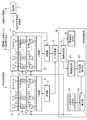
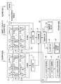
- FIG. 1 is a configuration diagram illustrating a radar device according to a first embodiment.
- FIG. 2 is a hardware configuration diagram illustrating hardware of a signal processing device 20 of the radar device illustrated in FIG. 1.
- FIG. 2 is a hardware configuration diagram of a computer when the signal processing device 20 is realized by software or firmware.
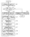
- 9 is a flowchart illustrating a processing procedure when the signal processing device 20 is realized by software or firmware.
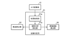
- FIG. 3 is a configuration diagram illustrating a correlation determination unit 21 of the radar device according to the first embodiment.
- FIG. 3 is a configuration diagram illustrating an altitude calculation unit 22 of the radar device according to the first embodiment.
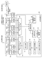
- FIG. 7 is a configuration diagram illustrating a radar device according to a second embodiment.
- FIG. 8 is a hardware configuration diagram illustrating hardware of a signal processing device 20 of the radar device illustrated in FIG. 7.
- FIG. 7 is an explanatory diagram showing a correspondence relationship between a linear distance Rd from the radar device to a plurality of radio wave sources 1 and a beam directing direction ⁇ 0 , and interpolation data indicating a relationship between the linear distance Rd and the beam directing direction ⁇ 0 after interpolation processing.
- FIG. 9 is a configuration diagram illustrating a radar device according to a third embodiment.
- FIG. 11 is a hardware configuration diagram illustrating hardware of a signal processing device 20 of the radar device illustrated in FIG. 10.
- FIG. 1 is a configuration diagram showing a radar device according to the first embodiment.
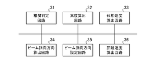
- FIG. 2 is a hardware configuration diagram showing hardware of the signal processing device 20 of the radar device shown in FIG.
- a radio wave source 1 is installed at a position separated by a linear distance Rd from the radar apparatus shown in FIG. 1, and radiates radio waves in a short wave band.
- the frequency of the short wave radio wave is 3 to 30 MHz.
- the frequency f and the linear distance Rd of the radio wave in the short wave band radiated from the radio wave source 1 are known in the radar device shown in FIG.
- the transmitter 2 generates a radar signal as a transmission signal, and outputs the radar signal to the distributor 3 and an analog / digital converter (hereinafter, referred to as an “A / D converter”) 13.
- the distributor 3 divides the radar signal output from the transmitter 2 into N (N is an integer equal to or greater than 1) pieces, and outputs each of the divided radar signals to the phase control unit 4.
- the phase control unit 4 includes N phase shifters 4-1 to 4-N.
- Phase shifter 4-1 ⁇ 4-N adjusts the phase of each radar signals output from the distributor 3 in accordance with the control signal C p which is output from the beam pointing direction setting unit 25, after the phase adjustment of the respective The radar signal is output to variable gain amplifiers 5-1 to 5-N.
- the amplitude control section 5 includes N variable gain amplifiers 5-1 to 5-N.
- Variable gain amplifier 5-1 ⁇ 5-N in accordance with a control signal C a, which is output from the beam pointing direction setting unit 25, adjusts the amplitude of each of the radar signals output from the phase shifter 4-1 ⁇ 4-N Then, the respective radar signals after the amplitude adjustment are output to the transmitting antennas 6-1 to 6-N.
- the transmission array antenna 6 includes N transmission antennas 6-1 to 6-N.
- the transmitting antennas 6-1 to 6-N radiate short-wave radio waves into space as radar waves.
- a dipole antenna, a monopole antenna, or the like can be used as the transmission antennas 6-1 to 6-N.
- the receiving array antenna 7 includes M (M is an integer of 1 or more) receiving antennas 7-1 to 7-M.
- the receiving antennas 7-1 to 7-M receive the radio waves in the short-wave band reflected on the ionosphere, and output the received signals of the radio waves to the variable gain amplifiers 8-1 to 8-M.
- As the receiving antennas 7-1 to 7-M a dipole antenna or a monopole antenna can be used.
- the amplitude control unit 8 includes M variable gain amplifiers 8-1 to 8-M.
- Variable gain amplifiers 8-1 ⁇ 8-M in accordance with a control signal C a, which is output from the beam pointing direction setting unit 25, adjusts the amplitude of each received signal output from the receiving antennas 7-1 ⁇ 7-M , And outputs the received signals after the amplitude adjustment to the phase shifters 9-1 to 9-M.
- the phase control section 9 includes M phase shifters 9-1 to 9-M.
- Phase shifter 9-1 ⁇ 9-M adjusts the phase of each received signal output from the variable gain amplifiers 8-1 ⁇ 8-M according to the control signal C p which is output from the beam pointing direction setting unit 25 , And outputs the received signals after the phase adjustment to the combiner 10.
- the combiner 10 combines the M received signals output from the phase shifters 9-1 to 9-M, and outputs a combined signal, which is the combined received signal, to the receiver 12.
- the receiving antenna 11 receives a direct wave of a short wave radio wave radiated from the radio wave source 1 and outputs a received signal of the direct wave to the receiver 12.
- a dipole antenna, a monopole antenna, or the like can be used as the receiving antenna 11.
- Receiver 12 demodulates the combined signal output from combiner 10 and outputs the combined signal after demodulation to A / D converter 13. Further, the receiver 12 demodulates the received signal of the direct wave output from the receiving antenna 11 and outputs the demodulated received signal to the A / D converter 13.
- the A / D converter 13 converts the radar signal output from the transmitter 2 from an analog signal to a digital signal, and outputs the digital signal to the correlation determination unit 21 as transmission data Tx.
- a / D converter 13 a synthesized signal output from the receiver 12 from an analog signal to a digital signal, and outputs the correlation determination unit 21 the digital signal as the composite data Rx S. Further, A / D converter 13, a received signal output from the receiver 12 from an analog signal to a digital signal, and outputs the correlation determination unit 21 the digital signal as received data Rx D.
- the signal processing device 20 includes a correlation determination unit 21, an altitude calculation unit 22, a phase speed calculation unit 23, a beam directivity calculation unit 24, a beam directivity direction setting unit 25, and a distance speed calculation unit 26.
- the correlation determination unit 21 is realized by, for example, the correlation determination circuit 31 illustrated in FIG.
- Correlation determination unit 21 determines a transmission data Tx outputted from the A / D converter 13, the correlation between the composite data Rx S output from the A / D converter 13.
- Correlation determination unit 21, if there is no correlation between the transmission data Tx and synthetic data Rx S outputs a respective combined data Rx S and the received data Rx D altitude calculation unit 22.
- the altitude calculation unit 22 is realized by, for example, the altitude calculation circuit 32 illustrated in FIG.
- the altitude calculation unit 22 calculates the time difference ⁇ t between the reception time of the direct wave radio wave not reflected by the ionosphere and the reception time of the radio wave reflected by the ionosphere in the short wave band radio waves radiated from the radio wave source 1. calculate. That is, the height calculation unit 22, while delaying the received data Rx D output from the correlation determination unit 21 in the time direction, the delay time correlation is observed between the received data Rx D synthetic data Rx S t d , The time difference ⁇ t between both reception times is calculated.
- the altitude calculator 22 calculates the altitude h of the ionosphere using the time difference ⁇ t and the position of the radio wave source 1, and outputs the altitude h of the ionosphere to the phase velocity calculator 23.
- the phase speed calculation unit 23 is realized by, for example, a phase speed calculation circuit 33 illustrated in FIG.
- the phase velocity calculation unit 23 estimates the electron density ed h of the ionosphere at the altitude h output from the altitude calculation unit 22 with reference to an IRI (International Reference Ionosphere) model, and calculates a short wave band at the altitude h from the electron density ed h. to calculate the radio wave phase velocity v h.
- IRI International Reference Ionosphere
- the phase velocity calculation unit 23 refers to the IRI model, than height h, in estimating the electron density ed h + 1 of the ionosphere in the upper one altitude (h + 1), advanced from the electron density ed h + 1 (h + 1 ) The phase speed v h + 1 of the short wave radio wave is calculated.
- the altitude (h + 1) one level higher than the altitude h is one level higher in the model resolution of the IRI model.
- Phase velocity calculation unit 23 and the phase velocity v h of a radio wave short-wave band in altitude h, the height (h + 1) of a radio wave short-wave band in the phase velocity v h + 1 Tokyo, radio waves incident angle theta h of HF band for ionospheric presume.
- the phase velocity calculator 23 outputs the phase velocity v h and the incident angle ⁇ h of the radio wave to the beam directivity calculator 24.
- the beam pointing direction calculation unit 24 is realized by, for example, a beam pointing direction calculation circuit 34 illustrated in FIG.
- the beam directing direction calculation unit 24 calculates a beam of the short wave radio wave from the phase speed v h and the incident angle ⁇ h of the radio wave output from the phase speed calculation unit 23 and the phase speed v 0 of the short wave radio wave on the ground.
- the pointing direction ⁇ 0 is calculated.
- the beam pointing direction calculation unit 24 outputs the beam pointing direction ⁇ 0 of the short wave radio wave to the beam pointing direction setting unit 25.
- the beam direction setting unit 25 is realized by, for example, a beam direction setting circuit 35 shown in FIG.
- Beam pointing direction setting unit 25 for setting the direction of the radio wave of the short-wave band radiated from the transmission antenna 6-1 ⁇ 6-N in the beam pointing direction theta 0, shift of the phase shifter 4-1 ⁇ 4-N The phase amount and the gains of the variable gain amplifiers 5-1 to 5-N are controlled.
- the distance speed calculation unit 26 is realized by, for example, a distance speed calculation circuit 36 illustrated in FIG.
- Distance velocity calculation unit 26 the synthesized data Rx S output from the correlation determination unit 21, calculates the respective distances L and the target speed V to the target.
- the hardware is realized by dedicated hardware as shown in FIG. That is, it is assumed that the signal processing device 20 is realized by the correlation determination circuit 31, the altitude calculation circuit 32, the phase velocity calculation circuit 33, the beam directivity direction calculation circuit 34, the beam directivity direction setting circuit 35, and the distance speed calculation circuit 36. are doing.
- each of the correlation determination circuit 31, the altitude calculation circuit 32, the phase speed calculation circuit 33, the beam direction calculation circuit 34, the beam direction setting circuit 35, and the distance speed calculation circuit 36 is, for example, a single circuit, a composite circuit. , A programmed processor, a parallel programmed processor, an ASIC (Application Specific Integrated Circuit), an FPGA (Field-Programmable Gate Array), or a combination thereof.
- the components of the signal processing device 20 are not limited to those realized by dedicated hardware. Even if the signal processing device 20 is realized by software, firmware, or a combination of software and firmware, Good. Software or firmware is stored as a program in the memory of the computer.
- the computer means hardware for executing a program, for example, a CPU (Central Processing Unit), a central processing unit, a processing unit, an arithmetic unit, a microprocessor, a microcomputer, a processor, or a DSP (Digital Signal Processor). I do.
- FIG. 3 is a hardware configuration diagram of a computer when the signal processing device 20 is realized by software or firmware.
- FIG. 4 is a flowchart illustrating a processing procedure when the signal processing device 20 is realized by software or firmware.
- FIG. 2 shows an example in which each of the components of the signal processing device 20 is realized by dedicated hardware
- FIG. 3 shows an example in which the signal processing device 20 is realized by software or firmware.
- some components of the signal processing device 20 may be realized by dedicated hardware, and the remaining components may be realized by software or firmware.
- FIG. 5 is a configuration diagram illustrating the correlation determination unit 21 of the radar device according to the first embodiment.
- the correlation processing section 21a sends data Tx outputted from the A / D converter 13, and acquires the respective combined data Rx S and the received data Rx D.
- Correlation processing section 21a is performed a correlation processing between the transmission data Tx and synthetic data Rx S, and outputs the correlation processing result to the correlation determination unit 21b.
- Correlation processing section 21a outputs the respective transmission data Tx, combined data Rx S and the received data Rx D to the correlation determination unit 21b.
- Correlation determination processing section 21b correlation processing result output from the correlation processing unit 21a is, if indicates that the transmission data Tx and synthetic data Rx S are correlated, combined data Rx S distance speed calculating section 26 Output to Correlation determination processing section 21b, the correlation processing result output from the correlation processing unit 21a is, if indicates that the transmission data Tx and synthetic data Rx S is not correlated, the combined data Rx S and the received data Rx D Each is output to the altitude calculation unit 22.
- FIG. 6 is a configuration diagram illustrating the altitude calculation unit 22 of the radar device according to the first embodiment. 6, the correlation processing section 22a, while delaying the received data Rx D output from the correlation determination unit 21 in the time direction, carried out correlation processing with the received data Rx D synthetic data Rx S, correlation The result is output to the time difference calculator 22b.
- Time difference calculating unit 22b, correlation processing result output from the correlation processing unit 22a is, the received data Rx D synthetic data Rx S to search the delay time t d of the received data Rx D indicating that are correlated.
- Time difference calculating unit 22b a direct wave signal reception time of which is not reflected in the ionosphere, as a time difference ⁇ t between the signal reception time, which is reflected in the ionosphere, and outputs the delay time t d to the distance calculation unit 22c .
- the reflection altitude calculation unit 22d holds, as the position of the radio wave source 1, the linear distance Rd between the radar device and the radio wave source 1 shown in FIG.
- the reflection altitude calculation unit 22d calculates the altitude h of the ionosphere using the linear distance Rd and the distance dr output from the distance calculation unit 22c, and outputs the altitude h of the ionosphere to the phase velocity calculation unit 23.
- the operation of the radar device shown in FIG. 1 There are a plurality of radio sources 1 whose linear distance Rd from the radar device shown in FIG. 1 is known, and the frequency f of the short-wave radio waves radiated from each of the plurality of radio sources 1 is known in the radar device. Shall be.
- the radar device shown in FIG. 1 for example, when detecting a target whose linear distance from the radar device is around 100 km, using a radio wave radiated from the radio source 1 having a linear distance Rd from the radar device of about 100 km, Set the beam direction.
- radio waves radiated from the radio wave source 1 having a linear distance Rd from the radar device of about 200 km are used. To set the beam direction.
- the receiving antenna 11 has a substantially horizontal beam direction (a direction at an elevation angle of about 0 degrees) so that a direct wave of a short-wave band radio wave radiated from the radio wave source 1 (a radio wave not reflected by the ionosphere) can be received.
- the receiving antennas 7-1 to 7-M have a substantially vertical beam direction (a direction having an elevation angle of about 90 degrees) so as to be able to receive shortwave radio waves reflected from the ionosphere after being radiated from the radio wave source 1. )
- the radar device shown in FIG. 1 detects a target whose linear distance from the radar device is around 100 km.
- the receiving antenna 11 receives the direct wave of the radio wave radiated from the plurality of radio sources 1
- the receiver 12 selects the radio wave radiated from the radio source 1 having a linear distance Rd of about 100 km from the plurality of direct waves. Extract the waves directly. Since the frequency f of the radio wave radiated from each of the plurality of radio sources 1 is registered in the receiver 12, the receiver 12 selects the radio source 1 having a linear distance Rd of about 100 km from the plurality of direct waves. Can extract the direct wave of the radio wave radiated from.
- the receiver 12 When the receiver 12 extracts a direct wave of a radio wave radiated from the radio source 1 having a linear distance Rd of about 100 km, the receiver 12 demodulates the received signal of the extracted direct wave, and converts the demodulated received signal into an A / D converter 13. Output to A / D converter 13 receives the received signal from the receiver 12, the received signal is converted from an analog signal to a digital signal, and outputs the correlation determination unit 21 the digital signal as received data Rx D.
- the receiving antennas 7-1 to 7-M receive the short-wave radio waves emitted from the radio wave source 1 and reflected by the ionosphere.
- the variable gain amplifiers 8-1 to 8-M adjust the amplitude of the reception signals of the respective radio waves, and Are output to the phase shifters 9-1 to 9-M.
- the phase shifters 9-1 to 9-M adjust the phases of the respective received signals and convert the respective received signals after the phase adjustment. Output to the synthesizer 10.
- the combiner 10 Upon receiving the received signals from the phase shifters 9-1 to 9-M, the combiner 10 receives the received signals of the radio waves radiated from the radio source 1 having a linear distance Rd of about 100 km from the received signals. Is extracted. Since the frequency f of the radio wave radiated from each of the plurality of radio sources 1 is registered in the synthesizer 10, the synthesizer 10 radiates from the radio source 1 having a linear distance Rd of about 100 km from the received signal. It is possible to extract the received signal of the transmitted radio wave. The combiner 10 combines the extracted M received signals and outputs a combined signal, which is the combined received signal, to the receiver 12.
- receiver 12 When receiving the combined signal from combiner 10, receiver 12 demodulates the combined signal and outputs the combined signal after demodulation to A / D converter 13.
- a / D converter 13 receives the composite signal from the receiver 12, the combined signal is converted from an analog signal to a digital signal, and outputs the correlation determination unit 21 the digital signal as the synthesized data Rx S
- the transmitter 2 generates a radar signal and outputs the radar signal to each of the distributor 3 and the A / D converter 13.
- the A / D converter 13 converts the radar signal from an analog signal to a digital signal, and outputs the digital signal to the correlation determination unit 21 as transmission data Tx.
- the transmitter 2 outputs a radar signal to each of the distributor 3 and the A / D converter 13.
- the beam directivity direction setting unit 25 since no setting the beam pointing direction theta 0, beam pointing direction setting unit 25, until the setting of the beam pointing direction theta 0, the transmitter 2 ,
- the radar signal may not be output.
- Correlation processing section 21a of the correlation determination unit 21, carried receives the transmission data Tx from the A / D converter 13, a transmission data Tx, the correlation between the composite data Rx S output from the A / D converter 13 Then, the correlation processing result is output to the correlation determination processing section 21b (step ST1 in FIG. 4). Correlation itself between the transmission data Tx and synthetic data Rx S is a detailed description thereof will be omitted since it is well known in the art. Moreover, the correlation processing section 21a outputs the respective transmission data Tx, combined data Rx S and the received data Rx D to the correlation determination unit 21b.
- the correlation processing unit 21a If the correlation processing unit 21a has not received the transmission data Tx from the A / D converter 13, the correlation processing unit 21a notifies the correlation determination processing unit 21b that the correlation processing has not been performed. Moreover, the correlation processing section 21a outputs the respective combined data Rx S and the received data Rx D to the correlation determination unit 21b.
- Correlation determination processing section 21b correlation processing result output from the correlation processing unit 21a is, if indicates that the transmission data Tx and synthetic data Rx S are correlated (step of FIG. 4 ST2: in the case of YES) , and outputs the synthesized data Rx S the distance speed calculation unit 26.
- Correlation determination processing section 21b correlation processing result output from the correlation processing unit 21a is, if indicates that the transmission data Tx and synthetic data Rx S is not correlated (step of FIG. 4 ST2: in the case of NO) , and outputs a respective combined data Rx S and the received data Rx D altitude calculation unit 22.
- the correlation determination processing unit 21b if receiving the notification that no implementing correlation processing from the correlation processing unit 21a, and outputs the respective combined data Rx S and the received data Rx D altitude calculation unit 22.
- Correlation processing section 22a of the height calculation unit 22 receives the respective combined data Rx S and the received data Rx D from the correlation determination unit 21b, while delaying the received data Rx D in the time direction, and the received data Rx D implementing the correlation between the synthesized data Rx S (step ST3 in FIG. 4). Correlation itself between the received data Rx D synthetic data Rx S is a detailed description thereof will be omitted since it is well known in the art. Correlation processing section 22a outputs the result of a correlation process in each of the delay time t d to the time difference calculating section 22b.
- Time difference calculating section 22b receives the result of a correlation process in each of the delay time from the correlation processing unit 22a t d, with reference to the result of a correlation process in each of the delay time t d, the received data Rx D synthetic data rx S to search the delay time t d are correlated (step ST4 in FIG. 4).
- Time difference calculating unit 22b a direct wave signal reception time of which is not reflected in the ionosphere, as a time difference ⁇ t between the signal reception time, which is reflected in the ionosphere, and outputs the delay time t d to the distance calculation unit 22c .
- Distance calculating unit 22c receives the delay time t d from the time difference calculating portion 22b, as shown in the following equation (1), from the delay time t d, the receiving distance and linear distance Rd of the receiving array antennas 7 Is calculated (step ST5 in FIG. 4).
- c is the propagation speed of the radio wave.
- the distance calculation unit 22c outputs the distance dr to the reflection height calculation unit 22d.
- the reflection altitude calculation unit 22d uses the linear distance Rd between the radar device and the radio wave source 1 and the distance dr output from the distance calculation unit 22c to calculate the ionosphere as shown in the following equation (2).
- the altitude h is calculated, and the altitude h of the ionosphere is output to the phase velocity calculator 23 (step ST6 in FIG. 4).
- the phase velocity calculating unit 23 Upon receiving the ionospheric altitude h from the reflection altitude calculating unit 22d, the phase velocity calculating unit 23 estimates the electron density ed h of the ionosphere at the altitude h with reference to, for example, an IRI model.
- the IRI model is a database showing the correspondence between altitude h and electron density ed h .
- the IRI model may be held by the phase velocity calculator 23 or may be held by a device external to the radar device.
- the phase velocity calculating unit 23 calculates the phase velocity v h of the short wave radio wave at the altitude h from the electron density ed h as shown in the following equation (3) (see FIG. 4). Step ST7).
- ⁇ is a plasma frequency determined by the electron density ed h of the ionosphere
- k is a wave number.
- Phase velocity calculation unit 23 for example, with reference to the IRI model, than height h, in estimating the electron density ed h + 1 of the ionosphere in the upper one altitude (h + 1), advanced from the electron density ed h + 1 (h + 1 ) The phase speed v h + 1 of the short wave radio wave is calculated.
- the altitude (h + 1) one level higher than the altitude h is one level higher in the model resolution of the IRI model.
- the phase velocity calculator 23 outputs the phase velocity v h and the incident angle ⁇ h of the radio wave to the beam directivity calculator 24.
- the beam pointing direction calculation unit 24 calculates the phase velocity v h and the incident angle ⁇ h output from the phase velocity calculation unit 23 and the phase velocity v 0 of the short wave radio wave on the ground. Then, the beam directing direction ⁇ 0 of the short wave radio wave is calculated (step ST8 in FIG. 4).
- the phase velocity v 0 radio waves of short wave band in the ground are known.
- the ground corresponds to the altitude at which the receiving antennas 7-1 to 7-M are installed.
- ⁇ w is the beam width of the short-wave radio wave radiated from the transmitting antennas 6-1 to 6-N.
- the beam pointing direction calculation unit 24 outputs the beam pointing direction ⁇ 0 of the short wave radio wave to the beam pointing direction setting unit 25.
- the phase amount and the gains of the variable gain amplifiers 5-1 to 5-N are controlled (step ST9 in FIG. 4).
- the beam pointing direction setting unit 25 for setting the direction of the radio wave of the short-wave band, which is received by the receiving antennas 7-1 ⁇ 7-N in the beam pointing direction theta 0, the variable gain amplifiers 8-1 ⁇ 8-N And the phase shift amounts of the phase shifters 9-1 to 9-N are controlled (step ST9 in FIG. 4).
- the beam directivity direction setting unit 25 calculates the amplitude and phase of the radar signal for setting the direction of the radio beam pointing direction theta 0. Then, the beam directivity direction setting unit 25 outputs a control signal C a indicating the amplitude in each of the variable gain amplifier 5-1 ⁇ 5-N and the variable gain amplifier 8-1 ⁇ 8-N. The beam pointing direction setting unit 25 outputs a control signal C p indicating the phase on each of the phase shifter 4-1 ⁇ 4-N and the phase shifter 9-1 ⁇ 9-N.
- the process of calculating the amplitude and phase corresponding to the beam directing direction ⁇ 0 itself is a known technique, and a detailed description thereof will be omitted.
- distributor 3 Upon receiving the radar signal from transmitter 2, distributor 3 divides the radar signal into N signals, and outputs the divided radar signals to phase shifters 4-1 to 4-N.
- Phase shifter 4-1 ⁇ 4-N adjusts the phase of each radar signals output from the distributor 3 in accordance with the control signal C p which is output from the beam pointing direction setting unit 25, after the phase adjustment of the respective The radar signal is output to variable gain amplifiers 5-1 to 5-N.
- Variable gain amplifier 5-1 ⁇ 5-N in accordance with a control signal C a, which is output from the beam pointing direction setting unit 25, adjusts the amplitude of each of the radar signals output from the phase shifter 4-1 ⁇ 4-N Then, the respective radar signals after the amplitude adjustment are output to the transmitting antennas 6-1 to 6-N.
- the transmitting antennas 6-1 to 6-N When receiving the respective radar signals from the variable gain amplifiers 5-1 to 5-N, the transmitting antennas 6-1 to 6-N radiate short-wave radio waves into space as radar waves.
- the beam pointing direction ⁇ 0 of the radio waves radiated from the transmitting antennas 6-1 to 6-N is set by using the radio waves radiated from the radio source 1 having a linear distance Rd from the radar device of about 100 km. It is possible to irradiate a target with a linear distance of around 100 km with a radio wave.
- the receiving antennas 7-1 to 7-M receive the short-wave radio waves radiated from the transmitting antennas 6-1 to 6-N and then reflected back to the target, and convert the received radio wave signals into variable gain amplifiers. 8-1 to 8-M.
- the beam pointing direction ⁇ 0 of radio waves received by the receiving antennas 7-1 to 7-M is set using radio waves radiated from the radio source 1 having a linear distance Rd from the radar device of about 100 km. It is possible to receive a radio wave reflected by a target whose linear distance is around 100 km.
- the beam pointing direction ⁇ 0 calculated by the beam pointing direction calculation unit 24 is an elevation angle direction, not an azimuth angle direction.
- the azimuth direction of the radio wave radiated from the transmitting antennas 6-1 to 6-N may be a direction set in advance, or may rotate in the range of 0 to 360 degrees.
- the azimuth direction of the radio waves received by the receiving antennas 7-1 to 7-M may be a direction set in advance, or may rotate in the range of 0 to 360 degrees. Good.
- Variable gain amplifiers 8-1 ⁇ 8-M in accordance with a control signal C a, which is output from the beam pointing direction setting unit 25, adjusts the amplitude of each received signal output from the receiving antennas 7-1 ⁇ 7-M , And outputs the received signals after the amplitude adjustment to the phase shifters 9-1 to 9-M.
- Phase shifter 9-1 ⁇ 9-M adjusts the phase of each received signal output from the variable gain amplifiers 8-1 ⁇ 8-M according to the control signal C p which is output from the beam pointing direction setting unit 25 , And outputs the received signals after the phase adjustment to the combiner 10.
- the combiner 10 Upon receiving the respective received signals from the phase shifters 9-1 to 9-M, the combiner 10 combines the M received signals and outputs a combined signal, which is the combined received signal, to the receiver 12.
- receiver 12 demodulates the combined signal and outputs the combined signal after demodulation to A / D converter 13.
- a / D converter 13 receives the composite signal from the receiver 12, the combined signal is converted from an analog signal to a digital signal, and outputs the correlation determination unit 21 the digital signal as the synthesized data Rx S
- Correlation determination processing section 21b correlation processing result output from the correlation processing unit 21a is, if indicates that the transmission data Tx and synthetic data Rx S are correlated (step of FIG. 4 ST2: in the case of YES) , and outputs the synthesized data Rx S the distance speed calculation unit 26.
- the receiving antennas 7-1 to 7-M are receiving shortwave radio waves that have been radiated from the transmitting antennas 6-1 to 6-N and then reflected back to the target, the transmission data Tx synthetic data Rx S are correlated.
- Distance velocity calculation unit 26 calculates the receiving the synthetic data Rx S from the correlation determination unit 21, the combined data Rx S, the respective distances L and the target speed V to the target (step ST10 in FIG. 4). Process itself of calculating the combined data Rx S, the distance L and the target velocity V to the target, the detailed description thereof is omitted because it is known in the art.
- the beam direction of the short wave radio wave is determined from the phase speed calculated by the phase speed calculation unit 23, the incident angle estimated by the phase speed calculation unit 23, and the phase speed of the short wave radio wave on the ground.
- a beam pointing direction calculating unit 24 for calculating the direction is provided, and the beam pointing direction setting unit 25 controls the directions of the radio waves in the short wave band radiated from the transmitting antennas 6-1 to 6-N and the receiving antennas 7-1 to 7-M.
- the radar device is configured to set each of the directions of the radio waves in the short wave band received by the beam pointing direction calculated by the beam pointing direction calculation unit 24. Therefore, the radar device according to the first embodiment can detect a target existing in a desired area.
- Embodiment 2 FIG. In the second embodiment, a radar device that sets the beam pointing direction ⁇ 0 of radio waves using radio waves radiated from a plurality of radio sources 1 will be described.
- FIG. 7 is a configuration diagram illustrating a radar device according to the second embodiment.
- FIG. 8 is a hardware configuration diagram showing hardware of the signal processing device 20 of the radar device shown in FIG. 7 and 8, the same reference numerals as those in FIGS. 1 and 2 denote the same or corresponding parts, and a description thereof will not be repeated.
- the beam directivity interpolating unit 27 is realized by, for example, a beam directivity interpolator 37 shown in FIG.
- the beam pointing direction interpolation unit 27 interpolates between the plurality of beam pointing directions calculated by the beam pointing direction calculation unit 24.
- the correlation determination unit 21, the altitude calculation unit 22, the phase velocity calculation unit 23, and the beam directivity calculation unit 24 use radio waves radiated from one radio source 1 as in the first embodiment. Is used to calculate the beam pointing direction ⁇ 0 of the radio wave. Further, in the radar apparatus shown in FIG. 7, the correlation determination unit 21, the altitude calculation unit 22, the phase velocity calculation unit 23, and the beam directivity calculation unit 24 are radiated from one radio source 1 different from the above radio source 1. The beam direction ⁇ 0 of the radio wave is calculated using the radio wave. In the radar device shown in FIG. 7, the correlation determination unit 21, the altitude calculation unit 22, the phase velocity calculation unit 23, and the beam directivity calculation unit 24 use radio waves radiated from the plurality of radio sources 1 to The beam directing direction ⁇ 0 is calculated.
- Beam pointing direction calculation unit 24 uses the radio wave radiated from the radio wave source 1, every time to calculate the beam pointing direction theta 0 of the radio wave, straight line distance Rd and beam pointing direction theta 0 of the said radio sources 1
- the set is output to the beam direction interpolator 27.
- FIG. 9 shows interpolation data indicating the correspondence between the linear distance Rd from the radar device to the plurality of radio wave sources 1 and the beam pointing direction ⁇ 0 , and the relationship between the linear distance Rd and the beam pointing direction ⁇ 0 after the interpolation processing.
- the beam pointing direction interpolation unit 27 acquires a plurality of pairs of the linear distance Rd to the radio wave source 1 and the beam pointing direction ⁇ 0 from the beam pointing direction calculation unit 24, the beam pointing directions ⁇ discretely obtained are obtained.
- An interpolation process for interpolating between 0 is performed.
- processing such as least squares method or spline interpolation can be used.
- the beam pointing direction interpolation unit 27 outputs interpolation data indicating the relationship between the linear distance Rd after the interpolation processing and the beam pointing direction ⁇ 0 to the beam pointing direction setting unit 25.
- the beam directivity setting unit 25 refers to the interpolation data output from the beam directivity interpolating unit 27 to determine the beam directivity corresponding to the linear distance X. Specify ⁇ 0 .
- the beam pointing direction setting unit 25 for setting the direction of the radio wave of the short-wave band, which is received by the receiving antennas 7-1 ⁇ 7-N in the beam pointing direction theta 0, the variable gain amplifiers 8-1 ⁇ 8-N And the phase shift amounts of the phase shifters 9-1 to 9-N are controlled.
- the radar apparatus is configured to include the beam directivity interpolating unit 27 that interpolates between the plurality of beam directivities calculated by the beam directivity calculating unit 24. Therefore, the radar device according to the second embodiment can detect the target by radiating radio waves to the target existing at an intermediate distance between the two linear distances Rd.
- Embodiment 3 The radar apparatuses according to the first and second embodiments include amplitude controllers 5 and 8 and phase controllers 4 and 9 to change the beam directing direction.
- a radar device including a transmission digital beamforming unit 53 and a reception digital beamforming unit 54 for changing the beam directing direction will be described.
- FIG. 10 is a configuration diagram showing a radar device according to the third embodiment.
- FIG. 11 is a hardware configuration diagram showing hardware of the signal processing device 20 of the radar device shown in FIG. 10 and 11, the same reference numerals as those in FIGS. 1, 2, 7, and 8 denote the same or corresponding parts, and a description thereof will not be repeated.
- the signal generation unit 51 is realized by, for example, a signal generation circuit 61 illustrated in FIG.
- the signal generation unit 51 generates transmission data corresponding to the transmission data Tx output from the A / D converter 13 shown in FIG. 1, and outputs the transmission data to the transmission digital beamforming unit 53 and the correlation determination unit 21.
- the beam direction setting unit 52 is realized by, for example, a beam direction setting circuit 62 shown in FIG. Beam pointing direction setting unit 52, the transmitting antenna 6-1 to set the direction of the radio wave of the short-wave band, which is radiated in the beam pointing direction theta 0 from ⁇ 6-N, the radio wave direction of the adjustment in the transmit digital beam forming unit 53 Control.
- the beam pointing direction setting unit 52 sets the direction of the radio wave in the short-wave band received by the receiving antennas 7-1 to 7-N to the beam pointing direction ⁇ 0 , so that the direction of the radio wave in the reception digital beam forming unit 54 is set. To control the adjustment.
- the transmission digital beamforming unit 53 is realized by, for example, a transmission digital beamforming circuit 63 shown in FIG.
- the transmission digital beamforming unit 53 distributes the transmission data output from the signal generation unit 51 into N pieces.
- the transmission data after distribution is controlled.
- the transmission digital beamforming unit 53 outputs the controlled transmission data to digital-to-analog converters (hereinafter, referred to as “D / A converters”) 55-1 to 55-N.
- D / A converters digital-to-analog converters
- the reception digital beamforming unit 54 is realized by, for example, a reception digital beamforming circuit 64 shown in FIG.
- the respective received data output from the A / D converters 56-1 to 56-M are controlled.
- Receiving digital beam forming unit 54 combines the respective received data after control, the combined data of the received data, as data corresponding to the combined data Rx S output from the A / D converter 13 shown in FIG. 1, Output to the correlation determination unit 21.
- the digital-to-analog converter 55 includes N D / A converters 55-1 to 55-N.
- the D / A converters 55-1 to 55-N convert each transmission data output from the transmission digital beamforming unit 53 from a digital signal to an analog signal, and convert each analog signal as a radar signal to the transmission antenna 6.
- the analog-to-digital converter 56 includes M A / D converters 56-1 to 56-M.
- the A / D converters 56-1 to 56-M convert the respective reception signals received by the reception antennas 7-1 to 7-N from analog signals to digital signals, and convert the respective digital signals into reception data. Output to the reception digital beamforming unit 54.
- the A / D converter 57 converts the direct wave reception signal output from the reception antenna 11 from an analog signal to a digital signal, and converts the digital signal into reception data output from the A / D converter 13 shown in FIG. as data corresponding to rx D, and outputs the correlation determination unit 21.
- the operation of the radar device shown in FIG. 10 will be described.
- the signal generation unit 51 the beam directivity setting unit 52, the transmission digital beamforming unit 53, the reception digital beamforming unit 54, the digital / analog conversion unit 55, the analog / digital conversion unit 56, and the A / D converter 57
- the implementation is the same. This is similar to the first and second embodiments. Here, only portions different from the first and second embodiments will be described.
- the signal generation unit 51 generates transmission data corresponding to the transmission data Tx output from the A / D converter 13 shown in FIG. 1, and outputs the transmission data to the transmission digital beamforming unit 53 and the correlation determination unit 21.
- the beam pointing direction setting unit 52 Upon receiving the beam pointing direction ⁇ 0 of the radio wave from the beam direction interpolating unit 27, the beam pointing direction setting unit 52 changes the direction of the short wave band radio wave radiated from the transmitting antennas 6-1 to 6-N to the beam pointing direction ⁇ . In order to set it to 0 , the adjustment of the direction of the radio wave in the transmission digital beam forming unit 53 is controlled.
- the beam pointing direction setting unit 52 sets the direction of the radio wave in the short-wave band received by the receiving antennas 7-1 to 7-N to the beam pointing direction ⁇ 0 , so that the direction of the radio wave in the reception digital beam forming unit 54 is set. To control the adjustment.
- the transmission digital beamforming unit 53 Upon receiving the transmission data from the signal generation unit 51, the transmission digital beamforming unit 53 distributes the transmission data into N pieces. Transmission digital beam forming unit 53, the transmitting antenna 6-1 to adjust the direction of the radio wave of the short-wave band, which is radiated in the beam pointing direction theta 0 from ⁇ 6-N, control signals outputted from the beam pointing direction setting unit 52 , The transmission data after distribution is controlled. To adjust the direction of the radio wave of the short-wave band radiated from the transmission antenna 6-1 ⁇ 6-N in the beam pointing direction theta 0, the process itself to control the respective transmission data after the distribution are known in the art Therefore, detailed description is omitted.
- the transmission digital beamforming unit 53 outputs the respective controlled transmission data to the D / A converters 55-1 to 55-N.
- the D / A converters 55-1 to 55-N convert each transmission data output from the transmission digital beamforming unit 53 from a digital signal to an analog signal, and convert each analog signal as a radar signal to the transmission antenna 6. Output to -1 to 6-N.
- the A / D converters 56-1 to 56-M convert the respective reception signals received by the reception antennas 7-1 to 7-N from analog signals to digital signals, and convert the respective digital signals into reception data. Output to the reception digital beamforming unit 54.
- the A / D converter 57 converts the direct wave reception signal output from the reception antenna 11 from an analog signal to a digital signal, and converts the digital signal into reception data output from the A / D converter 13 shown in FIG. as data corresponding to rx D, and outputs the correlation determination unit 21.
- the reception digital beamforming unit 54 adjusts the direction of the radio wave received by the reception antennas 7-1 to 7-N to the beam pointing direction ⁇ 0 according to the control signal output from the beam pointing direction setting unit 52.
- the respective received data output from the / D converters 56-1 to 56-M are controlled.
- Receiving digital beam forming unit 54 combines the respective received data after control, the combined data of the received data, as data corresponding to the combined data Rx S output from the A / D converter 13 shown in FIG. 1, Output to the correlation determination unit 21.
- the radar apparatus includes the transmission digital beamforming unit 53 and the reception digital beamforming unit 54 in order to change the beam directing direction.
- the radar device including the transmission digital beamforming unit 53 and the reception digital beamforming unit 54 can detect a target existing in a desired area, similarly to the radar devices illustrated in FIGS. 1 and 7.
- Embodiment 4 FIG.
- a dipole antenna or a monopole antenna is used as transmission antennas 6-1 to 6-N and reception antennas 7-1 to 7-N.
- each of transmitting antennas 6-1 to 6-N and receiving antennas 7-1 to 7-N is a radar whose beam directing direction is variable by adjusting the antenna element length. The device will be described.
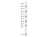
- antenna elements 71-1 to 71-6 are elements included in transmission antenna 6-n.
- the antenna element 71-1 is an element on the base end side, and is connected to the variable gain amplifier 5-n.
- the antenna element 71-6 is a tip-side element.
- the transmission antenna 6-n includes six antenna elements 71-1 to 71-6. However, this is only an example, and the transmitting antenna 6-n may include two or more and five or less antenna elements, or may include seven or more antenna elements. May be.
- the switch 72-1 is an element for switching a connection state between the antenna element 71-1 and the antenna element 71-2.
- the switch 72-2 changes the connection state between the antenna element 71-2 and the antenna element 71-3 when the switch 72-1 connects the antenna element 71-1 and the antenna element 71-2. It is a switching element.
- the switch 72-3 changes the connection state between the antenna element 71-3 and the antenna element 71-4 when the switch 72-2 connects the antenna element 71-2 and the antenna element 71-3. It is a switching element.
- the switch 72-4 changes the connection state between the antenna element 71-4 and the antenna element 71-5 when the switch 72-3 connects the antenna element 71-3 and the antenna element 71-4. It is a switching element.
- the switch 72-5 changes the connection state between the antenna element 71-5 and the antenna element 71-6 when the switch 72-4 connects the antenna element 71-4 and the antenna element 71-5. It is a switching element. The switching of the connection state by the switches 72-1 to 72-5 is controlled by the beam directivity setting unit 25.
- antenna elements 81-1 to 81-6 are elements included in receiving antenna 7-m.
- the antenna element 81-1 is an element on the base end side, and is connected to the variable gain amplifier 8-m.
- the antenna element 81-6 is a tip-side element.
- the receiving antenna 7-m includes six antenna elements 81-1 to 81-6. However, this is only an example, and the receiving antenna 7-m may include two or more and five or less antenna elements, or may include seven or more antenna elements. May be.
- the switch 82-1 is an element for switching a connection state between the antenna element 81-1 and the antenna element 81-2.
- the switch 82-2 changes the connection state between the antenna element 81-2 and the antenna element 81-3 when the switch 82-1 connects the antenna element 81-1 and the antenna element 81-2. It is a switching element.
- the switch 82-3 changes the connection state between the antenna element 81-3 and the antenna element 81-4 when the switch 82-2 connects the antenna element 81-2 and the antenna element 81-3. It is a switching element.
- the switch 82-4 changes the connection state between the antenna element 81-4 and the antenna element 81-5 when the switch 82-3 connects the antenna element 81-3 and the antenna element 81-4. It is a switching element.
- the switch 82-5 changes the connection state between the antenna element 81-5 and the antenna element 81-6 when the switch 82-4 connects the antenna element 81-4 and the antenna element 81-5. It is a switching element. The switching of the connection state by the switches 82-1 to 82-5 is controlled by the beam directivity setting unit 25.
- the antenna element length of the transmitting antenna 6-n is controlled by the beam directivity setting unit 25 to turn on only the switch 72-1 (connected state) and turn off the switches 72-2 to 72-5 (disconnected state).
- the antenna element length of the transmitting antenna 6-n is the longest when the beam directivity setting unit 25 controls all the switches 72-1 to 72-5 to be ON.
- the beam pointing direction setting unit 25 controls ON / OFF of the switches 72-1 to 72-5, so that the antenna element length of the transmitting antenna 6-n changes.
- the elevation angles indicating the beam directing directions of the transmission antennas 6-1 to 6-N when the antenna element lengths of the transmission antennas 6-1 to 6-N are short are such that the antenna element length of the transmission antennas 6-1 to 6-N is long. It becomes smaller than the elevation angle indicating the beam directing direction of the transmitting antennas 6-1 to 6-N. Therefore, the beam directing direction setting unit 25 controls the ON / OFF of the switches 72-1 to 72-5, so that the beam directing directions of the transmitting antennas 6-1 to 6-N can be changed.
- the antenna element length of the receiving antenna 7-m is the shortest when the beam directivity setting unit 25 controls only the switch 82-1 to be ON and switches 82-2 to 82-5 to be OFF.
- the antenna element length of the receiving antenna 7-m becomes the longest when the beam directivity setting unit 25 controls all the switches 82-1 to 82-5 to be ON.
- the antenna element length of the receiving antenna 7-m changes.
- the elevation angles indicating the beam directing directions of the receiving antennas 7-1 to 7-M when the antenna element lengths of the receiving antennas 7-1 to 7-M are short are such that the antenna element lengths of the receiving antennas 7-1 to 7-M are long.
- the beam pointing direction setting unit 25 can change the beam pointing directions of the receiving antennas 7-1 to 7-M by controlling ON / OFF of the switches 82-1 to 82-5.
- any combination of the embodiments, a modification of an arbitrary component of each embodiment, or an omission of any component in each embodiment is possible within the scope of the invention. .
- the present invention is suitable for a radar apparatus for setting the beam directing direction of a short-wave radio wave.
Landscapes
- Engineering & Computer Science (AREA)
- Computer Networks & Wireless Communication (AREA)
- Physics & Mathematics (AREA)
- General Physics & Mathematics (AREA)
- Radar, Positioning & Navigation (AREA)
- Remote Sensing (AREA)
- Radar Systems Or Details Thereof (AREA)
Abstract
位相速度算出部(23)により算出された位相速度、位相速度算出部(23)により推定された入射角度及び地上における短波帯の電波の位相速度から、短波帯の電波のビーム指向方向を算出するビーム指向方向算出部(24)を設け、ビーム指向方向設定部(25)が、送信アンテナ(6-1)~(6-N)から放射される短波帯の電波の方向及び受信アンテナ(7-1)~(7-M)により受信される短波帯の電波の方向のそれぞれをビーム指向方向算出部(24)により算出されたビーム指向方向に設定するように、レーダ装置を構成した。
Description
この発明は、短波帯の電波のビーム指向方向を設定するレーダ装置に関するものである。
地上から放射された短波(HF:High Frequency)帯の電波は、電離層内で屈折されて、見通し外の遠方まで伝搬されることが知られている。
目標を検出するレーダ装置が、電離層に反射された短波帯の電波を利用すれば、見通し外の遠方に存在している目標を検出することが可能である。
目標を検出するレーダ装置が、電離層に反射された短波帯の電波を利用すれば、見通し外の遠方に存在している目標を検出することが可能である。
以下の特許文献1には、電離層における電子密度と高さの関係を示すデータを参照して、短波帯の電波の屈折角を求めることで、電波の伝搬経路を算出している伝搬経路計算装置が開示されている。
従来のレーダ装置は、特許文献1に開示されている伝搬経路計算装置を用いることが可能であるとすれば、短波帯の電波の伝搬経路を得ることができる。
しかし、特許文献1に開示されている伝搬経路計算装置は、短波帯の電波の伝搬経路から、短波帯の電波の放射方向を算出するものではない。
したがって、従来のレーダ装置は、特許文献1に開示されている伝搬経路計算装置を用いることが可能であるとしても、目標を検出する上で適正な電波の放射方向を算出することができない。つまり、所望の領域に存在している目標に電波を照射して、目標を検出できないことがあるという課題があった。
しかし、特許文献1に開示されている伝搬経路計算装置は、短波帯の電波の伝搬経路から、短波帯の電波の放射方向を算出するものではない。
したがって、従来のレーダ装置は、特許文献1に開示されている伝搬経路計算装置を用いることが可能であるとしても、目標を検出する上で適正な電波の放射方向を算出することができない。つまり、所望の領域に存在している目標に電波を照射して、目標を検出できないことがあるという課題があった。
この発明は上記のような課題を解決するためになされたもので、所望の領域に存在している目標を検出することができるレーダ装置を得ることを目的とする。
この発明に係るレーダ装置は、短波帯の電波を放射する電波源の位置を用いて、短波帯の電波を反射する電離層の高度を算出する高度算出部と、高度算出部により算出された高度における短波帯の電波の位相速度を算出し、位相速度を用いて、電離層に対する短波帯の電波の入射角度を推定する位相速度算出部と、位相速度算出部により算出された位相速度、入射角度及び地上における短波帯の電波の位相速度から、短波帯の電波のビーム指向方向を算出するビーム指向方向算出部と、送信アンテナから放射される短波帯の電波の方向及び受信アンテナにより受信される短波帯の電波の方向のそれぞれをビーム指向方向算出部により算出されたビーム指向方向に設定するビーム指向方向設定部とを備えるようにしたものである。
この発明によれば、位相速度算出部により算出された位相速度、入射角度及び地上における短波帯の電波の位相速度から、短波帯の電波のビーム指向方向を算出するビーム指向方向算出部を設け、ビーム指向方向設定部が、送信アンテナから放射される短波帯の電波の方向及び受信アンテナにより受信される短波帯の電波の方向のそれぞれをビーム指向方向算出部により算出されたビーム指向方向に設定するように、レーダ装置を構成した。したがって、この発明に係るレーダ装置は、所望の領域に存在している目標を検出することができる。
以下、この発明をより詳細に説明するために、この発明を実施するための形態について、添付の図面に従って説明する。
実施の形態1.
図1は、実施の形態1によるレーダ装置を示す構成図である。
図2は、図1に示すレーダ装置の信号処理装置20のハードウェアを示すハードウェア構成図である。
図1において、電波源1は、図1に示すレーダ装置から直線距離でRdだけ離れている位置に設置されており、短波帯の電波を放射する。短波帯の電波の周波数は、3~30MHzである。
電波源1から放射される短波帯の電波の周波数f及び直線距離Rdは、図1に示すレーダ装置において既知である。
図1は、実施の形態1によるレーダ装置を示す構成図である。
図2は、図1に示すレーダ装置の信号処理装置20のハードウェアを示すハードウェア構成図である。
図1において、電波源1は、図1に示すレーダ装置から直線距離でRdだけ離れている位置に設置されており、短波帯の電波を放射する。短波帯の電波の周波数は、3~30MHzである。
電波源1から放射される短波帯の電波の周波数f及び直線距離Rdは、図1に示すレーダ装置において既知である。
送信器2は、送信信号としてレーダ信号を生成し、レーダ信号を分配器3及びアナログデジタル変換器(以下、「A/D変換器」と称する)13に出力する。
分配器3は、送信器2から出力されたレーダ信号をN(Nは1以上の整数)個に分配し、分配後のそれぞれのレーダ信号を位相制御部4に出力する。
分配器3は、送信器2から出力されたレーダ信号をN(Nは1以上の整数)個に分配し、分配後のそれぞれのレーダ信号を位相制御部4に出力する。
位相制御部4は、N個の移相器4-1~4-Nを備えている。
移相器4-1~4-Nは、ビーム指向方向設定部25から出力された制御信号Cpに従って分配器3から出力されたそれぞれのレーダ信号の位相を調整し、位相調整後のそれぞれのレーダ信号を可変利得アンプ5-1~5-Nに出力する。
振幅制御部5は、N個の可変利得アンプ5-1~5-Nを備えている。
可変利得アンプ5-1~5-Nは、ビーム指向方向設定部25から出力された制御信号Caに従って、移相器4-1~4-Nから出力されたそれぞれのレーダ信号の振幅を調整し、振幅調整後のそれぞれのレーダ信号を送信アンテナ6-1~6-Nに出力する。
送信アレイアンテナ6は、N個の送信アンテナ6-1~6-Nを備えている。
送信アンテナ6-1~6-Nは、可変利得アンプ5-1~5-Nからそれぞれのレーダ信号を受けると、レーダ波として、短波帯の電波を空間に放射する。
送信アンテナ6-1~6-Nとしては、ダイポールアンテナ又はモノポールアンテナなどを用いることができる。
移相器4-1~4-Nは、ビーム指向方向設定部25から出力された制御信号Cpに従って分配器3から出力されたそれぞれのレーダ信号の位相を調整し、位相調整後のそれぞれのレーダ信号を可変利得アンプ5-1~5-Nに出力する。
振幅制御部5は、N個の可変利得アンプ5-1~5-Nを備えている。
可変利得アンプ5-1~5-Nは、ビーム指向方向設定部25から出力された制御信号Caに従って、移相器4-1~4-Nから出力されたそれぞれのレーダ信号の振幅を調整し、振幅調整後のそれぞれのレーダ信号を送信アンテナ6-1~6-Nに出力する。
送信アレイアンテナ6は、N個の送信アンテナ6-1~6-Nを備えている。
送信アンテナ6-1~6-Nは、可変利得アンプ5-1~5-Nからそれぞれのレーダ信号を受けると、レーダ波として、短波帯の電波を空間に放射する。
送信アンテナ6-1~6-Nとしては、ダイポールアンテナ又はモノポールアンテナなどを用いることができる。
受信アレイアンテナ7は、M(Mは1以上の整数)個の受信アンテナ7-1~7-Mを備えている。
受信アンテナ7-1~7-Mは、電離層に反射された短波帯の電波を受信し、電波の受信信号を可変利得アンプ8-1~8-Mに出力する。
受信アンテナ7-1~7-Mとしては、ダイポールアンテナ又はモノポールアンテナなどを用いることができる。
振幅制御部8は、M個の可変利得アンプ8-1~8-Mを備えている。
可変利得アンプ8-1~8-Mは、ビーム指向方向設定部25から出力された制御信号Caに従って、受信アンテナ7-1~7-Mから出力されたそれぞれの受信信号の振幅を調整し、振幅調整後のそれぞれの受信信号を移相器9-1~9-Mに出力する。
位相制御部9は、M個の移相器9-1~9-Mを備えている。
移相器9-1~9-Mは、ビーム指向方向設定部25から出力された制御信号Cpに従って可変利得アンプ8-1~8-Mから出力されたそれぞれの受信信号の位相を調整し、位相調整後のそれぞれの受信信号を合成器10に出力する。
合成器10は、移相器9-1~9-Mから出力されたM個の受信信号を合成し、合成した受信信号である合成信号を受信器12に出力する。
受信アンテナ7-1~7-Mは、電離層に反射された短波帯の電波を受信し、電波の受信信号を可変利得アンプ8-1~8-Mに出力する。
受信アンテナ7-1~7-Mとしては、ダイポールアンテナ又はモノポールアンテナなどを用いることができる。
振幅制御部8は、M個の可変利得アンプ8-1~8-Mを備えている。
可変利得アンプ8-1~8-Mは、ビーム指向方向設定部25から出力された制御信号Caに従って、受信アンテナ7-1~7-Mから出力されたそれぞれの受信信号の振幅を調整し、振幅調整後のそれぞれの受信信号を移相器9-1~9-Mに出力する。
位相制御部9は、M個の移相器9-1~9-Mを備えている。
移相器9-1~9-Mは、ビーム指向方向設定部25から出力された制御信号Cpに従って可変利得アンプ8-1~8-Mから出力されたそれぞれの受信信号の位相を調整し、位相調整後のそれぞれの受信信号を合成器10に出力する。
合成器10は、移相器9-1~9-Mから出力されたM個の受信信号を合成し、合成した受信信号である合成信号を受信器12に出力する。
受信アンテナ11は、電波源1から放射された短波帯の電波の直接波を受信し、直接波の受信信号を受信器12に出力する。
受信アンテナ11としては、ダイポールアンテナ又はモノポールアンテナなどを用いることができる。
受信器12は、合成器10から出力された合成信号を復調し、復調後の合成信号をA/D変換器13に出力する。
また、受信器12は、受信アンテナ11から出力された直接波の受信信号を復調し、復調後の受信信号をA/D変換器13に出力する。
A/D変換器13は、送信器2から出力されたレーダ信号をアナログ信号からデジタル信号に変換し、デジタル信号を送信データTxとして相関判定部21に出力する。
また、A/D変換器13は、受信器12から出力された合成信号をアナログ信号からデジタル信号に変換し、デジタル信号を合成データRxSとして相関判定部21に出力する。
さらに、A/D変換器13は、受信器12から出力された受信信号をアナログ信号からデジタル信号に変換し、デジタル信号を受信データRxDとして相関判定部21に出力する。
受信アンテナ11としては、ダイポールアンテナ又はモノポールアンテナなどを用いることができる。
受信器12は、合成器10から出力された合成信号を復調し、復調後の合成信号をA/D変換器13に出力する。
また、受信器12は、受信アンテナ11から出力された直接波の受信信号を復調し、復調後の受信信号をA/D変換器13に出力する。
A/D変換器13は、送信器2から出力されたレーダ信号をアナログ信号からデジタル信号に変換し、デジタル信号を送信データTxとして相関判定部21に出力する。
また、A/D変換器13は、受信器12から出力された合成信号をアナログ信号からデジタル信号に変換し、デジタル信号を合成データRxSとして相関判定部21に出力する。
さらに、A/D変換器13は、受信器12から出力された受信信号をアナログ信号からデジタル信号に変換し、デジタル信号を受信データRxDとして相関判定部21に出力する。
信号処理装置20は、相関判定部21、高度算出部22、位相速度算出部23、ビーム指向方向算出部24、ビーム指向方向設定部25及び距離速度算出部26を備えている。
相関判定部21は、例えば、図2に示す相関判定回路31によって実現される。
相関判定部21は、A/D変換器13から出力された送信データTxと、A/D変換器13から出力された合成データRxSとの相関を判定する。
相関判定部21は、送信データTxと合成データRxSとの間に相関があれば、合成データRxSを距離速度算出部26に出力する。
相関判定部21は、送信データTxと合成データRxSとの間に相関がなければ、合成データRxS及び受信データRxDのそれぞれを高度算出部22に出力する。
相関判定部21は、例えば、図2に示す相関判定回路31によって実現される。
相関判定部21は、A/D変換器13から出力された送信データTxと、A/D変換器13から出力された合成データRxSとの相関を判定する。
相関判定部21は、送信データTxと合成データRxSとの間に相関があれば、合成データRxSを距離速度算出部26に出力する。
相関判定部21は、送信データTxと合成データRxSとの間に相関がなければ、合成データRxS及び受信データRxDのそれぞれを高度算出部22に出力する。
高度算出部22は、例えば、図2に示す高度算出回路32によって実現される。
高度算出部22は、電波源1から放射された短波帯の電波のうち、電離層に反射されていない直接波の電波の受信時刻と、電離層に反射された電波の受信時刻との時刻差Δtを算出する。
即ち、高度算出部22は、相関判定部21から出力された受信データRxDを時間方向に遅延させながら、当該受信データRxDと合成データRxSとの間で相関が認められる遅延時間tdを探索することで、双方の受信時刻の時刻差Δtを算出する。
高度算出部22は、時刻差Δtと電波源1の位置とを用いて、電離層の高度hを算出し、電離層の高度hを位相速度算出部23に出力する。
高度算出部22は、電波源1から放射された短波帯の電波のうち、電離層に反射されていない直接波の電波の受信時刻と、電離層に反射された電波の受信時刻との時刻差Δtを算出する。
即ち、高度算出部22は、相関判定部21から出力された受信データRxDを時間方向に遅延させながら、当該受信データRxDと合成データRxSとの間で相関が認められる遅延時間tdを探索することで、双方の受信時刻の時刻差Δtを算出する。
高度算出部22は、時刻差Δtと電波源1の位置とを用いて、電離層の高度hを算出し、電離層の高度hを位相速度算出部23に出力する。
位相速度算出部23は、例えば、図2に示す位相速度算出回路33によって実現される。
位相速度算出部23は、IRI(International Reference Ionosphere)モデルを参照して、高度算出部22から出力された高度hにおける電離層の電子密度edhを推定し、電子密度edhから高度hにおける短波帯の電波の位相速度vhを算出する。
また、位相速度算出部23は、IRIモデルを参照して、高度hよりも、1つ上の高度(h+1)における電離層の電子密度edh+1を推定し、電子密度edh+1から高度(h+1)における短波帯の電波の位相速度vh+1を算出する。
高度hよりも1つ上の高度(h+1)は、IRIモデルのモデル分解能において、1つ上の高度である。
位相速度算出部23は、高度hにおける短波帯の電波の位相速度vhと、高度(h+1)における短波帯の電波の位相速度vh+1とから、電離層に対する短波帯の電波の入射角度θhを推定する。
位相速度算出部23は、電波の位相速度vh及び入射角度θhのそれぞれをビーム指向方向算出部24に出力する。
位相速度算出部23は、IRI(International Reference Ionosphere)モデルを参照して、高度算出部22から出力された高度hにおける電離層の電子密度edhを推定し、電子密度edhから高度hにおける短波帯の電波の位相速度vhを算出する。
また、位相速度算出部23は、IRIモデルを参照して、高度hよりも、1つ上の高度(h+1)における電離層の電子密度edh+1を推定し、電子密度edh+1から高度(h+1)における短波帯の電波の位相速度vh+1を算出する。
高度hよりも1つ上の高度(h+1)は、IRIモデルのモデル分解能において、1つ上の高度である。
位相速度算出部23は、高度hにおける短波帯の電波の位相速度vhと、高度(h+1)における短波帯の電波の位相速度vh+1とから、電離層に対する短波帯の電波の入射角度θhを推定する。
位相速度算出部23は、電波の位相速度vh及び入射角度θhのそれぞれをビーム指向方向算出部24に出力する。
ビーム指向方向算出部24は、例えば、図2に示すビーム指向方向算出回路34によって実現される。
ビーム指向方向算出部24は、位相速度算出部23から出力された電波の位相速度vh及び入射角度θhと、地上における短波帯の電波の位相速度v0とから、短波帯の電波のビーム指向方向θ0を算出する。
ビーム指向方向算出部24は、短波帯の電波のビーム指向方向θ0をビーム指向方向設定部25に出力する。
ビーム指向方向算出部24は、位相速度算出部23から出力された電波の位相速度vh及び入射角度θhと、地上における短波帯の電波の位相速度v0とから、短波帯の電波のビーム指向方向θ0を算出する。
ビーム指向方向算出部24は、短波帯の電波のビーム指向方向θ0をビーム指向方向設定部25に出力する。
ビーム指向方向設定部25は、例えば、図2に示すビーム指向方向設定回路35によって実現される。
ビーム指向方向設定部25は、送信アンテナ6-1~6-Nから放射される短波帯の電波の方向をビーム指向方向θ0に設定するため、移相器4-1~4-Nの移相量及び可変利得アンプ5-1~5-Nの利得のそれぞれを制御する。
また、ビーム指向方向設定部25は、受信アンテナ7-1~7-Nにより受信される短波帯の電波の方向をビーム指向方向θ0に設定するため、可変利得アンプ8-1~8-Nの利得及び移相器9-1~9-Nの移相量のそれぞれを制御する。
ビーム指向方向設定部25は、送信アンテナ6-1~6-Nから放射される短波帯の電波の方向をビーム指向方向θ0に設定するため、移相器4-1~4-Nの移相量及び可変利得アンプ5-1~5-Nの利得のそれぞれを制御する。
また、ビーム指向方向設定部25は、受信アンテナ7-1~7-Nにより受信される短波帯の電波の方向をビーム指向方向θ0に設定するため、可変利得アンプ8-1~8-Nの利得及び移相器9-1~9-Nの移相量のそれぞれを制御する。
距離速度算出部26は、例えば、図2に示す距離速度算出回路36によって実現される。
距離速度算出部26は、相関判定部21より出力された合成データRxSから、目標までの距離L及び目標の速度Vのそれぞれを算出する。
距離速度算出部26は、相関判定部21より出力された合成データRxSから、目標までの距離L及び目標の速度Vのそれぞれを算出する。
図1では、信号処理装置20の構成要素である相関判定部21、高度算出部22、位相速度算出部23、ビーム指向方向算出部24、ビーム指向方向設定部25及び距離速度算出部26のそれぞれが、図2に示すような専用のハードウェアで実現されるものを想定している。即ち、信号処理装置20が、相関判定回路31、高度算出回路32、位相速度算出回路33、ビーム指向方向算出回路34、ビーム指向方向設定回路35及び距離速度算出回路36で実現されるものを想定している。
ここで、相関判定回路31、高度算出回路32、位相速度算出回路33、ビーム指向方向算出回路34、ビーム指向方向設定回路35及び距離速度算出回路36のそれぞれは、例えば、単一回路、複合回路、プログラム化したプロセッサ、並列プログラム化したプロセッサ、ASIC(Application Specific Integrated Circuit)、FPGA(Field-Programmable Gate Array)、又は、これらを組み合わせたものが該当する。
ここで、相関判定回路31、高度算出回路32、位相速度算出回路33、ビーム指向方向算出回路34、ビーム指向方向設定回路35及び距離速度算出回路36のそれぞれは、例えば、単一回路、複合回路、プログラム化したプロセッサ、並列プログラム化したプロセッサ、ASIC(Application Specific Integrated Circuit)、FPGA(Field-Programmable Gate Array)、又は、これらを組み合わせたものが該当する。
信号処理装置20の構成要素は、専用のハードウェアで実現されるものに限るものではなく、信号処理装置20がソフトウェア、ファームウェア、又は、ソフトウェアとファームウェアとの組み合わせで実現されるものであってもよい。
ソフトウェア又はファームウェアは、プログラムとして、コンピュータのメモリに格納される。コンピュータは、プログラムを実行するハードウェアを意味し、例えば、CPU(Central Processing Unit)、中央処理装置、処理装置、演算装置、マイクロプロセッサ、マイクロコンピュータ、プロセッサ、あるいは、DSP(Digital Signal Processor)が該当する。
図3は、信号処理装置20がソフトウェア又はファームウェアなどで実現される場合のコンピュータのハードウェア構成図である。
信号処理装置20がソフトウェア又はファームウェアなどで実現される場合、相関判定部21、高度算出部22、位相速度算出部23、ビーム指向方向算出部24、ビーム指向方向設定部25及び距離速度算出部26の処理手順をコンピュータに実行させるためのプログラムがメモリ41に格納される。そして、コンピュータのプロセッサ42がメモリ41に格納されているプログラムを実行する。
図4は、信号処理装置20がソフトウェア又はファームウェアなどで実現される場合の処理手順を示すフローチャートである。
ソフトウェア又はファームウェアは、プログラムとして、コンピュータのメモリに格納される。コンピュータは、プログラムを実行するハードウェアを意味し、例えば、CPU(Central Processing Unit)、中央処理装置、処理装置、演算装置、マイクロプロセッサ、マイクロコンピュータ、プロセッサ、あるいは、DSP(Digital Signal Processor)が該当する。
図3は、信号処理装置20がソフトウェア又はファームウェアなどで実現される場合のコンピュータのハードウェア構成図である。
信号処理装置20がソフトウェア又はファームウェアなどで実現される場合、相関判定部21、高度算出部22、位相速度算出部23、ビーム指向方向算出部24、ビーム指向方向設定部25及び距離速度算出部26の処理手順をコンピュータに実行させるためのプログラムがメモリ41に格納される。そして、コンピュータのプロセッサ42がメモリ41に格納されているプログラムを実行する。
図4は、信号処理装置20がソフトウェア又はファームウェアなどで実現される場合の処理手順を示すフローチャートである。
また、図2では、信号処理装置20の構成要素のそれぞれが専用のハードウェアで実現される例を示し、図3では、信号処理装置20がソフトウェア又はファームウェアなどで実現される例を示しているが、信号処理装置20における一部の構成要素が専用のハードウェアで実現され、残りの構成要素がソフトウェア又はファームウェアなどで実現されるものであってもよい。
図5は、実施の形態1によるレーダ装置の相関判定部21を示す構成図である。
図5において、相関処理部21aは、A/D変換器13から出力された送信データTx、合成データRxS及び受信データRxDのそれぞれを取得する。
相関処理部21aは、送信データTxと合成データRxSとの相関処理を実施し、相関処理結果を相関判定処理部21bに出力する。
相関処理部21aは、送信データTx、合成データRxS及び受信データRxDのそれぞれを相関判定処理部21bに出力する。
相関判定処理部21bは、相関処理部21aから出力された相関処理結果が、送信データTxと合成データRxSが相関している旨を示していれば、合成データRxSを距離速度算出部26に出力する。
相関判定処理部21bは、相関処理部21aから出力された相関処理結果が、送信データTxと合成データRxSが相関していない旨を示していれば、合成データRxS及び受信データRxDのそれぞれを高度算出部22に出力する。
図5において、相関処理部21aは、A/D変換器13から出力された送信データTx、合成データRxS及び受信データRxDのそれぞれを取得する。
相関処理部21aは、送信データTxと合成データRxSとの相関処理を実施し、相関処理結果を相関判定処理部21bに出力する。
相関処理部21aは、送信データTx、合成データRxS及び受信データRxDのそれぞれを相関判定処理部21bに出力する。
相関判定処理部21bは、相関処理部21aから出力された相関処理結果が、送信データTxと合成データRxSが相関している旨を示していれば、合成データRxSを距離速度算出部26に出力する。
相関判定処理部21bは、相関処理部21aから出力された相関処理結果が、送信データTxと合成データRxSが相関していない旨を示していれば、合成データRxS及び受信データRxDのそれぞれを高度算出部22に出力する。
図6は、実施の形態1によるレーダ装置の高度算出部22を示す構成図である。
図6において、相関処理部22aは、相関判定部21から出力された受信データRxDを時間方向に遅延させながら、当該受信データRxDと合成データRxSとの相関処理を実施し、相関処理結果を時刻差算出部22bに出力する。
時刻差算出部22bは、相関処理部22aから出力された相関処理結果が、受信データRxDと合成データRxSが相関している旨を示す受信データRxDの遅延時間tdを探索する。
時刻差算出部22bは、電離層に反射されていない直接波の電波の受信時刻と、電離層に反射された電波の受信時刻との時刻差Δtとして、遅延時間tdを距離算出部22cに出力する。
図6において、相関処理部22aは、相関判定部21から出力された受信データRxDを時間方向に遅延させながら、当該受信データRxDと合成データRxSとの相関処理を実施し、相関処理結果を時刻差算出部22bに出力する。
時刻差算出部22bは、相関処理部22aから出力された相関処理結果が、受信データRxDと合成データRxSが相関している旨を示す受信データRxDの遅延時間tdを探索する。
時刻差算出部22bは、電離層に反射されていない直接波の電波の受信時刻と、電離層に反射された電波の受信時刻との時刻差Δtとして、遅延時間tdを距離算出部22cに出力する。
距離算出部22cは、時刻差算出部22bより出力された遅延時間tdから、受信アレイアンテナ7での受信距離と直線距離Rdとの差の距離drを算出し、距離drを反射高度算出部22dに出力する。
反射高度算出部22dは、電波源1の位置として、図1に示すレーダ装置と電波源1との間の直線距離Rdを保持している。
反射高度算出部22dは、直線距離Rdと、距離算出部22cから出力された距離drとを用いて、電離層の高度hを算出し、電離層の高度hを位相速度算出部23に出力する。
反射高度算出部22dは、電波源1の位置として、図1に示すレーダ装置と電波源1との間の直線距離Rdを保持している。
反射高度算出部22dは、直線距離Rdと、距離算出部22cから出力された距離drとを用いて、電離層の高度hを算出し、電離層の高度hを位相速度算出部23に出力する。
次に、図1に示すレーダ装置の動作について説明する。
図1に示すレーダ装置からの直線距離Rdが既知である電波源1が複数存在しており、複数の電波源1からそれぞれ放射される短波帯の電波の周波数fが、レーダ装置において既知であるものとする。
図1に示すレーダ装置では、例えば、レーダ装置からの直線距離が100km付近の目標を検出する場合、レーダ装置からの直線距離Rdが約100kmの電波源1から放射される電波を利用して、ビーム指向方向を設定する。
また、図1に示すレーダ装置では、例えば、レーダ装置からの直線距離が200km付近の目標を検出する場合、レーダ装置からの直線距離Rdが約200kmの電波源1から放射される電波を利用して、ビーム指向方向を設定する。
図1に示すレーダ装置からの直線距離Rdが既知である電波源1が複数存在しており、複数の電波源1からそれぞれ放射される短波帯の電波の周波数fが、レーダ装置において既知であるものとする。
図1に示すレーダ装置では、例えば、レーダ装置からの直線距離が100km付近の目標を検出する場合、レーダ装置からの直線距離Rdが約100kmの電波源1から放射される電波を利用して、ビーム指向方向を設定する。
また、図1に示すレーダ装置では、例えば、レーダ装置からの直線距離が200km付近の目標を検出する場合、レーダ装置からの直線距離Rdが約200kmの電波源1から放射される電波を利用して、ビーム指向方向を設定する。
受信アンテナ11は、電波源1から放射される短波帯の電波の直接波(電離層に反射されていない電波)を受信できるように、ビーム指向方向が概ね水平方向(仰角が約0度の方向)に設定されている。
受信アンテナ7-1~7-Mは、電波源1から放射されたのち、電離層に反射された短波帯の電波を受信できるように、ビーム指向方向が概ね垂直方向(仰角が約90度の方向)に設定されている。
受信アンテナ7-1~7-Mは、電波源1から放射されたのち、電離層に反射された短波帯の電波を受信できるように、ビーム指向方向が概ね垂直方向(仰角が約90度の方向)に設定されている。
ここでは、説明の便宜上、図1に示すレーダ装置が、レーダ装置からの直線距離が100km付近の目標を検出するものとする。
受信器12は、受信アンテナ11が複数の電波源1から放射された電波の直接波を受信すると、複数の直接波の中から、直線距離Rdが約100kmの電波源1から放射された電波の直接波を抽出する。
受信器12には、複数の電波源1からそれぞれ放射される電波の周波数fが登録されているため、受信器12は、複数の直接波の中から、直線距離Rdが約100kmの電波源1から放射された電波の直接波を抽出することができる。
受信器12は、直線距離Rdが約100kmの電波源1から放射される電波の直接波を抽出すると、抽出した直接波の受信信号を復調し、復調後の受信信号をA/D変換器13に出力する。
A/D変換器13は、受信器12から受信信号を受けると、受信信号をアナログ信号からデジタル信号に変換し、デジタル信号を受信データRxDとして相関判定部21に出力する。
受信器12は、受信アンテナ11が複数の電波源1から放射された電波の直接波を受信すると、複数の直接波の中から、直線距離Rdが約100kmの電波源1から放射された電波の直接波を抽出する。
受信器12には、複数の電波源1からそれぞれ放射される電波の周波数fが登録されているため、受信器12は、複数の直接波の中から、直線距離Rdが約100kmの電波源1から放射された電波の直接波を抽出することができる。
受信器12は、直線距離Rdが約100kmの電波源1から放射される電波の直接波を抽出すると、抽出した直接波の受信信号を復調し、復調後の受信信号をA/D変換器13に出力する。
A/D変換器13は、受信器12から受信信号を受けると、受信信号をアナログ信号からデジタル信号に変換し、デジタル信号を受信データRxDとして相関判定部21に出力する。
受信アンテナ7-1~7-Mは、電波源1から放射されたのち、電離層に反射された短波帯の電波を受信する。
可変利得アンプ8-1~8-Mは、受信アンテナ7-1~7-Mが電離層に反射された短波帯の電波を受信すると、それぞれの電波の受信信号の振幅を調整し、振幅調整後のそれぞれの受信信号を移相器9-1~9-Mに出力する。
移相器9-1~9-Mは、可変利得アンプ8-1~8-Mからそれぞれの受信信号を受けると、それぞれの受信信号の位相を調整し、位相調整後のそれぞれの受信信号を合成器10に出力する。
合成器10は、移相器9-1~9-Mからそれぞれの受信信号を受けると、それぞれの受信信号の中から、直線距離Rdが約100kmの電波源1から放射された電波の受信信号を抽出する。
合成器10には、複数の電波源1からそれぞれ放射される電波の周波数fが登録されているため、合成器10は、受信信号の中から、直線距離Rdが約100kmの電波源1から放射された電波の受信信号を抽出することができる。
合成器10は、抽出したM個の受信信号を合成し、合成した受信信号である合成信号を受信器12に出力する。
受信器12は、合成器10から合成信号を受けると、合成信号を復調し、復調後の合成信号をA/D変換器13に出力する。
A/D変換器13は、受信器12から合成信号を受けると、合成信号をアナログ信号からデジタル信号に変換し、デジタル信号を合成データRxSとして相関判定部21に出力する
可変利得アンプ8-1~8-Mは、受信アンテナ7-1~7-Mが電離層に反射された短波帯の電波を受信すると、それぞれの電波の受信信号の振幅を調整し、振幅調整後のそれぞれの受信信号を移相器9-1~9-Mに出力する。
移相器9-1~9-Mは、可変利得アンプ8-1~8-Mからそれぞれの受信信号を受けると、それぞれの受信信号の位相を調整し、位相調整後のそれぞれの受信信号を合成器10に出力する。
合成器10は、移相器9-1~9-Mからそれぞれの受信信号を受けると、それぞれの受信信号の中から、直線距離Rdが約100kmの電波源1から放射された電波の受信信号を抽出する。
合成器10には、複数の電波源1からそれぞれ放射される電波の周波数fが登録されているため、合成器10は、受信信号の中から、直線距離Rdが約100kmの電波源1から放射された電波の受信信号を抽出することができる。
合成器10は、抽出したM個の受信信号を合成し、合成した受信信号である合成信号を受信器12に出力する。
受信器12は、合成器10から合成信号を受けると、合成信号を復調し、復調後の合成信号をA/D変換器13に出力する。
A/D変換器13は、受信器12から合成信号を受けると、合成信号をアナログ信号からデジタル信号に変換し、デジタル信号を合成データRxSとして相関判定部21に出力する
送信器2は、レーダ信号を生成し、レーダ信号を分配器3及びA/D変換器13のそれぞれに出力する。
A/D変換器13は、送信器2からレーダ信号を受けると、レーダ信号をアナログ信号からデジタル信号に変換し、デジタル信号を送信データTxとして相関判定部21に出力する。
ここでは、送信器2が、レーダ信号を分配器3及びA/D変換器13のそれぞれに出力している。しかし、現段階では、ビーム指向方向設定部25が、ビーム指向方向θ0を設定していないため、ビーム指向方向設定部25が、ビーム指向方向θ0を設定するまでの間、送信器2が、レーダ信号を出力しないようにしてもよい。
A/D変換器13は、送信器2からレーダ信号を受けると、レーダ信号をアナログ信号からデジタル信号に変換し、デジタル信号を送信データTxとして相関判定部21に出力する。
ここでは、送信器2が、レーダ信号を分配器3及びA/D変換器13のそれぞれに出力している。しかし、現段階では、ビーム指向方向設定部25が、ビーム指向方向θ0を設定していないため、ビーム指向方向設定部25が、ビーム指向方向θ0を設定するまでの間、送信器2が、レーダ信号を出力しないようにしてもよい。
相関判定部21の相関処理部21aは、A/D変換器13から送信データTxを受けると、送信データTxと、A/D変換器13から出力された合成データRxSとの相関処理を実施し、相関処理結果を相関判定処理部21bに出力する(図4のステップST1)。
送信データTxと合成データRxSとの相関処理自体は、公知の技術であるため詳細な説明を省略する。
また、相関処理部21aは、送信データTx、合成データRxS及び受信データRxDのそれぞれを相関判定処理部21bに出力する。
相関処理部21aは、A/D変換器13から送信データTxを受けていなければ、相関処理を実施していない旨を相関判定処理部21bに通知する。
また、相関処理部21aは、合成データRxS及び受信データRxDのそれぞれを相関判定処理部21bに出力する。
送信データTxと合成データRxSとの相関処理自体は、公知の技術であるため詳細な説明を省略する。
また、相関処理部21aは、送信データTx、合成データRxS及び受信データRxDのそれぞれを相関判定処理部21bに出力する。
相関処理部21aは、A/D変換器13から送信データTxを受けていなければ、相関処理を実施していない旨を相関判定処理部21bに通知する。
また、相関処理部21aは、合成データRxS及び受信データRxDのそれぞれを相関判定処理部21bに出力する。
相関判定処理部21bは、相関処理部21aから出力された相関処理結果が、送信データTxと合成データRxSが相関している旨を示していれば(図4のステップST2:YESの場合)、合成データRxSを距離速度算出部26に出力する。
相関判定処理部21bは、相関処理部21aから出力された相関処理結果が、送信データTxと合成データRxSが相関していない旨を示していれば(図4のステップST2:NOの場合)、合成データRxS及び受信データRxDのそれぞれを高度算出部22に出力する。
また、相関判定処理部21bは、相関処理部21aから相関処理を実施していない旨の通知を受けていれば、合成データRxS及び受信データRxDのそれぞれを高度算出部22に出力する。
相関判定処理部21bは、相関処理部21aから出力された相関処理結果が、送信データTxと合成データRxSが相関していない旨を示していれば(図4のステップST2:NOの場合)、合成データRxS及び受信データRxDのそれぞれを高度算出部22に出力する。
また、相関判定処理部21bは、相関処理部21aから相関処理を実施していない旨の通知を受けていれば、合成データRxS及び受信データRxDのそれぞれを高度算出部22に出力する。
高度算出部22の相関処理部22aは、相関判定処理部21bから合成データRxS及び受信データRxDのそれぞれを受けると、受信データRxDを時間方向に遅延させながら、当該受信データRxDと合成データRxSとの相関処理を実施する(図4のステップST3)。
受信データRxDと合成データRxSとの相関処理自体は、公知の技術であるため詳細な説明を省略する。
相関処理部22aは、それぞれの遅延時間tdでの相関処理結果を時刻差算出部22bに出力する。
受信データRxDと合成データRxSとの相関処理自体は、公知の技術であるため詳細な説明を省略する。
相関処理部22aは、それぞれの遅延時間tdでの相関処理結果を時刻差算出部22bに出力する。
時刻差算出部22bは、相関処理部22aからそれぞれの遅延時間tdでの相関処理結果を受けると、それぞれの遅延時間tdでの相関処理結果を参照して、受信データRxDと合成データRxSが相関している遅延時間tdを探索する(図4のステップST4)。
時刻差算出部22bは、電離層に反射されていない直接波の電波の受信時刻と、電離層に反射された電波の受信時刻との時刻差Δtとして、遅延時間tdを距離算出部22cに出力する。
時刻差算出部22bは、電離層に反射されていない直接波の電波の受信時刻と、電離層に反射された電波の受信時刻との時刻差Δtとして、遅延時間tdを距離算出部22cに出力する。
距離算出部22cは、時刻差算出部22bから遅延時間tdを受けると、以下の式(1)に示すように、遅延時間tdから、受信アレイアンテナ7での受信距離と直線距離Rdとの差の距離drを算出する(図4のステップST5)。
 式(1)において、cは、電波の伝搬速度である。
距離算出部22cは、距離drを反射高度算出部22dに出力する。
距離算出部22cは、距離drを反射高度算出部22dに出力する。
反射高度算出部22dは、以下の式(2)に示すように、レーダ装置と電波源1との間の直線距離Rdと、距離算出部22cから出力された距離drとを用いて、電離層の高度hを算出し、電離層の高度hを位相速度算出部23に出力する(図4のステップST6)。

位相速度算出部23は、反射高度算出部22dから電離層の高度hを受けると、例えば、IRIモデルを参照して、高度hにおける電離層の電子密度edhを推定する。IRIモデルは、高度hと電子密度edhの対応関係を示すデータベースである。IRIモデルは、位相速度算出部23が保持していてもよいし、レーダ装置の外部の装置が保持していてもよい。
位相速度算出部23は、電子密度edhを推定すると、以下の式(3)に示すように、電子密度edhから高度hにおける短波帯の電波の位相速度vhを算出する(図4のステップST7)。
 式(3)において、ωは、電離層の電子密度edhによって決まるプラズマ振動数、kは、波数である。
位相速度算出部23は、電子密度edhを推定すると、以下の式(3)に示すように、電子密度edhから高度hにおける短波帯の電波の位相速度vhを算出する(図4のステップST7)。
位相速度算出部23は、例えば、IRIモデルを参照して、高度hよりも、1つ上の高度(h+1)における電離層の電子密度edh+1を推定し、電子密度edh+1から高度(h+1)における短波帯の電波の位相速度vh+1を算出する。
高度hよりも1つ上の高度(h+1)は、IRIモデルのモデル分解能において、1つ上の高度である。
位相速度算出部23は、高度hにおける短波帯の電波の位相速度vhと、高度(h+1)における短波帯の電波の位相速度vh+1とから、電離層に対する短波帯の電波の入射角度θhを推定する。
即ち、位相速度算出部23は、位相速度vh及び位相速度vh+1を以下の式(4)に代入し、式(4)が成立する電波の入射角度θhを探索する。
 短波帯の電波は、式(4)が成立する入射角度θhであるときに電離層によって反射される。
位相速度算出部23は、電波の位相速度vh及び入射角度θhのそれぞれをビーム指向方向算出部24に出力する。
高度hよりも1つ上の高度(h+1)は、IRIモデルのモデル分解能において、1つ上の高度である。
位相速度算出部23は、高度hにおける短波帯の電波の位相速度vhと、高度(h+1)における短波帯の電波の位相速度vh+1とから、電離層に対する短波帯の電波の入射角度θhを推定する。
即ち、位相速度算出部23は、位相速度vh及び位相速度vh+1を以下の式(4)に代入し、式(4)が成立する電波の入射角度θhを探索する。
位相速度算出部23は、電波の位相速度vh及び入射角度θhのそれぞれをビーム指向方向算出部24に出力する。
ビーム指向方向算出部24は、以下の式(5)に示すように、位相速度算出部23から出力された位相速度vh及び入射角度θhと、地上における短波帯の電波の位相速度v0とから、短波帯の電波のビーム指向方向θ0を算出する(図4のステップST8)。
地上における短波帯の電波の位相速度v0は、既知である。ここでの地上は、受信アンテナ7-1~7-Mが設置されている高度に対応する。
 式(5)において、θwは、送信アンテナ6-1~6-Nから放射される短波帯の電波のビーム幅である。
ビーム指向方向算出部24は、短波帯の電波のビーム指向方向θ0をビーム指向方向設定部25に出力する。
地上における短波帯の電波の位相速度v0は、既知である。ここでの地上は、受信アンテナ7-1~7-Mが設置されている高度に対応する。
ビーム指向方向算出部24は、短波帯の電波のビーム指向方向θ0をビーム指向方向設定部25に出力する。
ビーム指向方向設定部25は、送信アンテナ6-1~6-Nから放射される短波帯の電波の方向をビーム指向方向θ0に設定するため、移相器4-1~4-Nの移相量及び可変利得アンプ5-1~5-Nの利得のそれぞれを制御する(図4のステップST9)。
また、ビーム指向方向設定部25は、受信アンテナ7-1~7-Nにより受信される短波帯の電波の方向をビーム指向方向θ0に設定するため、可変利得アンプ8-1~8-Nの利得及び移相器9-1~9-Nの移相量のそれぞれを制御する(図4のステップST9)。
即ち、ビーム指向方向設定部25は、電波の方向をビーム指向方向θ0に設定するためのレーダ信号の振幅及び位相を算出する。
そして、ビーム指向方向設定部25は、当該振幅を示す制御信号Caを可変利得アンプ5-1~5-N及び可変利得アンプ8-1~8-Nのそれぞれに出力する。
また、ビーム指向方向設定部25は、当該位相を示す制御信号Cpを移相器4-1~4-N及び移相器9-1~9-Nのそれぞれに出力する。
ビーム指向方向θ0に対応する振幅及び位相の算出処理自体は、公知の技術であるため詳細な説明を省略する。
また、ビーム指向方向設定部25は、受信アンテナ7-1~7-Nにより受信される短波帯の電波の方向をビーム指向方向θ0に設定するため、可変利得アンプ8-1~8-Nの利得及び移相器9-1~9-Nの移相量のそれぞれを制御する(図4のステップST9)。
即ち、ビーム指向方向設定部25は、電波の方向をビーム指向方向θ0に設定するためのレーダ信号の振幅及び位相を算出する。
そして、ビーム指向方向設定部25は、当該振幅を示す制御信号Caを可変利得アンプ5-1~5-N及び可変利得アンプ8-1~8-Nのそれぞれに出力する。
また、ビーム指向方向設定部25は、当該位相を示す制御信号Cpを移相器4-1~4-N及び移相器9-1~9-Nのそれぞれに出力する。
ビーム指向方向θ0に対応する振幅及び位相の算出処理自体は、公知の技術であるため詳細な説明を省略する。
分配器3は、送信器2からレーダ信号を受けると、レーダ信号をN個に分配し、分配後のそれぞれのレーダ信号を移相器4-1~4-Nに出力する。
移相器4-1~4-Nは、ビーム指向方向設定部25から出力された制御信号Cpに従って分配器3から出力されたそれぞれのレーダ信号の位相を調整し、位相調整後のそれぞれのレーダ信号を可変利得アンプ5-1~5-Nに出力する。
可変利得アンプ5-1~5-Nは、ビーム指向方向設定部25から出力された制御信号Caに従って、移相器4-1~4-Nから出力されたそれぞれのレーダ信号の振幅を調整し、振幅調整後のそれぞれのレーダ信号を送信アンテナ6-1~6-Nに出力する。
移相器4-1~4-Nは、ビーム指向方向設定部25から出力された制御信号Cpに従って分配器3から出力されたそれぞれのレーダ信号の位相を調整し、位相調整後のそれぞれのレーダ信号を可変利得アンプ5-1~5-Nに出力する。
可変利得アンプ5-1~5-Nは、ビーム指向方向設定部25から出力された制御信号Caに従って、移相器4-1~4-Nから出力されたそれぞれのレーダ信号の振幅を調整し、振幅調整後のそれぞれのレーダ信号を送信アンテナ6-1~6-Nに出力する。
送信アンテナ6-1~6-Nは、可変利得アンプ5-1~5-Nからそれぞれのレーダ信号を受けると、レーダ波として、短波帯の電波を空間に放射する。
送信アンテナ6-1~6-Nから放射される電波のビーム指向方向θ0は、レーダ装置からの直線距離Rdが約100kmの電波源1から放射される電波を利用して設定されているため、直線距離が100km付近の目標に電波を照射することが可能である。
送信アンテナ6-1~6-Nから放射される電波のビーム指向方向θ0は、レーダ装置からの直線距離Rdが約100kmの電波源1から放射される電波を利用して設定されているため、直線距離が100km付近の目標に電波を照射することが可能である。
受信アンテナ7-1~7-Mは、送信アンテナ6-1~6-Nから放射されたのち、目標に反射されて戻ってきた短波帯の電波を受信し、電波の受信信号を可変利得アンプ8-1~8-Mに出力する。
受信アンテナ7-1~7-Mにより受信される電波のビーム指向方向θ0は、レーダ装置からの直線距離Rdが約100kmの電波源1から放射される電波を利用して設定されているため、直線距離が100km付近の目標に反射された電波を受信することが可能である。
なお、ビーム指向方向算出部24により算出されているビーム指向方向θ0は、仰角方向であり、方位角方向ではない。
したがって、送信アンテナ6-1~6-Nから放射される電波の方位角方向は、事前に設定されている方向であってもよいし、0~360度の範囲で回転するものであってもよい。
また、受信アンテナ7-1~7-Mにより受信される電波の方位角方向は、事前に設定されている方向であってもよいし、0~360度の範囲で回転するものであってもよい。
ただし、送信アンテナ6-1~6-Nについての電波の方位角方向と、受信アンテナ7-1~7-Mについての電波の方位角方向との間で同期がとれている必要がある。
受信アンテナ7-1~7-Mにより受信される電波のビーム指向方向θ0は、レーダ装置からの直線距離Rdが約100kmの電波源1から放射される電波を利用して設定されているため、直線距離が100km付近の目標に反射された電波を受信することが可能である。
なお、ビーム指向方向算出部24により算出されているビーム指向方向θ0は、仰角方向であり、方位角方向ではない。
したがって、送信アンテナ6-1~6-Nから放射される電波の方位角方向は、事前に設定されている方向であってもよいし、0~360度の範囲で回転するものであってもよい。
また、受信アンテナ7-1~7-Mにより受信される電波の方位角方向は、事前に設定されている方向であってもよいし、0~360度の範囲で回転するものであってもよい。
ただし、送信アンテナ6-1~6-Nについての電波の方位角方向と、受信アンテナ7-1~7-Mについての電波の方位角方向との間で同期がとれている必要がある。
可変利得アンプ8-1~8-Mは、ビーム指向方向設定部25から出力された制御信号Caに従って、受信アンテナ7-1~7-Mから出力されたそれぞれの受信信号の振幅を調整し、振幅調整後のそれぞれの受信信号を移相器9-1~9-Mに出力する。
移相器9-1~9-Mは、ビーム指向方向設定部25から出力された制御信号Cpに従って可変利得アンプ8-1~8-Mから出力されたそれぞれの受信信号の位相を調整し、位相調整後のそれぞれの受信信号を合成器10に出力する。
移相器9-1~9-Mは、ビーム指向方向設定部25から出力された制御信号Cpに従って可変利得アンプ8-1~8-Mから出力されたそれぞれの受信信号の位相を調整し、位相調整後のそれぞれの受信信号を合成器10に出力する。
合成器10は、移相器9-1~9-Mからそれぞれの受信信号を受けると、M個の受信信号を合成し、合成した受信信号である合成信号を受信器12に出力する。
受信器12は、合成器10から合成信号を受けると、合成信号を復調し、復調後の合成信号をA/D変換器13に出力する。
A/D変換器13は、受信器12から合成信号を受けると、合成信号をアナログ信号からデジタル信号に変換し、デジタル信号を合成データRxSとして相関判定部21に出力する
受信器12は、合成器10から合成信号を受けると、合成信号を復調し、復調後の合成信号をA/D変換器13に出力する。
A/D変換器13は、受信器12から合成信号を受けると、合成信号をアナログ信号からデジタル信号に変換し、デジタル信号を合成データRxSとして相関判定部21に出力する
相関判定部21の相関処理部21aは、A/D変換器13から出力された送信データTxと、A/D変換器13から出力された合成データRxSとの相関処理を実施し、相関処理結果を相関判定処理部21bに出力する(図4のステップST1)。
また、相関処理部21aは、送信データTx、合成データRxS及び受信データRxDのそれぞれを相関判定処理部21bに出力する。
また、相関処理部21aは、送信データTx、合成データRxS及び受信データRxDのそれぞれを相関判定処理部21bに出力する。
相関判定処理部21bは、相関処理部21aから出力された相関処理結果が、送信データTxと合成データRxSが相関している旨を示していれば(図4のステップST2:YESの場合)、合成データRxSを距離速度算出部26に出力する。
ここでは、受信アンテナ7-1~7-Mが、送信アンテナ6-1~6-Nから放射されたのち、目標に反射されて戻ってきた短波帯の電波を受信しているため、送信データTxと合成データRxSは相関している。
ここでは、受信アンテナ7-1~7-Mが、送信アンテナ6-1~6-Nから放射されたのち、目標に反射されて戻ってきた短波帯の電波を受信しているため、送信データTxと合成データRxSは相関している。
距離速度算出部26は、相関判定部21から合成データRxSを受けると、合成データRxSから、目標までの距離L及び目標の速度Vのそれぞれを算出する(図4のステップST10)。
合成データRxSから、目標までの距離L及び目標の速度Vを算出する処理自体は、公知の技術であるため詳細な説明を省略する。
合成データRxSから、目標までの距離L及び目標の速度Vを算出する処理自体は、公知の技術であるため詳細な説明を省略する。
以上の実施の形態1は、位相速度算出部23により算出された位相速度、位相速度算出部23により推定された入射角度及び地上における短波帯の電波の位相速度から、短波帯の電波のビーム指向方向を算出するビーム指向方向算出部24を設け、ビーム指向方向設定部25が、送信アンテナ6-1~6-Nから放射される短波帯の電波の方向及び受信アンテナ7-1~7-Mにより受信される短波帯の電波の方向のそれぞれをビーム指向方向算出部24により算出されたビーム指向方向に設定するように、レーダ装置を構成した。したがって、実施の形態1のレーダ装置は、所望の領域に存在している目標を検出することができる。
実施の形態2.
実施の形態2では、複数の電波源1から放射される電波を利用して、電波のビーム指向方向θ0を設定するレーダ装置について説明する。
実施の形態2では、複数の電波源1から放射される電波を利用して、電波のビーム指向方向θ0を設定するレーダ装置について説明する。
図7は、実施の形態2によるレーダ装置を示す構成図である。
図8は、図7に示すレーダ装置の信号処理装置20のハードウェアを示すハードウェア構成図である。
図7及び図8において、図1及び図2と同一符号は同一又は相当部分を示すので説明を省略する。
ビーム指向方向補間部27は、例えば、図8に示すビーム指向方向補間回路37によって実現される。
ビーム指向方向補間部27は、ビーム指向方向算出部24により算出された複数のビーム指向方向の間を補間する。
図8は、図7に示すレーダ装置の信号処理装置20のハードウェアを示すハードウェア構成図である。
図7及び図8において、図1及び図2と同一符号は同一又は相当部分を示すので説明を省略する。
ビーム指向方向補間部27は、例えば、図8に示すビーム指向方向補間回路37によって実現される。
ビーム指向方向補間部27は、ビーム指向方向算出部24により算出された複数のビーム指向方向の間を補間する。
次に、図7に示すレーダ装置の動作について説明する。
図7に示すレーダ装置では、相関判定部21、高度算出部22、位相速度算出部23及びビーム指向方向算出部24が、実施の形態1と同様に、1つの電波源1から放射される電波を利用して、電波のビーム指向方向θ0を算出する。
また、図7に示すレーダ装置では、相関判定部21、高度算出部22、位相速度算出部23及びビーム指向方向算出部24が、上記の電波源1と異なる1つの電波源1から放射される電波を利用して、電波のビーム指向方向θ0を算出する。
図7に示すレーダ装置では、相関判定部21、高度算出部22、位相速度算出部23及びビーム指向方向算出部24が、複数の電波源1から放射される電波をそれぞれ利用して、電波のビーム指向方向θ0をそれぞれ算出する。
図7に示すレーダ装置では、相関判定部21、高度算出部22、位相速度算出部23及びビーム指向方向算出部24が、実施の形態1と同様に、1つの電波源1から放射される電波を利用して、電波のビーム指向方向θ0を算出する。
また、図7に示すレーダ装置では、相関判定部21、高度算出部22、位相速度算出部23及びビーム指向方向算出部24が、上記の電波源1と異なる1つの電波源1から放射される電波を利用して、電波のビーム指向方向θ0を算出する。
図7に示すレーダ装置では、相関判定部21、高度算出部22、位相速度算出部23及びビーム指向方向算出部24が、複数の電波源1から放射される電波をそれぞれ利用して、電波のビーム指向方向θ0をそれぞれ算出する。
ビーム指向方向算出部24は、電波源1から放射される電波を利用して、電波のビーム指向方向θ0を算出する毎に、当該電波源1への直線距離Rdとビーム指向方向θ0の組をビーム指向方向補間部27に出力する。
図9は、レーダ装置から複数の電波源1への直線距離Rdとビーム指向方向θ0の対応関係、及び補間処理後の直線距離Rdとビーム指向方向θ0との関係を示す補間データを示す説明図である。
図9では、電波源1への直線距離Rdとビーム指向方向θ0の組として、4つの組を例示している。
図9は、レーダ装置から複数の電波源1への直線距離Rdとビーム指向方向θ0の対応関係、及び補間処理後の直線距離Rdとビーム指向方向θ0との関係を示す補間データを示す説明図である。
図9では、電波源1への直線距離Rdとビーム指向方向θ0の組として、4つの組を例示している。
ビーム指向方向補間部27は、ビーム指向方向算出部24から、電波源1への直線距離Rdとビーム指向方向θ0の組を複数取得すると、離散的に求められている複数のビーム指向方向θ0の間を補間する補間処理を実施する。
ビーム指向方向補間部27が、補間処理を実施することで、2つの直線距離Rdの中間の距離に対応するビーム指向方向θ0を特定することが可能になる。
補間処理としては、最小二乗法又はスプライン補間などの処理を用いることができる。
ビーム指向方向補間部27は、補間処理後の直線距離Rdとビーム指向方向θ0との関係を示す補間データをビーム指向方向設定部25に出力する。
ビーム指向方向補間部27が、補間処理を実施することで、2つの直線距離Rdの中間の距離に対応するビーム指向方向θ0を特定することが可能になる。
補間処理としては、最小二乗法又はスプライン補間などの処理を用いることができる。
ビーム指向方向補間部27は、補間処理後の直線距離Rdとビーム指向方向θ0との関係を示す補間データをビーム指向方向設定部25に出力する。
ビーム指向方向設定部25は、レーダ装置からの直線距離がX付近の目標を検出する場合、ビーム指向方向補間部27から出力された補間データを参照して、直線距離Xに対応するビーム指向方向θ0を特定する。
ビーム指向方向設定部25は、送信アンテナ6-1~6-Nから放射される短波帯の電波の方向をビーム指向方向θ0に設定するため、移相器4-1~4-Nの移相量及び可変利得アンプ5-1~5-Nの利得のそれぞれを制御する。
また、ビーム指向方向設定部25は、受信アンテナ7-1~7-Nにより受信される短波帯の電波の方向をビーム指向方向θ0に設定するため、可変利得アンプ8-1~8-Nの利得及び移相器9-1~9-Nの移相量のそれぞれを制御する。
ビーム指向方向設定部25は、送信アンテナ6-1~6-Nから放射される短波帯の電波の方向をビーム指向方向θ0に設定するため、移相器4-1~4-Nの移相量及び可変利得アンプ5-1~5-Nの利得のそれぞれを制御する。
また、ビーム指向方向設定部25は、受信アンテナ7-1~7-Nにより受信される短波帯の電波の方向をビーム指向方向θ0に設定するため、可変利得アンプ8-1~8-Nの利得及び移相器9-1~9-Nの移相量のそれぞれを制御する。
以上の実施の形態2は、ビーム指向方向算出部24により算出された複数のビーム指向方向の間を補間するビーム指向方向補間部27を備えるように、レーダ装置を構成した。したがって、実施の形態2のレーダ装置は、2つの直線距離Rdの中間の距離に存在している目標に電波を照射して、当該目標を検出することができる。
実施の形態3.
実施の形態1,2のレーダ装置は、ビーム指向方向を可変するために、振幅制御部5,8及び位相制御部4,9を備えている。
実施の形態3では、ビーム指向方向を可変するために、送信デジタルビームフォーミング部53及び受信デジタルビームフォーミング部54を備えるレーダ装置について説明する。
実施の形態1,2のレーダ装置は、ビーム指向方向を可変するために、振幅制御部5,8及び位相制御部4,9を備えている。
実施の形態3では、ビーム指向方向を可変するために、送信デジタルビームフォーミング部53及び受信デジタルビームフォーミング部54を備えるレーダ装置について説明する。
図10は、実施の形態3によるレーダ装置を示す構成図である。
図11は、図10に示すレーダ装置の信号処理装置20のハードウェアを示すハードウェア構成図である。
図10及び図11において、図1、図2、図7及び図8と同一符号は同一又は相当部分を示すので説明を省略する。
信号生成部51は、例えば、図11に示す信号生成回路61によって実現される。
信号生成部51は、図1に示すA/D変換器13から出力される送信データTxに相当する送信データを生成し、送信データを送信デジタルビームフォーミング部53及び相関判定部21に出力する。
図11は、図10に示すレーダ装置の信号処理装置20のハードウェアを示すハードウェア構成図である。
図10及び図11において、図1、図2、図7及び図8と同一符号は同一又は相当部分を示すので説明を省略する。
信号生成部51は、例えば、図11に示す信号生成回路61によって実現される。
信号生成部51は、図1に示すA/D変換器13から出力される送信データTxに相当する送信データを生成し、送信データを送信デジタルビームフォーミング部53及び相関判定部21に出力する。
ビーム指向方向設定部52は、例えば、図11に示すビーム指向方向設定回路62によって実現される。
ビーム指向方向設定部52は、送信アンテナ6-1~6-Nから放射される短波帯の電波の方向をビーム指向方向θ0に設定するため、送信デジタルビームフォーミング部53における電波の方向の調整を制御する。
また、ビーム指向方向設定部52は、受信アンテナ7-1~7-Nにより受信される短波帯の電波の方向をビーム指向方向θ0に設定するため、受信デジタルビームフォーミング部54における電波の方向の調整を制御する。
ビーム指向方向設定部52は、送信アンテナ6-1~6-Nから放射される短波帯の電波の方向をビーム指向方向θ0に設定するため、送信デジタルビームフォーミング部53における電波の方向の調整を制御する。
また、ビーム指向方向設定部52は、受信アンテナ7-1~7-Nにより受信される短波帯の電波の方向をビーム指向方向θ0に設定するため、受信デジタルビームフォーミング部54における電波の方向の調整を制御する。
送信デジタルビームフォーミング部53は、例えば、図11に示す送信デジタルビームフォーミング回路63によって実現される。
送信デジタルビームフォーミング部53は、信号生成部51から出力された送信データをN個に分配する。
送信デジタルビームフォーミング部53は、送信アンテナ6-1~6-Nから放射される短波帯の電波の方向をビーム指向方向θ0に調整するため、ビーム指向方向設定部52から出力された制御信号に従って、分配後のそれぞれの送信データを制御する。
送信デジタルビームフォーミング部53は、制御後のそれぞれの送信データをデジタルアナログ変換器(以下、「D/A変換器」と称する)55-1~55-Nに出力する。
送信デジタルビームフォーミング部53は、信号生成部51から出力された送信データをN個に分配する。
送信デジタルビームフォーミング部53は、送信アンテナ6-1~6-Nから放射される短波帯の電波の方向をビーム指向方向θ0に調整するため、ビーム指向方向設定部52から出力された制御信号に従って、分配後のそれぞれの送信データを制御する。
送信デジタルビームフォーミング部53は、制御後のそれぞれの送信データをデジタルアナログ変換器(以下、「D/A変換器」と称する)55-1~55-Nに出力する。
受信デジタルビームフォーミング部54は、例えば、図11に示す受信デジタルビームフォーミング回路64によって実現される。
受信デジタルビームフォーミング部54は、受信アンテナ7-1~7-Nにより受信される短波帯の電波の方向をビーム指向方向θ0に調整するため、ビーム指向方向設定部52から出力された制御信号に従って、A/D変換器56-1~56-Mから出力されたそれぞれの受信データを制御する。
受信デジタルビームフォーミング部54は、制御後のそれぞれの受信データを合成し、受信データの合成データを、図1に示すA/D変換器13から出力される合成データRxSに相当するデータとして、相関判定部21に出力する。
受信デジタルビームフォーミング部54は、受信アンテナ7-1~7-Nにより受信される短波帯の電波の方向をビーム指向方向θ0に調整するため、ビーム指向方向設定部52から出力された制御信号に従って、A/D変換器56-1~56-Mから出力されたそれぞれの受信データを制御する。
受信デジタルビームフォーミング部54は、制御後のそれぞれの受信データを合成し、受信データの合成データを、図1に示すA/D変換器13から出力される合成データRxSに相当するデータとして、相関判定部21に出力する。
デジタルアナログ変換部55は、N個のD/A変換器55-1~55-Nを備えている。
D/A変換器55-1~55-Nは、送信デジタルビームフォーミング部53から出力されたそれぞれの送信データをデジタル信号からアナログ信号に変換し、それぞれのアナログ信号をレーダ信号として、送信アンテナ6-1~6-Nに出力する。
アナログデジタル変換部56は、M個のA/D変換器56-1~56-Mを備えている。
A/D変換器56-1~56-Mは、受信アンテナ7-1~7-Nにより受信されたそれぞれの受信信号をアナログ信号からデジタル信号に変換し、それぞれのデジタル信号を受信データとして、受信デジタルビームフォーミング部54に出力する。
A/D変換器57は、受信アンテナ11から出力された直接波の受信信号をアナログ信号からデジタル信号に変換し、デジタル信号を、図1に示すA/D変換器13から出力される受信データRxDに相当するデータとして、相関判定部21に出力する。
D/A変換器55-1~55-Nは、送信デジタルビームフォーミング部53から出力されたそれぞれの送信データをデジタル信号からアナログ信号に変換し、それぞれのアナログ信号をレーダ信号として、送信アンテナ6-1~6-Nに出力する。
アナログデジタル変換部56は、M個のA/D変換器56-1~56-Mを備えている。
A/D変換器56-1~56-Mは、受信アンテナ7-1~7-Nにより受信されたそれぞれの受信信号をアナログ信号からデジタル信号に変換し、それぞれのデジタル信号を受信データとして、受信デジタルビームフォーミング部54に出力する。
A/D変換器57は、受信アンテナ11から出力された直接波の受信信号をアナログ信号からデジタル信号に変換し、デジタル信号を、図1に示すA/D変換器13から出力される受信データRxDに相当するデータとして、相関判定部21に出力する。
次に、図10に示すレーダ装置の動作について説明する。
ただし、信号生成部51、ビーム指向方向設定部52、送信デジタルビームフォーミング部53、受信デジタルビームフォーミング部54、デジタルアナログ変換部55、アナログデジタル変換部56及びA/D変換器57以外は、実施の形態1,2と同様である。
ここで、実施の形態1,2と相違する部分のみを説明する。
ただし、信号生成部51、ビーム指向方向設定部52、送信デジタルビームフォーミング部53、受信デジタルビームフォーミング部54、デジタルアナログ変換部55、アナログデジタル変換部56及びA/D変換器57以外は、実施の形態1,2と同様である。
ここで、実施の形態1,2と相違する部分のみを説明する。
信号生成部51は、図1に示すA/D変換器13から出力される送信データTxに相当する送信データを生成し、送信データを送信デジタルビームフォーミング部53及び相関判定部21に出力する。
ビーム指向方向設定部52は、ビーム指向方向補間部27から電波のビーム指向方向θ0を受けると、送信アンテナ6-1~6-Nから放射される短波帯の電波の方向をビーム指向方向θ0に設定するため、送信デジタルビームフォーミング部53における電波の方向の調整を制御する。
また、ビーム指向方向設定部52は、受信アンテナ7-1~7-Nにより受信される短波帯の電波の方向をビーム指向方向θ0に設定するため、受信デジタルビームフォーミング部54における電波の方向の調整を制御する。
ビーム指向方向設定部52は、ビーム指向方向補間部27から電波のビーム指向方向θ0を受けると、送信アンテナ6-1~6-Nから放射される短波帯の電波の方向をビーム指向方向θ0に設定するため、送信デジタルビームフォーミング部53における電波の方向の調整を制御する。
また、ビーム指向方向設定部52は、受信アンテナ7-1~7-Nにより受信される短波帯の電波の方向をビーム指向方向θ0に設定するため、受信デジタルビームフォーミング部54における電波の方向の調整を制御する。
送信デジタルビームフォーミング部53は、信号生成部51から送信データを受けると、送信データをN個に分配する。
送信デジタルビームフォーミング部53は、送信アンテナ6-1~6-Nから放射される短波帯の電波の方向をビーム指向方向θ0に調整するため、ビーム指向方向設定部52から出力された制御信号に従って、分配後のそれぞれの送信データを制御する。
送信アンテナ6-1~6-Nから放射される短波帯の電波の方向をビーム指向方向θ0に調整するために、分配後のそれぞれの送信データを制御する処理自体は、公知の技術であるため詳細な説明を省略する。
送信デジタルビームフォーミング部53は、制御後のそれぞれの送信データをD/A変換器55-1~55-Nに出力する。
D/A変換器55-1~55-Nは、送信デジタルビームフォーミング部53から出力されたそれぞれの送信データをデジタル信号からアナログ信号に変換し、それぞれのアナログ信号をレーダ信号として、送信アンテナ6-1~6-Nに出力する。
送信デジタルビームフォーミング部53は、送信アンテナ6-1~6-Nから放射される短波帯の電波の方向をビーム指向方向θ0に調整するため、ビーム指向方向設定部52から出力された制御信号に従って、分配後のそれぞれの送信データを制御する。
送信アンテナ6-1~6-Nから放射される短波帯の電波の方向をビーム指向方向θ0に調整するために、分配後のそれぞれの送信データを制御する処理自体は、公知の技術であるため詳細な説明を省略する。
送信デジタルビームフォーミング部53は、制御後のそれぞれの送信データをD/A変換器55-1~55-Nに出力する。
D/A変換器55-1~55-Nは、送信デジタルビームフォーミング部53から出力されたそれぞれの送信データをデジタル信号からアナログ信号に変換し、それぞれのアナログ信号をレーダ信号として、送信アンテナ6-1~6-Nに出力する。
A/D変換器56-1~56-Mは、受信アンテナ7-1~7-Nにより受信されたそれぞれの受信信号をアナログ信号からデジタル信号に変換し、それぞれのデジタル信号を受信データとして、受信デジタルビームフォーミング部54に出力する。
A/D変換器57は、受信アンテナ11から出力された直接波の受信信号をアナログ信号からデジタル信号に変換し、デジタル信号を、図1に示すA/D変換器13から出力される受信データRxDに相当するデータとして、相関判定部21に出力する。
A/D変換器57は、受信アンテナ11から出力された直接波の受信信号をアナログ信号からデジタル信号に変換し、デジタル信号を、図1に示すA/D変換器13から出力される受信データRxDに相当するデータとして、相関判定部21に出力する。
受信デジタルビームフォーミング部54は、受信アンテナ7-1~7-Nにより受信される電波の方向をビーム指向方向θ0に調整するため、ビーム指向方向設定部52から出力された制御信号に従って、A/D変換器56-1~56-Mから出力されたそれぞれの受信データを制御する。
受信デジタルビームフォーミング部54は、制御後のそれぞれの受信データを合成し、受信データの合成データを、図1に示すA/D変換器13から出力される合成データRxSに相当するデータとして、相関判定部21に出力する。
受信デジタルビームフォーミング部54は、制御後のそれぞれの受信データを合成し、受信データの合成データを、図1に示すA/D変換器13から出力される合成データRxSに相当するデータとして、相関判定部21に出力する。
以上の実施の形態3のレーダ装置は、ビーム指向方向を可変するために、送信デジタルビームフォーミング部53及び受信デジタルビームフォーミング部54を備えている。
送信デジタルビームフォーミング部53及び受信デジタルビームフォーミング部54を備えるレーダ装置についても、図1及び図7に示すレーダ装置と同様に、所望の領域に存在している目標を検出することができる。
送信デジタルビームフォーミング部53及び受信デジタルビームフォーミング部54を備えるレーダ装置についても、図1及び図7に示すレーダ装置と同様に、所望の領域に存在している目標を検出することができる。
実施の形態4.
実施の形態1では、送信アンテナ6-1~6-N及び受信アンテナ7-1~7-Nとして、ダイポールアンテナ又はモノポールアンテナを用いている。
実施の形態4では、送信アンテナ6-1~6-N及び受信アンテナ7-1~7-Nのそれぞれが、アンテナ素子長が調整されることで、ビーム指向方向が可変されるアンテナであるレーダ装置について説明する。
実施の形態1では、送信アンテナ6-1~6-N及び受信アンテナ7-1~7-Nとして、ダイポールアンテナ又はモノポールアンテナを用いている。
実施の形態4では、送信アンテナ6-1~6-N及び受信アンテナ7-1~7-Nのそれぞれが、アンテナ素子長が調整されることで、ビーム指向方向が可変されるアンテナであるレーダ装置について説明する。
図12は、アンテナ素子長が調整されることで、ビーム指向方向が可変される送信アンテナ6-n(n=1,2,・・・,N)を示す構成図である。
図12において、アンテナ素子71-1~71-6は、送信アンテナ6-nに含まれている素子である。
アンテナ素子71-1は、基端側の素子であり、可変利得アンプ5-nと接続されている。
アンテナ素子71-6は、先端側の素子である。
図12では、送信アンテナ6-nが、6つのアンテナ素子71-1~71-6を含んでいる。しかし、これは一例に過ぎず、送信アンテナ6-nが、2つ以上5つ以下のアンテナ素子を含んでいるものであってもよいし、7つ以上のアンテナ素子を含んでいるものであってもよい。
図12において、アンテナ素子71-1~71-6は、送信アンテナ6-nに含まれている素子である。
アンテナ素子71-1は、基端側の素子であり、可変利得アンプ5-nと接続されている。
アンテナ素子71-6は、先端側の素子である。
図12では、送信アンテナ6-nが、6つのアンテナ素子71-1~71-6を含んでいる。しかし、これは一例に過ぎず、送信アンテナ6-nが、2つ以上5つ以下のアンテナ素子を含んでいるものであってもよいし、7つ以上のアンテナ素子を含んでいるものであってもよい。
スイッチ72-1は、アンテナ素子71-1とアンテナ素子71-2との間の接続状態を切り換える素子である。
スイッチ72-2は、スイッチ72-1がアンテナ素子71-1とアンテナ素子71-2との間を接続しているとき、アンテナ素子71-2とアンテナ素子71-3との間の接続状態を切り換える素子である。
スイッチ72-3は、スイッチ72-2がアンテナ素子71-2とアンテナ素子71-3との間を接続しているとき、アンテナ素子71-3とアンテナ素子71-4との間の接続状態を切り換える素子である。
スイッチ72-4は、スイッチ72-3がアンテナ素子71-3とアンテナ素子71-4との間を接続しているとき、アンテナ素子71-4とアンテナ素子71-5との間の接続状態を切り換える素子である。
スイッチ72-5は、スイッチ72-4がアンテナ素子71-4とアンテナ素子71-5との間を接続しているとき、アンテナ素子71-5とアンテナ素子71-6との間の接続状態を切り換える素子である。
スイッチ72-1~72-5における接続状態の切り換えの制御は、ビーム指向方向設定部25によって行われる。
スイッチ72-2は、スイッチ72-1がアンテナ素子71-1とアンテナ素子71-2との間を接続しているとき、アンテナ素子71-2とアンテナ素子71-3との間の接続状態を切り換える素子である。
スイッチ72-3は、スイッチ72-2がアンテナ素子71-2とアンテナ素子71-3との間を接続しているとき、アンテナ素子71-3とアンテナ素子71-4との間の接続状態を切り換える素子である。
スイッチ72-4は、スイッチ72-3がアンテナ素子71-3とアンテナ素子71-4との間を接続しているとき、アンテナ素子71-4とアンテナ素子71-5との間の接続状態を切り換える素子である。
スイッチ72-5は、スイッチ72-4がアンテナ素子71-4とアンテナ素子71-5との間を接続しているとき、アンテナ素子71-5とアンテナ素子71-6との間の接続状態を切り換える素子である。
スイッチ72-1~72-5における接続状態の切り換えの制御は、ビーム指向方向設定部25によって行われる。
図13は、アンテナ素子長が調整されることで、ビーム指向方向が可変される受信アンテナ7-m(m=1,2,・・・,M)を示す構成図である。
図13において、アンテナ素子81-1~81-6は、受信アンテナ7-mに含まれている素子である。
アンテナ素子81-1は、基端側の素子であり、可変利得アンプ8-mと接続されている。
アンテナ素子81-6は、先端側の素子である。
図13では、受信アンテナ7-mが、6つのアンテナ素子81-1~81-6を含んでいる。しかし、これは一例に過ぎず、受信アンテナ7-mが、2つ以上5つ以下のアンテナ素子を含んでいるものであってもよいし、7つ以上のアンテナ素子を含んでいるものであってもよい。
図13において、アンテナ素子81-1~81-6は、受信アンテナ7-mに含まれている素子である。
アンテナ素子81-1は、基端側の素子であり、可変利得アンプ8-mと接続されている。
アンテナ素子81-6は、先端側の素子である。
図13では、受信アンテナ7-mが、6つのアンテナ素子81-1~81-6を含んでいる。しかし、これは一例に過ぎず、受信アンテナ7-mが、2つ以上5つ以下のアンテナ素子を含んでいるものであってもよいし、7つ以上のアンテナ素子を含んでいるものであってもよい。
スイッチ82-1は、アンテナ素子81-1とアンテナ素子81-2との間の接続状態を切り換える素子である。
スイッチ82-2は、スイッチ82-1がアンテナ素子81-1とアンテナ素子81-2との間を接続しているとき、アンテナ素子81-2とアンテナ素子81-3との間の接続状態を切り換える素子である。
スイッチ82-3は、スイッチ82-2がアンテナ素子81-2とアンテナ素子81-3との間を接続しているとき、アンテナ素子81-3とアンテナ素子81-4との間の接続状態を切り換える素子である。
スイッチ82-4は、スイッチ82-3がアンテナ素子81-3とアンテナ素子81-4との間を接続しているとき、アンテナ素子81-4とアンテナ素子81-5との間の接続状態を切り換える素子である。
スイッチ82-5は、スイッチ82-4がアンテナ素子81-4とアンテナ素子81-5との間を接続しているとき、アンテナ素子81-5とアンテナ素子81-6との間の接続状態を切り換える素子である。
スイッチ82-1~82-5における接続状態の切り換えの制御は、ビーム指向方向設定部25によって行われる。
スイッチ82-2は、スイッチ82-1がアンテナ素子81-1とアンテナ素子81-2との間を接続しているとき、アンテナ素子81-2とアンテナ素子81-3との間の接続状態を切り換える素子である。
スイッチ82-3は、スイッチ82-2がアンテナ素子81-2とアンテナ素子81-3との間を接続しているとき、アンテナ素子81-3とアンテナ素子81-4との間の接続状態を切り換える素子である。
スイッチ82-4は、スイッチ82-3がアンテナ素子81-3とアンテナ素子81-4との間を接続しているとき、アンテナ素子81-4とアンテナ素子81-5との間の接続状態を切り換える素子である。
スイッチ82-5は、スイッチ82-4がアンテナ素子81-4とアンテナ素子81-5との間を接続しているとき、アンテナ素子81-5とアンテナ素子81-6との間の接続状態を切り換える素子である。
スイッチ82-1~82-5における接続状態の切り換えの制御は、ビーム指向方向設定部25によって行われる。
次に動作について説明する。
送信アンテナ6-nのアンテナ素子長は、ビーム指向方向設定部25が、スイッチ72-1のみをON(接続状態)にして、スイッチ72-2~72-5をOFF(非接続状態)に制御する場合に最も短くなる。
送信アンテナ6-nのアンテナ素子長は、ビーム指向方向設定部25が、スイッチ72-1~72-5の全てをONに制御する場合に最も長くなる。
ビーム指向方向設定部25が、スイッチ72-1~72-5のON/OFFを制御することで、送信アンテナ6-nのアンテナ素子長が変化する。
送信アンテナ6-1~6-Nのアンテナ素子長が短いときの送信アンテナ6-1~6-Nのビーム指向方向を示す仰角は、送信アンテナ6-1~6-Nのアンテナ素子長が長いときの送信アンテナ6-1~6-Nのビーム指向方向を示す仰角よりも小さくなる。
したがって、ビーム指向方向設定部25が、スイッチ72-1~72-5のON/OFFを制御することで、送信アンテナ6-1~6-Nのビーム指向方向を可変することができる。
送信アンテナ6-nのアンテナ素子長は、ビーム指向方向設定部25が、スイッチ72-1のみをON(接続状態)にして、スイッチ72-2~72-5をOFF(非接続状態)に制御する場合に最も短くなる。
送信アンテナ6-nのアンテナ素子長は、ビーム指向方向設定部25が、スイッチ72-1~72-5の全てをONに制御する場合に最も長くなる。
ビーム指向方向設定部25が、スイッチ72-1~72-5のON/OFFを制御することで、送信アンテナ6-nのアンテナ素子長が変化する。
送信アンテナ6-1~6-Nのアンテナ素子長が短いときの送信アンテナ6-1~6-Nのビーム指向方向を示す仰角は、送信アンテナ6-1~6-Nのアンテナ素子長が長いときの送信アンテナ6-1~6-Nのビーム指向方向を示す仰角よりも小さくなる。
したがって、ビーム指向方向設定部25が、スイッチ72-1~72-5のON/OFFを制御することで、送信アンテナ6-1~6-Nのビーム指向方向を可変することができる。
受信アンテナ7-mのアンテナ素子長は、ビーム指向方向設定部25が、スイッチ82-1のみをONにして、スイッチ82-2~82-5をOFFに制御する場合に最も短くなる。
受信アンテナ7-mのアンテナ素子長は、ビーム指向方向設定部25が、スイッチ82-1~82-5の全てをONに制御する場合に最も長くなる。
ビーム指向方向設定部25が、スイッチ82-1~82-5のON/OFFを制御することで、受信アンテナ7-mのアンテナ素子長が変化する。
受信アンテナ7-1~7-Mのアンテナ素子長が短いときの受信アンテナ7-1~7-Mのビーム指向方向を示す仰角は、受信アンテナ7-1~7-Mのアンテナ素子長が長いときの受信アンテナ7-1~7-Mのビーム指向方向を示す仰角よりも小さくなる。
したがって、ビーム指向方向設定部25が、スイッチ82-1~82-5のON/OFFを制御することで、受信アンテナ7-1~7-Mのビーム指向方向を可変することができる。
受信アンテナ7-mのアンテナ素子長は、ビーム指向方向設定部25が、スイッチ82-1~82-5の全てをONに制御する場合に最も長くなる。
ビーム指向方向設定部25が、スイッチ82-1~82-5のON/OFFを制御することで、受信アンテナ7-mのアンテナ素子長が変化する。
受信アンテナ7-1~7-Mのアンテナ素子長が短いときの受信アンテナ7-1~7-Mのビーム指向方向を示す仰角は、受信アンテナ7-1~7-Mのアンテナ素子長が長いときの受信アンテナ7-1~7-Mのビーム指向方向を示す仰角よりも小さくなる。
したがって、ビーム指向方向設定部25が、スイッチ82-1~82-5のON/OFFを制御することで、受信アンテナ7-1~7-Mのビーム指向方向を可変することができる。
なお、本願発明はその発明の範囲内において、各実施の形態の自由な組み合わせ、あるいは各実施の形態の任意の構成要素の変形、もしくは各実施の形態において任意の構成要素の省略が可能である。
この発明は、短波帯の電波のビーム指向方向を設定するレーダ装置に適している。
1 電波源、2 送信器、3 分配器、4 位相制御部、4-1~4-N 移相器、5 振幅制御部、5-1~5-N 可変利得アンプ、6 送信アレイアンテナ、6-1~6-N 送信アンテナ、7 受信アレイアンテナ、7-1~7-M 受信アンテナ、8 振幅制御部、8-1~8-M 可変利得アンプ、9 位相制御部、9-1~9-M 移相器、10 合成器、11 受信アンテナ、12 受信器、13 A/D変換器、20 信号処理装置、21 相関判定部、21a 相関処理部、21b 相関判定処理部、22 高度算出部、22a 相関処理部、22b 時刻差算出部、22c 距離算出部、22d 反射高度算出部、23 位相速度算出部、24 ビーム指向方向算出部、25 ビーム指向方向設定部、26 距離速度算出部、27 ビーム指向方向補間部、31 相関判定回路、32 高度算出回路、33 位相速度算出回路、34 ビーム指向方向算出回路、35 ビーム指向方向設定回路、36 距離速度算出回路、37 ビーム指向方向補間回路、41 メモリ、42 プロセッサ、51 信号生成部、52 ビーム指向方向設定部、53 送信デジタルビームフォーミング部、54 受信デジタルビームフォーミング部、55 デジタルアナログ変換部、55-1~55-N D/A変換器、56 アナログデジタル変換部、56-1~56-M A/D変換器、57 A/D変換器、61 信号生成回路、62 ビーム指向方向設定回路、63 送信デジタルビームフォーミング回路、64 受信デジタルビームフォーミング回路、71-1~71-6 アンテナ素子、72-1~72-5 スイッチ、81-1~81-6 アンテナ素子、82-1~82-5 スイッチ。
Claims (11)
- 短波帯の電波を放射する電波源の位置を用いて、前記短波帯の電波を反射する電離層の高度を算出する高度算出部と、
前記高度算出部により算出された高度における短波帯の電波の位相速度を算出し、前記位相速度を用いて、前記電離層に対する前記短波帯の電波の入射角度を推定する位相速度算出部と、
前記位相速度算出部により算出された位相速度、前記入射角度及び地上における短波帯の電波の位相速度から、短波帯の電波のビーム指向方向を算出するビーム指向方向算出部と、
送信アンテナから放射される短波帯の電波の方向及び受信アンテナにより受信される短波帯の電波の方向のそれぞれを前記ビーム指向方向算出部により算出されたビーム指向方向に設定するビーム指向方向設定部と
を備えたレーダ装置。 - 前記高度算出部は、前記電波源から放射された短波帯の電波のうち、前記電離層に反射されていない直接波の電波の受信時刻と、前記電離層に反射された電波の受信時刻との時刻差を算出し、前記時刻差と前記電波源の位置とを用いて、前記電離層の高度を算出することを特徴とする請求項1記載のレーダ装置。
- 前記ビーム指向方向算出部は、前記位相速度算出部により算出された位相速度vh、前記入射角度θh、前記地上における短波帯の電波の位相速度v0、前記送信アンテナから放射される短波帯の電波のビーム幅θwとを以下の算出式に代入することで、短波帯の電波のビーム指向方向θ0を算出することを特徴とする請求項1記載のレーダ装置。
[算出式]

- 前記送信アンテナから短波帯の電波が放射されたのち、前記受信アンテナにより受信された短波帯の電波の受信信号から、目標までの距離及び前記目標の速度のそれぞれを算出する距離速度算出部を備えたことを特徴とする請求項1記載のレーダ装置。
- 前記送信アンテナから放射される短波帯の電波の送信信号と、前記受信アンテナにより受信された短波帯の電波の受信信号との相関を判定する相関判定部を備え、
前記距離速度算出部は、前記相関判定部により相関があると判定されたとき、前記受信信号から、前記目標までの距離及び前記目標の速度のそれぞれを算出することを特徴とする請求項4記載のレーダ装置。 - 短波帯の電波を放射する電波源が複数あり、
前記高度算出部は、それぞれの電波源の位置を用いて、前記電離層のそれぞれの高度を算出し、
前記位相速度算出部は、前記高度算出部により算出されたそれぞれの高度における短波帯の電波の位相速度を算出し、
前記ビーム指向方向算出部は、前記位相速度算出部により算出されたそれぞれの位相速度を用いて、短波帯の電波のそれぞれのビーム指向方向を算出し、
前記ビーム指向方向算出部により算出された複数のビーム指向方向の間を補間するビーム指向方向補間部を備えたことを特徴とする請求項1記載のレーダ装置。 - 前記送信アンテナから放射される短波帯の電波の方向を調整する送信デジタルビームフォーミング部と、
前記受信アンテナにより受信される短波帯の電波の方向を調整する受信デジタルビームフォーミング部とを備え、
前記ビーム指向方向設定部は、前記ビーム指向方向算出部により算出されたビーム指向方向に従って前記送信デジタルビームフォーミング部における電波の方向の調整を制御するとともに、前記ビーム指向方向に従って前記受信デジタルビームフォーミング部における電波の方向の調整を制御することを特徴とする請求項1記載のレーダ装置。 - 前記送信アンテナ及び前記受信アンテナのそれぞれは、ダイポールアンテナであることを特徴とする請求項1記載のレーダ装置。
- 前記送信アンテナ及び前記受信アンテナのそれぞれは、モノポールアンテナであることを特徴とする請求項1記載のレーダ装置。
- 前記送信アンテナ及び前記受信アンテナのそれぞれは、アンテナ素子長が調整されることで、ビーム指向方向が可変されるアンテナであることを特徴とする請求項1記載のレーダ装置。
- 前記送信アンテナ及び前記受信アンテナのそれぞれは、
複数のアンテナ素子と、
前記複数のアンテナ素子の間の接続状態を切り替えるスイッチとを備えており、
前記ビーム指向方向設定部によって、前記スイッチが制御されることで、前記アンテナ素子長が調整されることを特徴とする請求項10記載のレーダ装置。
Priority Applications (2)
| Application Number | Priority Date | Filing Date | Title |
|---|---|---|---|
| JP2020527144A JP6797330B2 (ja) | 2018-06-29 | 2018-06-29 | レーダ装置 |
| PCT/JP2018/024897 WO2020003513A1 (ja) | 2018-06-29 | 2018-06-29 | レーダ装置 |
Applications Claiming Priority (1)
| Application Number | Priority Date | Filing Date | Title |
|---|---|---|---|
| PCT/JP2018/024897 WO2020003513A1 (ja) | 2018-06-29 | 2018-06-29 | レーダ装置 |
Publications (1)
| Publication Number | Publication Date |
|---|---|
| WO2020003513A1 true WO2020003513A1 (ja) | 2020-01-02 |
Family
ID=68986346
Family Applications (1)
| Application Number | Title | Priority Date | Filing Date |
|---|---|---|---|
| PCT/JP2018/024897 Ceased WO2020003513A1 (ja) | 2018-06-29 | 2018-06-29 | レーダ装置 |
Country Status (2)
| Country | Link |
|---|---|
| JP (1) | JP6797330B2 (ja) |
| WO (1) | WO2020003513A1 (ja) |
Cited By (1)
| Publication number | Priority date | Publication date | Assignee | Title |
|---|---|---|---|---|
| JPWO2021220335A1 (ja) * | 2020-04-27 | 2021-11-04 |
Citations (5)
| Publication number | Priority date | Publication date | Assignee | Title |
|---|---|---|---|---|
| US5160932A (en) * | 1990-07-13 | 1992-11-03 | The Boeing Company | Over-the-horizon synthetic aperture radar |
| JP2002090438A (ja) * | 2000-09-12 | 2002-03-27 | Hitachi Kokusai Electric Inc | 電波発信源位置探知装置 |
| JP2002267733A (ja) * | 2001-03-14 | 2002-09-18 | Hitachi Kokusai Electric Inc | サーキュラアレイアンテナを使用した電波発信源位置探知方法 |
| US20070273574A1 (en) * | 2004-04-05 | 2007-11-29 | Sri International | Method and system for multiple target class data recording, processing and display for over-the-horizon radar |
| JP2008122246A (ja) * | 2006-11-13 | 2008-05-29 | Toshiba Corp | アレイアンテナ装置 |
Family Cites Families (8)
| Publication number | Priority date | Publication date | Assignee | Title |
|---|---|---|---|---|
| US5444451A (en) * | 1992-06-29 | 1995-08-22 | Southwest Research Institute | Passive means for single site radio location |
| JPH07260918A (ja) * | 1994-03-26 | 1995-10-13 | Kenichi Kawamata | 電波伝搬経路のフォローによる電離層及び大気ガス層の電波屈折率の測定と物標と観測点との間の相対位置の測定 |
| JPH10268028A (ja) * | 1997-03-26 | 1998-10-09 | Kenichi Kawamata | 実天空の仮想天空への変換による実天空の屈折率の測定 |
| JPH11352208A (ja) * | 1998-06-09 | 1999-12-24 | Kenichi Kawamata | デブリの軌道決定とその映像化 |
| GB2365239A (en) * | 2000-07-26 | 2002-02-13 | Alenia Marconi Systems Ltd | Near-vertical incidence skywave HF radar |
| JP2003244052A (ja) * | 2002-02-21 | 2003-08-29 | Toshiba Corp | 通信システム及び通信方法 |
| JP4869187B2 (ja) * | 2007-09-11 | 2012-02-08 | 株式会社東芝 | 伝搬経路計算装置、伝搬経路計算方法および記録媒体 |
| CN105242274B (zh) * | 2015-10-26 | 2017-11-03 | 南昌大学 | 电离层非相干散射雷达差分相位探测方法 |
-
2018
- 2018-06-29 WO PCT/JP2018/024897 patent/WO2020003513A1/ja not_active Ceased
- 2018-06-29 JP JP2020527144A patent/JP6797330B2/ja active Active
Patent Citations (5)
| Publication number | Priority date | Publication date | Assignee | Title |
|---|---|---|---|---|
| US5160932A (en) * | 1990-07-13 | 1992-11-03 | The Boeing Company | Over-the-horizon synthetic aperture radar |
| JP2002090438A (ja) * | 2000-09-12 | 2002-03-27 | Hitachi Kokusai Electric Inc | 電波発信源位置探知装置 |
| JP2002267733A (ja) * | 2001-03-14 | 2002-09-18 | Hitachi Kokusai Electric Inc | サーキュラアレイアンテナを使用した電波発信源位置探知方法 |
| US20070273574A1 (en) * | 2004-04-05 | 2007-11-29 | Sri International | Method and system for multiple target class data recording, processing and display for over-the-horizon radar |
| JP2008122246A (ja) * | 2006-11-13 | 2008-05-29 | Toshiba Corp | アレイアンテナ装置 |
Cited By (3)
| Publication number | Priority date | Publication date | Assignee | Title |
|---|---|---|---|---|
| JPWO2021220335A1 (ja) * | 2020-04-27 | 2021-11-04 | ||
| WO2021220335A1 (ja) * | 2020-04-27 | 2021-11-04 | 三菱電機株式会社 | レーダ位置算出装置、レーダ位置算出方法及びレーダシステム |
| JP7098087B2 (ja) | 2020-04-27 | 2022-07-08 | 三菱電機株式会社 | レーダ位置算出装置、レーダ位置算出方法及びレーダシステム |
Also Published As
| Publication number | Publication date |
|---|---|
| JPWO2020003513A1 (ja) | 2020-12-17 |
| JP6797330B2 (ja) | 2020-12-09 |
Similar Documents
| Publication | Publication Date | Title |
|---|---|---|
| US9885777B2 (en) | Detection of stealth vehicles using VHF radar | |
| JP5317602B2 (ja) | 移動体搭載レーダ装置及びキャリブレーション方法 | |
| JP2015514970A (ja) | 単一パッケージに集積されたハイブリッドレーダ | |
| JP2010520692A5 (ja) | ||
| TWI678846B (zh) | 天線裝置及校正天線裝置的方法 | |
| CN105372648A (zh) | 一种基于多波束信号的角度搜索方法 | |
| US11245198B2 (en) | Radar antenna and suitable method for influencing the radiation characteristics of a radar antenna | |
| KR20120100039A (ko) | 레이더 시스템 및 그 보정 방법 | |
| KR20160086557A (ko) | 레이더 안테나 방사 패턴 조정 장치 및 이를 포함하는 차량용 레이더 장치 | |
| JP2007093480A5 (ja) | ||
| JP2016099305A (ja) | レーダ装置 | |
| US9915728B2 (en) | Sub-diffraction limit resolution radar arrays | |
| JP6797330B2 (ja) | レーダ装置 | |
| CN108089161B (zh) | 一种基于功率反馈的天线阵列合成波束空域选择方法 | |
| US10481250B2 (en) | Radar antenna system | |
| JP2005140639A (ja) | 分散開口レーダー装置 | |
| Yan et al. | The digital beam forming technique in AgileDARN high-frequency radar | |
| JP6257856B2 (ja) | アンテナ装置及びアンテナ励振方法 | |
| JP6415392B2 (ja) | 信号処理装置 | |
| JP5600464B2 (ja) | レーダ装置及びコンピュータプログラム | |
| JPH08194055A (ja) | 偏波制御レーダ装置 | |
| JP5722026B2 (ja) | 到来方向推定方式 | |
| JP5163421B2 (ja) | 方位検出装置 | |
| WO2021042484A1 (zh) | 一种mimo雷达天线最优保护通道的生成方法 | |
| US11081791B2 (en) | Wireless communication device, control method, and program |
Legal Events
| Date | Code | Title | Description |
|---|---|---|---|
| 121 | Ep: the epo has been informed by wipo that ep was designated in this application |
Ref document number: 18924329 Country of ref document: EP Kind code of ref document: A1 |
|
| WWE | Wipo information: entry into national phase |
Ref document number: 2020527144 Country of ref document: JP |
|
| NENP | Non-entry into the national phase |
Ref country code: DE |
|
| 122 | Ep: pct application non-entry in european phase |
Ref document number: 18924329 Country of ref document: EP Kind code of ref document: A1 |