WO2020003415A1 - 熱交換器および冷凍サイクル装置ならびに熱交換器の製造方法 - Google Patents
熱交換器および冷凍サイクル装置ならびに熱交換器の製造方法 Download PDFInfo
- Publication number
- WO2020003415A1 WO2020003415A1 PCT/JP2018/024408 JP2018024408W WO2020003415A1 WO 2020003415 A1 WO2020003415 A1 WO 2020003415A1 JP 2018024408 W JP2018024408 W JP 2018024408W WO 2020003415 A1 WO2020003415 A1 WO 2020003415A1
- Authority
- WO
- WIPO (PCT)
- Prior art keywords
- adsorbent
- heat exchanger
- fin
- heat transfer
- transfer tube
- Prior art date
- Legal status (The legal status is an assumption and is not a legal conclusion. Google has not performed a legal analysis and makes no representation as to the accuracy of the status listed.)
- Ceased
Links
Images









Classifications
-
- F—MECHANICAL ENGINEERING; LIGHTING; HEATING; WEAPONS; BLASTING
- F25—REFRIGERATION OR COOLING; COMBINED HEATING AND REFRIGERATION SYSTEMS; HEAT PUMP SYSTEMS; MANUFACTURE OR STORAGE OF ICE; LIQUEFACTION SOLIDIFICATION OF GASES
- F25B—REFRIGERATION MACHINES, PLANTS OR SYSTEMS; COMBINED HEATING AND REFRIGERATION SYSTEMS; HEAT PUMP SYSTEMS
- F25B39/00—Evaporators; Condensers
-
- F—MECHANICAL ENGINEERING; LIGHTING; HEATING; WEAPONS; BLASTING
- F28—HEAT EXCHANGE IN GENERAL
- F28F—DETAILS OF HEAT-EXCHANGE AND HEAT-TRANSFER APPARATUS, OF GENERAL APPLICATION
- F28F1/00—Tubular elements; Assemblies of tubular elements
- F28F1/10—Tubular elements and assemblies thereof with means for increasing heat-transfer area, e.g. with fins, with projections, with recesses
- F28F1/12—Tubular elements and assemblies thereof with means for increasing heat-transfer area, e.g. with fins, with projections, with recesses the means being only outside the tubular element
- F28F1/24—Tubular elements and assemblies thereof with means for increasing heat-transfer area, e.g. with fins, with projections, with recesses the means being only outside the tubular element and extending transversely
- F28F1/32—Tubular elements and assemblies thereof with means for increasing heat-transfer area, e.g. with fins, with projections, with recesses the means being only outside the tubular element and extending transversely the means having portions engaging further tubular elements
Definitions
- the present invention relates to a heat exchanger, a refrigeration cycle apparatus, and a method of manufacturing a heat exchanger, and more particularly, to a heat exchanger coated with an adsorbent, a refrigeration cycle apparatus including such a heat exchanger, and a heat exchanger. And a method for producing the same.
- Patent Literature 1 proposes a refrigerator in which an adsorbent containing an adhesive and having a water absorbing action is adhered to the surfaces of fins and heat transfer tubes.
- the adsorbent used in this type of heat exchanger basically has the characteristic that as the temperature of the adsorbent decreases, the amount of water adsorbed increases, and as the temperature of the adsorbent increases, the amount of water adsorbed decreases. Having. When the adsorbent absorbs moisture, heat is generated, and the temperature of the adsorbent increases. Therefore, in order to increase the amount of water adsorbed per unit time, it is necessary to cool the adsorbent efficiently.
- the adsorbent in order to efficiently cool the adsorbent, the adsorbent is thickly applied to the fins near the heat transfer tube, and the adsorbent is applied to the fins far from the heat transfer tube. Is thinly applied.
- the conventional heat exchanger has the following problems.
- air is sent into the heat exchanger, air flows between the fins into which the heat transfer tubes are inserted, and heat is exchanged between refrigerant and the like flowing through the heat transfer tubes and the air. Is performed.
- the wind speed flowing through the fin portion located on the leeward side of the heat transfer tube is smaller than the wind speed flowing through the fin portion located on the leeward side of the heat transfer tube.
- the amount of the adsorbent applied to the fin portion located on the leeward side of the heat transfer tube is large, the amount of the adsorbent is excessive with respect to the amount of moisture (moisture, water vapor) sent by the flowing air. become. As a result, the production cost of the heat exchanger increases accordingly.
- the present invention has been made to solve the above problems, and one object is to provide a heat exchanger that can contribute to a reduction in production cost, and another object is to provide such a heat exchanger. It is another object of the present invention to provide a refrigeration cycle apparatus provided with a heat exchanger, and to provide a method of manufacturing a heat exchanger.
- the heat exchanger includes the first fin, the first heat transfer tube, and the first adsorbent.
- the first fin has a first end and a second end facing each other at a distance in the first direction, and extends in a second direction intersecting the first direction.
- the first heat transfer tube is inserted through a portion of the first fin located between the first end and the second end.
- the first adsorbent is formed on the first fin.
- the first adsorbent includes a first part of the first adsorbent and a second part of the first adsorbent.
- the first portion of the first adsorbent is formed on a first portion of the first fin from the first end to the first heat transfer tube.
- the second part of the first adsorbent is formed in the second part of the first fin from the first heat transfer tube to the second end.
- the thickness of the first adsorbent second part is smaller than the thickness of the first adsorbent first part.
- a refrigeration cycle apparatus is a refrigeration cycle apparatus including the above-described heat exchanger.
- the method for manufacturing a heat exchanger according to the present invention is a method for manufacturing a heat exchanger including a step of applying an adsorbent to fins through which heat transfer tubes are inserted.
- the step of applying the adsorbent includes the following steps. Prepare a chemical tank in which the adsorbent is stored. The fin into which the heat transfer tube has been inserted is immersed in the adsorbent stored in the chemical solution tank with the direction in which the fin extends is horizontal. The fin is pulled up from the chemical tank and is held in a state where the direction in which the fin extends is horizontal.
- the first adsorbent formed on the first fin is provided on the first adsorbent formed on the first portion of the first fin from the first end to the first heat transfer tube.
- a first adsorbent second portion formed on a second portion of the first fin from the first heat transfer tube to the second end portion, and a thickness of the first adsorbent second portion. Is thinner than the thickness of the first part of the first adsorbent.
- FIG. 3 is a partial plan view showing the fins to which the adsorbent is applied in the heat exchanger according to the first embodiment.
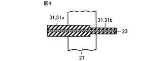
- FIG. 4 is a sectional view taken along a sectional line IV-IV shown in FIG. 3 in the embodiment.
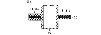
- FIG. 5 is a sectional view taken along a sectional line VV shown in FIG. 3 in the embodiment.
- FIG. 6 is a partial plan view showing a fin on which an adsorbent is applied in a heat exchanger according to a comparative example.
- FIG. 3 is a partial plan view showing the fins to which the adsorbent is applied in the heat exchanger according to the first embodiment.
- FIG. 4 is a sectional view taken along a sectional line IV-IV shown in FIG. 3 in the embodiment.
- FIG. 5 is a sectional view taken along a sectional line VV shown in FIG. 3 in the embodiment.
- FIG. 6 is a partial plan view showing a fin on which an adsorbent is applied in
- FIG. 7 is a sectional view taken along section line VII-VII shown in FIG. 6.
- FIG. 7 is a sectional view taken along section line VIII-VIII shown in FIG. 6.
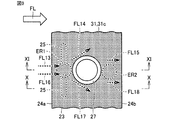
- FIG. 13 is a partial plan view showing fins to which an adsorbent has been applied in the heat exchanger according to Embodiment 2.
- FIG. 10 is a cross sectional view taken along a cross sectional line XX shown in FIG. 9 in the embodiment.
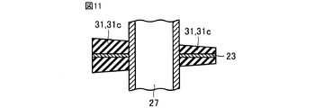
- FIG. 10 is a cross sectional view taken along a cross sectional line XI-XI shown in FIG. 9 in the embodiment.
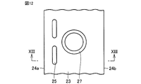
- FIG. 3 is a partial plan view showing the fin before an adsorbent is applied in the embodiment.
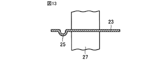
- FIG. 13 is a cross sectional view taken along a cross sectional line XIII-XIII shown in FIG. 12 in the embodiment.
- FIG. 10 is a perspective view of a heat exchanger according to Embodiment 3.
- FIG. 3 is a partial plan view showing the fin on which the adsorbent is applied in the embodiment.
- FIG. 16 is a cross sectional view taken along a cross sectional line XVI-XVI shown in FIG. 15 in the embodiment.
- FIG. 17 is a cross-sectional view taken along a cross-sectional line XVII-XVII shown in FIG. 15 in the embodiment.
- FIG. 13 is a perspective view illustrating one step of a method for manufacturing a heat exchanger according to Embodiment 4.
- FIG. 4 is a perspective view illustrating one step of a method for manufacturing a heat exchanger according to Embodiment 4.
- FIG. 19 is a perspective view showing a step performed after the step shown in FIG. 18 in the embodiment.
- FIG. 20 is a perspective view showing a step performed after the step shown in FIG. 19 in the embodiment.
- FIG. 3 is a partial plan view showing the fin on which the adsorbent is applied in the embodiment.
- FIG. 22 is a cross sectional view taken along a cross sectional line XXII-XXII shown in FIG. 21 in the embodiment.
- FIG. 22 is a sectional view taken along a sectional line XXIII-XXIII shown in FIG. 21 in the embodiment.
- it is a partial plan view showing a fin to which an adsorbent is applied in a heat exchanger according to a modification.
- FIG. 25 is a sectional view taken along section line XXV-XXV shown in FIG. 24.
- FIG. 15 is a partial plan view showing fins to which an adsorbent is applied in a heat exchanger according to another modification in each embodiment.
- FIG. 27 is a sectional view taken along section line XXVII-XXVII shown in FIG. 26.
- the refrigeration cycle apparatus 1 includes a compressor 3, an indoor heat exchanger 5, an indoor fan 7, an expansion valve 9, an outdoor heat exchanger 11, an outdoor fan 13, and a four-way valve 15.
- the compressor 3, the indoor heat exchanger 5, the expansion valve 9, the outdoor heat exchanger 11, and the four-way valve 15 are connected by a refrigerant pipe 17.
- the outdoor heat exchanger 11 will be described as an example of the heat exchanger according to each embodiment.
- a plurality of fins 23 are arranged at intervals as the first fin or the second fin, and penetrate through the plurality of fins 23.
- the heat transfer tube 27 as the first heat transfer tube or the second heat transfer tube is inserted.
- the heat transfer tubes 27 are arranged at intervals in the direction in which the fins 23 extend.
- the surface of each fin 23 is coated with an adsorbent as a first adsorbent or a second adsorbent that adsorbs moisture (moisture, water vapor) in the air.
- the adsorbent will be specifically described later as including an adhesive.
- a high-temperature and high-pressure gas refrigerant is discharged from the compressor 3.
- the discharged high-temperature and high-pressure gas refrigerant flows into the indoor heat exchanger 5 via the four-way valve 15.
- heat exchange is performed between the gas refrigerant that has flowed in and the air supplied by the indoor fan 7.
- the high-temperature and high-pressure gas refrigerant condenses into a high-pressure liquid refrigerant (single phase). This heat exchange heats the room.
- the high-pressure liquid refrigerant sent from the indoor heat exchanger 5 is turned into a two-phase refrigerant of a low-pressure gas refrigerant and a liquid refrigerant by the expansion valve 9.
- the two-phase refrigerant flows into the outdoor heat exchanger 11.
- the outdoor heat exchanger 11 functions as an evaporator. In the outdoor heat exchanger 11, heat exchange is performed between the two-phase refrigerant that has flowed in and the air supplied by the outdoor fan 13. Among the refrigerants in the two-phase state, the liquid refrigerant evaporates to become a low-pressure gas refrigerant (single phase).
- the low-pressure gas refrigerant sent from the outdoor heat exchanger 11 flows into the compressor 3 via the four-way valve 15.
- the low-pressure gas refrigerant flowing into the compressor 3 is compressed into a high-temperature and high-pressure gas refrigerant, and is discharged from the compressor 3 again. Hereinafter, this cycle is repeated.
- a high-temperature and high-pressure gas refrigerant is discharged from the compressor 3.
- the discharged high-temperature and high-pressure gas refrigerant flows into the outdoor heat exchanger 11 via the four-way valve 15.
- the outdoor heat exchanger 11 functions as a condenser.
- heat exchange is performed between the flowing refrigerant and air supplied by the outdoor fan 13.
- the high-temperature and high-pressure gas refrigerant condenses into a high-pressure liquid refrigerant (single phase).
- the high-pressure liquid refrigerant sent from the outdoor heat exchanger 11 is turned into a two-phase refrigerant of a low-pressure gas refrigerant and a liquid refrigerant by the expansion valve 9.
- the refrigerant in the two-phase state flows into the indoor heat exchanger 5.
- heat exchange is performed between the two-phase refrigerant that has flowed in and the air supplied by the indoor fan 7.
- the liquid refrigerant evaporates to become a low-pressure gas refrigerant (single phase). This heat exchange cools the room.
- the low-pressure gas refrigerant sent from the indoor heat exchanger 5 flows into the compressor 3 via the four-way valve 15.
- the low-pressure gas refrigerant flowing into the compressor 3 is compressed into a high-temperature and high-pressure gas refrigerant, and is discharged from the compressor 3 again.
- this cycle is repeated.
- Embodiment 1 FIG. As shown in FIGS. 2 and 3, in the heat exchanger 21, a plurality of fins 23 are arranged at a distance from each other. Each fin 23 has a first end 24a and a second end 24b facing each other at a distance in the width direction (first direction), and extends in a direction (second direction) intersecting the width direction. It extends like a band.
- an adsorbent 31 is applied (formed) on each surface of the plurality of fins 23.
- An adsorbent 31a as a first part of the first adsorbent is applied to a region ER1 as a first part of the fin 23 from the first end 24a to the heat transfer tube 27.
- an adsorbent 31b as a first adsorbent second portion is applied.
- the adsorbent 31b is applied with a thickness smaller than the thickness of the adsorbent 31a.
- the adsorbent 31 for example, silica gel and epoxy resin are used.
- the heat exchanger 21 in which the fins 23 are coated with the adsorbent 31 is also called an adsorption / desorption heat exchanger.
- the wind speeds of the air flows FL3 and FL6 are smaller than the wind speeds of the air flows FL1, FL4, FL2, and FL5 flowing through the portion of the fins 23 (region ER1) located on the windward side with respect to the heat transfer tube 27. . Accordingly, the amount of moisture (water vapor amount) sent to the fins 23 located on the leeward side by air is smaller than the amount of moisture sent to the fins 23 located on the leeward side.
- the adsorbent 31 has a uniform thickness from the first end 24a to the second end 24b of the fin 23. It is formed with.
- the air sent into the heat exchanger 21 flows from the first end 24a toward the heat transfer tube 27 (air flows FL7, FL10).
- the air flows around the heat transfer tubes 27 the air flows FL8 and FL11.
- the air flows toward the second end 24b air flows FL9, FL12).
- the adsorbent 31 is formed with a uniform thickness from the first end 24a to the second end 24b of the fin 23. Therefore, the amount of moisture (moisture and water vapor) that can be adsorbed in the fin 23 located on the leeward side (region ER2) is the amount of moisture that can be adsorbed in the fin 23 located on the leeward side (region ER1). On the other hand, the amount of moisture (the amount of moisture and the amount of water vapor) that can be actually adsorbed is small, while the amount of moisture (the amount of moisture and the amount of water vapor) that can be actually adsorbed is small. Is excessively applied.
- the adsorbent 21 is formed in a portion (region ER2) of the fin 23 located on the leeward side with respect to the heat transfer tube 27.
- 31b is formed with a thickness smaller than the thickness of the adsorbent 31a formed in the portion of the fin 23 (region ER1) located on the windward side with respect to the heat transfer tube 27.
- the adsorbent 31b corresponding to the small amount of moisture (the amount of moisture and the amount of water vapor) is applied to the portion of the fins 23 (region ER2) located on the leeward side where the amount of moisture sent is smaller than that on the leeward side. Will be.
- the cost of applying the adsorbent 31 excessively can be suppressed, which can contribute to a reduction in the production cost of the heat exchanger 21.
- FIG. 1 A heat exchanger according to Embodiment 2 will be described.
- the portion of the adsorbent 31 c formed in the portion of the fin 23 (region ER ⁇ b> 2) located on the leeward side with respect to the heat transfer tube 27 is The fin 23 is formed with a thickness smaller than the thickness of the portion of the adsorbent 31c formed in the portion of the fin 23 (region ER1) located on the windward side.
- the thickness of the adsorbent 31c (31) gradually decreases from the first end 24a of the fin 23 to the second end 24b via the heat transfer tube 27. It is formed as follows.
- the other components are the same as those of the heat exchangers shown in FIGS. 2 and 3 and the like, and the same members are denoted by the same reference characters and description thereof will not be repeated unless necessary.
- the air sent into the heat exchanger 21 flows from the first end 24a toward the heat transfer tube 27 (air flows FL13, FL16).
- the air flows around the heat transfer tube 27 air flows FL14, FL17).
- the air flows toward the second end 24b air flows FL15, FL18).
- the wind speed of the air flows FL15 and FL18 on the leeward side with respect to the heat transfer tube 27 is smaller than the wind speed of the air flows FL13, FL16, FL14 and FL17 on the leeward side with respect to the heat transfer tube 27.
- the adsorbent 31c (31) is formed such that the thickness gradually decreases from the first end 24a of the fin 23 to the second end 24b via the heat transfer tube 27. ing.
- the thickness of the portion of the adsorbent 31c formed in the portion (region ER2) of the fin 23 located on the leeward side with respect to the heat transfer tube 27 is the portion of the fin 23 located on the leeward side of the heat transfer tube 27 ( The thickness is smaller than the thickness of the portion of the adsorbent 31c formed in the region ER1).
- the adsorbent 31b corresponding to (moisture content, water vapor content) is applied.
- the cost of applying the adsorbent 31 excessively can be suppressed, which can contribute to a reduction in the production cost of the heat exchanger 21.
- the adsorbent By the way, when moisture (moisture, water vapor) in the air is adsorbed by the adsorbent, the adsorbent generates heat.
- the fins 23 on the windward side to which more water (moisture and water vapor) is sent than the leeward side are coated with a thicker adsorbent 31c to adsorb the water (moisture and water vapor). I have. Therefore, the calorific value of the adsorbent 31c is larger on the windward side than on the leeward side.
- the fins 23 are provided with the depressions 25.
- the depression 25 is formed in a portion of the fin 23 located on the windward side with respect to the heat transfer tube 27.
- an adsorbent 31c is applied so as to cover the depression 25.
- the contact area between the adsorbent 31c and the fins 23 is increased as compared with the case where there is no depression.
- the heat generated by the adsorbent 31c can be efficiently conducted to the fins 23 to remove the heat.
- the adsorption of moisture (moisture, water vapor) by the adsorbent 31c located on the windward side is promoted, and the dehumidification performance can be improved.
- the adsorbent 31c is applied with a thickness that does not reflect the surface shape of the fin 23 in which the depression 25 is formed so that the surface of the adsorbent 31c does not have irregularities. Thereby, conduction of the heat generated in the adsorbent 31c into the air can be suppressed, and an excessive rise in the temperature of the air after dehumidification can be prevented. As a result, comfort can be improved.
- the fins 23 are not limited to the depressions 25 as long as the contact area between the fins 23 and the adsorbent 31 can be increased.
- corrugated fins may be applied.
- the heat exchanger 21 includes a first heat exchanger 21a, a second heat exchanger 21b, and a third heat exchanger 21c.
- the first heat exchanger 21a includes a plurality of first fins 23a and a heat transfer tube 27 as a first heat transfer tube.
- the second heat exchanger 21b includes a plurality of second fins 23b and a heat transfer tube 27 as a second heat transfer tube.
- the third heat exchanger 21c includes a plurality of third fins 23c and a heat transfer tube 27.
- first heat exchanger 21a In each of the first heat exchanger 21a, the second heat exchanger 21b, and the third heat exchanger 21c, a plurality of fins 23 are arranged at an interval from each other, and the heat transfer tubes extend through the plurality of fins 23. 27 is inserted.
- the heat transfer tubes 27 are arranged at intervals in the direction in which the fins 23 extend.
- the first heat exchanger 21a is arranged in the first row from the windward side
- the second heat exchanger 21b is arranged in the second row
- the third heat exchanger 21c is arranged in the third row. .
- an adsorbent 31 is applied to each surface of the plurality of first fins 23a in the first row.
- An adsorbent 31a is applied to a first portion (region ER1) of the first fin 23a extending from the first end 24a to the heat transfer tube 27.
- An adsorbent 31b is applied to a second portion (region ER2) of the first fin 23a from the heat transfer tube 27 to the second end 24b.
- the adsorbent 31b is applied with a thickness smaller than the thickness of the adsorbent 31a.
- the adsorbent 31 is applied to each surface of the second fins 23b in the second row.
- the first portion (region ER3) of the second fin 23b extending from the third end 24c to the heat transfer tube 27 is coated with an adsorbent 31d as a second portion of the second adsorbent.
- An adsorbent 31f as a second adsorbent second part is applied to a second portion (region ER4) of the second fin 23b from the heat transfer tube 27 to the fourth end 24d.
- An adsorbent 31e is applied to the remaining portion of the second fin 23b.
- the adsorbents 31d and 31f are applied with a thickness smaller than the thickness of the adsorbent 31a applied to the first fin 23a.
- the adsorbent 31 is applied to each surface of the third fins 23c in the third row.
- An adsorbent 31g is applied to a first portion (region ER5) of the third fin 23c from the fifth end 24e to the heat transfer tube 27.
- An adsorbent 31i is applied to a second portion (region ER6) of the third fin 23c from the heat transfer tube 27 to the sixth end 24f.
- An adsorbent 31h is applied to the remaining portion of the third fin 23c.
- the adsorbents 31g and 31i are applied with a thickness smaller than the thickness of the adsorbent 31a applied to the first fin 23a.
- the air sent into the heat exchanger 21 first flows through the first heat exchanger 21a.
- the air flows from the side of the first end 24a of the first fin 23a toward the heat transfer tube 27 (air flows FL19, FL22).
- the air flows around the heat transfer tubes 27 (air flows FL20, FL23).
- the air flows toward the second end 24b (air flows FL21, FL24).
- the air that has flowed through the first heat exchanger 21a then flows through the second heat exchanger 21b.
- the air flows from the third end 24c of the second fin 23b toward the heat transfer tube 27 (air flows FL25, FL28).
- the air flows around the heat transfer tube 27 (air flows FL26, FL29).
- the air flows toward the fourth end 24d (air flows FL27, FL30).
- the air flows from the fifth end 24e of the third fin 23c toward the heat transfer tube 27 (air flows FL31, FL34).
- the air flows around the heat transfer tube 27 (air flows FL32, FL35).
- the air flows toward the sixth end 24f (air flows FL34, FL36).
- the heat transfer tubes 27 of the first heat exchanger 21a, the second heat exchanger 21b, and the third heat exchanger 21c are arranged along the direction in which air flows.
- the flow of air is hindered by the heat transfer tube 27 in the portion (region ER2) of the first fin 23a located on the leeward side of the heat transfer tube 27.
- the wind speed of the air flow FL21, FL24 on the leeward side of the heat transfer tube 27 is smaller than the wind speed of the air flow FL19, FL22, FL20, FL23 on the leeward side of the heat transfer tube 27.
- the second heat exchanger 21b and the third heat exchanger 21c are affected by the heat transfer tubes 27 of the first heat exchanger 21a located on the windward side (wind path resistance). Therefore, in the second heat exchanger 21b, the wind speeds of the air flows FL25 and FL28 on the leeward side of the second fins 23b and the wind speeds of the air flows FL27 and FL30 on the leeward side are equal to those of the first heat exchanger 21a. It becomes smaller than the wind speed of the airflow FL19, FL22, FL20, FL23 on the windward side.
- the wind speeds of the air flows FL31 and FL34 on the windward side of the third fin 23c and the wind speeds of the air flows FL34 and FL36 on the leeward side correspond to the wind speed of the first heat exchanger 21a. It becomes smaller than the wind speed of the upper air flow FL19, FL22, FL20, FL23.
- the thickness of the adsorbent 31f applied to the portion (region ER4) of the second fin 23b located at is smaller than the thickness of the adsorbent 31a applied to the first fin 23a.
- the thickness of the adsorbent 31g applied to the portion (region ER5) of the third fin 23c located on the windward side with respect to the heat transfer tube 27 of the third heat exchanger 21c, and the third fin located on the leeward side is smaller than the thickness of the adsorbent 31a applied to the first fin 23a.
- the second heat exchange located on the leeward side where the amount of moisture (the amount of moisture and the amount of water vapor) sent is smaller than the leeward side of the first heat exchanger 21a.
- the portions of the second fins 23b of the heat exchanger 21b (regions ER3 and ER4) and the portions of the third fins 23c of the third heat exchanger 21c (regions ER5 and ER6) correspond to the small amounts of moisture (moisture and water vapor).
- the adsorbents 31d, 31f, 31g, and 31i are applied.
- the cost due to excessive application of the adsorbent 31 can be suppressed, which can contribute to a reduction in the production cost of the heat exchanger 21.
- Embodiment 4 FIG. In the fourth embodiment, an example of a process of applying an adsorbent to a fin in which a heat transfer tube is inserted will be described in a series of manufacturing processes of a heat exchanger.
- a chemical solution 45 containing an adsorbent is stored in the container 43 of the coating device 41.
- the adsorbent also includes an adhesive, and for example, silica gel and epoxy resin are used.
- the heat exchanger 21 in the middle of assembly, in which the heat transfer tubes 27 are inserted through the fins 23, is arranged.
- the heat exchanger 21 is lowered toward the container 43 (chemical solution 45), and as shown in FIG. 19, the heat exchanger 21 is immersed in the chemical solution 45 with the longitudinal direction of the fins 23 being horizontal.
- the heat exchanger 21 manufactured by the above-described manufacturing method is arranged such that the lower first end 24a on which the sorbent 31 is more applied, is located on the windward side.
- the portion of the fins 23 located on the leeward side where the amount of moisture (the amount of moisture and the amount of water vapor) sent is smaller than that on the leeward side, the less moisture It means that the adsorbent 31b corresponding to the amount (moisture amount, water vapor amount) is applied.
- the cost due to excessive application of the adsorbent 31 is suppressed, which can contribute to a reduction in production cost.
- the adsorbent 31 b formed in the portion of the fin 23 located on the leeward side with respect to the heat transfer tube 27 is the fin located on the windward side with respect to the heat transfer tube 27. What is necessary is just to form with the thickness thinner than the thickness of the adsorbent 31a formed in the part 23.
- an adsorbent 31a is applied on the windward side and an adsorbent 31b is applied on the leeward side in such a manner that the width direction of the fin 23 is bisected with the vicinity of the center of the heat transfer tube 27 as a boundary.
- the applied heat exchanger 21 may be used.
- the adsorbent 31b is applied to the area of the fins 23 behind the heat transfer tube 27 when viewed from the windward side, and the adsorbent 31a is applied to the other areas of the fins 23.
- Heat exchanger 21 may be used.
- the heat exchanger 21 according to each embodiment described above is applied to an outdoor heat exchanger, but may be applied to an indoor heat exchanger.
- the present invention is effectively used for a heat exchanger having fins coated with an adsorbent.
- 1 refrigeration cycle device 3 compressor, 5 indoor heat exchanger, 7 indoor fan, 9 expansion valve, 11 outdoor heat exchanger, 13 outdoor fan, 15 four-way valve, 17 refrigerant pipe, 21 heat exchanger, 21a first heat Heat exchanger, 21b second heat exchanger, 21c third heat exchanger, 23, fin, 23a first fin, 23b second fin, 23c third fin, 24a first end, 24b second end, 24c first 3 end, 24d ⁇ fourth end, 24e ⁇ fifth end, 24f ⁇ sixth end, 24g ⁇ first end, 24h ⁇ second end, 25 ⁇ depression, 27 ⁇ heat transfer tube, 31, 31a, 31b, 31c, 31d , 31e, 31f, 31g, 31h, 31i ⁇ Adsorbent, 41 ⁇ Coating device, 43 # Container, 45 # Chemical solution, ER1, ER2, ER3, ER4, ER5, ER6 ⁇ region, FL, FL ⁇ FL36 air flow, GR arrow.
Landscapes
- Engineering & Computer Science (AREA)
- Physics & Mathematics (AREA)
- Mechanical Engineering (AREA)
- Thermal Sciences (AREA)
- General Engineering & Computer Science (AREA)
- Geometry (AREA)
- Heat-Exchange Devices With Radiators And Conduit Assemblies (AREA)
Abstract
熱交換器(21)では、複数のフィン(23)が互いに距離を隔てて配置されている。それぞれのフィン(23)は、互いに幅方向に距離を隔てて対向する第1端部(24a)と第2端部(24b)とを有して、幅方向と交差する方向に帯状に延在している。複数のフィン(23)のそれぞれの表面に、吸着剤(31)が塗布されている。第1端部(24a)から伝熱管(27)に至るフィン(23)の部分には、吸着剤(31a)が塗布されている。伝熱管(27)から第2端部(24b)に至るフィン(23)の部分には、吸着剤(31b)が塗布されている。吸着剤(31b)は、吸着剤(31a)の厚さよりも薄い厚さをもって塗布されている。
Description
本発明は、熱交換器および冷凍サイクル装置ならびに熱交換器の製造方法に関し、特に、吸着剤が塗布された熱交換器と、そのような熱交換器を備えた冷凍サイクル装置と、熱交換器の製造方法とに関する。
従来より、空気中の水分(湿分、水蒸気)を吸着する吸着剤がフィンの表面に塗布(担持)された熱交換器が知られている。たとえば、特許文献1では、接着剤を含有した吸水作用を有する吸着剤が、フィンおよび伝熱管の表面に接着されている冷凍機が提案されている。
この種の熱交換器に使用されている吸着剤は、基本的には、吸着剤の温度が低くなると水分の吸着量が多くなり、吸着剤の温度が高くなると水分の吸着量は少なくなる特性を有する。また、吸着剤が水分を吸収する際には熱が発生し、吸着剤の温度が上昇することになる。このため、単位時間当たりの水分の吸着量を増大させるには、吸着剤を効率的に冷却する必要がある。特許文献1に開示された熱交換器では、吸着剤を効率的に冷却するために、伝熱管に近いフィンの部分には吸着剤は厚く塗布され、伝熱管から遠いフィンの部分には吸着剤は薄く塗布されている。
しかしながら、従来の熱交換器では、次のような課題がある。熱交換器を動作させると、熱交換器に空気が送り込まれて、伝熱管が挿通されたフィンとフィンとの間を空気が流れて、伝熱管を流れる冷媒等と空気との間で熱交換が行われる。このとき、伝熱管の風下側に位置するフィンの部分を流れる風速は、伝熱管の風上側に位置するフィンの部分を流れる風速よりも小さくなる。
このため、伝熱管の風下側に位置するフィンの部分に塗布される吸着剤の量が多いと、流れる空気によって送り込まれる水分量(湿分量、水蒸気量)に対して、吸着剤の量が過剰になる。その結果、その分、熱交換器の生産コストが上昇することになる。
本発明は、上記問題点を解決するためになされたものであり、一つの目的は、生産コストの低減に寄与できる熱交換器を提供することであり、他の目的は、そのような熱交換器を備えた冷凍サイクル装置を提供することであり、さらに他の目的は、熱交換器の製造方法を提供することである。
本発明に係る熱交換器は、第1フィンと第1伝熱管と第1吸着剤とを備えている。第1フィンは、第1方向に距離を隔てて対向する第1端部と第2端部とを有し、第1方向と交差する第2方向に延在する。第1伝熱管は、第1端部と第2端部との間に位置する第1フィンの部分に挿通されている。第1吸着剤は、第1フィンに形成されている。その第1吸着剤は、第1吸着剤第1部と第1吸着剤第2部とを含む。第1吸着剤第1部は、第1端部から第1伝熱管に至る第1フィンの第1部分に形成されている。第1吸着剤第2部は、第1伝熱管から第2端部に至る第1フィンの第2部分に形成されている。第1吸着剤第2部の厚さは、第1吸着剤第1部の厚さよりも薄い。
本発明に係る冷凍サイクル装置は、上述した熱交換器を備えた冷凍サイクル装置である。
本発明に係る熱交換器の製造方法は、伝熱管が挿通されたフィンに吸着剤を塗布する工程を備えた熱交換器の製造方法である。吸着剤を塗布する工程は、以下の工程を備えている。吸着剤が貯留された薬液槽を用意する。伝熱管が挿通されたフィンを、フィンが延在する方向を水平にして薬液槽に貯留された吸着剤に浸漬する。フィンを薬液槽から引き上げて、フィンが延在する方向を水平にした状態で保持する。
本発明に係る熱交換器によれば、第1フィンに形成された第1吸着剤は、第1端部から第1伝熱管に至る第1フィンの第1部分に形成されている第1吸着剤第1部と、第1伝熱管から第2端部に至る第1フィンの第2部分に形成されている第1吸着剤第2部とを含み、第1吸着剤第2部の厚さは、第1吸着剤第1部の厚さよりも薄い。これにより、風上側に比べて、空気から送り込まれる湿分量が少ない風下側に位置する第1フィンの部分では、その少ない湿分量に対応した第1吸着剤第2部が形成されていることになる。その結果、第1吸着剤を過剰に塗布することによるコストが抑えられて、生産コストの低減に寄与することができる。
本発明に係る冷凍サイクル装置によれば、上述した熱交換器を適用することで、生産コストの低減に寄与することができる。
本発明に係る熱交換器の製造方法によれば、熱交換器の生産コストの低減に寄与することができる。
はじめに、各実施の形態に係る熱交換器を適用した冷凍サイクル装置の一例について説明する。図1に示すように、冷凍サイクル装置1は、圧縮機3、室内熱交換器5、室内ファン7、膨張弁9、室外熱交換器11、室外ファン13および四方弁15を備えている。圧縮機3、室内熱交換器5、膨張弁9、室外熱交換器11および四方弁15は、冷媒配管17によって繋がっている。
各実施の形態に係る熱交換器の一例として、室外熱交換器11について説明する。図2に示すように、室外熱交換器11としての熱交換器21では、第1フィンまたは第2フィンとしての互いに間隔を隔てて複数のフィン23が配置され、その複数のフィン23を貫通するように、第1伝熱管または第2伝熱管としての伝熱管27が挿通されている。伝熱管27は、フィン23が延在する方向に互いに間隔を隔てて配置されている。後述するように、それぞれのフィン23の表面には、空気中の水分(湿分、水蒸気)を吸着する第1吸着剤または第2吸着剤としての吸着剤が塗布されている。この明細書では、吸着剤は接着剤を含むものとして、後で具体的に説明する。
次に、上述した冷凍サイクル装置1の動作として、まず、暖房運転の場合について説明する。圧縮機3を駆動させることによって、圧縮機3から高温高圧のガス冷媒が吐出する。吐出した高温高圧のガス冷媒(単相)は、四方弁15を介して室内熱交換器5に流れ込む。室内熱交換器5では、流れ込んだガス冷媒と、室内ファン7によって供給される空気との間で熱交換が行われる。高温高圧のガス冷媒は、凝縮して高圧の液冷媒(単相)になる。この熱交換によって、室内が暖房されることになる。室内熱交換器5から送り出された高圧の液冷媒は、膨張弁9によって、低圧のガス冷媒と液冷媒との二相状態の冷媒になる。
二相状態の冷媒は、室外熱交換器11に流れ込む。室外熱交換器11は、蒸発器として機能する。室外熱交換器11では、流れ込んだ二相状態の冷媒と、室外ファン13によって供給される空気との間で熱交換が行われる。二相状態の冷媒のうち、液冷媒が蒸発して、低圧のガス冷媒(単相)になる。室外熱交換器11から送り出された低圧のガス冷媒は、四方弁15を介して圧縮機3に流れ込む。圧縮機3に流れ込んだ低圧のガス冷媒は、圧縮されて高温高圧のガス冷媒となって、再び圧縮機3から吐出する。以下、このサイクルが繰り返される。
次に、冷房運転の場合について説明する。圧縮機3を駆動させることによって、圧縮機3から高温高圧のガス冷媒が吐出する。吐出した高温高圧のガス冷媒(単相)は、四方弁15を介して室外熱交換器11へ流れ込む。室外熱交換器11は、凝縮器として機能する。室外熱交換器11では、流れ込んだ冷媒と、室外ファン13によって供給される空気との間で熱交換が行われる。高温高圧のガス冷媒は、凝縮して高圧の液冷媒(単相)になる。
室外熱交換器11から送り出された高圧の液冷媒は、膨張弁9によって、低圧のガス冷媒と液冷媒との二相状態の冷媒になる。二相状態の冷媒は、室内熱交換器5に流れ込む。室内熱交換器5では、流れ込んだ二相状態の冷媒と、室内ファン7によって供給される空気との間で熱交換が行われる。二相状態の冷媒は、液冷媒が蒸発して低圧のガス冷媒(単相)になる。この熱交換によって、室内が冷却されることになる。室内熱交換器5から送り出された低圧のガス冷媒は、四方弁15を介して圧縮機3に流れ込む。圧縮機3に流れ込んだ低圧のガス冷媒は、圧縮されて高温高圧のガス冷媒となって、再び圧縮機3から吐出する。以下、このサイクルが繰り返される。
次に、上述した冷凍サイクル装置1における室外熱交換器11として適用されている熱交換器について、具体的に説明する。
実施の形態1.
図2および図3に示すように、熱交換器21では、複数のフィン23が互いに距離を隔てて配置されている。それぞれのフィン23は、互いに幅方向(第1方向)に距離を隔てて対向する第1端部24aと第2端部24bとを有して、幅方向と交差する方向(第2方向)に帯状に延在している。
図2および図3に示すように、熱交換器21では、複数のフィン23が互いに距離を隔てて配置されている。それぞれのフィン23は、互いに幅方向(第1方向)に距離を隔てて対向する第1端部24aと第2端部24bとを有して、幅方向と交差する方向(第2方向)に帯状に延在している。
図3に示すように、その複数のフィン23のそれぞれの表面には、吸着剤31が塗布(形成)されている。第1端部24aから伝熱管27に至るフィン23の第1部分としての領域ER1には、第1吸着剤第1部としての吸着剤31aが塗布されている。伝熱管27から第2端部24bに至るフィン23の第2部分としての領域ER2には、第1吸着剤第2部としての吸着剤31bが塗布されている。図4および図5に示すように、吸着剤31bは、吸着剤31aの厚さよりも薄い厚さをもって塗布されている。吸着剤31として、たとえば、シリカゲルとエポキシ系樹脂が使用される。なお、フィン23に吸着剤31が塗布された熱交換器21は、吸脱着熱交換器とも呼ばれる。
次に、熱交換器21が稼働している状態での、フィン23とフィン23との間を流れる空気の流れについて説明する。室外ファン13(図1参照)により、フィン23の第1端部24a側から第2端部24b側に向かって空気が流れているとする。この場合、フィン23の第1端部24aが風上側に位置し、第2端部24bが風下側に位置することになる。
熱交換器21に送り込まれた空気は、第1端部24aの側から伝熱管27に向かって流れる(空気の流れFL1、FL4)。次に、伝熱管27の周辺を流れる(空気の流れFL2、FL5)。その後、第2端部24bの側に向かって流れる(空気の流れFL3、FL6)。伝熱管27に対して風下側に位置するフィン23の部分(領域ER2)では、伝熱管27によって空気の流れが阻害されることになる。
このため、空気の流れFL3、FL6の風速は、伝熱管27に対して風上側に位置するフィン23の部分(領域ER1)を流れる空気の流れFL1、FL4、FL2、FL5の風速よりも小さくなる。これにより、空気によって風下側に位置するフィン23の部分に送り込まれる湿分量(水蒸気量)は、風上側に位置するフィン23の部分に送り込まれる湿分量よりも少なくなる。
ここで、比較例として、吸着剤が一様な厚さをもってフィンに塗布された熱交換器について説明する。なお、説明の便宜上、実施の形態に係る熱交換器と同一部材については、同一符号を付し、必要である場合を除きその説明を繰り返さないこととする。
図6、図7および図8に示すように、比較例に係る熱交換器のフィン23では、フィン23の第1端部24aから第2端部24bにわたり、吸着剤31は、一様な厚さをもって形成されている。
次に、フィン23とフィン23との間を流れる空気の流れについて説明する。空気の流れる方向は、図3に示す方向と同じ方向とする。図6に示すように、熱交換器21に送り込まれた空気は、第1端部24aの側から伝熱管27に向かって流れる(空気の流れFL7、FL10)。次に、伝熱管27の周辺を流れる(空気の流れFL8、FL11)。その後、第2端部24bの側に向かって流れる(空気の流れFL9、FL12)。
伝熱管27に対して風下側に位置するフィン23の部分(領域ER2)では、伝熱管27によって空気の流れが阻害されることになる。このため、風下側の空気の流れFL9、FL12の風速は、風上側の空気の流れFL7、FL10、FL8、FL11の風速よりも小さくなり、風下側に位置するフィン23の部分(領域ER2)に送り込まれる水分量(湿分量、水蒸気量)は、風上側に位置するフィン23の部分(領域ER1)に送り込まれる水分量(湿分量、水蒸気量)よりも少なくなる。
ところが、フィン23の第1端部24aから第2端部24bにわたり、吸着剤31は、一様な厚さをもって形成されている。このため、風下側に位置するフィン23の部分(領域ER2)における吸着可能な水分量(湿分量、水蒸気量)は、風上側に位置するフィン23の部分(領域ER1)における吸着可能な水分量(湿分量、水蒸気量)と同じであるの対して、実際に吸着し得る水分量(湿分量、水蒸気量)は少なく、風下側に位置するフィン23の部分(領域ER2)では、吸着剤31が過剰に塗布されていることになる。
比較例に係る熱交換器に対して、実施の形態1に係る熱交換器で21は、伝熱管27に対して風下側に位置するフィン23の部分(領域ER2)に形成されている吸着剤31bは、伝熱管27に対して風上側に位置するフィン23の部分(領域ER1)に形成されている吸着剤31aの厚さよりも薄い厚さをもって形成されている。
これにより、風上側に比べて送り込まれる湿分量が少ない風下側に位置するフィン23の部分(領域ER2)では、その少ない水分量(湿分量、水蒸気量)に対応した吸着剤31bが塗布されていることになる。その結果、吸着剤31を過剰に塗布することによるコストが抑えられて、熱交換器21の生産コストの低減に寄与することができる。
実施の形態2.
実施の形態2に係る熱交換器について説明する。図9、図10および図11に示すように、伝熱管27に対して風下側に位置するフィン23の部分(領域ER2)に形成されている吸着剤31cの部分は、伝熱管27に対して風上側に位置するフィン23の部分(領域ER1)に形成されている吸着剤31cの部分の厚さよりも薄い厚さをもって形成されている。
実施の形態2に係る熱交換器について説明する。図9、図10および図11に示すように、伝熱管27に対して風下側に位置するフィン23の部分(領域ER2)に形成されている吸着剤31cの部分は、伝熱管27に対して風上側に位置するフィン23の部分(領域ER1)に形成されている吸着剤31cの部分の厚さよりも薄い厚さをもって形成されている。
この熱交換器21(図2参照)では、吸着剤31c(31)は、フィン23の第1端部24aから伝熱管27を経て第2端部24bに向かって、厚さが徐々に薄くなるように形成されている。なお、これ以外の構成については、図2および図3等に示す熱交換器と同様なので、同一部材には同一符号を付し、必要である場合を除きその説明を繰り返さないこととする。
次に、フィン23とフィン23との間を流れる空気の流れについて説明する。図9に示すように、熱交換器21に送り込まれた空気は、第1端部24aの側から伝熱管27に向かって流れる(空気の流れFL13、FL16)。次に、空気は伝熱管27の周辺を流れる(空気の流れFL14、FL17)。その後、空気は第2端部24bの側に向かって流れる(空気の流れFL15、FL18)。
前述したように、伝熱管27に対して風下側に位置するフィン23の部分(領域ER2)では、伝熱管27によって空気の流れが阻害されることになる。このため、伝熱管27に対して風下側の空気の流れFL15、FL18の風速は、伝熱管27に対して風上側の空気の流れFL13、FL16、FL14、FL17の風速よりも小さくなる。
上述した熱交換器21では、吸着剤31c(31)は、フィン23の第1端部24aから伝熱管27を経て第2端部24bに向かって、厚さが徐々に薄くなるように形成されている。伝熱管27に対して風下側に位置するフィン23の部分(領域ER2)に形成されている吸着剤31cの部分の厚さは、伝熱管27に対して風上側に位置するフィン23の部分(領域ER1)に形成されている吸着剤31cの部分の厚さよりも薄い。
これにより、実施の形態1において説明したように、風上側に比べて送り込まれる水分量(湿分量、水蒸気量)が少ない風下側に位置するフィン23の部分(領域ER2)では、その少ない水分量(湿分量、水蒸気量)に対応した吸着剤31bが塗布されていることになる。その結果、吸着剤31を過剰に塗布することによるコストが抑えられて、熱交換器21の生産コストの低減に寄与することができる。
ところで、空気中の水分(湿分、水蒸気)が吸着剤に吸着すると、吸着剤は発熱をする。風下側に比べてより多くの水分(湿分、水蒸気)が送り込まれる風上側のフィン23の部分では、その水分(湿分、水蒸気)を吸着するために、より厚い吸着剤31cが塗布されている。このため、風上側では、風下側に比べて吸着剤31cの発熱量が多くなる。
図12および図13に示すように、上述した熱交換器21では、フィン23に窪み25が設けられている。窪み25は、伝熱管27に対して風上側に位置するフィン23の部分に形成されている。熱交換器21では、この窪み25を覆うように吸着剤31cが塗布されている。
このため、窪みがない場合と比べて、吸着剤31cとフィン23との接触面積が増えることになる。これにより、吸着剤31cで発生した熱をフィン23に効率的に伝導させて除熱することができる。その結果、風上側に位置する吸着剤31cによる水分(湿分、水蒸気)の吸着が促進されて、除湿性能を向上させることができる。
また、吸着剤31cは、吸着剤31cの表面に凹凸が生じないように、窪み25が形成されたフィン23の表面形状を反映しない厚さをもって塗布されている。これにより、吸着剤31cに発生した熱が空気中へ伝導するのを抑制することができ、除湿後の空気の温度の過度な上昇を防ぐことができる。その結果、快適性を向上させることができる。
なお、フィン23としては、フィン23と吸着剤31との接触面積を増やすことができれば、窪み25に限られず、たとえば、波型のフィンを適用してもよい。
実施の形態3.
実施の形態3に係る熱交換器について説明する。図14に示すように、熱交換器21は、第1熱交換器21a、第2熱交換器21bおよび第3熱交換器21cを備えている。第1熱交換器21aは、複数の第1フィン23aと第1伝熱管としての伝熱管27とによって構成される。第2熱交換器21bは、複数の第2フィン23bと第2伝熱管としての伝熱管27によって構成される。第3熱交換器21cは、複数の第3フィン23cと伝熱管27とによって構成される。
実施の形態3に係る熱交換器について説明する。図14に示すように、熱交換器21は、第1熱交換器21a、第2熱交換器21bおよび第3熱交換器21cを備えている。第1熱交換器21aは、複数の第1フィン23aと第1伝熱管としての伝熱管27とによって構成される。第2熱交換器21bは、複数の第2フィン23bと第2伝熱管としての伝熱管27によって構成される。第3熱交換器21cは、複数の第3フィン23cと伝熱管27とによって構成される。
第1熱交換器21a、第2熱交換器21bおよび第3熱交換器21cのそれぞれでは、互いに間隔を隔てて複数のフィン23が配置され、その複数のフィン23を貫通するように、伝熱管27が挿通されている。伝熱管27は、フィン23が延在する方向に互いに間隔を隔てて配置されている。ここでは、風上側から、1列目に第1熱交換器21aが配置され、2列目に第2熱交換器21bが配置され、3列目に第3熱交換器21cが配置されている。
図15に示すように、1列目の複数の第1フィン23aのそれぞれの表面には、吸着剤31が塗布されている。第1端部24aから伝熱管27に至る第1フィン23aの第1部分(領域ER1)には、吸着剤31aが塗布されている。伝熱管27から第2端部24bに至る第1フィン23aの第2部分(領域ER2)には、吸着剤31bが塗布されている。図16および図17に示すように、吸着剤31bは、吸着剤31aの厚さよりも薄い厚さをもって塗布されている。
2列目の複数の第2フィン23bのそれぞれの表面には、吸着剤31が塗布されている。第3端部24cから伝熱管27に至る第2フィン23bの第1部分(領域ER3)には、第2吸着剤第1部としての吸着剤31dが塗布されている。伝熱管27から第4端部24dに至る第2フィン23bの第2部分(領域ER4)には、第2吸着剤第2部としての吸着剤31fが塗布されている。第2フィン23bの残りの部分には、吸着剤31eが塗布されている。図16および図17に示すように、吸着剤31d、31fは、第1フィン23aに塗布されている吸着剤31aの厚さよりも薄い厚さをもって塗布されている。
3列目の複数の第3フィン23cのそれぞれの表面には、吸着剤31が塗布されている。第5端部24eから伝熱管27に至る第3フィン23cの第1部分(領域ER5)には、吸着剤31gが塗布されている。伝熱管27から第6端部24fに至る第3フィン23cの第2部分(領域ER6)には、吸着剤31iが塗布されている。第3フィン23cの残りの部分には、吸着剤31hが塗布されている。図16および図17に示すように、吸着剤31g、31iは、第1フィン23aに塗布されている吸着剤31aの厚さよりも薄い厚さをもって塗布されている。
次に、フィン23とフィン23との間を流れる空気の流れについて説明する。図14および図15に示すように、熱交換器21に送り込まれた空気は、まず、第1熱交換器21aを流れる。第1熱交換器21aでは、空気は、第1フィン23aの第1端部24aの側から伝熱管27に向かって流れる(空気の流れFL19、FL22)。次に、空気は伝熱管27の周辺を流れる(空気の流れFL20、FL23)。その後、空気は第2端部24bの側に向かって流れる(空気の流れFL21、FL24)。
第1熱交換器21aを流れた空気は、次に、第2熱交換器21bを流れる。第2熱交換器21bでは、空気は、第2フィン23bの第3端部24cの側から伝熱管27に向かって流れる(空気の流れFL25、FL28)。次に、空気は伝熱管27の周辺を流れる(空気の流れFL26、FL29)。その後、空気は第4端部24dの側に向かって流れる(空気の流れFL27、FL30)。
第2熱交換器21bを流れた空気は、次に、第3熱交換器21cを流れる。第3熱交換器21cでは、空気は、第3フィン23cの第5端部24eの側から伝熱管27に向かって流れる(空気の流れFL31、FL34)。次に、空気は伝熱管27の周辺を流れる(空気の流れFL32、FL35)。その後、空気は第6端部24fの側に向かって流れる(空気の流れFL34、FL36)。この熱交換器21では、第1熱交換器21a、第2熱交換器21bおよび第3熱交換器21cのそれぞれの伝熱管27は、空気が流れる方向に沿って配置されている。
第1熱交換器21aでは、伝熱管27に対して風下側に位置する第1フィン23aの部分(領域ER2)では、伝熱管27によって空気の流れが阻害されることになる。このため、伝熱管27に対して風下側の空気の流れFL21、FL24の風速は、伝熱管27に対して風上側の空気の流れFL19、FL22、FL20、FL23の風速よりも小さくなる。
第2熱交換器21bおよび第3熱交換器21cでは、風上側に位置する第1熱交換器21aの伝熱管27の影響(風路抵抗)を受けることになる。このため、第2熱交換器21bでは、第2フィン23bの風上側の空気の流れFL25、FL28の風速と、風下側の空気の流れFL27、FL30の風速とは、第1熱交換器21aの風上側の空気の流れFL19、FL22、FL20、FL23の風速よりも小さくなる。
また、第3熱交換器21cでは、第3フィン23cの風上側の空気の流れFL31、FL34の風速と、風下側の空気の流れFL34、FL36の風速とは、第1熱交換器21aの風上側の空気の流れFL19、FL22、FL20、FL23の風速よりも小さくなる。
上述した熱交換器21では、第2熱交換器21bの伝熱管27に対して風上側に位置する第2フィン23bの部分(領域ER3)に塗布されている吸着剤31dの厚さと、風下側に位置する第2フィン23bの部分(領域ER4)に塗布されている吸着剤31fの厚さとは、第1フィン23aに塗布されている吸着剤31aの厚さよりも薄い。
また、第3熱交換器21cの伝熱管27に対して風上側に位置する第3フィン23cの部分(領域ER5)に塗布されている吸着剤31gの厚さと、風下側に位置する第3フィン23cの部分(領域ER6)に塗布されている吸着剤31iの厚さとは、第1フィン23aに塗布されている吸着剤31aの厚さよりも薄い。
これにより、実施の形態1において説明したのと同様に、第1熱交換器21aの風上側に比べて送り込まれる水分量(湿分量、水蒸気量)が少ない風下側に位置する、第2熱交換器21bの第2フィン23bの部分(領域ER3、ER4)および第3熱交換器21cの第3フィン23cの部分(領域ER5、ER6)では、その少ない水分量(湿分量、水蒸気量)に対応した吸着剤31d、31f、31g、31iが塗布されていることになる。その結果、複数列で構成される熱交換器21においても、吸着剤31を過剰に塗布することによるコストが抑えられて、熱交換器21の生産コストの低減に寄与することができる。
実施の形態4.
実施の形態4では、熱交換器の一連の製造工程のうち、伝熱管が挿通されたフィンに吸着剤を塗布する工程の一例について説明する。
実施の形態4では、熱交換器の一連の製造工程のうち、伝熱管が挿通されたフィンに吸着剤を塗布する工程の一例について説明する。
図18に示すように、塗布装置41の容器43内に、吸着剤を含む薬液45を貯留する。なお、吸着剤には接着剤も含まれており、たとえば、シリカゲルとエポキシ系樹脂が使用される。その容器43の上方に、伝熱管27がフィン23に挿通された組立途中の熱交換器21を配置する。その熱交換器21を容器43(薬液45)に向かって降ろし、図19に示すように、熱交換器21を、フィン23の長手方向を水平にした状態で薬液45に浸漬する。
熱交換器21を薬液45に一定時間浸漬させた後、図20に示すように、薬液45から熱交換器21を引き上げる。熱交換器21を容器43の上方へ引き上げて、フィン23の長手方向を水平にした状態で保持する。その間に、熱交換器21のフィン23等に付着した余分な薬液が、重力(矢印GR、図21参照)によって垂れて、フィン23に残された薬液が乾燥して吸着剤として塗布されることになる。図21、図22および図23に示すように、フィン23の下側の第1端部24aでは、上側の第2端部24bに比べて、薬液45の表面張力によって吸着剤の塗布量が増える。こうして、熱交換器21への吸着剤31の塗布が完了する。
上述した製造方法によって製造された熱交換器21は、吸着剤31がより多く塗布された、フィン23の下側の第1端部24aが風上側に位置するように配置される。これにより、実施の形態1において説明した熱交換器21と同様に、風上側に比べて送り込まれる水分量(湿分量、水蒸気量)が少ない風下側に位置するフィン23の部分では、その少ない水分量(湿分量、水蒸気量)に対応した吸着剤31bが塗布されていることになる。その結果、吸着剤31を過剰に塗布することによるコストが抑えられて、生産コストの低減に寄与することができる。
吸着剤31のフィン23への塗布パターンとしては、伝熱管27に対して風下側に位置するフィン23の部分に形成されている吸着剤31bが、伝熱管27に対して風上側に位置するフィン23の部分に形成されている吸着剤31aの厚さよりも薄い厚さをもって形成されていればよい。
たとえば、図24および図25に示すように、伝熱管27の中心付近を境界として、フィン23の幅方向を二分する態様で、風上側に吸着剤31aを塗布し、風下側に吸着剤31bを塗布した熱交換器21でもよい。また、図26および図27に示すように、風上側から見て、伝熱管27の陰となるフィン23の領域に吸着剤31bを塗布し、それ以外のフィン23の領域に吸着剤31aを塗布した熱交換器21でもよい。
なお、上述した各実施の形態に係る熱交換器21については、室外熱交換器に適用した場合について説明したが、室内熱交換器に適用してもよい。
各実施の形態において説明した熱交換器については、必要に応じて種々組み合わせることが可能である。
今回開示された実施の形態は例示であってこれに制限されるものではない。本発明は上記で説明した範囲ではなく、請求の範囲によって示され、請求の範囲と均等の意味および範囲でのすべての変更が含まれることが意図される。
本発明は、吸着剤が塗布されたフィンを備えた熱交換器に有効に利用される。
1 冷凍サイクル装置、3 圧縮機、5 室内熱交換器、7 室内ファン、9 膨張弁、11 室外熱交換器、13 室外ファン、15 四方弁、17 冷媒配管、21 熱交換器、21a 第1熱交換器、21b 第2熱交換器、21c 第3熱交換器、23、フィン、23a 第1フィン、23b 第2フィン、23c 第3フィン、24a 第1端部、24b 第2端部、24c 第3端部、24d 第4端部、24e 第5端部、24f 第6端部、24g 第1端部、24h 第2端部、25 窪み、27 伝熱管、31、31a、31b、31c、31d、31e、31f、31g、31h、31i 吸着剤、41 塗布装置、43 容器、45 薬液、ER1、ER2,ER3、ER4、ER5、ER6 領域、FL、FL1~FL36 空気の流れ、GR 矢印。
Claims (8)
- 第1方向に距離を隔てて対向する第1端部と第2端部とを有し、前記第1方向と交差する第2方向に延在する第1フィンと
前記第1端部と前記第2端部との間に位置する前記第1フィンの部分に挿通された第1伝熱管と
前記第1フィンに形成された第1吸着剤と
を備え、
前記第1吸着剤は、
前記第1端部から前記第1伝熱管に至る前記第1フィンの第1部分に形成された第1吸着剤第1部と、
前記第1伝熱管から前記第2端部に至る前記第1フィンの第2部分に形成された第1吸着剤第2部と
を含み、
前記第1吸着剤第2部の厚さは、前記第1吸着剤第1部の厚さよりも薄い、熱交換器。 - 前記第1フィンの前記第1部分には窪みが形成されている、請求項1記載の熱交換器。
- 前記第1フィンでは、前記第1端部が風上側に位置し、前記第2端部が風下側に位置するように配置され、
前記第1フィンの前記第2部分は、前記第1伝熱管に対して、風下側の領域に位置する、請求項1記載の熱交換器。 - 前記第1フィンに対して前記第2端部の側に配置され、前記第1方向に距離を隔てて対向する第3端部と第4端部とを有し、前記第2方向に延在する第2フィンと、
前記第3端部と前記第4端部との間に位置する前記第2フィンの部分に挿通された第2伝熱管と
前記第2フィンに形成された第2吸着剤と
を含み、
前記第2吸着剤は、
前記第3端部から前記第2伝熱管に至る前記第2フィンの第3部分に形成された第2吸着剤第1部と、
前記第2伝熱管から前記第4端部に至る前記第2フィンの第4部分に形成された第2吸着剤第2部と
を含み、
前記第2吸着剤第1部および前記第2吸着剤第2部のそれぞれの厚さは、前記第1吸着剤第1部の厚さよりも薄い、請求項1記載の熱交換器。 - 前記第1吸着剤は、シリカゲルとエポキシ系樹脂を含む、請求項1記載の熱交換器。
- 請求項1~5のいずれか1項に記載の熱交換器を備えた、冷凍サイクル装置。
- 伝熱管が挿通されたフィンに吸着剤を塗布する工程を備えた熱交換器の製造方法であって、
前記吸着剤を塗布する工程は、
前記吸着剤が貯留された薬液槽を用意する工程と、
前記伝熱管が挿通された前記フィンを、前記フィンが延在する方向を水平にして前記薬液槽に貯留された前記吸着剤に浸漬する工程と、
前記フィンを前記薬液槽から引き上げて、前記フィンが延在する方向を水平にした状態で保持する工程と
を備えた、熱交換器の製造方法。 - 前記吸着剤は、シリカゲルとエポキシ系樹脂を含む、請求項7記載の熱交換器の製造方法。
Priority Applications (2)
| Application Number | Priority Date | Filing Date | Title |
|---|---|---|---|
| JP2020526786A JP6878698B2 (ja) | 2018-06-27 | 2018-06-27 | 熱交換器および冷凍サイクル装置 |
| PCT/JP2018/024408 WO2020003415A1 (ja) | 2018-06-27 | 2018-06-27 | 熱交換器および冷凍サイクル装置ならびに熱交換器の製造方法 |
Applications Claiming Priority (1)
| Application Number | Priority Date | Filing Date | Title |
|---|---|---|---|
| PCT/JP2018/024408 WO2020003415A1 (ja) | 2018-06-27 | 2018-06-27 | 熱交換器および冷凍サイクル装置ならびに熱交換器の製造方法 |
Publications (1)
| Publication Number | Publication Date |
|---|---|
| WO2020003415A1 true WO2020003415A1 (ja) | 2020-01-02 |
Family
ID=68986713
Family Applications (1)
| Application Number | Title | Priority Date | Filing Date |
|---|---|---|---|
| PCT/JP2018/024408 Ceased WO2020003415A1 (ja) | 2018-06-27 | 2018-06-27 | 熱交換器および冷凍サイクル装置ならびに熱交換器の製造方法 |
Country Status (2)
| Country | Link |
|---|---|
| JP (1) | JP6878698B2 (ja) |
| WO (1) | WO2020003415A1 (ja) |
Citations (6)
| Publication number | Priority date | Publication date | Assignee | Title |
|---|---|---|---|---|
| JPS613994A (ja) * | 1984-06-18 | 1986-01-09 | Baanaa Internatl:Kk | 全熱交換器および/または除湿器のロ−タリエレメント |
| WO2005106372A1 (ja) * | 2004-04-28 | 2005-11-10 | Daikin Industries, Ltd. | 吸着熱交換器 |
| WO2008117817A1 (ja) * | 2007-03-28 | 2008-10-02 | Mitsubishi Electric Corporation | 熱交換器及び冷凍サイクル装置 |
| JP2010096454A (ja) * | 2008-10-17 | 2010-04-30 | Denso Corp | 除加湿装置 |
| JP2010249403A (ja) * | 2009-04-15 | 2010-11-04 | Daikin Ind Ltd | 吸着熱交換器 |
| JP2014035110A (ja) * | 2012-08-08 | 2014-02-24 | Mitsubishi Paper Mills Ltd | 吸着熱交換器 |
Family Cites Families (4)
| Publication number | Priority date | Publication date | Assignee | Title |
|---|---|---|---|---|
| JP3918852B2 (ja) * | 2005-06-28 | 2007-05-23 | ダイキン工業株式会社 | 吸着熱交換器の製造方法及び製造装置 |
| JP2010270973A (ja) * | 2009-05-21 | 2010-12-02 | Daikin Ind Ltd | 吸着熱交換器およびその製造方法 |
| JP2012211745A (ja) * | 2011-03-31 | 2012-11-01 | Daikin Industries Ltd | 熱交換器の製造方法および製造装置 |
| JP5790640B2 (ja) * | 2012-12-26 | 2015-10-07 | ダイキン工業株式会社 | 吸着熱交換器の製造方法および製造装置 |
-
2018
- 2018-06-27 WO PCT/JP2018/024408 patent/WO2020003415A1/ja not_active Ceased
- 2018-06-27 JP JP2020526786A patent/JP6878698B2/ja not_active Expired - Fee Related
Patent Citations (6)
| Publication number | Priority date | Publication date | Assignee | Title |
|---|---|---|---|---|
| JPS613994A (ja) * | 1984-06-18 | 1986-01-09 | Baanaa Internatl:Kk | 全熱交換器および/または除湿器のロ−タリエレメント |
| WO2005106372A1 (ja) * | 2004-04-28 | 2005-11-10 | Daikin Industries, Ltd. | 吸着熱交換器 |
| WO2008117817A1 (ja) * | 2007-03-28 | 2008-10-02 | Mitsubishi Electric Corporation | 熱交換器及び冷凍サイクル装置 |
| JP2010096454A (ja) * | 2008-10-17 | 2010-04-30 | Denso Corp | 除加湿装置 |
| JP2010249403A (ja) * | 2009-04-15 | 2010-11-04 | Daikin Ind Ltd | 吸着熱交換器 |
| JP2014035110A (ja) * | 2012-08-08 | 2014-02-24 | Mitsubishi Paper Mills Ltd | 吸着熱交換器 |
Also Published As
| Publication number | Publication date |
|---|---|
| JP6878698B2 (ja) | 2021-06-02 |
| JPWO2020003415A1 (ja) | 2020-12-17 |
Similar Documents
| Publication | Publication Date | Title |
|---|---|---|
| JP3815491B2 (ja) | 熱交換器及び空気調和装置 | |
| US10655870B2 (en) | Methods for enhancing the dehumidification of heat pumps | |
| JP4985337B2 (ja) | 吸着式ヒートポンプ装置 | |
| JP2005127683A (ja) | 蒸気吸脱着機能を有する伝熱材料を用いた熱交換器 | |
| WO2020003415A1 (ja) | 熱交換器および冷凍サイクル装置ならびに熱交換器の製造方法 | |
| JP3807410B2 (ja) | 吸着熱交換器 | |
| EP4259994A1 (en) | Compact adsorption heat exchangers | |
| JP4462093B2 (ja) | 吸着コアの運転方法 | |
| JP2010249403A (ja) | 吸着熱交換器 | |
| CN111412768B (zh) | 换热器及其制造方法 | |
| JP2002340490A (ja) | 熱交換器 | |
| JP4258917B2 (ja) | 吸着式冷凍機用吸着器とその製造方法 | |
| JP3788468B2 (ja) | 調湿装置 | |
| JP2005134005A (ja) | 調湿装置 | |
| JP2003021430A (ja) | 吸着コアの製造方法及び吸着コア | |
| JP4272450B2 (ja) | 吸着式冷凍機及びその製造方法 | |
| CN206208061U (zh) | 翅片式换热器及热泵系统 | |
| JP2010249402A (ja) | 吸着熱交換器 | |
| JPH10185352A (ja) | 吸着式冷凍装置の吸着コア | |
| WO2011111602A1 (ja) | 空気調和機 | |
| JP2007010175A (ja) | 吸着式冷凍機用吸着器 | |
| JP5832641B2 (ja) | 熱交換器、その製造方法及び冷凍サイクル装置 | |
| JP2009092256A (ja) | 室外熱交換器及びこれを用いたヒートポンプシステム | |
| JP2001082831A (ja) | 吸着式冷凍機用吸着器 | |
| JP2007064573A (ja) | 吸着器およびその吸着器の製造方法 |
Legal Events
| Date | Code | Title | Description |
|---|---|---|---|
| 121 | Ep: the epo has been informed by wipo that ep was designated in this application |
Ref document number: 18924214 Country of ref document: EP Kind code of ref document: A1 |
|
| ENP | Entry into the national phase |
Ref document number: 2020526786 Country of ref document: JP Kind code of ref document: A |
|
| NENP | Non-entry into the national phase |
Ref country code: DE |
|
| 122 | Ep: pct application non-entry in european phase |
Ref document number: 18924214 Country of ref document: EP Kind code of ref document: A1 |