WO2019244766A1 - 冷凍サイクル装置 - Google Patents
冷凍サイクル装置 Download PDFInfo
- Publication number
- WO2019244766A1 WO2019244766A1 PCT/JP2019/023462 JP2019023462W WO2019244766A1 WO 2019244766 A1 WO2019244766 A1 WO 2019244766A1 JP 2019023462 W JP2019023462 W JP 2019023462W WO 2019244766 A1 WO2019244766 A1 WO 2019244766A1
- Authority
- WO
- WIPO (PCT)
- Prior art keywords
- refrigerant
- cooling
- temperature
- heat exchanger
- air
- Prior art date
- Legal status (The legal status is an assumption and is not a legal conclusion. Google has not performed a legal analysis and makes no representation as to the accuracy of the status listed.)
- Ceased
Links
Images


Classifications
-
- B—PERFORMING OPERATIONS; TRANSPORTING
- B60—VEHICLES IN GENERAL
- B60H—ARRANGEMENTS OF HEATING, COOLING, VENTILATING OR OTHER AIR-TREATING DEVICES SPECIALLY ADAPTED FOR PASSENGER OR GOODS SPACES OF VEHICLES
- B60H1/00—Heating, cooling or ventilating [HVAC] devices
- B60H1/32—Cooling devices
- B60H1/3204—Cooling devices using compression
- B60H1/3205—Control means therefor
- B60H1/3213—Control means therefor for increasing the efficiency in a vehicle heat pump
-
- B—PERFORMING OPERATIONS; TRANSPORTING
- B60—VEHICLES IN GENERAL
- B60H—ARRANGEMENTS OF HEATING, COOLING, VENTILATING OR OTHER AIR-TREATING DEVICES SPECIALLY ADAPTED FOR PASSENGER OR GOODS SPACES OF VEHICLES
- B60H1/00—Heating, cooling or ventilating [HVAC] devices
- B60H1/32—Cooling devices
- B60H1/3204—Cooling devices using compression
- B60H1/3205—Control means therefor
-
- B—PERFORMING OPERATIONS; TRANSPORTING
- B60—VEHICLES IN GENERAL
- B60H—ARRANGEMENTS OF HEATING, COOLING, VENTILATING OR OTHER AIR-TREATING DEVICES SPECIALLY ADAPTED FOR PASSENGER OR GOODS SPACES OF VEHICLES
- B60H1/00—Heating, cooling or ventilating [HVAC] devices
- B60H1/00271—HVAC devices specially adapted for particular vehicle parts or components and being connected to the vehicle HVAC unit
- B60H1/00278—HVAC devices specially adapted for particular vehicle parts or components and being connected to the vehicle HVAC unit for the battery
-
- B—PERFORMING OPERATIONS; TRANSPORTING
- B60—VEHICLES IN GENERAL
- B60H—ARRANGEMENTS OF HEATING, COOLING, VENTILATING OR OTHER AIR-TREATING DEVICES SPECIALLY ADAPTED FOR PASSENGER OR GOODS SPACES OF VEHICLES
- B60H1/00—Heating, cooling or ventilating [HVAC] devices
- B60H1/00642—Control systems or circuits; Control members or indication devices for heating, cooling or ventilating devices
- B60H1/00814—Control systems or circuits characterised by their output, for controlling particular components of the heating, cooling or ventilating installation
- B60H1/00878—Control systems or circuits characterised by their output, for controlling particular components of the heating, cooling or ventilating installation the components being temperature regulating devices
- B60H1/00899—Controlling the flow of liquid in a heat pump system
- B60H1/00921—Controlling the flow of liquid in a heat pump system where the flow direction of the refrigerant does not change and there is an extra subcondenser, e.g. in an air duct
-
- B—PERFORMING OPERATIONS; TRANSPORTING
- B60—VEHICLES IN GENERAL
- B60H—ARRANGEMENTS OF HEATING, COOLING, VENTILATING OR OTHER AIR-TREATING DEVICES SPECIALLY ADAPTED FOR PASSENGER OR GOODS SPACES OF VEHICLES
- B60H1/00—Heating, cooling or ventilating [HVAC] devices
- B60H1/02—Heating, cooling or ventilating [HVAC] devices the heat being derived from the propulsion plant
- B60H1/04—Heating, cooling or ventilating [HVAC] devices the heat being derived from the propulsion plant from cooling liquid of the plant
-
- B—PERFORMING OPERATIONS; TRANSPORTING
- B60—VEHICLES IN GENERAL
- B60H—ARRANGEMENTS OF HEATING, COOLING, VENTILATING OR OTHER AIR-TREATING DEVICES SPECIALLY ADAPTED FOR PASSENGER OR GOODS SPACES OF VEHICLES
- B60H1/00—Heating, cooling or ventilating [HVAC] devices
- B60H1/32—Cooling devices
- B60H1/3204—Cooling devices using compression
- B60H1/3223—Cooling devices using compression characterised by the arrangement or type of the compressor
-
- B—PERFORMING OPERATIONS; TRANSPORTING
- B60—VEHICLES IN GENERAL
- B60H—ARRANGEMENTS OF HEATING, COOLING, VENTILATING OR OTHER AIR-TREATING DEVICES SPECIALLY ADAPTED FOR PASSENGER OR GOODS SPACES OF VEHICLES
- B60H1/00—Heating, cooling or ventilating [HVAC] devices
- B60H1/32—Cooling devices
- B60H1/3204—Cooling devices using compression
- B60H1/323—Cooling devices using compression characterised by comprising auxiliary or multiple systems, e.g. plurality of evaporators, or by involving auxiliary cooling devices
-
- B—PERFORMING OPERATIONS; TRANSPORTING
- B60—VEHICLES IN GENERAL
- B60K—ARRANGEMENT OR MOUNTING OF PROPULSION UNITS OR OF TRANSMISSIONS IN VEHICLES; ARRANGEMENT OR MOUNTING OF PLURAL DIVERSE PRIME-MOVERS IN VEHICLES; AUXILIARY DRIVES FOR VEHICLES; INSTRUMENTATION OR DASHBOARDS FOR VEHICLES; ARRANGEMENTS IN CONNECTION WITH COOLING, AIR INTAKE, GAS EXHAUST OR FUEL SUPPLY OF PROPULSION UNITS IN VEHICLES
- B60K11/00—Arrangement in connection with cooling of propulsion units
- B60K11/02—Arrangement in connection with cooling of propulsion units with liquid cooling
- B60K11/04—Arrangement or mounting of radiators, radiator shutters, or radiator blinds
-
- B—PERFORMING OPERATIONS; TRANSPORTING
- B60—VEHICLES IN GENERAL
- B60L—PROPULSION OF ELECTRICALLY-PROPELLED VEHICLES; SUPPLYING ELECTRIC POWER FOR AUXILIARY EQUIPMENT OF ELECTRICALLY-PROPELLED VEHICLES; ELECTRODYNAMIC BRAKE SYSTEMS FOR VEHICLES IN GENERAL; MAGNETIC SUSPENSION OR LEVITATION FOR VEHICLES; MONITORING OPERATING VARIABLES OF ELECTRICALLY-PROPELLED VEHICLES; ELECTRIC SAFETY DEVICES FOR ELECTRICALLY-PROPELLED VEHICLES
- B60L1/00—Supplying electric power to auxiliary equipment of vehicles
- B60L1/02—Supplying electric power to auxiliary equipment of vehicles to electric heating circuits
-
- B—PERFORMING OPERATIONS; TRANSPORTING
- B60—VEHICLES IN GENERAL
- B60L—PROPULSION OF ELECTRICALLY-PROPELLED VEHICLES; SUPPLYING ELECTRIC POWER FOR AUXILIARY EQUIPMENT OF ELECTRICALLY-PROPELLED VEHICLES; ELECTRODYNAMIC BRAKE SYSTEMS FOR VEHICLES IN GENERAL; MAGNETIC SUSPENSION OR LEVITATION FOR VEHICLES; MONITORING OPERATING VARIABLES OF ELECTRICALLY-PROPELLED VEHICLES; ELECTRIC SAFETY DEVICES FOR ELECTRICALLY-PROPELLED VEHICLES
- B60L3/00—Electric devices on electrically-propelled vehicles for safety purposes; Monitoring operating variables, e.g. speed, deceleration or energy consumption
- B60L3/0023—Detecting, eliminating, remedying or compensating for drive train abnormalities, e.g. failures within the drive train
-
- B—PERFORMING OPERATIONS; TRANSPORTING
- B60—VEHICLES IN GENERAL
- B60L—PROPULSION OF ELECTRICALLY-PROPELLED VEHICLES; SUPPLYING ELECTRIC POWER FOR AUXILIARY EQUIPMENT OF ELECTRICALLY-PROPELLED VEHICLES; ELECTRODYNAMIC BRAKE SYSTEMS FOR VEHICLES IN GENERAL; MAGNETIC SUSPENSION OR LEVITATION FOR VEHICLES; MONITORING OPERATING VARIABLES OF ELECTRICALLY-PROPELLED VEHICLES; ELECTRIC SAFETY DEVICES FOR ELECTRICALLY-PROPELLED VEHICLES
- B60L58/00—Methods or circuit arrangements for monitoring or controlling batteries or fuel cells, specially adapted for electric vehicles
- B60L58/10—Methods or circuit arrangements for monitoring or controlling batteries or fuel cells, specially adapted for electric vehicles for monitoring or controlling batteries
- B60L58/24—Methods or circuit arrangements for monitoring or controlling batteries or fuel cells, specially adapted for electric vehicles for monitoring or controlling batteries for controlling the temperature of batteries
- B60L58/26—Methods or circuit arrangements for monitoring or controlling batteries or fuel cells, specially adapted for electric vehicles for monitoring or controlling batteries for controlling the temperature of batteries by cooling
-
- F—MECHANICAL ENGINEERING; LIGHTING; HEATING; WEAPONS; BLASTING
- F25—REFRIGERATION OR COOLING; COMBINED HEATING AND REFRIGERATION SYSTEMS; HEAT PUMP SYSTEMS; MANUFACTURE OR STORAGE OF ICE; LIQUEFACTION SOLIDIFICATION OF GASES
- F25B—REFRIGERATION MACHINES, PLANTS OR SYSTEMS; COMBINED HEATING AND REFRIGERATION SYSTEMS; HEAT PUMP SYSTEMS
- F25B25/00—Machines, plants or systems, using a combination of modes of operation covered by two or more of the groups F25B1/00 - F25B23/00
- F25B25/005—Machines, plants or systems, using a combination of modes of operation covered by two or more of the groups F25B1/00 - F25B23/00 using primary and secondary systems
-
- F—MECHANICAL ENGINEERING; LIGHTING; HEATING; WEAPONS; BLASTING
- F25—REFRIGERATION OR COOLING; COMBINED HEATING AND REFRIGERATION SYSTEMS; HEAT PUMP SYSTEMS; MANUFACTURE OR STORAGE OF ICE; LIQUEFACTION SOLIDIFICATION OF GASES
- F25B—REFRIGERATION MACHINES, PLANTS OR SYSTEMS; COMBINED HEATING AND REFRIGERATION SYSTEMS; HEAT PUMP SYSTEMS
- F25B5/00—Compression machines, plants or systems, with several evaporator circuits, e.g. for varying refrigerating capacity
-
- B—PERFORMING OPERATIONS; TRANSPORTING
- B60—VEHICLES IN GENERAL
- B60H—ARRANGEMENTS OF HEATING, COOLING, VENTILATING OR OTHER AIR-TREATING DEVICES SPECIALLY ADAPTED FOR PASSENGER OR GOODS SPACES OF VEHICLES
- B60H1/00—Heating, cooling or ventilating [HVAC] devices
- B60H1/00271—HVAC devices specially adapted for particular vehicle parts or components and being connected to the vehicle HVAC unit
- B60H2001/00307—Component temperature regulation using a liquid flow
-
- B—PERFORMING OPERATIONS; TRANSPORTING
- B60—VEHICLES IN GENERAL
- B60H—ARRANGEMENTS OF HEATING, COOLING, VENTILATING OR OTHER AIR-TREATING DEVICES SPECIALLY ADAPTED FOR PASSENGER OR GOODS SPACES OF VEHICLES
- B60H1/00—Heating, cooling or ventilating [HVAC] devices
- B60H1/00642—Control systems or circuits; Control members or indication devices for heating, cooling or ventilating devices
- B60H1/00814—Control systems or circuits characterised by their output, for controlling particular components of the heating, cooling or ventilating installation
- B60H1/00878—Control systems or circuits characterised by their output, for controlling particular components of the heating, cooling or ventilating installation the components being temperature regulating devices
- B60H2001/00928—Control systems or circuits characterised by their output, for controlling particular components of the heating, cooling or ventilating installation the components being temperature regulating devices comprising a secondary circuit
-
- B—PERFORMING OPERATIONS; TRANSPORTING
- B60—VEHICLES IN GENERAL
- B60H—ARRANGEMENTS OF HEATING, COOLING, VENTILATING OR OTHER AIR-TREATING DEVICES SPECIALLY ADAPTED FOR PASSENGER OR GOODS SPACES OF VEHICLES
- B60H1/00—Heating, cooling or ventilating [HVAC] devices
- B60H1/32—Cooling devices
- B60H2001/3236—Cooling devices information from a variable is obtained
- B60H2001/3239—Cooling devices information from a variable is obtained related to flow
- B60H2001/3242—Cooling devices information from a variable is obtained related to flow of a refrigerant
-
- B—PERFORMING OPERATIONS; TRANSPORTING
- B60—VEHICLES IN GENERAL
- B60H—ARRANGEMENTS OF HEATING, COOLING, VENTILATING OR OTHER AIR-TREATING DEVICES SPECIALLY ADAPTED FOR PASSENGER OR GOODS SPACES OF VEHICLES
- B60H1/00—Heating, cooling or ventilating [HVAC] devices
- B60H1/32—Cooling devices
- B60H2001/3236—Cooling devices information from a variable is obtained
- B60H2001/3248—Cooling devices information from a variable is obtained related to pressure
- B60H2001/325—Cooling devices information from a variable is obtained related to pressure of the refrigerant at a compressing unit
-
- B—PERFORMING OPERATIONS; TRANSPORTING
- B60—VEHICLES IN GENERAL
- B60H—ARRANGEMENTS OF HEATING, COOLING, VENTILATING OR OTHER AIR-TREATING DEVICES SPECIALLY ADAPTED FOR PASSENGER OR GOODS SPACES OF VEHICLES
- B60H1/00—Heating, cooling or ventilating [HVAC] devices
- B60H1/32—Cooling devices
- B60H2001/3236—Cooling devices information from a variable is obtained
- B60H2001/3255—Cooling devices information from a variable is obtained related to temperature
- B60H2001/3257—Cooling devices information from a variable is obtained related to temperature of the refrigerant at a compressing unit
-
- B—PERFORMING OPERATIONS; TRANSPORTING
- B60—VEHICLES IN GENERAL
- B60H—ARRANGEMENTS OF HEATING, COOLING, VENTILATING OR OTHER AIR-TREATING DEVICES SPECIALLY ADAPTED FOR PASSENGER OR GOODS SPACES OF VEHICLES
- B60H1/00—Heating, cooling or ventilating [HVAC] devices
- B60H1/32—Cooling devices
- B60H2001/3236—Cooling devices information from a variable is obtained
- B60H2001/3255—Cooling devices information from a variable is obtained related to temperature
- B60H2001/3263—Cooling devices information from a variable is obtained related to temperature of the refrigerant at an evaporating unit
-
- B—PERFORMING OPERATIONS; TRANSPORTING
- B60—VEHICLES IN GENERAL
- B60H—ARRANGEMENTS OF HEATING, COOLING, VENTILATING OR OTHER AIR-TREATING DEVICES SPECIALLY ADAPTED FOR PASSENGER OR GOODS SPACES OF VEHICLES
- B60H1/00—Heating, cooling or ventilating [HVAC] devices
- B60H1/32—Cooling devices
- B60H2001/3269—Cooling devices output of a control signal
- B60H2001/328—Cooling devices output of a control signal related to an evaporating unit
- B60H2001/3283—Cooling devices output of a control signal related to an evaporating unit to control the refrigerant flow
-
- B—PERFORMING OPERATIONS; TRANSPORTING
- B60—VEHICLES IN GENERAL
- B60H—ARRANGEMENTS OF HEATING, COOLING, VENTILATING OR OTHER AIR-TREATING DEVICES SPECIALLY ADAPTED FOR PASSENGER OR GOODS SPACES OF VEHICLES
- B60H1/00—Heating, cooling or ventilating [HVAC] devices
- B60H1/32—Cooling devices
- B60H2001/3269—Cooling devices output of a control signal
- B60H2001/3285—Cooling devices output of a control signal related to an expansion unit
-
- B—PERFORMING OPERATIONS; TRANSPORTING
- B60—VEHICLES IN GENERAL
- B60K—ARRANGEMENT OR MOUNTING OF PROPULSION UNITS OR OF TRANSMISSIONS IN VEHICLES; ARRANGEMENT OR MOUNTING OF PLURAL DIVERSE PRIME-MOVERS IN VEHICLES; AUXILIARY DRIVES FOR VEHICLES; INSTRUMENTATION OR DASHBOARDS FOR VEHICLES; ARRANGEMENTS IN CONNECTION WITH COOLING, AIR INTAKE, GAS EXHAUST OR FUEL SUPPLY OF PROPULSION UNITS IN VEHICLES
- B60K1/00—Arrangement or mounting of electrical propulsion units
- B60K2001/003—Arrangement or mounting of electrical propulsion units with means for cooling the electrical propulsion units
-
- B—PERFORMING OPERATIONS; TRANSPORTING
- B60—VEHICLES IN GENERAL
- B60L—PROPULSION OF ELECTRICALLY-PROPELLED VEHICLES; SUPPLYING ELECTRIC POWER FOR AUXILIARY EQUIPMENT OF ELECTRICALLY-PROPELLED VEHICLES; ELECTRODYNAMIC BRAKE SYSTEMS FOR VEHICLES IN GENERAL; MAGNETIC SUSPENSION OR LEVITATION FOR VEHICLES; MONITORING OPERATING VARIABLES OF ELECTRICALLY-PROPELLED VEHICLES; ELECTRIC SAFETY DEVICES FOR ELECTRICALLY-PROPELLED VEHICLES
- B60L2240/00—Control parameters of input or output; Target parameters
- B60L2240/10—Vehicle control parameters
- B60L2240/34—Cabin temperature
-
- B—PERFORMING OPERATIONS; TRANSPORTING
- B60—VEHICLES IN GENERAL
- B60L—PROPULSION OF ELECTRICALLY-PROPELLED VEHICLES; SUPPLYING ELECTRIC POWER FOR AUXILIARY EQUIPMENT OF ELECTRICALLY-PROPELLED VEHICLES; ELECTRODYNAMIC BRAKE SYSTEMS FOR VEHICLES IN GENERAL; MAGNETIC SUSPENSION OR LEVITATION FOR VEHICLES; MONITORING OPERATING VARIABLES OF ELECTRICALLY-PROPELLED VEHICLES; ELECTRIC SAFETY DEVICES FOR ELECTRICALLY-PROPELLED VEHICLES
- B60L2240/00—Control parameters of input or output; Target parameters
- B60L2240/40—Drive Train control parameters
- B60L2240/54—Drive Train control parameters related to batteries
- B60L2240/545—Temperature
-
- F—MECHANICAL ENGINEERING; LIGHTING; HEATING; WEAPONS; BLASTING
- F25—REFRIGERATION OR COOLING; COMBINED HEATING AND REFRIGERATION SYSTEMS; HEAT PUMP SYSTEMS; MANUFACTURE OR STORAGE OF ICE; LIQUEFACTION SOLIDIFICATION OF GASES
- F25B—REFRIGERATION MACHINES, PLANTS OR SYSTEMS; COMBINED HEATING AND REFRIGERATION SYSTEMS; HEAT PUMP SYSTEMS
- F25B2600/00—Control issues
- F25B2600/02—Compressor control
- F25B2600/025—Compressor control by controlling speed
- F25B2600/0253—Compressor control by controlling speed with variable speed
-
- F—MECHANICAL ENGINEERING; LIGHTING; HEATING; WEAPONS; BLASTING
- F25—REFRIGERATION OR COOLING; COMBINED HEATING AND REFRIGERATION SYSTEMS; HEAT PUMP SYSTEMS; MANUFACTURE OR STORAGE OF ICE; LIQUEFACTION SOLIDIFICATION OF GASES
- F25B—REFRIGERATION MACHINES, PLANTS OR SYSTEMS; COMBINED HEATING AND REFRIGERATION SYSTEMS; HEAT PUMP SYSTEMS
- F25B2600/00—Control issues
- F25B2600/21—Refrigerant outlet evaporator temperature
-
- F—MECHANICAL ENGINEERING; LIGHTING; HEATING; WEAPONS; BLASTING
- F25—REFRIGERATION OR COOLING; COMBINED HEATING AND REFRIGERATION SYSTEMS; HEAT PUMP SYSTEMS; MANUFACTURE OR STORAGE OF ICE; LIQUEFACTION SOLIDIFICATION OF GASES
- F25B—REFRIGERATION MACHINES, PLANTS OR SYSTEMS; COMBINED HEATING AND REFRIGERATION SYSTEMS; HEAT PUMP SYSTEMS
- F25B2700/00—Sensing or detecting of parameters; Sensors therefor
- F25B2700/19—Pressures
- F25B2700/195—Pressures of the condenser
-
- F—MECHANICAL ENGINEERING; LIGHTING; HEATING; WEAPONS; BLASTING
- F25—REFRIGERATION OR COOLING; COMBINED HEATING AND REFRIGERATION SYSTEMS; HEAT PUMP SYSTEMS; MANUFACTURE OR STORAGE OF ICE; LIQUEFACTION SOLIDIFICATION OF GASES
- F25B—REFRIGERATION MACHINES, PLANTS OR SYSTEMS; COMBINED HEATING AND REFRIGERATION SYSTEMS; HEAT PUMP SYSTEMS
- F25B2700/00—Sensing or detecting of parameters; Sensors therefor
- F25B2700/19—Pressures
- F25B2700/197—Pressures of the evaporator
-
- F—MECHANICAL ENGINEERING; LIGHTING; HEATING; WEAPONS; BLASTING
- F25—REFRIGERATION OR COOLING; COMBINED HEATING AND REFRIGERATION SYSTEMS; HEAT PUMP SYSTEMS; MANUFACTURE OR STORAGE OF ICE; LIQUEFACTION SOLIDIFICATION OF GASES
- F25B—REFRIGERATION MACHINES, PLANTS OR SYSTEMS; COMBINED HEATING AND REFRIGERATION SYSTEMS; HEAT PUMP SYSTEMS
- F25B2700/00—Sensing or detecting of parameters; Sensors therefor
- F25B2700/21—Temperatures
- F25B2700/2104—Temperatures of an indoor room or compartment
-
- F—MECHANICAL ENGINEERING; LIGHTING; HEATING; WEAPONS; BLASTING
- F25—REFRIGERATION OR COOLING; COMBINED HEATING AND REFRIGERATION SYSTEMS; HEAT PUMP SYSTEMS; MANUFACTURE OR STORAGE OF ICE; LIQUEFACTION SOLIDIFICATION OF GASES
- F25B—REFRIGERATION MACHINES, PLANTS OR SYSTEMS; COMBINED HEATING AND REFRIGERATION SYSTEMS; HEAT PUMP SYSTEMS
- F25B2700/00—Sensing or detecting of parameters; Sensors therefor
- F25B2700/21—Temperatures
- F25B2700/2106—Temperatures of fresh outdoor air
-
- F—MECHANICAL ENGINEERING; LIGHTING; HEATING; WEAPONS; BLASTING
- F25—REFRIGERATION OR COOLING; COMBINED HEATING AND REFRIGERATION SYSTEMS; HEAT PUMP SYSTEMS; MANUFACTURE OR STORAGE OF ICE; LIQUEFACTION SOLIDIFICATION OF GASES
- F25B—REFRIGERATION MACHINES, PLANTS OR SYSTEMS; COMBINED HEATING AND REFRIGERATION SYSTEMS; HEAT PUMP SYSTEMS
- F25B2700/00—Sensing or detecting of parameters; Sensors therefor
- F25B2700/21—Temperatures
- F25B2700/2115—Temperatures of a compressor or the drive means therefor
- F25B2700/21151—Temperatures of a compressor or the drive means therefor at the suction side of the compressor
-
- F—MECHANICAL ENGINEERING; LIGHTING; HEATING; WEAPONS; BLASTING
- F25—REFRIGERATION OR COOLING; COMBINED HEATING AND REFRIGERATION SYSTEMS; HEAT PUMP SYSTEMS; MANUFACTURE OR STORAGE OF ICE; LIQUEFACTION SOLIDIFICATION OF GASES
- F25B—REFRIGERATION MACHINES, PLANTS OR SYSTEMS; COMBINED HEATING AND REFRIGERATION SYSTEMS; HEAT PUMP SYSTEMS
- F25B2700/00—Sensing or detecting of parameters; Sensors therefor
- F25B2700/21—Temperatures
- F25B2700/2115—Temperatures of a compressor or the drive means therefor
- F25B2700/21152—Temperatures of a compressor or the drive means therefor at the discharge side of the compressor
-
- F—MECHANICAL ENGINEERING; LIGHTING; HEATING; WEAPONS; BLASTING
- F25—REFRIGERATION OR COOLING; COMBINED HEATING AND REFRIGERATION SYSTEMS; HEAT PUMP SYSTEMS; MANUFACTURE OR STORAGE OF ICE; LIQUEFACTION SOLIDIFICATION OF GASES
- F25B—REFRIGERATION MACHINES, PLANTS OR SYSTEMS; COMBINED HEATING AND REFRIGERATION SYSTEMS; HEAT PUMP SYSTEMS
- F25B2700/00—Sensing or detecting of parameters; Sensors therefor
- F25B2700/21—Temperatures
- F25B2700/2116—Temperatures of a condenser
- F25B2700/21163—Temperatures of a condenser of the refrigerant at the outlet of the condenser
-
- F—MECHANICAL ENGINEERING; LIGHTING; HEATING; WEAPONS; BLASTING
- F25—REFRIGERATION OR COOLING; COMBINED HEATING AND REFRIGERATION SYSTEMS; HEAT PUMP SYSTEMS; MANUFACTURE OR STORAGE OF ICE; LIQUEFACTION SOLIDIFICATION OF GASES
- F25B—REFRIGERATION MACHINES, PLANTS OR SYSTEMS; COMBINED HEATING AND REFRIGERATION SYSTEMS; HEAT PUMP SYSTEMS
- F25B2700/00—Sensing or detecting of parameters; Sensors therefor
- F25B2700/21—Temperatures
- F25B2700/2117—Temperatures of an evaporator
- F25B2700/21171—Temperatures of an evaporator of the fluid cooled by the evaporator
-
- F—MECHANICAL ENGINEERING; LIGHTING; HEATING; WEAPONS; BLASTING
- F25—REFRIGERATION OR COOLING; COMBINED HEATING AND REFRIGERATION SYSTEMS; HEAT PUMP SYSTEMS; MANUFACTURE OR STORAGE OF ICE; LIQUEFACTION SOLIDIFICATION OF GASES
- F25B—REFRIGERATION MACHINES, PLANTS OR SYSTEMS; COMBINED HEATING AND REFRIGERATION SYSTEMS; HEAT PUMP SYSTEMS
- F25B2700/00—Sensing or detecting of parameters; Sensors therefor
- F25B2700/21—Temperatures
- F25B2700/2117—Temperatures of an evaporator
- F25B2700/21175—Temperatures of an evaporator of the refrigerant at the outlet of the evaporator
-
- Y—GENERAL TAGGING OF NEW TECHNOLOGICAL DEVELOPMENTS; GENERAL TAGGING OF CROSS-SECTIONAL TECHNOLOGIES SPANNING OVER SEVERAL SECTIONS OF THE IPC; TECHNICAL SUBJECTS COVERED BY FORMER USPC CROSS-REFERENCE ART COLLECTIONS [XRACs] AND DIGESTS
- Y02—TECHNOLOGIES OR APPLICATIONS FOR MITIGATION OR ADAPTATION AGAINST CLIMATE CHANGE
- Y02T—CLIMATE CHANGE MITIGATION TECHNOLOGIES RELATED TO TRANSPORTATION
- Y02T10/00—Road transport of goods or passengers
- Y02T10/60—Other road transportation technologies with climate change mitigation effect
- Y02T10/70—Energy storage systems for electromobility, e.g. batteries
Definitions
- the present disclosure relates to a refrigeration cycle device applied to an air conditioner.
- Patent Literature 1 discloses a refrigeration cycle device that is applied to a vehicle air conditioner and adjusts the temperature of blast air that is blown into a vehicle interior, which is a space to be air conditioned.
- the refrigeration cycle device of Patent Document 1 is configured to be able to switch the refrigerant circuit. Specifically, the refrigeration cycle device of Patent Document 1 is configured to be able to switch between a refrigerant circuit in a cooling mode, a refrigerant circuit in a heating mode, a refrigerant circuit in a dehumidifying and heating mode, and the like.
- the cooling mode is an operation mode in which the blown air is cooled by the indoor evaporator.
- the heating mode is an operation mode in which the blast air is heated by the indoor condenser.
- the dehumidifying and heating mode is an operation mode in which the blown air cooled and dehumidified by the indoor evaporator is reheated by the indoor condenser.
- a refrigerant circuit that connects the outdoor heat exchanger and the indoor evaporator in series with the refrigerant flow, and an outdoor heat exchanger and the indoor evaporator that are connected in parallel with the refrigerant flow
- the amount of heat exchange between the refrigerant and the outside air in the outdoor heat exchanger is adjusted during dehumidification and heating of the vehicle interior, so that the temperature of the blown air can be widened from a high temperature to a low temperature. It can be adjusted continuously.
- the ability to continuously adjust the temperature of the blown air in a wide range can realize comfortable heating of the passenger compartment when applied to an air conditioner for a vehicle in which a heat source for heating is likely to be insufficient. It is effective in that.
- a vehicle in which the heat source for heating is likely to be insufficient is, for example, a vehicle such as an electric vehicle in which exhaust heat of an engine cannot be used as a heat source for heating.
- the present applicant is studying cooling of a battery, which is an object of heat absorption, by adding a cooling heat exchanger to the refrigeration cycle apparatus of Patent Document 1. Specifically, by arranging the cooling heat exchanger in parallel with the air conditioning heat exchanger (that is, at least one of the indoor condenser and the outdoor heat exchanger) in the refrigerant flow, the temperature adjustment of the blown air and the battery And cooling.
- the air conditioning heat exchanger that is, at least one of the indoor condenser and the outdoor heat exchanger
- the cooling heat exchanger has a higher target temperature and a smaller required cooling amount than the air conditioning heat exchanger. Therefore, the flow rate of the refrigerant flowing through the cooling heat exchanger is low, and the refrigerant on the outlet side of the cooling heat exchanger is likely to be a superheated gas refrigerant. For this reason, oil stagnation may occur in the cooling heat exchanger. Note that oil stagnation refers to a phenomenon in which refrigeration oil accumulates in the cooling heat exchanger and the return of the refrigeration oil from the cooling heat exchanger to the compressor becomes insufficient.
- the present disclosure in a refrigeration cycle apparatus in which a heat exchanger for air conditioning and a heat exchanger for cooling a heat-absorbing object are arranged in parallel to a refrigerant flow, oil stagnation into the cooling heat exchanger is performed.
- the purpose is to control.
- a refrigeration cycle device includes a compressor, a radiator, an air conditioning heat exchanger, a cooling heat exchanger, an air conditioning decompression unit, a cooling decompression unit, and a refrigerant flow detection unit. , And a control unit.
- the compressor sucks and discharges the refrigerant.
- the radiator radiates the refrigerant discharged from the compressor.
- the air-conditioning heat exchanger absorbs heat from air to evaporate the refrigerant.
- the cooling heat exchanger is arranged in parallel with the air conditioning heat exchanger in the flow of the refrigerant radiated by the radiator, and absorbs heat from the heat medium circulating between the heat absorbing target and the heat absorbing target. Evaporate the refrigerant.
- the air-conditioning decompression unit adjusts the pressure reduction amount of the refrigerant flowing into the air-conditioning heat exchanger by adjusting the opening area of the air-conditioning passage that guides the refrigerant flowing out of the radiator to the inlet side of the air-conditioning heat exchanger.
- the cooling decompression unit adjusts the pressure reduction amount of the refrigerant flowing into the cooling heat exchanger by adjusting the opening area of the cooling passage that guides the refrigerant flowing out of the radiator to the inlet side of the cooling heat exchanger. .
- the refrigerant flow detection unit detects the flow rate of the refrigerant flowing into the cooling heat exchanger.
- the control unit controls the operation of the cooling pressure reducing unit such that the flow rate of the refrigerant detected by the refrigerant flow rate detecting unit exceeds a predetermined reference flow rate.
- the operation of the cooling decompression unit is controlled such that the flow rate of the refrigerant flowing into the cooling heat exchanger exceeds the reference flow rate, the flow rate of the refrigerant flowing through the cooling heat exchanger can be ensured. Can be. For this reason, it is possible to suppress accumulation of the refrigerating machine oil of the refrigerating cycle device in the cooling heat exchanger. Therefore, oil stagnation in the cooling heat exchanger that cools the heat absorbing target can be suppressed.
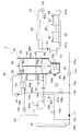
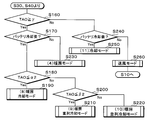
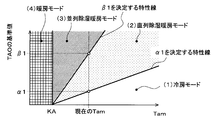
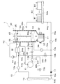
- 1 is an overall configuration diagram of a vehicle air conditioner according to a first embodiment. It is a block diagram which shows the electric control part of the vehicle air conditioner of 1st Embodiment. It is a flowchart which shows a part of control processing of the air conditioning control program of the first embodiment. It is a flowchart which shows another part of control processing of the air-conditioning control program of 1st Embodiment. It is a control characteristic figure for switching the operation mode of the air-conditioning control program of a 1st embodiment. It is another control characteristic figure for switching the operation mode of the air-conditioning control program of 1st Embodiment. It is another control characteristic figure for switching the operation mode of the air-conditioning control program of 1st Embodiment.
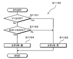
- FIG. 4 is a control characteristic diagram for determining an opening degree pattern of a heating expansion valve and a cooling expansion valve in a heating series cooling mode according to the first embodiment. It is a flowchart which shows the control processing of the heating parallel cooling mode of 1st Embodiment. It is a flowchart which shows the control processing for determining the opening degree pattern variation of the heating expansion valve and the cooling expansion valve in the heating parallel cooling mode of the first embodiment.
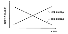
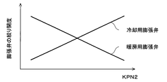
- FIG. 4 is a control characteristic diagram for determining an opening pattern of a heating expansion valve and a cooling expansion valve in a heating parallel cooling mode according to the first embodiment.
- the refrigeration cycle device 10 is applied to a vehicle air conditioner 1 mounted on an electric vehicle that obtains a driving force for traveling from an electric motor.
- the vehicle air conditioner 1 has a function of adjusting the temperature of the battery 80 as well as performing air conditioning of the vehicle interior, which is a space to be air-conditioned. For this reason, the vehicle air conditioner 1 can also be called an air conditioner with a battery temperature adjusting function.
- the battery 80 is a secondary battery that stores electric power supplied to in-vehicle devices such as an electric motor.
- the battery 80 of the present embodiment is a lithium ion battery.
- the battery 80 is a so-called assembled battery formed by stacking a plurality of battery cells 81 and electrically connecting these battery cells 81 in series or in parallel.
- the battery 80 can be cooled by the cold generated by the refrigeration cycle device 10. Therefore, the cooling object (in other words, the heat absorbing object) different from the blown air in the refrigeration cycle device 10 of the present embodiment is the battery 80.
- the vehicle air conditioner 1 includes a refrigeration cycle device 10, an indoor air conditioning unit 30, a high-temperature heat medium circuit 40, a low-temperature heat medium circuit 50, and the like, as shown in the overall configuration diagram of FIG.
- the refrigeration cycle apparatus 10 cools the air blown into the vehicle interior and heats the high-temperature side heat medium circulating in the high-temperature side heat medium circuit 40 in order to perform air conditioning in the vehicle interior. Further, the refrigeration cycle apparatus 10 cools the low-temperature side heat medium circulating in the low-temperature side heat medium circuit 50 in order to cool the battery 80.
- the refrigeration cycle device 10 is configured to be able to switch refrigerant circuits for various operation modes in order to perform air conditioning in the passenger compartment. For example, it is configured such that a refrigerant circuit in a cooling mode, a refrigerant circuit in a dehumidifying and heating mode, a refrigerant circuit in a heating mode, and the like can be switched. Further, the refrigeration cycle apparatus 10 can switch between an operation mode for cooling the battery 80 and an operation mode for not cooling the battery 80 in each operation mode for air conditioning.
- an HFO-based refrigerant (specifically, R1234yf) is employed as a refrigerant, and the pressure of the discharged refrigerant discharged from the compressor 11 does not exceed the critical pressure of the refrigerant. Constructs a subcritical refrigeration cycle. Further, a refrigerant oil for lubricating the compressor 11 is mixed in the refrigerant. Part of the refrigerating machine oil circulates through the cycle together with the refrigerant.
- the compressor 11 sucks, compresses, and discharges the refrigerant in the refrigeration cycle device 10.
- the compressor 11 is disposed in front of a vehicle compartment and is disposed in a driving device compartment in which an electric motor and the like are accommodated.
- the compressor 11 is an electric compressor in which a fixed displacement compression mechanism having a fixed discharge capacity is rotationally driven by an electric motor.
- the rotation speed (that is, the refrigerant discharge capacity) of the compressor 11 is controlled by a control signal output from a control device 60 described later.
- the inlet of the refrigerant passage of the water-refrigerant heat exchanger 12 is connected to the outlet of the compressor 11.
- the water-refrigerant heat exchanger 12 has a refrigerant passage through which the high-pressure refrigerant discharged from the compressor 11 flows, and a water passage through which the high-temperature side heat medium circulating through the high-temperature side heat medium circuit 40 flows.
- the water-refrigerant heat exchanger 12 is a heating heat exchanger that exchanges heat between the high-pressure refrigerant flowing through the refrigerant passage and the high-temperature heat medium flowing through the water passage to heat the high-temperature heat medium. is there.
- the water-refrigerant heat exchanger 12 is a radiator that radiates heat of the refrigerant discharged from the compressor 11 to the high-temperature side heat medium.
- the outlet of the coolant passage of the water-refrigerant heat exchanger 12 is connected to the inlet of a first three-way joint 13a having three inflow ports that communicate with each other.
- a three-way joint one formed by joining a plurality of pipes or one formed by providing a plurality of refrigerant passages in a metal block or a resin block can be employed.
- the refrigeration cycle device 10 includes second to sixth three-way joints 13b to 13f as described later.
- the basic configuration of the second to sixth three-way joints 13b to 13f is the same as that of the first three-way joint 13a.
- the inlet of the heating expansion valve 14a is connected to one outlet of the first three-way joint 13a.
- the other outlet of the first three-way joint 13a is connected to one inlet of the second three-way joint 13b via a bypass passage 22a.
- An on-off valve 15a for dehumidification is arranged in the bypass passage 22a.
- the dehumidifying on-off valve 15a is an electromagnetic valve that opens and closes a refrigerant passage connecting the other outflow side of the first three-way joint 13a and one inflow side of the second three-way joint 13b.
- the dehumidifying on-off valve 15a is a bypass opening and closing unit that opens and closes the bypass passage 22a.
- the refrigeration cycle device 10 includes a heating on-off valve 15b as described later.
- the basic configuration of the heating on-off valve 15b is the same as that of the dehumidifying on-off valve 15a.
- the on-off valve 15a for dehumidification and the on-off valve 15b for heating can switch the refrigerant circuit in each operation mode by opening and closing the refrigerant passage. Therefore, the on-off valve 15a for dehumidification and the on-off valve 15b for heating are refrigerant circuit switching devices for switching the refrigerant circuit of the cycle. The operations of the dehumidifying on-off valve 15a and the heating on-off valve 15b are controlled by a control voltage output from the control device 60.
- the heating expansion valve 14a depressurizes the high-pressure refrigerant flowing out of the refrigerant passage of the water-refrigerant heat exchanger 12 at least in the operation mode of heating the vehicle interior, and also causes the flow rate (mass flow rate) of the refrigerant to flow downstream. This is a heating decompression unit that adjusts the pressure.
- the heating expansion valve 14a is an electric variable throttle mechanism that includes a valve body configured to change the throttle opening and an electric actuator that changes the opening of the valve body.
- the refrigeration cycle apparatus 10 includes a cooling expansion valve 14b and a cooling expansion valve 14c, as described later.
- the basic configuration of the cooling expansion valve 14b and the cooling expansion valve 14c is the same as that of the heating expansion valve 14a.
- the heating expansion valve 14a, the cooling expansion valve 14b, and the cooling expansion valve 14c have a fully open function and a fully closed function.
- the full-opening function is a function of simply making the refrigerant passage without exerting the flow rate adjusting function and the refrigerant depressurizing function by fully opening the valve opening.
- the fully closed function is a function of closing the refrigerant passage by fully closing the valve opening.
- the heating expansion valve 14a, the cooling expansion valve 14b, and the cooling expansion valve 14c can switch the refrigerant circuit in each operation mode by the fully open function and the fully closed function.
- the heating expansion valve 14a, the cooling expansion valve 14b, and the cooling expansion valve 14c of the present embodiment also have a function as a refrigerant circuit switching device.
- the operations of the heating expansion valve 14a, the cooling expansion valve 14b, and the cooling expansion valve 14c are controlled by a control signal (control pulse) output from the control device 60.
- the refrigerant inlet side of the outdoor heat exchanger 16 is connected to the outlet of the heating expansion valve 14a.
- the outdoor heat exchanger 16 is a heat exchanger that exchanges heat between the refrigerant flowing out of the heating expansion valve 14a and the outside air blown by a cooling fan (not shown).
- the outdoor heat exchanger 16 functions as a radiator for releasing the refrigerant discharged from the compressor 11 or an air conditioning heat exchanger for absorbing heat from air and evaporating the refrigerant, depending on the operation mode.
- the outdoor heat exchanger 16 is arranged on the front side in the drive device room. Therefore, when the vehicle is traveling, the traveling wind can be applied to the outdoor heat exchanger 16.
- the first refrigerant passage 16a is a refrigerant passage for guiding the refrigerant flowing out of the water-refrigerant heat exchanger 12 to the inlet side of the outdoor heat exchanger 16, and corresponds to an air conditioning passage.
- the heating expansion valve 14a is an air-conditioning decompression unit that adjusts the opening area of the first refrigerant passage 16a to adjust the decompression amount of the refrigerant flowing into the outdoor heat exchanger 16.
- the heating expansion valve 14a corresponds to a first throttle section.
- the refrigerant outlet of the outdoor heat exchanger 16 is connected to the inlet side of the third three-way joint 13c.
- One outlet of the fourth three-way joint 13d is connected to one outlet of the third three-way joint 13c via a heating passage 22b.
- the heating passage 22b is a second refrigerant passage for guiding the refrigerant flowing out of the outdoor heat exchanger 16 to the suction side of the compressor 11.
- a heating on-off valve 15b for opening and closing the refrigerant passage is arranged in the heating passage 22b.
- the heating on-off valve 15b is a second refrigerant passage opening / closing unit that opens and closes the second refrigerant passage.
- the other inlet of the second three-way joint 13b is connected to the other outlet of the third three-way joint 13c.
- a check valve 17 is arranged in the refrigerant passage connecting the other outlet side of the third three-way joint 13c and the other inlet side of the second three-way joint 13b. The check valve 17 allows the refrigerant to flow from the third three-way joint 13c to the second three-way joint 13b, and prohibits the refrigerant from flowing from the second three-way joint 13b to the third three-way joint 13c.
- the outlet of the fifth three-way joint 13e is connected to the outlet of the second three-way joint 13b.
- the inlet side of the cooling expansion valve 14b is connected to one outlet of the fifth three-way joint 13e.
- the inlet side of the cooling expansion valve 14c is connected to the other outlet of the fifth three-way joint 13e.
- the cooling expansion valve 14b is a heating decompression unit that depressurizes the refrigerant that has flowed out of the outdoor heat exchanger 16 and adjusts the flow rate of the refrigerant that flows downstream, at least in an operation mode in which cooling is performed in the vehicle interior.
- the refrigerant inlet side of the indoor evaporator 18 is connected to the outlet of the cooling expansion valve 14b.
- the indoor evaporator 18 is arranged in an air-conditioning case 31 of an indoor air-conditioning unit 30 described later.
- the indoor evaporator 18 blows air by exchanging heat between the low-pressure refrigerant depressurized by the cooling expansion valve 14b and the blast air blown from the blower 32 to evaporate the low-pressure refrigerant and exerting an endothermic effect on the low-pressure refrigerant.
- This is a cooling heat exchanger that cools air.
- the indoor evaporator 18 is an air-conditioning heat exchanger that absorbs heat from air to evaporate the refrigerant.
- One inlet side of the sixth three-way joint 13f is connected to the refrigerant outlet of the indoor evaporator 18.
- the cooling expansion valve 14c is a cooling pressure reducing unit that reduces the pressure of the refrigerant flowing out of the outdoor heat exchanger 16 and adjusts the flow rate of the refrigerant flowing downstream at least in the operation mode in which the battery 80 is cooled.
- the outlet side of the cooling expansion valve 14c is connected to the inlet side of the refrigerant passage of the chiller 19.
- the chiller 19 has a refrigerant passage through which the low-pressure refrigerant depressurized by the cooling expansion valve 14c flows, and a water passage through which the low-temperature heat medium circulating through the low-temperature heat medium circuit 50 flows.
- the chiller 19 is an evaporator that exchanges heat between the low-pressure refrigerant flowing through the refrigerant passage and the low-temperature side heat medium flowing through the water passage, evaporates the low-pressure refrigerant, and exerts an endothermic effect.
- the chiller 19 is a cooling heat exchanger that absorbs heat from the low-temperature side heat medium and evaporates the refrigerant.
- the chiller 19 is arranged in parallel with at least one of the outdoor heat exchanger 16 and the indoor evaporator 18 in the flow of the refrigerant radiated by the water-refrigerant heat exchanger 12.
- the other inlet side of the sixth three-way joint 13f is connected to the outlet of the refrigerant passage of the chiller 19.
- the inlet of the evaporation pressure regulating valve 20 is connected to the outlet of the sixth three-way joint 13f.
- the evaporation pressure regulating valve 20 maintains the refrigerant evaporation pressure in the indoor evaporator 18 at or above a predetermined reference pressure in order to suppress frost formation on the indoor evaporator 18.
- the evaporating pressure adjusting valve 20 is configured by a mechanical variable throttle mechanism that increases the valve opening as the pressure of the refrigerant on the outlet side of the indoor evaporator 18 increases.
- the evaporation pressure regulating valve 20 maintains the refrigerant evaporation temperature in the indoor evaporator 18 at a frost formation suppression temperature (1 ° C. in the present embodiment) capable of suppressing frost formation on the indoor evaporator 18. . Furthermore, the evaporating pressure regulating valve 20 of the present embodiment is disposed downstream of the sixth three-way joint 13f, which is the junction. For this reason, the evaporation pressure regulating valve 20 also maintains the refrigerant evaporation temperature in the chiller 19 at a temperature equal to or higher than the frost formation suppression temperature.
- the other inlet side of the fourth three-way joint 13d is connected to the outlet of the evaporation pressure regulating valve 20.
- the inlet of the accumulator 21 is connected to the outlet of the fourth three-way joint 13d.
- the accumulator 21 is a gas-liquid separator that separates the gas-liquid of the refrigerant flowing into the inside and stores the surplus liquid-phase refrigerant in the cycle.
- the suction port side of the compressor 11 is connected to the gas-phase refrigerant outlet of the accumulator 21.
- the third refrigerant passage 18a is a refrigerant passage for guiding the refrigerant flowing out of the outdoor heat exchanger 16 to the suction side of the compressor 11 via the evaporator 18, and corresponds to an air conditioning passage.
- the cooling expansion valve 14b is an air conditioning decompression unit that adjusts the opening area of the third refrigerant passage 18a to adjust the pressure reduction amount of the refrigerant flowing into the evaporator 18.
- the cooling expansion valve 14b corresponds to a second throttle unit.
- the cooling passage 19a transfers the refrigerant flowing between the outdoor heat exchanger 16 and the cooling expansion valve 14b to the third refrigerant passage 18a between the indoor evaporator 18 and the suction side of the compressor 11 via the chiller 19. It is a refrigerant passage for guiding.
- the cooling expansion valve 14c is a cooling decompression unit that adjusts the opening area of the cooling passage 19a to adjust the amount of decompression of the refrigerant flowing into the chiller 19.
- the fifth three-way joint 13e of the present embodiment functions as a branch part that branches the flow of the refrigerant flowing out of the outdoor heat exchanger 16.
- the sixth three-way joint 13 f is a junction where the flow of the refrigerant flowing out of the indoor evaporator 18 and the flow of the refrigerant flowing out of the chiller 19 are merged and flown out to the suction side of the compressor 11.
- the indoor evaporator 18 and the chiller 19 are connected in parallel with each other with respect to the refrigerant flow. Further, the bypass passage 22a guides the refrigerant flowing out of the refrigerant passage of the water-refrigerant heat exchanger 12 to an upstream side of the branch portion. The heating passage 22 b guides the refrigerant flowing out of the outdoor heat exchanger 16 to the suction port side of the compressor 11.
- the high-temperature side heat medium circuit 40 is a heat medium circulation circuit that circulates the high-temperature side heat medium.
- the high-temperature side heat medium a solution containing ethylene glycol, dimethylpolysiloxane, a nanofluid, or the like, an antifreeze, or the like can be used.
- the high-temperature-side heat medium circuit 40 includes a water passage of the water-refrigerant heat exchanger 12, a high-temperature-side heat medium pump 41, a heater core 42, and the like.
- the high-temperature heat medium pump 41 is a water pump that pumps the high-temperature heat medium to the inlet side of the water passage of the water-refrigerant heat exchanger 12.
- the high-temperature-side heat medium pump 41 is an electric pump whose rotation speed (ie, pumping capacity) is controlled by a control voltage output from the control device 60.
- the outlet of the water passage of the water-refrigerant heat exchanger 12 is connected to the heat medium inlet side of the heater core 42.
- the heater core 42 is a heat exchanger that heats the blown air by exchanging heat between the high-temperature side heat medium heated by the water-refrigerant heat exchanger 12 and the blown air that has passed through the indoor evaporator 18.
- the heater core 42 is arranged inside the air conditioning case 31 of the indoor air conditioning unit 30.
- the heat medium outlet of the heater core 42 is connected to the suction port side of the high-temperature side heat medium pump 41.
- the high-temperature side heat medium pump 41 adjusts the flow rate of the high-temperature side heat medium flowing into the heater core 42, so that the heat radiation amount of the high-temperature side heat medium to the blow air in the heater core 42 is reduced. Can be adjusted. That is, in the high-temperature-side heat medium circuit 40, the high-temperature-side heat medium pump 41 adjusts the flow rate of the high-temperature-side heat medium flowing into the heater core 42, so that the heating amount of the blown air in the heater core 42 can be adjusted.
- each component of the water-refrigerant heat exchanger 12 and the high-temperature side heat medium circuit 40 constitutes a heating unit that heats the blown air using the refrigerant discharged from the compressor 11 as a heat source. I have.
- the low-temperature-side heat medium circuit 50 is a heat medium circulation circuit that circulates the low-temperature-side heat medium.
- the same fluid as the high-temperature side heat medium can be used as the low-temperature side heat medium.
- a water passage of the chiller 19 a low-temperature side heat medium pump 51, a cooling heat exchange section 52, a three-way valve 53, a low-temperature side radiator 54, and the like are arranged.
- the low-temperature heat medium pump 51 is a water pump that pumps the low-temperature heat medium to the inlet side of the water passage of the chiller 19.
- the basic configuration of the low-temperature-side heat medium pump 51 is the same as that of the high-temperature-side heat medium pump 41.
- the inlet side of the cooling heat exchange unit 52 is connected to the outlet of the water passage of the chiller 19.
- the cooling heat exchanging section 52 has a plurality of metal heat medium passages arranged to be in contact with the plurality of battery cells 81 forming the battery 80.
- the heat exchange unit cools the battery 80 by exchanging heat between the battery cell 81 and the low-temperature side heat medium flowing through the heat medium flow path.
- Such a cooling heat exchange section 52 may be formed by disposing a heat medium flow path between the battery cells 81 arranged in a stack. Further, cooling heat exchanging section 52 may be formed integrally with battery 80.
- the battery case may be formed integrally with the battery 80 by providing a heat medium flow path in a dedicated case for accommodating the stacked battery cells 81.
- the outlet of the cooling heat exchange unit 52 is connected to the inflow side of the three-way valve 53.
- the three-way valve 53 is an electric three-way flow control valve having one inflow port and two outflow ports, and capable of continuously adjusting the passage area ratio of the two outflow ports. The operation of the three-way valve 53 is controlled by a control signal output from the control device 60.
- the heat medium inlet side of the low-temperature radiator 54 is connected to one outlet of the three-way valve 53.
- the other outlet of the three-way valve 53 is connected to the suction side of the low-temperature side heat transfer medium pump 51 via a radiator bypass passage 53a.
- the radiator bypass flow path 53 a is a heat medium flow path in which the low-temperature side heat medium flowing out of the cooling heat exchange unit 52 flows by bypassing the low-temperature side radiator 54.
- the three-way valve 53 continuously adjusts the flow rate of the low-temperature side heat medium flowing into the low-temperature side radiator 54 among the low-temperature side heat medium flowing out of the cooling heat exchange section 52 in the low-temperature side heat medium circuit 50. .
- the low-temperature radiator 54 exchanges heat between the low-temperature heat medium flowing out of the cooling heat exchange unit 52 and the outside air blown by an outside air fan (not shown), and radiates heat of the low-temperature heat medium to the outside air. It is a vessel.
- the low-temperature radiator 54 is disposed on the front side in the drive device chamber. Therefore, when the vehicle is traveling, the traveling wind can be applied to the low-temperature radiator 54. Therefore, the low temperature radiator 54 may be formed integrally with the outdoor heat exchanger 16 and the like.
- the heat medium outlet of the low-temperature radiator 54 is connected to the suction port side of the low-temperature heat medium pump 51. Therefore, in the low-temperature heat medium circuit 50, the low-temperature heat medium pump 51
- the cooling unit that cools the battery 80 by evaporating the refrigerant flowing out of the cooling expansion valve 14c is configured by the respective components of the chiller 19 and the low-temperature side heat medium circuit 50.
- the indoor air-conditioning unit 30 is for blowing out the blast air whose temperature has been adjusted by the refrigeration cycle device 10 into the vehicle interior.
- the indoor air-conditioning unit 30 is arranged inside the instrument panel (instrument panel) at the forefront of the passenger compartment.
- the indoor air-conditioning unit 30 accommodates a blower 32, an indoor evaporator 18, a heater core 42, and the like in an air passage formed in an air-conditioning case 31 forming an outer shell.
- the air-conditioning case 31 forms an air passage for blast air blown into the vehicle interior.
- the air-conditioning case 31 has a certain degree of elasticity and is formed of a resin (for example, polypropylene) excellent in strength.
- An inside / outside air switching device 33 is disposed on the most upstream side of the airflow of the air conditioning case 31.
- the inside / outside air switching device 33 switches between the inside air (vehicle interior air) and the outside air (vehicle outside air) into the air conditioning case 31.
- the inside / outside air switching device 33 continuously adjusts the opening area of the inside air introduction port for introducing the inside air into the air conditioning case 31 and the outside air introduction port for introducing the outside air by the inside / outside air switching door, and the inside air introduction air volume and the outside air. Is to change the ratio of the introduced air flow to the introduced air flow.
- the inside / outside air switching door is driven by an electric actuator for the inside / outside air switching door. The operation of the electric actuator is controlled by a control signal output from the control device 60.
- a blower 32 is disposed downstream of the inside / outside air switching device 33 in the flow of the blown air.
- the blower 32 blows the air taken in through the inside / outside air switching device 33 toward the vehicle interior.
- the blower 32 is an electric blower that drives a centrifugal multi-blade fan with an electric motor.
- the rotation speed (that is, the blowing capacity) of the blower 32 is controlled by the control voltage output from the control device 60.
- the indoor evaporator 18 and the heater core 42 are arranged in this order with respect to the blown air flow. That is, the indoor evaporator 18 is arranged on the upstream side of the flow of the blown air with respect to the heater core 42.
- a cool air bypass passage 35 is provided in the air-conditioning case 31 to allow the air blown after passing through the indoor evaporator 18 to bypass the heater core 42.
- An air mix door 34 is arranged on the downstream side of the air flow of the indoor evaporator 18 in the air conditioning case 31 and on the upstream side of the air flow of the heater core 42.
- the air mix door 34 adjusts a flow rate ratio of a flow rate of the blown air passing through the heater core 42 and a flow rate of the blown air passing through the cool air bypass passage 35 among the blown air after passing through the indoor evaporator 18. Department.
- the air mix door 34 is driven by an electric actuator for the air mix door. The operation of the electric actuator is controlled by a control signal output from the control device 60.
- the mixing space is disposed downstream of the air flow of the heater core 42 and the cool air bypass passage 35 in the air conditioning case 31.
- the mixing space is a space that mixes the blast air heated by the heater core 42 with the blast air that has not passed through the cool air bypass passage 35 and is not heated.
- an opening hole for blowing out the blast air mixed in the mixing space (that is, the conditioned air) into the vehicle interior, which is the space to be air-conditioned, is arranged downstream of the airflow of the air-conditioning case 31.
- the face opening hole is an opening hole for blowing out conditioned air toward the upper body of the occupant in the passenger compartment.
- the foot opening hole is an opening hole for blowing out conditioned air toward the feet of the occupant.
- the defroster opening hole is an opening hole for blowing out conditioned air toward the inside surface of the vehicle front window glass.
- the face opening, the foot opening, and the defroster opening are respectively formed by a face opening, a foot opening, and a defroster opening provided in the vehicle cabin through ducts forming air passages. )It is connected to the.
- the temperature of the conditioned air mixed in the mixing space is adjusted by adjusting the air flow ratio of the air flow passing through the heater core 42 and the air flow passing through the cool air bypass passage 35 by the air mixing door 34. Then, the temperature of the blown air (conditioned air) blown out from each outlet into the vehicle interior is adjusted.
- Face doors, foot doors, and defroster doors are disposed on the upstream side of the airflow from the face opening, the foot opening, and the defroster opening.
- the face door adjusts the opening area of the face opening hole.
- the foot door adjusts the opening area of the foot opening hole.
- the defroster door is for adjusting the opening area of the froster opening hole.
- These face doors, foot doors and defroster doors constitute an outlet mode switching device for switching the outlet mode.
- These doors are connected to an electric actuator for driving the outlet mode door via a link mechanism or the like, and are rotated in conjunction therewith.
- the operation of the electric actuator is also controlled by a control signal output from the control device 60.
- Specific examples of the outlet mode switched by the outlet mode switching device include a face mode, a bi-level mode, and a foot mode.
- the face mode is an outlet mode in which the face outlet is fully opened and air is blown from the face outlet toward the upper body of the occupant in the vehicle.
- the bi-level mode is an outlet mode in which both the face outlet and the foot outlet are opened to blow air toward the upper body and feet of the occupant in the vehicle.
- the foot mode is an outlet mode in which the foot outlet is fully opened and the defroster outlet is opened by a small opening, and air is mainly blown out from the foot outlet.
- the defroster mode is an outlet mode in which the defroster outlet is fully opened and air is blown from the defroster outlet to the inner surface of the windshield.
- the control device 60 is a control unit including a well-known microcomputer including a CPU, a ROM, a RAM, and the like, and peripheral circuits thereof. Then, various calculations and processes are performed based on the air-conditioning control program stored in the ROM, and various control target devices 11, 14a to 14c, 15a, 15b, 32, 41, 51, 53 connected to the output side. And the like.
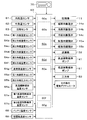
- Temperature sensor 64g On the input side of the control device 60, as shown in the block diagram of FIG. Temperature sensor 64g, first refrigerant pressure sensor 65a, second refrigerant pressure sensor 65b, high-temperature heat medium temperature sensor 66a, first low-temperature heat medium temperature sensor 67a, second low-temperature heat medium temperature sensor 67b, battery temperature sensor 68, an air-conditioning air temperature sensor 69 and the like are connected.
- the control unit 60 receives detection signals from these sensor groups.
- the internal air temperature sensor 61 is an internal air temperature detecting unit that detects the vehicle interior temperature (internal air temperature) Tr.
- the outside air temperature sensor 62 is an outside air temperature detection unit that detects a vehicle outside temperature (outside air temperature) Tam.
- the solar radiation sensor 63 is a solar radiation amount detecting unit that detects a solar radiation amount Ts irradiated to the vehicle interior.
- the first refrigerant temperature sensor 64a is a discharge refrigerant temperature detection unit that detects the temperature T1 of the refrigerant discharged from the compressor 11.
- the second refrigerant temperature sensor 64b is a second refrigerant temperature detector that detects the temperature T2 of the refrigerant flowing out of the refrigerant passage of the water-refrigerant heat exchanger 12.
- the third refrigerant temperature sensor 64c is a third refrigerant temperature detecting unit that detects the temperature T3 of the refrigerant flowing out of the outdoor heat exchanger 16.
- the fourth refrigerant temperature sensor 64d is a fourth refrigerant temperature detector that detects the temperature T4 of the refrigerant flowing out of the indoor evaporator 18.
- the fifth refrigerant temperature sensor 64e is a fifth refrigerant temperature detector that detects the temperature T5 of the refrigerant flowing out of the refrigerant passage of the chiller 19.
- the sixth refrigerant temperature sensor 64f is a suction refrigerant temperature detection unit that detects the temperature T6 of the suction refrigerant drawn into the compressor 11, and constitutes the suction refrigerant detection unit.
- the evaporator temperature sensor 64g is an evaporator temperature detector that detects the refrigerant evaporation temperature (evaporator temperature) Tefin in the indoor evaporator 18. Specifically, the evaporator temperature sensor 64g of this embodiment detects the heat exchange fin temperature of the indoor evaporator 18.
- the first refrigerant pressure sensor 65a is a first refrigerant pressure detector that detects the pressure P1 of the refrigerant flowing out of the refrigerant passage of the water-refrigerant heat exchanger 12.
- the second refrigerant pressure sensor 65b is a second refrigerant pressure detector that detects the pressure P2 of the refrigerant flowing out of the refrigerant passage of the chiller 19.
- the high-temperature heat medium temperature sensor 66a is a high-temperature heat medium temperature detection unit that detects the high-temperature heat medium temperature TWH, which is the temperature of the high-temperature heat medium flowing out of the water passage of the water-refrigerant heat exchanger 12.
- the first low-temperature heat medium temperature sensor 67a is a first low-temperature heat medium temperature detection unit that detects the first low-temperature heat medium temperature TWL1, which is the temperature of the low-temperature heat medium flowing out of the water passage of the chiller 19.
- the second low-temperature-side heat medium temperature sensor 67b is a second low-temperature-side heat medium temperature detection unit that detects the second low-temperature-side heat medium temperature TWL2 that is the temperature of the low-temperature side heat medium flowing out of the cooling heat exchange unit 52. .
- the battery temperature sensor 68 is a battery temperature detector that detects the battery temperature TB (that is, the temperature of the battery 80).
- the battery temperature sensor 68 of the present embodiment has a plurality of temperature sensors and detects temperatures at a plurality of locations of the battery 80. For this reason, the control device 60 can also detect a temperature difference between the components of the battery 80. Further, as the battery temperature TB, an average value of detection values of a plurality of temperature sensors is employed.
- the air-conditioning air temperature sensor 69 is an air-conditioning air temperature detecting unit that detects the temperature of the air blown from the mixing space into the vehicle compartment TAV.
- an operation panel 70 disposed near the instrument panel in the front of the vehicle compartment is connected to the input side of the control device 60, and operation from various operation switches provided on the operation panel 70 is performed. A signal is input.
- Specific examples of various operation switches provided on the operation panel 70 include an auto switch, an air conditioner switch, an air volume setting switch, a temperature setting switch, a blowing mode switching switch, and the like.
- the auto switch is an operation unit for setting or canceling the automatic control operation of the vehicle air conditioner.
- the air conditioner switch is an operation unit that requests that the blown air be cooled by the indoor evaporator 18.
- the air volume setting switch is an operation unit for manually setting the air volume of the blower 32.
- the temperature setting switch is an operation unit that sets a target temperature Tset in the vehicle compartment.
- the blowout mode changeover switch is an operation unit for manually setting the blowout mode.
- the control device 60 of the present embodiment has an integrated control unit for controlling various control target devices connected to the output side.
- the configuration (hardware and software) of the control device 60 that controls the operation of each device to be controlled constitutes a control unit that controls the operation of each device to be controlled.
- the configuration for controlling the refrigerant discharge capacity of the compressor 11 constitutes the compressor control unit 60a.
- the configuration for controlling the operations of the heating expansion valve 14a, the cooling expansion valve 14b, and the cooling expansion valve 14c constitutes an expansion valve control unit 60b.
- the configuration for controlling the operations of the dehumidifying on-off valve 15a and the heating on-off valve 15b constitutes a refrigerant circuit switching control unit 60c.
- the configuration for controlling the pumping capacity of the high-temperature side heat medium pump of the high-temperature side heat medium pump 41 constitutes the high-temperature side heat medium pump control unit 60d.
- the configuration for controlling the low-temperature-side heat medium pumping capability of the low-temperature-side heat medium pump 51 constitutes a low-temperature-side heat medium pump control unit 60e.
- the control device 60 has a refrigerant flow rate calculation unit 60f that calculates the flow rate V1 of the refrigerant flowing into the chiller 19.
- the refrigerant flow rate detecting unit 60f firstly detects the flow rate V2 of the refrigerant discharged from the compressor 11 based on the temperature T6 of the refrigerant suctioned by the compressor 11 detected by the sixth refrigerant temperature sensor 64f and the rotation speed of the compressor 11. Is calculated.
- the refrigerant flow rate detection unit 60f determines the opening area of the cooling passage 19a and the opening area of the refrigerant passage of the first refrigerant passage 16a and the third refrigerant passage 18a in which the refrigerant flow is parallel to the cooling passage 19a. Is calculated.
- the refrigerant flow detecting unit 60f calculates the flow V1 of the refrigerant flowing into the chiller 19 based on the flow V2 of the refrigerant discharged from the compressor 11 and the opening area ratio. Therefore, the refrigerant flow rate calculating section 60f of the present embodiment constitutes a refrigerant flow rate detecting section.
- the control device 60 includes a superheat degree calculating unit 60g that calculates the superheat degree SHC of the refrigerant flowing out of the refrigerant passage of the chiller 19.
- the superheat degree calculation unit 60g calculates the superheat degree SHC of the refrigerant flowing out of the refrigerant passage of the chiller 19 based on the temperature T5 detected by the fifth refrigerant temperature sensor 64e and the pressure P2 detected by the second refrigerant pressure sensor 65b. calculate. Therefore, the superheat degree calculator 60g of the present embodiment constitutes a superheat degree detector.
- the vehicle air conditioner 1 of the present embodiment has a function of adjusting the temperature of the battery 80 as well as performing air conditioning of the vehicle interior. For this reason, in the refrigeration cycle apparatus 10, it is possible to perform operation in the following 11 operation modes by switching the refrigerant circuit.
- Cooling mode is an operation mode in which the inside of the vehicle compartment is cooled by cooling the blown air and blowing it out into the vehicle compartment without cooling the battery 80.
- In-series dehumidification heating mode is an operation in which the cooled and dehumidified blast air is reheated and blown out into the vehicle compartment without cooling the battery 80 to perform dehumidification and heating in the vehicle compartment. Mode.
- Parallel dehumidifying and heating mode In the parallel dehumidifying and heating mode, the cooled and dehumidified blast air is reheated with a higher heating capacity than the serial dehumidifying and heating mode and is blown into the vehicle interior without cooling the battery 80. This is an operation mode for performing dehumidification and heating of the vehicle interior.
- the heating mode is an operation mode in which the inside of the vehicle compartment is heated by heating the blown air and blowing it out into the vehicle compartment without cooling the battery 80.
- Cooling cooling mode is an operation mode in which the battery 80 is cooled, and the inside of the vehicle compartment is cooled by cooling the blown air and blowing it out into the vehicle compartment.
- Series dehumidification heating / cooling mode performs cooling of the battery 80, and also performs dehumidification and heating of the vehicle interior by reheating the cooled and dehumidified blast air and blowing it out into the vehicle interior. Operation mode.
- Parallel dehumidification heating / cooling mode cools the battery 80 and reheats the cooled and dehumidified blast air with a higher heating capacity than the serial dehumidification heating / cooling mode to achieve cabin interior. This is an operation mode in which dehumidification and heating of the vehicle interior is performed by blowing air to the vehicle interior.
- Heating / cooling mode is an operation mode in which the battery 80 is cooled, and the inside of the vehicle is heated by heating the blast air and blowing it out into the vehicle interior.
- Heating series cooling mode In the heating series cooling mode, the operation of cooling the battery 80 and heating the inside of the vehicle by heating the blast air with a higher heating capacity than the heating and cooling mode and blowing the air into the vehicle interior. Mode.
- Heating parallel cooling mode In the heating parallel cooling mode, the battery 80 is cooled, and the blast air is heated with a higher heating capacity than the heating serial cooling mode and is blown into the vehicle cabin, thereby heating the vehicle cabin. Operation mode.
- Cooling mode This is an operation mode in which the battery 80 is cooled without performing air conditioning in the passenger compartment.
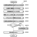
- the air-conditioning control program is executed when an automatic switch of the operation panel 70 is turned on (ON) by an occupant's operation and automatic control of the vehicle interior is set.
- the air conditioning control program will be described with reference to FIGS.
- Each control step shown in the flowchart of FIG. 3 and the like is a function realizing unit of the control device 60.
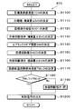
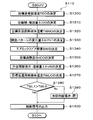
- step S10 of FIG. 3 the detection signal of the above-described sensor group and the operation signal of the operation panel 70 are read.
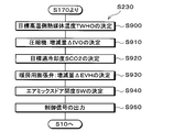
- a target outlet temperature TAO which is a target temperature of the air blown into the vehicle interior, is determined based on the detection signal and the operation signal read in step S10. Therefore, step S20 is a target outlet temperature determination unit.
- TAO Kset ⁇ Tset ⁇ Kr ⁇ Tr ⁇ Kam ⁇ Tam ⁇ Ks ⁇ Ts + C (F1)
- Tset is a vehicle interior set temperature set by the temperature setting switch. Tr is a vehicle interior temperature detected by the inside air sensor. Tam is the vehicle outside temperature detected by the outside air sensor. Ts is the amount of solar radiation detected by the solar radiation sensor. Kset, Kr, Kam, and Ks are control gains, and C is a correction constant.
- step S30 it is determined whether or not the air conditioner switch is ON (turned on).
- the fact that the air conditioner switch is turned on means that the occupant is requesting cooling or dehumidification in the vehicle interior.
- the fact that the air conditioner switch is ON means that it is required to cool the blown air in the indoor evaporator 18.
- step S30 If it is determined in step S30 that the air conditioner switch is ON, the process proceeds to step S40. If it is determined in step S30 that the air conditioner switch has not been turned on, the process proceeds to step S160.
- step S40 it is determined whether the outside temperature Tam is equal to or higher than a predetermined reference outside temperature KA (0 ° C. in the present embodiment).
- the reference outside air temperature KA is set so that cooling of the blown air by the indoor evaporator 18 is effective for cooling or dehumidifying the space to be air-conditioned.
- the evaporation pressure regulating valve 20 changes the refrigerant evaporation temperature in the indoor evaporator 18 into a frost formation suppression temperature (1 ° C. in the present embodiment). ) Or more. For this reason, in the indoor evaporator 18, the blown air cannot be cooled to a temperature lower than the frost formation suppression temperature.
- the reference outside air temperature KA is set to a value lower than the frost formation suppression temperature, and when the outside air temperature Tam is lower than the reference outside air temperature KA, the air blown by the indoor evaporator 18 is not cooled. .
- step S40 If it is determined in step S40 that the outside temperature Tam is equal to or higher than the reference outside temperature KA, the process proceeds to step S50. If it is determined in step S40 that the outside temperature Tam is not equal to or higher than the reference outside temperature KA, the process proceeds to step S160.
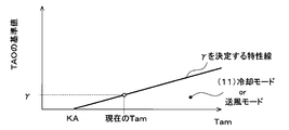
- step S50 it is determined whether the target outlet temperature TAO is equal to or lower than the cooling reference temperature ⁇ 1.
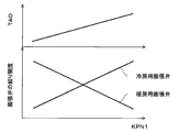
- the cooling reference temperature ⁇ 1 is determined based on the outside air temperature Tam with reference to a control map stored in the control device 60 in advance. In the present embodiment, as shown in FIG. 5, the cooling reference temperature ⁇ 1 is determined to be a low value as the outside temperature Tam decreases.
- step S50 If it is determined in step S50 that the target outlet temperature TAO is equal to or lower than the cooling reference temperature ⁇ 1, the process proceeds to step S60. If it is determined in step S50 that the target outlet temperature TAO is not lower than the cooling reference temperature ⁇ 1, the process proceeds to step S90.
- step S60 it is determined whether cooling of battery 80 is necessary. Specifically, in the present embodiment, when the battery temperature TB detected by the battery temperature sensor 68 is equal to or higher than a predetermined reference cooling temperature KTB (35 ° C. in the present embodiment), the cooling of the battery 80 is performed. Is determined to be necessary. When battery temperature TB is lower than reference cooling temperature KTB, it is determined that cooling of battery 80 is not necessary.
- a predetermined reference cooling temperature KTB 35 ° C. in the present embodiment
- step S60 If it is determined in step S60 that the cooling of the battery 80 is necessary, the process proceeds to step S70, and the cooling mode (5) is selected as the operation mode. If it is determined in step S60 that cooling of battery 80 is not necessary, the process proceeds to step S80, and (1) cooling mode is selected as the operation mode.
- step S90 it is determined whether the target outlet temperature TAO is equal to or lower than the dehumidifying reference temperature ⁇ 1.
- the dehumidifying reference temperature ⁇ 1 is determined based on the outside temperature Tam with reference to a control map stored in the control device 60 in advance.
- the dehumidification reference temperature ⁇ 1 is determined to be a low value as the outside air temperature Tam decreases. Further, the dehumidifying reference temperature ⁇ 1 is determined to be higher than the cooling reference temperature ⁇ 1.
- step S90 If it is determined in step S90 that the target outlet temperature TAO is equal to or lower than the dehumidifying reference temperature ⁇ 1, the process proceeds to step S100. If it is determined in step S90 that the target outlet temperature TAO is not lower than the dehumidifying reference temperature ⁇ 1, the process proceeds to step S130.
- step S100 similarly to step S60, it is determined whether cooling of battery 80 is necessary.
- step S100 If it is determined in step S100 that cooling of the battery 80 is necessary, the process proceeds to step S110, and (6) the in-line dehumidifying heating / cooling mode is selected as the operation mode of the refrigeration cycle apparatus 10. If it is determined in step S100 that cooling of battery 80 is not necessary, the process proceeds to step S120, and (2) in-line dehumidifying and heating mode is selected as the operation mode.
- step S130 similarly to step S60, it is determined whether cooling of battery 80 is necessary.
- step S130 If it is determined in step S130 that cooling of the battery 80 is necessary, the process proceeds to step S140, and (7) the parallel dehumidifying heating / cooling mode is selected as the operation mode of the refrigeration cycle device 10. If it is determined in step S100 that cooling of battery 80 is not necessary, the process proceeds to step S150, and (3) the parallel dehumidifying and heating mode is selected as the operation mode.
- step S160 it is determined that cooling the blown air by the indoor evaporator 18 is not effective.
- step S160 as shown in FIG. 4, it is determined whether or not the target outlet temperature TAO is equal to or higher than the heating reference temperature ⁇ .
- the heating reference temperature ⁇ is determined based on the outside air temperature Tam with reference to a control map stored in the control device 60 in advance. In the present embodiment, as shown in FIG. 6, the heating reference temperature ⁇ is determined to be a low value as the outside temperature Tam decreases. The heating reference temperature ⁇ is set such that heating of the blast air by the heater core 42 is effective for heating the space to be air-conditioned.
- step S160 If it is determined in step S160 that the target outlet temperature TAO is equal to or higher than the heating reference temperature ⁇ , it is necessary to heat the blown air by the heater core 42, and the process proceeds to step S170. If it is determined in step S160 that the target outlet temperature TAO is not equal to or higher than the heating reference temperature ⁇ , it is not necessary to heat the blown air by the heater core 42, and the process proceeds to step S240.
- step S170 similarly to step S60, it is determined whether cooling of battery 80 is necessary.
- step S170 If it is determined in step S170 that cooling of battery 80 is necessary, the process proceeds to step S180. If it is determined in step S170 that cooling of battery 80 is not necessary, the process proceeds to step S230, and (4) heating mode is selected as the operation mode.
- step S170 if it is determined in step S170 that cooling of battery 80 is necessary and the process proceeds to step S180, both heating of the vehicle interior and cooling of battery 80 need to be performed. Therefore, in the refrigeration cycle apparatus 10, the amount of heat released by the refrigerant to the high-temperature heat medium in the water-refrigerant heat exchanger 12 and the amount of heat absorbed by the refrigerant in the chiller 19 from the low-temperature heat medium are appropriately determined. Need to adjust.
- the operation mode is switched as shown in steps S180 to S220 in FIG. Specifically, the refrigeration cycle apparatus 10 of the present embodiment switches between three operation modes: (8) a heating / cooling mode, (9) a heating series cooling mode, and (10) a heating parallel cooling mode.
- step S180 it is determined whether or not the target outlet temperature TAO is equal to or lower than the first cooling reference temperature ⁇ 2.
- the first cooling reference temperature ⁇ 2 is determined based on the outside air temperature Tam with reference to a control map stored in the control device 60 in advance.
- the first cooling reference temperature ⁇ 2 is determined to be a low value as the outside temperature Tam decreases. Further, at the same outside temperature Tam, the first cooling reference temperature ⁇ 2 is determined to be higher than the cooling reference temperature ⁇ 1.
- step S180 If it is determined in step S180 that the target outlet temperature TAO is equal to or lower than the first cooling reference temperature ⁇ 2, the process proceeds to step S190, and (8) the heating / cooling mode is selected as the operation mode. If it is determined in step S180 that the target outlet temperature TAO is not lower than the first cooling reference temperature ⁇ 2, the process proceeds to step S200.
- step S200 it is determined whether or not target outlet temperature TAO is equal to or lower than second cooling reference temperature ⁇ 2.
- the second cooling reference temperature ⁇ 2 is determined based on the outside air temperature Tam with reference to a control map stored in the control device 60 in advance.
- the second cooling reference temperature ⁇ 2 is determined to be a low value as the outside air temperature Tam decreases. Further, the second cooling reference temperature ⁇ 2 is determined to be higher than the first cooling reference temperature ⁇ 2. At the same outside temperature Tam, the second cooling reference temperature ⁇ 2 is determined to be higher than the dehumidification reference temperature ⁇ 1.
- step S200 If it is determined in step S200 that the target outlet temperature TAO is equal to or lower than the second cooling reference temperature ⁇ 2, the process proceeds to step S210, and (9) the heating series cooling mode is selected as the operation mode. If it is determined in step S200 that the target outlet temperature TAO is not lower than the second cooling reference temperature ⁇ 2, the process proceeds to step S220, and (10) the heating parallel cooling mode is selected as the operation mode.
- step S240 a case where the process proceeds from step S160 to step S240 will be described.
- step S240 similarly to step S60, it is determined whether cooling of battery 80 is necessary.
- step S240 If it is determined in step S240 that cooling of battery 80 is necessary, the process proceeds to step S250, and (11) cooling mode is selected as the operation mode. If it is determined in step S200 that cooling of battery 80 is not necessary, the process proceeds to step S260, where the air blowing mode is selected as the operation mode, and the process returns to step S10.
- the blow mode is an operation mode in which the blower 32 is operated according to a setting signal set by the air flow setting switch. If it is determined in step S240 that cooling of battery 80 is not necessary, it means that it is not necessary to operate refrigeration cycle device 10 for air conditioning in the vehicle compartment and cooling of the battery. Therefore, in step S260, the blower 32 may be stopped.
- the operation mode of the refrigeration cycle device 10 is switched as described above. Further, the air-conditioning control program controls not only the operation of each component of the refrigeration cycle device 10 but also the operation of other components. Specifically, in the air-conditioning control program, the high-temperature side heat medium pump 41 of the high-temperature side heat medium circuit 40 constituting the heating section, and the low-temperature side heat medium pump 51 of the low-temperature side heat medium circuit 50 constituting the cooling section, The operation of the three-way valve 53 is also controlled.
- control device 60 controls the operation of the high-temperature side heat transfer medium pump 41 so as to exhibit a predetermined reference pumping capacity in each of the predetermined operation modes regardless of the operation mode of the refrigeration cycle device 10 described above. I do.
- the heated high-temperature heat medium is pumped to the heater core 42.
- the high-temperature side heat medium flowing into the heater core 42 exchanges heat with the blown air. Thereby, the blown air is heated.
- the high-temperature-side heat medium flowing out of the heater core 42 is sucked into the high-temperature-side heat medium pump 41 and is pressure-fed to the water-refrigerant heat exchanger 12.
- the control device 60 controls the operation of the low-temperature side heat transfer medium pump 51 so as to exhibit a predetermined reference pumping capacity in each operation mode, regardless of the operation mode of the refrigeration cycle device 10 described above.
- the control device 60 causes the low-temperature side heat medium flowing out of the cooling heat exchange unit 52 to flow into the low-temperature side radiator 54.
- the operation of the three-way valve 53 is controlled.
- the second low-temperature heat medium temperature TWL2 is detected by a second low-temperature heat medium temperature sensor 67b.
- the three-way heat medium flowing out of the cooling heat exchange unit 52 is sucked into the suction port of the low-temperature heat medium pump 51 in three directions.
- the operation of the valve 53 is controlled.
- the low-temperature side heat medium circuit 50 when the low-temperature side heat medium is cooled in the water passage of the chiller 19, the cooled low-temperature side heat medium is pumped to the cooling heat exchange section 52.
- the low-temperature side heat medium that has flowed into the cooling heat exchange section 52 absorbs heat from the battery 80. Thereby, battery 80 is cooled.
- the low-temperature side heat medium flowing out of the cooling heat exchange section 52 flows into the three-way valve 53.
- the low-temperature heat medium flowing out of the cooling heat exchange unit 52 flows into the low-temperature radiator 54 and radiates heat to the outside air. I do.
- the low-temperature side heat medium is cooled until it becomes equal to the outside air temperature Tam.
- the low-temperature-side heat medium flowing out of the low-temperature-side radiator 54 is sucked into the low-temperature-side heat medium pump 51 and sent to the chiller 19 under pressure.
- the second low-temperature-side heat medium temperature TWL2 is lower than the outside air temperature Tam
- the low-temperature-side heat medium flowing out of the cooling heat exchange unit 52 is sucked into the low-temperature-side heat medium pump 51 and chilled. It is pumped to 19. For this reason, the temperature of the low-temperature side heat medium sucked into the low-temperature side heat medium pump 51 becomes equal to or lower than the outside air temperature Tam.
- control maps referred to in each operation mode described below are stored in the control device 60 in advance for each operation mode.
- the corresponding control maps of the respective operation modes may be equivalent to each other or may be different from each other.
- step S600 a target evaporator temperature TEO is determined.
- the target evaporator temperature TEO is determined by referring to a control map stored in the control device 60 based on the target outlet temperature TAO. In the control map of the present embodiment, it is determined that the target evaporator temperature TEO increases as the target outlet temperature TAO increases.
- step S610 the increase / decrease amount ⁇ IVO of the rotation speed of the compressor 11 is determined.
- the increase / decrease amount ⁇ IVO is based on a deviation between the target evaporator temperature TEO and the evaporator temperature Tefin detected by the evaporator temperature sensor 64g, and is controlled by a feedback control method so that the evaporator temperature Tefin approaches the target evaporator temperature TEO. It is determined.
- step S620 the target supercooling degree SCO1 of the refrigerant flowing out of the outdoor heat exchanger 16 is determined.
- the target degree of supercooling SCO1 is determined with reference to a control map, for example, based on the outside air temperature Tam.
- the target degree of supercooling SCO1 is determined so that the coefficient of performance (COP) of the cycle approaches the maximum value.
- step S630 the amount of increase / decrease ⁇ EVC of the throttle opening of the cooling expansion valve 14b is determined.
- the amount of increase / decrease ⁇ EVC is based on a deviation between the target degree of supercooling SCO1 and the degree of supercooling SC1 of the refrigerant on the outlet side of the outdoor heat exchanger 16, and the degree of supercooling of the refrigerant on the outlet side of the outdoor heat exchanger 16 is determined by a feedback control method.
- SC1 is determined so as to approach target supercooling degree SCO1.
- the degree of supercooling SC1 of the refrigerant on the outlet side of the outdoor heat exchanger 16 is calculated based on the temperature T3 detected by the third refrigerant temperature sensor 64c and the pressure P1 detected by the first refrigerant pressure sensor 65a.
- step S640 the opening degree SW of the air mix door 34 is calculated using the following equation F2.
- SW ⁇ TAO- (Tefin + C2) ⁇ / ⁇ TWH- (Tefin + C2) ⁇ (F2)
- TWH is the high-temperature-side heat medium temperature detected by the high-temperature-side heat medium temperature sensor 66a.
- C2 is a control constant.
- step S650 in order to switch the refrigeration cycle apparatus 10 to the refrigerant circuit in the cooling mode, the heating expansion valve 14a is fully opened, the cooling expansion valve 14b is set to the throttle state for exerting the refrigerant depressurizing action, and the cooling expansion valve 14c is set. Is in a fully closed state. Further, the on-off valve 15a for dehumidification is closed, and the on-off valve 15b for heating is closed. Further, a control signal or control voltage is output to each control target device so that the control state determined in steps S610, S630, and S640 is obtained, and the process returns to step S10.
- the compressor 11 the water-refrigerant heat exchanger 12 (the heating expansion valve 14a), the outdoor heat exchanger 16, the check valve 17, the cooling expansion valve 14b, and the indoor evaporation
- a vapor compression refrigeration cycle in which the refrigerant circulates in the order of the device 18, the evaporation pressure regulating valve 20, the accumulator 21, and the compressor 11 is configured.
- the water-refrigerant heat exchanger 12 and the outdoor heat exchanger 16 function as radiators for radiating the refrigerant discharged from the compressor 11.
- the cooling expansion valve 14b functions as a pressure reducing unit that reduces the pressure of the refrigerant. Then, a vapor compression refrigeration cycle in which the indoor evaporator 18 functions as an evaporator is configured.
- the air blown by the indoor evaporator 18 can be cooled, and the high-temperature side heat medium can be heated by the water-refrigerant heat exchanger 12.
- the vehicle air conditioner 1 in the cooling mode a part of the blast air cooled by the indoor evaporator 18 is reheated by the heater core 42 by adjusting the opening of the air mix door 34. Then, by blowing the blast air whose temperature has been adjusted so as to approach the target outlet temperature TAO into the vehicle interior, the interior of the vehicle interior can be cooled.
- step S700 the target evaporator temperature TEO is determined as in the cooling mode.
- step S710 the increase / decrease amount ⁇ IVO of the rotation speed of the compressor 11 is determined as in the cooling mode.
- step S720 the target high-temperature heat medium temperature TWHO of the high-temperature heat medium is determined so that the air blown by the heater core 42 can be heated.
- the target high-temperature-side heat medium temperature TWHO is determined with reference to a control map based on the target outlet temperature TAO and the efficiency of the heater core 42. In the control map of the present embodiment, it is determined that the target high-temperature-side heat medium temperature TWHO increases as the target blowout temperature TAO increases.
- step S730 the variation ⁇ KPN1 of the opening degree pattern KPN1 is determined.
- the opening degree pattern KPN1 is a parameter for determining a combination of a throttle opening degree of the heating expansion valve 14a and a throttle opening degree of the cooling expansion valve 14b.
- the opening degree pattern KPN1 increases as the target outlet temperature TAO increases. Then, as the opening degree pattern KPN1 increases, the throttle opening of the heating expansion valve 14a decreases, and the throttle opening of the cooling expansion valve 14b increases.
- step S740 the opening degree SW of the air mix door 34 is calculated as in the cooling mode.
- the target outlet temperature TAO is higher than in the cooling mode, so that the opening degree SW of the air mix door 34 approaches 100%.
- the opening of the air mix door 34 is determined such that substantially the entire flow rate of the blown air after passing through the indoor evaporator 18 passes through the heater core 42.
- step S750 in order to switch the refrigeration cycle apparatus 10 to the refrigerant circuit in the serial dehumidifying and heating mode, the heating expansion valve 14a is set in the throttled state, the cooling expansion valve 14b is set in the throttled state, and the cooling expansion valve 14c is fully closed. And Further, the on-off valve 15a for dehumidification is closed, and the on-off valve 15b for heating is closed. Further, a control signal or control voltage is output to each control target device so that the control state determined in steps S710, S730, and S740 is obtained, and the process returns to step S10.
- the compressor 11 in the serial dehumidification heating mode, the compressor 11, the water-refrigerant heat exchanger 12, the heating expansion valve 14a, the outdoor heat exchanger 16, the check valve 17, the cooling expansion valve 14b, and the indoor evaporation
- a vapor compression refrigeration cycle in which the refrigerant circulates in the order of the device 18, the evaporation pressure regulating valve 20, the accumulator 21, and the compressor 11 is configured.
- the water-refrigerant heat exchanger 12 functions as a radiator for radiating the refrigerant discharged from the compressor 11.
- the heating expansion valve 14a and the cooling expansion valve 14b function as a pressure reducing unit. Then, a vapor compression refrigeration cycle in which the indoor evaporator 18 functions as an evaporator is configured.
- the air blown by the indoor evaporator 18 can be cooled, and the high-temperature side heat medium can be heated by the water-refrigerant heat exchanger 12. Therefore, in the vehicle air conditioner 1 in the series dehumidifying and heating mode, the blast air cooled and dehumidified by the indoor evaporator 18 is reheated by the heater core 42 and blown out into the cabin, thereby dehumidifying and heating the cabin. It can be performed.
- the amount of heat release of the refrigerant to the high-temperature side heat medium in the water-refrigerant heat exchanger 12 can be increased by increasing the opening degree pattern KPN1 in accordance with the increase in the target outlet temperature TAO. it can. Therefore, in the in-line dehumidifying and heating mode, the heating capability of the heater core 42 for blowing air can be improved with an increase in the target outlet temperature TAO.
- step S800 the target high-temperature-side heat medium temperature TWHO of the high-temperature side heat medium is determined so that the blower air can be heated by the heater core 42, as in the serial dehumidifying and heating mode.
- step S810 the increase / decrease amount ⁇ IVO of the rotation speed of the compressor 11 is determined.
- the increase / decrease amount ⁇ IVO is determined by the feedback control method based on the deviation between the target high-temperature heat medium temperature TWHO and the high-temperature heat medium temperature TWH, and the high-temperature heat medium temperature TWH is set to the target high-temperature heat medium temperature It is determined to approach TWHO.
- step S820 the target degree of superheat SHEO of the refrigerant on the outlet side of the indoor evaporator 18 is determined.
- a predetermined constant 5 ° C. in the present embodiment
- step S830 the variation ⁇ KPN1 of the opening degree pattern KPN1 is determined.
- the superheat degree SHE is determined to be close to the target superheat degree SHEO by a feedback control method based on a deviation between the target superheat degree SHEO and the superheat degree SHE of the refrigerant on the outlet side of the indoor evaporator 18. .
- the superheat degree SHE of the refrigerant on the outlet side of the indoor evaporator 18 is calculated based on the temperature T4 detected by the fourth refrigerant temperature sensor 64d and the evaporator temperature Tefin.
- step S840 similarly to the cooling mode, the opening degree SW of the air mix door 34 is calculated.
- the target outlet temperature TAO is higher than in the cooling mode, so that the opening degree SW of the air mix door 34 approaches 100% as in the serial dehumidifying and heating mode.
- the opening of the air mix door 34 is determined so that substantially the entire flow rate of the blown air after passing through the indoor evaporator 18 passes through the heater core 42.
- step S850 in order to switch the refrigeration cycle apparatus 10 to the refrigerant circuit in the parallel dehumidifying and heating mode, the heating expansion valve 14a is set to the throttled state, the cooling expansion valve 14b is set to the throttled state, and the cooling expansion valve 14c is set to the fully closed state. And Further, the on-off valve 15a for dehumidification is opened, and the on-off valve 15b for heating is opened. Furthermore, a control signal or a control voltage is output to each control target device so that the control state determined in steps S810, S830, and S840 is obtained, and the process returns to step S10.
- the compressor 11, the water-refrigerant heat exchanger 12, the heating expansion valve 14a, the outdoor heat exchanger 16, the heating passage 22b, the accumulator 21, and the compressor 11 are arranged in this order.
- the refrigerant circulates, the refrigerant circulates in the order of the compressor 11, the water-refrigerant heat exchanger 12, the bypass passage 22a, the cooling expansion valve 14b, the indoor evaporator 18, the evaporation pressure regulating valve 20, the accumulator 21, and the compressor 11.
- a vapor compression refrigeration cycle is constructed.
- the water-refrigerant heat exchanger 12 functions as a radiator for radiating the refrigerant discharged from the compressor 11.
- the heating expansion valve 14a functions as a pressure reducing unit
- the outdoor heat exchanger 16 functions as an evaporator.
- the cooling expansion valve 14b connected in parallel to the heating expansion valve 14a and the outdoor heat exchanger 16 functions as a pressure reducing unit.
- a refrigeration cycle in which the indoor evaporator 18 functions as an evaporator is configured.
- the blown air can be cooled by the indoor evaporator 18 and the high-temperature side heat medium can be heated by the water-refrigerant heat exchanger 12. Therefore, in the vehicle air conditioner 1 in the parallel dehumidifying and heating mode, the blast air cooled and dehumidified by the indoor evaporator 18 is reheated by the heater core 42 and blown out into the vehicle interior, thereby dehumidifying and heating the vehicle interior. It can be performed.
- the outdoor heat exchanger 16 and the indoor evaporator 18 are connected in parallel to the refrigerant flow, and the evaporation pressure regulating valve 20 is disposed downstream of the indoor evaporator 18. Have been. Thereby, the refrigerant evaporation temperature in the outdoor heat exchanger 16 can be made lower than the refrigerant evaporation temperature in the indoor evaporator 18.
- the amount of heat absorbed by the refrigerant in the outdoor heat exchanger 16 can be increased and the amount of heat released by the refrigerant in the water-refrigerant heat exchanger 12 can be increased as compared with the in-series dehumidifying and heating mode. .
- the blown air can be reheated with a higher heating capacity than in the serial dehumidifying and heating mode.
- step S900 similarly to the parallel dehumidification heating mode, the target high-temperature-side heat medium temperature TWHO of the high-temperature side heat medium is determined.
- step S910 the increase / decrease amount ⁇ IVO of the rotation speed of the compressor 11 is determined as in the parallel dehumidifying / heating mode.
- step S920 the target supercooling degree SCO2 of the refrigerant flowing out of the refrigerant passage of the water-refrigerant heat exchanger 12 is determined.
- the target degree of supercooling SCO2 is determined by referring to a control map based on the suction temperature of the air blown into the indoor evaporator 18 or the outside temperature Tam.
- the target degree of supercooling SCO2 is determined such that the coefficient of performance (COP) of the cycle approaches the maximum value.
- step S930 an increase / decrease amount ⁇ EVH of the throttle opening of the heating expansion valve 14a is determined. Based on a deviation between the target supercooling degree SCO2 and the supercooling degree SC2 of the refrigerant flowing out of the refrigerant passage of the water-refrigerant heat exchanger 12, the refrigerant flowed out of the refrigerant passage of the water-refrigerant heat exchanger 12 by a feedback control method. The supercooling degree SC2 of the refrigerant is determined so as to approach the target supercooling degree SCO2.
- the supercooling degree SC2 of the refrigerant flowing out of the refrigerant passage of the water-refrigerant heat exchanger 12 is calculated based on the temperature T2 detected by the second refrigerant temperature sensor 64b and the pressure P1 detected by the first refrigerant pressure sensor 65a. Is done.
- step S940 similarly to the cooling mode, the opening degree SW of the air mix door 34 is calculated.
- the target outlet temperature TAO is higher than in the cooling mode, so that the opening degree SW of the air mix door 34 approaches 100%. Therefore, in the heating mode, the opening of the air mix door 34 is determined such that substantially the entire flow rate of the blown air after passing through the indoor evaporator 18 passes through the heater core 42.
- step S950 in order to switch the refrigeration cycle apparatus 10 to the refrigerant circuit in the heating mode, the heating expansion valve 14a is set to the throttled state, the cooling expansion valve 14b is set to the fully closed state, and the cooling expansion valve 14c is set to the fully closed state. Then, the on-off valve 15a for dehumidification is closed and the on-off valve 15b for heating is opened. Further, a control signal or control voltage is output to each control target device so that the control state determined in steps S910, S930, and S940 is obtained, and the process returns to step S10.
- the refrigerant flows in the order of the compressor 11, the water-refrigerant heat exchanger 12, the heating expansion valve 14a, the outdoor heat exchanger 16, the heating passage 22b, the accumulator 21, and the compressor 11.
- a circulating vapor compression refrigeration cycle is configured.
- the water-refrigerant heat exchanger 12 functions as a radiator for radiating the refrigerant discharged from the compressor 11.
- the heating expansion valve 14a functions as a pressure reducing unit.
- a refrigeration cycle in which the outdoor heat exchanger 16 functions as an evaporator is configured.
- the water-refrigerant heat exchanger 12 can heat the high-temperature side heat medium. Therefore, in the vehicle air conditioner 1 in the heating mode, the air in the vehicle compartment can be heated by blowing the blast air heated by the heater core 42 into the vehicle compartment.
- Cooling cooling mode In the cooling cooling mode, the control device 60 executes a control flow in the cooling cooling mode shown in FIG. First, in steps S1100 to S1140, similarly to steps S600 to S640 in the cooling mode, the target evaporator temperature TEO, the increase / decrease amount ⁇ IVO of the rotation speed of the compressor 11, the increase / decrease amount ⁇ EVC of the throttle opening of the cooling expansion valve 14b, The opening degree SW of the air mix door 34 is determined.
- step S1150 the target superheat degree SHCO of the refrigerant on the outlet side of the refrigerant passage of the chiller 19 is determined.
- the target degree of superheat SHCO a predetermined constant (5 ° C. in the present embodiment) can be adopted.
- step S1160 an increase / decrease amount ⁇ EVB of the throttle opening of the cooling expansion valve 14c is determined. Details of the throttle opening degree increase / decrease ⁇ EVB determination control of the cooling expansion valve 14c executed in step S1160 will be described with reference to the flowchart of FIG.
- step S1161 it is determined whether the flow rate V1 of the refrigerant flowing into the chiller 19 calculated by the refrigerant flow rate calculation unit 60f is equal to or less than a predetermined reference flow rate VO.
- step S1161 If it is determined in step S1161 that the flow rate V1 of the refrigerant flowing into the chiller 19 is equal to or lower than the reference flow rate VO, the process proceeds to step S1162.
- step S1162 the increase / decrease ⁇ EVB of the throttle opening of the cooling expansion valve 14c is determined to be positive, and the throttle opening increase / decrease ⁇ EVB determination control of the cooling expansion valve 14c ends.
- step S1161 If it is determined in step S1161 that the flow rate V1 of the refrigerant flowing into the chiller 19 is not lower than the reference flow rate VO, the process proceeds to step S1163.
- step S1163 it is determined whether the superheat degree SHC of the refrigerant flowing out of the refrigerant passage of the chiller 19 calculated by the superheat degree calculation unit 60g is lower than the target superheat degree SHCO.
- step S1163 If it is determined in step S1163 that the superheat degree SHC of the refrigerant flowing out of the refrigerant passage of the chiller 19 is lower than the target superheat degree SHCO, the process proceeds to step S1164. When it is not determined in step S1163 that the superheat degree SHC of the refrigerant flowing out of the refrigerant passage of the chiller 19 is lower than the target superheat degree SHCO, the process proceeds to step S1162.
- step S1164 the throttle opening / closing amount ⁇ EVB of the cooling expansion valve 14c is determined to be negative, and the throttle opening amount increase / decrease ⁇ EVB determination control of the cooling expansion valve 14c is terminated.
- the target low-temperature side heat medium temperature TWLO of the low-temperature side heat medium flowing out of the water passage of the chiller 19 is determined.
- the target low-temperature-side heat medium temperature TWLO is determined with reference to a control map based on the heat generation amount of the battery 80 and the outside air temperature Tam.
- the target low-temperature-side heat medium temperature TWLO is determined to decrease with an increase in the amount of heat generated by the battery 80 and an increase in the outside temperature Tam.
- step S1180 it is determined whether the first low-temperature heat medium temperature TWL1 detected by the first low-temperature heat medium temperature sensor 67a is higher than the target low-temperature heat medium temperature TWLO.
- step S1180 If it is determined in step S1180 that the first low-temperature-side heat medium temperature TWL1 is higher than the target low-temperature-side heat medium temperature TWLO, the process proceeds to step S1200. If it is determined in step S1180 that the first low-temperature heat medium temperature TWL1 is not higher than the target low-temperature heat medium temperature TWLO, the process proceeds to step S1190. In step S1190, the cooling expansion valve 14c is fully closed, and the process proceeds to step S1200.
- step S1200 in order to switch the refrigeration cycle apparatus 10 to the refrigerant circuit in the cooling cooling mode, the heating expansion valve 14a is fully opened, the cooling expansion valve 14b is throttled, and the cooling expansion valve 14c is throttled. . Further, the on-off valve 15a for dehumidification is closed, and the on-off valve 15b for heating is closed. Further, a control signal or control voltage is output to each control target device so that the control state determined in steps S1110, S1130, S1140, S1160, and S1190 is obtained, and the process returns to step S10.
- the refrigerant circulates in the order of the evaporator 18, the evaporating pressure regulating valve 20, the accumulator 21, and the compressor 11, and the compressor 11, the water-refrigerant heat exchanger 12 (the heating expansion valve 14a), the outdoor heat exchanger 16,
- the check valve 17, the cooling expansion valve 14c, the chiller 19, the evaporation pressure regulating valve 20, the accumulator 21, and the compressor 11 constitute a vapor compression refrigeration cycle in which the refrigerant circulates in this order.
- the water-refrigerant heat exchanger 12 and the outdoor heat exchanger 16 function as radiators for radiating the refrigerant discharged from the compressor 11.
- the cooling expansion valve 14b functions as a pressure reducing unit.
- the indoor evaporator 18 functions as an evaporator.
- the cooling expansion valve 14b and the cooling expansion valve 14c connected in parallel to the indoor evaporator 18 function as a pressure reducing unit. Then, a refrigeration cycle in which the chiller 19 functions as an evaporator is configured.
- the blown air can be cooled by the indoor evaporator 18 and the high-temperature side heat medium can be heated by the water-refrigerant heat exchanger 12. Further, the chiller 19 can cool the low-pressure side heat medium.
- the vehicle air conditioner 1 in the cooling cooling mode a part of the blown air cooled by the indoor evaporator 18 is reheated by the heater core 42 by adjusting the opening of the air mix door 34.
- the inside of the vehicle compartment can be cooled by blowing the blast air whose temperature has been adjusted to approach the target outlet temperature TAO into the vehicle compartment.
- the battery 80 can be cooled by flowing the low-temperature side heat medium cooled by the chiller 19 into the cooling heat exchange unit 52.
- the refrigerant radiates heat in the water-refrigerant heat exchanger 12 and the outdoor heat exchanger 16, and flows in parallel with each other in the flow of the refrigerant radiated in the outdoor heat exchanger 16.
- the refrigerant evaporates in the disposed indoor evaporator 18 and the chiller 19.
- the cooling cooling mode of the present embodiment corresponds to the parallel evaporation mode.
- the control device 60 executes the control flow in the series dehumidification heating / cooling mode shown in FIG. First, in steps S1300 to S1340, similarly to steps S700 to S740 in the series dehumidifying and heating mode, the target evaporator temperature TEO, the increase / decrease amount ⁇ IVO of the rotation speed of the compressor 11, the change amount ⁇ KPN1 of the opening degree pattern KPN1, the air mixing door The opening degree SW of No. 34 is determined.
- steps S1350, S1360, and S1370 similarly to steps S1150, S1160, and S1170 in the cooling / cooling mode, the target superheat degree SHCO, the increase / decrease amount ⁇ EVB of the throttle opening of the cooling expansion valve 14c, and the target low-temperature side heat medium temperature TWLO are set. decide.
- step S1380 when it is determined that the first low-temperature heat medium temperature TWL1 is higher than the target low-temperature heat medium temperature TWLO, similarly to the cooling mode, the process proceeds to step S1400. If it is not determined in step S1380 that first low-temperature-side heat medium temperature TWL1 is higher than target low-temperature-side heat medium temperature TWLO, the process proceeds to step S1390. In step S1390, the cooling expansion valve 14c is fully closed, and the process proceeds to step S1400.
- step S1400 in order to switch the refrigeration cycle apparatus 10 to the refrigerant circuit in the series dehumidifying heating / cooling mode, the heating expansion valve 14a is set to the throttled state, the cooling expansion valve 14b is set to the throttled state, and the cooling expansion valve 14c is set to the throttled state. And Further, the on-off valve 15a for dehumidification is closed, and the on-off valve 15b for heating is closed. Furthermore, a control signal or a control voltage is output to each control target device so that the control state determined in steps S1310, S1330, S1340, S1360, and S1390 is obtained, and the process returns to step S10.
- the refrigerant circulates in the order of the pressure control valve 20, the accumulator 21, and the compressor 11, and the compressor 11, the water-refrigerant heat exchanger 12, the heating expansion valve 14a, the outdoor heat exchanger 16, the check valve 17, the cooling
- a vapor compression refrigeration cycle in which the refrigerant circulates in the order of the expansion valve 14c, the chiller 19, the evaporation pressure adjusting valve 20, the accumulator 21, and the compressor 11 is configured.
- the water-refrigerant heat exchanger 12 functions as a radiator for radiating the refrigerant discharged from the compressor 11.
- the heating expansion valve 14a functions as a pressure reducing unit.
- the cooling expansion valve 14b functions as a pressure reducing unit
- the indoor evaporator 18 functions as an evaporator.
- the cooling expansion valve 14b and the cooling expansion valve 14c connected in parallel to the indoor evaporator 18 function as a pressure reducing unit.
- a refrigeration cycle in which the chiller 19 functions as an evaporator is configured.
- the blown air can be cooled by the indoor evaporator 18 and the high-temperature side heat medium can be heated by the water-refrigerant heat exchanger 12. Further, the chiller 19 can cool the low-pressure side heat medium.
- the blast air cooled and dehumidified by the indoor evaporator 18 is reheated by the heater core 42 and blown out into the vehicle interior, thereby dehumidifying and heating the vehicle interior. It can be performed.
- the opening degree pattern KPN1 it is possible to improve the heating capability of the blower air in the heater core 42, as in the serial dehumidifying and heating mode.
- the battery 80 can be cooled by flowing the low-temperature side heat medium cooled by the chiller 19 into the cooling heat exchange unit 52.
- the refrigerant radiates heat at least in the water-refrigerant heat exchanger 12 and is arranged in parallel with the flow of the refrigerant radiated in the water-refrigerant heat exchanger 12.
- the refrigerant evaporates in the evacuated indoor evaporator 18 and the chiller 19.
- the series dehumidifying heating / cooling mode of the present embodiment corresponds to the parallel evaporation mode.
- the control device 60 executes the control flow in the parallel dehumidification heating / cooling mode shown in FIG.
- steps S1500 to S1540 similarly to steps S800 to S840 in the parallel dehumidifying and heating mode, the target high-temperature-side heat medium temperature TWHO, the increase / decrease amount ⁇ IVO of the rotation speed of the compressor 11, the target superheat degree SHEO, and the opening degree pattern KPN1 are determined.
- the change amount ⁇ KPN1 and the opening degree SW of the air mix door 34 are determined.
- the target superheat degree SHCO the increase / decrease amount ⁇ EVB of the throttle opening degree of the cooling expansion valve 14c, and the target low-temperature side heat medium temperature TWLO are set. decide.
- step S1580 when it is determined that the first low-temperature heat medium temperature TWL1 is higher than the target low-temperature heat medium temperature TWLO, as in the cooling cooling mode, the process proceeds to step S1600. If it is determined in step S1580 that the first low-temperature heat medium temperature TWL1 is not higher than the target low-temperature heat medium temperature TWLO, the process proceeds to step S1590. In step S1590, the cooling expansion valve 14c is fully closed, and the process proceeds to step S1600.
- step S1600 in order to switch the refrigeration cycle apparatus 10 to the refrigerant circuit in the parallel dehumidification heating / cooling mode, the heating expansion valve 14a is set to the throttled state, the cooling expansion valve 14b is set to the throttled state, and the cooling expansion valve 14c is set to the throttled state. And Further, the on-off valve 15a for dehumidification is opened, and the on-off valve 15b for heating is opened. Further, a control signal or control voltage is output to each control target device so that the control state determined in steps S1510, S1530, S1540, S1560, and S1590 is obtained, and the process returns to step S10.
- the compressor 11 in the refrigerating cycle device 10 in the parallel dehumidifying heating cooling mode, the compressor 11, the water-refrigerant heat exchanger 12, the heating expansion valve 14a, the outdoor heat exchanger 16, the heating passage 22b, the accumulator 21, and the compressor 11 While the refrigerant circulates in this order, the refrigerant flows in the order of the compressor 11, the water-refrigerant heat exchanger 12, the bypass passage 22a, the cooling expansion valve 14b, the indoor evaporator 18, the evaporation pressure regulating valve 20, the accumulator 21, and the compressor 11.
- Vapor compression in which the refrigerant circulates and the refrigerant further circulates in the order of the compressor 11, the water-refrigerant heat exchanger 12, the bypass passage 22a, the cooling expansion valve 14c, the chiller 19, the evaporation pressure regulating valve 20, the accumulator 21, and the compressor 11.
- the refrigerating cycle of the formula is constituted.
- the water-refrigerant heat exchanger 12 functions as a radiator for radiating the refrigerant discharged from the compressor 11.
- the heating expansion valve 14a functions as a pressure reducing unit.
- the outdoor heat exchanger 16 functions as an evaporator.
- the cooling expansion valve 14b connected in parallel to the heating expansion valve 14a and the outdoor heat exchanger 16 functions as a pressure reducing unit.
- the indoor evaporator 18 functions as an evaporator.
- the cooling expansion valve 14c connected in parallel to the heating expansion valve 14a and the outdoor heat exchanger 16 functions as a pressure reducing unit. Then, a refrigeration cycle in which the chiller 19 functions as an evaporator is configured.
- the blown air can be cooled by the indoor evaporator 18 and the high-temperature side heat medium can be heated by the water-refrigerant heat exchanger 12. Further, the chiller 19 can cool the low-pressure side heat medium.
- the blast air cooled and dehumidified by the indoor evaporator 18 is reheated by the heater core 42 and blown out into the vehicle interior, thereby dehumidifying the vehicle interior. Heating can be performed.
- the blown air can be reheated with a higher heating capacity than in the serial dehumidifying heating / cooling mode.
- the battery 80 can be cooled by flowing the low-temperature side heat medium cooled by the chiller 19 into the cooling heat exchange unit 52.
- the refrigerant radiates heat in the water-refrigerant heat exchanger 12, and is arranged in parallel with each other in the flow of the refrigerant radiated in the water-refrigerant heat exchanger 12.
- the refrigerant evaporates in the outdoor heat exchanger 16, the indoor evaporator 18 and the chiller 19.
- the parallel dehumidifying heating / cooling mode of the present embodiment corresponds to the parallel evaporation mode.
- the control device 60 executes the control flow of the heating / cooling mode shown in FIG. First, in step S300, the target low-temperature-side heat medium temperature TWLO of the low-temperature side heat medium is determined so that the cooling heat exchange unit 52 can cool the battery 80.
- step S310 the increase / decrease amount ⁇ IVO of the rotation speed of the compressor 11 is determined.
- the increase / decrease amount ⁇ IVO is determined based on the difference between the target low-temperature side heat medium temperature TWLO and the first low-temperature side heat medium temperature TWL1, and the first low-temperature side heat medium temperature TWL1 is changed to the target low-temperature side by a feedback control method. It is determined to approach the heating medium temperature TWLO.
- step S320 the target supercooling degree SCO1 of the refrigerant flowing out of the outdoor heat exchanger 16 is determined.
- the target supercooling degree SCO1 in the heating / cooling mode is determined by referring to the control map based on the outside air temperature Tam.
- the target degree of supercooling SCO1 is determined so that the coefficient of performance (COP) of the cycle approaches the maximum value.
- step S330 an increase / decrease amount ⁇ EVB of the throttle opening of the cooling expansion valve 14c is determined.
- the increase / decrease amount ⁇ EVB is based on a deviation between the target degree of supercooling SCO1 and the degree of supercooling SC1 of the refrigerant on the outlet side of the outdoor heat exchanger 16, and is based on a feedback control method.
- SC1 is determined so as to approach target supercooling degree SCO1.
- the degree of supercooling SC1 is calculated in the same manner as in the cooling mode.
- step S340 the opening degree SW of the air mix door 34 is calculated as in the cooling mode.
- step S350 in order to switch the refrigeration cycle apparatus 10 to the refrigerant circuit in the heating / cooling mode, the heating expansion valve 14a is fully opened, the cooling expansion valve 14b is fully closed, and the cooling expansion valve 14c is closed. I do. Further, the on-off valve 15a for dehumidification is closed, and the on-off valve 15b for heating is closed. Further, a control signal or a control voltage is output to each control target device so that the control state determined in steps S310, S330, and S340 is obtained, and the process returns to step S10.
- the compressor 11 the water-refrigerant heat exchanger 12 (the heating expansion valve 14a), the outdoor heat exchanger 16, the check valve 17, the cooling expansion valve 14c, the chiller A vapor compression refrigeration cycle in which the refrigerant circulates in the order of 19, the evaporation pressure regulating valve 20, the accumulator 21, and the compressor 11 is configured.
- the water-refrigerant heat exchanger 12 and the outdoor heat exchanger 16 function as radiators for radiating the refrigerant discharged from the compressor 11.
- the cooling expansion valve 14c functions as a pressure reducing unit that reduces the pressure of the refrigerant.
- a vapor compression refrigeration cycle in which the chiller 19 functions as an evaporator is configured.
- the high-temperature side heat medium can be heated by the water-refrigerant heat exchanger 12, and the low-temperature side heat medium can be cooled by the chiller 19.
- the vehicle air conditioner 1 in the heating / cooling mode can heat the vehicle interior by blowing out the blast air heated by the heater core 42 into the vehicle interior. Further, the battery 80 can be cooled by causing the low-temperature side heat medium cooled by the chiller 19 to flow into the cooling heat exchange section 52.
- step S400 similarly to the heating / cooling mode, the target low-temperature-side heat medium temperature TWLO is determined.
- step S410 similarly to the heating / cooling mode, an increase / decrease amount ⁇ IVO of the rotation speed of the compressor 11 is determined.
- step S420 the target high-temperature-side heat medium temperature TWHO of the high-temperature side heat medium is determined in the same manner as in the series dehumidifying and heating mode.
- step S430 the variation ⁇ KPN2 of the opening degree pattern KPN2 is determined.
- the opening pattern KPN2 is a parameter for determining a combination of the throttle opening of the heating expansion valve 14a and the throttle opening of the cooling expansion valve 14c.
- the opening degree pattern KPN2 increases. Then, as the opening degree pattern KPN2 increases, the throttle opening of the heating expansion valve 14a decreases, and the throttle opening of the cooling expansion valve 14c increases.
- step S440 the opening degree SW of the air mix door 34 is calculated as in the cooling mode.
- step S450 in order to switch the refrigeration cycle apparatus 10 to the refrigerant circuit in the heating series cooling mode, the heating expansion valve 14a is set to the throttled state, the cooling expansion valve 14b is set to the fully closed state, and the cooling expansion valve 14c is set to the throttled state. And Further, the on-off valve 15a for dehumidification is closed, and the on-off valve 15b for heating is closed. Further, a control signal or a control voltage is output to each control target device so that the control state determined in steps S310, S330, and S340 is obtained, and the process returns to step S10.
- the compressor 11 the water-refrigerant heat exchanger 12, the heating expansion valve 14a, the outdoor heat exchanger 16, the check valve 17, the cooling expansion valve 14c, and the chiller 19
- a vapor compression refrigeration cycle in which the refrigerant circulates in the order of the evaporation pressure regulating valve 20, the accumulator 21, and the compressor 11 is configured.
- the water-refrigerant heat exchanger 12 functions as a radiator for radiating the refrigerant discharged from the compressor 11.
- the heating expansion valve 14a and the cooling expansion valve 14c function as a pressure reducing unit. Then, a vapor compression refrigeration cycle in which the chiller 19 functions as an evaporator is configured.
- the high-temperature-side heat medium can be heated by the water-refrigerant heat exchanger 12, and the low-temperature-side heat medium can be cooled by the chiller 19.
- the inside of the vehicle cabin can be heated by blowing the blast air heated by the heater core 42 into the vehicle cabin. Further, the battery 80 can be cooled by causing the low-temperature side heat medium cooled by the chiller 19 to flow into the cooling heat exchange section 52.
- the outdoor heat exchanger 16 increases the opening degree pattern KPN2 in accordance with the increase in the target outlet temperature TAO.
- the refrigerant saturation temperature at 16 decreases, and the difference from the outside air temperature Tam decreases.
- the heat radiation amount of the refrigerant in the outdoor heat exchanger 16 can be reduced, and the heat radiation amount of the refrigerant in the water-refrigerant heat exchanger 12 can be increased.
- the outdoor heat exchanger 16 increases the opening degree pattern KPN2 as the target outlet temperature TAO increases.
- the mild temperature of the refrigerant at 16 decreases, and the temperature difference from the outside air temperature Tam increases. Thereby, the heat absorption amount of the refrigerant in the outdoor heat exchanger 16 can be increased, and the heat radiation amount of the refrigerant in the water-refrigerant heat exchanger 12 can be increased.
- the heating series cooling mode it is possible to increase the amount of heat released from the refrigerant to the high-temperature side heat medium in the water-refrigerant heat exchanger 12 by increasing the opening degree pattern KPN2 with an increase in the target outlet temperature TAO. it can. Therefore, in the heating series cooling mode, the heating capacity of the blower air in the heater core 42 can be improved as the target outlet temperature TAO increases.
- step S500 the target high-temperature-side heat medium temperature TWHO of the high-temperature side heat medium is determined so that the air blown by the heater core 42 can be heated, similarly to the serial dehumidifying and heating mode.
- step S510 the increase / decrease amount ⁇ IVO of the rotation speed of the compressor 11 is determined.
- the increase / decrease amount ⁇ IVO is calculated by the feedback control method based on the deviation between the target high-temperature heat medium temperature TWHO and the high-temperature heat medium temperature TWH, as in the parallel dehumidifying / heating mode.
- TWH is determined so as to approach the target high-temperature side heat medium temperature TWHO.
- step S520 the target superheat degree SHCO of the refrigerant on the outlet side of the refrigerant passage of the chiller 19 is determined.
- a predetermined constant 5 ° C. in the present embodiment
- step S530 the amount of change ⁇ KPN2 in the opening degree pattern KPN2 is determined.
- the details of the opening pattern change amount ⁇ KPN2 determination control executed in step S530 will be described with reference to the flowchart in FIG.
- step S531 it is determined whether the flow rate V1 of the refrigerant flowing into the chiller 19 calculated by the refrigerant flow rate calculation unit 60f is equal to or less than the reference flow rate VO.
- step S531 If it is determined in step S531 that the flow rate V1 of the refrigerant flowing into the chiller 19 is equal to or lower than the reference flow rate VO, the process proceeds to step S532.
- step S532 the change amount ⁇ KPN2 of the opening degree pattern KPN2 is determined to be positive, and the opening pattern change amount ⁇ KPN2 determination control ends.
- the opening degree pattern KPN2 increases.
- the throttle opening of the cooling expansion valve 14c increases, and the throttle opening of the heating expansion valve 14a decreases. Become. Therefore, when the opening degree pattern KPN2 increases, the flow rate of the refrigerant flowing into the refrigerant passage of the chiller 19 increases, and the superheat degree SHC of the refrigerant on the outlet side of the refrigerant passage of the chiller 19 decreases.
- step S531 when it is determined in step S531 that the flow rate V1 of the refrigerant flowing into the chiller 19 is not lower than the reference flow rate VO, the process proceeds to step S533.
- step S533 it is determined whether the superheat degree SHC of the refrigerant flowing out of the refrigerant passage of the chiller 19 calculated by the superheat degree calculation unit 60g is lower than the target superheat degree SHCO.
- step S533 If it is determined in step S533 that the superheat degree SHC of the refrigerant flowing out of the refrigerant passage of the chiller 19 is lower than the target superheat degree SHCO, the process proceeds to step S534. If it is not determined in step S534 that the superheat degree SHC of the refrigerant flowing out of the refrigerant passage of the chiller 19 is lower than the target superheat degree SHCO, the process proceeds to step S532.
- step S534 the change amount ⁇ KPN2 of the opening pattern KPN2 is determined to be negative, and the opening pattern change amount ⁇ KPN2 determination control ends.
- the opening degree pattern KPN2 becomes smaller.
- the throttle opening of the cooling expansion valve 14c decreases, and the throttle opening of the heating expansion valve 14a increases. Become. Therefore, when the opening degree pattern KPN2 becomes small, the flow rate of the refrigerant flowing into the refrigerant passage of the chiller 19 decreases, and the superheat degree SHC of the refrigerant on the outlet side of the refrigerant passage of the chiller 19 increases.
- step S540 the opening degree SW of the air mix door 34 is calculated as in the cooling mode.
- step S550 the target low-temperature-side heat medium temperature TWLO of the low-temperature side heat medium is determined as in the cooling / cooling mode.
- step S560 it is determined whether the first low-temperature heat medium temperature TWL1 detected by the first low-temperature heat medium temperature sensor 67a is higher than the target low-temperature heat medium temperature TWLO.
- step S560 If it is determined in step S560 that the first low-temperature-side heat medium temperature TWL1 is higher than the target low-temperature-side heat medium temperature TWLO, the process proceeds to step S580. If it is not determined in step S560 that the first low-temperature-side heat medium temperature TWL1 is higher than the target low-temperature-side heat medium temperature TWLO, the process proceeds to step S570. In step S570, the cooling expansion valve 14c is fully closed, and the process proceeds to step S580.
- step S580 in order to switch the refrigeration cycle apparatus 10 to the refrigerant circuit in the heating parallel cooling mode, the heating expansion valve 14a is set to the throttled state, the cooling expansion valve 14b is set to the fully closed state, and the cooling expansion valve 14c is set to the throttled state. And Further, the on-off valve 15a for dehumidification is opened, and the on-off valve 15b for heating is opened. Further, a control signal or control voltage is output to each control target device so that the control state determined in steps S510, S530, S540, and S570 is obtained, and the process returns to step S10.
- the compressor 11, the water-refrigerant heat exchanger 12, the heating expansion valve 14a, the outdoor heat exchanger 16, the heating passage 22b, the accumulator 21, and the compressor 11 are arranged in this order.
- the vapor circulates in the order of the refrigerant, the compressor 11, the water-refrigerant heat exchanger 12, the bypass passage 22a, the cooling expansion valve 14c, the chiller 19, the evaporation pressure regulating valve 20, the accumulator 21, and the compressor 11.
- a compression refrigeration cycle is configured.
- the water-refrigerant heat exchanger 12 functions as a radiator for radiating the refrigerant discharged from the compressor 11.
- the heating expansion valve 14a functions as a pressure reducing unit.
- the outdoor heat exchanger 16 functions as an evaporator.
- the cooling expansion valve 14c connected in parallel to the heating expansion valve 14a and the outdoor heat exchanger 16 functions as a pressure reducing unit.
- a refrigeration cycle in which the chiller 19 functions as an evaporator is configured.
- the high-temperature side heat medium can be heated by the water-refrigerant heat exchanger 12, and the low-temperature side heat medium can be cooled by the chiller 19.
- the inside of the vehicle cabin can be heated by blowing the blast air heated by the heater core 42 into the vehicle cabin. Further, the battery 80 can be cooled by causing the low-temperature side heat medium cooled by the chiller 19 to flow into the cooling heat exchange section 52.
- the outdoor heat exchanger 16 and the chiller 19 are connected in parallel to the refrigerant flow, and the evaporation pressure regulating valve 20 is disposed downstream of the refrigerant passage of the chiller 19. ing.
- the refrigerant evaporation temperature in the outdoor heat exchanger 16 can be made lower than the refrigerant evaporation temperature in the refrigerant passage of the chiller 19.
- the heating parallel cooling mode the amount of heat absorbed by the refrigerant in the outdoor heat exchanger 16 can be increased and the amount of heat released by the refrigerant in the water-refrigerant heat exchanger 12 can be increased compared to the heating series cooling mode. .
- the blown air can be reheated with a higher heating capacity than in the heating serial cooling mode.
- the refrigerant radiates heat in the water-refrigerant heat exchanger 12, and is arranged in parallel with each other in the flow of the refrigerant radiated in the water-refrigerant heat exchanger 12.
- the refrigerant evaporates in the outdoor heat exchanger 16 and the chiller 19.
- the parallel heating parallel cooling mode of the present embodiment corresponds to the parallel evaporation mode.
- Cooling Mode In the cooling mode, the control device 60 executes the control flow of the cooling mode shown in FIG. First, in steps S1000 to S1040, similarly to steps S300 to S340 in the heating / cooling mode, the target low-temperature side heat medium temperature TWLO of the low-temperature side heat medium, the increase / decrease amount ⁇ IVO of the rotation speed of the compressor 11, the target degree of supercooling SCO1, The amount of increase / decrease ⁇ EVB of the throttle opening of the cooling expansion valve 14c and the opening SW of the air mix door 34 are determined.
- the opening degree SW of the air mix door 34 approaches 0%. For this reason, in the cooling mode, the opening of the air mix door 34 is determined so that substantially the entire flow rate of the blown air after passing through the indoor evaporator 18 passes through the cool air bypass passage 35.
- step S1050 in order to switch the refrigeration cycle apparatus 10 to the refrigerant circuit in the cooling mode, the heating expansion valve 14a is fully opened, the cooling expansion valve 14b is fully closed, and the cooling expansion valve 14c is throttled. . Further, the on-off valve 15a for dehumidification is closed, and the on-off valve 15b for heating is closed. Further, a control signal or a control voltage is output to each control target device so that the control state determined in steps S1010, S1030, and S1040 is obtained, and the process returns to step S10.
- the compressor 11 the water-refrigerant heat exchanger 12 (the heating expansion valve 14a), the outdoor heat exchanger 16, the check valve 17, the cooling expansion valve 14c, and the chiller 19
- a vapor compression refrigeration cycle in which the refrigerant circulates in the order of the evaporation pressure regulating valve 20, the accumulator 21, and the compressor 11 is configured.
- the outdoor heat exchanger 16 functions as a radiator for radiating the refrigerant discharged from the compressor 11.
- the cooling expansion valve 14c functions as a pressure reducing unit.
- a vapor compression refrigeration cycle in which the chiller 19 functions as an evaporator is configured.
- the chiller 19 can cool the low-temperature side heat medium. Therefore, in the vehicle air conditioner 1 in the cooling mode, the battery 80 can be cooled by flowing the low-temperature side heat medium cooled by the chiller 19 into the cooling heat exchange unit 52.
- the water-refrigerant heat exchanger In the flow of the refrigerant radiated in 12, the chiller 19 and at least one of the outdoor heat exchanger 16 and the indoor evaporator 18 are arranged in parallel. Then, the refrigerant evaporates in the chiller 19 and at least one of the outdoor heat exchanger 16 and the indoor evaporator 18.
- the flow rate V1 of the refrigerant flowing into the chiller 19 is equal to the reference flow rate, as shown in FIG.
- the increase / decrease amount ⁇ EVB of the throttle opening of the cooling expansion valve 14c is positive. Is determined.
- the change amount ⁇ KPN2 of the opening degree pattern KPN2 is positively determined regardless of the superheat degree SHC of the refrigerant flowing out of the refrigerant passage of the chiller 19. Is done.
- the flow rate of the refrigerant flowing into the chiller 19 is equal to the reference flow rate VO
- the operation of the cooling expansion valve 14c is controlled so as to exceed.
- the control device 60 controls the water-refrigerant heat exchanger in (5) the cooling / cooling mode, (6) the serial dehumidifying / heating / cooling mode, (7) the parallel dehumidifying / heating / cooling mode, and (10) the heating / parallel heating mode.
- At least one of the indoor heat exchanger 12 and the outdoor heat exchanger 16 dissipates heat, the refrigerant evaporates in the chiller 19, and the refrigerant evaporates so that the refrigerant evaporates in at least one of the indoor evaporator 18 and the outdoor heat exchanger 16.
- the valve 14a, the cooling expansion valve 14b, the cooling expansion valve 14c, the heating on-off valve 15b, and the dehumidification on-off valve 15a are controlled.
- the cooling cooling mode is a cooling-battery cooling mode in which the refrigerant radiates heat in the water-refrigerant heat exchanger 12 and the outdoor heat exchanger 16 and the refrigerant evaporates in the indoor evaporator 18 and the chiller 19. is there.
- the refrigerant radiates heat in the water-refrigerant heat exchanger 12, the refrigerant radiates or evaporates in the outdoor heat exchanger 16, and the refrigerant flowing out of the outdoor heat exchanger 16 evaporates in the room.
- a series dehumidifying heating-battery cooling mode in which the evaporator 18 and the chiller 19 evaporate.
- the refrigerant radiates heat in the water-refrigerant heat exchanger 12, the refrigerant evaporates in the outdoor heat exchanger 16 and the chiller 19, and the refrigerant does not flow through the indoor evaporator 18. Battery cooling mode.
- the inlet side of the cooling heat exchange unit 52a is connected to the outlet of the cooling expansion valve 14c.
- the cooling heat exchange section 52a is a so-called direct cooling type cooler that cools the battery 80 by evaporating the refrigerant flowing through the refrigerant passage and exerting an endothermic effect. Therefore, in the present embodiment, a cooling unit is configured by the cooling heat exchange unit 52a.
- the cooling heat exchanging section 52a has a plurality of refrigerant flow paths connected in parallel with each other so that the entire area of the battery 80 can be uniformly cooled.
- the other inlet side of the sixth three-way joint 13f is connected to the outlet of the cooling heat exchange section 52a.
- an inlet temperature sensor 64f is connected to the input side of the control device 60 of the present embodiment.
- the inlet temperature sensor 64f is an inlet temperature detecting unit that detects the temperature of the refrigerant flowing into the refrigerant passage of the cooling heat exchange unit 52.
- the fifth refrigerant temperature sensor 64e of the present embodiment detects the temperature T5 of the refrigerant flowing out of the refrigerant passage of the cooling heat exchange unit 52.
- the second refrigerant pressure sensor 65b of the present embodiment detects the pressure P2 of the refrigerant flowing out of the refrigerant passage of the cooling heat exchange unit 52a.
- the temperature T7 detected by the cooling heat exchange unit inlet temperature sensor 64f becomes equal to or lower than the reference inlet side temperature.
- the cooling expansion valve 14c is closed. As a result, it is possible to prevent the battery 80 from being unnecessarily cooled and the output of the battery 80 from being reduced.
- the operation mode in which the cooling of the battery 80 is required that is, the operation mode in which the cooling expansion valve 14c is in the throttled state.
- the battery evaporator 55 evaporates the refrigerant by exchanging heat between the refrigerant depressurized by the cooling expansion valve 14c and the cooling air blown from the battery blower 56, and evaporates the refrigerant.
- This is a cooling heat exchanger that cools the cooling air by exerting an endothermic effect.
- One inlet side of the sixth three-way joint 13f is connected to the refrigerant outlet of the battery evaporator 55.
- the battery blower 56 blows the cooling air cooled by the battery evaporator 55 toward the battery 80.
- the battery blower 56 is an electric blower whose rotation speed (blowing capacity) is controlled by a control voltage output from the control device 60.
- the battery case 57 houses the battery evaporator 55, the battery blower 56, and the battery 80 therein, and forms an air passage for guiding the cooling air blown from the battery blower 56 to the battery 80.
- the air passage may be a circulation passage that guides the cooling air blown to the battery 80 to the suction side of the battery blower 56.
- the battery blower 56 blows the cooling air cooled by the battery evaporator 55 onto the battery 80, thereby cooling the battery 80. That is, in the present embodiment, a cooling unit is configured by the battery evaporator 55, the battery blower 56, and the battery case 57.
- an input side of the control device 60 of the present embodiment is connected to a battery evaporator temperature sensor 64h.
- the battery evaporator temperature sensor 64h is a battery evaporator temperature detector that detects a refrigerant evaporation temperature (battery evaporator temperature) T7 in the battery evaporator 55.
- the battery evaporator temperature sensor 64h of the present embodiment specifically detects the heat exchange fin temperature of the battery evaporator 55.
- control device 60 of the present embodiment controls the operation of the battery blower 56 so as to exhibit a predetermined reference blowing capacity for each of the operation modes, regardless of the operation mode.
- the temperature T8 detected by the battery evaporator temperature sensor 64h is lower than or equal to the reference battery evaporator temperature during the operation mode in which the battery 80 needs to be cooled.
- the cooling expansion valve 14c is closed. As a result, it is possible to prevent the battery 80 from being unnecessarily cooled and the output of the battery 80 from being reduced.
- the operation mode in which the battery 80 needs to be cooled is the operation mode in which the cooling expansion valve 14c is in the throttled state.
- the indoor condenser 12a is a heating unit that exchanges heat between the high-temperature and high-pressure refrigerant discharged from the compressor 11 and the blast air to condense the refrigerant and heat the blast air.
- the indoor condenser 12a is arranged in the air-conditioning case 31 of the indoor air-conditioning unit 30 similarly to the heater core 42 described in the first embodiment.
- the present disclosure is not limited to the above-described embodiments, and can be variously modified as follows without departing from the spirit of the present disclosure.
- the means disclosed in each of the above embodiments may be appropriately combined within a practicable range.
- the indoor condenser 12a described in the fourth embodiment may be employed as the heating unit of the refrigeration cycle device 10 described in the second and third embodiments.
- the operation mode can be switched between (1) a cooling mode and (8) a heating / cooling mode.
- the example has been described in which the high-temperature side cooling reference temperature ⁇ 2 is determined to be higher than the dehumidification reference temperature ⁇ 1, but the high-temperature side cooling reference temperature ⁇ 2 becomes equal to the dehumidification reference temperature ⁇ 1. May be. Furthermore, although an example has been described in which the low-temperature side cooling reference temperature ⁇ 2 is determined to be higher than the cooling reference temperature ⁇ 1, the low-temperature side cooling reference temperature ⁇ 2 and the cooling reference temperature ⁇ 1 may be equal.
- each operation mode is not limited to the one disclosed in the above embodiment.
- the blowing mode described in step S260 may be a stop mode for stopping not only the compressor 11 but also the blower 32.
- the components of the refrigeration cycle device are not limited to those disclosed in the above embodiment.
- a plurality of cycle components may be integrated or the like so as to exert the above-described effects.
- a four-way joint structure in which the second three-way joint 13b and the fifth three-way joint 13e are integrated may be employed.
- the cooling expansion valve 14b and the cooling expansion valve 14c those in which an electric expansion valve having no fully closed function and an on-off valve may be directly connected may be employed.
- the suction refrigerant detection unit is not limited to this.
- a suction refrigerant pressure detection unit that detects the pressure of the suction refrigerant sucked into the compressor 11 may be employed as the suction refrigerant detection unit.
- R1234yf is adopted as the refrigerant
- the refrigerant is not limited to this.
- R134a, R600a, R410A, R404A, R32, R407C, etc. may be adopted.
- a mixed refrigerant obtained by mixing a plurality of types of these refrigerants may be employed.
- a supercritical refrigeration cycle in which carbon dioxide is used as the refrigerant and the high-pressure side refrigerant pressure is equal to or higher than the critical pressure of the refrigerant may be configured.
- the configuration of the heating unit is not limited to the configuration disclosed in the above embodiment.
- a three-way valve 53 and a high-temperature-side radiator similar to the three-way valve 53 and the low-temperature-side radiator 54 of the low-temperature-side heat medium circuit 50 are added to the high-temperature-side heat medium circuit 40 described in the first embodiment, and excess heat is added. May be radiated to the outside air.
- engine cooling water may be circulated through the high-temperature side heat medium circuit 40.
- the configuration of the cooling unit is not limited to the configuration disclosed in the above embodiment.
- a thermosiphon that makes the chiller 19 of the low-temperature side heating medium circuit 50 described in the first embodiment a condensing unit and makes the cooling heat exchanging unit 52 function as an evaporating unit may be employed. According to this, the low-temperature side heat medium pump 51 can be eliminated.
- the thermosiphon has an evaporating section for evaporating the refrigerant and a condensing section for condensing the refrigerant, and is configured by connecting the evaporating section and the condensing section in a closed loop (that is, in a ring). Then, a temperature difference between the temperature of the refrigerant in the evaporating section and the temperature of the refrigerant in the condensing section causes a difference in specific gravity of the refrigerant in the circuit, and the refrigerant naturally circulates by the action of gravity to transport heat with the refrigerant. Circuit.
- the cooling target (the heat absorbing target) cooled by the cooling unit is the battery 80, but the cooling target is not limited to this.
- the object to be cooled may be an inverter that converts DC current and AC current, or a charger that charges the battery 80 with electric power.
- the object to be cooled may be a device that generates a driving force for traveling by being supplied with electric power and generates heat during operation, such as a motor generator that generates regenerative electric power at the time of deceleration or the like.
- the refrigeration cycle device 10 is applied to the vehicle air conditioner 1, but the application of the refrigeration cycle device 10 is not limited thereto.
- the present invention may be applied to an air conditioner with a server cooling function for performing indoor air conditioning while appropriately adjusting the temperature of a computer server.
Landscapes
- Engineering & Computer Science (AREA)
- Mechanical Engineering (AREA)
- Physics & Mathematics (AREA)
- Thermal Sciences (AREA)
- Transportation (AREA)
- Power Engineering (AREA)
- Chemical & Material Sciences (AREA)
- Combustion & Propulsion (AREA)
- Life Sciences & Earth Sciences (AREA)
- Sustainable Development (AREA)
- Sustainable Energy (AREA)
- General Engineering & Computer Science (AREA)
- Air-Conditioning For Vehicles (AREA)
- Cooling, Air Intake And Gas Exhaust, And Fuel Tank Arrangements In Propulsion Units (AREA)
- Electric Propulsion And Braking For Vehicles (AREA)
Priority Applications (3)
| Application Number | Priority Date | Filing Date | Title |
|---|---|---|---|
| DE112019003154.6T DE112019003154B4 (de) | 2018-06-22 | 2019-06-13 | Kältekreislaufvorrichtung |
| CN201980041353.7A CN112334714B (zh) | 2018-06-22 | 2019-06-13 | 制冷循环装置 |
| US17/110,086 US11718156B2 (en) | 2018-06-22 | 2020-12-02 | Refrigeration cycle device |
Applications Claiming Priority (2)
| Application Number | Priority Date | Filing Date | Title |
|---|---|---|---|
| JP2018118489A JP7028079B2 (ja) | 2018-06-22 | 2018-06-22 | 冷凍サイクル装置 |
| JP2018-118489 | 2018-06-22 |
Related Child Applications (1)
| Application Number | Title | Priority Date | Filing Date |
|---|---|---|---|
| US17/110,086 Continuation US11718156B2 (en) | 2018-06-22 | 2020-12-02 | Refrigeration cycle device |
Publications (1)
| Publication Number | Publication Date |
|---|---|
| WO2019244766A1 true WO2019244766A1 (ja) | 2019-12-26 |
Family
ID=68982836
Family Applications (1)
| Application Number | Title | Priority Date | Filing Date |
|---|---|---|---|
| PCT/JP2019/023462 Ceased WO2019244766A1 (ja) | 2018-06-22 | 2019-06-13 | 冷凍サイクル装置 |
Country Status (5)
| Country | Link |
|---|---|
| US (1) | US11718156B2 (enExample) |
| JP (1) | JP7028079B2 (enExample) |
| CN (1) | CN112334714B (enExample) |
| DE (1) | DE112019003154B4 (enExample) |
| WO (1) | WO2019244766A1 (enExample) |
Families Citing this family (17)
| Publication number | Priority date | Publication date | Assignee | Title |
|---|---|---|---|---|
| JP6884028B2 (ja) * | 2017-04-26 | 2021-06-09 | サンデン・オートモーティブクライメイトシステム株式会社 | 車両用空気調和装置 |
| JP7243694B2 (ja) * | 2019-10-15 | 2023-03-22 | 株式会社デンソー | 冷凍サイクル装置 |
| JP7354856B2 (ja) * | 2020-01-30 | 2023-10-03 | トヨタ自動車株式会社 | 車両用空調装置 |
| JP7380273B2 (ja) * | 2020-02-04 | 2023-11-15 | 株式会社デンソー | 冷凍サイクル装置 |
| CN111551263B (zh) * | 2020-04-02 | 2022-03-22 | 武汉高芯科技有限公司 | 探测器的杜瓦组件及焦平面探测器 |
| JP2021193326A (ja) * | 2020-06-08 | 2021-12-23 | 株式会社デンソー | 冷凍サイクル装置 |
| WO2022024721A1 (ja) * | 2020-07-27 | 2022-02-03 | 株式会社デンソー | 冷凍サイクル装置 |
| JP7622529B2 (ja) * | 2020-07-27 | 2025-01-28 | 株式会社デンソー | 冷凍サイクル装置 |
| JP7593136B2 (ja) * | 2021-01-25 | 2024-12-03 | 株式会社デンソー | 熱管理システム |
| JP7053906B1 (ja) * | 2021-01-29 | 2022-04-12 | マレリ株式会社 | 温度制御システム |
| FR3120426A1 (fr) * | 2021-03-08 | 2022-09-09 | Valeo Systemes Thermiques | Procédé de contrôle d’un circuit de fluide réfrigérant |
| JP7487698B2 (ja) * | 2021-03-31 | 2024-05-21 | 株式会社デンソー | 冷凍サイクル装置 |
| CN113175704B (zh) * | 2021-04-13 | 2022-06-28 | 上海交通大学 | 温室热湿调控与节能节水装置及方法 |
| CN115122874B (zh) * | 2021-09-02 | 2025-02-28 | 株式会社电装 | 车用热泵空调系统 |
| WO2023162258A1 (ja) * | 2022-02-28 | 2023-08-31 | 三菱重工サーマルシステムズ株式会社 | 車両用冷凍サイクルユニット |
| WO2023162270A1 (ja) * | 2022-02-28 | 2023-08-31 | 三菱重工サーマルシステムズ株式会社 | 車両用冷凍サイクルユニット |
| US12202319B2 (en) * | 2022-06-15 | 2025-01-21 | Ford Global Technologies, Llc | System and method for refrigerant pressure and relief |
Citations (2)
| Publication number | Priority date | Publication date | Assignee | Title |
|---|---|---|---|---|
| JPH11125472A (ja) * | 1997-10-21 | 1999-05-11 | Denso Corp | 冷凍サイクルの冷媒流量制御装置 |
| WO2017217099A1 (ja) * | 2016-06-16 | 2017-12-21 | 株式会社デンソー | 冷凍サイクル装置 |
Family Cites Families (15)
| Publication number | Priority date | Publication date | Assignee | Title |
|---|---|---|---|---|
| JPH0840059A (ja) * | 1994-07-29 | 1996-02-13 | Nissan Motor Co Ltd | 車両用空調装置 |
| JP4071388B2 (ja) * | 1999-03-17 | 2008-04-02 | 三菱電機株式会社 | マルチ形冷凍サイクル装置の制御方法および制御装置 |
| DE102005048967B4 (de) * | 2005-10-13 | 2015-06-11 | Stiebel Eltron Gmbh & Co. Kg | Verfahren zum Betreiben einer Kompressionskälteanlage |
| JP5929372B2 (ja) * | 2011-04-04 | 2016-06-08 | 株式会社デンソー | 冷凍サイクル装置 |
| DE102012205200B4 (de) | 2011-04-04 | 2020-06-18 | Denso Corporation | Kältemittelkreislaufvorrichtung |
| JP2013060065A (ja) * | 2011-09-12 | 2013-04-04 | Daikin Industries Ltd | 自動車用温調システム |
| CN103906983A (zh) * | 2011-10-21 | 2014-07-02 | 丰田自动车株式会社 | 冷却装置和冷却装置的控制方法 |
| EP2796810A4 (en) | 2011-12-19 | 2016-03-16 | Toyota Motor Co Ltd | COOLER |
| JP6011507B2 (ja) * | 2013-10-08 | 2016-10-19 | 株式会社デンソー | 冷凍サイクル装置 |
| JP2016003828A (ja) * | 2014-06-18 | 2016-01-12 | 株式会社デンソー | 冷凍サイクル装置 |
| JP6277888B2 (ja) * | 2014-06-27 | 2018-02-14 | 株式会社デンソー | 冷凍サイクル装置 |
| JP6398764B2 (ja) * | 2015-02-06 | 2018-10-03 | 株式会社デンソー | 車両用熱管理システム |
| JP6702146B2 (ja) * | 2016-11-08 | 2020-05-27 | 株式会社デンソー | 車両用冷凍サイクル装置 |
| JP2018192938A (ja) * | 2017-05-18 | 2018-12-06 | サンデン・オートモーティブクライメイトシステム株式会社 | 車両用空気調和装置 |
| JP7095420B2 (ja) | 2018-06-08 | 2022-07-05 | 株式会社デンソー | 冷凍サイクル装置 |
-
2018
- 2018-06-22 JP JP2018118489A patent/JP7028079B2/ja active Active
-
2019
- 2019-06-13 WO PCT/JP2019/023462 patent/WO2019244766A1/ja not_active Ceased
- 2019-06-13 DE DE112019003154.6T patent/DE112019003154B4/de active Active
- 2019-06-13 CN CN201980041353.7A patent/CN112334714B/zh active Active
-
2020
- 2020-12-02 US US17/110,086 patent/US11718156B2/en active Active
Patent Citations (2)
| Publication number | Priority date | Publication date | Assignee | Title |
|---|---|---|---|---|
| JPH11125472A (ja) * | 1997-10-21 | 1999-05-11 | Denso Corp | 冷凍サイクルの冷媒流量制御装置 |
| WO2017217099A1 (ja) * | 2016-06-16 | 2017-12-21 | 株式会社デンソー | 冷凍サイクル装置 |
Also Published As
| Publication number | Publication date |
|---|---|
| JP2019219133A (ja) | 2019-12-26 |
| US20210101450A1 (en) | 2021-04-08 |
| DE112019003154T5 (de) | 2021-03-11 |
| CN112334714B (zh) | 2022-08-30 |
| JP7028079B2 (ja) | 2022-03-02 |
| CN112334714A (zh) | 2021-02-05 |
| DE112019003154B4 (de) | 2024-03-14 |
| US11718156B2 (en) | 2023-08-08 |
Similar Documents
| Publication | Publication Date | Title |
|---|---|---|
| JP7028079B2 (ja) | 冷凍サイクル装置 | |
| JP7095420B2 (ja) | 冷凍サイクル装置 | |
| CN114514129B (zh) | 制冷循环装置 | |
| JP7151206B2 (ja) | 冷凍サイクル装置 | |
| CN115666985B (zh) | 制冷循环装置 | |
| JP7159712B2 (ja) | 冷凍サイクル装置 | |
| WO2019244764A1 (ja) | 冷凍サイクル装置 | |
| WO2022181110A1 (ja) | 空調装置 | |
| WO2022009713A1 (ja) | 冷凍サイクル装置 | |
| JP7294075B2 (ja) | 冷凍サイクル装置 | |
| JP7487562B2 (ja) | 冷凍サイクル装置 | |
| WO2020066723A1 (ja) | 冷凍サイクル装置 | |
| JP2022019560A (ja) | 冷凍サイクル装置 | |
| JP2021071219A (ja) | 冷凍サイクル装置 | |
| JP7456261B2 (ja) | 冷凍サイクル装置 | |
| WO2021215167A1 (ja) | 冷凍サイクル装置 | |
| WO2022014309A1 (ja) | 冷凍サイクル装置 | |
| WO2024214468A1 (ja) | 冷凍サイクル装置 |
Legal Events
| Date | Code | Title | Description |
|---|---|---|---|
| 121 | Ep: the epo has been informed by wipo that ep was designated in this application |
Ref document number: 19823436 Country of ref document: EP Kind code of ref document: A1 |
|
| 122 | Ep: pct application non-entry in european phase |
Ref document number: 19823436 Country of ref document: EP Kind code of ref document: A1 |