WO2019244367A1 - 支持部材付配線部材 - Google Patents
支持部材付配線部材 Download PDFInfo
- Publication number
- WO2019244367A1 WO2019244367A1 PCT/JP2018/039259 JP2018039259W WO2019244367A1 WO 2019244367 A1 WO2019244367 A1 WO 2019244367A1 JP 2018039259 W JP2018039259 W JP 2018039259W WO 2019244367 A1 WO2019244367 A1 WO 2019244367A1
- Authority
- WO
- WIPO (PCT)
- Prior art keywords
- support member
- wiring member
- wiring
- retaining
- locking
- Prior art date
- Legal status (The legal status is an assumption and is not a legal conclusion. Google has not performed a legal analysis and makes no representation as to the accuracy of the status listed.)
- Ceased
Links
Images





Classifications
-
- H—ELECTRICITY
- H02—GENERATION; CONVERSION OR DISTRIBUTION OF ELECTRIC POWER
- H02G—INSTALLATION OF ELECTRIC CABLES OR LINES, OR OF COMBINED OPTICAL AND ELECTRIC CABLES OR LINES
- H02G3/00—Installations of electric cables or lines or protective tubing therefor in or on buildings, equivalent structures or vehicles
- H02G3/02—Details
- H02G3/04—Protective tubing or conduits, e.g. cable ladders or cable troughs
- H02G3/0462—Tubings, i.e. having a closed section
-
- H—ELECTRICITY
- H02—GENERATION; CONVERSION OR DISTRIBUTION OF ELECTRIC POWER
- H02G—INSTALLATION OF ELECTRIC CABLES OR LINES, OR OF COMBINED OPTICAL AND ELECTRIC CABLES OR LINES
- H02G3/00—Installations of electric cables or lines or protective tubing therefor in or on buildings, equivalent structures or vehicles
- H02G3/30—Installations of cables or lines on walls, floors or ceilings
- H02G3/32—Installations of cables or lines on walls, floors or ceilings using mounting clamps
-
- B—PERFORMING OPERATIONS; TRANSPORTING
- B60—VEHICLES IN GENERAL
- B60R—VEHICLES, VEHICLE FITTINGS, OR VEHICLE PARTS, NOT OTHERWISE PROVIDED FOR
- B60R16/00—Electric or fluid circuits specially adapted for vehicles and not otherwise provided for; Arrangement of elements of electric or fluid circuits specially adapted for vehicles and not otherwise provided for
- B60R16/02—Electric or fluid circuits specially adapted for vehicles and not otherwise provided for; Arrangement of elements of electric or fluid circuits specially adapted for vehicles and not otherwise provided for electric constitutive elements
- B60R16/0207—Wire harnesses
-
- B—PERFORMING OPERATIONS; TRANSPORTING
- B60—VEHICLES IN GENERAL
- B60R—VEHICLES, VEHICLE FITTINGS, OR VEHICLE PARTS, NOT OTHERWISE PROVIDED FOR
- B60R16/00—Electric or fluid circuits specially adapted for vehicles and not otherwise provided for; Arrangement of elements of electric or fluid circuits specially adapted for vehicles and not otherwise provided for
- B60R16/02—Electric or fluid circuits specially adapted for vehicles and not otherwise provided for; Arrangement of elements of electric or fluid circuits specially adapted for vehicles and not otherwise provided for electric constitutive elements
- B60R16/0207—Wire harnesses
- B60R16/0215—Protecting, fastening and routing means therefor
-
- F—MECHANICAL ENGINEERING; LIGHTING; HEATING; WEAPONS; BLASTING
- F16—ENGINEERING ELEMENTS AND UNITS; GENERAL MEASURES FOR PRODUCING AND MAINTAINING EFFECTIVE FUNCTIONING OF MACHINES OR INSTALLATIONS; THERMAL INSULATION IN GENERAL
- F16B—DEVICES FOR FASTENING OR SECURING CONSTRUCTIONAL ELEMENTS OR MACHINE PARTS TOGETHER, e.g. NAILS, BOLTS, CIRCLIPS, CLAMPS, CLIPS OR WEDGES; JOINTS OR JOINTING
- F16B7/00—Connections of rods or tubes, e.g. of non-circular section, mutually, including resilient connections
- F16B7/04—Clamping or clipping connections
- F16B7/0406—Clamping or clipping connections for rods or tubes being coaxial
- F16B7/0413—Clamping or clipping connections for rods or tubes being coaxial for tubes using the innerside thereof
- F16B7/042—Clamping or clipping connections for rods or tubes being coaxial for tubes using the innerside thereof with a locking element, e.g. pin, ball or pushbutton, engaging in a hole in the wall of at least one tube
-
- H—ELECTRICITY
- H01—ELECTRIC ELEMENTS
- H01B—CABLES; CONDUCTORS; INSULATORS; SELECTION OF MATERIALS FOR THEIR CONDUCTIVE, INSULATING OR DIELECTRIC PROPERTIES
- H01B7/00—Insulated conductors or cables characterised by their form
-
- H—ELECTRICITY
- H02—GENERATION; CONVERSION OR DISTRIBUTION OF ELECTRIC POWER
- H02G—INSTALLATION OF ELECTRIC CABLES OR LINES, OR OF COMBINED OPTICAL AND ELECTRIC CABLES OR LINES
- H02G3/00—Installations of electric cables or lines or protective tubing therefor in or on buildings, equivalent structures or vehicles
- H02G3/02—Details
- H02G3/06—Joints for connecting lengths of protective tubing or channels, to each other or to casings, e.g. to distribution boxes; Ensuring electrical continuity in the joint
-
- H—ELECTRICITY
- H02—GENERATION; CONVERSION OR DISTRIBUTION OF ELECTRIC POWER
- H02G—INSTALLATION OF ELECTRIC CABLES OR LINES, OR OF COMBINED OPTICAL AND ELECTRIC CABLES OR LINES
- H02G3/00—Installations of electric cables or lines or protective tubing therefor in or on buildings, equivalent structures or vehicles
- H02G3/30—Installations of cables or lines on walls, floors or ceilings
Definitions
- the present invention relates to a technique for supporting a wiring member on a rod-shaped member.
- Patent Document 1 discloses a technique in which a rod-shaped member supports a wiring member.
- the wire harness support member described in Patent Literature 1 includes a fitting portion that can be fitted in a manner to hold a rod-shaped member, and is provided integrally with the fitting portion on the outer periphery of the fitting portion to cover a wire harness as a wiring member.
- a protection unit is provided.
- the wire harness support member described in Patent Document 1 is suitable for supporting a wire harness having a circular cross section such as a wire bundle, but is not suitable for supporting a flat wiring member.
- an object of the present invention is to provide a technique suitable for supporting a flat wiring member on a rod-shaped member.
- a wiring member with a support member is formed into a flatly formed wiring member and a cylindrical shape which is partially open in a circumferential direction so as to be fittable to an outer peripheral portion of a rod-shaped member.
- a support member including the formed fitting portion, a penetrating portion that penetrates the wiring member in a state where the wiring member is disposed outside the support member, and a wiring member that does not penetrate the wiring member.
- a retaining portion provided outside the main body to prevent the penetration portion from coming off.
- a wiring member with a support member according to a second aspect is the wiring member with a support member according to the first aspect, wherein the through portion is integrally formed with the support member.
- a wiring member with a support member according to a third aspect is the wiring member with a support member according to the first or second aspect, wherein the retaining portion is integrally formed with the support member so as to be rotatable via a hinge. ing.
- a wiring member with a support member according to a fourth aspect is the wiring member with a support member according to any one of the first to third aspects, wherein the support member is associated with a locked portion of the retaining portion.
- a locking portion for stopping is further included.
- a wiring member with a support member according to a fifth aspect is the wiring member with a support member according to the fourth aspect, wherein the locking portion is provided separately from the penetrating portion.
- the wiring member with a support member according to a sixth aspect is the wiring member with a support member according to any one of the first to fifth aspects, wherein the wiring member includes a plurality of linear transmission members and a plurality of the plurality of linear transmission members. And a sheet material through which the penetrating portion penetrates.
- a wiring member with a support member according to a seventh aspect is the wiring member with a support member according to any one of the first to sixth aspects, wherein the wiring member is provided between the support member and the retaining portion. It is pinched.
- the wiring member is supported by the support member by the retaining portion preventing the penetration portion from coming off. At this time, since the penetrating portion penetrates the wiring member, the wiring member can be positioned on the support member. By supporting the support member supporting the wiring member on the bar-shaped member, the bar-shaped member can support a flat wiring member.
- the penetrating portion is less likely to come off to the outer peripheral side of the wiring member than when the penetrating portion is separate from the support member.
- the number of components can be reduced as compared with the case where the retaining portion is different from the supporting member.
- the retaining portion can be locked.
- a flat wiring member can be formed using a general-purpose electric wire.
- the wiring member is less likely to rattle.
- FIG. 9 is an explanatory diagram illustrating a state in which a wiring member is attached to a support member.
- FIG. 9 is an explanatory diagram illustrating a state in which a wiring member is attached to a support member.
- FIG. 9 is an explanatory diagram illustrating a state in which a wiring member is attached to a support member.
- It is a front view which shows the wiring member with a support member which concerns on a 1st modification.
- It is a front view which shows the wiring member with a support member which concerns on a 2nd modification.
- FIG. 1 is a perspective view illustrating a wiring member 1 with a support member according to the embodiment.
- the wiring member 1 with a support member is assembled to a rod-shaped member 100 provided in a vehicle.
- the rod-shaped member 100 will be described first.
- the rod-shaped member 100 may be a rod-shaped member provided in the vehicle, and may be a member other than reinforcement, such as a pillar, for example. Further, in the example shown in FIG. 1, the rod-shaped member 100 is formed in a cylindrical shape, but this is not an essential configuration.
- the rod-shaped member 100 may be in the shape of a prism, a cylinder, a prism, or the like.
- the wiring member with support member 1 includes a wiring member 10 and a support member 30.
- the wiring member 10 is supported by a support member 30.
- the support member 30 can be attached to the bar-shaped member 100. Therefore, by attaching the support member 30 of the wiring member 1 with a support member to the rod-shaped member 100, the wiring member 10 can be easily assembled to the rod-shaped member 100.
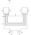
- the wiring member 10 will be described with reference to FIG. 2 in addition to FIG. FIG. 2 is a plan view showing the wiring member 10.
- the wiring member 10 is a vehicle wiring member that is connected to a component mounted on the vehicle and transmits electricity or light to and / or from the component. Therefore, the wiring member 10 includes a transmission member that transmits electricity or light.
- the wiring member 10 is formed flat.
- the wiring member with sheet material 12 includes a plurality of linear transmission members 14 and a sheet material 20.
- the linear transmission member 14 may be a linear member that transmits electricity or light.
- the linear transmission member 14 may be a general electric wire having a core wire and a coating around the core wire, or may be a bare conductor, a shielded wire, an enameled wire, a nichrome wire, an optical fiber, or the like.
- the linear transmission member 14 for transmitting electricity may be various signal lines or various power lines.
- the linear transmission member 14 has a transmission line main body that transmits electricity or light, and an outer cover that covers the transmission line main body.
- the linear transmission member 14 is a general electric wire 14 (hereinafter, simply referred to as an electric wire 14). That is, the electric wire 14 has a core wire as a transmission line main body, and an insulating coating as an outer cover that covers the transmission line main body.
- the core wire is composed of one or more strands.
- the strand is formed of a conductor such as copper, copper alloy, aluminum, and aluminum alloy.
- the core wire is composed of a plurality of strands, the plurality of strands are preferably twisted.
- the insulating coating is formed by extruding a resin material such as PVC (polyvinyl chloride) or PE (polyethylene) around the core wire.
- the electric wire 14 is a so-called round electric wire having a circular cross section.
- the connector C is provided at the end of the electric wire 14.
- the connector C is connected to a mating connector provided on, for example, an electric component.
- the connector C is provided on one side of the wiring member 10.
- an end of the electric wire 14 is housed in an electric wire housing of the housing H.
- the housing H may be directly fixed to the sheet member 20 or may not be fixed.
- the housing H is provided with a cassette portion Hc.
- One side portion of the wiring member 10 is fixed to the support member 30 by inserting and retaining the retaining portion (second retaining portion 60) provided on the support member 30 into the cassette portion Hc.
- a plurality of (two in the example shown in FIG. 2) connectors C are provided on one side of the wiring member 10.
- the plurality of connectors C are provided at intervals in the longitudinal direction of the rod-shaped member 100.
- the plurality of connectors C are provided so as to be connectable in the same direction, but may be connected in different directions.
- the sheet material 20 keeps the plurality of electric wires 14 in a flat state.
- the electric wires 14 are provided on the sheet material 20.
- a penetrating portion 44 to be described later penetrates the sheet material 20.
- the insertion hole 26 through which the penetrating portion 44 passes is formed in the sheet material 20 in advance.
- a part of the sheet member 20 is sandwiched between the support members 30.
- the sheet member 20 includes an arrangement main body 22 on which the electric wires 14 are arranged, and a fixing piece 24 sandwiched between the sheet members 20.
- An insertion hole 26 is formed in the fixing piece 24.
- the electric wire 14 and the sheet material 20 are fixed by fixing means.
- welding is employed as a means for fixing the electric wire 14 and the sheet material 20. That is, at least one of the electric wire 14 and the sheet material 20 has a resin material, and this resin material is melted and joined to the partner.
- the welding means is not particularly limited, and various welding means such as ultrasonic welding, heat and pressure welding, hot air welding, and high frequency welding can be employed.
- the sheet material 20 only needs to be able to fix the electric wire 14, and the material constituting the sheet material 20 is not particularly limited.
- the material forming the sheet material 20 may include, for example, a resin such as PVC, PE, PET (polyethylene terephthalate), or PP (polypropylene), or may include a metal such as aluminum or copper. Is also good.
- the material constituting the sheet material 20 may be set according to the fixing means.
- the disposition main body portion 22 of the sheet material 20 preferably contains a resin
- the disposition main body portion 22 of the sheet material 20 and the insulation coating of the electric wires 14 are preferably used. More preferably contains the same resin. Thereby, the insulating coating of the electric wire 14 and the resin sheet material 20 are melted together and joined to each other, so that the welding strength can be increased.
- the sheet material 20 may have a fiber such as a woven fabric, a knitted fabric, or a non-woven fabric, or may be a material formed by bonding without a fiber by extrusion molding, injection molding, or the like. . In the latter case, the sheet material 20 may be a foam formed by foaming, or may be formed so as to have a uniform cross section without foaming.
- the sheet material 20 may have a single-layer structure or a multi-layer structure. In the latter case, it is conceivable that the sheet material 20 has a first layer suitable for fixing (welding) the electric wire 14 and a second layer suitable for other functions such as a protection function, a soundproof function, and a shielding function. Can be In the latter case, layers having fibers or layers having no fibers may be overlapped, or a layer having fibers and a layer having no fibers may be overlapped.
- the sheet material 20 may be formed by bonding separately formed base materials, or the sheet material 20 may be formed by one extrusion molding or injection molding. May be done.
- the plurality of electric wires 14 are arranged in parallel on the sheet material 20.
- the path of the electric wire 14 on the sheet material 20 may be disposed linearly, may be disposed in a bent state, or may be set as appropriate.
- the path of the electric wire 14 has a portion arranged in a straight line and a portion arranged to be bent.
- each electric wire 14 is provided on the sheet material 20 so as to connect two connectors C provided separately on one side of the wiring member 10.
- a fixing piece 24 is provided on a side portion of the sheet material 20 opposite to the connector C side.
- two fixing pieces 24 protrude from an intermediate portion of the side edge of the disposition main body 22.
- Each fixing piece 24 is formed in a square shape.
- the fixing piece 24 may be formed according to the position, shape, and the like of the retaining portion (first retaining portion 40) of the support member 30 that sandwiches this portion.
- the wiring member 10 has flexibility. Due to this flexibility, the wiring member 10 is arranged to bend so as to follow the bent portion of the support member 30.
- the support member 30 is a member that fits into the bar-shaped member 100 such as a reinforcement, and has a portion that is bent along the circumferential direction on its outer surface.
- the wiring member 10 has flexibility in a direction arranged along the circumferential direction of the support member 30.
- the sheet material 20 has flexibility. At this time, even if the electric wires 14 are provided for the sheet material 20, the flexibility of the sheet material 20 is not impaired. Accordingly, the wiring member with sheet material 12 is flexible, and the wiring member with sheet material 12 is also bent along the circumferential direction with respect to the support member 30 having a portion bent in the circumferential direction. Can be set up.
- FIG. 3 is a perspective view showing the support member 30.
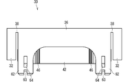
- FIG. 4 is a front view showing the support member 30.
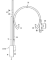
- FIG. 5 is a side view showing the support member 30.
- the support member 30 includes a fitting part 32, a mounting main body part 36, and a connecting part 38.
- the support member 30 further includes a retaining portion.
- the fitting portion 32 is formed in a cylindrical shape that is partially open in the circumferential direction so as to be fittable to the outer peripheral portion of the rod-shaped member 100.
- the fitting portion 32 is formed in a partial cylindrical shape larger than 180 degrees with respect to the circular rod-shaped member 100.
- the fitting part 32 is formed in a 240 degree partial cylindrical shape.
- a plurality of (two in the example shown in FIG. 1) fitting portions 32 are provided at intervals in the longitudinal direction of the rod-shaped member 100.
- the mounting body 36 is provided between the plurality of fitting portions 32.
- the mounting body 36 is formed so as to cover a region smaller than the fitting portion 32 in the periphery of the rod-shaped member 100.
- the mounting main body 36 is formed in a partial cylindrical shape of 180 degrees or less with respect to the circular rod-shaped member 100.
- the mounting main body 36 is formed in a 180 ° partial cylindrical shape.
- the fitting part 32 and the mounting main body part 36 are connected via a connecting part 38.
- the connecting portion 38 covers an area smaller than the fitting portion 32.
- the connecting portion 38 covers an area smaller than the mounting main body 36.
- the connecting portion 38 connects the fitting portion 32 and the mounting main body 36.
- the connecting portion 38 may connect the fitting portion 32 and the mounting main body portion 36 at a location other than this.
- the connecting portion 38 connects the fitting portion 32 and the mounting body portion 36 at a portion near one end of the fitting portion 32.
- the wiring member 1 with a support member includes a through portion 44 and a retaining portion 48.
- the penetrating portion 44 and the retaining portion 48 are portions for positioning and fixing the wiring member 10 to the support member 30.
- the penetrating portion 44 is a portion that penetrates the wiring member 10 in a state where the wiring member 10 is disposed outside the support member 30 (here, outside the mounting main body 36).
- the retaining portion 48 is provided outside the wiring member 10 without penetrating the wiring member 10.
- the retaining portion 48 is a portion for preventing the penetration portion 44 from coming off.
- the through portion 44 and the retaining portion 48 are provided on the support member 30. That is, the through portion 44 and the retaining portion 48 are integrally formed with the support member 30.
- the penetrating part 44 and the retaining part 48 constitute a part of the retaining part.
- the retaining portion is a portion for retaining the wiring member 10.
- a first retaining section 40 and a second retaining section 60 are provided as retaining sections.
- the penetration part 44 and the retaining part 48 are provided in the first retaining part 40.
- the first retaining portion 40 holds the sheet material 20 of the wiring member 10.
- a plurality of first retaining portions 40 are provided.
- the plurality of first retaining portions 40 are provided apart from each other along the longitudinal direction of the support member 30.
- the first retaining portion 40 includes an extension piece 42, a penetrating portion 44, a hinge 46, a retaining portion 48, and a locking portion 54.
- the extension piece 42 extends from the circumferential end of the mounting main body 36.
- the extension piece 42 extends from the circumferential end of the intermediate portion of the mounting main body 36.
- the extension piece 42 extends tangentially from the circumferential end of the mounting body 36.
- the penetrating portion 44 is provided on the outer surface of the extending piece 42 so as to protrude outward.
- the shape of the penetrating portion 44 is not particularly limited.
- the penetrating portion 44 is formed in a columnar shape or a frustum shape.
- the cross section of the penetrating portion 44 is formed in a circular shape, a square shape, or the like.
- the through portion 44 is formed in a cylindrical shape.
- the projecting dimension of the penetrating portion 44 is not particularly limited, but is preferably set so that the distal end portion of the penetrating portion 44 can be accommodated in the through hole 51 formed in the retaining portion 48. Further, it is preferable that the distal end portion of the through portion 44 is set so as not to protrude outward from the through hole 51 formed in the retaining portion 48.
- the hinge 46 is a portion that rotatably connects the extension piece 42 and the retaining portion 48.
- a hinge 46 is provided at the longitudinal end of the rod-shaped member 100 in the extension piece 42.
- the retaining portion 48 is rotatable around an axis along the direction in which the extension piece 42 extends from the mounting main body 36 (the tangential direction of the end of the mounting main body 36).
- the position of the hinge 46 is not limited to the above.
- the hinge 46 may be provided on the distal end edge of the extension piece 42 (the edge of the end opposite to the end connected to the mounting body 36).
- the retaining portion 48 is integrally formed with the support member 30 so as to be rotatable with respect to the extension piece 42 via the hinge 46.
- the retaining portion 48 can be opened and closed by rotating with respect to the extension piece 42.
- the retaining portion 48 is located on the end side of the mounting main body 36 where the extending piece 42 is not provided as shown in FIG.
- the retaining portion 48 overlaps the outside of the extending piece 42 in the closed state as shown in FIG.
- the retaining portion 48 includes a retaining piece 50 and a locked portion 52.
- the retaining piece 50 is a portion connected to the extending piece 42 via the hinge 46.
- the retaining piece 50 faces the extending piece 42 in the closed state.
- the retaining piece 50 is formed, for example, in a square shape.
- One side of the square retaining piece 50 is connected to the hinge 46, and the locked portion 52 is provided on the opposite side.
- a through-hole 51 is formed in the middle of the rectangular retaining portion 48.
- the through hole 51 is a concave portion in which a protruding portion of the through portion 44 that protrudes outward from the wiring member 10 is accommodated.
- a bottomed hole may be formed instead of the through hole 51 as a concave portion in which the through portion 44 fits.
- the locked portion 52 is formed so as to be lockable with the locking portion 54.
- the locked portion 52 will be described together with the locking portion 54.
- the locking portion 54 can be locked with the locked portion 52.
- the locking portion 54 is provided separately from the through portion 44.
- the locking portion 54 is provided on the opposite side of the hinge 46 with respect to the through portion 44.
- a locking projection is formed as the locking portion 54
- a locking recess is formed as the locked portion 52.
- the locking projection as the locking portion 54 includes a column portion 55 protruding outward on the outer surface of the extension piece 42 and a wing portion 56 provided at the tip of the column portion 55.
- the wing portion 56 extends from the tip of the column portion 55 toward the side of the column portion 55.
- the locking concave portion as the locked portion 52 is formed in a through-hole shape. Then, when the locking projection passes through the locking recess, at least one of the locking projection and the peripheral edge of the locking recess is elastically deformed and is allowed to pass. Then, after the locking projection has passed through the locking recess, the locking projection is elastically restored and the locking projection is hooked on the peripheral edge of the locking recess and locked.
- a guide surface for guiding the locking projection into the locking recess is formed on at least one of the tip of the locking projection and the peripheral edge of the locking recess.
- a guide surface for guiding the locking projection into the locking recess is formed at both the tip of the locking projection and the peripheral edge of the locking recess.
- the wiring member 10 is sandwiched between the extension piece 42 and the retaining portion 48 of the support member 30.
- the fixing piece 24 of the sheet material 20 is sandwiched between the extension piece 42 and the retaining portion 48 of the support member 30.
- the second retaining portion 60 is provided on the support member 30 on the opposite side of the first retaining portion 40 along the circumferential direction.
- a plurality of second retaining portions 60 are provided.
- the plurality of second retaining portions 60 are provided apart from each other along the longitudinal direction of the support member 30.
- the second retaining portion 60 retains the connector C of the wiring member 10. More specifically, the second retaining portion 60 retains the cassette portion Hc of the connector C.
- the second retaining portion 60 includes a retaining piece 62.
- a retaining recess 63 and a retaining hole 64 are formed in the retaining piece 62.
- the retaining recess 63 is provided at the tip of the retaining piece 62.
- the retaining recess 63 is formed such that the distal end edge of the retaining piece 62 is recessed toward the base end.
- the retaining hole 64 is provided at a position away from the retaining recess 63 toward the base end of the retaining piece 62.
- the retaining hole 64 is a through hole 51 formed to penetrate the retaining piece 62.
- FIGS. FIG. 6 and FIG. 7 are explanatory views showing a state in which the wiring member 10 is attached to the support member 30.
- the retaining portion 48 of the first retaining portion 40 is rotated from the open state to the closed state, and the locking portion 54 as the locked portion 52 is engaged with the locking concave portion as the locked portion 52.
- the stop projection is inserted and locked.
- the wiring member 10 is supported by the support member 30, and the wiring member with support member 1 is completed.
- the process of attaching the wiring member 10 to the support member 30 is performed, for example, by manufacturing the wiring member 1 with the support member in a factory different from the assembly factory for assembling the wiring member with the support member 1 to the vehicle. May be transported to Accordingly, in the assembly factory, the wiring member 10 can be assembled to the rod-shaped member 100 by a simple operation of fitting the support member 30 of the wiring member with support member 1 to the rod-shaped member 100.
- the wiring member 10 is supported by the support member 30 by the retaining portion 48 preventing the penetration portion 44 from coming off. At this time, since the penetrating portion 44 penetrates the wiring member 10, the wiring member 10 can be positioned on the support member 30. By supporting the support member 30 that supports the wiring member 10 on the rod-shaped member 100, the rod-shaped member 100 can support the flat wiring member 10.
- the penetrating portion 44 is formed integrally with the support member 30, the penetrating portion 44 is less likely to come off to the outer peripheral side of the wiring member 10 than when the penetrating portion 44 is separate from the support member 30. More specifically, when the penetrating portion 44 attempts to come off to the outer peripheral side of the wiring member 10, the extended piece of the support member 30 interferes with the wiring member 10 and is hard to come off.
- the retaining portion 48 is integrally formed with the supporting member 30 so as to be rotatable via the hinge 46, the number of parts can be reduced as compared with the case where the retaining portion 48 is different from the supporting member 30.
- the support member 30 further includes the locking portion 54 that locks with the locked portion 52 of the retaining portion 48, the retaining portion 48 can be retained. At this time, since the locking portion 54 is provided separately from the through portion 44, it is easy to obtain a fixed locking state.
- the flat wiring member 10 includes the plurality of electric wires 14 and the sheet material 20 through which the penetrating portion 44 penetrates while maintaining the plurality of electric wires 14 in a flat state, the flat wiring member 10 Can be formed.
- the wiring member 10 is sandwiched between the support member 30 and the retaining portion 48, the wiring member 10 is less likely to rattle.
- the support member 30, the penetrating portion 44, and the retaining portion 48 have been described as being integrally formed. However, this is not an essential configuration. For example, it is conceivable that the penetrating portion 44 and the retaining portion 48 are integrally formed, and the support member 30 is formed separately therefrom. This case will be described with reference to FIGS.
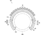
- FIG. 8 is a front view showing the wiring member with support member 101 according to the first modification.
- a first pin member 70 and a second pin member 80 are provided as pin members.
- the first pin member 70 includes a shaft portion 72 as a penetrating portion, a support plate 74 as a retaining portion, and a locking wing portion 76.
- a support plate 74 is provided at one end of the shaft 72, and a locking wing 76 is provided at the other end.
- the locking wing portion 76 is formed so as to gradually move away from the shaft portion 72 toward the support plate 74 side.
- the locking wing portion 76 is elastically deformable so that its tip approaches the shaft portion 72.
- the support member 130 is formed in a shape obtained by removing the retaining portions 40 and 60 from the support member 30. At this time, it is preferable that the support member 130 and the wiring member 110 have an insertion hole through which the shaft portion 72 is inserted.
- an insertion hole is formed in the mounting body 36 in the support member 130.
- the locking wing portion 76 can be inserted through this insertion hole by being elastically deformed.
- the support plate 74 is formed, for example, in a flat plate shape larger than the locking wing portion 76, and is formed so that the insertion hole cannot be inserted.
- the first pin member 70 is inserted into the insertion hole from the wiring member 110 side. That is, the locking wing portion 76 is first inserted into the insertion hole of the wiring member 110, and is inserted toward the support member 130 with elastic deformation. Thereafter, the shaft portion 72 is also inserted into the insertion hole following the locking wing portion 76. Then, the locking wing portion 76 elastically returns through the insertion hole formed in the support member 130 and locks on the periphery of the insertion hole, whereby the first pin member 70 holds the wiring member 110 to the support member 130. State.
- the second pin member 80 is formed in a shape in which a pair of locking pieces 82 are connected to a rod-shaped connecting portion 84.
- the second pin member 80 is formed in a so-called tag pin shape.
- the rod-shaped connecting portion 84 of the second pin member 80 forms a penetrating portion.
- the portion of the second pin member 80 that serves as the retaining portion changes depending on the way of fastening.
- the locking piece 82 located outside the wiring member 110 serves as a retaining portion.
- the second pin member 80 can be driven with a so-called tag gun. At this time, the state shown in FIG. 8 is obtained by driving only one of the locking pieces 82.
- both the pair of locking pieces 82 may be driven.
- the pair of locking pieces 82 are both located outside the support member 130.
- portions of the rod-shaped connecting portion 84 that are continuous with the pair of locking pieces 82 penetrate the support member 130 and the wiring member 110 at separate positions, and a portion therebetween is located outside the wiring member 110. Therefore, in this case, the rod-shaped connecting portion 84 has a portion forming a penetrating portion and a portion forming a retaining portion.
- an insertion hole through which the needle of the tag gun can be inserted may be formed in the support member 130 in advance, or may not be formed.
- FIG. 9 is a front view showing a wiring member 201 with a support member according to a second modification.
- the staple 90 is a component in which the penetration portion and the retaining portion are integrally formed.
- the staple 90 can be driven, for example, at a position where the pin members 70 and 80 are provided on the support member 130.
- the staple 90 is formed by bending one thin rod-like portion into a shape including a retaining portion 92, a penetrating portion 94, and a locking portion 96. More specifically, an intermediate portion of one thin rod-shaped portion serves as a retaining portion 92 that stays outside the wiring member 110. A portion connected to both sides of the retaining portion 92 is bent to form a penetrating portion 94 penetrating the wiring member 110 and the supporting member 130.
- the tip is bent from the penetrating portion 94 to form a locking portion 96 that locks to the outside of the support member 130.
- the staple 90 can be driven in with a so-called stapler or the like. At this time, an insertion hole through which the staples 90 pass through the support member 130 may be formed in advance, or may not be formed.
- the pin members 70, 80 and the staples 90 do not abut on the bar-shaped member 100.
- the pin members 70 and 80 and the staple 90 are provided in a portion along the rod member 100 such as the mounting body 36 of the support member 130, the surface of the support member 130 on the rod member 100 side or this portion It is preferable that the outer surface of the bar-shaped member 100 opposed to the first portion is formed to be concave. Further, for example, a portion of the support member 130 that is separated from the bar-shaped member 100 such as the extension piece 42 may be provided, and the pin members 70 and 80 and the staple 90 may be provided in this portion.
- the support member and the penetrating portion may be integrally formed, and the retaining portion may be formed separately from the above.
- the retaining portion 48 is separated from the support member 30 at the hinge 46 in the support member 30.
- another set of the locking portion 54 and the locked portion 52 is provided in place of the hinge 46 on the retaining portion 48 and the support member 30.
- the two retaining portions 48 are connected to form one member.
- the penetrating portion 44 may be provided between the two locking portions 54.
- the support member and the retaining portion may be integrally formed, and the through portion may be formed separately therefrom.
- a through hole 51 is formed at the position of the through portion 44, and the first pin member 70 serves as a through portion, and the support member 30 and the wiring member 10 are connected from the support member 30 side. It is conceivable that the locking wing portion 76 is inserted and locked in the through hole 51 of the retaining portion 48.
- the support member, the penetrating portion, and the retaining portion may be formed separately from each other.
- the first pin member 70 is inserted in the support member 130 in the opposite direction to the example shown in FIG. 8, and the retaining portion has a shape in which a through hole is formed in a flat plate outside the wiring member 110.
- the retaining portion has a shape in which a through hole is formed in a flat plate outside the wiring member 110.
- the retaining wing portion 76 of the first pin member 70 functions as the retaining portion 54.
- the locking portion 54 is integral with the through portion.
- the support member 30 is provided with a locking portion 54 at the tip of the through portion 44 so as to lock in the through hole 51 of the retaining portion 48.
- the locking projection is formed as the locking portion 54 and the locking concave portion is formed as the locked portion 52, this is not an essential configuration.
- a locking concave portion may be formed as the locking portion 54, and a locking protrusion may be formed as the locked portion 52.
- both the locking portion 54 and the locked portion 52 may be formed with locking projections.
- the wiring member 10 has been described as the wiring member 12 with the sheet material, this is not an essential configuration.
- the wiring member 10 is a so-called FFC (flexible flat cable) in which a plurality of core wires are collectively covered with a single covering, or a so-called FPC (flexible printed circuit board) in which a circuit is formed on a conductor foil bonded to an insulating film serving as a base. And so on.
- FFC flexible flat cable
- FPC flexible printed circuit board
- the configuration is not limited to the above.
- the outer shape of the linear transmission member 14 may be formed in a rectangular cross section. In this case, the contact area between the sheet member 20 and the linear transmission member 14 can be easily increased.
- the means for fixing the linear transmission member 14 and the sheet material 20 for example, the linear transmission member 14 and the sheet material 20 may be joined by an adhesive, an adhesive tape, or the like.
- the linear transmission member 14 may be sewn to the sheet material 20 with a sewing thread.
- the wiring body with sheet material 12 may have a cover that covers the linear transmission member 14 from the side opposite to the sheet material 20.
- both ends of the electric wire 14 are connected to the connector C supported by the support member 30, but this is not an essential configuration. It is also conceivable that at least one end of the electric wire 14 is connected to the connector C that is not supported by the support member 30. In this case, it is conceivable that the sheet material 20 extends together with the electric wire 14, or that the electric wire 14 extends outward from the sheet material 20. In this case, the electric wire 14 may extend along the rod-shaped member 100 or may extend away from the rod-shaped member 100.
- one wiring member 10 has been supported by one support member 30, this is not an essential configuration.
- one wiring member 10 may be supported by a plurality of support members 30. More specifically, when the plurality of support members 30 are attached at intervals along the longitudinal direction of the rod-shaped member 100, one wiring member 10 may be supported across the plurality of support members 30. Can be Further, for example, at least a part of the plurality of wiring members 10 may be supported by one support member 30.
- one wiring member 10 is supported on the support member 30 using the first retaining portion 40 and the second retaining portion 60 on one end in the longitudinal direction, and the first retaining member 40 and the It is conceivable that another wiring member 10 is supported on the support member 30 using the retaining portion 40 and the second retaining portion 60.
- the support member 30 has been described as including the mounting body 36, this is not an essential configuration.
- the support member may be composed of only the fitting portion 32 or only the fitting portion 32 and the protrusion 34.
- the wiring member 10 may be fixed to the fitting portion 32.
- the locking portion 54 and the locked portion 52 are locked to keep the retaining portion 48 in the closed state, but this is not an essential configuration.
- the retaining portion 48 is joined to a part of the wiring member 10 or the support member 30 and the retaining portion 48 is maintained in a closed state.
- the wiring member 10 has been described as being sandwiched between the support member 30 and the retaining portion 48 in the embodiment, this is not an essential configuration.
- the wiring member 10 may not be sandwiched between the support member 30 and the retaining portion 48 in some cases.
Landscapes
- Engineering & Computer Science (AREA)
- Architecture (AREA)
- Civil Engineering (AREA)
- Structural Engineering (AREA)
- Mechanical Engineering (AREA)
- General Engineering & Computer Science (AREA)
- Details Of Indoor Wiring (AREA)
- Installation Of Indoor Wiring (AREA)
- Connection Of Plates (AREA)
- Mutual Connection Of Rods And Tubes (AREA)
- Insulated Conductors (AREA)
Abstract
棒状部材に偏平な配線部材を支持させるのに適した技術を提供することを目的とする。支持部材付配線部材は、偏平に形成された配線部材と、棒状部材の外周部に対して嵌合可能に周方向一部分で開口した筒状に形成された嵌合部を含む支持部材と、前記配線部材が前記支持部材の外側に配設された状態で、前記配線部材を貫通する貫通部と、前記配線部材を貫通せずに前記配線部材に対して外側に設けられ、前記貫通部の抜け止めを図る抜止部と、を備える。例えば、前記貫通部が前記支持部材と一体成形されていることが考えられる。
Description
この発明は、棒状部材に配線部材を支持させる技術に関する。
特許文献1は、棒状部材に配線部材を支持させる技術を開示している。特許文献1に記載のワイヤーハーネス支持部材は、棒状部材を抱え込む形で嵌合可能な嵌合部と、嵌合部の外周に嵌合部と一体に設けられて配線部材としてのワイヤーハーネスを覆う保護部とを備える。
しかしながら、特許文献1に記載のワイヤーハーネス支持部材は、電線束のような丸断面のワイヤーハーネスを支持することに適するが、偏平な配線部材を支持することに向かない。
そこで本発明は、棒状部材に偏平な配線部材を支持させるのに適した技術を提供することを目的とする。
上記課題を解決するため、第1の態様に係る支持部材付配線部材は、偏平に形成された配線部材と、棒状部材の外周部に対して嵌合可能に周方向一部分で開口した筒状に形成された嵌合部を含む支持部材と、前記配線部材が前記支持部材の外側に配設された状態で、前記配線部材を貫通する貫通部と、前記配線部材を貫通せずに前記配線部材に対して外側に設けられ、前記貫通部の抜け止めを図る抜止部と、を備える。
第2の態様に係る支持部材付配線部材は、第1の態様に係る支持部材付配線部材であって、前記貫通部が前記支持部材と一体成形されている。
第3の態様に係る支持部材付配線部材は、第1又は第2の態様に係る支持部材付配線部材であって、前記抜止部がヒンジを介して回動可能に前記支持部材と一体成形されている。
第4の態様に係る支持部材付配線部材は、第1から第3のいずれか1つの態様に係る支持部材付配線部材であって、前記支持部材は、前記抜止部の被係止部と係止する係止部をさらに含む。
第5の態様に係る支持部材付配線部材は、第4の態様に係る支持部材付配線部材であって、前記係止部は前記貫通部と別に設けられている。
第6の態様に係る支持部材付配線部材は、第1から第5のいずれか1つの態様に係る支持部材付配線部材であって、前記配線部材は、複数の線状伝送部材と、前記複数の線状伝送部材を偏平な状態に保つと共に、前記貫通部が貫通するシート材とを含む。
第7の態様に係る支持部材付配線部材は、第1から第6のいずれか1つの態様に係る支持部材付配線部材であって、前記配線部材は前記支持部材と前記抜止部との間に挟持されている。
各態様によると、抜止部によって貫通部の抜け止めがなされることによって配線部材が支持部材に支持された状態となる。このとき貫通部が配線部材を貫通していることによって、配線部材を支持部材に位置決めすることができる。配線部材を支持するこの支持部材を棒状部材に支持させることによって、棒状部材に偏平な配線部材を支持させることができる。
第2の態様によると、貫通部が支持部材と別体の場合に比べて貫通部が配線部材の外周側に抜けにくい。
第3の態様によると、抜止部が支持部材と別の場合に比べて部品点数を削減できる。
第4の態様によると、抜止部を係止させることができる。
第5の態様によると、一定の係止状態を得やすい。
第6の態様によると、汎用の電線を用いて偏平な配線部材を形成することができる。
第7の態様によると、配線部材ががたつき難くなる。
{実施形態}
以下、実施形態に係る支持部材付配線部材について説明する。図1は、実施形態に係る支持部材付配線部材1を示す斜視図である。
以下、実施形態に係る支持部材付配線部材について説明する。図1は、実施形態に係る支持部材付配線部材1を示す斜視図である。
支持部材付配線部材1は、車両に設けられた棒状部材100に組付けられる。この棒状部材100について先に説明する。
係る棒状部材100が、リインフォースメントであるものとして説明する。特に棒状部材100がインストルメントパネルの裏側に設けられるインパネリインフォースメントであるものとして説明する。もっとも棒状部材100は、車両に設けられる棒状の部材であればよく、例えば、ピラーなど、リインフォースメント以外の部材であってもよい。また図1に示す例では、棒状部材100が円筒状に形成されているが、このことは必須の構成ではない。棒状部材100は、角筒状、円柱状、角柱状などであってもよい。
支持部材付配線部材1は、配線部材10と、支持部材30とを備える。配線部材10は、支持部材30に支持されている。支持部材30は、棒状部材100に取付け可能である。従って、支持部材付配線部材1における支持部材30を棒状部材100に取付けることによって、配線部材10を簡易に棒状部材100に組付けることが可能とされる。
配線部材10について、図1に加えて図2を参照しつつ説明する。図2は、配線部材10を示す平面図である。
配線部材10は、車両に搭載された部品につながれて、当該部品に及び/又は当該部品から電気又は光を伝送する車両用の配線部材である。従って、配線部材10は、電気又は光を伝送する伝送部材を含む。配線部材10は、偏平に形成されている。以下では、配線部材10がシート材付配線体12であるものとして説明する。シート材付配線体12は、複数の線状伝送部材14と、シート材20とを含む。
線状伝送部材14は、電気又は光を伝送する線状の部材であればよい。例えば、線状伝送部材14は、芯線と芯線の周囲の被覆とを有する一般電線であってもよいし、裸導線、シールド線、エナメル線、ニクロム線、光ファイバ等であってもよい。電気を伝送する線状伝送部材14としては、各種信号線、各種電力線であってもよい。
ここでは線状伝送部材14は、電気又は光を伝送する伝送線本体と、伝送線本体を覆う外皮とを有する。以下では、線状伝送部材14が一般電線14(以下、単に電線14と呼ぶ)であるものとして説明する。つまり電線14は、伝送線本体としての芯線と、伝送線本体を覆う外皮としての絶縁被覆とを有する。
芯線は、1本又は複数本の素線で構成される。素線は、銅、銅合金、アルミニウム、アルミニウム合金等の導体で形成される。芯線が複数本の素線で構成される場合、複数本の素線は撚られていることが好ましい。絶縁被覆は、PVC(ポリ塩化ビニル)、PE(ポリエチレン)などの樹脂材料が芯線の周囲に押出成形されるなどして形成される。ここでは電線14は、横断面が円形のいわゆる丸電線である。
ここでは電線14の端部にはコネクタCが設けられている。このコネクタCが、例えば電気部品などに設けられた相手側コネクタに接続される。ここでは、配線部材10の一側方部にコネクタCが設けられている。係るコネクタCは、電線14の端部がハウジングHの電線収容部に収容されて形成されている。このハウジングHは、シート材20に直接固定されていてもよいし、固定されていなくてもよい。ハウジングHには、カセット部Hcが設けられている。支持部材30に設けられた留部(第2留部60)がカセット部Hcに挿し込まれて留められることによって、配線部材10の一側方部が支持部材30に固定される。
ここでは配線部材10の一側方部に複数(図2に示す例では2つ)のコネクタCが設けられている。複数のコネクタCは、棒状部材100の長手方向に間隔をあけて設けられる。複数のコネクタCは、同じ向きに接続可能に設けられているが、異なる向きに接続されるものであってもよい。
シート材20は、複数の電線14を偏平な状態に保つ。ここでは、シート材20上に電線14が配設される。シート材20を後述する貫通部44が貫通している。このときシート材20には、貫通部44を通す挿通孔26が予め形成されている。またシート材20は、その一部が支持部材30に挟持される。シート材20は、電線14が配設される配設本体部22と、シート材20に挟持される固定片24とを含む。固定片24に挿通孔26が形成されている。
電線14とシート材20とは、固定手段によって固定されている。電線14とシート材20との固定手段として、ここでは溶着が採用されている。つまり、電線14とシート材20とのうち少なくとも一方が樹脂材料を有し、この樹脂材料が溶けて相手側に接合される。
係る溶着手段としては、特に限定されるものではなく、超音波溶着、加熱加圧溶着、熱風溶着、高周波溶着など種々の溶着手段を採用することができる。
シート材20は電線14を固定できればよく、シート材20を構成する材料は、特に限定されるものではない。シート材20を構成する材料は、例えば、PVC、PE、PET(ポリエチレンテレフタレート)、PP(ポリプロピレン)などの樹脂を含むものであってもよいし、アルミニウム又は銅などの金属を含むものであってもよい。
シート材20を構成する材料は、固定手段に応じて設定されるとよい。例えば、シート材20と電線14の絶縁被覆とが溶着される場合、シート材20の配設本体部22が樹脂を含むことが好ましく、シート材20の配設本体部22と電線14の絶縁被覆とは同じ樹脂を含むことがより好ましい。これにより、電線14の絶縁被覆と、樹脂製のシート材20とが共に溶けて相互に接合され、もって溶着強度を高めることができる。
シート材20は、織布、編布、不織布などの繊維を有するものであってもよいし、押出成形または射出成形などによって繊維を有さずに結合されて形成されたものであってもよい。後者の場合、シート材20は、発泡成形された発泡体であってもよいし、発泡成形されずに一様断面を有するように成形されたものであってもよい。
またシート材20は、1層構造を有するものであってもよいし、複数層構造を有するものであってもよい。後者の場合、シート材20は、電線14の固定(ここでは溶着)に向いた第1層と、保護機能、防音機能、シールド機能など他の機能に向いた第2層とを有することが考えられる。また後者の場合、繊維を有する層同士又は繊維を有しない層同士が重ねられてもよいし、繊維を有する層と繊維を有しない層とが重ねられてもよい。
シート材20が複数層構造を有するものである場合、別々に成形された基材を貼り合わせてシート材20が成形されてもよいし、一の押出成形または射出成形などによってシート材20が成形されてもよい。
複数の電線14は、シート材20上に並設されている。シート材20上における電線14の経路は、直線状に配設されていてもよいし、曲がって配設されていてもよいし、適宜設定されていればよい。図2に示す例では、電線14の経路は、直線状に配設される部分と、曲がって配設される部分とを有する。ここでは、各電線14が配線部材10の一側方部において離れて設けられた2つのコネクタCを接続するようにシート材20上に配設されている。
シート材20のうちコネクタC側とは反対側の側方部に固定片24が設けられている。図2に示す例では、2つの固定片24が、配設本体部22の側縁の中間部分から突出している。また各固定片24は、方形状に形成されている。もっとも、固定片24の位置、形状等はこれに限られない。固定片24は、この部分を挟持する支持部材30の留部(第1留部40)の位置、形状等に応じて形成されているとよい。
配線部材10は、可撓性を有している。この可撓性により、配線部材10は、支持部材30の曲がっている部分に追従するように曲がって配設されている。
より詳細には、ここでは支持部材30がリインフォースメントなどの棒状部材100に嵌合する部材であり、その外面に周方向に沿って曲がっている部分を有する。配線部材10は、支持部材30の周方向に沿って配設される方向に、可撓性を有する。より具体的には、ここではシート材20が可撓性を有している。このときシート材20に対して電線14が配設されていても、シート材20の可撓性を阻害しない。これにより、シート材付配線体12は、可撓性を有しており、周方向に曲がる部分を有する支持部材30に対してもその周方向に沿ってシート材付配線体12を曲げて配設することができる。
図1に加えて図3乃至図5を参照しつつ、支持部材30について説明する。図3は、支持部材30を示す斜視図である。図4は、支持部材30を示す正面図である。図5は、支持部材30を示す側面図である。
支持部材30は、嵌合部32、載置本体部36、連結部38を含む。ここでは、支持部材30は、留部をさらに含む。
嵌合部32は、棒状部材100の外周部に対して嵌合可能に周方向一部分で開口した筒状に形成されている。例えば嵌合部32は、円形状の棒状部材100に対して180度より大きい部分筒状に形成される。ここでは嵌合部32は、240度の部分筒状に形成されている。支持部材30が棒状部材100に取付けられる際、嵌合部32の開口を通じて棒状部材100が嵌合部32内に挿通される。この際、嵌合部32は、開口が広がるように弾性変形可能であり、これにより、嵌合部32の内部に棒状部材100が収められる。
嵌合部32の周方向端部には、棒状部材100の外周面に形成された凹部(図示省略)に嵌まる突起34が形成されている。嵌合部32内に棒状部材100が収められた状態で、突起34が凹部に嵌まることによって、支持部材30が棒状部材100に対して、長手方向及び周方向に位置ずれすることを抑制できる。
ここでは、棒状部材100の長手方向に間隔をあけて複数(図1に示す例では2つ)の嵌合部32が設けられている。そして、複数の嵌合部32の間に載置本体部36が設けられている。
載置本体部36は、棒状部材100の周囲のうち嵌合部32よりも小さい領域を覆うように形成されている。例えば載置本体部36は、円形状の棒状部材100に対して180度以下の部分筒状に形成される。ここでは載置本体部36は、180度の部分筒状に形成されている。
嵌合部32と載置本体部36とは、連結部38を介して繋がっている。連結部38は、嵌合部32よりも小さい領域を覆う。また連結部38は載置本体部36よりも小さい領域を覆う。これにより、支持部材30が棒状部材100に取付けられるときに嵌合部32がその開口を広げるように弾性変形する際に、載置本体部36が嵌合部32の弾性変形を阻害しにくくなっている。図3に示す例では、連結部38は、円形状の棒状部材100に対して60度分を覆う。
ここでは嵌合部32の開口の中心と載置本体部36の開口の中心とが一致している。その開口の中心の反対側で連結部38は、嵌合部32と載置本体部36とを繋げている。もちろん連結部38は、これ以外の箇所で嵌合部32と載置本体部36とを繋げている場合もあり得る。例えば、連結部38は、嵌合部32の一方端部寄りの部分で嵌合部32と載置本体部36とを繋げていることなども考えられる。
支持部材付配線部材1は、貫通部44と、抜止部48とを備える。貫通部44及び抜止部48は、配線部材10を、支持部材30に位置決めしつつ留めるための部分である。貫通部44は、配線部材10が支持部材30の外側(ここでは載置本体部36の外側)に配設された状態で、配線部材10を貫通する部分である。抜止部48は、配線部材10を貫通せずに配線部材10に対して外側に設けられる。抜止部48は、貫通部44の抜け止めを図る部分である。ここでは、貫通部44及び抜止部48が支持部材30に設けられている。つまり貫通部44及び抜止部48が支持部材30と一体成形されている。貫通部44及び抜止部48は、留部の一部を構成している。
留部は、配線部材10を留める部分である。留部としてここでは、第1留部40と第2留部60とが設けられている。貫通部44及び抜止部48は、第1留部40に設けられている。
第1留部40は、配線部材10のシート材20を留める。ここでは第1留部40が複数設けられている。複数の第1留部40は支持部材30の長手方向に沿って離れて設けられている。第1留部40は延出片42と、貫通部44と、ヒンジ46と、抜止部48と、係止部54とを含む。
延出片42は、載置本体部36の周方向端部から延出する。ここでは、載置本体部36の中間部分の周方向端部から延出片42が延出している。延出片42は、載置本体部36の周方向端部から接線方向に延出している。
貫通部44は、延出片42の外面に外向きに延出するように突設されている。貫通部44の形状は特に限定されるものではない。例えば貫通部44は、柱状又は錐台形状等に形成される。また貫通部44の横断面は、円形状又は角形状等に形成される。ここでは貫通部44は円柱形状に形成されている。貫通部44の突出寸法は特に限定されないが、貫通部44の先端側部分が抜止部48に形成された貫通孔51に収まることが可能に設定されているとよい。さらに、貫通部44の先端側部分が抜止部48に形成された貫通孔51より外方に突出しないように設定されているとよい。
ヒンジ46は、延出片42と抜止部48とを回動可能につなぐ部分である。ここでは、延出片42のうち棒状部材100の長手方向端縁部にヒンジ46が設けられている。これにより、載置本体部36からの延出片42の延出方向(載置本体部36の端部の接線方向)に沿った軸周りに抜止部48が回動可能とされる。もちろんヒンジ46の位置は上記したものに限られない。例えばヒンジ46は、延出片42の先端縁部(載置本体部36に連なる端部とは反対側の端部の縁部)に設けられていてもよい。
抜止部48は、ヒンジ46を介して延出片42に対して回動可能に支持部材30と一体成形されている。抜止部48は、延出片42に対して回動することによって開閉可能とされる。抜止部48は、開状態で、図3に示すように延出片42の設けられなかった載置本体部36の端部側に位置する。また抜止部48は、閉状態で、図1に示すように延出片42の外側に重なる。抜止部48は、抜止片50と、被係止部52とを含む。
抜止片50はヒンジ46を介して延出片42と繋がる部分である。抜止片50は、閉状態で、延出片42と対向する。抜止片50は、例えば方形状に形成されている。そして方形状の抜止片50の一辺がヒンジ46と繋がり、その反対の一辺に被係止部52が設けられている。また方形状の抜止部48の中間に貫通孔51が形成されている。貫通孔51は、貫通部44のうち配線部材10より外方に突出する突出部が収まる凹部である。もっとも貫通部44が収まる凹部として貫通孔51ではなく有底穴が形成されていてもよい。
被係止部52は、係止部54と係止可能に形成されている。被係止部52については係止部54と共に説明する。
係止部54は、被係止部52と係止可能である。ここでは係止部54は、貫通部44と別に設けられている。特にここでは係止部54は、貫通部44に対してヒンジ46とは反対側に設けられている。ここでは、係止部54として係止突起が形成され、被係止部52として係止凹部が形成されている。
係止部54としての係止突起は、延出片42の外面に外向きに突設された柱部55と、柱部55の先端に設けられた羽部56とを含む。羽部56は、柱部55の先端から柱部55の側方に向けて延びる。
被係止部52としての係止凹部は、貫通孔状に形成されている。そして、係止突起が係止凹部を通過する際に、係止突起と係止凹部の周縁部とのうち少なくとも一方が弾性変形して通過可能とされる。そして、係止突起が係止凹部を通過した後、弾性復帰して係止突起が係止凹部の周縁部に引っ掛かって係止する。係止突起の先端及び係止凹部の周縁部の少なくとも一方には係止突起を係止凹部にガイドするガイド面が形成されている。ここでは、係止突起の先端及び係止凹部の周縁部の両方に係止突起を係止凹部にガイドするガイド面が形成されている。
支持部材30における延出片42と抜止部48との間に配線部材10が挟持されている。ここでは支持部材30における延出片42と抜止部48との間にシート材20の固定片24が挟持されている。
第2留部60は、支持部材30において第1留部40とは周方向に沿った反対側に設けられている。ここでは第2留部60が複数設けられている。複数の第2留部60は支持部材30の長手方向に沿って離れて設けられている。第2留部60は、配線部材10のコネクタCを留める。より詳細には、第2留部60は、コネクタCのカセット部Hcを留める。第2留部60は、留片62を含む。留片62に留凹部63と留孔64が形成されている。
留片62は、載置本体部36のうち第1留部40の延出片42が延びる周方向端部とは反対側の周方向端部から延出するように設けられている。留片62は、載置本体部36の長手方向端部の位置で載置本体部36の周方向端部からその接線方向に延出するように設けられている。留片62と延出片42とは例えば平行である。留片62は、開状態の抜止部48と対向している。留片62は、コネクタCのカセット部Hcに挿し込み可能とされる。
留凹部63は、留片62の先端に設けられている。留凹部63は、留片62の先端縁部が基端部側に凹むように形成されている。留孔64は、留凹部63に対して留片62の基端部側に離れた位置に設けられている。留孔64は留片62を貫通するように形成された貫通孔51である。留片62がコネクタCのカセット部Hcに挿し込まれた状態で、留孔64にコネクタCのカセット部Hcに設けられた係止片が係止することによって、コネクタが第2留部60に留められた状態となる。
<取付方法>
図6及び図7を参照しつつ、配線部材10を支持部材30に取付ける方法について説明する。図6及び図7は、配線部材10を支持部材30に取付ける様子を示す説明図である。
図6及び図7を参照しつつ、配線部材10を支持部材30に取付ける方法について説明する。図6及び図7は、配線部材10を支持部材30に取付ける様子を示す説明図である。
まず支持部材30に対して図6に示すようにコネクタCのカセット部Hcを第2留部60に留める。この状態で、シート材付配線体12を載置本体部36の外周部に沿って支持部材30に巻付ける。その後、シート材20の固定片24に形成された挿通孔26に貫通部44を貫通させる。これにより、図7に示すような状態となる。
この後、図7の矢印に示すように、第1留部40の抜止部48を開状態から閉状態へ回動させ、被係止部52としての係止凹部に係止部54としての係止突起を挿通係止させる。
以上より、配線部材10が支持部材30に支持された状態となり、支持部材付配線部材1が完成となる。この支持部材30への配線部材10の取付工程は、例えば、支持部材付配線部材1を車両に組付ける組付工場とは別の工場で製造されて、支持部材付配線部材1が組付工場に搬送されることが考えられる。これにより、組付工場においては、支持部材付配線部材1における支持部材30を棒状部材100へ嵌合させるとの簡易な作業によって配線部材10を棒状部材100に組み付けることができる。
以上のように構成された支持部材付配線部材1によると、抜止部48によって貫通部44の抜け止めがなされることによって配線部材10が支持部材30に支持された状態となる。このとき貫通部44が配線部材10を貫通していることによって、配線部材10を支持部材30に位置決めすることができる。配線部材10を支持するこの支持部材30を棒状部材100に支持させることによって、棒状部材100に偏平な配線部材10を支持させることができる。
また貫通部44が支持部材30と一体成形されているため、貫通部44が支持部材30と別体の場合に比べて貫通部44が配線部材10の外周側に抜けにくい。より詳細には、貫通部44が配線部材10の外周側に抜けようとした場合に、支持部材30の延出片が配線部材10に干渉し、抜けにくくなっている。
また抜止部48がヒンジ46を介して回動可能に支持部材30と一体成形されているため、抜止部48が支持部材30と別の場合に比べて部品点数を削減できる。
また支持部材30は、抜止部48の被係止部52と係止する係止部54をさらに含むため、抜止部48を係止させることができる。このとき、係止部54は貫通部44と別に設けられているため、一定の係止状態を得やすい。
また配線部材10は、複数の電線14と、複数の電線14を偏平な状態に保つと共に、貫通部44が貫通するシート材20とを含むため、汎用の電線14を用いて偏平な配線部材10を形成することができる。
また配線部材10は支持部材30と抜止部48との間に挟持されているため、配線部材10ががたつき難くなる。
{変形例}
実施形態において、支持部材30、貫通部44、抜止部48が一体成形されているものとして説明してきたが、このことは必須の構成ではない。例えば、貫通部44、抜止部48が一体成形され、支持部材30がこれとは別体に成形されている場合も考えられる。この事例について図8及び図9を参照にしつつ説明する。
実施形態において、支持部材30、貫通部44、抜止部48が一体成形されているものとして説明してきたが、このことは必須の構成ではない。例えば、貫通部44、抜止部48が一体成形され、支持部材30がこれとは別体に成形されている場合も考えられる。この事例について図8及び図9を参照にしつつ説明する。
図8は、第1変形例に係る支持部材付配線部材101を示す正面図である。
ここでは貫通部、抜止部が一体成形された部品が、ピン部材である事例である。ピン部材として、第1ピン部材70と第2ピン部材80とが設けられている。
第1ピン部材70は、貫通部としての軸部72と抜止部としての支持板74と係止羽部76とを含む。軸部72の一端に支持板74が設けられ、他端に係止羽部76が設けられている。係止羽部76は、支持板74側に行くにつれて徐々に軸部72から離れるように形成されている。係止羽部76は、その先端が軸部72に近づくように弾性変形可能である。
支持部材130は、支持部材30から留部40、60を除いた形状に形成されている。このとき支持部材130、配線部材110には、軸部72が挿通される挿通孔が形成されているとよい。例えば支持部材130において載置本体部36に挿通孔が形成される。係止羽部76は、弾性変形することによってこの挿通孔を挿通可能とされる。一方、支持板74は例えば係止羽部76よりも大きい平板状に形成され、挿通孔を挿通不可に形成される。
第1ピン部材70は、配線部材110側から挿通孔に挿通される。つまり係止羽部76がまず配線部材110の挿通孔に挿通され、弾性変形を伴いつつ支持部材130側に挿通されて行く。この後、軸部72も係止羽部76に続いて挿通孔に挿通される。そして、係止羽部76が支持部材130に形成された挿通孔を抜けて弾性復帰し、挿通孔の周縁に係止することによって第1ピン部材70が支持部材130に配線部材110を留めた状態となる。
第2ピン部材80は、一対の係止片82を棒状連結部84が繋いだ形状に形成されている。第2ピン部材80は、いわゆるタグピン状に形成されている。第2ピン部材80のうち棒状連結部84が貫通部を成す。第2ピン部材80のうち抜止部となる部分は、留め方によって変わる。
より詳細には、図8に示す例では、棒状連結部84が配線部材110及び支持部材130を貫通した状態で、一方の係止片82が配線部材110の外方に位置し、他方の係止片82が支持部材130の外方に位置する。この場合、配線部材110の外方に位置する係止片82が抜止部となる。
例えば第2ピン部材80は、いわゆるタグガンで打ち込むことができる。このとき、一方の係止片82のみを打ち込むことによって図8に示すような状態となる。
これに対して、一対の係止片82を両方打ち込む場合もあり得る。この場合、一対の係止片82が共に支持部材130の外方に位置する。そして棒状連結部84のうち一対の係止片82に連なる部分が、それぞれ離れた位置で支持部材130及び配線部材110を貫通し、その間の部分が配線部材110の外方に位置する。従って、この場合、棒状連結部84が貫通部を成す部分と、抜止部を成す部分とを有する。
なお、タグガンによって第2ピン部材80を打ち込むに当たり、支持部材130にタグガンの針を挿通可能な挿通孔が予めあけられている場合もあり得るし、あけられていない場合もあり得る。
図9は、第2変形例に係る支持部材付配線部材201を示す正面図である。
ここでは貫通部、抜止部が一体成形された部品が、ステープル90である事例である。かかるステープル90は、例えば支持部材130においてピン部材70、80を設ける位置に打ち込むことができる。ステープル90は、一の細棒状部が抜止部92と貫通部94と係止部96とを含む形状に曲げられて形成されている。より詳細には、一の細棒状部の中間部が配線部材110の外方に留まる抜止部92とされる。抜止部92の両側に連なる部分が曲げられて配線部材110及び支持部材130を貫通する貫通部94とされる。貫通部94より先端が曲げられて支持部材130の外方に係止する係止部96とされる。ステープル90は、いわゆるステープラ―などで打ち込むことができる。このとき、支持部材130にステープル90を通す挿通孔が予めあけられていてもよいし、あけられていなくてもよい。
なお、支持部材130にピン部材70、80、ステープル90が設けられるに当たり、ピン部材70、80、ステープル90が棒状部材100と当接しないようにされていることが好ましい。例えば、支持部材130の載置本体部36など棒状部材100に沿う部分に、ピン部材70、80、ステープル90が設けられる場合、支持部材130のこの部分の棒状部材100側の面、又はこの部分に対向する棒状部材100の外面が凹んで形成されているとよい。また例えば、支持部材130に上記延出片42などの棒状部材100から離れる部分が設けられ、この部分にピン部材70、80、ステープル90が設けられていてもよい。
上記のほかに例えば、支持部材、貫通部が一体成形され、抜止部がこれとは別体に成形されている場合もあり得る。この場合の事例として例えば、上記支持部材30において、ヒンジ46の部分で抜止部48が支持部材30から離されていることが考えられる。この場合、例えば抜止部48及び支持部材30に、ヒンジ46の代わりとして係止部54及び被係止部52がもう一組設けられていることが考えられる。またこの場合、例えば、2つの抜止部48が連なって一の部材とされていることが考えられる。この場合、2つの係止部54の間に貫通部44が設けられているとよい。
また例えば、支持部材、抜止部が一体成形され、貫通部がこれとは別体に成形されている場合もあり得る。この場合の事例として例えば、上記支持部材30において、貫通部44の位置に貫通孔51が形成され、貫通部として上記第1ピン部材70が、支持部材30側から支持部材30と配線部材10とを貫通しており、その係止羽部76が抜止部48の貫通孔51に挿通係止していることが考えられる。
また例えば、支持部材、貫通部、抜止部がそれぞれ別体に成形されている場合もあり得る。この場合の事例として例えば、支持部材130において第1ピン部材70が図8に示す例とは逆向きに挿し込まれ、配線部材110の外側で平板に貫通孔が形成された形状を有する抜止部が、第1ピン部材70の係止羽部76に係止していることが考えられる。
上記支持部材、貫通部、抜止部がそれぞれ別体に成形されている事例において、第1ピン部材70の係止羽部76が、係止部54として機能する。この場合のように、係止部54が貫通部と一体であることも考えられる。つまり、これまで係止部が貫通部と別に設けられているものとして説明してきたが、このことは必須の構成ではなく、係止部が貫通部と一体であることも考えられる。上記事例のほか、例えば、支持部材30において、貫通部44の先端に係止部54が設けられて、抜止部48の貫通孔51に係止するように構成されていることも考えられる。
またこれまで係止部54として係止突起が形成され、被係止部52として係止凹部が形成されているものとして説明してきたが、このことは必須の構成ではない。例えば、係止部54として係止凹部が形成され、被係止部52として係止突起が形成されていてもよい。また例えば、係止部54及び被係止部52として共に係止突起が形成されていてもよい。
またこれまで配線部材10がシート材付配線体12であるものとして説明したが、このことは必須の構成ではない。配線部材10は、複数の芯線が一の被覆で一括被覆されたいわゆるFFC(フレキシブルフラットケーブル)、又はベースとなる絶縁フィルムに貼り合わされた導体箔に回路が形成されたいわゆるFPC(フレキシブルプリント基板)などであってもよい。
また配線部材10がシート材付配線体12である場合でも、その構成は上記したものに限られない。線状伝送部材14の形状に関し、例えば、線状伝送部材14の外形が断面角形状に形成されていてもよい。この場合、シート材20と線状伝送部材14との接触面積を容易に増やすことができる。また線状伝送部材14とシート材20との固定手段に関し、例えば、線状伝送部材14とシート材20とが、接着剤、粘着テープ等によって接合されていてもよい。また例えば、線状伝送部材14が縫糸によってシート材20に縫い付けられていてもよい。またシート材付配線体12が、上記シート材20とは反対側から線状伝送部材14を覆うカバーを有していてもよい。
またこれまで配線部材10における伝送経路が支持部材30に支持される領域で完結していたが、このことは必須の構成ではない。より詳細には、電線14の両端部が支持部材30に支持されるコネクタCに接続されていたが、このことは必須の構成ではない。支持部材30に支持されないコネクタCに電線14の少なくとも一方の端部が接続されることも考えられる。この場合、シート材20が電線14と共に延出することも考えられるし、電線14がシート材20から外方に延出することも考えられる。また、この場合、電線14は、棒状部材100に沿って延出するものであってもよいし、棒状部材100から離れるように延出するものであってもよい。
またこれまで一の配線部材10が一の支持部材30に支持されていたが、このことは必須の構成ではない。例えば、一の配線部材10が複数の支持部材30に支持されていることも考えられる。より詳細には、棒状部材100の長手方向に沿って間隔をあけて複数の支持部材30が取付けられる際、一の配線部材10がこの複数の支持部材30に跨って支持されることなどが考えられる。また例えば、複数の配線部材10の少なくとも一部が一の支持部材30に支持されていることも考えられる。より詳細には、支持部材30において、長手方向一端側の第1留部40、第2留部60を用いて一の配線部材10を支持部材30に支持し、長手方向他端側の第1留部40、第2留部60を用いて別の配線部材10を支持部材30に支持することなどが考えられる。
またこれまで支持部材30が載置本体部36を含むものとして説明してきたが、このことは必須の構成ではない。例えば、支持部材が嵌合部32のみ又は嵌合部32と突起34のみで構成される場合もあり得る。この場合、嵌合部32に配線部材10が留められるとよい。
また実施形態において係止部54と被係止部52との係止によって抜止部48が閉状態に維持されるものとして説明したが、このことは必須の構成ではない。例えば抜止部48が配線部材10又は支持部材30の一部に接合されて抜止部48が閉状態に維持されることも考えられる。
また実施形態において配線部材10は支持部材30と抜止部48との間に挟持されているものとして説明してきたが、このことは必須の構成ではない。配線部材10が支持部材30と抜止部48との間に挟持されていない場合もあり得る。
なお、上記実施形態及び各変形例で説明した各構成は、相互に矛盾しない限り適宜組み合わせることができる。
以上のようにこの発明は詳細に説明されたが、上記した説明は、すべての局面において例示であって、この発明がそれに限定されるものではない。例示されていない無数の変形例が、この発明の範囲から外れることなく想定され得るものと解される。
1 支持部材付配線部材
10 配線部材
12 シート材付配線体
14 電線(線状伝送部材)
20 シート材
22 配設本体部
24 固定片
26 挿通孔
30 支持部材
32 嵌合部
40 第1留部
42 延出片
44 貫通部
46 ヒンジ
48 抜止部
52 被係止部
54 係止部
60 第2留部
70 第1ピン部材
80 第2ピン部材
90 ステープル
100 棒状部材
C コネクタ
H ハウジング
10 配線部材
12 シート材付配線体
14 電線(線状伝送部材)
20 シート材
22 配設本体部
24 固定片
26 挿通孔
30 支持部材
32 嵌合部
40 第1留部
42 延出片
44 貫通部
46 ヒンジ
48 抜止部
52 被係止部
54 係止部
60 第2留部
70 第1ピン部材
80 第2ピン部材
90 ステープル
100 棒状部材
C コネクタ
H ハウジング
Claims (7)
- 偏平に形成された配線部材と、
棒状部材の外周部に対して嵌合可能に周方向一部分で開口した筒状に形成された嵌合部を含む支持部材と、
前記配線部材が前記支持部材の外側に配設された状態で、前記配線部材を貫通する貫通部と、
前記配線部材を貫通せずに前記配線部材に対して外側に設けられ、前記貫通部の抜け止めを図る抜止部と、
を備える、支持部材付配線部材。 - 請求項1に記載の支持部材付配線部材であって、
前記貫通部が前記支持部材と一体成形されている、支持部材付配線部材。 - 請求項1又は請求項2に記載の支持部材付配線部材であって、
前記抜止部がヒンジを介して回動可能に前記支持部材と一体成形されている、支持部材付配線部材。 - 請求項1から請求項3のいずれか1項に記載の支持部材付配線部材であって、
前記支持部材は、前記抜止部の被係止部と係止する係止部をさらに含む、支持部材付配線部材。 - 請求項4に記載の支持部材付配線部材であって、
前記係止部は前記貫通部と別に設けられている、支持部材付配線部材。 - 請求項1から請求項5のいずれか1項に記載の支持部材付配線部材であって、
前記配線部材は、複数の線状伝送部材と、前記複数の線状伝送部材を偏平な状態に保つと共に、前記貫通部が貫通するシート材とを含む、支持部材付配線部材。 - 請求項1から請求項6のいずれか1項に記載の支持部材付配線部材であって、
前記配線部材は前記支持部材と前記抜止部との間に挟持されている、支持部材付配線部材。
Priority Applications (3)
| Application Number | Priority Date | Filing Date | Title |
|---|---|---|---|
| US17/253,954 US11362497B2 (en) | 2018-06-22 | 2018-10-23 | Support member—attached wiring member |
| CN201880094823.1A CN112335147B (zh) | 2018-06-22 | 2018-10-23 | 带支承构件的配线构件 |
| US17/737,460 US11728634B2 (en) | 2018-06-22 | 2022-05-05 | Support member-attached wiring member |
Applications Claiming Priority (2)
| Application Number | Priority Date | Filing Date | Title |
|---|---|---|---|
| JP2018-118524 | 2018-06-22 | ||
| JP2018118524A JP6575639B1 (ja) | 2018-06-22 | 2018-06-22 | 支持部材付配線部材 |
Related Child Applications (2)
| Application Number | Title | Priority Date | Filing Date |
|---|---|---|---|
| US17/253,954 A-371-Of-International US11362497B2 (en) | 2018-06-22 | 2018-10-23 | Support member—attached wiring member |
| US17/737,460 Continuation US11728634B2 (en) | 2018-06-22 | 2022-05-05 | Support member-attached wiring member |
Publications (1)
| Publication Number | Publication Date |
|---|---|
| WO2019244367A1 true WO2019244367A1 (ja) | 2019-12-26 |
Family
ID=67982820
Family Applications (1)
| Application Number | Title | Priority Date | Filing Date |
|---|---|---|---|
| PCT/JP2018/039259 Ceased WO2019244367A1 (ja) | 2018-06-22 | 2018-10-23 | 支持部材付配線部材 |
Country Status (4)
| Country | Link |
|---|---|
| US (2) | US11362497B2 (ja) |
| JP (1) | JP6575639B1 (ja) |
| CN (1) | CN112335147B (ja) |
| WO (1) | WO2019244367A1 (ja) |
Families Citing this family (3)
| Publication number | Priority date | Publication date | Assignee | Title |
|---|---|---|---|---|
| JP7215880B2 (ja) * | 2018-11-05 | 2023-01-31 | 矢崎総業株式会社 | ワイヤーハーネス及びその梱包構造 |
| JP2021111997A (ja) * | 2020-01-07 | 2021-08-02 | 矢崎総業株式会社 | 電気接続箱及びワイヤハーネス |
| KR102268037B1 (ko) * | 2021-04-30 | 2021-06-23 | (주)티에이치엔 | 와이어링 프로텍터 |
Citations (3)
| Publication number | Priority date | Publication date | Assignee | Title |
|---|---|---|---|---|
| JP2003274540A (ja) * | 2002-03-12 | 2003-09-26 | Calsonic Kansei Corp | 配線用クランプ |
| JP2007028842A (ja) * | 2005-07-20 | 2007-02-01 | Yazaki Corp | フラットケーブル用クランプ |
| JP2008125253A (ja) * | 2006-11-13 | 2008-05-29 | Sumitomo Wiring Syst Ltd | ワイヤハーネス用クリップ |
Family Cites Families (15)
| Publication number | Priority date | Publication date | Assignee | Title |
|---|---|---|---|---|
| JP2808249B2 (ja) * | 1994-11-10 | 1998-10-08 | 日本コントロール工業株式会社 | カメラスタンド |
| JPH0989162A (ja) * | 1995-09-25 | 1997-03-31 | Sumitomo Wiring Syst Ltd | クリップ |
| JP3752148B2 (ja) * | 2000-12-11 | 2006-03-08 | 矢崎総業株式会社 | ハーネスプロテクタ |
| JP4265360B2 (ja) | 2003-10-10 | 2009-05-20 | 株式会社デンソー | 軽量部品の組み付け構造 |
| JP2006320114A (ja) | 2005-05-12 | 2006-11-24 | Yazaki Corp | ワイヤーハーネス固定部材およびその固定部材を用いたワイヤーハーネスの固定方法。 |
| JP2006325378A (ja) | 2005-05-20 | 2006-11-30 | Yazaki Corp | ワイヤーハーネス固定部材およびワイヤーハーネスの固定構造 |
| CA2526728C (en) | 2005-11-10 | 2013-12-24 | General Electric Canada | Bus bar mounting arrangement |
| JP2012115021A (ja) * | 2010-11-24 | 2012-06-14 | Yazaki Corp | ワイヤハーネス配索構造 |
| EP2693583B1 (en) | 2011-03-28 | 2016-02-24 | Junkosha Inc. | Cable support member and cable support device |
| JP5772405B2 (ja) | 2011-09-02 | 2015-09-02 | 住友電装株式会社 | 経路維持部材付コルゲートチューブ及びワイヤーハーネス |
| JP2014011837A (ja) | 2012-06-28 | 2014-01-20 | Sumitomo Wiring Syst Ltd | ワイヤーハーネス支持部材及び支持部材付ワイヤーハーネス |
| KR101435480B1 (ko) * | 2013-01-28 | 2014-08-28 | 오동훈 | 측면 행거 |
| JP6251520B2 (ja) * | 2013-08-27 | 2017-12-20 | 矢崎総業株式会社 | 電線保護部材 |
| JP6354529B2 (ja) * | 2014-11-10 | 2018-07-11 | 株式会社オートネットワーク技術研究所 | ワイヤーハーネスの組み付け方法、干渉抑制部材及びワイヤーハーネスの組付構造 |
| JP6648661B2 (ja) * | 2015-10-07 | 2020-02-14 | 住友電装株式会社 | プロテクタ付ワイヤーハーネス |
-
2018
- 2018-06-22 JP JP2018118524A patent/JP6575639B1/ja active Active
- 2018-10-23 US US17/253,954 patent/US11362497B2/en active Active
- 2018-10-23 CN CN201880094823.1A patent/CN112335147B/zh active Active
- 2018-10-23 WO PCT/JP2018/039259 patent/WO2019244367A1/ja not_active Ceased
-
2022
- 2022-05-05 US US17/737,460 patent/US11728634B2/en active Active
Patent Citations (3)
| Publication number | Priority date | Publication date | Assignee | Title |
|---|---|---|---|---|
| JP2003274540A (ja) * | 2002-03-12 | 2003-09-26 | Calsonic Kansei Corp | 配線用クランプ |
| JP2007028842A (ja) * | 2005-07-20 | 2007-02-01 | Yazaki Corp | フラットケーブル用クランプ |
| JP2008125253A (ja) * | 2006-11-13 | 2008-05-29 | Sumitomo Wiring Syst Ltd | ワイヤハーネス用クリップ |
Also Published As
| Publication number | Publication date |
|---|---|
| CN112335147A (zh) | 2021-02-05 |
| US20210273432A1 (en) | 2021-09-02 |
| JP6575639B1 (ja) | 2019-09-18 |
| US11362497B2 (en) | 2022-06-14 |
| US20220263302A1 (en) | 2022-08-18 |
| CN112335147B (zh) | 2022-04-05 |
| US11728634B2 (en) | 2023-08-15 |
| JP2019221100A (ja) | 2019-12-26 |
Similar Documents
| Publication | Publication Date | Title |
|---|---|---|
| JP6497420B2 (ja) | ワイヤーハーネス | |
| US20200062198A1 (en) | Wire harness fixing structure | |
| US9984790B2 (en) | Sheathed wire harness | |
| CN110326061B (zh) | 线束 | |
| US11728634B2 (en) | Support member-attached wiring member | |
| JP6354529B2 (ja) | ワイヤーハーネスの組み付け方法、干渉抑制部材及びワイヤーハーネスの組付構造 | |
| WO2018155166A1 (ja) | ワイヤーハーネス | |
| CN111883288B (zh) | 线束 | |
| CN113519032B (zh) | 带有固定构件的布线构件及布线构件的固定构造 | |
| JP6673399B2 (ja) | 配線部材の固定構造 | |
| JP7160059B2 (ja) | 配線部材の固定構造 | |
| JP2020005496A (ja) | 支持部材付配線部材 | |
| WO2020178998A1 (ja) | 固定部材付き配線部材及び配線部材の固定構造 | |
| JP6806225B2 (ja) | 配線部材の組付構造 | |
| JP6693615B1 (ja) | 固定部材付き配線部材 | |
| JP7419710B2 (ja) | 固定部材付き配線部材 | |
| JP6870021B2 (ja) | ワイヤーハーネスの配索構造 | |
| WO2020241221A1 (ja) | 偏平配線部材の位置決め構造 | |
| JP2018144812A (ja) | 配線部材の組付構造 |
Legal Events
| Date | Code | Title | Description |
|---|---|---|---|
| 121 | Ep: the epo has been informed by wipo that ep was designated in this application |
Ref document number: 18923163 Country of ref document: EP Kind code of ref document: A1 |
|
| NENP | Non-entry into the national phase |
Ref country code: DE |
|
| 122 | Ep: pct application non-entry in european phase |
Ref document number: 18923163 Country of ref document: EP Kind code of ref document: A1 |