WO2019239787A1 - 検出装置 - Google Patents
検出装置 Download PDFInfo
- Publication number
- WO2019239787A1 WO2019239787A1 PCT/JP2019/019604 JP2019019604W WO2019239787A1 WO 2019239787 A1 WO2019239787 A1 WO 2019239787A1 JP 2019019604 W JP2019019604 W JP 2019019604W WO 2019239787 A1 WO2019239787 A1 WO 2019239787A1
- Authority
- WO
- WIPO (PCT)
- Prior art keywords
- signal value
- signal
- stored
- stage
- time point
- Prior art date
- Legal status (The legal status is an assumption and is not a legal conclusion. Google has not performed a legal analysis and makes no representation as to the accuracy of the status listed.)
- Ceased
Links
Images





Classifications
-
- G—PHYSICS
- G01—MEASURING; TESTING
- G01N—INVESTIGATING OR ANALYSING MATERIALS BY DETERMINING THEIR CHEMICAL OR PHYSICAL PROPERTIES
- G01N21/00—Investigating or analysing materials by the use of optical means, i.e. using sub-millimetre waves, infrared, visible or ultraviolet light
- G01N21/84—Systems specially adapted for particular applications
- G01N21/88—Investigating the presence of flaws or contamination
-
- G—PHYSICS
- G01—MEASURING; TESTING
- G01V—GEOPHYSICS; GRAVITATIONAL MEASUREMENTS; DETECTING MASSES OR OBJECTS; TAGS
- G01V8/00—Prospecting or detecting by optical means
- G01V8/10—Detecting, e.g. by using light barriers
- G01V8/12—Detecting, e.g. by using light barriers using one transmitter and one receiver
Definitions
- the present invention relates to a detection device that detects the arrival of an object.
- the object is irradiated with light to detect light transmitted through the object, detection of light shielding by the object, or light reflected by the object The method of detecting is used.
- a method of applying ultrasonic waves to an object and using reflection of ultrasonic waves is also known.
- the magnitude of a signal value corresponding to a physical quantity such as the amount of received light or ultrasonic reception intensity is compared with a threshold value to obtain an output signal corresponding to the presence or absence of an object.
- the arrival of an object is determined.
- the magnitude of the signal value corresponding to the physical quantity varies depending on the type of the object and the positional relationship between the object and the detection apparatus, the user may have to set a threshold after installing the detection apparatus. Many.
- the SET key is pressed in a state where the work is arranged in the detection area, the SET key is pressed again in a state where the work is removed from the detection area, and each key is operated according to the operation of each key. It is described that a threshold value is set using two kinds of received light amounts measured in this manner.
- the light reception amount current value data is constant after the photoelectric sensor determines the incident light.
- the received light amount fluctuation profile during the period is measured. Then, it is determined whether or not there is a period in which the received light amount is constant at the maximum value, and the received light amount present value data measured when there is a constant period is made valid.
- the present invention provides a detection device that can detect the arrival of an object without a burden on the user who sets a threshold according to the use situation.
- an output value corresponding to the presence or absence of an object at the present time is requested from a control system of the machine, and the machine is rarely operated according to a single output value obtained in response thereto. Therefore, if a sudden change in the signal value corresponding to the arrival of the object, that is, the rise or fall of the signal value waveform is detected, the practical requirement can be satisfied without using the threshold value.
- an object has arrived in the detection range based on a signal value corresponding to a physical quantity whose value changes depending on whether the object has arrived in the detection range.
- a measurement unit that sequentially converts a physical quantity into a signal value, and a storage area for storing a predetermined number of signal values in the order obtained from the measurement unit, and stores in a first cycle.
- a storage unit that updates a predetermined number of signal values with a signal value newly acquired from the measurement unit, and a signal value stored in the storage unit at a frequency of once every time one or more updates are performed.
- An object is detected in the detection range based on whether or not a predetermined plurality of ranks of signal values satisfy a determination condition for determining whether or not the signal values of the rising waveform or falling waveform correspond to the signal values.
- the signal value at a certain point in time is compared with a threshold value to detect the presence or absence of an object in the detection range, and it is stored instead of determining whether or not the object has arrived due to a change in the detection result.
- Whether or not an object has arrived in the detection range can be determined based on whether or not a waveform composed of a predetermined number of signal values stored in the section satisfies a predetermined condition. For this reason, the arrival of an object can be detected without the burden on the user who sets the threshold value according to the usage situation.
- this determination condition is a condition for determining whether the waveform of the signal value corresponds to a rising waveform or a falling waveform, it is common even if the type of object and the installation state of the detection device are different. In many cases, the determination condition can be applied. In this respect as well, the burden on the user at the stage of preparation for detection execution is reduced.
- the storage unit may delete the oldest signal value from the predetermined number of signal values and store the newly acquired signal value.
- the FIFO memory as the storage unit, it is possible to read and write at high speed while keeping the hardware scale small.
- the first period may be changeable.
- the determination condition is acquired at the second time point that the signal value acquired at the first time point is substantially equal to the signal value acquired at the second time point after the first time point.
- the absolute value of the difference between the signal value and the signal value acquired at the third time point after the second time point may be greater than a predetermined value.
- the rising or falling edge of the signal value can be detected stably, and the user who sets the threshold value according to the usage situation The arrival of an object can be detected without a burden.
- the determination condition is that the signal value acquired at the first time point is substantially equal to the signal value acquired at the second time point after the first time point, and that the signal value acquired after the second time point is The signal value acquired at the third time point is substantially equal to the signal value acquired at the fourth time point after the third time point, the signal value acquired at the first time point, and the signal value acquired at the second time point.
- the absolute value of the difference between any one of the obtained signal values and any of the signal value obtained at the third time point and the signal value obtained at the fourth time point may be greater than a predetermined value.
- the rising or falling edge of the signal value can be detected stably, and the user who sets the threshold value according to the usage situation The arrival of an object can be detected without a burden.
- the processing load of the detection device is reduced by determining whether the waveform configured by the current signal value has a feature common to the features of the plurality of reference waveforms by executing the learned model. While mitigating, it can be determined with high accuracy whether or not an object has arrived in the detection range.
- an input unit that receives an input of a determination condition may be further provided.
- a detection device that can detect the arrival of an object without a burden on the user who sets a threshold according to the use situation.
- a 2nd example it is a figure which shows an example of the predetermined number of signal values memorize
- a 2nd example it is a figure which shows an example of the predetermined number of signal value memorize
- a 3rd example it is a figure which shows an example of the predetermined number of signal value memorize
- a 3rd example it is a figure which shows an example of the predetermined number of signal value memorize
- a 4th example it is a figure which shows an example of the predetermined number of signal values memorize
- a 4th example it is a figure which shows an example of the predetermined number of signal values memorize
- a 5th example it is a figure which shows an example of the predetermined number of signal value memorize
- a 5th example it is a figure which shows an example of the predetermined number of signal values memorize
- the object depends on the individual circumstances such as what kind of facility where the sensor is installed, what kind of object the object is, and what physical quantity is measured by the sensor.
- the signal value measured in a state where there is no object is different from the signal value measured in the state where there is an object, and the speed at which the signal value changes is different.
- the signal value measured when there is no object and the signal value measured when there is an object may be independent of each other or may be correlated to some extent.
- the factor that determines the amount of light received without the object is the arrangement of the sensor and the background reflector Or the reflectivity of the background reflector.
- factors that determine the amount of light received in the presence of an object include the arrangement of the sensor and the object and the reflectance of the object. For this reason, it is difficult to set a threshold value that is compared with a signal value to determine the arrival of an object as a fixed value, and it is necessary to set the threshold according to the use situation.
- the factor that determines the amount of light received when there is no object is the amount of light emitted or the light projected Or a light receiving portion.
- the factor that determines the amount of light received when the object is present may be the transmittance of the object. For this reason, it is difficult to set a threshold value that is compared with a signal value to determine the arrival of an object as a fixed value, and it is necessary to set the threshold according to the use situation.
- the signal value may change over time due to contamination or deterioration of the sensor, or the signal value may change over time due to environmental changes.
- the sensor when the sensor is a reflection type sensor or a transmission type sensor, dirt is attached to the optical window of the light projecting unit, so that the light projection amount is decreased, and as a result, the light reception amount is decreased. There is.
- the amount of received light may increase abruptly by removing dirt on the optical window of the light projecting unit.
- the light projection amount when the light projecting element of the light projecting unit is deteriorated, the light projection amount may be decreased, and the light reception amount may be decreased.
- the amount of received light may vary due to variations in the brightness of the measurement environment due to the influence of sunlight or the like. Therefore, there is a case where the threshold value compared with the signal value has to be readjusted with time in order to determine the arrival of the object, and it is necessary to set the threshold value according to the use situation.
- the detection apparatus 10 does not use a threshold value for a signal value in order to determine the presence or absence of an object, thereby eliminating the burden on the user who sets the threshold value according to the usage situation. be able to.
- setting items unique to the detection apparatus 10 according to the present embodiment may occur.
- the setting items can be reduced as much as possible, and can often be used without the setting items.
- the detection apparatus 10 As a setting item unique to the detection apparatus 10 according to the present embodiment, there is a setting for determining whether the signal value rises or falls.
- the presence or absence of an object is determined by paying attention to the waveform (the rising or falling edge of the signal waveform) indicated by the signal value, resulting in a difference in the speed of movement of the object. It is desired that the user does not need to adjust for fluctuations in the rate of change in the amount of received light.
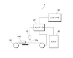
- FIG. 1 is a diagram showing an outline of a detection system 1 including a detection device 10 according to an embodiment of the present invention.
- the detection system 1 includes a detection device 10, a controller 20, a computer 30, a robot 40, and a transport device 50.
- the detection device 10 is a device that detects that the object 100 has arrived in the detection range 10a of the detection device 10 based on the measured signal value.
- the detection device 10 may be a reflective photoelectric sensor, for example.
- the detection device 10 is configured by a reflective photoelectric sensor, the amount of reflected light to be detected increases when the object 100 arrives at the detection region of the detection device 10.
- an example in which the detection device 10 is configured by a photoelectric sensor will be described in order to make the description more specific. By replacing the factor of variation and the like according to the detection principle of the sensor, it can be generalized when the detection device 10 is composed of an arbitrary sensor.
- the object 100 is an object to be detected by the detection device 10, and may be, for example, a finished product to be produced or an unfinished product such as a part. Further, in this specification, the “object” may be a part of the object 100 (an end portion of the object 100, a pattern or a defect on the object 100, etc.) in addition to the entire object 100. When the object 100 is smaller than the detection region, as in the case where the object 100 is a particle or a pin, the entire object 100 may be a detection target.
- the detection apparatus 10 may be used for an application generally called defect inspection. In that case, the detection apparatus 10 may detect that a defective portion of the object 100 has arrived in the detection range 10a. .
- the controller 20 controls the robot 40 and the transfer device 50.
- the controller 20 may be composed of, for example, a PLC (Programmable Logic Controller).
- the controller 20 detects that the object 100 has arrived based on the output from the detection device 10 and controls the robot 40.
- the computer 30 sets the detection device 10, the controller 20, and the robot 40. In addition, the computer 30 acquires the execution result of the control by the controller 20 from the controller 20. Furthermore, the computer 30 may include a learning device that generates, by machine learning, parameters used in an algorithm (learning model) for determining whether or not the object 100 has arrived at the detection range 10a by the detection device 10. Examples of the algorithm (learning model) include a neural network and a decision tree.
- the robot 40 operates and processes the object 100 according to the control by the controller 20. For example, the robot 40 may pick up the object 100 and move it to another location, or cut or assemble the object 100.
- the transport device 50 is a device that transports the object 100 in accordance with control by the controller 20.
- the transport device 50 may be, for example, a belt conveyor, and may transport the object 100 at a speed set by the controller 20.
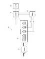
- FIG. 2 is a diagram illustrating a configuration of the detection apparatus 10 according to the present embodiment.
- the detection device 10 includes a measurement unit 11, a storage unit 12, a determination unit 13, a control unit 14, and an input / output unit 15.
- the measuring unit 11 sequentially converts a physical quantity whose value changes depending on whether or not the object 100 has arrived in the detection range 10a into a signal value.
- the measurement unit 11 may measure a physical quantity such as the amount of received light in the second period and output a signal value that is a digital value of three or more values.
- the signal value may be represented by 8 bits (256 values), for example.
- the second period may be 0.1 ms (milliseconds), for example.
- the storage unit 12 stores a predetermined number of signal values in the order measured by the measurement unit 11.
- storage part 12 deletes the oldest signal value among predetermined number of signal values, and may memorize
- FIFO first-in first-out
- the storage unit 12 includes an n-stage FIFO memory.
- the storage unit 12 has addresses of the first stage q0, the first stage q1, the second stage q2, the jth stage qj, the kth stage qk, and the nth stage qn.
- j ⁇ k ⁇ n, and n may be about 100, for example.
- the storage unit 12 deletes the signal value sn stored in the n-th stage qn, which is the final stage, in the first cycle, and stores the signal values s0, s1, s2, sj, and sk stored in each stage. Shift to the next stage, and store the newly measured signal value in the first stage q0.
- the first period may be the same as or different from the second period.
- the second period may be fixed to a value (for example, 0.1 ms) unique to the sensor constituting the measurement unit 11.
- the detection device 10 is a photoelectric sensor
- the light projecting element may perform pulse projection with a second period
- the output of the light receiving element may be A / D converted with the second period in accordance with the timing of pulse projection.
- the first period may be settable by the computer 30 via the controller 20.
- the first period needs to be determined so that the range of the signal value waveform to be processed simultaneously is stored in the storage unit 12.
- the first period may be set longer than the second period, and the second period may be 1 ms, for example.
- the average value of the signal values may be stored in the storage unit 12.
- the determination unit 13 determines whether or not the object 100 has arrived in the detection range 10a based on whether or not a plurality of predetermined signal values among the signal values stored in the FIFO memory satisfy the determination condition. To do.
- the determination unit 13 may determine whether or not the object 100 has arrived in the detection range 10a in the first period.
- the measurement part 11 may measure a signal value with the 2nd period below a 1st period. When the first period is equal to or longer than the second period, it is possible to refer to an appropriate number of signal values when determining whether or not an object has arrived in the detection range.
- the determination condition such as which signal value stored in which address of the storage unit 12 is used for determination by the determination unit 13 and what determination logic is used for determination may be set from the computer 30 via the controller 20. . Note that the determination condition may be set in the manufacturing stage of the detection apparatus 10.
- the determination result by the determination unit 13 may be a binary value corresponding to whether the object 100 has arrived in the detection range 10a or whether the object 100 has not arrived in the detection range 10a, but the determination result has three or more values. It may be represented by For example, when the determination result is ternary, in addition to the state in which the object 100 has arrived and the state in which the object 100 has not arrived, a state that has the possibility of arrival but has low accuracy may be added as the third state.
- the presence or absence of the object 100 in the detection range 10a is detected by comparing a signal value at a certain time point with a threshold value, and whether or not the object 100 has arrived due to a change in the detection result. Rather than determining whether or not the object 100 has arrived in the detection range 10a based on whether or not a change in a predetermined number of signal values stored in the storage unit 12 satisfies the determination condition. Thus, the arrival of the object 100 can be detected without burdening the user who sets the threshold value according to the use situation.
- the control unit 14 controls the operation of the entire detection apparatus 10.
- the control unit 14 can be configured as, for example, a computer including a microprocessor, a memory, a detection device control program stored in the memory, and the like.
- the detection device control program may be provided by being stored in a computer-readable storage medium, or may be provided from the computer 30 of the detection system 1 via a communication path.
- the control unit 14 may make necessary settings for the first cycle, the second cycle, and the determination condition for the determination unit 13 to perform the determination according to the setting by the computer 30.
- the microprocessor of the control unit 14 functions as the determination unit 13 by executing a detection device control program including a process for determining whether or not the object 100 has arrived in the detection range 10a by the detection device 10. Also good.
- the control unit 14 may realize a FIFO memory by controlling the memory included in the control unit 14 according to the detection device control program, and may replace the storage unit 12 with the memory included in the control unit 14. In this case, the shift of the signal value to the subsequent stage of the FIFO memory can be performed by updating the access location on the memory, not the physical shift of the stored data.
- the storage unit 12 may be realized by dedicated hardware.
- control unit 14 holds an external output state indicating that the object 100 has arrived until a certain period thereafter or until it is reset from the outside. You may do it.
- the input / output unit 15 outputs at least a signal corresponding to the arrival of the object 100 to the outside.
- the input / output unit 15 may output a binary voltage signal or current signal corresponding to the arrival and non-arrival of the object 100 through a single signal line. Note that when the detection apparatus 10 does not accept setting by communication from the outside, the input / output unit 15 may have only the output unit regardless of the name of the input / output unit 15.
- the input / output unit 15 may include a network interface, receive setting information, and output a determination result by the determination unit 13.
- the input / output unit 15 may accept an input of a determination condition used for determination by the determination unit 13. Thereby, the determination conditions for determining that the target object 100 has arrived in the detection range 10a can be adjusted, and the arrival of the target object 100 can be detected based on the user's desired conditions.
- the detection device 10 may further include an operation key and an indicator lamp not shown.
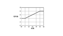
- FIG. 3a is a graph showing an example of signal values measured by the detection apparatus 10 according to the present embodiment.
- time is shown on the horizontal axis
- signal values are shown on the vertical axis
- changes in signal values over time are shown by graphs.
- the intervals of t0, t1, t2,... T6 shown on the horizontal axis are the first period, and may be, for example, 1 ms intervals.
- the signal value may be any electrical signal, but may be a voltage signal, for example, in which case the unit is volts.
- the signal value is shown as a waveform that does not include a polygonal line noise.
- the waveform actually obtained may be a waveform in which noise is superimposed,
- the rising part and the falling part may be curved.
- FIG. 3 b is a diagram illustrating an example of a predetermined number of signal values stored in the detection apparatus 10 according to the present embodiment.
- the horizontal axis indicates the FIFO stage
- the vertical axis indicates the signal value
- the signal value stored in the storage unit 12 is indicated by a graph.
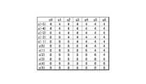
- the storage unit 12 stores the seven signal values in the order measured by the measurement unit 11. That is, the signal value “8” measured at time t6 is stored in the first stage q0, and the signal value “8” measured at time t5 is stored in the first stage q1. The same applies to the second stage q2 to the fifth stage q5, and the signal value “4” measured at time t0 is stored in the sixth stage q6.
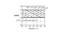
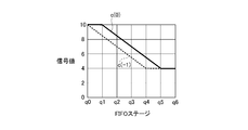
- FIG. 4a is a graph showing an example of a predetermined number of signal values stored in the detection apparatus 10 according to the present embodiment in the first case.
- the horizontal axis indicates the FIFO stage
- the vertical axis indicates the signal value
- the signal value stored in the storage unit 12 is indicated by a graph.
- FIG. 4B is a diagram illustrating an example of a predetermined number of signal values stored in the detection apparatus 10 according to the present embodiment in the first case.
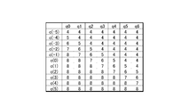
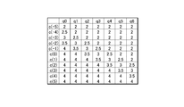
- the signal values shown in FIG. Hereinafter, the notation “c (n)” (where n is an integer) indicates the nth cycle of FIFO memory update. Which cycle is selected as the 0th cycle is arbitrary.
- the signal values stored in the FIFO memory in the nth period are collectively referred to as “signal value c (n)”.
- the signal value c ( ⁇ 5) measured and stored until the object 100 does not arrive in the detection range 10a is indicated by a solid line, and then the oldest signal value is deleted and newly A signal value c ( ⁇ 4) in which the measured signal value is stored is indicated by a broken line.
- the signal value c ( ⁇ 5) is “4” for the first stage q0 to the sixth stage q6, indicating that the object 100 has not arrived in the detection range 10a.
- the detection apparatus 10 deletes the oldest signal value stored in the sixth stage q6, shifts the signal value stored in the first stage q0 to the fifth stage q5 by one stage, and newly measures the signal value “ 5 ”is stored in the first stage q0.
- the signal value c ( ⁇ 4) is “5” for the first stage q0 and “4” for the first stage q1 to the sixth stage q6, indicating that the object 100 has entered the detection range 10a.
- the oldest signal value “4” stored in the sixth stage q6 is deleted, and the newly measured signal value “6” is stored in the first stage q0.
- the signal value c (-3) is indicated by a one-dot chain line.
- the oldest signal value “4” stored in the sixth stage q6 is deleted, and the newly measured signal value “7” is stored in the first stage q0.
- the value c ( ⁇ 2) is indicated by a two-dot chain line.
- the oldest signal value “4” stored in the sixth stage q6 is deleted, and the newly measured signal value “8” is stored in the first stage q0.
- the value c (-1) is indicated by a dotted line.
- the oldest signal value “4” stored in the sixth stage q6 is deleted, and the newly measured signal value “8” is stored in the first stage q0.
- the value c (0) is indicated by a solid line. Further, after storing the signal value c (0), the oldest signal value “4” stored in the sixth stage q6 is deleted, and the newly measured signal value “8” is stored in the first stage q0.
- the determination unit 13 measures the signal value by the measurement unit 11 and whether or not a predetermined number of signal values satisfy the determination condition. Whether or not the object 100 has arrived in the detection range 10a is determined.
- the determination condition is that the signal value acquired at the first time point is substantially equal to the signal value acquired at the second time point after the first time point, and the signal acquired at the second time point.
- the signal value acquired at the third time point after the second time point is larger than the value, and the absolute value of the difference may be larger than the predetermined value.
- this condition is referred to as a first determination condition.
- the first determination condition is an example of a condition indicating that a predetermined number of signal values include a rising waveform.
- the signal value pattern sequentially stored in the FIFO memory has a predetermined rising waveform, it is determined that the object 100 has arrived in the detection range 10a.
- the signal value acquired at the first time point in the first determination condition may be the signal value stored in the sixth stage q6, and the signal value acquired at the second time point is the fifth stage.
- the signal value stored in q5 may be the signal value acquired at the third time point may be the signal value stored in the fourth stage q4. That is, the first determination condition is that the signal value stored in the sixth stage q6 is substantially equal to the signal value stored in the fifth stage q5, and that the signal value stored in the fifth stage q5 is May include that the signal value stored in the fourth stage q4 is larger and the absolute value of the difference is larger than a predetermined value.
- the difference between the two signal values being larger than the predetermined value means that the difference between the two signal values is different beyond the range of the influence of noise.
- the signal value stored in the fifth stage q5 is greater than 0.2, the signal value stored in the fifth stage q5 is It may be determined that the signal value stored in the fourth stage q4 is larger and the absolute value of the difference is larger than a predetermined value.
- the condition is that the signal value stored in the sixth stage q6 and the signal value stored in the fifth stage q5 are substantially equal.
- Signal values satisfying the conditions are signal values c ( ⁇ 5) to c (0).
- the signal value that satisfies the condition that the signal value stored in the fourth stage q4 is larger than the signal value stored in the fifth stage q5 and the absolute value of the difference is larger than a predetermined value The signal values are c (0) to c (3). Therefore, in this example, the signal value that satisfies the first determination condition is only the signal value c (0). Therefore, the determination unit 13 determines that the object 100 has arrived in the detection range 10a in the cycle in which the signal value c (0) is stored.
- the signal value stored in the sixth stage q6 and the signal stored in the fifth stage q5 are stored.
- the difference from the signal value is within a range of ⁇ 0.2
- the signal value stored in the fourth stage q4 is smaller than the signal value stored in the fifth stage q5, and the absolute value of the difference Is determined to be greater than 0.2.
- condition for detecting the rising portion of the waveform may include a condition that three or more signal values are monotonically increasing (monotonically decreasing when the falling portion of the waveform is detected). The same applies to the second to fifth cases described below.
- the determination condition is that the signal value acquired at the first time point is substantially equal to the signal value acquired at the second time point after the first time point, and acquired at the third time point after the second time point.
- the signal value acquired at the fourth time point after the third time point is substantially equal to the signal value acquired at the first time point and the signal value acquired at the second time point. Any one of the signal value acquired at the third time point and the signal value acquired at the fourth time point is larger than either, and the absolute value of the difference is larger than the predetermined value. Good.
- this condition is referred to as a second determination condition.
- the second determination condition is an example of a condition indicating that a predetermined number of signal values include a rising waveform. In this example, when the signal value pattern sequentially stored in the FIFO memory has a predetermined rising waveform, it is determined that the object 100 has arrived in the detection range 10a.
- the signal value acquired at the first time point in the second determination condition may be the signal value stored in the sixth stage q6, and the signal value acquired at the second time point is the fifth stage.
- the signal value acquired at the third time point may be the signal value stored at q5
- the signal value stored at the first stage q1 may be the signal value acquired at the fourth time point. It may be the signal value stored in q0.
- the signal values that satisfy the condition that the absolute value of the difference is larger than the predetermined value are signal values c ( ⁇ 4) to c (4). Therefore, in this example, the signal value that satisfies the second determination condition is only the signal value c (0). Therefore, the determination unit 13 determines that the object 100 has arrived in the detection range 10a in the cycle in which the signal value c (0) is stored.
- the signal value stored in the sixth stage q6 and the signal stored in the fifth stage q5 are stored.
- the difference between the signal value is within a range of ⁇ 0.2
- the difference between the signal value stored in the first stage q1 and the signal value stored in the first stage q0 is within a range of ⁇ 0.2.
- the determination condition may be that the difference is smaller and the absolute value of the difference is greater than 0.2. The same applies to the second to fifth cases described below.
- signal values acquired at three or more time points are used to determine whether or not the signal values are substantially equal, and the signal values are substantially substantially different from other signal values. Even if unequal signal values occur, such signal values may be excluded. For example, it may be determined whether or not the signal value is an outlier, and the outlier may be excluded. Thereby, malfunction due to noise can be reduced.
- the detection apparatus 10 may receive an input of the first determination condition or the second determination condition through the input / output unit 15.
- the data of the signal value actually measured is sent from the detection apparatus 10 to the computer 30, and it is used to confirm whether the determination condition prototyped using the data works well on the actually measured waveform.
- the simulation may be performed by the computer 30.
- the determination condition creation procedure performed by the user may be programmed and the determination condition creation using the computer 30 semi-automated.
- the determination condition thus created may be set in the detection device 10 from the computer 30 via the controller 20 or at the manufacturing stage of the detection device 10.
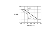
- FIG. 5a is a diagram illustrating an example of a predetermined number of signal values stored in the detection device 10 according to the present embodiment in a graph in the second case.
- the horizontal axis indicates the FIFO stage
- the vertical axis indicates the signal value
- the signal value stored in the storage unit 12 is indicated by a graph.
- the reflectance of the object 100 is larger than that in the first case, and the signal value measured by the measurement unit 11 when the object 100 arrives in the detection range 10a is higher than in the case of the first case.
- a large example is shown. Specifically, the signal value measured by the measurement unit 11 when the object 100 arrives in the detection range 10a in the second case is 1.25 times that in the first case.
- FIG. 5a after storing the signal value c ( ⁇ 2), the oldest signal value “4” stored in the sixth stage q6 is deleted, and the newly measured signal value “10” is stored in the first stage q0.
- the obtained signal value c ( ⁇ 1) is indicated by a broken line.
- the oldest signal value “4” stored in the sixth stage q6 is deleted, and the newly measured signal value “10” is stored in the first stage q0.
- the value c (0) is indicated by a solid line.
- the determination unit 13 measures the signal value by the measurement unit 11 while measuring the predetermined number. Whether or not the object 100 has arrived in the detection range 10a can be determined based on whether or not the signal value satisfies the determination condition.
- the determination condition may be at least one of the first determination condition and the second determination condition.
- the condition is that the signal value stored in the sixth stage q6 and the signal value stored in the fifth stage q5 are substantially equal.
- Signal values satisfying the conditions are signal values c ( ⁇ 5) to c (0).
- the signal value that satisfies the condition that the signal value stored in the fourth stage q4 is larger than the signal value stored in the fifth stage q5 and the absolute value of the difference is larger than a predetermined value The signal values are c (0) to c (3). Therefore, in this example, the signal value that satisfies the first determination condition is only the signal value c (0). Therefore, the determination unit 13 determines that the object 100 has arrived in the detection range 10a in the cycle in which the signal value c (0) is stored.
- the signal value stored in the sixth stage q6 is substantially equal to the signal value stored in the fifth stage q5.
- Signal values satisfying the condition are signal values c ( ⁇ 5) to c (0).
- the signal values satisfying the condition that the signal value stored in the first stage q1 and the signal value stored in the first stage q0 are substantially equal are signal values c (0) to c (5). Further, any of the signal value stored in the first stage q1 and the signal value stored in the first stage q0 is greater than either the signal value stored in the sixth stage q6 or the signal value stored in the fifth stage q5.
- the signal values that satisfy the condition that the absolute value of the difference is larger than the predetermined value are signal values c ( ⁇ 4) to c (4). Therefore, in this example, the signal value that satisfies the second determination condition is only the signal value c (0). Therefore, the determination unit 13 determines that the object 100 has arrived in the detection range 10a in the cycle in which the signal value c (0) is stored.
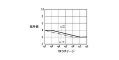
- FIG. 6 a is a graph showing an example of a predetermined number of signal values stored in the detection apparatus 10 according to the present embodiment in the third case.
- the horizontal axis indicates the FIFO stage
- the vertical axis indicates the signal value
- the signal value stored in the storage unit 12 is indicated by a graph.
- FIG. 6 b is a diagram illustrating an example of a predetermined number of signal values stored in the detection apparatus 10 according to the present embodiment in the third case. In the same figure, the signal values shown in FIG.
- the background reflectance is small compared to the first case, and the signal value measured by the measurement unit 11 when the object 100 does not arrive in the detection range 10a is smaller than that in the first case.
- the signal value measured by the measurement unit 11 when the object 100 does not arrive in the detection range 10a in the third case is 0.5 times that in the first case.
- FIG. 6a after storing the signal value c ( ⁇ 2), the oldest signal value “2” stored in the sixth stage q6 is deleted, and the newly measured signal value “8” is stored in the first stage q0.
- the obtained signal value c ( ⁇ 1) is indicated by a broken line.
- the oldest signal value “2” stored in the sixth stage q6 is deleted, and the newly measured signal value “8” is stored in the first stage q0.
- the value c (0) is indicated by a solid line.
- the determination unit 13 measures the signal value by the measurement unit 11 and the predetermined number of signal values. Whether or not the object 100 has arrived in the detection range 10a can be determined based on whether or not the determination condition is satisfied.
- the determination condition may be at least one of the first determination condition and the second determination condition.
- the condition is that the signal value stored in the sixth stage q6 and the signal value stored in the fifth stage q5 are substantially equal.
- Signal values satisfying the conditions are signal values c ( ⁇ 5) to c (0).
- the signal value that satisfies the condition that the signal value stored in the fourth stage q4 is larger than the signal value stored in the fifth stage q5 and the absolute value of the difference is larger than a predetermined value The signal values are c (0) to c (3). Therefore, in this example, the signal value that satisfies the first determination condition is only the signal value c (0). Therefore, the determination unit 13 determines that the object 100 has arrived in the detection range 10a in the cycle in which the signal value c (0) is stored.
- the signal value stored in the sixth stage q6 is substantially equal to the signal value stored in the fifth stage q5.
- Signal values satisfying the condition are signal values c ( ⁇ 5) to c (0).
- the signal values satisfying the condition that the signal value stored in the first stage q1 and the signal value stored in the first stage q0 are substantially equal are signal values c (0) to c (5). Further, any of the signal value stored in the first stage q1 and the signal value stored in the first stage q0 is greater than either the signal value stored in the sixth stage q6 or the signal value stored in the fifth stage q5.
- the signal values that satisfy the condition that the absolute value of the difference is larger than the predetermined value are signal values c ( ⁇ 4) to c (4). Therefore, in this example, the signal value that satisfies the second determination condition is only the signal value c (0). Therefore, the determination unit 13 determines that the object 100 has arrived in the detection range 10a in the cycle in which the signal value c (0) is stored.
- FIG. 7a is a graph showing an example of a predetermined number of signal values stored in the detection apparatus 10 according to the present embodiment in the fourth case.
- the horizontal axis indicates the FIFO stage
- the vertical axis indicates the signal value
- the signal value stored in the storage unit 12 is indicated by a graph.
- FIG. 7 b is a diagram illustrating an example of a predetermined number of signal values stored in the detection device 10 according to the present embodiment in the fourth case. In the same figure, the signal values shown in FIG.
- the fourth case shows an example in which the amount of light emitted from the measuring unit 11 is smaller than that in the first case, and the signal value measured by the measuring unit 11 is smaller than that in the first case.
- the signal value measured by the measurement unit 11 when the object 100 arrives in the detection range 10a in the fourth case is 0.5 times that in the first case, and the target value is in the detection range 10a.
- the signal value measured by the measurement unit 11 when the object 100 has not arrived is also 0.5 times that in the first case.
- FIG. 7a after storing the signal value c ( ⁇ 2), the oldest signal value “2” stored in the sixth stage q6 is deleted, and the newly measured signal value “4” is stored in the first stage q0.
- the obtained signal value c ( ⁇ 1) is indicated by a broken line. Further, after storing the signal value c ( ⁇ 1), the oldest signal value “2” stored in the sixth stage q6 is deleted, and the newly measured signal value “4” is stored in the first stage q0. The value c (0) is indicated by a solid line.
- the determination unit 13 measures the signal value by the measurement unit 11 while the predetermined number. Whether or not the object 100 has arrived in the detection range 10a can be determined based on whether or not the signal value satisfies the determination condition.
- the determination condition may be at least one of the first determination condition and the second determination condition.
- the condition is that the signal value stored in the sixth stage q6 and the signal value stored in the fifth stage q5 are substantially equal.
- Signal values satisfying the conditions are signal values c ( ⁇ 5) to c (0).
- the signal value that satisfies the condition that the signal value stored in the fourth stage q4 is larger than the signal value stored in the fifth stage q5 and the absolute value of the difference is larger than a predetermined value The signal values are c (0) to c (3). Therefore, in this example, the signal value that satisfies the first determination condition is only the signal value c (0). Therefore, the determination unit 13 determines that the object 100 has arrived in the detection range 10a in the cycle in which the signal value c (0) is stored.
- the signal value stored in the sixth stage q6 is substantially equal to the signal value stored in the fifth stage q5.
- Signal values satisfying the condition are signal values c ( ⁇ 5) to c (0).
- the signal values satisfying the condition that the signal value stored in the first stage q1 and the signal value stored in the first stage q0 are substantially equal are signal values c (0) to c (5). Further, any of the signal value stored in the first stage q1 and the signal value stored in the first stage q0 is greater than either the signal value stored in the sixth stage q6 or the signal value stored in the fifth stage q5.
- the signal values that satisfy the condition that the absolute value of the difference is larger than the predetermined value are signal values c ( ⁇ 4) to c (4). Therefore, in this example, the signal value that satisfies the second determination condition is only the signal value c (0). Therefore, the determination unit 13 determines that the object 100 has arrived in the detection range 10a in the cycle in which the signal value c (0) is stored.
- FIG. 8a is a graph showing an example of a predetermined number of signal values stored in the detection apparatus 10 according to the present embodiment in the fifth case.
- the horizontal axis indicates the FIFO stage
- the vertical axis indicates the signal value
- the signal value stored in the storage unit 12 is indicated by a graph.
- FIG. 8 b is a diagram illustrating an example of a predetermined number of signal values stored in the detection apparatus 10 according to the present embodiment in the fifth case. In the same figure, the signal values shown in FIG.
- the fifth case shows an example in which the object 100 moves faster than the first case.
- the signal value measured by the measurement unit 11 when the object 100 arrives in the detection range 10a in the fifth case is the same size as in the first case, but the signal value changes. fast.
- the signal value c ( ⁇ 2) after storing the signal value c ( ⁇ 2), the oldest signal value “4” stored in the sixth stage q6 is deleted, and the newly measured signal value “8” is stored in the first stage q0.
- the obtained signal value c ( ⁇ 1) is indicated by a broken line.
- the oldest signal value “4” stored in the sixth stage q6 is deleted, and the newly measured signal value “8” is stored in the first stage q0.
- the value c (0) is indicated by a solid line.
- the determination unit 13 measures the signal value by the measurement unit 11, Based on whether or not the predetermined number of signal values satisfy the determination condition, it can be determined whether or not the object 100 has arrived in the detection range 10a.
- the determination condition may be at least one of the first determination condition and the second determination condition.
- the condition is that the signal value stored in the sixth stage q6 and the signal value stored in the fifth stage q5 are substantially equal.
- Signal values satisfying the conditions are signal values c ( ⁇ 5) to c (1).
- the signal value stored in the sixth stage q6 is substantially equal to the signal value stored in the fifth stage q5.
- Signal values satisfying the condition are signal values c ( ⁇ 5) to c (1).
- the signal values satisfying the condition that the signal value stored in the first stage q1 and the signal value stored in the first stage q0 are substantially equal are signal values c ( ⁇ 1) to c (5). .
- any of the signal value stored in the first stage q1 and the signal value stored in the first stage q0 is greater than either the signal value stored in the sixth stage q6 or the signal value stored in the fifth stage q5.
- the signal values that satisfy the condition that the absolute value of the difference is larger than the predetermined value are signal values c ( ⁇ 3) to c (3). Therefore, in this example, the signal values that satisfy the second determination condition are the signal values c ( ⁇ 1), c (0), and c (1). Therefore, the determination unit 13 determines that the object 100 has arrived in the detection range 10a during the period in which the signal values c ( ⁇ 1), c (0), and c (1) are stored.
- the signal value fluctuates depending on the usage situation, but nevertheless, the rising or falling of the signal value can be detected stably, and the threshold value is set.
- the arrival of an object can be detected without the burden on the user set according to the usage situation.
- the first judgment condition is assumed that the midpoint of the rising portion of the waveform of the signal value c (0) is stored in the third stage q3 of the FIFO stage for easy understanding.
- both the second determination condition and the second determination condition are examples in which the determination condition is satisfied in the vicinity of the signal value c (0).
- the signal value satisfying the determination condition may not be stored in the middle stage of the FIFO stage at the midpoint of the rising edge of the waveform.
- the signal values stored in the fourth stage q4 to the sixth stage q6 or the third stage q3 to the sixth stage q6 of the FIFO stage are used for the determination, and stored in the first stage q0 to the second stage q2.
- the signal value is not used for determination.
- the first determination condition is corrected, and the determination condition is corrected to use the first stage q0 to the third stage q3 so that the determination condition is satisfied when the midpoint of the rising portion of the waveform is stored in the first stage q1. Then, the rising edge can be detected three cycles earlier with respect to the first period.
- the first determination condition is that the signal value stored in the third stage q3 is substantially equal to the signal value stored in the second stage q2, and is stored in the second stage q2.
- the condition may be that the signal value stored in the first stage q1 is larger than the signal value and the absolute value of the difference is larger than a predetermined value.
- the signal value stored in the first stage q1 is substantially equal to the signal value stored in the first stage q0 and the signal value stored in the first stage q0 is greater than the signal value stored in the first stage q1.
- a condition that the value is larger and at least one of the absolute value of the difference is larger than a predetermined value may be added.
- the signal value that satisfies this determination condition is the signal value c ( ⁇ 3).
- the signal value c ( ⁇ 3).
- Whether or not the object 100 has arrived in the detection range 10a is determined by the execution of a learned model specified by a parameter generated by machine learning, and a waveform composed of a plurality of time-series signal values is machine learning data. It can also be determined as a determination condition that a positive result can be obtained for the features common to the features of the plurality of set reference waveforms.
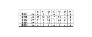
- FIG. 9 is a diagram illustrating examples of signal values constituting a rising waveform that may be measured in various states of the detection device 10 and the conveyance device 50 by the detection device 10 according to the present embodiment.
- the same signal value as the signal value c (0) stored in each case from the first case to the fifth case is shown as a signal value constituting a rising waveform that may be measured.
- the waveform composed of the signal values shown in the figure is an example of a reference waveform prepared as a machine learning data set.
- the falling waveform is set as a reference waveform.
- a rising waveform or a falling waveform that may be measured for various types of objects 100 by the detection apparatus 10 may be used as the reference waveform.
- the determination unit 13 measures the signal value by the measurement unit 11, and the object 100 has arrived in the detection range 10a based on whether or not a predetermined number of signal values stored in the storage unit 12 satisfy the determination condition. It is determined whether or not. As a result, even if the signal value fluctuates according to the use situation, the rising waveform that may be measured when the object 100 arrives in the detection range 10a, that is, a machine learning data set is obtained. It is possible to determine whether or not the detection object 100 has arrived based on whether or not the characteristics common to the characteristics of the plurality of reference waveforms are included, and eliminate the burden on the user of setting the threshold according to the usage situation. Thus, the arrival of the object 100 can be detected.
- the plurality of signal values constituting the reference waveform are the same signal values as the signal value c (0) stored in the first to fifth cases.
- the signal values constituting the reference waveform do not have to be actually measured signal values, but may be signal values generated by a person or by some algorithm.
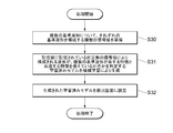
- FIG. 10 is a flowchart of a learned model setting method executed by the detection apparatus 10 according to the present embodiment.
- the learned model setting method is a method in which a learned model is generated by a learning device, and the learned model is set (implemented) in the detection device 10.
- a plurality of signal values constituting each reference waveform are prepared (S30). For example, signal values as shown in FIG. 9 are prepared.
- a learned model is generated by machine learning (S31).
- the learned model may be an arbitrary model, but may be a neural network or a decision tree, for example.
- the algorithm for generating the parameters of the learned model by machine learning may be arbitrary.
- the parameters are generated by the error back propagation method using a momentum method, Adam, or the like.
- it may be CART (Classification and Regression Trees) or ID3 (Iterative and Dichotomiser 3).
- the generated learned model is set (implemented) in the detection apparatus 10 (S32). This completes the setting method.
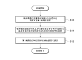
- FIG. 11 is a flowchart showing the setting method for setting the detection apparatus 10 according to the present embodiment more comprehensively including the setting method of FIG.
- the 1st period which determines whether the target object 100 arrived at the detection range 10a is determined (S10).
- the first period is based on the time required for the rise or fall of the signal value waveform so that the signal value necessary for determining whether or not the object 100 has arrived in the detection range 10a is stored in the storage unit 12. May be determined.
- the determination condition may be, for example, the first determination condition described above, the second determination condition, or a predetermined result obtained by executing the learned model.
- the determination condition may include designation of a plurality of time points used for determination among the acquisition time points of the predetermined number of signal values stored in the storage unit 12. For example, three or more FIFO stages storing signal values used for determination among a predetermined number of signal values stored in the storage unit 12 may be designated as time points used for determination.
- Determination of determination conditions and setting to the detection device 10 are preferably performed by the supplier of the detection device 10.
- the supplier of the detection device 10 refers to a person other than the final user of the detection device 10 such as a manufacturer, a seller, or a service provider related to the introduction of the detection device 10. Since the determination condition is a condition for determining whether the waveform of the signal value corresponds to the signal value constituting the rising waveform or the falling waveform, the type of the object 100 in the final user of the detection apparatus 10 Even a supplier who does not know the installation state of the detection device 10 can determine the determination condition.
- FIG. 12 is a flowchart of a detection method executed by the detection apparatus 10 according to this embodiment.
- the detection method is a method for determining whether or not the object 100 has arrived at the detection range 10 a by the determination unit 13.
- the detection apparatus 10 determines whether or not it is a cycle for determining whether the signal value satisfies the determination condition (S22).
- the determination unit 13 determines whether or not the signal values of a plurality of predetermined ranks among the signal values stored in the storage unit 12 satisfy the determination condition. Determine (S23).
- the determination condition may be, for example, the first determination condition described above, the second determination condition, or a predetermined result obtained by executing the learned model. If the predetermined signal values stored in the storage unit 12 satisfy the determination condition (S23: YES), the detection device 10 determines that the object 100 has arrived in the detection range 10a, and the determination The result is output by the input / output unit 15 (S24).
- the detection apparatus 10 When the output of the determination result is finished, when it is not a cycle for determining whether or not the signal value satisfies the determination condition (S22: NO), and when the predetermined signal values do not satisfy the determination condition (S23: NO), The detection apparatus 10 returns to the process of waiting for the update timing of the storage unit 12 in the first period (S20). The above processing may be repeated continuously.
- the object (100) has arrived at the detection range (10a) based on a signal value corresponding to a physical quantity whose value changes depending on whether the object (100) has arrived at the detection range (10a).
- a detection device (10) for detecting A measurement unit (11) for sequentially converting the physical quantity into the signal value;
- a storage area for storing a predetermined number of the signal values in the order obtained from the measurement unit (11) is provided, and the predetermined number of the stored signal values is stored in the measurement unit (11) in a first period.
- a determination unit that determines whether or not the object (100) has arrived in the detection range (10a) based on whether or not a determination condition for determining whether or not the signal value is included is satisfied.
- a detection device (10) comprising:
Landscapes
- General Physics & Mathematics (AREA)
- Physics & Mathematics (AREA)
- Life Sciences & Earth Sciences (AREA)
- Immunology (AREA)
- Analytical Chemistry (AREA)
- Biochemistry (AREA)
- General Health & Medical Sciences (AREA)
- Chemical & Material Sciences (AREA)
- Health & Medical Sciences (AREA)
- Pathology (AREA)
- General Life Sciences & Earth Sciences (AREA)
- Geophysics (AREA)
- Geophysics And Detection Of Objects (AREA)
- Investigating Materials By The Use Of Optical Means Adapted For Particular Applications (AREA)
- Measuring Pulse, Heart Rate, Blood Pressure Or Blood Flow (AREA)
- Eye Examination Apparatus (AREA)
Abstract
閾値を使用状況に応じて設定するユーザの負担を無くして対象物の到来を検出することができる検出装置及び検出プログラムを提供する。検出装置10は、検出範囲10aに対象物100が到来したか否かに応じて値が変化する物理量に対応する信号値に基づいて、検出範囲に対象物が到来したことを検出する検出装置であって、物理量を逐次信号値に変換する測定部11と、所定数の信号値を測定部から取得した順に順序付けて記憶するための記憶領域を備え、第1周期で、記憶している所定数の信号値を測定部から新たに取得した信号値により更新する記憶部12と、更新を1回または複数回行う毎に一度の頻度で、記憶部に記憶されている信号値のうちの所定の複数の順位の信号値が立ち上がり波形又は立ち下がり波形を構成する信号値に該当するか否かを判定するための判定条件を満たすか否かに基づいて、検出範囲に対象物が到来したか否かを判定する判定部13と、を備える。
Description
本発明は、対象物の到来を検出する検出装置に関する。
従来、対象物の到来を検出する検出方法として、対象物に光を照射して、対象物を透過する光を検出したり、対象物による光の遮蔽を検出したり、対象物により反射した光を検出したりする方法が用いられている。また、他の検出方法として、対象物に超音波を当て、超音波の反射を用いる方法も知られている。これら既存の検出方法では、受光量、超音波受信強度のような物理量に対応する信号値の大きさを閾値と比較して対象物の有無に対応する出力信号を得、出力信号の変化によって対象物の到来を判定することがある。ここで、物理量に対応する信号値の大きさは、対象物の種類及び対象物と検出装置との位置関係によって変動するため、検出装置を設置した後にユーザが閾値を設定しなければならない場合が多い。
ユーザによる閾値の設定について、例えば下記特許文献1には、ワークを検出エリアに配置した状態でSETキーを押し、ワークを検出エリアから取り除いた状態でSETキーを再び押し、各キーの操作に応じて測定された2種類の受光量を用いて閾値を設定することが記載されている。
また、下記特許文献2に記載の光電センサでは、環境要因に追従し、光量の判定基準となる閾値を自動調整するにあたり、受光量現在値データとして、光電センサが入光判定をしてから一定期間の受光量変動プロファイルを測定している。そして、受光量が最大値において一定になる期間があるか否かを判定して、一定になる期間がある場合に測定した受光量現在値データを有効なものとしている。
特許文献1及び2に記載のように、従来、検出装置の閾値を使用状況に応じて設定することを前提として、ユーザによる閾値設定を容易にしたり、当初設定した閾値を経時的に再調整する負担を軽減したりする、という方向で開発が行われてきた。
しかしながら、従来の技術では、検出装置の閾値を使用状況に応じて設定するユーザの負担は取り除くことができなかった。
そこで、本発明は、閾値を使用状況に応じて設定するユーザの負担を無くして対象物の到来を検出することができる検出装置を提供する。
対象物の到来を検出する場合に、実際の使用場面で求められるのは、対象物が到来した時点で対象物が到来したことを報知する機能である。一方で、現時点における対象物の有無自体を検出することは、求められることが少ない。すなわち、検出装置の出力値は現時点における対象物の有無に対応しているとしても、ユーザは、短い周期で更新される出力値が時系列に得られることを前提として、出力値が対象物無しに対応する値から対象物有りに対応する値に変化する事象またはその逆に変化する事象をトリガにして機械に所定の動作をさせる場合が多い。そうではなく、たとえば機械の制御システムから現時点における対象物の有無に対応する出力値を要求し、それに応答して得られた単発的な出力値にしたがい機械を動作させることは少ない。従って、対象物の到来に対応する信号値の急な変化、すなわち信号値波形の立ち上がり又は立ち下がりが発生したことを検出すれば、閾値を用いずに実用上の要求を満たすことができる。
そこで、本開示の一態様に係る検出装置は、検出範囲に対象物が到来したか否かに応じて値が変化する物理量に対応する信号値に基づいて、検出範囲に対象物が到来したことを検出する検出装置であって、物理量を逐次信号値に変換する測定部と、所定数の信号値を測定部から取得した順に順序付けて記憶するための記憶領域を備え、第1周期で、記憶している所定数の信号値を測定部から新たに取得した信号値により更新する記憶部と、更新を1回または複数回行う毎に一度の頻度で、記憶部に記憶されている信号値のうちの所定の複数の順位の信号値が立ち上がり波形又は立ち下がり波形を構成する信号値に該当するか否かを判定するための判定条件を満たすか否かに基づいて、検出範囲に対象物が到来したか否かを判定する判定部と、を備える。
この態様によれば、ある時点における信号値と閾値とを比較して検出範囲における対象物の有無を検出し、検出結果の変化によって対象物が到来したか否かを判定するのではなく、記憶部に記憶された所定数の信号値により構成される波形が所定の条件を満たすか否かに基づいて、検出範囲に対象物が到来したか否かを判定することができる。このため、閾値を使用状況に応じて設定するユーザの負担を無くして対象物の到来を検出することができる。さらに、この判定条件は、信号値の波形が立ち上がり波形又は立ち下がり波形に該当するか否かを判定するための条件であるから、対象物の種類や検出装置の設置状態が異なっていても共通の判定条件を適用できる場合が多い。この点でも、検出実行の準備をする段階でのユーザの負担は軽減される。
上記態様において、記憶部は、所定数の信号値のうち、最も古い信号値を削除し、新たに取得した信号値を記憶してもよい。
この態様によれば、記憶部をFIFOメモリとすることで、ハードウェアの規模を小さく抑えつつ、高速に読み書き可能とすることができる。
上記態様において、第1周期は、変更可能であってもよい。
この態様によれば、第1周期を適切に設定することにより、検出範囲に対象物が到来したか否かを判定する際に適切な時間長にわたる信号値を参照することができる。
上記態様において、判定条件は、第1時点において取得された信号値と、第1時点より後の第2時点において取得された信号値とが実質的に等しいことと、第2時点において取得された信号値と、第2時点より後の第3時点において取得された信号値との差の絶対値が所定の値よりも大きいことと、を含んでもよい。
この態様によれば、使用状況に応じて信号値が変動する場合であっても、信号値の立ち上がり又は立下りを安定的に検出することができ、閾値を使用状況に応じて設定するユーザの負担を無くして対象物の到来を検出することができる。
上記態様において、判定条件は、第1時点において取得された信号値と、第1時点より後の第2時点において取得された信号値とが実質的に等しいことと、第2時点より後の第3時点において取得された信号値と、第3時点より後の第4時点において取得された信号値とが実質的に等しいことと、第1時点において取得された信号値及び第2時点において取得された信号値のいずれかと、第3時点において取得された信号値及び第4時点において取得された信号値のいずれかとの差の絶対値が、所定の値よりも大きいことと、を含んでよい。
この態様によれば、使用状況に応じて信号値が変動する場合であっても、信号値の立ち上がり又は立下りを安定的に検出することができ、閾値を使用状況に応じて設定するユーザの負担を無くして対象物の到来を検出することができる。
上記態様において、判定条件は、機械学習により生成されたパラメータにより特定される学習済みモデルの実行により、時系列の複数の信号により構成される波形が機械学習用データセットとされた複数の基準波形が有する特徴と共通する特徴を備えていることについて肯定的な結果が得られることであってもよい。
この態様によれば、現在の信号値により構成される波形が、複数の基準波形が有する特徴と共通する特徴を備えているかを学習済みモデルの実行により判定することで、検出装置の処理負荷を軽減しつつ、検出範囲に対象物が到来したか否かを高精度で判定することができる。
上記態様において、判定条件の入力を受け付ける入力部をさらに備えてもよい。
この態様によれば、検出範囲に対象物が到来したと判定するための所定の条件を調整することができ、ユーザの所望の条件により対象物の到来を検出することができる。
本発明によれば、閾値を使用状況に応じて設定するユーザの負担を無くして対象物の到来を検出することができる検出装置が提供される。
以下、本発明の一側面に係る実施の形態(以下、「本実施形態」と表記する。)を、図面に基づいて説明する。なお、各図において、同一の符号を付したものは、同一又は同様の構成を有する。
はじめに、従来の検出装置において、対象物の到来を判定するために信号値と比較される閾値を固定値とすることが難しい事情について説明する。センサによって対象物を検出する場合、センサをどのような設備のどこに設置するか、対象物がどのような物であるか、センサによってどのような物理量を測定するかといった個別の事情により、対象物が無い状態に測定される信号値と、対象物が有る状態に測定される信号値とがそれぞれ異なり、また、信号値が変化する速さが異なる。ここで、対象物が無い状態に測定される信号値と、対象物が有る状態に測定される信号値とは、互いに独立している場合もあれば、ある程度相関している場合もある。
例えば、センサが、対象物に光を照射して、対象物により反射した光を検出する反射型センサの場合、対象物無しの状態の受光量を決める要因は、センサと背景反射物との配置であったり、背景反射物の反射率であったりする。また、対象物有りの状態の受光量を決める要因は、センサと対象物との配置であったり、対象物の反射率であったりする。そのため、対象物の到来を判定するために信号値と比較される閾値を固定値とすることは難しく、使用状況に応じて設定する必要があった。
また、センサが、対象物に光を照射して、対象物を透過する光を検出する透過型センサの場合、対象物無しの状態の受光量を決める要因は、投光量であったり、投光部と受光部との配置であったりする。また、対象物有りの状態の受光量を決める要因は、対象物の透過率であったりする。そのため、対象物の到来を判定するために信号値と比較される閾値を固定値とすることは難しく、使用状況に応じて設定する必要があった。
次に、従来の検出装置において、当初設定した閾値を経時的に再調整しなければならない事情について説明する。センサによって対象物を検出する場合、センサの汚れや劣化により信号値が経時的に変化したり、環境変化によって信号値が経時的に変化したりすることがある。
例えば、センサが、反射型センサであったり、透過型センサであったりする場合、投光部の光学窓に汚れが付着することにより、投光量が低下し、その結果、受光量が低下することがある。それとは反対に、投光部の光学窓の汚れを除去したことにより、受光量が急激に増加することもある。また、投光部の投光素子が劣化することにより投光量が低下し、受光量が低下することがある。さらに、太陽光の影響等により測定環境の明るさが変動することにより、受光量が変動することがある。そのため、対象物の到来を判定するために信号値と比較される閾値を経時的に再調整しなければならない場合があり、閾値を使用状況に応じて設定する必要があった。
以下に説明するように、本実施形態に係る検出装置10では、対象物の有無を判定するために、信号値に対する閾値を用いないため、閾値を使用状況に応じて設定するユーザの負担を無くすことができる。もっとも、本実施形態に係る検出装置10に固有の設定事項は発生し得る。しかしながら、本実施形態に係る検出装置10では、設定事項をできる限り少なくすることができるし、設定事項を無くしても使用できることが多い。
本実施形態に係る検出装置10に固有の設定事項として、信号値の立ち上がり又は立下りを判定するための設定が挙げられる。本実施形態に係る検出装置10では、信号値が示す波形(信号波形の立ち上がり又は立ち下がり)に着目して対象物の有無を判定するため、対象物の運動の速さの違い等に起因する受光量変化の速さの変動に対して、ユーザが調整を必要としないようにすることが望まれる。
[構成例]
図1及び2を参照しつつ、本実施形態に係る検出装置10の構成の一例について説明する。図1は、本発明の実施形態に係る検出装置10を含む検出システム1の概要を示す図である。検出システム1は、検出装置10と、コントローラ20と、コンピュータ30と、ロボット40と、搬送装置50とを備える。
図1及び2を参照しつつ、本実施形態に係る検出装置10の構成の一例について説明する。図1は、本発明の実施形態に係る検出装置10を含む検出システム1の概要を示す図である。検出システム1は、検出装置10と、コントローラ20と、コンピュータ30と、ロボット40と、搬送装置50とを備える。
検出装置10は、測定される信号値に基づいて、検出装置10の検出範囲10aに対象物100が到来したことを検出する装置である。検出装置10は、例えば反射型の光電センサであってよい。検出装置10が反射型の光電センサで構成される場合、対象物100が検出装置10の検出領域に到来すると、検出される反射光量が増加する。なお、本実施形態では、説明を具体的にするために検出装置10が光電センサで構成される例について説明するが、以下の説明は、「受光量」をセンサの種類に応じて他の物理量に置き換え、変動要因等をセンサの検出原理に応じて読み替えることにより、検出装置10が任意のセンサで構成される場合に一般化できる。
対象物100は、検出装置10による検出の対象となる物であり、例えば生産される製品の完成品であったり、部品等の未完成品であったりしてよい。また、本明細書において「対象物」とは、対象物100全体のほか、対象物100の部分(対象物100の端部、対象物100上の模様や欠陥等)であってもよい。対象物100が粒子やピンの場合のように、対象物100が検出領域よりも小さい場合は、対象物100全体が検出対象になることもある。
なお、検出装置10は、一般に欠陥検査と呼ばれる用途に用いられるものであってもよく、その場合、検出装置10は、対象物100の欠陥部分が検出範囲10aに到来したことを検出してよい。
コントローラ20は、ロボット40及び搬送装置50を制御する。コントローラ20は、例えばPLC(Programmable Logic Controller)で構成されてよい。コントローラ20は、検出装置10からの出力により対象物100が到来したことを検知し、ロボット40を制御する。
コンピュータ30は、検出装置10、コントローラ20及びロボット40の設定を行う。また、コンピュータ30は、コントローラ20から、コントローラ20による制御の実行結果を取得する。さらに、コンピュータ30は、検出装置10により検出範囲10aに対象物100が到来したか否かを判定するためのアルゴリズム(学習モデル)において用いられるパラメータを機械学習により生成する学習装置を含んでよい。アルゴリズム(学習モデル)の種類には、たとえばニューラルネットワークや決定木がある。
ロボット40は、コントローラ20による制御に従って、対象物100を操作したり加工したりする。ロボット40は、例えば対象物100をピックアップして別の場所に移動させたり、対象物100を切削したり、組み立てたりしてよい。
搬送装置50は、コントローラ20による制御に従って、対象物100を搬送する装置である。搬送装置50は、例えばベルトコンベアであってよく、コントローラ20により設定された速度で対象物100を搬送してよい。
図2は、本実施形態に係る検出装置10の構成を示す図である。検出装置10は、測定部11と、記憶部12と、判定部13と、制御部14と、入出力部15とを備える。
<測定部>
測定部11は、検出範囲10aに対象物100が到来したか否かに応じて値が変化する物理量を逐次信号値に変換する。測定部11は、受光量等の物理量を第2の周期で測定し、3値以上のデジタル値である信号値を出力してよい。信号値は、例えば8ビット(256値)で表されてよい。また、第2の周期は、例えば0.1ms(ミリ秒)であってよい。
測定部11は、検出範囲10aに対象物100が到来したか否かに応じて値が変化する物理量を逐次信号値に変換する。測定部11は、受光量等の物理量を第2の周期で測定し、3値以上のデジタル値である信号値を出力してよい。信号値は、例えば8ビット(256値)で表されてよい。また、第2の周期は、例えば0.1ms(ミリ秒)であってよい。
検出装置10が光電センサの場合、測定部11は、入射する光を受光素子に集めるレンズ、光を電流信号に変換する受光素子(例えばフォトダイオード)、電流信号を電圧信号に変換するアンプ及び電圧信号をデジタル値に変換するA/D変換器を含んでよい。さらに、測定部11は、アナログ処理又はデジタル処理によるローパスフィルタやハイパスフィルタ等を含んでもよいし、対象物100に光を照射する投光素子(例えばLED)を含んでもよい。
<記憶部>
記憶部12は、所定数の信号値を、測定部11により測定された順に記憶する。記憶部12は、所定数の信号値のうち、最も古い信号値を削除し、新たに測定された信号値を記憶するものであってよい。このように、記憶部をFIFO(First In First Out)メモリとすることで、ハードウェアの規模を小さく抑えつつ、高速に読み書き可能とすることができる。
記憶部12は、所定数の信号値を、測定部11により測定された順に記憶する。記憶部12は、所定数の信号値のうち、最も古い信号値を削除し、新たに測定された信号値を記憶するものであってよい。このように、記憶部をFIFO(First In First Out)メモリとすることで、ハードウェアの規模を小さく抑えつつ、高速に読み書き可能とすることができる。
本実施形態に係る検出装置10において、記憶部12は、n段のFIFOメモリで構成される。記憶部12は、初段q0、第1段q1、第2段q2、第j段qj、第k段qk及び第n段qnというアドレスを有する。ここで、j<k<nであり、nは例えば100程度であってよい。記憶部12は、第1の周期で、最終段である第n段qnに格納されている信号値snを削除し、各段に格納されている信号値s0,s1,s2,sj,skを1つ後方の段にシフトして、初段q0に新たに測定された信号値を格納する。
ここで、第1の周期は、第2の周期と同じであってもよいし、異なっていてもよい。例えば、第2の周期は、測定部11を構成するセンサに固有の値(例えば0.1ms)に固定されていてもよい。検出装置10が光電センサの場合、投光素子が第2の周期でパルス投光し、受光素子の出力をパルス投光のタイミングに合わせて第2の周期でA/D変換してもよい。一方、第1の周期は、コンピュータ30によって、コントローラ20経由で設定可能であってもよい。第1の周期は、同時に処理したい信号値波形の範囲が記憶部12に収まるように決定される必要がある。第1の周期は、第2の周期よりも長く設定されてもよく、第2の周期は、例えば1msであってよい。第1の周期内に複数の信号値が生成される場合は、それらの信号値の平均値を記憶部12に記憶させる信号値としてもよい。
<判定部>
判定部13は、FIFOメモリに記憶されている信号値の内の所定の複数の信号値が判定条件を満たすか否かに基づいて、検出範囲10aに対象物100が到来したか否かを判定する。判定部13は、検出範囲10aに対象物100が到来したか否かの判定を第1周期で行ってよい。ここで、測定部11は、信号値を、第1周期以下の第2周期で測定してよい。第1周期が第2周期以上であることで、検出範囲に対象物が到来したか否かを判定する際に適切な数の信号値を参照することができる。
判定部13は、FIFOメモリに記憶されている信号値の内の所定の複数の信号値が判定条件を満たすか否かに基づいて、検出範囲10aに対象物100が到来したか否かを判定する。判定部13は、検出範囲10aに対象物100が到来したか否かの判定を第1周期で行ってよい。ここで、測定部11は、信号値を、第1周期以下の第2周期で測定してよい。第1周期が第2周期以上であることで、検出範囲に対象物が到来したか否かを判定する際に適切な数の信号値を参照することができる。
判定部13は、記憶部12の複数の段に格納されている信号値を参照し、第1の周期で判定を行い、判定結果を制御部14に対して出力してよい。判定部13は、記憶部12に記憶された所定数の信号値が、立ち上がり波形又は立ち下がり波形を含むか否かに基づいて、検出範囲10aに対象物100が到来したか否かを判定してよい。すなわち、判定条件は、記憶部12に記憶された所定数の信号値が、立ち上がり波形又は立ち下がり波形を含むことを表す条件であってよい。なお、判定部13は、立ち上がり波形及び立ち下がり波形のうち、対象物100の到来の判定に必要な一方の波形についての判定を行うものであってよい。
判定部13による判定に記憶部12のいずれのアドレスに格納されている信号値を用いるか、どのような判定論理に従って判定を行うかといった判定条件は、コンピュータ30からコントローラ20経由で設定されてよい。なお、判定条件は、検出装置10の製造段階において設定されていてもよい。
判定部13による判定結果は、検出範囲10aに対象物100が到来したか、検出範囲10aに対象物100が到来していないかに対応する2値であってよいが、判定結果は、3値以上で表されてもよい。例えば判定結果が3値の場合、対象物100が到来した状態と、到来していない状態の他、到来の可能性があるが確度が低い状態を3つ目の状態として加えてもよい。
本実施形態に係る検出装置10によれば、ある時点における信号値と閾値とを比較して検出範囲10aにおける対象物100の有無を検出し、検出結果の変化によって対象物100が到来したか否かを判定するのではなく、記憶部12に記憶された所定数の信号値の変化が判定条件を満たすか否かに基づいて、検出範囲10aに対象物100が到来したか否かを判定することで、閾値を使用状況に応じて設定するユーザの負担を無くして対象物100の到来を検出することができる。より具体的には、記憶部12に記憶された所定数の信号値の変化が立ち上がり波形又は立ち下がり波形を含むか否かに基づいて、検出範囲10aに対象物100が到来したか否かを判定することができ、閾値を使用状況に応じて設定するユーザの負担を無くして対象物100の到来を検出することができる。
<制御部>
制御部14は、検出装置10全体の動作を制御する。制御部14は、例えば、マイクロプロセッサ、メモリ及びメモリに格納された検出装置制御プログラム等からなるコンピュータとして構成することができる。検出装置制御プログラムは、コンピュータにより読み取り可能な記憶媒体に記憶されて提供されてもよく、検出システム1のコンピュータ30から通信路を介して提供されてもよい。制御部14は、コンピュータ30による設定に従って、第1の周期、第2の周期及び判定部13が判定を行うための判定条件等について必要な設定を行ってよい。また、制御部14のマイクロプロセッサは、検出装置10により検出範囲10aに対象物100が到来したか否かを判定する処理を含む検出装置制御プログラムを実行することで、判定部13として機能してもよい。
制御部14は、検出装置10全体の動作を制御する。制御部14は、例えば、マイクロプロセッサ、メモリ及びメモリに格納された検出装置制御プログラム等からなるコンピュータとして構成することができる。検出装置制御プログラムは、コンピュータにより読み取り可能な記憶媒体に記憶されて提供されてもよく、検出システム1のコンピュータ30から通信路を介して提供されてもよい。制御部14は、コンピュータ30による設定に従って、第1の周期、第2の周期及び判定部13が判定を行うための判定条件等について必要な設定を行ってよい。また、制御部14のマイクロプロセッサは、検出装置10により検出範囲10aに対象物100が到来したか否かを判定する処理を含む検出装置制御プログラムを実行することで、判定部13として機能してもよい。
制御部14は、制御部14が有するメモリを、検出装置制御プログラムに従って制御することでFIFOメモリを実現して、制御部14が有するメモリによって記憶部12を代替してもよい。この場合、FIFOメモリの後段への信号値のシフトは、格納されているデータの物理的なシフトではなく、メモリ上のアクセス箇所の更新によって行うことができる。なお、記憶部12は、専用のハードウェアによって実現されてもよい。
制御部14は、判定部13により対象物100が到来したと判定された場合、その後の一定期間又は外部からリセットされるまで、対象物100が到来したことを示す外部への出力状態を保持するようにしてもよい。
<入出力部>
入出力部15は、少なくとも、対象物100の到来に対応する信号を外部に出力する。入出力部15は、対象物100の到来及び非到来に対応する2値の電圧信号又は電流信号を、1本の信号線により出力するようにしてもよい。なお、検出装置10が外部からの通信による設定を受け付けない場合には、入出力部15という名称に関わらず、入出力部15は、出力部のみを有してもよい。
入出力部15は、少なくとも、対象物100の到来に対応する信号を外部に出力する。入出力部15は、対象物100の到来及び非到来に対応する2値の電圧信号又は電流信号を、1本の信号線により出力するようにしてもよい。なお、検出装置10が外部からの通信による設定を受け付けない場合には、入出力部15という名称に関わらず、入出力部15は、出力部のみを有してもよい。
入出力部15は、ネットワークインタフェースを含んで、設定情報を受信し、判定部13による判定結果を出力するものであってもよい。
入出力部15は、判定部13による判定に用いられる判定条件の入力を受け付けてもよい。これにより、検出範囲10aに対象物100が到来したと判定するための判定条件を調整することができ、ユーザの所望の条件により対象物100の到来を検出することができる。検出装置10は、さらに、図示されない操作キーや表示灯を備えてよい。
図3aは、本実施形態に係る検出装置10により測定された信号値の一例をグラフにより示す図である。同図では、横軸に時間を示し、縦軸に信号値を示して、信号値の時間変化をグラフにより示している。
横軸に示したt0、t1、t2…t6の間隔は、第1の周期であり、例えば1ms間隔であってよい。また、信号値は、任意の電気的信号であってよいが、例えば電圧信号であってよく、その場合、単位はボルトである。
なお、本例では、説明を簡単化するために、信号値を折れ線状のノイズを含まない波形として示しているが、実際に得られる波形はノイズが重畳した波形であってよいし、波形の立ち上がり部分や立下り部分は曲線状となってよい。
図3bは、本実施形態に係る検出装置10に記憶された所定数の信号値の一例をグラフにより示す図である。同図では、横軸にFIFOステージを示し、縦軸に信号値を示して、記憶部12に記憶されている信号値をグラフにより示している。
横軸に示したq0、q1、q2…q6は、記憶部12(FIFOメモリ)のステージ数を示す。本例及び以下に説明する第1~5事例では、説明を簡単化するために、FIFOメモリのステージ数を合計7段としているが、ステージ数はより多くの段数であってもよく、例えば100段程度であってもよい。
本例では、記憶部12は、7つの信号値を、測定部11により測定された順に記憶する。すなわち、初段q0に時刻t6に測定された信号値「8」を記憶し、第1段q1に時刻t5に測定された信号値「8」を記憶する。第2段q2~第5段q5についても同様であり、第6段q6に時刻t0に測定された信号値「4」を記憶する。
図4aは、第1事例において、本実施形態に係る検出装置10に記憶された所定数の信号値の一例をグラフにより示す図である。同図では、横軸にFIFOステージを示し、縦軸に信号値を示して、記憶部12に記憶されている信号値をグラフにより示している。
図4bは、第1事例において、本実施形態に係る検出装置10に記憶された所定数の信号値の一例を示す図である。同図では、図4aに示す信号値を表形式でまとめて示している。以降、「c(n)」(nは整数)という表記は、FIFOメモリの更新の第n周期であることを示す。どの周期を第0周期に選ぶかは任意である。また、第n周期においてFIFOメモリに記憶されている信号値のことを総称して「信号値c(n)」と表記する。
第1事例では、検出範囲10aに対象物100が到来していない時点までに測定され、記憶された信号値c(-5)を実線で示し、その後に最も古い信号値を削除し、新たに測定された信号値を記憶した信号値c(-4)を破線で示している。信号値c(-5)は、初段q0から第6段q6について「4」であり、検出範囲10aに対象物100が到来していないことを示している。その後、検出装置10は、第6段q6に記憶された最も古い信号値を削除し、初段q0から第5段q5に記憶された信号値を一段シフトして、新たに測定された信号値「5」を初段q0に記憶する。信号値c(-4)は、初段q0について「5」、第1段q1から第6段q6について「4」であり、検出範囲10aに対象物100が進入してきたことを示している。
同様に、信号値c(-4)を記憶した後に、第6段q6に記憶された最も古い信号値「4」を削除し、新たに測定された信号値「6」を初段q0に記憶した信号値c(-3)を一点鎖線で示している。また、信号値c(-3)を記憶した後に、第6段q6に記憶された最も古い信号値「4」を削除し、新たに測定された信号値「7」を初段q0に記憶した信号値c(-2)を二点鎖線で示している。また、信号値c(-2)を記憶した後に、第6段q6に記憶された最も古い信号値「4」を削除し、新たに測定された信号値「8」を初段q0に記憶した信号値c(-1)を点線で示している。また、信号値c(-1)を記憶した後に、第6段q6に記憶された最も古い信号値「4」を削除し、新たに測定された信号値「8」を初段q0に記憶した信号値c(0)を実線で示している。また、信号値c(0)を記憶した後に、第6段q6に記憶された最も古い信号値「4」を削除し、新たに測定された信号値「8」を初段q0に記憶した信号値c(1)を破線で示している。また、信号値c(1)を記憶した後に、第6段q6に記憶された最も古い信号値「4」を削除し、新たに測定された信号値「8」を初段q0に記憶した信号値c(2)を一点鎖線で示している。また、信号値c(2)を記憶した後に、第6段q6に記憶された最も古い信号値「5」を削除し、新たに測定された信号値「8」を初段q0に記憶した信号値c(3)を二点鎖線で示している。また、信号値c(3)を記憶した後に、第6段q6に記憶された最も古い信号値「6」を削除し、新たに測定された信号値「8」を初段q0に記憶した信号値c(4)を点線で示している。最後に、信号値c(4)を記憶した後に、第6段q6に記憶された最も古い信号値「7」を削除し、新たに測定された信号値「8」を初段q0に記憶した信号値c(5)を実線で示している。
このように、記憶部12に記憶される信号値が時々刻々と変化する状況で、判定部13は、信号値を測定部11により測定しつつ、所定数の信号値が判定条件を満たすか否かに基づいて、検出範囲10aに対象物100が到来したか否かを判定する。ここで、判定条件は、第1時点において取得された信号値と、第1時点より後の第2時点において取得された信号値とが実質的に等しいことと、第2時点において取得された信号値よりも、第2時点より後の第3時点において取得された信号値の方が大きく、その差の絶対値が所定の値よりも大きいことと、を含んでよい。以下では、この条件を第1判定条件と呼ぶ。第1判定条件は、所定数の信号値が立ち上がり波形を含むことを表す条件の一例である。この例では、FIFOメモリに逐次記憶していく信号値のパターンが所定の立ち上がり波形となった場合に、検出範囲10aに対象物100が到来したものとして判定する。
本例の場合、第1判定条件における第1時点において取得された信号値は、第6段q6に記憶された信号値であってよく、第2時点において取得された信号値は、第5段q5に記憶された信号値であってよく、第3時点において取得された信号値は、第4段q4に記憶された信号値であってよい。すなわち、第1判定条件は、第6段q6に記憶された信号値と、第5段q5に記憶された信号値とが実質的に等しいことと、第5段q5に記憶された信号値よりも、第4段q4に記憶された信号値の方が大きく、その差の絶対値が所定の値よりも大きいことと、を含んでよい。
ここで、2つの信号値が実質的に等しいとは、2つの信号値が完全に等しいことのみならず、2つの信号値が完全に等しくないが、信号値の差がノイズによる影響の範囲であると判定されることをいう。例えば、第6段q6に記憶された信号値と、第5段q5に記憶された信号値との差が、±0.2の範囲に収まる場合に、第6段q6に記憶された信号値と、第5段q5に記憶された信号値とが実質的に等しいと判定してよい。
また、2つの信号値の差が所定の値よりも大きいとは、2つの信号値の差がノイズによる影響の範囲を超えて相違していることをいう。例えば、第4段q4に記憶された信号値から第5段q5に記憶された信号値を引いた値が、0.2より大きい場合に、第5段q5に記憶された信号値よりも、第4段q4に記憶された信号値の方が大きく、その差の絶対値が所定の値よりも大きいと判定してよい。
本例の場合、信号値c(-5)からc(5)のうち、第6段q6に記憶された信号値と、第5段q5に記憶された信号値とが実質的に等しいという条件を満たす信号値は、信号値c(-5)からc(0)である。また、第5段q5に記憶された信号値よりも、第4段q4に記憶された信号値の方が大きく、その差の絶対値が所定の値よりも大きいという条件を満たす信号値は、信号値c(0)からc(3)である。従って、本例の場合、第1判定条件を満たす信号値は、信号値c(0)のみである。そのため、判定部13は、信号値c(0)が記憶された周期において、検出範囲10aに対象物100が到来したと判定する。
なお、本例では波形の立ち上がり部分を検出する場合について説明したが、波形の立ち下がり部分を検出する場合には、第6段q6に記憶された信号値と、第5段q5に記憶された信号値との差が±0.2の範囲に収まることと、第5段q5に記憶された信号値よりも、第4段q4に記憶された信号値の方が小さく、その差の絶対値が0.2より大きいことと、を判定条件とすればよい。このことは、以下に説明する第2~5事例についても同様である。
なお、第1判定条件は、さらに、第3時点において取得された信号値と、第3時点より後の第4時点において取得された信号値とが実質的に等しいこと及び第3時点において取得された信号値よりも、第4時点において取得された信号値の方が大きく、その差の絶対値が所定の値よりも大きいことの少なくともいずれかという条件を含んでもよい。ここで、第4時点において取得された信号値は、第3段q3に記憶された信号値であってよく、第1判定条件は、第4段q4に記憶された信号値と、第3段q3に記憶された信号値とが実質的に等しいこと及び第4段q4に記憶された信号値よりも、第3段q3に記憶された信号値の方が大きく、その差の絶対値が所定の値よりも大きいことの少なくともいずれかという条件を含んでよい。あるいは、波形の立ち上がり部分を検出する条件は3つ以上の信号値が単調増加(波形の立ち下がり部分を検出するときは単調減少)しているという条件を含んでよい。このことは、以下に説明する第2~5事例についても同様である。
判定条件は、第1時点において取得された信号値と、第1時点より後の第2時点において取得された信号値とが実質的に等しいことと、第2時点より後の第3時点において取得された信号値と、第3時点より後の第4時点において取得された信号値とが実質的に等しいことと、第1時点において取得された信号値及び第2時点において取得された信号値のいずれかよりも、第3時点において取得された信号値及び第4時点において取得された信号値のいずれかの方が大きく、その差の絶対値が所定の値よりも大きいことと、を含んでよい。以下では、この条件を第2判定条件と呼ぶ。第2判定条件は、所定数の信号値が立ち上がり波形を含むことを表す条件の一例である。この例では、FIFOメモリに逐次記憶していく信号値のパターンが所定の立ち上がり波形となった場合に、検出範囲10aに対象物100が到来したものとして判定する。
本例の場合、第2判定条件における第1時点において取得された信号値は、第6段q6に記憶された信号値であってよく、第2時点において取得された信号値は、第5段q5に記憶された信号値であってよく、第3時点において取得された信号値は、第1段q1に記憶された信号値であってよく、第4時点において取得された信号値は、初段q0に記憶された信号値であってよい。すなわち、第2判定条件は、第6段q6に記憶された信号値と、第5段q5に記憶された信号値とが実質的に等しいことと、第1段q1に記憶された信号値と、初段q0に記憶された信号値とが実質的に等しいことと、第6段q6に記憶された信号値及び第5段q5に記憶された信号値のいずれかよりも、第1段q1に記憶された信号値及び初段q0に記憶された信号値のいずれかの方が大きく、その差の絶対値が所定の値よりも大きいことと、を含んでよい。
本例の場合、信号値c(-5)からc(5)のうち、第6段q6に記憶された信号値と、第5段q5に記憶された信号値とが実質的に等しいという条件を満たす信号値は、信号値c(-5)からc(0)である。また、第1段q1に記憶された信号値と、初段q0に記憶された信号値とが実質的に等しいという条件を満たす信号値は、信号値c(0)からc(5)である。さらに、第6段q6に記憶された信号値及び第5段q5に記憶された信号値のいずれかよりも、第1段q1に記憶された信号値及び初段q0に記憶された信号値のいずれかの方が大きく、その差の絶対値が所定の値よりも大きいという条件を満たす信号値は、信号値c(-4)からc(4)である。従って、本例の場合、第2判定条件を満たす信号値は、信号値c(0)のみである。そのため、判定部13は、信号値c(0)が記憶された周期において、検出範囲10aに対象物100が到来したと判定する。
なお、本例では波形の立ち上がり部分を検出する場合について説明したが、波形の立ち下がり部分を検出する場合には、第6段q6に記憶された信号値と、第5段q5に記憶された信号値との差が±0.2の範囲に収まることと、第1段q1に記憶された信号値と、初段q0に記憶された信号値との差が±0.2の範囲に収まることと、第6段q6に記憶された信号値及び第5段q5に記憶された信号値のいずれかよりも、第1段q1に記憶された信号値及び初段q0に記憶された信号値のいずれかの方が小さく、その差の絶対値が0.2より大きいことと、を判定条件とすればよい。このことは、以下に説明する第2~5事例についても同様である。
第1判定条件及び第2判定条件において、信号値が実質的に等しいか否かの判定のために3以上の時点において取得された信号値を用い、単発的に他の信号値と実質的に等しくない信号値が生じても、そのような信号値を除外するようにしてもよい。例えば、信号値が外れ値であるか否かを判定し、外れ値を除外することとしてもよい。これにより、ノイズによる誤動作を低減することができる。
検出装置10は、入出力部15により、第1判定条件又は第2判定条件の入力を受け付けてもよい。また、判定条件を決定する前に、検出装置10からコンピュータ30に実測した信号値のデータを送り、それを用いて試作した判定条件が実測された波形に対してうまく働くかを確認するためのシミュレーションを、コンピュータ30により行ってもよい。また、ユーザが行う判定条件の作成手順をプログラム化して、コンピュータ30を用いて判定条件の作成を半自動化してもよい。そのようにして作成された判定条件は、コンピュータ30からコントローラ20を経由して、又は検出装置10の製造段階で、検出装置10に設定されてよい。
図5aは、第2事例において、本実施形態に係る検出装置10に記憶された所定数の信号値の一例をグラフにより示す図である。同図では、横軸にFIFOステージを示し、縦軸に信号値を示して、記憶部12に記憶されている信号値をグラフにより示している。
図5bは、第2事例において、本実施形態に係る検出装置10に記憶された所定数の信号値の一例を示す図である。同図では、図5aに示す信号値を表形式でまとめて示している。
第2事例は、第1事例と比較して、対象物100の反射率が大きく、検出範囲10aに対象物100が到来した場合に測定部11により測定される信号値が第1事例の場合より大きい例を示している。具体的には、第2事例において検出範囲10aに対象物100が到来した場合に測定部11により測定される信号値は、第1事例の場合の1.25倍である。図5aでは、信号値c(-2)を記憶した後に、第6段q6に記憶された最も古い信号値「4」を削除し、新たに測定された信号値「10」を初段q0に記憶した信号値c(-1)を破線で示している。また、信号値c(-1)を記憶した後に、第6段q6に記憶された最も古い信号値「4」を削除し、新たに測定された信号値「10」を初段q0に記憶した信号値c(0)を実線で示している。
このように、対象物100の反射率が大きく、記憶部12に記憶される信号値が比較的大きい場合であっても、判定部13は、信号値を測定部11により測定しつつ、所定数の信号値が判定条件を満たすか否かに基づいて、検出範囲10aに対象物100が到来したか否かを判定することができる。ここで、判定条件は、第1判定条件及び第2判定条件の少なくともいずれかであってよい。
本例の場合、信号値c(-5)からc(5)のうち、第6段q6に記憶された信号値と、第5段q5に記憶された信号値とが実質的に等しいという条件を満たす信号値は、信号値c(-5)からc(0)である。また、第5段q5に記憶された信号値よりも、第4段q4に記憶された信号値の方が大きく、その差の絶対値が所定の値よりも大きいという条件を満たす信号値は、信号値c(0)からc(3)である。従って、本例の場合、第1判定条件を満たす信号値は、信号値c(0)のみである。そのため、判定部13は、信号値c(0)が記憶された周期において、検出範囲10aに対象物100が到来したと判定する。
また、本例の場合、信号値c(-5)からc(5)のうち、第6段q6に記憶された信号値と、第5段q5に記憶された信号値とが実質的に等しいという条件を満たす信号値は、信号値c(-5)からc(0)である。また、第1段q1に記憶された信号値と、初段q0に記憶された信号値とが実質的に等しいという条件を満たす信号値は、信号値c(0)からc(5)である。さらに、第6段q6に記憶された信号値及び第5段q5に記憶された信号値のいずれかよりも、第1段q1に記憶された信号値及び初段q0に記憶された信号値のいずれかの方が大きく、その差の絶対値が所定の値よりも大きいという条件を満たす信号値は、信号値c(-4)からc(4)である。従って、本例の場合、第2判定条件を満たす信号値は、信号値c(0)のみである。そのため、判定部13は、信号値c(0)が記憶された周期において、検出範囲10aに対象物100が到来したと判定する。
図6aは、第3事例において、本実施形態に係る検出装置10に記憶された所定数の信号値の一例をグラフにより示す図である。同図では、横軸にFIFOステージを示し、縦軸に信号値を示して、記憶部12に記憶されている信号値をグラフにより示している。
図6bは、第3事例において、本実施形態に係る検出装置10に記憶された所定数の信号値の一例を示す図である。同図では、図5aに示す信号値を表形式でまとめて示している。
第3事例は、第1事例と比較して、背景反射率が小さく、検出範囲10aに対象物100が到来していない場合に測定部11により測定される信号値が第1事例の場合より小さい例を示している。具体的には、第3事例において検出範囲10aに対象物100が到来していない場合に測定部11により測定される信号値は、第1事例の場合の0.5倍である。図6aでは、信号値c(-2)を記憶した後に、第6段q6に記憶された最も古い信号値「2」を削除し、新たに測定された信号値「8」を初段q0に記憶した信号値c(-1)を破線で示している。また、信号値c(-1)を記憶した後に、第6段q6に記憶された最も古い信号値「2」を削除し、新たに測定された信号値「8」を初段q0に記憶した信号値c(0)を実線で示している。
このように、背景反射率が小さく、記憶部12に記憶される信号値が比較的小さい場合であっても、判定部13は、信号値を測定部11により測定しつつ、所定数の信号値が判定条件を満たすか否かに基づいて、検出範囲10aに対象物100が到来したか否かを判定することができる。ここで、判定条件は、第1判定条件及び第2判定条件の少なくともいずれかであってよい。
本例の場合、信号値c(-5)からc(5)のうち、第6段q6に記憶された信号値と、第5段q5に記憶された信号値とが実質的に等しいという条件を満たす信号値は、信号値c(-5)からc(0)である。また、第5段q5に記憶された信号値よりも、第4段q4に記憶された信号値の方が大きく、その差の絶対値が所定の値よりも大きいという条件を満たす信号値は、信号値c(0)からc(3)である。従って、本例の場合、第1判定条件を満たす信号値は、信号値c(0)のみである。そのため、判定部13は、信号値c(0)が記憶された周期において、検出範囲10aに対象物100が到来したと判定する。
また、本例の場合、信号値c(-5)からc(5)のうち、第6段q6に記憶された信号値と、第5段q5に記憶された信号値とが実質的に等しいという条件を満たす信号値は、信号値c(-5)からc(0)である。また、第1段q1に記憶された信号値と、初段q0に記憶された信号値とが実質的に等しいという条件を満たす信号値は、信号値c(0)からc(5)である。さらに、第6段q6に記憶された信号値及び第5段q5に記憶された信号値のいずれかよりも、第1段q1に記憶された信号値及び初段q0に記憶された信号値のいずれかの方が大きく、その差の絶対値が所定の値よりも大きいという条件を満たす信号値は、信号値c(-4)からc(4)である。従って、本例の場合、第2判定条件を満たす信号値は、信号値c(0)のみである。そのため、判定部13は、信号値c(0)が記憶された周期において、検出範囲10aに対象物100が到来したと判定する。
図7aは、第4事例において、本実施形態に係る検出装置10に記憶された所定数の信号値の一例をグラフにより示す図である。同図では、横軸にFIFOステージを示し、縦軸に信号値を示して、記憶部12に記憶されている信号値をグラフにより示している。
図7bは、第4事例において、本実施形態に係る検出装置10に記憶された所定数の信号値の一例を示す図である。同図では、図5aに示す信号値を表形式でまとめて示している。
第4事例は、第1事例と比較して、測定部11の投光量が小さく、測定部11により測定される信号値が第1事例の場合より小さい例を示している。具体的には、第4事例において検出範囲10aに対象物100が到来した場合に測定部11により測定される信号値は、第1事例の場合の0.5倍であり、検出範囲10aに対象物100が到来していない場合に測定部11により測定される信号値も、第1事例の場合の0.5倍である。図7aでは、信号値c(-2)を記憶した後に、第6段q6に記憶された最も古い信号値「2」を削除し、新たに測定された信号値「4」を初段q0に記憶した信号値c(-1)を破線で示している。また、信号値c(-1)を記憶した後に、第6段q6に記憶された最も古い信号値「2」を削除し、新たに測定された信号値「4」を初段q0に記憶した信号値c(0)を実線で示している。
このように、測定部11の投光量が小さく、記憶部12に記憶される信号値が比較的小さい場合であっても、判定部13は、信号値を測定部11により測定しつつ、所定数の信号値が判定条件を満たすか否かに基づいて、検出範囲10aに対象物100が到来したか否かを判定することができる。ここで、判定条件は、第1判定条件及び第2判定条件の少なくともいずれかであってよい。
本例の場合、信号値c(-5)からc(5)のうち、第6段q6に記憶された信号値と、第5段q5に記憶された信号値とが実質的に等しいという条件を満たす信号値は、信号値c(-5)からc(0)である。また、第5段q5に記憶された信号値よりも、第4段q4に記憶された信号値の方が大きく、その差の絶対値が所定の値よりも大きいという条件を満たす信号値は、信号値c(0)からc(3)である。従って、本例の場合、第1判定条件を満たす信号値は、信号値c(0)のみである。そのため、判定部13は、信号値c(0)が記憶された周期において、検出範囲10aに対象物100が到来したと判定する。
また、本例の場合、信号値c(-5)からc(5)のうち、第6段q6に記憶された信号値と、第5段q5に記憶された信号値とが実質的に等しいという条件を満たす信号値は、信号値c(-5)からc(0)である。また、第1段q1に記憶された信号値と、初段q0に記憶された信号値とが実質的に等しいという条件を満たす信号値は、信号値c(0)からc(5)である。さらに、第6段q6に記憶された信号値及び第5段q5に記憶された信号値のいずれかよりも、第1段q1に記憶された信号値及び初段q0に記憶された信号値のいずれかの方が大きく、その差の絶対値が所定の値よりも大きいという条件を満たす信号値は、信号値c(-4)からc(4)である。従って、本例の場合、第2判定条件を満たす信号値は、信号値c(0)のみである。そのため、判定部13は、信号値c(0)が記憶された周期において、検出範囲10aに対象物100が到来したと判定する。
図8aは、第5事例において、本実施形態に係る検出装置10に記憶された所定数の信号値の一例をグラフにより示す図である。同図では、横軸にFIFOステージを示し、縦軸に信号値を示して、記憶部12に記憶されている信号値をグラフにより示している。
図8bは、第5事例において、本実施形態に係る検出装置10に記憶された所定数の信号値の一例を示す図である。同図では、図5aに示す信号値を表形式でまとめて示している。
第5事例は、第1事例と比較して、対象物100の移動が速い例を示している。具体的には、第5事例において検出範囲10aに対象物100が到来した場合に測定部11により測定される信号値は、第1事例の場合と同じ大きさであるが、信号値の変化が速い。図5aでは、信号値c(-2)を記憶した後に、第6段q6に記憶された最も古い信号値「4」を削除し、新たに測定された信号値「8」を初段q0に記憶した信号値c(-1)を破線で示している。また、信号値c(-1)を記憶した後に、第6段q6に記憶された最も古い信号値「4」を削除し、新たに測定された信号値「8」を初段q0に記憶した信号値c(0)を実線で示している。
このように、対象物100の移動が速く、記憶部12に記憶される信号値が比較的急激に変化する場合であっても、判定部13は、信号値を測定部11により測定しつつ、所定数の信号値が判定条件を満たすか否かに基づいて、検出範囲10aに対象物100が到来したか否かを判定することができる。ここで、判定条件は、第1判定条件及び第2判定条件の少なくともいずれかであってよい。
本例の場合、信号値c(-5)からc(5)のうち、第6段q6に記憶された信号値と、第5段q5に記憶された信号値とが実質的に等しいという条件を満たす信号値は、信号値c(-5)からc(1)である。また、第5段q5に記憶された信号値よりも、第4段q4に記憶された信号値の方が大きく、その差の絶対値が所定の値よりも大きいという条件を満たす信号値は、信号値c(1)及びc(2)である。従って、本例の場合、第1判定条件を満たす信号値は、信号値c(1)のみである。そのため、判定部13は、信号値c(1)が記憶された周期において、検出範囲10aに対象物100が到来したと判定する。
また、本例の場合、信号値c(-5)からc(5)のうち、第6段q6に記憶された信号値と、第5段q5に記憶された信号値とが実質的に等しいという条件を満たす信号値は、信号値c(-5)からc(1)である。また、第1段q1に記憶された信号値と、初段q0に記憶された信号値とが実質的に等しいという条件を満たす信号値は、信号値c(-1)からc(5)である。さらに、第6段q6に記憶された信号値及び第5段q5に記憶された信号値のいずれかよりも、第1段q1に記憶された信号値及び初段q0に記憶された信号値のいずれかの方が大きく、その差の絶対値が所定の値よりも大きいという条件を満たす信号値は、信号値c(-3)からc(3)である。従って、本例の場合、第2判定条件を満たす信号値は、信号値c(-1)、c(0)及びc(1)である。そのため、判定部13は、信号値c(-1)、c(0)及びc(1)が記憶されている期間において、検出範囲10aに対象物100が到来したと判定する。
以上の各事例に示すように、使用状況に応じて信号値が変動することが想定されるが、それにもかかわらず、信号値の立ち上がり又は立下りを安定的に検出することができ、閾値を使用状況に応じて設定するユーザの負担を無くして対象物の到来を検出することができる。
以上説明した第1~5事例では、理解を容易にするために、信号値c(0)の波形の立ち上がり部分の中点がFIFOステージの第3段q3に記憶されるとして、第1判定条件及び第2判定条件ともに、信号値c(0)付近で判定条件が満たされる例とした。当然ながら、判定条件を満たす信号値は、波形の立ち上がり部分の中点が、FIFOステージの中央の段に記憶されていなくてもよい。
第1判定条件では、FIFOステージの第4段q4~第6段q6又は第3段q3~第6段q6に記憶された信号値を判定に用い、初段q0~第2段q2に記憶された信号値を判定に用いていない。ここで、第1判定条件を修正し、波形の立ち上がり部分の中点が第1段q1に記憶されたときに判定条件が満たされるように、初段q0~第3段q3を用いる判定条件に修正すれば、第1周期に関して3サイクル早く立ち上がりを検出することができる。より具体的には、第1判定条件は、第3段q3に記憶された信号値と、第2段q2に記憶された信号値とが実質的に等しいこと、及び第2段q2に記憶された信号値よりも、第1段q1に記憶された信号値の方が大きく、その差の絶対値が所定の値よりも大きいこと、という条件であってよい。さらに、第1段q1に記憶された信号値と、初段q0に記憶された信号値とが実質的に等しいこと及び第1段q1に記憶された信号値よりも、初段q0に記憶された信号値の方が大きく、その差の絶対値が所定の値よりも大きいことの少なくともいずれか、という条件を加えてもよい。例えば第1事例の場合、この判定条件を満たす信号値は、信号値c(-3)となる。第1判定条件に限らず、このように、FIFOメモリのなるべく前段の部分を用いる判定条件を設定することで、より早く信号波形の立ち上がりを検出することができ、検出範囲10aに対象物100が到来したことをより早く検出することができるようになる。
検出範囲10aに対象物100が到来したか否かは、機械学習により生成されたパラメータにより特定される学習済みモデルの実行により、時系列の複数の信号値により構成される波形が機械学習用データセットとされた複数の基準波形が有する特徴と共通する特徴を備えていることについて肯定的な結果が得られることを判定条件として判定することもできる。
図9は、本実施形態に係る検出装置10により、検出装置10や搬送装置50のさまざまな状態において測定される可能性がある、立ち上がり波形を構成する信号値の例を示す図である。同図では、第1事例から第5事例までの各事例において記憶された信号値c(0)と同じ信号値を、測定される可能性がある、立ち上がり波形を構成する信号値として示している。同図に示す信号値により構成される波形は、機械学習用データセットとして用意される基準波形の例である。立ち下がり波形により対象物100の到来を検出する場合には、立ち下がり波形を基準波形とする。検出装置10により、さまざまな種類の対象物100について測定される可能性がある立ち上がり波形又は立ち下がり波形を基準波形としてもよい。
判定部13は、信号値を測定部11により測定しつつ、記憶部12に記憶された所定数の信号値が判定条件を満たすか否かに基づいて、検出範囲10aに対象物100が到来したか否かを判定する。これにより、使用状況に応じて信号値が変動する場合であっても、検出範囲10aに対象物100が到来した際に測定される可能性がある立ち上がり波形、すなわち機械学習用データセットとされた複数の基準波形が有する特徴と共通する特徴を備えているか否かに基づき検出対象物100が到来したか否かを判定することができ、閾値を使用状況に応じて設定するユーザの負担を無くして対象物100の到来を検出することができる。
本例の場合、基準波形を構成する複数の信号値は、第1~5事例において記憶された信号値c(0)と同じ信号値である。もっとも、基準波形を構成する信号値は、実際に測定された信号値でなくてもよく、人により又は何らかのアルゴリズムにより生成された信号値であってよい。
図10は、本実施形態に係る検出装置10により実行される学習済みモデルの設定方法のフローチャートである。学習済みモデルの設定方法は、学習装置によって学習済みモデルを生成し、学習済みモデルを検出装置10に設定(実装)する方法である。
はじめに、機械学習用データセットとして用いる複数の基準波形について、それぞれの基準波形を構成する複数の信号値を準備する(S30)。例えば、図9に示したような信号値を準備する。
次に、コンピュータである学習装置によって、記憶部12に記憶されている所定数の信号値により構成される波形が、複数の基準波形が有する特徴と共通する特徴を備えているか否かを判定する学習済みモデルを機械学習により生成する(S31)。ここで、学習済みモデルは、任意のモデルであってよいが、例えばニューラルネットワークや決定木であってよい。そして、機械学習により学習済みモデルのパラメータを生成するアルゴリズムは、任意のものであってよいが、例えばニューラルネットワークであれば、モメンタム法やAdam等を用いた誤差逆伝播法によってパラメータを生成してよいし、例えば決定木であれば、CART(Classification and Regression Trees)やID3(Iterative Dichotomiser 3)であってよい。
最後に、生成された学習済みモデルを検出装置10に設定(実装)する(S32)。以上により、設定方法が終了する。
図11は、本実施形態に係る検出装置10を設定する設定方法を、図10の設定方法の場合を含んでより包括的に示したフローチャートである。
はじめに、検出範囲10aに対象物100が到来したか否かを判定する第1周期を決定する(S10)。第1周期は、信号値波形の立ち上がり又は立ち下がりに要する時間に基づき、検出範囲10aに対象物100が到来したか否かを判定するために必要となる信号値が記憶部12に収まるように決定されてよい。
はじめに、検出範囲10aに対象物100が到来したか否かを判定する第1周期を決定する(S10)。第1周期は、信号値波形の立ち上がり又は立ち下がりに要する時間に基づき、検出範囲10aに対象物100が到来したか否かを判定するために必要となる信号値が記憶部12に収まるように決定されてよい。
次に、信号値の波形が立ち上がり波形又は立ち下がり波形に該当するか否かを判定するための判定条件を決定する(S11)。判定条件は、例えば、上述した第1判定条件であったり、第2判定条件であったり、学習済みモデルの実行により所定の結果が得られることであったりしてよい。判定条件は、記憶部12に記憶された所定数の信号値の取得時点うち、判定に用いる複数の時点の指定を含んでよい。例えば、記憶部12に記憶された所定数の信号値のうち判定に用いる信号値を記憶している3以上のFIFOステージを、判定に用いる時点として指定してよい。
そして、第1周期及び判定条件を検出装置10に設定する(S12)。以上により、設定方法が終了する。
第1周期の設定は、コンピュータ30におけるユーザによる入力または検出装置10に設けられた図示しない操作スイッチを用いたユーザによる入力に基づいて行ってもよい。
判定条件の決定及び検出装置10への設定は、好ましくは、検出装置10の供給者によって実行される。ここで、検出装置10の供給者とは、検出装置10の製造者、販売者、又は検出装置10の導入に関するサービス提供者などの、検出装置10の最終的なユーザ以外の者をいう。判定条件は、信号値の波形が立ち上がり波形又は立ち下がり波形を構成する信号値に該当するか否かを判定するための条件であるから、検出装置10の最終的なユーザにおける対象物100の種類や検出装置10の設置状態を知らない供給者においても、判定条件を決定することができる。さらに、検出装置10の最終的なユーザは、対象物100の種類や検出装置10の設置状態などの状況がさまざまであっても、都度それらの状況において自ら機械学習やティーチングを実行することなく検出装置10を使用することができる。判定に用いる複数の時点については、設定可能な判定条件に含めず、検出装置10における変更できない構成としてもよい。検出装置10の供給者により、S30及びS31又はS11が再実行されるなどにより、判定条件の更新版(改良版)が用意された場合は、設定方法の内、最後の設定するステップ(S32、S12)のみ、更新された判定条件を受領した検出装置10の最終的なユーザが行ってもよい。
本実施形態に係る設定方法によれば、信号値と閾値とを比較することによる対象物の有無判定の変化に基づいて検出範囲に対象物が到来したか否かを判定するのではなく、記憶部に記憶された所定数の信号値が判定条件を満たすか否かに基づいて、検出範囲に対象物が到来したか否かを判定することで、閾値を使用状況に応じて設定するユーザの負担を無くして対象物の到来を検出することができる。
図12は、本実施形態に係る検出装置10により実行される検出方法のフローチャートである。検出方法は、判定部13により検出範囲10aに対象物100が到来したか否かを判定する方法である。
はじめに、検出装置10は、測定部11により、第2周期で物理量を逐次信号値に変換し、第1周期による記憶部12の更新タイミングを待つ(S20)。そして、取得された順に順序付けて所定数の信号値を記憶している記憶部12に対して、最も古い信号値を削除し、測定部11により新たに取得された信号値を追加する(S21)。
その後、検出装置10は、信号値が判定条件を満たすか否かを判定する周期であるか判定する(S22)。ここで、判定する周期である場合(S22:YES)、判定部13は、記憶部12に記憶されている信号値のうちの所定の複数の順位の信号値が判定条件を満たすか否かを判定する(S23)。なお、判定条件は、例えば、上述した第1判定条件であったり、第2判定条件であったり、学習済みモデルの実行により所定の結果が得られることであったりしてよい。そして、記憶部12に記憶されているうちの所定の複数の信号値が判定条件を満たす場合(S23:YES)、検出装置10は、検出範囲10aに対象物100が到来したと判定し、判定結果を入出力部15により出力する(S24)。判定結果の出力を終えた場合、信号値が判定条件を満たすか否かを判定する周期でない場合(S22:NO)及び所定の複数の信号値が判定条件を満たさない場合(S23:NO)、検出装置10は、第1周期による記憶部12の更新タイミングを待つ処理に戻る(S20)。以上の処理を継続的に繰り返し行ってよい。
本実施形態に係る検出方法によれば、ある時点における信号値と閾値とを比較して検出範囲における対象物の有無を検出し、検出結果の変化によって対象物が到来したか否かを判定するのではなく、記憶部に記憶された所定数の信号値により構成される波形が判定条件を満たすか否かに基づいて、検出範囲に対象物が到来したか否かを判定することで、閾値を使用状況に応じて設定するユーザの負担を無くして対象物の到来を検出することができる。さらに、この判定条件は、信号値の波形が立ち上がり波形又は立ち下がり波形に該当するか否かを判定するための条件であるから、対象物の種類や検出装置の設置状態が異なっていても共通の判定条件を適用できる場合が多い。この点でも、検出実行の準備をする段階でのユーザの負担は軽減される。
以上説明した実施形態は、本発明の理解を容易にするためのものであり、本発明を限定して解釈するためのものではない。実施形態が備える各要素並びにその配置、材料、条件、形状及びサイズ等は、例示したものに限定されるわけではなく適宜変更することができる。また、異なる実施形態で示した構成同士を部分的に置換し又は組み合わせることが可能である。
[附記1]
検出範囲(10a)に対象物(100)が到来したか否かに応じて値が変化する物理量に対応する信号値に基づいて、前記検出範囲(10a)に前記対象物(100)が到来したことを検出する検出装置(10)であって、
前記物理量を逐次前記信号値に変換する測定部(11)と、
所定数の前記信号値を前記測定部(11)から取得した順に順序付けて記憶するための記憶領域を備え、第1周期で、記憶している所定数の前記信号値を前記測定部(11)から新たに取得した前記信号値により更新する記憶部(12)と、
前記更新を1回または複数回行う毎に一度の頻度で、前記記憶部(12)に記憶されている前記信号値のうちの所定の複数の順位の前記信号値が立ち上がり波形又は立ち下がり波形を構成する信号値に該当するか否かを判定するための判定条件を満たすか否かに基づいて、前記検出範囲(10a)に前記対象物(100)が到来したか否かを判定する判定部(13)と、
を備える検出装置(10)。
検出範囲(10a)に対象物(100)が到来したか否かに応じて値が変化する物理量に対応する信号値に基づいて、前記検出範囲(10a)に前記対象物(100)が到来したことを検出する検出装置(10)であって、
前記物理量を逐次前記信号値に変換する測定部(11)と、
所定数の前記信号値を前記測定部(11)から取得した順に順序付けて記憶するための記憶領域を備え、第1周期で、記憶している所定数の前記信号値を前記測定部(11)から新たに取得した前記信号値により更新する記憶部(12)と、
前記更新を1回または複数回行う毎に一度の頻度で、前記記憶部(12)に記憶されている前記信号値のうちの所定の複数の順位の前記信号値が立ち上がり波形又は立ち下がり波形を構成する信号値に該当するか否かを判定するための判定条件を満たすか否かに基づいて、前記検出範囲(10a)に前記対象物(100)が到来したか否かを判定する判定部(13)と、
を備える検出装置(10)。
Claims (7)
- 検出範囲に対象物が到来したか否かに応じて値が変化する物理量に対応する信号値に基づいて、前記検出範囲に前記対象物が到来したことを検出する検出装置であって、
前記物理量を逐次前記信号値に変換する測定部と、
所定数の前記信号値を前記測定部から取得した順に順序付けて記憶するための記憶領域を備え、第1周期で、記憶している所定数の前記信号値を前記測定部から新たに取得した前記信号値により更新する記憶部と、
前記更新を1回または複数回行う毎に一度の頻度で、前記記憶部に記憶されている前記信号値のうちの所定の複数の順位の前記信号値が立ち上がり波形又は立ち下がり波形を構成する信号値に該当するか否かを判定するための判定条件を満たすか否かに基づいて、前記検出範囲に前記対象物が到来したか否かを判定する判定部と、
を備える検出装置。 - 前記記憶部は、前記所定数の前記信号値のうち、最も古い前記信号値を削除し、新たに取得した前記信号値を記憶する、
請求項1に記載の検出装置。 - 前記第1周期は、変更可能である、
請求項1又は2に記載の検出装置。 - 前記判定条件は、
第1時点において取得された前記信号値と、前記第1時点より後の第2時点において取得された前記信号値とが実質的に等しいことと、
前記第2時点において取得された前記信号値と、前記第2時点より後の第3時点において取得された前記信号値との差の絶対値が所定の値よりも大きいことと、を含む、
請求項1から3のいずれか一項に記載の検出装置。 - 前記判定条件は、
第1時点において取得された前記信号値と、前記第1時点より後の第2時点において取得された前記信号値とが実質的に等しいことと、
前記第2時点より後の第3時点において取得された前記信号値と、前記第3時点より後の第4時点において取得された前記信号値とが実質的に等しいことと、
前記第1時点において取得された前記信号値及び前記第2時点において取得された前記信号値のいずれかと、前記第3時点において取得された前記信号値及び前記第4時点において取得された前記信号値のいずれかとの差の絶対値が、所定の値よりも大きいことと、を含む、
請求項1から3のいずれか一項に記載の検出装置。 - 前記判定条件は、機械学習により生成されたパラメータにより特定される学習済みモデルの実行により、時系列の複数の信号値により構成される波形が機械学習用データセットとされた複数の基準波形が有する特徴と共通する特徴を備えていることについて肯定的な結果が得られることである、
請求項1から3のいずれか一項に記載の検出装置。 - 前記判定条件の入力を受け付ける入力部をさらに備える、
請求項1から6のいずれか一項に記載の検出装置。
Applications Claiming Priority (2)
| Application Number | Priority Date | Filing Date | Title |
|---|---|---|---|
| JP2018-111960 | 2018-06-12 | ||
| JP2018111960A JP7152883B2 (ja) | 2018-06-12 | 2018-06-12 | 検出装置 |
Publications (1)
| Publication Number | Publication Date |
|---|---|
| WO2019239787A1 true WO2019239787A1 (ja) | 2019-12-19 |
Family
ID=68842994
Family Applications (1)
| Application Number | Title | Priority Date | Filing Date |
|---|---|---|---|
| PCT/JP2019/019604 Ceased WO2019239787A1 (ja) | 2018-06-12 | 2019-05-17 | 検出装置 |
Country Status (3)
| Country | Link |
|---|---|
| JP (1) | JP7152883B2 (ja) |
| TW (1) | TWI774959B (ja) |
| WO (1) | WO2019239787A1 (ja) |
Citations (4)
| Publication number | Priority date | Publication date | Assignee | Title |
|---|---|---|---|---|
| JP2007101217A (ja) * | 2005-09-30 | 2007-04-19 | Sunx Ltd | 光電センサ |
| JP2009236751A (ja) * | 2008-03-27 | 2009-10-15 | Asahi Kasei Electronics Co Ltd | 赤外線センサ、赤外線センサを使った検知方法 |
| JP2010145323A (ja) * | 2008-12-22 | 2010-07-01 | Sharp Corp | 人体存在検知装置及び人体存在検知方法 |
| JP2017073315A (ja) * | 2015-10-08 | 2017-04-13 | 東急建設株式会社 | 在席不在検知装置およびその制御方法 |
-
2018
- 2018-06-12 JP JP2018111960A patent/JP7152883B2/ja not_active Expired - Fee Related
-
2019
- 2019-05-17 WO PCT/JP2019/019604 patent/WO2019239787A1/ja not_active Ceased
- 2019-05-24 TW TW108117996A patent/TWI774959B/zh not_active IP Right Cessation
Patent Citations (4)
| Publication number | Priority date | Publication date | Assignee | Title |
|---|---|---|---|---|
| JP2007101217A (ja) * | 2005-09-30 | 2007-04-19 | Sunx Ltd | 光電センサ |
| JP2009236751A (ja) * | 2008-03-27 | 2009-10-15 | Asahi Kasei Electronics Co Ltd | 赤外線センサ、赤外線センサを使った検知方法 |
| JP2010145323A (ja) * | 2008-12-22 | 2010-07-01 | Sharp Corp | 人体存在検知装置及び人体存在検知方法 |
| JP2017073315A (ja) * | 2015-10-08 | 2017-04-13 | 東急建設株式会社 | 在席不在検知装置およびその制御方法 |
Also Published As
| Publication number | Publication date |
|---|---|
| TW202012961A (zh) | 2020-04-01 |
| JP2019215218A (ja) | 2019-12-19 |
| TWI774959B (zh) | 2022-08-21 |
| JP7152883B2 (ja) | 2022-10-13 |
Similar Documents
| Publication | Publication Date | Title |
|---|---|---|
| EP3067764B1 (en) | Photoelectric sensor with pulse detection | |
| AU2016209597B2 (en) | Method and apparatus for advanced control using function blocks in industrial process control and automation systems | |
| WO2019239786A1 (ja) | 検出方法及び検出装置の設定方法 | |
| US12189385B2 (en) | Method and apparatus for real time model predictive control operator support in industrial process control and automation systems | |
| US20160178794A1 (en) | Light curtain sensitivity optimization | |
| US20150331814A1 (en) | Apparatus and method for synchronizing dynamic process data across redundant input/output modules | |
| US20180365620A1 (en) | Method for "Real Time" In-Line Quality Audit of a Digital Ophthalmic Lens Manufacturing Process | |
| JP7152883B2 (ja) | 検出装置 | |
| US20110255076A1 (en) | Method for determining a particle concentration and measuring apparatus | |
| US20220350644A1 (en) | Flexible Update Mechanism for Stateful Applications | |
| US20180372788A1 (en) | Universal terminals transmitter supporting flexible connection of rtd sensor | |
| US11550286B2 (en) | Control apparatus, monitoring method, and monitoring program | |
| JP7021631B2 (ja) | 光電センサ | |
| US12339305B2 (en) | Method and system for real time outlier detection and product re-binning | |
| JP2020022091A (ja) | 光電センサ | |
| JP7100826B2 (ja) | 検出装置 | |
| US11636586B2 (en) | Process control system and process control method | |
| JP7043030B2 (ja) | 光電センサ | |
| US20170123952A1 (en) | Apparatus and method for autodetection of hart devices over profibus | |
| JP2016003962A (ja) | 測定方法、測定装置、およびプログラム | |
| EP1914525B1 (en) | Configurable optoelectronic device | |
| KR101979632B1 (ko) | 무게식 우량계 자료의 품질 보정 방법 및 시스템 | |
| CN110088568A (zh) | 信号处理装置、传感器装置及信号处理方法 | |
| JP5045499B2 (ja) | デジタルフィルタ | |
| JP2011252892A (ja) | 測定器 |
Legal Events
| Date | Code | Title | Description |
|---|---|---|---|
| 121 | Ep: the epo has been informed by wipo that ep was designated in this application |
Ref document number: 19819960 Country of ref document: EP Kind code of ref document: A1 |
|
| NENP | Non-entry into the national phase |
Ref country code: DE |
|
| 122 | Ep: pct application non-entry in european phase |
Ref document number: 19819960 Country of ref document: EP Kind code of ref document: A1 |