WO2019239576A1 - インクジェットヘッド及びインクジェット記録装置 - Google Patents
インクジェットヘッド及びインクジェット記録装置 Download PDFInfo
- Publication number
- WO2019239576A1 WO2019239576A1 PCT/JP2018/022893 JP2018022893W WO2019239576A1 WO 2019239576 A1 WO2019239576 A1 WO 2019239576A1 JP 2018022893 W JP2018022893 W JP 2018022893W WO 2019239576 A1 WO2019239576 A1 WO 2019239576A1
- Authority
- WO
- WIPO (PCT)
- Prior art keywords
- ink
- individual discharge
- flow path
- discharge flow
- channel
- Prior art date
Links
Images


Classifications
-
- B—PERFORMING OPERATIONS; TRANSPORTING
- B41—PRINTING; LINING MACHINES; TYPEWRITERS; STAMPS
- B41J—TYPEWRITERS; SELECTIVE PRINTING MECHANISMS, i.e. MECHANISMS PRINTING OTHERWISE THAN FROM A FORME; CORRECTION OF TYPOGRAPHICAL ERRORS
- B41J2/00—Typewriters or selective printing mechanisms characterised by the printing or marking process for which they are designed
- B41J2/005—Typewriters or selective printing mechanisms characterised by the printing or marking process for which they are designed characterised by bringing liquid or particles selectively into contact with a printing material
- B41J2/01—Ink jet
- B41J2/135—Nozzles
- B41J2/14—Structure thereof only for on-demand ink jet heads
- B41J2/14201—Structure of print heads with piezoelectric elements
- B41J2/14209—Structure of print heads with piezoelectric elements of finger type, chamber walls consisting integrally of piezoelectric material
-
- B—PERFORMING OPERATIONS; TRANSPORTING
- B41—PRINTING; LINING MACHINES; TYPEWRITERS; STAMPS
- B41J—TYPEWRITERS; SELECTIVE PRINTING MECHANISMS, i.e. MECHANISMS PRINTING OTHERWISE THAN FROM A FORME; CORRECTION OF TYPOGRAPHICAL ERRORS
- B41J2/00—Typewriters or selective printing mechanisms characterised by the printing or marking process for which they are designed
- B41J2/005—Typewriters or selective printing mechanisms characterised by the printing or marking process for which they are designed characterised by bringing liquid or particles selectively into contact with a printing material
- B41J2/01—Ink jet
- B41J2/17—Ink jet characterised by ink handling
- B41J2/18—Ink recirculation systems
-
- B—PERFORMING OPERATIONS; TRANSPORTING
- B41—PRINTING; LINING MACHINES; TYPEWRITERS; STAMPS
- B41J—TYPEWRITERS; SELECTIVE PRINTING MECHANISMS, i.e. MECHANISMS PRINTING OTHERWISE THAN FROM A FORME; CORRECTION OF TYPOGRAPHICAL ERRORS
- B41J2/00—Typewriters or selective printing mechanisms characterised by the printing or marking process for which they are designed
- B41J2/005—Typewriters or selective printing mechanisms characterised by the printing or marking process for which they are designed characterised by bringing liquid or particles selectively into contact with a printing material
- B41J2/01—Ink jet
- B41J2/17—Ink jet characterised by ink handling
- B41J2/19—Ink jet characterised by ink handling for removing air bubbles
-
- B—PERFORMING OPERATIONS; TRANSPORTING
- B41—PRINTING; LINING MACHINES; TYPEWRITERS; STAMPS
- B41J—TYPEWRITERS; SELECTIVE PRINTING MECHANISMS, i.e. MECHANISMS PRINTING OTHERWISE THAN FROM A FORME; CORRECTION OF TYPOGRAPHICAL ERRORS
- B41J2/00—Typewriters or selective printing mechanisms characterised by the printing or marking process for which they are designed
- B41J2/005—Typewriters or selective printing mechanisms characterised by the printing or marking process for which they are designed characterised by bringing liquid or particles selectively into contact with a printing material
- B41J2/01—Ink jet
- B41J2/135—Nozzles
- B41J2/14—Structure thereof only for on-demand ink jet heads
- B41J2002/14467—Multiple feed channels per ink chamber
-
- B—PERFORMING OPERATIONS; TRANSPORTING
- B41—PRINTING; LINING MACHINES; TYPEWRITERS; STAMPS
- B41J—TYPEWRITERS; SELECTIVE PRINTING MECHANISMS, i.e. MECHANISMS PRINTING OTHERWISE THAN FROM A FORME; CORRECTION OF TYPOGRAPHICAL ERRORS
- B41J2202/00—Embodiments of or processes related to ink-jet or thermal heads
- B41J2202/01—Embodiments of or processes related to ink-jet heads
- B41J2202/20—Modules
-
- B—PERFORMING OPERATIONS; TRANSPORTING
- B41—PRINTING; LINING MACHINES; TYPEWRITERS; STAMPS
- B41J—TYPEWRITERS; SELECTIVE PRINTING MECHANISMS, i.e. MECHANISMS PRINTING OTHERWISE THAN FROM A FORME; CORRECTION OF TYPOGRAPHICAL ERRORS
- B41J2202/00—Embodiments of or processes related to ink-jet or thermal heads
- B41J2202/01—Embodiments of or processes related to ink-jet heads
- B41J2202/21—Line printing
Definitions
- the present invention relates to an inkjet head and an inkjet recording apparatus.
- an ink jet recording apparatus that forms an image by ejecting ink from a plurality of nozzles provided in an ink jet head and landing on a desired position.
- the ink jet head of the ink jet recording apparatus is provided with an ink storing portion that stores ink and a pressure changing unit that changes the pressure of the ink in the ink storing portion corresponding to each of the plurality of nozzles.
- Ink is ejected from nozzles communicating with the ink reservoir in accordance with fluctuations in ink pressure within the unit.
- each of the plurality of ink reservoirs corresponding to the plurality of nozzles is communicated with the common discharge channel via the individual discharge channel, and a part of the ink supplied to each ink reservoir is bubbled.
- the ink jet head having such a configuration, when a pressure wave corresponding to a change in the pressure of the ink in the ink storage unit propagates to any other ink discharge unit via the common discharge channel, the ink discharge unit A desired pressure cannot be applied to the ink, and the ink ejection characteristics fluctuate, leading to a reduction in image quality. For this reason, by increasing the length of the individual discharge channel or reducing the cross-sectional area so that the pressure wave that has entered the individual discharge channel does not easily propagate to the common discharge channel, the ink in the individual discharge channel can be reduced. Increases pressure loss.
- an inkjet head in which a plurality of individual discharge channels are connected to one ink storage unit has a problem that it is not easy to effectively suppress deterioration in image quality.
- An object of the present invention is to provide an ink-jet head and an ink-jet recording apparatus that can more effectively suppress deterioration in image quality.
- the invention of the ink jet head comprises: An ink reservoir for storing ink; Pressure changing means for changing the pressure of the ink stored in the ink storage unit; A nozzle that communicates with the ink reservoir and that ejects ink in response to fluctuations in the pressure of the ink in the ink reservoir; A plurality of upstream individual discharge passages that communicate with one of the ink storage portions and through which ink discharged without being supplied from the ink storage portion to the nozzles respectively pass; A rear individual discharge passage where the plurality of front individual discharge passages merge, and A plurality of ink ejection sections each having A common discharge flow path that communicates with the plurality of subsequent individual discharge flow paths of the plurality of ink ejection units, and into which ink flows through the plurality of subsequent individual discharge paths; Is provided.
- the invention according to claim 2 is the ink jet head according to claim 1,
- Each of the plurality of front individual discharge channels has a length different from any of the other individual front discharge channels among the plurality of front individual discharge channels.
- the invention according to claim 3 is the ink jet head according to claim 2,
- the plurality of upstream individual discharge channels have a smaller pressure loss per unit length as the longer upstream individual discharge channel.
- the invention according to claim 4 is the inkjet head according to any one of claims 1 to 3,
- the pressure loss of the ink in each of the plurality of preceding individual discharge channels is different from the pressure loss of the ink in any other preceding individual discharge channel among the plurality of preceding individual discharge channels.
- the invention according to claim 5 is the inkjet head according to any one of claims 1 to 4,
- the pressure loss of ink in the subsequent individual discharge channel is larger than the pressure loss of ink in the plurality of individual discharge channels.
- the invention according to claim 6 is the ink jet head according to claim 5,
- the minimum value of the cross-sectional area perpendicular to the ink discharge direction in the subsequent individual discharge flow path is equal to or greater than the minimum value of the cross-sectional area vertical to the ink discharge direction in each of the plurality of front individual discharge flow paths.
- the invention according to claim 7 is the inkjet head according to any one of claims 1 to 6,
- Each of the plurality of ink ejection units has two of the preceding individual discharge channels, The two previous individual discharge channels are connected to the ink storage portion in opposite directions.
- the invention according to claim 8 is the inkjet head according to any one of claims 1 to 7,
- Each of the plurality of ink ejection units has two of the preceding individual discharge channels,
- the plurality of nozzles included in the plurality of ink ejection units are arranged along a predetermined direction, Of the plurality of nozzles, the two previous individual discharge channels communicating with each nozzle except for the nozzle at a predetermined one end, only one of the previous individual discharge channels is used for ink from the nozzles. As seen from the side in the discharge direction, it passes between adjacent nozzles.
- an ink jet recording apparatus comprises: The inkjet head according to claim 1 is provided.
- FIG. 1 It is a figure which shows schematic structure of an inkjet recording device. It is a schematic diagram which shows the structure of a head unit. It is a perspective view of an inkjet head. It is a disassembled perspective view of the principal part of an inkjet head. It is an enlarged plan view of the lower surface of the pressure chamber substrate. It is a top view which shows the structure of an individual discharge flow path. It is a figure explaining channel resistance of an individual discharge channel. It is a schematic diagram which shows the structure of an ink circulation mechanism. It is a figure which shows the conditions and result of the simulation performed in order to confirm the effect of embodiment of this invention. It is a figure which shows the structure of the comparative example used for simulation. It is a figure explaining the channel resistance of the individual discharge channel of a comparative example. It is a figure which shows the structure of the Example used for simulation.
- FIG. 1 is a diagram showing a schematic configuration of an ink jet recording apparatus 1 according to an embodiment of the present invention.
- the ink jet recording apparatus 1 includes a transport unit 2 and a head unit 3.
- the transport unit 2 includes a ring-shaped transport belt 2c whose inside is supported by two transport rollers 2a and 2b that rotate about a rotation shaft extending in the X direction in FIG.
- the conveyance unit 2 performs recording by rotating the conveyance roller 2a according to the operation of a conveyance motor (not shown) while the recording medium M is placed on the conveyance surface of the conveyance belt 2c, so that the conveyance belt 2c moves around.
- the medium M is conveyed in the moving direction of the conveying belt 2c (conveying direction; Y direction in FIG. 1).
- the recording medium M can be a sheet of paper cut to a certain size.
- the recording medium M is supplied onto the conveyance belt 2c by a paper feeding device (not shown), and after the ink is ejected from the head unit 3 and an image is recorded, the recording medium M is discharged from the conveyance belt 2c to a predetermined paper discharge unit.
- roll paper may be used.
- the recording medium M in addition to paper such as plain paper and coated paper, various media capable of fixing ink landed on the surface, such as cloth or sheet-like resin, can be used.
- the head unit 3 records an image by ejecting ink at an appropriate timing on the recording medium M transported by the transport unit 2 based on the image data.
- four head units 3 respectively corresponding to four color inks of yellow (Y), magenta (M), cyan (C), and black (K) are transported in the recording medium M. They are arranged from the upstream side in order of Y, M, C, K colors at predetermined intervals.
- the number of head units 3 may be three or less or five or more.
- FIG. 2 is a schematic view showing the configuration of the head unit 3, and is a plan view of the head unit 3 viewed from the side facing the conveyance surface of the conveyance belt 2c.
- the head unit 3 includes a plate-like base portion 3a and a plurality (eight in this case) of ink jet heads 100 fixed to the base portion 3a in a state of being engaged with a through hole provided in the base portion 3a.
- the inkjet head 100 is fixed to the base 3a in a state where the nozzle opening surface 11a provided with the opening of the nozzle 111 is exposed in the ⁇ Z direction from the through hole of the base 3a.
- each inkjet head 100 has a row of nozzles 111 (nozzle row) arranged one-dimensionally at equal intervals in the X direction.
- the inkjet head 100 may have a plurality of nozzle rows. In this case, the plurality of nozzle rows are arranged such that the positions in the X direction are shifted from each other so that the positions of the nozzles 111 in the X direction do not overlap.
- the eight inkjet heads 100 in the head unit 3 are arranged in a staggered pattern so that the arrangement range of the nozzles 111 in the X direction is continuous.
- the arrangement range in the X direction of the nozzles 111 included in the head unit 3 covers the width in the X direction of an area where an image can be recorded in the recording medium M conveyed by the conveyance belt 2c.
- the head unit 3 is used at a fixed position during image recording, and ejects ink from the nozzles 111 to each position at a predetermined interval (interval in the conveyance direction) in the conveyance direction according to the conveyance of the recording medium M. Then, the image is recorded by the single pass method.
- FIG. 3 is a perspective view of the inkjet head 100.
- the inkjet head 100 includes a housing 101 and an exterior member 102 that mates with the housing 101 at the lower end of the housing 101, and main components are housed inside the housing 101 and the exterior member 102.
- the exterior member 102 is provided with an inlet 103a to which ink is supplied from the outside and outlets 103b and 103c from which the ink is discharged to the outside.
- the exterior member 102 is provided with a plurality of attachment holes 104 for attaching the inkjet head 100 to the base 3 a of the head unit 3.
- FIG. 4 is an exploded perspective view of the main part of the inkjet head 100.
- FIG. 4 shows main constituent members housed in the exterior member 102 among the constituent members of the inkjet head 100.
- the head chip 10 having the nozzle substrate 11, the flow path spacer substrate 12, and the pressure chamber substrate 13, the wiring substrate 15 fixed to the head chip 10, and the wiring substrate 15 are electrically connected.
- FPC 20 Flexible Printed Circuit
- FIG. 4 each member is drawn so that the nozzle opening surface 11a of the inkjet head 100 is upward, that is, upside down from FIG.
- the surface on the ⁇ Z direction side of each substrate is referred to as an upper surface
- the surface on the + Z direction side is also referred to as a lower surface.
- the head chip 10 includes a nozzle substrate 11 provided with a nozzle 111, a flow path spacer substrate 12 provided with a through flow path 121 and the like communicating with the nozzle 111, and a pressure communicating with the nozzle 111 via the through flow path 121.
- the pressure chamber substrate 13 provided with a chamber 131 (ink storage portion) and the like are stacked.
- a substrate made up of the channel spacer substrate 12 and the pressure chamber substrate 13 will be referred to as a channel substrate 14.
- the nozzle substrate 11, the flow path spacer substrate 12, the pressure chamber substrate 13, and the wiring substrate 15 are all substantially square columnar plate-like members that are long in the X direction.
- the nozzle substrate 11 is a polyimide substrate in which nozzles 111 that are holes penetrating in the thickness direction (Z direction) are arranged in a row along the X direction.
- the upper surface of the nozzle substrate 11 forms a nozzle opening surface 11 a of the inkjet head 100.
- the thickness of the nozzle substrate 11 (therefore, the length of the nozzle 111 in the ink ejection direction) is, for example, about several tens ⁇ m to several hundreds ⁇ m.
- the inner wall surface of the nozzle 111 may have a taper shape such that the cross-sectional area perpendicular to the Z direction becomes smaller as the ink discharge side opening is closer.
- the nozzle substrate 11 may be a substrate made of various resins other than polyimide, a silicon substrate, a metal substrate such as SUS, or the like.
- a water repellent film containing a liquid repellent material such as fluororesin particles is provided on the nozzle opening surface 11 a of the nozzle substrate 11.
- the flow path spacer substrate 12 includes a through flow path 121 communicating with the nozzle 111, a first front individual discharge flow path 122a and a second front individual discharge flow path 122b branched from the through flow path 121, and a first front individual discharge.
- a rear-stage individual discharge flow path 123 where the flow path 122a and the second front-stage individual discharge flow path 122b merge, and a belt-shaped through flow path 125 communicating with the rear-stage individual discharge flow path 123 are provided.
- the through channel 121, the first front individual discharge channel 122 a, the second front individual discharge channel 122 b, and the rear individual discharge channel 123 are provided corresponding to each of the plurality of nozzles 111.
- the pressure chamber substrate includes a pressure chamber 131 that communicates with the through-flow passage 121, a groove-like passage 132 that communicates with the belt-like through-flow passage 125, a vertical discharge passage 133 that branches from the groove-like passage 132, Is provided.
- the pressure chamber 131 is provided corresponding to each of the plurality of nozzles 111.
- the flow path spacer substrate 12 and the pressure chamber substrate 13 are rectangular parallelepiped plate-like members having substantially the same shape as the nozzle substrate 11 as viewed from the Z direction.
- the flow path spacer substrate 12 of the present embodiment is made of a silicon substrate.
- the thickness of the flow path spacer substrate 12 is not particularly limited, but is about several hundred ⁇ m.
- the nozzle substrate 11 is bonded to the upper surface of the flow path spacer substrate 12 and the pressure chamber substrate 13 is bonded (fixed) to the lower surface via an adhesive.
- the material of the pressure chamber substrate 13 is a ceramic piezoelectric body (a member that deforms in response to voltage application).
- piezoelectric body examples include PZT (lead zirconate titanate), lithium niobate, barium titanate, lead titanate, and lead metaniobate.
- PZT lead zirconate titanate
- lithium niobate lithium niobate
- barium titanate barium titanate
- lead titanate lead metaniobate
- lead metaniobate lead metaniobate
- the through channel 121 of the channel spacer substrate 12 is a through-hole that penetrates the channel spacer substrate 12 in the Z direction, and a cross section perpendicular to the Z direction is a rectangle that is long in the Y direction.
- the pressure chamber 131 of the pressure chamber substrate 13 is a through hole that penetrates the pressure chamber substrate 13 in the Z direction, and the shape of the cross section perpendicular to the Z direction is the same as the through channel 121. In a state where the flow path spacer substrate 12 and the pressure chamber substrate 13 are joined, the through flow path 121 and the pressure chamber 131 are connected to form a channel 141 (ink storage portion).
- the channel 141 is provided at a position overlapping the nozzle 111 when viewed from the Z direction, and communicates with the nozzle 111.
- each channel 141 is supplied with ink through an ink supply port 151 provided in the wiring board 15 and stored therein.
- FIG. 5 is an enlarged plan view of the lower surface of the pressure chamber substrate 13.
- each pressure chamber 131 is partitioned from a pressure chamber 131 adjacent in the X direction by a partition wall 134 made of a piezoelectric material.
- a metal drive electrode 136 pressure variation means
- a metal connection electrode 135 electrically connected to the drive electrode 136 is provided in a region near the + Y direction side of the opening of the pressure chamber 131 on the surface of the pressure chamber substrate 13.
- the connection electrode 135 is electrically connected to an external drive circuit via the wiring 153 of the wiring substrate 15 and the wiring 21 of the FPC 20 shown in FIG.
- ink in the pressure chamber 131 (and therefore in the channel 141) is obtained by repeating the shear mode displacement of the partition wall 134 according to the drive signal applied to the drive electrode 136 via the connection electrode 135.
- Ink in the channel 141 is ejected from the nozzle 111 in accordance with this pressure fluctuation.
- the head chip 10 of this embodiment is a head chip that performs shear mode type ink ejection. 4 and FIG. 5, an air chamber having no ink inflow path may be provided in place of the channel 141 at the position where every other channel 141 is formed in the X direction.
- the flow path spacer substrate 12 is provided with a band-shaped through flow path 125 extending along the arrangement direction (X direction) of the channels 141 and penetrating the flow path spacer substrate 12 in the Z direction. Yes. Further, a groove-like channel 132 is provided at a position where the pressure chamber substrate 13 and the channel spacer substrate 12 are overlapped with the band-like through channel 125 when viewed from the Z direction.
- the band-shaped through flow path 125 and the groove-shaped flow path 132 constitute a common discharge flow path 142 extending in the X direction in a state where the flow path spacer substrate 12 and the pressure chamber substrate 13 are joined.
- the common discharge flow path 142 having such a configuration extends along the joint surface between the flow path spacer substrate 12 and the nozzle substrate 11 (and therefore, the joint surface between the flow path substrate 14 and the nozzle substrate 11), and a part of the side wall. Is constituted by the nozzle substrate 11. Further, a vertical discharge flow path 133 that penetrates the pressure chamber substrate 13 in the Z direction is connected to an end portion of the common discharge flow path 142 on the + X direction side.
- the flow path spacer substrate 12 includes the first front individual discharge flow path 122a and the second front individual discharge flow path 122b branched from each of the plurality of through flow paths 121 (channels 141), the first A rear-stage individual discharge flow path 123 where the front-stage individual discharge flow path 122 a and the second front-stage individual discharge flow path 122 b merge is provided, and the rear-stage individual discharge flow path 123 is connected to the belt-shaped through flow path 125.
- the first front-stage individual discharge flow path 122a, the second front-stage individual discharge flow path 122b, and the rear-stage individual discharge flow path 123 are groove-shaped flow paths provided along the surface on the upper surface side of the flow path spacer substrate 12, A part of the side wall is constituted by the nozzle substrate 11.
- the first front-stage individual discharge flow path 122a, the second front-stage individual discharge flow path 122b, and the rear-stage individual discharge flow path 123 are collectively referred to as an individual discharge flow path 124.
- the detailed configuration of the individual discharge channel 124 will be described later.
- the individual discharge flow path 124 a part of the ink that has not been ejected from the nozzle 111 out of the ink supplied to the channel 141 is the individual discharge flow path 124. And discharged to the outside through the common discharge channel 142. That is, the ink that has passed through the individual discharge channel 124 and the common discharge channel 142 passes through the vertical discharge channel 133 and the discharge hole 152 provided in the wiring board 15 from the outlet 103b (or the outlet 103c) to the inkjet head 100. Is discharged outside.
- the flow of ink supplied from the ink supply port 151 to the channel 141 and the flow of ink discharged from the channel 141 through the individual discharge flow path 124 and the common discharge flow path 142 are the ink circulation mechanism of the inkjet recording apparatus 1. 9 (FIG. 8). The configuration of the ink circulation mechanism 9 will be described later.
- the wiring substrate 15 is preferably a flat substrate having an area larger than the area of the pressure chamber substrate 13 from the viewpoint of securing a bonding region with the pressure chamber substrate 13, and the pressure chamber substrate 13 is bonded via an adhesive. Bonded to the bottom surface.
- a substrate such as glass, ceramics, silicon, or plastic can be used.
- a plurality of ink supply ports 151 are provided at positions overlapping the channel 141 as viewed from the Z direction, and discharge holes 152 are provided at positions overlapping the vertical discharge flow path 133.
- a plurality of wirings 153 extending from the respective end portions of the plurality of ink supply ports 151 toward the end portions of the wiring substrate 15 are provided on the bonding surface of the wiring substrate 15 with the pressure chamber substrate 13.
- An ink manifold (common ink chamber) (not shown) is connected to the lower surface of the wiring board 15, and ink is supplied from the ink manifold to the ink supply port 151.
- the pressure chamber substrate 13 and the wiring substrate 15 are bonded via a conductive adhesive containing conductive particles. Thereby, the connection electrode 135 on the surface of the pressure chamber substrate 13 and the wiring 153 on the wiring substrate 15 are electrically connected through the conductive particles.
- the FPC 20 is connected to the end of the wiring board 15 where the wiring 153 is provided, for example, via an ACF (anisotropic conductive film).
- ACF anisotropic conductive film
- FIG. 6 is a plan view showing the configuration of the individual discharge channel 124.
- FIG. 6 is an enlarged view of a region where the individual discharge channel 124 is formed in the upper surface of the channel spacer substrate 12.
- the individual discharge flow path 124, the nozzle 111, the channel 141, and the drive electrode 136 described above constitute an ink discharge unit 10 a that is a mechanism for discharging ink from the nozzle 111. Therefore, the head chip 10 is provided with the same number of ink ejection units 10 a as the number of nozzles 111.
- the first front-stage individual discharge flow path 122a branches to the ⁇ Y direction side
- the second front-stage individual discharge flow path 122b branches to the + Y direction side.
- the first front-stage individual discharge flow path 122a and the second front-stage individual discharge flow path 122b are connected to the channel 141 in opposite directions. More specifically, the first front-stage individual discharge flow path 122a and the second front-stage individual discharge flow path 122b branch from opposite ends (a pair of short sides) in a long rectangle formed by the channel 141 in plan view.
- being connected in the opposite direction with respect to the channel 141 means that the ink discharge direction in each flow path is opposite. Therefore, it is not limited to the configuration in which the two previous individual discharge channels are on a straight line, but may be a configuration on different straight lines.
- first front-stage individual discharge flow path 122a and the second front-stage individual discharge flow path 122b merge into one rear-stage individual discharge flow path 123 that extends in the + Y direction.
- the second front-stage individual discharge flow path 122b and the rear-stage individual discharge flow path 123 are connected in a straight line, and the first front-stage individual discharge flow path 122a is located on the side ( ⁇ X direction side) of the through flow path 121. After wrapping around, it merges from the direction perpendicular to the downstream individual discharge flow path 123.
- the first pre-stage individual discharge flow path 122a branches from the through flow path 121 to the ⁇ Y direction side, then bends in the ⁇ X direction and the + Y direction in order, and passes through the side of the through flow path 121. It is bent in the + X direction and connected to the downstream individual discharge flow path 123. Therefore, of the first front-stage individual discharge flow path 122a and the second front-stage individual discharge flow path 122b communicating with the nozzles 111 excluding the nozzle 111 on the end on the ⁇ X direction side, the first front-stage individual discharge flow path 122b. Only 122a passes between the adjacent nozzles 111 when viewed from the Z direction (side of the ink ejection direction from the nozzles 111).
- a part of the ink supplied to the channel 141 that is not ejected from the nozzle 111 is made into the first front individual discharge channel 122a or the second front individual discharge channel 122b, and the rear individual discharge channel. It is discharged to the common discharge flow path 142 through 123. Thereby, bubbles and foreign matters mixed in the channel 141 are discharged to the common discharge flow path 142 together with the ink.
- FIG. 7 is a diagram for explaining the channel resistance of the individual discharge channel 124.
- the individual discharge flow using the flow resistance Ra of the first front individual discharge flow path 122a, the flow resistance Rb of the second front individual discharge flow path 122b, and the flow resistance Rc of the rear individual discharge flow path 123.
- An equivalent circuit for path 124 is shown.
- the channel resistance Ra and the channel resistance Rb are connected in parallel to the channel, and the channel resistance Rc is connected in series to the downstream side of the channel resistance Ra and the channel resistance Rb connected in parallel.
- the total combined flow path resistance R in the individual discharge flow path 124 having such a configuration is expressed by the following expression (1).
- R Ra ⁇ Rb / (Ra + Rb) + Rc (1)
- the flow path resistance represents the magnitude of energy lost due to friction with the wall surface or generation of turbulent flow when the ink fluid flows through the flow path. This energy loss appears as a pressure loss of ink in the flow path. Therefore, the channel resistance (synthetic channel resistance) represents the magnitude of ink pressure loss (synthetic pressure loss) in the channel.
- the channel 141 When a pressure wave corresponding to a change in the pressure of the ink in the channel 141 propagates (reflects) through the individual discharge channel 124 and the common discharge channel 142 to the channel 141 of one of the ink ejection units 10a, the channel 141 It becomes impossible to apply a desired pressure to the ink, and fluctuations in ink ejection characteristics (crosstalk) occur, leading to a reduction in image quality. For this reason, the pressure loss (flow path resistance) of the ink in the individual discharge flow path 124 is the required ink discharge amount so that the pressure wave does not easily propagate through the individual discharge flow path 124 to the common discharge flow path 142. It is desirable that it is large as long as it can be secured.
- the cross-sectional area at each position of the individual discharge channel 124 (the area of the cross section perpendicular to the ink discharge direction; the same applies hereinafter). It is desirable to increase the pressure loss by making the flow path longer after securing it.
- downsizing and high density of nozzle arrangement have progressed, and there is a limit to the area where the first front-stage individual discharge flow path 122a and the second front-stage individual discharge flow path 122b can be arranged.
- the flow paths cannot be sufficiently long (that is, the pressure loss is sufficiently increased). However, it is difficult to sufficiently suppress image quality deterioration due to the propagation of pressure waves.
- the first front individual discharge flow path 122a and the second front stage are secured while ensuring the necessary cross-sectional areas of the first front individual discharge flow path 122a and the second front individual discharge flow path 122b.
- the individual discharge flow path 122b By combining the individual discharge flow path 122b with the rear individual discharge flow path 123 and then lengthening the rear individual discharge flow path 123, it is possible to sufficiently reduce the pressure loss while keeping the entire formation area of the individual discharge flow path 124 small. It can be increased.
- the rear individual discharge flow path 123 is straight, but may be meandered depending on the size of the usable region and the required pressure loss.
- the ink pressure loss in the rear individual discharge flow path 123 is larger than the ink pressure loss (synthetic pressure loss) in the first front individual discharge flow path 122a and the second front individual discharge flow path 122b.
- the minimum value of the cross-sectional area in the rear-stage individual discharge flow path 123 is equal to or greater than the minimum value of the cross-sectional areas in each of the first front-stage individual discharge flow path 122a and the second front-stage individual discharge flow path 122b.
- the first front-stage individual discharge flow path 122a of the first front-stage individual discharge flow path 122a and the second front-stage individual discharge flow path 122b goes around the side of the channel 141, the first front-stage individual discharge flow path 122a. And the length of the second upstream individual discharge flow path 122b are different. As a result, the ink pressure loss in the first front-stage individual discharge flow path 122a is different from the ink pressure loss in the second front-stage individual discharge flow path 122b.
- the pressure wave that has entered the two upstream individual discharge channels from the channel 141 is merged in the downstream individual discharge channel 123.
- the pressure loss per unit length in the relatively long first front-stage individual discharge flow path 122a out of the first front-stage individual discharge flow path 122a and the second front-stage individual discharge flow path 122b (the pressure loss in the entire flow path is reduced). It is desirable to reduce the difference in pressure loss by making the value divided by the length smaller than the pressure loss per unit length in the second upstream individual discharge flow path 122b. For example, when the cross-sectional area in each front-stage individual discharge flow path is uniform, the relatively long cross-sectional area of the first front-stage individual discharge flow path 122a is made larger than the cross-sectional area of the second front-stage individual discharge flow path 122b. Thus, the pressure loss per unit length in the first front-stage individual discharge flow path 122a can be made relatively small, and the difference in pressure loss between the two front-stage individual discharge flow paths can be reduced.
- each of the plurality of preceding individual discharge channels is different from the length of any of the other preceding individual discharge channels.
- the pressure loss per unit length may be reduced as the length of the previous individual discharge channel becomes longer among the plurality of previous individual discharge channels.
- the ink pressure loss in each of the plurality of preceding individual discharge channels is different from the ink pressure loss in any other preceding individual discharge channel.
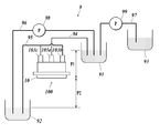
- FIG. 8 is a schematic diagram showing the configuration of the ink circulation mechanism 9.
- the ink circulation mechanism 9 includes a supply subtank 91, a reflux subtank 92, a main tank 93, and the like.
- the supply sub tank 91 stores ink supplied to an ink manifold provided in the inkjet head 100.
- the supply sub-tank 91 is connected to the inlet 103 a by the ink flow path 94.
- the reflux sub-tank 92 is connected to the outlets 103b and 103c by the ink flow path 95, and is discharged from the outlet 103b or the outlet 103c through the ink discharge flow path including the individual discharge flow path 124 and the common discharge flow path 142.
- the ink thus stored is stored.
- the supply subtank 91 and the reflux subtank 92 are connected by an ink flow path 96.
- the ink can be returned from the reflux sub-tank 92 to the supply sub-tank 91 by a pump 98 provided in the ink flow path 96.
- the main tank 93 stores the ink supplied to the supply sub tank 91.
- the main tank 93 is connected to the supply sub tank 91 by the ink flow path 97.
- Ink is supplied from the main tank 93 to the supply sub-tank 91 by the pump 99 provided in the ink flow path 97.
- the supply sub-tank 91 is provided at a position where the liquid level is higher than the ink ejection surface of the head chip 10 (hereinafter also referred to as “position reference surface”). It is provided at a position lower than the position reference plane. Therefore, a pressure P1 due to a water head difference between the position reference surface and the supply sub tank 91 and a pressure P2 due to a water head difference between the position reference surface and the reflux sub tank 92 are generated. As a result, the ink pressure at the inlet 103a is higher than the ink pressure at the outlets 103b and 103c.
- the outlet 103b from the inlet 103a through the ink manifold, the ink supply port 151, the channel 141, the through flow path 121, the individual discharge flow path 124, the common discharge flow path 142, the vertical discharge flow path 133, and the discharge hole 152, An ink flow toward 103c occurs, and ink is supplied to the channel 141 and discharged (refluxed) from the channel 141.
- the pressure P1 and the pressure P2 can be adjusted by changing the amount of ink in each sub tank and the vertical position of each sub tank, thereby adjusting the flow rate of ink.
- FIG. 9 is a diagram showing simulation conditions and results.
- the ink pressure loss in the individual discharge flow path 124 (relative to Comparative Example 1). Ratio) and the size of bubbles and foreign matters that can be discharged.
- 10A, the width and depth of the flow path are 0.05 mm, and the lengths of the first front-stage individual discharge flow path 122a and the second front-stage individual discharge flow path 122b are each 1.5 mm. It was set to 1. 10A, the width and depth of the flow path are 0.06 mm, and the lengths of the first front-stage individual discharge flow path 122a and the second front-stage individual discharge flow path 122b are each 1.5 mm. It was set as Comparative Example 2. 10A, the width and depth of the flow path are 0.06 mm, and the lengths of the first front individual discharge flow path 122a and the second front individual discharge flow path 122b are 1.7 mm, respectively. It was set as Comparative Example 3. The occupied areas of the individual discharge channels 124 in Comparative Examples 1 to 3 are 0.15 mm 2 , 0.18 mm 2 , and 0.20 mm 2 , respectively.
- the length and the cross-sectional shape of the first front-stage individual discharge flow path 122a and the second front-stage individual discharge flow path 122b are equal, and the pressure loss is also equal.
- Example 11 the width and depth of the flow path are 0.07 mm, the lengths of the first front-stage individual discharge flow path 122a and the second front-stage individual discharge flow path 122b are each 0.7 mm, and the rear-stage individual A discharge channel 123 having a length of 1.1 mm was taken as Example 2.
- each flow path in Comparative Examples 1 to 3 Example 1 and Example 2 was in the shape of a square pipe having a square cross section.
- the simulation requires that the area occupied by the individual discharge channel 124 be less than 0.20 mm 2 due to the design of the head chip 10, and the lower limit value of the pressure loss necessary for suppressing the propagation of the pressure wave is a comparative example. It was performed under the assumption that the ratio to 1 was 0.50 or more.
- Example 1 the width and depth of each flow path are increased to 0.06 mm, and the first front-stage individual discharge flow path 122a and the second front-stage individual discharge flow path 122b are shortened to 0.7 mm.
- the latter-stage individual discharge flow path 123 it is possible to increase the bubbles and foreign matters that can be discharged to 0.06 mm while securing the occupied area and pressure loss equivalent to those of Comparative Example 1.
- the width and depth of each flow path are expanded to 0.07 mm as in Example 2, and the bubbles and foreign matters that can be discharged are increased to 0.07 mm, the above-described conditions regarding the occupied area and pressure loss It was confirmed that
- the inkjet head 100 includes the channel 141 serving as an ink storage unit that stores ink, the drive electrode 136 serving as a pressure changing unit that changes the pressure of the ink stored in the channel 141, and the channel. 141, the nozzle 111 that discharges ink in accordance with the fluctuation of the pressure of the ink in the channel 141, and the ink that communicates with the one channel 141 and is discharged from the channel 141 without being supplied to the nozzle 111.
- the first front individual discharge flow path 122a and the second front individual discharge flow path 122b that pass through each, and the rear individual discharge flow path 123 that the first front individual discharge flow path 122a and the second front individual discharge flow path 122b merge.
- the rear individual discharge channel 123 is lengthened. By doing so, it is possible to effectively increase the pressure loss of the ink in the individual discharge channel 124 while suppressing an increase in the area occupied by the individual discharge channel 124.
- the first front-stage individual discharge flow path 122a in the conventional configuration having the individual discharge flow path 124 in which the first front-stage individual discharge flow path 122a and the second front-stage individual discharge flow path 122b are directly connected to the common discharge flow path 142, the first front-stage individual discharge flow path 122a.
- the increase amount of the occupied area of the individual discharge flow path 124 required to increase the pressure loss by a predetermined amount is suppressed. be able to.
- the pressure loss of ink in the individual discharge flow path 124 is effectively increased, and the channel 141 Propagation of pressure waves from the gas to the common discharge channel 142 can be suppressed.
- the pressure waves that have entered the two front-stage individual discharge flow paths from the channel 141 become the rear-stage individual discharge flow path 123.
- the conditions for canceling (weakening) the pressure waves can be easily satisfied. Therefore, propagation of pressure waves from the channel 141 to the common discharge flow path 142 can be more effectively suppressed.
- the pressure loss per unit length in the relatively long first front-stage individual discharge flow path 122b out of the first front-stage individual discharge flow path 122a and the second front-stage individual discharge flow path 122b is expressed as the second front-stage individual discharge flow path.
- the pressure waves that have entered the two front-stage individual discharge flow paths from the channel 141 are also generated.
- downstream individual discharge channel 123 is configured such that the ink pressure loss in the rear individual discharge channel 123 is greater than the ink pressure loss (synthetic pressure loss) in the first front individual discharge channel 122a and the second front individual discharge channel 122b.
- the pressure loss of the ink in the individual discharge flow path 124 can be increased efficiently, that is, in a smaller space.
- the minimum value of the cross-sectional area perpendicular to the ink discharge direction in the rear-stage individual discharge flow path 123 is perpendicular to the ink discharge direction in each of the first front-stage individual discharge flow path 122a and the second front-stage individual discharge flow path 122b. It is more than the minimum value of the cross-sectional area. Thereby, bubbles and foreign substances that can pass through the first front-stage individual discharge flow path 122 a and the second front-stage individual discharge flow path 122 b can be passed through the rear-stage individual discharge flow path 123.
- the length of the rear individual discharge flow path 123 is adjusted to reduce the discharge action of bubbles and foreign substances. Without this, the overall pressure loss of the individual discharge flow path 124 can be increased.
- first front-stage individual discharge flow path 122a and the second front-stage individual discharge flow path 122b are connected to the channel 141 in opposite directions. Thereby, bubbles and foreign matter in the channel 141 can be discharged more effectively.
- the plurality of nozzles 111 included in the plurality of ink ejection units 10 a are arranged along a predetermined direction, and communicate with each nozzle 111 except for the nozzle 111 at one predetermined end of the plurality of nozzles 111.
- the first front-stage individual discharge flow path 122a and the second front-stage individual discharge flow path 122b only the first front-stage individual discharge flow path 122a is adjacent to the nozzle 111 as viewed from the ink ejection direction side. Pass between.
- variety about the nozzle arrangement direction of the separate discharge flow path 124 can be made small. Therefore, even in the inkjet head 100 in which the arrangement density of the nozzles 111 is high, the individual discharge channel 124 having the rear individual discharge channel 123 can be provided.
- the inkjet recording apparatus 1 of the present embodiment includes the inkjet head 100 described above, it is possible to effectively suppress image quality degradation caused by pressure wave propagation and image quality degradation caused by bubbles and foreign matter.
- the present invention is not limited to the above-described embodiments and modifications, and various modifications can be made.
- the individual discharge channel 124 may be provided in the pressure chamber substrate 13 or the nozzle substrate 11.
- the individual discharge channel 124 is not limited to the one formed by providing a groove on the plate surface of the channel spacer substrate 12, and the shape of the nozzle substrate 11 and the channel substrate 12 is formed so as to penetrate the channel spacer substrate 12 in the thickness direction.
- Each flow path may be sealed by bonding the pressure chamber substrate 13.
- the configuration in which the plurality of subsequent individual discharge channels 123 are directly connected to the common discharge channel 142 has been described as an example, but the present invention is not limited thereto. That is, a plurality of subsequent individual discharge channels 123 may communicate with the common discharge channel 142 via another channel, an ink chamber, or the like.
- the common discharge channel 142 has been described as an example including the through channel 121 of the channel spacer substrate 12 and the groove-shaped channel 132 of the pressure chamber substrate 13. Not limited.
- the common discharge channel 142 may be configured by a groove provided on the surface of the channel spacer substrate 12 on the nozzle substrate 11 side.
- the head chip 10 may be constituted by the pressure chamber substrate 13 and the nozzle substrate 11 without providing the flow path spacer substrate 12.
- the individual discharge flow path in this case can be formed by a groove provided on the surface of the pressure chamber substrate 13 on the nozzle substrate 11 side, for example.
- the inkjet head 100 including the shear mode head chip 10 has been described as an example.
- the present invention is not limited to this.
- an ink jet having a vent mode head chip that discharges ink by changing the pressure of ink in the pressure chamber by deforming a piezoelectric element (pressure changing means) fixed to the wall of the pressure chamber as an ink reservoir The present invention may be applied to the head.
- the transport unit 2 is, for example, rotating.
- the recording medium M may be held and conveyed on the outer peripheral surface of the conveying drum.
- the single-pass inkjet recording apparatus 1 has been described as an example.
- the present invention is applied to an inkjet recording apparatus that records an image while scanning the inkjet head 100. May be.
- the present invention can be used for an inkjet head and an inkjet recording apparatus.
Abstract
より効果的に画質低下を抑制することができるインクジェットヘッド及びインクジェット記録装置を提供する。インクジェットヘッド(100)は、インク貯留部(141)と、圧力変動手段(136)と、インク貯留部に連通し、当該インク貯留部内におけるインクの圧力の変動に応じてインクを吐出するノズル(111)と、一のインク貯留部に連通し、当該インク貯留部からノズルに供給されずに排出されるインクがそれぞれ通る複数の前段個別排出流路(122a、122b)と、複数の前段個別排出流路が合流した後段個別排出流路(123)と、を各々有する複数のインク吐出部(10a)と、複数のインク吐出部が有する複数の後段個別排出流路に連通し、当該複数の後段個別排出流路を通ったインクが流入する共通排出流路(142)と、を備える。
Description
本発明は、インクジェットヘッド及びインクジェット記録装置に関する。
従来、インクジェットヘッドに設けられた複数のノズルからインクを吐出させて所望の位置に着弾させることで画像を形成するインクジェット記録装置がある。インクジェット記録装置のインクジェットヘッドは、複数のノズルの各々に対応して、インクを貯留するインク貯留部と、当該インク貯留部内のインクの圧力を変動させる圧力変動手段とが設けられており、インク貯留部内のインクの圧力の変動に応じて、インク貯留部に連通するノズルからインクを吐出させる。
インクジェットヘッドでは、インク貯留部に気泡や異物が混入すると、インクに対して正常に圧力が印加されなくなるため、ノズルからのインクの吐出不良が生じて画質が低下する。このため、従来、複数のノズルに対応する複数のインク貯留部の各々を、個別排出流路を介して共通排出流路に連通させて、各インク貯留部に供給されるインクの一部を気泡や異物とともに個別排出流路及び共通排出流路を介してインクジェットヘッドの外部に排出させる技術がある。この技術では、一のインク貯留部に複数の個別排出流路を連通させることで、気泡や異物をより排出させやすくすることができる(例えば、特許文献1)。
また、このような構成のインクジェットヘッドでは、インク貯留部内のインクの圧力の変動に応じた圧力波が共通排出流路を介して他のいずれかのインク吐出部に伝播すると、当該インク吐出部においてインクに対して所望の圧力を印加することができなくなってインクの吐出特性が変動し、画質の低下に繋がる。このため、個別排出流路に進入した圧力波が共通排出流路に伝播しにくくなるように、個別排出流路を長くしたり、断面積を小さくしたりすることで個別排出流路におけるインクの圧力損失を増大させている。
しかしながら、近年、インクジェットヘッドでは、小型化やノズル配置の高密度化が進んでおり、個別排出流路を配置できる領域には限りがあるため、特に一のインク貯留部に複数の個別排出流路を連通させたインクジェットヘッドでは、個別排出流路を長くできる余地が少ない。このため、個別排出流路を長くする方法では圧力損失を十分に増大させることができず、圧力波の伝播に起因する画質低下を効果的に抑制することが困難である。
一方で、個別排出流路の断面積を小さくすることで圧力損失を増大させると、排出可能な気泡や異物が小さくなるため、インク貯留部内の気泡や異物に起因する画質低下が顕著となってしまう。
このように、一のインク貯留部に複数の個別排出流路を連通させたインクジェットヘッドでは、画質低下を効果的に抑制するのが容易でないという課題がある。
一方で、個別排出流路の断面積を小さくすることで圧力損失を増大させると、排出可能な気泡や異物が小さくなるため、インク貯留部内の気泡や異物に起因する画質低下が顕著となってしまう。
このように、一のインク貯留部に複数の個別排出流路を連通させたインクジェットヘッドでは、画質低下を効果的に抑制するのが容易でないという課題がある。
この発明の目的は、より効果的に画質低下を抑制することができるインクジェットヘッド及びインクジェット記録装置を提供することにある。
上記目的を達成するため、請求項1に記載のインクジェットヘッドの発明は、
インクを貯留するインク貯留部と、
前記インク貯留部に貯留されたインクの圧力を変動させる圧力変動手段と、
前記インク貯留部に連通し、当該インク貯留部内におけるインクの圧力の変動に応じてインクを吐出するノズルと、
一の前記インク貯留部に連通し、当該インク貯留部から前記ノズルに供給されずに排出されるインクがそれぞれ通る複数の前段個別排出流路と、
前記複数の前段個別排出流路が合流した後段個別排出流路と、
を各々有する複数のインク吐出部と、
前記複数のインク吐出部が有する複数の前記後段個別排出流路に連通し、当該複数の後段個別排出流路を通ったインクが流入する共通排出流路と、
を備える。
インクを貯留するインク貯留部と、
前記インク貯留部に貯留されたインクの圧力を変動させる圧力変動手段と、
前記インク貯留部に連通し、当該インク貯留部内におけるインクの圧力の変動に応じてインクを吐出するノズルと、
一の前記インク貯留部に連通し、当該インク貯留部から前記ノズルに供給されずに排出されるインクがそれぞれ通る複数の前段個別排出流路と、
前記複数の前段個別排出流路が合流した後段個別排出流路と、
を各々有する複数のインク吐出部と、
前記複数のインク吐出部が有する複数の前記後段個別排出流路に連通し、当該複数の後段個別排出流路を通ったインクが流入する共通排出流路と、
を備える。
請求項2に記載の発明は、請求項1に記載のインクジェットヘッドにおいて、
前記複数の前段個別排出流路の各々は、当該複数の前段個別排出流路のうち他のいずれかの前段個別排出流路とは長さが異なる。
前記複数の前段個別排出流路の各々は、当該複数の前段個別排出流路のうち他のいずれかの前段個別排出流路とは長さが異なる。
請求項3に記載の発明は、請求項2に記載のインクジェットヘッドにおいて、
前記複数の前段個別排出流路は、長い前段個別排出流路ほど、単位長さ当たりの圧力損失が小さい。
前記複数の前段個別排出流路は、長い前段個別排出流路ほど、単位長さ当たりの圧力損失が小さい。
請求項4に記載の発明は、請求項1から3のいずれか一項に記載のインクジェットヘッドにおいて、
前記複数の前段個別排出流路の各々におけるインクの圧力損失は、当該複数の前段個別排出流路のうち他のいずれかの前段個別排出流路におけるインクの圧力損失と異なる。
前記複数の前段個別排出流路の各々におけるインクの圧力損失は、当該複数の前段個別排出流路のうち他のいずれかの前段個別排出流路におけるインクの圧力損失と異なる。
請求項5に記載の発明は、請求項1から4のいずれか一項に記載のインクジェットヘッドにおいて、
前記後段個別排出流路におけるインクの圧力損失は、前記複数の前段個別排出流路におけるインクの圧力損失より大きい。
前記後段個別排出流路におけるインクの圧力損失は、前記複数の前段個別排出流路におけるインクの圧力損失より大きい。
請求項6に記載の発明は、請求項5に記載のインクジェットヘッドにおいて、
前記後段個別排出流路におけるインクの排出方向に垂直な断面積の最小値は、前記複数の前段個別排出流路の各々におけるインクの排出方向に垂直な断面積の最小値以上である。
前記後段個別排出流路におけるインクの排出方向に垂直な断面積の最小値は、前記複数の前段個別排出流路の各々におけるインクの排出方向に垂直な断面積の最小値以上である。
請求項7に記載の発明は、請求項1から6のいずれか一項に記載のインクジェットヘッドにおいて、
前記複数のインク吐出部の各々は、2つの前記前段個別排出流路を有し、
前記2つの前段個別排出流路は、前記インク貯留部に対して互いに反対向きに接続されている。
前記複数のインク吐出部の各々は、2つの前記前段個別排出流路を有し、
前記2つの前段個別排出流路は、前記インク貯留部に対して互いに反対向きに接続されている。
請求項8に記載の発明は、請求項1から7のいずれか一項に記載のインクジェットヘッドにおいて、
前記複数のインク吐出部の各々は、2つの前記前段個別排出流路を有し、
前記複数のインク吐出部が有する複数の前記ノズルは、所定方向に沿って配列されており、
前記複数のノズルのうち所定の一方の端にあるノズルを除いた各ノズルに連通している前記2つの前段個別排出流路は、一方の前段個別排出流路のみが、前記ノズルからのインクの吐出方向の側から見て、隣り合う前記ノズルの間を通る。
前記複数のインク吐出部の各々は、2つの前記前段個別排出流路を有し、
前記複数のインク吐出部が有する複数の前記ノズルは、所定方向に沿って配列されており、
前記複数のノズルのうち所定の一方の端にあるノズルを除いた各ノズルに連通している前記2つの前段個別排出流路は、一方の前段個別排出流路のみが、前記ノズルからのインクの吐出方向の側から見て、隣り合う前記ノズルの間を通る。
また、上記目的を達成するため、請求項9に記載のインクジェット記録装置の発明は、
請求項1から8のいずれか一項に記載のインクジェットヘッドを備える。
請求項1から8のいずれか一項に記載のインクジェットヘッドを備える。
本発明に従うと、より効果的に画質低下を抑制することができるという効果がある。
以下、本発明のインクジェットヘッド及びインクジェット記録装置に係る実施の形態を図面に基づいて説明する。
図1は、本発明の実施形態であるインクジェット記録装置1の概略構成を示す図である。
インクジェット記録装置1は、搬送部2と、ヘッドユニット3などを備える。
図1は、本発明の実施形態であるインクジェット記録装置1の概略構成を示す図である。
インクジェット記録装置1は、搬送部2と、ヘッドユニット3などを備える。
搬送部2は、図1のX方向に延びる回転軸を中心に回転する2本の搬送ローラー2a、2bにより内側が支持された輪状の搬送ベルト2cを備える。搬送部2は、搬送ベルト2cの搬送面上に記録媒体Mが載置された状態で搬送ローラー2aが図示略の搬送モーターの動作に応じて回転して搬送ベルト2cが周回移動することで記録媒体Mを搬送ベルト2cの移動方向(搬送方向;図1のY方向)に搬送する。
記録媒体Mは、一定の寸法に裁断された枚葉紙とすることができる。記録媒体Mは、図示略の給紙装置により搬送ベルト2c上に供給され、ヘッドユニット3からインクが吐出されて画像が記録された後に搬送ベルト2cから所定の排紙部に排出される。なお、記録媒体Mとしては、ロール紙が用いられてもよい。また、記録媒体Mとしては、普通紙や塗工紙といった紙のほか、布帛又はシート状の樹脂等、表面に着弾したインクを定着させることが可能な種々の媒体を用いることができる。
ヘッドユニット3は、搬送部2により搬送される記録媒体Mに対して画像データに基づいて適切なタイミングでインクを吐出して画像を記録する。本実施形態のインクジェット記録装置1では、イエロー(Y)、マゼンタ(M)、シアン(C)、ブラック(K)の4色のインクにそれぞれ対応する4つのヘッドユニット3が記録媒体Mの搬送方向上流側からY、M、C、Kの色の順に所定の間隔で並ぶように配列されている。なお、ヘッドユニット3の数は3つ以下又は5つ以上であってもよい。
図2は、ヘッドユニット3の構成を示す模式図であり、ヘッドユニット3を搬送ベルト2cの搬送面に相対する側から見た平面図である。ヘッドユニット3は、板状の基部3aと、基部3aに設けられた貫通孔に篏合した状態で基部3aに固定された複数の(ここでは8つの)インクジェットヘッド100とを有する。インクジェットヘッド100は、ノズル111の開口部が設けられたノズル開口面11aが基部3aの貫通孔から-Z方向に向けて露出した状態で基部3aに固定されている。
インクジェットヘッド100では、複数のノズル111が記録媒体Mの搬送方向と交差する方向(本実施形態では搬送方向と直交する幅方向、すなわちX方向)に等間隔にそれぞれ配列されている。すなわち、各インクジェットヘッド100は、X方向に等間隔に一次元配列されたノズル111の列(ノズル列)を有している。
なお、インクジェットヘッド100は、ノズル列を複数有していても良い。この場合には、複数のノズル列は、ノズル111のX方向についての位置が重ならないようにX方向の位置が互いにずらされて配置される。
なお、インクジェットヘッド100は、ノズル列を複数有していても良い。この場合には、複数のノズル列は、ノズル111のX方向についての位置が重ならないようにX方向の位置が互いにずらされて配置される。
ヘッドユニット3における8つのインクジェットヘッド100は、ノズル111のX方向についての配置範囲が連続するように千鳥格子状に配置されている。ヘッドユニット3に含まれるノズル111のX方向についての配置範囲は、搬送ベルト2cにより搬送される記録媒体Mのうち画像が記録可能な領域のX方向の幅をカバーしている。ヘッドユニット3は、画像の記録時には位置が固定されて用いられ、記録媒体Mの搬送に応じて搬送方向についての所定間隔(搬送方向間隔)の各位置に対してノズル111からインクを吐出することで、シングルパス方式で画像を記録する。
図3は、インクジェットヘッド100の斜視図である。
インクジェットヘッド100は、筐体101と、筐体101の下端で筐体101と篏合する外装部材102とを備え、筐体101及び外装部材102の内部に主要な構成要素が収容されている。このうち外装部材102には、外部からインクが供給されるインレット103a、及びインクが外部に排出されるアウトレット103b、103cが設けられている。また、外装部材102には、インクジェットヘッド100をヘッドユニット3の基部3aに取り付けるための複数の取付穴104が設けられている。
インクジェットヘッド100は、筐体101と、筐体101の下端で筐体101と篏合する外装部材102とを備え、筐体101及び外装部材102の内部に主要な構成要素が収容されている。このうち外装部材102には、外部からインクが供給されるインレット103a、及びインクが外部に排出されるアウトレット103b、103cが設けられている。また、外装部材102には、インクジェットヘッド100をヘッドユニット3の基部3aに取り付けるための複数の取付穴104が設けられている。
図4は、インクジェットヘッド100の主要部の分解斜視図である。
図4では、インクジェットヘッド100の構成部材のうち、外装部材102の内部に収容されている主要な構成部材が示されている。具体的には、図4では、ノズル基板11、流路スペーサー基板12及び圧力室基板13を有するヘッドチップ10と、ヘッドチップ10に固着された配線基板15と、配線基板15に電気的に接続されたFPC20(Flexible Printed Circuit)とが示されている。
図4では、インクジェットヘッド100のノズル開口面11aが上方となるように、すなわち図3とは上下が反転されるように各部材が描かれている。以下では、各基板の-Z方向側の面を上面、+Z方向側の面を下面とも記す。
図4では、インクジェットヘッド100の構成部材のうち、外装部材102の内部に収容されている主要な構成部材が示されている。具体的には、図4では、ノズル基板11、流路スペーサー基板12及び圧力室基板13を有するヘッドチップ10と、ヘッドチップ10に固着された配線基板15と、配線基板15に電気的に接続されたFPC20(Flexible Printed Circuit)とが示されている。
図4では、インクジェットヘッド100のノズル開口面11aが上方となるように、すなわち図3とは上下が反転されるように各部材が描かれている。以下では、各基板の-Z方向側の面を上面、+Z方向側の面を下面とも記す。
ヘッドチップ10は、ノズル111が設けられたノズル基板11と、ノズル111に連通する貫通流路121等が設けられた流路スペーサー基板12と、貫通流路121を介してノズル111に連通する圧力室131(インク貯留部)等が設けられた圧力室基板13と、が積層された構造を有している。以下では、このうち流路スペーサー基板12及び圧力室基板13からなる基板を流路基板14と記す。
ノズル基板11、流路スペーサー基板12及び圧力室基板13と、配線基板15とは、いずれもX方向に長尺な略四角柱状の板状部材である。
ノズル基板11、流路スペーサー基板12及び圧力室基板13と、配線基板15とは、いずれもX方向に長尺な略四角柱状の板状部材である。
ノズル基板11は、厚さ方向(Z方向)に貫通する孔であるノズル111がX方向に沿って列をなすように設けられているポリイミドの基板である。ノズル基板11の上面は、インクジェットヘッド100のノズル開口面11aをなす。ノズル基板11の厚さ(したがって、ノズル111のインク吐出方向の長さ)は、例えば数十μmから数百μm程度である。
なお、ノズル111の内壁面は、Z方向に垂直な断面積が、インク吐出側の開口部に近いほど小さくなるようなテーパー形状を有していても良い。また、ノズル基板11としては、ポリイミド以外の各種樹脂の基板や、シリコン基板、SUSなどの金属基板などを用いても良い。
なお、ノズル111の内壁面は、Z方向に垂直な断面積が、インク吐出側の開口部に近いほど小さくなるようなテーパー形状を有していても良い。また、ノズル基板11としては、ポリイミド以外の各種樹脂の基板や、シリコン基板、SUSなどの金属基板などを用いても良い。
また、ノズル基板11のノズル開口面11aには、フッ素樹脂粒子等の撥液性物質を含む撥水膜が設けられている。撥水膜を設けることで、ノズル開口面11aに対するインクや異物の付着を抑えることができ、当該インクや異物等の付着に起因するインク吐出不良の発生を抑制することができる。
流路スペーサー基板12には、ノズル111に連通する貫通流路121と、貫通流路121から分岐する第1前段個別排出流路122a及び第2前段個別排出流路122bと、第1前段個別排出流路122a及び第2前段個別排出流路122bが合流した後段個別排出流路123と、後段個別排出流路123に連通する帯状貫通流路125と、が設けられている。このうち貫通流路121、第1前段個別排出流路122a、第2前段個別排出流路122b及び後段個別排出流路123は、複数のノズル111の各々に対応して設けられている。
また、圧力室基板には、貫通流路121に連通する圧力室131と、帯状貫通流路125に連通する溝状流路132と、溝状流路132から分岐する垂直排出流路133と、が設けられている。このうち圧力室131は、複数のノズル111の各々に対応して設けられている。
また、圧力室基板には、貫通流路121に連通する圧力室131と、帯状貫通流路125に連通する溝状流路132と、溝状流路132から分岐する垂直排出流路133と、が設けられている。このうち圧力室131は、複数のノズル111の各々に対応して設けられている。
流路スペーサー基板12及び圧力室基板13は、Z方向から見た形状がノズル基板11とほぼ同一である直方体形状の板状部材である。
本実施形態の流路スペーサー基板12は、シリコン基板からなる。流路スペーサー基板12の厚さは、特には限られないが、数百μm程度とされる。流路スペーサー基板12の上面にはノズル基板11が、また下面には圧力室基板13が、それぞれ接着剤を介して接着(固着)されている。
圧力室基板13の材質は、セラミックスの圧電体(電圧の印加に応じて変形する部材)である。このような圧電体の例としては、PZT(チタン酸ジルコン酸鉛)、ニオブ酸リチウム、チタン酸バリウム、チタン酸鉛、メタニオブ酸鉛などが挙げられる。本実施形態の圧力室基板13では、PZTが用いられている。
本実施形態の流路スペーサー基板12は、シリコン基板からなる。流路スペーサー基板12の厚さは、特には限られないが、数百μm程度とされる。流路スペーサー基板12の上面にはノズル基板11が、また下面には圧力室基板13が、それぞれ接着剤を介して接着(固着)されている。
圧力室基板13の材質は、セラミックスの圧電体(電圧の印加に応じて変形する部材)である。このような圧電体の例としては、PZT(チタン酸ジルコン酸鉛)、ニオブ酸リチウム、チタン酸バリウム、チタン酸鉛、メタニオブ酸鉛などが挙げられる。本実施形態の圧力室基板13では、PZTが用いられている。
流路スペーサー基板12の貫通流路121は、流路スペーサー基板12をZ方向に貫通する貫通孔であり、Z方向に垂直な断面がY方向に長い矩形をなしている。また、圧力室基板13の圧力室131は、圧力室基板13をZ方向に貫通する貫通孔であり、Z方向に垂直な断面の形状は、貫通流路121と同一である。流路スペーサー基板12と圧力室基板13とが接合された状態では、貫通流路121及び圧力室131が一繋がりとなって、チャネル141(インク貯留部)を構成する。チャネル141は、Z方向から見てノズル111と重なる位置に設けられており、ノズル111に連通している。また、各チャネル141には、配線基板15に設けられたインク供給口151を介してインクが供給されて貯留される。
図5は、圧力室基板13の下面の拡大平面図である。
図5に示されるように、各圧力室131は、X方向に隣り合う圧力室131との間が圧電体の隔壁134により仕切られている。各圧力室131の隔壁134の内壁面には、金属の駆動電極136(圧力変動手段)が設けられている。また、圧力室基板13の表面のうち圧力室131の開口部の+Y方向側の近傍領域には、駆動電極136に電気的に接続された金属の接続電極135が設けられている。接続電極135は、図4に示される配線基板15の配線153、及びFPC20の配線21を介して外部の駆動回路に電気的に接続される。
図5に示されるように、各圧力室131は、X方向に隣り合う圧力室131との間が圧電体の隔壁134により仕切られている。各圧力室131の隔壁134の内壁面には、金属の駆動電極136(圧力変動手段)が設けられている。また、圧力室基板13の表面のうち圧力室131の開口部の+Y方向側の近傍領域には、駆動電極136に電気的に接続された金属の接続電極135が設けられている。接続電極135は、図4に示される配線基板15の配線153、及びFPC20の配線21を介して外部の駆動回路に電気的に接続される。
圧力室基板13では、接続電極135を介して駆動電極136に印加された駆動信号に応じて隔壁134がシアモード型の変位を繰り返すことで、圧力室131内(したがって、チャネル141内の)のインクの圧力が変動する。この圧力の変動に応じて、チャネル141内のインクがノズル111から吐出される。すなわち、本実施形態のヘッドチップ10は、シアモード型のインク吐出を行うヘッドチップである。
なお、図4及び図5におけるX方向について一つ置きのチャネル141の形成位置に、チャネル141に代えて、インクの流入経路を有しない空気室を設けても良い。このような構成とすることで、チャネル141に隣接する隔壁134が変形した際に、他のチャネル141に当該変形の影響が及ばないようにすることができる。
なお、図4及び図5におけるX方向について一つ置きのチャネル141の形成位置に、チャネル141に代えて、インクの流入経路を有しない空気室を設けても良い。このような構成とすることで、チャネル141に隣接する隔壁134が変形した際に、他のチャネル141に当該変形の影響が及ばないようにすることができる。
図4に示されるように、流路スペーサー基板12には、チャネル141の配列方向(X方向)に沿って延び、流路スペーサー基板12をZ方向に貫通する帯状貫通流路125が設けられている。また、圧力室基板13の流路スペーサー基板12との接合面には、Z方向から見て帯状貫通流路125と重なる位置に溝状流路132が設けられている。帯状貫通流路125及び溝状流路132は、流路スペーサー基板12と圧力室基板13とが接合された状態において、X方向に延びる共通排出流路142を構成する。このような構成の共通排出流路142は、流路スペーサー基板12とノズル基板11との接合面(したがって、流路基板14とノズル基板11との接合面)に沿って延び、側壁の一部がノズル基板11によって構成されている。
また、共通排出流路142の+X方向側の端部には、圧力室基板13をZ方向に貫通する垂直排出流路133が接続されている。
また、共通排出流路142の+X方向側の端部には、圧力室基板13をZ方向に貫通する垂直排出流路133が接続されている。
また、上述のとおり、流路スペーサー基板12には、複数の貫通流路121(チャネル141)の各々から分岐する第1前段個別排出流路122a及び第2前段個別排出流路122bと、第1前段個別排出流路122a及び第2前段個別排出流路122bが合流した後段個別排出流路123とが設けられており、後段個別排出流路123が帯状貫通流路125に接続されている。第1前段個別排出流路122a、第2前段個別排出流路122b及び後段個別排出流路123は、流路スペーサー基板12の上面側の表面に沿って設けられた溝状の流路であり、側壁の一部がノズル基板11によって構成されている。以下では、第1前段個別排出流路122a、第2前段個別排出流路122b及び後段個別排出流路123を合わせて個別排出流路124とも記す。個別排出流路124の詳細な構成については後述する。
このような構成の流路スペーサー基板12及び圧力室基板13からなる流路基板14では、チャネル141に供給されたインクのうちノズル111から吐出されなかったインクの一部が、個別排出流路124及び共通排出流路142を介して外部に排出される。すなわち、個別排出流路124及び共通排出流路142を通ったインクは、垂直排出流路133、及び配線基板15に設けられた排出孔152を通ってアウトレット103b(又はアウトレット103c)からインクジェットヘッド100の外部に排出される。
インク供給口151からチャネル141に供給されるインクの流れや、チャネル141から個別排出流路124及び共通排出流路142を通って排出されるインクの流れは、インクジェット記録装置1が有するインク循環機構9(図8)により発生させることができる。インク循環機構9の構成については、後述する。
配線基板15は、圧力室基板13との接合領域を確保する観点から圧力室基板13の面積よりも大きな面積を有する平板状の基板であることが好ましく、接着剤を介して圧力室基板13の下面に接着されている。配線基板15としては、例えばガラス、セラミックス、シリコン、プラスチックなどの基板を用いることができる。
配線基板15には、Z方向から見てチャネル141と重なる位置に複数のインク供給口151が設けられており、また、垂直排出流路133と重なる位置に排出孔152が設けられている。また、配線基板15の圧力室基板13との接着面には、複数のインク供給口151の各々の端部から配線基板15の端部に向かって延びる複数の配線153が設けられている。
配線基板15の下面には、図示しないインクマニホールド(共通インク室)が接続されており、当該インクマニホールドからインク供給口151にインクが供給される。
配線基板15の下面には、図示しないインクマニホールド(共通インク室)が接続されており、当該インクマニホールドからインク供給口151にインクが供給される。
圧力室基板13と配線基板15とは、導電性粒子を含有させた導電性接着剤を介して接着される。これにより、圧力室基板13の表面の接続電極135と、配線基板15上の配線153とが、導電性粒子を介して電気的に接続される。
また、配線基板15のうち配線153が設けられている端部には、FPC20が、例えばACF(異方性導電フィルム)を介して接続される。この接続により、配線基板15の複数の配線153と、FPC20上の複数の配線21とが、一対一で対応するようにそれぞれ電気的に接続される。
次に、個別排出流路124の詳細な構成について説明する。
図6は、個別排出流路124の構成を示す平面図である。図6は、流路スペーサー基板12の上面のうち個別排出流路124の形成領域を拡大して示した図である。この個別排出流路124と、ノズル111と、チャネル141と、上述の駆動電極136と、により、ノズル111からインクを吐出させるための機構であるインク吐出部10aが構成される。したがって、ヘッドチップ10には、ノズル111の数と同一の数のインク吐出部10aが設けられている。
図6は、個別排出流路124の構成を示す平面図である。図6は、流路スペーサー基板12の上面のうち個別排出流路124の形成領域を拡大して示した図である。この個別排出流路124と、ノズル111と、チャネル141と、上述の駆動電極136と、により、ノズル111からインクを吐出させるための機構であるインク吐出部10aが構成される。したがって、ヘッドチップ10には、ノズル111の数と同一の数のインク吐出部10aが設けられている。
図6に示されるように、複数のチャネル141の各々からは、-Y方向側に第1前段個別排出流路122aが分岐し、+Y方向側に第2前段個別排出流路122bが分岐している。すなわち、第1前段個別排出流路122a及び第2前段個別排出流路122bは、チャネル141に対して互いに反対向きに接続されている。より詳しくは、第1前段個別排出流路122a及び第2前段個別排出流路122bは、平面視でチャネル141がなす長矩形において対向する両端(一対の短辺)からそれぞれ分岐している。ここで、チャネル141に対して反対向きに接続されている、とは、各流路におけるインクの排出方向が反対向きであることをいう。よって、2つの前段個別排出流路が一直線上にある構成に限られず、互いに異なる直線上にある構成であっても良い。
また、第1前段個別排出流路122a及び第2前段個別排出流路122bは、+Y方向に延びる一つの後段個別排出流路123に合流している。第2前段個別排出流路122bと、後段個別排出流路123とは、一直線状に繋がっており、第1前段個別排出流路122aは、貫通流路121の側方(-X方向側)を回り込んだ後に後段個別排出流路123に対して垂直な方向から合流する。具体的には、第1前段個別排出流路122aは、貫通流路121から-Y方向側に分岐した後に-X方向、+Y方向に順に折れて貫通流路121の側方を通り、その後、+X方向に折れて後段個別排出流路123に接続される。よって、-X方向側の端にあるノズル111を除いた各ノズル111に連通している第1前段個別排出流路122a及び第2前段個別排出流路122bのうち、第1前段個別排出流路122aのみが、Z方向(ノズル111からのインクの吐出方向の側)から見て、隣り合うノズル111の間を通るようになっている。
このような構成により、チャネル141に供給されたインクのうちノズル111から吐出されないインクの一部が、第1前段個別排出流路122a又は第2前段個別排出流路122b、及び後段個別排出流路123を介して共通排出流路142に排出される。これにより、チャネル141に混入した気泡や異物が、インクとともに共通排出流路142に排出されるようになっている。
図7は、個別排出流路124の流路抵抗を説明する図である。
図7では、第1前段個別排出流路122aの流路抵抗Ra、第2前段個別排出流路122bの流路抵抗Rb、及び後段個別排出流路123の流路抵抗Rcを用いて個別排出流路124の等価回路が示されている。流路抵抗Ra及び流路抵抗Rbは、チャネルに対して並列に接続されており、この並列接続された流路抵抗Ra及び流路抵抗Rbの下流側に、流路抵抗Rcが直列に接続されて共通排出流路142に繋がっている。
このような構成の個別排出流路124における全体の合成流路抵抗Rは、以下の式(1)により表される。
R=Ra・Rb/(Ra+Rb)+Rc …(1)
図7では、第1前段個別排出流路122aの流路抵抗Ra、第2前段個別排出流路122bの流路抵抗Rb、及び後段個別排出流路123の流路抵抗Rcを用いて個別排出流路124の等価回路が示されている。流路抵抗Ra及び流路抵抗Rbは、チャネルに対して並列に接続されており、この並列接続された流路抵抗Ra及び流路抵抗Rbの下流側に、流路抵抗Rcが直列に接続されて共通排出流路142に繋がっている。
このような構成の個別排出流路124における全体の合成流路抵抗Rは、以下の式(1)により表される。
R=Ra・Rb/(Ra+Rb)+Rc …(1)
ここで、流路抵抗は、インクの流体が流路を流れるときに、壁面との摩擦や、乱流の発生などによって失われるエネルギーの大きさを表している。このエネルギー損失は、流路においてインクの圧力損失として現れる。よって、流路抵抗(合成流路抵抗)は、流路におけるインクの圧力損失(合成圧力損失)の大きさを表す。
チャネル141内のインクの圧力の変動に応じた圧力波が個別排出流路124及び共通排出流路142を通っていずれかのインク吐出部10aのチャネル141に伝播(反射)すると、当該チャネル141においてインクに対して所望の圧力を印加することができなくなり、インクの吐出特性の変動(クロストーク)が生じて画質の低下に繋がる。このため、圧力波が個別排出流路124を通って共通排出流路142に伝播しにくくなるように、個別排出流路124におけるインクの圧力損失(流路抵抗)は、必要なインクの排出量を確保できる範囲で大きいことが望ましい。
ただし、個別排出流路124を通過できる気泡や異物をできるだけ大きくする観点から、個別排出流路124の各位置での断面積(インクの排出方向に垂直な断面の面積をいう。以下同じ)を確保した上で、流路を長くすることで圧力損失を増大させることが望ましい。しかしながら、近年、インクジェットヘッドでは、小型化やノズル配置の高密度化が進んでおり、第1前段個別排出流路122a及び第2前段個別排出流路122bを配置できる領域には限りがあるため、第1前段個別排出流路122a及び第2前段個別排出流路122bを長くして直接共通排出流路142に接続させる方法では流路を十分に長くできず(すなわち、圧力損失を十分に増大させることができず)、圧力波の伝播に起因する画質低下を十分に抑制することが困難である。
ただし、個別排出流路124を通過できる気泡や異物をできるだけ大きくする観点から、個別排出流路124の各位置での断面積(インクの排出方向に垂直な断面の面積をいう。以下同じ)を確保した上で、流路を長くすることで圧力損失を増大させることが望ましい。しかしながら、近年、インクジェットヘッドでは、小型化やノズル配置の高密度化が進んでおり、第1前段個別排出流路122a及び第2前段個別排出流路122bを配置できる領域には限りがあるため、第1前段個別排出流路122a及び第2前段個別排出流路122bを長くして直接共通排出流路142に接続させる方法では流路を十分に長くできず(すなわち、圧力損失を十分に増大させることができず)、圧力波の伝播に起因する画質低下を十分に抑制することが困難である。
そこで、本実施形態のインクジェットヘッド100では、第1前段個別排出流路122a及び第2前段個別排出流路122bの必要な断面積を確保しつつ、第1前段個別排出流路122a及び第2前段個別排出流路122bを後段個別排出流路123に合流させた上で後段個別排出流路123を長くすることで、個別排出流路124の全体の形成領域を小さく抑えながら、圧力損失を十分に増大させることができるようになっている。図6では、後段個別排出流路123が一直線状となっているが、使用できる領域の大きさや、必要な圧力損失の大きさによっては、蛇行させても良い。
このような構成により、後段個別排出流路123におけるインクの圧力損失は、第1前段個別排出流路122a及び第2前段個別排出流路122bにおけるインクの圧力損失(合成圧力損失)より大きくなっている。
また、後段個別排出流路123における断面積の最小値は、第1前段個別排出流路122a及び第2前段個別排出流路122bの各々における断面積の最小値以上とされている。これにより、第1前段個別排出流路122a及び第2前段個別排出流路122bを通過可能な気泡や異物を、後段個別排出流路123においても通過させることができるようになっている。換言すれば、後段個別排出流路123において気泡や異物の排出に必要な断面積を確保した上で、後段個別排出流路123の長さを調整することで、個別排出流路124の全体の圧力損失を増大させている。
また、後段個別排出流路123における断面積の最小値は、第1前段個別排出流路122a及び第2前段個別排出流路122bの各々における断面積の最小値以上とされている。これにより、第1前段個別排出流路122a及び第2前段個別排出流路122bを通過可能な気泡や異物を、後段個別排出流路123においても通過させることができるようになっている。換言すれば、後段個別排出流路123において気泡や異物の排出に必要な断面積を確保した上で、後段個別排出流路123の長さを調整することで、個別排出流路124の全体の圧力損失を増大させている。
また、第1前段個別排出流路122a及び第2前段個別排出流路122bのうち第1前段個別排出流路122aのみがチャネル141の側方を回り込む構成のため、第1前段個別排出流路122aの長さと、第2前段個別排出流路122bの長さとが異なっている。この結果、第1前段個別排出流路122aにおけるインクの圧力損失と、第2前段個別排出流路122bにおけるインクの圧力損失とが異なっている。このように2つの前段個別排出流路の長さや圧力損失を異ならせることで、チャネル141から2つの前段個別排出流路に入った圧力波が後段個別排出流路123で合流したときに、圧力波同士が打ち消し合う(弱め合う)ための条件を満たしやすくなっている。
ただし、第1前段個別排出流路122a及び第2前段個別排出流路122bでインクの圧力損失の差が大きすぎると、チャネル141から第1前段個別排出流路122aに流入するインク量と第2前段個別排出流路122bに流入するインク量との差が大きくなってしまい、一方の前段個別排出流路を介した気泡や異物の排出効果が得られにくくなってしまう。このため、第1前段個別排出流路122a及び第2前段個別排出流路122bのうち相対的に長い第1前段個別排出流路122aにおける単位長さ当たりの圧力損失(流路全体における圧力損失を長さで除した値)を、第2前段個別排出流路122bにおける単位長さ当たりの圧力損失より小さくして、圧力損失の差を縮小することが望ましい。例えば、各前段個別排出流路における断面積が均一である場合には、相対的に長い第1前段個別排出流路122aの断面積を、第2前段個別排出流路122bの断面積より大きくすることで、第1前段個別排出流路122aにおける単位長さ当たりの圧力損失を相対的に小さくして、2つの前段個別排出流路における圧力損失の差を縮小することができる。
ただし、第1前段個別排出流路122a及び第2前段個別排出流路122bでインクの圧力損失の差が大きすぎると、チャネル141から第1前段個別排出流路122aに流入するインク量と第2前段個別排出流路122bに流入するインク量との差が大きくなってしまい、一方の前段個別排出流路を介した気泡や異物の排出効果が得られにくくなってしまう。このため、第1前段個別排出流路122a及び第2前段個別排出流路122bのうち相対的に長い第1前段個別排出流路122aにおける単位長さ当たりの圧力損失(流路全体における圧力損失を長さで除した値)を、第2前段個別排出流路122bにおける単位長さ当たりの圧力損失より小さくして、圧力損失の差を縮小することが望ましい。例えば、各前段個別排出流路における断面積が均一である場合には、相対的に長い第1前段個別排出流路122aの断面積を、第2前段個別排出流路122bの断面積より大きくすることで、第1前段個別排出流路122aにおける単位長さ当たりの圧力損失を相対的に小さくして、2つの前段個別排出流路における圧力損失の差を縮小することができる。
なお、1つのチャネル141から3つ以上の前段個別排出流路を分岐させ、これらの前段個別排出流路を後段個別排出流路123に合流させる構成としても良い。この場合も、複数の前段個別排出流路の各々の長さが、他のいずれかの前段個別排出流路の長さと異なるようにすることが望ましい。その上で、複数の前段個別排出流路のうち長い前段個別排出流路ほど単位長さ当たりの圧力損失が小さくなるようにすれば良い。また、複数の前段個別排出流路の各々におけるインクの圧力損失が、他のいずれかの前段個別排出流路におけるインクの圧力損失と異なるようにすることが好ましい。
次に、インクジェットヘッド100内においてインクを還流させて排出させるためのインク循環機構9の構成について説明する。
図8は、インク循環機構9の構成を示す模式図である。
インク循環機構9は、供給用サブタンク91、還流用サブタンク92及びメインタンク93などを備える。
供給用サブタンク91は、インクジェットヘッド100に設けられたインクマニホールドに供給されるインクを貯留する。供給用サブタンク91は、インク流路94によってインレット103aに接続されている。
還流用サブタンク92は、インク流路95によってアウトレット103b、103cに接続されており、個別排出流路124及び共通排出流路142を含む上述のインク排出流路を通ってアウトレット103b又はアウトレット103cから排出されたインクを貯留する。
供給用サブタンク91及び還流用サブタンク92は、インク流路96で接続されている。そして、インク流路96に設けられたポンプ98により、還流用サブタンク92から供給用サブタンク91にインクを戻すことができるようになっている。
メインタンク93は、供給用サブタンク91に供給されるインクを貯留する。メインタンク93は、インク流路97によって供給用サブタンク91に接続されている。また、インク流路97に設けられたポンプ99により、メインタンク93から供給用サブタンク91にインクが供給される。
供給用サブタンク91は、その液面が、ヘッドチップ10のインク吐出面(以下、「位置基準面」とも記す)より高くなる位置に設けられ、還流用サブタンク92の液面は、その液面が位置基準面より低くなる位置に設けられている。よって、位置基準面と供給用サブタンク91との水頭差による圧力P1と、位置基準面と還流用サブタンク92との水頭差による圧力P2が生じている。この結果、インレット103aにおけるインクの圧力がアウトレット103b、103cにおけるインクの圧力よりも高くなっている。この圧力差により、インレット103aからインクマニホールド、インク供給口151、チャネル141、貫通流路121、個別排出流路124、共通排出流路142、垂直排出流路133、排出孔152を経てアウトレット103b、103cに向かうインクの流れが生じ、チャネル141へのインク供給、及びチャネル141からのインクの排出(還流)がなされるようになっている。また、各サブタンク内のインク量や、各サブタンクの鉛直方向の位置を変更することで、圧力P1及び圧力P2を調整することができ、これによりインクの流速を調整することができる。
次に、本発明の実施形態の効果を確認するために行ったシミュレーションについて説明する。
図9は、シミュレーションの条件及び結果を示す図である。
このシミュレーションでは、従来の構成の比較例1~比較例3、及び本発明の実施形態である実施例1、実施例2の各々について、個別排出流路124におけるインクの圧力損失(比較例1に対する比率)と、排出可能な気泡や異物の大きさとを評価した。
図9は、シミュレーションの条件及び結果を示す図である。
このシミュレーションでは、従来の構成の比較例1~比較例3、及び本発明の実施形態である実施例1、実施例2の各々について、個別排出流路124におけるインクの圧力損失(比較例1に対する比率)と、排出可能な気泡や異物の大きさとを評価した。
比較例1~比較例3は、図10Aに示されるように、チャネル141から分岐した第1前段個別排出流路122a及び第2前段個別排出流路122bをそのまま共通排出流路142に接続させた構成であり、その等価回路は、図10Bに示されているとおりである。比較例1~比較例3における個別排出流路124(第1前段個別排出流路122a及び第2前段個別排出流路122b)の全体の流路抵抗Rは、以下の式(2)を満たす。
R=Ra・Rb/(Ra+Rb) …(2)
R=Ra・Rb/(Ra+Rb) …(2)
図10Aの構成において、流路の幅及び深さを0.05mmとし、第1前段個別排出流路122a及び第2前段個別排出流路122bの長さをそれぞれ1.5mmとしたものを比較例1とした。
また、図10Aの構成において、流路の幅及び深さを0.06mmとし、第1前段個別排出流路122a及び第2前段個別排出流路122bの長さをそれぞれ1.5mmとしたものを比較例2とした。
また、図10Aの構成において、流路の幅及び深さを0.06mmとし、第1前段個別排出流路122a及び第2前段個別排出流路122bの長さをそれぞれ1.7mmとしたものを比較例3とした。
比較例1~比較例3の個別排出流路124の占有面積は、それぞれ0.15mm2、0.18mm2、0.20mm2である。
また、図10Aの構成において、流路の幅及び深さを0.06mmとし、第1前段個別排出流路122a及び第2前段個別排出流路122bの長さをそれぞれ1.5mmとしたものを比較例2とした。
また、図10Aの構成において、流路の幅及び深さを0.06mmとし、第1前段個別排出流路122a及び第2前段個別排出流路122bの長さをそれぞれ1.7mmとしたものを比較例3とした。
比較例1~比較例3の個別排出流路124の占有面積は、それぞれ0.15mm2、0.18mm2、0.20mm2である。
実施例1及び実施例2は、簡便のため、図11に示されるように第1前段個別排出流路122a及び第2前段個別排出流路122bの長さ及び断面形状が等しく、圧力損失も等しい構成とした。
図11の構成において、流路の幅及び深さを0.06mmとし、第1前段個別排出流路122a及び第2前段個別排出流路122bの長さをそれぞれ0.7mmとし、後段個別排出流路123の長さを1.1mmとしたものを実施例1とした。
また、図11の構成において、流路の幅及び深さを0.07mmとし、第1前段個別排出流路122a及び第2前段個別排出流路122bの長さをそれぞれ0.7mmとし、後段個別排出流路123の長さを1.1mmとしたものを実施例2とした。
実施例1及び実施例2の個別排出流路124の占有面積は、それぞれ0.15mm2、0.18mm2である。
なお、比較例1~3、実施例1及び実施例2における各流路は、断面が正方形の角パイプ状のものとした。
シミュレーションは、ヘッドチップ10の設計上、個別排出流路124の占有面積を0.20mm2未満に抑える必要があり、圧力波の伝播の抑制のために必要な圧力損失の下限値が、比較例1に対する比率で0.50以上である、との想定の下で行った。
シミュレーションの結果、比較例1の構成に対して、比較例2のように各流路の幅及び深さを0.06mmに大きくすると、排出可能な気泡や異物が0.05mmから0.06mmに大きくなる一方で、圧力損失が低下して比較例1に対する比率で0.48となり、上述の下限値を下回ってしまうことが確認された。
また比較例2の構成に対して、比較例3のように、第1前段個別排出流路122a及び第2前段個別排出流路122bを1.7mmに長くすると、圧力損失の比率が0.55に改善して下限値を上回るものの、占有面積が0.20mm2に拡大して占有面積の条件を満たさなくなることが確認された。
また比較例2の構成に対して、比較例3のように、第1前段個別排出流路122a及び第2前段個別排出流路122bを1.7mmに長くすると、圧力損失の比率が0.55に改善して下限値を上回るものの、占有面積が0.20mm2に拡大して占有面積の条件を満たさなくなることが確認された。
これに対し、実施例1のように、各流路の幅及び深さを0.06mmに拡大し、第1前段個別排出流路122a及び第2前段個別排出流路122bを0.7mmに短くした上で後段個別排出流路123を設けることで、比較例1と同等の占有面積及び圧力損失を確保した上で、排出可能な気泡や異物を0.06mmに大きくできることが確認された。
また、実施例2のように、各流路の幅及び深さを0.07mmに拡大し、排出可能な気泡や異物を0.07mmまで大きくしても、占有面積及び圧力損失に関する上記の条件を満たすことが確認された。
また、実施例2のように、各流路の幅及び深さを0.07mmに拡大し、排出可能な気泡や異物を0.07mmまで大きくしても、占有面積及び圧力損失に関する上記の条件を満たすことが確認された。
このように、後段個別排出流路123を設けた本発明の実施例によれば、限られた個別排出流路124の配置スペースで、圧力波の伝播を抑制できる十分な圧力損失を確保した上で、より大きな気泡や異物を排出できることが確認された。また、図9には記載していないが、個別排出流路124の配置スペースや流路の断面積(排出可能な異物の大きさ)を比較例1の値に維持し、後段個別排出流路123を長くした本発明の実施例によれば、個別排出流路124の圧力損失を増大させることも可能である。
以上のように、本実施形態のインクジェットヘッド100は、インクを貯留するインク貯留部としてのチャネル141と、チャネル141に貯留されたインクの圧力を変動させる圧力変動手段としての駆動電極136と、チャネル141に連通し、当該チャネル141内におけるインクの圧力の変動に応じてインクを吐出するノズル111と、一のチャネル141に連通し、当該チャネル141からノズル111に供給されずに排出されるインクがそれぞれ通る第1前段個別排出流路122a及び第2前段個別排出流路122bと、第1前段個別排出流路122a及び第2前段個別排出流路122bが合流した後段個別排出流路123と、を各々有する複数のインク吐出部10aと、複数のインク吐出部10aが有する複数の後段個別排出流路123に連通し、当該複数の後段個別排出流路123を通ったインクが流入する共通排出流路142と、を備える。
このような構成によれば、第1前段個別排出流路122a、第2前段個別排出流路122b及び後段個別排出流路123からなる個別排出流路124のうち、後段個別排出流路123を長くすることで、個別排出流路124の占有領域の増大を抑えつつ、個別排出流路124におけるインクの圧力損失を効果的に増大させることができる。すなわち、第1前段個別排出流路122a及び第2前段個別排出流路122bを直接共通排出流路142に接続させた個別排出流路124を有する従来の構成において、第1前段個別排出流路122a及び第2前段個別排出流路122bを長くすることで圧力損失を増大させる場合と比較して、圧力損失を所定量増大させるために必要な個別排出流路124の占有領域の増大量を小さく抑えることができる。よって、流路の断面積を小さくすることなく(すなわち、排出可能な気泡や異物の大きさを維持しつつ)、個別排出流路124におけるインクの圧力損失を効果的に増大させて、チャネル141から共通排出流路142への圧力波の伝播を抑制することができる。あるいは、個別排出流路124の占有領域を小さく抑え、かつ圧力波の伝播を十分に抑制できる圧力損失を確保しながら、流路の断面積を大きくしてより大きな気泡や異物を排出させることができる。
よって、上記構成によれば、圧力波の伝播に起因する画質低下、及び気泡や異物に起因する画質低下をより効果的に抑制することができる。
また、第1前段個別排出流路122a及び第2前段個別排出流路122bの長さを異ならせることで、チャネル141から2つの前段個別排出流路に入った圧力波が後段個別排出流路123で合流したときに、圧力波同士が打ち消し合う(弱め合う)ための条件を満たしやすくすることができる。よって、チャネル141から共通排出流路142への圧力波の伝播をより効果的に抑制することができる。
また、第1前段個別排出流路122a及び第2前段個別排出流路122bのうち、相対的に長い第1前段個別排出流路122bにおける単位長さ当たりの圧力損失を、第2前段個別排出流路122bにおける単位長さ当たりの圧力損失より小さくすることで、2つの前段個別排出流路の圧力損失の大きさを均等に近づけることができるため、一方の前段個別排出流路から気泡や異物が排出されにくくなる不具合の発生を抑制することができる。
また、第1前段個別排出流路122a及び第2前段個別排出流路122bの各々におけるインクの圧力損失を互いに異ならせることによっても、チャネル141から2つの前段個別排出流路に入った圧力波が後段個別排出流路123で合流したときに、圧力波同士が打ち消し合う(弱め合う)ための条件を満たしやすくすることができる。よって、チャネル141から共通排出流路142への圧力波の伝播をより効果的に抑制することができる。
また、後段個別排出流路123におけるインクの圧力損失が、第1前段個別排出流路122a及び第2前段個別排出流路122bにおけるインクの圧力損失(合成圧力損失)より大きくなるように後段個別排出流路123を長くすることで、効率良く、すなわちより小さなスペースで、個別排出流路124におけるインクの圧力損失を増大させることができる。
また、後段個別排出流路123におけるインクの排出方向に垂直な断面積の最小値は、第1前段個別排出流路122a及び第2前段個別排出流路122bの各々におけるインクの排出方向に垂直な断面積の最小値以上である。これにより、第1前段個別排出流路122a及び第2前段個別排出流路122bを通過可能な気泡や異物を、後段個別排出流路123においても通過させることができる。換言すれば、後段個別排出流路123において気泡や異物の排出に必要な断面積を確保した上で、後段個別排出流路123の長さを調整することで、気泡や異物の排出作用を低下させずに、個別排出流路124の全体の圧力損失を増大させることができる。
また、第1前段個別排出流路122a及び第2前段個別排出流路122bは、チャネル141に対して互いに反対向きに接続されている。これにより、チャネル141内の気泡や異物をより効果的に排出させることができる。
また、複数のインク吐出部10aが有する複数のノズル111は、所定方向に沿って配列されており、複数のノズル111のうち所定の一方の端にあるノズル111を除いた各ノズル111に連通している第1前段個別排出流路122a及び第2前段個別排出流路122bは、第1前段個別排出流路122aのみが、ノズル111からのインクの吐出方向の側から見て、隣り合うノズル111の間を通る。このような構成とすることで、個別排出流路124のノズル配列方向についての幅を小さくすることができる。よって、ノズル111の配置密度の高いインクジェットヘッド100においても、後段個別排出流路123を有する個別排出流路124を設けることができる。
また、本実施形態のインクジェット記録装置1は、上記のインクジェットヘッド100を備えるので、圧力波の伝播に起因する画質低下、及び気泡や異物に起因する画質低下を効果的に抑制することができる。
なお、本発明は、上記実施形態及び変形例に限られるものではなく、様々な変更が可能である。
例えば、上記実施形態では、流路スペーサー基板12に個別排出流路124を設ける例を挙げて説明したが、この構成に限定する趣旨ではない。例えば、個別排出流路124を圧力室基板13やノズル基板11に設けても良い。また、個別排出流路124は、流路スペーサー基板12の板面に溝を設けることで形成されたものに限られず、流路スペーサー基板12を厚さ方向に貫通する形状として、ノズル基板11及び圧力室基板13が接合されることで各流路が封止される構成としても良い。
例えば、上記実施形態では、流路スペーサー基板12に個別排出流路124を設ける例を挙げて説明したが、この構成に限定する趣旨ではない。例えば、個別排出流路124を圧力室基板13やノズル基板11に設けても良い。また、個別排出流路124は、流路スペーサー基板12の板面に溝を設けることで形成されたものに限られず、流路スペーサー基板12を厚さ方向に貫通する形状として、ノズル基板11及び圧力室基板13が接合されることで各流路が封止される構成としても良い。
また、上記実施形態では、チャネル141の両端から互いに反対向きに第1前段個別排出流路122a及び第2前段個別排出流路122bを分岐させる例を用いて説明したが、これに限られず、チャネル141の形状やインクの流動態様に応じて、効果的に気泡や異物を排出可能な他の位置から分岐させても良い。
また、上記実施形態では、複数の後段個別排出流路123が直接共通排出流路142に接続されている構成を例に挙げて説明したが、これに限られない。すなわち、複数の後段個別排出流路123が、間に他の流路やインク室等を介して共通排出流路142に連通する構成としても良い。
また、上記実施形態では、共通排出流路142が、流路スペーサー基板12の貫通流路121と、圧力室基板13の溝状流路132とからなる例を挙げて説明したが、この構成に限られない。例えば、共通排出流路142は、流路スペーサー基板12のノズル基板11側の面に設けられた溝により構成されていても良い。
また、流路スペーサー基板12を設けず、圧力室基板13及びノズル基板11からヘッドチップ10を構成しても良い。この場合の個別排出流路は、例えば圧力室基板13のノズル基板11側の面に設けられた溝により形成することができる。
また、上記実施形態では、シアモードのヘッドチップ10を有するインクジェットヘッド100を例に挙げて説明したが、これに限定する趣旨ではない。例えば、インク貯留部としての圧力室の壁面に固着された圧電素子(圧力変動手段)を変形させることで圧力室内のインクの圧力を変動させてインクを吐出させる、ベントモードのヘッドチップを有するインクジェットヘッドに対して本発明を適用しても良い。
また、上記各実施形態及び各変形例では、搬送ベルト2cを備える搬送部2により記録媒体Mを搬送する例を用いて説明したが、これに限定する趣旨ではなく、搬送部2は、例えば回転する搬送ドラムの外周面上で記録媒体Mを保持して搬送するものであっても良い。
また、上記各実施形態及び各変形例では、シングルパス形式のインクジェット記録装置1を例に挙げて説明したが、インクジェットヘッド100を走査させながら画像の記録を行うインクジェット記録装置に本発明を適用しても良い。
本発明のいくつかの実施形態を説明したが、本発明の範囲は、上述の実施の形態に限定されるものではなく、特許請求の範囲に記載された発明の範囲とその均等の範囲を含む。
本発明は、インクジェットヘッド及びインクジェット記録装置に利用することができる。
1 インクジェット記録装置
2 搬送部
2a、2b 搬送ローラー
2c 搬送ベルト
3 ヘッドユニット
9 インク循環機構
10 ヘッドチップ
10a インク吐出部
11 ノズル基板
11a ノズル開口面
111 ノズル
12 流路スペーサー基板
121 貫通流路
122a 第1前段個別排出流路
122b 第2前段個別排出流路
123 後段個別排出流路
124 個別排出流路
125 帯状貫通流路
13 圧力室基板
131 圧力室
132 溝状流路
133 垂直排出流路
134 隔壁
135 接続電極
136 駆動電極
14 流路基板
141 チャネル
142 共通排出流路
15 配線基板
151 インク供給口
152 排出孔
20 FPC
100 インクジェットヘッド
M 記録媒体
Claims (9)
- インクを貯留するインク貯留部と、
前記インク貯留部に貯留されたインクの圧力を変動させる圧力変動手段と、
前記インク貯留部に連通し、当該インク貯留部内におけるインクの圧力の変動に応じてインクを吐出するノズルと、
一の前記インク貯留部に連通し、当該インク貯留部から前記ノズルに供給されずに排出されるインクがそれぞれ通る複数の前段個別排出流路と、
前記複数の前段個別排出流路が合流した後段個別排出流路と、
を各々有する複数のインク吐出部と、
前記複数のインク吐出部が有する複数の前記後段個別排出流路に連通し、当該複数の後段個別排出流路を通ったインクが流入する共通排出流路と、
を備えるインクジェットヘッド。 - 前記複数の前段個別排出流路の各々は、当該複数の前段個別排出流路のうち他のいずれかの前段個別排出流路とは長さが異なる請求項1に記載のインクジェットヘッド。
- 前記複数の前段個別排出流路は、長い前段個別排出流路ほど、単位長さ当たりの圧力損失が小さい請求項2に記載のインクジェットヘッド。
- 前記複数の前段個別排出流路の各々におけるインクの圧力損失は、当該複数の前段個別排出流路のうち他のいずれかの前段個別排出流路におけるインクの圧力損失と異なる請求項1から3のいずれか一項に記載のインクジェットヘッド。
- 前記後段個別排出流路におけるインクの圧力損失は、前記複数の前段個別排出流路におけるインクの圧力損失より大きい請求項1から4のいずれか一項に記載のインクジェットヘッド。
- 前記後段個別排出流路におけるインクの排出方向に垂直な断面積の最小値は、前記複数の前段個別排出流路の各々におけるインクの排出方向に垂直な断面積の最小値以上である請求項5に記載のインクジェットヘッド。
- 前記複数のインク吐出部の各々は、2つの前記前段個別排出流路を有し、
前記2つの前段個別排出流路は、前記インク貯留部に対して互いに反対向きに接続されている請求項1から6のいずれか一項に記載のインクジェットヘッド。 - 前記複数のインク吐出部の各々は、2つの前記前段個別排出流路を有し、
前記複数のインク吐出部が有する複数の前記ノズルは、所定方向に沿って配列されており、
前記複数のノズルのうち所定の一方の端にあるノズルを除いた各ノズルに連通している前記2つの前段個別排出流路は、一方の前段個別排出流路のみが、前記ノズルからのインクの吐出方向の側から見て、隣り合う前記ノズルの間を通る請求項1から7のいずれか一項に記載のインクジェットヘッド。 - 請求項1から8のいずれか一項に記載のインクジェットヘッドを備えるインクジェット記録装置。
Priority Applications (3)
| Application Number | Priority Date | Filing Date | Title |
|---|---|---|---|
| JP2020525055A JP7010377B2 (ja) | 2018-06-15 | 2018-06-15 | インクジェットヘッド及びインクジェット記録装置 |
| US17/252,416 US11465416B2 (en) | 2018-06-15 | 2018-06-15 | Inkjet head and inkjet recording device |
| PCT/JP2018/022893 WO2019239576A1 (ja) | 2018-06-15 | 2018-06-15 | インクジェットヘッド及びインクジェット記録装置 |
Applications Claiming Priority (1)
| Application Number | Priority Date | Filing Date | Title |
|---|---|---|---|
| PCT/JP2018/022893 WO2019239576A1 (ja) | 2018-06-15 | 2018-06-15 | インクジェットヘッド及びインクジェット記録装置 |
Publications (1)
| Publication Number | Publication Date |
|---|---|
| WO2019239576A1 true WO2019239576A1 (ja) | 2019-12-19 |
Family
ID=68843083
Family Applications (1)
| Application Number | Title | Priority Date | Filing Date |
|---|---|---|---|
| PCT/JP2018/022893 WO2019239576A1 (ja) | 2018-06-15 | 2018-06-15 | インクジェットヘッド及びインクジェット記録装置 |
Country Status (3)
| Country | Link |
|---|---|
| US (1) | US11465416B2 (ja) |
| JP (1) | JP7010377B2 (ja) |
| WO (1) | WO2019239576A1 (ja) |
Citations (4)
| Publication number | Priority date | Publication date | Assignee | Title |
|---|---|---|---|---|
| US20120098908A1 (en) * | 2010-10-26 | 2012-04-26 | Yonglin Xie | Liquid dispenser including secondary liquid manifold |
| JP2016107418A (ja) * | 2014-12-02 | 2016-06-20 | エスアイアイ・プリンテック株式会社 | 液体噴射ヘッド及び液体噴射装置 |
| JP2017140806A (ja) * | 2016-02-12 | 2017-08-17 | キヤノン株式会社 | 液体吐出ヘッドおよび液体吐出装置 |
| WO2018043090A1 (ja) * | 2016-09-05 | 2018-03-08 | コニカミノルタ株式会社 | インクジェットヘッド及びインクジェット記録装置 |
Family Cites Families (1)
| Publication number | Priority date | Publication date | Assignee | Title |
|---|---|---|---|---|
| BRPI0912897A2 (pt) | 2008-05-23 | 2015-10-06 | Fujifilm Corp | ejeção de gotícula de fluido |
-
2018
- 2018-06-15 WO PCT/JP2018/022893 patent/WO2019239576A1/ja active Application Filing
- 2018-06-15 US US17/252,416 patent/US11465416B2/en active Active
- 2018-06-15 JP JP2020525055A patent/JP7010377B2/ja active Active
Patent Citations (4)
| Publication number | Priority date | Publication date | Assignee | Title |
|---|---|---|---|---|
| US20120098908A1 (en) * | 2010-10-26 | 2012-04-26 | Yonglin Xie | Liquid dispenser including secondary liquid manifold |
| JP2016107418A (ja) * | 2014-12-02 | 2016-06-20 | エスアイアイ・プリンテック株式会社 | 液体噴射ヘッド及び液体噴射装置 |
| JP2017140806A (ja) * | 2016-02-12 | 2017-08-17 | キヤノン株式会社 | 液体吐出ヘッドおよび液体吐出装置 |
| WO2018043090A1 (ja) * | 2016-09-05 | 2018-03-08 | コニカミノルタ株式会社 | インクジェットヘッド及びインクジェット記録装置 |
Also Published As
| Publication number | Publication date |
|---|---|
| JPWO2019239576A1 (ja) | 2021-06-24 |
| US20210252864A1 (en) | 2021-08-19 |
| JP7010377B2 (ja) | 2022-01-26 |
| US11465416B2 (en) | 2022-10-11 |
Similar Documents
| Publication | Publication Date | Title |
|---|---|---|
| JP5375669B2 (ja) | 液体吐出ヘッド及び液滴吐出装置並びに画像形成装置 | |
| JP7167697B2 (ja) | 液体噴射ヘッド及び液体噴射装置 | |
| JP6278656B2 (ja) | 液体噴射ヘッド、液体噴射装置及び液体噴射ヘッドの製造方法 | |
| JP7031687B2 (ja) | インクジェットヘッド及びインクジェット記録装置 | |
| JP2019089222A (ja) | ヘッドチップ、液体噴射ヘッドおよび液体噴射記録装置 | |
| JP5845122B2 (ja) | ヘッドチップ、液体噴射ヘッド及び液体噴射記録装置 | |
| JP7225794B2 (ja) | 液体噴射ヘッド及び液体噴射装置 | |
| US20060077229A1 (en) | Liquid ejection head | |
| JP2020044800A (ja) | 液体噴射ヘッド及び液体噴射装置 | |
| JP2013199040A (ja) | ヘッドチップ、液体噴射ヘッドおよび液体噴射記録装置 | |
| JP2019089221A (ja) | ヘッドチップ、液体噴射ヘッドおよび液体噴射記録装置 | |
| JP2019089225A (ja) | ヘッドチップ、液体噴射ヘッドおよび液体噴射記録装置 | |
| JP2016055545A (ja) | 液体噴射ヘッド及び液体噴射装置 | |
| JP6989023B2 (ja) | インクジェットヘッド及びインクジェット記録装置 | |
| WO2019239576A1 (ja) | インクジェットヘッド及びインクジェット記録装置 | |
| CN111347786B (zh) | 液体喷射头以及液体喷射装置 | |
| JP7183770B2 (ja) | 液体噴射ヘッド及び液体噴射装置 | |
| JP2018001412A (ja) | インクジェットヘッド及びインクジェット記録装置 | |
| JP7087701B2 (ja) | インクジェットヘッド及びインクジェット記録装置 | |
| JP2019199014A (ja) | インクジェットヘッドおよびインクジェット画像形成装置 | |
| JP2019155590A (ja) | インクジェットヘッド、インクジェット記録装置及びインクジェットヘッドの製造方法 | |
| WO2019244227A1 (ja) | インクジェットヘッド及びインクジェット記録装置 | |
| JP2019089224A (ja) | ヘッドチップ、液体噴射ヘッドおよび液体噴射記録装置 | |
| JP7131478B2 (ja) | 液体噴射ヘッド及び液体噴射装置 | |
| EP4155081A1 (en) | Liquid ejection head |
Legal Events
| Date | Code | Title | Description |
|---|---|---|---|
| 121 | Ep: the epo has been informed by wipo that ep was designated in this application |
Ref document number: 18922807 Country of ref document: EP Kind code of ref document: A1 |
|
| ENP | Entry into the national phase |
Ref document number: 2020525055 Country of ref document: JP Kind code of ref document: A |
|
| NENP | Non-entry into the national phase |
Ref country code: DE |
|
| 122 | Ep: pct application non-entry in european phase |
Ref document number: 18922807 Country of ref document: EP Kind code of ref document: A1 |