WO2019239508A1 - エンコーダ及びサーボモータ - Google Patents
エンコーダ及びサーボモータ Download PDFInfo
- Publication number
- WO2019239508A1 WO2019239508A1 PCT/JP2018/022520 JP2018022520W WO2019239508A1 WO 2019239508 A1 WO2019239508 A1 WO 2019239508A1 JP 2018022520 W JP2018022520 W JP 2018022520W WO 2019239508 A1 WO2019239508 A1 WO 2019239508A1
- Authority
- WO
- WIPO (PCT)
- Prior art keywords
- encoder
- lead wire
- substrate
- cover
- axial direction
- Prior art date
- Legal status (The legal status is an assumption and is not a legal conclusion. Google has not performed a legal analysis and makes no representation as to the accuracy of the status listed.)
- Ceased
Links
Images





Classifications
-
- G—PHYSICS
- G01—MEASURING; TESTING
- G01D—MEASURING NOT SPECIALLY ADAPTED FOR A SPECIFIC VARIABLE; ARRANGEMENTS FOR MEASURING TWO OR MORE VARIABLES NOT COVERED IN A SINGLE OTHER SUBCLASS; TARIFF METERING APPARATUS; MEASURING OR TESTING NOT OTHERWISE PROVIDED FOR
- G01D5/00—Mechanical means for transferring the output of a sensing member; Means for converting the output of a sensing member to another variable where the form or nature of the sensing member does not constrain the means for converting; Transducers not specially adapted for a specific variable
- G01D5/12—Mechanical means for transferring the output of a sensing member; Means for converting the output of a sensing member to another variable where the form or nature of the sensing member does not constrain the means for converting; Transducers not specially adapted for a specific variable using electric or magnetic means
- G01D5/244—Mechanical means for transferring the output of a sensing member; Means for converting the output of a sensing member to another variable where the form or nature of the sensing member does not constrain the means for converting; Transducers not specially adapted for a specific variable using electric or magnetic means influencing characteristics of pulses or pulse trains; generating pulses or pulse trains
- G01D5/24428—Error prevention
- G01D5/24433—Error prevention by mechanical means
-
- G—PHYSICS
- G01—MEASURING; TESTING
- G01D—MEASURING NOT SPECIALLY ADAPTED FOR A SPECIFIC VARIABLE; ARRANGEMENTS FOR MEASURING TWO OR MORE VARIABLES NOT COVERED IN A SINGLE OTHER SUBCLASS; TARIFF METERING APPARATUS; MEASURING OR TESTING NOT OTHERWISE PROVIDED FOR
- G01D5/00—Mechanical means for transferring the output of a sensing member; Means for converting the output of a sensing member to another variable where the form or nature of the sensing member does not constrain the means for converting; Transducers not specially adapted for a specific variable
- G01D5/12—Mechanical means for transferring the output of a sensing member; Means for converting the output of a sensing member to another variable where the form or nature of the sensing member does not constrain the means for converting; Transducers not specially adapted for a specific variable using electric or magnetic means
-
- G—PHYSICS
- G01—MEASURING; TESTING
- G01D—MEASURING NOT SPECIALLY ADAPTED FOR A SPECIFIC VARIABLE; ARRANGEMENTS FOR MEASURING TWO OR MORE VARIABLES NOT COVERED IN A SINGLE OTHER SUBCLASS; TARIFF METERING APPARATUS; MEASURING OR TESTING NOT OTHERWISE PROVIDED FOR
- G01D5/00—Mechanical means for transferring the output of a sensing member; Means for converting the output of a sensing member to another variable where the form or nature of the sensing member does not constrain the means for converting; Transducers not specially adapted for a specific variable
- G01D5/12—Mechanical means for transferring the output of a sensing member; Means for converting the output of a sensing member to another variable where the form or nature of the sensing member does not constrain the means for converting; Transducers not specially adapted for a specific variable using electric or magnetic means
- G01D5/244—Mechanical means for transferring the output of a sensing member; Means for converting the output of a sensing member to another variable where the form or nature of the sensing member does not constrain the means for converting; Transducers not specially adapted for a specific variable using electric or magnetic means influencing characteristics of pulses or pulse trains; generating pulses or pulse trains
- G01D5/245—Mechanical means for transferring the output of a sensing member; Means for converting the output of a sensing member to another variable where the form or nature of the sensing member does not constrain the means for converting; Transducers not specially adapted for a specific variable using electric or magnetic means influencing characteristics of pulses or pulse trains; generating pulses or pulse trains using a variable number of pulses in a train
Definitions
- the present invention relates to an encoder and a servo motor that detect the rotational position of a rotor.
- Patent Document 1 discloses a technique for reducing the size of an encoder.
- an insulating member is provided in the gap between the inner surface of the cover and the outer peripheral portion of the substrate in order to reduce the size of the encoder.
- the cover is a conductive member formed in a bottomed cylindrical shape that covers a substrate on which an electronic component is provided in order to suppress a decrease in insulation performance due to intrusion of dust, metal pieces, or the like into the encoder.
- the axial length of the cylindrical portion of the cover is increased by the wire diameter of the encoder lead wire so that the extra length portion of the encoder lead wire is not sandwiched in the gap.
- the axial length of the cover becomes long, and there is a problem that the encoder as a whole cannot be further reduced in size.
- the present invention has been made in view of the above, and an object of the present invention is to obtain an encoder that can be reduced in size even when an extra length portion exists in an encoder lead wire wired inside a cover.
- an encoder includes a substrate having a first substrate surface and a second substrate surface opposite to the first substrate surface, and a first substrate surface.
- a cylindrical substrate fixing portion having an end portion in contact with the substrate and a substrate fixed to the end portion, provided at a position facing the second substrate surface, electrically connected to the substrate, and a signal indicating the rotational position of the rotor
- the encoder includes an electronic component provided on the second substrate surface, a bottom portion facing the electronic component, and a cylindrical portion that is rotatably fitted to the outer peripheral portion of the substrate fixing portion and has an opening through which at least the encoder lead wire passes. And a bottomed cylindrical cover.
- the encoder is provided in a cylindrical part, extends in a direction along the rotation direction of the cover from the edge of the opening, and includes a suppressing part that suppresses the positional deviation of the encoder lead wire in the axial direction of the board fixing part. To do.
- the encoder according to the present invention has an effect that the encoder lead wire provided inside the cover can be reduced in size even when an extra length portion exists.
- FIG. 1 The perspective view of the encoder which concerns on Embodiment 1 of this invention
- FIG. 2 shows a state in which the extra length portion of the encoder lead shown in FIG. 1 moves.
- FIG. 3 shows a state in which the extra length portion of the encoder lead shown in FIG. 1 moves.
- FIG. 4 shows a state in which the extra length portion of the encoder lead shown in FIG. 1 moves.
- FIG. 1 is a perspective view of an encoder according to Embodiment 1 of the present invention.
- FIG. 2 is a view showing an opening formed in the cover shown in FIG.
- the encoder 100-1 according to the first embodiment includes a substrate 1 having a first substrate surface 1a and a second substrate surface 1b opposite to the first substrate surface 1a, and an electron provided on the second substrate surface 1b.
- the component 2 has an end portion 3a in contact with the first substrate surface 1a, and is provided at a position facing the second substrate surface 1b and a cylindrical substrate fixing portion 3 to which the substrate 1 is fixed to the end portion 3a.
- 1 and an encoder lead wire 4 that is electrically connected to 1 and transmits a signal indicating the rotational position of the rotor.
- the encoder 100-1 has an outer peripheral portion of the cylindrical portion 8a of the bracket 8 so that the bottom portion 5a facing the electronic component 2 and the gap between the electronic component 2 and the bottom portion 5a are smaller than the wire diameter of the encoder lead wire 4.
- a bottomed cylindrical cover 5 having a cylindrical portion 5b that is rotatably fitted in 8a1 and has an opening through which at least the encoder lead wire 4 passes, and an axial direction of the substrate fixing portion 3 provided in the cylindrical portion 5b.
- a suppressing portion 6 that suppresses the positional deviation of the encoder lead wire 4.
- the axial direction in which the central axis AX passing through the center in the radial direction of the substrate fixing portion 3 extends is equal to the direction indicated by reference sign D1 in FIGS.
- the rotation direction of the cover 5 is equal to the direction indicated by reference sign D2 in FIGS.
- the substrate fixing portion 3 is detachably fixed to the end portion in the axial direction of the cylindrical portion 8a of the bracket 8 by using a screw 7.
- the bracket 8 includes a plate-like plate portion 8b that is a member that closes an axial end portion of a motor case (not shown), and a cylindrical portion 8a provided on an end surface of the plate portion 8b on the substrate fixing portion 3 side. .
- the cylindrical portion 8a may be manufactured integrally with the plate portion 8b using an insulating material. Examples of the insulating material include polybutylene terephthalate, polyphenylene sulfide, and a liquid crystal polymer.
- the outer diameter of the cylindrical portion 8 a of the bracket 8 is larger than the outer diameter of the substrate fixing portion 3 and is substantially equal to the inner diameter of the cylindrical portion 5 b of the cover 5.
- the board fixing portion 3 is manufactured separately from the cylindrical portion 8a of the bracket 8 using the above insulating material and then attached to the bracket 8.
- the insulating portion is used to attach the cylindrical portion 8a of the bracket 8 to the cylindrical portion 8a. It may be manufactured integrally.
- the substrate fixing part 3 by die casting using the insulating resin, the substrate fixing part 3 having a complicated shape can be manufactured at low cost.
- the substrate fixing portion 3 is manufactured by integral molding with the cylindrical portion 8a of the bracket 8. In this case, the entire board fixing part 3 and cylindrical part 8a manufactured by integral molding may be used as the board fixing part 3 or the bracket 8.
- a protrusion 3 c is formed on the substrate fixing portion 3.
- the protrusion 3 c is a protruding member extending in the axial direction from the end 3 a of the substrate fixing portion 3.
- the protrusion 3 c is formed at a corner formed by the end 3 a of the substrate fixing portion 3 and the outer peripheral portion 3 b of the substrate fixing portion 3.
- the end 3 a of the substrate fixing part 3 is an end opposite to the bracket 8 side of the substrate fixing part 3.
- only one protrusion 3c is shown to simplify the description, but it is assumed that a plurality of protrusions 3c are provided, and the plurality of protrusions 3c are arranged away from each other in the rotation direction.
- FIG. 1 only one protrusion 3c is shown to simplify the description, but it is assumed that a plurality of protrusions 3c are provided, and the plurality of protrusions 3c are arranged away from each other in the rotation direction.
- the protrusion 3c is fitted into a recess 1 d formed on the outer side in the radial direction of the substrate 1.
- the recess 1 d is a concave portion having a protruding shape from the outer peripheral portion 1 c of the substrate 1 toward the radial center of the substrate 1.
- An adhesive (not shown) is provided between the protrusion 3c and the recess 1d. By providing the adhesive, the contact area between the recess 1d of the substrate 1 and the protrusion 3c is increased as compared with the case where the adhesive is not provided, and the substrate 1 is firmly fixed to the substrate fixing portion 3.
- the length of the projection 3c in the axial direction is not limited as long as the substrate 1 can be held.
- the projection 1c has a thickness in the axial direction so that the tip of the projection 3c protrudes beyond the second substrate surface 1b. It may be longer than the corresponding dimension.
- a motor lead wire (not shown) wired outside in the radial direction of the protrusion 3c approaches the substrate 1, and noise from the motor lead wire 2 is provided on the substrate 1.
- the influence on the position detection unit can be suppressed. Therefore, a decrease in the detection accuracy of the rotational position of the rotor can be suppressed by lengthening the protrusion 3c.
- the motor lead wire is a wiring for supplying electric power to a motor (not shown).
- the electronic component 2 may be, for example, a component that forms a signal generation circuit that generates a signal indicating the rotational position of the rotor detected by the position detection unit, a signal output circuit that outputs the signal to the encoder lead wire 4, It may be a component constituting a power supply circuit that supplies power supplied from a servo amplifier provided outside the encoder 100-1 to a position detection unit or the like.
- the electronic component 2 is, for example, an IC (Integrated Circuit), a resistor, a coil, or a capacitor. There may be one electronic component 2 or a plurality of electronic components 2. In FIG. 1 and FIG. 2, the electronic component 2 is simulated by a cylindrical structure in order to simplify the description.
- the position detection unit is an optical component that detects the rotational position of a rotor (not shown).
- the position detection unit is provided on the first substrate surface 1 a of the substrate 1 inside the substrate fixing unit 3.
- the first substrate surface 1 a is an end surface of the substrate 1 that faces the substrate fixing unit 3.
- the first connector 9 is provided on the second substrate surface 1 b of the substrate 1.
- the second substrate surface 1 b is an end surface of the substrate 1 that faces the bottom 5 a of the cover 5.
- the first connector 9 is electrically connected to the electronic component 2 and the position detection unit via the pattern wiring on the substrate 1.
- a second connector 10 is connected to the first connector 9.
- One end of the encoder lead wire 4 is connected to the second connector 10.
- the encoder lead wire 4 is electrically connected to the electronic component 2 and the position detection unit.
- the connection of the encoder lead wire 4 to the substrate 1 is facilitated.
- the encoder lead wire 4 only needs to be electrically connected to the electronic component 2 and is soldered directly to, for example, a wiring pattern on the substrate 1 without using the first connector 9 and the second connector 10. May be connected by.
- FIG. 1 and FIG. 2 one encoder lead wire 4 is shown to simplify the description, but the encoder lead wire 4 is a signal group composed of a plurality of signal lines.
- the third connector 11 is connected to the other end of the encoder lead wire 4.
- the third connector 11 is connected to the relay connector 12.
- the relay connector 12 is a connector for connecting the encoder lead wire 4 and a motor lead wire (not shown) to a servo amplifier provided outside the encoder 100-1.
- a cable 13 extending from the servo amplifier is connected to the relay connector 12.
- the relay connector 12 is fixed to the outer peripheral portion 5d of the cylindrical portion 5b of the cover 5 so as to close the opening 14 formed in the cylindrical portion 5b of the cover 5. Details of the opening 14 will be described later.
- the relay connector 12 is connected to a motor lead wire.
- the cover 5 is a component for suppressing a decrease in insulation performance due to intrusion of dust, metal pieces, etc. into the encoder 100-1.
- the cover 5 may be a cylinder formed by die casting using the insulating material described above, or a cylinder formed by die casting using a metal such as copper alloy, cast iron, steel, or iron alloy. But you can. By manufacturing the cover 5 with metal, an electronic circuit existing inside the cover 5 is protected from a magnetic field outside the cover 5.
- an O-ring (not shown) is provided between the inner peripheral surface 5b1 of the cylindrical portion 5b of the cover 5 and the outer peripheral portion 8a1 of the cylindrical portion 8a of the bracket 8, for example.
- the O-ring closes the gap between the cylindrical portion 8a of the bracket 8 and the cover 5, so that dust, metal pieces, etc. Infiltration can be suppressed.
- a flange 5 e that extends radially outward from the outer peripheral portion 5 d of the cylindrical portion 5 b of the cover 5 is formed on the opening end 5 c side of the cover 5.
- the cover 5 is fixed to the bracket 8 by screwing the screw 7 from the flange portion 5 e toward the plate portion 8 b of the bracket 8.
- the suppression unit 6 is a member for suppressing the positional deviation of the encoder lead wire 4 in the axial direction when the cover 5 is rotated.
- the suppression unit 6 may be manufactured integrally with the cover 5 or may be manufactured separately from the cover 5. When the restraining part 6 manufactured separately from the cover 5 is used, the restraining part 6 is fixed to the wall surface 15 forming the opening 14 by bonding or the like.
- the suppressing portion 6 extends from the first wall surface 151 in the rotation direction of the cover 5 to the second wall surface 152 facing the first wall surface 151 among the wall surfaces 15 forming the opening 14.
- the suppressing unit 6 extends from the edge of the opening 14 in a direction along the rotation direction of the cover 5.
- a recessed first space 16 is formed between the first end surface 61.
- the axial width of the first space 16 is wider than the wire diameter of the encoder lead wire 4. Since the encoder lead wire 4 is composed of a plurality of signal lines as described above, the wire diameter of the encoder lead wire 4 may be the thickness of a signal line group obtained by bundling a plurality of signal lines.
- the fourth wall surface 154 located on the opening end 5 c side of the cover 5 among the wall surfaces 15 forming the opening 14, and the suppressing portion 6 facing the fourth wall surface 154.
- a second space 17 through which a motor lead wire (not shown) passes is formed between the second end face 62 and the second end face 62.
- the board 1 When assembling the encoder 100-1, the board 1 is first installed on the board fixing part 3, and then the first connector 9 is connected to the second connector 10. After the first connector 9 is connected to the second connector 10, the third connector 11 provided on the encoder lead wire 4 is connected to the cylindrical portion of the cover 5 from the inside of the cylindrical portion 5 b of the cover 5 through the opening 14. It is pulled out of 5b. After the third connector 11 is pulled out to the outside of the cylindrical portion 5 b of the cover 5, the relay connector 12 is connected to the third connector 11.
- the encoder lead wire 4 needs to have a surplus length.
- the encoder lead wire 4 has an extra length
- the cylindrical portion 5b of the cover 5 is fitted into the cylindrical portion 8a of the bracket 8
- the extra length portion of the encoder lead wire 4 is connected to the bottom portion 5a of the cover 5 and the electronic part.
- the encoder 100-1 according to the first embodiment has a structure in which the cover 5 is rotatably fitted into the cylindrical portion 8a of the bracket 8, so that the cylindrical portion 5b of the cover 5 is fitted into the cylindrical portion 8a of the bracket 8.
- FIG. 3 is a first view showing a state in which the extra length portion of the encoder lead wire shown in FIG. 1 moves.
- FIG. 4 is a second view showing a state in which the extra length portion of the encoder lead wire shown in FIG. 1 moves.
- FIG. 5 is a third view showing a state in which the extra length portion of the encoder lead wire shown in FIG. 1 moves.
- FIG. 6 is a fourth view showing a state in which the extra length portion of the encoder lead wire shown in FIG. 1 moves.
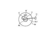
- FIG. 3 shows a state where the extra length portion 4A of the encoder lead wire 4 is sandwiched in the gap CL1 between the bottom 5a of the cover 5 and the electronic component 2.
- the extra length portion 4A is, for example, an intermediate portion in a range from one end of the encoder lead wire 4 to the other end.
- the extra length portion 4 ⁇ / b> A of the encoder lead wire 4 is between the bottom 5 a of the cover 5 and the electronic component 2.
- the electronic component 2 and the cylindrical portion 5b of the cover 5 are pushed out from the gap CL1 into a region 18 facing each other.
- the encoder 100-1 has a structure in which the cover 5 is rotatably fitted in the cylindrical portion 8a of the bracket 8, so that the encoder 100-1 is interposed between the bottom portion 5a of the cover 5 and the electronic component 2. Even when the extra length portion 4A of the lead wire 4 is sandwiched, the extra length portion 4A of the encoder lead wire 4 is moved to the region 18 where the electronic component 2 and the cylindrical portion 5b of the cover 5 face each other by rotating the cover 5. Can be made. Therefore, in consideration of the connection workability of the third connector 11, even when the encoder lead wire 4 has an extra length, the wire of the encoder lead wire 4 sandwiched between the bottom portion 5 a of the cover 5 and the electronic component 2.
- the axial length of the encoder 100-1 can be shortened by the wire diameter of the encoder lead wire 4.
- the encoder lead wire 4 is sandwiched in the gap CL.
- the second connector 10 is located near the opening 14 of the cover 5.
- the cover 5 is fitted into the cylindrical portion 8a of the bracket 8 while the electronic component 2 is disposed, the electronic component 2 is not disposed on the line connecting the second connector 10 and the opening 14. Therefore, when the cover 5 is fitted in this way, the encoder lead wire 4 can be prevented from being caught in the gap CL, and the extra length portion 4A of the encoder lead wire 4 is moved to the region 18 by rotating the cover 5. Can be made.
- the suppressing portion 6 is provided in the opening portion. Therefore, it is possible to suppress the encoder lead wire 4 from moving in the axial direction during the rotation of the cover 5 and being caught in the gap CL shown in FIG. 1, for example. Therefore, the rotation of the cover 5 becomes smooth, and the assembly workability of the encoder 100-1 is improved.
- the position of the suppressing portion 6 may be a position where the encoder lead wire 4 can suppress movement in the axial direction.
- the position of the first end surface 61 of the suppressing portion 6 shown in FIG. 2 in the axial direction is shown in FIG. It may be closer to the bracket 8 than the position of the second substrate surface 1b of the substrate 1 in the axial direction.
- the gap CL has a radial width between at least a part of the outer peripheral portion 1c of the substrate 1 facing the inner peripheral surface 5b1 of the cylindrical portion 5b and the inner peripheral surface 5b1 of the cylindrical portion 5b facing the region. equal.
- the encoder 100-1 according to the first embodiment may be configured such that the gap CL is smaller than the wire diameter of the encoder lead wire 4.
- the diameter of the cylindrical portion 5b of the cover 5 can be made smaller than when the gap CL is larger than the wire diameter of the encoder lead wire 4, and the radial dimension of the encoder 100-1 is made smaller.
- the gap CL is configured to be smaller than the wire diameter of the encoder lead wire 4, it is possible to prevent the extra length portion 4A of the encoder lead wire 4 from moving from the gap CL to the substrate fixing portion 3 side. it can. Therefore, it is possible to prevent the distance from the motor lead wire (not shown) wired near the board fixing portion 3 to the encoder lead wire 4 from being shortened. Therefore, it is difficult for noise from the motor lead wire to be superimposed on the encoder lead wire 4, and a decrease in detection accuracy of the rotational position of the rotor can be suppressed.
- FIG. 7 is a side view of a cover provided in the encoder according to the first modification of the first embodiment.
- the cover 5 shown in FIG. 7 is provided with a suppressing portion 6A instead of the suppressing portion 6 shown in FIG.
- the cover 5 shown in FIG. 7 has a width W1 from the first end surface 61 on the bottom 5a side of the suppressing portion 6A to the bottom 5a in the axial direction, and a width from the second substrate surface 1b to the bottom 5a of the substrate 1 in the axial direction. It is configured to be narrower than W2.
- FIG. 8 is a side view of a cover provided in the encoder according to the second modification of the first embodiment.
- the cover 5 shown in FIG. 8 is provided with the suppressing portion 6 ⁇ / b> A shown in FIG. 7, and further provided with a first protrusion 63.
- the first protrusion 63 is a protruding member that extends in the axial direction from the first end surface 61 of the suppressing portion 6 ⁇ / b> A in order to suppress the displacement of the encoder lead wire 4 in the rotational direction.
- the first protrusion 63 may be manufactured integrally with the suppressing portion 6A, or may be manufactured separately from the suppressing portion 6A and then attached to the suppressing portion 6A.
- the first protrusion 63 only needs to be able to suppress displacement of the encoder lead wire 4 in the rotational direction, and the shape of the first protrusion 63 is not limited to the shape shown in the example of the drawing.
- FIG. FIG. 9 is a perspective view of an encoder according to Embodiment 2 of the present invention.
- the substrate fixing unit 3A is used instead of the substrate fixing unit 3.
- the substrate fixing portion 3A is fixed to the cylindrical portion 8a of the bracket 8.
- a through-hole 31 is formed in the cylindrical portion 8 a of the bracket 8 so that the inside of the bracket 8 communicates with the space inside the cover 5.
- a concave portion 32 is formed in the substrate fixing portion 3A.
- the concave portion 32 is a space having a shape in which a part of the entire outer peripheral portion 3b of the substrate fixing portion 3A is recessed radially inward.
- the recess 32 extends in the rotation direction of the substrate fixing portion 3A and functions as a wiring path through which the motor lead wire 19 passes.
- the motor lead wire 19 is passed through the through hole 31 of the cylindrical portion 8a.
- One end of the motor lead wire 19 is connected to a motor (not shown), and the other end of the motor lead wire 19 is connected to the fourth connector 20.
- the fourth connector 20 is connected to the relay connector 12 shown in FIG.
- the substrate fixing portion 3A is provided with a protrusion similar to the protrusion 3c shown in FIG.
- the substrate 1 is first installed on the substrate fixing portion 3A, and then the first connector 9 is connected to the second connector 10. Furthermore, one end of the motor lead wire 19 is inserted into the through hole 31 of the cylindrical portion 8a.
- the third connector 11 and the fourth connector 20 are drawn from the inside of the cylindrical portion 5 b of the cover 5 to the outside of the cylindrical portion 5 b of the cover 5 through the opening 14.
- the motor lead wire 19 is wired in the concave portion 32 of the substrate fixing portion 3 ⁇ / b> A, and further wired at a position facing the second end face 62 side of the suppressing portion 6.
- the relay connector 12 is connected to the third connector 11 and the fourth connector 20. Thereafter, the cylindrical portion 5b of the cover 5 is fitted into the cylindrical portion 8a. Since the motor lead wire 19 is wired in the concave portion 32 of the substrate fixing portion 3A, the cylindrical portion 5b of the cover 5 does not interfere with the motor lead wire 19. Thereafter, the cover 5 is rotated, and finally the relay connector 12 is fixed to the cylindrical portion 5 b of the cover 5.
- the encoder 100-2 according to the second embodiment has a structure in which the cover 5 is rotatably fitted in the board fixing portion 3A, like the encoder 100-1 according to the first embodiment. Even when the extra length portion 4A of the encoder lead wire 4 is sandwiched between the electronic component 2, the encoder lead is placed in a region 18 where the electronic component 2 and the cylindrical portion 5b of the cover 5 face each other by rotating the cover 5. The extra length portion 4A of the line 4 can be moved.
- the motor lead wire 19 is wired at a position facing the second end face 62 side of the suppressing portion 6, the motor lead wire 19 is pivoted while the cover 5 is rotating. The movement in the direction can be suppressed. Therefore, the motor lead wire 19 can be prevented from moving in the axial direction and being caught in the gap CL shown in FIG. As a result, the rotation of the cover 5 becomes smooth, and the assembly workability of the encoder 100-2 is improved.
- the encoder lead wire 4 and the motor lead wire 19 are rotated while the cover 5 is rotated while the encoder lead wire 4 and the motor lead wire 19 are separated in the axial direction. Positional displacement in the axial direction can be suppressed. Therefore, the distance from the motor lead wire 19 to the encoder lead wire 4 becomes longer than when both the encoder lead wire 4 and the motor lead wire 19 are passed through, for example, the first end face 61 side of the suppressing portion 6. The noise from the motor lead wire 19 is not easily transmitted to the encoder lead wire 4. Therefore, it is possible to prevent the detection accuracy of the rotational position of the rotor from being lowered due to noise from the motor lead wire 19.
- FIG. 10 is a side view of a cover provided in the encoder according to the first modification of the second embodiment.
- the cover 5 shown in FIG. 10 is provided with a suppressing part 6B instead of the suppressing part 6 shown in FIG.
- the cover 5 shown in FIG. 10 has a width W3 from the second end surface 62 of the restraining portion 6B in the axial direction to the opening end 5c of the cover 5 such that the opening end of the cover 5 from the first substrate surface 1a of the substrate 1 in the axial direction. It is configured to be narrower than the width W4 up to 5c.
- the motor lead wire 19 can be prevented from being caught in the gap CL shown in FIG. 9 while the cover 5 is rotating. Therefore, for example, the rotation of the cover 5 is compared with the case where the position in the axial direction of the second end surface 62 of the suppressing portion 6B is closer to the bottom 5a side of the cover 5 than the position in the axial direction of the first substrate surface 1a of the substrate 1. As a result, the assembling workability of the encoder 100-2 is improved.
- the position in the axial direction of the second end surface 62 of the suppressing portion 6 ⁇ / b> B is closer to the bottom 5 a side of the cover 5 than the position in the axial direction of the first substrate surface 1 a of the substrate 1.
- substrate 1 can be extended. Accordingly, the axial distance between the motor lead wire 19 and the encoder lead wire 4 passing through the opening 14 is widened, and noise from the motor lead wire 19 is not easily transmitted to the encoder lead wire 4. As a result, it is possible to prevent the detection accuracy of the rotational position of the rotor from being lowered due to noise from the motor lead wire 19.
- cover 5 shown in FIG. 10 may be configured such that the width W1 is narrower than the width W2, similarly to the cover 5 shown in FIG. By comprising in this way, the effect similar to the cover 5 shown in FIG. 7 is acquired.
- FIG. 11 is a side view of a cover provided in the encoder according to the second modification of the second embodiment.
- the cover 5 shown in FIG. 11 is provided with the suppressing portion 6B of FIG. 10, and further provided with a first protrusion 63 and a second protrusion 64.
- the second protrusion 64 is a protruding member that extends in the axial direction from the second end face 62 of the suppressing portion 6 ⁇ / b> B in order to suppress displacement of the motor lead wire 19 in the rotational direction.
- the second protrusion 64 may be manufactured integrally with the suppressing portion 6B, or may be manufactured separately from the suppressing portion 6B and then attached to the suppressing portion 6B.
- the second protrusion 64 only needs to be able to suppress displacement of the motor lead wire 19 in the rotational direction, and the shape thereof is not limited to the shape shown in the drawing.
- the encoder lead wire 4 and the motor lead wire 19 is connected to the relay connector 12, whereby the servo amplifier is connected via the relay connector 12. And electrically connected. Accordingly, the length of the encoder lead wire 4 or the motor lead wire 19 can be shortened compared to the case where the relay connector 12 is not provided, and the work of passing the encoder lead wire 4 or the motor lead wire 19 through the opening 14 is facilitated. Thus, the assembly time of the encoders 100-1 and 100-2 is shortened.
- FIG. 12 is an external view of a servo motor according to Embodiment 3 of the present invention.
- a servo motor 200 shown in FIG. 12 is a motor used for a machine tool such as a machining center, an NC lathe, a laser machine, an electric discharge machine, or the like.
- Servo motor 200 includes motor 300 and encoder 100-1 according to the first embodiment.
- the motor 300 includes a case 301, a bracket 8 provided at an end of the case 301, a rotor (not shown) provided in the case 301, and a shaft 302 provided in the rotor.
- the servo motor 200 according to the third embodiment may use the encoder 100-2 according to the second embodiment instead of the encoder 100-1 according to the first embodiment.
- the encoder 100-1 of the first embodiment or the encoder 100-2 of the second embodiment is used, the axial length of the cylindrical portion 5b of the cover 5 is shortened, and the entire servo motor 200 is further updated. The size can be reduced.
- the configuration described in the above embodiment shows an example of the contents of the present invention, and can be combined with another known technique, and can be combined with other configurations without departing from the gist of the present invention. It is also possible to omit or change the part.
Landscapes
- Physics & Mathematics (AREA)
- General Physics & Mathematics (AREA)
- Transmission And Conversion Of Sensor Element Output (AREA)
Abstract
エンコーダ(100-1)は、基板(1)と、基板固定部(3)と、エンコーダリード線(4)とを備える。エンコーダ(100-1)は、第2基板面(1b)に設けられる電子部品(2)と、電子部品(2)と向き合う底部(5a)と、基板固定部(3)の外周部(3b)に回転可能に嵌め込まれると共に少なくともエンコーダリード線(4)が通る開口部(14)が形成される円筒部(5b)とを有する有底円筒状のカバー(5)とを備える。エンコーダ(100-1)は、開口部(14)の縁からカバー(5)の回転方向に沿った向きに伸び、基板固定部(3)の軸方向へのエンコーダリード線(4)の位置ずれを抑制する抑制部を備える。
Description
本発明は、ロータの回転位置を検出するエンコーダ及びサーボモータに関する。
特許文献1には、エンコーダの小型化を図るための技術が開示されている。特許文献1に開示されるエンコーダでは、エンコーダの小型化を図るため、カバーの内側面と基板の外周部との間の隙間に、絶縁部材が設けられている。カバーは、エンコーダ内部への塵埃、金属片などの浸入による絶縁性能の低下を抑制するため、電子部品が設けられる基板を覆う有底筒状に形成される導電性の部材である。絶縁部材を設けることにより、カバーの筒状部と基板との間の隙間を狭くしても、カバー内に設けられる配線部材とカバーの筒状部との間で生じる誘起電圧の上昇が抑制される。そのため、エンコーダの機能の低下を抑制しながら、エンコーダの径方向の大きさを小さくすることができる。
しかしながら、特許文献1に開示されるエンコーダでは、エンコーダリード線を、外部機器に接続する際の作業性を考慮して、エンコーダリード線に余長を持たせる必要がある。そのため、カバーの筒状部に形成される開口部にエンコーダリード線を通した後、カバーの筒状部をモータブラケットに近づけるように移動させるとき、エンコーダリード線の余長部分が、カバーの底部と向き合う位置に配置される電子部品と、カバーの底部との間の隙間に挟まる可能性がある。当該隙間にエンコーダリード線の余長部分が挟まった場合、カバーをモータブラケットへ確実に固定できない。従って、特許文献1に開示されるエンコーダでは、当該隙間にエンコーダリード線の余長部分が挟まらないようにするため、カバーの筒状部の軸方向長を、エンコーダリード線の線径分長くしなければならない。その結果、カバーの軸方向長が長くなり、エンコーダ全体の更なる小型化を図ることができないという課題があった。
本発明は、上記に鑑みてなされたものであって、カバーの内部に配線されるエンコーダリード線に余長部分が存在する場合でも小型化できるエンコーダを得ることを目的とする。
上述した課題を解決し、目的を達成するために、本発明のエンコーダは、第1基板面と第1基板面側とは逆側の第2基板面とを有する基板と、第1基板面が接する端部を有し、端部に基板が固定される円筒形状の基板固定部と、第2基板面と向き合う位置に設けられ、基板と電気的に接続され、ロータの回転位置を示す信号が伝送されるエンコーダリード線とを備える。エンコーダは、第2基板面に設けられる電子部品と、電子部品と向き合う底部と、基板固定部の外周部に回転可能に嵌め込まれると共に少なくともエンコーダリード線が通る開口部が形成される円筒部とを有する有底円筒状のカバーとを備える。エンコーダは、円筒部に設けられ、開口部の縁からカバーの回転方向に沿った向きに伸び、基板固定部の軸方向へのエンコーダリード線の位置ずれを抑制する抑制部を備えることを特徴とする。
本発明に係るエンコーダは、カバーの内部に設けられるエンコーダリード線に余長部分が存在する場合でも小型化できるという効果を奏する。
以下に、本発明の実施の形態に係るエンコーダ及びサーボモータを図面に基づいて詳細に説明する。なお、この実施の形態によりこの発明が限定されるものではない。
実施の形態1.
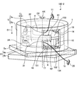
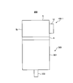
図1は本発明の実施の形態1に係るエンコーダの斜視図である。図2は図1に示すカバーに形成される開口部を示す図である。実施の形態1に係るエンコーダ100-1は、第1基板面1aと第1基板面1a側とは逆側の第2基板面1bとを有する基板1と、第2基板面1bに設けられる電子部品2と、第1基板面1aが接する端部3aを有し、端部3aに基板1が固定される円筒形状の基板固定部3と、第2基板面1bと向き合う位置に設けられ、基板1と電気的に接続され、ロータの回転位置を示す信号が伝送されるエンコーダリード線4とを備える。またエンコーダ100-1は、電子部品2と向き合う底部5aと、電子部品2と底部5aとの間の隙間がエンコーダリード線4の線径よりも小さくなるようにブラケット8の円筒部8aの外周部8a1に回転可能に嵌め込まれると共に少なくともエンコーダリード線4が通る開口部が形成される円筒部5bとを有する有底円筒状のカバー5と、円筒部5bに設けられ基板固定部3の軸方向へのエンコーダリード線4の位置ずれを抑制する抑制部6とを備える。
図1は本発明の実施の形態1に係るエンコーダの斜視図である。図2は図1に示すカバーに形成される開口部を示す図である。実施の形態1に係るエンコーダ100-1は、第1基板面1aと第1基板面1a側とは逆側の第2基板面1bとを有する基板1と、第2基板面1bに設けられる電子部品2と、第1基板面1aが接する端部3aを有し、端部3aに基板1が固定される円筒形状の基板固定部3と、第2基板面1bと向き合う位置に設けられ、基板1と電気的に接続され、ロータの回転位置を示す信号が伝送されるエンコーダリード線4とを備える。またエンコーダ100-1は、電子部品2と向き合う底部5aと、電子部品2と底部5aとの間の隙間がエンコーダリード線4の線径よりも小さくなるようにブラケット8の円筒部8aの外周部8a1に回転可能に嵌め込まれると共に少なくともエンコーダリード線4が通る開口部が形成される円筒部5bとを有する有底円筒状のカバー5と、円筒部5bに設けられ基板固定部3の軸方向へのエンコーダリード線4の位置ずれを抑制する抑制部6とを備える。
基板固定部3の径方向中心を通る中心軸AXが伸びる軸方向は、図1,2において符号D1で示される方向に等しい。カバー5の回転方向は、図1,2において符号D2で示される方向に等しい。
基板固定部3は、ねじ7を用いてブラケット8の円筒部8aの軸方向の端部へ着脱可能に固定される。ブラケット8は、不図示のモータケースの軸方向端部を閉塞する部材である板状の板部8bと、板部8bの基板固定部3側の端面に設けられる円筒部8aとにより構成される。円筒部8aは、絶縁性の材料を用いて板部8bと一体形成で製造したものでもよい。絶縁性の材料は、例えば、ポリブチレンテレフタレート、ポリフェニレンサルファイド、液晶ポリマーなどである。絶縁性の樹脂を用いてダイカストによりブラケット8を製造することによって、複雑な形状のブラケット8を安価に製造することができる。ブラケット8の円筒部8aの外径は、基板固定部3の外径よりも大きく、かつ、カバー5の円筒部5bの内径とほぼ等しい。また基板固定部3は、上記の絶縁性の材料を用いてブラケット8の円筒部8aとは別に製造された後にブラケット8へ取り付けられるが、絶縁性の材料を用いてブラケット8の円筒部8aと一体形成で製造したものでもよい。上記の絶縁性の樹脂を用いてダイカストにより基板固定部3を製造することによって、複雑な形状の基板固定部3を安価に製造することができる。なお本実施の形態では、基板固定部3がブラケット8の円筒部8aと別体で製造された場合の構成例について説明するが、基板固定部3がブラケット8の円筒部8aと一体成形で製造されている場合、一体成形で製造された基板固定部3及び円筒部8aの全体を、基板固定部3とし、又はブラケット8としてもよい。
基板固定部3には突起3cが形成される。突起3cは、基板固定部3の端部3aから軸方向に伸びる突形状の部材である。突起3cは、基板固定部3の端部3aと基板固定部3の外周部3bとが成す角部に形成される。基板固定部3の端部3aは、基板固定部3のブラケット8側とは逆側の端部である。図1には、説明を簡単化するため、1つの突起3cのみ示されるが、突起3cは複数設けられているものとし、複数の突起3cは、回転方向に互いに離れて配列される。図2では突起3cの図示が省略される。突起3cは、基板1の径方向外側に形成される窪み1dに嵌め込まれる。窪み1dは、基板1の外周部1cから基板1の径方向中心に向かって突形状の凹部である。突起3cと窪み1dとの間には、不図示の接着剤が設けられる。接着剤が設けられることによって、接着剤が設けられていない場合に比べて、基板1の窪み1dと突起3cとの接触面積が増加し、基板1が基板固定部3へ強固に固定される。
なお、突起3cの軸方向の長さは、基板1を保持できる長さであればよいが、例えば突起3cの先端が第2基板面1bよりも突き出るように、基板1の軸方向の厚みに相当する寸法よりも長くしてもよい。これにより、カバー5が回転したときに、例えば突起3cの径方向外側に配線される不図示のモータリード線が基板1に近づいて、モータリード線からのノイズが基板1に設けられる電子部品2、位置検出部などに与える影響を抑制できる。従って、突起3cを長くすることにより、ロータの回転位置の検出精度の低下を抑制できる。モータリード線は、不図示のモータへ電力を供給する配線である。
電子部品2は、例えば、位置検出部で検出されたロータの回転位置を示す信号を生成する信号生成回路、当該信号をエンコーダリード線4に出力する信号出力回路などを構成する部品でもよいし、エンコーダ100-1の外部に設けられるサーボアンプから供給される電力を位置検出部などへ供給する電源回路を構成する部品でもよい。電子部品2は、例えばIC(Integrated Circuit)、抵抗器、コイル、コンデンサなどである。電子部品2は1つでもよいし複数でもよい。図1及び図2では説明を簡単化するため、円筒状の構造体で電子部品2を模擬している。位置検出部は、不図示のロータの回転位置を検出する光学部品であり、例えば、基板固定部3の内側において、基板1の第1基板面1aに設けられる。第1基板面1aは、基板固定部3と向き合う基板1の端面である。
基板1の第2基板面1bには、電子部品2以外にも第1コネクタ9が設けられる。第2基板面1bは、カバー5の底部5aと向き合う基板1の端面である。第1コネクタ9は、基板1上のパターン配線を介して、電子部品2及び位置検出部と電気的に接続される。第1コネクタ9には第2コネクタ10が接続される。第2コネクタ10にはエンコーダリード線4の一端が接続される。第2コネクタ10が第1コネクタ9に接続されることにより、エンコーダリード線4が、電子部品2及び位置検出部と電気的に接続される。第1コネクタ9及び第2コネクタ10を用いることにより、エンコーダリード線4の基板1への接続が容易化される。なおエンコーダリード線4は、エンコーダリード線4が電子部品2と電気的に接続されればよく、第1コネクタ9及び第2コネクタ10を用いずに、例えば基板1上の配線パターンに直接半田付けによって接続されてもよい。なお図1及び図2では、説明を簡単化するため1本のエンコーダリード線4が示されるが、エンコーダリード線4は、複数の信号線で構成される信号群である。
エンコーダリード線4の他端には第3コネクタ11が接続される。第3コネクタ11は中継コネクタ12に接続される。中継コネクタ12は、エンコーダリード線4と不図示のモータリード線とを、エンコーダ100-1の外部に設けられるサーボアンプへ接続するためのコネクタである。中継コネクタ12には、サーボアンプから伸びるケーブル13が接続される。中継コネクタ12は、カバー5の円筒部5bに形成される開口部14を閉塞するように、カバー5の円筒部5bの外周部5dに固定される。開口部14の詳細は後述する。なお、中継コネクタ12には、第2コネクタ10以外にも、モータリード線に接続される。
カバー5は、エンコーダ100-1内部への塵埃、金属片などの浸入による絶縁性能の低下を抑制するための部品である。カバー5は、前述した絶縁性の材料を用いてダイカスト成形で筒状に形成したものでもよいし、銅合金、鋳鉄、鋼、鉄合金などの金属を用いてダイカスト成形で筒状に形成したものでもよい。金属でカバー5を製造することにより、カバー5の内側に存在する電子回路がカバー5の外部の磁界から保護される。
カバー5の円筒部5bの内周面5b1と、ブラケット8の円筒部8aの外周部8a1との間には、例えば不図示のOリングが設けられる。ブラケット8の円筒部8aにカバー5が嵌め込まれたとき、Oリングによって、ブラケット8の円筒部8aとカバー5との間の隙間が塞がれるため、カバー5の内部に塵埃、金属片などが浸入することを抑制できる。また図2に示すようにカバー5の開口端5c側には、カバー5の円筒部5bの外周部5dから径方向外側に伸びる鍔部5eが形成される。鍔部5eからブラケット8の板部8bに向けてねじ7がねじ込まれることによって、カバー5がブラケット8へ固定される。
カバー5の円筒部5bには開口部14が形成され、開口部14には抑制部6が設けられる。抑制部6は、カバー5の回転時におけるエンコーダリード線4の軸方向への位置ずれを抑制するための部材である。抑制部6は、カバー5と一体成形で製造されたものでもよいし、カバー5とは別に製造されたものでもよい。カバー5とは別に製造された抑制部6が用いられる場合、開口部14を形作る壁面15に、抑制部6が接着などで固定される。
抑制部6は、開口部14を形作る壁面15の内、カバー5の回転方向における第1壁面151から、第1壁面151と向き合う第2壁面152に向かって伸びる。すなわち、抑制部6は、開口部14の縁からカバー5の回転方向に沿った向きに伸びる。第1壁面151に抑制部6が設けられることにより、開口部14を形作る壁面15の内、カバー5の底部5a側に位置する第3壁面153と、第3壁面153と向き合う抑制部6の第1端面61との間には、窪み形状の第1空間16が形成される。第1空間16の軸方向の幅は、エンコーダリード線4の線径よりも広い。なおエンコーダリード線4は、前述したように、複数の信号線で構成されるため、エンコーダリード線4の線径は、複数の信号線を束ねた信号線群の太さとしてもよい。
また第1壁面151に抑制部6が設けられることにより、開口部14を形作る壁面15の内、カバー5の開口端5c側に位置する第4壁面154と、第4壁面154と向き合う抑制部6の第2端面62との間には、不図示のモータリード線が通る第2空間17が形成される。
エンコーダ100-1を組み立てる場合、まず、基板固定部3に基板1が設置され、その後、第1コネクタ9が第2コネクタ10に接続される。第1コネクタ9が第2コネクタ10に接続された後、エンコーダリード線4に設けられる第3コネクタ11は、カバー5の円筒部5bの内側から、開口部14を介して、カバー5の円筒部5bの外側へ引き出される。第3コネクタ11がカバー5の円筒部5bの外側へ引き出された後、第3コネクタ11に中継コネクタ12が接続される。
このように、第3コネクタ11の中継コネクタ12への接続作業性を考慮して、エンコーダリード線4には、余長を持たせる必要がある。但し、エンコーダリード線4に余長を持たせた場合、カバー5の円筒部5bがブラケット8の円筒部8aに嵌め込まれる際、エンコーダリード線4の余長部分が、カバー5の底部5aと電子部品2との間の隙間に挟まる可能性がある。実施の形態1に係るエンコーダ100-1は、カバー5が回転可能にブラケット8の円筒部8aに嵌め込まれる構造を有するため、カバー5の円筒部5bがブラケット8の円筒部8aに嵌め込まれたときに、カバー5の底部5aと電子部品2との間にエンコーダリード線4の余長部分が挟まった場合でも、カバー5の円筒部5bがブラケット8の板部8bに向かって押し付けられた状態で、カバー5を回転させることによって、カバー5内の空間の内、カバー5の底部5aと電子部品2との間の隙間以外の領域、すなわち電子部品2とカバー5の円筒部5bとが向き合う領域に、エンコーダリード線4の余長部分を移動させることができる。
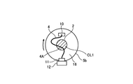
次にエンコーダ100-1の組立時にエンコーダリード線4の余長部分が移動する様子について説明する。図3は図1に示すエンコーダリード線の余長部分が移動する状態を示す第1図である。図4は図1に示すエンコーダリード線の余長部分が移動する状態を示す第2図である。図5は図1に示すエンコーダリード線の余長部分が移動する状態を示す第3図である。図6は図1に示すエンコーダリード線の余長部分が移動する状態を示す第4図である。
図3には、エンコーダリード線4の余長部分4Aが、カバー5の底部5aと電子部品2との間の隙間CL1に挟まった状態が示されている。余長部分4Aは、例えば、エンコーダリード線4の一端から他端までの範囲の内、中間部分である。
図4には、中継コネクタ12が固定されたカバー5の円筒部5bが、ブラケット8の板部8bに向かって押し付けられた状態で、時計回りに回転されたときのエンコーダリード線4の状態が示される。カバー5の円筒部5bの回転に伴い、エンコーダリード線4の余長部分4Aは、図1に示すカバー5の底部5aに擦れることによって、カバー5の底部5aと電子部品2との間の隙間CL1から、電子部品2とカバー5の円筒部5bとが向き合う領域18に向かって移動する。
図4に示す状態から、さらにカバー5が時計回りに回転されると、図5に示すように、エンコーダリード線4の余長部分4Aは、カバー5の底部5aと電子部品2との間の隙間CL1から、電子部品2とカバー5の円筒部5bとが向き合う領域18に押し出される。
図5に示す状態から、カバー5が反時計回りに回転されると、図6に示すように、エンコーダリード線4の余長部分4Aは、引き伸ばされて、電子部品2とカバー5の円筒部5bとが向き合う領域18に配線される。
このように実施の形態1に係るエンコーダ100-1は、カバー5が回転可能にブラケット8の円筒部8aに嵌め込まれる構造を有するため、カバー5の底部5aと電子部品2との間に、エンコーダリード線4の余長部分4Aが挟まった場合でも、カバー5を回転させることによって、電子部品2とカバー5の円筒部5bとが向き合う領域18に、エンコーダリード線4の余長部分4Aを移動させることができる。従って、第3コネクタ11の接続作業性を考慮して、エンコーダリード線4に余長を持たせている場合でも、カバー5の底部5aと電子部品2との間に挟まるエンコーダリード線4の線径分、カバー5の筒状部の軸方向長を長くする必要がない。その結果、エンコーダ100-1の軸方向の長さを、エンコーダリード線4の線径分、短くすることができる。なお、図3では、隙間CLにエンコーダリード線4が挟まっているが、例えば、エンコーダリード線4をカバー5の開口部14に通した後に、カバー5の開口部14の近くに第2コネクタ10が配置されるようにしながら、カバー5をブラケット8の円筒部8aに嵌め込んだ場合には、第2コネクタ10と開口部14とを結ぶ線上に、電子部品2が配置されなくなる。そのため、このようにカバー5が嵌め込まれた場合、隙間CLにエンコーダリード線4が挟まることを防止でき、さらに、カバー5を回転させることでエンコーダリード線4の余長部分4Aを領域18に這わせることができる。
また、実施の形態1に係るエンコーダ100-1では、開口部14に抑制部6が設けられている。そのため、カバー5の回転中に、エンコーダリード線4が軸方向に移動して、例えば図1に示す隙間CLにエンコーダリード線4が挟まることを抑制できる。従って、カバー5の回転が滑らかになり、エンコーダ100-1の組立作業性が向上する。なお抑制部6の位置は、エンコーダリード線4が軸方向に移動を抑制できる位置であればよく、例えば図2に示す抑制部6の第1端面61の軸方向における位置が、図1に示す基板1の第2基板面1bの軸方向における位置よりもブラケット8側でもよい。隙間CLは、円筒部5bの内周面5b1と向き合う基板1の外周部1cの内、少なくとも一部の領域と、当該領域に向き合う円筒部5bの内周面5b1との間の径方向幅に等しい。
また、実施の形態1に係るエンコーダ100-1は、隙間CLが、エンコーダリード線4の線径よりも小さくなるように構成してもよい。これにより、隙間CLがエンコーダリード線4の線径よりも大きい場合に比べて、カバー5の円筒部5bの直径を小さくすることができ、エンコーダ100-1の径方向の寸法が小さくなる。
また、隙間CLが、エンコーダリード線4の線径よりも小さくなるように構成されることによって、エンコーダリード線4の余長部分4Aが、隙間CLから基板固定部3側に移動することを抑制できる。そのため、基板固定部3の近くに配線される不図示のモータリード線からエンコーダリード線4までの距離が短くなることを抑制できる。従って、モータリード線からのノイズがエンコーダリード線4に重畳され難くなり、ロータの回転位置の検出精度の低下を抑制できる。
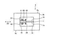
なおカバー5は以下のように構成してもよい。図7は実施の形態1の第1変形例に係るエンコーダに設けられるカバーの側面図である。図7に示されるカバー5には、図2に示される抑制部6の代わりに抑制部6Aが設けられる。図7に示されるカバー5は、軸方向における抑制部6Aの底部5a側の第1端面61から底部5aまでの幅W1が、軸方向における基板1の第2基板面1bから底部5aまでの幅W2よりも狭くなるように構成されている。このように構成されるカバー5を用いることにより、カバー5の回転中に、エンコーダリード線4が図1に示す隙間CLに挟まることを抑制できる。さらに、例えば図1に示す突起3cの先端が第2基板面1bよりも突き出でいる場合において、図1に示す突起3cの先端からカバー5の底部5aまでの幅をWと仮定したとき、WとW1とがW>W1の関係を満たすように、抑制部6A及び突起3cが構成されていれば、エンコーダリード線4が図1に示す突起3cに引っ掛かることを防止できる。従って、例えば抑制部6Aの第1端面61の軸方向における位置が、基板1の第2基板面1bの軸方向における位置よりもブラケット8側にある場合に比べて、カバー5の回転が滑らかになり、エンコーダ100-1の組立作業性が向上する。
図8は実施の形態1の第2変形例に係るエンコーダに設けられるカバーの側面図である。図8に示されるカバー5には、図7の抑制部6Aが設けられ、さらに第1突起63が設けられている。第1突起63は、エンコーダリード線4の回転方向への位置ずれを抑制するため、抑制部6Aの第1端面61から軸方向に伸びる突形状の部材である。第1突起63は、抑制部6Aと一体形成で製造したものでもよいし、抑制部6Aとは別に製作された後に抑制部6Aへ取り付けられたものでもよい。第1突起63は、エンコーダリード線4の回転方向への位置ずれを抑制できればよく、第1突起63の形状は図示例の形状に限定されない。
実施の形態2.
図9は本発明の実施の形態2に係るエンコーダの斜視図である。実施の形態2に係るエンコーダ100-2には、基板固定部3の代わりに基板固定部3Aが用いられる。基板固定部3Aは、ブラケット8の円筒部8aに固定される。ブラケット8の円筒部8aには、ブラケット8の内部とカバー5の内側の空間とを連通させる貫通孔31が形成される。また基板固定部3Aには凹部32が形成される。凹部32は、基板固定部3Aの外周部3b全体の内、一部の領域が径方向内側に窪む形状の空間である。凹部32は、基板固定部3Aの回転方向に伸び、モータリード線19が通る配線路として機能する。円筒部8aの貫通孔31にモータリード線19が通される。モータリード線19の一端には不図示のモータに接続され、モータリード線19の他端には第4コネクタ20が接続される。第4コネクタ20は図1に示す中継コネクタ12に接続される。なお図9では図示省略されているが、基板固定部3Aには、図1に示す突起3cと同様の突起が設けられているものとする。
図9は本発明の実施の形態2に係るエンコーダの斜視図である。実施の形態2に係るエンコーダ100-2には、基板固定部3の代わりに基板固定部3Aが用いられる。基板固定部3Aは、ブラケット8の円筒部8aに固定される。ブラケット8の円筒部8aには、ブラケット8の内部とカバー5の内側の空間とを連通させる貫通孔31が形成される。また基板固定部3Aには凹部32が形成される。凹部32は、基板固定部3Aの外周部3b全体の内、一部の領域が径方向内側に窪む形状の空間である。凹部32は、基板固定部3Aの回転方向に伸び、モータリード線19が通る配線路として機能する。円筒部8aの貫通孔31にモータリード線19が通される。モータリード線19の一端には不図示のモータに接続され、モータリード線19の他端には第4コネクタ20が接続される。第4コネクタ20は図1に示す中継コネクタ12に接続される。なお図9では図示省略されているが、基板固定部3Aには、図1に示す突起3cと同様の突起が設けられているものとする。
実施の形態2に係るエンコーダ100-2を組み立てる場合、まず基板固定部3Aに基板1が設置され、その後、第1コネクタ9が第2コネクタ10に接続される。さらにモータリード線19の一端が、円筒部8aの貫通孔31に挿入される。第3コネクタ11及び第4コネクタ20は、カバー5の円筒部5bの内側から、開口部14を介して、カバー5の円筒部5bの外側へ引き出される。このとき、モータリード線19は、基板固定部3Aの凹部32に配線され、さらに、抑制部6の第2端面62側と向き合う位置に配線される。第3コネクタ11及び第4コネクタ20がカバー5の円筒部5bの外側へ引き出された後、第3コネクタ11及び第4コネクタ20に中継コネクタ12が接続される。その後、カバー5の円筒部5bが円筒部8aに嵌め込まれる。モータリード線19は、基板固定部3Aの凹部32に配線されるため、カバー5の円筒部5bがモータリード線19に干渉することはない。その後カバー5を回転させ、最後に中継コネクタ12をカバー5の円筒部5bに固定する。
実施の形態2に係るエンコーダ100-2は、実施の形態1に係るエンコーダ100-1と同様に、カバー5が回転可能に基板固定部3Aに嵌め込まれる構造を有するため、カバー5の底部5aと電子部品2との間に、エンコーダリード線4の余長部分4Aが挟まった場合でも、カバー5を回転させることによって、電子部品2とカバー5の円筒部5bとが向き合う領域18に、エンコーダリード線4の余長部分4Aを移動させることができる。
また、実施の形態2に係るエンコーダ100-2では、モータリード線19が抑制部6の第2端面62側と向き合う位置に配線されるため、カバー5の回転中に、モータリード線19が軸方向に移動することを抑制できる。従って、モータリード線19が軸方向に移動して図9に示す隙間CLに挟まることを抑制できる。その結果、カバー5の回転が滑らかになり、エンコーダ100-2の組立作業性が向上する。
また実施の形態2に係るエンコーダ100-2によれば、エンコーダリード線4とモータリード線19とを軸方向に離しながら、カバー5の回転時におけるエンコーダリード線4及びモータリード線19のそれぞれの軸方向への位置ずれを抑制することができる。そのため、エンコーダリード線4及びモータリード線19の双方が、例えば抑制部6の第1端面61側に通されている場合に比べて、モータリード線19からエンコーダリード線4までの距離が長くなり、モータリード線19からのノイズがエンコーダリード線4に伝わり難くなる。従って、モータリード線19からのノイズによってロータの回転位置の検出精度が低下することを防ぐことができる。
なお実施の形態2に係るエンコーダ100-2のカバー5は以下のように構成してもよい。図10は実施の形態2の第1変形例に係るエンコーダに設けられるカバーの側面図である。図10に示されるカバー5には、図9に示される抑制部6の代わりに抑制部6Bが設けられる。図10に示されるカバー5は、軸方向における抑制部6Bの第2端面62からカバー5の開口端5cまでの幅W3が、軸方向における基板1の第1基板面1aからカバー5の開口端5cまでの幅W4よりも狭くなるように構成されている。このように構成されるカバー5を用いることにより、カバー5の回転中に、モータリード線19が図9に示す隙間CLに挟まることを抑制できる。従って、例えば抑制部6Bの第2端面62の軸方向における位置が、基板1の第1基板面1aの軸方向における位置よりもカバー5の底部5a側にある場合に比べて、カバー5の回転が滑らかになり、エンコーダ100-2の組立作業性が向上する。
また、図10に示すカバー5を用いることにより、例えば抑制部6Bの第2端面62の軸方向における位置が、基板1の第1基板面1aの軸方向における位置よりもカバー5の底部5a側にある場合に比べて、モータリード線19から基板1までの軸方向における距離を広げることができる。従って、開口部14を通るモータリード線19とエンコーダリード線4との軸方向の距離が広がり、モータリード線19からのノイズがエンコーダリード線4に伝わり難くなる。その結果、モータリード線19からのノイズによってロータの回転位置の検出精度が低下することを防ぐことができる。
なお、図10に示すカバー5は、図7に示されるカバー5と同様に、幅W1が幅W2よりも狭くなるように構成してもよい。このように構成することにより、図7に示すカバー5と同様の効果が得られる。
図11は実施の形態2の第2変形例に係るエンコーダに設けられるカバーの側面図である。図11に示されるカバー5には、図10の抑制部6Bが設けられ、さらに第1突起63及び第2突起64が設けられている。第2突起64は、モータリード線19の回転方向への位置ずれを抑制するため、抑制部6Bの第2端面62から軸方向に伸びる突形状の部材である。第2突起64は、抑制部6Bと一体形成で製造したものでもよいし、抑制部6Bとは別に製作された後に抑制部6Bへ取り付けられたものでもよい。第2突起64は、モータリード線19の回転方向への位置ずれを抑制できればよく、その形状は図示例の形状に限定されない。
実施の形態1,2のエンコーダ100-1,100-2では、エンコーダリード線4及びモータリード線19の少なくとも一方が、中継コネクタ12に接続されることによって、中継コネクタ12を介して、サーボアンプと電気的に接続される。従って、中継コネクタ12がない場合に比べて、エンコーダリード線4又はモータリード線19の配線長を短くすることができ、エンコーダリード線4又はモータリード線19を開口部14に通す作業が容易化され、エンコーダ100-1,100-2の組立時間が短縮される。
実施の形態3.
図12は本発明の実施の形態3に係るサーボモータの外観図である。図12に示すサーボモータ200は、例えばマシニングセンタ、NC旋盤、レ-ザ加工機、放電加工機などの工作機械に用いられるモータである。サーボモータ200は、モータ300と実施の形態1に係るエンコーダ100-1とを備える。モータ300は、ケース301と、ケース301の端部に設けられるブラケット8と、ケース301の内部に設けられ不図示のロータと、ロータに設けられるシャフト302とを備える。なお、実施の形態3に係るサーボモータ200には、実施の形態1に係るエンコーダ100-1の代わりに、実施の形態2に係るエンコーダ100-2を用いてもよい。実施の形態3では、実施の形態1のエンコーダ100-1又は実施の形態2のエンコーダ100-2が用いられるため、カバー5の円筒部5bの軸方向長が短くなり、サーボモータ200全体の更なる小型化を図ることができる。
図12は本発明の実施の形態3に係るサーボモータの外観図である。図12に示すサーボモータ200は、例えばマシニングセンタ、NC旋盤、レ-ザ加工機、放電加工機などの工作機械に用いられるモータである。サーボモータ200は、モータ300と実施の形態1に係るエンコーダ100-1とを備える。モータ300は、ケース301と、ケース301の端部に設けられるブラケット8と、ケース301の内部に設けられ不図示のロータと、ロータに設けられるシャフト302とを備える。なお、実施の形態3に係るサーボモータ200には、実施の形態1に係るエンコーダ100-1の代わりに、実施の形態2に係るエンコーダ100-2を用いてもよい。実施の形態3では、実施の形態1のエンコーダ100-1又は実施の形態2のエンコーダ100-2が用いられるため、カバー5の円筒部5bの軸方向長が短くなり、サーボモータ200全体の更なる小型化を図ることができる。
以上の実施の形態に示した構成は、本発明の内容の一例を示すものであり、別の公知の技術と組み合わせることも可能であるし、本発明の要旨を逸脱しない範囲で、構成の一部を省略、変更することも可能である。
1 基板、1a 第1基板面、1b 第2基板面、1c,3b,8a1 外周部、1d 窪み、2 電子部品、3,3A 基板固定部、3a 端部、3c 突起、4 エンコーダリード線、4A 余長部分、5 カバー、5a 底部、5b,8a 円筒部、5b1 内周面、5c 開口端、5e 鍔部、6,6A,6B 抑制部、7 ねじ、8 ブラケット、8b 板部、9 第1コネクタ、10 第2コネクタ、11 第3コネクタ、12 中継コネクタ、13 ケーブル、14 開口部、15 壁面、16 第1空間、17 第2空間、18 領域、19 モータリード線、20 第4コネクタ、31 貫通孔、32 凹部、61 第1端面、62 第2端面、63 第1突起、64 第2突起、100-1,100-2 エンコーダ、151 第1壁面、152 第2壁面、153 第3壁面、154 第4壁面、200 サーボモータ、300 モータ、301 ケース、302 シャフト。
Claims (10)
- 第1基板面と前記第1基板面側とは逆側の第2基板面とを有する基板と、
前記第1基板面が接する端部を有し、前記端部に前記基板が固定される円筒形状の基板固定部と、
前記第2基板面と向き合う位置に設けられ、前記基板と電気的に接続され、ロータの回転位置を示す信号が伝送されるエンコーダリード線と、
前記第2基板面に設けられる電子部品と、
前記電子部品と向き合う底部と、前記基板固定部の外周部に回転可能に嵌め込まれると共に少なくともエンコーダリード線が通る開口部が形成される円筒部とを有する有底円筒状のカバーと、
前記円筒部に設けられ、前記開口部の縁から前記カバーの回転方向に沿った向きに伸び、前記基板固定部の軸方向への前記エンコーダリード線の位置ずれを抑制する抑制部と、
を備えることを特徴とするエンコーダ。 - 前記円筒部の内周面と向き合う前記基板の外周部の内、少なくとも一部の領域と、当該領域に向き合う前記円筒部の内周面との間の隙間が、前記線径よりも小さいことを特徴とする請求項1に記載のエンコーダ。
- 前記軸方向における前記抑制部の前記底部側の第1端面から前記底部までの幅は、
前記軸方向における前記第2基板面から前記底部までの幅よりも狭いことを特徴とする請求項1又は2に記載のエンコーダ。 - 前記第1端面には、前記エンコーダリード線の前記回転方向への位置ずれを抑制する第1突起が設けられることを特徴とする請求項3に記載のエンコーダ。
- 前記開口部には、前記第1基板面と向き合う位置に設けられモータに電力を供給するモータリード線が通され、
前記抑制部は、前記エンコーダリード線と前記モータリード線とを前記軸方向に離しながら、前記カバーの回転時における前記エンコーダリード線及び前記モータリード線のそれぞれの前記軸方向への位置ずれを抑制することを特徴とする請求項1から4の何れか一項に記載のエンコーダ。 - 前記軸方向における前記抑制部の前記底部側の第1端面とは逆側の第2端面から前記円筒部の開口端までの幅は、
前記軸方向における前記第1基板面から前記開口端までの幅よりも狭いことを特徴とする請求項5に記載のエンコーダ。 - 前記第2端面には、前記モータリード線の前記回転方向への位置ずれを抑制する第2突起が設けられることを特徴とする請求項6に記載のエンコーダ。
- 前記開口部を閉塞するように前記円筒部の外周部に固定される中継コネクタを備え、
前記エンコーダリード線は前記中継コネクタに接続されることを特徴とする請求項1から7の何れか一項に記載のエンコーダ。 - 前記円筒部は、前記電子部品と前記底部との間の隙間が前記エンコーダリード線の線径より小さくなるように、前記基板固定部の外周部に回転可能に嵌め込まれることを特徴とする請求項1から8の何れか一項に記載のエンコーダ。
- 請求項1から9の何れか一項に記載のエンコーダと、モータとを備えることを特徴とするサーボモータ。
Priority Applications (5)
| Application Number | Priority Date | Filing Date | Title |
|---|---|---|---|
| CN201880010281.5A CN110832285B (zh) | 2018-06-13 | 2018-06-13 | 编码器的组装方法、编码器及伺服电动机 |
| JP2018563530A JP6479297B1 (ja) | 2018-06-13 | 2018-06-13 | エンコーダの組み立て方法、エンコーダ及びサーボモータ |
| KR1020197021878A KR102157817B1 (ko) | 2018-06-13 | 2018-06-13 | 엔코더의 조립 방법, 엔코더 및 서보 모터 |
| PCT/JP2018/022520 WO2019239508A1 (ja) | 2018-06-13 | 2018-06-13 | エンコーダ及びサーボモータ |
| TW108119420A TWI707124B (zh) | 2018-06-13 | 2019-06-05 | 編碼器的組裝方法、編碼器及伺服馬達 |
Applications Claiming Priority (1)
| Application Number | Priority Date | Filing Date | Title |
|---|---|---|---|
| PCT/JP2018/022520 WO2019239508A1 (ja) | 2018-06-13 | 2018-06-13 | エンコーダ及びサーボモータ |
Publications (1)
| Publication Number | Publication Date |
|---|---|
| WO2019239508A1 true WO2019239508A1 (ja) | 2019-12-19 |
Family
ID=65655824
Family Applications (1)
| Application Number | Title | Priority Date | Filing Date |
|---|---|---|---|
| PCT/JP2018/022520 Ceased WO2019239508A1 (ja) | 2018-06-13 | 2018-06-13 | エンコーダ及びサーボモータ |
Country Status (5)
| Country | Link |
|---|---|
| JP (1) | JP6479297B1 (ja) |
| KR (1) | KR102157817B1 (ja) |
| CN (1) | CN110832285B (ja) |
| TW (1) | TWI707124B (ja) |
| WO (1) | WO2019239508A1 (ja) |
Cited By (1)
| Publication number | Priority date | Publication date | Assignee | Title |
|---|---|---|---|---|
| JP2023018200A (ja) * | 2021-07-27 | 2023-02-08 | 日本電産サンキョー株式会社 | エンコーダおよびエンコーダ付きモータ |
Citations (3)
| Publication number | Priority date | Publication date | Assignee | Title |
|---|---|---|---|---|
| JP2008185557A (ja) * | 2007-01-31 | 2008-08-14 | Sendai Nikon:Kk | ロータリエンコーダの位置決めユニットと、これを有するロータリエンコーダ |
| JP2013187922A (ja) * | 2012-03-06 | 2013-09-19 | Nippon Densan Corp | ファンモータ |
| WO2017145613A1 (ja) * | 2016-02-23 | 2017-08-31 | 株式会社日立製作所 | アキシャルギャップ型回転電機 |
Family Cites Families (13)
| Publication number | Priority date | Publication date | Assignee | Title |
|---|---|---|---|---|
| US5763970A (en) * | 1997-03-03 | 1998-06-09 | Lexmark International, Inc. | Encoder system with cover mounted encoder |
| CN2828755Y (zh) * | 2005-10-25 | 2006-10-18 | 沈波 | 一种旋转编码器位移测量装置 |
| DE102006026543B4 (de) * | 2006-06-07 | 2010-02-04 | Vogt Electronic Components Gmbh | Lagegeber und zugehöriges Verfahren zum Erfassen einer Position eines Läufers einer Maschine |
| JP5195458B2 (ja) * | 2009-01-26 | 2013-05-08 | 日本精工株式会社 | 電動モータおよび該電動モータを備えた電動パワーステアリング装置 |
| CN103080698B (zh) * | 2010-09-03 | 2015-11-25 | Ntn株式会社 | 带旋转传感器的轴承 |
| CN103946675A (zh) | 2011-12-27 | 2014-07-23 | 株式会社安川电机 | 编码器及伺服电机 |
| JP2013187992A (ja) * | 2012-03-07 | 2013-09-19 | Jtekt Corp | 電動モータの制御装置及びこれを備えた車両用操舵装置 |
| JP6373079B2 (ja) * | 2014-06-13 | 2018-08-15 | 日本電産サンキョー株式会社 | センサ装置およびエンコーダ |
| JP6179476B2 (ja) * | 2014-07-31 | 2017-08-16 | 株式会社デンソー | 駆動装置、および、これを用いた電動パワーステアリング装置 |
| JP6582568B2 (ja) * | 2014-07-31 | 2019-10-02 | 株式会社デンソー | 駆動装置、および、これを用いた電動パワーステアリング装置 |
| CN205829399U (zh) * | 2016-06-17 | 2016-12-21 | 株式会社安川电机 | 一种编码器罩组件及马达装置 |
| CN206442248U (zh) * | 2017-01-22 | 2017-08-25 | 无锡市宏泰电机股份有限公司 | 一种用于电动机的编码器安装结构 |
| CN206724978U (zh) * | 2017-05-12 | 2017-12-08 | 华南理工大学 | 一种光栅旋转编码器 |
-
2018
- 2018-06-13 KR KR1020197021878A patent/KR102157817B1/ko active Active
- 2018-06-13 CN CN201880010281.5A patent/CN110832285B/zh active Active
- 2018-06-13 JP JP2018563530A patent/JP6479297B1/ja active Active
- 2018-06-13 WO PCT/JP2018/022520 patent/WO2019239508A1/ja not_active Ceased
-
2019
- 2019-06-05 TW TW108119420A patent/TWI707124B/zh active
Patent Citations (3)
| Publication number | Priority date | Publication date | Assignee | Title |
|---|---|---|---|---|
| JP2008185557A (ja) * | 2007-01-31 | 2008-08-14 | Sendai Nikon:Kk | ロータリエンコーダの位置決めユニットと、これを有するロータリエンコーダ |
| JP2013187922A (ja) * | 2012-03-06 | 2013-09-19 | Nippon Densan Corp | ファンモータ |
| WO2017145613A1 (ja) * | 2016-02-23 | 2017-08-31 | 株式会社日立製作所 | アキシャルギャップ型回転電機 |
Cited By (2)
| Publication number | Priority date | Publication date | Assignee | Title |
|---|---|---|---|---|
| JP2023018200A (ja) * | 2021-07-27 | 2023-02-08 | 日本電産サンキョー株式会社 | エンコーダおよびエンコーダ付きモータ |
| JP7689032B2 (ja) | 2021-07-27 | 2025-06-05 | ニデックインスツルメンツ株式会社 | エンコーダおよびエンコーダ付きモータ |
Also Published As
| Publication number | Publication date |
|---|---|
| KR102157817B1 (ko) | 2020-09-18 |
| TW202001195A (zh) | 2020-01-01 |
| TWI707124B (zh) | 2020-10-11 |
| CN110832285A (zh) | 2020-02-21 |
| JP6479297B1 (ja) | 2019-03-06 |
| CN110832285B (zh) | 2021-05-07 |
| JPWO2019239508A1 (ja) | 2020-06-25 |
| KR20200066586A (ko) | 2020-06-10 |
Similar Documents
| Publication | Publication Date | Title |
|---|---|---|
| US20190305650A1 (en) | Motor | |
| US20180115224A1 (en) | Motor | |
| CN110771016B (zh) | 电子设备 | |
| CN101416571A (zh) | 电子设备壳体 | |
| EP1367692B1 (en) | Stator structure for a rotation detector | |
| KR102060899B1 (ko) | 모터 | |
| US10686348B2 (en) | Electric actuator | |
| JP5523044B2 (ja) | 駆動制御装置、およびモータユニット | |
| JP2016207963A (ja) | 電子制御装置および駆動装置 | |
| JP6559370B1 (ja) | エンコーダおよびサーボモータ | |
| CN108696087A (zh) | 旋转变压器定子 | |
| JP6479297B1 (ja) | エンコーダの組み立て方法、エンコーダ及びサーボモータ | |
| JP6771655B2 (ja) | 電動パワーステアリング装置 | |
| JP2019180194A (ja) | モータ | |
| WO2021065451A1 (ja) | モータユニット | |
| KR20170112618A (ko) | 전자제어유닛의 차폐구조 | |
| TWI701424B (zh) | 編碼器及伺服馬達 | |
| US10875446B2 (en) | Actuator and head lamp comprising same | |
| CN113544946B (zh) | 电动机 | |
| US12228145B2 (en) | Motor and axial fan | |
| JP7828818B2 (ja) | ロータリエンコーダおよびトレランスリングを有するアセンブリ | |
| JP7651069B2 (ja) | 回路接続装置、及び回転電機装置 | |
| JP2019154178A (ja) | モータユニット | |
| JP2021156232A (ja) | 電動ポンプ | |
| WO2021065452A1 (ja) | モータユニット |
Legal Events
| Date | Code | Title | Description |
|---|---|---|---|
| ENP | Entry into the national phase |
Ref document number: 2018563530 Country of ref document: JP Kind code of ref document: A |
|
| 121 | Ep: the epo has been informed by wipo that ep was designated in this application |
Ref document number: 18922593 Country of ref document: EP Kind code of ref document: A1 |
|
| NENP | Non-entry into the national phase |
Ref country code: DE |
|
| 122 | Ep: pct application non-entry in european phase |
Ref document number: 18922593 Country of ref document: EP Kind code of ref document: A1 |