WO2019237254A1 - 柔性显示屏盖板及其制备方法和显示屏 - Google Patents
柔性显示屏盖板及其制备方法和显示屏 Download PDFInfo
- Publication number
- WO2019237254A1 WO2019237254A1 PCT/CN2018/090873 CN2018090873W WO2019237254A1 WO 2019237254 A1 WO2019237254 A1 WO 2019237254A1 CN 2018090873 W CN2018090873 W CN 2018090873W WO 2019237254 A1 WO2019237254 A1 WO 2019237254A1
- Authority
- WO
- WIPO (PCT)
- Prior art keywords
- adhesive layer
- flexible
- flexible display
- compound
- flexible substrate
- Prior art date
Links
Images


Classifications
-
- H—ELECTRICITY
- H04—ELECTRIC COMMUNICATION TECHNIQUE
- H04M—TELEPHONIC COMMUNICATION
- H04M1/00—Substation equipment, e.g. for use by subscribers
- H04M1/02—Constructional features of telephone sets
Definitions
- the present invention relates to the field of display technology, and in particular, to a flexible display cover plate, a method for manufacturing the same, and a display screen.
- the flexible display cover is set at the outermost part of the display.
- the existing flexible display cover usually uses a flexible substrate as a substrate, so that the flexible display cover has better bending resistance.
- the molecular structure of the substrate of the flexible display cover plate is liable to change, which causes the flexible display cover plate to turn yellow, thereby affecting the appearance and display effect of the display screen.
- the present invention provides a yellowing-resistant flexible display cover and a method for manufacturing the same.
- the present invention also provides a display screen using the flexible display cover.
- the present invention provides a flexible display cover, including:
- a hard coating layer is formed on a side of the adhesive layer away from the flexible substrate.
- the present invention also provides a method for preparing a flexible display cover, including the following steps:
- a hard coat layer is formed on a side of the adhesive layer remote from the flexible substrate.
- the present invention further provides a display screen, including the above-mentioned flexible display cover.
- the flexible display cover provided by the present invention, a preparation method thereof, and a display are provided with an adhesive layer containing an ultraviolet absorbent between a hard coating layer and a flexible substrate, thereby improving yellowing resistance of the flexible display cover And bending resistance.
- FIG. 1 is a schematic structural diagram of a flexible display cover provided by an embodiment of the present invention.
- FIG. 2 is a flowchart of a manufacturing method of the flexible display cover in FIG. 1.
- FIG. 3 is a stress distribution diagram of the flexible display cover in FIG. 1 in a bent state.
- FIG. 4 is a schematic structural diagram of a display screen provided by an embodiment of the present invention.
- FIG. 1 is a flexible display cover provided by an embodiment of the present invention.
- the flexible display cover 100 includes a flexible substrate 10, an adhesive layer 20 and a hard coat layer 30.
- the adhesive layer 20 is formed on the flexible substrate 10.
- the adhesive layer 20 contains an ultraviolet absorber.
- the hard coating layer 30 is formed on a side of the adhesive layer 20 remote from the flexible substrate 10.
- the flexible substrate 10 is made of a transparent material.
- the flexible substrate 10 is, for example, but not limited to a polyimide (PI) substrate, a colorless transparent polyimide (CPI) substrate, and polyethylene terephthalate (polyethylene terephthalate).
- PI polyimide
- CPI colorless transparent polyimide
- PET polyethylene terephthalate
- PA polyamide
- PC polycarbonate
- PES polyethersulfone
- PEN polyethylene naphthalate naphthalate
- PMMA polymethylmethacrylate
- COC Cyclo-olefin polymer
- COP Cyclo-olefin polymer
- the flexible substrate 10 has a flat bonding surface 11, and the adhesive layer 20 covers the bonding surface 11 of the flexible substrate 10 to prevent ultraviolet light from radiating to the flexible substrate 10.
- the flexible substrate 10 has an uneven bonding surface, which can effectively reduce the internal stress generated when the flexible display cover 100 is bent, so it will not cause the occurrence of staggered layers and prolong. The lifetime of the flexible display cover 100 and the adhesive layer 20 can adhere to the flexible substrate 10 more firmly.
- the adhesive layer 20 contains an ultraviolet absorbent, the problem of yellowing caused by the change of the molecular structure caused by the ultraviolet light shining on the flexible substrate 10 can be avoided, thereby improving the flexibility of the flexible display cover 100.
- the anti-yellowing performance further improves the appearance and display effect of the flexible display cover 100.
- the ultraviolet absorber is, for example, but is not limited to one or a combination of a salicylate compound, a benzophenone compound, a benzotriazole compound, a substituted acrylonitrile compound, or a triazine compound.
- the glue layer material is formed by doping organic heterocyclic compounds such as hydroxyphenyltriazine
- the chemical bonds of such organic heterocyclic compounds change from the ground state (low energy level) to the non-ground state (high energy level) after being irradiated with ultraviolet light. Ions are generated, and the process is a reversible chemical change; finally, the organic heterocyclic compound of hydroxyphenyltriazine can sufficiently absorb ultraviolet light, thereby blocking ultraviolet light from radiating to the flexible substrate 10, and the flexible substrate 10 can avoid absorbing ultraviolet light
- the yellowing is caused by the change of molecular structure caused by light.
- the ultraviolet absorber includes a triazine compound.
- the triazine compounds are, for example, but not limited to 2,4,6-tris (2′4′-dihydroxyphenyl) -1,3,5-triazine, 2,4,6-tris (2′- One or a combination of hydroxy 4′-n-butoxyphenyl).
- the adhesive layer 20 further includes a colloidal material with adhesive properties.
- the colloidal material is selected from various existing adhesives, and is not limited herein.
- the colloid material of the adhesive layer 20 is, for example, an optical adhesive, a pressure-sensitive adhesive, or an adhesive.
- the component of the adhesive layer 20 further includes, for example, but is not limited to one or a combination of an acrylate-based compound, a polyurethane-based compound, a silicone-based compound, or a rubber-based compound, so as to achieve adhesion of the adhesive layer 20 On the flexible substrate 10.
- the thickness of the adhesive layer 20 is approximately 0.025 mm to 0.3 mm.
- the ultraviolet absorber accounts for 0.1% -20% of the weight of the adhesive layer 20.
- the adhesive layer 20 further includes glass microbeads dispersed in the colloidal material.
- the ultraviolet light passes through the colloidal material, it will be reflected multiple times by the glass beads inside the colloidal material, thereby changing and extending the propagation path of the ultraviolet light in the colloidal material, and the ultraviolet absorber contained in the colloidal material can fully absorb the ultraviolet light. Therefore, the transmittance of the ultraviolet laser is reduced, and the problem of yellowing caused by the change of the molecular structure of the flexible substrate due to ultraviolet irradiation is avoided.
- the glass microbeads are made of a reflective material or the surface of the glass microbeads is coated with a reflective material.
- the reflective material is, for example, but is not limited to, silver, aluminum, or other metallic materials.
- the material of the hard coating layer 30 is different from the material of the adhesive layer 20, so that the adhesive layer 20 can absorb the stress of the hard coating layer 30 in a bent state, and improve the rigidity and scratch resistance of the flexible display cover 100. performance.
- the dielectric constant of the hard coat layer 30 is different from the dielectric constant of the adhesive layer 20.
- the stress absorption of the adhesive layer 20 reduces the stress of the hard coating layer 30 and reduces the transmittance of ultraviolet light.
- the hard coat layer 30 is made of a transparent material.
- the hard coat layer 30 includes organic compounds such as acrylates and polyethylene terephthalates, and inorganic compounds such as titanium nitride, titanium carbonitride, and tungsten sulfide.
- the thickness of the hard coating layer 30 is approximately 5 ⁇ m to 50 ⁇ m.
- FIG. 2 it is a flowchart of a method for manufacturing a flexible display cover plate according to an embodiment of the present invention.
- the method for preparing the flexible display cover 100 includes the following steps:
- a hard coating is formed on a side of the adhesive layer away from the flexible substrate.
- forming an adhesive layer 20 on the flexible substrate 10 specifically includes:
- the liquid glue is coated on the flexible substrate 10 and cured, so that the glue layer 20 is attached to the flexible substrate 10.
- the mixed solution is evenly coated on the bonding surface 11 of the flexible substrate 10, so that the prepared adhesive layer 20 covers the flexible substrate 10, so that the adhesive layer 20 can absorb ultraviolet light, thereby preventing the ultraviolet light from irradiating the flexible substrate.
- the material 10 causes the problem of yellowing caused by the change of the molecular structure, thereby improving the yellowing resistance of the flexible display cover 100.
- the ultraviolet absorber is, for example, but is not limited to one or a combination of a salicylate compound, a benzophenone compound, a benzotriazole compound, a substituted acrylonitrile compound, or a triazine compound.
- the ultraviolet absorber includes a triazine compound.
- Triazine compounds are, for example, but are not limited to 2,4,6-tris (2′4′-dihydroxyphenyl) -1,3,5-triazine, 2,4,6-tris (2′- One or a combination of hydroxy 4′-n-butoxyphenyl).
- the mixed solution further includes a colloidal material and glass microbeads.
- Glass beads are made of reflective material or the surface of glass beads is coated with reflective material.
- the reflective material is, for example, but is not limited to, silver, aluminum, or other metallic materials.
- the colloidal material is a colloidal material having adhesive properties.
- the colloidal material is selected from various existing adhesives, and is not limited herein.
- the colloid material of the adhesive layer 20 is, for example, an optical adhesive, a pressure-sensitive adhesive, or an adhesive.
- the component of the adhesive layer 20 further includes, for example, but is not limited to one or a combination of an acrylate-based compound, a polyurethane-based compound, a silicone-based compound, or a rubber-based compound, so as to achieve adhesion of the adhesive layer 20 On the flexible substrate 10.
- forming the adhesive layer 20 on the flexible substrate 10 specifically includes:
- the adhesive layer 20 and the flexible base material 10 are laminated, pressed and heated to perform bonding, so that the adhesive layer 20 is adhered to the flexible base material 10.
- the adhesive layer 20 covers the bonding surface 11 of the flexible substrate 10 to avoid irradiation of ultraviolet light.
- the hard coating layer 30 may also be formed on the adhesive layer 20 by coating or laminating to obtain a flexible display cover 100.
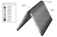
- FIG. 3 is a stress distribution diagram of the flexible display cover in a bent state according to an embodiment of the present invention.
- the flexible display cover 100 has a bent section 101 and a non-bent section 102.
- the bending section 101 receives the greatest stress.
- the adhesive layer 20 is a viscoelastic body, that is, the adhesive layer 20 has viscosity and elasticity.
- the adhesive layer 20 can effectively absorb the stress of the bending section 101.
- the reduction of the stress on the hard coating layer 30 in the bending section 101 can correspondingly improve the bending resistance of the hard coating layer 30. Therefore, an adhesive layer 20 is provided between the flexible substrate 10 and the hard coating layer 30, thereby The stress of the flexible substrate 10 and the hard coating layer 30 can be absorbed, thereby improving the bending performance of the hard coating layer 30.
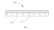
- FIG. 4 is a schematic structural diagram of a display screen according to an embodiment of the present invention.
- the display screen 1000 includes the flexible display cover 100 and the touch assembly 200 described above.
- the flexible display cover 100 is formed above the touch module 200.
- the display screen 1000 is, for example, a flexible touch screen or a flexible display screen.
- Flexible display screens are, for example, but are not limited to liquid crystal display (LCD) panels, quantum dot display (Emitting Diodes, QLED) panels, E-paper display (EPD), and touch panels ), Flexible solar cell (Page View, PV) panels, radio frequency tags (Radio Frequency Identification, RFID) and other products or components with display functions.
- the flexible display cover provided by the present invention, a preparation method thereof, and a display are provided with an adhesive layer containing an ultraviolet absorbent between a hard coating layer and a flexible substrate, thereby improving yellowing resistance of the flexible display cover. And bending resistance.
Abstract
本发明提供了一种柔性显示屏盖板及其制备方法和显示屏。所述柔性显示屏盖板包括柔性基材、胶层和硬涂层。所述胶层形成在所述柔性基材上。所述胶层中包含有紫外线吸收剂。所述硬涂层形成在所述胶层远离所述柔性基材的一侧。本发明提供的柔性显示屏盖板及其制备方法和显示屏,通过在硬涂层和柔性基材之间增设包含有紫外线吸收剂的胶层,从而提高了柔性显示屏盖板的抗黄化及耐弯折性能。
Description
本发明涉及显示技术领域,尤其涉及一种柔性显示屏盖板及其制备方法和显示屏。
柔性显示屏盖板作为显示屏主要组成部分之一,设置在显示屏的最外部。现有的柔性显示屏盖板通常采用柔性基材作为衬底,以使柔性显示屏盖板具有较好的耐弯折性能。然而,在紫外光照射后,柔性显示屏盖板的基材分子结构易发生改变,从而导致柔性显示屏盖板发黄,进而影响显示屏的外观及显示效果。
发明内容
鉴于现有技术中存在的上述问题,本发明提供一种抗黄化的柔性显示屏盖板及其制备方法。
另外,本发明还提供一种应用所述柔性显示屏盖板的显示屏。
为了实现上述目的,本发明实施方式提供如下技术方案:
第一方面,本发明提供一种柔性显示屏盖板,包括:
柔性基材;
胶层,形成在所述柔性基材上,所述胶层中包含有紫外线吸收剂;及
硬涂层,形成在所述胶层远离所述柔性基材的一侧。
第二方面,本发明还提供了一种柔性显示屏盖板的制备方法,包括如下步骤:
提供柔性基材;
在所述柔性基材上形成胶层,所述胶层中包含有紫外线吸收剂;及
在所述胶层远离所述柔性基材的一侧形成硬涂层。
第三方面,本发明还提供了一种显示屏,包括上述柔性显示屏盖板。
本发明提供的柔性显示屏盖板及其制备方法和显示屏,通过在硬涂层和柔性基材之间增设包含有紫外线吸收剂的胶层,从而提高了柔性显示屏盖板的抗黄化及耐弯折性能。
为了更清楚地说明本发明实施例或现有技术中的技术方案,下面将对实施例或现有技术描述中所需要使用的附图作简单地介绍,显而易见地,下面描述中的附图仅仅是本发明的一些实施例,对于本领域普通技术人员来讲,在不付出创造性劳动的前提下,还可以根据这些附图获得其他的附图。
图1是本发明实施例提供的柔性显示屏盖板的结构示意图。
图2是图1中的柔性显示屏盖板的制备方法的流程图。
图3是图1中的柔性显示盖板处于弯折状态的应力分布图。
图4是本发明实施例提供的显示屏的结构示意图。
下面将结合本发明实施例中的附图,对本发明实施例中的技术方案进行清楚、完整地描述,显然,所描述的实施例仅仅是本发明一部分实施例,而不是全部的实施例。基于本发明中的实施例,本领域普通技术人员在没有做出创造性劳动前提下所获得的所有其他实施例,都属于本发明保护的范围。
可以理解,这里所用的术语仅是为了描述特定实施例,并非要限制本发明。在这里使用时,除非上下文另有明确表述,否则单数形式“一”和“该”也旨在包括复数形式。进一步地,当在本说明书中使用时,术语“包括”和/或“包含”表明所述特征、整体、步骤、元件和/或组件的存在,但不排除一个或多个其他特征、整体、步骤、元件、组件和/或其组合的存在或增加。说明书后续描述为实施本发明的较佳实施方式,然所述描述乃以说明本发明的一般原则为目的, 并非用以限定本发明的范围。本发明的保护范围当视所附权利要求所界定者为准。
请参阅图1,为本发明实施例提供的一种柔性显示屏盖板。柔性显示屏盖板100包括柔性基材10、胶层20和硬涂层30。胶层20形成在柔性基材10上。胶层20中包含有紫外线吸收剂。硬涂层30形成在胶层20远离柔性基材10的一侧。
柔性基材10由透明材料制成。柔性基材10例如是,但不局限于聚酰亚胺(Polyimide,PI)基材、无色透明聚酰亚胺(Colorless Polyimide,CPI)基材、聚对苯二甲酸乙二醇酯(polyethylene terephthalate,PET)基材、聚酰胺(polyamide,PA)基材、聚碳酸酯(polycarbonate,PC)基材、聚苯醚砜(polyethersulfone,PES)基材、聚萘二甲酸乙二醇酯(polyethylene naphthalate,PEN)基材、聚甲基丙烯酸甲酯(polymethylmethacrylate,PMMA)基材、环烯烃共聚物(cycloolefin copolymer,COC)基材、环烯烃聚合物(Cyclo-olefin polymer,COP)基材中的一种。
在本实施例中,柔性基材10具有平坦的贴合面11,胶层20覆盖柔性基材10的贴合面11,以避免紫外光线照射至柔性基材10。可以理解的,在其他实施例中,柔性基材10具有凹凸不平的贴合面,从而能够有效消减柔性显示屏盖板100在弯曲时产生的内应力,因此不会造成错层的出现,延长柔性显示屏盖板100的寿命,且胶层20能够更牢固地粘附于柔性基材10上。
可以理解的,由于胶层20中包含有紫外线吸收剂,因此可避免紫外光线照射至柔性基材10上而导致分子结构发生改变而造成黄化的问题,从而提高了柔性显示屏盖板100的抗黄化性能,进而提高了柔性显示屏盖板100的美观和显示效果。其中,紫外线吸收剂例如是,但不局限于水杨酸酯类化合物、苯酮类化合物、苯并三唑类化合物、取代丙烯腈类化合物或三嗪类化合物的一种或其组合。
可以理解的,由于胶层材料掺杂羟基苯三嗪之类的有机杂环化合物形成, 此类有机杂环化合物的化学键经紫外光照射后从基态(低能级)变成非基态(高能级)并产生离子,且该过程是一个可逆化学变化;最终羟基苯三嗪的有机杂环化合物可充分吸收紫外光,从而阻隔紫外光照射至柔性基材10,进而柔性基材10可避免因吸收紫外光线而导致的分子结构发生改变而造成黄化的问题。
优选的,在本实施例中,紫外线吸收剂包括三嗪类化合物。三嗪类化合物例如是,但不局限于2,4,6-三(2′4′-二羟基苯基)-1,3,5-三嗪、2,4,6-三(2′-羟基4′-正丁氧基苯基)中的一种或其组合。
所述胶层20还包含有具有黏合特性的胶体材料。胶体材料选自现有的各种黏合胶,此处不做限定。具体的,在本实施例中,胶层20的胶体材料例如是光学胶、压敏胶或胶黏剂。进一步的,胶层20的成分还包含有例如是,但不局限于丙烯酸酯系化合物、聚氨酯类化合物、硅胶系化合物或橡胶系化合物中的一种或其组合,从而实现将胶层20粘附于柔性基材10上。
在本实施例中,胶层20的厚度大致为0.025mm至0.3mm。在本实施例中,紫外线吸收剂占胶层20重量的0.1%-20%。
进一步的,胶层20还包括分散于胶体材料内的玻璃微珠。紫外光线在通过胶体材料时会在胶体材料内部经过玻璃微珠多次反射,从而改变且延长了紫外光线在胶体材料内的传播路径,进而胶体材料内含有的紫外线吸收剂可充分吸收紫外光线,因此降低了紫外激光的透过率,且避免柔性基材的分子结构因紫外线照射而发生变化造成黄化的问题。其中,玻璃微珠由反射材料制成或是在玻璃微珠的表面涂覆反射材料。反射材料例如是,但不局限于银、铝或其他金属材料。
可以理解的,硬涂层30的材料不同于胶层20的材料,以使胶层20能够吸收硬涂层30处于弯折状态的应力,且提高柔性显示屏盖板100的硬度和耐摩防刮性能。在本实施例中,硬涂层30的介电常数不同于胶层20的介电常数。通过胶层20应力吸收作用以减小硬涂层30的应力,并且降低紫外光线的透过率。在本实施例中,硬涂层30由透明材料制成。硬涂层30包括丙烯酸酯类、 聚对苯二甲酸乙二醇酯类等有机化合物,以及氮化钛、碳氮铝钛化合物、硫化钨等无机化合物。
可以理解的,硬涂层30的厚度越小,柔性显示屏盖板100的耐弯折性能越好,然而,硬涂层的厚度越小,柔性显示屏盖板100的硬度、耐磨耐刮性能越差。因此,为了确保柔性显示屏盖板100的耐弯折性能、硬度、及耐刮擦性能均衡,硬涂层30的厚度大致为5μm至50μm。
如图2所示,为本发明实施例提供的柔性显示屏盖板的制备方法的流程图。柔性显示屏盖板100的制备方法,包括如下步骤:
S201、提供柔性基材;
S203、在柔性基材上形成胶层,胶层中包含有紫外线吸收剂;及
S205、在胶层远离柔性基材的一侧形成硬涂层。
请一并参阅图1和图2,在一实施例中,在柔性基材10上形成胶层20,具体包括:
配置包含有紫外线吸收剂的液态胶;
将液态胶涂覆在柔性基材10上,并固化,以使胶层20贴附于柔性基材10。
其中,混合溶液均匀地涂覆于柔性基材10的贴合面11,以使制得的胶层20覆盖柔性基材10,从而胶层20可吸收紫外光线,从而避免紫外光线照射至柔性基材10导致分子结构发生变化而造成黄化的问题,进而提高了柔性显示屏盖板100的抗黄化性能。紫外线吸收剂例如是,但不局限于水杨酸酯类化合物、苯酮类化合物、苯并三唑类化合物、取代丙烯腈类化合物或三嗪类化合物的一种或其组合。
优选的,在本实施例中,紫外线吸收剂包括三嗪类化合物。三嗪类化合物例如是,但不局限于2,4,6-三(2′4′-二羟基苯基)-1,3,5-三嗪、2,4,6-三(2′-羟基4′-正丁氧基苯基)中的一种或其组合。
所述混合溶液中还包含有胶体材料和玻璃微珠。玻璃微珠由反射材料制成 或是在玻璃微珠的表面涂覆反射材料。反射材料例如是,但不局限于银、铝或其他金属材料。胶体材料为具有黏合特性的胶体材料。胶体材料选自现有的各种黏合胶,此处不做限定。具体的,在本实施例中,胶层20的胶体材料例如是光学胶、压敏胶或胶黏剂。进一步的,胶层20的成分还包含有例如是,但不局限于丙烯酸酯系化合物、聚氨酯类化合物、硅胶系化合物或橡胶系化合物中的一种或其组合,从而实现将胶层20粘附于柔性基材10上。
在另一实施例中,在柔性基材10上形成胶层20,具体包括:
预先制备包含有紫外线吸收剂的固态的胶层20;
将胶层20与柔性基材10进行层叠、加压/加热来进行贴合,以使胶层20贴附于柔性基材10。
其中,胶层20覆盖柔性基材10的贴合面11,以避免紫外光线的照射。硬涂层30也可通过涂覆或贴合的方式形成在胶层20上,以制得柔性显示屏盖板100。
可以理解的,上述柔性基材10、胶层20及硬涂层30的材料组成、结构及用量比例均可参阅上述实施例中的柔性显示屏盖板100的结构描述,在此不再赘述。
请参看图3,为本发明实施例提供的柔性显示盖板处于弯折状态的应力分布图。如图3所示,柔性显示屏盖板100具有弯折段101和非弯折段102。柔性显示屏盖板100处于弯曲状态时,弯折段101受到的应力最大。可以理解的,在本实施例中,胶层20是一种黏弹性体,也即胶层20具有黏性和弹性。通过胶层20可有效吸收弯折段101的应力。进一步的,硬涂层30在弯折段101承受的应力的减小可对应提高硬涂层30的耐弯折性能,因此在柔性基材10和硬涂层30之间设置胶层20,从而可吸收柔性基材10和硬涂层30的应力,进而提高了硬涂层30的弯折性能。
请参看图4,为本发明实施例提供的显示屏的结构示意图。显示屏1000包括上述柔性显示屏盖板100和触摸组件200。柔性显示屏盖板100形成在触 摸组件200的上方。
在本实施例中,显示屏1000例如是柔性触摸屏或柔性显示屏。柔性显示屏例如是,但不局限于液晶显示(Liquid Crystal Display,LCD)面板、量子点显示(Quantum Dot Light Emitting Diodes,QLED)面板、电子纸(E-paper Display,EPD)、触摸屏(Touch panel)、柔性太阳能电池(Page View,PV)板、射频标签(Radio Frequency Identification,RFID)等具有显示功能的产品或部件。
本发明提供的柔性显示屏盖板及其制备方法和显示屏,通过在硬涂层和柔性基材之间增设包含有紫外线吸收剂的胶层,从而提高了柔性显示屏盖板的抗黄化及耐弯折性能。
以上所述的实施方式,并不构成对该技术方案保护范围的限定。任何在上述实施方式的原则之内所作的修改、等同替换和改进等,均应包含在该技术方案的保护范围之内。
Claims (15)
- 一种柔性显示屏盖板,其特征在于,包括:柔性基材;胶层,形成在所述柔性基材上,所述胶层中包含有紫外线吸收剂;及硬涂层,形成在所述胶层远离所述柔性基材的一侧。
- 如权利要求1所述的柔性显示屏盖板,其特征在于,所述紫外线吸收剂包括水杨酸酯类化合物、二苯甲酮类化合物、苯并三唑类化合物、取代丙烯腈类化合物或三嗪类化合物中的一种或其组合。
- 如权利要求2所述的柔性显示屏盖板,其特征在于,所述三嗪类化合物包括2,4,6-三(2′4′-二羟基苯基)-1,3,5-三嗪、2,4,6-三(2′-羟基4′-正丁氧基苯基)中的一种或其组合。
- 如权利要求1所述的柔性显示屏盖板,其特征在于,所述胶层材料为光学胶、压敏胶或胶黏剂。
- 如权利要求1所述的柔性显示屏盖板,其特征在于,所述胶层成分还包含有丙烯酸酯系化合物、聚氨酯类化合物、硅胶系化合物或橡胶系化合物中的一种或其组合。
- 如权利要求1所述的柔性显示屏盖板,其特征在于,所述柔性基材为聚酰亚胺基材、无色透明聚酰亚胺基材、聚对苯二甲酸乙二醇酯基材、聚酰胺基材、聚碳酸酯基材、聚苯醚砜基材、聚萘二甲酸乙二醇酯基材、聚甲基丙烯酸甲酯基材、环烯烃共聚物基材或环烯烃聚合物基材。
- 如权利要求1所述的柔性显示屏盖板,其特征在于,所述胶层的厚度为0.025mm至0.3mm。
- 如权利要求1所述的柔性显示屏盖板,其特征在于,所述硬涂层的厚度为5μm至50μm。
- 如权利要求1所述的柔性显示屏盖板,其特征在于,所述胶层的介电常数不同于所述硬涂层的介电常数。
- 一种柔性显示屏盖板的制备方法,包括如下步骤:提供柔性基材;在所述柔性基材上形成胶层,所述胶层中包含有紫外线吸收剂;及在所述胶层远离所述柔性基材的一侧形成硬涂层。
- 如权利要求10所述的柔性显示屏盖板的制备方法,其特征在于,在柔性基材上形成胶层,具体包括:配置包含有所述紫外线吸收剂的液态胶;将所述液态胶涂覆在所述柔性基材上,并固化,以使所述胶层形成于所述柔性基材。
- 如权利要求10所述的柔性显示屏盖板的制备方法,其特征在于,在柔性基材上形成胶层,具体包括:预先制备包含有所述紫外线吸收剂的固态的所述胶层;将所述胶层与所述柔性基材进行层叠并贴合,以使所述胶层贴附于所述柔性基材。
- 如权利要求10所述的柔性显示屏盖板的制备方法,其特征在于,所述紫外线吸收剂包括水杨酸酯类化合物、二苯甲酮类化合物、苯并三唑类化合物、取代丙烯腈类化合物或三嗪类化合物中的一种或其组合。
- 如权利要求10所述的柔性显示屏盖板的制备方法,其特征在于,所述三嗪类化合物包括2,4,6-三(2′4′-二羟基苯基)-1,3,5-三嗪、2,4,6-三(2′-羟基4′-正丁氧基苯基)中的一种或其组合。
- 一种显示屏,包括如权利要求1至9任意一项所述的柔性屏盖板。
Priority Applications (2)
| Application Number | Priority Date | Filing Date | Title |
|---|---|---|---|
| PCT/CN2018/090873 WO2019237254A1 (zh) | 2018-06-12 | 2018-06-12 | 柔性显示屏盖板及其制备方法和显示屏 |
| CN201880093886.5A CN112470447A (zh) | 2018-06-12 | 2018-06-12 | 柔性显示屏盖板及其制备方法和显示屏 |
Applications Claiming Priority (1)
| Application Number | Priority Date | Filing Date | Title |
|---|---|---|---|
| PCT/CN2018/090873 WO2019237254A1 (zh) | 2018-06-12 | 2018-06-12 | 柔性显示屏盖板及其制备方法和显示屏 |
Publications (1)
| Publication Number | Publication Date |
|---|---|
| WO2019237254A1 true WO2019237254A1 (zh) | 2019-12-19 |
Family
ID=68841815
Family Applications (1)
| Application Number | Title | Priority Date | Filing Date |
|---|---|---|---|
| PCT/CN2018/090873 WO2019237254A1 (zh) | 2018-06-12 | 2018-06-12 | 柔性显示屏盖板及其制备方法和显示屏 |
Country Status (2)
| Country | Link |
|---|---|
| CN (1) | CN112470447A (zh) |
| WO (1) | WO2019237254A1 (zh) |
Cited By (4)
| Publication number | Priority date | Publication date | Assignee | Title |
|---|---|---|---|---|
| CN111136960A (zh) * | 2019-12-27 | 2020-05-12 | 武汉华星光电半导体显示技术有限公司 | 一种盖板及显示装置 |
| US10985344B2 (en) | 2017-10-27 | 2021-04-20 | Applied Materials, Inc. | Flexible cover lens films |
| US11579339B2 (en) | 2018-05-10 | 2023-02-14 | Applied Materials, Inc. | Replaceable cover lens for flexible display |
| US11789300B2 (en) | 2019-06-26 | 2023-10-17 | Applied Materials, Inc. | Flexible multi-layered cover lens stacks for foldable displays |
Families Citing this family (2)
| Publication number | Priority date | Publication date | Assignee | Title |
|---|---|---|---|---|
| CN113035067A (zh) * | 2021-03-11 | 2021-06-25 | 京东方科技集团股份有限公司 | 柔性膜和显示装置 |
| CN114774019A (zh) * | 2022-04-24 | 2022-07-22 | 武汉华星光电半导体显示技术有限公司 | 显示屏盖板及显示装置 |
Citations (4)
| Publication number | Priority date | Publication date | Assignee | Title |
|---|---|---|---|---|
| US20140254142A1 (en) * | 2013-03-11 | 2014-09-11 | Fastenfo, Inc. | Portable, wearable display device |
| CN203909444U (zh) * | 2014-06-18 | 2014-10-29 | 无锡威峰科技有限公司 | 基于段码的epd柔性显示屏 |
| CN108012010A (zh) * | 2017-11-13 | 2018-05-08 | 广东欧珀移动通信有限公司 | 盖板、显示模组及移动终端 |
| CN207460254U (zh) * | 2017-11-13 | 2018-06-05 | 广东欧珀移动通信有限公司 | 盖板、显示模组及移动终端 |
Family Cites Families (5)
| Publication number | Priority date | Publication date | Assignee | Title |
|---|---|---|---|---|
| US6664950B1 (en) * | 1999-11-17 | 2003-12-16 | L-3 Communications | Resistive touch panel using removable, tensioned top layer |
| CN106313835A (zh) * | 2016-10-13 | 2017-01-11 | 衡山县佳诚新材料有限公司 | 一种柔性电子显示盖板 |
| CN206396112U (zh) * | 2016-11-15 | 2017-08-11 | 衡山县佳诚新材料有限公司 | 一种电子显示屏内防爆膜 |
| CN107556966B (zh) * | 2017-07-19 | 2019-11-19 | 武汉华星光电半导体显示技术有限公司 | 紫外光吸收胶与柔性oled显示面板及其制作方法 |
| CN107768543A (zh) * | 2017-09-06 | 2018-03-06 | 广东深越光电技术有限公司 | 一种柔性触控显示面板 |
-
2018
- 2018-06-12 CN CN201880093886.5A patent/CN112470447A/zh active Pending
- 2018-06-12 WO PCT/CN2018/090873 patent/WO2019237254A1/zh active Application Filing
Patent Citations (4)
| Publication number | Priority date | Publication date | Assignee | Title |
|---|---|---|---|---|
| US20140254142A1 (en) * | 2013-03-11 | 2014-09-11 | Fastenfo, Inc. | Portable, wearable display device |
| CN203909444U (zh) * | 2014-06-18 | 2014-10-29 | 无锡威峰科技有限公司 | 基于段码的epd柔性显示屏 |
| CN108012010A (zh) * | 2017-11-13 | 2018-05-08 | 广东欧珀移动通信有限公司 | 盖板、显示模组及移动终端 |
| CN207460254U (zh) * | 2017-11-13 | 2018-06-05 | 广东欧珀移动通信有限公司 | 盖板、显示模组及移动终端 |
Cited By (8)
| Publication number | Priority date | Publication date | Assignee | Title |
|---|---|---|---|---|
| US10985344B2 (en) | 2017-10-27 | 2021-04-20 | Applied Materials, Inc. | Flexible cover lens films |
| US11758757B2 (en) | 2017-10-27 | 2023-09-12 | Applied Materials, Inc. | Flexible cover lens films |
| US11579339B2 (en) | 2018-05-10 | 2023-02-14 | Applied Materials, Inc. | Replaceable cover lens for flexible display |
| US11789300B2 (en) | 2019-06-26 | 2023-10-17 | Applied Materials, Inc. | Flexible multi-layered cover lens stacks for foldable displays |
| US11934056B2 (en) | 2019-06-26 | 2024-03-19 | Applied Materials, Inc. | Flexible multi-layered cover lens stacks for foldable displays |
| US11940683B2 (en) | 2019-06-26 | 2024-03-26 | Applied Materials, Inc. | Flexible multi-layered cover lens stacks for foldable displays |
| US11940682B2 (en) | 2019-06-26 | 2024-03-26 | Applied Materials, Inc. | Flexible multi-layered cover lens stacks for foldable displays |
| CN111136960A (zh) * | 2019-12-27 | 2020-05-12 | 武汉华星光电半导体显示技术有限公司 | 一种盖板及显示装置 |
Also Published As
| Publication number | Publication date |
|---|---|
| CN112470447A (zh) | 2021-03-09 |
Similar Documents
| Publication | Publication Date | Title |
|---|---|---|
| WO2019237254A1 (zh) | 柔性显示屏盖板及其制备方法和显示屏 | |
| TWI734981B (zh) | 覆蓋透鏡組件及顯示裝置 | |
| EP2977673B1 (en) | Liquid crystal display and manufacturing method thereof | |
| US20120113361A1 (en) | Optical Level Composite Pressure-Sensitive Adhesive and an Apparatus Therewith | |
| KR101631752B1 (ko) | 터치 패널, 터치 패널에 적용된 광학 매칭 접착제 및 그의 제조 방법 | |
| WO2021003876A1 (zh) | 光学胶、显示面板及光学胶的制作方法 | |
| JPWO2016013154A1 (ja) | 調光素子及びそれを備える建材 | |
| JP2022538995A (ja) | 折り畳み式ディスプレイ用の可撓性多層カバーレンズ積層体 | |
| JP2020027210A (ja) | 意匠材及びこれに用いられる積層型高分子分散型液晶素子の製造方法 | |
| JP6595119B2 (ja) | 基材の積層方法及びそれによって製造された製品 | |
| WO2010076903A1 (en) | Touch screen window for applying to display panel such as lcd panel and method for preparing the same | |
| EP3382449A1 (en) | Display device | |
| WO2019227897A1 (zh) | 反射结构及其应用 | |
| CN112993188A (zh) | 一种显示面板及显示设备 | |
| PH12018000070A1 (en) | Display device | |
| KR20140104333A (ko) | 디스플레이 장치 | |
| KR20110109244A (ko) | 시인성이 개선된 정전용량 방식의 윈도우 일체형 터치 스크린 패널 및 그의 제조방법 | |
| US11267921B2 (en) | Adhesive film and optical device including the same | |
| JP7326733B2 (ja) | 調光フィルム、調光装置 | |
| KR101308453B1 (ko) | 충격 흡수 패드 및 그 제조 방법 | |
| JP2020030288A (ja) | 調光ユニット、調光部材 | |
| JP7129027B2 (ja) | 調光ユニット、調光部材及び調光ユニットの製造方法 | |
| JP2012018873A (ja) | El素子 | |
| JP7279346B2 (ja) | 調光フィルム、調光装置 | |
| JP2023087230A (ja) | 液晶装置 |
Legal Events
| Date | Code | Title | Description |
|---|---|---|---|
| 121 | Ep: the epo has been informed by wipo that ep was designated in this application |
Ref document number: 18922277 Country of ref document: EP Kind code of ref document: A1 |
|
| NENP | Non-entry into the national phase |
Ref country code: DE |
|
| 122 | Ep: pct application non-entry in european phase |
Ref document number: 18922277 Country of ref document: EP Kind code of ref document: A1 |