WO2019230982A1 - 吸収性物品 - Google Patents
吸収性物品 Download PDFInfo
- Publication number
- WO2019230982A1 WO2019230982A1 PCT/JP2019/021886 JP2019021886W WO2019230982A1 WO 2019230982 A1 WO2019230982 A1 WO 2019230982A1 JP 2019021886 W JP2019021886 W JP 2019021886W WO 2019230982 A1 WO2019230982 A1 WO 2019230982A1
- Authority
- WO
- WIPO (PCT)
- Prior art keywords
- region
- contraction
- body region
- diaper
- wearer
- Prior art date
- Legal status (The legal status is an assumption and is not a legal conclusion. Google has not performed a legal analysis and makes no representation as to the accuracy of the status listed.)
- Ceased
Links
Images








Classifications
-
- A—HUMAN NECESSITIES
- A61—MEDICAL OR VETERINARY SCIENCE; HYGIENE
- A61F—FILTERS IMPLANTABLE INTO BLOOD VESSELS; PROSTHESES; DEVICES PROVIDING PATENCY TO, OR PREVENTING COLLAPSING OF, TUBULAR STRUCTURES OF THE BODY, e.g. STENTS; ORTHOPAEDIC, NURSING OR CONTRACEPTIVE DEVICES; FOMENTATION; TREATMENT OR PROTECTION OF EYES OR EARS; BANDAGES, DRESSINGS OR ABSORBENT PADS; FIRST-AID KITS
- A61F13/00—Bandages or dressings; Absorbent pads
- A61F13/15—Absorbent pads, e.g. sanitary towels, swabs or tampons for external or internal application to the body; Supporting or fastening means therefor; Tampon applicators
- A61F13/45—Absorbent pads, e.g. sanitary towels, swabs or tampons for external or internal application to the body; Supporting or fastening means therefor; Tampon applicators characterised by the shape
- A61F13/49—Absorbent pads, e.g. sanitary towels, swabs or tampons for external or internal application to the body; Supporting or fastening means therefor; Tampon applicators characterised by the shape specially adapted to be worn around the waist, e.g. diapers, nappies
Definitions
- the present invention relates to an absorbent article.
- Absorbent articles such as disposable diapers, urine pads, and sanitary products are provided with an absorber that absorbs excretory fluids such as urine and body fluids.
- an absorber that absorbs excretory fluids such as urine and body fluids.
- pulp for example, pulp, super absorbent polymer (SAP), or the like is used.
- Patent Documents For example, a disposable diaper is known in which an outer layer sheet and an inner layer sheet are contracted in the circumferential direction by an elastic member to form a heel around the waist, and moisture is discharged to the outside through a gap between the heel and the wearer's skin. ing.
- an object of the present invention is to provide an absorbent article having better air permeability than conventional ones.
- an absorbent article includes a front body region that covers the wearer's abdomen, a back body region that covers the wearer's back, and the front body region and the back body region.
- An absorptive article that is positioned and has a crotch region in which an absorbent body is disposed, and a torso opening portion through which a wearer's torso portion can be inserted is formed in the front body region and the back body region.
- a first contraction part that is provided in a first region adjacent to the edge of the trunk opening and that extends along the trunk direction, and includes a first contraction part that contracts the trunk opening in the trunk direction;
- a plurality of the first elastic members are arranged at a constant interval in one contraction part, and the interval between the first elastic members is 6.5 mm or more and 20 mm or less.
- the distance between the first elastic members may be 6.5 mm or more and 13 mm or less.
- the range from the trunk opening edge where the first contraction part extends in the longitudinal direction connecting the front body part and the back body part may be 26 mm or more and 31 mm or less.
- the first contraction part may have a laminated structure in which sheet members are laminated in at least three layers.
- a second elastic member provided in a second region adjacent to the crotch region side with respect to the first region and extending along a waistline direction among the front body region and the back body region.
- a second contraction part that contracts the trunk opening part in the waistline direction, wherein the second contraction part is provided with a plurality of the second stretchable members, and between the second stretchable members May be set to a size smaller than the interval between the first elastic members.
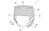
- FIG. 1 is a perspective view of a pants-type disposable diaper according to Embodiment 1.
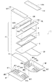
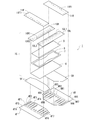
- FIG. 2 is an exploded perspective view of the diaper according to the first embodiment.
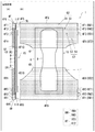
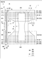
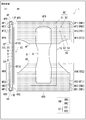
- FIG. 3 is a diagram schematically illustrating a state in which the diaper according to Embodiment 1 is developed.
- FIG. 4 is a diagram for explaining an installation mode of the ventilation path forming sheet of the diaper according to the first embodiment.
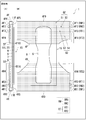
- Drawing 5 is a figure showing typically the state where the diaper concerning a comparative example was developed.
- FIG. 6 is a diagram for explaining the interval between the first rubber threads of the diaper according to the comparative example and the wrinkles formed in the first contraction portion.
- FIG. 7A is a diagram illustrating wrinkles in the first contraction portion of the waist gather according to the first embodiment.
- FIG. 7B is a diagram illustrating wrinkles in the first contraction portion of the waist gather according to the comparative example.
- FIG. 8 is a diagram for explaining the wind speed measurement position in the air permeability quantitative test.
- FIG. 9 is a diagram showing a mist ventilation tester used for the mist ventilation test.
- FIG. 10A is an enlarged photograph of a ridge forming a waist gather according to an example.
- FIG. 10B is an enlarged photograph of a ridge forming a waist gather according to a comparative example.
- FIG. 11 is a diagram schematically illustrating a state in which the diaper according to Embodiment 2 is developed.
- FIG. 12 is a diagram schematically illustrating a state in which the diaper according to Embodiment 3 is developed.
- FIG. 13 is a perspective view of a pants-type disposable diaper according to the fourth embodiment.
- FIG. 14 is an exploded perspective view of a diaper according to the fourth embodiment.
- FIG. 15 is a diagram schematically illustrating a state in which the diaper according to Embodiment 4 is developed.
- FIG. 16 is a diagram for explaining an installation mode of the ventilation path forming sheet of the diaper according to the fourth embodiment.
- FIG. 17 is a diagram illustrating a portion of a joint portion where the air passage formation sheet is joined.
- FIG. 18 is a diagram showing the magnitude of the contraction force in each contraction part.
- FIG. 19 is a diagram for explaining wrinkles formed on the second contraction part of the waist gather and the third contraction part of the Tammy gather.
- FIG. 15 is a diagram schematically illustrating a state in which the diaper according to Embodiment 4 is developed.
- FIG. 16 is a diagram for explaining an installation mode of the ventilation path forming sheet of the diaper according to the fourth embodiment.
- FIG. 17 is a
- FIG. 20 is a diagram schematically illustrating a state in which the diaper according to the modification is developed.
- FIG. 21 is a diagram for explaining wrinkles formed on the first contraction part and the second contraction part of the waist gathers and the third contraction part of the Tammy gathers.
- FIG. 22 is a view showing air holes formed in the opening edge of the trunk opening when the waist gathers contract.
- Embodiment shown below is an example of embodiment of this invention, and does not limit the technical scope of this invention to the following aspects.
- FIG. 1 is a perspective view of a pants-type disposable diaper (hereinafter simply referred to as “diaper”) 1 according to the first embodiment.
- FIG. 2 is an exploded perspective view of the diaper 1 according to the embodiment.
- FIG. 3 is the figure which showed typically the state which expand
- FIG. 3A schematically shows the internal structure of the diaper 1 when unfolded when viewed from the left side.
- the direction used in this specification shall mean the direction which corresponds to the wearer's front and rear, right and left in the state where diaper 1 was worn by the wearer.
- the left-right direction means a direction that matches the left and right of the wearer when the diaper 1 is worn by the wearer.
- the “front body region” of the diaper 1 means a portion that covers the abdomen (front of the body) of the wearer when the diaper 1 is worn on the wearer.
- the “inseam area” of the diaper 1 means a portion that covers the inseam of the wearer when the diaper 1 is worn on the wearer.
- the “rear body region” of the diaper 1 means a portion that covers the wearer's back (back of the body) when the diaper 1 is worn on the wearer.
- the “longitudinal direction” means a direction connecting the front body region and the back body region of the diaper 1. That is, the longitudinal direction of the diaper 1 coincides with the continuous direction in which the front body region, the crotch region, and the back body region are continuously provided.
- the “width direction” means a direction orthogonal to the longitudinal direction of the diaper 1.
- a pants-type disposable diaper having a tubular structure having an opening into which the wearer's abdomen enters and a pair of left and right openings through which the wearer's left lower limb and right lower limb are inserted
- the “absorbent article” in this specification is not limited to a pants-type disposable diaper.
- the “absorbent article” includes, for example, a tape that is fixed near one end of a sheet-like member that covers the wearer's crotch (pubic region) from the front body region to the back body region, and the other end of the sheet-like member.
- Various types of absorbent articles that can wrap the abdominal circumference and crotch such as a tape-type disposable diaper that forms a cylindrical structure by being attached in the vicinity of the part, are included.
- the diaper 1 includes a crotch region 1B that covers the crotch (pubic region) of the wearer, a front body region 1F that covers the abdomen of the wearer, and a back body that covers the back of the wearer. And a region 1R.
- the crotch region 1B is located between the front body region 1F and the back body region 1R and is connected to the front body region 1F and the back body region 1R, and the crotch region 1B absorbs and holds liquid.
- a main body 15 (absorber 8) is provided.
- the diaper 1 in this embodiment is a pants-type disposable diaper
- the left side edge of the front body region 1F and the left side edge of the back body region 1R are joined together, and the right side edge of the front body region 1F and the back body region 1R The right edge is joined to each other, so that the state shown in FIG. 1 is assembled.
- a trunk opening (waist opening) 2T is formed by the upper edge of the front body region 1F and the upper edge of the rear body region 1R.
- a left lower limb opening 2L is formed on the left side of the crotch region 1B where the joining is not performed
- a right lower limb opening 2R is formed on the right side of the crotch region 1B.
- the left lower limb opening 2L and the right lower limb opening 2R are openings through which the wearer's legs are inserted when the diaper 1 is worn.
- the wearer's left lower limb is inserted into the left lower limb opening 2L
- the wearer's right lower limb is inserted into the right lower limb opening 2R
- the wearer's torso enters (passes through) the torso opening 2T.
- the front body region 1F contacts the wearer's abdomen
- the back body region 1R contacts the wearer's back side
- the crotch region 1B is applied to the wearer's crotch
- the left lower limb opening 2L and right lower limb opening 2R are fixed to the wearer's body in a state of surrounding the wearer's thigh. Since the diaper 1 is fixed to the wearer's body in this manner, it is possible to walk while the diaper 1 is worn.
- an absorbent body 8 that can absorb and hold liquid is mainly disposed around the crotch region 1B. Further, in the diaper 1, in order to suppress the formation of a gap as a liquid outflow path between the diaper 1 and the wearer's skin, the left lower limb opening 2 ⁇ / b> L, the right lower limb opening 2 ⁇ / b> R, the torso opening
- the part 2T is provided with a three-dimensional gather G1L, a three-dimensional gather G1R, and a waist gather G2, respectively.
- the three-dimensional gathers G1L and G1R and the waist gather G2 are configured so as to be in close contact with the wearer's skin by the elastic force of the rubber thread, so that the excretory fluid discharged from the wearer is not leaked from the diaper 1. It can be made to absorb in the absorption part main body 15 (absorber 8).
- the diaper 1 has cover sheets 4F and 4R and a pad cover sheet 6 that form an outer surface in a state worn on the wearer.
- the cover sheet 4F is a sheet member that mainly forms the outer surface of the front body region 1F of the diaper 1.
- the pad cover sheet 6 is a sheet member for mainly forming the outer surface of the crotch region 1B of the diaper 1.
- the cover sheet 4R is a sheet member for mainly forming the outer surface of the rear body region 1R of the diaper 1.
- the cover sheets 4F and 4R and the pad cover sheet 6 are provided, for example, for reinforcing the outer surface of the diaper 1 and improving the touch.
- the cover sheets 4F and 4R and the pad cover sheet 6 can be formed of a nonwoven fabric made of, for example, a liquid-impermeable thermoplastic resin in order to suppress leakage of excrement.
- the liquid-impermeable thermoplastic resin include polyethylene (PE) and polypropylene (PP).
- PE polyethylene
- PP polypropylene
- the liquid-impermeable sheet may have a large number of fine pores of about 0.1 to several ⁇ m so that the liquid-impermeable and moisture-permeable properties are exhibited.
- the diaper 1 has the inner cover sheet 5F laminated
- the “skin facing surface” means a surface facing the wearer's skin when the wearer wears the diaper 1.
- the inner cover sheet 5F is a sheet member that is bonded to the cover sheet 4F in a state where a rubber thread that is a linear elastic member is sandwiched between the cover sheet 4F and the interlayer.
- the inner cover sheet 5F is a sheet member having a shape and a size corresponding to a portion of the cover sheet 4F excluding the folded portion 4F5 described later and the waist first region RW1 in the exterior cover portion 4F10.
- the inner cover sheet 5R is a sheet member that is bonded to the cover sheet 4F in a state in which a thread rubber that is a linear elastic member is sandwiched between the layers with the cover sheet 4R.
- the inner cover sheet 5R is a sheet member having a shape and a size corresponding to a portion of the cover sheet 4R excluding the folded portion 4R5 described later and the waist first region RW1 in the exterior cover portion 4R10.
- the diaper 1 of the present embodiment includes an absorbent body 15.
- the absorbent main body 15 is held in a state of being bridged between the front body region 1F and the back body region 1R, and is placed on the inseam of the wearer when the diaper 1 is worn, and liquid such as urine excreted by the wearer. Absorb and hold.
- the absorbent body 15 includes a pad cover sheet 6, a back sheet 7, an absorbent body 8, a center sheet 9, side sheets 10 ⁇ / b> L, 10 ⁇ / b> R, and the like, and is integrally formed by these. .
- the back sheet 7, the absorber 8, and the center sheet 9 are laminated in order on the skin facing surface of the pad cover sheet 6.
- the pad cover sheet 6 has a length in the longitudinal direction that reaches from the wearer's front body to the back body through the crotch, and has a rectangular plane having a predetermined lateral width in the width direction orthogonal to the longitudinal direction. It is a sheet member to have.
- the back sheet 7, the absorbent body 8, and the center sheet 9 are all sheet members having a rectangular plane like the pad cover sheet 6, and the pad cover is in a state where the longitudinal direction coincides with the longitudinal direction of the pad cover sheet 6.
- the sheets 6 are laminated in this order.
- the absorber 8 is a member that absorbs liquid such as urine and holds the absorbed liquid.
- the absorber 8 is disposed between the liquid-impermeable back sheet 7 and the liquid-permeable center sheet 9.
- Absorbent body 8 has water in gaps between short fibers of cellulose fibers such as pulp fibers, rayon fibers, or cotton fibers, or short fibers obtained by subjecting synthetic fibers such as polyethylene, polypropylene, or polyethylene terephthalate to hydrophilic treatment. It may have a structure in which a granular absorbent resin such as a hydrophilic superabsorbent polymer having a cross-linked structure capable of absorbing and retaining water is retained.
- the absorber 8 may have a single layer structure made of one mat or a laminated structure in which a plurality of mats are stacked. Moreover, the absorber 8 can employ
- the center sheet 9 is a sheet member that directly contacts the skin of the wearer's crotch and allows liquid such as urine to pass through the absorbent body 8, and is laminated so as to cover the water absorption surface of the absorbent body 8.
- the center sheet 9 in the present embodiment is formed of a highly permeable liquid permeable material. Examples of the liquid permeable material forming the center sheet 9 include a woven fabric, a nonwoven fabric, and a porous film.
- the center sheet 9 may have hydrophilicity.
- the back sheet 7 is a sheet member for suppressing the liquid that has passed through the center sheet 9 and absorbed by the absorber 8 from leaking to the outside of the diaper 1. For this reason, the back sheet 7 is formed of a liquid-impermeable material.
- the liquid impermeable material forming the back sheet 7 include a liquid impermeable film made of polyethylene resin.
- the backsheet 7 may be formed of a microporous polyethylene film in which a large number of micropores are formed in order to ensure air permeability.
- the pad cover sheet 6 is a member for reinforcing the back sheet 7 and improving the touch thereof, and is bonded to the back sheet 7.
- Examples of the material forming the pad cover sheet 6 include woven fabric and non-woven fabric.
- the pad cover sheet 6 may be a nonwoven fabric or a wet nonwoven fabric made of a thermoplastic resin such as polyethylene, polypropylene, or polyester.
- the side sheets 10L and 10R in the absorber main body 15 are elongated strip-shaped members for forming the above-described three-dimensional gathers G1L and G1R.
- the side sheets 10 ⁇ / b> L and 10 ⁇ / b> R are extended along the long side portion of the center sheet 9. Further, thread rubbers 10L1 and 10R1 are bonded to the side sheets 10L and 10R along the longitudinal direction.
- the left side edge 4F7 of the cover sheet 4F forming the left side edge of the front body region 1F and the left side edge 4R7 of the cover sheet 4R forming the left side edge of the back body region 1R are joined together, and the right side edge of the front body region 1F is joined When the diaper 1 shown in FIG.
- a method for joining the side edges of the cover sheets 4F and 4R is not particularly limited, and examples thereof include heat sealing, high frequency sealing, and ultrasonic sealing.
- the absorbent body 15 extends from the front body region 1F to the back body region 1R.
- the cover sheet 4F has a folded portion 4F5 formed by folding the front end side inward with a fold line 4F6 as a boundary.
- a portion of the cover sheet 4F excluding the folded portion 4F5 is referred to as an exterior cover portion 4F10.
- the exterior cover portion 4F10 of the cover sheet 4F forms the outer surface of the diaper 1.
- the fold line 4F6 of the cover sheet 4F forms a trunk opening edge 4F9 of the trunk opening 2T in a state where the diaper 1 is assembled.
- the folded-back portion 4F5 in the cover sheet 4F has an extended first thread rubber 4F1 disposed between the outer cover portion 4F10 and the interlayer. Further, the front end side of the folded portion 4F5 in the cover sheet 4F is a state in which one end side in the longitudinal direction of the inner cover sheet 5F, the pad cover sheet 6, the back sheet 7 and the absorbent body 8 is sandwiched between the layers with the exterior cover portion 4F10. Thus, the absorbent body 8 is bonded in a state of being overlapped with one end portion.
- the aspect at the time of expressing that one member and another member are overlapped is not limited to an aspect in which the members overlap each other in a state of being in full contact with each other. It is a concept including a mode in which a part of the other member and the whole of the other member overlap, or a mode in which a part of one member and the other member overlap each other.
- the second thread rubber 4F2, the third thread rubber 4F3, and the fourth thread rubber 4F4 are arranged from the folding line 4F6 side. However, they are arranged in this order, and are bonded in a state of being sandwiched between the outer cover portion 4F10 and the inner cover sheet 5F.
- a plurality of first thread rubbers 4F1 to 4F thread rubbers 4F4 in the cover sheet 4F are arranged in parallel, and all of them are along the width direction (the waistline direction) of the cover sheet 4F. It is extended.
- the cover sheet 4R also has a folded portion 4R5 formed by folding the front end side inward with the fold line 4R6 as a boundary.
- a portion of the cover sheet 4R excluding the folded portion 4R5 is referred to as an exterior cover portion 4R10.
- the exterior cover portion 4R10 of the cover sheet 4R forms the outer surface of the diaper 1.
- the folding line 4R6 of the cover sheet 4R forms a trunk opening edge 4R9 of the trunk opening 2T in a state where the diaper 1 is assembled.
- the extended first thread rubber 4R1 is disposed between the outer cover portion 4R10 and the interlayer.
- the other end side of the inner cover sheet 5R, the pad cover sheet 6, the back sheet 7, and the absorbent body 8 in the longitudinal direction is sandwiched between the outer cover part 4R10 and the front end side of the folded portion 4R5 in the cover sheet 4R. In the state, it is bonded in a state of being overlapped with the other end portion of the absorber 8.
- the second thread rubber 4R2, the third thread rubber 4F3, and the fourth thread rubber 4R4 from the folding line 4R6 side are arranged in this order, and are bonded in a state of being sandwiched between the outer cover portion 4R10 and the inner cover sheet 5R.
- a plurality of first rubber threads 4R1 to 4R4 in the cover sheet 4R are arranged in parallel, each along the width direction (the waistline direction) of the cover sheet 4R. It is extended.
- the waist area RW of the diaper 1 is an area where the waist gathers G2 are formed in the vicinity of the trunk opening edges 4F9 and 4R9 forming the trunk opening 2T.
- a region where the first rubber threads 4F1 and 4R1 are disposed is referred to as a “waist first region RW1” (first region), and a region where the second rubber rubbers 4F2 and 4R2 are disposed. Is referred to as “waist second region RW2” (second region).
- an area where the third thread rubbers 4F3 and 4R3 and the fourth thread rubbers 4F4 and 4R4 are arranged is referred to as a “tammy area RT”.
- the Tammy region RT is a region located below the waist region RW.
- the region where the third rubber threads 4F3, 4R3 are disposed is referred to as “tammy first region RT1”, and the region where the fourth rubber rubbers 4F4, 4R4 are disposed is referred to as “tammy second region RT2.
- the first rubber threads 4F1 and 4R1 in the waist first region RW1 are applied with an adhesive in an expanded state in the assembly process of the diaper 1, for example, and then the exterior cover portions 4F10 and 4R10 and the folded portions 4F5 are applied. By being sandwiched between 4R5, it adheres between these layers.
- the second thread rubbers 4F2 and 4R2 in the waist second region RW2 and the third thread rubbers 4F3 and 4R3 and the fourth thread rubbers 4F4 and 4R4 in the tammy region RT are expanded in the assembly process of the diaper 1, for example. After the adhesive is applied in this state, it is bonded between the outer cover portions 4F10, 4R10 of the cover sheets 4F, 4R and the inner cover sheets 5F, 5R by being sandwiched between them.
- the first rubber threads 4F1 and 4R1 in the waist first region RW1 that are sandwiched and bonded between the outer cover portions 4F10 and 4R10 and the inner cover sheets 5F and 5R in the cover sheets 4F and 4R are contracted.
- the portion corresponding to the waist first region RW1 of the exterior cover portions 4F10, 4R10 and the folded portions 4F5, 4R5 is continuously bent in a pleated shape to follow the waist first region RW1 in the waistline direction.
- a first contraction portion S1 that contracts is formed.
- the exterior follows the shrinkage.
- the second contraction that contracts the waist second region RW2 in the waistline direction by continuously bending the portion corresponding to the waist second region RW2 in a pleated shape. Part S2 is formed.
- the waist gather G2 is formed mainly by the first contraction portion S1 formed in the waist first region RW1 and the second contraction portion S2 formed in the waist second region RW2.
- the waist gather G2 improves the fit of the diaper 1 around the wearer's waist by the contraction force of the first thread rubber 4F1, 4R1 and the second thread rubber 4F2, 4R2.
- first contraction portion S1 of the waist gather G2 three first rubber threads 4F1 and 4R1 are arranged in parallel with each other at a constant interval A1.
- a plurality of second rubber threads 4F2 and 4R2 are provided in the second contraction portion S2 of the waist gather G2 in parallel with each other and at a constant interval A2.
- the interval A1 between the first thread rubbers 4F1 and 4R1 in the first contraction portion S1 is set to be larger than the interval A2 between the second thread rubbers 4F2 and 4R2 in the second contraction portion S2. Therefore, the first contraction portion S1 ensures the moisture discharging function of discharging the moisture in the internal space of the diaper 1 to the outside and the function of easily expanding the trunk opening 2T.
- the 2nd contraction part S2 of waist gathers G2 raises the contraction force in the circumference direction of the waist compared with the 1st contraction part S1, and the position maintenance function (displacement suppression) which controls slippage at the time of wearing of the diaper 1 Function).
- interval of thread rubber here means the dimension which spaces apart adjacent thread rubber in the longitudinal direction (direction which connects a front body area
- the first rubber bands 4F1 and 4R1 in the first waist region RW1 and the second rubber bands 4F2 and 4R2 in the second waist region RW2 extend over the entire width section of the cover sheets 4F and 4R. ing. Therefore, after the diaper 1 is completed, the first rubber threads 4F1 and 4R1 and the second rubber threads 4F2 and 4R2 form a substantially annular elastic member that circulates along the trunk opening 2T. In other words, after the diaper 1 is completed, the waist gather G2 (the first contraction part S1 and the second contraction part S2) is formed over the entire circumference in the waistline direction.
- the third rubber threads 4F3 and 4R3 which are sandwiched and bonded in an extended state between the outer cover portions 4F10 and 4R10 and the inner cover sheets 5F and 5R in the cover sheets 4F and 4R are contracted.
- the portion corresponding to the first tammy region RT1 is continuously bent in a pleated shape, so that A third contraction portion S3 that contracts one region RT1 in the waistline direction is formed.
- contraction part S3 is an area
- the fourth thread rubbers 4F4 and 4R4 which are sandwiched and bonded in an extended state between the outer cover portions 4F10 and 4R10 and the inner cover sheets 5F and 5R in the cover sheets 4F and 4R are also provided.
- the portion corresponding to the Tammy second region RT2 of the exterior cover portions 4F10, 4R10 and the inner cover sheets 5F, 5R in the cover sheets 4F, 4R continuously bends in a pleated shape.
- a fourth contraction portion S4 that contracts the Tammy second region RT2 in the waistline direction is formed.
- a Tammy gather G3 is formed mainly by the third contraction part S3 formed in the Tammy first region RT1 and the fourth contraction part S4 formed in the Tammy second region RT2.
- the Tammy Gather G3 improves the fit of the diaper 1 around the lower abdomen of the wearer, for example, by the contraction force of the third rubber threads 4F3 and 4R3 and the fourth rubber threads 4F4 and 4R4.
- the thread rubbers 4F1, 4R1, 4F2, 4R2, 4F3, 4R3, 4F4, 4R4 are attached to the cover sheets 4F, 4R.
- “linear” represents an elongated shape extending in a specific direction, and is a concept including a strip shape and a strip shape.
- natural rubber, synthetic rubber, etc. can be illustrated as a material of thread rubber, However, It is not limited to a specific material.
- the air passage forming sheets 11F and 11R of the diaper 1 will be described.
- the diaper 1 straddles the folded end portions 4F5 and 4R5 in the cover sheets 4F and 4R, and the end regions in the longitudinal direction of the pad cover sheet 6 and the center sheet 9 in the absorbent body 15.
- the folded-back portions 4F5 and 4R5 and the pad cover sheet 6 are provided with the air passage forming sheets 11F and 11R stacked on the skin.
- the ventilation path forming sheets 11F and 11R form a skin contact surface in the waist gather G2 of the diaper 1.
- the “skin contact surface” means a surface that directly contacts the wearer's skin when the diaper 1 is worn, that is, the innermost surface of the diaper 1.
- FIG. 4 is a diagram illustrating an installation mode of the air passage forming sheets 11F and 11R of the diaper 1 according to the embodiment.
- (A) of FIG. 4 is a figure which shows the state which looked at 1st contraction part S1 of waist gathers G2 from the internal space side of the diaper 1.
- FIG. Moreover, (B) of FIG. 4 is a figure which shows typically the internal structure in 1st contraction part S1 of the waist gather G2 at the time of seeing from the side of the diaper 1.
- (C) of FIG. 4 is a figure which shows the state which looked at 1st contraction part S1 of waist gathers G2 from the upper direction (namely, A arrow direction of (B)) of the diaper 1.
- FIG. 4A and 4C show a state before the first contraction portion S1 of the waist gather G2 contracts for convenience.
- (D) of FIG. 4 is a figure which shows the state which looked at 1st shrinkage
- the ventilation path forming sheets 11F and 11R are laminated and arranged so as to cover at least a part of the folded portions 4F5 and 4R5 forming the skin facing surface in the first contraction portion S1 of the waist first region RW1. Are joined to the end region in the longitudinal direction of the pad cover sheet 6 and the folded portions 4F5 and 4R5.
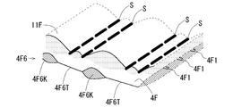
- the folded portions 4F5 and 4R5 of the cover sheets 4F and 4R formed of the thermoplastic resin and the air passage forming sheets 11F and 11R superimposed on the pad cover sheet 6 are joined by ultrasonic welding, thereby joining. Part S is formed. As shown in FIG.
- a plurality of joints S are intermittently arranged along the longitudinal direction perpendicular to the trunk direction (width direction) from the trunk opening edges 4F9, 4R9 of the cover sheets 4F, 4R.
- the linear junction part SL extended in the longitudinal direction of the diaper 1 is formed.
- one linear joint portion SL is formed as an assembly of a plurality of joint portions S that are intermittently arranged along the longitudinal direction of the diaper 1.
- “intermittently” means an aspect of being discontinuously or intermittently arranged.
- a plurality of linear joints SL are intermittently provided along the waistline direction (width direction) of the cover sheets 4F and 4R in the first contraction part S1 of the waist gather G2.
- the linear joint portions SL are provided in parallel to each other, and the intervals between the linear joint portions SL are set to be alternately large and small.
- the linear joints SL are intermittently arranged in such a manner that double lines formed by a set of linear joints SL are arranged at equal intervals in the waistline direction (width direction).
- FIG. 3 (A) the range which the linear junction part SL extends in the longitudinal direction of the diaper 1 is shown by hatching. As illustrated, the linear joint portion SL extends across the waist first region RW1 where the first contraction portion S1 is formed and the waist second region RW2 where the second contraction portion S2 is formed.
- the ultrasonic bonding of the air passage forming sheets 11F and 11R to the folded portions 4F5 and 4R5 and the like is performed in a state where the first thread rubbers 4F1 and 4R1 and the second thread rubbers 4F2 and 4R2 of the waist gather G2 are in the extended state.
- the first thread rubbers 4F1, 4R1 and the second thread rubbers 4F2, 4R2 that are sandwiched and fixed between the sheet layers are stretched. Canceled.
- the waist gather G2 contracts, so that the interval between the linear joint portions SL in the air passage forming sheets 11F and 11R is narrowed.
- the folded portions 4F5, 4R5 of the cover sheets 4F, 4R and the non-bonded regions 110 in the air passage forming sheets 11F, 11R are separated from each other, and as shown in FIG. A first air passage 111 surrounded by the non-joining regions 110 of the air passage forming sheets 11F and 11R is formed.
- the 2nd ventilation path 112 can be formed in the skin contact surface 11a side of the ventilation path formation sheets 11F and 11R.
- Reference sign SS indicated by a two-dot chain line in FIG. 4 (D) indicates the skin surface in contact with the air passage forming sheets 11F and 11R as a virtual line when the diaper 1 is worn by the wearer.
- the second air passage 112 is formed as a gap formed between the skin contact surface 11a of the air passage forming sheets 11F and 11R and the skin of the wearer when the diaper 1 is worn by the wearer. Moisture in the internal space of the diaper 1 can be discharged to the outside through the first air passage 111 and the second air passage 112 formed in the waist gather G2.
- the 1st ventilation path 111 is a ventilation path through which the moisture which permeate
- the second ventilation path 112 is a ventilation path that directly communicates the internal space and the external space of the diaper 1, and can discharge the moisture in the diaper 1 more smoothly.
- first contraction portion S1 As shown in FIG. 4D, after the shrinkage of the waist gather G2, there are a relatively large first ridge 41 and a relatively small second ridge 42 forming the first contraction portion S1. It is formed alternately.
- the relatively large first ridges 113 and the relatively small second ridges 114 are alternately formed in the air passage forming sheets 11F and 11R that are bent and deformed in the waveform. This is due to the fact that the intervals between the linear joint portions SL are set to be alternately large and small. That is, a large first rod 41, 113 is formed by a set of linear joints SL having a large interval, and a small second rod 42, 114 is formed by a set of linear junctions SL having a small interval.
- the first ridge 113 of the airflow passage forming sheets 11F and 11R that are bent and deformed in a waveform is to cooperate with the first ridge 41 that forms the first contraction portion S1 in order to secure a large first airflow passage 111.
- the second ridge 114 of the ventilation path forming sheets 11F and 11R cooperates with the second ridge 42 forming the first contraction portion S1 to form the first ventilation path 111 and in the waistline direction (width direction). This contributes to properly separating the adjacent first flanges 113 and securing a ventilation cross section of the second ventilation path 112.
- the flute structure formed by the airflow passage forming sheets 11F and 11R that deforms into a corrugated shape following the contraction of the first contraction part S1 is provided on the skin contact surface side of the waist gather G2.
- the moisture in the diaper 1 can be efficiently discharged to the outside through the first air passage 111 and the second air passage 112.
- the linear junction part SL is formed as an aggregate
- the adjacent first ventilation paths 111 are communicated with each other. Therefore, it is possible to improve the air permeability between the adjacent first air passages 111 and make it difficult for the wearer to receive a local feeling of stuffiness.
- the ventilation path forming sheets 11F and 11R in the present embodiment are provided with a large number of fine ventilation holes 11F1 and 11R1 for ventilation.
- the air hole means an opening that allows communication between the space on one side of the sheet and the space on the other side, and the shape thereof is not particularly limited. Therefore, as the vent holes 11F1 and 11R1, for example, openings having a shape such as a circle, an ellipse, and a polygon (triangle, square, etc.) can be applied.
- the formation of the air holes 11F1, 11R1 in the air passage forming sheets 11F, 11R does not mean that the air passage forming sheets 11F, 11R are a material having no air permeability, and the air passage forming sheets 11F, 11R, 11R may be either a breathable material or a non-breathable material.
- the air passage forming sheets 11F and 11R are preferably made of a material having air permeability and liquid permeability, but may be a non-breathable material, for example.
- the size and the number of the vent holes 11F1 and 11R1 are not particularly limited. For example, if the opening area is 0.5 to 10 mm 2 , about 5 to 200 are preferably formed.
- the diaper 1 which concerns on this embodiment makes the 1st contraction part S1 located in the trunk
- the installation mode of the second rubber threads 4F2 and 4R2 (second elastic members) to be arranged is made different.
- the first contraction portion S1 by setting the interval A1 between the first rubber threads 4F1 and 4R1 in the first contraction portion S1 to be larger than the interval A2 between the second yarn rubbers 4F2 and 4R2 in the second contraction portion S2, the first contraction portion.
- the moisture discharge function in S1 and the slip-off suppressing function in the second contraction portion S2 are compatible.
- the present inventors have arranged the first rubber threads 4F1 and 4R1 forming the first contraction part S1 at a constant interval, and the interval A1 is 6.5 mm or more and 20 mm or less.
- the breathability and ease of attachment / detachment of the waist gather G2 in the diaper 1 can be improved as compared with the prior art, and in particular, setting the interval A1 to 6.5 mm or more and 13 mm or less From the viewpoint of improving air permeability and ease of attachment / detachment, it has been found that it is more preferable.
- the effect of the diaper 1 which concerns on Embodiment 1 is demonstrated by contrasting the diaper 1 which concerns on Embodiment 1 and the diaper 101 which concerns on a comparative example.
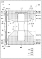
- FIG. 5 is a diagram schematically showing a state in which the diaper 101 according to the comparative example is unfolded.
- A) of FIG. 5 has shown typically the internal structure at the time of seeing the diaper 101 at the time of expansion
- B) of FIG. 5 has shown typically the planar structure of the diaper 101 at the time of expansion
- the diaper 101 which concerns on a comparative example is the same as the diaper 1 which concerns on Embodiment 1 shown by FIG. 3 etc. except the point from which the number and space
- the first rubber threads 4F1 and 4R1 extend in the left-right direction along the trunk opening edges 4F9 and 4R9 of the cover sheets 4F and 4R, respectively.
- Five first rubber bands 4F1 and 4R1 of the diaper 101 according to the comparative example are arranged in parallel with a predetermined distance B1 therebetween.
- the distance B1 between the first thread rubbers 4F1 and 4R1 of the diaper 101 according to the comparative example is smaller than the distance A1 between the first thread rubbers 4F1 and 4R1 in the diaper 1 according to the first embodiment.
- the interval B1 between the first rubber threads 4F1 and 4R1 of the diaper 101 according to the comparative example is set to 5 mm.
- FIG. 6 is a diagram for explaining the gap B1 between the first rubber threads 4F1 and 4R1 of the diaper 101 according to the comparative example and the wrinkles formed in the first contraction portion S1.
- 6A to 6D correspond to FIGS. 4A to 4D, respectively.
- (A) of Drawing 6 is a figure showing the state which looked at waist gather G2 (1st contraction part S1) in waist 1st field RW1 from the internal space side of diaper 101 about diaper 101 of a comparative example.
- (B) of FIG. 6 is a figure which shows typically the internal structure in waist gather G2 (1st contraction part S1) in waist 1st area
- FIG. 6 is a figure which shows the state which looked at waist 1st area
- FIG. 6A and 6C show a state before the waist gather G2 (first contraction portion S1) in the waist first region RW1 is contracted for convenience.
- (D) in FIG. 6 is a figure which shows the state which looked at the diaper 101 from upper direction in the state which waist gather G2 (1st contraction part S1) contracted.
- 41 and the size of the second ridge 42 are larger in the diaper 1 according to the first embodiment than in the diaper 101 according to the comparative example. The reason is as follows.
- FIG. 7A is a diagram illustrating wrinkles in the first contraction portion S1 of the waist gather G2 in the first embodiment.
- (A) of FIG. 7A is a figure which shows typically the state which looked at the wrinkles in 1st contraction part S1 of Embodiment 1 from the front.
- FIG. 7B is a diagram schematically illustrating a state in which the eyelids in the first contraction portion S1 of the first embodiment are viewed from the side surface.
- FIG. 7B is a diagram illustrating wrinkles in the first contraction portion S1 of the waist gather G2 according to the comparative example.
- FIG. 7B is a diagram schematically illustrating a state in which the eyelids in the first contraction portion S1 of the comparative example are viewed from the front.
- (B) of Drawing 7B is a figure showing typically the state where the eyelid in 1st contraction part S1 of a comparative example was seen from the side.
- first thread rubbers 4F1 and 4R1 provided in the first contraction part S1 are bonded to the exterior cover parts 4F10 and 4R10 and the folded parts 4F5 and 4R5 of the cover sheets 4F and 4R, the first thread rubber 4F1.
- 4R1 cover sheets 4F, 4R first and second ribs 41, 42, and air passage forming sheets 11F, 11R first flange 113 and second flange 114 are first thread rubber 4F1, The closer the distance from 4R1, the higher the degree of restraint by the first rubber threads 4F1 and 4R1.
- the distance A1 between the first thread rubbers 4F1 and 4R1 of the diaper 1 according to the first embodiment is wider than the distance B1 between the first thread rubbers 4F1 and 4R1 of the diaper 101 according to the comparative example. Therefore, in the diaper 1 of the first embodiment, the first ridge 41 and the second ridge 42 of the cover sheets 4F and 4R and the first ridge 113 and the second ridge 114 of the air passage forming sheets 11F and 11R are the diapers 101 of the comparative example. Compared to the above, it is difficult to receive the restraining force of the first rubber threads 4F1 and 4R1 as a whole.
- the diaper 1 of Embodiment 1 includes the first ridge 41 and the second ridge 42 of the cover sheets 4F and 4R, the first ridge 113 and the first ridge 113 of the ventilation path forming sheets 11F and 11R. It becomes possible to enlarge 2 ⁇ 114.
- size of the 1st collar 41 and the 2nd collar 42 formed in the 1st contraction part S1 of waist gathers G2 Since the height can be increased, the ventilation area of the first ventilation path 111 can be further increased.
- size of the 1st ridge 113 and the 2nd ridge 114 formed in the ventilation path formation sheet 11F, 11R is enlarged. Can do. Thereby, the ventilation area of the 1st ventilation path 111 and the 2nd ventilation path 112 can be enlarged further. From the above, according to the diaper 1 according to the embodiment, moisture in the diaper 1 can be discharged more smoothly.
- the diaper 1 is compressed from the outside when the wearer takes a sitting position, and the diaper 1 is deformed by the movement of the leg when the wearer walks.
- moisture in the diaper 1 can be discharged to the external space through the first air passage 111 and the second air passage 112, and the internal space of the diaper 1 can be made a comfortable environment.
- emission of moisture from the inside of a diaper with the compression deformation of the diaper 1 compared with the comparative example, the 1st collar 41 and the 2nd collar 42 of cover sheet 4F, 4R, and ventilation path formation By combining with the installation mode of the first rubber threads 4F1 and 4R1 in the first contraction part S1, which contributes to increasing the first ridges 113 and the second ridges 114 of the sheets 11F and 11R, the breathability of the waist gather G2 is increased. It is possible to obtain a synergistic effect that can be improved more remarkably.
- the 1st contraction part S1 which forms waist gather G2 is extended from the trunk
- the torso opening 2T when the torso opening 2T is widened, if the fingertip side of the first joint of the finger is positioned on the torso opening edges 4F9 and 4R9, the torso opening is being performed while the torso opening 2T is being widened. It becomes easy for a fingertip to come off from the end edges 4F9, 4R9 unexpectedly.
- the torso opening 2T when expanding the torso opening 2T, if the base part of the finger deeper than the second joint is located at the torso opening edge 4F9, 4R9, the second position is located below the first contraction part S1. 2 The contraction part S2 is expanded, and it is difficult to efficiently expand the trunk opening 2T.
- the easiness of attachment / detachment of the diaper 1 can be improved by setting the extending length of the first contraction part S1 along the longitudinal direction of the diaper to be not less than 26 mm and not more than 31 mm. Further, when the diaper 1 is spread, the tips of the fingers do not bite into the air passage forming sheets 11F and 11R that form the skin contact surface of the waist gather G2 of the diaper 1, and the air passage forming sheets 11F and 11R are damaged. There is also an advantage that this can be suppressed.
- the first contraction portion S1 has a laminated structure in which the sheet members are laminated in at least three layers. According to this, when putting the diaper 1 on the baby (wearer), even when the operator's finger enters between the first rubber bands 4F1 and 4R1 arranged in the first contraction part S1, It can suppress that a tear generate
- the width dimension which 2nd contraction part S2 extends to a diaper longitudinal direction shall be 10 mm or more.
- variety to the diaper longitudinal direction of 2nd contraction part S2 shall be 26 mm or less.
- a diaper corresponding to an example of the diaper 1 according to the embodiment and a diaper corresponding to the diaper 101 according to the comparative example are prepared, and a breathability quantitative test, a mist ventilation test, and a widening strength test are performed on each diaper. Etc. were carried out.
- a diaper corresponding to an example of the diaper 1 according to the embodiment is referred to as an “example”, and a diaper corresponding to the diaper 101 of the comparative example is referred to as a “comparative example”.
- FIG. 8 is a diagram for explaining the wind speed measurement position in the air permeability quantitative test.
- wind speed As a test condition, when a diaper to be tested is attached to a dummy doll and air is injected at 20 L / min from the inseam of the dummy doll, the speed of the air discharged from the inside of the diaper (wind speed) is It measured with the wind speed measuring device.
- a commercially available hot-wire anemometer manufactured by Testo Co., Ltd., product number: testo425, wind speed resolution: 0.01 m / s
- Table 1 shows various specifications of the examples and comparative examples.
- the number of samples to be used for the test three types of Big size, L size, and M size were prepared for each of Examples 1 to 3 and Comparative Examples 1 to 3, respectively.
- interval of 1st thread rubber 4F1 and 4R1 which form 1st contraction part S1 in waist gather G2 show a draft rate in a table
- the waist gather G2 was provided with an air passage forming sheet.
- the comparative example 3 set it as the specification which does not provide a ventilation path formation sheet in waist gather G2.
- the wind speed was measured at five locations A to E having different vertical separation distances from the edge of the trunk opening at the center in the width direction of the back body part of the diaper. It was measured.
- the up-down direction here is a direction orthogonal to the width direction along the exterior surface of a diaper.
- the measurement position A was 1 cm above the edge of the trunk opening.
- the measurement positions B to E are located below the trunk opening edge, and the separation distances from the trunk opening edge are 0.5 cm, 1.5 cm, 2.5 cm, and 3. It was 5 cm.
- the wind speed measurement probe is held in a vertical position with respect to the outer surface (cover sheet surface) of the diaper, and the wind speed is measured with the tip of the probe facing the outer surface of the diaper. Carried out.
- the probe of the wind speed measuring device was held in a posture along the back of the dummy doll, and the tip of the probe was opposed to the gap between the back of the dummy doll and the waist gathers of the diaper. The wind speed was measured in the state.
- Table 2 shows the results of the breathability quantitative test.
- Measured position A is considered to be dominated by the flow of air that leaks outside through the gap between the waist gather G2 and the skin of the dummy doll. Accordingly, considering the measurement results of the wind speed at the measurement position A for each example and each comparative example, as shown in Table 2, Example 1 (yarn rubber interval 6.5 mm), Example 2 (yarn rubber interval 13 mm) ) And Example 3 (thread rubber interval 20 mm), the wind speed is remarkably increased as compared with Comparative Example 1 (thread rubber interval 5 mm) and Comparative Example 3 (thread rubber interval 5 mm, no air passage forming sheet). Results were obtained. Therefore, it can be said that Examples 1 to 3 have significantly improved air permeability of the waist gather G2 compared to Comparative Examples 1 and 3.
- the air permeability of the waist gather G2 can be improved by securing the interval between the first rubber threads 4F1 and 4R1 forming the first contraction part S1 in the waist gather G2 to 6.5 mm or more.
- measurement positions B to E no significant difference was observed between each example and each comparative example.
- Table 2 also shows sensory evaluation results regarding ease of attachment / detachment (easy to attach / detach) of Examples and Comparative Examples.
- the sensory evaluation was evaluated by five evaluators. Out of 5 evaluators, 4 or more responded as good, rated as ⁇ , 3 as good as ⁇ , and 2 or less as good as x did.
- Comparative Example 1 and Comparative Example 3 in which the interval between the thread rubbers in the waist gather G2 is set to 5 mm, the thread rubber in the waist gathers G2 has a high contraction force, and the waist rubber G2 stretches when the diaper is worn. I needed a lot of power.
- Comparative Example 2 in which the gap between the rubber bands in the waist gather G2 was set to 25 mm resulted in the fingers not being caught because the gap between the rubber bands was too wide. From this, it can be said that it is preferable that the distance between the rubber threads of the waist gather G2 is 20 mm or less from the viewpoint of easy attachment / detachment of the diaper. Further, in Comparative Example 2, the breathability of Examples 1 to 3 and waist gather G2 was substantially the same, but Comparative Example 2 was inferior to Examples 1 to 3 in terms of ease of attaching / detaching diapers.
- the interval between the first thread rubbers 4F1 and 4R1 forming the first contracted portion S1 in the waist gather G2 is 6. It can be evaluated that setting to 5 mm or more and 20 mm or less is preferable.
- the breathability of the waist gather G2 is substantially the same, but the diaper easy attachment / detachment is the same as in Example 3 (yarn rubber interval 6. mm) compared to Example 3 (yarn rubber interval 20 mm). 5 mm) and Example 2 (13 mm rubber thread spacing) were even better.
- setting the interval between the first rubber threads 4F1 and 4R1 forming the first contracted portion S1 in the waist gather G2 to 6.5 mm to 13 mm improves the breathability and ease of attachment and removal of the waist gather G2. Therefore, it can be said that it is particularly preferable.
- mist aeration test is performed using a mist aeration test machine 200 shown in FIG. 9, in which a diaper to be tested (Example 1 and Comparative Example 1) is attached to a diaper attachment portion 202 having a mist injection outlet 201.
- a diaper to be tested Example 1 and Comparative Example 1
- mist injection outlet 201 When air containing a constant amount of mist (flow rate 5 m / min) was continuously sent out for 15 seconds, the state of mist passing through the diaper waist gathers was visually observed.
- the mist outlet 201 has a rectangular shape with a vertical dimension of 25 mm and a horizontal dimension of 25 mm, and a diaper to be tested is attached to the diaper attachment portion 202 so that the waist gather G2 is positioned in front of the mist outlet 201.
- the test was conducted.
- FIG. 9 shows a state in which mist is ejected from the mist ejection port 201 in a state where the diaper is not attached to the diaper attachment part 202.
- Example 1 has more mist leaking from the waist gathers in the longitudinal direction than Comparative Example 1.
- Comparative Example 1 since the space
- FIG. 10A is an enlarged photograph of a ridge forming a waist gather according to an example.
- FIG. 10B is an enlarged photograph of a ridge forming a waist gather according to a comparative example. Comparing the example and the comparative example, it can be seen that the size of the wrinkles forming the waist gathers is larger in the example than in the comparative example. In other words, it can be said that the air permeability of the waist gather is better in the example than in the comparative example.
- the first contraction portion S1 is provided in the waist first region RW1 adjacent to the waist opening edges 4F9, 4R9 and is extended along the waistline direction. 4R1 is included, and the trunk opening is contracted in the trunk circumference direction.
- the second contraction portion S2 includes second thread rubbers 4F2 and 4F2 provided in the waist second region RW2 adjacent to the crotch region 1B side with respect to the first contraction portion S1 and extending along the waistline direction, The trunk opening is contracted in the trunk circumference direction.
- the 1st contraction part S1 which forms waist gather G2 is extended from the trunk
- the torso opening 2T when the torso opening 2T is widened, if the fingertip side of the first joint of the finger is positioned on the torso opening edges 4F9 and 4R9, the torso opening is being performed while the torso opening 2T is being widened. It becomes easy for a fingertip to come off from the end edges 4F9, 4R9 unexpectedly.
- the torso opening 2T when expanding the torso opening 2T, if the base part of the finger deeper than the second joint is located at the torso opening edge 4F9, 4R9, the second position is located below the first contraction part S1. 2 The contraction part S2 is expanded, and it is difficult to efficiently expand the trunk opening 2T.
- the easiness of attachment / detachment of the diaper 1 can be improved by setting the extending length of the first contraction part S1 along the longitudinal direction of the diaper 1 to 26 mm or more and 31 mm or less. Further, the first contraction portion S1 requires less force (widening strength) to extend in the lateral direction than the second contraction portion S2. Thereby, the ease of attachment or detachment of the diaper 1 can be improved more. Further, when the diaper 1 is spread, the tips of the fingers do not bite into the air passage forming sheets 11F and 11R that form the skin contact surface of the waist gather G2 of the diaper 1, and the air passage forming sheets 11F and 11R are damaged. There is also an advantage that this can be suppressed.
- the first contraction portion S1 has a laminated structure in which the sheet members are laminated in at least three layers. According to this, when the baby (wearer) puts on the diaper 1, even when the operator's finger enters between the rubber bands 4F2 and 4R2 arranged in the first contraction part S1, the first It can suppress that a tear generate
- interval A2 a predetermined interval
- the second contraction portion S2 preferably exhibits a function of suppressing the displacement of the diaper 1 from falling off. be able to. That is, as a whole of the waist gather 3R, the diaper 1 can be suitably prevented from slipping while exhibiting a moisture discharging function of discharging moisture in the internal space of the diaper 1 to the outside.
- the width dimension in which the second contraction portion S2 extends in the diaper longitudinal direction is preferably 20 mm or more.
- variety to the diaper longitudinal direction of 2nd contraction part S2 shall be 40 mm or less.
- the range from 4R9, 4R9 in which the first contraction part S1 extends in the longitudinal direction is 31 mm
- the cylinder opening edge 4F9, in which the second contraction part S2 extends in the longitudinal direction The range from 4R9 is 31 mm or more and 71 mm or less.
- the range from 4R9, 4R9 in which the first contraction part S1 extends in the longitudinal direction is 26 mm
- the cylinder opening edge 4F9, in which the second contraction part S2 extends in the longitudinal direction The range from 4R9 is 26 mm or more and 66 mm or less.
- the width dimension in which the second contraction portion S2 extends in the longitudinal direction of the diaper is 20 mm or more and 40 mm or less, and the range from the body opening edge 4F9, 4R9 in which the second contraction portion S2 extends in the longitudinal direction is 26 mm or more. 71 mm or less.
- the first contraction part S1 and the second contraction part S2 may be adjacent to each other.
- the diaper 1 makes 2nd contraction part S2 respond
- the second contraction portion S2 can be held on the wearer's waist by being positioned in the vicinity.
- a diaper corresponding to an example of the diaper 1 of the present embodiment and a diaper corresponding to the diaper 101 of the comparative example in the same manner as described above were prepared, and the diaper slip-off suppressing function was evaluated.
- a prototype diaper corresponding to an example of the diaper 1 of the second embodiment is hereinafter referred to as an “example”.
- a comparative diaper corresponding to the diaper 101 of the comparative example is hereinafter referred to as “comparative example”.
- “Loika HS 470 dtex” is used as the thread rubber corresponding to the thread rubber 4F2 and 4R2 and the thread rubber corresponding to the thread rubber 4F3, 4R3, 4F4, and 4R4 is “ Roika CR 470 dtex "is used.
- the draft rate of the thread rubber corresponding to the thread rubbers 4F2 and 4R2 is 345%
- the draft ratio of the thread rubber corresponding to the thread rubbers 4F3 and 4R3 is 315%, which corresponds to the thread rubbers 4F4 and 4R4.
- the draft of the rubber thread is 330%.
- the draft rate of the thread rubber corresponding to the thread rubbers 4F2 and 4R2 is 345%
- the draft rate of the thread rubber corresponding to the thread rubbers 4F3 and 4R3 is 285%, which corresponds to the thread rubbers 4F4 and 4R4.
- the draft of the rubber thread is 285%.
- the symbol “ ⁇ ” described in the “Example” column indicates the result of no slippage.
- the symbol “ ⁇ ” described in the “Example” and “Comparative Example” columns indicates the result of almost no deviation.
- the symbol “x” described in the column “Comparative Example” indicates a result of the deviation.
- the diaper according to the example has a function of suppressing dropping over time more than the diaper according to the comparative example.
- Experiment 2 evaluated the slip-off suppressing function when the baby was staggered. Specifically, a dummy doll in a sitting position with a diaper worn on a mat made of EVA (ethylene-vinylate copolymer) was placed, and 150 cc of artificial urine was absorbed and held in the diaper. The dummy doll weighs 4 kg and has a size corresponding to the L size of an infant. Artificial urine was prepared by dissolving 20 g of urea, 8 g of sodium chloride, 0.8 g of magnesium sulfate heptahydrate, and 0.3 g of calcium chloride dihydrate in 1000 mL of distilled water.
- EVA ethylene-vinylate copolymer
- the displacement width at the stomach was 5 cm, and the displacement width at the flank was 0 cm.
- the slipping width at the stomach was 20 cm, and the slipping width at the flank was 10 cm.
- the diaper according to the example has a function of suppressing the dropping of the diaper according to the comparative example. Thereby, even if it is a case where a wearer's baby is staggered, the diaper 1 can suppress slipping off.
- the diaper 1 which concerns on this embodiment is easy to attach or detach, and can suppress slippage. For this reason, the diaper 1 according to the present embodiment is suitable for a baby before biped walking.
- the diaper 1 which concerns on this embodiment has the same component as the diaper which concerns on Embodiment 1 mentioned above.
- the same components as those in the first embodiment described above are denoted by the same reference numerals, and detailed description thereof is omitted.
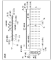
- FIG. 11 is a diagram schematically illustrating a state where the diaper 1 according to the second embodiment is expanded and extended.
- A) of FIG. 11 has shown typically the internal structure at the time of seeing the diaper 1 of the state expand
- B) of FIG. 11 has shown typically the top view of the diaper 1 of the state expand
- the longitudinal end portion of the absorbent body 8 is in contact with the first contraction portion S1.
- the longitudinal end portion of the absorbent body 8 extends to the end portion of the first contraction portion S1.
- the first contraction portion S1 is provided in the waist first region RW1 adjacent to the waist opening edges 4F9 and 4R9 and extends along the waistline direction. 4F1 and 4R1 are included, and the trunk opening is contracted in the trunk circumference direction.
- the second contraction portion S2 includes second thread rubbers 4F2 and 4R2 provided in the waist second region RW2 adjacent to the crotch region 1B side with respect to the first contraction portion S1 and extending along the waistline direction.
- the trunk opening is contracted in the trunk circumference direction.
- the range extended in the longitudinal direction of the diaper 1 is 15 mm, and the space
- a sheet member (for example, a back sheet 7) may be disposed between or in contact with the absorber 8 and the second rubber threads 4F2 and 4R2.
- Example 3 shows the results of the breathability quantitative test.
- the column “Measurement Position” indicates measurement positions A to E (see FIG. 8) similar to those of the first embodiment, and the rows of measurement positions A to E indicate the wind speed (m / s) at each measurement position. Indicates.
- the comparative example 1 and Example 4 produced the diaper of three sizes, M size, L size, and Big size.
- Example 4 As shown in Table 6, at the measurement position A, the wind speed was significantly increased in Example 4 (0.24 m / s) than in Comparative Example 1 (0.02 m / s). . On the other hand, no significant difference was observed between Example 4 and Comparative Example 1 for measurement positions B to E. Regarding the measurement position A, it is considered that the flow of air leaking outside from the gap between the skin of the waist gather G2 and the dummy doll becomes dominant. Therefore, it can be said that the air permeability of the waist gather G2 is significantly improved in Example 4 in which the wind speed at the measurement position A is remarkably increased as compared with Comparative Example 1.
- the number of sheet members that form the second contraction portion S2 is made larger than that of the sheet members that form the first contraction portion S1.
- the first contraction portion S1 is formed by a total of three sheet members including the cover sheets 4F and 4R, the folded portions 4F5 and 4R5, and the air passage formation sheets 11F and 11R.
- the second contraction part S2 includes the cover sheets 4F and 4R, the inner cover sheets 5F and 5R, the pad cover sheet 6, the back sheet 7, the center sheet 9, the folded parts 4F5 and 4R5, and the air passage forming sheet 11F. , 11R and a total of seven sheet members.
- the second contraction part S ⁇ b> 2 includes the absorber 8. For this reason, 2nd contraction part S2 is larger in bending resistance than 1st contraction part S1.
- the first contraction portion S1 guarantees a moisture discharge function for discharging the moisture in the internal space of the diaper 1 to the outside and a function for easily expanding the trunk opening 2T.
- the 2nd contraction part S2 of waist gathers G2 raises the contraction force in the circumference direction of the waist compared with the 1st contraction part S1, and the position maintenance function (displacement suppression) which controls slippage at the time of wearing of the diaper 1 Function).
- the second contraction part S2 more rigid than the first contraction part S1, the first and second flanges 41 and 42 of the cover sheets 4F and 4R and the air passage forming sheets 11F and 11R shown in FIG.
- the first ridge 113 and the second ridge 114 can be enlarged, and thus the first ventilation path 111 and the second ventilation path 112 can be enlarged.
- Example 4 a diaper corresponding to an example of the diaper 1 of the second embodiment and a diaper corresponding to the diaper 101 of the comparative example in the first embodiment were prepared, and the diaper slippage suppressing function was evaluated.
- a prototype diaper corresponding to an example of the diaper 1 of Embodiment 2 is hereinafter referred to as “Example 4”.
- a comparative diaper corresponding to the diaper 101 of the comparative example is hereinafter referred to as “comparative example 1”. Also in Example 4 and Comparative Example 1, baby diapers were prepared.
- Example 4 “Loika HS 470 dtex” is used as the thread rubber corresponding to the first thread rubber 4F1, 4R1, and the second thread rubber 4F2, 4R2, the third thread rubber. “Loika CR 470 dtex” is used as a rubber thread corresponding to 4F3, 4R3.
- the draft ratio of the thread rubber corresponding to the first thread rubbers 4F1 and 4R1 is 330% for the M size and 345% for the L size.
- Comparative Example 1 the draft rate of the thread rubber corresponding to the first thread rubbers 4F1 and 4R1 is 315% regardless of the size.
- Table 7 summarizes the distance between the rubber thread in the first contraction part and the distance between the absorber 8 and the first contraction part in the second contraction part in Comparative Example 1 and Example 4.
- Example 4 the rigidity of the site
- the stiffness corresponding to the first contraction portion S1 was 61 mmN
- the stiffness corresponding to the second contraction portion S2 was 112 mmN.
- the bending resistance indicates that the smaller the numerical value, the easier it is to bend, and the second contraction part of Example 4 is less likely to bend than the first contraction part, and the wrinkles are large.
- the number of folds As for the number of folds, the number of folds and the average heel height were measured in a stretched state with the center of the second rubber threads 4F2 and 4R2 stretched to cut a width of 5 cm. In Comparative Example 1, the number was 9 (average ridge height 1.3 mm), while in Example 4, the number was 6 (average ridge height 2 mm). Comparing the cross-sectional area of the fold which is an index of permeability, with respect to Comparative Example 1 In 16.25 mm 2, Example 4 in 25 mm 2, and the embodiment 4 is approximately 1.5 times the cross-sectional area than Comparative Example 1 improves.
- Example 4 the widening strength of the portions corresponding to the first contraction part S1 and the second contraction part S2 was measured.
- Example 4 and Comparative Example 1 The widening strength test for Example 4 and Comparative Example 1 will be described.
- the widening strength was measured in a range in which the first contracted portion and the second contracted portion in the waist gather when the trunk opening undergoes widening deformation.
- the widening strength test was implemented about 3 types, Big size, L size, and M size, about Example 4 and Comparative Example 1, respectively.
- the M size second contraction part S2 was set to have an interval of 7 mm and 5 pieces
- the L size and Big size second thread rubbers were set to have an interval of 5 mm and 4 pieces.
- the widening strength of the M-size test piece was calculated as an average value of measurement results measured when the distance between the upper and lower chuck portions was 30 cm, 44 cm, and 58 cm. Further, the widening strength of the L-size and Big-size test pieces was calculated as an average value of measurement results measured when the distance between the upper and lower chuck portions was 38 cm, 48 cm, and 62 cm.
- Table 8 shows the results of the widening strength test for Example 4 and Comparative Example 1.
- the average value of the widening strength at the widening width of 44 cm of each test piece prepared in Comparative Example 1 is 2.6 N for the M size and Big size, and 2.8 N for the L size in Example 4.
- the average value of the widening strength at the widening width of 44 cm of each of the prepared test pieces was 2.4 N for the M size and Big size, and 2.5 N for the L size.
- the widening strength of the second contraction portion is 1.4 N or more in the M size and the Big size 3 .4N or less, L size is preferably 1.5N or more and 3.5N or less, and the widening strength of Example 4 is included in the above-mentioned suitability range. It was confirmed that it could not fully perform.
- Embodiment 3 Next, a diaper according to Embodiment 3 will be described.
- the diaper 1 which concerns on this embodiment has the same component as the diaper which concerns on Embodiment 1 mentioned above.
- the same components as those in the first embodiment described above are denoted by the same reference numerals, and detailed description thereof is omitted.
- the diaper 1 has a space between the center sheet 9 (an example of a “skin-side sheet member”) in the region overlapping the vicinity of the longitudinal end of the absorbent body 8 and the wearer's skin when worn. It is characterized by being formed.
- the center sheet 9 is a sheet member that is laminated on the absorbent body 8 to form a skin facing surface.
- FIG. 12 is a diagram schematically illustrating a state where the diaper 1 according to the third embodiment is expanded and extended.
- A) of FIG. 12 has shown typically the internal structure at the time of seeing the diaper 1 of the state expand
- B) of FIG. 12 has shown typically the top view of the diaper 1 of the state expand
- the diaper 1 has fold lines 50F and 50R that are convex toward the end portion in a region overlapping the vicinity of the end portion in the longitudinal direction of the absorbent body 8 when viewed in plan.
- the folding lines 50F and 50R may be formed on the absorbent body 8 or may be formed on the center sheet 9.
- the folding lines 50 ⁇ / b> F and 50 ⁇ / b> R may be compressed grooves formed in the absorber 8 or the center sheet 9.
- the folding lines 50F and 50R may be formed by embossing (3D embossing) in which the center sheet 9 is formed by two sheet members and is formed by an adhesion portion of the two sheet members.
- the diaper 1 can form a space between the center sheet 9 and the wearer's skin by bending the end portions in the longitudinal direction of the absorbent body 8 at the time of wearing by the folding lines 50F and 50R.
- the diaper 1 can flow the moisture from the absorber 8 that has absorbed the liquid to the first ventilation path 111 and the second ventilation path 112 through the space, and efficiently discharge the moisture to the outside.
- the diaper 1 which concerns on this embodiment has favorable air permeability.
- the space may be formed by adhering stretched rubber thread to the longitudinal end of the absorbent body 8.
- Patent No. 1 various proposals have been made to improve the breathability of the absorbent article in order to discharge moisture that remains in the internal space of the absorbent article to the outside when the absorbent article is worn.
- Patent No. 1 See Japanese Patent No. 5573806.
- a disposable diaper is known in which an outer layer sheet and an inner layer sheet are contracted in the circumferential direction by an elastic member to form a heel around the waist, and moisture is discharged to the outside through a gap between the heel and the wearer's skin. ing.
- an object of the present embodiment is to provide an absorbent article having better air permeability than conventional ones.
- the absorbent article according to the present embodiment is located between the front body region covering the wearer's abdomen, the back body region covering the wearer's back, and the front body region and the back body region.
- the absorbent article in which the crotch region where the absorbent body is arranged is continuously provided, in the front opening region and the back body region, at least the wearer's torso through which the wearer's torso can be inserted
- a plurality of elastic members extending along the waist direction from a portion corresponding to the hip bone, and a lower shrinkage portion of the trunk opening that shrinks the trunk opening in the waist direction, an opening edge of the trunk opening, and the trunk opening
- a trunk opening upper contraction section that includes a plurality of elastic members extending along the waistline direction between the lower contraction section and a trunk opening upper contraction section that contracts the trunk opening in the trunk circumference direction. The space between the plurality of elastic members Greater than the spacing between the plurality of elastic members having the upper constriction.
- 6.5 mm or more and 12 mm or less may be sufficient as the space
- the trunk opening lower contraction part may be provided in a region including a range of 20 mm or more and 40 mm or less from the edge of the opening.
- the airflow path forming sheet is further provided so as to cover the skin facing surface in the upper shrinkage portion of the trunk opening and the lower shrinkage portion of the trunk opening.
- a plurality of joints are intermittently provided along the joint, and the non-joint region located between the joints is bent and deformed into a corrugated shape by contraction of the upper contraction part of the trunk opening and the contraction part of the lower part of the trunk opening. By doing so, you may form a ventilation path.
- an opening end that contracts the trunk opening in the waist direction including a plurality of elastic members extending in the waist direction along the opening edge between the opening edge and the trunk opening upper contraction portion
- interval of the some expansion-contraction member which further has an edge side contraction part and which the opening part edge side contraction part has may be larger than the space
- a cover sheet that includes an expansion / contraction member included in the upper contraction portion of the trunk opening in a portion forming the trunk opening, and the cover sheet is folded at the edge portion of the opening, and is folded at the fold of the folded portion. You may have a continuous ventilation hole which penetrates a cover sheet.
- Embodiment 4 of the present invention will be described.
- Embodiment shown below is an example of embodiment of this invention, and does not limit the technical scope of this invention to the following aspects.
- FIG. 13 is a perspective view of a pants-type disposable diaper (hereinafter simply referred to as “diaper”) 1 according to the fourth embodiment.
- FIG. 14 is an exploded perspective view of the diaper 1 according to the fourth embodiment.
- FIG. 15 is the figure which showed typically the state which expand
- (A) of FIG. 15 has shown typically the internal structure at the time of seeing the diaper 1 at the time of expansion
- (B) of FIG. 15 has shown typically the planar structure of the diaper 1 at the time of expansion
- the direction used in this specification shall mean the direction which corresponds to the wearer's front and rear, right and left in the state where diaper 1 was worn by the wearer.
- the left-right direction means a direction that matches the left and right of the wearer when the diaper 1 is worn by the wearer.
- the “front body region” of the diaper 1 means a portion that covers the abdomen (front of the body) of the wearer when the diaper 1 is worn on the wearer.
- the “inseam area” of the diaper 1 means a portion that covers the inseam of the wearer when the diaper 1 is worn on the wearer.
- the “rear body region” of the diaper 1 means a portion that covers the wearer's back (back of the body) when the diaper 1 is worn on the wearer.
- the “longitudinal direction” means a direction connecting the front body region and the back body region of the diaper 1. That is, the longitudinal direction of the diaper 1 coincides with the continuous direction in which the front body region, the crotch region, and the back body region are continuously provided.
- the “width direction” means a direction orthogonal to the longitudinal direction of the diaper 1.
- a pants-type disposable diaper having a tubular structure having an opening into which the wearer's abdomen enters and a pair of left and right openings through which the wearer's left lower limb and right lower limb are inserted
- the “absorbent article” in this specification is not limited to a pants-type disposable diaper.
- the “absorbent article” includes, for example, a tape that is fixed near one end of a sheet-like member that covers the wearer's crotch (pubic region) from the front body region to the back body region, and the other end of the sheet-like member.
- Various types of absorbent articles that can wrap the abdominal circumference and crotch such as a tape-type disposable diaper that forms a cylindrical structure by being attached in the vicinity of the part, are included.
- the diaper 1 includes a crotch region 1B that covers the crotch (pubic region) of the wearer, a front body region 1F that covers the abdomen of the wearer, and a back body that covers the back of the wearer. And a region 1R.
- the crotch region 1B is located between the front body region 1F and the back body region 1R and is connected to the front body region 1F and the back body region 1R, and the crotch region 1B absorbs and holds liquid.
- a main body 15 (absorber 8) is provided.
- the diaper 1 in this embodiment is a pants-type disposable diaper
- the left side edge of the front body region 1F and the left side edge of the back body region 1R are joined together, and the right side edge of the front body region 1F and the back body region 1R
- the right edges are joined to each other, thereby assembling the state shown in FIG.
- a trunk opening (waist opening) 2T is formed by the upper edge of the front body region 1F and the upper edge of the rear body region 1R.
- a left lower limb opening 2L is formed on the left side of the crotch region 1B where the joining is not performed
- a right lower limb opening 2R is formed on the right side of the crotch region 1B.
- the left lower limb opening 2L and the right lower limb opening 2R are openings through which the wearer's legs are inserted when the diaper 1 is worn.
- the wearer's left lower limb is inserted into the left lower limb opening 2L
- the wearer's right lower limb is inserted into the right lower limb opening 2R
- the wearer's torso enters (passes through) the torso opening 2T.
- the front body region 1F contacts the wearer's abdomen
- the back body region 1R contacts the wearer's back side
- the crotch region 1B is applied to the wearer's crotch
- the left lower limb opening 2L and right lower limb opening 2R are fixed to the wearer's body in a state of surrounding the wearer's thigh. Since the diaper 1 is fixed to the wearer's body in this manner, it is possible to walk while the diaper 1 is worn.
- an absorbent body 8 that can absorb and hold liquid is mainly disposed around the crotch region 1B. Further, in the diaper 1, in order to suppress the formation of a gap as a liquid outflow path between the diaper 1 and the wearer's skin, the left lower limb opening 2 ⁇ / b> L, the right lower limb opening 2 ⁇ / b> R, the torso opening
- the part 2T is provided with a three-dimensional gather G1L, a three-dimensional gather G1R, and a waist gather G2, respectively.
- the three-dimensional gathers G1L and G1R and the waist gather G2 are configured so as to be in close contact with the wearer's skin by the elastic force of the rubber thread, so that the excretory fluid discharged from the wearer is not leaked from the diaper 1. It can be made to absorb in the absorption part main body 15 (absorber 8).
- the diaper 1 has cover sheets 4F and 4R and a pad cover sheet 6 that form an outer surface in a state worn on the wearer.
- the cover sheet 4F is a sheet member that mainly forms the outer surface of the front body region 1F of the diaper 1.
- the pad cover sheet 6 is a sheet member for mainly forming the outer surface of the crotch region 1B of the diaper 1.
- the cover sheet 4R is a sheet member for mainly forming the outer surface of the rear body region 1R of the diaper 1.
- the cover sheets 4F and 4R and the pad cover sheet 6 are provided, for example, for reinforcing the outer surface of the diaper 1 and improving the touch.
- the cover sheets 4F and 4R and the pad cover sheet 6 can be formed of a nonwoven fabric made of, for example, a liquid-impermeable thermoplastic resin in order to suppress leakage of excrement.
- the liquid-impermeable thermoplastic resin include polyethylene (PE) and polypropylene (PP).
- PE polyethylene
- PP polypropylene
- the liquid-impermeable sheet may have a large number of fine pores of about 0.1 to several ⁇ m so that the liquid-impermeable and moisture-permeable properties are exhibited.
- the diaper 1 has the inner cover sheet 5F laminated
- the “skin facing surface” means a surface facing the wearer's skin when the wearer wears the diaper 1.
- the inner cover sheet 5F is a sheet member that is bonded to the cover sheet 4F in a state where a rubber thread that is a linear elastic member is sandwiched between the cover sheet 4F and the interlayer.
- the inner cover sheet 5F is a sheet member having a shape and a size corresponding to a portion of the cover sheet 4F excluding the folded portion 4F5 described later and the waist first region RW1 in the exterior cover portion 4F10.
- the inner cover sheet 5R is a sheet member that is bonded to the cover sheet 4F in a state in which a thread rubber that is a linear elastic member is sandwiched between the layers with the cover sheet 4R.
- the inner cover sheet 5R is a sheet member having a shape and a size corresponding to a portion of the cover sheet 4R excluding the folded portion 4R5 described later and the waist first region RW1 in the exterior cover portion 4R10.
- the diaper 1 of the present embodiment includes an absorbent body 15.
- the absorbent main body 15 is held in a state of being bridged between the front body region 1F and the back body region 1R, and is placed on the inseam of the wearer when the diaper 1 is worn, and liquid such as urine excreted by the wearer. Absorb and hold.
- the absorbent body 15 includes a pad cover sheet 6, a back sheet 7, an absorbent body 8, a center sheet 9, side sheets 10 ⁇ / b> L, 10 ⁇ / b> R, and the like, and is integrally formed by these. .
- the back sheet 7, the absorber 8, and the center sheet 9 are laminated in order on the skin facing surface of the pad cover sheet 6.
- the pad cover sheet 6 has a length in the longitudinal direction that reaches from the wearer's front body to the back body through the crotch, and has a rectangular plane having a predetermined lateral width in the width direction orthogonal to the longitudinal direction. It is a sheet member to have.
- the back sheet 7, the absorbent body 8, and the center sheet 9 are all sheet members having a rectangular plane like the pad cover sheet 6, and the pad cover is in a state where the longitudinal direction coincides with the longitudinal direction of the pad cover sheet 6.
- the sheets 6 are laminated in this order.
- the absorber 8 is a member that absorbs liquid such as urine and holds the absorbed liquid.
- the absorber 8 is disposed between the liquid-impermeable back sheet 7 and the liquid-permeable center sheet 9.
- Absorbent body 8 has water in gaps between short fibers of cellulose fibers such as pulp fibers, rayon fibers, or cotton fibers, or short fibers obtained by subjecting synthetic fibers such as polyethylene, polypropylene, or polyethylene terephthalate to hydrophilic treatment. It may have a structure in which a granular absorbent resin such as a hydrophilic superabsorbent polymer having a cross-linked structure capable of absorbing and retaining water is retained.
- the absorber 8 may have a single layer structure made of one mat or a laminated structure in which a plurality of mats are stacked. Moreover, the absorber 8 can employ
- the center sheet 9 is a sheet member that directly contacts the skin of the wearer's crotch and allows liquid such as urine to pass through the absorbent body 8, and is laminated so as to cover the water absorption surface of the absorbent body 8.
- the center sheet 9 in the present embodiment is formed of a highly permeable liquid permeable material. Examples of the liquid permeable material forming the center sheet 9 include a woven fabric, a nonwoven fabric, and a porous film.
- the center sheet 9 may have hydrophilicity.
- the back sheet 7 is a sheet member for suppressing the liquid that has passed through the center sheet 9 and absorbed by the absorber 8 from leaking to the outside of the diaper 1. For this reason, the back sheet 7 is formed of a liquid-impermeable material.
- the liquid impermeable material forming the back sheet 7 include a liquid impermeable film made of polyethylene resin.
- the backsheet 7 may be formed of a microporous polyethylene film in which a large number of micropores are formed in order to ensure air permeability.
- the pad cover sheet 6 is a member for reinforcing the back sheet 7 and improving the touch thereof, and is bonded to the back sheet 7.
- Examples of the material forming the pad cover sheet 6 include woven fabric and non-woven fabric.
- the pad cover sheet 6 may be a nonwoven fabric or a wet nonwoven fabric made of a thermoplastic resin such as polyethylene, polypropylene, or polyester.
- the side sheets 10L and 10R in the absorber main body 15 are elongated strip-shaped members for forming the above-described three-dimensional gathers G1L and G1R.
- the side sheets 10 ⁇ / b> L and 10 ⁇ / b> R are extended along the long side portion of the center sheet 9. Further, thread rubbers 10L1 and 10R1 are bonded to the side sheets 10L and 10R along the longitudinal direction.
- the left side edge 4F7 of the cover sheet 4F forming the left side edge of the front body region 1F and the left side edge 4R7 of the cover sheet 4R forming the left side edge of the back body region 1R are joined together, and the right side edge of the front body region 1F is joined When the diaper 1 shown in FIG.
- a method for joining the side edges of the cover sheets 4F and 4R is not particularly limited, and examples thereof include heat sealing, high frequency sealing, and ultrasonic sealing.
- the absorbent body 15 extends from the front body region 1F to the back body region 1R.
- the cover sheet 4F has a folded portion 4F5 formed by folding the front end side inward with the fold line 4F6 as a boundary.
- a portion of the cover sheet 4F excluding the folded portion 4F5 is referred to as an exterior cover portion 4F10.
- the exterior cover portion 4F10 of the cover sheet 4F forms the outer surface of the diaper 1.
- the fold line 4F6 of the cover sheet 4F forms a trunk opening edge 4F9 of the trunk opening 2T in a state where the diaper 1 is assembled.
- the folded-back portion 4F5 in the cover sheet 4F has an extended first thread rubber 4F1 disposed between the outer cover portion 4F10 and the interlayer. Further, the front end side of the folded portion 4F5 in the cover sheet 4F is a state in which one end side in the longitudinal direction of the inner cover sheet 5F, the pad cover sheet 6, the back sheet 7 and the absorbent body 8 is sandwiched between the layers with the exterior cover portion 4F10. Thus, the absorbent body 8 is bonded in a state of being overlapped with one end portion.
- the aspect at the time of expressing that one member and another member are overlapped is not limited to an aspect in which the members overlap each other in a state of being in full contact with each other. It is a concept including a mode in which a part of the other member and the whole of the other member overlap, or a mode in which a part of one member and the other member overlap each other.
- the second thread rubber 4F2, the third thread rubber 4F3, and the fourth thread rubber 4F4 are arranged from the folding line 4F6 side. However, they are arranged in this order, and are bonded in a state of being sandwiched between the outer cover portion 4F10 and the inner cover sheet 5F.
- a plurality of first thread rubbers 4F1 to 4F thread rubbers 4F4 in the cover sheet 4F are arranged in parallel, each along the width direction (the waistline direction) of the cover sheet 4F. It is extended.
- the cover sheet 4R also has a folded portion 4R5 formed by folding the front end side inward with the fold line 4R6 as a boundary.
- a portion of the cover sheet 4R excluding the folded portion 4R5 is referred to as an exterior cover portion 4R10.
- the exterior cover portion 4R10 of the cover sheet 4R forms the outer surface of the diaper 1.
- the folding line 4R6 of the cover sheet 4R forms a trunk opening edge 4R9 of the trunk opening 2T in a state where the diaper 1 is assembled.
- the extended first thread rubber 4R1 is disposed between the outer cover portion 4R10 and the interlayer.
- the other end side of the inner cover sheet 5R, the pad cover sheet 6, the back sheet 7, and the absorbent body 8 in the longitudinal direction is sandwiched between the outer cover part 4R10 and the front end side of the folded portion 4R5 in the cover sheet 4R. In the state, it is bonded in a state of being overlapped with the other end portion of the absorber 8.
- the second thread rubber 4R2, the third thread rubber 4F3, and the fourth thread rubber 4R4 are arranged from the folding line 4R6 side. Are arranged in this order, and are bonded in a state of being sandwiched between the outer cover portion 4R10 and the inner cover sheet 5R.
- the first thread rubber 4R1 to the fourth thread rubber 4R4 in the cover sheet 4R are each arranged in parallel, and all are along the width direction (the waistline direction) of the cover sheet 4R. It is extended.
- the waist area RW of the diaper 1 is an area where the waist gathers G2 are formed in the vicinity of the trunk opening edges 4F9 and 4R9 forming the trunk opening 2T.
- a region where the first rubber threads 4F1 and 4R1 are disposed is referred to as a “waist first region RW1” (first region), and a region where the second rubber rubbers 4F2 and 4R2 are disposed. Is referred to as “waist second region RW2” (second region).
- an area where the third thread rubbers 4F3 and 4R3 and the fourth thread rubbers 4F4 and 4R4 are arranged is referred to as a “tammy area RT”.
- the Tammy region RT is a region located below the waist region RW.
- the region where the third rubber threads 4F3, 4R3 are disposed is referred to as “tammy first region RT1”, and the region where the fourth rubber rubbers 4F4, 4R4 are disposed is referred to as “tammy second region RT2.
- the first rubber threads 4F1 and 4R1 in the waist first region RW1 are applied with an adhesive in an expanded state in the assembly process of the diaper 1, for example, and then the exterior cover portions 4F10 and 4R10 and the folded portions 4F5 are applied. By being sandwiched between 4R5, it adheres between these layers.
- the second thread rubbers 4F2 and 4R2 in the waist second region RW2 and the third thread rubbers 4F3 and 4R3 and the fourth thread rubbers 4F4 and 4R4 in the tammy region RT are expanded in the assembly process of the diaper 1, for example. After the adhesive is applied in this state, it is bonded between the outer cover portions 4F10, 4R10 of the cover sheets 4F, 4R and the inner cover sheets 5F, 5R by being sandwiched between them.
- the first rubber threads 4F1 and 4R1 in the waist first region RW1 that are sandwiched and bonded between the outer cover portions 4F10 and 4R10 and the inner cover sheets 5F and 5R in the cover sheets 4F and 4R are contracted.
- the portion corresponding to the waist first region RW1 of the exterior cover portions 4F10, 4R10 and the folded portions 4F5, 4R5 is continuously bent in a pleated shape to follow the waist first region RW1 in the waistline direction.
- a first contraction portion S1 that contracts is formed.
- the waist second region RW2 when the second rubber threads 4F2 and 4R2 which are sandwiched and bonded in an extended state between the outer cover portions 4F10 and 4R10 and the inner cover sheets 5F and 5R are contracted, the exterior is followed accordingly.
- the cover portions 4F10, 4R10 and the inner cover sheets 5F, 5R the second contraction that contracts the waist second region RW2 in the waistline direction by continuously bending the portion corresponding to the waist second region RW2 in a pleated shape.
- a portion S2 (which is an example of a “body opening upper contraction portion” in the present application) is formed.
- the waist gather G2 is formed mainly by the first contraction portion S1 formed in the waist first region RW1 and the second contraction portion S2 formed in the waist second region RW2.
- the waist gather G2 improves the fit of the diaper 1 around the wearer's waist by the contraction force of the first thread rubber 4F1, 4R1 and the second thread rubber 4F2, 4R2.
- a plurality of first rubber threads 4F1 and 4R1 are arranged in parallel with each other at a constant interval A1.
- a plurality of second rubber threads 4F2 and 4R2 are provided in the second contraction portion S2 of the waist gather G2 in parallel with each other and at a constant interval A2.
- interval of thread rubber here means the dimension which spaces apart adjacent thread rubber in the longitudinal direction (direction which connects a body part area
- the first rubber bands 4F1 and 4R1 in the first waist region RW1 and the second rubber bands 4F2 and 4R2 in the second waist region RW2 extend over the entire width section of the cover sheets 4F and 4R. ing. Therefore, after the diaper 1 is completed, the first rubber threads 4F1 and 4R1 and the second rubber threads 4F2 and 4R2 form a substantially annular elastic member that circulates along the trunk opening 2T. In other words, after the diaper 1 is completed, the waist gather G2 (the first contraction part S1 and the second contraction part S2) is formed over the entire circumference in the waistline direction.
- the third rubber threads 4F3 and 4R3 which are sandwiched and bonded in an extended state between the outer cover portions 4F10 and 4R10 and the inner cover sheets 5F and 5R in the cover sheets 4F and 4R are contracted.
- the portion corresponding to the first tammy region RT1 is continuously bent in a pleated shape, so that A third contraction portion S3 (which is an example of “the trunk opening lower contraction portion” in the present application) that contracts one region RT1 in the waistline direction is formed.
- 3rd contraction part S3 is an area
- the fourth thread rubbers 4F4 and 4R4 which are sandwiched and bonded in an extended state between the outer cover portions 4F10 and 4R10 and the inner cover sheets 5F and 5R in the cover sheets 4F and 4R are also provided.
- the portion corresponding to the Tammy second region RT2 of the exterior cover portions 4F10, 4R10 and the inner cover sheets 5F, 5R in the cover sheets 4F, 4R continuously bends in a pleated shape.
- a fourth contraction portion S4 that contracts the Tammy second region RT2 in the waistline direction is formed.
- the Tammy gather G3 is formed mainly by the third contraction portion S3 formed in the Tammy first region RT1 and the fourth contraction portion S4 formed in the Tammy second region RT2.
- the Tammy Gather G3 improves the fit of the diaper 1 around the lower abdomen of the wearer, for example, by the contraction force of the third rubber threads 4F3 and 4R3 and the fourth rubber threads 4F4 and 4R4.
- the third thread rubbers 4F3 and 4R3 arranged in the third contraction part S3 of the Tammy Gather G3 are provided in parallel with each other and with a certain distance A3.
- the fourth rubber threads 4F4 and 4R4 disposed in the fourth contraction portion S4 of the Tammy gather G3 are also provided in parallel with each other and with a constant interval A4.
- the distance A3 between the third thread rubbers 4F3 and 4R3 in the third contraction part S3 of the Tammy gather G3 is greater than the distance A2 between the second thread rubbers 4F2 and 4R2 in the second contraction part S2 of the waist gather G2.
- the second contraction portion S2 is relatively easy to expand.
- the thread rubbers 4F1, 4R1, 4F2, 4R2, 4F3, 4R3, 4F4, 4R4 are attached to the cover sheets 4F, 4R.
- “linear” represents an elongated shape extending in a specific direction, and is a concept including a strip shape and a strip shape.
- natural rubber, synthetic rubber, etc. can be illustrated as a material of thread rubber, However, It is not limited to a specific material.
- the diaper 1 includes the folded portions 4F5 and 4R5 in the cover sheets 4F and 4R, the pad cover sheet 6 in the absorbent body 15 and the longitudinal end regions of the center sheet 9 and the like.
- Ventilation path forming sheets 11F and 11R are provided so as to be stacked on the folded portions 4F5 and 4R5.
- the ventilation path forming sheets 11F and 11R form skin contact surfaces in the waist gather G2 and the tammy gather G3 of the diaper 1.
- the “skin contact surface” means a surface that directly contacts the wearer's skin when the diaper 1 is worn, that is, the innermost surface of the diaper 1.
- FIG. 16 is a diagram illustrating an installation mode of the air passage forming sheets 11F and 11R of the diaper 1 according to the embodiment.
- (A) of FIG. 16 is a figure which shows the state which looked at 1st contraction part S1 of waist gathers G2 from the internal space side of the diaper 1.
- FIG. Moreover, (B) of FIG. 16 is a figure which shows typically the internal structure in 1st contraction part S1 of the waist gather G2 at the time of seeing from the side of the diaper 1.
- FIG. Moreover, (C) of FIG. 16 is a figure which shows the state which looked at 1st contraction part S1 of waist gathers G2 from the upper direction (namely, A arrow direction of (B)) of the diaper 1.
- FIG. 16A and 16C show a state before the first contraction portion S1 in the waist gather G2 contracts for convenience.
- (D) of FIG. 16 is a figure which shows the state which looked at 1st contraction part S1 of waist gathers G2 after shrinkage
- the ventilation path forming sheets 11F and 11R are disposed at sites corresponding to at least the first contraction part S1, the second contraction part S2, and the third contraction part S3, and the pad cover is provided via a joint part indicated by reference numeral S.
- the sheet 6 is joined to the end region in the longitudinal direction and the folded portions 4F5, 4R5 and the like.
- FIG. 17 is a view showing a portion of the joining portion S joining the air passage forming sheets 11F and 11R.
- the folded portions 4F5 and 4R5 of the cover sheets 4F and 4R formed of the thermoplastic resin and the air passage forming sheets 11F and 11R superimposed on the pad cover sheet 6 are joined by ultrasonic welding, thereby joining. Part S is formed. As shown in FIG. 16A and FIG.
- a plurality of joints S are intermittent along the longitudinal direction perpendicular to the trunk direction (width direction) from the trunk opening edges 4F9 and 4R9 of the cover sheets 4F and 4R.
- the linear joint SL extending in the longitudinal direction of the diaper 1 is formed.
- one linear joint portion SL is formed as an assembly of a plurality of joint portions S that are intermittently arranged along the longitudinal direction of the diaper 1.
- “intermittently” means an aspect of being discontinuously or intermittently arranged.
- a plurality of linear joints SL are intermittently provided along the waistline direction (width direction) of the cover sheets 4F and 4R in the first contraction part S1 of the waist gather G2.
- the linear joints SL are provided in parallel to each other, and the intervals between the linear joints SL are set to be alternately large and small.
- the linear joints SL are intermittently arranged in such a manner that double lines formed by a set of linear joints SL are arranged at equal intervals in the waistline direction (width direction).
- FIG. 15 (A) the range which the linear junction part SL extends in the longitudinal direction of the diaper 1 is shown by hatching. As illustrated, the linear joint portion SL extends across the waist first region RW1 where the first contraction portion S1 is formed and the waist second region RW2 where the second contraction portion S2 is formed.
- the ultrasonic joining of the air passage forming sheets 11F and 11R in the first contraction part S1 and the second contraction part S2 of the waist gather G2 and the third contraction part S3 of the Tammy gather G3 is performed by the first thread rubber 4F1 and 4R1 of the waist gather G2. And the second rubber threads 4F2 and 4R2, and the third rubber threads 4F3 and 4R3 and the fourth rubber threads 4F4 and 4R4 of Tammy Gather G3 are in an extended state. Then, after the joining of the air passage forming sheets 11F and 11R in the first contraction part S1 and the second contraction part S2 of the waist gather G2 and the third contraction part S3 of the Tammy gather G3 is completed, the sheet is sandwiched and fixed between the sheet layers.
- the extended states of the first thread rubbers 4F1 and 4R1, the second thread rubbers 4F2 and 4R2, the third thread rubbers 4F3 and 4R3, and the fourth thread rubbers 4F4 and 4R4 are released.
- the waist gather G2 and the Tammy gather G3 contract, and the interval between the linear joint portions SL in the air passage forming sheets 11F and 11R is narrowed.
- the non-joining regions 110 located between the linear joining portions SL are separated, and as shown in FIG. 16D, the folded portions 4F5, 4R5 and the like and the air passage forming sheets 11F, 11R.
- a first air passage 111 surrounded by the non-joining region 110 is formed.
- the 2nd ventilation path 112 is formed in the skin contact surface 11a side of the ventilation path formation sheets 11F and 11R.
- a two-dot chain line indicated by a symbol SS in FIG. 16D indicates a skin surface that comes into contact with the air passage forming sheets 11F and 11R as a virtual line when the diaper 1 is worn by the wearer.
- the second air passage 112 is formed as a gap formed between the skin contact surface 11a of the air passage forming sheets 11F and 11R and the skin of the wearer when the diaper 1 is worn by the wearer. Moisture in the inner space of the diaper 1 passes through the first air passage 111 and the second air passage 112 formed in the first contraction part S1 and the second contraction part S2 of the waist gather G2, and the third contraction part S3 of the Tammy gather G3. It can be discharged to the outside.
- the 1st ventilation path 111 is a ventilation path through which the moisture which permeate
- the second ventilation path 112 is a ventilation path that directly communicates the internal space and the external space of the diaper 1, and can discharge the moisture in the diaper 1 more smoothly.
- the relatively large first collar 41 and the relatively small second collar that form the first contraction part S1. 42 are alternately formed.
- the relatively large first ridges 113 and the relatively small second ridges 114 are alternately formed in the air passage forming sheets 11F and 11R that are bent and deformed in the waveform. This is due to the fact that the intervals between the linear joint portions SL are set to be alternately large and small. That is, a large first rod 41, 113 is formed by a set of linear joints SL having a large interval, and a small second rod 42, 114 is formed by a set of linear junctions SL having a small interval.
- the first ridge 113 of the airflow passage forming sheets 11F and 11R that are bent and deformed in a waveform is to cooperate with the first ridge 41 that forms the first contraction portion S1 in order to secure a large first airflow passage 111.
- the second ridge 114 of the ventilation path forming sheets 11F and 11R cooperates with the second ridge 42 forming the first contraction portion S1 to form the first ventilation path 111 and in the waistline direction (width direction). This contributes to properly separating the adjacent first flanges 113 and securing a ventilation cross section of the second ventilation path 112.
- the flute structure formed by the airflow passage forming sheets 11F and 11R that deform into a wave shape following the contraction of the waist gathers G2 and Tammy gathers G3 has the first contraction part S1 and the second contraction of the waist gathers G2.
- the moisture in the diaper 1 can be efficiently discharged to the outside through the first ventilation path 111 and the second ventilation path 112. it can.
- the linear junction part SL is formed as an aggregate
- the adjacent first ventilation paths 111 are communicated with each other. Therefore, it is possible to improve the air permeability between the adjacent first air passages 111 and make it difficult for the wearer to receive a local feeling of stuffiness.
- the ventilation path forming sheets 11F and 11R in the present embodiment are provided with a large number of fine ventilation holes 11F1 and 11R1 for ventilation.
- the air hole means an opening that allows communication between the space on one side of the sheet and the space on the other side, and the shape thereof is not particularly limited. Therefore, as the vent holes 11F1 and 11R1, for example, openings having a shape such as a circle, an ellipse, and a polygon (triangle, square, etc.) can be applied.
- the formation of the air holes 11F1, 11R1 in the air passage forming sheets 11F, 11R does not mean that the air passage forming sheets 11F, 11R are a material having no air permeability, and the air passage forming sheets 11F, 11R, 11R may be either a breathable material or a non-breathable material.
- the air passage forming sheets 11F and 11R are preferably made of a material having air permeability and liquid permeability, but may be a non-breathable material, for example.
- the size and the number of the vent holes 11F1 and 11R1 are not particularly limited. For example, if the opening area is 0.5 to 10 mm 2 , about 5 to 200 are preferably formed.
- the present inventors have determined that the third thread rubber 4F3 forming the third contraction part S3 is larger than the interval A2 between the second thread rubbers 4F2 and 4R2 forming the second contraction part S2.
- the third contraction S3 is guided to the wearer's hip bone so that the diaper 1 is in an appropriate wearing state, and the third contraction expands and contracts in accordance with the wearer's movement. It came to find that the pump effect accompanying the deformation
- the air passage forming sheets 11F and 11R are restrained by the third thread rubbers 4F3 and 4R3 as compared to the case where the distance A3 is set to a narrower distance.
- the first ventilation path 111 and the second ventilation path 112 become larger due to a decrease in the degree of restraint, and the pumping effect in the third contraction part S3 is increased.
- FIG. 18 is a diagram showing the magnitude of contraction force in each contraction part.
- the white arrow shown in FIG. 18 indicates the magnitude of the contractile force.
- the distance A3 between the third thread rubbers 4F3 and 4R3 forming the third contraction part S3 is larger than the distance A2 between the second thread rubbers 4F2 and 4R2 forming the second contraction part S2. large. Therefore, as for the diaper 1 of this embodiment, as FIG. 18 shows, the contraction force of 3rd contraction part S3 is weaker than the contraction force of 1st contraction part S1 and 2nd contraction part S2.
- And 3rd contraction part S3 is designed so that a wearer's hipbone may be contact
- the third contraction part S3 is a torso opening 2T so as to coincide with a range of 20 mm or more and 40 mm or less, which is a distance from the first joint and the second joint of a general adult index finger to the tip of the finger. It is provided in the area
- the torso opening 2T is used when the wearer wears it. Since the third contraction part S3 spreads most when it is expanded at the position, the second joint of the index finger of the person performing the wearing operation is applied to the vicinity of the opening edge of the trunk opening part 2T, and the first contraction part S1 and the first contraction part S1 A state in which the second contraction part S2 is located between the first joint and the second joint of the index finger and the tip of the index finger is caught by the third contraction part S3 that is easier to expand than the first contraction part S1 and the second contraction part S2. Become.
- the diaper 1 designed so that the third contraction portion S3 contacts the wearer's hipbone is attached to the wearer at an appropriate position.
- FIG. 19 is a diagram for explaining wrinkles formed in the second contraction part S2 of the waist gather G2 and the third contraction part S3 of the Tammy gather G3.
- the degree of restraint by the thread rubber increases as the distance between the thread rubbers becomes closer to the thread rubber. Accordingly, the first ridge 113 and the second ridge 114 of the air passage forming sheets 11F and 11R formed between the third rubber threads 4F3 and 4R3 are narrower than the distance A3 between the third rubber threads 4F3 and 4R3.
- the air passage forming sheets 11F and 11R formed between the second rubber threads 4F2 and 4R2 arranged at the interval A2 are more restrained than the first and second ridges 113 and 114.
- the wrinkle formed in the third contraction part S3 of Tammy Gather G3 is larger than the wrinkle formed in the second contraction part S2 of the waist gather G2.
- sizes of the 1st ventilation path 111 and the 2nd ventilation path 112 which are formed of the 1st collar 113 and the 2nd collar 114 in the part of Tammy gather G3 are other It becomes larger than the part.
- Tammy gather G3 is a part which expands-contracts by a wearer's operation
- the pump function is demonstrated by this, and the moisture in the diaper 1 is discharged
- the wearer's hipbone portion is the portion having the largest width around the wearer's waist, and is also a place where the surroundings of the wearer are in contact with each other and external pressure is easily applied. Therefore, Tammy Gather G3 corresponding to the hipbone portion Then, the pump effect by the 1st ventilation path 111 and the 2nd ventilation path 112 expanding and contracting with external pressure is also anticipated. Thereby, the interior space of the diaper 1 can be made into a more comfortable environment.
- the wrinkle formed in the part of Tammy Gather G3 is larger than the wrinkle formed in the 2nd contraction part S2 of West Gather G2, the wrinkle of the part of Tammy Gather G3 Is more conspicuous than the others, and the wearer can be made to naturally recognize Tammy Gather G3 so as to come into contact with the hip bone having the largest width around the waist of the wearer.
- the wrinkle formed in the portion of Tammy Gather G3 is larger than the wrinkle formed in the second contraction portion S2 of the waist gather G2, the portion of the Tammy Gather G3 tends to spread when the body opening 2T is widened. For this reason, when wearing the diaper 1, the diaper 1 is easily aligned naturally so that the portion of the Tammy Gather G3 that is relatively easy to spread contacts the hipbone.
- FIG. 20 is a diagram schematically illustrating a state in which the diaper 1 according to the modification is developed.
- the interval A1 between the first rubber threads 4F1 and 4R1 in the first contraction portion S1 is set to a larger dimension than the interval A2 between the second rubber threads 4F2 and 4R2 in the second contraction portion S2. Therefore, the first contraction portion S1 ensures the moisture discharging function of discharging the moisture in the internal space of the diaper 1 to the outside and the function of easily expanding the trunk opening 2T.
- the 2nd contraction part S2 of waist gathers G2 raises the contraction force in the circumference direction of the waist compared with the 1st contraction part S1, and the position maintenance function (displacement suppression) which controls slippage at the time of wearing of the diaper 1 Function).
- FIG. 21 is a diagram for explaining wrinkles formed in the first contraction part S1 and the second contraction part S2 of the waist gather G2 and the third contraction part S3 of the Tammy gather G3.
- the heel formed between the rubber threads has a higher degree of restraint by the rubber thread as the distance from the rubber thread is shorter.
- the first ridge 113 and the second ridge 114 of the air passage forming sheets 11F, 11R formed between the first thread rubbers 4F1, 4R1 are narrower than the distance A1 between the first thread rubbers 4F1, 4R1.
- the air passage forming sheets 11F and 11R formed between the second rubber threads 4F2 and 4R2 arranged at the interval A2 are more restrained than the first and second ridges 113 and 114.
- the wrinkle formed in the 1st contraction part S1 of waist gathers G2 becomes larger than the wrinkle formed in the 2nd contraction part S2 of waist gathers G2.
- the 1st ventilation path 111 and the 2nd ventilation path 112 which are formed of the 1st ridge 113 and the 2nd ridge 114 are shown. Is larger than the portion of the second contraction portion S2. Since the waist gather G2 is a portion that expands and contracts due to the wearer's movement, the first air passage 111 and the second air passage 112 have a portion of the first contraction part S1 of the waist gather G2 and a portion of the Tammy gather G3.
- the pump function is exhibited at two locations, and the moisture in the diaper 1 is discharged more smoothly (double pump function). Thereby, the interior space of the diaper 1 can be made into a more comfortable environment.
- interruption put in linear form may be located in the dotted line form in the folding lines 4F6 and 4R6 of the cover sheets 4F and 4R.
- the dotted line-shaped air holes formed in the folding lines 4F6 and 4R6 have a size that does not allow the wearer's finger to enter. For example, if the ventilation hole is formed by a cut having a length of 5 mm or less, a general infant's finger cannot enter.
- the folded lines 4F6 and 4R6 are cut lines that form dotted-line vent holes so that the cover sheets 4F and 4R do not tear at the folded lines 4F6 and 4R6 as a boundary due to the normal use state of the diaper 1. It is preferable that the distance between each other has a predetermined length. Depending on the strength of the material constituting the cover sheets 4F and 4R, if the sheet has a basis weight of about 8 to 50 g / m 2 that does not impair the stretchability and wearing feeling required for the waistline, It is preferable that it is 2 mm or more.
- FIG. 22 is a view showing air holes formed in the opening edge of the trunk opening 2T when the waist gather G2 contracts.
- FIG. 22 shows the cover sheet 4F, the same applies to the cover sheet 4R.
- the fold lines 4F6 and 4R6 of the cover sheets 4F and 4R are dotted line-shaped air holes formed by fine cuts that are linearly formed.
- the fine cuts forming the fold lines 4F6 and 4R6 spread, and the vent holes 4F6K other than the joint 4F6T between the cuts spread. Therefore, in the diaper 1 of this modified example, not only the air passages (spaces shown by the halftone in FIG.
- the diaper 1 of the present embodiment has higher air permeability in the waist gather 3R than that in which the vent holes 4F6K are not formed in the portions of the folding lines 4F6 and 4R6.
- the form having the double pump function shown as the above-described modification that is, the form in which the pump function is exhibited at two locations of the first contraction part S1 of the waist gather G2 and the part of the Tammy gather G3, respectively.
- ventilation through the ventilation hole 4F6K is also added, so that the moisture in the diaper 1 can be discharged more smoothly. Thereby, the interior space of the diaper 1 can be made into a more comfortable environment.
- the air passage forming sheets 11F and 11R are provided, but the air passage forming sheets 11F and 11R may be omitted.
- the air passage forming sheets 11F and 11R are omitted, the first air passage 111 and the second air passage 112 are lost, but the decrease in the degree of restraint by the third rubber threads 4F3 and 4R3 is maintained.
- the state where the size of the wrinkles formed in the contraction part S3 is larger than the surroundings is maintained, and the pump effect in the third contraction part S3 can be maintained as in the above embodiment.
Landscapes
- Health & Medical Sciences (AREA)
- Epidemiology (AREA)
- Engineering & Computer Science (AREA)
- Biomedical Technology (AREA)
- Heart & Thoracic Surgery (AREA)
- Vascular Medicine (AREA)
- Life Sciences & Earth Sciences (AREA)
- Animal Behavior & Ethology (AREA)
- General Health & Medical Sciences (AREA)
- Public Health (AREA)
- Veterinary Medicine (AREA)
- Absorbent Articles And Supports Therefor (AREA)
Abstract
従来に比べて通気性が良好な吸収性物品を提供する。吸収性物品は、前身頃領域及び後身頃領域のうち、着用者の胴部を挿通可能な胴開口部を形成する胴開口端縁に近接する第1領域に設けられると共に胴回り方向に沿って延設される第1の伸縮部材を含み、胴開口部を胴回り方向に収縮させる第1収縮部を備え、第1収縮部には複数の第1の伸縮部材が一定間隔で配置されており、且つ、当該第1の伸縮部材同士の間隔が6.5mm以上20mm以下である。
Description
本発明は、吸収性物品に関する。
使い捨ておむつ、尿パッド、生理用品等の吸収性物品においては、尿や体液等の排泄液を吸収する吸収体を備えている。この種の吸収体として、例えばパルプや高吸収性重合体(Super Absorbent Polymer:SAP)等が用いられている。
そして、吸収性物品の着用時においては、吸収体に吸収された尿や体液等から発生する湿気が吸収性物品の内部空間(着用者の肌と吸収性物品の肌当接面との間に形成される空間)に滞留しやすく、この湿気は肌かぶれ等のスキントラブルを引き起こす要因となり、また、蒸れ・べたつき等の不快感を生じさせる要因となるため、好ましくない。
そこで、吸収性物品の着用時に、吸収性物品の内部空間に滞留する湿気を外部に排出させるために、吸収性物品の通気性を向上させるための種々の提案がなされている(例えば、特許文献1等を参照)。例えば、弾性部材により外層シート及び内層シートをウエスト周方向に収縮させてウエスト回りに襞を形成し、襞と着用者の肌との隙間から湿気を外部に排出させるようにした使い捨ておむつが知られている。
上記のように、吸収性物品の通気性を向上させるための各種提案はなされているが、より通気性の高い吸収性物品の提供が望まれているのが実情である。そこで、本発明は、従来に比べて通気性が良好な吸収性物品を提供することを目的の一つとする。
上記課題を解決するため、本発明に係る吸収性物品は、着用者の腹部を覆う前身頃領域と、着用者の背部を覆う後身頃領域と、前記前身頃領域及び前記後身頃領域の間に位置すると共に吸収体が配置される股下領域が連設された吸収性物品であって、前記前身頃領域及び前記後身頃領域のうち、着用者の胴部を挿通可能な胴開口部を形成する胴開口端縁に近接する第1領域に設けられると共に胴回り方向に沿って延設される第1の伸縮部材を含み、前記胴開口部を胴回り方向に収縮させる第1収縮部を備え、前記第1収縮部には複数の前記第1の伸縮部材が一定間隔で配置されており、且つ、当該第1の伸縮部材同士の間隔が6.5mm以上20mm以下である。
ここで、前記第1の伸縮部材同士の間隔が6.5mm以上13mm以下であってもよい。
また、前記第1収縮部が前記前身頃部と前記後身頃部を結ぶ長手方向に延在する前記胴開口端縁からの範囲が26mm以上31mm以下であってもよい。
また、前記第1収縮部は、シート部材が少なくとも3層に積層された積層構造を有していてもよい。
また、前記前身頃領域及び前記後身頃領域のうち、前記第1領域に対して前記股下領域側に隣接する第2領域に設けられると共に胴回り方向に沿って延設される第2の伸縮部材を含み、前記胴開口部を胴回り方向に収縮させる第2収縮部を更に備え、前記第2収縮部には複数の前記第2の伸縮部材が配置されており、且つ、当該第2の伸縮部材同士の間隔が、前記第1の伸縮部材同士の間隔よりも小さな寸法に設定されていてもよい。
上記の吸収性物品であれば、従来に比べて良好な通気性を得ることも可能となる。
以下、本発明の実施形態について説明する。以下に示す実施形態は、本発明の実施形態の一例であり、本発明の技術的範囲を以下の態様に限定するものではない。
<実施形態1>
図1は、実施形態1に係るパンツ型使い捨ておむつ(以下、単に「おむつ」という)1の斜視図である。図2は、実施形態に係るおむつ1の分解斜視図である。また、図3は、実施形態1に係るおむつ1を展開した状態を模式的に示した図である。図3の(A)は、展開時におけるおむつ1を左側から見た場合の内部構造を模式的に示している。図3の(B)は、展開時におけるおむつ1の平面構造を模式的に示している。
図1は、実施形態1に係るパンツ型使い捨ておむつ(以下、単に「おむつ」という)1の斜視図である。図2は、実施形態に係るおむつ1の分解斜視図である。また、図3は、実施形態1に係るおむつ1を展開した状態を模式的に示した図である。図3の(A)は、展開時におけるおむつ1を左側から見た場合の内部構造を模式的に示している。図3の(B)は、展開時におけるおむつ1の平面構造を模式的に示している。
本明細書で用いる方向に関する用語は、おむつ1が着用者に着用された状態において該着用者の前後左右に一致する方向を意味するものとする。例えば、本明細書で左右方向という場合、おむつ1の着用者に着用された状態において該着用者の左右に一致する方向を意味する。
また、本明細書において、おむつ1の「前身頃領域」とは、着用者におむつ1を装着した際に、着用者の腹部(身体前方)を覆う部分を意味する。おむつ1の「股下領域」とは、着用者におむつ1を装着した際に、着用者の股下を覆う部分を意味する。おむつ1の「後身頃領域」とは、着用者におむつ1を装着した際に、着用者の背部(身体後方)を覆う部分を意味する。また、本明細書において、「長手方向」とは、おむつ1の前身頃領域と後身頃領域を結ぶ方向を意味する。すなわち、おむつ1の長手方向は、前身頃領域、股下領域、及び後身頃領域が連設される連設方向に一致している。また、「幅方向」とは、おむつ1の長手方向に直交する方向を意味する。
本実施形態では、吸収性物品の一例として、着用者の腹囲が入る開口部と、着用者の左下肢及び右下肢が挿通される左右一対の開口部とを有する筒状構造のパンツ型使い捨ておむつを例示するが、本明細書における「吸収性物品」は、パンツ型使い捨ておむつに限定されるものでない。「吸収性物品」には、例えば、着用者の股下(陰部)を前身頃領域から後身頃領域にかけて覆うシート状の部材の一端部付近に固定されたテープを、該シート状の部材の他端部付近に貼り付けることで筒状構造を形成するテープ型使い捨ておむつ等、腹囲と股下を包み得る各種形態の吸収性物品が含まれる。
図1~3に示すように、おむつ1は、着用状態において着用者の股下(陰部)を覆う股下領域1Bと、着用者の腹部を覆う前身頃領域1Fと、着用者の背部を覆う後身頃領域1Rとを有している。股下領域1Bは、前身頃領域1Fと後身頃領域1Rの間に位置すると共に前身頃領域1Fと後身頃領域1Rに連設されており、股下領域1Bには液体を吸収して保持する吸収部本体15(吸収体8)が設けられている。
本実施形態におけるおむつ1は、パンツ型の使い捨ておむつであるため、前身頃領域1Fの左側縁と後身頃領域1Rの左側縁が互いに接合され、前身頃領域1Fの右側縁と後身頃領域1Rの右側縁が互いに接合されることで、図1に示す状態に組み上がる。図1に示されるように、前身頃領域1Fの上端縁と後身頃領域1Rの上端縁により、胴開口部(ウエスト開口部)2Tが形成されている。また、おむつ1には、上記接合が施されない股下領域1Bの左側部に左下肢開口部2Lが形成され、股下領域1Bの右側部に右下肢開口部2Rが形成されている。左下肢開口部2L及び右下肢開口部2Rは、おむつ1の装着時に着用者の脚部を挿通させるための開口部である。
着用者の左下肢が左下肢開口部2Lに挿通され、着用者の右下肢が右下肢開口部2Rに挿通され、着用者の胴部が胴開口部2Tに入る(通る)ようにおむつ1が装着されると、前身頃領域1Fが着用者の腹部に接すると共に後身頃領域1Rが着用者の背部側に接し、股下領域1Bが着用者の股部にあてがわれ、更に、左下肢開口部2Lと右下肢開口部2Rが着用者の大腿部を取り巻いた状態で着用者の身体に固定される。おむつ1がこのようにして着用者の身体に固定されることで、おむつ1を着用した状態での立ち歩きが可能となる。
おむつ1には、液体を吸収して保持することができる吸収体8が主に股下領域1B付近を中心に配置されている。また、おむつ1には、おむつ1と着用者の肌との間に液体の流出経路となる隙間が形成されるのを抑制するために、左下肢開口部2L、右下肢開口部2R、胴開口部2Tにそれぞれ、立体ギャザーG1L、立体ギャザーG1R、ウエストギャザーG2が設けられている。立体ギャザーG1L,G1RとウエストギャザーG2は、糸ゴムの弾性力で着用者の肌に密着するように構成されており、これによって、着用者から排出された排泄液をおむつ1から漏出させることなく吸収部本体15(吸収体8)に吸収させることができる。
図2及び図3に示すように、おむつ1は、着用者に装着された状態において外表面を形成するカバーシート4F,4Rとパッドカバーシート6を有する。カバーシート4Fは、主におむつ1の前身頃領域1Fの外表面を形成するシート部材である。また、パッドカバーシート6は、主におむつ1の股下領域1Bの外表面を形成するためのシート部材である。また、カバーシート4Rは、主におむつ1の後身頃領域1Rの外表面を形成するためのシート部材である。
カバーシート4F,4Rとパッドカバーシート6は、例えば、おむつ1の外表面の補強や手触りの向上のために設けられている。また、カバーシート4F,4Rとパッドカバーシート6は、排泄物の漏れを抑制するために、例えば液不透過性の熱可塑性樹脂からなる不織布によって形成することができる。ここで、液不透過性の熱可塑性樹脂としては、ポリエチレン(PE)やポリプロピレン(PP)等が例示できる。また、液不透過性のシートには、液不透過性と透湿性とが発揮されるように、0.1~数μm程度の微細な孔が多数形成されていても良い。
また、おむつ1は、カバーシート4Fの肌対向面側に積層されるインナーカバーシート5Fと、カバーシート4Rの肌対向面側に積層されるインナーカバーシート5Rとを有している。本明細書において、「肌対向面」とは、おむつ1を着用者が着用した際に、着用者の肌に対向する方の面を意味する。詳しくは後述するが、インナーカバーシート5Fは、カバーシート4Fとの層間に線状の伸縮部材である糸ゴムを挟み込んだ状態でカバーシート4Fに貼り合わされるシート部材である。インナーカバーシート5Fは、カバーシート4Fのうち、後述する折返し部4F5と、外装カバー部4F10におけるウエスト第1領域RW1を除いた部分に対応する形状及び大きさを有するシート部材である。また、インナーカバーシート5Rは、カバーシート4Rとの層間に線状の伸縮部材である糸ゴムを挟み込んだ状態でカバーシート4Fに貼り合わされるシート部材である。インナーカバーシート5Rは、カバーシート4Rのうち、後述する折返し部4R5と、外装カバー部4R10におけるウエスト第1領域RW1を除いた部分に対応する形状及び大きさを有するシート部材である。
本実施形態のおむつ1は、吸収部本体15を備えている。吸収部本体15は、前身頃領域1Fと後身頃領域1Rとの間に架橋された状態で保持され、おむつ1の着用時に着用者の股下に配置され、着用者が排泄した尿などの液体を吸収保持する。図2及び図3に示すように、吸収部本体15は、パッドカバーシート6、バックシート7、吸収体8、センターシート9、サイドシート10L,10R等を含み、これらによって一体に形成されている。
バックシート7、吸収体8、センターシート9は、パッドカバーシート6の肌対向面に対して順に積層されている。パッドカバーシート6は、着用者の前身頃から股下を経由して後身頃へ届く長さを長手方向に有しており、当該長手方向に対し直交する幅方向に所定の横幅を有する矩形平面を有するシート部材である。また、バックシート7、吸収体8、センターシート9は、何れもパッドカバーシート6と同様に矩形平面を有するシート部材であり、長手方向がパッドカバーシート6の長手方向と一致する状態でパッドカバーシート6に対してこれらの順に積層されている。
吸収体8は、尿などの液体を吸収し、吸収した液体を保持するための部材である。吸収体8は、液不透過性のバックシート7と液透過性のセンターシート9との間に配置される。吸収体8は、パルプ繊維、レーヨン繊維、またはコットン繊維のようなセルロース系繊維の短繊維や、ポリエチレン、ポリプロピレン、またはポリエチレンテレフタレート等の合成繊維に親水化処理を施した短繊維の隙間に、水を吸収し保持することのできる架橋構造を持つ親水性の高吸収性重合体等の粒状の吸収性樹脂を保持させた構造を有していても良い。これにより、吸収体8は、着用者から排泄された液体を吸収すると、短繊維内の隙間に保持された吸収性樹脂を膨潤させて該液体を短繊維内に保持することができる。なお、吸収体8は、1枚のマットからなる単層構造であってもよいし、複数枚のマットを重ね合わせた積層構造であってもよい。また、吸収体8は、目的に応じた適宜の形状を採用することができる。吸収体8の形状としては、例えば、矩形状、中央部付近が括れた砂時計型、その他各種の形状が挙げられる。
センターシート9は、着用者の股下の肌に直接当たり、尿などの液体を吸収体8へ透過させるためのシート部材であり、吸収体8の吸水面を被覆するように積層配置されている。本実施形態におけるセンターシート9は、柔軟性の高い液透過性材料によって形成されている。センターシート9を形成する液透過性材料としては、例えば、織布、不織布、多孔質フィルム等が例示できる。また、センターシート9は親水性を有していてもよい。
バックシート7は、センターシート9を透過し吸収体8に吸収された液体が、おむつ1の外側へ漏出することを抑制するためのシート部材である。このため、バックシート7は、液不透過性材料によって形成されている。バックシート7を形成する液不透過性材料としては、ポリエチレン樹脂からなる液不透過性のフィルムなどを例示できる。また、バックシート7は、通気性を確保するために、多数の微細孔が形成された微多孔性ポリエチレンフィルムによって形成されても良い。
パッドカバーシート6は、バックシート7を補強し、かつ、その肌触りを良くするための部材であり、バックシート7に貼り合されている。パッドカバーシート6を形成する材料としては、織布や不織布が例示できる。また、パッドカバーシート6は、ポリエチレン、ポリプロピレン、ポリエステルのような熱可塑性樹脂からなる不織布又は湿式不織布等であっても良い。
吸収部本体15におけるサイドシート10L,10Rは、上述した立体ギャザーG1L,G1Rを形成するための細長い帯状部材である。サイドシート10L,10Rは、センターシート9の長辺部分に沿って延設されている。また、サイドシート10L,10Rには、長手方向に沿って糸ゴム10L1,10R1が接着されている。前身頃領域1Fの左側縁を形成するカバーシート4Fの左側縁4F7と後身頃領域1Rの左側縁を形成するカバーシート4Rの左側縁4R7が互いに接合され、且つ、前身頃領域1Fの右側縁を形成するカバーシート4Fの右側縁4F8と後身頃領域1Rの右側縁を形成するカバーシート4Rの右側縁4R8が互いに接合されることで図1に示すおむつ1が組み上がると、サイドシート10L,10Rが糸ゴム10L1,10R1の収縮力によって長手方向に引き寄せられる結果、折り返し線10L2,10R2に沿ってセンターシート9から立ち上がる。
これにより、左下肢開口部2L及び右下肢開口部2Rからの液体の流出を防ぐ立体ギャザーG1L,G1Rが形成される。カバーシート4F,4Rの側縁同士の接合方法は特に限定されないが、例えば、ヒートシール、高周波シール、超音波シール等が例示できる。なお、吸収部本体15は、前身頃領域1Fから後身頃領域1Rに至るまで延在している。
次に、おむつ1の詳細構造について説明する。図3に示すように、カバーシート4Fは、折り返し線4F6を境に先端側が内側に折り返されることで、折返し部4F5が形成されている。以下、カバーシート4Fのうち、折返し部4F5を除く部分を外装カバー部4F10と呼ぶ。カバーシート4Fの外装カバー部4F10は、おむつ1の外表面を形成する。カバーシート4Fの折り返し線4F6は、おむつ1が組み上がった状態における胴開口部2Tの胴開口端縁4F9を形成する。
カバーシート4Fにおける折返し部4F5は、外装カバー部4F10との層間に伸長状態の第1糸ゴム4F1を配置している。また、カバーシート4Fにおける折返し部4F5の先端側は、インナーカバーシート5F、パッドカバーシート6、バックシート7、及び吸収体8の長手方向における一端側を外装カバー部4F10との層間に挟み込んだ状態で、吸収体8の一端部に重ねられた状態で接着されている。なお、本明細書において、一の部材と他の部材とを重ねると表現する際の態様には、部材同士が互いに全面的に接触する状態で重なる態様に限定されるものでなく、一の部材の一部と他の部材の全体が重なる態様、或いは、一の部材と他の部材の一部同士が重なる態様等を含む概念である。
更に、図3に示すように、カバーシート4Fにおける外装カバー部4F10とインナーカバーシート5Fとの層間には、折り返し線4F6側から第2糸ゴム4F2、第3糸ゴム4F3、第4糸ゴム4F4が、これらの順に配置されており、外装カバー部4F10とインナーカバーシート5Fに挟み込まれた状態で接着されている。図3に示すように、カバーシート4Fにおける第1糸ゴム4F1~第4糸ゴム4F4は、各々が複数本ずつ平行に配置されており、いずれもカバーシート4Fの幅方向(胴回り方向)に沿って延設されている。
一方、カバーシート4Rについても、折り返し線4R6を境に先端側が内側に折り返されることで、折返し部4R5が形成されている。以下、カバーシート4Rのうち、折返し部4R5を除く部分を外装カバー部4R10と呼ぶ。カバーシート4Rの外装カバー部4R10は、おむつ1の外表面を形成する。カバーシート4Rの折り返し線4R6は、おむつ1が組み上がった状態における胴開口部2Tの胴開口端縁4R9を形成する。カバーシート4Rにおける折返し部4R5は、外装カバー部4R10との層間に伸長状態の第1糸ゴム4R1を配置している。また、カバーシート4Rにおける折返し部4R5の先端側は、インナーカバーシート5R、パッドカバーシート6、バックシート7、及び吸収体8の長手方向における他端側を外装カバー部4R10との層間に挟み込んだ状態で、吸収体8の他端部に重ねられた状態で接着されている。
更に、図3に示すように、カバーシート4Rにおける外装カバー部4R10とインナーカバーシート5Rとの層間には、折り返し線4R6側から第2糸ゴム4R2、第3糸ゴム4F3、第4糸ゴム4R4がこれらの順に配置されており、外装カバー部4R10とインナーカバーシート5Rとに挟まれた状態で接着されている。図3に示すように、カバーシート4Rにおける第1糸ゴム4R1~第4糸ゴム4R4は、各々が複数本ずつ平行に配置されており、いずれもカバーシート4Rの幅方向(胴回り方向)に沿って延設されている。
以下、おむつ1のカバーシート4F,4Rにおいて、第1糸ゴム4F1,4R1、及び第2糸ゴム4F2,4R2が配置されている領域を「ウエスト領域RW」と呼ぶ。おむつ1のウエスト領域RWは、胴開口部2Tを形成する胴開口端縁4F9,4R9近傍に位置し、ウエストギャザーG2が形成される領域である。更に、ウエスト領域RWのうち、第1糸ゴム4F1,4R1が配置されている領域を「ウエスト第1領域RW1」(第1領域)と呼び、第2糸ゴム4F2,4R2が配置されている領域を「ウエスト第2領域RW2」(第2領域)と呼ぶ。
また、おむつ1のカバーシート4F,4Rにおいて、第3糸ゴム4F3,4R3、及び第4糸ゴム4F4,4R4が配置されている領域を「タミー領域RT」と呼ぶ。タミー領域RTは、ウエスト領域RWの下方に位置する領域である。タミー領域RTのうち、第3糸ゴム4F3,4R3が配置されている領域を「タミー第1領域RT1」と呼び、第4糸ゴム4F4,4R4が配置されている領域を「タミー第2領域RT2」と呼ぶ。
ここで、ウエスト第1領域RW1における第1糸ゴム4F1,4R1は、例えばおむつ1の組み立て過程において、伸長された状態で接着剤を塗布された後、外装カバー部4F10,4R10と折返し部4F5,4R5の間に挟み込まれることでこれらの層間に接着される。同様に、ウエスト第2領域RW2における第2糸ゴム4F2,4R2と、タミー領域RTにおける第3糸ゴム4F3,4R3及び第4糸ゴム4F4,4R4は、例えばおむつ1の組み立て過程において、伸長された状態で接着剤が塗布された後、カバーシート4F,4Rの外装カバー部4F10,4R10とインナーカバーシート5F,5Rの間に挟み込まれることでこれらの層間に接着される。
ここで、カバーシート4F,4Rにおける外装カバー部4F10,4R10とインナーカバーシート5F,5Rとの層間に伸長状態で挟み込まれて接着されたウエスト第1領域RW1の第1糸ゴム4F1,4R1が収縮すると、それに追従して外装カバー部4F10,4R10と折返し部4F5,4R5のうち、ウエスト第1領域RW1に対応する部分がひだ状に連続的に撓むことで、ウエスト第1領域RW1を胴回り方向に収縮させる第1収縮部S1が形成される。
ウエスト第2領域RW2においても、外装カバー部4F10,4R10とインナーカバーシート5F,5Rとの層間に伸長状態で挟み込まれて接着された第2糸ゴム4F2,4R2が収縮すると、それに追従して外装カバー部4F10,4R10とインナーカバーシート5F,5Rのうち、ウエスト第2領域RW2に対応する部分がひだ状に連続的に撓むことで、ウエスト第2領域RW2を胴回り方向に収縮させる第2収縮部S2が形成される。
本実施形態においては、主としてウエスト第1領域RW1に形成される第1収縮部S1とウエスト第2領域RW2に形成される第2収縮部S2によってウエストギャザーG2が形成されている。ウエストギャザーG2は、第1糸ゴム4F1,4R1及び第2糸ゴム4F2,4R2の収縮力によって、着用者のウエスト回りにおけるおむつ1のフィット性を向上させる。ウエストギャザーG2の第1収縮部S1には、3本の第1糸ゴム4F1,4R1が互いに平行に、且つ一定間隔A1で配置されている。また、ウエストギャザーG2の第2収縮部S2には、複数の第2糸ゴム4F2,4R2が互いに平行且つ一定の間隔A2を空けて設けられている。本実施形態では、第1収縮部S1における第1糸ゴム4F1,4R1の間隔A1が、第2収縮部S2における第2糸ゴム4F2,4R2の間隔A2よりも大きな寸法に設定されており、これによりおむつ1の内部空間の湿気を外部に排出する湿気排出機能や、胴開口部2Tを広げやすくする機能を第1収縮部S1が担保している。一方、ウエストギャザーG2の第2収縮部S2は、第1収縮部S1に比べて胴回り方向への収縮力を高めることで、おむつ1の着用時におけるずれ落ちを抑制する位置保持機能(ずれ落ち抑制機能)を担保するようにしている。なお、ここでいう糸ゴム同士の間隔とは、隣接する糸ゴム同士がおむつの長手方向(前身頃領域と後身頃領域を結ぶ方向)に離間する寸法を意味する。
また、本実施形態において、ウエスト第1領域RW1の第1糸ゴム4F1,4R1及びウエスト第2領域RW2の第2糸ゴム4F2,4R2は、カバーシート4F,4Rの全幅区間に亘って延在している。そのため、おむつ1の完成後において、第1糸ゴム4F1,4R1及び第2糸ゴム4F2,4R2は、胴開口部2Tに沿って周回する実質的に環状の伸縮部材を形成する。言い換えると、おむつ1の完成後において、ウエストギャザーG2(第1収縮部S1、第2収縮部S2)が胴回り方向の全周に亘って形成される。
タミー第1領域RT1においても、カバーシート4F,4Rにおける外装カバー部4F10,4R10とインナーカバーシート5F,5Rとの層間に伸長状態で挟み込まれて接着された第3糸ゴム4F3,4R3が収縮すると、それに追従してカバーシート4F,4Rにおける外装カバー部4F10,4R10とインナーカバーシート5F,5Rのうち、タミー第1領域RT1に対応する部分がひだ状に連続的に撓むことで、タミー第1領域RT1を胴回り方向に収縮させる第3収縮部S3が形成される。なお、第3収縮部S3は、おむつ1の着用時に着用者の腰骨の高さ近傍にフィットする領域である。本実施形態では、位置保持機能(ずれ落ち抑制機能)を担保する第2収縮部S2よりも、第3収縮部S3の収縮力(以下、「拡幅強度」ともいう)を小さくすることで、着用者に過度の圧迫感が付与されないようにすると良い。
また、タミー第2領域RT2においても、カバーシート4F,4Rにおける外装カバー部4F10,4R10とインナーカバーシート5F,5Rとの層間に伸長状態で挟み込まれて接着された第4糸ゴム4F4,4R4が収縮すると、それに追従してカバーシート4F,4Rにおける外装カバー部4F10,4R10とインナーカバーシート5F,5Rのうち、タミー第2領域RT2に対応する部分がひだ状に連続的に撓むことで、タミー第2領域RT2を胴回り方向に収縮させる第4収縮部S4が形成される。なお、本実施形態においては、主としてタミー第1領域RT1に形成される第3収縮部S3とタミー第2領域RT2に形成される第4収縮部S4によってタミーギャザーG3が形成されている。タミーギャザーG3は、第3糸ゴム4F3,4R3及び第4糸ゴム4F4,4R4の収縮力によって、例えば着用者の下腹部回りにおけるおむつ1のフィット性を向上させている。
また、本実施形態においては、第1収縮部S1~第4収縮部S4を形成するために、各糸ゴム4F1,4R1、4F2,4R2、4F3,4R3、4F4,4R4をカバーシート4F,4Rの幅方向(胴回り方向)に沿って延設したが、線状の伸縮部材であれば糸ゴムに限らず、他の材料、形態を用いても良い。また、本明細書において「線状」とは、細長く特定の方向に延びる態様を表すものであり、帯状、短冊状の形状を含む概念である。なお、糸ゴムの材料としては、天然ゴム、合成ゴム等が例示できるが、特定の材料には限定されない。
次に、おむつ1の通気路形成シート11F,11Rについて説明する。図2及び図3に示すように、おむつ1は、カバーシート4F,4Rにおける折返し部4F5,4R5と、吸収部本体15におけるパッドカバーシート6、センターシート9等の長手方向端部領域に跨るようにして、当該折返し部4F5,4R5及びパッドカバーシート6肌に積層配置される通気路形成シート11F,11Rを備える。通気路形成シート11F,11Rは、おむつ1のウエストギャザーG2における肌当接面を形成する。「肌当接面」とは、おむつ1の着用時に、着用者の肌に直接当たる面、すなわちおむつ1の最内面を意味する。
図4は、実施形態に係るおむつ1の通気路形成シート11F,11Rの設置態様について説明する図である。図4の(A)は、ウエストギャザーG2の第1収縮部S1をおむつ1の内部空間側から眺めた状態を示す図である。また、図4の(B)は、おむつ1の側方から見た場合のウエストギャザーG2の第1収縮部S1内の内部構造を模式的に示す図である。また、図4の(C)は、おむつ1の上方(すなわち、(B)のA矢視方向)からウエストギャザーG2の第1収縮部S1を眺めた状態を示す図である。図4の(A)及び(C)は、便宜上、ウエストギャザーG2における第1収縮部S1が収縮する前の状態を示している。また、図4の(D)は、収縮後におけるウエストギャザーG2の第1収縮部S1を上方から眺めた状態を示す図である。
通気路形成シート11F,11Rは、ウエスト第1領域RW1の第1収縮部S1における肌対向面を形成する折返し部4F5,4R5の少なくとも一部を覆うように積層配置されており、符号Sによって示される接合部を介して、パッドカバーシート6における長手方向の端部領域及び折返し部4F5,4R5に接合されている。本実施形態では、熱可塑性樹脂によって形成されたカバーシート4F,4Rの折返し部4F5,4R5及びパッドカバーシート6に重ねた通気路形成シート11F,11Rを、超音波溶着で接合することにより、接合部Sを形成している。図4(A)に示されるように、カバーシート4F,4Rの胴開口端縁4F9,4R9から胴回り方向(幅方向)に直交する長手方向に沿って複数の接合部Sが間欠的に配置されることで、おむつ1の長手方向に延びる線状接合部SLが形成されている。言い換えると、1つの線状接合部SLは、おむつ1の長手方向に沿って間欠的に配置される複数の接合部Sの集合体として形成されている。ここで、「間欠的」に配置されるとは、非連続的、或いは断続的に配置される態様を意味する。
図4(A)に示すように、ウエストギャザーG2の第1収縮部S1には、複数本の線状接合部SLが、カバーシート4F,4Rの胴回り方向(幅方向)に沿って間欠的に配置されている。図4(A)に示す例では、各線状接合部SLが互いに平行に設けられており、線状接合部SL同士の間隔が大小交互となるように設定されている。つまり、1組の線状接合部SLによって形成される二重線が胴回り方向(幅方向)に等間隔で並ぶような形態で線状接合部SLが間欠的に配置されている。なお、図3(A)には、線状接合部SLがおむつ1の長手方向に延在する範囲をハッチングにて図示している。図示のように、線状接合部SLは、第1収縮部S1が形成されるウエスト第1領域RW1及び第2収縮部S2が形成されるウエスト第2領域RW2に跨って延在している。
折返し部4F5,4R5等に対する通気路形成シート11F,11Rの超音波接合は、ウエストギャザーG2の第1糸ゴム4F1,4R1及び第2糸ゴム4F2,4R2が伸長状態にある状態で行われる。そして、折返し部4F5,4R5等に対する通気路形成シート11F,11Rが接合された後に、シート層間に挟まれて固着された第1糸ゴム4F1,4R1及び第2糸ゴム4F2,4R2の伸長状態が解除される。その結果、ウエストギャザーG2が収縮することで、通気路形成シート11F,11Rにおける線状接合部SL同士の間隔が狭められる。これにより、通気路形成シート11F,11Rのうち、線状接合部SL同士の間に位置する非接合領域110が撓むことで波形に変形する。
その結果、カバーシート4F,4Rの折返し部4F5,4R5と通気路形成シート11F,11Rにおける非接合領域110が離間することで、図4の(D)に示されるように折返し部4F5,4R5と通気路形成シート11F,11Rの非接合領域110によって囲まれる第1通気路111が形成される。また、通気路形成シート11F,11Rの肌当接面11a側に第2通気路112を形成することができる。図4(D)に二点鎖線で示す符号SSは、おむつ1を着用者が着用した場合に、通気路形成シート11F,11Rに当接する肌面を仮想線として示したものである。第2通気路112は、おむつ1を着用者が装着した際に、通気路形成シート11F,11Rの肌当接面11aと着用者の肌との間に形成される隙間として形成される。おむつ1の内部空間における湿気は、ウエストギャザーG2に形成される第1通気路111及び第2通気路112を通じて外部に排出することができる。第1通気路111は、おむつ1の内部空間から通気路形成シート11F,11Rを透過した湿気が通る通気路である。一方、第2通気路112は、おむつ1の内部空間と外部空間を直接的に連通する通気経路であり、おむつ1内の湿気をより円滑に排出することができる。
図4の(D)に示されるように、ウエストギャザーG2の収縮後においては、第1収縮部S1を形成する、相対的に大きな第1襞41と、相対的に小さな第2襞42とが交互に形成されている。また、波形に撓み変形した通気路形成シート11F,11Rも、相対的に大きな第1襞113と、相対的に小さな第2襞114とが交互に形成されている。これは、線状接合部SL同士の間隔が大小交互となるように設定されていることによるものである。すなわち、間隔の広い一組の線状接合部SLによって大きな第1襞41,113が形成され、間隔の狭い一組の線状接合部SLによって小さな第2襞42,114が形成される。
ここで、波形に撓み変形した通気路形成シート11F,11Rの第1襞113は、第1収縮部S1を形成する第1襞41と協働して大きな第1通気路111を確保するために寄与する。一方、通気路形成シート11F,11Rの第2襞114は、第1収縮部S1を形成する第2襞42と協働して第1通気路111を形成すると共に、胴回り方向(幅方向)に隣接する第1襞113同士を適正に離間させ、第2通気路112の通気断面を確保するために寄与する。本実施形態では、第1収縮部S1の収縮に追従して波型に変形する通気路形成シート11F,11Rによって形成されるフルート構造をウエストギャザーG2の肌当接面側に設けることで、第1通気路111及び第2通気路112を通じておむつ1内の湿気を外部に効率的に排出することができる。また、本実施形態においては、線状接合部SLは、おむつ1の長手方向に沿って間欠的に配置される複数の接合部Sの集合体として形成されているため、接合部S同士の隙間を通じて、隣接する第1通気路111同士が連通されている。そのため、隣接する第1通気路111間の通気性の向上を図り、局部的な蒸れ感を着用者が受け難くすることができる。
更に、本実施形態における通気路形成シート11F,11Rには、通気用の微細な通気孔11F1,11R1が多数設けられている。ここで、通気孔とは、シートの一方の面の側の空間と他方の面の側の空間とを連通させる開口部を意味し、その形状は特に限定されない。よって、通気孔11F1,11R1としては、例えば、円形、楕円形、多角形(三角形、四角形等)等の形状の開口部を適用することができる。通気路形成シート11F,11Rへの通気孔11F1,11R1の形成は、該通気路形成シート11F,11Rが通気性を有しない素材であることを意味するものでは無く、該通気路形成シート11F,11Rは通気性を有する素材と通気性を有しない素材の何れであってもよい。通気路形成シート11F,11Rは、通気性や液透過性を有する素材であることが好ましいが、例えば、非通気性の素材であってもよい。通気孔11F1,11R1の大きさや個数は特に限定されないが、例えば、開口面積が0.5~10mm2の孔であれば5~200個程度形成されることが好ましい。
以上のように、本実施形態に係るおむつ1は、ウエストギャザーG2のうち、胴開口部2T側に位置する第1収縮部S1に湿気排出機能を担保させ、おむつ1の位置保持機能(ずれ落ち抑制機能)を2収縮部S2に担保させるようにするため、第1収縮部S1に配置される第1糸ゴム4F1,4R1(第1の伸縮部材)の設置態様と、第2収縮部S2に配置される第2糸ゴム4F2,4R2(第2の伸縮部材)の設置態様を相違させるようにした。すなわち、第1収縮部S1における第1糸ゴム4F1,4R1の間隔A1を、第2収縮部S2における第2糸ゴム4F2,4R2の間隔A2よりも大きな寸法に設定することで、第1収縮部S1における湿気排出機能と第2収縮部S2におけるずれ落ち抑制機能を両立させるようにしている。
そして、本発明者等は鋭意検討を行った結果、第1収縮部S1を形成する第1糸ゴム4F1,4R1同士を一定間隔に配置し、且つ、その間隔A1を6.5mm以上20mm以下に設定することで、おむつ1におけるウエストギャザーG2の通気性と着脱容易性を従来よりも向上させることができることを見出し、特に、間隔A1を6.5mm以上13mm以下に設定することがウエストギャザーG2の通気性と着脱容易性を向上させる観点からより一層好ましいという知見を得た。以下、実施形態1に係るおむつ1と比較例に係るおむつ101と対比することで、実施形態1に係るおむつ1の作用効果を説明する。
図5は、比較例に係るおむつ101を展開した状態を模式的に示した図である。図5の(A)は、展開時におけるおむつ101を左側から見た場合の内部構造を模式的に示している。図5の(B)は、展開時におけるおむつ101の平面構造を模式的に示している。比較例に係るおむつ101は、第1糸ゴム4F1,4R1の本数および間隔が異なる点を除き、図3等に示される実施形態1に係るおむつ1と同様である。よって、図5に示すおむつ101においては、おむつ1と同様の構成についてはおむつ1と同一の符号を付し、その詳しい説明を省略する。
図5に示されるように、比較例に係るおむつ101においては、第1糸ゴム4F1,4R1が、カバーシート4F,4Rのそれぞれ胴開口端縁4F9、4R9に沿って左右方向に延在するように設けられている。比較例に係るおむつ101の第1糸ゴム4F1,4R1は、互いに一定の間隔B1を空けて5本平行に配列している。ここで、比較例に係るおむつ101の第1糸ゴム4F1,4R1同士の間隔B1は、実施形態1に係るおむつ1においける第1糸ゴム4F1,4R1同士の間隔A1に比べて小さい寸法に設定されている。例えば、比較例に係るおむつ101の第1糸ゴム4F1,4R1同士の間隔B1は、5mmに設定されている。
次に、図6は、比較例に係るおむつ101の第1糸ゴム4F1,4R1の間隔B1と第1収縮部S1に形成される襞を説明する図である。図6の(A)~(D)は、図4の(A)~(D)にそれぞれ対応している。図6の(A)は、比較例のおむつ101について、ウエスト第1領域RW1におけるウエストギャザーG2(第1収縮部S1)をおむつ101の内部空間側から眺めた状態を示す図である。また、図6の(B)は、おむつ101の側方から見た場合のウエスト第1領域RW1におけるウエストギャザーG2(第1収縮部S1)内の内部構造を模式的に示す図である。また、図6の(C)は、おむつ101の上方からウエスト第1領域RW1を眺めた状態を示す図である。図6における(A)及び(C)は、便宜上、ウエスト第1領域RW1におけるウエストギャザーG2(第1収縮部S1)が収縮する前の状態を示している。また、図6における(D)は、ウエストギャザーG2(第1収縮部S1)が収縮した状態における、おむつ101を上方から眺めた状態を示す図である。
図4の(D)及び図6の(D)に示されるように、ウエストギャザーG2の第1収縮部S1が第1糸ゴム4F1,4R1の収縮力で収縮することで形成される第1襞41,第2襞42の大きさは、実施形態1に係るおむつ1の方が比較例に係るおむつ101に比べて大きい。その理由は、以下の通りである。
図7Aは、実施形態1におけるウエストギャザーG2の第1収縮部S1における襞を説明する図である。図7Aの(A)は、実施形態1の第1収縮部S1における襞を正面から眺めた状態を模式的に示す図である。図7Aの(B)は、実施形態1の第1収縮部S1における襞を側面から眺めた状態を模式的に示す図である。図7Bは比較例に係るウエストギャザーG2の第1収縮部S1における襞を説明する図である。図7Bの(A)は、比較例の第1収縮部S1における襞を正面から眺めた状態を模式的に示す図である。図7Bの(B)は、比較例の第1収縮部S1における襞を側面から眺めた状態を模式的に示す図である。
ここで、第1収縮部S1に設けられる第1糸ゴム4F1,4R1は、カバーシート4F,4Rの外装カバー部4F10,4R10と折返し部4F5,4R5に接着されているため、第1糸ゴム4F1,4R1同士の間に形成されるカバーシート4F,4Rの第1襞41及び第2襞42、通気路形成シート11F,11Rの第1襞113及び第2襞114は、第1糸ゴム4F1,4R1からの距離が近い箇所ほど第1糸ゴム4F1,4R1によって拘束される度合いが高くなる。これに対して、実施形態1に係るおむつ1の第1糸ゴム4F1,4R1同士の間隔A1は、比較例に係るおむつ101の第1糸ゴム4F1,4R1同士の間隔B1よりも広い。そのため、実施形態1のおむつ1は、カバーシート4F,4Rの第1襞41及び第2襞42、通気路形成シート11F,11Rの第1襞113及び第2襞114が、比較例のおむつ101に比べると全体的に第1糸ゴム4F1,4R1の拘束力を受け難い。その結果、実施形態1のおむつ1は、比較例のおむつ101に比べて、カバーシート4F,4Rの第1襞41及び第2襞42、通気路形成シート11F,11Rの第1襞113及び第2襞114を大きくすることが可能となる。
以上のように、本実施形態に係るおむつ1によれば、比較例に係るおむつ101に比べて、ウエストギャザーG2の第1収縮部S1に形成される第1襞41及び第2襞42の大きさを大きくすることができるため、第1通気路111の通気面積をより大きくすることができる。また、本実施形態に係るおむつ1によれば、比較例に係るおむつ101に比べて、通気路形成シート11F,11Rに形成される第1襞113及び第2襞114の大きさを大きくすることができる。これにより、第1通気路111及び第2通気路112の通気面積をより一層大きくすることができる。以上より、実施形態に係るおむつ1によれば、おむつ1内の湿気をより円滑に排出することができるようになる。
更に、本実施形態におけるおむつ1は、着用者が立位から座位をとった場合におむつ1が外側から圧縮され、また、着用者が歩行をした場合には脚の動きによっておむつ1が変形することで、第1通気路111及び第2通気路112を通じておむつ1内の湿気を外部空間に排出することができ、おむつ1の内部空間を快適な環境にすることができる。このように、おむつ1の圧縮変形に伴っておむつ内部からの湿気の排出を促進させるポンプ効果は、比較例に比べてカバーシート4F,4Rの第1襞41及び第2襞42、通気路形成シート11F,11Rの第1襞113及び第2襞114を大きくすることに寄与する、第1収縮部S1における第1糸ゴム4F1,4R1の設置態様と組み合わせることで、ウエストギャザーG2の通気性をより顕著に向上させることができるという相乗効果を得ることが可能となる。
また、本実施形態におけるおむつ1においては、ウエストギャザーG2を形成する第1収縮部S1が前身頃領域1Fと後身頃領域1Rを結ぶ長手方向に延在する、胴開口部2Tからの延在長さが26mm以上31mm以下に設定するようにした。これによれば、胴開口部2Tを広げる際に、指の第2関節付近がちょうど胴開口端縁4F9、4R9に引っ掛かるため、おむつ1を着用者に装着させたり、逆に脱がせたりする際に胴開口部2Tを広げ易くなるという利点がある。より詳しくは、胴開口部2Tを広げる際に、指の第1関節よりも指先側の部位が胴開口端縁4F9、4R9に位置している場合、胴開口部2Tを広げる最中に胴開口端縁4F9、4R9から指先が不意に外れてしまい易くなる。一方、胴開口部2Tを広げる際に、第2関節よりも深い指の付け根側の部位が胴開口端縁4F9、4R9に位置している場合、第1収縮部S1よりも下方に位置する第2収縮部S2の方が広がってしまい、効率良く胴開口部2Tを広げることが難しくなり易い。これに対して、おむつの長手方向に沿った第1収縮部S1の延在長さを26mm以上31mm以下に設定することで、おむつ1の着脱容易性を向上させることができる。また、おむつ1を広げる際に、おむつ1のウエストギャザーG2の肌当接面を形成する通気路形成シート11F,11Rに指の先端が食い込むことがなく、通気路形成シート11F,11Rが破損することを抑制できるという利点もある。
また、本実施形態におけるおむつ1において、第1収縮部S1は、シート部材が少なくとも3層に積層された積層構造を有している。これによれば、おむつ1を赤ちゃん(着用者)に履かせる際に、第1収縮部S1に配置された第1糸ゴム4F1,4R1同士の間に取扱者の指が入り込んだ場合においても、第1収縮部S1を形成するカバーシート4F,4Rに破れが発生することを抑制できる。
また、本実施形態におけるおむつ1においては、ウエストギャザーG2を形成する第2収縮部S2における第2糸ゴム4F2,4R2の間隔A2を、第1収縮部S1における第1糸ゴム4F1,4R1の間隔A1よりも小さな寸法に設定したので、おむつ1のずれ落ちを抑制するずれ落ち抑制機能を第2収縮部S2に好適に発揮させることができる。つまり、ウエストギャザーG2全体としては、おむつ1の内部空間の湿気を外部に排出する湿気排出機能を発揮しつつ、おむつ1のずれ落ちも好適に抑制することができる。
なお、本実施形態に係るおむつ1において、第2収縮部S2がおむつ長手方向(胴回り方向と直交する方向)に延在する幅寸法は10mm以上とすることが好ましい。第2収縮部S2の延在幅を上記のように設定することで、取扱者が着用者におむつ1を装着する際、着用者の肌に第2収縮部S2が食い込んでしまうことを抑制し易くなる。また、本実施形態のおむつ1において、第2収縮部S2のおむつ長手方向への延在幅は26mm以下とすることが好ましい。このようにすることで、おむつ1の着用時において、着用者のへそがウエストギャザーG2によって被覆され難くなるため、着用者が過度の圧迫感を受け難くなるという利点がある。
<試験結果>
以下、上記実施形態に係るおむつ1の一例に相当するおむつと、上記比較例に係るおむつ101に相当するおむつとを用意し、各おむつに対して通気性定量試験、ミスト通気試験、拡幅強度試験等を実施した。以下、実施形態に係るおむつ1の一例に相当するおむつを「実施例」とし、上記比較例のおむつ101に相当するおむつを「比較例」とする。
以下、上記実施形態に係るおむつ1の一例に相当するおむつと、上記比較例に係るおむつ101に相当するおむつとを用意し、各おむつに対して通気性定量試験、ミスト通気試験、拡幅強度試験等を実施した。以下、実施形態に係るおむつ1の一例に相当するおむつを「実施例」とし、上記比較例のおむつ101に相当するおむつを「比較例」とする。
〔通気性定量試験〕
まず、実施例及び比較例に対する通気性定量試験について説明する。図8は、通気性定量試験における風速測定位置を説明する図である。試験条件としては、ダミー人形に試験対象となるおむつを装着し、ダミー人形の股下から20L/分の空気を噴射させた際に、おむつの内部から外部に排出される空気の速度(風速)を風速測定器で測定した。風速の測定には、市販の熱線式風速計(株式会社テストー社製、品番:testo425、風速分解能:0.01m/s)を用いた。
まず、実施例及び比較例に対する通気性定量試験について説明する。図8は、通気性定量試験における風速測定位置を説明する図である。試験条件としては、ダミー人形に試験対象となるおむつを装着し、ダミー人形の股下から20L/分の空気を噴射させた際に、おむつの内部から外部に排出される空気の速度(風速)を風速測定器で測定した。風速の測定には、市販の熱線式風速計(株式会社テストー社製、品番:testo425、風速分解能:0.01m/s)を用いた。
表1に、実施例と比較例の各種仕様を示す。試験に供するサンプル数は、実施例1~3、比較例1~3について、それぞれBigサイズ、Lサイズ、Mサイズの3種類を、各サイズについて3個ずつ用意した。なお、実施例及び比較例の各サイズにおいて、ウエストギャザーG2における第1収縮部S1を形成する第1糸ゴム4F1,4R1の種類、本数、間隔は、ドラフト率を表中に示す。なお、表1に示すように、実施例1~3、比較例1、2についてはウエストギャザーG2に通気路形成シートが設けられている仕様とした。一方、比較例3は、ウエストギャザーG2に通気路形成シートを設けない仕様とした。

また、通気性定量試験においては、図8に示すように、おむつの後身頃部の幅方向中央において、胴開口端縁からの上下方向への離間距離が異なるA~Eの5カ所で風速を測定した。なお、ここでいう上下方向とは、おむつの外装面に沿って幅方向に直交する方向である。測定位置Aは、胴開口端縁より1cm上方の位置とした。また、測定位置B~Eは、図8に示すように、胴開口端縁の下方に位置し、胴開口端縁からの離間距離がそれぞれ0.5cm、1.5cm、2.5cm、3.5cmとした。
なお、測定位置B~Eについては、風速測定器のプローブをおむつの外装面(カバーシート面)に対して垂直姿勢に保持し、プローブの先端をおむつの外装面に対向させた状態で風速測定を実施した。一方、測定位置Aについては、風速測定器のプローブをダミー人形の背中に沿わせた姿勢に保持し、プローブの先端をダミー人形の背中面とおむつのウエストギャザーとの間の隙間に対向させた状態で風速測定を実施した。
表2に、通気性定量試験の結果を示す。

測定位置Aについては、ウエストギャザーG2とダミー人形の肌の隙間から外部に漏れ出た空気の流れが支配的となると考えられる。そこで、各実施例及び各比較例について、測定位置Aにおける風速の測定結果を考察すると、表2に示すように、実施例1(糸ゴム間隔6.5mm)、実施例2(糸ゴム間隔13mm)、実施例3(糸ゴム間隔20mm)の何れも、比較例1(糸ゴム間隔5mm)、比較例3(糸ゴム間隔5mm、通気路形成シート無し)に比べて顕著に風速が増加するという結果が得られた。従って、実施例1~3は、比較例1、3に比べてウエストギャザーG2の通気性が大幅に向上していると言える。また、ウエストギャザーG2における第1収縮部S1を形成する第1糸ゴム4F1,4R1の間隔を6.5mm以上確保することで、ウエストギャザーG2の通気性を向上させることができると評価できる。なお、測定位置B~Eについては、各実施例と各比較例との間に有意差は認められなかった。
ここで、表2には、実施例及び比較例の着脱のしやすさ(着脱容易性)に関する官能評価結果が併せて示されている。官能評価は、5名の評価者によって評価した。5人の評価者のうち、4名以上が良いと回答したものを○と評価し、3名が良いと回答したものを△と評価し、2名以下が良いと回答したものを×と評価した。ウエストギャザーG2における糸ゴムの間隔が5mmに設定された比較例1及び比較例3においては、ウエストギャザーG2における糸ゴムの収縮力が高く、おむつの着用時にウエストギャザーG2の糸ゴムを伸ばすのに大きな力が必要であった。一方、ウエストギャザーG2における糸ゴムの間隔が6.5mm~20mmの範囲に設定された実施例1~3は、おむつの着用時にウエストギャザーG2の糸ゴムを引き伸ばす際に、比較例1、3に比べて大きな力が要らず、引き上げやすいという結果が得られた。
これに対して、ウエストギャザーG2における糸ゴムの間隔が25mmに設定された比較例2は、糸ゴムの間隔が広すぎるため指が引っ掛からず引き上げにくいという結果になった。このことより、おむつの着脱容易性の観点からはウエストギャザーG2の糸ゴムの間隔は20mm以下にすることが好ましいと言える。また、比較例2は、実施例1~3とウエストギャザーG2の通気性が概ね同等であったが、おむつの着脱容易性については実施例1~3に比べて比較例2の方が劣っているということが分かる。以上より、ウエストギャザーG2の通気性の観点及びおむつの着脱容易性の観点から総合的に判断すると、ウエストギャザーG2における第1収縮部S1を形成する第1糸ゴム4F1,4R1の間隔を6.5mm以上20mm以下に設定することが好ましいと評価することができる。
また、各実施例を比べると、ウエストギャザーG2の通気性は概ね同等であるが、おむつの着脱容易性に関しては実施例3(糸ゴム間隔20mm)に比べて実施例1(糸ゴム間隔6.5mm)及び実施例2(糸ゴム間隔13mm)の方が更に優れているという結果が得られた。これにより、ウエストギャザーG2における第1収縮部S1を形成する第1糸ゴム4F1,4R1の間隔を6.5mm以上13mm以下に設定することがウエストギャザーG2の通気性と着脱容易性を向上させる観点から特に好ましいと言える。
〔ミスト通気試験〕
次に、実施例及び比較例に対するミスト通気試験の試験条件及び結果を説明する。ミスト通気試験は、図9に示すミスト通気試験機200を用い、ミスト噴出口201を有するおむつ装着部202に試験対象(実施例1、比較例1)のおむつを装着し、ミスト噴出口201から15秒間に亘り連続的に一定量のミストを含んだ空気(流量5m/分)を送り出したときにおむつのウエストギャザーから外部に通りに抜けるミストの様子を目視で観察した。なお、ミスト噴出口201は縦寸法25mm、横寸法25mmの矩形状であり、ミスト噴出口201の正面にウエストギャザーG2が位置するようにおむつ装着部202に試験対象のおむつを装着してミスト通気試験を実施した。図9には、おむつ装着部202におむつを未装着の状態でミスト噴出口201からミストを噴出させた状態を示している。
次に、実施例及び比較例に対するミスト通気試験の試験条件及び結果を説明する。ミスト通気試験は、図9に示すミスト通気試験機200を用い、ミスト噴出口201を有するおむつ装着部202に試験対象(実施例1、比較例1)のおむつを装着し、ミスト噴出口201から15秒間に亘り連続的に一定量のミストを含んだ空気(流量5m/分)を送り出したときにおむつのウエストギャザーから外部に通りに抜けるミストの様子を目視で観察した。なお、ミスト噴出口201は縦寸法25mm、横寸法25mmの矩形状であり、ミスト噴出口201の正面にウエストギャザーG2が位置するようにおむつ装着部202に試験対象のおむつを装着してミスト通気試験を実施した。図9には、おむつ装着部202におむつを未装着の状態でミスト噴出口201からミストを噴出させた状態を示している。
ここで、ミスト通気試験に供するサンプル数は、実施例1及び比較例1の各サイズ(Bigサイズ、Lサイズ、Mサイズ)について3個ずつ用意した。表3に、Lサイズ及びBigサイズに対するミスト通気試験の結果を示す。また、表4に、Mサイズに対するミスト通気試験の結果を示す。実施例1及び比較例1に対するミスト通気試験の結果によれば、ウエストギャザーから縦方向に漏れ出すミストが比較例1に比べて実施例1の方が多いことが判る。ここで、比較例1に比べて実施例1の方が、ウエストギャザーG2における第1収縮部S1を形成する第1糸ゴム4F1,4R1の間隔が広いため、第1収縮部S1により一層大きな襞を形成することができる。その結果、通気路形成シートを含むウエストフルート構造との相乗効果によって、ウエストギャザーG2とおむつ装着部202との間に形成される通気路から排出されるミストの量が比較例1に比べて実施例1の方が増加し、ウエストギャザーG2の通気性が向上したものと考えられる。
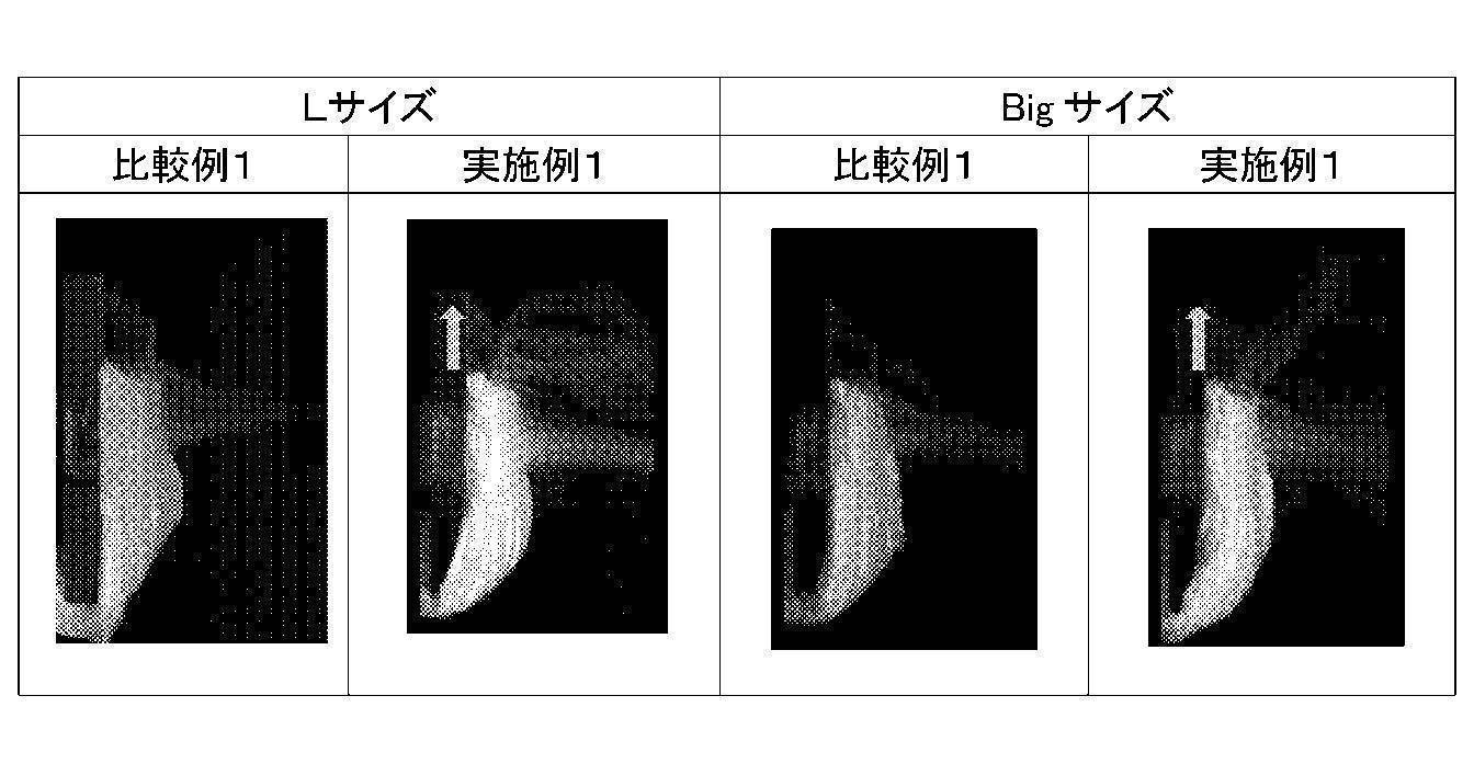
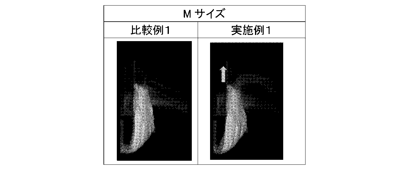
〔ウエストギャザー拡大写真〕
図10Aは、実施例に係るウエストギャザーを形成する襞の拡大写真である。図10Bは、比較例に係るウエストギャザーを形成する襞の拡大写真である。実施例及び比較例を対比すると、ウエストギャザーを形成する襞の大きさが比較例に比べて実施例の方が大きいことが判る。つまり、比較例に比べて実施例の方が、ウエストギャザーの通気性が優れていると言える。
図10Aは、実施例に係るウエストギャザーを形成する襞の拡大写真である。図10Bは、比較例に係るウエストギャザーを形成する襞の拡大写真である。実施例及び比較例を対比すると、ウエストギャザーを形成する襞の大きさが比較例に比べて実施例の方が大きいことが判る。つまり、比較例に比べて実施例の方が、ウエストギャザーの通気性が優れていると言える。
次に、本実施形態に係るおむつについて更に説明する。本実施形態に係るおむつ1において、第1収縮部S1は、胴開口端縁4F9,4R9に近接するウエスト第1領域RW1に設けられると共に胴回り方向に沿って延設される第1糸ゴム4F1,4R1を含み、胴開口部を胴回り方向に収縮させる。第2収縮部S2は、第1収縮部S1に対して股下領域1B側に隣接するウエスト第2領域RW2に設けられると共に胴回り方向に沿って延設される第2糸ゴム4F2,4F2を含み、胴開口部を胴回り方向に収縮させる。また、本実施形態におけるおむつ1においては、ウエストギャザーG2を形成する第1収縮部S1が前身頃領域1Fと後身頃領域1Rを結ぶ長手方向に延在する、胴開口部2Tからの延在長さが26mm以上31mm以下に設定するようにした。これによれば、胴開口部2Tを広げる際に、指の第2関節付近がちょうど胴開口端縁4F9、4R9に引っ掛かるため、おむつ1を着用者に装着させたり、逆に脱がせたりする際に胴開口部2Tを広げ易くなるという利点がある。より詳しくは、胴開口部2Tを広げる際に、指の第1関節よりも指先側の部位が胴開口端縁4F9、4R9に位置している場合、胴開口部2Tを広げる最中に胴開口端縁4F9、4R9から指先が不意に外れてしまい易くなる。一方、胴開口部2Tを広げる際に、第2関節よりも深い指の付け根側の部位が胴開口端縁4F9、4R9に位置している場合、第1収縮部S1よりも下方に位置する第2収縮部S2の方が広がってしまい、効率良く胴開口部2Tを広げることが難しくなり易い。これに対して、おむつ1の長手方向に沿った第1収縮部S1の延在長さを26mm以上31mm以下に設定することで、おむつ1の着脱容易性を向上させることができる。また、第1収縮部S1は、第2収縮部S2よりも横方向に伸ばすのに要する力(拡幅強度)が小さい。これにより、おむつ1の着脱容易性をより向上させることができる。また、おむつ1を広げる際に、おむつ1のウエストギャザーG2の肌当接面を形成する通気路形成シート11F,11Rに指の先端が食い込むことがなく、通気路形成シート11F,11Rが破損することを抑制できるという利点もある。
また、本実施形態におけるおむつ1において、第1収縮部S1は、シート部材が少なくとも3層に積層された積層構造を有している。これによれば、おむつ1を赤ちゃん(着用者)に履かせる際に、第1収縮部S1に配置された糸ゴム4F2,4R2同士の間に取扱者の指が入り込んだ場合においても、第1収縮部S1を形成するカバーシート4F,4Rに破れが発生することを抑制できる。
また、本実施形態におけるおむつ1においては、ウエストギャザー3Rを形成する第2収縮部S2における糸ゴム4F3,4R3は、所定の間隔(以下、「間隔A2」という)を空けて4本平行に設けられている。間隔A2を、第1収縮部S1における糸ゴム4F2,4R2の間隔A1よりも小さな寸法に設定したので、おむつ1のずれ落ちを抑制するずれ落ち抑制機能を第2収縮部S2に好適に発揮させることができる。つまり、ウエストギャザー3R全体としては、おむつ1の内部空間の湿気を外部に排出する湿気排出機能を発揮しつつ、おむつ1のずれ落ちも好適に抑制することができる。
また、本実施形態に係るおむつ1において、第2収縮部S2がおむつ長手方向(胴回り方向と直交する方向)に延在する幅寸法は20mm以上とすることが好ましい。第2収縮部S2の延在幅を上記のように設定することで、取扱者が着用者におむつ1を装着する際、着用者の肌に第2収縮部S2が食い込んでしまうことを抑制し易くなる。また、本実施形態のおむつ1において、第2収縮部S2のおむつ長手方向への延在幅は40mm以下とすることが好ましい。例えば、第1収縮部S1が長手方向に延在する胴開口端縁4F9,4R9からの範囲が31mmである場合には、第2収縮部S2が長手方向に延在する胴開口端縁4F9,4R9からの範囲が31mm以上71mm以下である。また、第1収縮部S1が長手方向に延在する胴開口端縁4F9,4R9からの範囲が26mmである場合には、第2収縮部S2が長手方向に延在する胴開口端縁4F9,4R9からの範囲が26mm以上66mm以下である。すなわち、第2収縮部S2がおむつ長手方向に延在する幅寸法は20mm以上40mm以下であり、第2収縮部S2が長手方向に延在する胴開口端縁4F9,4R9からの範囲が26mm以上71mm以下である。この場合、第1収縮部S1と第2収縮部S2は隣接していてもよい。これにより、おむつ1は、第2収縮部S2を着用者(例えば、赤ちゃん)の骨盤に当接する骨盤当接位置に対応させ、糸ゴム4F3を着用者の骨盤の左右両端部が位置する部位の付近に位置させて、第2収縮部S2を着用者の腰に保持させることができる。
<実験>
以下、本実施形態のおむつ1の一例に相当するおむつと、上記と同様に比較例のおむつ101に相当するおむつとを用意し、おむつのずれ落ち抑制機能について評価した。実施形態2のおむつ1の一例に相当する試作品のおむつを、以下、「実施例」という。また、上記比較例のおむつ101に相当する比較品のおむつを、以下、「比較例」という。
以下、本実施形態のおむつ1の一例に相当するおむつと、上記と同様に比較例のおむつ101に相当するおむつとを用意し、おむつのずれ落ち抑制機能について評価した。実施形態2のおむつ1の一例に相当する試作品のおむつを、以下、「実施例」という。また、上記比較例のおむつ101に相当する比較品のおむつを、以下、「比較例」という。
本実験では、実施例と比較例の何れについても、糸ゴム4F2,4R2に相当する糸ゴムとして「ロイカHS 470dtex」が用いられ、糸ゴム4F3,4R3、4F4,4R4に相当する糸ゴムとして「ロイカCR 470dtex」が用いられている。実施例において、糸ゴム4F2,4R2に相当する糸ゴムのドラフト率は345%であり、糸ゴム4F3,4R3に相当する糸ゴムのドラフト率は315%であり、糸ゴム4F4,4R4に相当する糸ゴムのドラフト率は330%である。比較例において、糸ゴム4F2,4R2に相当する糸ゴムのドラフト率は345%であり、糸ゴム4F3,4R3に相当する糸ゴムのドラフト率は285%であり、糸ゴム4F4,4R4に相当する糸ゴムのドラフト率は285%である。
<実験1>
実験1では、乳幼児5名の被験者A~Eに実施例と比較例のおむつを着用させて2時間自由に遊ばせて、おむつのずり落ちについて確認した。以下に示す表5は、実験1の結果を示してる。なお、表5における「お腹まわり(cm)」の欄には、各被験者のお腹まわりの大きさを記載している。

実験1では、乳幼児5名の被験者A~Eに実施例と比較例のおむつを着用させて2時間自由に遊ばせて、おむつのずり落ちについて確認した。以下に示す表5は、実験1の結果を示してる。なお、表5における「お腹まわり(cm)」の欄には、各被験者のお腹まわりの大きさを記載している。
表5において、「実施例」の欄に記載の記号「〇」は、ずれ落ちがなかった結果を示している。また、「実施例」及び「比較例」の欄に記載の記号「△」は、ずれ落ちがほとんどなかった結果を示している。また、「比較例」の欄に記載の記号「×」は、ずれ落ちがあった結果を示している。表5に示すように、実施例に係るおむつは、比較例に係るおむつよりも高いずれ落ち抑制機能を有している。
<実験2>
実験2では、赤ちゃんがずりばいした際のずれ落ち抑制機能について評価した。具体的には、EVA(ethylene-vinylacetate copolymer)製のマットの上におむつを着用させた座位姿勢のダミー人形を置き、当該おむつに150ccの人工尿を吸収保持させた。ダミー人形は、重さ4kgであり、乳児のLサイズに相当する大きさである。人工尿は、蒸留水1000mLに対して、尿素20g、塩化ナトリウム8g、硫酸マグネシウム7水和物0.8g、塩化カルシウム2水和物0.3gを溶解させて調製した。
実験2では、赤ちゃんがずりばいした際のずれ落ち抑制機能について評価した。具体的には、EVA(ethylene-vinylacetate copolymer)製のマットの上におむつを着用させた座位姿勢のダミー人形を置き、当該おむつに150ccの人工尿を吸収保持させた。ダミー人形は、重さ4kgであり、乳児のLサイズに相当する大きさである。人工尿は、蒸留水1000mLに対して、尿素20g、塩化ナトリウム8g、硫酸マグネシウム7水和物0.8g、塩化カルシウム2水和物0.3gを溶解させて調製した。
ダミー人形のお腹周りのお腹と脇腹部の上端部に印をつけ、ダミー人形をEVA製のマット上で前後方向5cmに滑らせる往復動作を1分間に60回行い、お腹と脇腹部におけるおむつのずれ落ちについて確認した。
実施例に係るおむつにおいて、お腹でのずれ落ち幅は5cmであり、脇腹部でのずれ落ち幅は0cmであった。一方、比較例に係るおむつにおいて、お腹でのずれ落ち幅は20cmであり、脇腹部でのずれ落ち幅は10cmであった。このように、実施例に係るおむつは、比較例に係るおむつよりも高いずれ落ち抑制機能を有している。これにより、着用者の乳児がずりばいをした場合であっても、おむつ1はずれ落ちを抑制できる。以上の通り、本実施形態に係るおむつ1は、着脱容易であり、ずれ落ちを抑制できる。このため、本実施形態に係るおむつ1は、二足歩行前の赤ちゃん用に好適である。
<実施形態2>
次に、実施形態2に係るおむつについて説明する。本実施形態に係るおむつ1は、上述した実施形態1に係るおむつと同一の構成要素を有する。なお、本実施形態において、上述した実施形態1と同一の構成については、同一の符号を付し、その詳細な説明を省略する。
次に、実施形態2に係るおむつについて説明する。本実施形態に係るおむつ1は、上述した実施形態1に係るおむつと同一の構成要素を有する。なお、本実施形態において、上述した実施形態1と同一の構成については、同一の符号を付し、その詳細な説明を省略する。
図11は、実施形態2に係るおむつ1を展開し、伸長した状態を模式的に示した図である。図11の(A)は、展開及び伸長した状態のおむつ1を左側から見た場合の内部構造を模式的に示している。図11の(B)は、展開及び伸長した状態のおむつ1の平面図を模式的に示している。
本実施形態に係るおむつ1では、吸収体8の長手方向端部と第1収縮部S1とは、接している。言い換えると、吸収体8の長手方向端部が第1収縮部S1端部まで延在している。これにより、第1収縮部S1の収縮により形成される第1通気路111及び第2通気路112を通じて液体を吸収した吸収体8からの湿気を外部に効率的に排出することができる。
また、本実施形態に係るおむつ1において、第1収縮部S1は、胴開口端縁4F9,4R9に近接するウエスト第1領域RW1に設けられると共に胴回り方向に沿って延設される第1糸ゴム4F1,4R1を含み、胴開口部を胴回り方向に収縮させる。第2収縮部S2は、第1収縮部S1に対して股下領域1B側に隣接するウエスト第2領域RW2に設けられると共に胴回り方向に沿って延設される第2糸ゴム4F2,4R2を含み、胴開口部を胴回り方向に収縮させる。本実施形態に係るおむつ1を平面視した場合に、吸収体8の長手方向端部は、第2収縮部S2と重なっている。第2収縮部S2は、おむつ1の長手方向に延在する範囲が15mmであり、第2糸ゴム4F2,4R2の間隔A2が5mm以上7mm以下である。なお、第2収縮部S2において、吸収体8と第2糸ゴム4F2,4R2とは、その間にシート部材(例えば、バックシート7)が配置されていてもよいし、接していてもよい。
〔実験例〕
本実施形態においても、上記実施形態1における通気性定量実験と同じ実験を行った。
表3に通気性定量試験の結果を示す。表3において、「測定位置」の列は上記実施形態1と同様の測定位置A~E(図8参照)を示し、測定位置A~Eの行は各測定位置での風速(m/s)を示す。また、本実験例では、比較例1及び実施例4ともに、Mサイズ、Lサイズ、Bigサイズの3つのサイズのおむつを作成した。

本実施形態においても、上記実施形態1における通気性定量実験と同じ実験を行った。
表3に通気性定量試験の結果を示す。表3において、「測定位置」の列は上記実施形態1と同様の測定位置A~E(図8参照)を示し、測定位置A~Eの行は各測定位置での風速(m/s)を示す。また、本実験例では、比較例1及び実施例4ともに、Mサイズ、Lサイズ、Bigサイズの3つのサイズのおむつを作成した。
表6に示すように、測定位置Aにおいては、比較例1(0.02m/s)よりも実施例4(0.24m/s)の方が、顕著に風速が増加する結果が得られた。一方、測定位置B~Eについては、実施例4と比較例1との間に有意差は認められなかった。測定位置Aについては、ウエストギャザーG2とダミー人形の肌の隙間から外部に漏れ出た空気の流れが支配的となると考えられる。そのため、測定位置Aにおける風速が比較例1に比べて顕著に増加した実施例4は、比較例に比べてウエストギャザーG2の通気性が大幅に向上していると言える。
また、第2収縮部S2を形成するシート部材を、第1収縮部S1を形成するシート部材よりも多くする。第1収縮部S1は、カバーシート4F,4Rと、折返し部4F5,4R5と、通気路形成シート11F,11Rとの合計3枚のシート部材で形成されている。第2収縮部S2は、カバーシート4F,4Rと、インナーカバーシート5F,5Rと、パッドカバーシート6と、バックシート7と、センターシート9と、折返し部4F5,4R5と、通気路形成シート11F,11Rとの合計7枚のシート部材で形成されている。さらに、第2収縮部S2は吸収体8を含んでいる。このため、第2収縮部S2は、第1収縮部S1よりも剛軟性が大きい。
おむつ1の内部空間の湿気を外部に排出する湿気排出機能や、胴開口部2Tを広げやすくする機能を第1収縮部S1が担保している。一方、ウエストギャザーG2の第2収縮部S2は、第1収縮部S1に比べて胴回り方向への収縮力を高めることで、おむつ1の着用時におけるずれ落ちを抑制する位置保持機能(ずれ落ち抑制機能)を担保するようにしている。また、第2収縮部S2を第1収縮部S1よりも剛性を大きくすることで、図4に示すカバーシート4F,4Rの第1襞41及び第2襞42、通気路形成シート11F,11Rの第1襞113及び第2襞114を大きくすることができ、以て、第1通気路111及び第2通気路112を大きくすることができる。
<実験>
以下、実施形態2のおむつ1の一例に相当するおむつと、上記実施形態1における比較例のおむつ101に相当するおむつとを用意し、おむつのずれ落ち抑制機能について評価した。実施形態2のおむつ1の一例に相当する試作品のおむつを、以下、「実施例4」という。また、上記比較例のおむつ101に相当する比較品のおむつを、以下、「比較例1」という。なお、実施例4及び比較例1においても乳児用のおむつを作成した。
以下、実施形態2のおむつ1の一例に相当するおむつと、上記実施形態1における比較例のおむつ101に相当するおむつとを用意し、おむつのずれ落ち抑制機能について評価した。実施形態2のおむつ1の一例に相当する試作品のおむつを、以下、「実施例4」という。また、上記比較例のおむつ101に相当する比較品のおむつを、以下、「比較例1」という。なお、実施例4及び比較例1においても乳児用のおむつを作成した。
本実験では、実施例4と比較例1の何れについても、第1糸ゴム4F1,4R1に相当する糸ゴムとして「ロイカHS 470dtex」が用いられ、第2糸ゴム4F2,4R2、第3糸ゴム4F3,4R3に相当する糸ゴムとして「ロイカCR 470dtex」が用いられている。実施例4において、第1糸ゴム4F1,4R1に相当する糸ゴムのドラフト率はMサイズで330%でありLサイズで345%である。一方、比較例1において、第1糸ゴム4F1,4R1に相当する糸ゴムのドラフト率はサイズに関わりなく315%である。また、実施例4及び比較例1ともに、第2糸ゴム4F2,4R2に相当する糸ゴムのドラフト率はサイズに関わりなく315%である。また、実施例4及び比較例1ともに、第3糸ゴム4F3,4R3に相当する糸ゴムのドラフト率はサイズに関わりなく330%である。
表7に比較例1及び実施例4における第1収縮部での糸ゴム及び第2収縮部内での吸収体8と第1収縮部との距離についてまとめて示す。

また、実施例4及び比較例1において、第1収縮部S1及び第2収縮部S2に相当する部位の剛性を測定した。この測定は、JISL1069に準ずるカンチレバーによる剛軟度測定により行った。実施例4において、第1収縮部S1に相当する部位の剛軟性は61mmNであり、第2収縮部S2に相当する部位の剛軟性は、112mmNであった。剛軟性は数値が小さいほど曲がりやすい状態を示しており、実施例4の第2収縮部は第1収縮部よりも曲がりにくく、襞が大きくなる。皺の数については、第2糸ゴム4F2,4R2の中央付近を伸長状態にして幅5cmをカットし、収縮した状態で襞の本数と平均襞高さを測定した。比較例1では9本(平均襞高さ1.3mm)であったのに対し、実施例4では本数が6本(平均襞高さ2mm)であった。通気性の指標である襞の断面積を比較すると、比較例1では16.25mm2に対し、実施例4では25mm2となり、実施例4は比較例1よりも断面積が約1.5倍向上する。
また、実施例4及び比較例1において、第1収縮部S1及び第2収縮部S2に相当する部位の拡幅強度を測定した。
〔拡幅強度試験〕
実施例4及び比較例1に対する拡幅強度試験について説明する。ここでは、実施例4及び比較例1の各々について、胴開口部が拡幅変形する際のウエストギャザーにおける第1収縮部と第2収縮部を合わせた範囲での拡幅強度について測定した。なお、拡幅強度試験は、実施例4及び比較例1について、それぞれBigサイズ、Lサイズ、Mサイズの3種類に対して実施した。実施例4・比較例1ともにMサイズの第2収縮部S2については間隔7mm、5本、Lサイズ及びBigサイズの第2糸ゴムについては、間隔5mm、4本とした。
実施例4及び比較例1に対する拡幅強度試験について説明する。ここでは、実施例4及び比較例1の各々について、胴開口部が拡幅変形する際のウエストギャザーにおける第1収縮部と第2収縮部を合わせた範囲での拡幅強度について測定した。なお、拡幅強度試験は、実施例4及び比較例1について、それぞれBigサイズ、Lサイズ、Mサイズの3種類に対して実施した。実施例4・比較例1ともにMサイズの第2収縮部S2については間隔7mm、5本、Lサイズ及びBigサイズの第2糸ゴムについては、間隔5mm、4本とした。
上記のように作製したリング状の試験片を、ストログラフ引張試験機(東洋精機社製、品番:YG1E)の上チャック部と下チャック部にそれぞれ固定した治具に引っ掛けることでセットし、上下のチャック部同士の離間距離を徐々に広げることで試験片が拡幅変形する際の反力をロードセルで測定することで、実施例4及び比較例1における第2収縮部の拡幅強度(胴回り方向の収縮力)を取得した。ここで、上下のチャック部間距離を広げる際の速度は、200mm/分とした。なお、Mサイズの試験片の拡幅強度は、上下のチャック部同士の離間距離が30cm、44cm、58cmのときに測定した測定結果の平均値として算出した。また、Lサイズ及びBigサイズの試験片の拡幅強度は、上下のチャック部同士の離間距離が38cm、48cm、62cmのときに測定した測定結果の平均値として算出した。
表8に、実施例4及び比較例1に対する拡幅強度試験の結果を示す。

表8に示すように、比較例1で作成した各試験片の拡幅幅44cmでの拡幅強度の平均値はMサイズおよびBigサイズで2.6N、Lサイズ2.8Nに対し、実施例4で作成した各試験片の拡幅幅44cmでの拡幅強度の平均値はMサイズおよびBigサイズで2.4N、Lサイズ2.5Nであった。ウエストギャザーにおける第2収縮部に、着用者からおむつがずれ落ちることを抑制するずれ落ち抑制機能を担保させる観点からは、第2収縮部の拡幅強度はMサイズおよびBigサイズでは1.4N以上3.4N以下、Lサイズでは1.5N以上3.5N以下であることが好ましく、実施例4の拡幅強度は上記適性範囲に含まれていることからも、実施例はおむつのずれ落ち抑制機能を十分に発揮なし得ることが確認された。
<実施形態3>
次に、実施形態3に係るおむつについて説明する。本実施形態に係るおむつ1は、上述した実施形態1に係るおむつと同一の構成要素を有する。なお、本実施形態において、上述した実施形態1と同一の構成については、同一の符号を付し、その詳細な説明を省略する。
次に、実施形態3に係るおむつについて説明する。本実施形態に係るおむつ1は、上述した実施形態1に係るおむつと同一の構成要素を有する。なお、本実施形態において、上述した実施形態1と同一の構成については、同一の符号を付し、その詳細な説明を省略する。
本実施形態に係るおむつ1は、着用時において、吸収体8の長手方向端部付近と重なる領域のセンターシート9(「肌側シート部材」の一例)と着用者の肌との間に空間が形成されることに特徴を有している。なお、センターシート9は、吸収体8に積層されて肌対向面を形成するシート部材である。
次に上記空間する構成例について図12を用いて説明する。図12は、実施形態3に係るおむつ1を展開し、伸長した状態を模式的に示した図である。図12の(A)は、展開及び伸長した状態のおむつ1を左側から見た場合の内部構造を模式的に示している。図12の(B)は、展開及び伸長した状態のおむつ1の平面図を模式的に示している。
本実施形態に係るおむつ1は、平面視した場合に吸収体8の長手方向端部付近と重なる領域に当該端部方向に向かって凸状となる折り曲げ線50F,50Rが形成されている。折り曲げ線50F,50Rは、吸収体8に形成されていてもよいし、センターシート9に形成されていてもよい。折り曲げ線50F,50Rは、吸収体8又はセンターシート9に形成された圧搾溝であってもよい。また、折り曲げ線50F,50Rは、センターシート9を2枚のシート部材で形成し、当該2枚のシート部材の接着部位で形成するエンボス加工(3Dエンボス)により形成してもよい。
おむつ1は、折り曲げ線50F,50Rによって吸収体8の長手方向端部が着用時にいて湾曲するようにし、センターシート9と着用者の肌との間に空間を形成することができる。おむつ1は、液体を吸収した吸収体8からの湿気を当該空間を介して第1通気路111及び第2通気路112に流し、湿気を外部に効率的に排出することができる。このように、本実施形態に係るおむつ1は、通気性が良好である。
なお、おむつ1において上記の空間は、吸収体8の長手方向端部に伸張状態の糸ゴムを接着させることにより形成されるようにしてもよい。
<実施形態4>
次に、実施形態4に係るおむつについて説明する。
次に、実施形態4に係るおむつについて説明する。
吸収性物品の着用時においては、吸収体に吸収された尿や体液等から発生する湿気が吸収性物品の内部空間(着用者の肌と吸収性物品の肌当接面との間に形成される空間)に滞留しやすく、この湿気は肌かぶれ等のスキントラブルを引き起こす要因となり、また、蒸れ・べたつき等の不快感を生じさせる要因となるため、好ましくない。
そこで、吸収性物品の着用時に、吸収性物品の内部空間に滞留する湿気を外部に排出させるために、吸収性物品の通気性を向上させるための種々の提案がなされている(例えば、特許第5573806号公報等を参照)。例えば、弾性部材により外層シート及び内層シートをウエスト周方向に収縮させてウエスト回りに襞を形成し、襞と着用者の肌との隙間から湿気を外部に排出させるようにした使い捨ておむつが知られている。
上記のように、吸収性物品の通気性を向上させるための各種提案はなされているが、より通気性の高い吸収性物品の提供が望まれているのが実情である。そこで、本実施形態は、従来に比べて通気性が良好な吸収性物品を提供することを目的の一つとする。
上記課題を解決するため、本実施形態に係る吸収性物品は、着用者の腹部を覆う前身頃領域と、着用者の背部を覆う後身頃領域と、前身頃領域及び後身頃領域の間に位置すると共に吸収体が配置される股下領域が連設された吸収性物品であって、前身頃領域及び後身頃領域のうち、着用者の胴部を挿通可能な胴開口部において、少なくとも着用者の腰骨に対応する部位から胴回り方向に沿って延設される複数の伸縮部材を含み、胴開口部を胴回り方向に収縮させる胴開口部下側収縮部と、胴開口部の開口部端縁と胴開口部下側収縮部との間において胴回り方向に沿って延設される複数の伸縮部材を含み、胴開口部を胴回り方向に収縮させる胴開口部上側収縮部と、を備え、胴開口部下側収縮部が有する複数の伸縮部材同士の間隔は、胴開口部上側収縮部が有する複数の伸縮部材同士の間隔よりも大きい。
なお、胴開口部下側収縮部が有する複数の伸縮部材同士の間隔は、6.5mm以上12mm以下であってもよい。
また、胴開口部下側収縮部は、開口部端縁から20mm以上40mm以下の範囲内を含む領域に設けられていてもよい。
また、胴開口部上側収縮部と胴開口部下側収縮部における肌対向面を覆うように積層配置される通気路形成シートを更に備え、通気路形成シートは、肌対向面に対して胴回り方向に沿って間欠的に複数設けられる接合部によって接合されており、胴開口部上側収縮部と胴開口部下側収縮部の収縮によって接合部同士の間に位置する非接合領域が撓み、波型に変形することで通気路を形成してもよい。
また、開口部端縁と胴開口部上側収縮部との間において開口部端縁に沿って胴回り方向に延設される複数の伸縮部材を含み、胴開口部を胴回り方向に収縮させる開口部端縁側収縮部を更に備え、開口部端縁側収縮部が有する複数の伸縮部材同士の間隔は、胴開口部上側収縮部が有する複数の伸縮部材同士の間隔よりも大きくてもよい。
また、胴開口部上側収縮部が有する伸縮部材を、胴開口部を形成する部分に内包したカバーシートを備え、カバーシートは、開口部端縁の部分で折り返されており、折り返し部分の折り目にカバーシートを貫通する連続的な通気孔を有していてもよい。
本実施形態に係る吸収性物品であれば、従来に比べて良好な通気性を得ることが可能となる。
以下、本発明の実施形態4について説明する。以下に示す実施形態は、本発明の実施形態の一例であり、本発明の技術的範囲を以下の態様に限定するものではない。
図13は、実施形態4に係るパンツ型使い捨ておむつ(以下、単に「おむつ」という)1の斜視図である。図14は、実施形態4に係るおむつ1の分解斜視図である。また、図15は、実施形態に係るおむつ1を展開した状態を模式的に示した図である。図15の(A)は、展開時におけるおむつ1を左側から見た場合の内部構造を模式的に示している。図15の(B)は、展開時におけるおむつ1の平面構造を模式的に示している。
本明細書で用いる方向に関する用語は、おむつ1が着用者に着用された状態において該着用者の前後左右に一致する方向を意味するものとする。例えば、本明細書で左右方向という場合、おむつ1の着用者に着用された状態において該着用者の左右に一致する方向を意味する。
また、本明細書において、おむつ1の「前身頃領域」とは、着用者におむつ1を装着した際に、着用者の腹部(身体前方)を覆う部分を意味する。おむつ1の「股下領域」とは、着用者におむつ1を装着した際に、着用者の股下を覆う部分を意味する。おむつ1の「後身頃領域」とは、着用者におむつ1を装着した際に、着用者の背部(身体後方)を覆う部分を意味する。また、本明細書において、「長手方向」とは、おむつ1の前身頃領域と後身頃領域を結ぶ方向を意味する。すなわち、おむつ1の長手方向は、前身頃領域、股下領域、及び後身頃領域が連設される連設方向に一致している。また、「幅方向」とは、おむつ1の長手方向に直交する方向を意味する。
本実施形態では、吸収性物品の一例として、着用者の腹囲が入る開口部と、着用者の左下肢及び右下肢が挿通される左右一対の開口部とを有する筒状構造のパンツ型使い捨ておむつを例示するが、本明細書における「吸収性物品」は、パンツ型使い捨ておむつに限定されるものでない。「吸収性物品」には、例えば、着用者の股下(陰部)を前身頃領域から後身頃領域にかけて覆うシート状の部材の一端部付近に固定されたテープを、該シート状の部材の他端部付近に貼り付けることで筒状構造を形成するテープ型使い捨ておむつ等、腹囲と股下を包み得る各種形態の吸収性物品が含まれる。
図13~15に示すように、おむつ1は、着用状態において着用者の股下(陰部)を覆う股下領域1Bと、着用者の腹部を覆う前身頃領域1Fと、着用者の背部を覆う後身頃領域1Rとを有している。股下領域1Bは、前身頃領域1Fと後身頃領域1Rの間に位置すると共に前身頃領域1Fと後身頃領域1Rに連設されており、股下領域1Bには液体を吸収して保持する吸収部本体15(吸収体8)が設けられている。
本実施形態におけるおむつ1は、パンツ型の使い捨ておむつであるため、前身頃領域1Fの左側縁と後身頃領域1Rの左側縁が互いに接合され、前身頃領域1Fの右側縁と後身頃領域1Rの右側縁が互いに接合されることで、図13に示す状態に組み上がる。図13に示されるように、前身頃領域1Fの上端縁と後身頃領域1Rの上端縁により、胴開口部(ウエスト開口部)2Tが形成されている。また、おむつ1には、上記接合が施されない股下領域1Bの左側部に左下肢開口部2Lが形成され、股下領域1Bの右側部に右下肢開口部2Rが形成されている。左下肢開口部2L及び右下肢開口部2Rは、おむつ1の装着時に着用者の脚部を挿通させるための開口部である。
着用者の左下肢が左下肢開口部2Lに挿通され、着用者の右下肢が右下肢開口部2Rに挿通され、着用者の胴部が胴開口部2Tに入る(通る)ようにおむつ1が装着されると、前身頃領域1Fが着用者の腹部に接すると共に後身頃領域1Rが着用者の背部側に接し、股下領域1Bが着用者の股部にあてがわれ、更に、左下肢開口部2Lと右下肢開口部2Rが着用者の大腿部を取り巻いた状態で着用者の身体に固定される。おむつ1がこのようにして着用者の身体に固定されることで、おむつ1を着用した状態での立ち歩きが可能となる。
おむつ1には、液体を吸収して保持することができる吸収体8が主に股下領域1B付近を中心に配置されている。また、おむつ1には、おむつ1と着用者の肌との間に液体の流出経路となる隙間が形成されるのを抑制するために、左下肢開口部2L、右下肢開口部2R、胴開口部2Tにそれぞれ、立体ギャザーG1L、立体ギャザーG1R、ウエストギャザーG2が設けられている。立体ギャザーG1L,G1RとウエストギャザーG2は、糸ゴムの弾性力で着用者の肌に密着するように構成されており、これによって、着用者から排出された排泄液をおむつ1から漏出させることなく吸収部本体15(吸収体8)に吸収させることができる。
図14及び図15に示すように、おむつ1は、着用者に装着された状態において外表面を形成するカバーシート4F,4Rとパッドカバーシート6を有する。カバーシート4Fは、主におむつ1の前身頃領域1Fの外表面を形成するシート部材である。また、パッドカバーシート6は、主におむつ1の股下領域1Bの外表面を形成するためのシート部材である。また、カバーシート4Rは、主におむつ1の後身頃領域1Rの外表面を形成するためのシート部材である。
カバーシート4F,4Rとパッドカバーシート6は、例えば、おむつ1の外表面の補強や手触りの向上のために設けられている。また、カバーシート4F,4Rとパッドカバーシート6は、排泄物の漏れを抑制するために、例えば液不透過性の熱可塑性樹脂からなる不織布によって形成することができる。ここで、液不透過性の熱可塑性樹脂としては、ポリエチレン(PE)やポリプロピレン(PP)等が例示できる。また、液不透過性のシートには、液不透過性と透湿性とが発揮されるように、0.1~数μm程度の微細な孔が多数形成されていても良い。
また、おむつ1は、カバーシート4Fの肌対向面側に積層されるインナーカバーシート5Fと、カバーシート4Rの肌対向面側に積層されるインナーカバーシート5Rとを有している。本明細書において、「肌対向面」とは、おむつ1を着用者が着用した際に、着用者の肌に対向する方の面を意味する。詳しくは後述するが、インナーカバーシート5Fは、カバーシート4Fとの層間に線状の伸縮部材である糸ゴムを挟み込んだ状態でカバーシート4Fに貼り合わされるシート部材である。インナーカバーシート5Fは、カバーシート4Fのうち、後述する折返し部4F5と、外装カバー部4F10におけるウエスト第1領域RW1を除いた部分に対応する形状及び大きさを有するシート部材である。また、インナーカバーシート5Rは、カバーシート4Rとの層間に線状の伸縮部材である糸ゴムを挟み込んだ状態でカバーシート4Fに貼り合わされるシート部材である。インナーカバーシート5Rは、カバーシート4Rのうち、後述する折返し部4R5と、外装カバー部4R10におけるウエスト第1領域RW1を除いた部分に対応する形状及び大きさを有するシート部材である。
本実施形態のおむつ1は、吸収部本体15を備えている。吸収部本体15は、前身頃領域1Fと後身頃領域1Rとの間に架橋された状態で保持され、おむつ1の着用時に着用者の股下に配置され、着用者が排泄した尿などの液体を吸収保持する。図14及び図15に示すように、吸収部本体15は、パッドカバーシート6、バックシート7、吸収体8、センターシート9、サイドシート10L,10R等を含み、これらによって一体に形成されている。
バックシート7、吸収体8、センターシート9は、パッドカバーシート6の肌対向面に対して順に積層されている。パッドカバーシート6は、着用者の前身頃から股下を経由して後身頃へ届く長さを長手方向に有しており、当該長手方向に対し直交する幅方向に所定の横幅を有する矩形平面を有するシート部材である。また、バックシート7、吸収体8、センターシート9は、何れもパッドカバーシート6と同様に矩形平面を有するシート部材であり、長手方向がパッドカバーシート6の長手方向と一致する状態でパッドカバーシート6に対してこれらの順に積層されている。
吸収体8は、尿などの液体を吸収し、吸収した液体を保持するための部材である。吸収体8は、液不透過性のバックシート7と液透過性のセンターシート9との間に配置される。吸収体8は、パルプ繊維、レーヨン繊維、またはコットン繊維のようなセルロース系繊維の短繊維や、ポリエチレン、ポリプロピレン、またはポリエチレンテレフタレート等の合成繊維に親水化処理を施した短繊維の隙間に、水を吸収し保持することのできる架橋構造を持つ親水性の高吸収性重合体等の粒状の吸収性樹脂を保持させた構造を有していても良い。これにより、吸収体8は、着用者から排泄された液体を吸収すると、短繊維内の隙間に保持された吸収性樹脂を膨潤させて該液体を短繊維内に保持することができる。なお、吸収体8は、1枚のマットからなる単層構造であってもよいし、複数枚のマットを重ね合わせた積層構造であってもよい。また、吸収体8は、目的に応じた適宜の形状を採用することができる。吸収体8の形状としては、例えば、矩形状、中央部付近が括れた砂時計型、その他各種の形状が挙げられる。
センターシート9は、着用者の股下の肌に直接当たり、尿などの液体を吸収体8へ透過させるためのシート部材であり、吸収体8の吸水面を被覆するように積層配置されている。本実施形態におけるセンターシート9は、柔軟性の高い液透過性材料によって形成されている。センターシート9を形成する液透過性材料としては、例えば、織布、不織布、多孔質フィルム等が例示できる。また、センターシート9は親水性を有していてもよい。
バックシート7は、センターシート9を透過し吸収体8に吸収された液体が、おむつ1の外側へ漏出することを抑制するためのシート部材である。このため、バックシート7は、液不透過性材料によって形成されている。バックシート7を形成する液不透過性材料としては、ポリエチレン樹脂からなる液不透過性のフィルムなどを例示できる。また、バックシート7は、通気性を確保するために、多数の微細孔が形成された微多孔性ポリエチレンフィルムによって形成されても良い。
パッドカバーシート6は、バックシート7を補強し、かつ、その肌触りを良くするための部材であり、バックシート7に貼り合されている。パッドカバーシート6を形成する材料としては、織布や不織布が例示できる。また、パッドカバーシート6は、ポリエチレン、ポリプロピレン、ポリエステルのような熱可塑性樹脂からなる不織布又は湿式不織布等であっても良い。
吸収部本体15におけるサイドシート10L,10Rは、上述した立体ギャザーG1L,G1Rを形成するための細長い帯状部材である。サイドシート10L,10Rは、センターシート9の長辺部分に沿って延設されている。また、サイドシート10L,10Rには、長手方向に沿って糸ゴム10L1,10R1が接着されている。前身頃領域1Fの左側縁を形成するカバーシート4Fの左側縁4F7と後身頃領域1Rの左側縁を形成するカバーシート4Rの左側縁4R7が互いに接合され、且つ、前身頃領域1Fの右側縁を形成するカバーシート4Fの右側縁4F8と後身頃領域1Rの右側縁を形成するカバーシート4Rの右側縁4R8が互いに接合されることで図13に示すおむつ1が組み上がると、サイドシート10L,10Rが糸ゴム10L1,10R1の収縮力によって長手方向に引き寄せられる結果、折り返し線10L2,10R2に沿ってセンターシート9から立ち上がる。
これにより、左下肢開口部2L及び右下肢開口部2Rからの液体の流出を防ぐ立体ギャザーG1L,G1Rが形成される。カバーシート4F,4Rの側縁同士の接合方法は特に限定されないが、例えば、ヒートシール、高周波シール、超音波シール等が例示できる。なお、吸収部本体15は、前身頃領域1Fから後身頃領域1Rに至るまで延在している。
次に、おむつ1の詳細構造について説明する。図15に示すように、カバーシート4Fは、折り返し線4F6を境に先端側が内側に折り返されることで、折返し部4F5が形成されている。以下、カバーシート4Fのうち、折返し部4F5を除く部分を外装カバー部4F10と呼ぶ。カバーシート4Fの外装カバー部4F10は、おむつ1の外表面を形成する。カバーシート4Fの折り返し線4F6は、おむつ1が組み上がった状態における胴開口部2Tの胴開口端縁4F9を形成する。
カバーシート4Fにおける折返し部4F5は、外装カバー部4F10との層間に伸長状態の第1糸ゴム4F1を配置している。また、カバーシート4Fにおける折返し部4F5の先端側は、インナーカバーシート5F、パッドカバーシート6、バックシート7、及び吸収体8の長手方向における一端側を外装カバー部4F10との層間に挟み込んだ状態で、吸収体8の一端部に重ねられた状態で接着されている。なお、本明細書において、一の部材と他の部材とを重ねると表現する際の態様には、部材同士が互いに全面的に接触する状態で重なる態様に限定されるものでなく、一の部材の一部と他の部材の全体が重なる態様、或いは、一の部材と他の部材の一部同士が重なる態様等を含む概念である。
更に、図15に示すように、カバーシート4Fにおける外装カバー部4F10とインナーカバーシート5Fとの層間には、折り返し線4F6側から第2糸ゴム4F2、第3糸ゴム4F3、第4糸ゴム4F4が、これらの順に配置されており、外装カバー部4F10とインナーカバーシート5Fに挟み込まれた状態で接着されている。図15に示すように、カバーシート4Fにおける第1糸ゴム4F1~第4糸ゴム4F4は、各々が複数本ずつ平行に配置されており、いずれもカバーシート4Fの幅方向(胴回り方向)に沿って延設されている。
一方、カバーシート4Rについても、折り返し線4R6を境に先端側が内側に折り返されることで、折返し部4R5が形成されている。以下、カバーシート4Rのうち、折返し部4R5を除く部分を外装カバー部4R10と呼ぶ。カバーシート4Rの外装カバー部4R10は、おむつ1の外表面を形成する。カバーシート4Rの折り返し線4R6は、おむつ1が組み上がった状態における胴開口部2Tの胴開口端縁4R9を形成する。カバーシート4Rにおける折返し部4R5は、外装カバー部4R10との層間に伸長状態の第1糸ゴム4R1を配置している。また、カバーシート4Rにおける折返し部4R5の先端側は、インナーカバーシート5R、パッドカバーシート6、バックシート7、及び吸収体8の長手方向における他端側を外装カバー部4R10との層間に挟み込んだ状態で、吸収体8の他端部に重ねられた状態で接着されている。
更に、図15に示すように、カバーシート4Rにおける外装カバー部4R10とインナーカバーシート5Rとの層間には、折り返し線4R6側から第2糸ゴム4R2、第3糸ゴム4F3、第4糸ゴム4R4がこれらの順に配置されており、外装カバー部4R10とインナーカバーシート5Rとに挟まれた状態で接着されている。図15に示すように、カバーシート4Rにおける第1糸ゴム4R1~第4糸ゴム4R4は、各々が複数本ずつ平行に配置されており、いずれもカバーシート4Rの幅方向(胴回り方向)に沿って延設されている。
以下、おむつ1のカバーシート4F,4Rにおいて、第1糸ゴム4F1,4R1、及び第2糸ゴム4F2,4R2が配置されている領域を「ウエスト領域RW」と呼ぶ。おむつ1のウエスト領域RWは、胴開口部2Tを形成する胴開口端縁4F9,4R9近傍に位置し、ウエストギャザーG2が形成される領域である。更に、ウエスト領域RWのうち、第1糸ゴム4F1,4R1が配置されている領域を「ウエスト第1領域RW1」(第1領域)と呼び、第2糸ゴム4F2,4R2が配置されている領域を「ウエスト第2領域RW2」(第2領域)と呼ぶ。
また、おむつ1のカバーシート4F,4Rにおいて、第3糸ゴム4F3,4R3、及び第4糸ゴム4F4,4R4が配置されている領域を「タミー領域RT」と呼ぶ。タミー領域RTは、ウエスト領域RWの下方に位置する領域である。タミー領域RTのうち、第3糸ゴム4F3,4R3が配置されている領域を「タミー第1領域RT1」と呼び、第4糸ゴム4F4,4R4が配置されている領域を「タミー第2領域RT2」と呼ぶ。
ここで、ウエスト第1領域RW1における第1糸ゴム4F1,4R1は、例えばおむつ1の組み立て過程において、伸長された状態で接着剤を塗布された後、外装カバー部4F10,4R10と折返し部4F5,4R5の間に挟み込まれることでこれらの層間に接着される。同様に、ウエスト第2領域RW2における第2糸ゴム4F2,4R2と、タミー領域RTにおける第3糸ゴム4F3,4R3及び第4糸ゴム4F4,4R4は、例えばおむつ1の組み立て過程において、伸長された状態で接着剤が塗布された後、カバーシート4F,4Rの外装カバー部4F10,4R10とインナーカバーシート5F,5Rの間に挟み込まれることでこれらの層間に接着される。
ここで、カバーシート4F,4Rにおける外装カバー部4F10,4R10とインナーカバーシート5F,5Rとの層間に伸長状態で挟み込まれて接着されたウエスト第1領域RW1の第1糸ゴム4F1,4R1が収縮すると、それに追従して外装カバー部4F10,4R10と折返し部4F5,4R5のうち、ウエスト第1領域RW1に対応する部分がひだ状に連続的に撓むことで、ウエスト第1領域RW1を胴回り方向に収縮させる第1収縮部S1が形成される。
ウエスト第2領域RW2においても、外装カバー部4F10,4R10とインナーカバーシート5F,5Rとの層間に伸長状態で挟み込まれて接着された第2糸ゴム4F2,4R2が収縮すると、それに追従して外装カバー部4F10,4R10とインナーカバーシート5F,5Rのうち、ウエスト第2領域RW2に対応する部分がひだ状に連続的に撓むことで、ウエスト第2領域RW2を胴回り方向に収縮させる第2収縮部S2(本願でいう「胴開口部上側収縮部」の一例である)が形成される。
本実施形態においては、主としてウエスト第1領域RW1に形成される第1収縮部S1とウエスト第2領域RW2に形成される第2収縮部S2によってウエストギャザーG2が形成されている。ウエストギャザーG2は、第1糸ゴム4F1,4R1及び第2糸ゴム4F2,4R2の収縮力によって、着用者のウエスト回りにおけるおむつ1のフィット性を向上させる。ウエストギャザーG2の第1収縮部S1には、複数の第1糸ゴム4F1,4R1が互いに平行に、且つ一定間隔A1で配置されている。また、ウエストギャザーG2の第2収縮部S2には、複数の第2糸ゴム4F2,4R2が互いに平行且つ一定の間隔A2を空けて設けられている。なお、ここでいう糸ゴム同士の間隔とは、隣の糸ゴム同士がおむつの長手方向(身頃領域と後身頃領域を結ぶ方向)に離間する寸法を意味する。
また、本実施形態において、ウエスト第1領域RW1の第1糸ゴム4F1,4R1及びウエスト第2領域RW2の第2糸ゴム4F2,4R2は、カバーシート4F,4Rの全幅区間に亘って延在している。そのため、おむつ1の完成後において、第1糸ゴム4F1,4R1及び第2糸ゴム4F2,4R2は、胴開口部2Tに沿って周回する実質的に環状の伸縮部材を形成する。言い換えると、おむつ1の完成後において、ウエストギャザーG2(第1収縮部S1、第2収縮部S2)が胴回り方向の全周に亘って形成される。
タミー第1領域RT1においても、カバーシート4F,4Rにおける外装カバー部4F10,4R10とインナーカバーシート5F,5Rとの層間に伸長状態で挟み込まれて接着された第3糸ゴム4F3,4R3が収縮すると、それに追従してカバーシート4F,4Rにおける外装カバー部4F10,4R10とインナーカバーシート5F,5Rのうち、タミー第1領域RT1に対応する部分がひだ状に連続的に撓むことで、タミー第1領域RT1を胴回り方向に収縮させる第3収縮部S3(本願でいう「胴開口部下側収縮部」の一例である)が形成される。第3収縮部S3は、おむつ1の着用時に着用者の腰骨の高さ近傍にフィットする領域であり、胴開口部2Tの開口部端縁から20mm以上40mm以下の範囲内を含む領域に設けられている。
また、タミー第2領域RT2においても、カバーシート4F,4Rにおける外装カバー部4F10,4R10とインナーカバーシート5F,5Rとの層間に伸長状態で挟み込まれて接着された第4糸ゴム4F4,4R4が収縮すると、それに追従してカバーシート4F,4Rにおける外装カバー部4F10,4R10とインナーカバーシート5F,5Rのうち、タミー第2領域RT2に対応する部分がひだ状に連続的に撓むことで、タミー第2領域RT2を胴回り方向に収縮させる第4収縮部S4が形成される。そして、本実施形態においては、主としてタミー第1領域RT1に形成される第3収縮部S3とタミー第2領域RT2に形成される第4収縮部S4によってタミーギャザーG3が形成されている。タミーギャザーG3は、第3糸ゴム4F3,4R3及び第4糸ゴム4F4,4R4の収縮力によって、例えば着用者の下腹部回りにおけるおむつ1のフィット性を向上させている。
タミーギャザーG3の第3収縮部S3に配置される第3糸ゴム4F3,4R3は、互いに平行に、且つ一定の間隔A3を空けて設けられている。また、タミーギャザーG3の第4収縮部S4に配置される第4糸ゴム4F4,4R4も、互いに平行に、且つ一定の間隔A4を空けて設けられている。そして、本実施形態では、タミーギャザーG3の第3収縮部S3における第3糸ゴム4F3,4R3の間隔A3が、ウエストギャザーG2の第2収縮部S2における第2糸ゴム4F2,4R2の間隔A2よりも大きな寸法に設定されており、これにより、胴開口部2Tを広げておむつ1を装着する際、着用者の腰骨に当接する部位となるタミーギャザーG3の第3収縮部S3を、ウエストギャザーG2の第2収縮部S2よりも相対的に広げやすくしている。
また、本実施形態においては、第1収縮部S1~第4収縮部S4を形成するために、各糸ゴム4F1,4R1、4F2,4R2、4F3,4R3、4F4,4R4をカバーシート4F,4Rの幅方向(胴回り方向)に沿って延設したが、線状の伸縮部材であれば糸ゴムに限らず、他の材料、形態を用いても良い。また、本明細書において「線状」とは、細長く特定の方向に延びる態様を表すものであり、帯状、短冊状の形状を含む概念である。なお、糸ゴムの材料としては、天然ゴム、合成ゴム等が例示できるが、特定の材料には限定されない。
次に、おむつ1の通気路形成シート11F,11Rについて説明する。図14及び図15に示すように、おむつ1は、カバーシート4F,4Rにおける折返し部4F5,4R5と、吸収部本体15におけるパッドカバーシート6、センターシート9等の長手方向端部領域において、当該折返し部4F5,4R5に積層配置される通気路形成シート11F,11Rを備える。通気路形成シート11F,11Rは、おむつ1のウエストギャザーG2及びタミーギャザーG3における肌当接面を形成する。「肌当接面」とは、おむつ1の着用時に、着用者の肌に直接当たる面、すなわちおむつ1の最内面を意味する。
図16は、実施形態に係るおむつ1の通気路形成シート11F,11Rの設置態様について説明する図である。図16の(A)は、ウエストギャザーG2の第1収縮部S1をおむつ1の内部空間側から眺めた状態を示す図である。また、図16の(B)は、おむつ1の側方から見た場合のウエストギャザーG2の第1収縮部S1内の内部構造を模式的に示す図である。また、図16の(C)は、おむつ1の上方(すなわち、(B)のA矢視方向)からウエストギャザーG2の第1収縮部S1を眺めた状態を示す図である。図16の(A)及び(C)は、便宜上、ウエストギャザーG2における第1収縮部S1が収縮する前の状態を示している。また、図16の(D)は、収縮後におけるウエストギャザーG2の第1収縮部S1を上方から眺めた状態を示す図である。
通気路形成シート11F,11Rは、少なくとも第1収縮部S1、第2収縮部S2及び第3収縮部S3に対応する部位に配置されており、符号Sによって示される接合部を介して、パッドカバーシート6における長手方向の端部領域及び折返し部4F5,4R5等に接合されている。図17は、通気路形成シート11F,11Rを接合している接合部Sの部位を示した図である。本実施形態では、熱可塑性樹脂によって形成されたカバーシート4F,4Rの折返し部4F5,4R5及びパッドカバーシート6に重ねた通気路形成シート11F,11Rを、超音波溶着で接合することにより、接合部Sを形成している。図16(A)や図17に示されるように、カバーシート4F,4Rの胴開口端縁4F9,4R9から胴回り方向(幅方向)に直交する長手方向に沿って複数の接合部Sが間欠的に配置されることで、おむつ1の長手方向に延びる線状接合部SLが形成されている。言い換えると、1つの線状接合部SLは、おむつ1の長手方向に沿って間欠的に配置される複数の接合部Sの集合体として形成されている。ここで、「間欠的」に配置されるとは、非連続的、或いは断続的に配置される態様を意味する。
図16(A)に示すように、ウエストギャザーG2の第1収縮部S1には、複数本の線状接合部SLが、カバーシート4F,4Rの胴回り方向(幅方向)に沿って間欠的に配置されている。図16(A)に示す例では、各線状接合部SLが互いに平行に設けられており、線状接合部SL同士の間隔が大小交互となるように設定されている。つまり、1組の線状接合部SLによって形成される二重線が胴回り方向(幅方向)に等間隔で並ぶような形態で線状接合部SLが間欠的に配置されている。なお、図15(A)には、線状接合部SLがおむつ1の長手方向に延在する範囲をハッチングにて図示している。図示のように、線状接合部SLは、第1収縮部S1が形成されるウエスト第1領域RW1及び第2収縮部S2が形成されるウエスト第2領域RW2に跨って延在している。
ウエストギャザーG2の第1収縮部S1と第2収縮部S2及びタミーギャザーG3の第3収縮部S3における通気路形成シート11F,11Rの超音波接合は、ウエストギャザーG2の第1糸ゴム4F1,4R1及び第2糸ゴム4F2,4R2と、タミーギャザーG3の第3糸ゴム4F3,4R3及び第4糸ゴム4F4,4R4が伸長状態にある状態で行われる。そして、ウエストギャザーG2の第1収縮部S1と第2収縮部S2及びタミーギャザーG3の第3収縮部S3における通気路形成シート11F,11Rの接合が完了した後に、シート層間に挟まれて固着された第1糸ゴム4F1,4R1、第2糸ゴム4F2,4R2、第3糸ゴム4F3,4R3及び第4糸ゴム4F4,4R4の伸長状態が解除される。その結果、ウエストギャザーG2とタミーギャザーG3が収縮し、通気路形成シート11F,11Rにおける線状接合部SL同士の間隔が狭められる。これにより、通気路形成シート11F,11Rのうち、線状接合部SL同士の間に位置する非接合領域110が撓むことで波形に変形する。
その結果、線状接合部SL同士の間に位置する非接合領域110が離間することで、図16の(D)に示されるように折返し部4F5,4R5等と通気路形成シート11F,11Rの非接合領域110とによって囲まれる第1通気路111が形成される。また、通気路形成シート11F,11Rの肌当接面11a側に第2通気路112が形成される。図16(D)において符号SSで示す二点鎖線は、おむつ1を着用者が着用した場合に、通気路形成シート11F,11Rに当接する肌面を仮想線として示したものである。第2通気路112は、おむつ1を着用者が装着した際に、通気路形成シート11F,11Rの肌当接面11aと着用者の肌との間に形成される隙間として形成される。おむつ1の内部空間における湿気は、ウエストギャザーG2の第1収縮部S1と第2収縮部S2及びタミーギャザーG3の第3収縮部S3に形成される第1通気路111及び第2通気路112を通じて外部に排出することができる。第1通気路111は、おむつ1の内部空間から通気路形成シート11F,11Rを透過した湿気が通る通気路である。一方、第2通気路112は、おむつ1の内部空間と外部空間を直接的に連通する通気経路であり、おむつ1内の湿気をより円滑に排出することができる。
図16の(D)に示されるように、ウエストギャザーG2及びタミーギャザG3の収縮後においては、第1収縮部S1を形成する、相対的に大きな第1襞41と、相対的に小さな第2襞42とが交互に形成されている。また、波形に撓み変形した通気路形成シート11F,11Rも、相対的に大きな第1襞113と、相対的に小さな第2襞114とが交互に形成されている。これは、線状接合部SL同士の間隔が大小交互となるように設定されていることによるものである。すなわち、間隔の広い一組の線状接合部SLによって大きな第1襞41,113が形成され、間隔の狭い一組の線状接合部SLによって小さな第2襞42,114が形成される。
ここで、波形に撓み変形した通気路形成シート11F,11Rの第1襞113は、第1収縮部S1を形成する第1襞41と協働して大きな第1通気路111を確保するために寄与する。一方、通気路形成シート11F,11Rの第2襞114は、第1収縮部S1を形成する第2襞42と協働して第1通気路111を形成すると共に、胴回り方向(幅方向)に隣接する第1襞113同士を適正に離間させ、第2通気路112の通気断面を確保するために寄与する。本実施形態では、ウエストギャザーG2とタミーギャザーG3の収縮に追従して波型に変形する通気路形成シート11F,11Rによって形成されるフルート構造をウエストギャザーG2の第1収縮部S1と第2収縮部S2及びタミーギャザーG3の第3収縮部S3の肌当接面側に設けることで、第1通気路111及び第2通気路112を通じておむつ1内の湿気を外部に効率的に排出することができる。また、本実施形態においては、線状接合部SLは、おむつ1の長手方向に沿って間欠的に配置される複数の接合部Sの集合体として形成されているため、接合部S同士の隙間を通じて、隣接する第1通気路111同士が連通されている。そのため、隣接する第1通気路111間の通気性の向上を図り、局部的な蒸れ感を着用者が受け難くすることができる。
更に、本実施形態における通気路形成シート11F,11Rには、通気用の微細な通気孔11F1,11R1が多数設けられている。ここで、通気孔とは、シートの一方の面の側の空間と他方の面の側の空間とを連通させる開口部を意味し、その形状は特に限定されない。よって、通気孔11F1,11R1としては、例えば、円形、楕円形、多角形(三角形、四角形等)等の形状の開口部を適用することができる。通気路形成シート11F,11Rへの通気孔11F1,11R1の形成は、該通気路形成シート11F,11Rが通気性を有しない素材であることを意味するものでは無く、該通気路形成シート11F,11Rは通気性を有する素材と通気性を有しない素材の何れであってもよい。通気路形成シート11F,11Rは、通気性や液透過性を有する素材であることが好ましいが、例えば、非通気性の素材であってもよい。通気孔11F1,11R1の大きさや個数は特に限定されないが、例えば、開口面積が0.5~10mm2の孔であれば5~200個程度形成されることが好ましい。
そして、本発明者等は鋭意検討を行った結果、第2収縮部S2を形成する第2糸ゴム4F2,4R2同士の間隔A2よりも、第3収縮部S3を形成する第3糸ゴム4F3,4R3同士の間隔A3を大きくすることで、おむつ1が適正な装着状態となるように第3収縮部S3を着用者の腰骨に誘導し、且つ、着用者の動きに合わせて伸縮する第3収縮部S3における第1通気路111及び第2通気路112の伸縮による変形に伴うポンプ効果がおむつ1内部からの湿気の排出を促進させることを見出すに至った。特に、間隔A3を6.5mm以上12mm以下に設定することで、間隔A3がこれより狭い間隔に設定される場合に比べて、通気路形成シート11F,11Rが第3糸ゴム4F3,4R3によって拘束される度合いが低下し、拘束の度合いの低下により第1通気路111及び第2通気路112が大きくなって第3収縮部S3におけるポンプ効果が高まるという知見を得た。
図18は、各収縮部における収縮力の大きさを示した図である。図18に示す白抜きの矢印は、収縮力の大きさを示している。本実施形態のおむつ1は、第3収縮部S3を形成する第3糸ゴム4F3,4R3同士の間隔A3が、第2収縮部S2を形成する第2糸ゴム4F2,4R2同士の間隔A2よりも大きい。よって、本実施形態のおむつ1は、図18に示されるように、第3収縮部S3の収縮力が、第1収縮部S1及び第2収縮部S2の収縮力よりも弱い。そして、第3収縮部S3は、おむつ1が適正な位置に装着された状態において、着用者の腰骨に当接するように設計されており、また、腰骨は図18に示されるように着用者の胴回りにおいて最も横幅の大きい部位である。また、第3収縮部S3は、一般的な成人の人差し指の第1関節と第2関節との間から指先端までの距離である20mm以上40mm以下の範囲内に一致するよう、胴開口部2Tの開口部端縁から20mm以上40mm以下の範囲内を含む領域に設けられている。したがって、第3収縮部S3の収縮力が、第1収縮部S1及び第2収縮部S2の収縮力よりも弱い本実施形態のおむつ1では、着用者に装着する際に胴開口部2Tが手で広げられた際、第3収縮部S3が最も広がるため、装着作業を行っている人の人差し指の第2関節が胴開口部2Tの開口部端縁付近にかかり、第1収縮部S1と第2収縮部S2が人差し指の第1関節と第2関節の間に位置し、第1収縮部S1及び第2収縮部S2よりも広がりやすい第3収縮部S3に人差し指の先端が引っ掛かるような状態となる。そして、着用者の胴回りにおいて最も横幅の大きい腰骨が、最も広がっている第3収縮部S3に自然に収まるように装着される。この結果、第3収縮部S3が着用者の腰骨に当接するように設計されているおむつ1が着用者に適正な位置で装着されることになる。
図19は、ウエストギャザーG2の第2収縮部S2とタミーギャザーG3の第3収縮部S3に形成される襞を説明する図である。糸ゴム同士の間に形成される襞は、糸ゴムからの距離が近い箇所ほど糸ゴムによって拘束される度合いが高くなる。よって、第3糸ゴム4F3,4R3同士の間に形成される通気路形成シート11F,11Rの第1襞113及び第2襞114は、第3糸ゴム4F3,4R3同士の間隔A3より間隔の狭い間隔A2で並ぶ第2糸ゴム4F2,4R2同士の間に形成される通気路形成シート11F,11Rの第1襞113及び第2襞114よりも拘束されていない。よって、タミーギャザーG3の第3収縮部S3に形成される襞は、ウエストギャザーG2の第2収縮部S2に形成される襞より大きくなる。このため、本実施形態に係るおむつ1によれば、タミーギャザーG3の部分において第1襞113及び第2襞114によって形成される第1通気路111及び第2通気路112の大きさが他の部位より大きくなる。そして、タミーギャザーG3は着用者の動作によって伸縮する部分であるため、タミーギャザーG3の部分に形成される第1通気路111及び第2通気路112は、着用者の動作に連動して拡縮することによりポンプ機能を発揮し、おむつ1内の湿気をより円滑に排出する。また、着用者の腰骨の部分は着用者の胴回りにおいて最も横幅の大きい部分であり、着用者の周囲のものが接触して外圧が加わりやすい箇所でもあるため、腰骨の部分に対応するタミーギャザーG3では第1通気路111及び第2通気路112が外圧で拡縮することによるポンプ効果も期待される。これにより、おむつ1の内部空間をより快適な環境にすることができる。
また、本実施形態に係るおむつ1によれば、タミーギャザーG3の部分に形成される襞が、ウエストギャザーG2の第2収縮部S2に形成される襞より大きいため、タミーギャザーG3の部分の襞が他よりも目立ち、タミーギャザーG3を着用者の胴回りにおいて最も横幅の大きい腰骨に当接するように着用者へ自然に意識させることができる。また、タミーギャザーG3の部分に形成される襞が、ウエストギャザーG2の第2収縮部S2に形成される襞より大きいため、胴開口部2Tを広げる際にタミーギャザーG3の部分が広がりやすい。このため、おむつ1を装着する際、比較的広がりやすいタミーギャザーG3の部分が腰骨に当接するようにおむつ1が自然に位置合わせされやすい。
ところで、上記実施形態のおむつ1は、例えば、以下のように変形してもよい。図20は、変形例に係るおむつ1を展開した状態を模式的に示した図である。本変形例では、第1収縮部S1における第1糸ゴム4F1,4R1の間隔A1が、第2収縮部S2における第2糸ゴム4F2,4R2の間隔A2よりも大きな寸法に設定されており、これによりおむつ1の内部空間の湿気を外部に排出する湿気排出機能や、胴開口部2Tを広げやすくする機能を第1収縮部S1が担保している。一方、ウエストギャザーG2の第2収縮部S2は、第1収縮部S1に比べて胴回り方向への収縮力を高めることで、おむつ1の着用時におけるずれ落ちを抑制する位置保持機能(ずれ落ち抑制機能)を担保するようにしている。
図21は、ウエストギャザーG2の第1収縮部S1及び第2収縮部S2とタミーギャザーG3の第3収縮部S3に形成される襞を説明する図である。上述したように、糸ゴム同士の間に形成される襞は、糸ゴムからの距離が近い箇所ほど糸ゴムによって拘束される度合いが高くなる。よって、第1糸ゴム4F1,4R1同士の間に形成される通気路形成シート11F,11Rの第1襞113及び第2襞114は、第1糸ゴム4F1,4R1同士の間隔A1より間隔の狭い間隔A2で並ぶ第2糸ゴム4F2,4R2同士の間に形成される通気路形成シート11F,11Rの第1襞113及び第2襞114よりも拘束されていない。よって、ウエストギャザーG2の第1収縮部S1に形成される襞は、ウエストギャザーG2の第2収縮部S2に形成される襞より大きくなる。このため、本変形例に係るおむつ1によれば、ウエストギャザーG2の第1収縮部S1の部分において第1襞113及び第2襞114によって形成される第1通気路111及び第2通気路112の大きさが、第2収縮部S2の部分より大きくなる。そして、ウエストギャザーG2は着用者の動作によって伸縮する部分であるため、第1通気路111及び第2通気路112には、ウエストギャザーG2の第1収縮部S1の部分とタミーギャザーG3の部分の2箇所でそれぞれポンプ機能が発揮され、おむつ1内の湿気をより円滑に排出する(ダブルポンプ機能)。これにより、おむつ1の内部空間をより快適な環境にすることができる。
ところで、上記のおむつ1は、カバーシート4F,4Rの折り返し線4F6,4R6に、直線状に入れられた細かい切れ目によって貫通形成される通気孔が点線状に並んでいてもよい。この場合、折り返し線4F6,4R6に形成される点線状の通気孔は、着用者の指が入らない大きさとなっていることが好ましい。例えば、5mm以下の長さの切れ目によって形成される通気孔であれば、一般的な乳幼児の指が入ることはない。また、折り返し線4F6,4R6は、おむつ1の通常の使用状態によって、カバーシート4F,4Rが折り返し線4F6,4R6を境界にして切り裂けることが無いように、点線状の通気孔を形成する切れ目同士の間隔が所定の長さを有していることが好ましい。カバーシート4F,4Rを構成する素材の強度にもよるが、胴回りに求められる伸縮性と着用感を損なわない坪量が8~50g/m2程度のシートであれば、切れ目同士の間隔は、2mm以上であることが好ましい。
図22は、ウエストギャザーG2が収縮した際に胴開口部2Tの開口部端縁に形成される通気孔を示した図である。図22では、カバーシート4Fの部分を示しているが、カバーシート4Rについても同様である。本変形例のおむつ1では、カバーシート4F,4Rの折り返し線4F6,4R6が、直線状に入れられた細かい切れ目によって形成される点線状の通気孔であるため、ウエストギャザー3Rが糸ゴム4F1,4F2の収縮力で縮むと、折り返し線4F6,4R6を形成する細かい切れ目が広がり、切れ目同士の間にあるつなぎ目4F6T以外の部分の通気孔4F6Kが広がる。よって、本変形例のおむつ1では、通気路形成シート11F,11Rとカバーシート4F,4Rとの間に形成される通気路(図22においてハーフトーンで示す空間)のみならず、カバーシート4F,4Rが折り返し線4F6,4R6を境に折り返されることによってカバーシート4F,4R内に形成される通気路(図22においてハッチングで示す空間)が形成される。よって、本実施形態のおむつ1は、折り返し線4F6,4R6の部分に通気孔4F6Kが形成されないものと比べると、ウエストギャザー3Rにおける通気性が高い。特に、上記変形例として示したダブルポンプ機能を有する形態、すなわち、ウエストギャザーG2の第1収縮部S1の部分とタミーギャザーG3の部分の2箇所でそれぞれポンプ機能が発揮される形態と組み合わせれば、通気孔4F6Kを通じた通気も加わり、おむつ1内の湿気をより円滑に排出することが可能である。これにより、おむつ1の内部空間をより快適な環境にすることができる。
なお、上記実施形態のおむつ1には、通気路形成シート11F,11Rが設けられていたが、通気路形成シート11F,11Rは省略してもよい。通気路形成シート11F,11Rが省略されると、第1通気路111及び第2通気路112は失われるが、第3糸ゴム4F3,4R3による拘束の度合いの低下は維持されるため、第3収縮部S3に形成される襞の大きさが周囲より大きくなる状態は維持され、上記実施形態と同様、第3収縮部S3におけるポンプ効果は維持することができる。
1・・おむつ
1B・・股下領域
1F・・前身頃領域
1R・・後身頃領域
2T・・胴開口部
G2・・ウエストギャザー
4F,4R・・カバーシート
4F1,4R1・・第1糸ゴム
4F2,4R2・・第2糸ゴム
4F3,4R3・・第3糸ゴム
4F4,4R4・・第4糸ゴム
11F,11R・・通気路形成シート
S・・接合部
S1・・第1収縮部
S2・・第2収縮部
S3・・第3収縮部
S4・・第4収縮部
1B・・股下領域
1F・・前身頃領域
1R・・後身頃領域
2T・・胴開口部
G2・・ウエストギャザー
4F,4R・・カバーシート
4F1,4R1・・第1糸ゴム
4F2,4R2・・第2糸ゴム
4F3,4R3・・第3糸ゴム
4F4,4R4・・第4糸ゴム
11F,11R・・通気路形成シート
S・・接合部
S1・・第1収縮部
S2・・第2収縮部
S3・・第3収縮部
S4・・第4収縮部
Claims (28)
- 着用者の腹部を覆う前身頃領域と、着用者の背部を覆う後身頃領域と、前記前身頃領域及び前記後身頃領域の間に位置すると共に吸収体が配置される股下領域が連設された吸収性物品であって、
前記前身頃領域及び前記後身頃領域のうち、着用者の胴部を挿通可能な胴開口部を形成する胴開口端縁に近接する第1領域に設けられると共に胴回り方向に沿って延設される第1の伸縮部材を含み、前記胴開口部を胴回り方向に収縮させる第1収縮部を備え、
前記第1収縮部には複数の前記第1の伸縮部材が一定間隔で配置されており、且つ、当該第1の伸縮部材同士の間隔が6.5mm以上20mm以下である、
吸収性物品。 - 前記第1の伸縮部材同士の間隔が6.5mm以上13mm以下である、
請求項1に記載の吸収性物品。 - 前記第1収縮部が前記前身頃部と前記後身頃部を結ぶ長手方向に延在する前記胴開口端縁からの範囲が26mm以上31mm以下である、
請求項1又は2に記載の吸収性物品。 - 前記第1収縮部は、シート部材が少なくとも3層に積層された積層構造を有している、
請求項1から3の何れか一項に記載の吸収性物品。 - 前記前身頃領域及び前記後身頃領域のうち、前記第1領域に対して前記股下領域側に隣接する第2領域に設けられると共に胴回り方向に沿って延設される第2の伸縮部材を含み、前記胴開口部を胴回り方向に収縮させる第2収縮部を更に備え、
前記第2収縮部には複数の前記第2の伸縮部材が配置されており、且つ、当該第2の伸縮部材同士の間隔が、前記第1の伸縮部材同士の間隔よりも小さな寸法に設定されている、
請求項1から4の何れか一項に記載の吸収性物品。 - 着用者の腹部を覆う前身頃領域と、着用者の背部を覆う後身頃領域と、前記前身頃領域及び前記後身頃領域の間に位置すると共に吸収体が配置される股下領域が連設された吸収性物品であって、
前記前身頃領域及び前記後身頃領域のうち、着用者の胴部を挿通可能な胴開口部を形成する胴開口端縁に近接する第1領域に設けられると共に胴回り方向に沿って延設される第1の伸縮部材を含み、前記胴開口部を胴回り方向に収縮させる第1収縮部と、
前記第1収縮部における肌対向面の少なくとも一部を覆うように積層配置される通気路形成シートと、
を備え、
前記通気路形成シートは、前記第1収縮部における前記肌対向面に対して胴回り方向に沿って間欠的に複数設けられる接合部によって接合されており、前記第1収縮部の収縮によって前記接合部同士の間に位置する非接合領域が撓み、波型に変形することで通気路を形成し、
前記第1収縮部には複数の前記第1の伸縮部材が一定間隔で配置されており、且つ、当該第1の伸縮部材同士の間隔が6.5mm以上20mm以下である、
吸収性物品。 - 前記第1の伸縮部材同士の間隔が6.5mm以上13mm以下である、
請求項6に記載の吸収性物品。 - 前記第1収縮部が前記前身頃部と前記後身頃部を結ぶ長手方向に延在する前記胴開口端縁からの範囲が26mm以上31mm以下である、
請求項6又は7に記載の吸収性物品。 - 前記第1収縮部は、シート部材が少なくとも3層に積層された積層構造を有している、
請求項6から8の何れか一項に記載の吸収性物品。 - 前記前身頃領域及び前記後身頃領域のうち、前記第1領域に対して前記股下領域側に隣接する第2領域に設けられると共に胴回り方向に沿って延設される第2の伸縮部材を含み、前記胴開口部を胴回り方向に収縮させる第2収縮部を更に備え、
前記第2収縮部には複数の前記第2の伸縮部材が配置されており、且つ、当該第2の伸縮部材同士の間隔が、前記第1の伸縮部材同士の間隔よりも小さな寸法に設定されている、
請求項6から9の何れか一項に記載の吸収性物品。 - 着用者の腹部を覆う前身頃領域と、着用者の背部を覆う後身頃領域と、前記前身頃領域及び前記後身頃領域の間に位置すると共に吸収体が配置される股下領域が連設された吸収性物品であって、
前記前身頃領域及び前記後身頃領域のうち、着用者の胴部を挿通可能な胴開口部を形成する胴開口端縁に近接する第1領域に設けられると共に胴回り方向に沿って延設される第1の伸縮部材を含み、前記胴開口部を胴回り方向に収縮させる第1収縮部と、
前記前身頃領域及び前記後身頃領域のうち、前記第1領域に対して前記股下領域側に隣接する第2領域に設けられると共に胴回り方向に沿って延設される第2の伸縮部材を含み、前記胴開口部を胴回り方向に収縮させる第2収縮部と、
を備え、
前記第1の伸縮部材は、前記第1収縮部を形成するシート部材に接着されており、
前記第1収縮部には複数の前記第1の伸縮部材が一定間隔で配置されており、且つ、当該第1の伸縮部材同士の間隔が6.5mm以上20mm以下であり、
前記第1収縮部が前記前身頃領域と前記後身頃領域を結ぶ長手方向に延在する前記胴開口端縁からの範囲が26mm以上31mm以下であり、
前記第2収縮部には複数の前記第2の伸縮部材が配置されており、且つ、当該第2の伸縮部材同士の間隔が、前記第1の伸縮部材同士の間隔よりも小さな寸法に設定されており、
前記吸収体の長手方向端部と前記第1収縮部とは、接している、
吸収性物品。 - 前記第2収縮部は、前記第1収縮部よりも剛軟性が大きい、
請求項11に記載の吸収性物品。 - 着用者の腹部を覆う前身頃領域と、着用者の背部を覆う後身頃領域と、前記前身頃領域及び前記後身頃領域の間に位置すると共に吸収体が配置される股下領域が連設された吸収性物品であって、
前記前身頃領域及び前記後身頃領域のうち、着用者の胴部を挿通可能な胴開口部を形成する胴開口端縁に近接する第1領域に設けられると共に胴回り方向に沿って延設される第1の伸縮部材を含み、前記胴開口部を胴回り方向に収縮させる第1収縮部と、
前記前身頃領域及び前記後身頃領域のうち、前記第1領域に対して前記股下領域側に隣接する第2領域に設けられると共に胴回り方向に沿って延設される第2の伸縮部材を含み、前記胴開口部を胴回り方向に収縮させる第2収縮部と、
前記吸収体に積層されて肌対向面を形成する肌側シート部材と、
を備え、
前記第1の伸縮部材は、前記第1収縮部を形成するシート部材に接着されており、
前記第1収縮部には複数の前記第1の伸縮部材が一定間隔で配置されており、且つ、当該第1の伸縮部材同士の間隔が6.5mm以上20mm以下であり、
前記第1収縮部が前記前身頃領域と前記後身頃領域を結ぶ長手方向に延在する前記胴開口端縁からの範囲が26mm以上31mm以下であり、
前記第2収縮部には複数の前記第2の伸縮部材が配置されており、且つ、当該第2の伸縮部材同士の間隔が、前記第1の伸縮部材同士の間隔よりも小さな寸法に設定されており、
着用時において、前記吸収体の長手方向端部付近と重なる領域の前記肌側シート部材と前記着用者の肌との間に空間が形成される、
吸収性物品。 - 平面視した場合に前記吸収体の前記長手方向端部付近と重なる領域に前記長手方向端部に向かって凸状となる折り曲げ線が前記吸収体に形成されている、
請求項13に記載の吸収性物品。 - 平面視した場合に前記吸収体の前記長手方向端部付近に前記長手方向端部に向かって凸状となる折り曲げ線が前記肌側シート部材に形成されている、
請求項13に記載の吸収性物品。 - 前記第1の伸縮部材同士の間隔が6.5mm以上13mm以下である、
請求項11から15の何れか一項に記載の吸収性物品。 - 前記第1収縮部は、シート部材が少なくとも3層に積層された積層構造を有している、
請求項11から16の何れか一項に記載の吸収性物品。 - 着用者の腹部を覆う前身頃領域と、着用者の背部を覆う後身頃領域と、前記前身頃領域及び前記後身頃領域の間に位置すると共に吸収体が配置される股下領域が連設された吸収性物品であって、
前記前身頃領域及び前記後身頃領域のうち、着用者の胴部を挿通可能な胴開口部を形成する胴開口端縁に近接する第1領域に設けられると共に胴回り方向に沿って延設される第1の伸縮部材を含み、前記胴開口部を胴回り方向に収縮させる第1収縮部と、
前記第1収縮部における肌対向面の少なくとも一部を覆うように、前記第1収縮部を形成するシート部材に積層配置される通気路形成シートと、
前記前身頃領域及び前記後身頃領域のうち、前記第1領域に対して前記股下領域側に隣接する第2領域に設けられると共に胴回り方向に沿って延設される第2の伸縮部材を含み、前記胴開口部を胴回り方向に収縮させる第2収縮部と、
を備え、
前記第1の伸縮部材は、前記シート部材に接着されており、
前記通気路形成シートは、前記第1収縮部における前記肌対向面に対して胴回り方向に沿って間欠的に複数設けられる接合部によって接合されており、前記第1収縮部の収縮によって前記接合部同士の間に位置する非接合領域が撓み、波型に変形することで通気路を形成し、
前記第1収縮部には複数の前記第1の伸縮部材が一定間隔で配置されており、且つ、当該第1の伸縮部材同士の間隔が6.5mm以上20mm以下であり、
前記第1収縮部が前記前身頃領域と前記後身頃領域を結ぶ長手方向に延在する前記胴開口端縁からの範囲が26mm以上31mm以下であり、
前記第2収縮部には複数の前記第2の伸縮部材が配置されており、且つ、当該第2の伸縮部材同士の間隔が、前記第1の伸縮部材同士の間隔よりも小さな寸法に設定されており、
前記第2収縮部が前記長手方向に延在する前記胴開口端縁からの範囲が31mm以上71mm以下であり、
前記第1収縮部は、前記第2収縮部よりも拡幅強度が小さい、
吸収性物品。 - 前記第2収縮部は、前記着用者の骨盤に当接する骨盤当接位置に対応している、
請求項18に記載の吸収性物品。 - 前記第1の伸縮部材同士の間隔が6.5mm以上13mm以下である、
請求項18又は19に記載の吸収性物品。 - 前記第2の伸縮部材同士の間隔が、前記第1の伸縮部材同士の間隔よりも小さな寸法に設定されている、
請求項18から20の何れか一項に記載の吸収性物品。 - 前記第1収縮部は、シート部材が少なくとも3層に積層された積層構造を有している、
請求項18から21の何れか一項に記載の吸収性物品。 - 着用者の腹部を覆う前身頃領域と、着用者の背部を覆う後身頃領域と、前記前身頃領域及び前記後身頃領域の間に位置すると共に吸収体が配置される股下領域が連設された吸収性物品であって、
前記前身頃領域及び前記後身頃領域のうち、着用者の胴部を挿通可能な胴開口部において、少なくとも着用者の腰骨に対応する部位から胴回り方向に沿って延設される複数の伸縮部材を含み、前記胴開口部を胴回り方向に収縮させる胴開口部下側収縮部と、
前記胴開口部の開口部端縁と前記胴開口部下側収縮部との間において胴回り方向に沿って延設される複数の伸縮部材を含み、前記胴開口部を胴回り方向に収縮させる胴開口部上側収縮部と、を備え、
前記胴開口部下側収縮部が有する複数の伸縮部材同士の間隔は、前記胴開口部上側収縮部が有する複数の伸縮部材同士の間隔よりも大きい、
吸収性物品。 - 前記胴開口部下側収縮部が有する複数の伸縮部材同士の間隔は、6.5mm以上12mm以下である、
請求項23に記載の吸収性物品。 - 前記胴開口部下側収縮部は、前記開口部端縁から20mm以上40mm以下の範囲内を含む領域に設けられている、
請求項23又は24に記載の吸収性物品。 - 前記胴開口部上側収縮部と前記胴開口部下側収縮部における肌対向面を覆うように積層配置される通気路形成シートを更に備え、
前記通気路形成シートは、前記肌対向面に対して胴回り方向に沿って間欠的に複数設けられる接合部によって接合されており、前記胴開口部上側収縮部と前記胴開口部下側収縮部の収縮によって前記接合部同士の間に位置する非接合領域が撓み、波型に変形することで通気路を形成する、
請求項23から25の何れか一項に記載の吸収性物品。 - 前記開口部端縁と前記胴開口部上側収縮部との間において前記開口部端縁に沿って胴回り方向に延設される複数の伸縮部材を含み、前記胴開口部を胴回り方向に収縮させる開口部端縁側収縮部を更に備え、
前記開口部端縁側収縮部が有する複数の伸縮部材同士の間隔は、前記胴開口部上側収縮部が有する複数の伸縮部材同士の間隔よりも大きい、
請求項23から26の何れか一項に記載の吸収性物品。 - 前記胴開口部上側収縮部が有する伸縮部材を、前記胴開口部を形成する部分に内包したカバーシートを備え、
前記カバーシートは、前記開口部端縁の部分で折り返されており、折り返し部分の折り目に前記カバーシートを貫通する連続的な通気孔を有する、
請求項23から27の何れか一項に記載の吸収性物品。
Priority Applications (1)
| Application Number | Priority Date | Filing Date | Title |
|---|---|---|---|
| CN201980036198.XA CN112243369B (zh) | 2018-05-31 | 2019-05-31 | 吸收性物品 |
Applications Claiming Priority (6)
| Application Number | Priority Date | Filing Date | Title |
|---|---|---|---|
| JP2018-105360 | 2018-05-31 | ||
| JP2018105360A JP6662410B2 (ja) | 2018-05-31 | 2018-05-31 | 吸収性物品 |
| JP2018105359A JP6662409B2 (ja) | 2018-05-31 | 2018-05-31 | 吸収性物品 |
| JP2018-105359 | 2018-05-31 | ||
| JP2018244832A JP7519757B2 (ja) | 2018-12-27 | 2018-12-27 | 吸収性物品 |
| JP2018-244832 | 2018-12-27 |
Publications (1)
| Publication Number | Publication Date |
|---|---|
| WO2019230982A1 true WO2019230982A1 (ja) | 2019-12-05 |
Family
ID=68697622
Family Applications (1)
| Application Number | Title | Priority Date | Filing Date |
|---|---|---|---|
| PCT/JP2019/021886 Ceased WO2019230982A1 (ja) | 2018-05-31 | 2019-05-31 | 吸収性物品 |
Country Status (2)
| Country | Link |
|---|---|
| CN (1) | CN112243369B (ja) |
| WO (1) | WO2019230982A1 (ja) |
Cited By (1)
| Publication number | Priority date | Publication date | Assignee | Title |
|---|---|---|---|---|
| CN116158911A (zh) * | 2021-11-24 | 2023-05-26 | 王子控股株式会社 | 吸收性物品 |
Families Citing this family (2)
| Publication number | Priority date | Publication date | Assignee | Title |
|---|---|---|---|---|
| CN217793599U (zh) * | 2021-01-25 | 2022-11-15 | 王子控股株式会社 | 吸收性物品 |
| CN219516842U (zh) * | 2022-02-03 | 2023-08-15 | 王子控股株式会社 | 吸收性物品 |
Citations (7)
| Publication number | Priority date | Publication date | Assignee | Title |
|---|---|---|---|---|
| JP2002172132A (ja) * | 2000-12-06 | 2002-06-18 | Daio Paper Corp | 紙おむつ |
| JP2002291806A (ja) * | 2001-03-30 | 2002-10-08 | Daio Paper Corp | 吸収性物品 |
| JP2008093289A (ja) * | 2006-10-13 | 2008-04-24 | Kao Corp | 吸収性物品 |
| JP2012050634A (ja) * | 2010-08-31 | 2012-03-15 | Unicharm Corp | 使い捨て着用物品 |
| JP2013123548A (ja) * | 2011-12-15 | 2013-06-24 | Kao Corp | パンツ型吸収性物品 |
| JP2015516274A (ja) * | 2012-05-15 | 2015-06-11 | ザ プロクター アンド ギャンブルカンパニー | テクスチャ比を有するテクスチャゾーンを備えたベルト部分を有する吸収性物品 |
| JP2016042918A (ja) * | 2014-08-20 | 2016-04-04 | 王子ホールディングス株式会社 | 使い捨ておむつ及びクッションシート |
Family Cites Families (14)
| Publication number | Priority date | Publication date | Assignee | Title |
|---|---|---|---|---|
| JP3441982B2 (ja) * | 1998-10-02 | 2003-09-02 | ユニ・チャーム株式会社 | パンツ型の使い捨ておむつ |
| JP3914555B2 (ja) * | 2005-10-14 | 2007-05-16 | 王子ネピア株式会社 | 使い捨ておむつ |
| JP5328203B2 (ja) * | 2008-03-31 | 2013-10-30 | ユニ・チャーム株式会社 | 使い捨て吸収性着用物品 |
| CN102149358B (zh) * | 2008-09-12 | 2013-07-31 | 尤妮佳股份有限公司 | 吸收性物品 |
| CN102834081B (zh) * | 2010-03-29 | 2016-11-16 | 王子妮飘株式会社 | 一次性尿布 |
| DE202011000820U1 (de) * | 2010-04-19 | 2011-09-27 | Unicharm Corporation | Tragbarer Einwegartikel |
| JP5846963B2 (ja) * | 2011-02-28 | 2016-01-20 | ユニ・チャーム株式会社 | 使い捨て着用物品 |
| EP2799053B1 (en) * | 2011-12-28 | 2017-05-10 | Livedo Corporation | Absorptive article |
| DE112014002896T5 (de) * | 2013-06-20 | 2016-03-03 | The Procter & Gamble Company | Sortiment von Einweg-Absorptionsartikeln, die einer grossen Zahl von Trägern passen |
| JP6396145B2 (ja) * | 2013-12-26 | 2018-09-26 | 大王製紙株式会社 | 吸収性物品の伸縮構造、及びその伸縮構造を備えた吸収性物品 |
| CN205019271U (zh) * | 2014-06-19 | 2016-02-10 | 花王株式会社 | 吸收性物品 |
| JP5699242B1 (ja) * | 2014-06-30 | 2015-04-08 | ユニ・チャーム株式会社 | 吸収性物品 |
| NZ732544A (en) * | 2014-12-10 | 2018-05-25 | Oji Holdings Corp | Absorbent article |
| JP6269473B2 (ja) * | 2014-12-26 | 2018-01-31 | 王子ホールディングス株式会社 | 使い捨ておむつ及びクッションシート |
-
2019
- 2019-05-31 CN CN201980036198.XA patent/CN112243369B/zh active Active
- 2019-05-31 WO PCT/JP2019/021886 patent/WO2019230982A1/ja not_active Ceased
Patent Citations (7)
| Publication number | Priority date | Publication date | Assignee | Title |
|---|---|---|---|---|
| JP2002172132A (ja) * | 2000-12-06 | 2002-06-18 | Daio Paper Corp | 紙おむつ |
| JP2002291806A (ja) * | 2001-03-30 | 2002-10-08 | Daio Paper Corp | 吸収性物品 |
| JP2008093289A (ja) * | 2006-10-13 | 2008-04-24 | Kao Corp | 吸収性物品 |
| JP2012050634A (ja) * | 2010-08-31 | 2012-03-15 | Unicharm Corp | 使い捨て着用物品 |
| JP2013123548A (ja) * | 2011-12-15 | 2013-06-24 | Kao Corp | パンツ型吸収性物品 |
| JP2015516274A (ja) * | 2012-05-15 | 2015-06-11 | ザ プロクター アンド ギャンブルカンパニー | テクスチャ比を有するテクスチャゾーンを備えたベルト部分を有する吸収性物品 |
| JP2016042918A (ja) * | 2014-08-20 | 2016-04-04 | 王子ホールディングス株式会社 | 使い捨ておむつ及びクッションシート |
Cited By (1)
| Publication number | Priority date | Publication date | Assignee | Title |
|---|---|---|---|---|
| CN116158911A (zh) * | 2021-11-24 | 2023-05-26 | 王子控股株式会社 | 吸收性物品 |
Also Published As
| Publication number | Publication date |
|---|---|
| CN112243369A (zh) | 2021-01-19 |
| CN112243369B (zh) | 2022-11-08 |
Similar Documents
| Publication | Publication Date | Title |
|---|---|---|
| RU2601274C2 (ru) | Барьерный клапан для абсорбирующего изделия | |
| JP6192003B2 (ja) | 吸収性物品の伸縮構造 | |
| KR20160064084A (ko) | 흡수성 물품의 신축 구조, 그 신축 구조를 구비한 흡수성 물품, 및 흡수성 물품의 신축 구조의 형성 방법 | |
| JP5033750B2 (ja) | ウエストバンド及び吸収性物品 | |
| JP6452123B2 (ja) | 吸収性物品の伸縮構造 | |
| JP5200143B2 (ja) | 使い捨ておむつ | |
| JP7519757B2 (ja) | 吸収性物品 | |
| WO2019230982A1 (ja) | 吸収性物品 | |
| JP2004166999A (ja) | 使い捨ておむつ | |
| JP2014147424A (ja) | 吸収性物品 | |
| JP6128460B2 (ja) | パンツタイプ使い捨ておむつ | |
| JP2020018482A (ja) | 使い捨て着用物品 | |
| JP2015091304A5 (ja) | ||
| TW202533816A (zh) | 短褲型用後即棄式紙尿布 | |
| JP2020195549A (ja) | 吸収性物品 | |
| WO2021059956A1 (ja) | パンツタイプ使い捨ておむつ | |
| JP5554673B2 (ja) | 使い捨ておむつ | |
| JP7358783B2 (ja) | 吸収性物品 | |
| CN110022818B (zh) | 具有后袋设计的吸收制品 | |
| JP2020018483A (ja) | パンツタイプ使い捨て着用物品 | |
| CN112236111B (zh) | 吸收性物品 | |
| JP6747335B2 (ja) | 使い捨ておむつ | |
| JP6662410B2 (ja) | 吸収性物品 | |
| JP6662409B2 (ja) | 吸収性物品 | |
| JP7424811B2 (ja) | 使い捨て着用物品 |
Legal Events
| Date | Code | Title | Description |
|---|---|---|---|
| 121 | Ep: the epo has been informed by wipo that ep was designated in this application |
Ref document number: 19810273 Country of ref document: EP Kind code of ref document: A1 |
|
| NENP | Non-entry into the national phase |
Ref country code: DE |
|
| 122 | Ep: pct application non-entry in european phase |
Ref document number: 19810273 Country of ref document: EP Kind code of ref document: A1 |