WO2019230711A1 - ロボットシステム - Google Patents
ロボットシステム Download PDFInfo
- Publication number
- WO2019230711A1 WO2019230711A1 PCT/JP2019/021064 JP2019021064W WO2019230711A1 WO 2019230711 A1 WO2019230711 A1 WO 2019230711A1 JP 2019021064 W JP2019021064 W JP 2019021064W WO 2019230711 A1 WO2019230711 A1 WO 2019230711A1
- Authority
- WO
- WIPO (PCT)
- Prior art keywords
- wall
- robot
- placement
- distance
- semiconductor wafer
- Prior art date
- Legal status (The legal status is an assumption and is not a legal conclusion. Google has not performed a legal analysis and makes no representation as to the accuracy of the status listed.)
- Ceased
Links
Images
Classifications
-
- H—ELECTRICITY
- H10—SEMICONDUCTOR DEVICES; ELECTRIC SOLID-STATE DEVICES NOT OTHERWISE PROVIDED FOR
- H10P—GENERIC PROCESSES OR APPARATUS FOR THE MANUFACTURE OR TREATMENT OF DEVICES COVERED BY CLASS H10
- H10P72/00—Handling or holding of wafers, substrates or devices during manufacture or treatment thereof
- H10P72/70—Handling or holding of wafers, substrates or devices during manufacture or treatment thereof for supporting or gripping
- H10P72/76—Handling or holding of wafers, substrates or devices during manufacture or treatment thereof for supporting or gripping using mechanical means, e.g. clamps or pinches
- H10P72/7602—Handling or holding of wafers, substrates or devices during manufacture or treatment thereof for supporting or gripping using mechanical means, e.g. clamps or pinches the wafers being placed on a robot blade or gripped by a gripper for conveyance
-
- H—ELECTRICITY
- H10—SEMICONDUCTOR DEVICES; ELECTRIC SOLID-STATE DEVICES NOT OTHERWISE PROVIDED FOR
- H10P—GENERIC PROCESSES OR APPARATUS FOR THE MANUFACTURE OR TREATMENT OF DEVICES COVERED BY CLASS H10
- H10P72/00—Handling or holding of wafers, substrates or devices during manufacture or treatment thereof
- H10P72/30—Handling or holding of wafers, substrates or devices during manufacture or treatment thereof for conveying, e.g. between different workstations
- H10P72/34—Handling or holding of wafers, substrates or devices during manufacture or treatment thereof for conveying, e.g. between different workstations the wafers being stored in a carrier, involving loading and unloading
- H10P72/3402—Mechanical parts of transfer devices
-
- B—PERFORMING OPERATIONS; TRANSPORTING
- B25—HAND TOOLS; PORTABLE POWER-DRIVEN TOOLS; MANIPULATORS
- B25J—MANIPULATORS; CHAMBERS PROVIDED WITH MANIPULATION DEVICES
- B25J9/00—Program-controlled manipulators
- B25J9/06—Program-controlled manipulators characterised by multi-articulated arms
-
- B—PERFORMING OPERATIONS; TRANSPORTING
- B65—CONVEYING; PACKING; STORING; HANDLING THIN OR FILAMENTARY MATERIAL
- B65G—TRANSPORT OR STORAGE DEVICES, e.g. CONVEYORS FOR LOADING OR TIPPING, SHOP CONVEYOR SYSTEMS OR PNEUMATIC TUBE CONVEYORS
- B65G47/00—Article or material-handling devices associated with conveyors; Methods employing such devices
- B65G47/74—Feeding, transfer, or discharging devices of particular kinds or types
- B65G47/90—Devices for picking-up and depositing articles or materials
-
- H—ELECTRICITY
- H10—SEMICONDUCTOR DEVICES; ELECTRIC SOLID-STATE DEVICES NOT OTHERWISE PROVIDED FOR
- H10P—GENERIC PROCESSES OR APPARATUS FOR THE MANUFACTURE OR TREATMENT OF DEVICES COVERED BY CLASS H10
- H10P72/00—Handling or holding of wafers, substrates or devices during manufacture or treatment thereof
- H10P72/04—Apparatus for manufacture or treatment
- H10P72/0451—Apparatus for manufacturing or treating in a plurality of work-stations
- H10P72/0464—Apparatus for manufacturing or treating in a plurality of work-stations characterised by the construction of the transfer chamber
-
- B—PERFORMING OPERATIONS; TRANSPORTING
- B65—CONVEYING; PACKING; STORING; HANDLING THIN OR FILAMENTARY MATERIAL
- B65G—TRANSPORT OR STORAGE DEVICES, e.g. CONVEYORS FOR LOADING OR TIPPING, SHOP CONVEYOR SYSTEMS OR PNEUMATIC TUBE CONVEYORS
- B65G2201/00—Indexing codes relating to handling devices, e.g. conveyors, characterised by the type of product or load being conveyed or handled
- B65G2201/02—Articles
- B65G2201/0297—Wafer cassette
Definitions
- the present invention relates to a robot system.
- Patent Document 1 Japanese Patent Laid-Open No. 2013-198981
- the substrate transport apparatus of Patent Document 1 includes a substrate transport robot disposed in a preparation space, a hoop opener that is an opening and closing device that opens and closes a hoop, an aligner that is disposed in the preparation space and adjusts the orientation of the substrate, and a preparation space. And a preparation space adjustment device for adjusting the gas to be filled.
- the substrate processing apparatus includes a processing apparatus main body that processes the substrate in the processing space, and a processing space adjustment device that adjusts a gas filled in the processing space.
- Patent Document 1 the hoop and the processing device are arranged close to the outer surface of the preparation space.
- the degree of freedom of the arrangement of the hoop and the processing device, and the degree of design of the entire device is taken into consideration. Absent.
- an object of the present invention is to provide a robot system with excellent design freedom.
- a robot system includes a first placement unit and a second placement unit for placing a workpiece, the first placement unit, and the second placement unit.
- a transfer device disposed between the first mounting unit and the first mounting unit.
- the transfer device is provided between the first wall and the first wall.
- the workpiece is transferred between the transfer device internal space in which a part of the peripheral edge is defined by the second wall provided on the part side, and the first placement portion and the second placement portion.
- the first mounting portion is disposed at a first distance from the first wall in a first direction connecting the first wall and the second wall.
- the second mounting portion is arranged in the first direction so as to be separated from the second wall by a second distance that is farther than the first distance.
- the robot is characterized by being arranged close to the second wall.
- the second placement unit is arranged in the first direction connecting the first wall and the second wall, separated from the second wall by a second distance farther than the first distance,
- the robot is arranged close to the second wall.
- the robot may have a robot arm, and a joint axis provided at a base end of the robot arm may be arranged close to the inner surface of the second wall.
- a plurality of the second placement portions are provided, and the second distance is the most in the first direction from the second wall to the second wall among the plurality of second placement portions.
- the distance to a distant 2nd mounting part may be sufficient.
- the robot In the second direction in which the second wall extends, the robot includes a second placement portion farthest from the second wall and a second placement portion furthest from the second wall. You may arrange
- the robot can easily access each of the plurality of second placement units.
- the robot may be arranged such that the distance from the second placement unit farthest from the second placement unit is equal to the distance from the second placement unit farthest from the second.
- the robot can easily access each of the plurality of second placement units.
- a plurality of the first placement portions are provided, and the first distance is the most relative to the first wall among the plurality of first placement portions from the first wall in the first direction.
- the distance to a distant 1st mounting part may be sufficient.
- the plurality of first placement units may be arranged close to the outer surface of the first wall.
- the robot can easily access each of the plurality of first placement units.
- the workpiece is a semiconductor wafer
- the first placement unit is configured as a part of a housing device for housing the semiconductor wafer
- the second placement unit is configured to be attached to the semiconductor wafer.
- the robot is configured as a part of a processing apparatus for performing processing, and the robot is configured as a semiconductor wafer transfer robot for transferring the semiconductor wafer between the storage apparatus and the processing apparatus. May be.
- the robot system according to the present invention can be applied to a semiconductor wafer manufacturing site.
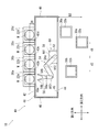
- FIG. 1 is a schematic diagram illustrating an overall configuration of a robot system according to an embodiment of the present invention. It is the schematic which shows the whole structure about the modification of the robot system which concerns on embodiment of this invention.
- FIG. 1 is a schematic diagram showing the overall configuration of a robot system according to an embodiment of the present invention.
- the robot system 10 includes four accommodating devices 20a to 20d for accommodating a semiconductor wafer W (work), and three for performing processing on the semiconductor wafer W.
- the processing devices 30a to 30c, and the transfer devices 40 disposed between the storage devices 20a to 20d and the processing devices 30a to 30c are provided.
- Each of the accommodation devices 20a to 20d may be configured as a so-called FOUP (Front Opening Unified Pod) capable of accommodating a plurality of semiconductor wafers W stacked in the vertical direction. That is, the storage devices 20a to 20d each have a hollow container body formed in a rectangular parallelepiped shape, and a container side door capable of opening and closing an opening formed on one side surface of the container body. It may be a sealed structure suitable for a clean environment.
- FOUP Front Opening Unified Pod
- the accommodation devices 20a to 20d have first placement portions 22a to 22d for placing the semiconductor wafer W, respectively.
- the first placement units 22a to 22d are configured as a part of the storage devices 20a to 20d, respectively.
- the processing performed by the processing apparatuses 30a to 30c on the semiconductor wafer W may be, for example, heat treatment, impurity introduction processing, thin film formation processing, lithography processing, cleaning processing, and etching processing.
- each of the processing apparatuses 30a to 30c may be configured as an inlet or an outlet for performing one process on the semiconductor wafer W.
- the processing apparatus 30a may be configured as an inlet for performing heat treatment on the semiconductor wafer W
- the processing apparatus 30b may be configured as the outlet.
- the processing apparatuses 30a to 30c have second mounting portions 32a to 32c for mounting the semiconductor wafer W, respectively.
- the second placement units 32a to 32c are configured as a part of the processing devices 30a to 30c, respectively.
- the transfer apparatus 40 includes a transfer apparatus internal space 41, a semiconductor wafer transfer robot 50 (hereinafter simply referred to as “robot”) for transferring the semiconductor wafer W between the accommodating apparatuses 20a to 20d and the processing apparatuses 30a to 30c. 50 ”).
- robot semiconductor wafer transfer robot 50
- the transfer device internal space 41 has a known structure in which the degree of air cleaning is ensured.
- the transfer device internal space 41 has one peripheral edge formed by a first wall 42 provided on the storage devices 20a to 20d side and a second wall 44 provided on the processing devices 30a to 30c side so as to face the first wall 42.
- the part is defined.
- the first wall 42 and the second wall 44 extend in parallel with each other in plan view.
- a direction connecting the first wall 42 and the second wall 44 is referred to as a first direction.
- a direction in which each of the first wall 42 and the second wall 44 extends (that is, a direction connecting a third wall 46 and a fourth wall 48 described later) is referred to as a second direction.
- the first wall 42 is provided with first openings 43a to 43d through which a part of the robot 50 can pass.
- the first openings 43a to 43d are formed at positions corresponding to the storage devices 20a to 20d, respectively.
- the first openings 43a to 43d may be configured to be openable and closable by providing a first room side door (not shown). Thereby, the air washing degree in the transfer apparatus internal space 41 may be ensured.
- a second opening 45 through which a part of the robot 50 can pass is formed in the second wall 44.
- the second opening 45 is formed from the vicinity of one side edge (left side edge in FIG. 1) in the second direction of the second wall 44 to the vicinity of the other side edge (right side edge in FIG. 1) in the same direction.
- the second opening 45 may be configured to be openable and closable by providing a second room side door (not shown). Thereby, the air washing degree in the transfer apparatus internal space 41 may be ensured.
- one side edge (the left side edge in FIG. 1) in the second direction of the first wall 42 and one side edge (the same front side) in the second direction of the second wall 44 are mutually connected.
- a part of the peripheral edge is further defined by a fourth wall 48 extending along the first direction so as to connect the other side edge (same as above) to each other.
- the robot 50 is a so-called horizontal articulated three-axis robot, and includes three joint axes (joint axis AX1, joint axis AX2, and joint axis AX3).
- the robot 50 includes a base 52 and a lifting shaft (not shown) that is provided on the upper surface of the base 52 and can extend and contract in the vertical direction.
- the robot 50 includes a robot arm 54 attached to the upper end of the lifting shaft, a hand 56 (end effector) attached to the tip of the robot arm 54, and a robot controller 58 that controls the robot arm 54 and the hand 56. And further.
- the elevating shaft provided on the upper surface of the base 52 is configured to be extendable and contractable by an air cylinder (not shown).
- the robot arm 54 includes a first link 54a and a second link 54b that are formed of a long member extending in the horizontal direction.
- the first link 54a is attached to the upper end of the lifting shaft at one end in the longitudinal direction via a joint axis AX1 (joint shaft provided at the base end of the robot arm) driven by a servo motor (not shown).
- the 1st link 54a is attached to the raising / lowering axis
- the second link 54b is attached to the other end portion of the first link 54a via a joint axis AX2 whose one end portion in the longitudinal direction is driven by a servo motor (not shown). Thereby, the 2nd link 54b is attached to the 1st link 54a in the state which can be rotated around the axis line extended in a perpendicular direction.
- the one end of the longitudinal direction of the hand 56 is attached to the other end of the second link 54b via a joint axis AX3 driven by a servo motor (not shown). Thereby, the hand 56 is attached to the second link 54b so as to be rotatable around an axis extending in the vertical direction.
- the hand 56 has a base portion 56a including the joint axis AX3 and a holding portion 56b attached to the distal end portion of the base portion 56a.
- the holding portion 56b is divided into two forks at the tip side, and is configured in a Y shape in plan view.
- Robot controller 58 The specific configuration of the robot control unit 58 is not particularly limited. For example, a configuration realized by a known processor (CPU or the like) operating according to a program stored in a storage unit (memory) may be used.
- a processor CPU or the like
- a storage unit memory
- the accommodating devices 20a to 20d are arranged close to the outer surface of the first wall 42 of the transfer device internal space 41, and are arranged side by side adjacent to each other.
- the first placement portions 22a to 22d are provided apart from the first wall 42 by the same first distance D1 in the first direction.
- the first distance D1 is a distance between the outer surface of the first wall 42 and the center of the semiconductor wafer W formed in a disk shape in plan view. Since each of the accommodation devices 20a to 20d is arranged close to the outer surface of the first wall 42, the end on the first wall 42 side of each of the semiconductor wafers W placed on the first placement portions 22a to 22b. The distance between the portion and the outer surface of the first wall 42 is 0 or almost 0.
- the processing devices 30a to 30b are each provided at a different distance from the second wall 44 in the first direction.
- the processing device 30a is disposed farthest from the second wall 44, the processing device 30b is disposed second farthest, and the processing device 30c is disposed closest.
- the second distance D2 from the second wall 44 to the second placement portions 32a to 32c corresponding to the first distance D1 from the first wall 42 to the first placement portions 22a to 22d is the first distance D1. This is the distance to the second placement portion 32a farthest from the second wall 44 among the second placement portions 32a to 32c in the direction. As illustrated, the second distance D2 is greater than the first distance D1. That is, the second placement portion 32a is disposed away from the second wall 44 by a second distance D2 that is farther than the first distance D1.
- the robot 50 is arranged close to the inner surface of the second wall 44.
- the joint axis AX ⁇ b> 1 arranged at the end on the second wall 44 side in the first direction of the base 52 of the robot 50 and the upper surface of the base 52 is the second wall 44. It is arranged close to the inner surface.
- the robot 50 is disposed between the second placement portion 32a farthest from the second wall 44 and the second placement portion 32b furthest away from the second wall 44 in the second direction. ing. In the present embodiment, in particular, the robot 50 is disposed at the center between the farthest second mounting part 32a and the second farthest second mounting part 32b. That is, the illustrated distance d1 and distance d2 are equal to each other.
- the joint axis AX ⁇ b> 1 arranged at the end on the second wall 44 side in the first direction of the base 52 of the robot 50 and the upper surface of the base 52 is the second wall 44.
- the second mounting portion 32a farthest from the second wall 44 and the second mounting portion 32b farthest from the second wall 44 are disposed at the center.
- the robot arm 54 is brought into a posture capable of holding the semiconductor wafer W placed on the first placement unit 22a of the accommodation apparatus 20a from the initial state.
- the robot 50 can be in the said attitude
- the semiconductor wafer W placed on the first placement unit 22a is held by the holding unit 56b of the hand 56.
- the robot arm 54 is set in a posture capable of mounting the semiconductor wafer W held by the holding unit 56b on the second mounting unit 32a of the processing apparatus 30a.
- the robot 50 is disposed close to the inner surface of the second wall 44, even the second mounting portion 32a disposed relatively far from the second wall 44 can reach with sufficient margin. Can be delivered.
- the second placement portion 32a is disposed relatively far from the second wall 44, for example, another second placement portion between the second wall 44 and the second placement portion 32a.
- the part 32a can be provided in various arrangements. Further, when the semiconductor wafer W held by the holding unit 56b is placed in a posture that allows the semiconductor wafer W to be mounted on the second mounting unit 32a of the processing apparatus 30a, the processing apparatuses 30b and 30c that may be an obstacle are appropriately avoided. Can reach you.
- the semiconductor wafer W held by the holding portion 56b is placed on the second placement portion 32a.
- the processing apparatus 30a is configured as an inlet for performing heat treatment on the semiconductor wafer W
- the processing apparatus 30b is configured as an outlet thereof.
- the robot arm 54 is set in a posture capable of holding the processed semiconductor wafer W placed on the second placement unit 32b.
- the robot 50 is arranged in the center between the second placement portion 32a farthest from the second wall 44 and the second placement portion 32b furthest away from the second wall 44 in the second direction. Therefore, the robot 50 can easily access the second placement units 32a to 32c.
- the reach of the robot 50 is less likely to reach the second placement portion 32 as the robot 50 is arranged farther from the second wall 44. Therefore, by arranging the robot 50 as described above, the robot 50 can easily access the entire second placement units 32a to 32c.
- the processed semiconductor wafer W placed on the second placement unit 32b is held by the holding unit 56b.
- the robot arm 54 is brought into a posture in which the processed semiconductor wafer W held by the holding unit 56b can be placed on the first placement unit 22b of the accommodation apparatus 20b.
- the processed semiconductor wafer W held by the holding unit 56b is placed on the first placement unit 22b.
- the semiconductor wafer W can be heat-treated using the robot system 10 according to the above embodiment.
- the robot system 10 similarly applies impurity introduction processing, thin film formation processing, lithography to the semiconductor wafer W placed on any of the accommodation devices 20a to 20d by any of the processing devices 30a to 30c. Processing, cleaning processing, planarization processing, and the like can be performed.
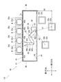
- FIG. 2 is a schematic diagram showing an overall configuration of a modified example of the robot system according to the embodiment of the present invention.
- the robot system 10 ′ according to this modification has the same structure as the robot system 10 according to the above-described embodiment except for the arrangement of the robot 50. Therefore, the same parts are denoted by the same reference numerals, and the same description will not be repeated.
- the robot 50 is arranged close to the second wall 44, and the second mount second from the distance d1 from the farthest second mounting portion 32a. It arrange
- the present invention is not limited to this case. That is, the robot 50 only needs to be arranged close to the second wall 44. Specifically, for example, only the joint axis AX ⁇ b> 1 (joint axis provided at the base end of the robot arm) is arranged close to the inner surface of the second wall 44, and a part of the base 52 moves the second wall 44. It may be arranged outside the transfer device internal space 41 across the bridge.
- the first placement unit 22 (and the storage device 20) is provided side by side by four toward the outer surface of the first wall 42 has been described, but is not limited thereto. That is, the 1st mounting part 22 may be provided 1 or more and 3 or less, and may be provided 5 or more.
- the plurality of first placement portions 22 may be provided at a different distance from the first wall 42 in the first direction. Good.
- the first distance D1 is a distance from the first wall 42 to the first placement portion 22 farthest from the first wall 42 among the plurality of first placement portions 22 in the first direction. .
- the second opening 45 is drilled from the vicinity of the one side edge in the second direction of the second wall 44 to the vicinity of the other side edge in the same direction.
- the second opening 45 may be formed at each position corresponding to the processing devices 30a to 30c in the second direction of the second wall 44.
- two or four or more second openings 45 may be formed in the second wall 44.
- each of the plurality of second openings 45 may be configured to be openable and closable by providing a second room side door.
- the several 2nd mounting part 32 may each be spaced apart and provided in the 1st direction from the 2nd wall 44 by the same distance.
- only a part of the second placement portions 32 among the plurality of second placement portions 32 is provided to be separated from the second wall 44 by the same distance, and the remaining second placement portions 32 are provided to the second wall 44. May be spaced apart from each other by a different distance.
- the second placement part 32 that is farthest from the second wall 44 and the second placement part 32 that is the second most distant from the second wall 44 are the same distance from each other. It may be separated from the wall 44.
- the plurality of second placement units 32 may have a height difference. Thereby, it is possible to further improve the degree of freedom in designing the second placement unit 32. In addition, since it is the same also about the some 1st mounting part 22, the description is not repeated here.
- the robot 50 includes the second placement portion 32a farthest from the second wall 44 and the second placement portion furthest away from the second wall 44 in the second direction. Although the case where it arrange
- the robot 50 in the second direction, is not located between the center of the second placement part 32a farthest from the second wall 44 and the second placement part 32b farthest from the second wall 44. May be arranged.
- the robot 50 may be disposed at the same position as the processing device 30 farthest from the second wall 44 in the second direction, and only needs to be disposed close to the inner surface of the second wall 44. You may arrange
- the robot arm 54 has the two links 54a and 54b has been described, but the present invention is not limited to this.
- the robot arm 54 may have three links.
- the robot arm 54 may have one or four or more links.
- the semiconductor wafer W held by the holding unit 56b of the hand 56 can be mounted on the second mounting unit 32 of the processing apparatus 30. In the posture, it is easy to reach the reach by appropriately avoiding the processing device 30 that may be an obstacle.
- the servo motor provided at one end of the first link 54a, the servo motor provided at one end of the second link 54b, and the servo motor provided at one end of the hand 56 can be independently rotated. With the configuration, the effect can be made more remarkable.
- the first placement unit 22 is configured as a part of the storage device 20 and the second placement unit 32 is configured as a part of the processing device 30. Although described, it is not limited to this.
- the first placement unit may be configured as a part of the processing device, and the second placement unit may be configured as a part of the storage device.
- the robot system 10 is applied to the semiconductor wafer manufacturing site.
- the present invention is not limited to this, and the workpiece can be moved between the first mounting unit and the second mounting unit. It may be applied to other sites that require transfer.
- the first placement unit and the second placement unit may be configured as a part of a device other than the storage device or the processing device.
- the robot 50 is placed on a wall (the first wall 42 or the second wall 44) having a large number of placement parts (the first placement part 22 or the second placement part 32) arranged in the first direction. You may be arranged near. At this time, the number of placement parts arranged at the same position in the first direction is not counted. In this way, by placing the robot 50 close to the wall with various distances from the placement unit, the degree of freedom in designing the robot system 10 can be improved.
Landscapes
- Engineering & Computer Science (AREA)
- Mechanical Engineering (AREA)
- Robotics (AREA)
- Container, Conveyance, Adherence, Positioning, Of Wafer (AREA)
- Manipulator (AREA)
Abstract
ワークを載置するための第1載置部及び第2載置部と、前記第1載置部と前記第2載置部との間に配置されている移載装置と、を備えており、前記移載装置は、前記第1載置部側に設けられる第1壁と前記第1壁に対向して前記第2載置部側に設けられる第2壁とによりその周縁の一部が画定されている移載装置内部空間と、前記第1載置部と前記第2載置部との間で前記ワークを移載するためのロボットと、を備えており、前記第1載置部は、前記第1壁と前記第2壁とを結ぶ第1方向において、前記第1壁から第1距離だけ離間して配置されており、前記第2載置部は、前記第1方向において、前記第2壁から前記第1距離よりも遠い第2距離だけ離間して配置されており、前記ロボットは、前記第2壁に寄せて配置されていることを特徴とする。
Description
本発明は、ロボットシステムに関する。
従来から、ロボットシステムが知られている。このようなロボットシステムとして、例えば、特開2013-198981号公報(特許文献1)で提案されているような基板搬送装置が知られている。
特許文献1の基板搬送装置は、準備空間に配置される基板搬送ロボットと、フープを開閉する開閉装置であるフープオープナと、準備空間に配置され、基板の向きを調整するアライナと、準備空間に満たされる気体を調整する準備空間調整装置とを含む。また、基板処理装置は、処理空間内で基板を処理する処理装置本体と、処理空間に満たされる気体を調整する処理空間調整装置とを含む。
ところで、特許文献1では、フープ及び処理装置それぞれが、準備空間の外面に寄せて配置されているが、フープ及び処理装置それぞれの配置の自由度、ひいては装置全体の設計の自由度が考慮されていない。
そこで、本発明は、設計の自由度に優れたロボットシステムを提供することを目的とする。
前記課題を解決するために、本発明に係るロボットシステムは、ワークを載置するための第1載置部及び第2載置部と、前記第1載置部と前記第2載置部との間に配置されている移載装置と、を備えており、前記移載装置は、前記第1載置部側に設けられる第1壁と前記第1壁に対向して前記第2載置部側に設けられる第2壁とによりその周縁の一部が画定されている移載装置内部空間と、前記第1載置部と前記第2載置部との間で前記ワークを移載するためのロボットと、を備えており、前記第1載置部は、前記第1壁と前記第2壁とを結ぶ第1方向において、前記第1壁から第1距離だけ離間して配置されており、前記第2載置部は、前記第1方向において、前記第2壁から前記第1距離よりも遠い第2距離だけ離間して配置されており、前記ロボットは、前記第2壁に寄せて配置されていることを特徴とする。
上記構成によれば、第2載置部は、第1壁と第2壁とを結ぶ第1方向において、第2壁から第1距離よりも遠い第2距離だけ離間して配置されており、ロボットは、第2壁に寄せて配置されている。その結果、設計の自由度に優れたロボットシステムを提供することが可能となる。
前記ロボットは、ロボットアームを有しており、前記ロボットアームの基端に設けられる関節軸が前記第2壁の内面に寄せて配置されていてもよい。
上記構成によれば、本発明に係るロボットシステムの効果を顕著にすることが可能となる。
例えば、前記第2載置部を複数備えており、前記第2距離は、前記第1方向において、前記第2壁から前記複数の第2載置部のうちで前記第2壁に対して最も遠い第2載置部までの距離であってもよい。
前記ロボットは、前記第2壁が延在する第2方向において、前記第2壁に対して最も遠い第2載置部と前記第2壁に対して2番目に遠い第2載置部との間に配置されていてもよい。
上記構成によれば、ロボットが複数の第2載置部それぞれにアクセスし易くなる。
前記ロボットは、最も遠い第2載置部からの距離と2番目に遠い第2載置部からの距離とが等しくなるように配置されていてもよい。
上記構成によれば、ロボットが複数の第2載置部それぞれにアクセスし易くなる。
例えば、前記第1載置部を複数備えており、前記第1距離は、前記第1方向において、前記第1壁から前記複数の第1載置部のうちで前記第1壁に対して最も遠い第1載置部までの距離であってもよい。
前記複数の第1載置部は、それぞれ、前記第1壁の外面に寄せて配置されていてもよい。
上記構成によれば、ロボットが複数の第1載置部それぞれにアクセスし易くなる。
前記ワークは、半導体ウェハであり、前記第1載置部は、前記半導体ウェハを収容するための収容装置の一部として構成されており、前記第2載置部は、前記半導体ウェハに対して処理を施すための処理装置の一部として構成されており、且つ、前記ロボットは、前記収容装置と前記処理装置との間で前記半導体ウェハを移載するための半導体ウェハ移載用ロボットとして構成されていてもよい。
上記構成によれば、本発明に係るロボットシステムを半導体ウェハ製造現場に適用することが可能となる。
本発明によれば、設計の自由度に優れたロボットシステムを提供することが可能となる。
以下、本発明の実施形態を添付図面に基づいて説明する。なお、以下では、全ての図を通じて同一又は相当する要素には同一の参照符号を付して、その重複する説明を省略する。
(ロボットシステム10)
図1は、本発明の実施形態に係るロボットシステムの全体構成を示す概略図である。図1に示すように、本実施形態に係るロボットシステム10は、半導体ウェハW(ワーク)を収容するための4つの収容装置20a~20dと、半導体ウェハWに対して処理を施すための3つの処理装置30a~30cと、収容装置20a~20dと処理装置30a~30cとの間に配置されている移載装置40と、を備えている。
図1は、本発明の実施形態に係るロボットシステムの全体構成を示す概略図である。図1に示すように、本実施形態に係るロボットシステム10は、半導体ウェハW(ワーク)を収容するための4つの収容装置20a~20dと、半導体ウェハWに対して処理を施すための3つの処理装置30a~30cと、収容装置20a~20dと処理装置30a~30cとの間に配置されている移載装置40と、を備えている。
(収容装置20)
収容装置20a~20dは、それぞれ、複数枚の半導体ウェハWを上下方向に積層して収容することが可能ないわゆるフープ(FOUP:Front Opening Unified Pod)として構成されていてもよい。すなわち、収容装置20a~20dは、それぞれ、直方体状に形成される中空の容器本体と、当該容器本体の一側面に形成された開口を開閉することが可能な容器側ドアとを有しており、クリーン環境に適した密閉された構造であってもよい。
収容装置20a~20dは、それぞれ、複数枚の半導体ウェハWを上下方向に積層して収容することが可能ないわゆるフープ(FOUP:Front Opening Unified Pod)として構成されていてもよい。すなわち、収容装置20a~20dは、それぞれ、直方体状に形成される中空の容器本体と、当該容器本体の一側面に形成された開口を開閉することが可能な容器側ドアとを有しており、クリーン環境に適した密閉された構造であってもよい。
収容装置20a~20dは、それぞれ、半導体ウェハWを載置するための第1載置部22a~22dを有している。換言すれば、第1載置部22a~22dは、それぞれ、収容装置20a~20dの一部として構成されている。
(処理装置30)
処理装置30a~30cが半導体ウェハWに対して施す処理は、例えば、熱処理、不純物導入処理、薄膜形成処理、リソグラフィー処理、洗浄処理及びエッチング処理などであってもよい。また、処理装置30a~30cは、それぞれ、半導体ウェハWに対して一つの処理を行うための入口又は出口として構成されていてもよい。例えば、処理装置30aが半導体ウェハWに対して熱処理を行うための入口として構成されており、処理装置30bがその出口として構成されていてもよい。
処理装置30a~30cが半導体ウェハWに対して施す処理は、例えば、熱処理、不純物導入処理、薄膜形成処理、リソグラフィー処理、洗浄処理及びエッチング処理などであってもよい。また、処理装置30a~30cは、それぞれ、半導体ウェハWに対して一つの処理を行うための入口又は出口として構成されていてもよい。例えば、処理装置30aが半導体ウェハWに対して熱処理を行うための入口として構成されており、処理装置30bがその出口として構成されていてもよい。
処理装置30a~30cは、それぞれ、半導体ウェハWを載置するための第2載置部32a~32cを有している。換言すれば、第2載置部32a~32cは、それぞれ、処理装置30a~30cの一部として構成されている。
(移載装置40)
移載装置40は、移載装置内部空間41と、収容装置20a~20dと処理装置30a~30cとの間で半導体ウェハWを移載するための半導体ウェハ移載用ロボット50(以下単に「ロボット50」という)と、を有している。
移載装置40は、移載装置内部空間41と、収容装置20a~20dと処理装置30a~30cとの間で半導体ウェハWを移載するための半導体ウェハ移載用ロボット50(以下単に「ロボット50」という)と、を有している。
(移載装置内部空間41)
移載装置内部空間41は、空気洗浄度が確保された公知の構造を有している。移載装置内部空間41は、収容装置20a~20d側に設けられる第1壁42と、第1壁42に対向して処理装置30a~30c側に設けられる第2壁44とによりその周縁の一部が画定されている。なお、第1壁42と第2壁44とは平面視において互いに平行に延在している。以下の説明において、第1壁42と第2壁44とを結ぶ方向を第1方向と称する。また、第1壁42及び第2壁44それぞれが延在する方向(すなわち、後述する第3壁46と第4壁48とを結ぶ方向)を第2方向と称する。
移載装置内部空間41は、空気洗浄度が確保された公知の構造を有している。移載装置内部空間41は、収容装置20a~20d側に設けられる第1壁42と、第1壁42に対向して処理装置30a~30c側に設けられる第2壁44とによりその周縁の一部が画定されている。なお、第1壁42と第2壁44とは平面視において互いに平行に延在している。以下の説明において、第1壁42と第2壁44とを結ぶ方向を第1方向と称する。また、第1壁42及び第2壁44それぞれが延在する方向(すなわち、後述する第3壁46と第4壁48とを結ぶ方向)を第2方向と称する。
第1壁42には、ロボット50の一部が通り抜け可能な第1開口43a~43dが穿設されている。第1開口43a~43dは、それぞれ、収容装置20a~20dに対応した位置に穿設されている。第1開口43a~43dは、それぞれ、図示しない第1ルーム側ドアが設けられることで開閉可能に構成されていてもよい。これにより、移載装置内部空間41内の空気洗浄度が確保されてもよい。
第2壁44には、ロボット50の一部が通り抜け可能な第2開口45が穿設されている。第2開口45は、第2壁44の第2方向における一方側端縁(図1において左側端縁)の近傍から同方向における他方側端縁(図1において右側端縁)の近傍まで穿設されている。第2開口45は、図示しない第2ルーム側ドアが設けられることで開閉可能に構成されていてもよい。これにより、移載装置内部空間41内の空気洗浄度が確保されてもよい。
移載装置内部空間41は、第1壁42の第2方向における一方側端縁(図1において左側端縁)と第2壁44の第2方向における一方側端縁(同前)とを互いに接続するように第1方向に沿って延在する第3壁46と、第1壁42の第2方向における他方側端縁(図1において右側端縁)と第2壁44の第2方向における他方側端縁(同前)とを互いに接続するように第1方向に沿って延在する第4壁48と、によりその周縁の一部がさらに画定されている。
(ロボット50)
本実施形態に係るロボット50は、いわゆる水平多関節型の3軸ロボットであって、3つの関節軸(関節軸AX1、関節軸AX2、及び関節軸AX3)を備えている。ロボット50は、基台52と、基台52の上面に設けられる上下方向に伸縮可能な昇降軸(図示せず)と、を備えている。
本実施形態に係るロボット50は、いわゆる水平多関節型の3軸ロボットであって、3つの関節軸(関節軸AX1、関節軸AX2、及び関節軸AX3)を備えている。ロボット50は、基台52と、基台52の上面に設けられる上下方向に伸縮可能な昇降軸(図示せず)と、を備えている。
また、ロボット50は、前記昇降軸の上端部に取り付けられるロボットアーム54と、ロボットアーム54の先端部に取り付けられるハンド56(エンドエフェクタ)と、ロボットアーム54及びハンド56を制御するロボット制御部58と、をさらに備えている。
基台52の上面に設けられる昇降軸は、図示しないエアシリンダなどで伸縮可能に構成されている。ロボットアーム54は、水平方向に延びる長尺状の部材で構成されている第1リンク54a及び第2リンク54bを含む。
第1リンク54aは、その長手方向の一端部が図示しないサーボモータで駆動する関節軸AX1(ロボットアームの基端に設けられる関節軸)を介して昇降軸の上端部に取り付けられている。これにより、第1リンク54aは鉛直方向に延びる軸線回りに回動可能な状態で昇降軸に取り付けられている。
第2リンク54bは、その長手方向の一端部が図示しないサーボモータで駆動する関節軸AX2を介して第1リンク54aの他端部に取り付けられている。これにより、第2リンク54bは鉛直方向に延びる軸線回りに回動可能な状態で第1リンク54aに取り付けられている。
ハンド56は、その長手方向の一端部が図示しないサーボモータで駆動する関節軸AX3を介して第2リンク54bの他端部に取り付けられている。これにより、ハンド56は鉛直方向に延びる軸線回りに回動可能な状態で第2リンク54bに取り付けられている。
ハンド56は、関節軸AX3を含む基部56aと、当該基部56aの先端部に取り付けられる保持部56bと、を有している。保持部56bは、その先端側が2股に分かれており、平面視においてY字状に構成されている。
(ロボット制御部58)
ロボット制御部58の具体的な構成は特に限定されないが、例えば、公知のプロセッサ(CPU等)が記憶部(メモリ)に格納されるプログラムに従って動作することにより実現される構成であってもよい。
ロボット制御部58の具体的な構成は特に限定されないが、例えば、公知のプロセッサ(CPU等)が記憶部(メモリ)に格納されるプログラムに従って動作することにより実現される構成であってもよい。
(各構成要素の配置)
ここで、上記した各構成要素の配置について詳細に説明する。収容装置20a~20dは、それぞれ、移載装置内部空間41の第1壁42の外面に寄せて配置されており、互いに横並びで隣接して配置されている。すなわち、第1載置部22a~22dは、それぞれ、第1方向において、第1壁42から同じ第1距離D1だけ離間して設けられている。
ここで、上記した各構成要素の配置について詳細に説明する。収容装置20a~20dは、それぞれ、移載装置内部空間41の第1壁42の外面に寄せて配置されており、互いに横並びで隣接して配置されている。すなわち、第1載置部22a~22dは、それぞれ、第1方向において、第1壁42から同じ第1距離D1だけ離間して設けられている。
ここで、第1距離D1は、第1壁42の外面と平面視において円板状に形成される半導体ウェハWの中心との距離である。なお、収容装置20a~20dそれぞれが第1壁42の外面に寄せて配置されているので、第1載置部22a~22bに載置されている半導体ウェハWそれぞれの第1壁42側の端部と第1壁42の外面との距離は0又はほぼ0となっている。
処理装置30a~30bは、それぞれ、第1方向において、第2壁44から互いに異なる距離だけ離間して設けられている。第2壁44に対して、最も遠くに処理装置30aが配置されており、2番目に遠くに処理装置30bが配置されており、且つ、最も近くに処理装置30cが配置されている。
ここで、上記した第1壁42から第1載置部22a~22dまでの第1距離D1に対応した第2壁44から第2載置部32a~32cまでの第2距離D2は、第1方向において、第2載置部32a~32cのうちで第2壁44に対して最も遠い第2載置部32aまでの距離である。図示するように、第2距離D2は、第1距離D1よりも大きい。すなわち、第2載置部32aは、第2壁44から第1距離D1よりも遠い第2距離D2だけ離間して配置されている。
ロボット50は、第2壁44の内面に寄せて配置されている。具体的には、本実施形態では、ロボット50の基台52及び当該基台52の上面の第1方向における第2壁44側の端部に配されている関節軸AX1が、第2壁44の内面に寄せて配置されている。
また、ロボット50は、第2方向において、第2壁44に対して最も遠い第2載置部32aと第2壁44に対して2番目に遠い第2載置部32bとの間に配置されている。本実施形態では、特に、ロボット50は、前記最も遠い第2載置部32aと前記2番目に遠い第2載置部32bとの中央に配置されている。すなわち、図示する距離d1と距離d2は互いに等しい。
具体的には、本実施形態では、ロボット50の基台52及び当該基台52の上面の第1方向における第2壁44側の端部に配されている関節軸AX1が、第2壁44に対して最も遠い第2載置部32aと第2壁44に対して2番目に遠い第2載置部32bとの中央に配置されている。
(半導体ウェハWに対する処理工程の一例及び効果)
ここで、上記施形態に係るロボットシステム10を用いて、半導体ウェハWに対して行われる熱処理工程の一例について説明する。また、上記実施形態に係るロボットシステム10により奏する効果についてもあわせて説明する。
ここで、上記施形態に係るロボットシステム10を用いて、半導体ウェハWに対して行われる熱処理工程の一例について説明する。また、上記実施形態に係るロボットシステム10により奏する効果についてもあわせて説明する。
まず、ロボットアーム54を、初期状態から収容装置20aの第1載置部22aに載置されている半導体ウェハWを保持することが可能な姿勢にする。なお、第1壁42に穿設された第1開口43aをハンド56が通り抜けることで、ロボット50を前記姿勢にすることができる。
次に、ハンド56の保持部56bにより第1載置部22aに載置されている半導体ウェハWを保持する。
さらに、ロボットアーム54を、保持部56bにより保持している半導体ウェハWを処理装置30aの第2載置部32aに載置することが可能な姿勢にする。
このとき、ロボット50は、第2壁44の内面に寄せて配置されているので、第2壁44に対して比較的遠くに配置される第2載置部32aであっても余裕をもってリーチを届かせることができる。また、第2壁44に対して比較的遠くに第2載置部32aを配置しているので、例えば、第2壁44と前記第2載置部32aとの間に他の第2載置部32aを多様な配置で設けることが可能となる。さらに、保持部56bにより保持している半導体ウェハWを処理装置30aの第2載置部32aに載置することが可能な姿勢とする際に、妨げとなり得る処理装置30b、30cを適切に避けてリーチを届かせることができる。
上記の通りであるため、第2載置部32の配置の自由度に優れたロボットシステム10、ひいては設計の自由度に優れたロボットシステム10を提供することが可能となる。
そして、保持部56bにより保持している半導体ウェハWを第2載置部32aに載置する。
次に、半導体ウェハWに対して熱処理を行う。熱処理を行った後の半導体ウェハWは処理装置30bの第2載置部32bに載置される。すなわち、ここでは、処理装置30aが半導体ウェハWに対して熱処理を行うための入口として構成されており、処理装置30bがその出口として構成されている。
さらに、ロボットアーム54を、第2載置部32bに載置されている処理済みの半導体ウェハWを保持することが可能な姿勢にする。
このとき、ロボット50は、第2方向において、第2壁44に対して最も遠い第2載置部32aと第2壁44に対して2番目に遠い第2載置部32bとの中央に配置されているので、ロボット50が第2載置部32a~32cそれぞれにアクセスし易くなる。
なお、ロボット50は、第2壁44から遠くに配置されるほど第2載置部32にリーチが届きにくくなる。したがって、ロボット50を前記のように配置することで、ロボット50が第2載置部32a~32c全体に対してアクセスし易くなる。
そして、保持部56bにより第2載置部32bに載置されている処理済みの半導体ウェハWを保持する。
次に、ロボットアーム54を、保持部56bにより保持している処理済みの半導体ウェハWを収容装置20bの第1載置部22bに載置することが可能な姿勢にする。
さらに、保持部56bにより保持している処理済みの半導体ウェハWを第1載置部22bに載置する。
以上のように、上記施形態に係るロボットシステム10を用いて、半導体ウェハWに対して熱処理を行うことができる。なお、ロボットシステム10は、同様にして、収容装置20a~20dのいずれかに載置されている半導体ウェハWに対して、処理装置30a~30cのいずれかで不純物導入処理、薄膜形成処理、リソグラフィー処理、洗浄処理及び平坦化処理などを行うことができる。
(変形例)
上記説明から、当業者にとっては、本発明の多くの改良や他の実施形態が明らかである。したがって、上記説明は、例示としてのみ解釈されるべきであり、本発明を実行する最良の態様を当業者に教示する目的で提供されたものである。本発明の精神を逸脱することなく、その構造及び/又は機能の詳細を実質的に変更できる。
上記説明から、当業者にとっては、本発明の多くの改良や他の実施形態が明らかである。したがって、上記説明は、例示としてのみ解釈されるべきであり、本発明を実行する最良の態様を当業者に教示する目的で提供されたものである。本発明の精神を逸脱することなく、その構造及び/又は機能の詳細を実質的に変更できる。
図2は、本発明の実施形態に係るロボットシステムの変形例についての全体構成を示す概略図である。なお、本変形例に係るロボットシステム10´は、ロボット50の配置を除いて、上記実施形態に係るロボットシステム10と同じ構造である。したがって、同一部分には同じ参照番号を付し、同様となる説明は繰り返さない。
図2に示すように、本変形例では、ロボット50は、第2壁44に寄せて配置されており、且つ、最も遠い第2載置部32aからの距離d1と2番目に遠い第2載置部32bからの距離d2とが等しくなるように配置されている。このようにロボット50を配置しても、上記実施形態の場合と同様に、第2載置部32の配置の自由度に優れたロボットシステム10´、ひいては設計の自由度に優れたロボットシステム10´を提供することが可能となる。
上記実施形態及びその変形例では、ロボット50の基台52及び関節軸AX1が、第2壁44の内面に寄せて配置されている場合について説明したが、この場合に限定されない。すなわち、ロボット50は、第2壁44に寄せて配置されていればよい。具体的には、例えば、関節軸AX1(ロボットアームの基端に設けられる関節軸)のみが第2壁44の内面に寄せて配置されており、基台52の一部が第2壁44を跨いで移載装置内部空間41の外部に配置されていてもよい。
上記実施形態及びその変形例では、第1載置部22(及び収容装置20)が第1壁42の外面に寄せて横並びに4つ設けられている場合について説明したが、これに限定されない。すなわち、第1載置部22は、1つ以上3つ以下設けられていてもよいし、5つ以上設けられていてもよい。
なお、第1載置部22が複数設けられている場合、複数の第1載置部22は、それぞれ、第1方向において、第1壁42から互いに異なる距離だけ離間して設けられていてもよい。このとき、第1距離D1は、第1方向において、第1壁42から複数の第1載置部22のうちで第1壁42に対して最も遠い第1載置部22までの距離である。
上記実施形態及びその変形例では、第2開口45は、第2壁44の第2方向における一方側端縁の近傍から同方向における他方側端縁の近傍まで穿設されている場合について説明したが、これに限定されない。例えば、第2開口45は、第2壁44の第2方向における処理装置30a~30cに対応した位置それぞれに穿設されていてもよい。また、第2開口45は、第2壁44に2つ又は4つ以上穿設されていてもよい。このとき、複数の第2開口45は、それぞれ、第2ルーム側ドアが設けられることで開閉可能に構成されていてもよい。
上記実施形態及びその変形例では、第2載置部32(及び処理装置30)が第2壁44から互いに異なる距離だけ離間して3つ設けられている場合について説明したが、これに限定されない。すなわち、第2載置部32は、1つ又は2つ設けられていてもよいし、4つ以上設けられていてもよい。
なお、第2載置部32が複数設けられている場合、複数の第2載置部32は、それぞれ、第1方向において、第2壁44から同じ距離だけ離間して設けられていてもよい。さらに、複数の第2載置部32のうちの一部の第2載置部32のみ第2壁44から同じ距離だけ離間して設けられ、残りの第2載置部32は第2壁44から互いに異なる距離だけ離間して設けられていてもよい。このとき、第2方向において、第2壁44に対して最も遠い第2載置部32と第2壁44に対して2番目に遠い第2載置部32とは、互いに同じ距離だけ第2壁44から離間していてもよい。
また、第2載置部32が複数設けられている場合、複数の第2載置部32は、それぞれ、高低差があってもよい。これにより、第2載置部32の設計の自由度をさらに向上させることが可能となる。なお、複数の第1載置部22についても同様であるため、ここではその説明を繰り返さない。
上記実施形態及びその変形例では、ロボット50は、第2方向において、第2壁44に対して最も遠い第2載置部32aと第2壁44に対して2番目に遠い第2載置部32bとの中央に配置される場合について説明したが、これに限定されない。
例えば、ロボット50は、第2方向において、第2壁44に対して最も遠い第2載置部32aと第2壁44に対して2番目に遠い第2載置部32bとの中央以外の間に配置されていてもよい。また、例えば、ロボット50は、第2方向において、第2壁44から最も遠い処理装置30と同じ位置に配置されていてもよいし、第2壁44の内面に寄せて配置されてさえいれば他の位置に配置されていてもよい。
上記実施形態及びその変形例では、ロボットアーム54が2つのリンク54a、54bを有している場合について説明したが、これに限定されない。例えば、ロボットアーム54は、3つのリンクを有していてもよい。また、ロボットアーム54は、1つ又は4つ以上のリンクを有していてもよい。
なお、ロボットアーム54のリンクの数を多くすることで、例えば、ハンド56の保持部56bにより保持している半導体ウェハWを処理装置30の第2載置部32に載置することが可能な姿勢とする際に、妨げとなり得る処理装置30を適切に避けてリーチを届かせることが容易となる。
また、第1リンク54aの一端部に設けられるサーボモータ、第2リンク54bの一端部に設けられるサーボモータ、及びハンド56の一端部に設けられるサーボモータを、それぞれ、独立して回動可能な構成とすることで、前記効果をいっそう顕著にすることが可能となる。
上記実施形態及びその変形例では、第1載置部22が収容装置20の一部として構成されており、且つ、第2載置部32が処理装置30の一部として構成されている場合について説明したが、これに限定されない。例えば、第1載置部が処理装置の一部として構成されており、第2載置部が収容装置の一部として構成されていてもよい。
上記実施形態及びその変形例では、ロボットシステム10が半導体ウェハ製造現場に適用される場合について説明したが、これに限定されず、第1載置部と第2載置部との間でワークの移載を要する他の現場に適用されてもよい。このような場合、第1載置部及び第2載置部は収容装置や処理装置以外の装置の一部として構成されていてもよい。
さらに、例えば、ロボット50は、第1方向において並んでいる載置部(第1載置部22又は第2載置部32)の数が多い壁(第1壁42又は第2壁44)に寄せて配置されていてもよい。このとき、第1方向において互いに同じ位置に配置されている載置部の数はカウントしない。このように、載置部との距離が多様な壁に寄せてロボット50を配置することで、ロボットシステム10の設計の自由度を向上させることが可能となる。
10 ロボットシステム
20 収容装置
22 第1載置部
30 処理装置
32 第2載置部
40 移載装置
41 移載装置内部空間
42 第1壁
43 第1開口
44 第2壁
45 第2開口
50 ロボット
52 基台
54 ロボットアーム
56 ハンド
58 ロボット制御部
AX 関節軸
W 半導体ウェハ
20 収容装置
22 第1載置部
30 処理装置
32 第2載置部
40 移載装置
41 移載装置内部空間
42 第1壁
43 第1開口
44 第2壁
45 第2開口
50 ロボット
52 基台
54 ロボットアーム
56 ハンド
58 ロボット制御部
AX 関節軸
W 半導体ウェハ
Claims (8)
- ワークを載置するための第1載置部及び第2載置部と、
前記第1載置部と前記第2載置部との間に配置されている移載装置と、を備えており、
前記移載装置は、
前記第1載置部側に設けられる第1壁と前記第1壁に対向して前記第2載置部側に設けられる第2壁とによりその周縁の一部が画定されている移載装置内部空間と、
前記第1載置部と前記第2載置部との間で前記ワークを移載するためのロボットと、を備えており、
前記第1載置部は、前記第1壁と前記第2壁とを結ぶ第1方向において、前記第1壁から第1距離だけ離間して配置されており、
前記第2載置部は、前記第1方向において、前記第2壁から前記第1距離よりも遠い第2距離だけ離間して配置されており、
前記ロボットは、前記第2壁に寄せて配置されていることを特徴とする、ロボットシステム。 - 前記ロボットは、ロボットアームを有しており、前記ロボットアームの基端に設けられる関節軸が前記第2壁の内面に寄せて配置されている、請求項1に記載のロボットシステム。
- 前記第2載置部を複数備えており、
前記第2距離は、前記第1方向において、前記第2壁から前記複数の第2載置部のうちで前記第2壁に対して最も遠い第2載置部までの距離である、請求項1又は2に記載のロボットシステム。 - 前記ロボットは、前記第2壁が延在する第2方向において、前記第2壁に対して最も遠い第2載置部と前記第2壁に対して2番目に遠い第2載置部との間に配置されている、請求項3に記載のロボットシステム。
- 前記ロボットは、最も遠い第2載置部からの距離と2番目に遠い第2載置部からの距離とが等しくなるように配置されている、請求項3又は4に記載のロボットシステム。
- 前記第1載置部を複数備えており、
前記第1距離は、前記第1方向において、前記第1壁から前記複数の第1載置部のうちで前記第1壁に対して最も遠い第1載置部までの距離である、請求項1乃至5のいずれかに記載のロボットシステム。 - 前記複数の第1載置部は、それぞれ、前記第1壁の外面に寄せて配置されている、請求項6に記載のロボットシステム。
- 前記ワークは、半導体ウェハであり、
前記第1載置部は、前記半導体ウェハを収容するための収容装置の一部として構成されており、
前記第2載置部は、前記半導体ウェハに対して処理を施すための処理装置の一部として構成されており、且つ、
前記ロボットは、前記収容装置と前記処理装置との間で前記半導体ウェハを移載するための半導体ウェハ移載用ロボットとして構成されている、請求項1乃至7のいずれかに記載のロボットシステム。
Priority Applications (2)
| Application Number | Priority Date | Filing Date | Title |
|---|---|---|---|
| CN201980026301.2A CN111937131A (zh) | 2018-05-29 | 2019-05-28 | 机器人系统 |
| US17/059,492 US20210233796A1 (en) | 2018-05-29 | 2019-05-28 | Robot system |
Applications Claiming Priority (2)
| Application Number | Priority Date | Filing Date | Title |
|---|---|---|---|
| JP2018102160A JP2019207930A (ja) | 2018-05-29 | 2018-05-29 | ロボットシステム |
| JP2018-102160 | 2018-05-29 |
Publications (1)
| Publication Number | Publication Date |
|---|---|
| WO2019230711A1 true WO2019230711A1 (ja) | 2019-12-05 |
Family
ID=68698842
Family Applications (1)
| Application Number | Title | Priority Date | Filing Date |
|---|---|---|---|
| PCT/JP2019/021064 Ceased WO2019230711A1 (ja) | 2018-05-29 | 2019-05-28 | ロボットシステム |
Country Status (5)
| Country | Link |
|---|---|
| US (1) | US20210233796A1 (ja) |
| JP (1) | JP2019207930A (ja) |
| CN (1) | CN111937131A (ja) |
| TW (1) | TWI716888B (ja) |
| WO (1) | WO2019230711A1 (ja) |
Cited By (1)
| Publication number | Priority date | Publication date | Assignee | Title |
|---|---|---|---|---|
| CN115066744A (zh) * | 2020-02-07 | 2022-09-16 | 川崎重工业株式会社 | 机器人以及包括机器人的基板运送系统 |
Families Citing this family (1)
| Publication number | Priority date | Publication date | Assignee | Title |
|---|---|---|---|---|
| US20240379396A1 (en) * | 2023-05-10 | 2024-11-14 | Brooks Automation US, LLC. | Substrate processing apparatus |
Citations (3)
| Publication number | Priority date | Publication date | Assignee | Title |
|---|---|---|---|---|
| JP2008028134A (ja) * | 2006-07-20 | 2008-02-07 | Kawasaki Heavy Ind Ltd | ウェハ移載装置および基板移載装置 |
| JP2012169690A (ja) * | 2007-11-21 | 2012-09-06 | Yaskawa Electric Corp | 筐体および半導体製造装置 |
| JP2018073942A (ja) * | 2016-10-27 | 2018-05-10 | 川崎重工業株式会社 | 基板把持ハンド及びそれを備える基板搬送装置 |
Family Cites Families (3)
| Publication number | Priority date | Publication date | Assignee | Title |
|---|---|---|---|---|
| TWI398335B (zh) * | 2006-11-27 | 2013-06-11 | 日本電產三協股份有限公司 | Workpiece conveying system |
| JP5569544B2 (ja) * | 2012-01-31 | 2014-08-13 | 株式会社安川電機 | 搬送ロボット |
| US10822698B2 (en) * | 2015-08-31 | 2020-11-03 | Asm Ip Holding B.V. | Substrate processing apparatus, recording medium, and method of processing substrates |
-
2018
- 2018-05-29 JP JP2018102160A patent/JP2019207930A/ja active Pending
-
2019
- 2019-05-28 WO PCT/JP2019/021064 patent/WO2019230711A1/ja not_active Ceased
- 2019-05-28 CN CN201980026301.2A patent/CN111937131A/zh active Pending
- 2019-05-28 US US17/059,492 patent/US20210233796A1/en not_active Abandoned
- 2019-05-29 TW TW108118489A patent/TWI716888B/zh active
Patent Citations (3)
| Publication number | Priority date | Publication date | Assignee | Title |
|---|---|---|---|---|
| JP2008028134A (ja) * | 2006-07-20 | 2008-02-07 | Kawasaki Heavy Ind Ltd | ウェハ移載装置および基板移載装置 |
| JP2012169690A (ja) * | 2007-11-21 | 2012-09-06 | Yaskawa Electric Corp | 筐体および半導体製造装置 |
| JP2018073942A (ja) * | 2016-10-27 | 2018-05-10 | 川崎重工業株式会社 | 基板把持ハンド及びそれを備える基板搬送装置 |
Cited By (2)
| Publication number | Priority date | Publication date | Assignee | Title |
|---|---|---|---|---|
| CN115066744A (zh) * | 2020-02-07 | 2022-09-16 | 川崎重工业株式会社 | 机器人以及包括机器人的基板运送系统 |
| CN115066744B (zh) * | 2020-02-07 | 2026-04-21 | 川崎重工业株式会社 | 机器人以及包括机器人的基板运送系统 |
Also Published As
| Publication number | Publication date |
|---|---|
| JP2019207930A (ja) | 2019-12-05 |
| US20210233796A1 (en) | 2021-07-29 |
| CN111937131A (zh) | 2020-11-13 |
| TWI716888B (zh) | 2021-01-21 |
| TW202003362A (zh) | 2020-01-16 |
Similar Documents
| Publication | Publication Date | Title |
|---|---|---|
| JP5853991B2 (ja) | 基板搬送ロボット、基板搬送システムおよび基板搬送方法 | |
| JP7370233B2 (ja) | 基板搬送装置及び基板処理システム | |
| US10910240B2 (en) | Substrate processing device | |
| WO2021245956A1 (ja) | ウエハ搬送装置、およびウエハ搬送方法 | |
| KR20080008981A (ko) | 웨이퍼 이재 장치 및 기판 이재 장치 | |
| KR101453189B1 (ko) | 반송 장치 | |
| US12434378B2 (en) | Horizontal articulated robot and substrate transfer system comprising same | |
| US11538705B2 (en) | Plasma processing system and operating method of the same | |
| JP7841197B2 (ja) | 基板搬送ロボット | |
| US11443972B2 (en) | Substrate processing apparatus | |
| JP6492271B2 (ja) | 搬送システムおよびロボット | |
| JP2019207930A (ja) | ロボットシステム | |
| JP4746027B2 (ja) | 基板搬送方法 | |
| JP6296164B2 (ja) | ロボットシステムおよび搬送方法 | |
| JP2008103755A5 (ja) | ||
| US20250022736A1 (en) | Substrate transport system and transfer robot control device | |
| US20250018578A1 (en) | Substrate transport system and transfer robot | |
| KR20220139945A (ko) | 로봇 및 이를 구비한 기판 반송 시스템 | |
| JP6378595B2 (ja) | 基板搬送装置 | |
| JP7662388B2 (ja) | 基板搬送ロボットおよび基板搬送装置 | |
| JP2011108923A (ja) | 真空処理装置 | |
| JP6649995B2 (ja) | 基板搬送ロボット | |
| WO2021206071A1 (ja) | 真空用双腕ロボット | |
| JP7407067B2 (ja) | 搬送装置、搬送方法および搬送システム | |
| JP2026019371A (ja) | ロボットシステム |
Legal Events
| Date | Code | Title | Description |
|---|---|---|---|
| 121 | Ep: the epo has been informed by wipo that ep was designated in this application |
Ref document number: 19811335 Country of ref document: EP Kind code of ref document: A1 |
|
| DPE1 | Request for preliminary examination filed after expiration of 19th month from priority date (pct application filed from 20040101) | ||
| NENP | Non-entry into the national phase |
Ref country code: DE |
|
| 122 | Ep: pct application non-entry in european phase |
Ref document number: 19811335 Country of ref document: EP Kind code of ref document: A1 |