WO2019230409A1 - 携帯端末位置判定装置 - Google Patents
携帯端末位置判定装置 Download PDFInfo
- Publication number
- WO2019230409A1 WO2019230409A1 PCT/JP2019/019431 JP2019019431W WO2019230409A1 WO 2019230409 A1 WO2019230409 A1 WO 2019230409A1 JP 2019019431 W JP2019019431 W JP 2019019431W WO 2019230409 A1 WO2019230409 A1 WO 2019230409A1
- Authority
- WO
- WIPO (PCT)
- Prior art keywords
- communication
- mobile terminal
- strength
- seat
- portable terminal
- Prior art date
- Legal status (The legal status is an assumption and is not a legal conclusion. Google has not performed a legal analysis and makes no representation as to the accuracy of the status listed.)
- Ceased
Links
Images




Classifications
-
- G—PHYSICS
- G01—MEASURING; TESTING
- G01S—RADIO DIRECTION-FINDING; RADIO NAVIGATION; DETERMINING DISTANCE OR VELOCITY BY USE OF RADIO WAVES; LOCATING OR PRESENCE-DETECTING BY USE OF THE REFLECTION OR RERADIATION OF RADIO WAVES; ANALOGOUS ARRANGEMENTS USING OTHER WAVES
- G01S5/00—Position-fixing by co-ordinating two or more direction or position line determinations; Position-fixing by co-ordinating two or more distance determinations
- G01S5/02—Position-fixing by co-ordinating two or more direction or position line determinations; Position-fixing by co-ordinating two or more distance determinations using radio waves
- G01S5/0269—Inferred or constrained positioning, e.g. employing knowledge of the physical or electromagnetic environment, state of motion or other contextual information to infer or constrain a position
-
- H—ELECTRICITY
- H04—ELECTRIC COMMUNICATION TECHNIQUE
- H04M—TELEPHONIC COMMUNICATION
- H04M1/00—Substation equipment, e.g. for use by subscribers
-
- H—ELECTRICITY
- H04—ELECTRIC COMMUNICATION TECHNIQUE
- H04W—WIRELESS COMMUNICATION NETWORKS
- H04W4/00—Services specially adapted for wireless communication networks; Facilities therefor
- H04W4/30—Services specially adapted for particular environments, situations or purposes
- H04W4/40—Services specially adapted for particular environments, situations or purposes for vehicles, e.g. vehicle-to-pedestrians [V2P]
- H04W4/48—Services specially adapted for particular environments, situations or purposes for vehicles, e.g. vehicle-to-pedestrians [V2P] for in-vehicle communication
Definitions
- the present invention relates to a mobile terminal position determination device.
- Patent Documents 1 and 2 Conventionally, a technique for restricting the driver's mobile terminal operation has been proposed (see, for example, Patent Documents 1 and 2).
- the radio wave reception level is measured by switching the antenna near the driver seat and the antenna near the passenger seat, and the antenna near the driver seat receives the reception level.
- the radio wave is high, it is determined that the radio wave is transmitted from the driver's seat, and the execution of the operation command included in the radio wave is restricted.
- Patent Document 2 See paragraph [0058] of the same document
- signal sources are installed in the driver's seat and the passenger's seat, and the portable terminal receives signals from these signal sources and uses the portable terminal.
- a means for determining the location is arranged, and the means measures the intensity of each received signal.
- the means measures the intensity of each received signal.
- An object of the present invention is to provide a mobile terminal position determination device that can improve the determination accuracy of the mobile terminal position.
- the mobile terminal position determination apparatus includes at least two communication units arranged at different positions that communicate with a mobile terminal, and a communication strength measurement unit that measures communication strength of communication between the mobile terminal and each of the communication units. And a position determination means for determining the position of the portable terminal by comparing the ratio of the two communication strengths measured by the communication strength measurement means with a corresponding threshold value.
- the ratio of the two is used to determine how much one of the two communication strengths is greater than the other. And the position of the mobile terminal is determined based on comparing the ratio with a corresponding threshold value. Therefore, the determination accuracy of the portable terminal position can be improved.
- the said at least 2 communication part is good also as having at least 3 communication part.
- the communication strength of communication with the mobile terminal is measured by the number of communication units, and the position of the mobile terminal is determined based on comparing the ratio of the respective communication strengths with the corresponding threshold value. Thereby, the position of the portable terminal can be determined with high accuracy.
- At least 1 of the said communication part is arrange
- the said position determination means is good also as calculating ratio using the maximum communication intensity
- the communication strength in the communication unit far from the mobile terminal is not used, and the communication strength (maximum communication strength) in the communication unit closest to the mobile terminal is used. Is calculated. Thereby, the position of the portable terminal can be determined with high accuracy.
- the mobile terminal position determination device of one embodiment is arranged at a first position and communicates with the mobile terminal, and a sub-communication that is arranged at a second position different from the first position and communicates with the mobile terminal.
- Communication strength measuring means for measuring the communication strength between the main communication unit and the portable terminal as a first communication strength and measuring the communication strength between the sub-communication unit and the portable terminal as a second communication strength.
- a position determination means for determining a position of the mobile terminal by comparing a ratio between the first communication strength and the second communication strength with a threshold value associated with the main communication unit and the sub communication unit.
- the position of the mobile terminal is determined based on comparing the ratio between the first communication strength and the second communication strength with a threshold associated with the main communication unit and the sub communication unit.
- the main communication unit may be one of at least one main communication unit arranged at the first position.
- the sub communication unit may be one of at least two sub communication units arranged at the second position.
- the communication strength measuring means measures the strength of communication between the at least one main communication unit and the portable terminal as at least one first communication strength, and communicates between the at least two sub communication units and the portable terminal. Can be measured as at least two second communication strengths.
- the position determination means compares the ratio of each of the first communication strength and each of the second communication strengths with a corresponding threshold value associated with the corresponding main communication unit and the corresponding sub communication unit.
- the position of the mobile terminal can be determined. According to this configuration, by using at least one main communication unit and at least two sub-communication units, the ratio of each first communication strength and each second communication strength is compared with a corresponding threshold value, so that the mobile terminal The position of is determined. Thereby, the determination precision of a portable terminal position can be improved.
- a plurality of beacons (signal sources) 11 and 21 to 23 for transmitting radio signals are installed in the vehicle 1.
- the beacon 11 is installed at the door of the driver's seat (D seat)
- the beacon 21 is installed at the door of the passenger seat (P seat)
- the beacon 22 is installed at the door of the rear left seat (RL seat)
- the beacon 23 is rear It is installed at the door of the right seat (RR seat).
- the beacon 11 is a driver's seat beacon
- the other beacons 21 to 23 are passenger seat beacons. Any of the beacons 11, 21 to 23 transmits a radio signal including the vehicle ID and the seat position.
- the vehicle ID is a unique ID of the vehicle 1, and by transmitting a radio signal including this vehicle ID from the beacons 11 and 21 to 23 of the vehicle 1, on the receiving side, a radio signal from another vehicle is transmitted. A distinction is possible.
- the vehicle 1 is provided with a parking brake 32 and a vehicle speed sensor 33.
- the in-vehicle controller 31 transmits the parking brake ON / OFF signal acquired from the parking brake 32 and the vehicle speed signal acquired from the vehicle speed sensor 33 to the portable terminal 5 by Bluetooth (registered trademark) or the like.
- the mobile terminal 5 is a so-called smart phone (high performance mobile phone) possessed by the user, and has a telephone function and a mail function, a Bluetooth communication function, and a function of receiving radio signals from the beacons 11 and 21 to 23. ing.
- the mobile terminal 5 receives a wireless signal from the beacon 11 and 21 to 23, as well as the first communication unit 52 responsible for the Bluetooth communication function, in addition to the terminal control unit 51 that controls the overall control of the terminal 5 itself. And a communication unit 53.
- the second communication unit 53 measures the intensity of the received radio signal and outputs the measurement result to the terminal control unit 51.
- the terminal control unit 51 determines (estimates) the position of the terminal 5 based on the measurement result of the received signal strength.
- the second communication unit 53 corresponds to communication strength measuring means for measuring the communication strength (reception signal strength) of communication between the mobile terminal 5 and the communication units (beacons 11, 21 to 23), and the terminal control unit 51 Corresponds to position determination means. Furthermore, in this example, the combination of the portable terminal 5 including these means and the communication unit (in this example, the beacons 11, 21 to 23) corresponds to the portable terminal position determination device.
- the terminal control unit 51 determines that the position of the terminal 5 is the driver's seat based on the measurement result of the received signal strength, and the parking brake ON / OFF signal received by the first communication unit 52. If it is determined that the vehicle is traveling based on the vehicle speed signal, the mobile terminal 5 is set to the driver mode. In the driver mode, the functions of the portable terminal 5 that can be used are limited.
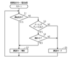
- the terminal control unit 51 determines whether or not the position of the own terminal 5 is other than the driver's seat in step S1. And terminal control part 51 cancels driver mode, when it judges that the position of self-terminal 5 is other than a driver's seat (it is YES at Step S1) (Step S2). Accordingly, the function restriction is released for the portable terminal 5 (passenger's portable terminal 5) in the passenger seat or the rear seat.
- step S3 determines whether or not the parking brake is ON. If the terminal control unit 51 determines that the parking brake is ON (YES in step S3), the terminal control unit 51 determines whether or not the vehicle speed is zero (step S4). When the terminal control unit 51 determines that the vehicle speed is zero (YES in step S4), the terminal control unit 51 cancels the driver mode (step S2). Thereby, even if it is the portable terminal 5 of a driver's seat, when not driving
- the terminal control unit 51 determines that the parking brake is OFF (NO in step S3) or the vehicle speed is not zero (NO in step S4), the terminal control unit 51 sets the portable terminal 5 to the driver mode (step S5). As a result, usable functions are limited for the mobile terminal 5 near the driver's seat while traveling.
- the terminal control unit 51 determines whether or not the vehicle ID included in the wireless signal matches the vehicle ID registered in the terminal 5, and confirms that the vehicle ID matches. Depending on the condition, the process may proceed to step S1.
- the mobile terminal 5 is actually located outside the driver's seat of the own vehicle, There is no inconvenience that a usable function is limited due to erroneous determination that the vehicle is in the driver's seat of another vehicle based on a radio signal from the other vehicle. That is, erroneous determination can be prevented by distinguishing from other vehicles by using the vehicle ID.
- the position determination logic of the terminal 5 by the terminal control unit 51 will be described.
- the received signal strength of the radio signal from the driver's seat beacon (beacon 11) is set to Ed
- the received signal strength of the radio signal from each passenger seat beacon (beacons 21 to 23) is set to Ep (n).
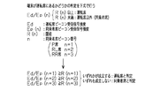
- the terminal control unit 51 calculates Ed / Ep (n), and determines the position of the terminal 5 based on whether the value (ratio) is equal to or greater than the threshold value R (n).
- n is the passenger seat beacon number, and for convenience, the passenger seat beacon number of the P seat beacon 21 is “1”.
- the passenger seat beacon number of the RL seat beacon 22 is set to “2”
- the passenger seat beacon number of the RR seat beacon 23 is set to “3”.
- the driver's seat (D seat) corresponds to the first position (area where the position of the mobile terminal 5 is determined), and the passenger seat (P seat, RL seat, RR seat) corresponds to the second position.
- Ed corresponds to the first received signal strength derived from the beacon 11 at the first position
- Ep (n) corresponds to the second received signal strength derived from the beacons 21 to 23 at the second position.
- the terminal control unit 51 calculates the ratio between the first received signal strength Ed and the second received signal strength Ep (n), and compares the ratio with the threshold value R (n). Will be judged. Furthermore, the terminal control unit 51 always uses the first received signal strength Ed to calculate the ratio with the second received signal strength Ep (n).
- the beacons 11, 21 to 23 correspond to at least two communication units arranged at different positions communicating with the mobile terminal 5, and in this example, the beacon 11 calculates the ratio of received signal strengths among them. It corresponds to the essential main communication unit, and the other beacons 21 to 23 correspond to the sub communication unit.
- the mobile terminal position determination device does not simply determine which is greater between the first received signal strength Ed and the second received signal strength Ep (n), but to determine which is greater, And the position of the portable terminal 5 is determined based on comparing the ratio with the threshold value R (n). Therefore, the accuracy of determining the position of the mobile terminal 5 can be improved.
- the mobile terminal position determination device measures the communication strength (reception signal strength) of communication with the mobile terminal 5 by the number of beacons 11, 21 to 23, and sets the ratio of the respective communication strengths as a threshold value R (n). Based on the comparison, the position of the mobile terminal 5 is determined. Thereby, the position of the portable terminal 5 can be determined with high accuracy.
- the mobile terminal position determination device always calculates the ratio using the first received signal strength Ed by the mobile terminal 5 and the driver's seat beacon (beacon 11 as the main communication unit), and sets the ratio as a threshold value R (n). Based on the comparison, it can be accurately determined whether or not the portable terminal 5 is in the driver's seat.
- the mobile terminal position determination device uses the vehicle ID to determine the position of the mobile terminal 5 only when the vehicle IDs match and does not determine the position of the mobile terminal 5 when the vehicle IDs do not match. An erroneous determination of the position of the mobile terminal 5 can be prevented.
- a beacon 12 that is a driver's seat beacon is installed in the vehicle 2 in addition to a plurality of beacons 11 and 21 to 23 similar to those in the first embodiment.
- the beacon 11 is installed on the door of the driver's seat (D seat), whereas the beacon 12 is installed near the passenger seat (P seat) of the D seat.
- the operation of the mobile terminal position determination device will be described. Since the mode setting process executed by the terminal control unit 51 of the portable terminal 5 is the same as that in the first embodiment (see FIG. 2), the description is omitted, and the position determination logic of the terminal 5 by the terminal control unit 51 is omitted. Will be described.
- the received signal strength of the radio signal from each driver's seat beacon is Ed (m), and the received signal of the radio signal from each passenger seat beacon (beacons 21 to 23).
- the intensity is set to Ep (n).
- the terminal control unit 51 calculates Ed (m) / Ep (n), and determines the position of the terminal 5 based on whether the value (ratio) is equal to or greater than the threshold value R (m, n). judge.
- m is a driver's seat beacon number.
- the driver's seat beacon number of the beacon 11 of the D seat door is “1”
- the driver seat beacon number of the beacon 12 near the P seat of the D seat is “2”. (N is the same as in the first embodiment).
- the terminal control unit 51 calculates each ratio with a plurality (three in this example) of Ep (n), and sets the ratio to the threshold R (m, The position of the terminal 5 is determined based on the comparison with n). Specifically, the terminal control unit 51 determines that the position of the mobile terminal 5 is the driver's seat when any of the following six formulas based on a combination of two m and three n holds: When none of the six formulas is satisfied, it is determined that the position of the mobile terminal 5 is the passenger seat.
- the six equations are as follows:
- Ed (m) corresponds to the first received signal strength derived from the beacons 11 and 12 at the first position
- Ep (n) corresponds to the second received signal strength derived from the beacons 21 to 23 at the second position.
- the terminal control unit 51 calculates a ratio between the first received signal strength Ed (m) and the second received signal strength Ep (n), and compares the ratio with a threshold value R (m, n). The position of the own terminal 5 is determined. In other words, the terminal control unit 51 always uses the first received signal strength Ed (m) to calculate the ratio with the second received signal strength Ep (n).
- the beacons 11 to 12 and 21 to 23 correspond to at least three communication units arranged at different positions communicating with the mobile terminal 5, and in this example, each of the beacons 11 and 12 is a ratio of received signal strength.
- the other beacons 21 to 23 correspond to sub-communication units.
- the mobile terminal position determination device does not simply determine which is greater between the first received signal strength Ed (m) and the second received signal strength Ep (n), but to determine which is greater.
- the position of the portable terminal 5 is determined based on calculating the ratio between the two and comparing the ratio with a threshold value R (m, n). Therefore, the accuracy of determining the position of the mobile terminal 5 can be improved.
- the mobile terminal position determination device measures the communication strength (reception signal strength) of communication with the mobile terminal 5 by the number of beacons 11 to 12 and 21 to 23, and sets the ratio of the respective communication strengths to a threshold value R (m , N) to determine the position of the mobile terminal 5. Thereby, the position of the portable terminal 5 can be determined with high accuracy.
- the mobile terminal position determination device always calculates the ratio using the first received signal strength Ed (m) by the mobile terminal 5 and each driver's seat beacon (beacons 11 and 12 as the main communication unit), and the ratio Can be accurately determined whether or not the mobile terminal 5 is in the driver's seat.
- the mobile terminal position determination device multiplies the number of driver seat beacons (beacons 11 and 12) (two) by the number of passenger seat beacons (beacons 21 to 23) (three) (6).
- the mobile terminal position determination device uses the vehicle ID to determine the position of the mobile terminal 5 only when the vehicle IDs match and does not determine the position of the mobile terminal 5 when they do not match. An erroneous determination of the position of the mobile terminal 5 can be prevented.
- the operation of the mobile terminal position determination device will be described. Since the mode setting process executed by the terminal control unit 51 of the portable terminal 5 is the same as that in the first embodiment (see FIG. 2), the description is omitted, and the position determination logic of the terminal 5 by the terminal control unit 51 is omitted. Will be described.
- the received signal strength of the radio signal from each driver's seat beacon is Ed (m).
- each passenger seat beacon (beacon 21 to 23.
- Ep (n) be the maximum of the received signal strength of the radio signal from 23).
- the terminal control unit 51 calculates Ed (m) / Ep (n), and determines the position of the terminal 5 based on whether the value (ratio) is equal to or greater than the threshold value R (m, n). judge.
- m is the driver's seat beacon number
- n is the passenger seat beacon number with the maximum received signal strength.
- the driver's seat (D seat) corresponds to the first position (area where the position of the mobile terminal 5 is determined), and the passenger seat (P seat, RL seat, RR seat) corresponds to the second position.
- Ed (m) corresponds to the first received signal intensity derived from the beacons 11 and 12 at the first position
- Ep (n) represents the maximum second received signal intensity derived from the beacons 21 to 23 at the second position. It corresponds to.
- the terminal control unit 51 calculates a ratio between the first received signal strength Ed (m) and the maximum second received signal strength Ep (n), and compares the ratio with a corresponding threshold value R (m, n). Based on this, the position of the terminal 5 is determined.
- the terminal control unit 51 always uses the first received signal strength Ed (m) to calculate the ratio with the maximum second received signal strength Ep (n).
- the beacons 11 to 12 and 21 to 23 correspond to at least three communication units arranged at different positions communicating with the mobile terminal 5, and in this example, each of the beacons 11 and 12 correspond to the main communication unit essential for calculating the ratio of the received signal strength, and the other beacons 21 to 23 correspond to the sub communication unit.
- the terminal control unit 51 of the third embodiment calculates the ratio using the second received signal strength Ep (n) that is the maximum communication strength in the communication units (beacons 21 to 23) other than the main communication unit. Will be.
- Ep (n) the maximum second received signal strength
- Ep (n) derived from the beacon 22 at the RL seat
- the mobile terminal position determination device of the third embodiment in addition to the same effects as the effects (8) to (14) according to the second embodiment, the following effects are further obtained.
- the position of the portable terminal 5 can be determined with high accuracy.
- any one or two of the beacon 21 for the P seat, the beacon 22 for the RL seat, and the beacon 23 for the RR seat may be omitted.
- the number of driver seat beacons may be three or more, and the number of passenger seat beacons may be four or more.
- the installation location of the driver seat beacon may be changed in the driver seat, or the installation location of the passenger seat beacon may be changed in the passenger seat.
- the determination accuracy of the position of the portable terminal 5 can be improved by setting an appropriate threshold value R (n) or threshold value R (m, n) according to the installation location of the driver seat beacon and the passenger seat beacon.
- the position of the mobile terminal 5 is determined when two or more expressions are satisfied. It may be determined that it is a driver's seat, and if not, it may be determined that the position of the mobile terminal 5 is a passenger seat.
- the ratio of the average value of the first received signal strength and the average value of the second received signal strength is calculated, and the position of the mobile terminal 5 is determined based on comparing the ratio with a threshold value. You may judge.
- the ratio of the only first received signal strength and the average value of the second received signal strength is calculated, and the ratio is compared with a threshold value. The position may be determined.
- the mobile terminal 5 is based on calculating the ratio between the maximum first received signal strength and the maximum second received signal strength and comparing the ratio with a threshold value.
- the position may be determined.
- the position of the mobile terminal 5 is calculated based on calculating the ratio between the unique first received signal strength and the maximum second received signal strength and comparing the ratio with a threshold value. May be determined.
- the in-vehicle controller 31 instead of the terminal control unit 51 performing the position determination of the mobile terminal 5, the in-vehicle controller 31 performs the position determination of the mobile terminal 5 and receives the mode setting signal from the in-vehicle controller 31 to carry it
- the terminal 5 may be set to the driver mode, or the driver mode may be canceled.
- the measurement result of the received signal strength of the radio signal from the beacons 11 to 12 and 21 to 23 is transmitted from the mobile terminal 5, and the measurement result is received by the vehicle 1 or 2, and the vehicle is mounted on the basis of the measurement result.
- the controller 31 determines the position of the mobile terminal 5.
- the in-vehicle controller 31 corresponds to a position determination unit.
- the wireless signals from the mobile terminal 5 are received by a plurality of receivers (vehicles instead of beacons). 1 or 2), the mobile terminal 5 or the vehicle 1 (or 2) may determine whether the position of the mobile terminal 5 is one of the positions defined by the receiver. .
- each receiver installed in the vehicle 1 or 2 instead of the beacon corresponds to at least two communication units arranged at different positions communicating with the portable terminal 5, and among them, the beacons 11 to 12
- the alternative receiver at the first position corresponds to the main communication unit essential for calculating the ratio of the received signal strength. Further, the receiver at the first position measures the first received signal strength, the receiver at the second position measures the second received signal strength, and each receiver communicates with the mobile terminal 5 for communication strength. This corresponds to communication strength measuring means for measuring (received signal strength).
- the vehicle-mounted controller 31 calculates ratio of the 1st received signal strength and the 2nd received signal strength, and compares that ratio with a threshold value. Then, the position of the mobile terminal 5 is determined. Therefore, the in-vehicle controller 31 corresponds to the position determination unit.
- the terminal control unit 51 determines the position of the mobile terminal 5. Therefore, the terminal control unit 51 corresponds to a position determination unit.
- the mobile terminal position determination device may be applied to public transportation such as a route bus or a railway vehicle in addition to a private car.
- public transportation such as a route bus or a railway vehicle
- passengers such as calls
- it is also possible to restrict the use of the portable terminal 5 by passengers (such as calls) in the vehicle. it can.
- passengers such as calls
- the use of the portable terminal 5 in the plane including the cockpit can be restricted.
- you may apply not only to a vehicle but to public facilities, such as a library. It is possible to limit the use (calling or the like) of the portable terminal 5 in the facility.
Landscapes
- Physics & Mathematics (AREA)
- Engineering & Computer Science (AREA)
- Electromagnetism (AREA)
- General Physics & Mathematics (AREA)
- Radar, Positioning & Navigation (AREA)
- Remote Sensing (AREA)
- Signal Processing (AREA)
- Computer Networks & Wireless Communication (AREA)
- Position Fixing By Use Of Radio Waves (AREA)
- Mobile Radio Communication Systems (AREA)
- Telephone Function (AREA)
Abstract
携帯端末位置判定装置は、携帯端末(5)と通信する異なる位置(D,P,RL,RR)に配置された少なくとも2つの通信部(11,21,22,23)と、携帯端末と各通信部による通信の通信強度を測定する通信強度測定手段(53)と、通信強度測定手段により測定された2つの通信強度の比を対応する閾値と比較することで携帯端末の位置を判定する位置判定手段(51)とを有する。
Description
本発明は、携帯端末位置判定装置に関する。
従来、運転者の携帯端末操作を制限する技術が提案されている(例えば、特許文献1~2を参照)。特許文献1(同文献の段落[0006]参照)の技術では、運転席付近のアンテナと助手席付近のアンテナを切り替えて無線電波の受信レベルを測定し、運転席付近のアンテナの方が受信レベルが高い場合に、無線電波の発信元が運転席にあると判定し、その無線電波に含まれる操作コマンドの実行を制限している。特許文献2(同文献の段落[0058]参照)の技術では、運転席と同乗者席に信号源を設置し、携帯端末には、これら信号源からの信号を受信して、携帯端末の使用場所を判別する手段を配し、その手段は、受信した各信号の強度を測定し、運転席の信号源からの信号の方が強度が大きかった場合に、携帯端末の使用場所が運転席であると判定し、携帯端末機能を制限している。
運転者の携帯端末操作を制限する一方で、同乗者の携帯端末については操作制限を防止する必要があるため、携帯端末の位置が運転席か同乗者席かを精度良く判別したいニーズがある。
本発明の目的は、携帯端末位置の判定精度の向上を可能にした携帯端末位置判定装置を提供することにある。
一実施形態の携帯端末位置判定装置は、携帯端末と通信する異なる位置に配置された少なくとも2つの通信部と、前記携帯端末と各前記通信部による通信の通信強度を測定する通信強度測定手段と、前記通信強度測定手段により測定された2つ通信強度の比を対応する閾値と比較することで前記携帯端末の位置を判定する位置判定手段とを有する。
この構成によれば、単に通信強度測定手段により測定された2つの通信強度の大きさを判断するのではなく、2つの通信強度の一方が他方よりもどれだけ大きいかを判断するために両者の比を算出し、その比を対応する閾値と比較することに基づいて、携帯端末の位置を判定する。したがって、携帯端末位置の判定精度を向上できる。
上記携帯端末位置判定装置について、前記少なくとも2つの通信部は少なくとも3つの通信部を有することとしてもよい。
この構成によれば、通信部の数だけ携帯端末との通信の通信強度を測定し、それぞれの通信強度の比を対応する閾値と比較することに基づいて、携帯端末の位置を判定する。これにより、携帯端末の位置を精度良く判定できる。
この構成によれば、通信部の数だけ携帯端末との通信の通信強度を測定し、それぞれの通信強度の比を対応する閾値と比較することに基づいて、携帯端末の位置を判定する。これにより、携帯端末の位置を精度良く判定できる。
上記携帯端末位置判定装置について、前記通信部の少なくとも1つは、前記携帯端末の位置の判定対象となるエリアに配置されており、通信強度の比を算出するために必須の主通信部であることとしてもよい。
この構成によれば、携帯端末と主通信部による通信の通信強度を必ず用いて比を算出し、その比を閾値と比較することに基づいて、判定対象となるエリアに携帯端末があるか否かを精度良く判定できる。
上記携帯端末位置判定装置について、前記位置判定手段は、主通信部以外の通信部における最大通信強度を用いて比を算出することとしてもよい。
この構成によれば、主通信部以外の通信部のうち、携帯端末から遠い通信部における通信強度を使用せず、携帯端末から最も近い通信部における通信強度(最大通信強度)を使用して比を算出する。これにより、携帯端末の位置を精度良く判定できる。
一実施形態の携帯端末位置判定装置は、第1位置に配置され、携帯端末と通信する主通信部と、前記第1位置とは異なる第2位置に配置され、前記携帯端末と通信する副通信部と、前記主通信部と前記携帯端末との通信の強度を第1通信強度として測定し、前記副通信部と前記携帯端末との通信の強度を第2通信強度として測定する通信強度測定手段と、前記第1通信強度と前記第2通信強度の比を、前記主通信部と前記副通信部とに関連付けられた閾値と比較することで前記携帯端末の位置を判定する位置判定手段とを有する。
この構成によれば、第1通信強度と第2通信強度の比を、主通信部及び副通信部に関連付けられた閾値と比較することに基づいて、携帯端末の位置を判定する。このため、第1通信強度と第2通信強度を単純に比較して携帯端末の位置を判定する場合に比べて、携帯端末位置の判定精度を向上できる。
上記携帯端末位置判定装置について、前記主通信部は、前記第1位置に配置される少なくとも1つの主通信部のうちの1つであり得る。前記副通信部は、前記第2位置に配置される少なくとも2つの副通信部のうちの1つであり得る。前記通信強度測定手段は、前記少なくとも1つの主通信部と前記携帯端末との通信の強度を少なくとも1つの第1通信強度として測定するとともに、前記少なくとも2つの副通信部と前記携帯端末との通信の強度を少なくとも2つの第2通信強度として測定し得る。前記位置判定手段は、各前記第1通信強度と各前記第2通信強度の比を、対応する前記主通信部と対応する前記副通信部とに関連付けられた対応する閾値と比較することで前記携帯端末の位置を判定し得る。
この構成によれば、少なくとも1つの主通信部と少なくとも2つの副通信部を用いて、各第1通信強度と各第2通信強度との比を、対応する閾値と比較することで、携帯端末の位置を判定する。これにより、携帯端末位置の判定精度を向上できる。
この構成によれば、主通信部以外の通信部のうち、携帯端末から遠い通信部における通信強度を使用せず、携帯端末から最も近い通信部における通信強度(最大通信強度)を使用して比を算出する。これにより、携帯端末の位置を精度良く判定できる。
一実施形態の携帯端末位置判定装置は、第1位置に配置され、携帯端末と通信する主通信部と、前記第1位置とは異なる第2位置に配置され、前記携帯端末と通信する副通信部と、前記主通信部と前記携帯端末との通信の強度を第1通信強度として測定し、前記副通信部と前記携帯端末との通信の強度を第2通信強度として測定する通信強度測定手段と、前記第1通信強度と前記第2通信強度の比を、前記主通信部と前記副通信部とに関連付けられた閾値と比較することで前記携帯端末の位置を判定する位置判定手段とを有する。
この構成によれば、第1通信強度と第2通信強度の比を、主通信部及び副通信部に関連付けられた閾値と比較することに基づいて、携帯端末の位置を判定する。このため、第1通信強度と第2通信強度を単純に比較して携帯端末の位置を判定する場合に比べて、携帯端末位置の判定精度を向上できる。
上記携帯端末位置判定装置について、前記主通信部は、前記第1位置に配置される少なくとも1つの主通信部のうちの1つであり得る。前記副通信部は、前記第2位置に配置される少なくとも2つの副通信部のうちの1つであり得る。前記通信強度測定手段は、前記少なくとも1つの主通信部と前記携帯端末との通信の強度を少なくとも1つの第1通信強度として測定するとともに、前記少なくとも2つの副通信部と前記携帯端末との通信の強度を少なくとも2つの第2通信強度として測定し得る。前記位置判定手段は、各前記第1通信強度と各前記第2通信強度の比を、対応する前記主通信部と対応する前記副通信部とに関連付けられた対応する閾値と比較することで前記携帯端末の位置を判定し得る。
この構成によれば、少なくとも1つの主通信部と少なくとも2つの副通信部を用いて、各第1通信強度と各第2通信強度との比を、対応する閾値と比較することで、携帯端末の位置を判定する。これにより、携帯端末位置の判定精度を向上できる。
本発明によれば、携帯端末位置の判定精度を向上できる。
(第1の実施の形態)
以下、携帯端末位置判定装置の第1の実施の形態について説明する。
図1に示すように、車両1の室内には、無線信号を発信する複数のビーコン(信号源)11、21~23が設置されている。ビーコン11は運転席(D席)のドアに設置され、ビーコン21は助手席(P席)のドアに設置され、ビーコン22は後部左側座席(RL席)のドアに設置され、ビーコン23は後部右側座席(RR席)のドアに設置されている。ビーコン11は運転席ビーコンであり、他のビーコン21~23はいずれも同乗者席ビーコンである。いずれのビーコン11、21~23も、車両IDとそれぞれの座席位置とを含む無線信号を発信する。尚、車両IDは車両1の固有のIDであり、この車両IDを含む無線信号を車両1のビーコン11、21~23から発信することで、受信側において、他の車両からの無線信号との区別が可能になる。
以下、携帯端末位置判定装置の第1の実施の形態について説明する。
図1に示すように、車両1の室内には、無線信号を発信する複数のビーコン(信号源)11、21~23が設置されている。ビーコン11は運転席(D席)のドアに設置され、ビーコン21は助手席(P席)のドアに設置され、ビーコン22は後部左側座席(RL席)のドアに設置され、ビーコン23は後部右側座席(RR席)のドアに設置されている。ビーコン11は運転席ビーコンであり、他のビーコン21~23はいずれも同乗者席ビーコンである。いずれのビーコン11、21~23も、車両IDとそれぞれの座席位置とを含む無線信号を発信する。尚、車両IDは車両1の固有のIDであり、この車両IDを含む無線信号を車両1のビーコン11、21~23から発信することで、受信側において、他の車両からの無線信号との区別が可能になる。
また、車両1には、車載コントローラ31の他、パーキングブレーキ32、車速センサ33が設けられている。車載コントローラ31は、パーキングブレーキ32から取得したパーキングブレーキのON/OFF信号及び車速センサ33から取得した車速信号をBluetooth(登録商標)等により携帯端末5に送信する。
携帯端末5は、ユーザが所持するいわゆるスマートフォン(高機能携帯電話)であって、電話機能やメール機能の他、Bluetoothの通信機能やビーコン11、21~23からの無線信号の受信機能を有している。携帯端末5は、自端末5の統括的な制御を司る端末制御部51の他、Bluetoothの通信機能を担う第1通信部52と、ビーコン11、21~23からの無線信号を受信する第2通信部53とを備えている。第2通信部53は、受信した無線信号の強度を測定し、その測定結果を端末制御部51に出力する。端末制御部51は、受信信号強度の測定結果に基づいて、自端末5の位置を判定(推定)する。本例では、第2通信部53は、携帯端末5と通信部(ビーコン11、21~23)による通信の通信強度(受信信号強度)を測定する通信強度測定手段に相当し、端末制御部51は位置判定手段に相当する。さらに、本例では、それらの手段を含む携帯端末5と通信部(本例では、ビーコン11、21~23)との組み合わせが携帯端末位置判定装置に相当する。
そして、端末制御部51は、受信信号強度の測定結果に基づいて、自端末5の位置が運転席であると判定し、且つ、第1通信部52が受信したパーキングブレーキのON/OFF信号と車速信号とに基づいて、走行中であると判定した場合、携帯端末5を運転者モードに設定する。この運転者モードでは、使用可能な携帯端末5の機能が制限される。
次に、携帯端末位置判定装置の作用について説明する。
まず、携帯端末5の端末制御部51が実行するモード設定処理について説明する。
図2に示すように、端末制御部51は、ステップS1において、自端末5の位置が運転席以外であるか否かを判断する。そして、端末制御部51は、自端末5の位置が運転席以外であると判断した場合(ステップS1でYES)、運転者モードを解除する(ステップS2)。これにより、助手席或いは後部座席の携帯端末5(同乗者の携帯端末5)を対象に、機能制限が解除される。
まず、携帯端末5の端末制御部51が実行するモード設定処理について説明する。
図2に示すように、端末制御部51は、ステップS1において、自端末5の位置が運転席以外であるか否かを判断する。そして、端末制御部51は、自端末5の位置が運転席以外であると判断した場合(ステップS1でYES)、運転者モードを解除する(ステップS2)。これにより、助手席或いは後部座席の携帯端末5(同乗者の携帯端末5)を対象に、機能制限が解除される。
一方、端末制御部51は、自端末5の位置が運転席であると判断した場合(ステップS1でNO)、パーキングブレーキがONであるか否かを判断する(ステップS3)。そして、端末制御部51は、パーキングブレーキがONであると判断した場合(ステップS3でYES)、車速がゼロであるか否かを判断する(ステップS4)。そして、端末制御部51は、車速がゼロであると判断した場合(ステップS4でYES)、運転者モードを解除する(ステップS2)。これにより、運転席の携帯端末5であっても、走行中でない場合には、機能制限が解除される。
他方、端末制御部51は、パーキングブレーキがOFF(ステップS3でNO)又は車速がゼロでない(ステップS4でNO)と判断した場合、携帯端末5を運転者モードに設定する(ステップS5)。これにより、走行中の運転席付近の携帯端末5を対象に、使用可能な機能が制限される。
尚、ステップS1の処理に先立ち、端末制御部51は、無線信号に含まれた車両IDが自端末5に登録済の車両IDと一致するか否かを判定し、車両IDが一致したことを条件に、ステップS1の処理へ移行してもよい。これにより、車両1(自車)の近くを他の車両(他車)が並走しているような場合において、携帯端末5が実際には自車の運転席以外にあるにもかかわらず、他車からの無線信号に基づき、他車の運転席にあると誤判定されて使用可能な機能が制限されてしまう不都合が生じない。つまり、車両IDを利用することで他の車両と区別することとすれば、誤判定を防止できるようになる。
次いで、端末制御部51による自端末5の位置判定ロジックについて説明する。
図3に示すように、運転席ビーコン(ビーコン11)からの無線信号の受信信号強度をEdとし、各同乗者席ビーコン(ビーコン21~23)からの無線信号の受信信号強度をEp(n)としたとき、端末制御部51は、Ed/Ep(n)を算出し、その値(比)が閾値R(n)以上であるか否かに基づいて、自端末5の位置を判定する。尚、nは同乗者席ビーコン番号であり、便宜上、P席のビーコン21の同乗者席ビーコン番号を「1」とする。同様に、RL席のビーコン22の同乗者席ビーコン番号を「2」とし、RR席のビーコン23の同乗者席ビーコン番号を「3」とする。
図3に示すように、運転席ビーコン(ビーコン11)からの無線信号の受信信号強度をEdとし、各同乗者席ビーコン(ビーコン21~23)からの無線信号の受信信号強度をEp(n)としたとき、端末制御部51は、Ed/Ep(n)を算出し、その値(比)が閾値R(n)以上であるか否かに基づいて、自端末5の位置を判定する。尚、nは同乗者席ビーコン番号であり、便宜上、P席のビーコン21の同乗者席ビーコン番号を「1」とする。同様に、RL席のビーコン22の同乗者席ビーコン番号を「2」とし、RR席のビーコン23の同乗者席ビーコン番号を「3」とする。
そして、端末制御部51は、1つのEdについて、複数(本例では3つ)のEp(n)とのそれぞれの比を算出し、それらの比をそれぞれに対応する閾値R(n)と比較することに基づいて、自端末5の位置を判定する。詳述すると、端末制御部51は、Ed/Ep(n=1)≧R(n=1)、Ed/Ep(n=2)≧R(n=2)、Ed/Ep(n=3)≧R(n=3)、のいずれかが成立する場合に、携帯端末5の位置が運転席であると判定する。一方、端末制御部51は、Ed/Ep(n=1)≧R(n=1)、Ed/Ep(n=2)≧R(n=2)、Ed/Ep(n=3)≧R(n=3)、がいずれも成立しない場合に、携帯端末5の位置が運転席以外(同乗者席)であると判定する。
運転席(D席)は第1位置(携帯端末5の位置の判定対象となるエリア)に相当し、同乗者席(P席、RL席、RR席)は第2位置に相当する。そして、Edは第1位置のビーコン11に由来する第1受信信号強度に相当し、Ep(n)は第2位置のビーコン21~23に由来する第2受信信号強度に相当する。端末制御部51は、第1受信信号強度Edと第2受信信号強度Ep(n)との比を算出し、その比を閾値R(n)と比較することに基づいて、自端末5の位置を判定していることになる。さらに言えば、端末制御部51は、第1受信信号強度Edを必ず用いて第2受信信号強度Ep(n)との比を算出していることになる。ビーコン11、21~23は、携帯端末5と通信する異なる位置に配置された少なくとも2つの通信部に相当し、本例では、それらのうちビーコン11が、受信信号強度の比を算出するために必須の主通信部に相当し、他のビーコン21~23が副通信部に相当する。
以上説明したように、第1の実施の形態の携帯端末位置判定装置によれば、以下の効果を奏することができる。
(1)携帯端末位置判定装置は、単に第1受信信号強度Edと第2受信信号強度Ep(n)とでどちらが大きいか判断するのではなく、どちらがどれだけ大きいか判断するために両者の比を算出し、その比を閾値R(n)と比較することに基づいて、携帯端末5の位置を判定する。したがって、携帯端末5の位置の判定精度を向上できる。
(1)携帯端末位置判定装置は、単に第1受信信号強度Edと第2受信信号強度Ep(n)とでどちらが大きいか判断するのではなく、どちらがどれだけ大きいか判断するために両者の比を算出し、その比を閾値R(n)と比較することに基づいて、携帯端末5の位置を判定する。したがって、携帯端末5の位置の判定精度を向上できる。
(2)携帯端末位置判定装置は、ビーコン11、21~23の数だけ携帯端末5との通信の通信強度(受信信号強度)を測定し、それぞれの通信強度の比を閾値R(n)と比較することに基づいて、携帯端末5の位置を判定する。これにより、携帯端末5の位置を精度良く判定できる。
(3)携帯端末位置判定装置は、携帯端末5と運転席ビーコン(主通信部であるビーコン11)による第1受信信号強度Edを必ず用いて比を算出し、その比を閾値R(n)と比較することに基づいて、運転席に携帯端末5があるか否かを精度良く判定できる。
(4)携帯端末位置判定装置は、同乗者席ビーコン(ビーコン21~23)の数(3つ)だけ閾値R(n=1~3)と比較することに基づいて、携帯端末5の位置を判定する。これにより、携帯端末5の位置を精度良く判定できる。
(5)走行中の運転者の携帯端末5の使用をより精度良く制限できる。
(6)同乗者が携帯端末5の使用制限をキャンセルする必要が無くなる。
(7)携帯端末位置判定装置は、車両IDを利用して、車両IDが一致するときのみ携帯端末5の位置を判定し、一致しないときは携帯端末5の位置を判定しないこととすれば、携帯端末5の位置の誤判定を防止できる。
(6)同乗者が携帯端末5の使用制限をキャンセルする必要が無くなる。
(7)携帯端末位置判定装置は、車両IDを利用して、車両IDが一致するときのみ携帯端末5の位置を判定し、一致しないときは携帯端末5の位置を判定しないこととすれば、携帯端末5の位置の誤判定を防止できる。
(第2の実施の形態)
次に、携帯端末位置判定装置の第2の実施の形態について説明する。上記第1の実施の形態との差異を中心に説明する。
次に、携帯端末位置判定装置の第2の実施の形態について説明する。上記第1の実施の形態との差異を中心に説明する。
図4に示すように、車両2の室内には、上記第1の実施の形態と同様の複数のビーコン11、21~23の他、運転席ビーコンであるビーコン12が設置されている。ビーコン11が運転席(D席)のドアに設置されているのに対し、ビーコン12はD席の助手席(P席)寄りに設置されている。
次に、携帯端末位置判定装置の作用について説明する。携帯端末5の端末制御部51が実行するモード設定処理については上記第1の実施の形態と同様(図2参照)であるため説明を割愛し、端末制御部51による自端末5の位置判定ロジックについて説明する。
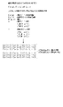
図5に示すように、各運転席ビーコン(ビーコン11、12)からの無線信号の受信信号強度をEd(m)とし、各同乗者席ビーコン(ビーコン21~23)からの無線信号の受信信号強度をEp(n)とする。そして、端末制御部51は、Ed(m)/Ep(n)を算出し、その値(比)が閾値R(m、n)以上であるか否かに基づいて、自端末5の位置を判定する。尚、mは運転席ビーコン番号であり、便宜上、D席のドアのビーコン11の運転席ビーコン番号を「1」とし、D席のP席寄りのビーコン12の運転席ビーコン番号を「2」とする(nについては上記第1の実施の形態と同様)。
そして、端末制御部51は、Ed(m)毎に、複数(本例では3つ)のEp(n)とのそれぞれの比を算出し、それらの比をそれぞれに対応する閾値R(m、n)と比較することに基づいて、自端末5の位置を判定する。詳述すると、端末制御部51は、2つのmと3つのnとの組み合わせによる次の6つの式のいずれかが成立する場合に、携帯端末5の位置が運転席であると判定し、それら6つの式がいずれも成立しない場合に、携帯端末5の位置が同乗者席であると判定する。6つの式は次の通りである。
mが「1」でnが「1」の、Ed(m=1)/Ep(n=1)≧R(m=1、n=1)
mが「1」でnが「2」の、Ed(m=1)/Ep(n=2)≧R(m=1、n=2)
mが「1」でnが「3」の、Ed(m=1)/Ep(n=3)≧R(m=1、n=3)
mが「2」でnが「1」の、Ed(m=2)/Ep(n=1)≧R(m=2、n=1)
mが「2」でnが「2」の、Ed(m=2)/Ep(n=2)≧R(m=2、n=2)
mが「2」でnが「3」の、Ed(m=2)/Ep(n=3)≧R(m=2、n=3)
運転席(D席)は第1位置(携帯端末5の位置の判定対象となるエリア)に相当し、同乗者席(P席、RL席、RR席)は第2位置に相当する。そして、Ed(m)は第1位置のビーコン11、12に由来する第1受信信号強度に相当し、Ep(n)は第2位置のビーコン21~23に由来する第2受信信号強度に相当する。端末制御部51は、第1受信信号強度Ed(m)と第2受信信号強度Ep(n)との比を算出し、その比を閾値R(m、n)と比較することに基づいて、自端末5の位置を判定していることになる。さらに言えば、端末制御部51は、第1受信信号強度Ed(m)を必ず用いて第2受信信号強度Ep(n)との比を算出していることになる。ビーコン11~12、21~23は、携帯端末5と通信する異なる位置に配置された少なくとも3つの通信部に相当し、本例では、それらのうち各ビーコン11、12が、受信信号強度の比を算出するために必須の主通信部に相当し、他のビーコン21~23が副通信部に相当する。
mが「1」でnが「2」の、Ed(m=1)/Ep(n=2)≧R(m=1、n=2)
mが「1」でnが「3」の、Ed(m=1)/Ep(n=3)≧R(m=1、n=3)
mが「2」でnが「1」の、Ed(m=2)/Ep(n=1)≧R(m=2、n=1)
mが「2」でnが「2」の、Ed(m=2)/Ep(n=2)≧R(m=2、n=2)
mが「2」でnが「3」の、Ed(m=2)/Ep(n=3)≧R(m=2、n=3)
運転席(D席)は第1位置(携帯端末5の位置の判定対象となるエリア)に相当し、同乗者席(P席、RL席、RR席)は第2位置に相当する。そして、Ed(m)は第1位置のビーコン11、12に由来する第1受信信号強度に相当し、Ep(n)は第2位置のビーコン21~23に由来する第2受信信号強度に相当する。端末制御部51は、第1受信信号強度Ed(m)と第2受信信号強度Ep(n)との比を算出し、その比を閾値R(m、n)と比較することに基づいて、自端末5の位置を判定していることになる。さらに言えば、端末制御部51は、第1受信信号強度Ed(m)を必ず用いて第2受信信号強度Ep(n)との比を算出していることになる。ビーコン11~12、21~23は、携帯端末5と通信する異なる位置に配置された少なくとも3つの通信部に相当し、本例では、それらのうち各ビーコン11、12が、受信信号強度の比を算出するために必須の主通信部に相当し、他のビーコン21~23が副通信部に相当する。
以上説明したように、第2の実施の形態の携帯端末位置判定装置によれば、以下の効果を奏することができる。
(8)携帯端末位置判定装置は、単に第1受信信号強度Ed(m)と第2受信信号強度Ep(n)とでどちらが大きいか判断するのではなく、どちらがどれだけ大きいか判断するために両者の比を算出し、その比を閾値R(m、n)と比較することに基づいて、携帯端末5の位置を判定する。したがって、携帯端末5の位置の判定精度を向上できる。
(8)携帯端末位置判定装置は、単に第1受信信号強度Ed(m)と第2受信信号強度Ep(n)とでどちらが大きいか判断するのではなく、どちらがどれだけ大きいか判断するために両者の比を算出し、その比を閾値R(m、n)と比較することに基づいて、携帯端末5の位置を判定する。したがって、携帯端末5の位置の判定精度を向上できる。
(9)携帯端末位置判定装置は、ビーコン11~12、21~23の数だけ携帯端末5との通信の通信強度(受信信号強度)を測定し、それぞれの通信強度の比を閾値R(m、n)と比較することに基づいて、携帯端末5の位置を判定する。これにより、携帯端末5の位置を精度良く判定できる。
(10)携帯端末位置判定装置は、携帯端末5と各運転席ビーコン(主通信部であるビーコン11、12)による第1受信信号強度Ed(m)を必ず用いて比を算出し、その比を閾値R(m、n)と比較することに基づいて、運転席に携帯端末5があるか否かを精度良く判定できる。
(11)携帯端末位置判定装置は、運転席ビーコン(ビーコン11、12)の数(2つ)と同乗者席ビーコン(ビーコン21~23)の数(3つ)とを掛け合わせた数(6つ)だけ、それぞれ対応する閾値R(m=1~2、n=1~3)と比較する複数の判定処理を行うことに基づいて、携帯端末5の位置を判定する。これにより、携帯端末5の位置を精度良く判定できる。
(12)走行中の運転者の携帯端末5の使用をより精度良く制限できる。
(13)同乗者が携帯端末5の使用制限をキャンセルする必要が無くなる。
(14)携帯端末位置判定装置は、車両IDを利用して、車両IDが一致するときのみ携帯端末5の位置を判定し、一致しないときは携帯端末5の位置を判定しないこととすれば、携帯端末5の位置の誤判定を防止できる。
(13)同乗者が携帯端末5の使用制限をキャンセルする必要が無くなる。
(14)携帯端末位置判定装置は、車両IDを利用して、車両IDが一致するときのみ携帯端末5の位置を判定し、一致しないときは携帯端末5の位置を判定しないこととすれば、携帯端末5の位置の誤判定を防止できる。
(第3の実施の形態)
次に、携帯端末位置判定装置の第3の実施の形態について説明する。前提となる構成は上記第2の実施の形態と同様(図4参照)である。
次に、携帯端末位置判定装置の第3の実施の形態について説明する。前提となる構成は上記第2の実施の形態と同様(図4参照)である。
次に、携帯端末位置判定装置の作用について説明する。携帯端末5の端末制御部51が実行するモード設定処理については上記第1の実施の形態と同様(図2参照)であるため説明を割愛し、端末制御部51による自端末5の位置判定ロジックについて説明する。
図6に示すように、各運転席ビーコン(ビーコン11、12)からの無線信号の受信信号強度をEd(m)とし、この第3の実施の形態では、各同乗者席ビーコン(ビーコン21~23)からの無線信号の受信信号強度のうち最大のものをEp(n)とする。そして、端末制御部51は、Ed(m)/Ep(n)を算出し、その値(比)が閾値R(m、n)以上であるか否かに基づいて、自端末5の位置を判定する。尚、mは運転席ビーコン番号であり、nは受信信号強度が最大の同乗者席ビーコン番号である。
そして、端末制御部51は、Ed(m)毎に、Ep(n)との比を算出し、それらの比をそれぞれに対応する閾値R(m、n)と比較することに基づいて、自端末5の位置を判定する。詳述すると、端末制御部51は、Ed(m=1)/Ep(n)≧R(m=1、n)、Ed(m=2)/Ep(n)≧R(m=2、n)、のいずれかが成立する場合に、携帯端末5の位置が運転席であると判定する。一方、端末制御部51は、Ed(m=1)/Ep(n)≧R(m=1、n)、Ed(m=2)/Ep(n)≧R(m=2、n)、がいずれも成立しない場合に、携帯端末5の位置が同乗者席であると判定する。
運転席(D席)は第1位置(携帯端末5の位置の判定対象となるエリア)に相当し、同乗者席(P席、RL席、RR席)は第2位置に相当する。そして、Ed(m)は第1位置のビーコン11、12に由来する第1受信信号強度に相当し、Ep(n)は第2位置のビーコン21~23に由来する最大の第2受信信号強度に相当する。端末制御部51は、第1受信信号強度Ed(m)と最大の第2受信信号強度Ep(n)との比を算出し、その比をそれに対応する閾値R(m、n)と比較することに基づいて、自端末5の位置を判定していることになる。さらに言えば、端末制御部51は、第1受信信号強度Ed(m)を必ず用いて最大の第2受信信号強度Ep(n)との比を算出していることになる。上記第2の実施の形態と同様、ビーコン11~12、21~23は、携帯端末5と通信する異なる位置に配置された少なくとも3つの通信部に相当し、本例では、それらのうち各ビーコン11、12が、受信信号強度の比を算出するために必須の主通信部に相当し、他のビーコン21~23が副通信部に相当する。また、この第3の実施の形態の端末制御部51は、主通信部以外の通信部(ビーコン21~23)における最大通信強度である第2受信信号強度Ep(n)を用いて比を算出していることになる。
ここで、最大の第2受信信号強度Ep(n)を使用することによる技術的意義について説明する。
図7に示すように、携帯端末5の位置がRR席である場合を想定する。この場合、RR席のビーコン23からの無線信号の受信信号強度が最大となるため、そのビーコン23に由来するEp(n=3)が、Ed(m=1)との比の算出に使用されるとともに、Ed(m=2)との比の算出に使用される。そして、Ed(m=1)/Ep(n=3)≧R(m=1、n=3)、Ed(m=2)/Ep(n=3)≧R(m=2、n=3)、がいずれも成立しないため、携帯端末5の位置が同乗者席であると正しく判定される。
図7に示すように、携帯端末5の位置がRR席である場合を想定する。この場合、RR席のビーコン23からの無線信号の受信信号強度が最大となるため、そのビーコン23に由来するEp(n=3)が、Ed(m=1)との比の算出に使用されるとともに、Ed(m=2)との比の算出に使用される。そして、Ed(m=1)/Ep(n=3)≧R(m=1、n=3)、Ed(m=2)/Ep(n=3)≧R(m=2、n=3)、がいずれも成立しないため、携帯端末5の位置が同乗者席であると正しく判定される。
ちなみに、本例とは異なり、P席のビーコン21に由来するEp(n=1)を、Ed(m=1)或いはEd(m=2)との比の算出に使用する例では、Ed(m=1)/Ep(n=1)≧R(m=1、n=1)、Ed(m=2)/Ep(n=1)≧R(m=2、n=1)、のいずれかが成立する可能性がある。同様に、RL席のビーコン22に由来するEp(n=2)を、Ed(m=1)或いはEd(m=2)との比の算出に使用する例では、Ed(m=1)/Ep(n=2)≧R(m=1、n=2)、Ed(m=2)/Ep(n=2)≧R(m=2、n=2)、のいずれかが成立する可能性がある。これらの例では、携帯端末5の位置が運転席であると誤判定される可能性があるが、最大の第2受信信号強度Ep(n)を使用する本例では、上記の通り正しく判定される。このように携帯端末5の位置の判定精度を向上できる点が、最大の第2受信信号強度Ep(n)を使用することによる技術的意義ということになる。
以上説明したように、第3の実施の形態の携帯端末位置判定装置によれば、上記第2の実施の形態による(8)~(14)の効果と同様の効果に加え、さらに以下の効果を奏することができる。
(15)図7を参照して、携帯端末位置判定装置は、同乗者席ビーコン(ビーコン21~23)のうち、携帯端末5から遠いビーコン21、22に由来するEp(n=1)やEp(n=2)を使用せず、携帯端末5から最も近いビーコン23に由来するEp(n=3)を使用して比を算出する。これにより、携帯端末5の位置を精度良く判定できる。
(15)図7を参照して、携帯端末位置判定装置は、同乗者席ビーコン(ビーコン21~23)のうち、携帯端末5から遠いビーコン21、22に由来するEp(n=1)やEp(n=2)を使用せず、携帯端末5から最も近いビーコン23に由来するEp(n=3)を使用して比を算出する。これにより、携帯端末5の位置を精度良く判定できる。
尚、上記各実施の形態は、次のように変更して具体化することも可能である。
・上記各実施の形態において、P席のビーコン21、RL席のビーコン22、RR席のビーコン23、のいずれか1つ又は2つを割愛してもよい。
・上記各実施の形態において、P席のビーコン21、RL席のビーコン22、RR席のビーコン23、のいずれか1つ又は2つを割愛してもよい。
・上記第2又は第3の実施の形態において、運転席ビーコンの数を3つ以上としてもよいし、同乗者席ビーコンの数を4つ以上としてもよい。
・上記各実施の形態において、運転席ビーコンの設置場所を運転席内で変更してもよいし、同乗者席ビーコンの設置場所を同乗者席内で変更してもよい。尚、運転席ビーコン及び同乗者席ビーコンの設置場所に応じて、適切な閾値R(n)或いは閾値R(m、n)を設定することで、携帯端末5の位置の判定精度を向上できる。
・上記各実施の形態において、運転席ビーコンの設置場所を運転席内で変更してもよいし、同乗者席ビーコンの設置場所を同乗者席内で変更してもよい。尚、運転席ビーコン及び同乗者席ビーコンの設置場所に応じて、適切な閾値R(n)或いは閾値R(m、n)を設定することで、携帯端末5の位置の判定精度を向上できる。
・上記各実施の形態において、いずれか1つの式が成立する場合に携帯端末5の位置が運転席であると判定する代わりに、2つ以上の式が成立する場合に携帯端末5の位置が運転席であると判定し、そうでない場合に携帯端末5の位置が同乗者席であると判定してもよい。
・上記各実施の形態において、第1受信信号強度の平均値と第2受信信号強度の平均値との比を算出し、その比を閾値と比較することに基づいて、携帯端末5の位置を判定してもよい。尚、上記第1の実施の形態において、唯一の第1受信信号強度と第2受信信号強度の平均値との比を算出し、その比を閾値と比較することに基づいて、携帯端末5の位置を判定してもよい。
・上記第2及び第3の実施の形態において、最大の第1受信信号強度と最大の第2受信信号強度との比を算出し、その比を閾値と比較することに基づいて、携帯端末5の位置を判定してもよい。尚、上記第1の実施の形態において、唯一の第1受信信号強度と最大の第2受信信号強度との比を算出し、その比を閾値と比較することに基づいて、携帯端末5の位置を判定してもよい。
・上記各実施の形態において、携帯端末5の位置判定を端末制御部51が行う代わりに、車載コントローラ31が携帯端末5の位置判定を行い、その車載コントローラ31からのモード設定信号を受けて携帯端末5が運転者モードに設定されたり、運転者モードが解除されたりしてもよい。この場合、ビーコン11~12、21~23からの無線信号の受信信号強度の測定結果が携帯端末5から送信され、その測定結果が車両1又は2で受信され、当該測定結果に基づいて、車載コントローラ31が携帯端末5の位置を判定する。車載コントローラ31が位置判定手段に相当する。
・上記各実施の形態において、複数のビーコン11~12、21~23からの無線信号を携帯端末5で受信する代わりに、携帯端末5からの無線信号を複数の受信機(ビーコンに代えて車両1又は2に設置)で受信することに基づいて、携帯端末5の位置が受信機によって規定される位置のうちいずれにあるかを携帯端末5又は車両1(或いは2)で判定してもよい。この場合、ビーコンに代えて車両1又は2に設置されるそれぞれの受信機が、携帯端末5と通信する異なる位置に配置された少なくとも2つの通信部に相当し、それらのうちビーコン11~12に代わる第1位置の受信機が、受信信号強度の比を算出するために必須の主通信部に相当する。また、第1位置の受信機が第1受信信号強度を測定するとともに、第2位置の受信機が第2受信信号強度を測定し、それぞれの受信機が、携帯端末5との通信の通信強度(受信信号強度)を測定する通信強度測定手段に相当する。
そして、携帯端末5の位置を車両1又は2で判定する構成では、車載コントローラ31が第1受信信号強度と第2受信信号強度との比を算出し、その比を閾値と比較することに基づいて、携帯端末5の位置を判定する。従って、車載コントローラ31が位置判定手段に相当する。
一方、携帯端末5で自端末5の位置を判定する構成では、第1受信信号強度及び第2受信信号強度の測定結果が車両1又は2から送信され、その測定結果が携帯端末5で受信され、当該測定結果に基づいて、端末制御部51が携帯端末5の位置を判定する。従って、端末制御部51が位置判定手段に相当する。
・本発明に係る携帯端末位置判定装置を自家用車の他、路線バス或いは鉄道車両等の公共交通機関に適用してもよい。路線バス或いは鉄道車両の運転士による携帯端末5の使用(例えば走行中に限らず停車中を含む)を制限できる他、乗客による車内での携帯端末5の使用(通話等)を制限することもできる。航空機に適用すればコックピット内を含め機内での携帯端末5の使用(離着陸時等)を制限できる。尚、乗り物に限らず、図書館等の公共施設に適用してもよい。施設内での携帯端末5の使用(通話等)を制限できることになる。
Claims (6)
- 携帯端末と通信する異なる位置に配置された少なくとも2つの通信部と、
前記携帯端末と各前記通信部による通信の通信強度を測定する通信強度測定手段と、
前記通信強度測定手段により測定された2つの通信強度の比を対応する閾値と比較することで前記携帯端末の位置を判定する位置判定手段とを有する、
携帯端末位置判定装置。 - 前記少なくとも2つの通信部は少なくとも3つの通信部を有する、
請求項1に記載の携帯端末位置判定装置。 - 前記通信部の少なくとも1つは、前記携帯端末の位置の判定対象となるエリアに配置されており、前記通信強度の比を算出するために必須の主通信部である、
請求項1又は2に記載の携帯端末位置判定装置。 - 前記位置判定手段は、前記主通信部以外の通信部における最大通信強度を用いて比を算出する、
請求項3に記載の携帯端末位置判定装置。 - 第1位置に配置され、携帯端末と通信する主通信部と、
前記第1位置とは異なる第2位置に配置され、前記携帯端末と通信する副通信部と、
前記主通信部と前記携帯端末との通信の強度を第1通信強度として測定し、前記副通信部と前記携帯端末との通信の強度を第2通信強度として測定する通信強度測定手段と、
前記第1通信強度と前記第2通信強度の比を、前記主通信部と前記副通信部とに関連付けられた閾値と比較することで前記携帯端末の位置を判定する位置判定手段とを有する、
携帯端末位置判定装置。 - 前記主通信部は、前記第1位置に配置される少なくとも1つの主通信部のうちの1つであり、
前記副通信部は、前記第2位置に配置される少なくとも2つの副通信部のうちの1つであり、
前記通信強度測定手段は、前記少なくとも1つの主通信部と前記携帯端末との通信の強度を少なくとも1つの第1通信強度として測定するとともに、前記少なくとも2つの副通信部と前記携帯端末との通信の強度を少なくとも2つの第2通信強度として測定し、
前記位置判定手段は、各前記第1通信強度と各前記第2通信強度の比を、対応する前記主通信部と対応する前記副通信部とに関連付けられた対応する閾値と比較することで前記携帯端末の位置を判定する、
請求項5に記載の携帯端末位置判定装置。
Applications Claiming Priority (2)
| Application Number | Priority Date | Filing Date | Title |
|---|---|---|---|
| JP2018-105003 | 2018-05-31 | ||
| JP2018105003A JP2019211240A (ja) | 2018-05-31 | 2018-05-31 | 携帯端末位置判定装置 |
Publications (1)
| Publication Number | Publication Date |
|---|---|
| WO2019230409A1 true WO2019230409A1 (ja) | 2019-12-05 |
Family
ID=68697987
Family Applications (1)
| Application Number | Title | Priority Date | Filing Date |
|---|---|---|---|
| PCT/JP2019/019431 Ceased WO2019230409A1 (ja) | 2018-05-31 | 2019-05-16 | 携帯端末位置判定装置 |
Country Status (2)
| Country | Link |
|---|---|
| JP (1) | JP2019211240A (ja) |
| WO (1) | WO2019230409A1 (ja) |
Cited By (1)
| Publication number | Priority date | Publication date | Assignee | Title |
|---|---|---|---|---|
| CN116804732A (zh) * | 2022-03-25 | 2023-09-26 | 株式会社东海理化电机制作所 | 判定装置、判定方法和判定系统 |
Families Citing this family (1)
| Publication number | Priority date | Publication date | Assignee | Title |
|---|---|---|---|---|
| JP7736740B2 (ja) * | 2023-05-23 | 2025-09-09 | 矢崎総業株式会社 | 制御システム |
Citations (7)
| Publication number | Priority date | Publication date | Assignee | Title |
|---|---|---|---|---|
| JPH10256979A (ja) * | 1997-03-13 | 1998-09-25 | Nippon Soken Inc | 車両用通信装置 |
| JP2003248045A (ja) * | 2002-02-22 | 2003-09-05 | Alpine Electronics Inc | 車室内乗員位置検出装置および車載機器制御システム |
| JP2005328116A (ja) * | 2004-05-12 | 2005-11-24 | Alpine Electronics Inc | 車載システム |
| JP2009281793A (ja) * | 2008-05-20 | 2009-12-03 | Brother Ind Ltd | 移動局測位システム |
| US20110105097A1 (en) * | 2009-10-31 | 2011-05-05 | Saied Tadayon | Controlling Mobile Device Functions |
| US20160248905A1 (en) * | 2014-01-06 | 2016-08-25 | Ford Global Technologies, Llc | Apparatus and method for in-vehicle location of a mobile device |
| WO2017081743A1 (ja) * | 2015-11-10 | 2017-05-18 | 三菱電機株式会社 | 車載機器 |
-
2018
- 2018-05-31 JP JP2018105003A patent/JP2019211240A/ja active Pending
-
2019
- 2019-05-16 WO PCT/JP2019/019431 patent/WO2019230409A1/ja not_active Ceased
Patent Citations (7)
| Publication number | Priority date | Publication date | Assignee | Title |
|---|---|---|---|---|
| JPH10256979A (ja) * | 1997-03-13 | 1998-09-25 | Nippon Soken Inc | 車両用通信装置 |
| JP2003248045A (ja) * | 2002-02-22 | 2003-09-05 | Alpine Electronics Inc | 車室内乗員位置検出装置および車載機器制御システム |
| JP2005328116A (ja) * | 2004-05-12 | 2005-11-24 | Alpine Electronics Inc | 車載システム |
| JP2009281793A (ja) * | 2008-05-20 | 2009-12-03 | Brother Ind Ltd | 移動局測位システム |
| US20110105097A1 (en) * | 2009-10-31 | 2011-05-05 | Saied Tadayon | Controlling Mobile Device Functions |
| US20160248905A1 (en) * | 2014-01-06 | 2016-08-25 | Ford Global Technologies, Llc | Apparatus and method for in-vehicle location of a mobile device |
| WO2017081743A1 (ja) * | 2015-11-10 | 2017-05-18 | 三菱電機株式会社 | 車載機器 |
Cited By (1)
| Publication number | Priority date | Publication date | Assignee | Title |
|---|---|---|---|---|
| CN116804732A (zh) * | 2022-03-25 | 2023-09-26 | 株式会社东海理化电机制作所 | 判定装置、判定方法和判定系统 |
Also Published As
| Publication number | Publication date |
|---|---|
| JP2019211240A (ja) | 2019-12-12 |
Similar Documents
| Publication | Publication Date | Title |
|---|---|---|
| US12222432B2 (en) | Method and apparatus for vehicle occupant location detection | |
| JP6359359B2 (ja) | 電子キー装置 | |
| US10139481B2 (en) | Radio communication system and distance measuring method | |
| US20210011143A1 (en) | Distance measurement system | |
| US7482921B2 (en) | Method and device for localizing transponders | |
| KR102218144B1 (ko) | 차량 인근에 배치된 원격 송신기의 위치를 결정하기 위한 방법 | |
| US9967717B2 (en) | Efficient tracking of personal device locations | |
| JP7234170B2 (ja) | 測距装置及び測距方法 | |
| US10245903B2 (en) | Communication device mounting position determination system and determination apparatus | |
| KR102276495B1 (ko) | 차량의 기능을 활성화시키기 위한 방법 | |
| US11740318B2 (en) | Tire pressure monitoring system and tire pressure monitoring method | |
| JP2020034444A (ja) | 携帯機位置推定システム | |
| WO2018120830A1 (zh) | 基于ibeacon的车内定位装置、方法和车内设备控制系统 | |
| JP2019085734A (ja) | 車両用電子キーシステム | |
| JP2019211240A (ja) | 携帯端末位置判定装置 | |
| JP7206926B2 (ja) | 乗員位置推定システム | |
| CN104471349B (zh) | 车载器 | |
| US11926281B2 (en) | Calculation means, arrangement and method for determining the position of an authentication means for a vehicle | |
| WO2022043821A1 (ja) | 解錠システムおよび該解錠システムの制御方法、制御装置および該制御装置の制御方 | |
| US20160140843A1 (en) | Vehicle traveling support communication apparatus and communication system | |
| CN110876131A (zh) | 移动终端设备相对于车辆的定位 | |
| US10999707B2 (en) | Position determination system and position determination method | |
| JP2017161430A (ja) | 他車両の位置検出装置 | |
| WO2021106352A1 (ja) | 車両用システム、車載装置、及び端末位置特定方法 | |
| JPH11211768A (ja) | 電界強度送信装置、電界強度受信装置及び電界強度解析システム並びに電界強度解析方法 |
Legal Events
| Date | Code | Title | Description |
|---|---|---|---|
| 121 | Ep: the epo has been informed by wipo that ep was designated in this application |
Ref document number: 19810249 Country of ref document: EP Kind code of ref document: A1 |
|
| NENP | Non-entry into the national phase |
Ref country code: DE |
|
| 122 | Ep: pct application non-entry in european phase |
Ref document number: 19810249 Country of ref document: EP Kind code of ref document: A1 |