WO2019220786A1 - 蒸気タービンプラント、及びその冷却方法 - Google Patents
蒸気タービンプラント、及びその冷却方法 Download PDFInfo
- Publication number
- WO2019220786A1 WO2019220786A1 PCT/JP2019/013339 JP2019013339W WO2019220786A1 WO 2019220786 A1 WO2019220786 A1 WO 2019220786A1 JP 2019013339 W JP2019013339 W JP 2019013339W WO 2019220786 A1 WO2019220786 A1 WO 2019220786A1
- Authority
- WO
- WIPO (PCT)
- Prior art keywords
- steam
- temperature
- boiler
- valve
- low
- Prior art date
- Legal status (The legal status is an assumption and is not a legal conclusion. Google has not performed a legal analysis and makes no representation as to the accuracy of the status listed.)
- Ceased
Links
Images




Classifications
-
- F—MECHANICAL ENGINEERING; LIGHTING; HEATING; WEAPONS; BLASTING
- F01—MACHINES OR ENGINES IN GENERAL; ENGINE PLANTS IN GENERAL; STEAM ENGINES
- F01D—NON-POSITIVE DISPLACEMENT MACHINES OR ENGINES, e.g. STEAM TURBINES
- F01D25/00—Component parts, details, or accessories, not provided for in, or of interest apart from, other groups
- F01D25/08—Cooling; Heating; Heat-insulation
- F01D25/12—Cooling
-
- F—MECHANICAL ENGINEERING; LIGHTING; HEATING; WEAPONS; BLASTING
- F01—MACHINES OR ENGINES IN GENERAL; ENGINE PLANTS IN GENERAL; STEAM ENGINES
- F01D—NON-POSITIVE DISPLACEMENT MACHINES OR ENGINES, e.g. STEAM TURBINES
- F01D17/00—Regulating or controlling by varying flow
- F01D17/10—Final actuators
- F01D17/12—Final actuators arranged in stator parts
- F01D17/14—Final actuators arranged in stator parts varying effective cross-sectional area of nozzles or guide conduits
- F01D17/141—Final actuators arranged in stator parts varying effective cross-sectional area of nozzles or guide conduits by means of shiftable members or valves obturating part of the flow path
- F01D17/145—Final actuators arranged in stator parts varying effective cross-sectional area of nozzles or guide conduits by means of shiftable members or valves obturating part of the flow path by means of valves, e.g. for steam turbines
-
- F—MECHANICAL ENGINEERING; LIGHTING; HEATING; WEAPONS; BLASTING
- F01—MACHINES OR ENGINES IN GENERAL; ENGINE PLANTS IN GENERAL; STEAM ENGINES
- F01D—NON-POSITIVE DISPLACEMENT MACHINES OR ENGINES, e.g. STEAM TURBINES
- F01D15/00—Adaptations of machines or engines for special use; Combinations of engines with devices driven thereby
-
- F—MECHANICAL ENGINEERING; LIGHTING; HEATING; WEAPONS; BLASTING
- F01—MACHINES OR ENGINES IN GENERAL; ENGINE PLANTS IN GENERAL; STEAM ENGINES
- F01D—NON-POSITIVE DISPLACEMENT MACHINES OR ENGINES, e.g. STEAM TURBINES
- F01D15/00—Adaptations of machines or engines for special use; Combinations of engines with devices driven thereby
- F01D15/10—Adaptations for driving, or combinations with, electric generators
-
- F—MECHANICAL ENGINEERING; LIGHTING; HEATING; WEAPONS; BLASTING
- F01—MACHINES OR ENGINES IN GENERAL; ENGINE PLANTS IN GENERAL; STEAM ENGINES
- F01D—NON-POSITIVE DISPLACEMENT MACHINES OR ENGINES, e.g. STEAM TURBINES
- F01D17/00—Regulating or controlling by varying flow
- F01D17/10—Final actuators
-
- F—MECHANICAL ENGINEERING; LIGHTING; HEATING; WEAPONS; BLASTING
- F01—MACHINES OR ENGINES IN GENERAL; ENGINE PLANTS IN GENERAL; STEAM ENGINES
- F01D—NON-POSITIVE DISPLACEMENT MACHINES OR ENGINES, e.g. STEAM TURBINES
- F01D19/00—Starting of machines or engines; Regulating, controlling, or safety means in connection therewith
-
- F—MECHANICAL ENGINEERING; LIGHTING; HEATING; WEAPONS; BLASTING
- F01—MACHINES OR ENGINES IN GENERAL; ENGINE PLANTS IN GENERAL; STEAM ENGINES
- F01D—NON-POSITIVE DISPLACEMENT MACHINES OR ENGINES, e.g. STEAM TURBINES
- F01D21/00—Shutting-down of machines or engines, e.g. in emergency; Regulating, controlling, or safety means not otherwise provided for
- F01D21/003—Arrangements for testing or measuring
-
- F—MECHANICAL ENGINEERING; LIGHTING; HEATING; WEAPONS; BLASTING
- F01—MACHINES OR ENGINES IN GENERAL; ENGINE PLANTS IN GENERAL; STEAM ENGINES
- F01K—STEAM ENGINE PLANTS; STEAM ACCUMULATORS; ENGINE PLANTS NOT OTHERWISE PROVIDED FOR; ENGINES USING SPECIAL WORKING FLUIDS OR CYCLES
- F01K11/00—Plants characterised by the engines being structurally combined with boilers or condensers
- F01K11/02—Plants characterised by the engines being structurally combined with boilers or condensers the engines being turbines
-
- F—MECHANICAL ENGINEERING; LIGHTING; HEATING; WEAPONS; BLASTING
- F01—MACHINES OR ENGINES IN GENERAL; ENGINE PLANTS IN GENERAL; STEAM ENGINES
- F01K—STEAM ENGINE PLANTS; STEAM ACCUMULATORS; ENGINE PLANTS NOT OTHERWISE PROVIDED FOR; ENGINES USING SPECIAL WORKING FLUIDS OR CYCLES
- F01K13/00—General layout or general methods of operation of complete plants
- F01K13/003—Arrangements for measuring or testing
-
- F—MECHANICAL ENGINEERING; LIGHTING; HEATING; WEAPONS; BLASTING
- F01—MACHINES OR ENGINES IN GENERAL; ENGINE PLANTS IN GENERAL; STEAM ENGINES
- F01K—STEAM ENGINE PLANTS; STEAM ACCUMULATORS; ENGINE PLANTS NOT OTHERWISE PROVIDED FOR; ENGINES USING SPECIAL WORKING FLUIDS OR CYCLES
- F01K13/00—General layout or general methods of operation of complete plants
- F01K13/02—Controlling, e.g. stopping or starting
-
- F—MECHANICAL ENGINEERING; LIGHTING; HEATING; WEAPONS; BLASTING
- F01—MACHINES OR ENGINES IN GENERAL; ENGINE PLANTS IN GENERAL; STEAM ENGINES
- F01K—STEAM ENGINE PLANTS; STEAM ACCUMULATORS; ENGINE PLANTS NOT OTHERWISE PROVIDED FOR; ENGINES USING SPECIAL WORKING FLUIDS OR CYCLES
- F01K13/00—General layout or general methods of operation of complete plants
- F01K13/02—Controlling, e.g. stopping or starting
- F01K13/025—Cooling the interior by injection during idling or stand-by
-
- F—MECHANICAL ENGINEERING; LIGHTING; HEATING; WEAPONS; BLASTING
- F01—MACHINES OR ENGINES IN GENERAL; ENGINE PLANTS IN GENERAL; STEAM ENGINES
- F01K—STEAM ENGINE PLANTS; STEAM ACCUMULATORS; ENGINE PLANTS NOT OTHERWISE PROVIDED FOR; ENGINES USING SPECIAL WORKING FLUIDS OR CYCLES
- F01K23/00—Plants characterised by more than one engine delivering power external to the plant, the engines being driven by different fluids
- F01K23/02—Plants characterised by more than one engine delivering power external to the plant, the engines being driven by different fluids the engine cycles being thermally coupled
- F01K23/06—Plants characterised by more than one engine delivering power external to the plant, the engines being driven by different fluids the engine cycles being thermally coupled combustion heat from one cycle heating the fluid in another cycle
- F01K23/10—Plants characterised by more than one engine delivering power external to the plant, the engines being driven by different fluids the engine cycles being thermally coupled combustion heat from one cycle heating the fluid in another cycle with exhaust fluid of one cycle heating the fluid in another cycle
-
- F—MECHANICAL ENGINEERING; LIGHTING; HEATING; WEAPONS; BLASTING
- F01—MACHINES OR ENGINES IN GENERAL; ENGINE PLANTS IN GENERAL; STEAM ENGINES
- F01K—STEAM ENGINE PLANTS; STEAM ACCUMULATORS; ENGINE PLANTS NOT OTHERWISE PROVIDED FOR; ENGINES USING SPECIAL WORKING FLUIDS OR CYCLES
- F01K23/00—Plants characterised by more than one engine delivering power external to the plant, the engines being driven by different fluids
- F01K23/02—Plants characterised by more than one engine delivering power external to the plant, the engines being driven by different fluids the engine cycles being thermally coupled
- F01K23/06—Plants characterised by more than one engine delivering power external to the plant, the engines being driven by different fluids the engine cycles being thermally coupled combustion heat from one cycle heating the fluid in another cycle
- F01K23/10—Plants characterised by more than one engine delivering power external to the plant, the engines being driven by different fluids the engine cycles being thermally coupled combustion heat from one cycle heating the fluid in another cycle with exhaust fluid of one cycle heating the fluid in another cycle
- F01K23/101—Regulating means specially adapted therefor
-
- F—MECHANICAL ENGINEERING; LIGHTING; HEATING; WEAPONS; BLASTING
- F02—COMBUSTION ENGINES; HOT-GAS OR COMBUSTION-PRODUCT ENGINE PLANTS
- F02C—GAS-TURBINE PLANTS; AIR INTAKES FOR JET-PROPULSION PLANTS; CONTROLLING FUEL SUPPLY IN AIR-BREATHING JET-PROPULSION PLANTS
- F02C6/00—Plural gas-turbine plants; Combinations of gas-turbine plants with other apparatus; Adaptations of gas-turbine plants for special use
-
- F—MECHANICAL ENGINEERING; LIGHTING; HEATING; WEAPONS; BLASTING
- F02—COMBUSTION ENGINES; HOT-GAS OR COMBUSTION-PRODUCT ENGINE PLANTS
- F02C—GAS-TURBINE PLANTS; AIR INTAKES FOR JET-PROPULSION PLANTS; CONTROLLING FUEL SUPPLY IN AIR-BREATHING JET-PROPULSION PLANTS
- F02C9/00—Controlling gas-turbine plants; Controlling fuel supply in air- breathing jet-propulsion plants
- F02C9/26—Control of fuel supply
- F02C9/28—Regulating systems responsive to plant or ambient parameters, e.g. temperature, pressure, rotor speed
-
- F—MECHANICAL ENGINEERING; LIGHTING; HEATING; WEAPONS; BLASTING
- F22—STEAM GENERATION
- F22B—METHODS OF STEAM GENERATION; STEAM BOILERS
- F22B1/00—Methods of steam generation characterised by form of heating method
- F22B1/02—Methods of steam generation characterised by form of heating method by exploitation of the heat content of hot heat carriers
- F22B1/18—Methods of steam generation characterised by form of heating method by exploitation of the heat content of hot heat carriers the heat carrier being a hot gas, e.g. waste gas such as exhaust gas of internal-combustion engines
- F22B1/1807—Methods of steam generation characterised by form of heating method by exploitation of the heat content of hot heat carriers the heat carrier being a hot gas, e.g. waste gas such as exhaust gas of internal-combustion engines using the exhaust gases of combustion engines
- F22B1/1815—Methods of steam generation characterised by form of heating method by exploitation of the heat content of hot heat carriers the heat carrier being a hot gas, e.g. waste gas such as exhaust gas of internal-combustion engines using the exhaust gases of combustion engines using the exhaust gases of gas-turbines
-
- F—MECHANICAL ENGINEERING; LIGHTING; HEATING; WEAPONS; BLASTING
- F22—STEAM GENERATION
- F22B—METHODS OF STEAM GENERATION; STEAM BOILERS
- F22B37/00—Component parts or details of steam boilers
- F22B37/02—Component parts or details of steam boilers applicable to more than one kind or type of steam boiler
- F22B37/38—Determining or indicating operating conditions in steam boilers, e.g. monitoring direction or rate of water flow through water tubes
-
- F—MECHANICAL ENGINEERING; LIGHTING; HEATING; WEAPONS; BLASTING
- F05—INDEXING SCHEMES RELATING TO ENGINES OR PUMPS IN VARIOUS SUBCLASSES OF CLASSES F01-F04
- F05D—INDEXING SCHEME FOR ASPECTS RELATING TO NON-POSITIVE-DISPLACEMENT MACHINES OR ENGINES, GAS-TURBINES OR JET-PROPULSION PLANTS
- F05D2220/00—Application
- F05D2220/30—Application in turbines
- F05D2220/31—Application in turbines in steam turbines
-
- F—MECHANICAL ENGINEERING; LIGHTING; HEATING; WEAPONS; BLASTING
- F05—INDEXING SCHEMES RELATING TO ENGINES OR PUMPS IN VARIOUS SUBCLASSES OF CLASSES F01-F04
- F05D—INDEXING SCHEME FOR ASPECTS RELATING TO NON-POSITIVE-DISPLACEMENT MACHINES OR ENGINES, GAS-TURBINES OR JET-PROPULSION PLANTS
- F05D2220/00—Application
- F05D2220/70—Application in combination with
- F05D2220/72—Application in combination with a steam turbine
-
- F—MECHANICAL ENGINEERING; LIGHTING; HEATING; WEAPONS; BLASTING
- F05—INDEXING SCHEMES RELATING TO ENGINES OR PUMPS IN VARIOUS SUBCLASSES OF CLASSES F01-F04
- F05D—INDEXING SCHEME FOR ASPECTS RELATING TO NON-POSITIVE-DISPLACEMENT MACHINES OR ENGINES, GAS-TURBINES OR JET-PROPULSION PLANTS
- F05D2220/00—Application
- F05D2220/70—Application in combination with
- F05D2220/74—Application in combination with a gas turbine
-
- F—MECHANICAL ENGINEERING; LIGHTING; HEATING; WEAPONS; BLASTING
- F05—INDEXING SCHEMES RELATING TO ENGINES OR PUMPS IN VARIOUS SUBCLASSES OF CLASSES F01-F04
- F05D—INDEXING SCHEME FOR ASPECTS RELATING TO NON-POSITIVE-DISPLACEMENT MACHINES OR ENGINES, GAS-TURBINES OR JET-PROPULSION PLANTS
- F05D2260/00—Function
- F05D2260/20—Heat transfer, e.g. cooling
-
- F—MECHANICAL ENGINEERING; LIGHTING; HEATING; WEAPONS; BLASTING
- F05—INDEXING SCHEMES RELATING TO ENGINES OR PUMPS IN VARIOUS SUBCLASSES OF CLASSES F01-F04
- F05D—INDEXING SCHEME FOR ASPECTS RELATING TO NON-POSITIVE-DISPLACEMENT MACHINES OR ENGINES, GAS-TURBINES OR JET-PROPULSION PLANTS
- F05D2270/00—Control
- F05D2270/30—Control parameters, e.g. input parameters
- F05D2270/303—Temperature
-
- Y—GENERAL TAGGING OF NEW TECHNOLOGICAL DEVELOPMENTS; GENERAL TAGGING OF CROSS-SECTIONAL TECHNOLOGIES SPANNING OVER SEVERAL SECTIONS OF THE IPC; TECHNICAL SUBJECTS COVERED BY FORMER USPC CROSS-REFERENCE ART COLLECTIONS [XRACs] AND DIGESTS
- Y02—TECHNOLOGIES OR APPLICATIONS FOR MITIGATION OR ADAPTATION AGAINST CLIMATE CHANGE
- Y02E—REDUCTION OF GREENHOUSE GAS [GHG] EMISSIONS, RELATED TO ENERGY GENERATION, TRANSMISSION OR DISTRIBUTION
- Y02E20/00—Combustion technologies with mitigation potential
- Y02E20/16—Combined cycle power plant [CCPP], or combined cycle gas turbine [CCGT]
Definitions
- the present invention relates to a steam turbine plant including a boiler and a steam turbine driven by steam from the boiler, and a cooling method thereof.
- the present application claims priority based on Japanese Patent Application No. 2018-093301 filed in Japan on May 14, 2018, the contents of which are incorporated herein by reference.
- the first method is a method in which after the steam turbine is stopped, cooling air is sent into the steam turbine and the steam turbine is forcibly cooled with the cooling air.
- the second method is the method described in Patent Document 1 below.
- this second method in the process of stopping the steam turbine, while increasing the pressure of the steam before it reaches the regulator from the boiler, the temperature of the steam flowing into the steam turbine is lowered by reducing the opening of the regulator. The steam turbine is cooled with this steam.
- Patent Document 1 it is proposed that after the steam turbine is stopped, natural cooling or forced cooling with cooling air is performed to further reduce the temperature of the steam turbine.
- the steam turbine cannot be forcibly cooled until the boiler cooling ends after the fuel supply is turned off, and the cooling end of the steam turbine is delayed. There is a point.
- an object of the present invention is to provide a technique capable of accelerating the completion of cooling of the steam turbine.
- a boiler that generates steam
- a fuel valve that adjusts the flow rate of fuel for generating the steam
- a low-temperature steam generation source that generates low-temperature steam independently of the boiler
- a steam that is driven from the boiler
- a steam turbine a main steam line that guides steam generated in the boiler to a steam inlet of the steam turbine, and a main steam control valve that is provided in the main steam line and adjusts a flow rate of steam flowing from the boiler into the steam turbine
- a low-temperature steam line connected to the low-temperature steam generation source for guiding the low-temperature steam from the low-temperature steam generation source to a position closer to the steam turbine than the main steam control valve in the main steam line, and the low temperature
- a low-temperature steam valve provided in the steam line for adjusting a flow rate of the low-temperature steam flowing through the low-temperature steam line
- a control device sends an opening instruction to the low temperature steam valve after sending
- the steam turbine can be cooled with low-temperature steam after the fuel supply is cut off during the shutdown process of the steam turbine plant. For this reason, in this aspect, the cooling of the steam turbine can be started before the inside of the condenser for returning the steam from the steam turbine to water is broken in vacuum.
- the blades on the upstream side of the blades on the downstream side of the steam flow are exposed to high-temperature steam, and the blades on the upstream side become hotter.
- wing on an upstream side can be efficiently cooled by putting low temperature steam into a steam turbine from the steam inlet of a steam turbine like this aspect.
- the low-temperature steam generation source includes a second boiler that generates steam independently of the first boiler that is the boiler, and a temperature of steam from the second boiler is reduced. And a temperature reducer that generates the low-temperature steam.
- the control device sends an open instruction to the low-temperature steam valve and then satisfies the predetermined condition when the low-temperature steam is supplied to the temperature reducer.
- the temperature may be further reduced.
- the thermal shock to the steam turbine can be suppressed and the steam turbine can be efficiently cooled.
- the low-temperature steam and the low-temperature steam drain in the low-temperature steam line are connected to the low-temperature steam generation source side of the low-temperature steam valve in the low-temperature steam line.
- a drain valve provided in the drain discharge line.
- the control device sends an opening instruction to the fuel valve, sends an opening instruction to the drain valve, and closes the drain valve after a predetermined time has passed since the opening instruction was sent to the drain valve. An instruction is sent and an opening instruction is sent to the low temperature steam valve.
- the low temperature steam line can be warmed with the low temperature steam before the low temperature steam is supplied to the steam turbine. For this reason, in this aspect, at the time of starting supply of low-temperature steam to the steam turbine, it is possible to suppress that the low-temperature steam partially liquefies in the process of passing through the low-temperature steam line. That is, in this aspect, when the supply of the low temperature steam to the steam turbine is started, the amount of drain of the low temperature steam flowing into the steam turbine can be suppressed.
- the main steam line branches off from a position closer to the boiler than the main steam control valve, and steam from the boiler is fed into the main steam line in the main steam line.
- a pressure detector for detecting the pressure at the position.
- the control device sends a closing instruction to the main steam control valve along with transmission of a closing instruction to the fuel valve, and sends an opening instruction to the surplus steam valve, which is detected by the pressure detector. When the pressure falls below a predetermined pressure, an opening instruction is sent to the low temperature steam valve.
- the steam from the boiler after the fuel supply is cut off is supplied to the steam turbine, and the steam turbine is cooled by this steam.
- the temperature of the steam generated from the boiler hardly changes. For this reason, in this aspect, the thermal shock applied to the steam turbine can be minimized before and after the fuel supply is cut off.
- a pressure detector that detects a pressure at a position closer to the boiler than the main steam control valve in the main steam line may be provided.
- the control device sends a fine opening instruction indicating that the valve opening is reduced to the main steam control valve in accordance with transmission of the closing instruction to the fuel valve, and the pressure detected by the pressure detector.
- an opening instruction is sent to the low temperature steam valve.
- the steam from the boiler after the fuel supply is cut off is supplied to the steam turbine, and the steam turbine is cooled with this steam. For this reason, also in this aspect, it is possible to minimize the thermal shock applied to the steam turbine immediately before the fuel supply is cut off.
- a condenser for returning the steam from the steam turbine to water, a water supply line for guiding water in the condenser to the boiler, and the water supply line are provided.
- a boiler water discharge valve that is provided in the boiler water discharge line and adjusts a flow rate of a fluid flowing through the boiler water discharge line.
- the control device sends a closing instruction to the fuel valve, and then sends an opening instruction to the boiler water discharge valve in a state where the pump is continuously driven.
- the boiler water discharge line may be connected to the condenser.
- the water supplied to the boiler from the condenser returns to the condenser via the boiler water discharge line. Therefore, in this aspect, the water in the condenser can be used effectively.
- control device is configured so that at least a part of a time zone in which the low-temperature steam valve is open overlaps a time zone in which the boiler water discharge valve is open.
- An opening instruction may be sent to the boiler water discharge valve.
- a steam turbine cooling process for supplying low-temperature steam to the steam turbine to cool the steam turbine and a boiler cooling process for supplying water from the condenser to the boiler to cool the boiler are executed in parallel. Will do. For this reason, in this aspect, the timing which both a boiler cooling process and a steam turbine cooling process complete can be advanced.
- the steam turbine may include a temperature detector that detects a temperature at a location where the steam from the boiler contacts. In this case, when the temperature detected by the temperature detector is equal to or lower than a predetermined temperature, the control device sends a close instruction to the low-temperature steam valve.
- the condenser comprising the condenser, a temperature detector for detecting a temperature at a location where the steam from the boiler is in contact with the steam turbine, and for cooling the steam turbine Cooling air supply device that sends cooling air into the steam turbine, and cooling that is connected to the cooling air supply device and guides the cooling air to a position closer to the steam turbine side than the main steam control valve in the main steam line An air line.
- the control device determines that the cooling of the boiler is completed before the temperature detected by the temperature detector becomes equal to or lower than a predetermined temperature
- the control device sends a close instruction to the low-temperature steam valve. Later, a supply instruction is sent to the cooling air supply machine, and if it is determined that the temperature detected by the temperature detector is equal to or lower than a predetermined temperature before the cooling of the boiler is completed, the low temperature steam valve is instructed to close. Send.
- a gas turbine that is driven by burning fuel may be provided.
- the boiler is an exhaust heat recovery boiler that generates steam by the heat of the combustion gas exhausted from the gas turbine.
- the fuel valve is a valve that adjusts a flow rate of fuel supplied to the gas turbine.
- a motor for rotating the gas turbine rotor of the gas turbine may be provided.
- the control device has sent a close instruction to the fuel valve so as to perform a spin operation for rotating the gas turbine rotor at a rotational speed lower than a rated rotational speed of the gas turbine
- a spin operation instruction is sent to the motor at a timing at which at least a part of the time zone in which the low-temperature steam valve is open overlaps the execution time zone of the spin operation.
- the gas turbine can be cooled.
- a method for cooling a steam turbine plant for solving the above problems is as follows.
- a boiler that generates steam; a steam turbine that is driven by steam from the boiler; a main steam line that guides the steam generated in the boiler to a steam inlet of the steam turbine; and
- a steam turbine plant cooling method comprising: a main steam control valve that adjusts a flow rate of steam flowing into the steam turbine.
- the cooling method includes a fuel stop process for stopping fuel supply for generating steam in the boiler, and a low-temperature steam from a low-temperature steam generation source that generates low-temperature steam independently of the boiler after the fuel stop process.
- a low-temperature steam supply step for guiding the steam to a position closer to the steam turbine than the main steam control valve in the main steam line.
- the low-temperature steam generation source generates the low-temperature steam by reducing the temperature of steam from a second boiler independent of the first boiler that is the boiler. May be.
- the temperature of the low temperature steam is set when a predetermined condition is satisfied during the low temperature steam supply step. It may be further reduced.
- the steam turbine plant is connected to the low-temperature steam generation source, and the low-temperature steam from the low-temperature steam generation source is supplied to the main steam in the main steam line.
- a low-temperature steam line that leads to a position closer to the steam turbine than a control valve; and a low-temperature steam valve that is provided in the low-temperature steam line and adjusts the flow rate of the low-temperature steam flowing through the low-temperature steam line.
- a drain discharge step of discharging the low-temperature steam and the low-temperature steam drain on the low-temperature steam generation source side from the low-temperature steam valve in the low-temperature steam line is performed, and the drain discharge After the process, the low-temperature steam supply process may be performed by opening the low-temperature steam valve.
- the main steam stop step of closing the main steam control valve in accordance with the fuel stop step, and the main steam after the fuel stop step and the main steam stop step A surplus steam supply step of supplying steam on the boiler side of the main steam control valve in the line to the boiler side of the main steam control valve in the main steam line may be executed.
- the low temperature steam supply step is executed.
- the flow rate of the steam flowing from the steam from the boiler into the steam turbine is reduced by reducing the opening of the main steam control valve in association with the fuel stop process. You may perform the surplus steam supply process to suppress.
- the low-temperature steam supply step may be executed when a pressure at a position on the boiler side of the main steam control valve in the main steam line is equal to or lower than a predetermined pressure.
- the steam turbine plant includes a condenser that returns the steam from the steam turbine to water, and a water supply line that guides water in the condenser to the boiler. And a pump that is provided in the water supply line and sends water in the condenser to a boiler.
- the boiler cooling step of discharging the water or the steam in a pipe through which the water or the steam passes through the boiler may be executed in a state where the driving of the pump is continued. .
- the water or the steam in the pipe discharged to the outside of the boiler may be returned to the condenser.
- At least a part of an execution time zone of the low-temperature steam supply step may overlap an execution time zone of the boiler cooling step.
- the low temperature steam supply process may be terminated.
- a temperature at a location where steam from the boiler comes into contact with the steam turbine after the low temperature steam supply process is performed is determined in advance.
- the low-temperature steam supply process is terminated, while a cooling air supply process for sending cooling air into the steam turbine is performed, and the boiler is cooled.
- the low-temperature steam supply step may be terminated when the temperature of the place where the steam from the boiler comes into contact is equal to or lower than a predetermined temperature.
- the steam turbine plant may include a gas turbine that is driven by burning fuel.
- the boiler generates steam by the heat of the combustion gas exhausted from the gas turbine.
- the fuel is a fuel supplied to the gas turbine.
- the steam turbine plant may include a motor that rotates a gas turbine rotor of the gas turbine.
- you may perform the gas turbine cooling process which rotates the said gas turbine rotor with the rotation speed lower than the rated rotation speed of the said gas turbine after the said fuel stop process.
- At least a part of the execution time zone of the low temperature steam supply step may overlap the execution time zone of the gas turbine cooling step.
- the steam turbine is cooled by low-temperature steam from a low-temperature steam generation source independent of a boiler that generates steam for driving the steam turbine. For this reason, according to one aspect of the present invention, the steam turbine can be forcibly cooled even during boiler cooling after the fuel supply is cut off, and the end of cooling of the steam turbine can be accelerated.
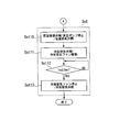
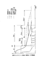
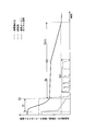
- FIG. 1 is a system diagram of a steam turbine plant in a first embodiment according to the present invention. It is a flowchart (the 1) which shows the stop procedure of the steam turbine plant in 1st embodiment which concerns on this invention. It is a flowchart (the 2) which shows the stop procedure of the steam turbine plant in 1st embodiment which concerns on this invention. It is a graph which shows the change of the metal temperature of a generator output, a rotor rotation speed, and a steam turbine with progress of time in 1st embodiment which concerns on this invention. It is a graph which shows the change of the generator output, the rotor rotation speed, and the metal temperature of a steam turbine with progress of time in the steam turbine plant of a comparative example.
- the steam turbine plant of the present embodiment includes a gas turbine 10, an exhaust heat recovery boiler 20 that generates steam from the exhaust gas EG from the gas turbine 10, and steam from the exhaust heat recovery boiler 20.
- Steam turbine 30 to be driven condenser 40 for returning steam from the steam turbine 30 to water, water supply pump 76 for sending water in the condenser 40 to the exhaust heat recovery boiler 20, a generator 45, and a starting motor 49. Therefore, the steam turbine plant of this embodiment is a combined cycle plant.
- the gas turbine 10 includes a compressor 11 that compresses air A, a combustor 14 that generates fuel gas by burning fuel F in the air compressed by the compressor 11, and a turbine that is driven by high-temperature and high-pressure combustion gas.
- the compressor 11 includes a compressor rotor 12 that rotates about an axis Ar, and a compressor casing 13 that covers the compressor rotor 12.
- the turbine 15 includes a turbine rotor 16 that rotates about an axis Ar, and a turbine casing 17 that covers the turbine rotor 16.
- the compressor rotor 12 and the turbine rotor 16 rotate about the same axis Ar, and are connected to each other to form a gas turbine rotor 19.
- a fuel supply line 65 that supplies fuel F to the combustor 14 is connected to the combustor 14.
- the fuel supply line 65 is provided with a fuel valve 66 for adjusting the flow rate of the fuel F supplied to the combustor 14.
- the exhaust heat recovery boiler 20 is a steam saver 21 that heats water from the condenser 40 with the heat of the exhaust gas EG, and water that is heated by the economizer 21 with the heat of the exhaust gas EG to generate steam. It has the evaporator 22 to generate
- Each of the economizer 21, the evaporator 22, and the superheater 23 has a heat transfer tube for allowing water or steam to pass through the inside and exchanging heat between the water or steam and the exhaust gas EG.
- the evaporator 22 has a drum 22a in addition to the heat transfer tube.
- a heat transfer tube temperature detector 98 for detecting the temperature of the heat transfer tube is provided near the outlet of the heat transfer tube of the superheater 23.
- the steam turbine 30 includes a steam turbine rotor 31 that rotates about an axis Ar, a steam turbine casing 34 that covers the steam turbine rotor 31, and a shaft seal device 39.
- the steam turbine rotor 31 includes a rotor shaft 32 that rotates about an axis Ar, and a plurality of rotor blade rows 33 that are fixed to the rotor shaft 32.
- the plurality of blade rows 33 are arranged in the axial direction in which the axis Ar extends.
- a plurality of stationary blade rows 36 are fixed to the inner peripheral surface of the steam turbine casing 34.
- the plurality of stationary blade rows 36 are arranged in the direction in which the axial direction extends.
- Each of the plurality of stationary blade rows 36 is disposed on the upstream side of the steam flow with respect to any one of the plurality of blade rows 33.
- the first stage stationary blade row disposed on the most upstream side of the steam flow has a metal temperature detector 96 that detects the temperature of the stationary blades constituting the first stage stationary blade row.
- the shaft seal device 39 is a device that suppresses the outflow of steam in the steam turbine casing 34 from the gap between the end of the steam turbine rotor 31 and the steam turbine casing 34 with steam from the outside.
- the steam turbine 30 shown in FIG. 1 is a bifurcated exhaust type steam turbine that diverts incoming steam in two directions.
- the steam turbine 30 of the present embodiment may be a steam turbine of a type that does not divert incoming steam.
- the condenser 40 includes a heat transfer tube 42 through which a cooling medium such as water flows, and a condenser casing 41 that covers the heat transfer tube 42.
- the steam from the steam turbine 30 flows into the condenser casing 41 and is cooled by heat exchange with the cooling medium in the heat transfer pipe 42 to become water.
- the condenser casing 41 is provided with an exhaust line 70 that exhausts the gas in the condenser casing 41 to the outside and reduces the pressure in the condenser casing 41.
- the exhaust line 70 is provided with a vacuum pump 71 that sucks the gas in the condenser casing 41.
- the condenser casing 41 is further provided with an outside air line 72 that guides outside air into the condenser casing 41.
- the outside air line 72 is provided with a vacuum break valve 73.
- the generator 45 includes a generator rotor 46 that rotates about the axis Ar, and a generator casing 47 that covers the generator rotor 46.
- the generator 45 is electrically connected to the external system 63 through a connection line 60.
- the connection line 60 is provided with a transformer 61 and a circuit breaker 62. Further, the connection line 60 is provided with a power detector (output detector) 99 at a position closer to the generator 45 than the circuit breaker 62.
- the gas turbine rotor 19, the steam turbine rotor 31, and the generator rotor 46 are located on the same axis Ar and mechanically connected to each other. Therefore, the combined cycle plant of this embodiment is called a uniaxial combined cycle plant.
- the starting motor 49 rotates these rotors about the axis Ar. Since the generator rotor 46 is connected to the gas turbine rotor 19 and the steam turbine rotor 31 as described above, the amount of power generated by the generator 45, that is, the generator output, is the gas turbine output and the steam turbine output. And the combined output.
- the steam turbine plant of this embodiment includes a low-temperature steam generation source 50 that generates low-temperature steam independently of the exhaust heat recovery boiler 20, a cooling air fan (cooling air supply machine) 55, and a control device 100. And comprising.
- the low-temperature steam generation source 50 includes an auxiliary boiler (second boiler) 51 that generates steam independently of the exhaust heat recovery boiler 20, a pressure control valve 59 that reduces the pressure of the steam generated in the auxiliary boiler 51, and an auxiliary And a temperature reducer 52 that lowers the temperature of the steam generated in the boiler 51.
- the temperature reducer 52 includes a nozzle 53 that sprays water for temperature reduction in the steam generated by the auxiliary boiler 51, a temperature-reduction water adjustment valve 54 that adjusts the flow rate of water for temperature reduction supplied to the nozzle 53, Have The temperature reducer 52 reduces the temperature of the steam generated in the auxiliary boiler 51 to make the steam a low temperature steam.
- the temperature of this low temperature steam is, for example, 140 ° C.
- the cooling air fan 55 sucks outside air and sends the outside air into the steam turbine casing 34 as cooling air.
- the steam turbine plant of the present embodiment further includes a water supply line 75, a main steam line 77, a shut-off valve 78, an adjusting valve 79, an excess steam bypass line 80 (hereinafter simply referred to as a bypass line 80), an excess Steam bypass valve 81 (hereinafter simply referred to as surplus steam valve 81), low temperature steam line 82, low temperature steam valve 83, drain discharge line 84, drain valve 85, shaft seal steam line 86, shaft seal steam A valve 87, a plurality of boiler water discharge lines 88, a plurality of boiler water discharge valves 89, a cooling air line 90, and a cooling air valve 91 are provided.
- the water supply line 75 connects the condenser casing 41 and the economizer 21.
- a water supply pump 76 is provided in the water supply line 75.
- the main steam line 77 connects the superheater 23 and the steam inlet of the steam turbine casing 34.
- the main steam line 77 is provided with a shutoff valve 78 and an adjustment valve (main steam control valve) 79.
- a steam pressure detector 97 for detecting the pressure of the steam is provided in the main steam line 77 on the superheater 23 side of the shutoff valve 78 and the control valve 79.
- a first end of the bypass line 80 is connected to a position closer to the superheater 23 than the shutoff valve 78 and the control valve 79 in the main steam line 77.
- the second end of the bypass line 80 is connected to a position closer to the steam inlet than the shutoff valve 78 and the control valve 79 in the main steam line 77. That is, the bypass line 80 is a line that bypasses the steam from the superheater 23 with respect to the shutoff valve 78 and the regulating valve 79.
- the surplus steam valve 81 is provided in the bypass line 80.
- the first end of the low-temperature steam line 82 is connected to the temperature reducer 52, and the second end of the low-temperature steam line 82 is located at a position closer to the steam inlet than the shut-off valve 78 and the control valve 79 in the main steam line 77. It is connected.
- the low temperature steam valve 83 is provided in the low temperature steam line 82.
- a first end of the drain discharge line 84 is connected to a position closer to the temperature reducer 52 than the low temperature steam valve 83 in the low temperature steam line 82, and a second end of the drain discharge line 84 is connected to the condenser casing 41.
- the drain valve 85 is provided in the drain discharge line 84.
- the first end of the shaft seal steam line 86 is connected to a position closer to the temperature reducer 52 than the connection position to the drain discharge line 84 in the low temperature steam line 82.
- the second end of the shaft seal steam line 86 is connected to the shaft seal device 39 of the steam turbine 30.
- the shaft seal steam valve 87 is provided in the shaft seal steam line 86.
- the first end of the first boiler water discharge line 88a is connected to the drum 22a of the evaporator 22.
- a second end of the first boiler water discharge line 88 a is connected to the condenser casing 41.
- the first boiler water discharge valve 89a is provided in the first boiler water discharge line 88a.
- the first end of the second boiler water discharge line 88b is connected to the vicinity of the outlet of the heat transfer tube constituting the superheater 23.
- a second end of the second boiler water discharge line 88 b is connected to the condenser casing 41.
- the second boiler water discharge valve 89b is provided in the second boiler water discharge line 88b.
- the first end of the cooling air line 90 is connected to the discharge port of the cooling air fan 55.
- the second end of the cooling air line 90 is connected in the main steam line 77 to a position closer to the steam inlet than the shutoff valve 78 and the control valve 79.
- the cooling air valve 91 is provided in the cooling air line 90.
- the control device 100 controls the operations of the valves described above and the operations of various pumps.
- Compressor 11 of gas turbine 10 compresses air A in the atmosphere and supplies the compressed air A to combustor 14. Further, the fuel F from the fuel supply line 65 is also supplied to the combustor 14. In the combustor 14, the fuel F is combusted in the compressed air A, and high-temperature and high-pressure combustion gas is generated. This combustion gas is sent to the turbine 15 to rotate the turbine rotor 16.
- the combustion gas that has rotated the turbine rotor 16 is exhausted from the gas turbine 10 as exhaust gas EG, and is discharged to the outside through the exhaust heat recovery boiler 20.
- Water from the condenser 40 is supplied to the economizer 21 of the exhaust heat recovery boiler 20 via a water supply line 75.
- the economizer 21 heats this water by exchanging heat with the exhaust gas EG.
- the water heated by the economizer 21 is further heated by the evaporator 22 and becomes steam.
- This steam is further heated by the superheater 23 and is supplied to the steam turbine 30 through the main steam line 77 as main steam.
- the steam that has driven the steam turbine 30 returns to water by the condenser 40. This water is supplied again from the condenser 40 to the economizer 21 through the water supply line 75.
- the generator rotor 46 is rotated by the rotation of the gas turbine rotor 19 and the steam turbine rotor 31.
- the generator 45 generates electricity by the rotation of the generator rotor 46.
- the electric power generated by the generator 45 is supplied to the external system 63 via the transformer 61 and the circuit breaker 62.
- the control device 100 When receiving a plant stop command from the outside, the control device 100 sends an instruction to the fuel valve 66 to gradually reduce the opening, and gradually reduces the flow rate of the fuel supplied to the combustor 14 (S1). : Fuel reduction process).
- the gas turbine output gradually decreases.
- the heat energy contained in the exhaust gas EG exhausted from the gas turbine 10 also gradually decreases, so that the steam generated from the exhaust heat recovery boiler 20 is reduced.
- the temperature of the steam gradually decreases. For this reason, when the flow rate of the fuel supplied to the combustor 14 gradually decreases, the steam turbine output also gradually decreases.
- the generator output gradually decreases as shown by the broken line in FIG. 4, and the metal temperature detector as shown by the solid line in FIG.
- the metal temperature of the steam turbine 30 detected at 96 also gradually decreases.
- the generator 45 is electrically connected to the external system 63, so that the generator rotor 46, the gas turbine rotor 19 and the like are indicated by a one-dot chain line in FIG.
- the rotation number corresponding to the frequency of the external system 63 is continuously maintained. For example, when the frequency of the external system 63 is 60 Hz, the generator rotor 46, the gas turbine rotor 19 and the like continue to maintain 3600 rpm, which is the rotation speed corresponding to the 60 Hz.
- the control device 100 When the generator output detected by the output detector 99 is equal to or lower than the predetermined output, the control device 100 sends an opening instruction to the circuit breaker 62 to open the circuit breaker 62 and connect the generator 45 to the external system 63. Disconnect from. Further, the control device 100 sends a close instruction to the shut-off valve 78 and the adjusting valve 79, closes the shut-off valve 78 and the adjust valve 79, and sends a close instruction to the fuel valve 66 to close the fuel valve 66 (S2: (Disconnection / shutoff valve and control valve closing / fuel stop process).
- the transmission of the close instruction to the shutoff valve 78 and the regulating valve 79 in the disconnection / shutoff valve and regulating valve closing / fuel stopping step (S2) is the main steam stopping step.
- the temperature of the first stage stationary blade detected by the metal temperature detector 96 is, for example, 300 ° C.
- the control device 100 When the disengagement / shutoff valve and control valve closing / fuel stop process (S2) is completed, the control device 100 performs a gas turbine cooling process (Sgt), a boiler cooling process (Sb), and a steam turbine as shown in FIG. A cooling process (Sst) is performed in parallel.
- Sgt gas turbine cooling process
- SB boiler cooling process
- Sst steam turbine as shown in FIG.
- a cooling process (Sst) is performed in parallel.
- the control device 100 causes the starter motor 49 to rotate the gas turbine rotor 19 at a rotational speed lower than the rated rotational speed (for example, 3600 rpm). That is, the control device 100 causes the start motor 49 to intermittently execute the spin operation of the gas turbine 10 a plurality of times.
- the controller 100 starts the gas turbine 10 spin operations are executed (Sgt2). Thereafter, the control device 100 causes the starting motor 49 to stop the spin operation.
- the control device 100 causes the start motor 49 to execute the spin operation of the gas turbine 10 (Sgt4). Thereafter, the control device 100 causes the starting motor 49 to stop the spin operation. Similarly, the control device 100 determines whether or not the rotational speed of the gas turbine rotor 19 or the like has reached the turning rotational speed (Sgt5, Sgt7) and causes the starter motor 49 to execute the spin operation (Sgt6, Sgt6). Sgt8).
- the execution time of the first spin operation is made shorter than the execution time of the later spin operation among a plurality of spin operations.
- the moving blades of the compressor rotor 12 and the compressor casing 13 may come into contact with each other, and the turbine There is no risk of contact between the rotor blades of the rotor 16 and the turbine casing 17.
- the execution time of the spin operation is lengthened in order to promote the cooling of the gas turbine 10.
- the control device 100 ends the gas turbine cooling step (Sgt) assuming that the cooling of the gas turbine 10 is completed.
- a temperature detector for detecting a part of the temperature of the gas turbine 10 is provided, and the spin operation is repeatedly executed until the temperature detected by the temperature detector is equal to or lower than a predetermined temperature.
- the gas turbine cooling step (Sgt) may be terminated.
- the boiler cooling step (Sb) is performed in parallel with the gas turbine cooling step (Sgt) described above.
- the two steps are executed in parallel so that a part of the execution time zone of the first step of the two steps overlaps with the execution time zone of the second step. Two steps are performed.
- the control device 100 causes the water in the condenser casing 41 to flow into the heat transfer tube of the exhaust heat recovery boiler 20. Specifically, the control device 100 sends an opening instruction to the boiler water discharge valve 89 while maintaining the state where the water supply pump 76 is driven, and opens the boiler water discharge valve 89 (Sb1: boiler water discharge valve closing step). ). As a result, the water in the condenser casing 41 is supplied into the heat transfer tube of the exhaust heat recovery boiler 20. The water supplied into the heat transfer tube of the exhaust heat recovery boiler 20 exchanges heat with the heat transfer tube to cool the heat transfer tube. Thereafter, the water returns to the condenser casing 41 via the boiler water discharge line 88.
- the water supplied to the exhaust heat recovery boiler 20 is supplied from the economizer 21 to the drum 22a of the evaporator 22, and a part of the water is supplied to the first boiler water discharge valve 89a and the first boiler water discharge line 88a. Then, it returns to the condenser casing 41. Further, another part of the water supplied to the drum 22a of the evaporator 22 passes through the superheater 23, the second boiler water discharge valve 89b, and the second boiler water discharge line 88b, and enters the condenser casing 41. Return to.
- the control device 100 determines whether the boiler cooling is completed (Sb2: cooling completion determination process). The control device 100 determines whether or not the boiler cooling is completed, for example, based on whether or not the temperature detected by the heat transfer tube temperature detector 98 is equal to or lower than a predetermined temperature. Note that the control device 100 determines whether or not a predetermined time has elapsed from the start of the boiler water discharge valve opening process (Sb1), or the flow rate determined in advance from the start of the boiler water discharge valve opening process (Sb1). Depending on whether or not the condensate was supplied to the exhaust heat recovery boiler 20, it may be determined whether or not the boiler cooling has been completed.
- the control device 100 determines that the boiler cooling is completed, the control device 100 sends a stop instruction to the feed water pump 76 and sends a close instruction to the boiler water discharge valve 89.
- the feed water pump 76 is stopped (Sb3: feed water pump stop process), and the boiler water discharge valve 89 is closed (Sb4: boiler water discharge valve closing process).
- the control device 100 determines whether or not the temperature Tm of the first stage stationary blade of the steam turbine 30 detected by the metal temperature detector 96 has become equal to or lower than a predetermined temperature Tms after the boiler cooling step (Sb) ends. Judgment (Sx5: metal temperature judgment step). When the control device 100 determines that the temperature Tm of the first stage stationary blade has become equal to or lower than the predetermined temperature Tms, the control device 100 determines that the cooling of the steam turbine 30 is completed and instructs the vacuum break valve 73 of the condenser 40 to open. At the same time, a stop instruction is sent to the vacuum pump 71.
- the predetermined temperature Tms here is, for example, 170 ° C.
- the water in the condenser casing 41 is supplied into the heat transfer tube of the exhaust heat recovery boiler 20 as described above. If the water contains a large amount of oxygen, the inner surface of the heat transfer tube may be rusted by oxygen. For this reason, it is necessary to suppress the oxygen concentration in the water supplied to the heat transfer tube of the exhaust heat recovery boiler 20. Therefore, in the present embodiment, during the boiler cooling step (Sb), outside air does not flow into the condenser casing 41, and after the boiler cooling step (Sb) is completed, the vacuum breaking step (Sx5) is executed to Outside air is introduced into the vessel casing 41.
- the steam turbine cooling step (Sst) includes a surplus steam supply step (Ssta), a low temperature steam supply step (Sstc), and a drain discharge step (Sstb) executed before the low temperature steam supply step (Sstc). ) And. Further, the steam turbine cooling step (Sst) may include a cooling air supply step (Sstd).
- the control device 100 first sends an opening instruction to the surplus steam valve 81 (Sst1: surplus steam valve opening step). At this time, since the shutoff valve 78 and the control valve 79 are closed, the steam from the exhaust heat recovery boiler 20 does not flow into the steam turbine 30 through the shutoff valve 78 and the control valve 79. The steam from the exhaust heat recovery boiler 20 flows into the steam turbine 30 through a bypass line 80 for the main steam line 77 and an excess steam valve 81 provided in the bypass line 80. The temperature of the steam generated from the exhaust heat recovery boiler 20 is lower than before the fuel supply to the combustor 14 is stopped because the fuel supply to the combustor 14 is stopped at this time.
- the temperature of the steam gradually decreases with time. Furthermore, if the boiler cooling process (Sb) is started at this time, since the heat transfer tube of the exhaust heat recovery boiler 20 is cooled, the temperature of the steam generated from the exhaust heat recovery boiler 20 becomes lower. In addition, the flow rate of the steam generated from the exhaust heat recovery boiler 20 gradually decreases with time, and the pressure of this steam gradually decreases with time. Therefore, the steam turbine 30 is gradually cooled by the steam flowing in through the surplus steam valve 81.
- the control device 100 determines whether or not the pressure Pb detected by the steam pressure detector 97 provided in the main steam line 77 has become equal to or lower than a predetermined pressure Ps.
- Sst2 Steam pressure determination step.
- the control device 100 determines that the pressure Pb detected by the steam pressure detector 97 is not equal to or lower than the predetermined pressure Ps, the control device 100 passes the steam from the exhaust heat recovery boiler 20 through the surplus steam valve 81 to the steam. The supply to the turbine 30 is continued.
- the control device 100 sends an opening instruction to the drain valve 85 provided in the drain discharge line 84 ( Sst3: Drain valve opening process).
- Sst3 Drain valve opening process
- the drain valve 85 is opened, and the low temperature steam from the temperature reducer 52 flows into the condenser 40 through the low temperature steam line 82 and the drain discharge line 84.
- the low-temperature steam from the temperature reducer 52 is cooled in the process of passing through the low-temperature steam line 82, while being cooled and partially becomes water. As described above, the water flows into the condenser 40 through the drain discharge line 84 together with the steam.
- the control device 100 determines whether or not a time Tt from the start of the drain valve opening process (Sst3) to the current time has passed a predetermined time Tts (Sst4: heating). Completion judgment process). If this time Tt has not passed the predetermined time Tts, the control device 100 waits until the time Tt reaches the predetermined time Tts.
- the control device 100 determines that the time Tt has exceeded the predetermined time Tts, the control device 100 determines that the low-temperature steam line 82 has been sufficiently warmed, while sending a close instruction to the surplus steam valve 81 and the drain valve 85, An opening instruction is sent to the low temperature steam valve 83 (Sst5: surplus steam valve closing / drain valve closing / low temperature steam valve opening process).
- Sst5 surplus steam valve closing / drain valve closing / low temperature steam valve opening process.
- the excess steam valve 81 and the drain valve 85 are closed, while the low-temperature steam valve 83 is opened.
- the low temperature steam from the temperature reducer 52 is supplied to the steam turbine 30 via the low temperature steam line 82. For this reason, the steam turbine 30 is cooled by this low temperature steam.
- the surplus steam supply process (Ssta) is started in the surplus steam valve opening process (Sst1) described above, and is ended when the surplus steam valve is closed in Sst5.
- the drain discharge process (Sstb) is started in the drain valve opening process (Sst3), and is ended by the drain valve closing in Sst5.
- the low temperature steam supply step (Sstc) is started by opening the low temperature steam valve in Sst5.
- the drain discharge step (Sstb) is executed, and the low temperature steam line 82 is heated with the low temperature steam. For this reason, at the start of a low temperature steam supply process (Sstc), it can suppress that a low temperature steam passes through the low temperature steam line 82, and a part is liquefied. That is, the drain amount of the low-temperature steam flowing into the steam turbine 30 can be suppressed at the start of the low-temperature steam supply process (Sstc).
- the control device 100 After sending an opening instruction to the low-temperature steam valve 83, the control device 100 determines whether or not boiler cooling has been completed (Sst6: cooling completion determination step), similarly to the cooling completion determination step (Sb2) described above. If the controller 100 determines that the boiler cooling is not completed, the temperature Tm of the first stage stationary blade detected by the metal temperature detector 96 is determined in advance as in the metal temperature determination step (Sx5) described above. It is determined whether or not the temperature has become lower than Tms (Sst7: metal temperature determination step). When the control device 100 determines that the temperature Tm of the first stage stationary blade is not lower than the predetermined temperature Tms, the control device 100 returns to the cooling completion determination step (Sst6).
- Sst6 cooling completion determination step
- the control device 100 sends a close instruction to the low-temperature steam valve 83 because the cooling of the steam turbine 30 is completed (Sst8).
- Low temperature steam valve closing process As a result, the low temperature steam does not flow into the steam turbine 30, and the low temperature steam supply process (Sstc) and the steam turbine cooling process (Sst) are completed.
- the control device 100 When determining that the boiler cooling has been completed in the cooling completion determination step (Sst6), the control device 100 instructs the vacuum break valve 73 of the condenser 40 to open, as in the vacuum break step (Sx6) described above. At the same time, a stop instruction is sent to the vacuum pump 71. Furthermore, the control device 100 sends a close instruction to the low-temperature steam valve 83 (Sst10: vacuum breaking step (shown in FIG. 3)). As a result, outside air flows into the condenser casing 41, and the vacuum state in the condenser casing 41 is destroyed. Further, the low temperature steam valve 83 is closed, and the low temperature steam supply step (Sstc) is completed.
- Sst10 vacuum breaking step (shown in FIG. 3)
- the control device 100 When executing the vacuum breaking step (Sst10), the control device 100 sends an opening instruction to the cooling air valve 91 and sends a driving instruction (or supply instruction) to the cooling air fan 55 (Sst11: cooling air valve opening / cooling air). Fan driving process). As a result, the cooling air from the cooling air fan 55 is supplied to the steam turbine 30 via the cooling air line 90. For this reason, the steam turbine 30 is cooled by this cooling air. As described above, the cooling air supply process (Sstd) is started by executing the cooling air valve opening / cooling air fan driving process (Sst11).
- the control device 100 When executing the cooling air valve opening / cooling air fan driving step (Sst11), the control device 100 performs the first stage static detection detected by the metal temperature detector 96, as in the above-described metal temperature determination step (Sx5, Sst7). It is determined whether or not the blade temperature Tm has become equal to or lower than a predetermined temperature Tms (Sst12: metal temperature determination step). When determining that the temperature Tm of the first stage stationary blade is not lower than the predetermined temperature Tms, the control device 100 waits until the temperature Tm of the first stage stationary blade is lower than the predetermined temperature Tms.
- the control device 100 determines that the temperature Tm of the first stage stationary blade is equal to or lower than the predetermined temperature Tms, the control device 100 determines that the cooling of the steam turbine 30 is completed, and sends a stop instruction to the cooling air fan 55.
- a close instruction is sent to the cooling air valve 91 (Sst13: cooling air fan stop / cooling air valve closing step).
- the cooling air does not flow into the steam turbine 30, and the cooling air supply process (Sstd) and the steam turbine cooling process (Sst) are completed.
- the steam turbine 30 is exclusively cooled by the cooling air from the cooling air fan 55. Therefore, the steam turbine plant of the comparative example is obtained by omitting the low-temperature steam line 82 and the bypass line 80 from the steam turbine plant in the present embodiment.
- the opening degree with respect to the fuel valve 66 is similar to the steam turbine plant of the present embodiment.
- An instruction is sent to gradually decrease (S1: fuel reduction step).
- the control device opens to the circuit breaker 62. An instruction is sent, the circuit breaker 62 is opened, and the generator 45 is disconnected from the external system 63. Further, the control device sends a close instruction to the shut-off valve 78 and the control valve 79, closes the shut-off valve 78 and the control valve 79, sends a close instruction to the fuel valve 66, and closes the fuel valve 66 (S2: Solution). (Line / shutoff valve and control valve closing / fuel stop process).
- the control device like the steam turbine plant of the present embodiment, the gas turbine cooling process (Sgt) and the boiler cooling process (Sb). Execute. However, in the comparative example, the steam turbine cooling step (Sstz) is not executed immediately after the disconnection / shut-off valve and adjustment valve closing / fuel stop step (S2).
- the steam turbine 30 is exclusively cooled by the cooling air from the cooling air fan 55.
- the cooling air also flows into the condenser 40.
- the boiler cooling step (Sb) since it is necessary to suppress the oxygen concentration in the water supplied to the heat transfer tube of the exhaust heat recovery boiler 20, basically during this boiler cooling step (Sb) Air is not allowed to flow into the vessel casing 41.
- the steam breaking process (Ssbz) is performed after the vacuum break process for the condenser 40 is performed.
- the surplus steam supply process (Ssta) and the low temperature steam supply process (Sstc) of the steam turbine cooling process (Sst) in the present embodiment steam is supplied to the steam turbine 30 and the steam turbine 30 is cooled with this steam. .
- air does not flow into the condenser casing 41 in the execution of the surplus steam supply process (Ssta) and the low temperature steam supply process (Sstc). Therefore, in the present embodiment, as shown in FIG. 4, the surplus steam supply process (Ssta) and the low temperature steam supply process (Sstc) of the steam turbine cooling process (Sst) are executed in parallel with the boiler cooling process (Sb). . Therefore, in this embodiment, the cooling start timing of the steam turbine 30 can be advanced, and as a result, the cooling completion timing of the steam turbine 30 and the steam turbine plant can be advanced.
- Steam has a larger heat capacity than air. Therefore, at a stage where the temperature of the steam turbine 30 is high and the temperature difference between the temperature of the steam turbine 30 and the temperature of the low temperature steam is large, the steam turbine per unit time depends on the flow rate of the low temperature steam in the present embodiment.
- the temperature drop of 30 can be increased. Therefore, in this embodiment, the cooling completion timing of the steam turbine 30 can also be advanced from this viewpoint.
- the boiler cooling step (Sb) is performed when the temperature of the steam turbine 30 is decreased by the supply of the low-temperature steam and the temperature difference between the temperature of the steam turbine 30 and the temperature of the low-temperature steam becomes small. If completed, the steam turbine 30 is cooled with cooling air having a large temperature difference with respect to the temperature of the steam turbine 30. For this reason, in this embodiment, if the boiler cooling process (Sb) is completed, the temperature of the steam turbine 30 per unit time after the temperature difference between the temperature of the steam turbine 30 and the temperature of the low-temperature steam becomes small. The temperature drop can be increased. Therefore, in this embodiment, the cooling completion timing of the steam turbine 30 can also be advanced from this viewpoint.
- the surplus steam supply step (Ssta) is executed, and then the low-temperature steam supply step (Sstc) is executed.
- the surplus steam supply process (Ssta) the steam generated in the superheater 23 is supplied to the steam turbine 30 in the same manner as before the disconnection / shut-off valve and control valve closing / fuel stop process (S2).
- the temperature of the steam supplied to the steam turbine 30 hardly changes immediately before and after the disconnection / shutoff valve and adjustment valve closing / fuel stop process (S2). Therefore, in this embodiment, the thermal shock given to the steam turbine 30 immediately after the start of the steam turbine cooling step (Sst) can be minimized.
- the steam turbine 30 of the present embodiment includes an auxiliary boiler 51, a temperature reducer 52, and a low temperature steam line 82 in order to realize a low temperature steam supply process (Sstc).
- the existing steam turbine plant includes an auxiliary boiler 51, a temperature reducer 52, and a shaft seal steam line 86 that guides the low temperature steam from the temperature reducer 52 to the shaft seal device 39 of the steam turbine 30.
- the low temperature steam line 82 branched from the shaft seal steam line 86 and connected to the main steam line 77 is provided, the low temperature steam supply process (Sstc) can be realized. Therefore, if the existing steam turbine plant is a plant as described above, the low-temperature steam supply step (Sstc) can be realized while suppressing the modification cost of the equipment.
- the steam turbine plant of the present embodiment also has a gas turbine 10 and an exhaust heat recovery boiler 20x that generates steam from the exhaust gas EG from the gas turbine 10, as shown in FIG.
- the gas turbine 10 of the present embodiment is the same as the gas turbine 10 of the first embodiment. Therefore, the gas turbine 10 of the present embodiment also includes the compressor 11, the combustor 14, and the turbine 15. Also in this embodiment, a fuel supply line 65 that supplies fuel F to the combustor 14 is connected to the combustor 14. The fuel supply line 65 is provided with a fuel valve 66 for adjusting the flow rate of the fuel F supplied to the combustor 14.
- the steam turbine plant of this embodiment includes a high-pressure steam turbine 30a, an intermediate-pressure steam turbine 30b, and a low-pressure steam turbine 30c as steam turbines.
- the high-pressure steam turbine 30a, the intermediate-pressure steam turbine 30b, and the low-pressure steam turbine 30c are all the same as the steam turbine 30 of the first embodiment, the steam turbine rotor 31, the steam turbine casing 34, and the plurality of stationary blade rows 36.
- a shaft seal device In FIG. 6, only the shaft seal device 39 c of the low pressure steam turbine 30 c is drawn, and the shaft seal devices of the high pressure steam turbine 30 a and the intermediate pressure steam turbine 30 b are omitted.
- the first stage stationary blade of the high-pressure steam turbine 30a is provided with a metal temperature detector 96 that detects the temperature of the first stage stationary blade.
- the exhaust heat recovery boiler 20x of this embodiment has a economizer 21, an evaporator 22, and a superheater 23, like the exhaust heat recovery boiler 20 of the first embodiment.
- the exhaust heat recovery boiler 20x of the present embodiment further includes a reheater 24 that heats the steam exhausted from the intermediate pressure steam turbine 30b.
- Each of the economizer 21, the evaporator 22, the reheater 24, and the superheater 23 has a heat transfer tube for allowing water or steam to pass therethrough and for heat exchange between the water or steam and the exhaust gas EG. .
- the evaporator 22 of the present embodiment also includes a drum 22a in addition to the heat transfer tube.
- a heat transfer tube temperature detector 98 for detecting the temperature of the heat transfer tube is provided near the outlet of the heat transfer tube of the superheater 23.
- the exhaust heat recovery boiler 20x includes one or more booster pumps (not shown) that pressurize the water supplied to the economizer 21.
- the condenser 40 of the present embodiment is the same as the condenser 40 of the first embodiment. Therefore, the condenser 40 of this embodiment also has a heat transfer tube through which a cooling medium such as water flows, and a condenser casing 41 that covers the heat transfer tube.
- the steam from the low-pressure steam turbine 30c flows into the condenser casing 41, and is cooled by heat exchange with the cooling medium in the heat transfer pipe to become water.
- the condenser casing 41 is provided with an exhaust line 70 as in the condenser 40 of the first embodiment.
- the exhaust line 70 is provided with a vacuum pump 71 that sucks the gas in the condenser casing 41.
- the condenser casing 41 is further provided with an outside air line 72 that guides outside air into the condenser casing 41.
- the outside air line 72 is provided with a vacuum break valve 73.
- the generator 45 of the present embodiment is the same as the generator 45 of the first embodiment. Therefore, the generator 45 of this embodiment also has a generator rotor 46 and a generator casing 47.
- the generator 45 is electrically connected to the external system 63 through the connection line 60 as in the first embodiment.
- the connection line 60 is provided with a transformer 61 and a circuit breaker 62. Further, the connection line 60 is provided with a power detector (output detector 99) at a position closer to the generator 45 than the circuit breaker 62.
- the gas turbine rotor 19, the steam turbine rotor 31 of each of the steam turbines 30a, 30b, and 30c, and the generator rotor 46 are located on the same axis Ar and are mechanically connected to each other. Therefore, the combined cycle plant of this embodiment is also called a uniaxial combined cycle plant, as in the first embodiment.
- the starting motor 49 rotates these rotors about the axis Ar.
- the steam turbine plant of this embodiment also includes a low-temperature steam generation source 50, a cooling air fan 55, and a control device 100x, similarly to the steam turbine plant of the first embodiment.
- the low-temperature steam generation source 50 is generated by an auxiliary boiler 51 that generates steam independently of the exhaust heat recovery boiler 20x, a pressure control valve 59 that reduces the pressure of the steam generated in the auxiliary boiler 51, and the auxiliary boiler 51.
- a temperature reducer 52 that lowers the temperature of the steam.
- the temperature reducer 52 includes a nozzle 53 that sprays water for temperature reduction in the steam generated by the auxiliary boiler 51, a temperature-reduction water adjustment valve 54 that adjusts the flow rate of water for temperature reduction supplied to the nozzle 53, Have
- the steam turbine plant of the present embodiment further includes a water supply line 75, a first main steam line 77a, a second main steam line 77b, a first shutoff valve 78a, a second shutoff valve 78b, and a first regulator valve.
- Main steam control valve 79a
- second control valve main steam control valve
- first surplus steam bypass line 80a hereinafter simply referred to as first bypass line 80a
- second surplus steam bypass Line 80b hereinafter simply referred to as second bypass line 80b
- first surplus steam bypass valve 81a hereinafter simply referred to as first surplus steam valve 81a
- second surplus steam bypass valve 81b hereinafter referred to as “second surplus steam bypass valve 81a”.
- the water supply line 75 connects the condenser casing 41 and the economizer 21.
- a water supply pump 76 is provided in the water supply line 75.
- the first main steam line 77a connects the superheater 23 and the steam inlet of the high-pressure steam turbine 30a.
- the first main steam line 77a is provided with a first shut-off valve 78a and a first adjusting valve 79a. Further, in the first main steam line 77a, a steam pressure detector 97 for detecting steam pressure is provided on the superheater 23 side of the first shutoff valve 78a and the first control valve 79a.
- a first end of the first bypass line 80a is connected to a position closer to the superheater 23 than the first shutoff valve 78a and the first control valve 79a in the first main steam line 77a.
- the second end of the first bypass line 80a is connected to a position on the steam inlet side of the high-pressure steam turbine 30a with respect to the first shut-off valve 78a and the first control valve 79a in the first main steam line 77a.
- the first surplus steam valve 81a is provided in the first bypass line 80a.
- the high-pressure steam recovery line 92 connects the steam outlet of the high-pressure steam turbine 30a and the steam inlet of the reheater 24.
- a first end of the ventilator line 93 is connected to the high-pressure steam recovery line 92.
- the second end of the ventilator line 93 is connected to the condenser casing 41.
- the ventilator valve 94 is provided in the ventilator line 93.
- the second main steam line 77b connects the steam outlet of the reheater 24 and the steam inlet of the intermediate pressure steam turbine 30b.
- the second main steam line 77b is provided with a second shut-off valve 78b and a second adjusting valve 79b.
- the first end of the second bypass line 80b is connected to a position closer to the superheater 23 than the first shut-off valve 78a and the first control valve 79a in the first main steam line 77a.
- the second end of the second bypass line 80b is connected to a position on the steam inlet side of the intermediate pressure steam turbine 30b in the second main steam line 77b with respect to the second shutoff valve 78b and the second control valve 79b. Yes.
- the second surplus steam valve 81b is provided in the second bypass line 80b.
- the low pressure steam line 95 connects the steam outlet of the intermediate pressure steam turbine 30b and the steam inlet of the low pressure steam turbine 30c.
- the low temperature steam line 82x includes a main low temperature steam line 82m, a first low temperature steam line 82a, and a second low temperature steam line 82b.
- the main low-temperature steam line 82m is connected to the temperature reducer 52.
- the first end of the first low-temperature steam line 82a is connected to the main low-temperature steam line 82m.
- the second end of the first low-temperature steam line 82a is connected to a position closer to the steam inlet side of the high-pressure steam turbine 30a than the first shut-off valve 78a and the first control valve 79a in the first main steam line 77a.
- the first low temperature steam valve 83a is provided in the first low temperature steam line 82a.
- the first end of the first drain discharge line 84a is connected to a position closer to the temperature reducer 52 than the first low temperature steam valve 83a in the first low temperature steam line 82a.
- a second end of the first drain discharge line 84 a is connected to the condenser casing 41.
- the first drain valve 85a is provided in the first drain discharge line 84a.
- the first end of the second low-temperature steam line 82b is connected to the main low-temperature steam line 82m.
- the second end of the second low-temperature steam line 82b is connected to a position closer to the steam inlet side of the intermediate pressure steam turbine 30b than the second shutoff valve 78b and the second control valve 79b in the second main steam line 77b.
- the second low temperature steam valve 83b is provided in the second low temperature steam line 82b.
- the first end of the second drain discharge line 84b is connected to a position closer to the temperature reducer 52 than the second low temperature steam valve 83b in the second low temperature steam line 82b.
- a second end of the first drain discharge line 84 a is connected to the condenser casing 41.
- the second drain valve 85b is provided in the second drain discharge line 84b.
- the first end of the shaft seal steam line 86 is connected to the main low temperature steam line 82m.
- the second end of the shaft seal steam line 86 is connected to the shaft seal device 39 of the low pressure steam turbine 30c.
- the shaft seal steam valve 87 is provided in the shaft seal steam line 86.
- the 1st end of the boiler water discharge line 88 is connected to the exit vicinity of the heat exchanger tube which comprises the superheater 23 similarly to the boiler water discharge line 88 of 1st embodiment.
- the first end of the first boiler water discharge line 88a is connected to the drum 22a of the evaporator 22.
- a second end of the first boiler water discharge line 88 a is connected to the condenser casing 41.
- the first boiler water discharge valve 89a is provided in the first boiler water discharge line 88a.
- the first end of the second boiler water discharge line 88b is connected to the vicinity of the outlet of the heat transfer tube constituting the superheater 23.
- a second end of the second boiler water discharge line 88 b is connected to the condenser casing 41.
- the second boiler water discharge valve 89b is provided in the second boiler water discharge line 88b.
- the cooling air line 90x has a main cooling air line 90m, a first cooling air line 90a, and a second cooling air line 90b.
- the main cooling air line 90 m is connected to the discharge port of the cooling air fan 55.
- the first end of the first cooling air line 90a is connected to the main cooling air line 90m.
- the second end of the first cooling air line 90a is connected to a position on the steam inlet side of the high-pressure steam turbine 30a with respect to the first shut-off valve 78a and the first control valve 79a in the first main steam line 77a.
- the first cooling air valve 91a is provided in the first cooling air line 90a.
- the first end of the second cooling air line 90b is connected to the main cooling air line 90m.
- the second end of the second cooling air line 90b is connected to a position closer to the steam inlet of the intermediate pressure steam turbine 30b than the second shutoff valve 78b and the second control valve 79b in the second main steam line 77b.
- the second cooling air valve 91b is provided in the second cooling air line 90b.
- the control device 100x controls the operations of the valves described above and the operations of various pumps.
- the gas turbine 10 of this embodiment also operates in the same manner as the gas turbine 10 of the first embodiment.
- the combustion gas obtained by rotating the turbine rotor 16 of the gas turbine 10 is exhausted from the gas turbine 10 as exhaust gas EG, and is discharged to the outside through the exhaust heat recovery boiler 20x.
- Water from the condenser 40 is supplied to the economizer 21 of the exhaust heat recovery boiler 20 x via the water supply line 75.
- the economizer 21 heats this water by exchanging heat with the exhaust gas EG.
- the water heated by the economizer 21 is further heated by the evaporator 22 and becomes steam. This steam is further heated by the superheater 23, and is supplied as high pressure steam to the high pressure steam turbine 30a via the first main steam line 77a.
- the steam that has driven the high-pressure steam turbine 30 a flows into the reheater 24 through the high-pressure steam recovery line 92.
- the steam flowing into the reheater 24 is heated by the reheater 24.
- the steam heated by the reheater 24 is supplied as intermediate pressure steam (or reheat steam) to the intermediate pressure steam turbine 30b via the second main steam line 77b.
- the steam that has driven the intermediate pressure steam turbine 30 b is supplied to the low pressure steam turbine 30 c via the low pressure steam line 95.
- the steam that has driven the low-pressure steam turbine 30 c returns to water by the condenser 40. This water is supplied again to the economizer 21 from the condenser 40 through the water supply line 75.
- the generator rotor 46 is rotated by the rotation of the gas turbine rotor 19 and the steam turbine rotor 31.
- the generator 45 generates electricity by the rotation of the generator rotor 46.
- the electric power generated by the generator 45 is supplied to the external system 63 via the transformer 61 and the circuit breaker 62.
- the control device 100x when receiving a plant stop command from the outside, the control device 100x sends an instruction to the fuel valve 66 to gradually reduce the opening, and gradually reduces the flow rate of the fuel supplied to the combustor 14.
- S1 Fuel reduction process
- the control apparatus 100x performs a disconnection / shut-off valve and a regulating valve closing / fuel stop process (S2x) similarly to 1st embodiment.
- the control device 100x applies the first control valve 78a, the first control valve 79a, the second control valve 78b, and the second control valve 79b.
- a close instruction is sent to close the first shutoff valve 78a, the first control valve 79a, the second shutoff valve 78b, and the second control valve 79b.
- the control device 100x When the disengagement / shut-off valve and control valve closing / fuel stop process (S2x) is completed, the control device 100x, like the first embodiment, performs the gas turbine cooling process (Sgt), the boiler cooling process (Sb), and the steam.
- the turbine cooling process (Sstx) is executed in parallel.
- the gas turbine cooling process (Sgt) of this embodiment is the same process as the gas turbine cooling process (Sgt) of the first embodiment.
- the boiler cooling process (Sb) of this embodiment is the same process as the boiler cooling process (Sb) of the first embodiment.
- the steam turbine cooling process (Sstx) of the present embodiment is slightly different from the gas turbine cooling process (Sst) of the first embodiment. Therefore, below, description of the gas turbine cooling process (Sgt) and boiler cooling process (Sb) of this embodiment is abbreviate
- the steam turbine cooling process (Sstx) of this embodiment also includes a surplus steam supply process, a low temperature steam supply process, and a drain discharge process executed before the low temperature steam supply process, as in the first embodiment. Furthermore, the steam turbine cooling process (Sstx) of this embodiment may also include a cooling air supply process.
- the control device 100x first sends an opening instruction to the ventilator valve 94 (Sstx1: ventilator valve opening step).
- the ventilator valve 94 is opened, and the steam outlet of the high-pressure steam turbine 30 a and the condenser casing 41 communicate with each other via the high-pressure steam recovery line 92 and the ventilator line 93.
- the control apparatus 100x performs the surplus steam valve opening process (Sstx1a) similar to the surplus steam valve opening process (Sst1) of the first embodiment.
- the control device 100x sends an opening instruction to the first surplus steam valve 81a and the second surplus steam valve 81b.
- a part of the steam from the superheater 23 flows into the high-pressure steam turbine 30a via the first bypass line 80a, and the high-pressure steam turbine 30a is cooled by this steam.
- the steam that has flowed into the high-pressure steam turbine 30 a is exhausted into the condenser 40 through the high-pressure steam recovery line 92 and the ventilator line 93.
- the other part of the steam from the superheater 23 flows into the intermediate pressure steam turbine 30b via the second bypass line 80b, and the intermediate pressure steam turbine 30b is cooled by this steam.
- the steam that has flowed into the intermediate pressure steam turbine 30b flows into the low pressure steam turbine 30c via the low pressure steam line 95, and the low pressure steam turbine 30c is cooled by this steam.
- the control apparatus 100x performs a steam pressure judgment process (Sst2) after the surplus steam valve opening process (Sstx1a) as in the first embodiment.
- Sst2 a steam pressure judgment process
- the control device 100x determines that the pressure Pb detected by the steam pressure detector 97 is equal to or lower than a predetermined pressure Ps in this steam pressure determination step (Sst2)
- the drain valve opening step A drain valve opening step (Sstx3) similar to Sst3) is executed.
- the control device 100x sends an opening instruction to the first drain valve 85a and the second drain valve 85b.
- the control apparatus 100x performs the heating completion determination process (Sst4) after the drain valve opening process (Sstx3) as in the first embodiment.
- the controller 100x determines that the time Tt from the start of the drain valve opening process (Sstx3) to the current time has passed a predetermined time Tts in the heating completion determination process (Sst4), the first low-temperature steam line Assuming that 82a and the second low-temperature steam line 82b are sufficiently warmed, the surplus steam valve closing / drain valve closing / similar to the surplus steam valve closing / drain valve closing / low temperature steam valve opening process (Sst5) of the first embodiment / A low temperature steam valve opening process (Sstx5) is performed.
- the control device 100x includes a first surplus steam valve 81a, a second surplus steam valve 81b, a first drain valve 85a, and A close command is sent to the second drain valve 85b, and an open instruction is sent to the first low-temperature steam valve 83a and the second low-temperature valve.
- a part of the low temperature steam from the temperature reducer 52 is supplied to the high pressure steam turbine 30a via the first low temperature steam line 82a. For this reason, the high pressure steam turbine 30a is cooled by this low temperature steam.
- the other part of the low temperature steam from the temperature reducer 52 is supplied to the intermediate pressure steam turbine 30b via the second low temperature steam line 82b. For this reason, the intermediate pressure steam turbine 30b is cooled by this low temperature steam.
- the low temperature steam supplied to the intermediate pressure steam turbine 30 b flows into the low pressure steam turbine 30 c through the low pressure steam line 95. For this reason, the low pressure steam turbine 30c is cooled by this low temperature steam.
- the surplus steam supply process of the present embodiment starts with the ventilator valve opening process (Sstx1) described above, and ends when the first surplus steam valve 81a and the second surplus steam valve 81b are closed in Sstx5. Moreover, the drain discharge process of this embodiment is started by the drain valve opening process (Sstx3), and is completed by closing the first drain valve 85a and the second drain valve 85b in Sstx5. Further, the low temperature steam supply process is started by opening the first low temperature steam valve 83a and the second low temperature steam valve 83b in Sstx5.
- the control device 100x After sending an opening instruction to the first low-temperature steam valve 83a and the second low-temperature steam valve 83b, the control device 100x performs the cooling completion determination step (Sst6) in the same manner as the cooling completion determination step (Sst6) of the first embodiment. Execute. When determining that the boiler cooling is not completed in this cooling completion determination step (Sst6), the control device 100x performs the metal temperature determination step (Sst7) in the same manner as the metal temperature determination step (Sst7) of the first embodiment. Execute. When the control device 100x determines that the temperature Tm of the first stage stationary blade detected by the metal temperature detector 96 is not lower than or equal to the predetermined temperature Tms in this metal temperature determination step (Sst7), the cooling is completed.
- the process returns to the determination step (Sst6).
- the control device 100x determines that the temperature Tm of the first stage stationary blade has become equal to or lower than the predetermined temperature Tms, the cooling of each steam turbine 30a, 30b, 30c is completed, and the low temperature of the first embodiment is determined.
- a low temperature steam valve closing step (Sstx8) similar to the steam valve closing step (Sst8) is executed.
- the control device 100x sends a close instruction to the first low temperature steam valve 83a and the second low temperature steam valve 83b.
- the low temperature steam does not flow into each of the steam turbines 30a, 30b, 30c, and the low temperature steam supply process and the steam turbine cooling process (Sstx) are completed.
- the control device 100x When determining that the boiler cooling is completed in the cooling completion determination step (Sst6), the control device 100x performs the same vacuum destruction step (Sstx10 (shown in FIG. 8) as the vacuum destruction step (Sst10) of the first embodiment). ). However, in this vacuum breaking step (Sstx10), the control device 100x sends an opening instruction to the vacuum breaking valve 73 of the condenser 40 and sends a stop instruction to the vacuum pump 71, and then the first low-temperature steam valve 83a. And a close instruction to the second low-temperature steam valve 83b. As a result, outside air flows into the condenser casing 41, and the vacuum state in the condenser casing 41 is destroyed. Furthermore, the first low-temperature steam valve 83a and the second low-temperature steam valve 83b are closed, and the low-temperature steam supply process is completed.
- the control device 100x When executing the vacuum breaking process (Sstx10), the control device 100x performs the same cooling air valve opening / cooling air fan driving process (Sstx11) as the cooling air valve opening / cooling air fan driving process (Sst11) of the first embodiment. Execute. However, in this cooling air valve opening / cooling air fan driving step (Sstx11), the control device 100x sends an opening instruction to the first cooling air valve 91a and the second cooling air valve 91b. As a result, a part of the cooling air from the cooling air fan 55 is supplied to the high-pressure steam turbine 30a via the first cooling air line 90a. For this reason, the high-pressure steam turbine 30a is cooled by this cooling air.
- the cooling air supply process of this embodiment is started by executing the cooling air valve opening / cooling air fan driving process (Sstx11).
- the control device 100x executes the metal temperature determination step (Sst12) as in the metal temperature determination step (Sst12) of the first embodiment.
- the controller 100x determines in the metal temperature determination step (Sst12) that the temperature Tm of the first stage stationary blade detected by the metal temperature detector 96 has become equal to or lower than a predetermined temperature Tms, each steam turbine 30a. , 30b, 30c is completed, the same cooling air fan stop / cooling air valve closing step (Sstx13) as the cooling air fan stop / cooling air valve closing step (Sst13) of the first embodiment is executed.
- the bypass line 80 and the surplus steam valve 81 are provided in order to perform the surplus steam supply process.
- the surplus steam supply process can be performed without providing the bypass line 80 and the surplus steam valve 81.
- the control device 100x sends an opening instruction to the shutoff valve 78 and indicates that the rice opening is reduced to the control valve 79. Send a fine opening instruction.
- the steam from the superheater 23 flows into the steam turbine 30 through the main steam line 77, the shutoff valve 78 and the control valve 79.
- the surplus steam supply process is executed in the steam turbine cooling process. However, it is not necessary to execute this surplus steam supply process in the steam turbine cooling process. In this case, the bypass line and the surplus steam valve for performing the surplus steam supply process can be omitted.
- low temperature steam having a constant temperature is supplied to the steam turbine in the low temperature steam supply step.
- the control device may instruct the temperature reducer 52 to lower the temperature of the low temperature steam.
- the predetermined condition is that the time from the start of the low-temperature steam supply process to the present time has passed for a predetermined time or more, and the temperature of the first stage stationary blade of the steam turbine is equal to or lower than the predetermined temperature. Have become.
- As a method for lowering the temperature of the low-temperature steam there is a method in which the amount of water sprayed from the nozzle 53 of the temperature reducer 52 is increased by increasing the opening degree of the temperature-reducing water adjustment valve 54. As described above, when the temperature of the low-temperature steam is lowered according to the conditions in the low-temperature steam supply step, the thermal shock to the steam turbine can be suppressed and the steam turbine 30 can be efficiently cooled.
- the steam turbine plant of the above embodiment includes a starter motor 49 that rotates the gas turbine rotor 19 at the time of start-up.
- a starter motor 49 that rotates the gas turbine rotor 19 at the time of start-up.
- All of the steam turbine plants of the above embodiments are uniaxial combined cycle plants. However, it may be a two-shaft combined cycle plant that includes a generator driven by the rotation of the gas turbine rotor 19 and a generator that is different from the generator and generates power by the rotation of the steam turbine rotor. .
- the generator is driven by the steam turbine.
- other devices such as a pump may be driven by the steam turbine.
- the steam turbine plant of the above embodiment is a combined cycle plant including a gas turbine, an exhaust heat recovery boiler, and a steam turbine.
- the steam turbine plant may not include a gas turbine.
- the boiler becomes a conventional boiler with a furnace.
- the low temperature steam generation source 50 includes an auxiliary boiler 51 and a temperature reducer 52.
- the steam generated by the auxiliary boiler is steam having a temperature sufficient to cool the steam turbine, it is not necessary to provide the temperature reducer 52.
- the boiler of the operating steam turbine plant is used as an auxiliary boiler. Also good.
- the end of cooling of the steam turbine can be accelerated.
Landscapes
- Engineering & Computer Science (AREA)
- Mechanical Engineering (AREA)
- General Engineering & Computer Science (AREA)
- Chemical & Material Sciences (AREA)
- Combustion & Propulsion (AREA)
- Physics & Mathematics (AREA)
- Thermal Sciences (AREA)
- Life Sciences & Earth Sciences (AREA)
- Sustainable Development (AREA)
- Sustainable Energy (AREA)
- Control Of Turbines (AREA)
- Engine Equipment That Uses Special Cycles (AREA)
Abstract
Description
本願は、2018年5月14日に、日本国に出願された特願2018-093301号に基づき優先権を主張し、この内容をここに援用する。
蒸気を発生するボイラーと、前記蒸気の発生のための燃料の流量を調節する燃料弁と、前記ボイラーと独立して、低温蒸気を発生する低温蒸気発生源と、前記ボイラーからの蒸気で駆動する蒸気タービンと、前記ボイラーで発生した蒸気を前記蒸気タービンの蒸気入口に導く主蒸気ラインと、前記主蒸気ラインに設けられ、前記ボイラーから前記蒸気タービンに流入する蒸気流量を調節する主蒸気調節弁と、前記低温蒸気発生源に接続され、前記低温蒸気発生源からの前記低温蒸気を前記主蒸気ライン中で前記主蒸気調節弁よりも前記蒸気タービン側の位置に導く低温蒸気ラインと、前記低温蒸気ラインに設けられ、前記低温蒸気ラインを流れる前記低温蒸気の流量を調節する低温蒸気弁と、制御装置と、を備える。前記制御装置は、前記燃料弁への閉指示を送った後に、前記低温蒸気弁に開指示を送る。
蒸気を発生するボイラーと、前記ボイラーからの蒸気で駆動する蒸気タービンと、前記ボイラーで発生した蒸気を前記蒸気タービンの蒸気入口に導く主蒸気ラインと、前記主蒸気ラインに設けられ、前記ボイラーから前記蒸気タービンに流入する蒸気流量を調節する主蒸気調節弁と、を備える蒸気タービンプラントの冷却方法である。この冷却方法は、前記ボイラーで蒸気の発生のための燃料供給を停止する燃料停止工程と、前記燃料停止工程後に、前記ボイラーと独立して、低温蒸気を発生する低温蒸気発生源からの低温蒸気を、前記主蒸気ライン中で前記主蒸気調節弁よりも前記蒸気タービン側の位置に導く低温蒸気供給工程と、を実行する。
本発明に係る蒸気タービンプラントの第一実施形態について、図1~図5を参照して説明する。
本発明に係る蒸気タービンプラントの第二実施形態について、図6及び図7を参照して説明する。
以上の各実施形態では、低温蒸気供給工程中に、ボイラー冷却が完了した場合、この低温蒸気供給工程を終了してから、冷却空気供給工程を実行する。しかしながら、ボイラー冷却が完了した後も、第一段静翼の温度が予め定められた温度以下になるまで、低温蒸気供給工程を継続してもよい。この場合、冷却空気ファン55や冷却空気ライン90xを設ける必要はない。
11:圧縮機
12:圧縮機ロータ
13:圧縮機ケーシング
14:燃焼器
15:タービン
16:タービンロータ
17:タービンケーシング
19:ガスタービンロータ
20,20x:排熱回収ボイラー(又はボイラー)
21:節炭器
22:蒸発器
22a:ドラム
23:過熱器
24:再熱器
30:蒸気タービン
30a:高圧蒸気タービン
30b:中圧蒸気タービン
30c:低圧蒸気タービン
31:蒸気タービンロータ
32:ロータ軸
33:動翼列
34:蒸気タービンケーシング
36:静翼列
39,39c:軸封装置
40:復水器
41:復水器ケーシング
42:伝熱管
45:発電機
46:発電機ロータ
47:発電機ケーシング
49:起動モータ
50:低温蒸気発生源
51:補助ボイラー(第二ボイラー)
52:減温器
53:ノズル
54:減温水調節弁
55:冷却空気ファン(冷却空気供給機)
59:圧力制御弁
60:接続線
63:外部系統
61:変圧器
62:遮断器
65:燃料供給ライン
66:燃料弁
70:排気ライン
71:真空ポンプ
72:外気ライン
73:真空破壊弁
75:給水ライン
76:給水ポンプ
77:主蒸気ライン
77a:第一主蒸気ライン
77b:第二主蒸気ライン
78:遮断弁
78a:第一遮断弁
78b:第二遮断弁
79:加減弁(主蒸気調節弁)
79a:第一加減弁(主蒸気調節弁)
79b:第二加減弁(主蒸気調節弁)
80:余剰蒸気バイパスライン(又は、バイパスライン)
80a:第一余剰蒸気バイパスライン(又は、第一バイパスライン)
80b:第二余剰蒸気バイパスライン(又は、第二バイパスライン)
81:余剰蒸気バイパス弁(又は、余剰蒸気弁)
81a:第一余剰蒸気バイパス弁(又は、第一余剰蒸気弁)
81b:第二余剰蒸気バイパス弁(又は、第二余剰蒸気弁)
82,82x:低温蒸気ライン
82m:主低温蒸気ライン
82a:第一低温蒸気ライン
82b:第二低温蒸気ライン
83:低温蒸気弁
83a:第一低温蒸気弁
83b:第二低温蒸気弁
84:ドレン排出ライン
84a:第一ドレン排出ライン
84b:第二ドレン排出ライン
85:ドレン弁
85a:第一ドレン弁
85b:第二ドレン弁
86:軸封蒸気ライン
87:軸封蒸気弁
88:ボイラー水排出ライン
88a:第一ボイラー水排出ライン
88b:第二ボイラー水排出ライン
89:ボイラー水排出弁
89a:第一ボイラー水排出弁
89b:第二ボイラー水排出弁
90,90x:冷却空気ライン
90m:主冷却空気ライン
90a:第一冷却空気ライン
90b:第二冷却空気ライン
91:冷却空気弁
91a:第一冷却空気弁
91b:第二冷却空気弁
92:高圧蒸気回収ライン
93:ベンチレータライン
94:ベンチレータ弁
95:低圧蒸気ライン
96:メタル温度検知器
97:蒸気圧力検知器
98:伝熱管温度検知器
99:電力検知器(又は出力検知器)
100,100x:制御装置
A:空気
EG:排気ガス
F:燃料
Ar:軸線
Claims (18)
- 蒸気を発生するボイラーと、
前記蒸気の発生のための燃料の流量を調節する燃料弁と、
前記ボイラーと独立して、低温蒸気を発生する低温蒸気発生源と、
前記ボイラーからの蒸気で駆動する蒸気タービンと、
前記ボイラーで発生した蒸気を前記蒸気タービンの蒸気入口に導く主蒸気ラインと、
前記主蒸気ラインに設けられ、前記ボイラーから前記蒸気タービンに流入する蒸気流量を調節する主蒸気調節弁と、
前記低温蒸気発生源に接続され、前記低温蒸気発生源からの前記低温蒸気を前記主蒸気ライン中で前記主蒸気調節弁よりも前記蒸気タービン側の位置に導く低温蒸気ラインと、
前記低温蒸気ラインに設けられ、前記低温蒸気ラインを流れる前記低温蒸気の流量を調節する低温蒸気弁と、
制御装置と、
を備え、
前記制御装置は、前記燃料弁への閉指示を送った後に、前記低温蒸気弁に開指示を送る、
蒸気タービンプラント。 - 請求項1に記載の蒸気タービンプラントにおいて、
前記低温蒸気発生源は、前記ボイラーである第一ボイラーとは独立して蒸気を発生する第二ボイラーと、前記第二ボイラーからの蒸気の温度を低下させて、前記低温蒸気を生成する減温器と、を有する、
蒸気タービンプラント。 - 請求項1又は2に記載の蒸気タービンプラントにおいて、
前記低温蒸気ライン中で、前記低温蒸気弁よりも前記低温蒸気発生源側に接続され、前記低温蒸気ライン中の前記低温蒸気及び前記低温蒸気のドレンを排出するドレン排出ラインと、
前記ドレン排出ライン中に設けられているドレン弁と、
を備え、
前記制御装置は、前記燃料弁に対して閉指示を送った後に、前記ドレン弁に開指示を送り、前記ドレン弁に開指示を送ってから所定時間経過すると、前記ドレン弁に閉指示を送ると共に前記低温蒸気弁に開指示を送る、
蒸気タービンプラント。 - 請求項1から3のいずれか一項に記載の蒸気タービンプラントにおいて、
前記主蒸気ライン中で前記主蒸気調節弁よりも前記ボイラー側の位置から分岐し、前記ボイラーから蒸気を、前記主蒸気ライン中で前記主蒸気調節弁よりも前記蒸気タービン側の位置に導くバイパスラインと、
前記バイパスラインを流れる蒸気の流量を調節する余剰蒸気弁と、
前記主蒸気ライン中で前記主蒸気調節弁よりも前記ボイラー側の位置での圧力を検知する圧力検知器と、
を備え、
前記制御装置は、前記燃料弁への閉指示の送信に伴って前記主蒸気調節弁に閉指示を送ると共に、前記余剰蒸気弁に開指示を送り、前記圧力検知器で検知された圧力が予め定められた圧力以下になると、前記低温蒸気弁に開指示を送る、
蒸気タービンプラント。 - 請求項1から3のいずれか一項に記載の蒸気タービンプラントにおいて、
前記主蒸気ライン中で前記主蒸気調節弁よりも前記ボイラー側の位置での圧力を検知する圧力検知器を備え、
前記制御装置は、前記燃料弁への閉指示の送信に伴って前記主蒸気調節弁に弁開度を小さくする旨を示す微開指示を送り、前記圧力検知器で検知された圧力が予め定められた圧力以下になると、前記低温蒸気弁に開指示を送る、
蒸気タービンプラント。 - 請求項1から5のいずれか一項に記載の蒸気タービンプラントにおいて、
前記蒸気タービンからの蒸気を水に戻す復水器と、
前記復水器内の水を前記ボイラーに導く給水ラインと、
前記給水ラインに設けられ、前記前記復水器内の水をボイラーに送るポンプと、
前記ボイラーで水又は蒸気が通る管又はドラムに接続され、前記管又はドラム内の水又は蒸気をボイラー外に排出するボイラー水排出ラインと、
前記ボイラー水排出ラインに設けられ、前記ボイラー水排出ラインを流れる流体の流量を調節するボイラー水排出弁と、
を備え、
前記制御装置は、前記燃料弁に対して閉指示を送った後に、前記ポンプの駆動を継続した状態で、前記ボイラー水排出弁に開指示を送る、
蒸気タービンプラント。 - 請求項6に記載の蒸気タービンプラントにおいて、
前記ボイラー水排出ラインは、前記復水器に接続されている、
蒸気タービンプラント。 - 請求項6又は7に記載の蒸気タービンプラントにおいて、
前記制御装置は、前記低温蒸気弁が開いている時間帯の少なくとも一部が、前記ボイラー水排出弁が開いている時間帯に重なるよう、前記ボイラー水排出弁に対して開指示を送る、
蒸気タービンプラント。 - 請求項1から8のいずれか一項に記載の蒸気タービンプラントにおいて、
前記蒸気タービンで、前記ボイラーからの蒸気が接する箇所の温度を検知する温度検知器を備え、
前記制御装置は、前記温度検知器で検知された温度が予め定められた温度以下になると、前記低温蒸気弁に閉指示を送る、
蒸気タービンプラント。 - 請求項6から8のいずれか一項に記載の蒸気タービンプラントにおいて、
前記蒸気タービンで、前記ボイラーからの蒸気が接する箇所の温度を検知する温度検知器と、
前記蒸気タービンを冷却するための冷却空気を前記蒸気タービン内に送る冷却空気供給機と、
前記冷却空気供給機に接続され、前記主蒸気ライン中で前記主蒸気調節弁よりも前記蒸気タービン側の位置に前記冷却空気を導く冷却空気ラインと、
を備え、
前記制御装置は、前記温度検知器で検知された温度が予め定められた温度以下になる前に、前記ボイラーの冷却が完了したと判断すると、前記低温蒸気弁に閉指示を送った後に前記冷却空気供給機に供給指示を送り、前記ボイラーの冷却が完了する前に前記温度検知器で検知された温度が予め定められた温度以下になったと判断すると、前記低温蒸気弁に閉指示を送る、
蒸気タービンプラント。 - 請求項1から10のいずれか一項に記載の蒸気タービンプラントにおいて、
燃料を燃焼させて駆動するガスタービンを備え、
前記ボイラーは、前記ガスタービンから排気された燃焼ガスの熱で蒸気を発生させる排熱回収ボイラーであり、
前記燃料弁は、前記ガスタービンに供給する燃料の流量を調節する弁である、
蒸気タービンプラント。 - 請求項11に記載の蒸気タービンプラントにおいて、
前記ガスタービンのガスタービンロータを回転させるモータを備え、
前記制御装置は、前記ガスタービンの定格回転数より低い回転数で前記ガスタービンロータを回転させるスピン運転を実行するよう、前記燃料弁に対して閉指示を送った後であって、前記低温蒸気弁が開いている時間帯の少なくとも一部が、前記スピン運転の実行時間帯に重なるタイミングで、前記モータにスピン運転指示を送る、
蒸気タービンプラント。 - 蒸気を発生するボイラーと、
前記ボイラーからの蒸気で駆動する蒸気タービンと、
前記ボイラーで発生した蒸気を前記蒸気タービンの蒸気入口に導く主蒸気ラインと、
前記主蒸気ラインに設けられ、前記ボイラーから前記蒸気タービンに流入する蒸気流量を調節する主蒸気調節弁と、
を備える蒸気タービンプラントの冷却方法において、
前記ボイラーで蒸気の発生のための燃料供給を停止する燃料停止工程と、
前記燃料停止工程後に、前記ボイラーと独立して、低温蒸気を発生する低温蒸気発生源からの低温蒸気を、前記主蒸気ライン中で前記主蒸気調節弁よりも前記蒸気タービン側の位置に導く低温蒸気供給工程と、
を実行する蒸気タービンプラントの冷却方法。 - 請求項13に記載の蒸気タービンプラントの冷却方法において、
前記蒸気タービンプラントは、
前記低温蒸気発生源に接続され、前記低温蒸気発生源からの前記低温蒸気を前記主蒸気ライン中で前記主蒸気調節弁よりも前記蒸気タービン側の位置に導く低温蒸気ラインと、
前記低温蒸気ラインに設けられ、前記低温蒸気ラインを流れる前記低温蒸気の流量を調節する低温蒸気弁と、
を備え、
前記燃料停止工程後に、前記低温蒸気ライン中で前記低温蒸気弁よりも前記低温蒸気発生源側の前記低温蒸気及び前記低温蒸気のドレンを排出するドレン排出工程を実行し、
前記ドレン排出工程後に、前記低温蒸気弁を開けて前記低温蒸気供給工程を実行する、
蒸気タービンプラントの冷却方法。 - 請求項13又は14に記載の蒸気タービンプラントの冷却方法において、
前記燃料停止工程に伴って前記主蒸気調節弁を閉じる主蒸気停止工程と、
前記燃料停止工程及び前記主蒸気停止工程後に、前記主蒸気ライン中で前記主蒸気調節弁よりも前記ボイラー側の蒸気を、前記主蒸気ライン中で前記主蒸気調節弁よりも前記ボイラー側に供給する余剰蒸気供給工程と、
を実行し、
前記主蒸気ライン中で前記主蒸気調節弁よりも前記ボイラー側の位置での圧力が予め定められた圧力以下になると、前記低温蒸気供給工程を実行する、
蒸気タービンプラントの冷却方法。 - 請求項13から15のいずれか一項に記載の蒸気タービンプラントの冷却方法において、
前記蒸気タービンプラントは、
前記蒸気タービンからの蒸気を水に戻す復水器と、
前記復水器内の水を前記ボイラーに導く給水ラインと、
前記給水ラインに設けられ、前記前記復水器内の水をボイラーに送るポンプと、
を備え、
前記燃料停止工程後に、前記ポンプの駆動を継続した状態で、前記ボイラーで水又は蒸気が通る管内の前記水又は前記蒸気を前記ボイラー外に排出するボイラー冷却工程を実行する、
蒸気タービンプラントの冷却方法。 - 請求項16に記載の蒸気タービンプラントの冷却方法において、
前記低温蒸気供給工程の実行時間帯の少なくとも一部が、前記ボイラー冷却工程の実行時間帯に重なる、
蒸気タービンプラントの冷却方法。 - 請求項16又は17に記載の蒸気タービンプラントの冷却方法において、
前記蒸気タービンで、前記低温蒸気供給工程の実行後、前記ボイラーからの蒸気が接する箇所の温度が予め定められた温度以下になる前に、前記ボイラーの冷却が完了すると、前記低温蒸気供給工程を終了する一方で、前記蒸気タービン内に冷却空気を送る冷却空気供給工程を実行し、
前記ボイラーの冷却が完了する前に、前記ボイラーからの蒸気が接する箇所の温度が予め定められた温度以下になると、前記低温蒸気供給工程を終了する、
蒸気タービンプラントの冷却方法。
Priority Applications (5)
| Application Number | Priority Date | Filing Date | Title |
|---|---|---|---|
| US17/049,371 US11473445B2 (en) | 2018-05-14 | 2019-03-27 | Steam turbine plant and cooling method for same |
| KR1020207032322A KR102520288B1 (ko) | 2018-05-14 | 2019-03-27 | 증기 터빈 플랜트, 및 그 냉각 방법 |
| JP2020519499A JP7167136B2 (ja) | 2018-05-14 | 2019-03-27 | 蒸気タービンプラント、及びその冷却方法 |
| DE112019002484.1T DE112019002484B4 (de) | 2018-05-14 | 2019-03-27 | Dampfturbinenanlage und kühlverfahren für diese |
| CN201980026083.2A CN112334635B (zh) | 2018-05-14 | 2019-03-27 | 蒸汽涡轮机设备及其冷却方法 |
Applications Claiming Priority (2)
| Application Number | Priority Date | Filing Date | Title |
|---|---|---|---|
| JP2018093301 | 2018-05-14 | ||
| JP2018-093301 | 2018-05-14 |
Publications (1)
| Publication Number | Publication Date |
|---|---|
| WO2019220786A1 true WO2019220786A1 (ja) | 2019-11-21 |
Family
ID=68540147
Family Applications (1)
| Application Number | Title | Priority Date | Filing Date |
|---|---|---|---|
| PCT/JP2019/013339 Ceased WO2019220786A1 (ja) | 2018-05-14 | 2019-03-27 | 蒸気タービンプラント、及びその冷却方法 |
Country Status (6)
| Country | Link |
|---|---|
| US (1) | US11473445B2 (ja) |
| JP (1) | JP7167136B2 (ja) |
| KR (1) | KR102520288B1 (ja) |
| CN (1) | CN112334635B (ja) |
| DE (1) | DE112019002484B4 (ja) |
| WO (1) | WO2019220786A1 (ja) |
Cited By (1)
| Publication number | Priority date | Publication date | Assignee | Title |
|---|---|---|---|---|
| CN112780368A (zh) * | 2021-01-15 | 2021-05-11 | 华电电力科学研究院有限公司 | 一种汽轮机发电机组的主汽温度控制系统及其控制方法 |
Families Citing this family (4)
| Publication number | Priority date | Publication date | Assignee | Title |
|---|---|---|---|---|
| CN111878182B (zh) * | 2020-06-24 | 2022-08-23 | 中国能源建设集团华东电力试验研究院有限公司 | 660mw超临界机组旁路控制系统及其控制方法 |
| CN113790086B (zh) * | 2021-09-08 | 2024-06-25 | 华能南京金陵发电有限公司 | 一种汽轮机用冷却水系统 |
| CN114607477B (zh) * | 2022-04-01 | 2023-08-01 | 邹平滨能能源科技有限公司 | 一种单元制机组汽轮机快速冷却方法 |
| CN115788603B (zh) * | 2022-08-22 | 2025-08-15 | 山东日照发电有限公司 | 一种汽轮机及其切缸运行的自动控制方法 |
Citations (3)
| Publication number | Priority date | Publication date | Assignee | Title |
|---|---|---|---|---|
| JPS53118605A (en) * | 1977-03-24 | 1978-10-17 | Toshiba Corp | Forced cooling method for turbine |
| JPH04140403A (ja) * | 1990-10-01 | 1992-05-14 | Hitachi Ltd | 蒸気タービン装置とその冷却運転方法 |
| JP2006009787A (ja) * | 2004-05-26 | 2006-01-12 | Tokyo Electric Power Co Inc:The | 蒸気タービンの冷却方法 |
Family Cites Families (8)
| Publication number | Priority date | Publication date | Assignee | Title |
|---|---|---|---|---|
| JPS58117306A (ja) * | 1981-12-29 | 1983-07-12 | Hitachi Ltd | コンバインドプラント |
| US5042246A (en) * | 1989-11-06 | 1991-08-27 | General Electric Company | Control system for single shaft combined cycle gas and steam turbine unit |
| JPH0650106A (ja) * | 1992-07-28 | 1994-02-22 | Toshiba Corp | 蒸気タービンの冷却加熱装置 |
| JP4295415B2 (ja) * | 2000-04-05 | 2009-07-15 | 三菱重工業株式会社 | 一軸式コンバインドタービン設備 |
| JP2008069787A (ja) * | 2007-10-03 | 2008-03-27 | Ckd Corp | 真空圧力制御システム |
| US20100229523A1 (en) * | 2009-03-16 | 2010-09-16 | General Electric Company | Continuous combined cycle operation power plant and method |
| EP2743578A1 (en) * | 2012-12-12 | 2014-06-18 | Nem B.V. | Heat exchange system and method for start-up such a heat exchange system |
| JP2018093301A (ja) | 2016-11-30 | 2018-06-14 | キヤノン株式会社 | 撮像素子及び撮像素子の制御方法 |
-
2019
- 2019-03-27 DE DE112019002484.1T patent/DE112019002484B4/de active Active
- 2019-03-27 WO PCT/JP2019/013339 patent/WO2019220786A1/ja not_active Ceased
- 2019-03-27 JP JP2020519499A patent/JP7167136B2/ja active Active
- 2019-03-27 US US17/049,371 patent/US11473445B2/en active Active
- 2019-03-27 KR KR1020207032322A patent/KR102520288B1/ko active Active
- 2019-03-27 CN CN201980026083.2A patent/CN112334635B/zh active Active
Patent Citations (3)
| Publication number | Priority date | Publication date | Assignee | Title |
|---|---|---|---|---|
| JPS53118605A (en) * | 1977-03-24 | 1978-10-17 | Toshiba Corp | Forced cooling method for turbine |
| JPH04140403A (ja) * | 1990-10-01 | 1992-05-14 | Hitachi Ltd | 蒸気タービン装置とその冷却運転方法 |
| JP2006009787A (ja) * | 2004-05-26 | 2006-01-12 | Tokyo Electric Power Co Inc:The | 蒸気タービンの冷却方法 |
Cited By (2)
| Publication number | Priority date | Publication date | Assignee | Title |
|---|---|---|---|---|
| CN112780368A (zh) * | 2021-01-15 | 2021-05-11 | 华电电力科学研究院有限公司 | 一种汽轮机发电机组的主汽温度控制系统及其控制方法 |
| CN112780368B (zh) * | 2021-01-15 | 2022-10-21 | 华电电力科学研究院有限公司 | 一种汽轮机发电机组的主汽温度控制系统及其控制方法 |
Also Published As
| Publication number | Publication date |
|---|---|
| CN112334635A (zh) | 2021-02-05 |
| US20210246809A1 (en) | 2021-08-12 |
| DE112019002484T5 (de) | 2021-01-28 |
| US11473445B2 (en) | 2022-10-18 |
| JPWO2019220786A1 (ja) | 2021-05-13 |
| DE112019002484B4 (de) | 2024-10-02 |
| CN112334635B (zh) | 2023-03-24 |
| JP7167136B2 (ja) | 2022-11-08 |
| KR20200137014A (ko) | 2020-12-08 |
| KR102520288B1 (ko) | 2023-04-10 |
Similar Documents
| Publication | Publication Date | Title |
|---|---|---|
| JP7167136B2 (ja) | 蒸気タービンプラント、及びその冷却方法 | |
| US8061971B2 (en) | Apparatus and method for cooling a turbine | |
| EP2423462B1 (en) | Single shaft combined cycle power plant start-up method and single shaft combined cycle power plant | |
| CN1329648C (zh) | 燃气轮机装置 | |
| US20140165565A1 (en) | Steam turbine plant and driving method thereof | |
| US10920623B2 (en) | Plant control apparatus, plant control method and power plant | |
| EP1698763A1 (en) | Gas turbine combined plant | |
| JP2012167571A (ja) | 一軸型複合サイクル発電プラントおよびその運転方法 | |
| JP2015183536A (ja) | コンバインドサイクルプラント、その制御方法、及びその制御装置 | |
| WO1997049903A1 (fr) | Centrale a cycle mixte, a arbre unique et procede de fonctionnement | |
| US10975733B2 (en) | Compressor driven by ORC waste heat recovery unit and control method | |
| JP5694112B2 (ja) | 一軸型複合サイクル発電プラント及びその運転方法 | |
| US11879365B2 (en) | Steam turbine plant and operation method, combined cycle plant and operation method | |
| JP7120839B2 (ja) | 蒸気タービンプラント、及びその起動方法 | |
| JP5734117B2 (ja) | コンバインドサイクル発電プラント及びその運転方法 | |
| US20090126338A1 (en) | Combined cycle power generating plant | |
| JP3919966B2 (ja) | コンバインドサイクル発電プラントの運転方法 | |
| WO2022070960A1 (ja) | コンバインドサイクルプラント、その起動方法、及びこの方法を実行するための起動制御プログラム | |
| JP2667699B2 (ja) | 一軸型コンバインドプラント及びその起動方法 | |
| JP4209060B2 (ja) | 蒸気冷却急速起動システム | |
| JP2001289009A (ja) | 一軸式コンバインドタービン設備 | |
| JP4473464B2 (ja) | コンバインドサイクル発電プラントの運転方法 | |
| JP2006009787A (ja) | 蒸気タービンの冷却方法 | |
| JP2025019868A (ja) | コンバインドサイクルプラント起動方法、コンバインドサイクルプラント起動制御装置、及び、コンバインドサイクルプラント | |
| JPH10121910A (ja) | 補機駆動用蒸気タービン設備 |
Legal Events
| Date | Code | Title | Description |
|---|---|---|---|
| 121 | Ep: the epo has been informed by wipo that ep was designated in this application |
Ref document number: 19804559 Country of ref document: EP Kind code of ref document: A1 |
|
| ENP | Entry into the national phase |
Ref document number: 2020519499 Country of ref document: JP Kind code of ref document: A |
|
| ENP | Entry into the national phase |
Ref document number: 20207032322 Country of ref document: KR Kind code of ref document: A |
|
| 122 | Ep: pct application non-entry in european phase |
Ref document number: 19804559 Country of ref document: EP Kind code of ref document: A1 |