WO2019220575A1 - 数値制御加工プログラム生成装置および数値制御加工プログラムの生成方法 - Google Patents
数値制御加工プログラム生成装置および数値制御加工プログラムの生成方法 Download PDFInfo
- Publication number
- WO2019220575A1 WO2019220575A1 PCT/JP2018/018978 JP2018018978W WO2019220575A1 WO 2019220575 A1 WO2019220575 A1 WO 2019220575A1 JP 2018018978 W JP2018018978 W JP 2018018978W WO 2019220575 A1 WO2019220575 A1 WO 2019220575A1
- Authority
- WO
- WIPO (PCT)
- Prior art keywords
- machining
- knowledge
- machining program
- turning
- workpiece
- Prior art date
- Legal status (The legal status is an assumption and is not a legal conclusion. Google has not performed a legal analysis and makes no representation as to the accuracy of the status listed.)
- Ceased
Links
Images













Classifications
-
- B—PERFORMING OPERATIONS; TRANSPORTING
- B23—MACHINE TOOLS; METAL-WORKING NOT OTHERWISE PROVIDED FOR
- B23Q—DETAILS, COMPONENTS, OR ACCESSORIES FOR MACHINE TOOLS, e.g. ARRANGEMENTS FOR COPYING OR CONTROLLING; MACHINE TOOLS IN GENERAL CHARACTERISED BY THE CONSTRUCTION OF PARTICULAR DETAILS OR COMPONENTS; COMBINATIONS OR ASSOCIATIONS OF METAL-WORKING MACHINES, NOT DIRECTED TO A PARTICULAR RESULT
- B23Q15/00—Automatic control or regulation of feed movement, cutting velocity or position of tool or work
-
- G—PHYSICS
- G05—CONTROLLING; REGULATING
- G05B—CONTROL OR REGULATING SYSTEMS IN GENERAL; FUNCTIONAL ELEMENTS OF SUCH SYSTEMS; MONITORING OR TESTING ARRANGEMENTS FOR SUCH SYSTEMS OR ELEMENTS
- G05B19/00—Program-control systems
- G05B19/02—Program-control systems electric
- G05B19/18—Numerical control [NC], i.e. automatically operating machines, in particular machine tools, e.g. in a manufacturing environment, so as to execute positioning, movement or co-ordinated operations by means of program data in numerical form
- G05B19/409—Numerical control [NC], i.e. automatically operating machines, in particular machine tools, e.g. in a manufacturing environment, so as to execute positioning, movement or co-ordinated operations by means of program data in numerical form characterised by using manual data input [MDI] or by using control panel, e.g. controlling functions with the panel; characterised by control panel details or by setting parameters
Definitions
- the present invention relates to a numerically controlled machining program generation device for generating a numerically controlled machining program for numerically controlling a machine tool and a method for generating a numerically controlled machining program.
- NC numerical control
- Patent Document 1 when the correction content of the cutting condition corrected by the operator with respect to the automatically generated machining program is stored in the storage unit, when another operator creates a similar machining program next time, A numerically controlled machining program creation device capable of reusing cutting conditions is disclosed.
- the present invention has been made in view of the above, and an object thereof is to obtain a numerically controlled machining program generation device capable of automatically generating a machining program with respect to at least one of a machining order and a machining method.
- a numerically controlled machining program generation device generates a numerically controlled machining program including a plurality of cutting operations for cutting a cut product from a workpiece. It is a numerically controlled machining program generation device.
- a numerically controlled machining program generation device includes a machining knowledge storage unit that stores machining knowledge that is a determination condition for determining at least one of a machining sequence and a machining method of a plurality of machining processes, and a machining finished shape of a machined product To determine at least one of a plurality of machining orders and machining methods based on the information on the workpiece, the material information on the workpiece, and the machining knowledge, and to cut the cut product from the workpiece.
- a numerically controlled machining program generating unit that generates a numerically controlled machining program.
- a numerically controlled machining program generation device capable of automatically generating a machining program regarding at least one of the machining order and the machining method is obtained.
- FIG. 1 is a block diagram showing a configuration example of a numerical control device including an NC machining program generation device according to a first embodiment of the present invention.
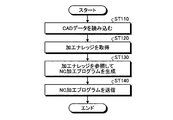
- the flowchart which shows the procedure of the NC machining program production
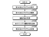
- the flowchart which shows the procedure of the NC process program edit process in the NC process program production
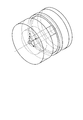
- the perspective view which shows an example of the solid model of the finishing shape represented by CAD data in Embodiment 1 of this invention The perspective view which shows an example of the raw material shape containing the process finishing shape represented by CAD data in Embodiment 1 of this invention
- the figure which shows the turning cross-section shape of the turning bar material process concerning Embodiment 1 of this invention The figure which shows the turning cross-section shape of the turning bar material process concerning Embodiment 1 of this invention.
- the figure which shows an example of the incision point of a turning bar process concerning Embodiment 1 of this invention, a process start point, and a process end point The figure which shows an example of the incision point of a turning bar process concerning Embodiment 1 of this invention, a process start point, and a process end point
- the figure which shows the turning cross-section shape of the turning bar material process concerning Embodiment 1 of this invention The figure which shows the turning cross-section shape of the turning bar material process concerning Embodiment 1 of this invention.
- the figure which shows an example of the cut point of the turning bar front process concerning Embodiment 1 of this invention, a process start point, and a process end point The figure which shows an example of the cut point of the turning bar grooving process concerning Embodiment 1 of this invention, a process start point, and a process end point
- FIG. 1 is a block diagram illustrating a configuration example of a numerical control device 1 including an NC machining program generation device 40 according to the first embodiment of the present invention.
- the NC machining program generation device 40 constitutes the numerical control device 1 together with the dialogue operation processing unit 10, the display unit 20, and the instruction input unit 30.
- the numerical control device 1 is mounted on or connected to a numerical control machine tool (not shown), and numerically controls the operation of the numerical control machine tool by an NC machining program.
- the dialogue operation processing unit 10 is an interface unit between the numerical control device 1 and the worker, and an interface unit between the NC machining program generation device 40 and the worker.
- the dialogue operation processing unit 10 transmits the instruction information input by the operator via the instruction input unit 30 to the NC machining program generation device 40. Further, the dialogue operation processing unit 10 displays the instruction information input by the operator via the instruction input unit 30 on the display unit 20.
- the display unit 20 is a display terminal such as a liquid crystal monitor, and displays the CAD data 100, the NC machining program, and instruction information input by the operator via the instruction input unit 30. Further, the display unit 20 displays various types of information related to processing performed by the numerical control device 1 and the NC machining program generation device 40.
- the instruction input unit 30 includes input devices such as a mouse and a keyboard, receives instruction information from the worker, and transmits the instruction information to the dialogue operation processing unit 10.
- the NC machining program generation device 40 is used to cut out the shape of the cut product represented by the CAD data 100 input to the NC machining program generation device 40 from the outside of the numerical control device 1 from the workpiece by cutting. NC processing program to be generated is generated.
- the NC machining program is a numerical machining program for operating an NC machine tool (not shown).
- the numerical controller 1 controls the NC machine tool according to the NC machining program, and cuts the workpiece to produce a cut product.
- the NC machining program generation device 40 includes a machining shape data input unit 41, a machining shape data storage unit 42, an NC machining program generation unit 43, an NC machining program storage unit 44, an NC machining program editing unit 45, and machining knowledge.
- storage part 47, and the process knowledge reflection part 48 are provided. Each component of the NC machining program generation device 40 can transmit and receive information to and from each other.
- the machining shape data input unit 41 receives CAD data 100 that is machining shape data input to the NC machining program generation device 40 from an external device external to the numerical controller 1 and transmits the CAD data 100 to the machining shape data storage unit 42.
- the machining shape data includes information on the finished shape of the machined product and information on the material of the material.
- the finished shape is a three-dimensional shape that must be finished by cutting to obtain a cut product.
- the material is a workpiece to be machined with the finished shape represented by the CAD data 100.
- the machining shape data is not limited to the CAD data 100.
- the machining shape data may be data that can be interpreted by the NC machining program generation device 40.
- the machining shape data storage unit 42 stores the machining shape data transmitted from the machining shape data input unit 41.
- the NC machining program generation unit 43 generates an NC machining program for cutting out the machining finished shape represented by the CAD data 100 from the material. Specifically, the NC machining program generation unit 43 refers to the machining knowledge acquired via the machining knowledge search unit 46 based on the machining shape data of the machined product, and the machining sequence and the machining method in a plurality of machining operations. To decide. Then, the NC machining program generation unit 43 generates a first NC machining program 111 that is an NC machining program for cutting a machined product from the workpiece based on the decided machining order and machining method.
- the NC machining program generation unit 43 associates the machining knowledge referred to in the generation of the first NC machining program 111 with the first NC machining program 111, and associates the first NC machining program 111 and the machining knowledge in the NC machining program storage unit 44. Send and memorize.
- the NC machining program generation unit 43 automatically generates an NC machining program for machining the machined shape of the machined product represented by the CAD data 100 from the material
- the machining knowledge is cut out from the material.
- This is a determination condition that is referred to in order to determine at least one of a material processing order and a material processing method in a plurality of cutting operations.
- the machining knowledge is a condition for designating at least one of a material processing order and a material processing method based on a dimension of a processing removal shape that is a shape to be removed in order to cut a cut product from the material. It is.
- the material processing order is the order of cutting when a plurality of different cutting processes are combined in order to cut a cut product from the material.
- the material processing method is a cutting method including a processing direction.
- the machining knowledge is updated to reflect the edited content when the operator edits the first NC machining program 111 automatically generated by the NC machining program generation unit 43 as will be described later.
- the editing knowledge reflecting the knowledge and experience of the operator is reflected and accumulated in the machining knowledge.
- the NC machining program generation unit 43 generates an NC machining program by referring to machining knowledge, so that the operator can create an NC machining program desired by the operator, similar to the case where the operator himself creates the NC machining program. It becomes possible to generate automatically automatically.
- the NC machining program storage unit 44 stores the first NC machining program 111, which is the NC machining program generated in the NC machining program generation unit 43, and the machining knowledge referred to in the generation of the first NC machining program 111 in association with each other.
- the NC machining program storage unit 44 stores a second NC machining program 112 that is an NC machining program edited by the NC machining program editing unit 45. Note that the first NC machining program 111 may be updated by the second NC machining program 112.
- the NC machining program editing unit 45 reads the first NC machining program 111 and the machining knowledge associated with the first NC machining program 111 from the NC machining program storage unit 44, and transmits the first NC machining program 111 to the dialogue operation processing unit 10.
- the NC machining program editing unit 45 edits the first NC machining program 111 based on editing instruction information input by the operator from the instruction input unit 30 to generate a second NC machining program 112.
- the NC machining program editing unit 45 transmits the generated second NC machining program 112 to the NC machining program storage unit 44 for storage. Further, the NC machining program editing unit 45 transmits the first NC machining program 111, the machining knowledge associated with the first NC machining program 111, and the second NC machining program 112 to the machining knowledge reflecting unit 48.
- the machining knowledge storage unit 47 stores machining knowledge corresponding to a machined product for each machined product. That is, the machining knowledge storage unit 47 stores machining knowledge for each machining shape data. In other words, the machining knowledge storage unit 47 stores machining knowledge for each combination of information on the finished shape of a machined product and information on the material material. Yes.
- the machining knowledge stored in the machining knowledge storage unit 47 is updated by the machining knowledge reflection unit 48. Some machining knowledge is stored when the numerical controller 1 is shipped. Further, machining knowledge newly generated by the machining knowledge reflecting unit 48 is also stored in the machining knowledge storage unit 47.
- the machining knowledge search unit 46 searches for a plurality of different machining knowledge stored in the machining knowledge storage unit 47 in response to a request from the NC machining program generation unit 43, and obtains machining knowledge corresponding to the CAD data 100. get.
- the processing knowledge has a one-to-one correspondence with the finished shape of the cut product.
- the machining knowledge is assigned a common management number to the machined product and corresponds to the machined product on a one-to-one basis.
- the machining knowledge corresponds one-to-one with respect to a combination of a machining finish shape represented by, for example, CAD data 100 and a material material.
- the machining knowledge search unit 46 can search for a desired machining knowledge designated by the NC machining program generation unit 43 using the management number or information on the machining finish shape and the material information as search conditions. it can.
- the machining knowledge reflecting unit 48 reflects the edited content for the first NC machining program 111 in the machining knowledge stored in the machining knowledge storage unit 47.
- the machining knowledge reflecting unit 48 acquires the edited content for the first NC machining program 111 by comparing the first NC machining program 111 and the second NC machining program 112. Then, the machining knowledge reflecting unit 48 creates reflected machining knowledge reflecting the edited contents in the machining knowledge associated with the first NC machining program 111, transmits the reflected machining knowledge to the machining knowledge storage unit 47, and updates the machining knowledge with the reflected machining knowledge.
- the processing of the NC machining program generation device 40 according to the first embodiment is divided into (1) NC machining program generation processing and (2) NC machining program editing processing.
- (1) NC machining program generation processing and (2) NC machining program editing processing will be described.
- FIG. 2 is a flowchart showing a procedure of NC machining program generation processing in the NC machining program generation device 40 according to the first embodiment of the present invention.
- an NC machining program for cutting out a three-dimensional machining finished shape represented by the CAD data 100 from the material is generated with reference to machining knowledge corresponding to the CAD data 100.
- step ST110 the NC machining program generation unit 43 reads the CAD data 100 stored in the machining shape data storage unit 42, and the shape of a storage unit (not shown) in the NC machining program generation unit 43 is read. Store in the storage area.
- step ST120 the NC machining program generation unit 43 acquires machining knowledge corresponding to the CAD data 100 from the machining knowledge storage unit 47 via the machining knowledge search unit 46 in order to generate an NC machining program.
- step ST130 the NC machining program generation unit 43 refers to the obtained machining knowledge and generates a first NC machining program 111 that is an NC machining program.
- step ST140 the NC machining program generation unit 43 associates the machining knowledge referred to in the generation of the first NC machining program 111 with the first NC machining program 111, and associates the first NC machining program 111 and the machining knowledge with the NC machining program.
- the data is transmitted to the storage unit 44.
- the NC machining program storage unit 44 stores the first NC machining program 111 and machining knowledge.
- FIG. 3 is a flowchart showing the procedure of the NC machining program editing process in the NC machining program generating apparatus 40 according to the first embodiment of the present invention.
- the first NC machining program 111 generated by the NC machining program generation unit 43 is edited.
- step ST210 the NC machining program editing unit 45 reads the first NC machining program 111 and the machining knowledge associated with the first NC machining program 111 from the NC machining program storage unit 44, and the first NC machining program 111 is read. Is transmitted to the dialogue operation processing unit 10.
- the dialogue operation processing unit 10 displays the first NC machining program 111 transmitted from the NC machining program editing unit 45 on the display unit 20 and prompts the operator to confirm the first NC machining program 111.
- the operator confirms the first NC machining program 111 and inputs edit instruction information of the first NC machining program 111 to the instruction input unit 30.
- the edit instruction information is transmitted from the instruction input unit 30 to the NC machining program editing unit 45 of the NC machining program generation device 40 via the dialogue operation processing unit 10.
- the NC machining program editing unit 45 receives the editing instruction information, edits the first NC machining program 111 based on the editing instruction information, and generates the second NC machining program 112.
- the second NC machining program 112 is an NC machining program in which the first NC machining program 111 is edited based on the editing instruction information. Then, the NC machining program editing unit 45 transmits the first NC machining program 111, the machining knowledge, and the second NC machining program 112 to the machining knowledge reflecting unit 48.
- step ST230 the machining knowledge reflecting unit 48 acquires the edited content of the second NC machining program 112, which is the edited NC machining program. That is, the machining knowledge reflecting unit 48 acquires the edited content for the first NC machining program 111 by comparing the first NC machining program 111 and the second NC machining program 112.
- the machining knowledge reflecting unit 48 reflects the edited contents in the machining knowledge associated with the first NC machining program 111, and newly creates a reflected machining knowledge.
- the machining knowledge reflecting unit 48 transmits the updated first knowledge to the machining knowledge storage unit 47 to update the machining knowledge with the reflecting machining knowledge.
- the machining knowledge storage unit 47 updates and stores the contents of the machining knowledge with the contents of the reflected machining knowledge. Thereby, the edited content is reflected in the machining knowledge stored in the machining knowledge storage unit 47.
- step ST250 the NC machining program editing unit 45 transmits the second NC machining program 112 to the NC machining program storage unit 44.
- the NC machining program storage unit 44 stores the second NC machining program 112.
- step ST250 may be performed at an arbitrary timing after step ST220.
- the editing end instruction information for ending the NC machining program editing process is input by the operator. Input to the unit 30.
- the editing end instruction information is transmitted from the instruction input unit 30 to the NC machining program editing unit 45 of the NC machining program generation device 40 via the dialogue operation processing unit 10.
- the NC machining program editing unit 45 ends the NC machining program editing process.
- FIG. 4 is a flowchart showing details of a procedure of NC machining program generation processing in the NC machining program generation unit 43 of the NC machining program generation device 40 according to the first embodiment of the present invention.
- FIG. 5 is a perspective view illustrating an example of a three-dimensional model of a finished shape represented by CAD data 100 according to Embodiment 1 of the present invention.
- FIG. 6 is a perspective view showing an example of a material shape including a processed finish shape represented by CAD data 100 according to Embodiment 1 of the present invention.
- FIG. 5 is a perspective view illustrating an example of a three-dimensional model of a finished shape represented by CAD data 100 according to Embodiment 1 of the present invention.
- FIG. 6 is a perspective view showing an example of a material shape including a processed finish shape represented by CAD data 100 according to Embodiment 1 of the present invention.
- FIG. 7 is a perspective view showing an example of a machining removal shape generated from the machining finish shape and the material shape represented by the CAD data 100 according to Embodiment 1 of the present invention.
- FIG. 8 is a diagram showing the material shape S, the turning cross-sectional shape generated from the machining shape, and the coordinate values in the first embodiment of the present invention. Below, the case where the NC processing program regarding the turning which cuts a raw material while rotating is produced is demonstrated.
- step ST310 the NC machining program generation unit 43 reads the CAD data 100 stored in the machining shape data storage unit 42, and the three-dimensional data represented by the CAD data 100 as shown in FIG.
- the machining finish shape is generated and placed at the program origin which is the machining origin of the program coordinate system.
- the Z axis is a turning axis SG which is a central axis when performing turning.
- the NC machining program generation unit 43 arranges the machining finished shape at the program origin, among the machining finished shapes, the rotation axis of the cylindrical surface or the conical surface having the maximum diameter coincides with the Z axis.
- the finished shape is moved and rotated. Further, the Z-axis direction end face of the finished machining shape moves so as to coincide with the program origin. That is, the NC machining program generation unit 43 extracts, from the CAD data 100, a cylindrical surface or a conical surface having the same turning axis SG as the turning center axis as a turning end face. Accordingly, the NC machining program generation unit 43 generates a three-dimensional machining finish shape from the CAD data 100 with the turning axis as the rotation center axis.
- step ST320 the NC machining program generation unit 43 generates a three-dimensional cylindrical shape including the finished machining shape arranged at the program origin. Then, the NC machining program generation unit 43 uses the generated cylindrical shape as a material shape and arranges it in the program coordinate system in the same manner as the finished machining shape.
- the material shape is a shape of a material that is formed by turning the finished shape by turning. That is, the NC machining program generation unit 43 generates a three-dimensional material shape based on the finished machining shape generated from the CAD data 100.
- the dimensions of the cylindrical shape including the processed finish shape can be obtained from the maximum value and the minimum value in the X-axis direction, the Y-axis direction, and the Z-axis direction in the processed finish shape.
- the dimension in the Z-axis direction is set to be larger by 2 to 3 mm than the finished work shape in accordance with the finished work shape.
- the end surface of the material shape in the Z-axis direction is disposed at a position protruding from the program origin in a direction away from the finished shape by 2 to 3 mm.
- the material shape is 150 mm for the material outer diameter, 120 mm for the material length, and S45C for the material material.
- step ST330 the NC machining program generation unit 43 generates a machining removal shape, which is a shape to be removed from the material shape by turning, from the machining finish shape and the material shape.
- the finished work shape is indicated by a broken line.
- the processed removal shape can be obtained by a difference calculation in which the solid model of the finished shape is removed from the solid model of the material shape.
- the NC machining program generation unit 43 generates a turning cross-sectional shape t, which is a cross-sectional shape of the machining removal shape, as shown in FIG.
- the turning cross-sectional shape t is a 1 ⁇ 2 turning cross-sectional shape obtained by projecting the processed removal shape onto the + XZ plane, which is limited to the + X region of the XZ plane.
- the turning cross-sectional shape t can be obtained by obtaining a cross-sectional shape by product operation of a cross-sectional model made of the XZ plane and a solid model made of a machined shape, and limiting the range as an area where X ⁇ 0.
- the turning cross-sectional shape t1 and the turning cross-sectional shape t2 which are the turning cross-sectional shapes t are generated.
- step ST350 the NC machining program generation unit 43 acquires machining knowledge corresponding to the CAD data 100 from the machining knowledge storage unit 47 via the machining knowledge search unit 46, and refers to it.
- the NC machining program generation unit 43 acquires and refers to the following machining knowledge stored in the machining knowledge storage unit 47, for example.
- the open portion is a portion exposed on the surface of the material in the turning cross-sectional shape t.
- the NC machining program generation unit 43 acquires, for example, a management number commonly assigned to the CAD data 100 and machining knowledge from the CAD data 100 and transmits it to the machining knowledge search unit 46. Thereby, the machining knowledge search unit 46 can search for a desired machining knowledge designated by the NC machining program generation unit 43 using the management number as a search condition.
- the turning end surface step is a step of performing a turning end face processing in which the protruding portion of the material end face is scraped off with a turning end face tool.
- the turning drill process is a process of performing a turning drill process in which a hole along the center axis is formed with a turning drill in a center area in a radial direction of the material.
- the turning bar material process is a process of turning a bar material by turning the outer circumference, inner circumference, front face or back face of a round bar material with a turning tool.
- the turning grooving step is a step of performing turning grooving on the outer periphery, inner periphery, front or back of a round bar material with a turning grooving tool.
- the end chamfering allowance is a machining allowance in turning end face machining.
- step ST360 the NC machining program generation unit 43 divides the turning cross-sectional shape t of the machining removal shape into a plurality of different machining processes according to the obtained machining knowledge A121, machining knowledge B122, and machining knowledge C123, and performs a turning process. Generate a shape.
- the turning shape is a turning cross-sectional shape t in each processing step when a finished shape is cut out from a material by a plurality of different processing steps.
- FIG. 9 is a diagram showing a turning cross-sectional shape SH1 of the turning end face process according to the first embodiment of the present invention.
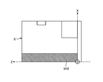
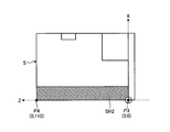
- FIG. 10 is a diagram illustrating a turning cross-sectional shape SH2 of the turning drill process according to the first embodiment of the present invention.
- FIG. 11 is a diagram showing a turning cross-sectional shape SH3 of the turning bar process according to the first embodiment of the present invention.
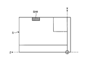
- FIG. 12 is a diagram showing a turning cross-sectional shape SH4 of the turning bar process according to the first embodiment of the present invention.
- the NC machining program generation unit 43 acquires information of the end chamfering margin: 10 mm from the turning cross-sectional shape t1. Then, the NC machining program generation unit 43 refers to the machining knowledge A121 and determines that the turning end face process is to be performed first because the end chamfering margin is not 20 mm or more, and turning from the turning cross-sectional shape t1 as shown in FIG. The turning cross-sectional shape SH1 in the end face process is divided.
- the NC machining program generation unit 43 refers to the machining knowledge A121, determines that the turning drill process is to be performed after the turning end face process, and turns the turning section of the turning drill process from the turning section shape t1 as shown in FIG.
- the shape SH2 is divided.
- the NC machining program generation unit 43 divides the turning section shape SH3 of the turning bar process from the turning section shape t1.
- the NC machining program generation unit 43 divides the turning cross-sectional shape t2 as a turning cross-sectional shape SH4 of the turning bar process as shown in FIG.
- step ST370 the NC machining program generation unit 43 assigns a turning process to the turning cross-sectional shape, which is a divided machining shape, according to the machining knowledge A121, machining knowledge B122, and machining knowledge C123, and generates a turning process.
- FIG. 13 is a diagram illustrating an example of a machining start point and a machining end point in the turning end face process according to the first embodiment of the present invention.
- FIG. 14 is a diagram illustrating an example of a machining start point and a machining end point of the turning drill process according to the first embodiment of the present invention.
- FIG. 13 is a diagram illustrating an example of a machining start point and a machining end point in the turning end face process according to the first embodiment of the present invention.
- FIG. 14 is a diagram illustrating an example of a machining start point and a machining end point of the turning drill process according to the first embodiment of the present invention.
- FIG. 15 is a diagram illustrating an example of a cut point, a machining start point, and a machining end point in the turning bar process according to the first embodiment of the present invention.
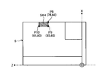
- FIG. 16 is a diagram illustrating an example of a cutting point, a machining start point, and a machining end point in the turning bar process according to the first embodiment of the present invention.
- the NC machining program generation unit 43 acquires the coordinate value of the machining start point P1 and the coordinate value of the machining end point P2 of the turning end surface process from the turning cross-sectional shape SH1 of the turning end face process, as shown in FIG. A turning end face process LC1 which is a process is generated.
- the NC machining program generation unit 43 calculates the hole diameter of the hole to be machined by the turning drill machining, the coordinate value of the machining start point P3, and the machining end point P4 from the turning cross-sectional shape SH2 of the turning drill process as shown in FIG.
- the coordinate value is acquired, and a turning drill process LC2 that is a turning drill process is generated.
- the NC machining program generation unit 43 from the turning cross-sectional shape SH3 of the turning bar process, as shown in FIG. 15, information on the longitudinal length of the open part shape: 30 mm and the horizontal direction of the open part shape Information of length: 30 mm is acquired. Then, the NC machining program generation unit 43 refers to the machining knowledge B122, and “the length in the horizontal direction of the open portion shape ⁇ the length in the vertical direction of the open portion shape” is “1.0”. The machining part of the turning bar process is determined as the outer diameter.
- the NC machining program generation unit 43 calculates the coordinate value of the cutting point P5, the coordinate value of the machining start point P6, and the coordinate value of the machining end point P7 of the turning section shape SH3 from the turning section shape SH3 of the turning bar process. Is obtained, and a turning bar outer diameter process LC3, which is a turning bar process in which the machining part has an outer diameter, is generated.
- the NC machining program generation unit 43 starts from the turning cross-sectional shape SH4 in the turning bar process, as shown in FIG. 16, information about the longitudinal length of the turning cross-sectional shape SH4: 10 mm, and the horizontal direction of the turning cross-sectional shape SH4. Length: information of 20 mm is acquired.
- the NC machining program generation unit 43 refers to the machining knowledge C123, and the longitudinal length of the turning cross-sectional shape SH4 is 10 mm or less, and the horizontal length of the turning cross-sectional shape SH4 is not 10 mm or less. Therefore, it is determined that the turning bar process is performed.
- the NC machining program generation unit 43 acquires information on the longitudinal length of the open part shape: 10 mm and information on the lateral length of the open part shape: 20 mm from the turning cross-sectional shape SH4 of the turning bar process. . Then, the NC machining program generation unit 43 refers to the machining knowledge B122, and the “horizontal length of the open portion shape ⁇ vertical length of the open portion shape” is “2.0” and “1. Since it is not “less than 0”, the processed part is determined as the outer diameter.
- the NC machining program generation unit 43 acquires the coordinate values of the cutting point P8, the machining start point P9, and the machining end point P10 of the turning cross-sectional shape SH4 from the turning cross-sectional shape SH4 of the turning bar process, and the machining part A turning bar outer diameter process LC4, which is a turning bar process in which is set as the outer diameter, is generated.
- -Turning end face process LC1 Machining start point P1 (75, -10), Machining end point P2 (0, 0) ⁇ Turning drill process LC2: Hole diameter 30mm, processing start point P3 (0, 0), processing end point P4 (0, 110) Turning rod outer diameter process LC3: cutting point P5 (75, 0), machining start point P6 (45, 0), machining end point P7 (45, 30) Turning rod outer diameter process LC4: cutting point P8 (75, 60), machining start point P9 (65, 60), machining end point P10 (65, 80)
- the NC machining program generation unit 43 automatically generates a plurality of different turning processes for cutting out the machining finished shape from the material with reference to the machining knowledge A121 to the machining knowledge C123. be able to. And, when the operator himself creates an NC machining program by automatically generating a turning process with reference to machining knowledge reflecting and accumulating editing contents reflecting the knowledge and experience of the worker, and A similar turning process desired by the operator can be automatically generated.
- the machining knowledge reflecting unit 48 acquires information of the end chamfering margin: 10 mm from the turning cross-sectional shape SH1 of the turning end surface process LC1 of the second NC machining program 112 transmitted from the NC machining program editing unit 45.
- the machining knowledge reflection unit 48 reflects the editing contents for the first NC machining program 111 and generates the reflected machining knowledge A in which the machining knowledge A121 is changed to the following conditions. Then, the machining knowledge reflecting unit 48 updates the machining knowledge A 121 stored in the machining knowledge storage unit 47 with the reflected machining knowledge A and stores it.
- the machining knowledge reflecting unit 48 receives information about the longitudinal length of the open part shape: 30 mm from the turning cross-sectional shape SH3 of the turning bar outer diameter process LC3 of the second NC machining program 112 transmitted from the NC machining program editing unit 45.
- the information on the lateral length of the open part shape: 30 mm is acquired.
- the machining site is changed to the front under the condition that “the horizontal length of the open portion shape ⁇ the vertical length of the open portion shape” is “1.0”.
- the first NC machining program 111 is edited to generate the second NC machining program 112. Therefore, the machining knowledge reflecting unit 48 generates the reflected machining knowledge B in which the machining knowledge B122 is changed to the following conditions by reflecting the editing contents for the first NC machining program 111. Then, the machining knowledge reflection unit 48 updates and stores the machining knowledge B122 stored in the machining knowledge storage unit 47 with the reflected machining knowledge B.
- Material S45C Processed portion: When “the length of the open portion shape in the horizontal direction ⁇ the length of the open portion shape in the vertical direction” is “1.0 or less”, the processed portion is the front face. When “the length in the lateral direction of the open part shape ⁇ the length in the vertical direction of the open part shape” is “greater than 1.0”, the processed portion is set as the outer diameter.
- the machining knowledge reflecting unit 48 has a vertical length of the turning cross-sectional shape SH4 of 10 mm from the turning cross-sectional shape SH4 of the turning rod outer diameter process LC4 of the second NC machining program 112 transmitted from the NC machining program editing unit 45.
- Information, information on the horizontal length of the turning cross-sectional shape SH4: 20 mm is acquired.
- the turning grooving step LC41 is performed under the condition that the longitudinal length of the turning cross-sectional shape SH4 is 10 mm and the horizontal length of the turning cross-sectional shape SH4 is 20 mm.
- the first NC machining program 111 is edited so that the second NC machining program 112 is generated. Therefore, the machining knowledge reflecting unit 48 generates reflected machining knowledge C in which the machining knowledge C123 is changed to the following conditions by reflecting the edited content of the first NC machining program 111. Then, the machining knowledge reflecting unit 48 updates and stores the machining knowledge C123 stored in the machining knowledge storage unit 47 with the reflected machining knowledge C.
- Material S45C Processing method: When the longitudinal length of the turning cross-sectional shape is “10 mm or less” and the horizontal length of the turning cross-sectional shape is “20 mm or less”, a turning grooving step is performed. When the length in the vertical direction and the length in the horizontal direction of the turning cross-sectional shape are other than the above conditions, a turning bar process is performed.
- FIG. 17 is a diagram showing a turning cross-sectional shape SH5 of the turning drill process according to the first embodiment of the present invention.
- FIG. 18 is a diagram showing a turning cross-sectional shape SH6 of the turning end face process according to the first embodiment of the present invention.
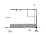
- FIG. 19 is a diagram showing a turning cross-sectional shape SH7 of the turning bar process according to the first embodiment of the present invention.
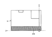
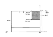
- FIG. 20 is a diagram showing a turning cross-sectional shape SH8 of the turning bar process according to the first embodiment of the present invention.
- the NC machining program generation unit 43 acquires information on the material length: 120 mm and information on the material outer diameter: 150 mm from the material shape, and acquires information on the end chamfering margin: 10 mm from the turning cross-sectional shape t1. Then, the NC machining program generation unit 43 refers to the updated machining knowledge A121, determines that the turning drill step is performed first because the end chamfering margin is 10 mm or more, and as shown in FIG. The turning cross-sectional shape SH5 of the turning drill process is divided from the shape t1.
- the NC machining program generation unit 43 refers to the updated machining knowledge A121, determines that the turning end face process is to be performed after the turning drill process, and turns the turning end face process from the turning cross-sectional shape t1 as shown in FIG.
- the turning cross-sectional shape SH6 is divided.
- the NC machining program generation unit 43 divides the turning section shape SH7 of the turning bar process from the turning section shape t1.
- the NC machining program generation unit 43 divides the turning cross-sectional shape t2 as a turning cross-sectional shape SH8 of the turning bar process as shown in FIG.
- FIG. 21 is a diagram illustrating an example of a machining start point and a machining end point of the turning drill process according to the first embodiment of the present invention.
- FIG. 22 is a diagram illustrating an example of a machining start point and a machining end point in the turning end face process according to the first embodiment of the present invention.
- FIG. 23 is a diagram illustrating an example of a cut point, a machining start point, and a machining end point in the turning bar front surface process according to the first embodiment of the present invention.
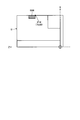
- FIG. 24 is a diagram illustrating an example of a cutting point, a processing start point, and a processing end point in the turning bar grooving step according to the first embodiment of the present invention.
- the NC machining program generation unit 43 calculates the hole diameter of the hole to be machined by the turning drill machining, the coordinate value of the machining start point P11, and the coordinate value of the machining end point P12 from the turning cross-sectional shape SH5 of the turning drill process as shown in FIG. To obtain a turning drill process LC11 which is a turning drill process.
- the NC machining program generation unit 43 acquires the coordinate value of the machining start point P13 and the coordinate value of the machining end point P14 in the turning end face process, as shown in FIG. 22, from the turning cross-sectional shape SH6 of the turning end face process. Then, a turning end face process LC12 which is a turning end face process is generated.
- the NC machining program generation unit 43 from the turning cross-sectional shape SH7 of the turning bar process, as shown in FIG. 23, information on the longitudinal length of the open part shape: 30 mm and the horizontal direction of the open part shape. Information of length: 30 mm is acquired. Then, the NC machining program generation unit 43 refers to the updated machining knowledge B122, and the “horizontal length of the open portion shape ⁇ vertical length of the open portion shape” is “1.0”. Since it is “1.0 or less”, the machining part of the turning bar process is determined as the front surface.
- the NC machining program generation unit 43 calculates the coordinate value of the cutting point P15, the coordinate value of the machining start point P16, and the coordinate value of the machining end point P17 from the turning cross-sectional shape SH7 of the turning bar process. Is obtained, and a turning bar front process LC3, which is a turning bar process with the machining part as the front, is generated.
- the NC machining program generation unit 43 starts from the turning cross-sectional shape SH8 of the turning bar process, as shown in FIG. 24, information about the longitudinal length of the turning cross-sectional shape SH8: 10 mm, and the horizontal direction of the turning cross-sectional shape SH8. Length: information of 20 mm is acquired. Then, the NC machining program generation unit 43 refers to the updated machining knowledge C123, and the vertical length of the turning cross-sectional shape SH4 is 10 mm or less, and the horizontal length of the turning cross-sectional shape SH4 is 20 mm. Since it is the following, it determines with performing a turning grooving process.
- the NC machining program generation unit 43 acquires information on the longitudinal length of the open part shape: 10 mm and information on the lateral length of the open part shape: 20 mm from the turning cross-sectional shape SH8 of the turning bar process. .
- the NC machining program generation unit 43 acquires information on the groove depth: 10 mm from the information on the longitudinal length of the open part shape: 10 mm, and information on the groove width: 20 mm from the information on the lateral length of the open part shape: 20 mm. Get information.
- the NC machining program generation unit 43 acquires the coordinate value of the machining start point P18 from the turning cross-sectional shape SH8 of the turning bar process, and generates the turning grooving process LC14.
- Turning drill process LC11 Hole diameter 30mm, processing start point P11 (0, -10), processing end point P12 (0,110)
- Turning end face process LC12 machining start point P13 (75, -10), machining end point P14 (15, 0)
- Turning bar front process LC13 cutting point P15 (75, 0), machining start point P16 (75, 30), machining end point P17 (45, 30)
- the NC machining program generation unit 43 automatically refers to the updated machining knowledge A121 to the machining knowledge C123, and automatically performs a plurality of different turning processes for cutting out the machining finished shape from the material. Can be generated. Then, the operator himself creates an NC machining program by automatically generating a turning process with reference to the updated machining knowledge reflecting and accumulating the editing contents reflecting the worker's knowledge and experience. As with the case, the turning process desired by the operator can be automatically generated.
- the updated machining knowledge may be stored in the machining knowledge storage unit 47 in association with the CAD data 100.
- CAD data 100 is associated with reflection processing knowledge A.
- the machining knowledge A 121 is updated with the reflected machining knowledge A, and the CAD data 100 is stored in the machining knowledge storage unit 47.
- the updated machining knowledge may be stored in the machining knowledge storage unit 47 in association with information accompanying the CAD data 100.
- information accompanying the CAD data 100 is associated with the reflection processing knowledge A.
- Examples of information accompanying the CAD data 100 are an image of CAD data, a part of CAD data, and the like.
- the machining knowledge A 121 is updated with the reflected machining knowledge A, and information accompanying the CAD data 100 is stored in the machining knowledge storage unit 47.
- the information accompanying CAD data 100 can be paraphrased as information accompanying the combination of information on the finished shape of a machined product and information on the material of the workpiece.
- the machining knowledge search unit 46 searches for a desired machining knowledge from the plurality of machining knowledge stored in the machining knowledge storage unit 47 using the CAD data 100 or information accompanying the CAD data 100 as a search condition. It can be acquired.
- the machining knowledge storage unit 47 may store machining knowledge separately for each NC machine tool controlled by executing the NC machining program.
- different types of NC machine tools are used.
- different optional functions are added for each NC machine tool.
- the functions of each NC machine tool are different. In this case, conditions suitable for each NC machine tool also exist in the machining knowledge.
- the NC machining program generation unit 43 generates an NC machining program with reference to machining knowledge managed separately for each NC machine tool, so that the operator himself / herself creates an NC machining program.
- An NC machining program suitable for each NC machine tool desired by an operator can be quickly and automatically generated.
- FIG. 25 is a flowchart showing a procedure of NC machining program generation processing for referring to machining knowledge of similar CAD data in the NC machining program generation device 40 according to the first embodiment of the present invention.
- a procedure of NC machining program generation processing when machining knowledge corresponding to the CAD data 100 is not stored in the machining knowledge storage unit 47 will be described.
- the updated machining knowledge stored in the machining knowledge storage unit 47 is stored in association with the CAD data 100 corresponding to the machining knowledge or information associated with the CAD data 100 corresponding to the machining knowledge. .
- step ST410 the NC machining program generation unit 43 reads the CAD data 100 stored in the machining shape data storage unit 42, and stores it in the shape storage area of a storage unit (not shown) in the NC machining program generation unit 43.
- the finished shape is placed at the program origin.
- the NC machining program generation unit 43 acquires machining knowledge corresponding to the CAD data 100 from the machining knowledge storage unit 47 via the machining knowledge search unit 46 in order to generate an NC machining program.
- the NC machining program generation unit 43 transmits the CAD data 100A read from the machining shape data storage unit 42 to the machining knowledge search unit 46, and requests acquisition of machining knowledge corresponding to the CAD data 100A.
- the machining knowledge search unit 46 uses the machining finish shape information of the machined product and the material material information included in the CAD data 100A as search conditions to obtain the desired machining knowledge specified by the NC machining program generation unit 43. Is searched in the processing knowledge storage unit 47, and it is determined whether or not there is processing knowledge corresponding to the CAD data 100A.
- Step ST420 If there is machining knowledge corresponding to the CAD data 100A, Yes in step ST420 and the process proceeds to step ST120. Steps ST120 to ST140 are the same as those in FIG.
- step ST420 the machining knowledge search unit 46 transmits information to the NC machining program generation unit 43 that there is no machining knowledge corresponding to the CAD data 100A. Then, the process proceeds to step ST430.
- the NC machining program generation unit 43 searches for similar CAD data 100B from other CAD data 100 stored in the machining knowledge storage unit 47, and determines whether there is similar CAD data 100B. To do.
- the similar CAD data 100B is the same as the material of the material included in the CAD data 100A, and the processed product shape of the machined product represented by the CAD data is represented by the CAD data 100A.
- the material of the material is the same as the material of the material included in the CAD data 100A, and the processed product shape of the machined product represented by the CAD data is represented by the CAD data 100A.
- the NC machining program generation unit 43 compares the CAD data 100A with the other CAD data 100 stored in the machining knowledge storage unit 47, and searches for CAD data having the most similar machining finish shape.
- a known technique for determining similarity by comparing image features or shape features may be used. Note that a similar range of the finished shape may be provided.
- step ST430 If there is similar CAD data 100B, Yes in step ST430, the process proceeds to step ST440. If there is no similar CAD data 100B, No in step ST430, the process proceeds to step ST460.
- step ST440 the NC machining program generation unit 43 acquires machining knowledge corresponding to the similar CAD data 100B from the machining knowledge storage unit 47 via the machining knowledge search unit 46.
- step ST450 the NC machining program generation unit 43 generates a first NC machining program 111, which is an NC machining program, with reference to machining knowledge corresponding to the similar CAD data 100B.
- step ST460 the NC machining program generation unit 43 searches for partially similar CAD data 100C from other CAD data 100 stored in the machining knowledge storage unit 47.
- the material is the same as the material included in the CAD data 100A, and a part of the finished shape of the machined product represented by the CAD data is represented by the CAD data 100A.
- the material is the same as the material included in the CAD data 100A, and a part of the finished shape of the machined product represented by the CAD data is represented by the CAD data 100A.
- the NC machining program generation unit 43 compares the CAD data 100A with other CAD data 100 stored in the machining knowledge storage unit 47, and searches for CAD data that is partially similar.
- a publicly known technique for determining similarity by comparing image features or shape features may be used. The degree of partial similarity of shapes can be arbitrarily set.
- step ST470 the NC machining program generation unit 43 acquires machining knowledge corresponding to the partially similar CAD data 100C from the machining knowledge storage unit 47 via the machining knowledge search unit 46.
- step ST480 the NC machining program generation unit 43 generates a first NC machining program 111 that is an NC machining program with reference to machining knowledge corresponding to the partially similar CAD data 100C.
- the NC machining program generation unit 43 acquires machining knowledge corresponding to the shape data of other cutting products having the same material and similar machining finish shapes from the machining knowledge storage unit 47, and obtains other A processing order and a processing method in a plurality of cutting operations are determined with reference to processing knowledge corresponding to the shape data of the cut product.
- the machining knowledge corresponding to the similar CAD data 100B can be stored in the machining knowledge storage unit 47 as the machining knowledge corresponding to the CAD data 100A.
- the NC machining program generated in step ST450 is edited by the operator, the machining knowledge can be updated by reflecting the edited contents in the machining knowledge as described above.
- the machining knowledge corresponding to the partially similar CAD data 100C can be stored in the machining knowledge storage unit 47 as the machining knowledge corresponding to the CAD data 100A.
- the NC machining program generated in step ST480 is edited by the operator, the machining knowledge can be updated by reflecting the edited contents in the machining knowledge as described above.
- the machining knowledge is updated to conditions suitable for the generation of the NC machining program of the CAD data 100A, and thereafter, the NC machining program desired by the operator is the same as the case where the operator himself creates the NC machining program. It becomes possible to generate automatically automatically.
- the machining knowledge search unit 46 stores the machining finished shape information of the cut product and the material material information included in the CAD data 100A as search conditions and is stored in the machining knowledge storage unit 47.
- the similar CAD data 100B may be searched from the CAD data associated with the updated machining knowledge or the information accompanying the CAD data 100.
- FIG. 26 is a diagram showing a hardware configuration of the NC machining program generation device 40 according to the first embodiment of the present invention.
- the hardware shown in FIG. 26 includes a processor 201 that performs arithmetic processing, a memory 202 that the processor 201 uses as a work area, a storage device 203 that stores a program for operating as a numerical control device or a program conversion device, An input device 204 that is an input interface with a person, a display device 205 that displays information to an operator, a communication device 206 having a communication function with a controlled device or other numerical control device, and other various devices, .
- the processor 201, the memory 202, the storage device 203, the input device 204, the display device 205, and the communication device 206 are connected by a data bus 207.
- the processor 201 may be a processing device, an arithmetic device, a microprocessor, a microcomputer, a CPU (Central Processing Unit), a DSP (Digital Signal Processor), or the like.
- the memory 202 is a non-volatile or volatile semiconductor such as RAM (Random Access Memory), ROM (Read Only Memory), flash memory, EPROM (Erasable Programmable ROM), or EEPROM (registered trademark) (Electrically EPROM).
- RAM Random Access Memory
- ROM Read Only Memory
- flash memory EPROM (Erasable Programmable ROM), or EEPROM (registered trademark) (Electrically EPROM).
- a memory, a magnetic disk, a flexible disk, an optical disk, a compact disk, a mini disk, a DVD (Digital Versatile Disc), and the like are
- the NC machining program generation unit 43 is realized, for example, when the processor 201 executes a program stored in the memory 202 illustrated in FIG. A plurality of processors and a plurality of memories may cooperate to realize the above function. Further, a part of the functions of the NC machining program generation unit 43 may be mounted as an electronic circuit, and the other parts may be realized using the processor 201 and the memory 202.
- the machining shape data input unit 41, the NC machining program editing unit 45, the machining knowledge search unit 46, and the machining knowledge reflection unit 48 are realized by the processor 201 executing the program stored in the memory 202 in the same manner. You may comprise. A plurality of processors and a plurality of memories may cooperate to realize the above function. Further, some of the functions of the machining shape data input unit 41, the NC machining program editing unit 45, the machining knowledge search unit 46, and the machining knowledge reflection unit 48 are mounted as an electronic circuit, and the other parts are implemented by the processor 201 and the memory. 202 may be used.
- a processor and a memory for realizing the functions of the machining shape data input unit 41, the NC machining program editing unit 45, the machining knowledge search unit 46, and the machining knowledge reflection unit 48 are processors for realizing the NC machining program generation unit 43. It may be the same as the memory, or may be a different processor and memory.
- the NC machining program generation device 40 refers to the machining knowledge in which the editing contents reflecting the knowledge and experience of the operator are reflected and accumulated based on the CAD data 100.
- the NC machining program generation device 40 By automatically generating the turning process, it is possible to automatically generate the turning process desired by the operator, similar to the case where the operator himself creates the NC machining program. Further, when the NC machining program generated by the NC machining program generation unit 43 is edited, the editing knowledge can be reflected in the machining knowledge and the content of the machining knowledge can be updated. This makes it possible to automatically generate a high-quality NC machining program that is closer to the turning process desired by the operator.
- the NC machining program generation device 40 is incorporated in the numerical control device 1 .
- the NC machining program generation device 40 is provided outside the numerical control device 1 independently. May be.
- the NC machining program in the case where the numerically controlled machine tool is a lathe has been described as an example.
- the numerically controlled machine tool is not limited to a lathe and may be another machine tool. May be.
- the configuration described in the above embodiment shows an example of the contents of the present invention, and can be combined with another known technique, and can be combined with other configurations without departing from the gist of the present invention. It is also possible to omit or change the part.
- 1 numerical control device 10 interactive operation processing unit, 20 display unit, 30 instruction input unit, 40 NC machining program generation device, 41 machining shape data input unit, 42 machining shape data storage unit, 43 NC machining program generation unit, 44 NC Machining program storage unit, 45 NC machining program editing unit, 46 machining knowledge search unit, 47 machining knowledge storage unit, 48 machining knowledge reflection unit, 100 CAD data, 111 first NC machining program, 112 second NC machining program, 121 machining knowledge A 122 processing knowledge B, 123 processing knowledge C, 201 processor, 202 memory, 203 storage device, 204 input device, 205 display device, 206 communication device, 207 data bus.
Landscapes
- Engineering & Computer Science (AREA)
- Mechanical Engineering (AREA)
- Human Computer Interaction (AREA)
- Manufacturing & Machinery (AREA)
- Physics & Mathematics (AREA)
- General Physics & Mathematics (AREA)
- Automation & Control Theory (AREA)
- Numerical Control (AREA)
Abstract
数値制御加工プログラム生成装置は、被加工物から切削加工品を削り出すための複数の切削加工を含む数値制御加工プログラムを生成する数値制御加工プログラム生成装置である。数値制御加工プログラム生成装置は、複数の切削加工の加工順序と加工方法とのうち少なくとも一方を決定するための決定条件である加工ナレッジを記憶する加工ナレッジ記憶部(47)と、切削加工品の加工仕上がり形状の情報、被加工物の材質の情報、および加工ナレッジに基づいて、複数の切削加工の加工順序と加工方法とのうち少なくとも一方を決定し、被加工物から切削加工品を削り出すための第1数値制御加工プログラムを生成するNC加工プログラム生成部(43)と、を備える。
Description
本発明は、工作機械を数値制御するための数値制御加工プログラムを生成する数値制御加工プログラム生成装置および数値制御加工プログラムの生成方法に関する。
近年、数値制御(Numerical Control:NC)工作機械の分野では、複雑且つ多彩な形状の工作物を自動加工できるようにするため、多種類の工具を刃物台に交換可能に装備して、旋削加工、穴あけ加工、フライス加工等の多様な加工工程を実施可能にする複合機械化が進められている。
特許文献1には、自動生成した加工プログラムに対してオペレータが修正した切削条件の修正内容を記憶部に記憶させて、他のオペレータが次に同様の加工プログラムを作成する際に、修正後の切削条件を再利用可能な数値制御加工プログラム作成装置が開示されている。
しかしながら、上記特許文献1の数値制御加工プログラム作成装置では、再利用可能とされているのは、加工対象素材を回転させる主軸の回転数、回転工具と加工対象素材との間の相対的切削送り量および切り上げといった切削条件だけであり、加工順序および加工方法に関しては加工プログラムを自動生成することができなかった。
本発明は、上記に鑑みてなされたものであって、加工順序および加工方法のうち少なくとも一方に関して加工プログラムを自動生成することができる数値制御加工プログラム生成装置を得ることを目的とする。
上述した課題を解決し、目的を達成するために、本発明にかかる数値制御加工プログラム生成装置は、被加工物から切削加工品を削り出すための複数の切削加工を含む数値制御加工プログラムを生成する数値制御加工プログラム生成装置である。数値制御加工プログラム生成装置は、複数の切削加工の加工順序と加工方法とのうち少なくとも一方を決定するための決定条件である加工ナレッジを記憶する加工ナレッジ記憶部と、切削加工品の加工仕上がり形状の情報、被加工物の材質の情報、および加工ナレッジに基づいて、複数の切削加工の加工順序と加工方法とのうち少なくとも一方を決定し、被加工物から切削加工品を削り出すための第1数値制御加工プログラムを生成する数値制御加工プログラム生成部と、を備える。
本発明によれば、加工順序および加工方法のうち少なくとも一方に関して加工プログラムを自動生成することができる数値制御加工プログラム生成装置が得られる、という効果を奏する。
以下に、本発明の実施の形態にかかる数値制御加工プログラム生成装置および数値制御加工プログラムの生成方法を図面に基づいて詳細に説明する。なお、この実施の形態によりこの発明が限定されるものではない。
実施の形態1.
図1は、本発明の実施の形態1にかかるNC加工プログラム生成装置40を含む数値制御装置1の構成例を示すブロック図である。図1に示すように、NC加工プログラム生成装置40は、対話操作処理部10と、表示部20と、指示入力部30とともに数値制御装置1を構成する。数値制御装置1は、不図示の数値制御工作機械に搭載され、または接続されて、NC加工プログラムにより数値制御工作機械の動作を数値制御する。
図1は、本発明の実施の形態1にかかるNC加工プログラム生成装置40を含む数値制御装置1の構成例を示すブロック図である。図1に示すように、NC加工プログラム生成装置40は、対話操作処理部10と、表示部20と、指示入力部30とともに数値制御装置1を構成する。数値制御装置1は、不図示の数値制御工作機械に搭載され、または接続されて、NC加工プログラムにより数値制御工作機械の動作を数値制御する。
対話操作処理部10は、数値制御装置1と作業者との間のインタフェース部であるとともに、NC加工プログラム生成装置40と作業者との間のインタフェース部である。対話操作処理部10は、作業者が指示入力部30を介して入力した指示情報をNC加工プログラム生成装置40に送信する。また、対話操作処理部10は、作業者が指示入力部30を介して入力した指示情報を表示部20に表示する。
表示部20は、液晶モニタなどの表示端末であり、CADデータ100、NC加工プログラム、作業者が指示入力部30を介して入力した指示情報を表示する。また、表示部20は、数値制御装置1およびNC加工プログラム生成装置40で行われる処理に関する各種の情報を表示する。
指示入力部30は、マウスおよびキーボード等の入力機器を備えて構成され、作業者からの指示情報を受け付けて、対話操作処理部10に送信する。
NC加工プログラム生成装置40は、数値制御装置1の外部からNC加工プログラム生成装置40に入力されるCADデータ100で表される切削加工品の形状を切削加工により被加工物から削り出すために用いられるNC加工プログラムを生成する。NC加工プログラムは、不図示のNC工作機械を動作させるための数値加工プログラムである。また、数値制御装置1は、NC加工プログラムに従ってNC工作機械を制御し、被加工物を切削加工して切削加工品を作製する。
NC加工プログラム生成装置40は、加工形状データ入力部41と、加工形状データ記憶部42と、NC加工プログラム生成部43と、NC加工プログラム記憶部44と、NC加工プログラム編集部45と、加工ナレッジ探索部46と、加工ナレッジ記憶部47と、加工ナレッジ反映部48と、を備える。NC加工プログラム生成装置40の各構成部は、互いに情報の送受信が可能とされている。
加工形状データ入力部41は、数値制御装置1の外部の外部装置からNC加工プログラム生成装置40に入力される加工形状データであるCADデータ100を受け付けて、加工形状データ記憶部42に送信する。加工形状データは、切削加工品の加工仕上がり形状の情報および素材の材質の情報を含む。加工仕上がり形状は、切削加工品を得るために切削加工により仕上げなければならない3次元形状である。素材は、CADデータ100で表される加工仕上がり形状が削り出される被加工物である。ただし、加工形状データはCADデータ100に限定されない。加工形状データは、NC加工プログラム生成装置40において解釈可能なデータであればよい。
加工形状データ記憶部42は、加工形状データ入力部41から送信された加工形状データを記憶する。
NC加工プログラム生成部43は、CADデータ100で表される加工仕上がり形状を素材から削り出すためのNC加工プログラムを生成する。詳細には、NC加工プログラム生成部43は、切削加工品の加工形状データに基づいて、加工ナレッジ探索部46を介して取得した加工ナレッジを参照して複数の切削加工における加工順序と加工方法とを決定する。そして、NC加工プログラム生成部43は、決定した加工順序と加工方法に基づいて、被加工物から切削加工品を削り出すためのNC加工プログラムである第1NC加工プログラム111を生成する。また、NC加工プログラム生成部43は、第1NC加工プログラム111の生成において参照した加工ナレッジと第1NC加工プログラム111とを関連付けて、第1NC加工プログラム111と加工ナレッジとをNC加工プログラム記憶部44に送信して記憶させる。
加工ナレッジは、CADデータ100で表される切削加工品の加工仕上がり形状を素材から削り出すためのNC加工プログラムをNC加工プログラム生成部43が自動生成する際に、素材から切削加工品を削り出すための複数の切削加工における素材の加工順序と素材の加工方法とのうち少なくとも一方を決定するために参照される決定条件である。具体的には、加工ナレッジは、素材から切削加工品を削り出すために除去する形状である加工除去形状の寸法に基づいて素材の加工順序と素材の加工方法とのうち少なくとも一方を指定する条件である。素材の加工順序は、素材から切削加工品を削り出すために複数の異なる切削加工が組み合わされる場合における切削加工の順序である。素材の加工方法は、加工方向を含む、切削加工法である。
加工ナレッジは、後述するようにNC加工プログラム生成部43において自動生成された第1NC加工プログラム111を作業者が編集した場合に、編集内容が反映されて更新される。これにより、加工ナレッジには、作業者の知識および経験が反映された編集内容が反映および蓄積される。このため、NC加工プログラム生成部43が、加工ナレッジを参照してNC加工プログラムを生成することにより、作業者自身がNC加工プログラムを作製した場合と同様の、作業者が所望するNC加工プログラムを迅速に自動生成することが可能となる。
NC加工プログラム記憶部44は、NC加工プログラム生成部43において生成されたNC加工プログラムである第1NC加工プログラム111と、第1NC加工プログラム111の生成において参照した加工ナレッジとを、関連付けて記憶する。また、NC加工プログラム記憶部44は、NC加工プログラム編集部45において編集されたNC加工プログラムである第2NC加工プログラム112を記憶する。なお、第1NC加工プログラム111は、第2NC加工プログラム112によって更新されてもよい。
NC加工プログラム編集部45は、第1NC加工プログラム111および第1NC加工プログラム111に関連付けられた加工ナレッジをNC加工プログラム記憶部44から読み込み、第1NC加工プログラム111を対話操作処理部10に送信する。NC加工プログラム編集部45は、第1NC加工プログラム111を作業者が指示入力部30から入力する編集指示情報に基づいて編集して、第2NC加工プログラム112を生成する。NC加工プログラム編集部45は、生成した第2NC加工プログラム112をNC加工プログラム記憶部44に送信して記憶させる。また、NC加工プログラム編集部45は、第1NC加工プログラム111と、第1NC加工プログラム111に関連付けられた加工ナレッジと、第2NC加工プログラム112とを加工ナレッジ反映部48に送信する。
加工ナレッジ記憶部47は、切削加工品に対応した加工ナレッジを切削加工品毎に記憶する。すなわち、加工ナレッジ記憶部47は、加工形状データ毎に加工ナレッジを記憶しており、換言すると切削加工品の加工仕上がり形状の情報および素材の材質の情報との組み合わせ毎に加工ナレッジを記憶している。加工ナレッジ記憶部47に記憶される加工ナレッジは、加工ナレッジ反映部48により更新される。一部の加工ナレッジは、数値制御装置1の出荷時に記憶されている。また、加工ナレッジ反映部48で新たに生成された加工ナレッジも、加工ナレッジ記憶部47に記憶される。
加工ナレッジ探索部46は、NC加工プログラム生成部43からの要求に対応して、加工ナレッジ記憶部47に記憶されている複数の異なる加工ナレッジを探索して、CADデータ100に対応する加工ナレッジを取得する。加工ナレッジは、切削加工品の加工仕上がり形状と1対1で対応している。加工ナレッジは、たとえば切削加工品と共通の管理番号を付与されることにより切削加工品と1対1で対応する。また、加工ナレッジは、たとえばCADデータ100で表される加工仕上がり形状と素材の材質との組み合わせに対して、1対1で対応する。これにより、加工ナレッジ探索部46は、管理番号、または加工仕上がり形状の情報と素材の材質との情報を探索条件として、NC加工プログラム生成部43から指定された所望の加工ナレッジを探索することができる。
加工ナレッジ反映部48は、加工ナレッジ記憶部47に記憶されている加工ナレッジに、第1NC加工プログラム111に対する編集内容を反映させる。加工ナレッジ反映部48は、第1NC加工プログラム111と第2NC加工プログラム112とを比較することにより、第1NC加工プログラム111に対する編集内容を取得する。そして、加工ナレッジ反映部48は、第1NC加工プログラム111に関連付けられた加工ナレッジに編集内容を反映した反映加工ナレッジを作成し、加工ナレッジ記憶部47に送信して加工ナレッジを反映加工ナレッジで更新させる。
本実施の形態1にかかるNC加工プログラム生成装置40の処理は、(1)NC加工プログラム生成処理と、(2)NC加工プログラム編集処理とに区分される。まず、(1)NC加工プログラム生成処理と(2)NC加工プログラム編集処理との処理フローの概要について説明する。
(1)NC加工プログラム生成処理
図2は、本発明の実施の形態1にかかるNC加工プログラム生成装置40におけるNC加工プログラム生成処理の手順を示すフローチャートである。NC加工プログラム生成処理では、CADデータ100に対応する加工ナレッジを参照して、CADデータ100で表される3次元の加工仕上がり形状を素材から削り出すためのNC加工プログラムが生成される。
図2は、本発明の実施の形態1にかかるNC加工プログラム生成装置40におけるNC加工プログラム生成処理の手順を示すフローチャートである。NC加工プログラム生成処理では、CADデータ100に対応する加工ナレッジを参照して、CADデータ100で表される3次元の加工仕上がり形状を素材から削り出すためのNC加工プログラムが生成される。
NC加工プログラム生成処理では、ステップST110においてNC加工プログラム生成部43が、加工形状データ記憶部42に記憶されているCADデータ100を読み込み、NC加工プログラム生成部43内の不図示の記憶部の形状記憶領域に格納する。
次に、ステップST120においてNC加工プログラム生成部43が、NC加工プログラムを生成するために、CADデータ100に対応する加工ナレッジを、加工ナレッジ探索部46を介して加工ナレッジ記憶部47から取得する。
次に、ステップST130においてNC加工プログラム生成部43は、取得した加工ナレッジを参照してNC加工プログラムである第1NC加工プログラム111を生成する。
次に、ステップST140においてNC加工プログラム生成部43は、第1NC加工プログラム111の生成において参照した加工ナレッジと第1NC加工プログラム111とを関連付けて、第1NC加工プログラム111と加工ナレッジとをNC加工プログラム記憶部44に送信する。NC加工プログラム記憶部44は、第1NC加工プログラム111と加工ナレッジとを記憶する。
(2)NC加工プログラム編集処理
図3は、本発明の実施の形態1にかかるNC加工プログラム生成装置40におけるNC加工プログラム編集処理の手順を示すフローチャートである。NC加工プログラム編集処理では、NC加工プログラム生成部43で生成された第1NC加工プログラム111の編集が行われる。
図3は、本発明の実施の形態1にかかるNC加工プログラム生成装置40におけるNC加工プログラム編集処理の手順を示すフローチャートである。NC加工プログラム編集処理では、NC加工プログラム生成部43で生成された第1NC加工プログラム111の編集が行われる。
NC加工プログラム編集処理では、ステップST210においてNC加工プログラム編集部45が、第1NC加工プログラム111および第1NC加工プログラム111に関連付けられた加工ナレッジをNC加工プログラム記憶部44から読み込み、第1NC加工プログラム111を対話操作処理部10に送信する。対話操作処理部10は、NC加工プログラム編集部45から送信された第1NC加工プログラム111を表示部20に表示させて、作業者に第1NC加工プログラム111の確認を促す。
第1NC加工プログラム111が表示部20に表示されると、作業者が第1NC加工プログラム111を確認し、第1NC加工プログラム111の編集指示情報を指示入力部30に入力する。編集指示情報は、指示入力部30から対話操作処理部10を介してNC加工プログラム生成装置40のNC加工プログラム編集部45に送信される。
次に、ステップST220においてNC加工プログラム編集部45が、編集指示情報を受信し、編集指示情報に基づいて第1NC加工プログラム111を編集して、第2NC加工プログラム112を生成する。第2NC加工プログラム112は、第1NC加工プログラム111が編集指示情報に基づいて編集されたNC加工プログラムである。そして、NC加工プログラム編集部45は、第1NC加工プログラム111と、加工ナレッジと、第2NC加工プログラム112とを加工ナレッジ反映部48に送信する。
次に、ステップST230において加工ナレッジ反映部48は、編集されたNC加工プログラムである第2NC加工プログラム112の編集内容を取得する。すなわち、加工ナレッジ反映部48は、第1NC加工プログラム111と第2NC加工プログラム112とを比較することにより、第1NC加工プログラム111に対する編集内容を取得する。
次に、ステップST240において加工ナレッジ反映部48が、第1NC加工プログラム111に関連付けられた加工ナレッジに編集内容を反映して、新たに反映加工ナレッジを作成する。加工ナレッジ反映部48は、更新第1ナレッジを加工ナレッジ記憶部47に送信して、加工ナレッジを反映加工ナレッジで更新させる。加工ナレッジ記憶部47は、反映加工ナレッジを受信すると、加工ナレッジの内容を反映加工ナレッジの内容で更新して記憶する。これにより、加工ナレッジ記憶部47に記憶されている加工ナレッジに編集内容が反映される。
次に、ステップST250においてNC加工プログラム編集部45が、第2NC加工プログラム112をNC加工プログラム記憶部44に送信する。NC加工プログラム記憶部44は、第2NC加工プログラム112を記憶する。
以上の処理が行われることにより、第1NC加工プログラム111に対するNC加工プログラム編集処理および加工ナレッジの更新処理が終了する。なお、ステップST250は、ステップST220後の任意のタイミングで行われればよい。
また、ステップST210において表示部20に表示された第1NC加工プログラム111に対して編集する必要が無い場合には、NC加工プログラム編集処理を終了する旨の編集終了指示情報が、作業者により指示入力部30に入力される。編集終了指示情報は、指示入力部30から対話操作処理部10を介してNC加工プログラム生成装置40のNC加工プログラム編集部45に送信される。NC加工プログラム編集部45は、編集終了指示情報を受信すると、NC加工プログラム編集処理を終了する。
次に、NC加工プログラム生成部43におけるNC加工プログラム生成処理の詳細について図4を参照して詳細に説明する。図4は、本発明の実施の形態1にかかるNC加工プログラム生成装置40のNC加工プログラム生成部43におけるNC加工プログラム生成処理の手順の詳細を示すフローチャートである。図5は、本発明の実施の形態1におけるCADデータ100で表される加工仕上がり形状の立体モデルの一例を示す斜視図である。図6は、本発明の実施の形態1におけるCADデータ100で表される加工仕上がり形状を包含する素材形状の一例を示す斜視図である。図7は、本発明の実施の形態1におけるCADデータ100で表される加工仕上がり形状と素材形状とから生成された加工除去形状の一例を示す斜視図である。図8は、本発明の実施の形態1における素材形状S、加工形状から生成された旋削断面形状および座標値を示す図である。以下では、素材を回転させながら削る旋削加工に関するNC加工プログラムを作成する場合について説明する。
NC加工プログラム生成処理では、ステップST310においてNC加工プログラム生成部43が、加工形状データ記憶部42に記憶されているCADデータ100を読み込み、図5に示すようにCADデータ100で表される3次元の加工仕上がり形状を生成して、プログラム座標系の加工原点であるプログラム原点に配置する。プログラム座標系においては、XYZ軸のうち、Z軸を、旋削加工を行う際の中心軸である旋削軸SGとする。
NC加工プログラム生成部43は、加工仕上がり形状をプログラム原点に配置する際、加工仕上がり形状のうち、直径が最大となる円筒面の回転軸または円錐面の回転軸がZ軸に一致するように、加工仕上がり形状を移動および回転させて配置する。また、加工仕上がり形状のZ軸方向の端面がプログラム原点に一致するように移動する。すなわち、NC加工プログラム生成部43は、CADデータ100から旋削軸SGと回転中心軸を同一とする円柱面または円錐面を旋削端面として抽出する。したがって、NC加工プログラム生成部43は、CADデータ100から、旋削軸を回転中心軸とする3次元の加工仕上がり形状を生成する。
次に、ステップST320においてNC加工プログラム生成部43は、図6に示すように、プログラム原点に配置された加工仕上がり形状を包含する3次元の円柱形状を生成する。そして、NC加工プログラム生成部43は、生成した円柱形状を素材形状として、加工仕上がり形状と同様にプログラム座標系に配置する。素材形状は、加工仕上がり形状を旋削加工により削り出す素材の形状である。すなわち、NC加工プログラム生成部43は、CADデータ100から生成した加工仕上がり形状を基に、3次元の素材形状を生成する。
加工仕上がり形状を包含する円柱形状の寸法は、加工仕上がり形状におけるX軸方向、Y軸方向およびZ軸方向における各々の最大値と最小値とから求めることができる。ただし、素材形状は、旋削端面加工を行うため、加工仕上がり形状に合わせて、Z軸方向の寸法が加工仕上がり形状よりも2mmから3mmずつ大きい寸法とされる。また、素材形状のZ軸方向の端面は、プログラム原点から2mmから3mmだけ加工仕上がり形状から離間する方向にはみ出した位置に配置される。ここでは、素材形状は、素材外径を150mm、素材長さを120mm、素材材質をS45Cとする。
次に、ステップST330においてNC加工プログラム生成部43は、図7に示すように、素材形状から旋削加工により除去する形状である加工除去形状を、加工仕上がり形状と素材形状とから生成する。図7においては、加工仕上がり形状を破線で示している。加工除去形状は、素材形状のソリッドモデルから加工仕上がり形状のソリッドモデルを引き去る差演算により求めることができる。
次に、ステップST340において、NC加工プログラム生成部43は、図8に示すように、加工除去形状の断面形状である旋削断面形状tを生成する。旋削断面形状tは、図8に示すように、加工除去形状をXZ平面のうち+Xの領域のみに限定した+XZ平面に投影して得られる1/2旋削断面形状である。旋削断面形状tは、XZ平面からなる断面モデルと加工形状からなるソリッドモデルとの積演算により断面形状を求め、X≧0の領域として範囲を限定することにより、求めることができる。これにより、図8に示すように、旋削断面形状tである旋削断面形状t1および旋削断面形状t2が生成される。
次に、ステップST350においてNC加工プログラム生成部43が、CADデータ100に対応する加工ナレッジを、加工ナレッジ探索部46を介して加工ナレッジ記憶部47から取得し、参照する。NC加工プログラム生成部43は、たとえば加工ナレッジ記憶部47に記憶されている以下の加工ナレッジを取得して参照する。
(加工ナレッジA121)
素材材質:S45C
加工順序:端面取り代が20mm以上である場合は旋削ドリル工程を先に行い、その後に旋削端面工程を行う。端面取り代が前記条件以外の場合は、旋削端面工程を先に行い、その後に旋削ドリル工程を行う。
(加工ナレッジB122)
素材材質:S45C
加工部位:「開放部形状の横方向の長さ÷開放部形状の縦方向の長さ」が「1未満」の場合は加工部位を正面とする。「開放部形状の横方向の長さ÷開放部形状の縦方向の長さ」が「1以上」の場合は加工部位を外径とする。開放部は、旋削断面形状tにおいて素材の表面に露出している部位である。
(加工ナレッジC123)
素材材質:S45C
加工方法:旋削断面形状の縦方向の長さが10mm以下、且つ旋削断面形状の横方向の長さが10mm以下である場合は、旋削溝入れ工程を行う。旋削断面形状の縦方向の長さおよび横方向の長さが前記条件以外の場合は、旋削棒材工程を行う。
素材材質:S45C
加工順序:端面取り代が20mm以上である場合は旋削ドリル工程を先に行い、その後に旋削端面工程を行う。端面取り代が前記条件以外の場合は、旋削端面工程を先に行い、その後に旋削ドリル工程を行う。
(加工ナレッジB122)
素材材質:S45C
加工部位:「開放部形状の横方向の長さ÷開放部形状の縦方向の長さ」が「1未満」の場合は加工部位を正面とする。「開放部形状の横方向の長さ÷開放部形状の縦方向の長さ」が「1以上」の場合は加工部位を外径とする。開放部は、旋削断面形状tにおいて素材の表面に露出している部位である。
(加工ナレッジC123)
素材材質:S45C
加工方法:旋削断面形状の縦方向の長さが10mm以下、且つ旋削断面形状の横方向の長さが10mm以下である場合は、旋削溝入れ工程を行う。旋削断面形状の縦方向の長さおよび横方向の長さが前記条件以外の場合は、旋削棒材工程を行う。
NC加工プログラム生成部43は、たとえばCADデータ100と加工ナレッジとに共通に付与された管理番号をCADデータ100から取得して加工ナレッジ探索部46に送信する。これにより、加工ナレッジ探索部46は、管理番号を探索条件として、NC加工プログラム生成部43から指定された所望の加工ナレッジを探索することができる。
ここで、旋削端面工程とは、素材端面の突き出し部を、旋削端面工具で削り落とす旋削端面加工を行う工程である。旋削ドリル工程とは、素材における半径方向の中心領域に旋削ドリルで中心軸に沿った穴をあける旋削ドリル加工を行う工程である。旋削棒材工程とは、旋削工具で丸棒素材の外周、内周、正面または背面を旋削する旋削棒材加工を行う工程である。旋削溝入れ工程とは、丸棒素材の外周、内周、正面または背面に、旋削溝入れ工具で溝加工を行う旋削溝入れ加工を行う工程である。端面取り代は、旋削端面加工での削り代である。
次に、ステップST360においてNC加工プログラム生成部43は、取得した加工ナレッジA121、加工ナレッジB122および加工ナレッジC123に従って加工除去形状の旋削断面形状tを複数の異なる加工工程毎に分割して、旋削加工形状を生成する。旋削加工形状は、複数の異なる加工工程により素材から加工仕上がり形状を削り出す場合の各加工工程における旋削断面形状tである。
以下、旋削断面形状tの分割手順について具体的に説明する。図9は、本発明の実施の形態1にかかる旋削端面工程の旋削断面形状SH1を示す図である。図10は、本発明の実施の形態1にかかる旋削ドリル工程の旋削断面形状SH2を示す図である。図11は、本発明の実施の形態1にかかる旋削棒材工程の旋削断面形状SH3を示す図である。図12は、本発明の実施の形態1にかかる旋削棒材工程の旋削断面形状SH4を示す図である。
NC加工プログラム生成部43は、旋削断面形状t1から端面取り代:10mmの情報を取得する。そして、NC加工プログラム生成部43は、加工ナレッジA121を参照し、端面取り代が20mm以上でないことから旋削端面工程を先に行うと判定して、図9に示すように旋削断面形状t1から旋削端面工程の旋削断面形状SH1を分割する。
次に、NC加工プログラム生成部43は、加工ナレッジA121を参照し、旋削端面工程の後に旋削ドリル工程を行うと判定して、図10に示すように旋削断面形状t1から旋削ドリル工程の旋削断面形状SH2を分割する。
次に、NC加工プログラム生成部43は、図11に示すように旋削断面形状t1から旋削棒材工程の旋削断面形状SH3を分割する。次に、NC加工プログラム生成部43は、図12に示すように旋削断面形状t2を旋削棒材工程の旋削断面形状SH4として分割する。
次に、ステップST370においてNC加工プログラム生成部43は、分割した加工形状である旋削断面形状に、加工ナレッジA121、加工ナレッジB122および加工ナレッジC123に従って旋削加工工程を割り当て、旋削加工工程を生成する。図13は、本発明の実施の形態1にかかる旋削端面工程の加工開始点と加工終了点との一例を示す図である。図14は、本発明の実施の形態1にかかる旋削ドリル工程の加工開始点と加工終了点との一例を示す図である。図15は、本発明の実施の形態1にかかる旋削棒材工程の切り込み点と加工開始点と加工終了点との一例を示す図である。図16は、本発明の実施の形態1にかかる旋削棒材工程の切り込み点と加工開始点と加工終了点との一例を示す図である。
NC加工プログラム生成部43は、旋削端面工程の旋削断面形状SH1から、図13に示すように旋削端面工程の加工開始点P1の座標値と加工終了点P2の座標値とを取得し、旋削端面工程である旋削端面工程LC1を生成する。
次に、NC加工プログラム生成部43は、旋削ドリル工程の旋削断面形状SH2から、図14に示すように旋削ドリル加工で加工する孔の孔径と加工開始点P3の座標値と加工終了点P4の座標値とを取得し、旋削ドリル工程である旋削ドリル工程LC2を生成する。
次に、NC加工プログラム生成部43は、旋削棒材工程の旋削断面形状SH3から、図15に示すように開放部形状の縦方向の長さ:30mmの情報と、開放部形状の横方向の長さ:30mmの情報とを取得する。そして、NC加工プログラム生成部43は、加工ナレッジB122を参照して、「開放部形状の横方向の長さ÷開放部形状の縦方向の長さ」が「1.0」であることから、旋削棒材工程の加工部位を外径と判定する。次に、NC加工プログラム生成部43は、旋削棒材工程の旋削断面形状SH3から、旋削断面形状SH3の切り込み点P5の座標値と加工開始点P6の座標値と加工終了点P7の座標値とを取得し、加工部位が外径とされた旋削棒材工程である旋削棒材外径工程LC3を生成する。
次に、NC加工プログラム生成部43は、旋削棒材工程の旋削断面形状SH4から、図16に示すように旋削断面形状SH4の縦方向の長さ:10mmの情報、旋削断面形状SH4の横方向の長さ:20mmの情報を取得する。そして、NC加工プログラム生成部43は、加工ナレッジC123を参照して、旋削断面形状SH4の縦方向の長さが10mm以下であり、旋削断面形状SH4の横方向の長さが10mm以下ではないことから、旋削棒材工程を行うと判定する。
次に、NC加工プログラム生成部43は、旋削棒材工程の旋削断面形状SH4から、開放部形状の縦方向長さ:10mmの情報、開放部形状の横方向長さ:20mmの情報を取得する。そして、NC加工プログラム生成部43は、加工ナレッジB122を参照して、「開放部形状の横方向の長さ÷開放部形状の縦方向の長さ」が「2.0」であり「1.0未満」でないことから、加工部位を外径と判定する。次に、NC加工プログラム生成部43は、旋削棒材工程の旋削断面形状SH4から、旋削断面形状SH4の切り込み点P8と加工開始点P9と加工終了点P10の座標値を取得して、加工部位が外径とされた旋削棒材工程である旋削棒材外径工程LC4を生成する。
以下に、NC加工プログラム生成部43において生成された旋削加工工程の内容を示す。
・旋削端面工程LC1:加工開始点P1(75,-10)、加工終了点P2(0,0)
・旋削ドリル工程LC2:孔径30mm、加工開始点P3(0,0)、加工終了点P4(0,110)
・旋削棒材外径工程LC3:切り込み点P5(75,0)、加工開始点P6(45,0)、加工終了点P7(45,30)
・旋削棒材外径工程LC4:切り込み点P8(75,60)、加工開始点P9(65,60)、加工終了点P10(65,80)
・旋削端面工程LC1:加工開始点P1(75,-10)、加工終了点P2(0,0)
・旋削ドリル工程LC2:孔径30mm、加工開始点P3(0,0)、加工終了点P4(0,110)
・旋削棒材外径工程LC3:切り込み点P5(75,0)、加工開始点P6(45,0)、加工終了点P7(45,30)
・旋削棒材外径工程LC4:切り込み点P8(75,60)、加工開始点P9(65,60)、加工終了点P10(65,80)
上述した処理が行われることにより、NC加工プログラム生成部43は、加工ナレッジA121から加工ナレッジC123を参照して、素材から加工仕上がり形状を削り出すための複数の異なる旋削加工工程を自動で生成することができる。そして、作業者の知識および経験が反映された編集内容が反映および蓄積されている加工ナレッジを参照して旋削加工工程を自動で生成することにより、作業者自身がNC加工プログラムを作製した場合と同様の、作業者が所望する旋削加工工程を自動で生成することができる。
次に、加工ナレッジの更新処理の詳細について説明する。まず、作業者が入力した編集指示情報に従って、旋削端面工程LC1を旋削ドリル工程LC2の後に行うように第1NC加工プログラム111が編集された場合について説明する。加工ナレッジ反映部48は、NC加工プログラム編集部45から送信された第2NC加工プログラム112の旋削端面工程LC1の旋削断面形状SH1から端面取り代:10mmの情報を取得する。
ここで、加工ナレッジA121の条件とは異なり、端面取り代:10mmの条件において、旋削ドリル工程を先に行うように第1NC加工プログラム111が編集されて第2NC加工プログラム112が生成されている。そこで、加工ナレッジ反映部48は、第1NC加工プログラム111に対する編集内容を反映させて加工ナレッジA121を以下の条件に変更した反映加工ナレッジAを生成する。そして、加工ナレッジ反映部48は、加工ナレッジ記憶部47に記憶されている加工ナレッジA121を反映加工ナレッジAで更新して記憶させる。
(反映加工ナレッジA)
素材材質:S45C
加工順序:端面取り代が「10mm以上」である場合は旋削ドリルを先に行い、その後に旋削端面工程を行う。端面取り代が前記条件以外の場合は、旋削端面工程を先に行い、その後に旋削ドリル工程を行う。
素材材質:S45C
加工順序:端面取り代が「10mm以上」である場合は旋削ドリルを先に行い、その後に旋削端面工程を行う。端面取り代が前記条件以外の場合は、旋削端面工程を先に行い、その後に旋削ドリル工程を行う。
次に、作業者が入力した編集指示情報に従って、旋削棒材外径工程LC3の加工部位を外径から正面に変更して旋削棒材外径工程LC3を旋削棒材正面工程LC31に変更するように第1NC加工プログラム111が編集された場合について説明する。加工ナレッジ反映部48は、NC加工プログラム編集部45から送信された第2NC加工プログラム112の旋削棒材外径工程LC3の旋削断面形状SH3から、開放部形状の縦方向の長さ:30mmの情報、開放部形状の横方向の長さ:30mmの情報を取得する。
ここで、加工ナレッジB122の条件とは異なり、「開放部形状の横方向の長さ÷開放部形状の縦方向の長さ」が「1.0」の条件において、加工部位を正面に変更するように第1NC加工プログラム111が編集されて第2NC加工プログラム112が生成されている。そこで、加工ナレッジ反映部48は、第1NC加工プログラム111に対する編集内容を反映させて加工ナレッジB122を以下の条件に変更した反映加工ナレッジBを生成する。そして、加工ナレッジ反映部48は、加工ナレッジ記憶部47に記憶されている加工ナレッジB122を反映加工ナレッジBで更新して記憶させる。
(反映加工ナレッジB)
素材材質:S45C
加工部位:「開放部形状の横方向の長さ÷開放部形状の縦方向の長さ」が「1.0以下」の場合は加工部位を正面とする。「開放部形状の横方向の長さ÷開放部形状の縦方向の長さ」が「1.0より大」の場合は加工部位を外径とする。
素材材質:S45C
加工部位:「開放部形状の横方向の長さ÷開放部形状の縦方向の長さ」が「1.0以下」の場合は加工部位を正面とする。「開放部形状の横方向の長さ÷開放部形状の縦方向の長さ」が「1.0より大」の場合は加工部位を外径とする。
次に、作業者が入力した編集指示情報に従って、旋削棒材外径工程LC4を旋削溝入れ工程LC41に変更するように第1NC加工プログラム111が編集された場合について説明する。加工ナレッジ反映部48は、NC加工プログラム編集部45から送信された第2NC加工プログラム112の旋削棒材外径工程LC4の旋削断面形状SH4から、旋削断面形状SH4の縦方向の長さ:10mmの情報、旋削断面形状SH4の横方向の長さ:20mmの情報を取得する。
ここで、加工ナレッジC123の条件とは異なり、「旋削断面形状SH4の縦方向の長さが10mmであり、旋削断面形状SH4の横方向の長さが20mm」の条件において、旋削溝入れ工程LC41を行うように第1NC加工プログラム111が編集されて第2NC加工プログラム112が生成されている。そこで、加工ナレッジ反映部48は、第1NC加工プログラム111に対する編集内容を反映させて加工ナレッジC123を以下の条件に変更した反映加工ナレッジCを生成する。そして、加工ナレッジ反映部48は、加工ナレッジ記憶部47に記憶されている加工ナレッジC123を反映加工ナレッジCで更新して記憶させる。
(反映加工ナレッジC)
素材材質:S45C
加工方法:旋削断面形状の縦方向の長さが「10mm以下」、且つ旋削断面形状の横方向の長さが「20mm以下」である場合は、旋削溝入れ工程を行う。旋削断面形状の縦方向の長さおよび横方向の長さが前記条件以外の場合は、旋削棒材工程を行う。
素材材質:S45C
加工方法:旋削断面形状の縦方向の長さが「10mm以下」、且つ旋削断面形状の横方向の長さが「20mm以下」である場合は、旋削溝入れ工程を行う。旋削断面形状の縦方向の長さおよび横方向の長さが前記条件以外の場合は、旋削棒材工程を行う。
次に、NC加工プログラム生成部43が更新された加工ナレッジA121から加工ナレッジC123を参照してNC加工プログラムを生成する場合の旋削断面形状tの分割手順について具体的に説明する。図17は、本発明の実施の形態1にかかる旋削ドリル工程の旋削断面形状SH5を示す図である。図18は、本発明の実施の形態1にかかる旋削端面工程の旋削断面形状SH6を示す図である。図19は、本発明の実施の形態1にかかる旋削棒材工程の旋削断面形状SH7を示す図である。図20は、本発明の実施の形態1にかかる旋削棒材工程の旋削断面形状SH8を示す図である。
NC加工プログラム生成部43は、素材形状から素材長さ:120mmの情報および素材外径:150mmの情報を取得し、旋削断面形状t1から端面取り代:10mmの情報を取得する。そして、NC加工プログラム生成部43は、更新された加工ナレッジA121を参照し、端面取り代が10mm以上であることから旋削ドリル工程を先に行うと判定して、図17に示すように旋削断面形状t1から旋削ドリル工程の旋削断面形状SH5を分割する。
次に、NC加工プログラム生成部43は、更新された加工ナレッジA121を参照し、旋削ドリル工程の後に旋削端面工程を行うと判定して、図18に示すように旋削断面形状t1から旋削端面工程の旋削断面形状SH6を分割する。
次に、NC加工プログラム生成部43は、図19に示すように旋削断面形状t1から旋削棒材工程の旋削断面形状SH7を分割する。次に、NC加工プログラム生成部43は、図20に示すように旋削断面形状t2を旋削棒材工程の旋削断面形状SH8として分割する。
次に、NC加工プログラム生成部43が更新された加工ナレッジA121から加工ナレッジC123を参照してNC加工プログラムを生成する場合の旋削加工工程の割り当て手順について具体的に説明する。図21は、本発明の実施の形態1にかかる旋削ドリル工程の加工開始点と加工終了点との一例を示す図である。図22は、本発明の実施の形態1にかかる旋削端面工程の加工開始点と加工終了点との一例を示す図である。図23は、本発明の実施の形態1にかかる旋削棒材正面工程の切り込み点と加工開始点と加工終了点との一例を示す図である。図24は、本発明の実施の形態1にかかる旋削棒材溝入れ工程の切り込み点と加工開始点と加工終了点との一例を示す図である。
NC加工プログラム生成部43は、旋削ドリル工程の旋削断面形状SH5から、図21に示すように旋削ドリル加工で加工する孔の孔径と加工開始点P11の座標値と加工終了点P12の座標値とを取得し、旋削ドリル工程である旋削ドリル工程LC11を生成する。
次に、NC加工プログラム生成部43は、旋削端面工程の旋削断面形状SH6から、図22に示すように旋削端面工程の加工開始点P13の座標値と加工終了点P14の座標値とを取得し、旋削端面工程である旋削端面工程LC12を生成する。
次に、NC加工プログラム生成部43は、旋削棒材工程の旋削断面形状SH7から、図23に示すように開放部形状の縦方向の長さ:30mmの情報と、開放部形状の横方向の長さ:30mmの情報とを取得する。そして、NC加工プログラム生成部43は、更新された加工ナレッジB122を参照して、「開放部形状の横方向の長さ÷開放部形状の縦方向の長さ」が「1.0」であり「1.0以下」であることから、旋削棒材工程の加工部位を正面と判定する。次に、NC加工プログラム生成部43は、旋削棒材工程の旋削断面形状SH7から、旋削断面形状SH7の切り込み点P15の座標値と加工開始点P16の座標値と加工終了点P17の座標値とを取得し、加工部位が正面とされた旋削棒材工程である旋削棒材正面工程LC3を生成する。
次に、NC加工プログラム生成部43は、旋削棒材工程の旋削断面形状SH8から、図24に示すように旋削断面形状SH8の縦方向の長さ:10mmの情報、旋削断面形状SH8の横方向の長さ:20mmの情報を取得する。そして、NC加工プログラム生成部43は、更新された加工ナレッジC123を参照して、旋削断面形状SH4の縦方向の長さが10mm以下であり、かつ旋削断面形状SH4の横方向の長さが20mm以下であることから、旋削溝入れ工程を行うと判定する。
次に、NC加工プログラム生成部43は、旋削棒材工程の旋削断面形状SH8から、開放部形状の縦方向長さ:10mmの情報、開放部形状の横方向長さ:20mmの情報を取得する。NC加工プログラム生成部43は、開放部形状の縦方向長さ:10mmの情報から溝深さ:10mmの情報を取得し、開放部形状の横方向長さ:20mmの情報から溝幅:20mmの情報を取得する。そして、NC加工プログラム生成部43は、旋削棒材工程の旋削断面形状SH8から、加工開始点P18の座標値を取得して、旋削溝入れ工程LC14を生成する。
以下に、更新された加工ナレッジA121から加工ナレッジC123を参照してNC加工プログラム生成部43において生成された旋削加工工程の内容を示す。
・旋削ドリル工程LC11:孔径30mm、加工開始点P11(0,-10)、加工終了点P12(0,110)
・旋削端面工程LC12:加工開始点P13(75,-10)、加工終了点P14(15,0)
・旋削棒材正面工程LC13:切り込み点P15(75,0)、加工開始点P16(75,30)、加工終了点P17(45,30)
・旋削溝入れ工程LC14:溝幅20mm、溝深さ10mm、加工開始点P18(75,60)
・旋削ドリル工程LC11:孔径30mm、加工開始点P11(0,-10)、加工終了点P12(0,110)
・旋削端面工程LC12:加工開始点P13(75,-10)、加工終了点P14(15,0)
・旋削棒材正面工程LC13:切り込み点P15(75,0)、加工開始点P16(75,30)、加工終了点P17(45,30)
・旋削溝入れ工程LC14:溝幅20mm、溝深さ10mm、加工開始点P18(75,60)
上述した処理が行われることにより、NC加工プログラム生成部43は、更新された加工ナレッジA121から加工ナレッジC123を参照して、素材から加工仕上がり形状を削り出すための複数の異なる旋削加工工程を自動で生成することができる。そして、作業者の知識および経験が反映された編集内容が反映および蓄積されている更新された加工ナレッジを参照して旋削加工工程を自動で生成することにより、作業者自身がNC加工プログラムを作製した場合と同様の、作業者が所望する旋削加工工程を自動で生成することができる。
なお、更新された加工ナレッジは、CADデータ100を関連付けて加工ナレッジ記憶部47に記憶されてもよい。たとえば、CADデータ100が、反映加工ナレッジAに関連付けられる。そして、加工ナレッジA121が反映加工ナレッジAで更新されるとともに、CADデータ100が加工ナレッジ記憶部47に記憶される。
また、更新された加工ナレッジは、CADデータ100に付随する情報を関連付けて加工ナレッジ記憶部47に記憶させてもよい。たとえば、CADデータ100に付随する情報が、反映加工ナレッジAに関連付けられる。CADデータ100に付随する情報の例は、CADデータの画像、CADデータの一部などである。そして、加工ナレッジA121が反映加工ナレッジAで更新されるとともに、CADデータ100に付随する情報が加工ナレッジ記憶部47に記憶される。なお、CADデータ100に付随する情報は、切削加工品の加工仕上がり形状の情報と被加工物の材質の情報との組み合わせに付随する情報、と換言できる。
これにより、加工ナレッジ探索部46は、加工ナレッジ記憶部47に記憶されている複数の加工ナレッジから、CADデータ100またはCADデータ100に付随する情報を探索条件として、所望の加工ナレッジを探索して取得することが可能となる。
また、加工ナレッジ記憶部47は、NC加工プログラムが実行されることにより制御されるNC工作機械毎に分けて加工ナレッジを記憶してもよい。複数台のNC工作機械が使用される場合には、たとえば異なる機種のNC工作機械が使用されている、同じ機種のNC工作機械が使用されていてもNC工作機械毎に異なるオプション機能が追加されているなどの理由により、NC工作機械毎に機能が異なることが多い。この場合には、加工ナレッジにもNC工作機械毎に適した条件が存在する。
このため、NC工作機械毎に分けて加工ナレッジを記憶することで、NC工作機械毎に適した作業者の知識および経験が反映された編集内容が加工ナレッジに反映されて蓄積される。そして、NC加工プログラム生成部43が、NC工作機械毎に分けて管理された加工ナレッジを参照してNC加工プログラムを生成することにより、作業者自身がNC加工プログラムを作製した場合と同様の、作業者が所望するNC工作機械毎に適したNC加工プログラムを迅速に自動生成することが可能である。
また、加工ナレッジをネットワークサーバー上に設けた加工ナレッジ記憶部47に記憶させる構成とすることも可能である。
図25は、本発明の実施の形態1にかかるNC加工プログラム生成装置40において類似CADデータの加工ナレッジを参照するNC加工プログラム生成処理の手順を示すフローチャートである。以下では、CADデータ100に対応する加工ナレッジが加工ナレッジ記憶部47に記憶されていない場合のNC加工プログラム生成処理の手順について示す。なお、加工ナレッジ記憶部47に記憶されている更新された加工ナレッジは、加工ナレッジに対応するCADデータ100または加工ナレッジに対応するCADデータ100に付随する情報を関連付けて記憶されているものとする。
まず、ステップST410においてNC加工プログラム生成部43が、加工形状データ記憶部42に記憶されているCADデータ100を読み込み、NC加工プログラム生成部43内の不図示の記憶部の形状記憶領域に格納し、加工仕上がり形状をプログラム原点に配置する。
次に、NC加工プログラム生成部43が、NC加工プログラムを生成するために、CADデータ100に対応する加工ナレッジを、加工ナレッジ探索部46を介して加工ナレッジ記憶部47から取得する。ここで、NC加工プログラム生成部43は、加工形状データ記憶部42から読み込んだCADデータ100Aを加工ナレッジ探索部46に送信してCADデータ100Aに対応する加工ナレッジの取得を要求する。
ステップST420において加工ナレッジ探索部46は、CADデータ100Aに含まれる切削加工品の加工仕上がり形状の情報および素材の材質の情報を探索条件として、NC加工プログラム生成部43から指定された所望の加工ナレッジを加工ナレッジ記憶部47において探索し、CADデータ100Aに対応する加工ナレッジがあるか否かを判定する。
CADデータ100Aに対応する加工ナレッジがある場合は、ステップST420においてYesとなり、ステップST120に進む。ステップST120からステップST140は、上述した図2の場合と同様である。
一方、CADデータ100Aに対応する加工ナレッジが無い場合は、ステップST420においてNoとなり、加工ナレッジ探索部46は、CADデータ100Aに対応する加工ナレッジが無い旨の情報をNC加工プログラム生成部43に送信してステップST430に進む。
ステップST430では、NC加工プログラム生成部43が、加工ナレッジ記憶部47に記憶されている他のCADデータ100の中から類似CADデータ100Bを探索して、類似CADデータ100Bがあるか否かを判定する。類似CADデータ100Bは、素材の材質がCADデータ100Aに含まれる素材の材質と同じであり、CADデータで表される切削加工品の加工仕上がり形状がCADデータ100Aで表される切削加工品の加工仕上がり形状と類似するCADデータである。なお、類似CADデータ100Bは、素材の材質がCADデータ100Aに含まれる素材の材質と同じであり、CADデータで表される切削加工品の加工仕上がり形状がCADデータ100Aで表される切削加工品の加工仕上がり形状と類似する、切削加工品の加工仕上がり形状と被加工物の材質との他の組み合わせに対応する加工ナレッジと換言できる。NC加工プログラム生成部43は、CADデータ100Aと、加工ナレッジ記憶部47に記憶されている他のCADデータ100と、を比較し、最も加工仕上がり形状が類似するCADデータを探索する。類似CADデータ100Bの決定には、画像特徴または形状特徴を比較して類似を判定する公知技術を用いればよい。なお、加工仕上がり形状の類似の範囲を設けてもよい。
類似CADデータ100Bがある場合には、ステップST430においてYesとなり、ステップST440に進む。類似CADデータ100Bが無い場合には、ステップST430においてNoとなり、ステップST460に進む。
ステップST440では、NC加工プログラム生成部43が、類似CADデータ100Bに対応する加工ナレッジを、加工ナレッジ探索部46を介して加工ナレッジ記憶部47から取得する。
次に、ステップST450においてNC加工プログラム生成部43は、類似CADデータ100Bに対応する加工ナレッジを参照してNC加工プログラムである第1NC加工プログラム111を生成する。
ステップST460では、NC加工プログラム生成部43が、加工ナレッジ記憶部47に記憶されている他のCADデータ100の中から一部類似CADデータ100Cを探索する。一部類似CADデータ100Cは、素材の材質がCADデータ100Aに含まれる素材の材質と同じであり、CADデータで表される切削加工品の加工仕上がり形状の一部がCADデータ100Aで表される切削加工品の加工仕上がり形状と類似するCADデータである。一部類似CADデータ100Cは、素材の材質がCADデータ100Aに含まれる素材の材質と同じであり、CADデータで表される切削加工品の加工仕上がり形状の一部がCADデータ100Aで表される切削加工品の加工仕上がり形状と類似するCADデータである、切削加工品の加工仕上がり形状と被加工物の材質との任意の他の組み合わせに対応する加工ナレッジと換言できる。また、一部類似CADデータ100Cは、素材の材質がCADデータ100Aに含まれる素材の材質と同じであり、CADデータで表される切削加工品の加工仕上がり形状の一部が類似するCADデータが存在しない場合は、被加工物の材質が同じである任意のCADデータとする。NC加工プログラム生成部43は、CADデータ100Aと、加工ナレッジ記憶部47に記憶されている他のCADデータ100と、を比較し、一部が類似するCADデータを探索する。一部類似CADデータ100Cの決定には、画像特徴または形状特徴を比較して類似を判定する公知技術を用いればよい。形状の一部類似の度合いは、任意に設定可能である。
ステップST470では、NC加工プログラム生成部43が、一部類似CADデータ100Cに対応する加工ナレッジを、加工ナレッジ探索部46を介して加工ナレッジ記憶部47から取得する。
次に、ステップST480においてNC加工プログラム生成部43は、一部類似CADデータ100Cに対応する加工ナレッジを参照してNC加工プログラムである第1NC加工プログラム111を生成する。
以上の処理を行うことにより、CADデータ100に対応する加工ナレッジが加工ナレッジ記憶部47に記憶されていない場合でも、加工ナレッジ記憶部47に記憶されているCADデータ100の中から抽出した類似CADデータ100Bに対応する加工ナレッジを参照することにより、作業者自身が作製したNC加工プログラムに類似するNC加工プログラムを迅速に自動生成することが可能である。
すなわち、NC加工プログラム生成部43は、素材の材質が同じであり、加工仕上がり形状が類似する他の切削加工品の形状データに対応する加工ナレッジを加工ナレッジ記憶部47から取得して、他の切削加工品の形状データに対応する加工ナレッジを参照して複数の切削加工における加工順序と加工方法とを決定する。
また、類似CADデータ100Bに対応する加工ナレッジを、CADデータ100Aに対応する加工ナレッジとして加工ナレッジ記憶部47に記憶することが可能である。そして、ステップST450において生成されたNC加工プログラムが作業者により編集された場合には、上記において説明したように編集内容を加工ナレッジに反映させて加工ナレッジを更新することが可能である。
また、類似CADデータ100Bに対応する加工ナレッジが存在しない場合でも、加工ナレッジ記憶部47に記憶されているCADデータ100の中から抽出した一部類似CADデータ100Cに対応する加工ナレッジを参照することにより、NC加工プログラムを迅速に自動生成することが可能である。
また、一部類似CADデータ100Cに対応する加工ナレッジを、CADデータ100Aに対応する加工ナレッジとして加工ナレッジ記憶部47に記憶することが可能である。そして、ステップST480において生成されたNC加工プログラムが作業者により編集された場合には、上記において説明したように編集内容を加工ナレッジに反映させて加工ナレッジを更新することが可能である。これにより、CADデータ100AのNC加工プログラムの生成に適した条件に加工ナレッジが更新され、その後は、作業者自身がNC加工プログラムを作製した場合と同様の、作業者が所望するNC加工プログラムを迅速に自動生成することが可能となる。
なお、ステップST430およびステップST460では、加工ナレッジ探索部46が、CADデータ100Aに含まれる切削加工品の加工仕上がり形状の情報および素材の材質の情報を探索条件として、加工ナレッジ記憶部47に記憶されている更新された加工ナレッジに関連付けられているCADデータまたはCADデータ100に付随する情報から類似CADデータ100Bを探索してもよい。
図26は、本発明の実施の形態1にかかるNC加工プログラム生成装置40のハードウェア構成を示す図である。図26に示したハードウェアは、演算処理を行うプロセッサ201と、プロセッサ201がワークエリアに用いるメモリ202と、数値制御装置またはプログラム変換装置として動作するためのプログラムを記憶する記憶装置203と、作業者との間の入力インタフェースである入力装置204と、作業者に情報を表示する表示装置205と、被制御機器または他の数値制御装置、その他の各種装置との通信機能を有する通信装置206と、を備える。プロセッサ201、メモリ202、記憶装置203、入力装置204、表示装置205および通信装置206はデータバス207で接続されている。ここで、プロセッサ201は、処理装置、演算装置、マイクロプロセッサ、マイクロコンピュータ、CPU(Central Processing Unit)、またはDSP(Digital Signal Processor)などであってもよい。また、メモリ202は、RAM(Random Access Memory)、ROM(Read Only Memory)、フラッシュメモリ、EPROM(Erasable Programmable ROM)、またはEEPROM(登録商標)(Electrically EPROM)などの、不揮発性または揮発性の半導体メモリ、磁気ディスク、フレキシブルディスク、光ディスク、コンパクトディスク、ミニディスク、またはDVD(Digital Versatile Disc)などが該当する。
NC加工プログラム生成部43は、例えば、図26に示すメモリ202に記憶されたプログラムをプロセッサ201が実行することにより、実現される。また、複数のプロセッサおよび複数のメモリが連携して上記機能を実現してもよい。また、NC加工プログラム生成部43の機能のうちの一部を電子回路として実装し、他の部分をプロセッサ201およびメモリ202を用いて実現するようにしてもよい。
また、加工形状データ入力部41とNC加工プログラム編集部45と加工ナレッジ探索部46と加工ナレッジ反映部48とを、同様にメモリ202に記憶されたプログラムをプロセッサ201が実行することにより、実現されるように構成してもよい。また、複数のプロセッサおよび複数のメモリが連携して上記機能を実現してもよい。また、加工形状データ入力部41とNC加工プログラム編集部45と加工ナレッジ探索部46と加工ナレッジ反映部48との機能のうちの一部を電子回路として実装し、他の部分をプロセッサ201およびメモリ202を用いて実現するようにしてもよい。また、加工形状データ入力部41とNC加工プログラム編集部45と加工ナレッジ探索部46と加工ナレッジ反映部48との機能を実現するためのプロセッサおよびメモリは、NC加工プログラム生成部43を実現するプロセッサおよびメモリと同一であってもよいし、別のプロセッサおよびメモリであってもよい。
上述した本実施の形態1にかかるNC加工プログラム生成装置40は、CADデータ100を基にして、作業者の知識および経験が反映された編集内容が反映および蓄積されている加工ナレッジを参照して旋削加工工程を自動で生成することにより、作業者自身がNC加工プログラムを作製した場合と同様の、作業者が所望する旋削加工工程を自動で生成することができる。また、NC加工プログラム生成部43で生成されたNC加工プログラムが編集された場合には、編集内容を加工ナレッジに反映して加工ナレッジの内容を更新することができる。これにより、更に作業者が所望する旋削加工工程に近い、高品質なNC加工プログラムを自動生成することが可能となる。
なお、上述した実施の形態では、NC加工プログラム生成装置40が、数値制御装置1内に組み込まれた場合について示したが、NC加工プログラム生成装置40は数値制御装置1の外部に独立して設けられてもよい。
また、上述した実施の形態では、数値制御される工作機械が旋盤である場合のNC加工プログラムを例に説明したが、数値制御される工作機械は旋盤に限定されず、他の工作機械であってもよい。
以上の実施の形態に示した構成は、本発明の内容の一例を示すものであり、別の公知の技術と組み合わせることも可能であるし、本発明の要旨を逸脱しない範囲で、構成の一部を省略、変更することも可能である。
1 数値制御装置、10 対話操作処理部、20 表示部、30 指示入力部、40 NC加工プログラム生成装置、41 加工形状データ入力部、42 加工形状データ記憶部、43 NC加工プログラム生成部、44 NC加工プログラム記憶部、45 NC加工プログラム編集部、46 加工ナレッジ探索部、47 加工ナレッジ記憶部、48 加工ナレッジ反映部、100 CADデータ、111 第1NC加工プログラム、112 第2NC加工プログラム、121 加工ナレッジA、122 加工ナレッジB、123 加工ナレッジC、201 プロセッサ、202 メモリ、203 記憶装置、204 入力装置、205 表示装置、206 通信装置、207 データバス。
Claims (9)
- 被加工物から切削加工品を削り出すための複数の切削加工を含む数値制御加工プログラムを生成する数値制御加工プログラム生成装置であって、
前記複数の切削加工の加工順序と加工方法とのうち少なくとも一方を決定するための決定条件である加工ナレッジを記憶する加工ナレッジ記憶部と、
前記切削加工品の加工仕上がり形状の情報、前記被加工物の材質の情報、および前記加工ナレッジに基づいて、前記複数の切削加工の加工順序と加工方法とのうち少なくとも一方を決定し、前記被加工物から前記切削加工品を削り出すための第1数値制御加工プログラムを生成する数値制御加工プログラム生成部と、
を備えることを特徴とする数値制御加工プログラム生成装置。 - 前記加工ナレッジ記憶部は、複数の異なる前記加工ナレッジを記憶しており、
前記切削加工品の加工仕上がり形状と前記被加工物の材質との組み合わせと、前記加工ナレッジとが、1対1で対応しており、
前記切削加工品の加工仕上がり形状と前記被加工物の材質とを探索条件として前記加工ナレッジ記憶部から前記切削加工品の加工仕上がり形状と前記被加工物の材質との組み合わせに対応する前記加工ナレッジを探索して取得し、前記数値制御加工プログラム生成部に送信する加工ナレッジ探索部を備えること、
を特徴とする請求項1に記載の数値制御加工プログラム生成装置。 - 前記加工ナレッジ記憶部は、前記切削加工品の加工仕上がり形状の情報および前記被加工物の材質の情報と、前記切削加工品の加工仕上がり形状の情報と前記被加工物の材質の情報とに付随する情報と、のうち少なくとも一方が関連付けられた前記加工ナレッジを、前記切削加工品の加工仕上がり形状と前記被加工物の材質との組み合わせ毎に記憶すること、
前記加工ナレッジ探索部は、前記切削加工品の加工仕上がり形状の情報および前記被加工物の材質の情報と、前記切削加工品の加工仕上がり形状の情報と前記被加工物の材質の情報との組み合わせに付随する情報と、のうちのいずれか一方を探索条件として前記加工ナレッジ記憶部から前記切削加工品の加工仕上がり形状と前記被加工物の材質との組み合わせに対応する前記加工ナレッジを探索すること、
を特徴とする請求項2に記載の数値制御加工プログラム生成装置。 - 前記数値制御加工プログラム生成装置の外部から入力される編集指示情報に基づいて前記第1数値制御加工プログラムを編集して第2数値制御加工プログラムを生成する数値制御加工プログラム編集部と、
前記数値制御加工プログラム編集部における前記第1数値制御加工プログラムに対する編集の内容を、前記第1数値制御加工プログラムの生成において参照した前記加工ナレッジに反映させた反映加工ナレッジを生成する加工ナレッジ反映部と、
を備え、
前記加工ナレッジ記憶部は、前記加工ナレッジを前記反映加工ナレッジで更新すること、
を特徴とする請求項1から3のいずれか1つに記載の数値制御加工プログラム生成装置。 - 前記加工ナレッジ記憶部は、前記数値制御加工プログラムが実行されることにより制御される数値制御工作機械毎に分けて前記加工ナレッジを記憶すること、
を特徴とする請求項1から4のいずれか1つに記載の数値制御加工プログラム生成装置。 - 前記数値制御加工プログラム生成部は、前記加工ナレッジとして、前記被加工物の材質が同じであり、前記加工仕上がり形状が類似する、前記切削加工品の加工仕上がり形状と前記被加工物の材質との他の組み合わせに対応する前記加工ナレッジを参照すること、
を特徴とする請求項1から5のいずれか1つに記載の数値制御加工プログラム生成装置。 - 前記数値制御加工プログラム生成部は、前記加工ナレッジとして、前記被加工物の材質が同じである、前記切削加工品の加工仕上がり形状と前記被加工物の材質との任意の他の組み合わせに対応する前記加工ナレッジを参照すること、
を特徴とする請求項1から5のいずれか1つに記載の数値制御加工プログラム生成装置。 - 被加工物から切削加工品を削り出すための複数の切削加工を含む数値制御加工プログラムを生成する数値制御加工プログラムの生成方法であって、
前記切削加工品の加工仕上がり形状の情報および前記被加工物の材質の情報を取得する工程と、
前記切削加工品の加工仕上がり形状の情報、前記被加工物の材質の情報、および前記複数の切削加工における加工順序と加工方法とのうち少なくとも一方を決定するための決定条件である加工ナレッジに基づいて、前記数値制御加工プログラムを生成する工程と、
を含むことを特徴とする数値制御加工プログラムの生成方法。 - 前記数値制御加工プログラムが編集された場合に、前記数値制御加工プログラムに対する編集の内容を前記加工ナレッジに反映させる工程を有すること、
を特徴とする請求項8に記載の数値制御加工プログラムの生成方法。
Priority Applications (2)
| Application Number | Priority Date | Filing Date | Title |
|---|---|---|---|
| JP2018555556A JPWO2019220575A1 (ja) | 2018-05-16 | 2018-05-16 | 数値制御加工プログラム生成装置および数値制御加工プログラムの生成方法 |
| PCT/JP2018/018978 WO2019220575A1 (ja) | 2018-05-16 | 2018-05-16 | 数値制御加工プログラム生成装置および数値制御加工プログラムの生成方法 |
Applications Claiming Priority (1)
| Application Number | Priority Date | Filing Date | Title |
|---|---|---|---|
| PCT/JP2018/018978 WO2019220575A1 (ja) | 2018-05-16 | 2018-05-16 | 数値制御加工プログラム生成装置および数値制御加工プログラムの生成方法 |
Publications (1)
| Publication Number | Publication Date |
|---|---|
| WO2019220575A1 true WO2019220575A1 (ja) | 2019-11-21 |
Family
ID=68539734
Family Applications (1)
| Application Number | Title | Priority Date | Filing Date |
|---|---|---|---|
| PCT/JP2018/018978 Ceased WO2019220575A1 (ja) | 2018-05-16 | 2018-05-16 | 数値制御加工プログラム生成装置および数値制御加工プログラムの生成方法 |
Country Status (2)
| Country | Link |
|---|---|
| JP (1) | JPWO2019220575A1 (ja) |
| WO (1) | WO2019220575A1 (ja) |
Citations (5)
| Publication number | Priority date | Publication date | Assignee | Title |
|---|---|---|---|---|
| JPH0335961A (ja) * | 1989-06-30 | 1991-02-15 | Toyota Motor Corp | 知識ベース処理装置 |
| JPH1058280A (ja) * | 1996-08-16 | 1998-03-03 | Hitachi Ltd | 加工工程設計システム |
| JPH11212615A (ja) * | 1998-01-22 | 1999-08-06 | Honda Motor Co Ltd | 穴加工用ncデータ作成装置 |
| JP2009274160A (ja) * | 2008-05-13 | 2009-11-26 | Olympus Corp | 加工工程決定方法、加工工程決定システム、及び加工工程決定プログラム |
| US20170153627A1 (en) * | 2014-07-07 | 2017-06-01 | Siemens Aktiengesellschaft | Method and apparatus for determining an optimum manufacturing alternative for manufacturing a product |
Family Cites Families (7)
| Publication number | Priority date | Publication date | Assignee | Title |
|---|---|---|---|---|
| JPH0719174B2 (ja) * | 1986-09-25 | 1995-03-06 | オークマ株式会社 | Ncデ−タ作成における指定領域オフセツト方式 |
| JPH0271954A (ja) * | 1988-09-07 | 1990-03-12 | Fanuc Ltd | 領域切削における下穴加工方法 |
| JPH0769736B2 (ja) * | 1989-02-17 | 1995-07-31 | 日立精機株式会社 | 旋削ncデータの加工領域自動決定方法とくぼみ認識方法 |
| JP3173808B2 (ja) * | 1991-04-04 | 2001-06-04 | トヨタ自動車株式会社 | 工具姿勢制御データ生成装置 |
| JPH06202721A (ja) * | 1992-09-29 | 1994-07-22 | Fanuc Ltd | 数値制御情報作成装置 |
| SG74705A1 (en) * | 1999-03-12 | 2001-06-19 | Sony Electronics Singapore Pte | A monitoring system for monitoring processing equipment |
| KR100478732B1 (ko) * | 2002-03-20 | 2005-03-24 | 학교법인 포항공과대학교 | 지능형 스텝-수치 제어기 |
-
2018
- 2018-05-16 WO PCT/JP2018/018978 patent/WO2019220575A1/ja not_active Ceased
- 2018-05-16 JP JP2018555556A patent/JPWO2019220575A1/ja active Pending
Patent Citations (5)
| Publication number | Priority date | Publication date | Assignee | Title |
|---|---|---|---|---|
| JPH0335961A (ja) * | 1989-06-30 | 1991-02-15 | Toyota Motor Corp | 知識ベース処理装置 |
| JPH1058280A (ja) * | 1996-08-16 | 1998-03-03 | Hitachi Ltd | 加工工程設計システム |
| JPH11212615A (ja) * | 1998-01-22 | 1999-08-06 | Honda Motor Co Ltd | 穴加工用ncデータ作成装置 |
| JP2009274160A (ja) * | 2008-05-13 | 2009-11-26 | Olympus Corp | 加工工程決定方法、加工工程決定システム、及び加工工程決定プログラム |
| US20170153627A1 (en) * | 2014-07-07 | 2017-06-01 | Siemens Aktiengesellschaft | Method and apparatus for determining an optimum manufacturing alternative for manufacturing a product |
Also Published As
| Publication number | Publication date |
|---|---|
| JPWO2019220575A1 (ja) | 2020-05-28 |
Similar Documents
| Publication | Publication Date | Title |
|---|---|---|
| CN112384867B (zh) | 机器学习装置、数控加工程序生成装置及机器学习方法 | |
| JP6599069B1 (ja) | 機械学習装置、加工プログラム生成装置および機械学習方法 | |
| US20190384258A1 (en) | Machining based on strategies selected from a database | |
| US6597142B2 (en) | Apparatus and method for setting control parameters of machining apparatus | |
| US11262723B2 (en) | Machining path generation device and numerical control device | |
| JPS58155101A (ja) | 4軸数値制御旋盤 | |
| US4713747A (en) | Numerically controlled machining method using primary and compensating cutters | |
| JP5886656B2 (ja) | 数値制御装置 | |
| JP2811338B2 (ja) | Nc加工データ作成方法およびその装置 | |
| US20240280971A1 (en) | Nc program creation | |
| WO1987000106A1 (fr) | Systeme automatique de dessin du profil d'outils | |
| JP2016167319A (ja) | 加工プログラム作成方法および装置 | |
| WO2019220575A1 (ja) | 数値制御加工プログラム生成装置および数値制御加工プログラムの生成方法 | |
| JPS6267607A (ja) | 自動プログラミング装置 | |
| US8498733B2 (en) | Method and apparatus for reducing tool change operations | |
| JP7032615B1 (ja) | 数値制御装置、及び制御方法 | |
| CN115847292B (zh) | 一种智能磨削加工控制方法及控制系统 | |
| KR102192372B1 (ko) | 선삭 가공용 터닝센터 및 편심원호 선삭가공 방법 | |
| WO1988006310A1 (fr) | Dispositif de programmation pour tour | |
| JP2003285243A (ja) | 横型マシニングセンターにおけるワーク加工方法 | |
| JP2022130952A (ja) | 工具経路生成装置、工具経路生成方法、及び工具経路生成プログラム | |
| JP2022174914A5 (ja) | ||
| JPH03185503A (ja) | 数値制御装置 | |
| JP2002132314A (ja) | 電子ならい加工方法および装置 | |
| JPH0338065B2 (ja) |
Legal Events
| Date | Code | Title | Description |
|---|---|---|---|
| ENP | Entry into the national phase |
Ref document number: 2018555556 Country of ref document: JP Kind code of ref document: A |
|
| 121 | Ep: the epo has been informed by wipo that ep was designated in this application |
Ref document number: 18918434 Country of ref document: EP Kind code of ref document: A1 |
|
| NENP | Non-entry into the national phase |
Ref country code: DE |
|
| 122 | Ep: pct application non-entry in european phase |
Ref document number: 18918434 Country of ref document: EP Kind code of ref document: A1 |