WO2019220266A1 - 半導体装置、および半導体装置の作製方法 - Google Patents
半導体装置、および半導体装置の作製方法 Download PDFInfo
- Publication number
- WO2019220266A1 WO2019220266A1 PCT/IB2019/053757 IB2019053757W WO2019220266A1 WO 2019220266 A1 WO2019220266 A1 WO 2019220266A1 IB 2019053757 W IB2019053757 W IB 2019053757W WO 2019220266 A1 WO2019220266 A1 WO 2019220266A1
- Authority
- WO
- WIPO (PCT)
- Prior art keywords
- conductor
- insulator
- oxide
- transistor
- film
- Prior art date
- Legal status (The legal status is an assumption and is not a legal conclusion. Google has not performed a legal analysis and makes no representation as to the accuracy of the status listed.)
- Ceased
Links
Images
















Classifications
-
- H—ELECTRICITY
- H10—SEMICONDUCTOR DEVICES; ELECTRIC SOLID-STATE DEVICES NOT OTHERWISE PROVIDED FOR
- H10B—ELECTRONIC MEMORY DEVICES
- H10B12/00—Dynamic random access memory [DRAM] devices
- H10B12/30—DRAM devices comprising one-transistor - one-capacitor [1T-1C] memory cells
-
- H—ELECTRICITY
- H10—SEMICONDUCTOR DEVICES; ELECTRIC SOLID-STATE DEVICES NOT OTHERWISE PROVIDED FOR
- H10D—INORGANIC ELECTRIC SEMICONDUCTOR DEVICES
- H10D30/00—Field-effect transistors [FET]
- H10D30/60—Insulated-gate field-effect transistors [IGFET]
- H10D30/67—Thin-film transistors [TFT]
- H10D30/6757—Thin-film transistors [TFT] characterised by the structure of the channel, e.g. transverse or longitudinal shape or doping profile
-
- H—ELECTRICITY
- H10—SEMICONDUCTOR DEVICES; ELECTRIC SOLID-STATE DEVICES NOT OTHERWISE PROVIDED FOR
- H10B—ELECTRONIC MEMORY DEVICES
- H10B12/00—Dynamic random access memory [DRAM] devices
- H10B12/01—Manufacture or treatment
- H10B12/02—Manufacture or treatment for one transistor one-capacitor [1T-1C] memory cells
-
- H—ELECTRICITY
- H10—SEMICONDUCTOR DEVICES; ELECTRIC SOLID-STATE DEVICES NOT OTHERWISE PROVIDED FOR
- H10D—INORGANIC ELECTRIC SEMICONDUCTOR DEVICES
- H10D30/00—Field-effect transistors [FET]
- H10D30/60—Insulated-gate field-effect transistors [IGFET]
- H10D30/67—Thin-film transistors [TFT]
- H10D30/6729—Thin-film transistors [TFT] characterised by the electrodes
-
- H—ELECTRICITY
- H10—SEMICONDUCTOR DEVICES; ELECTRIC SOLID-STATE DEVICES NOT OTHERWISE PROVIDED FOR
- H10D—INORGANIC ELECTRIC SEMICONDUCTOR DEVICES
- H10D30/00—Field-effect transistors [FET]
- H10D30/60—Insulated-gate field-effect transistors [IGFET]
- H10D30/67—Thin-film transistors [TFT]
- H10D30/6729—Thin-film transistors [TFT] characterised by the electrodes
- H10D30/673—Thin-film transistors [TFT] characterised by the electrodes characterised by the shapes, relative sizes or dispositions of the gate electrodes
- H10D30/6733—Multi-gate TFTs
- H10D30/6734—Multi-gate TFTs having gate electrodes arranged on both top and bottom sides of the channel, e.g. dual-gate TFTs
-
- H—ELECTRICITY
- H10—SEMICONDUCTOR DEVICES; ELECTRIC SOLID-STATE DEVICES NOT OTHERWISE PROVIDED FOR
- H10D—INORGANIC ELECTRIC SEMICONDUCTOR DEVICES
- H10D30/00—Field-effect transistors [FET]
- H10D30/60—Insulated-gate field-effect transistors [IGFET]
- H10D30/67—Thin-film transistors [TFT]
- H10D30/674—Thin-film transistors [TFT] characterised by the active materials
- H10D30/6755—Oxide semiconductors, e.g. zinc oxide, copper aluminium oxide or cadmium stannate
-
- H—ELECTRICITY
- H10—SEMICONDUCTOR DEVICES; ELECTRIC SOLID-STATE DEVICES NOT OTHERWISE PROVIDED FOR
- H10D—INORGANIC ELECTRIC SEMICONDUCTOR DEVICES
- H10D64/00—Electrodes of devices having potential barriers
- H10D64/20—Electrodes characterised by their shapes, relative sizes or dispositions
- H10D64/27—Electrodes not carrying the current to be rectified, amplified, oscillated or switched, e.g. gates
-
- H—ELECTRICITY
- H10—SEMICONDUCTOR DEVICES; ELECTRIC SOLID-STATE DEVICES NOT OTHERWISE PROVIDED FOR
- H10D—INORGANIC ELECTRIC SEMICONDUCTOR DEVICES
- H10D64/00—Electrodes of devices having potential barriers
- H10D64/60—Electrodes characterised by their materials
- H10D64/66—Electrodes having a conductor capacitively coupled to a semiconductor by an insulator, e.g. MIS electrodes
-
- H—ELECTRICITY
- H10—SEMICONDUCTOR DEVICES; ELECTRIC SOLID-STATE DEVICES NOT OTHERWISE PROVIDED FOR
- H10D—INORGANIC ELECTRIC SEMICONDUCTOR DEVICES
- H10D86/00—Integrated devices formed in or on insulating or conducting substrates, e.g. formed in silicon-on-insulator [SOI] substrates or on stainless steel or glass substrates
- H10D86/40—Integrated devices formed in or on insulating or conducting substrates, e.g. formed in silicon-on-insulator [SOI] substrates or on stainless steel or glass substrates characterised by multiple TFTs
- H10D86/421—Integrated devices formed in or on insulating or conducting substrates, e.g. formed in silicon-on-insulator [SOI] substrates or on stainless steel or glass substrates characterised by multiple TFTs having a particular composition, shape or crystalline structure of the active layer
- H10D86/423—Integrated devices formed in or on insulating or conducting substrates, e.g. formed in silicon-on-insulator [SOI] substrates or on stainless steel or glass substrates characterised by multiple TFTs having a particular composition, shape or crystalline structure of the active layer comprising semiconductor materials not belonging to the Group IV, e.g. InGaZnO
-
- H—ELECTRICITY
- H10—SEMICONDUCTOR DEVICES; ELECTRIC SOLID-STATE DEVICES NOT OTHERWISE PROVIDED FOR
- H10D—INORGANIC ELECTRIC SEMICONDUCTOR DEVICES
- H10D86/00—Integrated devices formed in or on insulating or conducting substrates, e.g. formed in silicon-on-insulator [SOI] substrates or on stainless steel or glass substrates
- H10D86/40—Integrated devices formed in or on insulating or conducting substrates, e.g. formed in silicon-on-insulator [SOI] substrates or on stainless steel or glass substrates characterised by multiple TFTs
- H10D86/60—Integrated devices formed in or on insulating or conducting substrates, e.g. formed in silicon-on-insulator [SOI] substrates or on stainless steel or glass substrates characterised by multiple TFTs wherein the TFTs are in active matrices
-
- H—ELECTRICITY
- H10—SEMICONDUCTOR DEVICES; ELECTRIC SOLID-STATE DEVICES NOT OTHERWISE PROVIDED FOR
- H10B—ELECTRONIC MEMORY DEVICES
- H10B12/00—Dynamic random access memory [DRAM] devices
-
- H—ELECTRICITY
- H10—SEMICONDUCTOR DEVICES; ELECTRIC SOLID-STATE DEVICES NOT OTHERWISE PROVIDED FOR
- H10B—ELECTRONIC MEMORY DEVICES
- H10B41/00—Electrically erasable-and-programmable ROM [EEPROM] devices comprising floating gates
- H10B41/70—Electrically erasable-and-programmable ROM [EEPROM] devices comprising floating gates the floating gate being an electrode shared by two or more components
Definitions
- One embodiment of the present invention relates to a semiconductor device and a method for manufacturing the semiconductor device.
- One embodiment of the present invention relates to a semiconductor wafer, a module, and an electronic device.
- a semiconductor device refers to all devices that can function by utilizing semiconductor characteristics.
- a semiconductor element such as a transistor, a semiconductor circuit, an arithmetic device, and a memory device are one embodiment of the semiconductor device.
- a display device (a liquid crystal display device, a light-emitting display device, or the like), a projection device, a lighting device, an electro-optical device, a power storage device, a memory device, a semiconductor circuit, an imaging device, an electronic device, or the like may have a semiconductor device. .
- one embodiment of the present invention is not limited to the above technical field.
- One embodiment of the invention disclosed in this specification and the like relates to an object, a method, or a manufacturing method.
- one embodiment of the present invention relates to a process, a machine, a manufacture, or a composition (composition of matter).
- oxide semiconductors As a semiconductor thin film applicable to a transistor, a silicon-based semiconductor material is widely known, but an oxide semiconductor has attracted attention as another material.
- oxide semiconductors for example, not only single-component metal oxides such as indium oxide and zinc oxide but also multi-component metal oxides are known.
- IGZO In—Ga—Zn oxide
- Non-Patent Document 1 and Non-Patent Document 2 also disclose a technique for manufacturing a transistor using an oxide semiconductor having a CAAC structure. Furthermore, Non-Patent Document 4 and Non-Patent Document 5 show that even an oxide semiconductor having lower crystallinity than the CAAC structure and the nc structure has a minute crystal.
- Non-Patent Document 6 a transistor using IGZO as an active layer has extremely low off-state current (see Non-Patent Document 6), and an LSI and a display using the characteristics have been reported (see Non-Patent Document 7 and Non-Patent Document 8). .
- An object of one embodiment of the present invention is to provide a semiconductor device that can be miniaturized or highly integrated. Another object of one embodiment of the present invention is to provide a semiconductor device having favorable electrical characteristics. Another object of one embodiment of the present invention is to provide a semiconductor device with high on-state current. Another object of one embodiment of the present invention is to provide a semiconductor device having high frequency characteristics. Another object of one embodiment of the present invention is to provide a semiconductor device with favorable reliability. Another object of one embodiment of the present invention is to provide a semiconductor device with high productivity.
- An object of one embodiment of the present invention is to provide a semiconductor device capable of retaining data for a long period of time.
- An object of one embodiment of the present invention is to provide a semiconductor device with high data writing speed.
- An object of one embodiment of the present invention is to provide a semiconductor device with high design freedom.
- An object of one embodiment of the present invention is to provide a semiconductor device capable of suppressing power consumption.
- An object of one embodiment of the present invention is to provide a novel semiconductor device.
- One embodiment of the present invention includes a first conductor to a fourth conductor, a first insulator and a second insulator, and a first oxide and a second oxide, A first insulator is disposed on the first conductor, a first oxide is disposed on the first insulator, and a first conductor is disposed on the first insulator and the first oxide.
- a first opening reaching the body is provided, and a second conductor and a third conductor provided apart from each other are disposed on the first oxide, and at least one of the third conductors is disposed. The portion overlaps the first opening, is in contact with the upper surface of the first conductor, and at least partially overlaps the region between the second conductor and the third conductor on the first oxide.
- the second oxide is disposed, the second insulator is disposed on the second oxide, and the fourth conductor is disposed on the second insulator.
- Another embodiment of the present invention includes the first to fifth conductors, the first insulator and the second insulator, and the first oxide and the second oxide. Then, the first insulator is disposed on the first conductor, the first oxide is disposed on the first insulator, and the first insulator and the first oxide have the first A first opening that reaches the first conductor is provided, and a second conductor and a third conductor that are spaced apart from each other are disposed on the first oxide, and the third conductor At least a portion overlaps the first opening, is in contact with the top surface of the first conductor, and on the first oxide, at least a portion between the second conductor and the third conductor
- the second oxide is disposed so as to overlap, the second insulator is disposed on the second oxide, the fourth conductor is disposed on the second insulator, and the third oxide On the conductor, Some even without so as to overlap the first opening and the first conductor, a semiconductor device the fifth conductor is arranged.
- the third insulator, the top surface of the third insulator, the second oxide, which are further disposed on the first insulator, the second conductor, and the third conductor A second insulator, a second insulator, and a fourth insulator disposed in contact with the upper surface of the fourth conductor, the second oxide, and the second insulator.
- the body and the fourth conductor are preferably disposed between the second conductor and the third conductor.
- the third conductor is in contact with the side surface of the first oxide through the first opening.
- the thickness of the portion of the third conductor that contacts the side surface of the first oxide may be smaller than the thickness of the portion of the third conductor that contacts the top surface of the first oxide.
- the height of the upper surface of the fifth conductor substantially coincides with the height of the upper surface of the third conductor.
- the semiconductor device may further include a fifth conductor disposed between the second conductor, the third conductor, and the third insulator.
- the second insulator is provided in the third insulator and the fifth insulator so as to overlap the first opening, and the fifth conductor is embedded so as to embed the first opening and the second opening. It may be arranged.
- the fifth conductor is preferably a laminated film of titanium nitride and tungsten on the titanium nitride.
- the semiconductor device may further include a sixth conductor disposed so as to at least partially overlap the fourth conductor under the first insulator.
- the second conductor and the third conductor do not contact the side surface of the first oxide other than the first opening.
- the first oxide and the second oxide preferably include In, an element M (M is Al, Ga, Y, or Sn), and Zn.
- a capacitor may be provided under the first conductor, and one electrode of the capacitor is preferably electrically connected to the first conductor.
- a transistor formed on a silicon substrate may be provided under the capacitor.
- Another embodiment of the present invention includes a first conductor to a fourth conductor, a first insulator to a third insulator, and a first oxide and a second oxide.
- a first conductor is formed, a first insulator and a first oxide film are formed over the first conductor in this order, the first insulator, A first opening reaching the first conductor is formed in the first oxide film, a first conductive film is formed on the first oxide film by a sputtering method, and the first oxide film, The first conductive film and the first conductive film are processed into an island shape to form a first oxide and an island-shaped first conductive film, and the first insulator, the first oxide, and the island-shaped first conductive film are formed.
- a third insulator is formed over the conductive film, a second opening reaching the island-shaped first conductive film is formed in the third insulator, and a second opening of the island-shaped first conductive film is formed. Remove the area that overlaps the 2 opening 2 conductor and 3rd conductor are formed, and the 2nd oxide film, the 1st insulating film, and the 3rd conductive film are formed in order on the 1st oxide and the 3rd insulator. A second oxide film, a part of the first insulating film, and a part of the third conductive film are removed until the upper surface of the third insulator is exposed, and the second oxide film is removed. This is a method for manufacturing a semiconductor device in which an oxide, a second insulator, and a fourth conductor are formed.
- Another embodiment of the present invention includes a first conductor to a fifth conductor, a first insulator to a third insulator, and a first oxide and a second oxide.
- a first conductor is formed, a first insulator and a first oxide film are formed over the first conductor in this order, the first insulator, A first opening reaching the first conductor is formed in one oxide film, a first conductive film is formed on the first oxide film by a sputtering method, and the first conductive film is formed on the first conductive film.
- the second conductive film is formed by using an ALD method or a CVD method, and a part of the second conductive film is removed until the upper surface of the first conductive film is exposed.
- the first oxide film and the first conductive film are processed into an island shape to form the first oxide and the island-shaped first conductive film, and the first insulator, A first oxide, A third insulator is formed over the first conductive film, and a second opening reaching the island-shaped first conductive film is formed in the third insulator.
- a region overlapping with the second opening of the conductive film is removed to form a second conductor and a third conductor, and the second oxide film is formed over the first oxide and the third insulator.
- the first insulating film and the third conductive film are formed in this order, and a part of the second oxide film, a part of the first insulating film, and a part of the third conductive film are formed in the third part.
- This is a method for manufacturing a semiconductor device in which a second oxide, a second insulator, and a fourth conductor are formed by removing until the upper surface of the insulator is exposed.
- the second conductive film is formed by depositing titanium nitride using the ALD method and further depositing tungsten using the CVD method.
- part of the second conductive film is removed by performing a dry etching process and further performing a CMP (Chemical Mechanical Polishing) process.
- a semiconductor device that can be miniaturized or highly integrated can be provided.
- a semiconductor device having favorable electrical characteristics can be provided.
- a semiconductor device with high on-state current can be provided.
- a semiconductor device having high frequency characteristics can be provided.
- a semiconductor device with favorable reliability can be provided.
- a highly productive semiconductor device can be provided.
- a semiconductor device capable of retaining data for a long time can be provided.
- a semiconductor device with high data writing speed can be provided.
- a semiconductor device with a high degree of design freedom can be provided.
- a semiconductor device that can reduce power consumption can be provided.
- a novel semiconductor device can be provided.
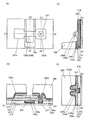
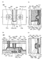
- FIGS. 4A to 4D are a top view and cross-sectional views of a semiconductor device according to one embodiment of the present invention.
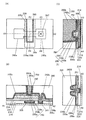
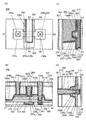
- FIGS. FIG. 6 is a cross-sectional view of a semiconductor device according to one embodiment of the present invention.
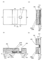
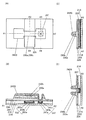
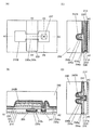
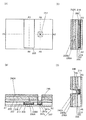
- 4A to 4D are a top view and cross-sectional views illustrating a method for manufacturing a semiconductor device according to one embodiment of the present invention.
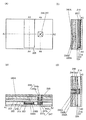
- 4A to 4D are a top view and cross-sectional views illustrating a method for manufacturing a semiconductor device according to one embodiment of the present invention.
- 4A to 4D are a top view and cross-sectional views illustrating a method for manufacturing a semiconductor device according to one embodiment of the present invention.
- 4A to 4D are a top view and cross-sectional views illustrating a method for manufacturing a semiconductor device according to one embodiment of the present invention.
- 4A to 4D are a top view and cross-sectional views illustrating a method for manufacturing a semiconductor device according to one embodiment of the present invention.
- 4A to 4D are a top view and cross-sectional views illustrating a method for manufacturing a semiconductor device according to one embodiment of the present invention.
- 4A to 4D are a top view and cross-sectional views illustrating a method for manufacturing a semiconductor device according to one embodiment of the present invention.
- 4A to 4D are a top view and cross-sectional views illustrating a method for manufacturing a semiconductor device according to one embodiment of the present invention.
- FIGS. 4A to 4D are a top view and cross-sectional views illustrating a method for manufacturing a semiconductor device according to one embodiment of the present invention.
- FIGS. 4A to 4D are a top view and cross-sectional views of a semiconductor device according to one embodiment of the present invention.
- FIGS. 4A to 4D are a top view and cross-sectional views illustrating a method for manufacturing a semiconductor device according to one embodiment of the present invention.
- 4A to 4D are a top view and cross-sectional views illustrating a method for manufacturing a semiconductor device according to one embodiment of the present invention.
- 4A to 4D are a top view and cross-sectional views illustrating a method for manufacturing a semiconductor device according to one embodiment of the present invention.
- FIGS. 4A to 4D are a top view and cross-sectional views of a semiconductor device according to one embodiment of the present invention.
- FIGS. FIGS. 4A to 4D are a top view and cross-sectional views of a semiconductor device according to one embodiment of the present invention.
- FIGS. 4A to 4D are a top view and cross-sectional views illustrating a method for manufacturing a semiconductor device according to one embodiment of the present invention.
- 4A to 4D are a top view and cross-sectional views illustrating a method for manufacturing a semiconductor device according to one embodiment of the present invention.
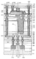
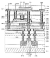
- FIG. 10 is a cross-sectional view illustrating a structure of a memory device according to one embodiment of the present invention.
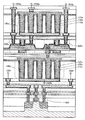
- FIG. 10 is a cross-sectional view illustrating a structure of a memory device according to one embodiment of the present invention.
- FIG. 10 is a cross-sectional view illustrating a structure of a memory device according to one embodiment of the present invention.
- FIG. 10 is a cross-sectional view illustrating a structure of a memory device according to one embodiment of the present invention.
- FIG. 10 is a cross-sectional view illustrating a structure of a memory device according to one embodiment of the present invention.
- FIG. 10 is a cross-sectional view illustrating a structure of a memory device according to one embodiment of the present invention.
- FIG. 10 is a cross-sectional view illustrating a structure of a memory device according to one embodiment of the present invention.
- FIG. 10 is a cross-sectional view illustrating a structure of a memory device according to one embodiment of the present invention.
- FIG. 10 is a cross-sectional view illustrating a structure of a memory device according to one embodiment of the present invention.
- FIG. 10 is a cross-sectional view illustrating a structure of a memory device according to one embodiment of the present invention.
- FIG. 10 is a cross-sectional view illustrating a structure of a memory device according to one embodiment of the present invention.
- FIG. 10 is a cross-sectional view illustrating a structure of a memory device according to one embodiment of the present invention.
- FIG. 10 is a cross-sectional view illustrating a structure of a memory device according to one embodiment of the present invention.
- 4A and 4B are a block diagram and a schematic diagram illustrating a structure example of a memory device according to one embodiment of the present invention.
- FIGS. 4A to 4H are circuit diagrams illustrating structural examples of a memory device according to one embodiment of the present invention.
- FIGS. 4A and 4B are a schematic diagram and a block diagram of a semiconductor device according to one embodiment of the present invention.
- FIGS. FIGS. 4A to 4E are schematic views of a memory device according to one embodiment of the present invention.
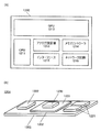
- FIGS. 4A and 4B each illustrate a product image that can be used for a semiconductor device of one embodiment of the present invention.
- FIGS. 5A to 5H each illustrate an electronic device according to one embodiment of the present invention.
- a top view also referred to as a “plan view”
- a perspective view a perspective view, and the like
- some components may be omitted in order to facilitate understanding of the invention.
- description of some hidden lines may be omitted.
- the ordinal numbers attached as the first and second are used for convenience and do not indicate the order of steps or the order of lamination. Therefore, for example, the description can be made by appropriately replacing “first” with “second” or “third”.
- the ordinal numbers described in this specification and the like may not match the ordinal numbers used to specify one embodiment of the present invention.
- X and Y are assumed to be objects (for example, devices, elements, circuits, wirings, electrodes, terminals, conductive films, layers, etc.).
- the functions of the source and drain may be switched when transistors with different polarities are used or when the direction of current changes during circuit operation. Therefore, in this specification and the like, the terms “source” and “drain” may be used interchangeably.
- the channel width in a region where a channel is actually formed (hereinafter also referred to as an “effective channel width”) and the channel width shown in the top view of the transistor (Hereinafter also referred to as “apparent channel width”) may be different.
- the effective channel width when the gate electrode covers the side surface of the semiconductor, the effective channel width may be larger than the apparent channel width, and the influence may not be negligible.
- the ratio of a channel formation region formed on the side surface of the semiconductor may increase. In that case, the effective channel width is larger than the apparent channel width.
- channel width when it is simply described as a channel width, it may indicate an apparent channel width.
- channel width in the case where the term “channel width” is simply used, it may denote an effective channel width. Note that the channel length, channel width, effective channel width, apparent channel width, and the like can be determined by analyzing a cross-sectional TEM image or the like.
- the impurity of the semiconductor means, for example, a component other than the main component constituting the semiconductor.
- an element having a concentration of less than 0.1 atomic% can be said to be an impurity.
- impurities for example, DOS (Density of States) of a semiconductor may increase or crystallinity may decrease.
- examples of the impurity that changes the characteristics of the semiconductor include a Group 1 element, a Group 2 element, a Group 13 element, a Group 14 element, a Group 15 element, and an oxide semiconductor.
- water may also function as an impurity.
- oxygen vacancies also referred to as V O : oxygen vacancy
- examples of impurities that change the characteristics of the semiconductor include group 1 elements, group 2 elements, group 13 elements, and group 15 elements excluding oxygen and hydrogen.
- silicon oxynitride has a higher oxygen content than nitrogen.
- silicon nitride oxide has a composition containing more nitrogen than oxygen.
- the term “insulator” can be referred to as an insulating film or an insulating layer.
- the term “conductor” can be restated as a conductive film or a conductive layer.
- the term “semiconductor” can be restated as a semiconductor film or a semiconductor layer.
- parallel means a state in which two straight lines are arranged at an angle of ⁇ 10 degrees to 10 degrees. Therefore, the case of -5 degrees or more and 5 degrees or less is also included.
- substantially parallel means a state in which two straight lines are arranged at an angle of ⁇ 30 degrees to 30 degrees.
- Vertical means a state in which two straight lines are arranged at an angle of 80 degrees to 100 degrees. Therefore, the case of 85 degrees or more and 95 degrees or less is also included.
- substantially vertical means a state in which two straight lines are arranged at an angle of 60 degrees to 120 degrees.
- the barrier film refers to a film having a function of suppressing permeation of impurities such as water and hydrogen and oxygen.
- the barrier film When the barrier film has conductivity, the barrier film Sometimes called.
- a metal oxide is a metal oxide in a broad sense.
- Metal oxides are classified into oxide insulators, oxide conductors (including transparent oxide conductors), and oxide semiconductors (also referred to as oxide semiconductors or simply OS).
- oxide semiconductors also referred to as oxide semiconductors or simply OS.
- the metal oxide may be referred to as an oxide semiconductor. That is, in the case of describing an OS FET or an OS transistor, it can be said to be a transistor including an oxide or an oxide semiconductor.
- normally-off means that when a potential is not applied to the gate or a ground potential is applied to the gate, a current per channel width of 1 ⁇ m flowing through the transistor is 1 ⁇ 10 ⁇ 20 at room temperature. A or lower, 1 ⁇ 10 ⁇ 18 A or lower at 85 ° C., or 1 ⁇ 10 ⁇ 16 A or lower at 125 ° C.
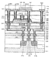
- ⁇ Configuration example of semiconductor device> 1A, 1B, 1C, and 1D are a top view and a cross-sectional view of the transistor 200 and the periphery of the transistor 200 according to one embodiment of the present invention.
- FIG. 1A is a top view of a semiconductor device having a transistor 200.
- FIG. 1B, 1C, and 1D are cross-sectional views of the semiconductor device.
- FIG. 1B is a cross-sectional view taken along dashed-dotted line A1-A2 in FIG. 1A and also a cross-sectional view in the channel length direction of the transistor 200.
- FIG. 1C is a cross-sectional view taken along the dashed-dotted line A3-A4 in FIG. 1A and is a cross-sectional view in the channel width direction of the transistor 200.
- 1D is a cross-sectional view taken along dashed-dotted line A5-A6 in FIG. 1A and is a cross-sectional view in the channel width direction of the source region or the drain region of the transistor 200.
- the semiconductor device of one embodiment of the present invention includes an insulator 214 over a substrate (not shown), the transistor 200 over the insulator 214, the insulator 280 over the transistor 200, and the insulator 282 over the insulator 280. And an insulator 274 over the insulator 282 and an insulator 281 over the insulator 274.
- the insulator 214, the insulator 280, the insulator 282, the insulator 274, and the insulator 281 function as an interlayer film.
- a conductor 247 is provided so as to be embedded in the insulator 216 provided over the insulator 214.
- the conductor 247 is electrically connected to the transistor 200 and functions as a plug.
- a conductor 240 that is electrically connected to the transistor 200 and functions as a plug is provided. Note that an insulator 241 is provided in contact with a side surface of the conductor 240 functioning as a plug.
- An insulator 241 is provided in contact with an inner wall of the opening of the insulator 256 (the insulator 256a and the insulator 256b), the insulator 280, the insulator 282, the insulator 274, and the insulator 281.
- a first conductor of the conductor 240 is provided in contact with the side surface, and a second conductor of the conductor 240 is provided further inside.
- the height of the upper surface of the conductor 240 and the height of the upper surface of the insulator 281 can be approximately the same.
- the conductor 240 may be provided as a single layer or a stacked structure of three or more layers. When a structure has a laminated structure, an ordinal number may be given in the order of formation to be distinguished.
- the transistor 200 includes an insulator 216 over an insulator 214, a conductor 205 (a conductor 205 a and a conductor 205 b) arranged to be embedded in the insulator 216, and an insulator 216. And the insulator 222 on the conductor 205, the insulator 224 on the insulator 222, the oxide 230a on the insulator 224, the oxide 230b on the oxide 230a, and the conductor on the oxide 230b.
- the oxide 230c is in contact with the side surface of the conductor 242a and the side surface of the conductor 242b.
- the conductor 260 has the conductor 260a and the conductor 260b, and the conductor 260a is arrange
- the height of the upper surface of the conductor 260 is substantially coincident with the height of the upper surface of the insulator 250 and the upper surface of the oxide 230c.
- the insulator 282 is in contact with the upper surfaces of the conductor 260, the oxide 230c, the insulator 250, and the insulator 280.
- an opening is formed in the insulator 216, and the above-described conductor 247 is disposed in the opening. At least a part of the upper surface of the conductor 247 is exposed from the insulator 216, and the height of the upper surface of the conductor 247 and the height of the upper surface of the insulator 216 are preferably substantially the same.
- the conductor 247 electrically connects a circuit element such as a switch, a transistor, a capacitor, an inductor, a resistor, and a diode, a wiring, an electrode, or a terminal provided below the insulator 214, and the transistor 200. Functions as a plug for connection.
- the conductor 247 may be configured to be electrically connected to one of the electrodes of the capacitor provided below the insulator 214.
- the conductor 247 may be electrically connected to the gate of a transistor provided below the insulator 214.
- an opening 248 that exposes at least part of the conductor 247 is formed in the insulator 222, the insulator 224, the oxide 230a, and the oxide 230b.
- the conductor 242b is disposed on the oxide 230b and is in contact with at least part of the upper surface of the conductor 247 through the opening 248. In this manner, the electrical resistance between the source or drain of the transistor 200 and the conductor 247 can be reduced by connecting the conductor 242b and the conductor 247.
- the frequency characteristics of the semiconductor device including the transistor 200 can be improved and the electrical characteristics can be improved.
- At least part of a circuit element such as a switch, a transistor, a capacitor, an inductor, a resistor, or a diode, a wiring, an electrode, or a terminal that is electrically connected to the conductor 247 overlaps with the oxide 230. It is preferable to do. Thus, the area occupied by the transistor 200, the circuit element, the wiring, the electrode, or the terminal in a top view can be reduced, so that the semiconductor device according to this embodiment can be miniaturized or highly integrated. .
- the conductor 242b is preferably provided inside the opening 248 so as to be in contact with the side surface of the oxide 230a and the side surface of the oxide 230b.
- the conductor 247 is provided below the conductor 242b; however, the semiconductor device described in this embodiment is not limited thereto.
- the conductor 247 may be provided below the conductor 242a, or the conductor 247 may be provided below both the conductor 242a and the conductor 242b.
- the insulator 222, the insulator 256 (the insulator 256a and the insulator 256b), and the insulator 282 have a function of suppressing diffusion of hydrogen (for example, at least one of a hydrogen atom and a hydrogen molecule). preferable.
- the insulator 222, the insulator 256, and the insulator 282 preferably have a function of suppressing diffusion of oxygen (for example, at least one of oxygen atoms and oxygen molecules).
- the insulator 222, the insulator 256, and the insulator 282 each preferably have lower permeability to one or both of oxygen and hydrogen than the insulator 224.
- the insulator 222, the insulator 256, and the insulator 282 preferably each have lower permeability to one or both of oxygen and hydrogen than the insulator 250.
- the insulator 222, the insulator 256, and the insulator 282 preferably have lower permeability of one or both of oxygen and hydrogen than the insulator 280, respectively.
- the conductor 242a and the conductor 242b are provided over the oxide 230b
- the insulator 256 includes an upper surface and a side surface of the conductor 242a, an upper surface and a side surface of the conductor 242b,
- the side surface of the object 230b, the side surface of the oxide 230a, and the top surface of the insulator 224 are preferably in contact with each other.
- the insulator 256 preferably has a stacked structure including the insulator 256a and the insulator 256b.
- the side surfaces of the oxide 230a and the oxide 230b are not in contact with the conductor 242a and the conductor 242b on the outer side surface other than the opening 248, and the insulator 280 is not in contact with the insulator 256 (insulator 256a, And the insulator 256b) are separated from the insulator 224, the oxide 230a, and the oxide 230b.
- the oxide 230 includes the oxide 230a over the insulator 224, the oxide 230b over the oxide 230a, and the oxide 230c disposed over the oxide 230b and in contact with at least part of the top surface of the oxide 230b. It is preferable to have.
- the oxide 230 has a structure in which a single layer of the oxide 230b, a two-layer structure of the oxide 230b and the oxide 230a, a two-layer structure of the oxide 230b and the oxide 230c, or a stacked structure of four or more layers is provided. Also good.
- each of the oxide 230a, the oxide 230b, and the oxide 230c may have a stacked structure of two or more layers.
- the conductor 260 is illustrated as a two-layer structure, but the present invention is not limited to this.
- the conductor 260 may have a single layer structure or a stacked structure of three or more layers.
- the conductor 260 functions as a gate electrode of the transistor, and the conductor 242a and the conductor 242b function as a source electrode or a drain electrode, respectively.
- the transistor 200 is formed in a self-aligning manner so that a conductor 260 functioning as a gate electrode fills an opening formed by the insulator 280 and the like. By forming the conductor 260 in this manner, the conductor 260 can be reliably arranged in the region between the conductors 242a and 242b without being aligned.
- a metal oxide functioning as an oxide semiconductor (hereinafter also referred to as an oxide semiconductor) is used for the oxide 230 (the oxide 230a, the oxide 230b, and the oxide 230c) including a channel formation region. It is preferable to use it.
- An oxide semiconductor can be formed by a sputtering method or the like, and thus can be used for the transistor 200 included in a highly integrated semiconductor device.
- the oxide 230 includes an In-M-Zn oxide (the element M is aluminum, gallium, yttrium, tin, copper, vanadium, beryllium, boron, titanium, iron, nickel, germanium, zirconium, molybdenum, lanthanum, cerium) It is preferable to use a metal oxide such as neodymium, hafnium, tantalum, tungsten, or magnesium.
- the element M may be aluminum, gallium, yttrium, or tin.
- an In—Ga oxide or an In—Zn oxide may be used as the oxide 230.
- the carrier density when an impurity such as hydrogen, nitrogen, or a metal element is present, the carrier density may increase and the resistance may be lowered. Further, when the concentration of oxygen contained in the oxide 230 is decreased, the carrier density may be increased and the resistance may be decreased.
- the conductor 242 (the conductor 242a and the conductor 242b) that is provided in contact with the oxide 230b and functions as a source electrode or a drain electrode has a function of absorbing oxygen of the oxide 230, or the oxide
- the oxide 230 has a function of supplying impurities such as hydrogen, nitrogen, or a metal element
- a low-resistance region may be partially formed in the oxide 230.
- the conductor 242 is formed over the oxide 230b and does not contact the side surfaces of the oxide 230a and the oxide 230b or the insulator 224 except for the opening 248, that is, on the outer peripheral side surface.
- the oxide 230a and the oxide 230b particularly oxygen contained in the channel formation region and the vicinity thereof, can be prevented from being absorbed by the conductor 242 from the side surfaces of the oxide 230a and the oxide 230b. .
- the insulator 256 is provided so that the side surfaces of the oxide 230a and the oxide 230b do not directly touch the insulator 280. Further, it is provided to suppress oxidation of the conductor 242. Note that the insulator 256 does not need to have an effect of suppressing the oxidation of the conductor 242 in the case where the conductivity does not decrease significantly even when the conductor 242 absorbs the oxidation-resistant material or oxygen.
- oxygen which the insulator 280 has can be suppressed from being injected from the side surfaces of the oxide 230a and the oxide 230b.
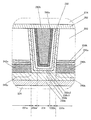
- FIG. 1B An enlarged view of the vicinity of the channel formation region in FIG. 1B is shown in FIG.
- a conductor 242 is provided so as to be in contact with the oxide 230b, and a region 249 (region 249a, region 249) is formed as a low resistance region at and near the interface of the oxide 230 with the conductor 242. And regions 249b) are formed.
- the oxide 230 includes a region 234 functioning as a channel formation region of the transistor 200, a region 231 (region 231a and region 231b) functioning as a source region or a drain region, and a region 232 (region) between the region 234 and the region 231. 232a and region 232b).
- the region 231 includes a region 249.
- the oxide 230c has a stacked structure including the oxide 230c1 and the oxide 230c2, but this embodiment is not limited thereto.
- the oxide 230c may have a single-layer structure or a stacked structure including three or more layers.
- the region 249 in particular has a low oxygen concentration or a region in which a carrier concentration is increased due to containing an impurity such as hydrogen, nitrogen, or a metal element, thereby reducing resistance. It is. That is, the region 231 has a higher carrier density and lower resistance than the region 234.
- the region 234 functioning as a channel formation region is a high-resistance region with a low carrier density because the oxygen concentration is higher or the impurity concentration is lower than the region 249 in the region 231.
- the oxygen concentration in the region 232 is preferably equal to or higher than the oxygen concentration in the region 231 and is preferably equal to or lower than the oxygen concentration in the region 234.
- the impurity concentration of the region 232 is preferably equal to or lower than the impurity concentration of the region 231 and is preferably equal to or higher than the impurity concentration of the region 234.
- the region 232 has a resistance value similar to that of the region 234 depending on the concentration of oxygen contained in the region and the concentration of impurities, and thus functions as a channel formation region like the region 234.
- the low resistance region having the same resistance value or a low resistance region having higher resistance than the region 231 and lower resistance than the region 234 may function.
- the impurity contained in the region 231 is likely to diffuse in the ab plane direction, and the region 232 may have low resistance.
- the region 249 which is a low-resistance region includes a metal element
- the region 249 includes, in addition to the metal element included in the oxide 230, aluminum, chromium, copper, silver, gold, platinum, tantalum, nickel, titanium, It is preferable to have one or more metal elements selected from metal elements such as molybdenum, tungsten, hafnium, vanadium, niobium, manganese, magnesium, zirconium, beryllium, indium, ruthenium, iridium, strontium, and lanthanum. .
- the region 249 is formed in the vicinity of the interface between the oxide 230b and the conductor 242 in the film thickness direction of the oxide 230b.
- the present invention is not limited to this.
- the region 249 may have substantially the same thickness as the oxide 230b or may be formed in the oxide 230a.
- the region 249 is formed only in the region 231; however, the present embodiment is not limited to this.
- the region 249 may be formed in the region 231 and the region 232, or a part of the region 231 and a part of the region 232. It may be formed, or may be formed in part of the region 231, part of the region 232, and part of the region 234.
- concentrations of metal elements detected in each region and impurity elements such as hydrogen and nitrogen are not limited to stepwise changes in each region, but also continuously change in each region (also referred to as gradation). May be. That is, the closer to the channel formation region, the lower the concentration of the metal element and impurity elements such as hydrogen and nitrogen.
- the conductor 242 may be aluminum, chromium, copper, silver, gold, platinum, tantalum, nickel, titanium, molybdenum, tungsten, hafnium, vanadium, niobium, It is preferable to use a material containing at least one of a metal element that enhances conductivity, such as manganese, magnesium, zirconium, beryllium, indium, ruthenium, iridium, strontium, and lanthanum, and an impurity.
- a metal element that enhances conductivity such as manganese, magnesium, zirconium, beryllium, indium, ruthenium, iridium, strontium, and lanthanum, and an impurity.
- a material, a deposition method, or the like in which an impurity such as an element that forms oxygen vacancies or an element that is trapped by oxygen vacancies is injected into the oxide 230 can be used.
- the element include hydrogen, boron, carbon, nitrogen, fluorine, phosphorus, sulfur, chlorine, and a rare gas element.
- rare gas elements include helium, neon, argon, krypton, and xenon.
- a transistor including an oxide semiconductor if impurities and oxygen vacancies exist in a region where a channel is formed in the oxide semiconductor, electric characteristics are likely to fluctuate and reliability may be deteriorated.
- an oxygen vacancy is included in a region where a channel is formed in an oxide semiconductor, the transistor is likely to be normally on. Therefore, oxygen vacancies in the region 234 where a channel is formed are preferably reduced as much as possible.
- the insulator 250 adjacent to the oxide 230 preferably contains more oxygen (also referred to as excess oxygen) than oxygen that satisfies the stoichiometric composition. Oxygen included in the insulator 250 can diffuse into the oxide 230, reduce oxygen vacancies in the oxide 230, and suppress normally-on of the transistor.
- oxygen vacancies in the region 234 of the oxide 230 can be reduced by diffusion of oxygen included in the insulator 250 into the region 234 of the oxide 230. Further, oxygen vacancies in the region 234 of the oxide 230 can be reduced by diffusion of oxygen contained in the insulator 280 into the region 234 of the oxide 230 through the oxide 230c.
- the oxide 230 c has a stacked structure including the oxide 230 c 1 and the oxide 230 c 2, and oxygen contained in the insulator 280 is supplied to the region 234 of the oxide 230 through the oxide 230 c 1. It may be configured to diffuse.
- oxide 230c2 By using a material that does not easily transmit oxygen as the oxide 230c2, diffusion of oxygen in the insulator 280 to the insulator 250 or the conductor 260 can be suppressed, and the oxygen in the insulator 280 can be reduced to oxide. 230 can be efficiently supplied to the region 234.
- the transistor 200 which is one embodiment of the present invention has a structure in which the insulator 282 and the insulator 250 are in direct contact with each other as illustrated in FIGS.
- oxygen contained in the insulator 280 is hardly absorbed by the conductor 260. Therefore, oxygen contained in the insulator 280 can be efficiently injected into the oxide 230a and the oxide 230b through the oxide 230c, so that oxygen vacancies in the oxide 230a and the oxide 230b are reduced.
- electrical characteristics and reliability of the transistor 200 can be improved. Further, since impurities such as hydrogen contained in the insulator 280 can be prevented from entering the insulator 250, adverse effects on the electrical characteristics and reliability of the transistor 200 can be suppressed.
- silicon nitride, silicon nitride oxide, aluminum oxide, or hafnium oxide can be used.
- silicon nitride is particularly preferable.
- the silicon nitride can suitably block impurities (for example, hydrogen, water, etc.) that can enter from the outside.
- the insulator 256 has a function of suppressing permeation of impurities such as hydrogen and water and oxygen.
- the insulator 256 may be a single layer or a stacked structure including two or more layers including the insulator 256a and the insulator 256b.
- As the insulator 256a or the insulator 256b for example, aluminum oxide, hafnium oxide, a silicon oxide film, a silicon nitride film, or a silicon nitride oxide film can be used. Further, the same material may be used as the insulator 256a and the insulator 256b, or different materials may be used.
- the insulator 256a and the insulator 256b may be formed using different film formation methods.
- the insulator 256a may be formed using a sputtering method, and the insulator 256b may be formed using an ALD method.
- the insulator 256a may be formed using an ALD method, and the insulator 256b may be formed using a sputtering method.
- a material that can be used for the oxide 230 may be used for the insulator 256.
- FIG. 1D is a cross-sectional view taken along the dashed-dotted line A5-A6 in FIG. 1A, and is also a cross-sectional view in the channel width direction of the source region or the drain region of the transistor 200.
- the top surface of the conductor 242b and the side surface of the conductor 242b are covered with the insulator 256, the side surface of the conductor 242b and the top surface direction of the conductor 242b are viewed. Diffusion of impurities such as hydrogen and water and oxygen into the conductor 242b can be suppressed.
- the conductor 242a has the same effect.
- diffusion of impurities such as hydrogen and water into the oxide 230a and the oxide 230b from the side surface of the oxide 230a and the side surface direction of the oxide 230b can be suppressed.
- the height of the bottom surface of the conductor 260 in a region where the oxide 230a and the oxide 230b and the conductor 260 do not overlap with respect to the bottom surface of the insulator 224 is The height is preferably lower than the height of the bottom surface of the oxide 230b.
- the difference between the height of the bottom surface of the conductor 260 and the height of the bottom surface of the oxide 230b in a region where the oxide 230b and the conductor 260 do not overlap with each other is 0 nm to 100 nm, preferably 3 nm to 50 nm. Hereinafter, it is more preferably 5 nm or more and 20 nm or less.
- the conductor 260 functioning as a gate electrode has a structure in which the side surface and the upper surface of the oxide 230b in the channel formation region are covered with the oxide 230c and the insulator 250, and the electric field of the conductor 260 is channeled. This easily acts on the entire oxide 230b in the formation region. Thus, the on-state current of the transistor 200 can be increased and the frequency characteristics can be improved.
- a miniaturized or highly integrated semiconductor device can be provided.
- a semiconductor device including a transistor with high on-state current can be provided.
- a semiconductor device including a transistor having high frequency characteristics can be provided.
- a semiconductor device including a transistor with low off-state current can be provided.
- the conductor 205 is disposed so as to overlap with the oxide 230 and the conductor 260.
- the conductor 205 is preferably provided so as to be embedded in the insulator 214 and the insulator 216.
- the conductor 260 may function as a first gate (also referred to as a top gate) electrode.
- the conductor 205 may function as a second gate (also referred to as a bottom gate) electrode.
- Vth of the transistor 200 can be controlled by changing the potential applied to the conductor 205 independently of the potential applied to the conductor 260 without being interlocked.
- Vth of the transistor 200 can be made higher than 0 V and off-state current can be reduced. Therefore, when a negative potential is applied to the conductor 205, the drain current when the potential applied to the conductor 260 is 0 V can be made smaller than when a negative potential is not applied.
- the conductor 205 is preferably provided larger than the size of a region of the oxide 230 that does not overlap with the conductors 242a and 242b.
- the conductor 205 is preferably extended also in a region outside the end portion intersecting with the channel width direction of the oxide 230. That is, it is preferable that the conductor 205 and the conductor 260 overlap with each other with an insulator outside the side surface in the channel width direction of the oxide 230.
- charge-up local charging may be reduced in the treatment using plasma in the manufacturing process after the conductor 205 is formed. Note that one embodiment of the present invention is not limited to this.
- the conductor 205 may overlap with at least the oxide 230 located between the conductor 242a and the conductor 242b.
- the channel formation region is electrically surrounded by the electric field of the conductor 260 functioning as the first gate electrode and the electric field of the conductor 205 functioning as the second gate electrode.
- a transistor structure that electrically surrounds a channel formation region by an electric field of the first gate electrode and the second gate electrode is referred to as a surrounded channel (S-channel) structure.
- the conductor 205a is preferably a conductor that suppresses permeation of impurities such as water or hydrogen and oxygen.
- impurities such as water or hydrogen and oxygen.
- titanium, titanium nitride, tantalum, or tantalum nitride can be used.
- the conductor 205b is preferably formed using a conductive material containing tungsten, copper, or aluminum as a main component. Note that although the conductor 205 is illustrated as having two layers, it may have a multilayer structure of three or more layers.
- the insulator 214, the insulator 256, the insulator 282, and the insulator 281 function as barrier insulating films that prevent impurities such as water or hydrogen from entering the transistor 200 from the substrate side or from above.
- the insulator 214, the insulator 256, the insulator 282, and the insulator 281 include a hydrogen atom, a hydrogen molecule, a water molecule, a nitrogen atom, a nitrogen molecule, a nitrogen oxide molecule (N 2 O, NO, NO 2, and the like), It is preferable to use an insulating material having a function of suppressing diffusion of impurities such as copper atoms (the impurities are difficult to permeate). Alternatively, it is preferable to use an insulating material having a function of suppressing diffusion of oxygen (for example, at least one of an oxygen atom and an oxygen molecule) (the oxygen hardly transmits).
- silicon nitride or the like is preferably used for the insulator 214, the insulator 256, the insulator 282, and the insulator 281.
- diffusion of impurities such as water or hydrogen from the substrate side to the transistor 200 side with respect to the insulator 214 can be suppressed.
- diffusion of oxygen contained in the insulator 224 and the like to the substrate side with respect to the insulator 214 can be suppressed.
- diffusion of impurities such as water or hydrogen from the insulator 280 or the like disposed above the insulator 256 to the transistor 200 side can be suppressed.
- the resistivity of the insulator 214, the insulator 256, the insulator 282, and the insulator 281 is preferably 1 ⁇ 10 10 ⁇ cm to 1 ⁇ 10 15 ⁇ cm.
- the insulator 214 may have a laminated structure.
- a stacked structure of an aluminum oxide film and a silicon nitride film is preferably used for the insulator 214.
- Oxygen can be supplied below the insulator 214 by the aluminum oxide film.
- diffusion of impurities such as hydrogen and water which are diffused from the substrate side to the transistor 200 side can be suppressed by the silicon nitride film.
- the insulator 216, the insulator 280, and the insulator 274 preferably have a lower dielectric constant than the insulator 214.
- a material having a low dielectric constant as the interlayer film, parasitic capacitance generated between the wirings can be reduced.
- silicon oxide, silicon oxynitride, silicon nitride oxide, silicon nitride, silicon oxide added with fluorine, silicon oxide added with carbon, carbon, and nitrogen were added. Silicon oxide, silicon oxide having holes, or the like may be used as appropriate.
- the insulator 222 and the insulator 224 have a function as a gate insulator.
- the insulator 224 in contact with the oxide 230 desorbs oxygen by heating.
- oxygen released by heating may be referred to as excess oxygen.
- the insulator 224 may be formed using silicon oxide, silicon oxynitride, or the like as appropriate.
- an oxide material from which part of oxygen is released by heating is preferably used as the insulator 224.
- the oxide that desorbs oxygen by heating means that the amount of desorbed oxygen in terms of oxygen molecules is 1.0 ⁇ 10 18 molecules / cm 3 or more, preferably 1 in TDS (Thermal Desorption Spectroscopy) analysis.
- the oxide film has a thickness of 0.0 ⁇ 10 19 molecules / cm 3 or more, more preferably 2.0 ⁇ 10 19 molecules / cm 3 or more, or 3.0 ⁇ 10 20 molecules / cm 3 or more.
- the surface temperature of the film at the time of the TDS analysis is preferably in the range of 100 ° C. to 700 ° C., or 100 ° C. to 400 ° C.
- the insulator 222 preferably functions as a barrier insulating film that suppresses impurities such as water or hydrogen from entering the transistor 200 from the substrate side.
- the insulator 222 preferably has lower hydrogen permeability than the insulator 224.
- the insulator 222 preferably has a function of suppressing the diffusion of oxygen (for example, at least one of oxygen atoms, oxygen molecules, and the like) (the oxygen is difficult to permeate).
- the insulator 222 preferably has lower oxygen permeability than the insulator 224.
- the insulator 222 has a function of suppressing diffusion of oxygen and impurities, which is preferable because oxygen included in the oxide 230 can be reduced from diffusing below the insulator 222.
- the conductor 205 can be prevented from reacting with the oxygen included in the insulator 224 and the oxide 230.
- an insulator containing one or both oxides of aluminum and hafnium which are insulating materials may be used.
- the insulator containing one or both of aluminum and hafnium aluminum oxide, hafnium oxide, an oxide containing aluminum and hafnium (hafnium aluminate), or the like is preferably used.
- the insulator 222 suppresses release of oxygen from the oxide 230 and entry of impurities such as hydrogen from the peripheral portion of the transistor 200 into the oxide 230. Acts as a layer.
- aluminum oxide, bismuth oxide, germanium oxide, niobium oxide, silicon oxide, titanium oxide, tungsten oxide, yttrium oxide, or zirconium oxide may be added to these insulators.
- these insulators may be nitrided. Silicon insulator, silicon oxynitride, or silicon nitride may be stacked over the above insulator.
- the insulator 222 is made of, for example, aluminum oxide, hafnium oxide, tantalum oxide, zirconium oxide, lead zirconate titanate (PZT), strontium titanate (SrTiO 3 ), or (Ba, Sr) TiO 3 (BST).
- An insulator including a so-called high-k material may be used as a single layer or a stacked layer. As transistor miniaturization and higher integration progress, problems such as leakage current may occur due to thinning of the gate insulator. By using a high-k material for the insulator functioning as a gate insulator, the gate potential during transistor operation can be reduced while maintaining the physical film thickness.
- the insulator 222 and the insulator 224 may have a stacked structure of two or more layers. In that case, it is not limited to the laminated structure which consists of the same material, The laminated structure which consists of a different material may be sufficient.
- the conductor 247 may include a first conductive layer and a second conductive layer disposed inside the first conductive layer.
- the first conductive layer of the conductor 247 is preferably a conductor that suppresses permeation of impurities such as water or hydrogen and oxygen.
- impurities such as water or hydrogen and oxygen.
- titanium, titanium nitride, tantalum, or tantalum nitride can be used.
- the second conductive layer of the conductor 247 is preferably formed using a conductive material containing tungsten, copper, or aluminum as a main component. Note that although the conductor 247 is illustrated with two layers, a multilayer structure including three or more layers may be used.
- an insulator that suppresses diffusion of impurities such as hydrogen and water and oxygen may be provided on the side surface of the conductor 247.
- the oxide 230 includes an oxide 230a, an oxide 230b on the oxide 230a, and an oxide 230c on the oxide 230b.
- the oxide 230c is arranged so that at least a part thereof overlaps with a region between the conductors 242a and 242b.
- the oxide 230 preferably has a stacked structure of oxides having different atomic ratios of metal atoms. Specifically, in the metal oxide used for the oxide 230a, the atomic ratio of the element M in the constituent element is larger than the atomic ratio of the element M in the constituent element in the metal oxide used for the oxide 230b. It is preferable. In the metal oxide used for the oxide 230a, the atomic ratio of the element M to In is preferably larger than the atomic ratio of the element M to In in the metal oxide used for the oxide 230b. In the metal oxide used for the oxide 230b, the atomic ratio of In to the element M is preferably larger than the atomic ratio of In to the element M in the metal oxide used for the oxide 230a. As the oxide 230c, a metal oxide that can be used for the oxide 230a or the oxide 230b can be used.
- the oxide 230b preferably has crystallinity.
- a CAAC-OS c-axis aligned crystalline semiconductor
- An oxide having crystallinity such as a CAAC-OS has a dense structure with few impurities and defects (such as oxygen vacancies) and high crystallinity. Accordingly, extraction of oxygen from the oxide 230b due to the source electrode or the drain electrode can be suppressed. Accordingly, even when heat treatment is performed, extraction of oxygen from the oxide 230b can be reduced, so that the transistor 200 is stable with respect to a high temperature (so-called thermal budget) in the manufacturing process.
- the energy at the lower end of the conduction band of the oxide 230a and the oxide 230c is higher than the energy at the lower end of the conduction band of the oxide 230b.
- the electron affinity of the oxide 230a and the oxide 230c is preferably smaller than the electron affinity of the oxide 230b.
- the energy level at the lower end of the conduction band changes gently.
- the energy level at the lower end of the conduction band at the junction of the oxide 230a, the oxide 230b, and the oxide 230c is continuously changed or continuously joined.
- the defect state density of the mixed layer formed at the interface between the oxide 230a and the oxide 230b and the interface between the oxide 230b and the oxide 230c is preferably low.
- the oxide 230c has a stacked structure
- In: Ga: Zn 4: 2: 3 [atomic ratio] as the oxide 230c1
- In: Ga: Zn 1 as the oxide 230c2.
- a stack structure of Ga: Zn 2: 5 [atomic ratio] as the oxide 230c2.
- the main path of the carrier is the oxide 230b.
- the oxide 230a and the oxide 230c have the above structure, the density of defect states at the interface between the oxide 230a and the oxide 230b and the interface between the oxide 230b and the oxide 230c can be reduced. Therefore, the influence on carrier conduction due to interface scattering is reduced, and the transistor 200 can obtain a high on-state current and a high frequency characteristic. Note that in the case where the oxide 230c has a stacked structure, in addition to the effect of reducing the defect state density at the interface between the oxide 230b and the oxide 230c, the constituent element of the oxide 230c is It is expected to suppress diffusion to the surface.
- the oxide 230c has a stacked structure, and an oxide that does not contain In or has a reduced In concentration is positioned above the stacked structure, so that In that can be diffused to the insulator 250 side is suppressed. can do. Since the insulator 250 functions as a gate insulator, when In is diffused, transistor characteristics are deteriorated. Therefore, with the stacked structure of the oxide 230c, a highly reliable semiconductor device can be provided.
- the main path of carriers may be the interface between the oxide 230b and the oxide 230c1 and the vicinity thereof.
- oxygen contained in the insulator 280 can be supplied to the channel formation region of the transistor 200 through the oxide 230c1.
- oxygen contained in the insulator 280 can be prevented from being transmitted through the oxide 230c2 and absorbed by the insulator 250 or the conductor 260, so that oxygen can be efficiently contained in the channel formation region. Can be supplied.
- the oxide 230 has a region 231 and a region 234. Note that at least part of the region 231 includes a region in contact with the conductor 242.
- one of the region 231a and the region 231b functions as a source region and the other functions as a drain region.
- at least part of the region 234 functions as a region where a channel is formed.
- a metal oxide that functions as an oxide semiconductor is preferably used.
- a material having an energy gap of 2 eV or more, preferably 2.5 eV or more is preferable to use. In this manner, off-state current of a transistor can be reduced by using a metal oxide having a large energy gap. By using such a transistor, a semiconductor device with low power consumption can be provided.
- the electron affinity or the energy level Ec at the lower end of the conduction band can be obtained from the ionization potential Ip, which is the difference between the vacuum level and the energy Ev at the upper end of the valence band, and the energy gap Eg.
- the ionization potential Ip can be measured using, for example, an ultraviolet photoelectron spectroscopy (UPS) apparatus.
- the energy gap Eg can be measured using, for example, a spectroscopic ellipsometer.
- a conductor 242 (conductor 242a and conductor 242b) functioning as a source electrode and a drain electrode is provided over the oxide 230b.
- the thickness of the conductor 242 may be, for example, 1 nm to 50 nm, preferably 2 nm to 25 nm.
- Examples of the conductor 242 include aluminum, chromium, copper, silver, gold, platinum, tantalum, nickel, titanium, molybdenum, tungsten, hafnium, vanadium, niobium, manganese, magnesium, zirconium, beryllium, indium, ruthenium, iridium, strontium, It is preferable to use a metal element selected from lanthanum, an alloy containing the above metal element as a component, or an alloy combining the above metal elements.
- tantalum nitride, titanium nitride, tungsten, nitride containing titanium and aluminum, nitride containing tantalum and aluminum, ruthenium oxide, ruthenium nitride, oxide containing strontium and ruthenium, oxide containing lanthanum and nickel, or the like is used. It is preferable. Also, tantalum nitride, titanium nitride, nitride containing titanium and aluminum, nitride containing tantalum and aluminum, ruthenium oxide, ruthenium nitride, oxide containing strontium and ruthenium, and oxide containing lanthanum and nickel are difficult to oxidize. A conductive material or a material that maintains conductivity even when oxygen is absorbed is preferable.
- the insulator 250 functions as a gate insulator.
- the insulator 250 is preferably provided in contact with the upper surface of the oxide 230c.
- silicon oxide, silicon oxynitride, silicon nitride oxide, silicon nitride, silicon oxide to which fluorine is added, silicon oxide to which carbon is added, silicon oxide to which carbon and nitrogen are added, or silicon oxide having a hole is used. be able to.
- silicon oxide and silicon oxynitride are preferable because they are stable against heat.
- the insulator 250 is preferably formed using an insulator from which oxygen is released by heating.
- the concentration of impurities such as water or hydrogen in the insulator 250 is preferably reduced.
- the thickness of the insulator 250 is preferably greater than or equal to 1 nm and less than or equal to 20 nm.
- a metal oxide may be provided between the insulator 250 and the conductor 260.
- the metal oxide preferably suppresses oxygen diffusion from the insulator 250 to the conductor 260.
- the diffusion of oxygen from the insulator 250 to the conductor 260 is suppressed. That is, a decrease in the amount of oxygen supplied to the oxide 230 can be suppressed. Further, oxidation of the conductor 260 due to oxygen in the insulator 250 can be suppressed.
- the metal oxide may function as a part of the gate insulator. Therefore, when silicon oxide, silicon oxynitride, or the like is used for the insulator 250, the metal oxide is preferably a metal oxide that is a high-k material with a high relative dielectric constant.
- the gate insulator has a stacked structure of the insulator 250 and the metal oxide, a stacked structure having high relative dielectric constant and stability against heat can be obtained. Therefore, it is possible to reduce the gate potential applied during transistor operation while maintaining the physical film thickness of the gate insulator. In addition, it is possible to reduce the equivalent oxide thickness (EOT) of an insulator that functions as a gate insulator.
- EOT equivalent oxide thickness
- a metal oxide containing one or more selected from hafnium, aluminum, gallium, yttrium, zirconium, tungsten, titanium, tantalum, nickel, germanium, magnesium, or the like is used. it can.
- the metal oxide may function as part of the gate electrode.
- a conductive material containing oxygen is preferably provided on the channel formation region side.
- a conductive material containing oxygen and a metal element contained in a metal oxide in which a channel is formed as a conductor functioning as a gate electrode it is preferable to use a conductive material containing oxygen and a metal element contained in a metal oxide in which a channel is formed as a conductor functioning as a gate electrode.
- the above-described conductive material containing a metal element and nitrogen may be used.
- indium tin oxide, indium oxide containing tungsten oxide, indium zinc oxide containing tungsten oxide, indium oxide containing titanium oxide, indium tin oxide containing titanium oxide, indium zinc oxide, silicon were added Indium tin oxide may be used.
- indium gallium zinc oxide containing nitrogen may be used.
- the conductor 260 is shown as a two-layer structure in FIG. 1, but may have a single-layer structure or a laminated structure of three or more layers.
- the conductor 260a has a function of suppressing diffusion of impurities such as a hydrogen atom, a hydrogen molecule, a water molecule, a nitrogen atom, a nitrogen molecule, a nitrogen oxide molecule (N 2 O, NO, NO 2 ), a copper atom, and the like. It is preferable to use a material. Alternatively, it is preferable to use a conductive material having a function of suppressing diffusion of oxygen (for example, at least one of oxygen atoms and oxygen molecules).
- the conductor 260a has a function of suppressing diffusion of oxygen, it is possible to prevent the conductivity of the conductor 260b from being oxidized by the oxygen contained in the insulator 250 and the conductivity from being lowered.
- tantalum, tantalum nitride, ruthenium, or ruthenium oxide is preferably used as the conductive material having a function of suppressing oxygen diffusion.
- the conductor 260b be made of a conductive material mainly containing tungsten, copper, or aluminum.
- a conductor having high conductivity is preferably used.
- a conductive material containing tungsten, copper, or aluminum as a main component can be used.
- the conductor 260b may have a stacked structure, for example, a stacked structure of titanium, titanium nitride, and the conductive material.
- the insulator 280 is formed using, for example, silicon oxide, silicon oxynitride, silicon nitride oxide, silicon oxide to which fluorine is added, silicon oxide to which carbon is added, silicon oxide to which carbon and nitrogen are added, or silicon oxide having holes. It is preferable to have. In particular, silicon oxide and silicon oxynitride are preferable because they are thermally stable. In particular, a material such as silicon oxide, silicon oxynitride, or silicon oxide having a hole is preferable because a region containing oxygen that is released by heating can be easily formed.
- the insulator 280 In order to supply oxygen contained in the insulator 280 to the oxide 230b through the oxide 230c or the oxide 230c1, the insulator 280 preferably contains more oxygen, for example, stoichiometry. Preferably it contains more oxygen than the ratio. In order to increase the concentration of oxygen contained in the insulator 280, the deposition gas used for forming the insulator 280 preferably contains oxygen.
- the concentration of impurities such as water or hydrogen in the insulator 280 is reduced.
- a silicon oxide formed by a sputtering method using a target containing silicon or silicon oxide and a gas containing argon or oxygen is formed by a CVD method using a deposition gas containing hydrogen. Since the hydrogen concentration in the film is low as compared with silicon oxynitride, the insulator 280 is preferable.
- the insulator 280 may be formed using a CVD method in consideration of a deposition rate when forming the insulator 280 and coverage with respect to a step portion by the oxide 230a, the oxide 230b, the opening 248, and the like. Good.
- the insulator 280 may have a stacked structure of two or more layers, and silicon oxide formed by a sputtering method as a first layer is formed by a CVD method as a second layer. Silicon oxynitride may be included. Further, the upper surface of the insulator 280 may be planarized.
- the insulator 282 preferably functions as a barrier insulating film that suppresses impurities such as water or hydrogen from entering the insulator 280 from above.
- an insulator such as aluminum oxide, silicon nitride, or silicon nitride oxide may be used.
- an insulator 274 that functions as an interlayer film is preferably provided over the insulator 282.
- the insulator 274 preferably has a reduced concentration of impurities such as water or hydrogen in the insulator 274.
- the conductor 240 is preferably made of a conductive material mainly composed of tungsten, copper, or aluminum. Further, the conductor 240 may have a stacked structure.
- the conductor in contact with the insulator 281, the insulator 274, the insulator 282, the insulator 280, and the insulator 256 has a function of suppressing permeation of impurities such as water or hydrogen.
- a conductive material having For example, tantalum, tantalum nitride, titanium, titanium nitride, ruthenium, or ruthenium oxide is preferably used.
- the conductive material having a function of suppressing permeation of impurities such as water or hydrogen may be used in a single layer or a stacked layer.
- oxygen added to the insulator 280 can be prevented from being absorbed by the conductor 240.
- impurities such as water or hydrogen from an upper layer than the insulator 281 can be prevented from entering the oxide 230 through the conductor 240.
- an insulator such as aluminum oxide, silicon nitride, or silicon nitride oxide may be used. Since the insulator 241 is provided in contact with the insulator 256, impurities such as water or hydrogen from the insulator 280 and the like can be prevented from entering the oxide 230 through the conductor 240. Further, oxygen contained in the insulator 280 can be prevented from being absorbed by the conductor 240.
- a conductor functioning as a wiring may be disposed in contact with the upper surface of the conductor 240.
- a conductive material containing tungsten, copper, or aluminum as a main component is preferably used.
- the conductor may have a stacked structure, for example, a stack of titanium, titanium nitride, and the conductive material. Note that the conductor may be formed so as to be embedded in an opening provided in the insulator.
- an insulator substrate As a substrate over which the transistor 200 is formed, for example, an insulator substrate, a semiconductor substrate, or a conductor substrate may be used.
- the insulator substrate include a glass substrate, a quartz substrate, a sapphire substrate, a stabilized zirconia substrate (such as a yttria stabilized zirconia substrate), and a resin substrate.
- the semiconductor substrate include a semiconductor substrate made of silicon or germanium, or a compound semiconductor substrate made of silicon carbide, silicon germanium, gallium arsenide, indium phosphide, zinc oxide, or gallium oxide.
- a semiconductor substrate having an insulator region inside the above-described semiconductor substrate for example, an SOI (Silicon On Insulator) substrate.
- the conductor substrate include a graphite substrate, a metal substrate, an alloy substrate, and a conductive resin substrate.
- a substrate in which a conductor or a semiconductor is provided on an insulator substrate a substrate in which a conductor or an insulator is provided on a semiconductor substrate, a substrate in which a semiconductor or an insulator is provided on a conductor substrate, and the like.
- a substrate in which an element is provided may be used. Examples of the element provided on the substrate include a capacitor element, a resistor element, a switch element, a light emitting element, and a memory element.
- the insulator examples include an insulating oxide, nitride, oxynitride, nitride oxide, metal oxide, metal oxynitride, and metal nitride oxide.
- the transistor when the transistor is miniaturized and highly integrated, problems such as leakage current may occur due to thinning of the gate insulator.
- a high-k material for the insulator functioning as a gate insulator the voltage during transistor operation can be reduced while maintaining the physical film thickness.
- a parasitic capacitance generated between wirings can be reduced by using a material having a low relative dielectric constant for the insulator functioning as an interlayer film. Therefore, the material may be selected according to the function of the insulator.
- Insulators having a high relative dielectric constant include gallium oxide, hafnium oxide, zirconium oxide, oxides containing aluminum and hafnium, oxynitrides containing aluminum and hafnium, oxides containing silicon and hafnium, silicon and hafnium.
- an oxynitride having silicon, or a nitride having silicon and hafnium are examples of gallium oxide, hafnium oxide, zirconium oxide, oxides containing aluminum and hafnium, oxynitrides containing aluminum and hafnium, oxides containing silicon and hafnium, silicon and hafnium.
- Insulators having a low dielectric constant include silicon oxide, silicon oxynitride, silicon nitride oxide, silicon oxide to which fluorine is added, silicon oxide to which carbon is added, silicon oxide to which carbon and nitrogen are added, and voids There is silicon oxide or resin.
- a transistor including an oxide semiconductor can be stabilized in electrical characteristics of the transistor by being surrounded by an insulator having a function of suppressing permeation of impurities such as hydrogen and oxygen.
- the insulator having a function of suppressing permeation of impurities such as hydrogen and oxygen include boron, carbon, nitrogen, oxygen, fluorine, magnesium, aluminum, silicon, phosphorus, chlorine, argon, gallium, germanium, yttrium, and zirconium.
- An insulator containing lanthanum, neodymium, hafnium, or tantalum may be used in a single layer or a stacked layer.
- an insulator having a function of suppressing permeation of impurities such as hydrogen and oxygen aluminum oxide, magnesium oxide, gallium oxide, germanium oxide, yttrium oxide, zirconium oxide, lanthanum oxide, neodymium oxide, hafnium oxide, Alternatively, a metal oxide such as tantalum oxide, or a metal nitride such as aluminum nitride, aluminum nitride titanium, titanium nitride, silicon nitride oxide, or silicon nitride can be used.
- the insulator functioning as a gate insulator is preferably an insulator having a region containing oxygen that is desorbed by heating.
- the oxide 230 By using a structure in which silicon oxide or silicon oxynitride including a region containing oxygen which is released by heating is in contact with the oxide 230, oxygen vacancies in the oxide 230 can be compensated.
- Conductors aluminum, chromium, copper, silver, gold, platinum, tantalum, nickel, titanium, molybdenum, tungsten, hafnium, vanadium, niobium, manganese, magnesium, zirconium, beryllium, indium, ruthenium, iridium, strontium, lanthanum It is preferable to use a metal element selected from the above, an alloy containing the above-described metal element as a component, or an alloy combining the above-described metal elements.
- tantalum nitride, titanium nitride, tungsten, nitride containing titanium and aluminum, nitride containing tantalum and aluminum, ruthenium oxide, ruthenium nitride, oxide containing strontium and ruthenium, oxide containing lanthanum and nickel, or the like is used. It is preferable. Also, tantalum nitride, titanium nitride, nitride containing titanium and aluminum, nitride containing tantalum and aluminum, ruthenium oxide, ruthenium nitride, oxide containing strontium and ruthenium, and oxide containing lanthanum and nickel are difficult to oxidize.
- a conductive material or a material that maintains conductivity even when oxygen is absorbed is preferable.
- a semiconductor with high electrical conductivity typified by polycrystalline silicon containing an impurity element such as phosphorus, or silicide such as nickel silicide may be used.
- a plurality of conductive layers formed of the above materials may be stacked.
- a stacked structure in which the above-described material containing a metal element and a conductive material containing oxygen may be combined.
- a stacked structure in which the above-described material containing a metal element and a conductive material containing nitrogen are combined may be employed.
- a stacked structure of a combination of the above-described material containing a metal element, a conductive material containing oxygen, and a conductive material containing nitrogen may be employed.
- the conductor functioning as the gate electrode has a stacked structure in which the above-described material containing a metal element and the conductive material containing oxygen are combined. Is preferred.
- a conductive material containing oxygen is preferably provided on the channel formation region side.
- a conductive material containing oxygen and a metal element contained in a metal oxide in which a channel is formed as a conductor functioning as a gate electrode it is preferable to use a conductive material containing oxygen and a metal element contained in a metal oxide in which a channel is formed as a conductor functioning as a gate electrode.
- the above-described conductive material containing a metal element and nitrogen may be used.
- a conductive material containing nitrogen such as titanium nitride or tantalum nitride may be used.
- Indium tin oxide may be used.
- indium gallium zinc oxide containing nitrogen may be used.
- Metal oxide As the oxide 230, a metal oxide that functions as an oxide semiconductor is preferably used. Below, the metal oxide applicable to the oxide 230 which concerns on this invention is demonstrated.
- the metal oxide preferably contains at least indium or zinc.
- indium and zinc are preferably included.
- aluminum, gallium, yttrium, tin, or the like is preferably contained.
- One or more kinds selected from boron, titanium, iron, nickel, germanium, zirconium, molybdenum, lanthanum, cerium, neodymium, hafnium, tantalum, tungsten, magnesium, and the like may be included.
- the metal oxide is an In-M-Zn oxide containing indium, the element M, and zinc is considered.
- the element M is aluminum, gallium, yttrium, tin, or the like.
- Other elements applicable to the element M include boron, titanium, iron, nickel, germanium, zirconium, molybdenum, lanthanum, cerium, neodymium, hafnium, tantalum, tungsten, and magnesium.
- the element M may be a combination of a plurality of the aforementioned elements.
- metal oxides containing nitrogen may be collectively referred to as metal oxides.
- a metal oxide containing nitrogen may be referred to as a metal oxynitride.
- An oxide semiconductor (metal oxide) is classified into a single crystal oxide semiconductor and a non-single crystal oxide semiconductor.
- the non-single-crystal oxide semiconductor include a CAAC-OS (c-axis aligned crystal oxide semiconductor), a polycrystalline oxide semiconductor, an nc-OS (nanocrystalline oxide semiconductor), and a pseudo-amorphous oxide semiconductor (a-like oxide semiconductor).
- OS amorphous-like oxide semiconductor) and amorphous oxide semiconductor.
- the CAAC-OS has a c-axis orientation and a crystal structure in which a plurality of nanocrystals are connected in the ab plane direction and has a strain.
- the strain refers to a portion where the orientation of the lattice arrangement changes between a region where the lattice arrangement is aligned and a region where another lattice arrangement is aligned in a region where a plurality of nanocrystals are connected.
- Nanocrystals are based on hexagons, but are not limited to regular hexagons and may be non-regular hexagons.
- a lattice arrangement such as a pentagon and a heptagon in the distortion.
- it is difficult to check a clear crystal grain boundary also referred to as a grain boundary
- the formation of crystal grain boundaries is suppressed by the distortion of the lattice arrangement. This is because the CAAC-OS can tolerate distortion due to the fact that the arrangement of oxygen atoms is not dense in the ab plane direction and the bond distance between atoms changes due to substitution of metal elements. Because.
- the CAAC-OS includes a layered crystal in which a layer containing indium and oxygen (hereinafter referred to as In layer) and a layer including elements M, zinc, and oxygen (hereinafter referred to as (M, Zn) layers) are stacked.
- In layer a layer containing indium and oxygen
- M, Zn elements M, zinc, and oxygen
- indium and the element M can be replaced with each other, and when the element M in the (M, Zn) layer is replaced with indium, it can also be expressed as an (In, M, Zn) layer. Further, when indium in the In layer is replaced with the element M, it can also be expressed as an (In, M) layer.
- CAAC-OS is a highly crystalline metal oxide.
- the CAAC-OS since it is difficult to confirm a clear crystal grain boundary in the CAAC-OS, it can be said that a decrease in electron mobility due to the crystal grain boundary hardly occurs.
- the CAAC-OS since the crystallinity of the metal oxide may be reduced due to entry of impurities, generation of defects, or the like, the CAAC-OS can be regarded as a metal oxide with few impurities and defects (such as oxygen vacancies). Therefore, the physical properties of the metal oxide including a CAAC-OS are stable. Therefore, a metal oxide including a CAAC-OS is resistant to heat and has high reliability.
- Nc-OS has periodicity in atomic arrangement in a minute region (for example, a region of 1 nm to 10 nm, particularly a region of 1 nm to 3 nm).
- the nc-OS has no regularity in crystal orientation between different nanocrystals. Therefore, orientation is not seen in the whole film. Therefore, the nc-OS may not be distinguished from an a-like OS or an amorphous oxide semiconductor depending on an analysis method.
- indium-gallium-zinc oxide which is a kind of metal oxide including indium, gallium, and zinc
- IGZO indium-gallium-zinc oxide
- a crystal smaller than a large crystal here, a crystal of several millimeters or a crystal of several centimeters
- it may be structurally stable.
- A-like OS is a metal oxide having a structure between nc-OS and an amorphous oxide semiconductor.
- the a-like OS has a void or a low density region. That is, the a-like OS has lower crystallinity than the nc-OS and the CAAC-OS.
- Oxide semiconductors have various structures and have different characteristics.
- the oxide semiconductor of one embodiment of the present invention may include two or more of an amorphous oxide semiconductor, a polycrystalline oxide semiconductor, an a-like OS, an nc-OS, and a CAAC-OS.
- the oxide semiconductor metal oxide
- the semiconductor device have crystallinity.
- the oxide 230 can have a CAAC-OS structure. When the oxide 230 has the above crystal structure, a highly reliable semiconductor device can be obtained.
- the concentration of alkali metal or alkaline earth metal is set to 1 ⁇ 10 18 atoms. / Cm 3 or less, preferably 2 ⁇ 10 16 atoms / cm 3 or less.
- hydrogen contained in the metal oxide reacts with oxygen bonded to metal atoms to become water, so that oxygen vacancies may be formed.
- oxygen vacancies When hydrogen enters the oxygen vacancies, electrons serving as carriers may be generated.
- a part of hydrogen may be combined with oxygen bonded to a metal atom to generate electrons as carriers. Therefore, a transistor including a metal oxide containing hydrogen is likely to be normally on.
- the hydrogen concentration obtained by SIMS is less than 1 ⁇ 10 20 atoms / cm 3 , preferably less than 1 ⁇ 10 19 atoms / cm 3 , more preferably 5 ⁇ 10 18 atoms / cm 3. Less than 3 , more preferably less than 1 ⁇ 10 18 atoms / cm 3 .
- a thin film with high crystallinity As a metal oxide used for a semiconductor of a transistor.
- the stability or reliability of the transistor can be improved.
- the thin film include a single crystal metal oxide thin film and a polycrystalline metal oxide thin film.
- a high temperature or laser heating process is required in order to form a single crystal metal oxide thin film or a polycrystalline metal oxide thin film on a substrate. Therefore, the cost of the manufacturing process increases and the throughput also decreases.
- Non-Patent Document 1 and Non-Patent Document 2 an In—Ga—Zn oxide having a CAAC structure (referred to as CAAC-IGZO) was discovered in 2009.
- CAAC-IGZO In—Ga—Zn oxide having a CAAC structure
- CAAC-IGZO can be formed on a substrate at a low temperature with c-axis orientation, crystal grain boundaries are not clearly confirmed.
- a transistor using CAAC-IGZO has excellent electrical characteristics and reliability.
- nc-IGZO In 2013, an In—Ga—Zn oxide having an nc structure (referred to as nc-IGZO) was discovered (see Non-Patent Document 3). Here, it is reported that nc-IGZO has periodicity in atomic arrangement in a minute region (for example, a region of 1 nm or more and 3 nm or less), and regularity is not observed in crystal orientation between different regions. Yes.
- Non-Patent Document 4 and Non-Patent Document 5 show the transition of the average crystal size due to the electron beam irradiation on the thin films of CAAC-IGZO, nc-IGZO, and IGZO having low crystallinity.
- a CAAC-IGZO thin film or an nc-IGZO thin film is preferably used as a semiconductor of the transistor.
- a transistor using a metal oxide has extremely small leakage current in a non-conducting state. Specifically, an off-current per 1 ⁇ m channel width of the transistor is on the order of yA / ⁇ m (10 ⁇ 24 A / ⁇ m).
- yA / ⁇ m 10 ⁇ 24 A / ⁇ m.
- Non-Patent Document 6 a low power consumption CPU (Central Processing Unit) using a characteristic of low leakage current of a transistor using a metal oxide is disclosed (see Non-Patent Document 7).
- Non-Patent Document 8 application of the transistor using a metal oxide to a display device utilizing the characteristic that the leakage current of the transistor is low has been reported (see Non-Patent Document 8).
- the displayed image is switched several tens of times per second.
- the number of switching of images per second is called a refresh rate.
- the refresh rate may be referred to as a drive frequency.
- Such high-speed screen switching that is difficult for human eyes to perceive is considered as a cause of eye fatigue.
- it has been proposed to reduce the number of times of image rewriting by lowering the refresh rate of the display device.
- power consumption of the display device can be reduced by driving at a reduced refresh rate.
- Such a driving method is called idling stop (IDS) driving.
- IDS idling stop
- the discovery of the CAAC structure and the nc structure contributes to the improvement of the electrical characteristics and reliability of the transistor using the metal oxide having the CAAC structure or the nc structure, and the cost reduction and the throughput of the manufacturing process.
- research on application of the transistor to a display device and an LSI utilizing the characteristic that the leakage current of the transistor is low is underway.
- FIGS. 3 to 11 a method for manufacturing the semiconductor device including the transistor 200 according to the present invention illustrated in FIG. 1 will be described with reference to FIGS. Further, in FIGS. 3 to 11, (A) in each drawing shows a top view. Further, (B) in each drawing is a cross-sectional view corresponding to the portion indicated by the one-dot chain line of A1-A2 shown in (A), and is also a cross-sectional view in the channel length direction of the transistor 200. Further, (C) in each drawing is a cross-sectional view corresponding to the portion indicated by the one-dot chain line of A3-A4 in (A), and is also a cross-sectional view in the channel width direction of the transistor 200.
- (D) in each drawing is a cross-sectional view corresponding to the portion indicated by the one-dot chain line in A5-A6 in (A), and is also a cross-sectional view in the channel width direction in the source region or drain region of the transistor 200. Note that in the top view of each figure (A), some elements are omitted for the sake of clarity.
- a substrate (not shown) is prepared, and an insulator 214 is formed on the substrate.
- the insulator 214 is formed by a sputtering method, a chemical vapor deposition (CVD) method, a molecular beam epitaxy (MBE) method, a pulsed laser deposition (PLD: Pulsed Laser Deposition) method, or an ALD method. (Atomic Layer Deposition) method or the like can be used.
- the CVD method can be classified into a plasma CVD (PECVD: Plasma Enhanced CVD) method using plasma, a thermal CVD (TCVD: Thermal CVD) method using heat, a photo CVD (Photo CVD) method using light, and the like.
- PECVD Plasma Enhanced CVD
- TCVD Thermal CVD
- Photo CVD Photo CVD
- MCVD Metal CVD
- MOCVD Metal Organic CVD
- the plasma CVD method can obtain a high-quality film at a relatively low temperature.
- the thermal CVD method is a film formation method that can reduce plasma damage to an object to be processed because plasma is not used.
- a wiring, an electrode, an element (a transistor, a capacitor, or the like) included in the semiconductor device may be charged up by receiving electric charge from plasma.
- a wiring, an electrode, an element, or the like included in the semiconductor device may be destroyed by the accumulated charge.
- plasma damage during film formation does not occur, so that a film with few defects can be obtained.
- the ALD method utilizes the self-controllability that is the nature of atoms and can deposit atoms one layer at a time, so it is possible to form a very thin film, and to form a structure with a high aspect ratio. There are effects such as film formation with few defects such as holes, film formation with excellent coverage, and film formation at low temperature.
- the ALD method also includes a film forming method PEALD (Plasma Enhanced ALD) method using plasma. Use of plasma may be preferable because it enables film formation at a lower temperature.
- some precursors used in the ALD method include impurities such as carbon. Therefore, a film provided by the ALD method may contain a larger amount of impurities such as carbon than a film provided by another film formation method.
- the quantification of impurities can be performed using X-ray photoelectron spectroscopy (XPS: X-ray Photoelectron Spectroscopy).
- the CVD method and the ALD method are film forming methods in which a film is formed by a reaction on the surface of an object to be processed, unlike a film forming method in which particles emitted from a target or the like are deposited. Therefore, it is a film forming method that is not easily affected by the shape of the object to be processed and has good step coverage.
- the ALD method has excellent step coverage and excellent thickness uniformity, and thus is suitable for covering the surface of an opening having a high aspect ratio.
- the ALD method since the ALD method has a relatively low film formation rate, it may be preferable to use it in combination with another film formation method such as a CVD method with a high film formation rate.
- the composition of the obtained film can be controlled by the flow rate ratio of the source gases.
- a film having an arbitrary composition can be formed depending on the flow rate ratio of the source gases.
- a film whose composition is continuously changed can be formed by changing the flow rate ratio of the source gas while forming the film.
- a silicon nitride film is formed as the insulator 214 by a CVD method.
- a CVD method a CVD method.
- the insulator 216 is formed over the insulator 214.
- the insulator 216 can be formed by a sputtering method, a CVD method, an MBE method, a PLD method, an ALD method, or the like.
- an opening reaching the insulator 214 is formed in the insulator 216.
- the opening includes, for example, a groove and a slit. In some cases, the opening is pointed to a region where the opening is formed. Wet etching may be used to form the opening, but dry etching is preferable for fine processing.
- an insulator that functions as an etching stopper film when the insulator 216 is etched to form a groove is preferably selected. For example, in the case where a silicon oxide film is used for the insulator 216 forming the groove, a silicon nitride film, an aluminum oxide film, or a hafnium oxide film is preferably used as the insulator 214.
- the conductive film preferably includes a conductor having a function of suppressing permeation of oxygen.
- a conductor having a function of suppressing permeation of oxygen For example, tantalum nitride, tungsten nitride, titanium nitride, or the like can be used. Alternatively, a stacked film of tantalum, tungsten, titanium, molybdenum, aluminum, copper, or molybdenum tungsten alloy can be used.
- the conductive film to be the conductor 205 can be formed by a sputtering method, a CVD method, an MBE method, a PLD method, an ALD method, or the like.
- the conductor 205 and the conductive film to be the conductor 247 have a multilayer structure.
- tantalum nitride is formed by a sputtering method as the conductive film to be the conductor 205a and the conductor 247a, and titanium nitride is stacked over the tantalum nitride as the conductive film to be the conductor 205b and the conductor 247b. To do.
- the metal nitride for the lower layer of the conductive film to be the conductor 205, even if a metal that easily diffuses such as copper is used as the conductive film to be described later and the conductive film to be the conductor 247c, the metal Can be prevented from diffusing out of the conductor 205.
- conductive films to be the conductor 205c and the conductor 247c are formed.
- the conductive film can be formed by a plating method, a sputtering method, a CVD method, an MBE method, a PLD method, an ALD method, or the like.
- a low-resistance conductive material such as tungsten or copper is formed as the conductive film to be the conductor 205c and the conductor 247c.
- the conductor 205 and part of the conductive film to be the conductor 247 are removed, and the insulator 216 is exposed.
- the conductive film to be the conductor 205 and the conductive film to be the conductor 247 remain only in the opening. Accordingly, the conductor 205 and the conductor 247 having a flat upper surface can be formed.
- part of the insulator 216 may be removed by the CMP treatment (see FIG. 3).
- a conductive film to be the conductor 205 and the conductor 247 is formed over the insulator 214.
- the conductive film can be formed by a sputtering method, a CVD method, an MBE method, a PLD method, an ALD method, or the like.
- the conductive film can be a multilayer film. In this embodiment mode, tungsten is formed as the conductive film.
- the conductive film is processed using a lithography method to form a conductor 205 and a conductor 247.
- a resist is exposed through a mask.
- a resist mask is formed by removing or leaving the exposed region using a developer.
- a conductor, a semiconductor, an insulator, or the like can be processed into a desired shape by etching through the resist mask.
- the resist mask may be formed by exposing the resist using KrF excimer laser light, ArF excimer laser light, EUV (Extreme Ultraviolet) light, or the like.
- an immersion technique may be used in which exposure is performed by filling a liquid (for example, water) between the substrate and the projection lens.
- an electron beam or an ion beam may be used.
- a mask is not necessary when an electron beam or an ion beam is used.
- the resist mask can be removed by performing a dry etching process such as ashing, performing a wet etching process, performing a wet etching process after the dry etching process, or performing a dry etching process after the wet etching process.
- a hard mask made of an insulator or a conductor may be used instead of the resist mask.
- an insulating film or a conductive film to be a hard mask material is formed over the conductive film to be the conductor 205 and the conductor 247, a resist mask is formed thereover, and the hard mask material is etched
- a hard mask having a desired shape can be formed.
- Etching of the conductor 205 and the conductive film to be the conductor 247 may be performed after the resist mask is removed or may be performed with the resist mask remaining. In the latter case, the resist mask may disappear during etching.
- the hard mask may be removed by etching after the conductive film is etched.
- the material of the hard mask does not affect the subsequent process or can be used in the subsequent process, it is not always necessary to remove the hard mask.
- a capacitively coupled plasma (CCP) etching apparatus having parallel plate electrodes can be used as the dry etching apparatus.
- the capacitively coupled plasma etching apparatus having parallel plate electrodes may be configured to apply a high frequency power source to one of the parallel plate electrodes.
- a configuration in which a plurality of different high-frequency power sources are applied to one electrode of the parallel plate electrode may be employed.
- mold electrode may be sufficient.
- mold electrode may be sufficient.
- a dry etching apparatus having a high-density plasma source can be used.
- an inductively coupled plasma (ICP) etching apparatus can be used as the dry etching apparatus having a high-density plasma source.
- an insulating film to be the insulator 216 is formed over the insulator 214, the conductor 205, and the conductor 247.
- the insulator to be the insulator 216 can be formed by a sputtering method, a CVD method, an MBE method, a PLD method, an ALD method, or the like.
- silicon oxide is formed by a CVD method as the insulating film to be the insulator 216.
- the thickness of the insulating film to be the insulator 216 is preferably greater than or equal to the thickness of the conductor 205 and the conductor 247.
- the thickness of the insulating film to be the insulator 216 is 1 to 3 inclusive.
- the thicknesses of the conductors 205 and 247 are 150 nm, and the thickness of the insulating film to be the insulator 216 is 350 nm.
- the conductor 205, the conductor 247, and the insulator 216 having a flat upper surface can be formed.
- the above is the different formation method of the conductor 205 and the conductor 247.
- the insulator 222 is formed over the insulator 216, the conductor 205, and the conductor 247.
- an insulator including one or both of aluminum and hafnium may be formed. Note that as the insulator including one or both of aluminum and hafnium, aluminum oxide, hafnium oxide, an oxide containing aluminum and hafnium (hafnium aluminate), or the like is preferably used.
- An insulator including one or both of aluminum and hafnium has a barrier property against oxygen, hydrogen, and water.
- the insulator 222 has a barrier property against hydrogen and water, diffusion of hydrogen and water contained in a structure provided around the transistor 200 to the inside of the transistor 200 through the insulator 222 is suppressed. In addition, generation of oxygen vacancies in the oxide 230 can be suppressed.
- the insulator 222 can be formed by a sputtering method, a CVD method, an MBE method, a PLD method, an ALD method, or the like.
- the insulator 224 is formed over the insulator 222.
- the insulator 224 can be formed by a sputtering method, a CVD method, an MBE method, a PLD method, an ALD method, or the like.
- the heat treatment may be performed at 250 ° C to 650 ° C, preferably 300 ° C to 500 ° C, more preferably 320 ° C to 450 ° C.
- the heat treatment is performed in a nitrogen or inert gas atmosphere or an atmosphere containing an oxidizing gas at 10 ppm or more, 1% or more, or 10% or more.
- the heat treatment may be performed in a reduced pressure state.
- the heat treatment may be performed in an atmosphere containing 10 ppm or more, 1% or more, or 10% or more of an oxidizing gas in order to supplement the desorbed oxygen after heat treatment in a nitrogen or inert gas atmosphere. Good.
- the treatment after performing a treatment for 1 hour at a temperature of 400 ° C. in a nitrogen atmosphere, the treatment is continuously performed for 1 hour at a temperature of 400 ° C. in an oxygen atmosphere.
- impurities such as water and hydrogen contained in the insulator 224 can be removed.
- the heat treatment may be performed after the insulator 222 is formed.
- the heat treatment conditions described above can be used for the heat treatment.
- plasma treatment including oxygen may be performed in a reduced pressure state.
- an apparatus having a power source that generates high-density plasma using microwaves for example.
- a power source for applying RF Radio Frequency
- high-density plasma high-density oxygen radicals can be generated.
- RF Radio Frequency
- oxygen radicals generated by the high-density plasma can be efficiently guided into the insulator 224. it can.
- plasma treatment containing oxygen may be performed to supplement the desorbed oxygen. Note that impurities such as water and hydrogen contained in the insulator 224 can be removed by appropriately selecting the conditions for the plasma treatment. In that case, heat treatment may not be performed.
- an aluminum oxide film may be formed on the insulator 224 by, for example, a sputtering method, and CMP may be performed until the aluminum oxide reaches the insulator 224.
- CMP the surface of the insulator 224 can be planarized and the surface of the insulator 224 can be smoothed.
- the end point of the CMP can be easily detected.
- part of the insulator 224 is polished by CMP so that the thickness of the insulator 224 may be reduced; however, the thickness may be adjusted when the insulator 224 is formed.
- planarizing and smoothing the surface of the insulator 224 By planarizing and smoothing the surface of the insulator 224, deterioration in coverage of an oxide to be formed later can be prevented, and reduction in yield of the semiconductor device can be prevented in some cases. Further, it is preferable to form aluminum oxide over the insulator 224 by a sputtering method because oxygen can be added to the insulator 224.
- an oxide film 230A and an oxide film 230B are sequentially formed over the insulator 224 (see FIG. 3).
- the oxide film is preferably formed continuously without being exposed to the atmospheric environment. By forming the film without opening to the atmosphere, impurities or moisture from the atmospheric environment can be prevented from adhering to the oxide film 230A and the oxide film 230B, and the vicinity of the interface between the oxide film 230A and the oxide film 230B can be prevented. Can be kept clean.
- the oxide film 230A and the oxide film 230B can be formed by a sputtering method, a CVD method, an MBE method, a PLD method, an ALD method, or the like.
- the oxide film 230A and the oxide film 230B are formed by a sputtering method
- oxygen or a mixed gas of oxygen and a rare gas is used as a sputtering gas.
- excess oxygen in the oxide film to be formed can be increased.
- the oxide film is formed by a sputtering method
- the In-M-Zn oxide target can be used.
- part of oxygen contained in the sputtering gas may be supplied to the insulator 224 when the oxide film 230A is formed. Therefore, the proportion of oxygen contained in the sputtering gas for the oxide film 230A may be 70% or more, preferably 80% or more, more preferably 100%.
- an oxygen-deficient oxide semiconductor is formed when the proportion of oxygen contained in the sputtering gas is 1% to 30%, preferably 5% to 20%. It is formed.
- a transistor using an oxygen-deficient oxide semiconductor for a channel formation region can have a relatively high field-effect mobility.
- heat treatment may be performed.
- the heat treatment conditions described above can be used for the heat treatment.
- impurities such as water and hydrogen in the oxide film 230A and the oxide film 230B can be removed.
- the processing is continuously performed for one hour at a temperature of 400 ° C. in an oxygen atmosphere.
- a mask 252 is formed on the oxide film 230B (see FIG. 3).
- a resist mask or a hard mask can be used as the mask 252 .
- an opening 248 that exposes at least part of the conductor 247 is formed in the oxide film 230B, the oxide film 230A, the insulator 224, and the insulator 222 using the mask 252 (see FIG. 4).
- the opening 248 may be formed by wet etching, but dry etching is preferable for fine processing.
- the conductive film 242A is formed over the oxide film 230B.
- the conductive film 242A is in contact with the conductor 247 inside the opening 248.
- the conductive film 242A can be formed by a sputtering method, a CVD method, an MBE method, a PLD method, an ALD method, or the like (see FIG. 5).
- the oxide film 230A, the oxide film 230B, and the conductive film 242A are processed into island shapes to form the oxide 230a, the oxide 230b, and the conductor layer 242B (see FIG. 6). Note that in this step, the thickness of the region of the insulator 224 that does not overlap with the oxide 230a may be reduced.
- the oxide 230a, the oxide 230b, and the conductor layer 242B are formed so that at least part of them overlaps with the conductor 205.
- the side surfaces of the oxide 230a, the oxide 230b, and the conductor layer 242B are preferably substantially perpendicular to the top surface of the insulator 222. Since the side surfaces of the oxide 230a, the oxide 230b, and the conductor layer 242B are substantially perpendicular to the upper surface of the insulator 222, when the plurality of transistors 200 are provided, the area can be reduced and the density can be increased. It becomes.
- the oxide 230a, the oxide 230b, the conductor layer 242B, and the top surface of the insulator 222 may have a low angle.
- the angle formed between the side surfaces of the oxide 230a, the oxide 230b, and the conductor layer 242B and the top surface of the insulator 222 is preferably greater than or equal to 60 ° and less than 70 °.
- the oxide film and the conductive film may be processed using a lithography method.
- a dry etching method or a wet etching method can be used. Processing by the dry etching method is suitable for fine processing.
- a curved surface is preferably provided between the side surface of the conductor layer 242B and the upper surface of the conductor layer 242B. That is, it is preferable that the end of the side surface and the end of the upper surface are curved (hereinafter also referred to as a round shape).
- the curved surface has a radius of curvature of 3 nm to 10 nm, preferably 5 nm to 6 nm, at the end of the conductor layer 242B.
- the conductive film may be processed by a lithography method.
- a dry etching method or a wet etching method can be used. Processing by the dry etching method is suitable for fine processing.
- the insulator 256 is formed over the insulator 224, the oxide 230a, the oxide 230b, and the conductor layer 242B (see FIG. 7).
- the insulator 256 can be formed by a sputtering method, a CVD method, an MBE method, a PLD method, an ALD method, or the like.
- an insulating film having a function of suppressing permeation of oxygen is preferably used.
- silicon nitride, silicon oxide, or aluminum oxide is formed by a sputtering method.
- a material that can be used for the oxide 230a and the oxide 230b can be used.
- the insulator 256 may have a stacked structure including the insulator 256a and the insulator 256b.
- the insulator 256a and the insulator 256b can be formed using the above method, and the insulator 256a and the insulator 256b can be formed using the same method or different methods. It may be used.
- the above materials can be used for the insulator 256a and the insulator 256b, and the insulator 256a and the insulator 256b may be the same material or different materials.
- an aluminum oxide film is preferably formed as the insulator 256a by a sputtering method, and an aluminum oxide film is preferably formed as the insulator 256b by an ALD method.
- an aluminum oxide film may be formed as the insulator 256a by a sputtering method, and a silicon nitride film may be formed as the insulator 256b by an ALD method (see FIG. 7).
- an insulating film to be the insulator 280 is formed over the insulator 256.
- the insulating film to be the insulator 280 can be formed by a sputtering method, a CVD method, an MBE method, a PLD method, an ALD method, or the like.
- the deposition gas used for forming the insulator 280 In order to contain more oxygen in the insulator 280, it is preferable that the deposition gas used for forming the insulator 280 contain oxygen. In order to reduce the hydrogen concentration of the insulator 280, it is preferable that the deposition gas used for forming the insulator 280 does not contain hydrogen or hydrogen is reduced as much as possible.
- the insulator 280 may have a stacked structure of two or more layers. Silicon oxide formed using a sputtering method as a first layer and silicon oxynitride formed using a CVD method as a second layer may be used. You may have. Next, CMP is performed on the insulating film to be the insulator 280 to form the insulator 280 having a flat upper surface (see FIG. 7).
- part of the insulator 280, part of the insulator 256, and part of the conductor layer 242B are processed to form an opening exposing the oxide 230b.
- the opening is preferably formed so as to overlap with the conductor 205.
- a conductor 242a and a conductor 242b are formed.
- the formation of the opening may reduce the thickness of part of the insulator 224 (see FIG. 8). Further, part of the top surface of the oxide 230b exposed between the conductors 242a and 242b may be removed.
- part of the insulator 280, part of the insulator 256, and part of the conductor layer 242B may be processed under different conditions.
- a part of the insulator 280 may be processed by a dry etching method
- a part of the insulator 256 may be processed by a wet etching method
- a part of the conductor layer 242B may be processed by a dry etching method.
- the opening formed in the insulator 280 overlaps with a region between the conductor 242a and the conductor 242b.
- the conductor 260 can be disposed in a self-aligned manner between the conductors 242a and 242b in a later step.
- impurities due to an etching gas or the like may adhere to or diffuse on the surface or inside of the oxide 230a and the oxide 230b.
- impurities include fluorine and chlorine.
- ⁇ Clean to remove the above impurities.
- the cleaning method include wet cleaning using a cleaning liquid, plasma processing using plasma, cleaning by heat treatment, and the like, and the above cleaning may be performed in an appropriate combination.
- cleaning may be performed using an aqueous solution obtained by diluting oxalic acid, phosphoric acid, aqueous ammonia, or hydrofluoric acid with carbonated water or pure water.
- aqueous solution obtained by diluting oxalic acid, phosphoric acid, aqueous ammonia, or hydrofluoric acid with carbonated water or pure water.
- ultrasonic cleaning using pure water or carbonated water may be performed.
- heat treatment may be performed.
- the heat treatment may be performed under reduced pressure, and the oxide film 230C may be continuously formed without being exposed to the atmosphere. By performing such treatment, moisture and hydrogen adsorbed on the surface of the oxide 230b and the like can be removed, and further, the moisture concentration and the hydrogen concentration in the oxide 230a and the oxide 230b can be reduced.
- the temperature of the heat treatment is preferably 100 ° C. or higher and 400 ° C. or lower. In this embodiment mode, the temperature of the heat treatment is 200 ° C. (see FIG. 9).
- the oxide film 230C includes at least part of the side surface of the oxide 230a, part of the side surface and part of the upper surface of the oxide 230b, part of the side surface of the conductor 242, the side surface of the insulator 256, and the insulator. It is preferable to be provided in contact with the side surface of 280. Since the conductor 242 is surrounded by the insulator 256 and the oxide film 230C, a decrease in conductivity due to oxidation of the conductor 242 can be suppressed in the subsequent steps.
- the oxide film 230C can be formed by a sputtering method, a CVD method, an MBE method, a PLD method, an ALD method, or the like.
- the oxide film 230C may be formed using a film formation method similar to that for the oxide film 230A or the oxide film 230B in accordance with characteristics required for the oxide film 230C.
- the oxide film 230C may be a stacked layer.
- the film may be formed using a target of [number ratio].
- the ratio of oxygen contained in the sputtering gas for the oxide film 230C may be 70% or more, preferably 80% or more, more preferably 100%.
- heat treatment may be performed.
- the heat treatment may be performed under reduced pressure, and the insulating film 250A may be continuously formed without being exposed to the air.
- moisture and hydrogen adsorbed on the surface of the oxide film 230C and the like are removed, and the moisture concentration and hydrogen concentration in the oxide 230a, the oxide 230b, and the oxide film 230C are further reduced.
- the temperature of the heat treatment is preferably 100 ° C. or higher and 400 ° C. or lower. (See FIG. 9).
- the insulating film 250A can be formed by a sputtering method, a CVD method, an MBE method, a PLD method, an ALD method, or the like.
- silicon oxynitride is preferably formed by a CVD method.
- the deposition temperature at the time of forming the insulating film 250A is preferably 350 ° C. or higher and lower than 450 ° C., particularly preferably around 400 ° C.
- a conductive film 260A and a conductive film 260B are formed.
- the conductive film 260A and the conductive film 260B can be formed by a sputtering method, a CVD method, an MBE method, a PLD method, an ALD method, or the like.
- a CVD method it is preferable to use a CVD method.
- the conductive film 260A is formed using an ALD method
- the conductive film 260B is formed using a CVD method (see FIG. 9).
- the oxide film 230C, the insulator 250, and the conductor 260 are polished by CMP treatment until the insulator 280 is exposed by polishing the oxide film 230C, the insulating film 250A, the conductive film 260A, and the conductive film 260B. And a conductor 260b) are formed (see FIG. 10).
- the conductor 242 is provided so as to be surrounded by the insulator 256 and the oxide 230c, a decrease in conductivity due to oxidation of the conductor 242 can be suppressed.
- heat treatment may be performed.
- treatment is performed at a temperature of 400 ° C. for 1 hour in a nitrogen atmosphere.
- the moisture concentration and the hydrogen concentration in the insulator 250 and the insulator 280 can be reduced.
- an insulating film to be the insulator 282 may be formed over the conductor 260, the oxide 230 c, the insulator 250, and the insulator 280.
- the insulating film to be the insulator 282 can be formed by a sputtering method, a CVD method, an MBE method, a PLD method, an ALD method, or the like.
- aluminum oxide is preferably formed by, for example, a sputtering method. In this manner, the insulator 282 is formed in contact with the upper surface of the conductor 260, whereby oxygen contained in the insulator 280 can be suppressed from being absorbed into the conductor 260 in the subsequent heat treatment. Therefore, it is preferable (see FIG. 11).
- heat treatment may be performed.
- treatment is performed at a temperature of 400 ° C. for 1 hour in a nitrogen atmosphere.
- oxygen added by the formation of the insulator 282 can be injected into the insulator 280.
- the oxygen can be injected into the oxide 230a and the oxide 230b through the oxide 230c.
- an insulator to be the insulator 274 may be formed over the insulator 282.
- the insulating film to be the insulator 274 can be formed by a sputtering method, a CVD method, an MBE method, a PLD method, an ALD method, or the like (see FIG. 11).
- an insulator to be the insulator 281 may be formed over the insulator 274.
- the insulating film to be the insulator 281 can be formed by a sputtering method, a CVD method, an MBE method, a PLD method, an ALD method, or the like.
- an opening reaching the conductor 242a is formed in the insulator 256, the insulator 280, the insulator 282, the insulator 274, and the insulator 281.
- the opening may be formed using a lithography method.
- an insulating film to be the insulator 241 is formed, and the insulating film is anisotropically etched to form the insulator 241.
- the insulating film can be formed by a sputtering method, a CVD method, an MBE method, a PLD method, an ALD method, or the like.
- an insulating film having a function of suppressing permeation of oxygen is preferably used.
- the anisotropic etching may be performed by, for example, a dry etching method.
- the conductive film to be the conductor 240 preferably has a stacked structure including a conductor having a function of suppressing transmission of impurities such as water and hydrogen.
- a stack of tantalum nitride, titanium nitride, or the like and tungsten, molybdenum, copper, or the like can be used.
- the conductive film to be the conductor 240 can be formed by a sputtering method, a CVD method, an MBE method, a PLD method, an ALD method, or the like.
- a part of the conductive film to be the conductor 240 is removed, and the insulator 281 is exposed.
- the conductive film remains only in the opening, whereby the conductor 240 having a flat upper surface can be formed (see FIG. 1).
- part of the insulator 281 may be removed by the CMP treatment.
- a conductor that is electrically connected to the conductor 240 may be formed.
- the conductive film is processed by a lithography method, so that a conductor in contact with the upper surface of the conductor 240 is formed. Can do.
- a semiconductor device including the transistor 200 illustrated in FIG. 1 can be manufactured. As illustrated in FIGS. 3 to 11, the transistor 200 can be manufactured using the method for manufacturing the semiconductor device described in this embodiment.
- a semiconductor device that can be miniaturized or highly integrated can be provided.
- a semiconductor device having favorable electrical characteristics can be provided.
- a semiconductor device with high on-state current can be provided.
- a semiconductor device having high frequency characteristics can be provided.
- a semiconductor device with favorable reliability can be provided.
- a semiconductor device with low off-state current can be provided.
- a semiconductor device with reduced power consumption can be provided.
- a highly productive semiconductor device can be provided.
- FIGS. 12 to 19 (A) in each figure shows a top view. Further, (B) in each drawing is a cross-sectional view corresponding to the portion indicated by the one-dot chain line A1-A2 shown in (A) in each drawing, and is also a cross-sectional view in the channel length direction of the transistor 200. Further, (C) in each drawing is a cross-sectional view corresponding to a portion indicated by a dashed line A3-A4 in (A) in each drawing, and is also a cross-sectional view in the channel width direction of the transistor 200.
- (D) in each drawing is a cross-sectional view corresponding to the portion indicated by the one-dot chain line of A5-A6 in (A) in each drawing, and is also a cross-sectional view in the channel width direction in the source region or drain region of the transistor 200. is there.
- (A) in each figure some elements are omitted for clarity of the figure.
- the structure having the same function as the structure of the semiconductor device (see FIG. 12) illustrated in ⁇ Example of structure of semiconductor device> is denoted by the same reference numeral. Note that in this item, the material described in detail in ⁇ Structure example of semiconductor device> can be used as a constituent material of the transistor 200.
- a semiconductor device illustrated in FIG. 12 includes an insulator 214 over a substrate (not shown), a transistor 200 over the insulator 214, an insulator 280 over the transistor 200, an insulator 282 over the insulator 280, An insulator 274 over the insulator 282 and an insulator 281 over the insulator 274 are included.
- the insulator 214, the insulator 280, the insulator 282, the insulator 274, and the insulator 281 function as an interlayer film.
- a conductor 247 is provided so as to be embedded in the insulator 216 provided over the insulator 214.
- the conductor 247 is electrically connected to the transistor 200 and functions as a plug.
- a conductor 240 that is electrically connected to the transistor 200 and functions as a plug is provided. Note that an insulator 241 is provided in contact with a side surface of the conductor 240 functioning as a plug.
- the transistor 200 includes an insulator 216 over the insulator 214, a conductor 205 (a conductor 205 a and a conductor 205 b) arranged to be embedded in the insulator 216, and an insulator 216. And the insulator 222 on the conductor 205, the insulator 224 on the insulator 222, the oxide 230a on the insulator 224, the oxide 230b on the oxide 230a, and the conductor on the oxide 230b.
- the oxide 230c is in contact with the side surface of the conductor 242a and the side surface of the conductor 242b.
- the conductor 260 has the conductor 260a and the conductor 260b, and the conductor 260a is arrange
- the height of the upper surface of the conductor 260 is substantially the same as the height of the upper surface of the insulator 250 and the upper surface of the oxide 230c.
- the insulator 282 is in contact with the upper surfaces of the conductor 260, the oxide 230c, the insulator 250, and the insulator 280.
- an opening is formed in the insulator 216, and the above-described conductor 247 is disposed in the opening. At least a part of the upper surface of the conductor 247 is exposed from the insulator 216, and the height of the upper surface of the conductor 247 and the height of the upper surface of the insulator 216 are preferably substantially the same.
- an opening 248 that exposes at least part of the conductor 247 is formed in the insulator 222, the insulator 224, the oxide 230a, and the oxide 230b.
- the conductor 242b is disposed on the oxide 230b and is in contact with at least part of the upper surface of the conductor 247 through the opening 248. In this manner, the electrical resistance between the source or drain of the transistor 200 and the conductor 247 can be reduced by connecting the conductor 242b and the conductor 247.
- the conductor 242b is preferably provided inside the opening 248 so as to be in contact with the side surface of the oxide 230a and the side surface of the oxide 230b.
- a recess is formed in accordance with the shape of the opening 248.
- the thickness T2 of the portion in contact with the side surface of the oxide 230a or the oxide 230b inside the opening 248 of the conductor 242b may be smaller than the thickness T1 of the portion in contact with the upper surface of the oxide 230b of the conductor 242b.
- the film thickness T2 is remarkably small, and the conductor 242b may not be formed on the side surface of the oxide 230a or the oxide 230b inside the opening 248.
- the resistivity is increased in the portion where the thickness of the conductor 242b is thin, which may lead to a decrease in the on-state current of the transistor 200.
- the conductor 244 is provided on the conductor 242b so that at least a part thereof overlaps the opening 248 and the conductor 247.
- the transistor 200 illustrated in FIG. 12 is different from the transistor 200 illustrated in FIG.
- the structure illustrated in FIG. 1 can be referred to for another structure of the semiconductor device illustrated in FIG.
- the conductor 244 is preferably provided in contact with the side surface and the bottom surface of the concave portion of the conductor 242b. Therefore, the conductor 244 is preferably formed by a CVD method or an ALD method with favorable embeddability.
- the conductor 244 may be a laminated film, and in that case, a conductive material having high adhesion may be used for the lower layer.
- the conductor 244 may be a conductive film in which titanium nitride and tungsten are stacked in this order.
- the thickness of the conductor 242b and the conductor 244 functioning as the source electrode or the drain electrode of the transistor 200 can be sufficiently increased.
- the semiconductor device according to this embodiment can be miniaturized or highly integrated.
- the height of the upper surface of the conductor 244 substantially matches the height of the upper surface of the conductor 242b.
- the above-described conductive material that can be used for the conductor 242 can be used.
- the conductor 244 is preferably formed using a CVD method or an ALD method, which has good embeddability with respect to the concave portion of the conductor 242b. Therefore, for example, tungsten, titanium, aluminum, cobalt, or the like may be used. .
- the conductor 244 may be a stacked film.
- the above metal film may be used for the upper layer of the conductor 244, and a metal nitride having high adhesion to the metal film may be used for the lower layer.
- the metal nitride for example, titanium nitride can be used.
- the conductor 244 can be formed in the recessed portion of the conductor 242b with high embedding properties and can be prevented from being separated from the conductor 242b.
- the conductor 244 is not limited to two layers, and may be a stacked film of three or more layers.
- the top surface of the conductor 244 since the top surface of the conductor 244, the top surface of the conductor 242b, and the side surface of the conductor 242b are covered with the insulator 256, the top surface of the conductor 244
- impurities such as hydrogen and water and oxygen into the conductor 244 and the conductor 242b from the side surface of the conductor 242b and the top surface direction of the conductor 242b can be suppressed. Accordingly, diffusion of oxygen from the surroundings to the conductor 244 and the conductor 242b can be suppressed, so that oxidation of the conductor 244 and the conductor 242b can be suppressed.
- the conductor 242a has the same effect.
- FIGS. 13 to 15 (A) in each figure shows a top view. Further, (B) in each drawing is a cross-sectional view corresponding to the portion indicated by the one-dot chain line of A1-A2 shown in (A), and is also a cross-sectional view in the channel length direction of the transistor 200. Further, (C) in each drawing is a cross-sectional view corresponding to the portion indicated by the one-dot chain line of A3-A4 in (A), and is also a cross-sectional view in the channel width direction of the transistor 200.
- (D) in each drawing is a cross-sectional view corresponding to the portion indicated by the one-dot chain line in A5-A6 in (A), and is also a cross-sectional view in the channel width direction in the source region or drain region of the transistor 200. Note that in the top view of each figure (A), some elements are omitted for the sake of clarity.
- the semiconductor device manufacturing process is advanced using the method shown in FIGS.
- the mask 252 is removed, and a conductive film 242A is formed over the oxide film 230B.
- the conductive film 242A is in contact with the conductor 247 inside the opening 248.
- the conductive film 242A can be formed by a sputtering method, a CVD method, an MBE method, a PLD method, an ALD method, or the like (see FIG. 13).
- the conductive film 242 ⁇ / b> A has a recess formed in accordance with the shape of the opening 248.
- the film thickness on the side wall of the opening 248 may be smaller than the film thickness on the oxide film 230B.
- a conductive film 244A and a conductive film 244B are formed in this order over the conductive film 242A (see FIG. 14).
- the conductive films 244A and 244B can be formed by a sputtering method, a CVD method, an MBE method, a PLD method, an ALD method, or the like.
- the conductive film 244A and the conductive film 244B are preferably formed using a film formation method with favorable embedding properties, such as a CVD method (for example, a metal CVD method or an organic metal CVD (MOCVD) method), or ALD. It is preferable to form a film using a method.
- a CVD method for example, a metal CVD method or an organic metal CVD (MOCVD) method
- ALD atomic layer deposition
- the conductive film 244A is preferably a conductive film with favorable adhesion to the conductive films 242A and 244B.
- the conductive film 244A may be formed using titanium nitride by an ALD method.
- the conductive film 244B is preferably formed using a method in which the film thickness is larger than that of the conductive film 244A and the film formation rate is higher than that of the conductive film 244A.
- tungsten may be formed as the conductive film 244B by a CVD method.
- the opening 248 can be filled with the conductive film 242A, the conductive film 244A, and the conductive film 244B.
- the conductive film 244A and the conductive film 244B are formed, but this embodiment is not limited to this.
- the conductive film 244B has sufficient adhesion to the conductive film 242A, the conductive film 244A is not necessarily formed.
- a structure of three or more layers may be employed.
- part of the conductive film 244A and the conductive film 244B is removed until the upper surface of the conductive film 242A is exposed to form the conductor 244a and the conductor 244b thereon (see FIG. 15).
- the conductors 244a and 244b are collectively referred to as a conductor 244.
- etching treatment For removing part of the conductive film 244A and the conductive film 244B, it is preferable to perform either or both of dry etching treatment and CMP treatment. For example, a dry etching process may be performed and then a CMP process may be performed.
- the upper surface of the conductive film 244A or the conductive film 244B can be removed, and at the same time, unevenness on the upper surface of the conductive film 244A or the conductive film 244B can be reduced.
- a portion higher than the conductive film 242A of the conductive film 244A and the conductive film 244B can be removed.
- planarity of the top surfaces of the conductive film 242A, the conductor 244a, and the conductor 244b can be improved.
- the end point may be detected using the upper surface of the conductive film 242A as a guide.
- a part of the upper surface of the conductive film 242A may be removed and the CMP process may be performed.
- the height of the upper surface of the conductor 244 and the height of the upper surface of the conductor 242b can be approximately matched.
- an optical end point detection method or a motor current detection type (torque type) end point detection method for removing part of the conductive film 244A and the conductive film 244B using the CMP process.
- a change in the reflection of the laser or white light on the surface to be polished can be detected by a sensor provided in the end point detector to determine the polishing end time.
- the motor current detection type end point detection method can detect a change in resistance due to friction generated between the polishing cloth and the surface to be polished, and determine the end time of polishing.
- the upper surface of the conductive film 242A is exposed, but this embodiment is not limited to this.
- the conductive film 242A may not be exposed and a part of the conductor 244 may cover the conductive film 242A.
- the manufacturing process of the semiconductor device may be advanced using the method shown in FIGS. In this way, the semiconductor device shown in FIG. 12 can be manufactured.
- the transistor 200 illustrated in FIG. 16 is different from the transistor 200 illustrated in FIG. 12 in that the conductor 242b is formed only over the oxide 230b and the conductor 242c is formed at the bottom of the opening 248. 12 also illustrates that a conductor 244 is provided so as to fill the opening 248, and a part of the side surface of the conductor 244 is in contact with at least one of the side surface of the oxide 230a and the side surface of the oxide 230b. Different from the transistor 200.
- a part of the side surface of the conductor 244 is in contact with the side surface of the conductor 242b in a region overlapping with the opening 248, and the lower surface of the conductor 244 is in contact with the upper surface of the conductor 242c.
- the lower surface of the conductor 242c is in contact with the upper surface of the conductor 247. That is, the conductor 242b is electrically connected to the conductor 247 through the conductor 244 and the conductor 242c.
- the conductor 242c is made of a conductive material similar to that of the conductor 242b.
- the conductor 242c is formed at the bottom of the opening 248 by causing the conductive film 242A to be disconnected at the opening 248 in the step illustrated in FIG.
- the conductive film 242A is formed by a sputtering method, the conductive film 242A is hardly formed on the side surface of the opening 248, and thus the conductor 242c may be formed.
- the conductor 242A As described above, even when the conductive film 242A is not formed on the side surface of the opening 248, the conductor 242b and the conductor 244 films functioning as the source electrode or the drain electrode of the transistor 200 by embedding the conductor 244 in the opening 248.
- the thickness can be made sufficiently thick. Accordingly, reduction in on-state current of the semiconductor device described in this embodiment can be prevented, and favorable electrical characteristics can be given.
- the conductor 244 is not provided, and the insulator 256a, the insulator 256b, the insulator 280, the insulator 282, the insulator 274, and the opening 251b that overlaps the opening 248 are formed in the insulator 281.
- 12 is different from the transistor 200 shown in FIG. 12 in that the conductor 240b is disposed so as to fill the opening 248 and the opening 251b.
- the conductor 240b is in contact with the upper surface and the side surface of the conductor 242b so as to fill the concave portion of the conductor 242b.
- an opening 251a reaching the conductor 242a is formed in the insulator 256a, the insulator 256b, the insulator 280, the insulator 282, the insulator 274, and the insulator 281, and the conductor 240a is disposed so as to fill the opening 251a.
- the conductor 240a and the conductor 240b have the same configuration as the conductor 240. Note that the upper surface of the conductor 240a is connected to a wiring, an electrode, a terminal, or the like, but the upper surface of the conductor 240b is not necessarily connected to a wiring, an electrode, a terminal, or the like.
- the conductor 240a and the conductor 240b may be a laminated film. In that case, a conductive material having high adhesion may be used for the lower layer.
- the conductor 240a and the conductor 240b may be a conductive film in which titanium nitride and tungsten are stacked in this order.
- the transistor 200 illustrated in FIG. 17 preferably does not include the insulator 241 in contact with the side surfaces of the conductor 240a and the conductor 240b. Thereby, the contact between the conductor 240b and the conductor 242b can be improved.
- the steps similar to the manufacturing steps of the transistor 200 shown in FIG. 12 are performed without performing the steps of forming the conductive films 244A and 244B shown in FIG. 14 and the step of forming the conductor 244 shown in FIG. (See FIG. 18.)
- a recess is formed in the conductor 242b in accordance with the shape of the opening 248, and the recess is embedded with the insulator 256a, the insulator 256b, and the insulator 280. It is.
- the insulator 256a, the insulator 256b, the insulator 280, the insulator 282, the insulator 274, and the insulator 281 overlap with the opening 251a that reaches the upper surface of the conductor 242a and the opening 248, and the upper surface of the conductor 242b. Is formed (see FIG. 19).
- the openings 251a and 251b may be formed using a lithography method.
- the conductor 240a is formed in the opening 251a
- the conductor 240b is formed in the opening 251b.
- the transistor 200 can be manufactured without the step of manufacturing the conductor 244. Therefore, the semiconductor device described in this embodiment can be manufactured with high productivity.
- the conductor 240 b is embedded in the opening 248 in parallel with the formation of the conductor 240 a, so that the conductive material that functions as the source electrode or the drain electrode of the transistor 200 is used.
- the film thickness of the body 242b and the conductor 240b can be sufficiently increased. Accordingly, reduction in on-state current of the semiconductor device described in this embodiment can be prevented, and favorable electrical characteristics can be given.
- FIG. 20 illustrates an example of a semiconductor device (memory device) using a capacitor, which is one embodiment of the present invention.
- the transistor 200 is provided above the capacitor 100 and the transistor 300, and the capacitor 100 is provided above the transistor 300. It is preferable that at least part of the capacitor 100 or the transistor 300 overlap with the transistor 200. Accordingly, the area occupied by the capacitor 100, the transistor 200, and the transistor 300 in a top view can be reduced, so that the semiconductor device according to this embodiment can be miniaturized or highly integrated.
- the transistor 200 described in the above embodiment can be used as the transistor 200. Therefore, the description of the above embodiment can be referred to for the transistor 200 and the layer including the transistor 200.
- the transistor 200 is a transistor in which a channel is formed in a semiconductor layer including an oxide semiconductor. Since the transistor 200 has a low off-state current, stored data can be held for a long time by using the transistor 200 for a memory device. That is, the refresh operation is not required or the frequency of the refresh operation is extremely low, so that the power consumption of the storage device can be sufficiently reduced.
- the wiring 1001 is electrically connected to the source of the transistor 300
- the wiring 1002 is electrically connected to the drain of the transistor 300
- the wiring 1007 is electrically connected to the gate of the transistor 300.
- the wiring 1003 is electrically connected to one of a source and a drain of the transistor 200
- the wiring 1004 is electrically connected to the first gate of the transistor 200
- the wiring 1006 is electrically connected to the second gate of the transistor 200. It is connected to the.
- the other of the source and the drain of the transistor 200 is electrically connected to one of the electrodes of the capacitor 100
- the wiring 1005 is electrically connected to the other of the electrodes of the capacitor 100.
- the semiconductor device illustrated in FIG. 20 has a characteristic that the charge charged in one of the electrodes of the capacitor 100 can be held by switching of the transistor 200, whereby information can be written, held, and read.
- the semiconductor device shown in FIG. 20 can be arranged in a matrix to constitute a memory cell array.
- the transistor 300 can be used as a reading circuit or a driver circuit connected to the memory cell array.
- the transistor 300 is provided over the substrate 311 and functions as a conductor 316 functioning as a gate electrode, an insulator 315 functioning as a gate insulator, a semiconductor region 313 including a part of the substrate 311, and a source region or a drain region. It has a low resistance region 314a and a low resistance region 314b.
- the insulator 315 is disposed over the semiconductor region 313, and the conductor 316 is disposed over the insulator 315.
- the transistors 300 formed in the same layer are electrically isolated by an insulator 312 that functions as an element isolation insulating layer.
- an insulator similar to the insulator 326 described later can be used.
- the transistor 300 may be either a p-channel type or an n-channel type.
- the substrate 311 includes a semiconductor such as a silicon-based semiconductor in a region where a channel of the semiconductor region 313 is formed, a region in the vicinity thereof, a low resistance region 314a which serves as a source region or a drain region, a low resistance region 314b, and the like. It is preferable that it contains single crystal silicon. Alternatively, a material containing Ge (germanium), SiGe (silicon germanium), GaAs (gallium arsenide), GaAlAs (gallium aluminum arsenide), or the like may be used. A structure using silicon in which effective mass is controlled by applying stress to the crystal lattice and changing the lattice spacing may be employed. Alternatively, the transistor 300 may be a HEMT (High Electron Mobility Transistor) by using GaAs, GaAlAs, or the like.
- HEMT High Electron Mobility Transistor
- the low-resistance region 314a and the low-resistance region 314b provide an n-type conductivity element such as arsenic or phosphorus, or a p-type conductivity property such as boron, in addition to the semiconductor material used for the semiconductor region 313. Containing elements.
- the conductor 316 functioning as a gate electrode includes a semiconductor material such as silicon, a metal material, an alloy containing an element imparting n-type conductivity such as arsenic or phosphorus, or an element imparting p-type conductivity such as boron.
- a conductive material such as a material or a metal oxide material can be used.
- the threshold voltage can be adjusted by changing the material of the conductor. Specifically, it is preferable to use a material such as titanium nitride or tantalum nitride for the conductor. Further, in order to achieve both conductivity and embeddability, it is preferable to use a metal material such as tungsten or aluminum as a laminate for the conductor, and tungsten is particularly preferable from the viewpoint of heat resistance.
- a semiconductor region 313 (a part of the substrate 311) where a channel is formed has a convex shape.
- a conductor 316 is provided so as to cover a side surface and an upper surface of the semiconductor region 313 with an insulator 315 interposed therebetween.
- Such a transistor 300 is also called a FIN-type transistor because it uses a convex portion of a semiconductor substrate.
- an insulator functioning as a mask for forming the convex portion may be provided in contact with the upper portion of the convex portion.
- the SOI substrate may be processed to form a semiconductor film having a convex shape.
- transistor 300 illustrated in FIGS. 20A and 20B is an example and is not limited to the structure, and an appropriate transistor may be used depending on a circuit configuration or a driving method.
- the capacitor 100 includes an insulator 114 over the insulator 364, an insulator 140 over the insulator 114, a conductor 110 disposed in an opening formed in the insulator 114 and the insulator 140, and a conductor 110 and the insulator 130 on the insulator 140, the conductor 120 on the insulator 130, and the insulator 150 on the conductor 120 and the insulator 130.
- at least a part of the conductor 110, the insulator 130, and the conductor 120 is disposed in the opening formed in the insulator 114 and the insulator 140.
- the conductor 110 functions as a lower electrode of the capacitor 100
- the conductor 120 functions as an upper electrode of the capacitor 100
- the insulator 130 functions as a dielectric of the capacitor 100.
- the capacitor element 100 In the opening of the insulator 114 and the insulator 140, the capacitor element 100 has a configuration in which the upper electrode and the lower electrode face each other with a dielectric interposed therebetween, not only on the bottom surface but also on the side surface.
- the capacity can be increased. Therefore, the capacitance of the capacitor 100 can be increased as the depth of the opening is increased.
- the semiconductor device can be miniaturized or highly integrated.
- an insulator that can be used for the insulator 280 may be used.
- the insulator 140 preferably functions as an etching stopper when the opening of the insulator 114 is formed, and an insulator that can be used for the insulator 214 may be used.
- the shape of the openings formed in the insulator 114 and the insulator 140 when viewed from the top may be a quadrilateral, a polygon other than a quadrangle, or a shape in which corners are curved in the polygon. Alternatively, a circular shape including an ellipse may be used.
- the conductor 110 is disposed in contact with the opening formed in the insulator 140 and the insulator 114.
- the height of the upper surface of the conductor 110 is preferably substantially the same as the height of the upper surface of the insulator 140.
- the conductor 366 embedded in the opening of the insulator 364 is in contact with the lower surface of the conductor 110.
- the conductor 110 is preferably formed by an ALD method, a CVD method, or the like. For example, a conductor that can be used for the conductor 205 may be used.
- the insulator 130 is disposed so as to cover the conductor 110 and the insulator 140.
- the insulator 130 is preferably formed using an ALD method, a CVD method, or the like.
- the insulator 130 is formed of, for example, silicon oxide, silicon oxynitride, silicon nitride oxide, silicon nitride, zirconium oxide, aluminum oxide, aluminum oxynitride, aluminum nitride oxide, aluminum nitride, hafnium oxide, hafnium oxynitride, hafnium nitride oxide, or nitride Hafnium or the like may be used, and it can be provided as a stacked layer or a single layer.
- an insulating film in which zirconium oxide, aluminum oxide, and zirconium oxide are stacked in this order can be used.
- the insulator 130 is preferably made of a material having a high dielectric strength such as silicon oxynitride or a high dielectric constant (high-k) material.
- a material having a high dielectric strength such as silicon oxynitride or a high dielectric constant (high-k) material.
- high-k high dielectric constant
- a stacked structure of a material having a high dielectric strength and a high dielectric constant (high-k) material may be used.
- an insulator of a high dielectric constant (high-k) material (a material having a high relative dielectric constant), gallium oxide, hafnium oxide, zirconium oxide, an oxide including aluminum and hafnium, an oxynitride including aluminum and hafnium And an oxide having silicon and hafnium, an oxynitride having silicon and hafnium, or a nitride having silicon and hafnium.
- high-k high dielectric constant
- materials with high dielectric strength include silicon oxide, silicon oxynitride, silicon nitride oxide, silicon nitride, silicon oxide to which fluorine is added, silicon oxide to which carbon is added, silicon oxide to which carbon and nitrogen are added, and voids.
- examples include silicon oxide or resin.
- the conductor 120 is disposed so as to fill the openings formed in the insulator 140 and the insulator 114. Further, the conductor 247 is in contact with the upper surface of the conductor 120 through the opening of the insulator 150.
- the conductor 120 is preferably formed using an ALD method, a CVD method, or the like. For example, a conductor that can be used for the conductor 205 may be used.
- the capacitor element 100 described above may require high-temperature heat treatment exceeding 700 ° C. in the manufacturing process.
- the oxide 230 may be affected by diffusion of impurities such as hydrogen or water, or oxygen, and the electrical characteristics of the transistor 200 may be deteriorated.
- the transistor 200 is formed over the capacitor 100, so that the thermal history in the manufacturing process of the capacitor 100 does not affect the transistor 200.
- deterioration of the electrical characteristics of the transistor 200 can be prevented, and a semiconductor device having stable electrical characteristics can be provided.
- a wiring layer provided with an interlayer film, a wiring, a plug, and the like may be provided. Further, a plurality of wiring layers can be provided depending on the design.
- a conductor having a function as a plug or a wiring may be provided with the same reference numeral by collecting a plurality of structures.
- the wiring and the plug electrically connected to the wiring may be integrated. That is, a part of the conductor may function as a wiring, and a part of the conductor may function as a plug.
- an insulator 320, an insulator 322, an insulator 324, and an insulator 326 are sequentially stacked as an interlayer film.
- the insulator 320, the insulator 322, the insulator 324, and the insulator 326 are embedded with a conductor 328 that is electrically connected to the conductor 152 functioning as a terminal, a conductor 330, and the like. Note that the conductor 328 and the conductor 330 function as a plug or a wiring.
- the insulator that functions as an interlayer film may function as a planarizing film that covers the concave and convex shapes below the insulator.
- the upper surface of the insulator 322 may be planarized by a planarization process using a chemical mechanical polishing (CMP) method or the like to improve planarity.
- CMP chemical mechanical polishing
- a wiring layer may be provided over the insulator 326 and the conductor 330.
- an insulator 350, an insulator 352, and an insulator 354 are sequentially stacked.
- a conductor 356 is formed in the insulator 350, the insulator 352, and the insulator 354. The conductor 356 functions as a plug or a wiring.
- the insulator 360 is disposed over the insulator 354, the insulator 362 is disposed over the insulator 360, the insulator 364 is disposed over the insulator 362, and the insulator 114 is disposed over the insulator 364. Is done.
- An opening is formed in the insulator 364, and a conductor 366 is disposed in the opening.
- the conductor 366 is in contact with the lower surface of the conductor 110. That is, the conductor 366 functions as a wiring connected to the other electrode of the capacitor 100.
- an insulator that can be used for the conductor 356 or the like may be used.
- the insulator 360, the insulator 362, the insulator 364, the insulator 114, the insulator 140, the insulator 130, and the insulator 150 include the conductor 112 and a conductor included in the capacitor 100 (conductor 120 , Conductor 110) and the like are embedded.
- the conductor 112 has a function as a plug or a wiring for electrically connecting the transistor 300 and the conductor 152 functioning as a terminal.
- the insulator 212, the insulator 214, and the insulator 216 are embedded with a conductor 247, a conductor included in the transistor 200 (conductor 205), and the like.
- the conductor 247 functions as a plug or a wiring electrically connected to the capacitor 100, the transistor 200, or the transistor 300.
- part of the conductor 247 is electrically connected to the conductor 120 that functions as the upper electrode of the capacitor 100.
- another part of the conductor 247 functions as a plug or a wiring that electrically connects the transistor 300 and the conductor 152 functioning as a terminal.
- a conductor 152 is provided over the insulator 281, and the conductor 152 is covered with the insulator 156.
- the conductor 152 is in contact with the upper surface of the conductor 245 and functions as a terminal of the transistor 200 or the transistor 300.
- an insulator that can be used as an interlayer film an insulating oxide, nitride, oxynitride, nitride oxide, metal oxide, metal oxynitride, metal nitride oxide, and the like can be given.
- an insulator functioning as an interlayer film can reduce parasitic capacitance generated between wirings by using a material having a low relative dielectric constant. Therefore, the material may be selected according to the function of the insulator.
- the insulator includes silicon oxide, silicon oxynitride, silicon nitride oxide, silicon nitride, silicon oxide to which fluorine is added, silicon oxide to which carbon is added, silicon oxide to which carbon and nitrogen are added, and silicon oxide having a hole Or it is preferable to have resin etc.
- the insulator includes silicon oxide, silicon oxynitride, silicon nitride oxide, silicon nitride, silicon oxide to which fluorine is added, silicon oxide to which carbon is added, silicon oxide to which carbon and nitrogen are added, or silicon oxide having a hole And a laminated structure of resin. Since silicon oxide and silicon oxynitride are thermally stable, a laminated structure having a low thermal stability and a low relative dielectric constant can be obtained by combining with silicon.
- the resin include polyester, polyolefin, polyamide (such as nylon and aramid), polyimide, polycarbonate, and acrylic.
- the resistivity of the insulator provided above or below the conductor 152 is 1.0 ⁇ 10 12 ⁇ cm to 1.0 ⁇ 10 15 ⁇ cm, preferably 5.0 ⁇ 10 12 ⁇ cm to 1.0 ⁇ 10. It is preferably 14 ⁇ cm or less, more preferably 1.0 ⁇ 10 13 ⁇ cm or more and 5.0 ⁇ 10 13 ⁇ cm or less.
- the charge accumulated between the wirings can be dispersed and the characteristic failure and electrostatic breakdown of the transistor and the semiconductor device having the transistor due to the charge can be suppressed.
- silicon nitride or silicon nitride oxide can be used as such an insulator.
- the resistivity of the insulator 281 may be set in the above range.
- a transistor including an oxide semiconductor can be stabilized in electrical characteristics of the transistor by being surrounded by an insulator having a function of suppressing permeation of impurities such as hydrogen and oxygen. Therefore, an insulator having a function of suppressing transmission of impurities such as hydrogen and oxygen can be used for the insulator 324, the insulator 350, the insulator 360, and the like.
- Examples of the insulator having a function of suppressing permeation of impurities such as hydrogen and oxygen include boron, carbon, nitrogen, oxygen, fluorine, magnesium, aluminum, silicon, phosphorus, chlorine, argon, gallium, germanium, yttrium, and zirconium.
- An insulator containing lanthanum, neodymium, hafnium, or tantalum may be used as a single layer or a stacked layer.
- an insulator having a function of suppressing permeation of impurities such as hydrogen and oxygen
- a metal oxide such as tantalum oxide, silicon nitride oxide, silicon nitride, or the like can be used.
- Conductors that can be used for wiring and plugs are aluminum, chromium, copper, silver, gold, platinum, tantalum, nickel, titanium, molybdenum, tungsten, hafnium, vanadium, niobium, manganese, magnesium, zirconium, beryllium, indium
- a material containing one or more metal elements selected from ruthenium and the like can be used.
- a semiconductor with high electrical conductivity typified by polycrystalline silicon containing an impurity element such as phosphorus, or silicide such as nickel silicide may be used.
- a metal material, an alloy material, a metal nitride material, or a metal formed using the above materials can be used as the conductor 328, the conductor 330, the conductor 356, the conductor 112, the conductor 247, the conductor 152, and the like.
- a conductive material such as an oxide material can be used as a single layer or a stacked layer. It is preferable to use a high melting point material such as tungsten or molybdenum that has both heat resistance and conductivity, and it is preferable to use tungsten. Alternatively, it is preferably formed using a low-resistance conductive material such as aluminum or copper. Wiring resistance can be lowered by using a low-resistance conductive material.
- an insulator having an excess oxygen region may be provided in the vicinity of the oxide semiconductor.
- an insulator having a barrier property is preferably provided between the insulator having the excess oxygen region and the conductor provided in the insulator having the excess oxygen region.
- the insulator 276 may be provided between the insulator 280 having excess oxygen and the conductor 245.
- the conductor 245 corresponds to the conductor 240 described in the above embodiment
- the insulator 276 corresponds to the insulator 241 described in the above embodiment.
- the insulator 276 it is possible to suppress excess oxygen included in the insulator 280 from being absorbed by the conductor 245. In addition, with the insulator 276, diffusion of hydrogen as an impurity into the transistor 200 through the conductor 245 can be suppressed.
- the conductor 245 has a function as a plug or a wiring electrically connected to the transistor 200 or the transistor 300.
- a semiconductor device including a transistor including an oxide semiconductor can be miniaturized or highly integrated.
- variation in electrical characteristics can be suppressed and reliability can be improved.
- a transistor including an oxide semiconductor with high on-state current can be provided.
- a transistor including an oxide semiconductor with low off-state current can be provided.
- a semiconductor device with reduced power consumption can be provided.
- FIG. 20 illustrates the example in which the capacitor 100 is provided under the transistor 200
- the semiconductor device described in this embodiment is not limited thereto.
- the capacitor 100a may be disposed over the transistor 200a and the capacitor 100b may be disposed under the transistor 200b.
- the semiconductor device illustrated in FIG. 21 has a structure similar to that of the semiconductor device illustrated in FIG. 20 except that the capacitor 100a is provided over the transistor 200.
- the wiring 1001 is electrically connected to the source of the transistor 300, and the wiring 1002 is electrically connected to the drain of the transistor 300.
- the wiring 1003a is electrically connected to one of a source and a drain of the transistor 200a.
- the other of the source and the drain of the transistor 200a is electrically connected to one of the electrodes of the capacitor 100a, and the wiring 1005a is electrically connected to the other of the electrodes of the capacitor 100a.
- the wiring 1003b is electrically connected to one of a source and a drain of the transistor 200b.
- the other of the source and the drain of the transistor 200b is electrically connected to one of the electrodes of the capacitor 100b, and the wiring 1005b is electrically connected to the other of the electrodes of the capacitor 100b.
- FIG. 21 shows the transistor 200a and the capacitor 100a, and the transistor 200b and the capacitor 100b included in memory cells adjacent to each other.
- the transistors 200a and 200b have a structure similar to that of the transistor 200. However, since the transistor 200a is connected to the capacitor 100a disposed over the transistor 200a, the conductor 247 is not disposed under the transistor 200a.
- the capacitive element 100 a and the capacitive element 100 b have the same configuration as the capacitive element 100. That is, the capacitor 100a includes the conductor 110a, the insulator 130a, and the conductor 120a, and the capacitor 100b includes the conductor 110b, the insulator 130b, and the conductor 120b.
- the conductor 110a and the conductor 110b have a structure similar to that of the conductor 110.
- the insulator 130a and the insulator 130b have a structure similar to that of the insulator 130.
- the conductor 120a and the conductor 120b have a structure similar to that of the conductor 120.
- the capacitor 100a preferably overlaps with the transistor 200a and the transistor 200b.
- the capacitor 100a preferably overlaps with the channel formation region of the transistor 200a and the channel formation region of the transistor 200b.
- the capacitor 100b preferably overlaps with the transistors 200a and 200b.
- the capacitor 100b preferably overlaps with the channel formation region of the transistor 200a and the channel formation region of the transistor 200b.
- the semiconductor device according to this embodiment can be miniaturized or highly integrated.
- a plurality of openings for providing the capacitor element 100a and the capacitor element 100b may be provided.
- the conductor 110a may be provided separately at each opening.
- the conductor 110b may be provided separately at each opening.
- the capacitive element 100a and the capacitive element 100b can be formed on the side surface of each opening. Therefore, the capacitance element 100a and the capacitance element 100b illustrated in FIG. 22 can have a larger capacitance with the same occupation area as the capacitance element 100a and the capacitance element 100b illustrated in FIG.
- the semiconductor device described in this embodiment is not limited thereto.
- the transistor 200 illustrated in FIG. 12 the transistor 200 illustrated in FIG. 16, the transistor 200 illustrated in FIG. 17, or the like may be used.
- the transistor 200 of the semiconductor device illustrated in FIG. 20 may be replaced with the transistor 200 illustrated in FIG.
- the transistor 200b of the semiconductor device illustrated in FIG. 21 may be replaced with the transistor 200 illustrated in FIG. At this time, unlike the structure illustrated in FIG.
- the transistor 200 b of the semiconductor device illustrated in FIG. 22 may be used by filling the concave portion of the conductor 242 b with the conductor 244 using the transistor 200 illustrated in FIG. 12.
- the structure of the transistor 200 can be set as appropriate.
- FIG. 26 illustrates an example of a semiconductor device (memory device) using a semiconductor device that is one embodiment of the present invention.
- the semiconductor device illustrated in FIG. 26 includes the transistor 200, the transistor 300, and the capacitor 100 similarly to the semiconductor device illustrated in FIG. Note that in the semiconductor device illustrated in FIG. 26, the capacitor 100 is provided over the transistor 200, the capacitor 100 is a planar type, and the transistor 200 and the transistor 300 are electrically connected to each other through a conductor 247. 20 is different from the semiconductor device shown in FIG.
- the transistor 200 is provided above the transistor 300, and the capacitor 100 is provided above the transistor 300 and the transistor 200. It is preferable that at least part of the capacitor 100 or the transistor 300 overlap with the transistor 200. Accordingly, the area occupied by the capacitor 100, the transistor 200, and the transistor 300 in a top view can be reduced, so that the semiconductor device according to this embodiment can be miniaturized or highly integrated.
- the transistor 200 and the transistor 300 described above can be used as the transistor 200 and the transistor 300. Therefore, the above description can be referred to for the transistor 200, the transistor 300, and a layer including them.
- the wiring 2001 is electrically connected to the source of the transistor 300, and the wiring 2002 is electrically connected to the drain of the transistor 300.
- the wiring 2003 is electrically connected to one of a source and a drain of the transistor 200
- the wiring 2004 is electrically connected to the first gate of the transistor 200
- the wiring 2006 is electrically connected to the second gate of the transistor 200. It is connected to the.
- the gate of the transistor 300 and the other of the source and the drain of the transistor 200 are electrically connected to one of the electrodes of the capacitor 100
- the wiring 2005 is electrically connected to the other of the electrodes of the capacitor 100.
- a node connected to the gate of the transistor 300, the other of the source and the drain of the transistor 200, and one of the electrodes of the capacitor 100 may be referred to as a node FG.
- the semiconductor device illustrated in FIG. 26 has characteristics that the potential of the gate (node FG) of the transistor 300 can be held by switching of the transistor 200, so that information can be written, held, and read.
- the semiconductor device shown in FIG. 26 can be arranged in a matrix to constitute a memory cell array.
- the layer including the transistor 300 has a structure similar to that of the semiconductor device illustrated in FIG. 20, the above description can be referred to for a structure below the insulator 354.
- the insulator 210, the insulator 212, the insulator 214, and the insulator 216 are disposed over the insulator 354.
- the insulator 210 may be an insulator having a function of suppressing transmission of impurities such as hydrogen and oxygen.
- a conductor 247 is embedded in the insulator 210, the insulator 212, the insulator 214, and the insulator 216.
- the conductor 247 functions as a plug or a wiring electrically connected to the capacitor 100, the transistor 200, or the transistor 300.
- the conductor 247 is electrically connected to the conductor 316 that functions as the gate electrode of the transistor 300.
- the conductor 245 has a function as a plug or a wiring electrically connected to the transistor 200 or the transistor 300.
- the conductor 245 electrically connects the conductor 242b functioning as the other of the source and the drain of the transistor 200 and the conductor 110 functioning as one of the electrodes of the capacitor 100.
- the capacitor 100 includes a conductor 110 that functions as a first electrode, a conductor 120 that functions as a second electrode, and an insulator 130 that functions as a dielectric. Note that as the conductor 110, the conductor 120, and the insulator 130, those described in the above memory device 1 can be used.
- a conductor 152 and a conductor 110 are provided in contact with the upper surface of the conductor 245.
- the conductor 152 is in contact with the upper surface of the conductor 245 and functions as a terminal of the transistor 200 or the transistor 300.
- the conductor 152 and the conductor 110 are covered with the insulator 130, and the conductor 120 is disposed so as to overlap the conductor 110 with the insulator 130 interposed therebetween. Further, an insulator 114 is disposed over the conductor 120 and the insulator 130.
- the semiconductor device described in this embodiment is not limited thereto.
- the transistor 200 illustrated in FIG. 12 the transistor 200 illustrated in FIG. 16, the transistor 200 illustrated in FIG. 17, or the like may be used.
- the transistor 200 of the memory device illustrated in FIG. 26 may be replaced with the conductor 200 illustrated in FIG. At this time, the conductor 245 is preferably in contact with the conductor 244.
- the transistor 200 of the semiconductor device illustrated in FIG. 26 may be replaced by the transistor 200 illustrated in FIG.
- a structure in which the insulator 276 is not provided on the side surface of the conductor 245 is preferable.
- the structure of the transistor 200 can be set as appropriate.
- FIG. 26 an example in which a planar capacitor is used as the capacitor 100 is described; however, the semiconductor device described in this embodiment is not limited thereto.
- a cylinder-type capacitive element 100 as shown in FIG. 20 may be used as the capacitive element 100.
- FIG. 29 a structure in which the conductor 152 is disposed over the conductor 245 and the conductor 112 is disposed over the conductor 152 is preferable. With such a structure, the electrical connection between the conductor 245 and the conductor 112 can be further ensured.
- the insulator 154 may be an insulator that can be used for the insulator 281.
- a conductor 153 is provided in contact with the upper surface of the conductor 112.
- the conductor 153 is in contact with the upper surface of the conductor 112 and functions as a terminal of the capacitor 100, the transistor 200, or the transistor 300.
- an insulator 156 is provided over the conductor 153 and the insulator 154.
- the semiconductor device described in this embodiment is not limited thereto.
- the transistor 200 illustrated in FIG. 12 the transistor 200 illustrated in FIG. 16, the transistor 200 illustrated in FIG. 17, or the like may be used.
- the transistor 200 of the memory device illustrated in FIG. 29 may be replaced with the conductor 200 illustrated in FIG.
- the conductor 245 is preferably in contact with the conductor 244.
- the structure of the transistor 200 can be set as appropriate.
- an OS transistor a transistor using an oxide as a semiconductor
- the storage device (hereinafter sometimes referred to as an OS memory device) is described.
- An OS memory device is a storage device that includes at least a capacitor and an OS transistor that controls charging and discharging of the capacitor. Since the off-state current of the OS transistor is extremely small, the OS memory device has excellent retention characteristics and can function as a nonvolatile memory.
- FIG. 31A illustrates an example of a structure of the OS memory device.
- the memory device 1400 includes a peripheral circuit 1411 and a memory cell array 1470.
- the peripheral circuit 1411 includes a row circuit 1420, a column circuit 1430, an output circuit 1440, and a control logic circuit 1460.
- the column circuit 1430 includes, for example, a column decoder, a precharge circuit, a sense amplifier, a write circuit, and the like.
- the precharge circuit has a function of precharging the wiring.
- the sense amplifier has a function of amplifying a data signal read from the memory cell.
- the wiring is a wiring connected to a memory cell included in the memory cell array 1470, which will be described in detail later.
- the amplified data signal is output to the outside of the storage device 1400 through the output circuit 1440 as the data signal RDATA.
- the row circuit 1420 includes, for example, a row decoder, a word line driver circuit, and the like, and can select a row to be accessed.
- the storage device 1400 is supplied with a low power supply voltage (VSS), a high power supply voltage (VDD) for the peripheral circuit 1411, and a high power supply voltage (VIL) for the memory cell array 1470 as power supply voltages from the outside.
- control signals CE, WE, RE
- an address signal ADDR and a data signal WDATA are input to the storage device 1400 from the outside.
- the address signal ADDR is input to the row decoder and the column decoder, and WDATA is input to the write circuit.
- the control logic circuit 1460 processes external input signals (CE, WE, RE) to generate control signals for the row decoder and the column decoder.
- CE is a chip enable signal
- WE is a write enable signal
- RE is a read enable signal.
- the signal processed by the control logic circuit 1460 is not limited to this, and other control signals may be input as necessary.
- the memory cell array 1470 includes a plurality of memory cells MC and a plurality of wirings arranged in a matrix. Note that the number of wirings connecting the memory cell array 1470 and the row circuit 1420 is determined by the configuration of the memory cells MC, the number of memory cells MC included in one column, and the like. The number of wirings connecting the memory cell array 1470 and the column circuit 1430 is determined by the configuration of the memory cells MC, the number of memory cells MC in one row, and the like.
- FIG. 31A illustrates an example in which the peripheral circuit 1411 and the memory cell array 1470 are formed on the same plane, this embodiment is not limited thereto.
- the memory cell array 1470 may be provided over part of the peripheral circuit 1411.
- a sense amplifier may be provided so as to overlap below the memory cell array 1470.
- FIG. 32 illustrates a configuration example of a memory cell applicable to the memory cell MC described above.
- DOSRAM Dynamic Oxide Semiconductor Random Access Memory
- a memory cell 1471 illustrated in FIG. 32A includes a transistor M1 and a capacitor CA. Note that the transistor M1 includes a gate (sometimes referred to as a front gate) and a back gate.
- the first terminal of the transistor M1 is connected to the first terminal of the capacitor CA, the second terminal of the transistor M1 is connected to the wiring BIL, the gate of the transistor M1 is connected to the wiring WOL, and the back gate of the transistor M1 Is connected to the wiring BGL.
- a second terminal of the capacitor element CA is connected to the wiring CAL.
- the wiring BIL functions as a bit line
- the wiring WOL functions as a word line.
- the wiring CAL functions as a wiring for applying a predetermined potential to the second terminal of the capacitor CA.
- a low level potential is preferably applied to the wiring CAL at the time of writing and reading of data.
- the wiring BGL functions as a wiring for applying a potential to the back gate of the transistor M1. By applying an arbitrary potential to the wiring BGL, the threshold voltage of the transistor M1 can be increased or decreased.
- the memory cell 1471 shown in FIG. 32A corresponds to the memory device shown in FIG. That is, the transistor M1 corresponds to the transistor 200, the capacitor CA corresponds to the capacitor 100, the wiring BIL corresponds to the wiring 1003, the wiring WOL corresponds to the wiring 1004, the wiring BGL corresponds to the wiring 1006, and the wiring CAL corresponds to the wiring 1005.
- the transistor 300 illustrated in FIG. 20 corresponds to the transistor provided in the peripheral circuit 1411 of the memory device 1400 illustrated in FIG.
- the memory cell MC is not limited to the memory cell 1471, and the circuit configuration can be changed.
- the memory cell MC may have a structure in which the back gate of the transistor M1 is connected to the wiring WOL instead of the wiring BGL as in the memory cell 1472 illustrated in FIG.
- the memory cell MC may be a single-gate transistor, that is, a memory cell including a transistor M1 having no back gate, as in the memory cell 1473 illustrated in FIG.
- the transistor 200 can be used as the transistor M1
- the capacitor 100 can be used as the capacitor CA.
- the leakage current of the transistor M1 can be very low. That is, since the written data can be held for a long time by the transistor M1, the frequency of refreshing the memory cells can be reduced. Also, the refresh operation of the memory cell can be made unnecessary.
- the leakage current is very low, multi-value data or analog data can be held in the memory cell 1471, the memory cell 1472, and the memory cell 1473.
- the bit line can be shortened. As a result, the bit line capacitance is reduced, and the storage capacity of the memory cell can be reduced.
- FIGS. 32D to 32H show circuit configuration examples of a gain cell type memory cell having two transistors and one capacitor.
- a memory cell 1474 illustrated in FIG. 32D includes a transistor M2, a transistor M3, and a capacitor CB.
- the transistor M2 includes a front gate (sometimes simply referred to as a gate) and a back gate.
- NOSRAM Nonvolatile Oxide Semiconductor RAM
- the first terminal of the transistor M2 is connected to the first terminal of the capacitor CB, the second terminal of the transistor M2 is connected to the wiring WBL, the gate of the transistor M2 is connected to the wiring WOL, and the back gate of the transistor M2 Is connected to the wiring BGL.
- a second terminal of the capacitor CB is connected to the wiring CAL.
- the first terminal of the transistor M3 is connected to the wiring RBL, the second terminal of the transistor M3 is connected to the wiring SL, and the gate of the transistor M3 is connected to the first terminal of the capacitor CB.
- the wiring WBL functions as a write bit line
- the wiring RBL functions as a read bit line
- the wiring WOL functions as a word line.
- the wiring CAL functions as a wiring for applying a predetermined potential to the second terminal of the capacitor CB. It is preferable to apply a low-level potential to the wiring CAL during data writing, during data holding, and during data reading.
- the wiring BGL functions as a wiring for applying a potential to the back gate of the transistor M2. By applying an arbitrary potential to the wiring BGL, the threshold voltage of the transistor M2 can be increased or decreased.
- the memory cell 1474 illustrated in FIG. 32D corresponds to the memory device illustrated in FIG. That is, the transistor M2 is the transistor 200, the capacitor CB is the capacitor 100, the transistor M3 is the transistor 300, the wiring WBL is the wiring 2003, the wiring WOL is the wiring 2004, the wiring BGL is the wiring 2006, and the wiring CAL is the wiring CAL.
- the wiring RBL corresponds to the wiring 2002, and the wiring SL corresponds to the wiring 2001.
- the memory cell MC is not limited to the memory cell 1474, and the configuration of the circuit can be changed as appropriate.
- the memory cell MC may have a structure in which the back gate of the transistor M2 is connected to the wiring WOL instead of the wiring BGL as in the memory cell 1475 illustrated in FIG.
- the memory cell MC may be a single-gate transistor, that is, a memory cell including a transistor M2 having no back gate, like the memory cell 1476 illustrated in FIG.
- the memory cell MC may have a structure in which the wiring WBL and the wiring RBL are combined into one wiring BIL as in the memory cell 1477 illustrated in FIG.
- the transistor 200 can be used as the transistor M2
- the transistor 300 can be used as the transistor M3
- the capacitor 100 can be used as the capacitor CB.
- an OS transistor as the transistor M2
- the leakage current of the transistor M2 can be very low.
- the written data can be held for a long time by the transistor M2, so that the frequency of refreshing the memory cell can be reduced.
- the refresh operation of the memory cell can be made unnecessary.
- the leakage current is very low, multi-value data or analog data can be held in the memory cell 1474. The same applies to the memory cells 1475 to 1477.
- the transistor M3 may be a transistor having silicon in a channel formation region (hereinafter sometimes referred to as a Si transistor).
- the conductivity type of the Si transistor may be an n-channel type or a p-channel type.
- the Si transistor may have higher field effect mobility than the OS transistor. Therefore, a Si transistor may be used as the transistor M3 functioning as a reading transistor. Further, by using a Si transistor as the transistor M3, the transistor M2 can be provided over the transistor M3, so that the area occupied by the memory cells can be reduced and the storage device can be highly integrated.
- the transistor M3 may be an OS transistor.
- OS transistors are used as the transistors M2 and M3, the memory cell array 1470 can be configured using only n-type transistors.
- FIG. 32H shows an example of a gain cell type memory cell having three transistors and one capacitor.
- a memory cell 1478 illustrated in FIG. 32H includes transistors M4 to M6 and a capacitor CC.
- the capacitor element CC is provided as appropriate.
- the memory cell 1478 is electrically connected to wirings BIL, RWL, WWL, BGL, and GNDL.
- the wiring GNDL is a wiring that applies a low level potential. Note that the memory cell 1478 may be electrically connected to the wirings RBL and WBL instead of the wiring BIL.
- the transistor M4 is an OS transistor having a back gate, and the back gate is electrically connected to the wiring BGL. Note that the back gate and the gate of the transistor M4 may be electrically connected to each other. Alternatively, the transistor M4 may not have a back gate.
- the transistors M5 and M6 may be n-channel Si transistors or p-channel Si transistors, respectively.
- the transistors M4 to M6 may be OS transistors.
- the memory cell array 1470 can be configured using only n-type transistors.
- the transistor 200 can be used as the transistor M4, the transistor 300 can be used as the transistors M5 and M6, and the capacitor 100 can be used as the capacitor CC.
- the leakage current of the transistor M4 can be very low.
- peripheral circuit 1411 the memory cell array 1470, and the like described in this embodiment are not limited to the above.
- the arrangement or function of these circuits, wirings connected to the circuits, circuit elements, and the like may be changed, deleted, or added as necessary.
- FIG. 4 An example of a chip 1200 on which the semiconductor device of the present invention is mounted is shown with reference to FIG.
- a plurality of circuits (systems) are mounted on the chip 1200.
- SoC system on chip
- a chip 1200 includes a CPU 1211, a GPU (Graphics Processing Unit) 1212, one or more analog arithmetic units 1213, one or more memory controllers 1214, one or more interfaces 1215, one or more A plurality of network circuits 1216 and the like are included.
- the chip 1200 is provided with a bump (not shown), and is connected to a first surface of a printed circuit board (PCB) 1201 as shown in FIG.
- a plurality of bumps 1202 are provided on the back surface of the first surface of the PCB 1201 and connected to the motherboard 1203.
- the motherboard 1203 may be provided with storage devices such as a DRAM 1221 and a flash memory 1222.
- storage devices such as a DRAM 1221 and a flash memory 1222.
- the DOSRAM described in the above embodiment can be used as the DRAM 1221.
- the NOSRAM described in the above embodiment can be used for the flash memory 1222.
- the CPU 1211 preferably has a plurality of CPU cores.
- the GPU 1212 preferably has a plurality of GPU cores. Further, each of the CPU 1211 and the GPU 1212 may have a memory for temporarily storing data. Alternatively, a memory common to the CPU 1211 and the GPU 1212 may be provided in the chip 1200. As the memory, the above-described NOSRAM or DOSRAM can be used.
- the GPU 1212 is suitable for parallel calculation of a large number of data, and can be used for image processing and product-sum operation. By providing the GPU 1212 with an image processing circuit using the oxide semiconductor of the present invention or a product-sum operation circuit, image processing and product-sum operation can be executed with low power consumption.
- the wiring between the CPU 1211 and the GPU 1212 can be shortened, data transfer from the CPU 1211 to the GPU 1212, data transfer between the memories of the CPU 1211 and the GPU 1212, After the calculation in the GPU 1212, the calculation result can be transferred from the GPU 1212 to the CPU 1211 at high speed.
- the analog operation unit 1213 has one or both of an A / D (analog / digital) conversion circuit and a D / A (digital / analog) conversion circuit. Further, the product-sum operation circuit may be provided in the analog operation unit 1213.
- the memory controller 1214 has a circuit that functions as a controller for the DRAM 1221 and a circuit that functions as an interface for the flash memory 1222.
- the interface 1215 has an interface circuit with external devices such as a display device, a speaker, a microphone, a camera, and a controller.
- the controller includes a mouse, a keyboard, a game controller, and the like.
- USB Universal Serial Bus
- HDMI registered trademark
- High-Definition Multimedia Interface or the like can be used.
- the network circuit 1216 has a network circuit such as a LAN (Local Area Network).
- a network security circuit may be included.
- the above circuit (system) can be formed on the chip 1200 by the same manufacturing process. Therefore, even if the number of circuits necessary for the chip 1200 increases, it is not necessary to increase the manufacturing process, and the chip 1200 can be manufactured at low cost.
- the PCB 1201 provided with the chip 1200 having the GPU 1212, the DRAM 1221, and the motherboard 1203 provided with the flash memory 1222 can be referred to as a GPU module 1204.
- the GPU module 1204 includes the chip 1200 using the SoC technology, the size of the GPU module 1204 can be reduced. In addition, since it is excellent in image processing, it is preferably used for portable electronic devices such as smartphones, tablet terminals, laptop PCs, and portable (carry-out) game machines.
- a product-sum operation circuit using the GPU 1212 allows a deep neural network (DNN), a convolutional neural network (CNN), a recursive neural network (RNN), a self-encoder, a deep Boltzmann machine (DBM), a deep belief network (
- DNN deep neural network
- CNN convolutional neural network
- RNN recursive neural network
- DBM deep Boltzmann machine
- the chip 1200 can be used as an AI chip or the GPU module 1204 can be used as an AI system module.
- the semiconductor device described in the above embodiment is, for example, a storage device of various electronic devices (for example, an information terminal, a computer, a smartphone, an electronic book terminal, a digital camera (including a video camera), a recording / playback device, a navigation system, and the like).
- the computer includes a tablet computer, a notebook computer, a desktop computer, and a large computer such as a server system.
- the semiconductor device described in any of the above embodiments is applied to various types of removable storage devices such as a memory card (for example, an SD card), a USB memory, and an SSD (solid state drive).
- FIG. 34 schematically shows some configuration examples of the removable storage device.
- the semiconductor device described in any of the above embodiments is processed into a packaged memory chip and used for various storage devices and removable memories.
- FIG. 34A is a schematic diagram of a USB memory.
- the USB memory 1100 includes a housing 1101, a cap 1102, a USB connector 1103, and a substrate 1104.
- the substrate 1104 is housed in the housing 1101.
- a memory chip 1105 and a controller chip 1106 are attached to the substrate 1104.
- the semiconductor device described in any of the above embodiments can be incorporated in the memory chip 1105 or the like of the substrate 1104.
- Fig. 34 (B) is a schematic diagram of the appearance of the SD card
- Fig. 34 (C) is a schematic diagram of the internal structure of the SD card.
- the SD card 1110 includes a housing 1111, a connector 1112, and a substrate 1113.
- the substrate 1113 is housed in the housing 1111.
- a memory chip 1114 and a controller chip 1115 are attached to the substrate 1113.
- a wireless chip having a wireless communication function may be provided on the substrate 1113.
- data can be read from and written to the memory chip 1114 by wireless communication between the host device and the SD card 1110.
- the semiconductor device described in any of the above embodiments can be incorporated in the memory chip 1114 of the substrate 1113 or the like.
- Fig. 34 (D) is a schematic diagram of the external appearance of the SSD
- Fig. 34 (E) is a schematic diagram of the internal structure of the SSD.
- the SSD 1150 includes a housing 1151, a connector 1152, and a substrate 1153.
- the substrate 1153 is housed in the housing 1151.
- a memory chip 1154, a memory chip 1155, and a controller chip 1156 are attached to the substrate 1153.
- the memory chip 1155 is a work memory of the controller chip 1156.
- a DOSRAM chip may be used.
- FIG. 35 shows a product image that can be used for the semiconductor device of one embodiment of the present invention.
- a region 501 illustrated in FIG. 35 represents a high temperature characteristic (High T operation)
- a region 502 represents a high frequency characteristic (High f operation)
- a region 503 represents a low off characteristic (Ioff)
- a region 504 represents a region 501.
- An area 502 and an area 503 are overlapped.
- the region 501 can be roughly filled by applying a carbide or nitride such as silicon carbide or gallium nitride as a channel formation region of the semiconductor device.
- the region 502 can be roughly filled by applying a silicide such as single crystal silicon or crystalline silicon as a channel formation region of the semiconductor device.
- the region 503 can be roughly filled by using an oxide semiconductor or a metal oxide as a channel formation region of the semiconductor device.
- the semiconductor device of one embodiment of the present invention can be preferably used for, for example, a product in a range shown in the region 504.
- the semiconductor device of one embodiment of the present invention includes a crystalline OS in a channel formation region.
- the channel formation region includes a crystalline OS
- a semiconductor device and an electronic device that satisfy high temperature characteristics, high frequency characteristics, and low off characteristics can be provided.
- examples of the products in the range shown in the region 504 include electronic devices such as a low-power consumption and high-performance CPU, and in-vehicle electronic devices that are required to have high reliability in a high-temperature environment.
- the semiconductor device can be used for a processor such as a CPU or a GPU, or a chip.
- FIG. 36 illustrates a specific example of an electronic device including a processor such as a CPU or a GPU, or a chip according to one embodiment of the present invention.
- the GPU or the chip according to one embodiment of the present invention can be mounted on various electronic devices.
- electronic devices include relatively large screens such as monitors for television devices, desktop or notebook information terminals, digital signage (digital signage), large game machines such as pachinko machines, and the like.
- electronic devices including digital cameras, digital cameras, digital video cameras, digital photo frames, electronic book readers, mobile phones, portable game machines, portable information terminals, sound reproduction devices, and the like.
- artificial intelligence can be mounted on the electronic device.
- the electronic device of one embodiment of the present invention may have an antenna. By receiving a signal with an antenna, video, information, and the like can be displayed on the display unit.
- the antenna may be used for non-contact power transmission.
- the electronic device of one embodiment of the present invention includes a sensor (force, displacement, position, velocity, acceleration, angular velocity, rotation speed, distance, light, liquid, magnetism, temperature, chemical substance, sound, time, hardness, electric field, current, It may have a function of measuring voltage, power, radiation, flow rate, humidity, gradient, vibration, odor, or infrared).
- the electronic device of one embodiment of the present invention can have various functions. For example, a function for displaying various information (still images, moving images, text images, etc.) on the display unit, a touch panel function, a function for displaying a calendar, date or time, a function for executing various software (programs), and wireless communication A function, a function of reading a program or data recorded on a recording medium, and the like can be provided.
- FIG. 36 illustrates an example of an electronic device.
- FIG. 36A illustrates a mobile phone (smart phone) which is a kind of information terminal.
- the information terminal 5100 includes a housing 5101 and a display portion 5102. As an input interface, a touch panel is provided in the display portion 5102 and buttons are provided in the housing 5101.
- the information terminal 5100 can execute an application using artificial intelligence by applying the chip of one embodiment of the present invention.
- an application using artificial intelligence for example, an application for recognizing a conversation and displaying the content of the conversation on the display unit 5102, a character or a figure input by the user on the touch panel provided in the display unit 5102, Examples include an application displayed on the display unit 5102 and an application for performing biometric authentication such as a fingerprint or a voiceprint.
- FIG. 36B shows a notebook information terminal 5200.
- the notebook information terminal 5200 includes an information terminal main body 5201, a display portion 5202, and a keyboard 5203.
- the notebook information terminal 5200 can execute an application using artificial intelligence by applying the chip of one embodiment of the present invention, similarly to the information terminal 5100 described above.
- Examples of the application using artificial intelligence include design support software, sentence correction software, menu automatic generation software, and the like. Further, by using the notebook information terminal 5200, new artificial intelligence can be developed.
- a smartphone and a notebook information terminal are illustrated as examples of electronic devices in FIGS. 36A and 36B, respectively, but an information terminal other than the smartphone and the notebook information terminal is applied. be able to.
- Examples of information terminals other than smartphones and notebook information terminals include PDAs (Personal Digital Assistants), desktop information terminals, and workstations.
- FIG. 36C illustrates a portable game machine 5300 which is an example of a game machine.
- a portable game machine 5300 includes a housing 5301, a housing 5302, a housing 5303, a display portion 5304, a connection portion 5305, operation keys 5306, and the like.
- the housing 5302 and the housing 5303 can be detached from the housing 5301.
- the connection portion 5305 provided in the housing 5301 to another housing (not shown)
- the video output to the display portion 5304 can be output to another video equipment (not shown). it can.
- the housing 5302 and the housing 5303 can each function as an operation unit. Thereby, a plurality of players can play a game simultaneously.
- the chip described in any of the above embodiments can be incorporated in the housing 5301, the housing 5302, and a chip provided on a substrate of the housing 5303 or the like.
- FIG. 36D shows a stationary game machine 5400 which is an example of a game machine.
- a controller 5402 is connected to the stationary game machine 5400 wirelessly or by wire.
- the portable game machine 5300 having artificial intelligence can be realized.
- expressions such as the progress of a game, the behavior of a creature appearing in the game, and the phenomenon that occurs in the game are determined by the program of the game, but by applying artificial intelligence to the portable game machine 5300
- Expressions that are not limited to game programs are possible. For example, it is possible to express that the content that the player asks, the progress of the game, the time, and the behavior of the person appearing on the game change.
- a game player can be formed artificially by artificial intelligence. Therefore, even if one player is made a game player using artificial intelligence, Can play games.
- 36C and 36D illustrate a portable game machine and a stationary game machine as examples of game machines, a game machine to which the GPU or the chip of one embodiment of the present invention is applied. It is not limited. Examples of the game machine to which the GPU or the chip of one embodiment of the present invention is applied include an arcade game machine installed in an entertainment facility (game center, amusement park, etc.), a pitching machine for batting practice installed in a sports facility, and the like. Is mentioned.
- the GPU or the chip of one embodiment of the present invention can be applied to a large computer.
- FIG. 36E is a diagram showing a supercomputer 5500 which is an example of a large computer.
- FIG. 36F illustrates a rack mount computer 5502 included in the supercomputer 5500.
- the super computer 5500 includes a rack 5501 and a plurality of rack mount computers 5502.
- a plurality of computers 5502 are stored in a rack 5501.
- the computer 5502 is provided with a plurality of substrates 5504, and the GPU or the chip described in the above embodiment can be mounted on the substrates.
- the supercomputer 5500 is a large computer mainly used for scientific and technical calculations. In science and technology calculations, it is necessary to process a large number of operations at high speed, so that power consumption is high and chip heat is large. By applying the GPU or the chip of one embodiment of the present invention to the supercomputer 5500, a supercomputer with low power consumption can be realized. In addition, since heat generation from the circuit can be reduced with low power consumption, the influence of the heat generation on the circuit itself, peripheral circuits, and modules can be reduced.
- 36E and 36F illustrate a supercomputer as an example of a large computer
- a large computer to which a GPU or a chip of one embodiment of the present invention is applied is not limited thereto.
- Examples of a large computer to which the GPU or the chip of one embodiment of the present invention is applied include a computer (server) that provides a service, a large general-purpose computer (mainframe), and the like.
- the GPU or the chip of one embodiment of the present invention can be applied to an automobile that is a moving body and the vicinity of a driver's seat of the automobile.
- FIG. 36 (G) is a diagram showing the periphery of the windshield in the interior of an automobile which is an example of a moving object.
- FIG. 36G illustrates a display panel 5704 attached to a pillar in addition to the display panel 5701, the display panel 5702, and the display panel 5703 attached to the dashboard.
- Display panels 5701 to 5703 can provide various information by displaying speedometers, tachometers, travel distances, fuel gauges, gear states, air conditioner settings, and the like.
- the display items, layout, and the like displayed on the display panel can be changed as appropriate according to the user's preference, and the design can be improved.
- the display panels 5701 to 5703 can also be used as lighting devices.
- the display panel 5704 On the display panel 5704, an image from an imaging device (not shown) provided in the automobile is displayed, so that the field of view (dead angle) blocked by the pillar can be complemented. That is, by displaying an image from an imaging device provided outside the automobile, the blind spot can be compensated for and safety can be improved. Also, by displaying a video that complements the invisible part, it is possible to confirm the safety more naturally and without a sense of incongruity.
- the display panel 5704 can also be used as a lighting device.
- the GPU or chip of one embodiment of the present invention can be applied as a component of artificial intelligence, for example, the chip can be used in an automatic driving system of an automobile. Moreover, the chip can be used in a system for performing road guidance, risk prediction, and the like.
- the display panels 5701 to 5704 may be configured to display information such as road guidance and danger prediction.
- an automobile is described as an example of a moving body, but the moving body is not limited to an automobile.
- the moving object include a train, a monorail, a ship, a flying object (helicopter, unmanned aerial vehicle (drone), airplane, rocket), and the chip of one embodiment of the present invention is applied to these moving objects.
- a system using artificial intelligence can be provided.
- FIG. 36H illustrates an electric refrigerator-freezer 5800 that is an example of an electrical appliance.
- An electric refrigerator-freezer 5800 includes a housing 5801, a refrigerator compartment door 5802, a refrigerator compartment door 5803, and the like.
- an electric refrigerator-freezer 5800 having artificial intelligence can be realized.
- the electric refrigerator-freezer 5800 is stored in the electric refrigerator-freezer 5800, a function for automatically generating menus based on the ingredients stored in the electric refrigerator-freezer 5800, the expiration date of the ingredients, and the like. It can have a function of automatically adjusting the temperature to the food material.
- an electric refrigerator-freezer has been described as an example of an electrical appliance
- other electrical appliances include, for example, a vacuum cleaner, a microwave oven, a microwave oven, a rice cooker, a water heater, an IH cooker, a water server, an air conditioner including an air conditioner, Examples include washing machines, dryers, and audiovisual equipment.
- the electronic device described in this embodiment the function of the electronic device, the application example of artificial intelligence, the effect, and the like can be combined with the description of other electronic devices as appropriate.
Landscapes
- Engineering & Computer Science (AREA)
- Manufacturing & Machinery (AREA)
- Thin Film Transistor (AREA)
- Semiconductor Memories (AREA)
- Electrodes Of Semiconductors (AREA)
- Internal Circuitry In Semiconductor Integrated Circuit Devices (AREA)
- Metal-Oxide And Bipolar Metal-Oxide Semiconductor Integrated Circuits (AREA)
- Surgical Instruments (AREA)
- Drying Of Semiconductors (AREA)
- Bipolar Transistors (AREA)
Priority Applications (2)
| Application Number | Priority Date | Filing Date | Title |
|---|---|---|---|
| JP2020519204A JP7235418B2 (ja) | 2018-05-18 | 2019-05-08 | 半導体装置の作製方法 |
| US17/052,589 US20210242207A1 (en) | 2018-05-18 | 2019-05-08 | Semiconductor device and method for manufacturing the semiconductor device |
Applications Claiming Priority (4)
| Application Number | Priority Date | Filing Date | Title |
|---|---|---|---|
| JP2018095917 | 2018-05-18 | ||
| JP2018-095850 | 2018-05-18 | ||
| JP2018095850 | 2018-05-18 | ||
| JP2018-095917 | 2018-05-18 |
Publications (1)
| Publication Number | Publication Date |
|---|---|
| WO2019220266A1 true WO2019220266A1 (ja) | 2019-11-21 |
Family
ID=68539860
Family Applications (1)
| Application Number | Title | Priority Date | Filing Date |
|---|---|---|---|
| PCT/IB2019/053757 Ceased WO2019220266A1 (ja) | 2018-05-18 | 2019-05-08 | 半導体装置、および半導体装置の作製方法 |
Country Status (4)
| Country | Link |
|---|---|
| US (1) | US20210242207A1 (https=) |
| JP (1) | JP7235418B2 (https=) |
| TW (1) | TWI809100B (https=) |
| WO (1) | WO2019220266A1 (https=) |
Cited By (2)
| Publication number | Priority date | Publication date | Assignee | Title |
|---|---|---|---|---|
| WO2023237961A1 (ja) * | 2022-06-10 | 2023-12-14 | 株式会社半導体エネルギー研究所 | 半導体装置、記憶装置、及び半導体装置の作製方法 |
| WO2026028042A1 (ja) * | 2024-08-01 | 2026-02-05 | 株式会社半導体エネルギー研究所 | 半導体装置、及び半導体装置の作製方法 |
Families Citing this family (2)
| Publication number | Priority date | Publication date | Assignee | Title |
|---|---|---|---|---|
| US10734419B2 (en) | 2018-10-31 | 2020-08-04 | Taiwan Semiconductor Manufacturing Co., Ltd. | Imaging device with uniform photosensitive region array |
| US11721767B2 (en) | 2020-06-29 | 2023-08-08 | Taiwan Semiconductor Manufacturing Company Limited | Oxide semiconductor transistor structure in 3-D device and methods of forming the same |
Citations (9)
| Publication number | Priority date | Publication date | Assignee | Title |
|---|---|---|---|---|
| JPH11298007A (ja) * | 1998-04-09 | 1999-10-29 | Semiconductor Energy Lab Co Ltd | 半導体装置およびその作製方法 |
| JP2005159326A (ja) * | 2003-11-04 | 2005-06-16 | Semiconductor Energy Lab Co Ltd | 半導体装置及びその作製方法 |
| JP2013012730A (ja) * | 2011-06-01 | 2013-01-17 | Semiconductor Energy Lab Co Ltd | 半導体装置 |
| JP2015144271A (ja) * | 2013-12-26 | 2015-08-06 | 株式会社半導体エネルギー研究所 | 半導体装置 |
| JP2015149414A (ja) * | 2014-02-06 | 2015-08-20 | 株式会社東芝 | 半導体装置及び撮像装置 |
| JP2015188070A (ja) * | 2014-03-07 | 2015-10-29 | 株式会社半導体エネルギー研究所 | 半導体装置 |
| JP2016006871A (ja) * | 2014-05-30 | 2016-01-14 | 株式会社半導体エネルギー研究所 | 半導体装置およびその作製方法 |
| JP2017120904A (ja) * | 2015-12-28 | 2017-07-06 | 株式会社半導体エネルギー研究所 | 電極、半導体装置、半導体ウエハー、モジュールおよび電子機器とその作製方法 |
| JP2017130661A (ja) * | 2016-01-20 | 2017-07-27 | 株式会社半導体エネルギー研究所 | 半導体装置、及び半導体装置の作製方法 |
Family Cites Families (6)
| Publication number | Priority date | Publication date | Assignee | Title |
|---|---|---|---|---|
| JP3833903B2 (ja) * | 2000-07-11 | 2006-10-18 | 株式会社東芝 | 半導体装置の製造方法 |
| US9190525B2 (en) * | 2012-07-06 | 2015-11-17 | Semiconductor Energy Laboratory Co., Ltd. | Semiconductor device including oxide semiconductor layer |
| WO2015060133A1 (en) * | 2013-10-22 | 2015-04-30 | Semiconductor Energy Laboratory Co., Ltd. | Semiconductor device |
| US10424671B2 (en) * | 2015-07-29 | 2019-09-24 | Semiconductor Energy Laboratory Co., Ltd. | Semiconductor device, circuit board, and electronic device |
| WO2017175095A1 (en) * | 2016-04-08 | 2017-10-12 | Semiconductor Energy Laboratory Co., Ltd. | Semiconductor device and manufacturing method thereof |
| CN109478514A (zh) * | 2016-07-26 | 2019-03-15 | 株式会社半导体能源研究所 | 半导体装置 |
-
2019
- 2019-05-08 US US17/052,589 patent/US20210242207A1/en not_active Abandoned
- 2019-05-08 WO PCT/IB2019/053757 patent/WO2019220266A1/ja not_active Ceased
- 2019-05-08 JP JP2020519204A patent/JP7235418B2/ja active Active
- 2019-05-10 TW TW108116298A patent/TWI809100B/zh active
Patent Citations (9)
| Publication number | Priority date | Publication date | Assignee | Title |
|---|---|---|---|---|
| JPH11298007A (ja) * | 1998-04-09 | 1999-10-29 | Semiconductor Energy Lab Co Ltd | 半導体装置およびその作製方法 |
| JP2005159326A (ja) * | 2003-11-04 | 2005-06-16 | Semiconductor Energy Lab Co Ltd | 半導体装置及びその作製方法 |
| JP2013012730A (ja) * | 2011-06-01 | 2013-01-17 | Semiconductor Energy Lab Co Ltd | 半導体装置 |
| JP2015144271A (ja) * | 2013-12-26 | 2015-08-06 | 株式会社半導体エネルギー研究所 | 半導体装置 |
| JP2015149414A (ja) * | 2014-02-06 | 2015-08-20 | 株式会社東芝 | 半導体装置及び撮像装置 |
| JP2015188070A (ja) * | 2014-03-07 | 2015-10-29 | 株式会社半導体エネルギー研究所 | 半導体装置 |
| JP2016006871A (ja) * | 2014-05-30 | 2016-01-14 | 株式会社半導体エネルギー研究所 | 半導体装置およびその作製方法 |
| JP2017120904A (ja) * | 2015-12-28 | 2017-07-06 | 株式会社半導体エネルギー研究所 | 電極、半導体装置、半導体ウエハー、モジュールおよび電子機器とその作製方法 |
| JP2017130661A (ja) * | 2016-01-20 | 2017-07-27 | 株式会社半導体エネルギー研究所 | 半導体装置、及び半導体装置の作製方法 |
Cited By (2)
| Publication number | Priority date | Publication date | Assignee | Title |
|---|---|---|---|---|
| WO2023237961A1 (ja) * | 2022-06-10 | 2023-12-14 | 株式会社半導体エネルギー研究所 | 半導体装置、記憶装置、及び半導体装置の作製方法 |
| WO2026028042A1 (ja) * | 2024-08-01 | 2026-02-05 | 株式会社半導体エネルギー研究所 | 半導体装置、及び半導体装置の作製方法 |
Also Published As
| Publication number | Publication date |
|---|---|
| TW202005059A (zh) | 2020-01-16 |
| TWI809100B (zh) | 2023-07-21 |
| JP7235418B2 (ja) | 2023-03-08 |
| US20210242207A1 (en) | 2021-08-05 |
| JPWO2019220266A1 (ja) | 2021-06-10 |
Similar Documents
| Publication | Publication Date | Title |
|---|---|---|
| CN112368846B (zh) | 半导体装置及半导体装置的制造方法 | |
| CN111788696B (zh) | 半导体装置及半导体装置的制造方法 | |
| CN111788698B (zh) | 半导体装置及半导体装置的制造方法 | |
| JPWO2019111096A1 (ja) | 半導体装置、および半導体装置の作製方法 | |
| JP7371201B2 (ja) | 半導体装置 | |
| US12224293B2 (en) | Oxide semiconductor device | |
| US12328908B2 (en) | Semiconductor device and method for manufacturing semiconductor device | |
| JP7235418B2 (ja) | 半導体装置の作製方法 | |
| US12278291B2 (en) | Thin film transistor array having a stacked multi-layer metal oxide channel formation region | |
| US11417773B2 (en) | Semiconductor device and method for manufacturing semiconductor device | |
| WO2020075022A1 (ja) | トランジスタ、半導体装置、および電子機器 | |
| JP2019201062A (ja) | 半導体装置、および半導体装置の作製方法 | |
| JPWO2019166914A1 (ja) | 半導体装置、および半導体装置の作製方法 | |
| WO2020109923A1 (ja) | 半導体装置、および半導体装置の作製方法 |
Legal Events
| Date | Code | Title | Description |
|---|---|---|---|
| 121 | Ep: the epo has been informed by wipo that ep was designated in this application |
Ref document number: 19802723 Country of ref document: EP Kind code of ref document: A1 |
|
| ENP | Entry into the national phase |
Ref document number: 2020519204 Country of ref document: JP Kind code of ref document: A |
|
| NENP | Non-entry into the national phase |
Ref country code: DE |
|
| 122 | Ep: pct application non-entry in european phase |
Ref document number: 19802723 Country of ref document: EP Kind code of ref document: A1 |