WO2019216334A1 - 塗布ノズルの清掃方法及び装置 - Google Patents
塗布ノズルの清掃方法及び装置 Download PDFInfo
- Publication number
- WO2019216334A1 WO2019216334A1 PCT/JP2019/018346 JP2019018346W WO2019216334A1 WO 2019216334 A1 WO2019216334 A1 WO 2019216334A1 JP 2019018346 W JP2019018346 W JP 2019018346W WO 2019216334 A1 WO2019216334 A1 WO 2019216334A1
- Authority
- WO
- WIPO (PCT)
- Prior art keywords
- cleaning
- groove
- application nozzle
- nozzle
- pad
- Prior art date
- Legal status (The legal status is an assumption and is not a legal conclusion. Google has not performed a legal analysis and makes no representation as to the accuracy of the status listed.)
- Ceased
Links
Images



Classifications
-
- B—PERFORMING OPERATIONS; TRANSPORTING
- B05—SPRAYING OR ATOMISING IN GENERAL; APPLYING FLUENT MATERIALS TO SURFACES, IN GENERAL
- B05C—APPARATUS FOR APPLYING FLUENT MATERIALS TO SURFACES, IN GENERAL
- B05C11/00—Component parts, details or accessories not specifically provided for in groups B05C1/00 - B05C9/00
- B05C11/10—Storage, supply or control of liquid or other fluent material; Recovery of excess liquid or other fluent material
-
- B—PERFORMING OPERATIONS; TRANSPORTING
- B05—SPRAYING OR ATOMISING IN GENERAL; APPLYING FLUENT MATERIALS TO SURFACES, IN GENERAL
- B05B—SPRAYING APPARATUS; ATOMISING APPARATUS; NOZZLES
- B05B15/00—Details of spraying plant or spraying apparatus not otherwise provided for; Accessories
- B05B15/50—Arrangements for cleaning; Arrangements for preventing deposits, drying-out or blockage; Arrangements for detecting improper discharge caused by the presence of foreign matter
- B05B15/52—Arrangements for cleaning; Arrangements for preventing deposits, drying-out or blockage; Arrangements for detecting improper discharge caused by the presence of foreign matter for removal of clogging particles
-
- B—PERFORMING OPERATIONS; TRANSPORTING
- B05—SPRAYING OR ATOMISING IN GENERAL; APPLYING FLUENT MATERIALS TO SURFACES, IN GENERAL
- B05C—APPARATUS FOR APPLYING FLUENT MATERIALS TO SURFACES, IN GENERAL
- B05C5/00—Apparatus in which liquid or other fluent material is projected, poured or allowed to flow on to the surface of the work
-
- B—PERFORMING OPERATIONS; TRANSPORTING
- B05—SPRAYING OR ATOMISING IN GENERAL; APPLYING FLUENT MATERIALS TO SURFACES, IN GENERAL
- B05D—PROCESSES FOR APPLYING FLUENT MATERIALS TO SURFACES, IN GENERAL
- B05D1/00—Processes for applying liquids or other fluent materials
- B05D1/26—Processes for applying liquids or other fluent materials performed by applying the liquid or other fluent material from an outlet device in contact with, or almost in contact with, the surface
-
- B—PERFORMING OPERATIONS; TRANSPORTING
- B05—SPRAYING OR ATOMISING IN GENERAL; APPLYING FLUENT MATERIALS TO SURFACES, IN GENERAL
- B05C—APPARATUS FOR APPLYING FLUENT MATERIALS TO SURFACES, IN GENERAL
- B05C5/00—Apparatus in which liquid or other fluent material is projected, poured or allowed to flow on to the surface of the work
- B05C5/02—Apparatus in which liquid or other fluent material is projected, poured or allowed to flow on to the surface of the work the liquid or other fluent material being discharged through an outlet orifice by pressure, e.g. from an outlet device in contact or almost in contact, with the work
- B05C5/0208—Apparatus in which liquid or other fluent material is projected, poured or allowed to flow on to the surface of the work the liquid or other fluent material being discharged through an outlet orifice by pressure, e.g. from an outlet device in contact or almost in contact, with the work for applying liquid or other fluent material to separate articles
- B05C5/0212—Apparatus in which liquid or other fluent material is projected, poured or allowed to flow on to the surface of the work the liquid or other fluent material being discharged through an outlet orifice by pressure, e.g. from an outlet device in contact or almost in contact, with the work for applying liquid or other fluent material to separate articles only at particular parts of the articles
- B05C5/0216—Apparatus in which liquid or other fluent material is projected, poured or allowed to flow on to the surface of the work the liquid or other fluent material being discharged through an outlet orifice by pressure, e.g. from an outlet device in contact or almost in contact, with the work for applying liquid or other fluent material to separate articles only at particular parts of the articles by relative movement of article and outlet according to a predetermined path
Definitions
- the present invention relates to a coating nozzle cleaning method and apparatus.
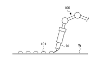
- an adhesive 101 may be applied to a workpiece W such as an outer panel by a robot arm 100 having an application nozzle N attached to the tip. Since the adhesive 101 adheres to the application nozzle N, it is necessary to wipe off the adhesive 101 during the operation.
- Patent Document 1 there is an adhesive wiping device for an application nozzle that wipes off the adhesive adhering to the tip of the coating nozzle by pressing the tip of the coating nozzle against the strip wound around the reel. It is disclosed.
- the entire circumference at the tip of the coating nozzle is not pressed by the belt-like body, but the adhesive adhering to the portion pressed by the belt-like body can be wiped off, but the belt-like body is pressed. It is not possible to wipe off the adhesive adhering to the parts that are not.
- Rotating the coating nozzle around the axis can eliminate the portion that is not pressed by the belt and wipe off all the adhesive. However, this is not possible in the case where the coating nozzle does not rotate around the axis. Further, if a structure in which the coating nozzle rotates around the axis in order to wipe off the adhesive is used, it leads to an increase in the weight and cost of the apparatus, and thus a countermeasure is desired.
- the present invention has been made in view of the above problems, and an object of the present invention is to provide a coating nozzle cleaning method and apparatus capable of cleanly wiping the coating agent adhering to the coating nozzle.
- An application nozzle cleaning device (for example, an application nozzle cleaning device 1 described later) is a cleaning device that cleans the tip of an application nozzle (for example, an application nozzle N described later) capable of translational movement.
- a cleaning pad (for example, a cleaning pad 20 described later) provided with a groove (for example, a groove 21a, 21b, 22a, 22b described later) that allows the application nozzle to be sandwiched, and the groove is a first A first groove portion (for example, first groove portions 21a and 21b to be described later) extending in a direction (for example, a first direction D1 to be described later), and a second direction (to be substantially perpendicular to the first direction) ( For example, it has the 2nd groove part (for example, 2nd groove part 22a, 22b mentioned later) extended in the 2nd direction D2 mentioned later.
- the right and left portions of the application nozzle can be cleaned by sandwiching the application nozzle in the first groove and moving the application nozzle along the first groove.
- the portions located in the front and rear when the first groove portion is cleaned can also be cleaned by sandwiching the application nozzle in the second groove portion and moving the application nozzle along the second groove portion. For this reason, it becomes possible to clean only by the translational movement of the application nozzle. As a result, the coating agent adhering to the coating nozzle can be wiped cleanly while suppressing an increase in the weight and cost of the apparatus.
- the cleaning pad has a plurality of small cleaning pads (for example, small cleaning pads 20A, 20B, 20C, and 20D described later), and the groove portion is formed at a boundary portion between the small cleaning pads. Preferably it is formed.
- the said cleaning pad forms two sets which consist of a said 1st groove part and a said 2nd groove part by combining the four said small cleaning pads, Two said sets, Preferably, the first is for initial cleaning and the second is for final cleaning.
- the replacement span of the entire cleaning pad can be lengthened, and the application nozzle can be cleaned cleanly.
- the present invention provides a base portion (for example, a base portion 11 described later) that supports the cleaning pad from below, and an opening that is attached to the base portion and covers the cleaning pad from above and exposes the groove portion. It is preferable to include a lid (for example, a lid 12 described later) having (for example, a slit 12a described later).
- the coating nozzle cleaning method according to the present invention is a cleaning method for cleaning a tip portion of a translation nozzle (for example, coating nozzle N to be described later) capable of translational movement, and allows the application nozzle to be sandwiched.
- a translation nozzle for example, coating nozzle N to be described later
- a first groove portion for example, first groove portions 21a, 21b described later
- a second groove portion for example, second groove portions 22a and 22b to be described later
- a second direction for example, a second direction D2 to be described later
- a cleaning pad preparation step for example, a cleaning pad preparation step S100 described later for preparing a cleaning pad (for example, a cleaning pad 20 described later), and a front of the application nozzle after the cleaning pad preparation step.
- the application nozzle is moved in the second groove.
- a second cleaning step for example, second cleaning steps S120 and S140, which will be described later moved in the second direction.
- the right and left portions of the application nozzle can be cleaned by sandwiching the application nozzle in the first groove and moving the application nozzle along the first groove.
- the portions located in the front and rear when the first groove portion is cleaned can also be cleaned by sandwiching the application nozzle in the second groove portion and moving the application nozzle along the second groove portion. For this reason, it becomes possible to clean only by the translational movement of the application nozzle. As a result, the coating agent adhering to the coating nozzle can be wiped cleanly while suppressing an increase in the weight and cost of the apparatus.
- the lower end portion of the application nozzle is brought into contact with the cleaning pad and the application nozzle is moved so as to be embedded in the groove portion. It is preferable to make it.
- the lower end portion of the coating nozzle can be well cleaned.
- the cleaning pad forms two sets of the first groove portion and the second groove portion, and the first of the two sets, the first time The first cleaning step and the second cleaning step are performed, and after the first cleaning step and the second cleaning step, the second of the two sets, the second first It is preferable to perform a cleaning process and the second cleaning process.
- finish cleaning can be performed.
- the coating agent adhering to the coating nozzle can be wiped cleanly.
- FIG. 2 is a cross-sectional view showing a coating nozzle cleaning device viewed in the direction of arrow II-II in FIG. 1. It is a flowchart explaining the procedure of the cleaning method of an application nozzle. It is the schematic of the cleaning apparatus of the application nozzle explaining the 1st cleaning process and 2nd cleaning process of the 1st time. It is the schematic of the cleaning apparatus of the application nozzle explaining the 1st cleaning process and the 2nd cleaning process of the 2nd time. It is the schematic of the cleaning apparatus of the application nozzle explaining the movement of the application nozzle in a 1st cleaning process and a 2nd cleaning process. It is a schematic diagram which shows a mode that an adhesive agent is apply
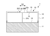
- FIG. 1 is an external perspective view showing a cleaning device 1 for an application nozzle N according to an embodiment of the present invention.
- FIG. 2 is a cross-sectional view showing the cleaning device 1 for the coating nozzle N viewed in the direction of arrows II-II in FIG.
- the coating nozzle N cleaning device 1 cleans the tip of the coating nozzle N that can be translated.
- the coating nozzle N cleaning device 1 is arranged in a moving range of the coating nozzle N that can be moved by a robot arm 100 (see FIG. 7) that is a moving device.
- the cleaning device 1 for the application nozzle N includes a housing 10 and a cleaning pad 20.
- the housing 10 positions the cleaning pad 20 by accommodating the cleaning pad 20.
- the housing 10 includes a base portion 11, a lid portion 12, a pair of hinges 13, a patchon lock (not shown), and anti-slip tapes 14 and 15.
- the base part 11 is a rectangular flat plate that supports the cleaning pad 20 from below.
- An anti-slip tape 14 is attached to the upper surface of the base portion 11, and the cleaning pad 20 is fixed by the anti-slip tape 14.
- the anti-slip tape 14 of the present embodiment is processed so that the surface portion that contacts the cleaning pad 20 is rough.
- a pair of hinges 13 are attached to one side of the base portion 11, and the lid portion 12 is connected to the base portion 11 so as to be openable and closable by the pair of hinges 13.
- a patchon lock (not shown) is attached to the other side portion of the base part 11, and the lid part 12 is fixed to the base part 11 by closing the patchon lock (not shown). By opening (not shown), the lid 12 can be opened with respect to the base 11.
- the lid portion 12 includes an upper plate 16 whose outer shape is rectangular, and a side plate 17 that extends downward from an end side of the upper plate 16.
- An anti-slip tape 15 is attached to the lower surface of the upper plate 16, and the cleaning pad 20 is fixed by the anti-slip tape 15.
- the anti-slip tape 15 of the present embodiment is processed so that the surface portion that contacts the cleaning pad 20 is rough.
- a slit 12a having a cross shape in a plan view is formed from the upper plate 16 to the side plate 17. Grooves 21a, 21b, 22a, 22b in the cleaning pad 20 accommodated in the housing 10 are exposed from the slit 12a.
- a pair of hinges 13 are attached below one side plate 17 of the lid portion 12, and the lid portion 12 is connected to the base portion 11 by the pair of hinges 13 so as to be opened and closed.
- a patchon lock (not shown) is attached below the other side plate 17 of the lid 12, and the lid 12 is fixed to the base 11 by closing the patchon lock (not shown).
- the lid 12 can be opened with respect to the base 11 by opening the patch lock (not shown).
- the cover part 12 is attached to the base part 11, covers the cleaning pad 20 fixed to the base part 11 from above, and has a slit (opening) 12a for exposing the groove parts 21a, 21b, 22a, 22b. .
- Each of the pair of hinges 13 is attached to the base portion 11 and attached to the lid portion 12 on one side of the housing 10, and the lid portion 12 can be opened and closed with respect to the base portion 11 by the pair of hinges 13.
- the patchon lock (not shown) is attached to the base portion 11 and attached to the lid portion 12 on the other side of the housing 10, and is closed with respect to the base portion 11 by closing the patchon lock (not shown). While the part 12 is fixed, the lid part 12 can be opened with respect to the base part 11 by opening the patchon lock (not shown).
- the non-slip tape 14 is attached to the upper surface of the base portion 11 and fixes the cleaning pad 20 to the upper surface of the base portion 11.
- the non-slip tape 15 is attached to the lower surface of the upper plate 16 in the lid portion 12, and fixes the cleaning pad 20 to the lower surface of the upper plate 16. In other words, the cleaning pad 20 is accommodated inside the housing 10 while being sandwiched between the anti-slip tapes 14 and 15.
- the cleaning pad 20 is provided with grooves 21a, 21b, 22a, 22b that allow the application nozzle N to be sandwiched.
- the cleaning pad 20 has a plurality of small cleaning pads 20A, 20B, 20C, and 20D. More specifically, the cleaning pad 20 is a combination of four small cleaning pads 20A, 20B, 20C, and 20D, so that grooves 21a, 21b, 22a, and 22b are formed at the boundary portions of the small cleaning pads 20A, 20B, 20C, and 20D. Form.
- the groove portions 21a, 21b, 22a, and 22b are the first groove portions 21a and 21b extending in the first direction D1, and the second groove portion 22a extending in the second direction D2 that faces in a direction substantially perpendicular to the first direction D1. , 22b.
- the 1st groove part 21a and the 2nd groove part 22a comprise the 1st set used for initial stage cleaning.
- the 1st groove part 21b and the 2nd groove part 22b comprise the 2nd set used for finishing cleaning.
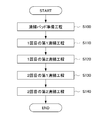
- FIG. 3 is a flowchart for explaining the procedure of the method of cleaning the application nozzle N.
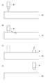
- FIG. 4 is a schematic diagram of the coating nozzle N cleaning device 1 for explaining the first cleaning step S110 and the second cleaning step S120 for the first time.
- FIG. 5 is a schematic diagram of the cleaning device 1 for the application nozzle N for explaining the first cleaning step S130 and the second cleaning step S140 for the second time.
- FIG. 6 is a schematic diagram of the cleaning device 1 for the application nozzle N for explaining the movement of the application nozzle N in the first cleaning steps S110 and S130 and the second cleaning steps S120 and S140. 4 to 6, illustration of the lid 12 is omitted.
- the coating nozzle N cleaning method using the coating nozzle N cleaning device 1 is a method of cleaning the tip of the coating nozzle N that can be translated.
- the cleaning method of the application nozzle N includes a cleaning pad preparation step S100, a first first cleaning step S110, a first second cleaning step S120, and a second first cleaning step. S130 and a second cleaning step S140 for the second time.
- the first groove portions 21a, 21b, 22a, and 22b that can sandwich the application nozzle N are substantially perpendicular to the first direction D1.
- the first first cleaning step S110 is a step of moving the application nozzle N in the first direction D1 within the first groove portion 21a after the cleaning pad preparation step S100.
- the first second cleaning step S120 is a step of moving the application nozzle N in the second direction D2 within the second groove 22a after the first first cleaning step S110. Note that the direction of the application nozzle N itself does not change during the movement in the direction D2.
- the second first cleaning step S130 is a step of moving the application nozzle N in the first direction D1 within the first groove portion 21b after the first second cleaning step S120.
- the second second cleaning step S140 is a step of moving the application nozzle N in the second direction D2 within the second groove 22b after the second first cleaning step S130. Note that the direction of the application nozzle N itself does not change during the movement in the direction D2.
- the application nozzle N When moved only in the D1 direction or moved only in the D2 direction, the application nozzle N advances by pushing the groove portion separately, so both sides of the traveling direction make good contact with the cleaning pad 20, but the front and rear portions in the traveling direction are in contact. It becomes difficult to do. Since the cleaning pad 20 is pushed to both sides as the application nozzle N advances, a gap is formed between the front and rear of the application nozzle N and the cleaning pad 20.
- the process of changing the direction D1 and the direction D2 is included in both the first and second cleanings, and the application nozzle N is moved in two directions.
- the direction is D1
- the portions positioned before and after the traveling direction are positioned on both sides of the traveling direction when the direction is D2. Therefore, by passing through the two directions, the cleaning pad 20 can wipe the entire circumference of the application nozzle N without leakage.
- the coating nozzle N is moved without changing its height.
- the application nozzle N is in a state in which the grooves 21a, 21b, 22a, and 22b are pushed to both sides in the traveling direction inside the grooves 21a, 21b, 22a, and 22b, and a gap is formed between the lower surface of the application nozzle N and the cleaning pad 20. Will be formed. If the coating nozzle N is moved without changing its height, this gap is maintained.
- the lower end portion of the coating nozzle N is inserted into the grooves 21a, 21b, 22a, and 22b from the top to the bottom, so that the lower surface of the coating nozzle N is further improved by the cleaning pad 20 in the process of moving downward. Can be contacted.
- the cleaning device 1 for the application nozzle N has the following effects.
- the application nozzle N is sandwiched between the first grooves 21a and 21b, and the application nozzle N is moved along the first grooves 21a and 21b, thereby cleaning the left and right portions of the application nozzle N. can do.
- the application nozzle N is inserted
- the cleaning pad 20 having the groove portions 21a, 21b, 22a, 22b can be configured with a simple structure.
- the replacement span of the entire cleaning pad 20 can be lengthened, and the coating nozzle N is cleaned. Can be cleaned.
- the lower end portion of the application nozzle N is brought into contact with the cleaning pad 20, and the grooves 21a, 21b, and 22a. , 22b so that the lower end portion of the coating nozzle N can be well cleaned.
- the first cleaning step S110 and the second cleaning step S120 are performed in the first set of the first groove portion 21a and the second groove portion 22a, and the first groove portion 21b and the second groove portion 22b are performed. Finish cleaning can be performed by performing the first cleaning step S130 and the second cleaning step S140 for the second time.
- the second direction D2 in which the second groove portions 22a and 22b extend is substantially perpendicular to the first direction in which the first groove portions 21a and 21b extend.
- the term “concept” includes not only a strict right angle but also a crossing angle that allows the coating agent adhering to the coating nozzle N to be wiped cleanly, and includes, for example, 60 degrees and 70 degrees.
- the lower end portion of the application nozzle N is brought into contact with the cleaning pad 20 and is submerged in the grooves 21a, 21b, 22a, and 22b.
- the application nozzle N is moved as described above, and then the application nozzle N is retreated upward from the cleaning pad 20.
- at least one of the first cleaning steps S110 and S130 and the second cleaning steps S120 and S140 is performed.
- the lower end portion of the application nozzle N is brought into contact with the cleaning pad 20, the application nozzle N is moved so as to enter the groove 21 a, 21 b, 22 a or 22 b, and then the application nozzle N is retreated upward from the cleaning pad 20. You may do it.
- the anti-slip tapes 14 and 15 are arranged above and below the cleaning pad 20, but the anti-slip tapes 14 and 15 are also provided on the inner surface of the lid 12 (the surface facing the side surface of the cleaning pad 20). It is good also as a structure which arranges. Further, the anti-slip tapes 14 and 15 may be omitted.
- the moving device that moves the coating nozzle N is not limited to the robot arm 100. For example, it may be a table mechanism provided with an elevating device that can move the coating nozzle N in the XY plane and move the coating nozzle N in the vertical direction.
Landscapes
- Coating Apparatus (AREA)
- Application Of Or Painting With Fluid Materials (AREA)
Abstract
Description
まず、本実施形態によれば、塗布ノズルNを第1溝部21a,21bに挟み込んで、第1溝部21a,21bに沿うように塗布ノズルNを動かすことで、塗布ノズルNの左右の部分を清掃することができる。また、第1溝部21a,21bによって清掃した際に前後に位置する部分についても、塗布ノズルNを第2溝部22a,22bに挟み込んで、第2溝部22a,22bに沿うように塗布ノズルNを動かすことで清掃することができる。このため、塗布ノズルNの並進移動のみによって清掃することが可能となる。結果、装置の重量増やコスト増を抑制しつつ、塗布ノズルNに付着した塗布剤をキレイに拭き取ることができる。
10 筐体
11 ベース部
12 蓋部
12a スリット(開口)
13 蝶番
14,15 滑り止めテープ
16 上板
17 側板
20 清掃パッド
20A,20B,20C,20D 小清掃パッド
21a,21b 第1溝部(溝部)
22a,22b 第2溝部(溝部)
N 塗布ノズル
D1 第1の方向
D2 第2の方向
S100 清掃パッド準備工程
S110 1回目の第1清掃工程
S120 1回目の第2清掃工程
S130 2回目の第1清掃工程
S140 2回目の第2清掃工程
Claims (7)
- 並進移動可能な塗布ノズルの先端部を清掃する清掃装置であって、
前記塗布ノズルを挟み込み可能とする溝部が設けられる清掃パッドを備え、
前記溝部は、第1の方向に延びる第1溝部と、前記第1の方向に対して略直角の方向に向く第2の方向に延びる第2溝部と、を有する塗布ノズルの清掃装置。 - 前記清掃パッドは、複数の小清掃パッドを有し、
前記溝部は、前記小清掃パッド同士の境界部分に形成される請求項1に記載の塗布ノズルの清掃装置。 - 前記清掃パッドは、4つの前記小清掃パッドを組み合わせることで、前記第1溝部及び前記第2溝部からなるセットを2つ形成するものであり、
2つの前記セットは、1つ目が初期清掃用であり、2つ目が仕上げ清掃用である請求項2に記載の塗布ノズルの清掃装置。 - 前記清掃パッドを下方より支持するベース部と、
前記ベース部に取り付けられ、前記清掃パッドを上方から覆うと共に、前記溝部を露出させる開口を有する蓋部と、を備える請求項1~3のいずれかに記載の塗布ノズルの清掃装置。 - 並進移動可能な塗布ノズルの先端部を清掃する清掃方法であって、
前記塗布ノズルを挟み込み可能とする溝部として、第1の方向に延びる第1溝部と、前記第1の方向に対して略直角の方向に向く第2の方向に延びる第2溝部と、を有する清掃パッドを準備する清掃パッド準備工程と、
前記清掃パッド準備工程の後に、前記塗布ノズルを前記第1溝部内で前記第1の方向に移動させる第1清掃工程と、
前記第1清掃工程の後に、前記塗布ノズルを前記第2溝部内で前記第2の方向に移動させる第2清掃工程と、を備える塗布ノズルの清掃方法。 - 前記第1清掃工程及び前記第2清掃工程の少なくとも1つにおいて、前記塗布ノズルの下端部分を前記清掃パッドに接触させ、前記溝部に潜り込ませるように前記塗布ノズルを移動させる請求項5に記載の塗布ノズルの清掃方法。
- 前記清掃パッドは、前記第1溝部及び前記第2溝部からなるセットを2つ形成するものであり、
2つの前記セットのうちの1つ目にて、1回目の前記第1清掃工程及び前記第2清掃工程を行い、
前記1回目の前記第1清掃工程及び前記第2清掃工程の後に、2つの前記セットのうちの2つ目にて、2回目の前記第1清掃工程及び前記第2清掃工程を行う請求項5又は6に記載の塗布ノズルの清掃方法。
Priority Applications (5)
| Application Number | Priority Date | Filing Date | Title |
|---|---|---|---|
| US17/050,452 US20210237115A1 (en) | 2018-05-11 | 2019-05-08 | Coating nozzle cleaning method and device |
| CN201980030576.3A CN112074352B (zh) | 2018-05-11 | 2019-05-08 | 涂布喷嘴的清洁方法和装置 |
| BR112020021147-8A BR112020021147A2 (pt) | 2018-05-11 | 2019-05-08 | método e dispositivo de limpeza do bico de revestimento |
| CA3097022A CA3097022C (en) | 2018-05-11 | 2019-05-08 | Coating nozzle cleaning method and device |
| JP2020518312A JP6964189B2 (ja) | 2018-05-11 | 2019-05-08 | 塗布ノズルの清掃方法及び装置 |
Applications Claiming Priority (2)
| Application Number | Priority Date | Filing Date | Title |
|---|---|---|---|
| JP2018-092047 | 2018-05-11 | ||
| JP2018092047 | 2018-05-11 |
Publications (1)
| Publication Number | Publication Date |
|---|---|
| WO2019216334A1 true WO2019216334A1 (ja) | 2019-11-14 |
Family
ID=68467094
Family Applications (1)
| Application Number | Title | Priority Date | Filing Date |
|---|---|---|---|
| PCT/JP2019/018346 Ceased WO2019216334A1 (ja) | 2018-05-11 | 2019-05-08 | 塗布ノズルの清掃方法及び装置 |
Country Status (6)
| Country | Link |
|---|---|
| US (1) | US20210237115A1 (ja) |
| JP (1) | JP6964189B2 (ja) |
| CN (1) | CN112074352B (ja) |
| BR (1) | BR112020021147A2 (ja) |
| CA (1) | CA3097022C (ja) |
| WO (1) | WO2019216334A1 (ja) |
Citations (5)
| Publication number | Priority date | Publication date | Assignee | Title |
|---|---|---|---|---|
| JP2007275794A (ja) * | 2006-04-07 | 2007-10-25 | Seiko Epson Corp | ワイピング装置、ワイピング装置の運転方法およびワイピング方法、並びに液滴吐出装置、電気光学装置の製造方法、電気光学装置および電子機器 |
| JP2007283240A (ja) * | 2006-04-18 | 2007-11-01 | Komuratekku:Kk | クリーニングパッド |
| JP2009018261A (ja) * | 2007-07-12 | 2009-01-29 | Tokyo Ohka Kogyo Co Ltd | ノズル洗浄装置、ノズル洗浄方法、塗布装置及び塗布方法 |
| JP2012135918A (ja) * | 2010-12-26 | 2012-07-19 | Ricoh Co Ltd | ヘッド回復装置及び画像形成装置 |
| JP2015033679A (ja) * | 2013-08-09 | 2015-02-19 | 東京エレクトロン株式会社 | プライミング処理方法、塗布処理装置、プログラム及びコンピュータ記憶媒体 |
Family Cites Families (5)
| Publication number | Priority date | Publication date | Assignee | Title |
|---|---|---|---|---|
| JP3645586B2 (ja) * | 1994-06-08 | 2005-05-11 | 大日本スクリーン製造株式会社 | 処理液塗布装置 |
| JP5399053B2 (ja) * | 2008-11-26 | 2014-01-29 | 株式会社アドテックス | インクジェット塗布装置のノズルヘッド洗浄装置、これを備えたインクジェット塗布装置のノズルワイピング装置 |
| JP5701822B2 (ja) * | 2012-06-20 | 2015-04-15 | 東レエンジニアリング株式会社 | 洗浄装置および洗浄方法 |
| CN103846183A (zh) * | 2013-12-20 | 2014-06-11 | 深圳市华星光电技术有限公司 | 一种涂布机喷嘴清洁装置 |
| CN106824680B (zh) * | 2017-03-20 | 2019-12-20 | 合肥京东方光电科技有限公司 | 一种用于狭缝喷嘴的排废液槽及狭缝喷嘴清洗装置 |
-
2019
- 2019-05-08 BR BR112020021147-8A patent/BR112020021147A2/pt not_active Application Discontinuation
- 2019-05-08 CA CA3097022A patent/CA3097022C/en active Active
- 2019-05-08 US US17/050,452 patent/US20210237115A1/en not_active Abandoned
- 2019-05-08 CN CN201980030576.3A patent/CN112074352B/zh not_active Expired - Fee Related
- 2019-05-08 WO PCT/JP2019/018346 patent/WO2019216334A1/ja not_active Ceased
- 2019-05-08 JP JP2020518312A patent/JP6964189B2/ja not_active Expired - Fee Related
Patent Citations (5)
| Publication number | Priority date | Publication date | Assignee | Title |
|---|---|---|---|---|
| JP2007275794A (ja) * | 2006-04-07 | 2007-10-25 | Seiko Epson Corp | ワイピング装置、ワイピング装置の運転方法およびワイピング方法、並びに液滴吐出装置、電気光学装置の製造方法、電気光学装置および電子機器 |
| JP2007283240A (ja) * | 2006-04-18 | 2007-11-01 | Komuratekku:Kk | クリーニングパッド |
| JP2009018261A (ja) * | 2007-07-12 | 2009-01-29 | Tokyo Ohka Kogyo Co Ltd | ノズル洗浄装置、ノズル洗浄方法、塗布装置及び塗布方法 |
| JP2012135918A (ja) * | 2010-12-26 | 2012-07-19 | Ricoh Co Ltd | ヘッド回復装置及び画像形成装置 |
| JP2015033679A (ja) * | 2013-08-09 | 2015-02-19 | 東京エレクトロン株式会社 | プライミング処理方法、塗布処理装置、プログラム及びコンピュータ記憶媒体 |
Also Published As
| Publication number | Publication date |
|---|---|
| JPWO2019216334A1 (ja) | 2021-04-22 |
| CA3097022A1 (en) | 2019-11-14 |
| CN112074352A (zh) | 2020-12-11 |
| BR112020021147A2 (pt) | 2021-02-17 |
| US20210237115A1 (en) | 2021-08-05 |
| CN112074352B (zh) | 2022-09-20 |
| JP6964189B2 (ja) | 2021-11-10 |
| CA3097022C (en) | 2022-12-06 |
Similar Documents
| Publication | Publication Date | Title |
|---|---|---|
| TWI489198B (zh) | 防塵薄膜組件處理用治具 | |
| JPWO2009119348A1 (ja) | レンズ保持具、レンズ保持方法およびレンズ処理方法 | |
| TW201437030A (zh) | 剝離裝置及剝離方法 | |
| JP2018040045A (ja) | 基板ホルダ、めっき装置、及び基板を保持する方法 | |
| CN101362123A (zh) | 喷嘴清洗装置及清洗方法 | |
| JP3462657B2 (ja) | 薄膜形成装置および薄膜形成方法 | |
| JP2016071250A (ja) | 電極付き基板 | |
| WO2019216334A1 (ja) | 塗布ノズルの清掃方法及び装置 | |
| JP6920046B2 (ja) | フィルム切断用治具、及びフィルム施工方法 | |
| KR102070074B1 (ko) | 펠리클 프레임 | |
| KR101926348B1 (ko) | 곡면 테두리부가 형성된 휴대폰 커버글라스의 표면 스크래치 제거방법 | |
| WO2016148226A1 (ja) | 端面クリーナ | |
| CN105149294B (zh) | 一种除尘设备 | |
| TW201834136A (zh) | 基板固持器、鍍覆裝置、鍍覆方法、及電氣接點 | |
| JP6768495B2 (ja) | 基板ホルダ、めっき装置、及びめっき方法 | |
| JPH1152583A5 (ja) | ||
| KR20120040340A (ko) | 딥 코팅 장치 | |
| JPH10319251A (ja) | 光ファイバテープの単心分離工具 | |
| JPH08117704A (ja) | 洗浄装置のシャッター | |
| TWI705519B (zh) | 基板處理裝置、基板處理方法、光罩洗淨方法及光罩製造方法 | |
| CN219314860U (zh) | 一种可进行屏幕清理的手机保护膜 | |
| WO2015166566A1 (ja) | 塗布装置及び塗布方法 | |
| KR102859593B1 (ko) | 자개 문양 휴대폰 케이스 제조 방법 | |
| KR20210002182A (ko) | 노즐 세정 유닛 및 기판 처리 장치 | |
| CN214164602U (zh) | 一种艺术设计用多功能绘图装置 |
Legal Events
| Date | Code | Title | Description |
|---|---|---|---|
| 121 | Ep: the epo has been informed by wipo that ep was designated in this application |
Ref document number: 19799126 Country of ref document: EP Kind code of ref document: A1 |
|
| ENP | Entry into the national phase |
Ref document number: 2020518312 Country of ref document: JP Kind code of ref document: A |
|
| ENP | Entry into the national phase |
Ref document number: 3097022 Country of ref document: CA |
|
| REG | Reference to national code |
Ref country code: BR Ref legal event code: B01A Ref document number: 112020021147 Country of ref document: BR |
|
| NENP | Non-entry into the national phase |
Ref country code: DE |
|
| ENP | Entry into the national phase |
Ref document number: 112020021147 Country of ref document: BR Kind code of ref document: A2 Effective date: 20201015 |
|
| 122 | Ep: pct application non-entry in european phase |
Ref document number: 19799126 Country of ref document: EP Kind code of ref document: A1 |