WO2019216255A1 - ミシン目付きシート材 - Google Patents
ミシン目付きシート材 Download PDFInfo
- Publication number
- WO2019216255A1 WO2019216255A1 PCT/JP2019/017797 JP2019017797W WO2019216255A1 WO 2019216255 A1 WO2019216255 A1 WO 2019216255A1 JP 2019017797 W JP2019017797 W JP 2019017797W WO 2019216255 A1 WO2019216255 A1 WO 2019216255A1
- Authority
- WO
- WIPO (PCT)
- Prior art keywords
- sheet material
- perforation
- perforated sheet
- perforations
- hole
- Prior art date
- Legal status (The legal status is an assumption and is not a legal conclusion. Google has not performed a legal analysis and makes no representation as to the accuracy of the status listed.)
- Ceased
Links
Images






Classifications
-
- B—PERFORMING OPERATIONS; TRANSPORTING
- B65—CONVEYING; PACKING; STORING; HANDLING THIN OR FILAMENTARY MATERIAL
- B65D—CONTAINERS FOR STORAGE OR TRANSPORT OF ARTICLES OR MATERIALS, e.g. BAGS, BARRELS, BOTTLES, BOXES, CANS, CARTONS, CRATES, DRUMS, JARS, TANKS, HOPPERS, FORWARDING CONTAINERS; ACCESSORIES, CLOSURES, OR FITTINGS THEREFOR; PACKAGING ELEMENTS; PACKAGES
- B65D23/00—Details of bottles or jars not otherwise provided for
- B65D23/08—Coverings or external coatings
-
- B—PERFORMING OPERATIONS; TRANSPORTING
- B65—CONVEYING; PACKING; STORING; HANDLING THIN OR FILAMENTARY MATERIAL
- B65D—CONTAINERS FOR STORAGE OR TRANSPORT OF ARTICLES OR MATERIALS, e.g. BAGS, BARRELS, BOTTLES, BOXES, CANS, CARTONS, CRATES, DRUMS, JARS, TANKS, HOPPERS, FORWARDING CONTAINERS; ACCESSORIES, CLOSURES, OR FITTINGS THEREFOR; PACKAGING ELEMENTS; PACKAGES
- B65D25/00—Details of other kinds or types of rigid or semi-rigid containers
- B65D25/20—External fittings
Definitions
- the present invention relates to a perforated sheet material and a package including the perforated sheet material.
- Patent Document 1 discloses a package in which a shrink film is attached around an article. A perforation is formed in the shrink film, and when the article is used, the perforation is broken to remove the shrink film from the article.
- the present invention has been made to solve the above-described problems, and an object of the present invention is to provide a perforated sheet material having a perforation that is more easily broken, and a package including the perforated sheet material.
- the perforated sheet material according to the present invention includes a sheet material and at least a pair of through holes arranged in the sheet material at a predetermined interval on a line extending in the first direction and penetrating the sheet material.
- Each perforation is configured to be broken from one end portion in the first direction toward the other end portion, and the distance between the pair of perforations is the other end side. It is formed to become narrower as it goes to.
- At least some of the plurality of through holes can be configured to open in a second direction orthogonal to the first direction.
- the perforation when the perforation is broken along the first direction, even if the force is slightly deviated, the through hole is open in the second direction, so that the force deviation from the first direction is penetrated. Can act on the pores. Therefore, the perforation can be easily broken.
- the first direction and the second direction do not have to be strictly orthogonal, and may be slightly shifted as long as the through hole is open.
- At least a part of the plurality of through holes can be formed in an arc shape at a portion facing the adjacent through hole.
- the width of the through hole in the second direction becomes smaller as it approaches the adjacent through hole. Therefore, it is possible to guide the force acting on the through hole to the narrow part in the through hole, that is, the position closest to the adjacent through hole in accordance with the break of the perforation. Therefore, the perforation can be broken more easily.
- the perforation is configured to be broken from one end portion in the first direction toward the other end portion, and the plurality of through holes are a plurality of openings opened in the second direction.
- a first through hole group including a through hole, and a second through hole group disposed on the other end side of the first through hole group and including the plurality of linearly formed through holes.
- the through-holes of the first through-hole group can be formed so that the width in the second direction decreases as going to the other end side.
- the width of the through hole in the first through hole group in the second direction becomes narrower, and the breakage extends to the adjacent end portion of the adjacent through hole in each through hole. Since the force is easily induced, the breaking line can be made to follow the stranded line. Therefore, after the rupture of the first through hole group is completed, the force related to the rupture can be easily induced to the second through hole group including the linear through hole. Therefore, even a perforation having a linear through hole such as the second through hole group can be easily broken.
- a tension can be applied to the sheet material in the second direction orthogonal to the first direction.
- the tension can be increased on the other end side than on the one end side.
- the package according to the present invention includes an article having a surface to be packaged and any of the above-mentioned perforated sheet material attached to cover the surface to be packaged in a state where tension is applied in a predetermined direction.
- the perforated sheet material is attached so that the first direction is perpendicular to the direction in which the tension acts, and the first direction of the perforated sheet material attached to the surface of the article to be packaged
- the perforated sheet material has a pair of perforations extending across the protrusion.
- the tension is further applied to the perforated sheet material by the protrusion, the tension is easily applied to the opposite sides across the protrusion, so that the perforation on both sides of the protrusion is penetrated.
- a force that opens them in the second direction acts on the holes. Therefore, the perforation can be easily broken.
- the first direction may not be strictly perpendicular to the direction in which the tension acts, and may be slightly shifted as long as the above effect can be obtained.
- recesses are formed at predetermined intervals along the first direction on the surface to be packaged of the article, and the perforated sheet material is a position where the perforations pass over the recesses. It can be configured to be arranged.
- the convex portion between the concave portions supports the sheet material and can relieve the tension. As a result, it is possible to prevent the perforation from breaking unexpectedly.
- the perforation can be more easily broken.
- FIG. 13 It is a top view which shows one Embodiment of the sheet material with a perforation which concerns on this invention. It is a top view which shows the other example of FIG. It is a top view which shows the other example of FIG. It is a top view which shows the other example of FIG. It is a top view which shows the other example of FIG. It is a top view which shows the other example of FIG. It is a top view which shows the other example of FIG. It is a top view which shows the other example of FIG. It is a top view which shows the other example of FIG. It is a front view which shows one Embodiment of the articles
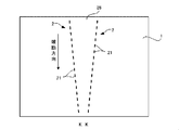
- FIG. 1 is a plan view of the perforated sheet material.
- the perforated sheet material 10 includes a sheet material 1 and a pair of perforations 2 formed on the sheet material 1.
- the perforated sheet material 10 is used, for example, for packaging an article, and then the pair of perforations 2 is broken, and the sheet material 1 is removed from the article by cutting a cut region 28 between them. Can do.
- the perforation is broken from the upper end (one end) in FIG. 1 toward the lower end (the other end). That is, the direction from the upper end to the lower end in FIG.
- a direction parallel to the breaking direction is referred to as a first direction
- a direction orthogonal to the first direction is referred to as a second direction. Details will be described below.
- the sheet material 1 can be formed of paper, a resin material, or the like.
- the resin material for example, polystyrene, polyethylene terephthalate, polypropylene, polyvinyl chloride, or a material containing a plurality of these can be employed.
- the sheet material 1 can be a shrink film that shrinks by heat, and can be used as the sheet material 1 that is packaged in close contact with the outer peripheral surface of the article.
- the thickness of the sheet material 1 is not particularly limited, but is preferably 35 to 60 ⁇ m, for example, and more preferably 40 to 55 ⁇ m.
- the sheet material 1 when the sheet material 1 is not used to cover the article but is used as a material constituting a container such as a box or the article itself, a sheet material (for example, paper) having a basis weight of 250 to 450 g / m 2 should be used. Is preferred.
- the pair of perforations 2 are formed so as to be inclined with respect to each other so that the distance between the two perforations 2 becomes narrower toward the downstream side in the breaking direction.
- L is a line along the direction in which each perforation 2 extends.
- Each perforation 2 is constituted by a plurality of through holes 21 arranged on the line L at a predetermined interval.
- the direction in which the perforation 2 extends is referred to as a first direction, and the direction orthogonal thereto is referred to as a second direction.
- the through hole 21 will be described.
- the through hole 21 can take various forms.
- at least a pair of perforations 2 are required to form the cut-out region 28, but in the following, only one perforation 2 is shown and described for explaining the through hole 21.
- only one perforation 2 is shown and described for explaining the through hole 21.
- the through hole 21 is formed in a linear shape along the line L.
- the through hole is closed.
- the plurality of through holes 21 are open in a second direction orthogonal to the first direction.
- the shape of the through hole 21 is not particularly limited as long as it is open in the second direction.
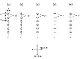
- a circle (a) an ellipse (b) having a major axis in the first direction
- Various shapes such as an ellipse (c) having a major axis in the second direction, a linear shape (d) extending in the second direction, a rectangular shape (e), or a combination of these shapes can be used.
- the inner diameters A and B of the through holes 21 in the first direction and the second direction are preferably 0.3 to 1.0 mm, and more preferably 0.5 to 1.0 mm. . Either of the inner diameters A and B may be long or the same length. Further, the interval C between the through holes 21 is preferably 0.3 to 1.0 mm, and more preferably 0.5 to 1.0 mm. Further, the ratio of the length between the inner diameter A (B) of the through hole and the distance C is preferably 1: 0.5 to 1: 1.3, and is 1: 0.5 to 1: 1.2. More preferably, it is 1: 0.5 to 1: 1.0. This dimension can be applied to all through holes opened in the second direction in this specification.
- the perforation 2 is configured in this way, when the perforation 2 is broken along the first direction, the through-hole 21 is open in the second direction even if the force slightly deviates from the line L. Therefore, a force shift can be applied in the through hole 21. Therefore, the perforation 2 can be broken even if the force does not strictly act on the line L. Therefore, the breaking operation of the perforation 2 can be easily performed.
- the width of the through hole 21 in the second direction becomes smaller as the adjacent through hole 21 is approached. Therefore, as shown in FIG. 4, the force acting on the through hole 21 due to the break of the perforation 2 is applied to a narrow portion of the through hole 21, that is, the adjacent through hole 21, as indicated by a line S. It is possible to guide smoothly to the nearest location G. Therefore, the perforation 2 can be broken more easily.
- the perforated sheet material may not have all the through holes 21 having the same size.
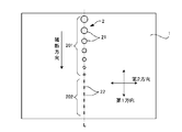
- the first perforated sheet material has a plurality of through holes 21 spreading in the second direction as described above.
- variety of the 2nd direction of the through-hole 21 is narrowing as it goes to a fracture
- a second through hole group 202 is arranged following the through hole 21 having the narrowest width in the second direction.
- the width of the through hole 21 in the second direction becomes narrower, and in each through hole, the end G close to the adjacent through hole is broken. Since it is easy to induce such a force, the break line can be guided along the stranded line L. Therefore, after the breakage of the first through-hole group 201 is finished, the force related to the breakage can be easily guided to the second through-hole group 202 including the linear through-hole 22. Therefore, even a perforation having a narrow width like the second through-hole group 202 can be easily broken.
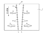
- the form of the through hole 21 may be any of the above aspects 1 to 4, but as shown in FIG. 6, a tension can be applied to the sheet material 1 in the second direction. Thereby, tension can be applied to the through holes in directions opposite to each other across the line L.
- the package according to this embodiment is obtained by packaging a chemical volatilizer (article) with a shrink film to which the configuration of the perforated sheet material is applied. First, the chemical volatilizer will be described.
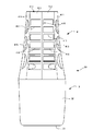
- FIG. 8 is a front view of the chemical volatilizer
- FIG. 9 is a side view of FIG.
- the drug volatilizer 30 includes a resin container 3 that stores a chemical such as a fragrance, and a resin cover member 4 that is detachably attached to the upper part of the container 3.
- the near side and the far side of the sheet of FIG. 8 are referred to as the front side and the back side, respectively, and the left and right sides of FIG. 8 are referred to as the side surfaces.
- FIG. 10 is a front view of the container
- FIG. 11 is a side view of FIG.
- the container 3 includes an upper part 31 having an opening, a body part 32 that continues to the upper part 31 and extends downward, and a bottom part 33 that closes the lower part of the body part 32. These form an internal space. And in this internal space, liquid medicines, such as a fragrance
- the upper portion 31 has a cylindrical neck portion 311 to which the lid portion 38 is attached, and a cylindrical opening (not shown) is formed at the upper end of the neck portion 311.
- a screw groove (not shown) is formed on the periphery of the opening, and a lid portion 38 that closes the opening can be detachably attached.
- a volatilizing body (not shown) impregnated with a drug is attached to the lower surface of the lid portion 38. This volatilized body is accommodated in the internal space until the lid portion 38 is opened, and is impregnated with the drug. And after removing the cover part 38 from the neck part 311, a volatilization body can be pulled up and it can expose now.
- a shoulder 312 having an elliptical shape in plan view is provided at the lower end of the neck 311.
- the shoulder portion 312 connects the upper surface portion 3121 extending substantially horizontally continuously from the lower end of the neck portion 311, the side surface portion 3122 extending continuously downward from the upper surface portion 3121, the side surface portion 3122, and the body portion 12. And a stepped portion 3123.
- the side surface portion 3122 is formed with a concave portion 3124 extending along the circumferential direction.
- the concave portion 3124 is also for fitting a protrusion (not shown) provided on the cover member 4 when the cover member 4 is attached to the container 3.
- the body 32 is connected to the lower end of the shoulder 312.
- the body portion 32 is formed in a cylindrical shape, and the lower end thereof is closed by the bottom portion 33.
- the cover member 4 includes a cylindrical main body portion 41 and a circular top surface portion 42 that closes the upper opening of the main body portion 41. Is formed.
- the main body 41 is formed in a cylindrical shape by connecting a pair of first panels 411 arranged on the front side and the back side, respectively, and a pair of second panels 412 arranged on both sides thereof. .
- the first panel 411 has a plurality of openings 415, and the internal space of the main body 41 communicates with the outside through the openings 415.
- the second panel 412 includes a rib 416 extending in the vertical direction, and a pair of plate-like panel pieces 413 extending between the rib 416 and the boundary between the first panels 411. ing.
- the rib 416 extends so as to be slightly curved from above to below. That is, as shown in FIG. 8, the lower end of the rib 416 is located slightly radially outward from the center of the main body 41 than the upper end of the rib 416 and is convex toward the internal space of the main body 41. It is slightly curved to be.
- Both panel pieces 413 are connected at an angle via ribs 416.
- the panel piece 413 is formed with a plurality of rectangular openings 417 arranged in the vertical direction, and the internal space of the main body 41 communicates with the outside through the openings 417.
- a bar-like connecting piece 418 is formed between the openings 417 adjacent to each other in the vertical direction.
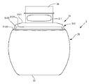
- FIG. 12 is a front view of the package
- FIG. 13 is a side view of FIG. 12
- FIG. 14 is a plan view of FIG.
- the shrink film 7 is formed of the same material as the sheet material 1 described above, and is attached so as to be in close contact with almost the entire outer peripheral surface of the drug volatilizer 30. That is, as shown in FIG. 14, the shrink film 7 passes from the peripheral portion of the top surface portion 42 of the cover member 4 to the outer peripheral surface of the main body portion 41 of the cover member 4 as shown in FIGS. 12 and 13. 3 to the lower end of the body 32.
- These first to third portions 71 to 73 are integrally formed.
- part 71 is formed with a pair of 1st perforation 81 in substantially parallel. That is, both the first perforations 81 extend radially outward from the inner edge to the outer edge of the first portion 71.
- a pair of second perforations 82 are formed in the second portion 72 so as to be continuous with the first perforations 81 and extend slightly below the boundary with the third portion 73.
- a third perforation that extends in the circumferential direction over the entire circumference of the body portion 32 of the container 3 passes through the lower ends of the second perforations 82 and slightly below the boundary between the second portion 72 and the third portion 73.
- 83 is formed.
- a region between both first perforations 81 forms a first cut region 701
- a region between both second perforations 82 forms a second cut region 702.
- the first and second cutout regions 701 and 702 are integrally connected.
- a region surrounded by the first and second cut regions 701 and 702 and the third perforation 83 is referred to as a cover region 703.
- the distance between the pair of second perforations 82 decreases as it goes downward as described in the above-described embodiment of the perforated sheet material.
- the through hole may be any one of the above-described embodiments 1 to 6.
- the configuration of the first perforation and the third perforation is not particularly limited.
- both the second perforations 82 are arranged on both sides with the rib 416 interposed therebetween, the rib 416 acts as a protrusion, and a tension acts on each second perforation 82 in the circumferential direction. Further, since the rib 416 is curved so as to be located radially outward as it goes downward, the tension acting in the circumferential direction increases as the second perforation 82 goes downward. It has become.
- the shrink film 7 is disposed on both sides of the rib 416 so as to cover the plurality of openings 417. That is, on both sides of the rib 416, the openings 417 and the connecting pieces 418 are alternately arranged in the vertical direction (it can be said that the unevenness is alternately arranged).
- the opening 417 does not contact the shrink film 7 and a large tension acts as described above.
- the connecting piece 418 contacts the shrink film 7, a large tension does not act. Therefore, in the second perforation 82, a large force acts on the portion corresponding to the opening 417 and is easily broken, but on the other hand, a large force does not act on the portion in contact with the connection 418 piece, so that it is easy. Breakage can be suppressed. Therefore, with this configuration, both ease of breakage and prevention of unexpected breakage can be achieved.
- the articles to be wrapped with the shrink film can be various, and can naturally be applied to articles such as various containers and boxes other than the fragrance according to the above embodiment.
- the shape of the shrink film that is, the shape and size of the portion covered with the shrink film is not particularly limited.
- the perforations provided in the shrink film may be appropriately designed according to the method for removing the shrink film, and can be applied as described in the above ⁇ 1>.
- ⁇ 3> when attaching a perforated sheet material such as a shrink film to an article, as described above, it is preferable to arrange perforations on both sides of the rib 416 in order to increase the tension, but the present invention is not limited to this. That is, in addition to providing protrusions such as ribs 416 on the outer peripheral surface of the article, it covers sharp corners or arc-shaped corners having a small radius of curvature so that tension is easily applied to the shrink film. If the sheet material is wound as described above and perforations are arranged on both sides of the sheet material, the sheet material is easily broken. Note that the sheet material is not limited to the shrink film 7 and may be a sheet material on which tension is applied.
- the cover member 4 is configured so that the diameter of the cover member 4 increases as it goes downward, so that the tension increases with respect to the shrink film 7, but the present invention is not limited to this. That is, as the tension increases as it goes in the breaking direction or on the downstream side in the breaking direction, for example, the outer diameter of the cover member 4 is made constant, and the inner diameter of the shrink film 7 is set in the breaking direction. It is possible to increase the tension acting on the shrink film 7 in accordance with the reduction in advance on the downstream side.
- the shape is not particularly limited as long as the shape can change the tension. It should be noted that such a change in tension does not occur, and the tension may be substantially constant in the breaking direction.
- the opening 417 is formed at a predetermined interval in the article, and the shrink film 7 is formed by the connecting piece 418 between the openings 417.
- the present invention is not limited to this.
- an opening other than a rectangular shape may be used.
- it may not be the opening part 417, and the recessed part which does not contact the shrink film 7 may be sufficient.
- it can also comprise so that a convex part may be provided at predetermined intervals, the shrink film 7 may be supported by the convex part, and the concave part between them may not contact the shrink film 7.
- the direction in which the recesses are arranged is not necessarily the vertical direction, and may be arranged at a predetermined interval in the first direction in which the perforation extends.
- the sheet material is not limited to the shrink film 7 and may be a sheet material on which tension is applied.
- the perforated sheet material according to the present invention can be applied to other than the shrink film for packaging the article, and can also be used as a packaging material for simply packaging the article without shrinking. That is, it is only necessary that the sheet material is attached to the article with tension in a predetermined direction. And the 1st direction of a perforation should just be set so that it may be substantially orthogonal to the direction where this tension acts. The tension does not have to be applied, it may simply be covered.
- the perforated sheet material according to the present invention can be used as a material constituting a container such as a box or the article itself.
Landscapes
- Engineering & Computer Science (AREA)
- Mechanical Engineering (AREA)
- Packages (AREA)
- Details Of Rigid Or Semi-Rigid Containers (AREA)
- Wrappers (AREA)
Abstract
【課題】より破断しやすいミシン目を有するミシン目付きシート材、及びこれを備えた包装体を提供する。 【解決手段】本発明に係るミシン目付きシート材は、シート材と、前記シート材において、第1方向に延びる線上に所定間隔をおいて並び、前記シート材を貫通する複数の貫通孔によって構成された少なくとも一対のミシン目と、を備え、前記各ミシン目は、前記第1方向の一端部から他端部に向けて破断されるように構成され、前記一対のミシン目の間の距離が、他端部側にいくにしたがって、狭くなるように形成されている。
Description
本発明は、ミシン目付きシート材、及びこれを備えた包装体に関する。
特許文献1には、物品の周囲にシュリンクフィルムを取り付けた包装体が開示されている。シュリンクフィルムには、ミシン目が形成されており、物品を使用する際には、ミシン目を破断して、シュリンクフィルムを物品から取り外すように構成されている。
しかしながら、ミシン目の破断には、改良の余地があり、さらに破断しやすいミシン目が要望されていた。本発明は、上記問題を解決するためになされたものであり、より破断しやすいミシン目を有するミシン目付きシート材、及びこれを備えた包装体を提供することを目的とする。
本発明に係るミシン目付きシート材は、シート材と、前記シート材において、第1方向に延びる線上に所定間隔をおいて並び、前記シート材を貫通する複数の貫通孔によって構成された少なくとも一対のミシン目と、を備え、前記各ミシン目は、前記第1方向の一端部から他端部に向けて破断されるように構成され、前記一対のミシン目の間の距離が、他端部側にいくにしたがって、狭くなるように形成されている。
この構成によれば、例えば、両ミシン目の間の切り取り領域を引っ張って、一端部側から他端部側へ向かってミシン目を破断させると、この力を両ミシン目の間に集中させやすくなる。そのため、切り取り領域を引っ張る力が、両ミシン目よりも外側に向くことを防止することができる。したがって、切り取り領域の内部あるいはミシン目に沿って、力を作用させやすくなり、ミシン目の破断を容易に行うことができる。
上記ミシン目付きシート材においては、前記複数の貫通孔のうち、少なくとも一部の複数の貫通孔が、前記第1方向と直交する第2方向に開くように構成することができる。
この構成によれば、第1方向に沿ってミシン目を破断するとき、その力が多少ずれたとしても、貫通孔が第2方向に開いているため、第1方向のから力のずれを貫通孔に作用させることができる。そのため、ミシン目を破断させやすくすることができる。なお、第1方向と第2方向とは厳密に直交していなくてもよく、貫通孔が開くような方向であれば、多少ずれていてもよい。
上記ミシン目付きシート材においては、前記複数の貫通孔のうち、少なくとも一部の複数の貫通孔は、隣接する貫通孔と向き合う部分が円弧状に形成することができる。
この構成によれば、隣接する貫通孔と向き合う部分が円弧状に形成されているため、貫通孔の第2方向の幅は、隣接する貫通孔に近づくにつれて小さくなる。そのため、ミシン目の破断にともなって、貫通孔に作用した力を貫通孔における幅の狭い部分、つまり隣接する貫通孔に最も近い箇所まで誘導することができる。したがって、ミシン目の破断をさらに容易に行うことができる。
上記ミシン目付きシート材において、前記ミシン目は、前記第1方向の一端部から他端部に向けて破断されるように構成され、前記複数の貫通孔は、前記第2方向に開いた複数の貫通孔を含む第1貫通孔群と、前記第1貫通孔群の前記他端部側に配置され、前記線状に形成された複数の貫通孔を含む第2貫通孔群と、を有し、前記第1貫通孔群の貫通孔は、前記他端部側にいくにしたがって、前記第2方向の幅が小さくなるように形成することができる。
この構成によれば、ミシン目の破断が進行するにつれて、第1貫通孔群における貫通孔の第2方向の幅が狭くなり、各貫通孔において隣接する貫通孔の近接する端部まで破断に係る力を誘導しやすくなっているため、破断線を、より線に沿わせるようにすることができる。そのため、第1貫通孔群の破断が終了した後、破断に係る力を、線状の貫通孔を含む第2貫通孔群に容易に誘導することができる。したがって、第2貫通孔群のような線状の貫通孔を有するミシン目であっても、破断を容易に行うことができる。
上記ミシン目付きシート材において、前記シート材には、前記第1方向と直交する前記第2方向にテンションを作用させることができる。
第2方向に作用するテンションにより、ミシン目の各貫通孔には、これらを第2方向に開くような力が作用する。そのため、ミシン目の破断に係る力を貫通孔に作用させやすくなり、ミシン目を容易に破断させることができる。
上記ミシン目付きシート材では、前記一端部側よりも他端部側において前記テンションを大きくすることができる。
この構成によれば、他端部側においてテンションが大きいため、破断が進んだ他端部側において、ミシン目を破断させやすくなる。そのため、次のような利点がある。すなわち、ミシン目の破断が進むと、既に切り取られた切り取り領域の長さが長くなり、切り取り領域を引っ張る力を作用させがたくなり、また、ミシン目に沿って破断させにくくなる(切り取り領域が長くなるのでコントロールしにくくなる)。このような場合、他端部側においてテンションが大きいと、切り取り領域の長さが長くなっても、ミシン目の破断を容易に行うことができる。
本発明に係る包装体は、被包装面を有する物品と、前記被包装面に所定の方向にテンションが作用した状態で、覆うように取り付けられる、上述したいずれかのミシン目付きシート材と、を備え、前記第1方向が、前記テンションが作用する方向と直交するように、前記ミシン目付きシート材が取り付けられ、前記物品の被包装面には、取り付けられた前記ミシン目付きシート材の第1方向に沿って延びる少なくとも一つの突部が形成されており、前記ミシン目付きシート材は、前記突部を挟んで延びる一対の前記ミシン目を有している。
この構成によれば、ミシン目付きシート材には、突部によってさらにテンションが作用するため、突部を挟んで互いに反対側にテンションが作用しやすくなるため、突部の両側にあるミシン目の貫通孔には、これらを第2方向に開くような力が作用する。したがって、ミシン目の破断を容易に行うことができる。なお、第1方向はテンションが作用する方向と厳密に直交していなくてもよく、上記効果を得ることができる限り、多少であれば、ずれていてもよい。
上記包装体において、前記物品の被包装面には、前記第1方向に沿って所定間隔おきに凹部が形成されており、前記ミシン目付きシート材は、前記ミシン目が前記凹部上を通過する位置に、配置されているように構成することができる。
この構成によれば、ミシン目が凹部上を通過するように配置されているため、凹部間の凸部がシート材を支持し、テンションを緩和することができる。その結果、ミシン目が不意に破断するのを防止することができる。
本発明によれば、ミシン目を、より破断しやすくすることができる。
A.ミシン目付きシート材
以下、本発明に係るミシン目付きシート材の一実施形態について図面を参照しつつ説明する。図1はこのミシン目付きシート材の平面図である。
図1に示すように、このミシン目付きシート材10は、シート材1と、このシート材1に形成される一対のミシン目2と、を備えている。このミシン目付きシート材10は、例えば、物品を包装するのに用いられ、その後、一対のミシン目2を破断し、これらの間の切り取り領域28を切り取ることで、シート材1を物品から取り外すことができる。ここでは、図1の上端(一端部)から下端(他端部)に向けてミシン目を破断することとする。すなわち、図1の上端から下端に向かう方向が破断方向となる。また、この破断方向と平行な方向を第1方向と称し、この第1方向と直交する方向を第2方向と称することとする。以下、詳細に説明する。
<1.シート材>
シート材1は、紙、樹脂材料等で形成することができる。樹脂材料としては、例えば、ポリスチレン、ポリエチレンテレフタレート、ポリプロピレン、またはポリ塩化ビニルなど、あるいは、これらを複数含有するものなどを採用することができる。また、シート材1は、熱で収縮するシュリンクフィルムとすることができ、物品の外周面に密着して包装するシート材1として用いることができる。シート材1の厚みは、特には限定されないが、例えば、35~60μmとすることが好ましく、40~55μmとすることがさらに好ましい。但し、シート材1を物品を覆うものではなく、箱などの容器または物品自体を構成する材料として用いる場合には、目付として250~450g/m2のシート材(例えば、紙など)を用いることが好ましい。
<2.ミシン目>
図1に示すように、一対のミシン目2は、破断方向の下流側にいくにしたがって、両ミシン目2の間隔が狭くなるように、互いに傾斜するように形成されている。ここでは、各ミシン目2の延びる方向に沿う線をLとする。そして、各ミシン目2は、線L上に、所定間隔をおいて並ぶ複数の貫通孔21により構成されている。なお、図1では、ミシン目2の延びる方向を第1方向、これと直交する方向を第2方向と称することとする。
これにより、切り取り領域28を引っ張ると、この力を両ミシン目2の間に集中させやすくなる。そのため、切り取り領域28を引っ張る力が、両ミシン目2よりも外側に向くことを防止することができる。したがって、図2に示すように、切り取り領域28の内部あるいはミシン目2に沿って、力を作用させやすくなり、破断線K(シート材が引き裂かれる線)が、ミシン目2から内側にずれたとしても、破断が進むにつれて破断線Kをミシン目2に戻すことができる。よって、切り取り領域28の切り取りを容易に行うことができる。
続いて、貫通孔21について説明する。貫通孔21は、以下に説明するように、種々の態様にすることができる。なお、本実施形態では、切り取り領域28を形成するために、少なくとも一対のミシン目2を必要とするが、以下では、貫通孔21の説明のため、ミシン目2を1つだけ示して説明することがある。
<2-1.態様1>
図1の例では、貫通孔21を線Lに沿うように線状に形成している。この態様では、貫通孔は閉じている。
<2-2.態様2>
図3に示すように、複数の貫通孔21の少なくとも一部は、第1方向と直交する第2方向に開いている。貫通孔21の形状は、第2方向に開いているのであれば、特には限定されないが、例えば、図3に示すような、円形(a)、第1方向に長径を有する楕円(b)、第2方向に長径を有する楕円(c)、第2方向に延びる線形状(d)、矩形状(e)など、あるいは、これらを組み合わせた異形状など、種々の形状にすることができる。
図3に示すように、貫通孔21の第1方向及び第2方向の内径A,Bは、0.3~1.0mmであることが好ましく、0.5~1.0mmであることが好ましい。内径A,Bはいずれが長くてもよく、あるいは同じ長さであってもよい。また、貫通孔21間の間隔Cは、0.3~1.0mmであることが好ましく、0.5~1.0mmであることが好ましい。さらに、貫通孔の内径A(B)と間隔Cとの長さの比は、1:0.5~1:1.3であることが好ましく、1:0.5~1:1.2であることがさらに好ましく、1:0.5~1:1.0であることが特に好ましい。なお、この寸法は、本明細書における第2方向に開いたすべての貫通孔に適用することができる。
ミシン目2が、このように構成されれば、第1方向に沿ってミシン目2を破断するとき、その力が線Lから多少ずれたとしても、貫通孔21が第2方向に開いているため、力のずれを貫通孔21内に作用させることができる。そのため、力が厳密に線L上に作用しなくても、ミシン目2を破断させることができる。したがって、ミシン目2の破断作業を容易に行うことができる。
<2-3.態様3>
図4に示すように、隣接する貫通孔において、互いに向き合う箇所が円弧状に形成された形状、つまり、図3(a)~図3(c)のような形状とすれば、次の効果を得ることができる。
すなわち、隣接する貫通孔21と向き合う部分が円弧状に形成されているため、貫通孔21の第2方向の幅は、隣接する貫通孔21に近づくにつれて小さくなる。そのため、図4に示すように、ミシン目2の破断にともなって、貫通孔21に作用した力を、線Sで示すように、貫通孔21における幅の狭い部分、つまり隣接する貫通孔21に最も近い箇所Gまでスムーズに誘導することができる。したがって、ミシン目2の破断をさらに容易に行うことができる。
<2-4.態様4>
ミシン目付きシート材は、全ての貫通孔21が同じ大きさでなくてもよく、例えば、図5に示すように、上述したように第2方向に広がっている複数の貫通孔21を有する第1貫通孔群201と、この第1貫通孔群201よりも破断方向の下流側に配置され、第2方向に広がっていない線状の複数の貫通孔22を有する第2貫通孔群202と、を備えることができる。そして、第1貫通孔群201では、破断方向にいくにしたがって、貫通孔21の第2方向の幅が狭くなっている。そして、第2方向の幅が最も狭い貫通孔21に続いて、第2貫通孔群202が配置されている。
これにより、第1貫通孔群201からミシン目2の破断が進行するにつれて、貫通孔21の第2方向の幅が狭くなり、各貫通孔において隣接する貫通孔に近接する端部Gまで破断に係る力を誘導しやすくなっているため、破断線を、より線Lに沿わせるように誘導することができる。そのため、第1貫通孔群201の破断が終了した後、破断に係る力を、線状の貫通孔22を含む第2貫通孔群202に容易に誘導することができる。したがって、第2貫通孔群202のような幅が狭いミシン目であっても、容易に破断を行うことができる。
<2-5.態様5>
貫通孔21の態様は、上記態様1~4のいずれでもよいが、図6に示すように、シート材1に対し、第2方向にテンションを作用させることができる。これにより、貫通孔には、線Lを挟んで互いに反対を向く方向にテンションを作用させることができる。
これらのテンションにより、ミシン目2の各貫通孔21には、これらを第2方向に開くような力が作用する。そのため、ミシン目2の破断に係る力を貫通孔21に作用させやすくなり、ミシン目2を容易に破断させることができる。
<2-6.態様6>
このとき、例えば、図7に示すように、破断方向の下流側におけるテンションF1が、上流側のテンションF2よりも大きいことが好ましい。
例えば、図7に示すように、一対のミシン目2を設け、これらの間の切り取り領域28をシート材1から切り取るとき、破断が進むと、既に切り取られた切り取り領域28の長さが長くなるため、切り取り領域28を引っ張る力を、より強くする必要があり、破断が容易ではなくなる。このような場合、上記のように、下流側においてテンションF1が大きいと、切り取り領域28の長さが長くなっても、ミシン目2の破断を容易に行うことができる。
B.包装体
次に、本発明に係る包装体の一実施形態について、図面を参照しつつ説明する。本実施形態に係る包装体は、上述したミシン目付きシート材の構成を適用したシュリンクフィルムにより、薬剤揮散器(物品)を包装したものである。まず、薬剤揮散器について説明する。
<1.薬剤揮散器>
図8は薬剤揮散器の正面図、図9は図8の側面図である。図8及び図9に示すように、この薬剤揮散器30は、芳香剤などの薬剤が収容される樹脂製の容器3と、この容器3の上部に着脱自在に取り付けられる樹脂製のカバー部材4と、を備えている。以下では、説明の便宜のため、図8の紙面の手前側及び奥側を、それぞれ正面側及び背面側と称し、図8の左右を側面と称することとする。
<1-1.容器>
まず、容器3について説明する。図10は容器の正面図、図11は図10の側面図である。図10及び図11に示すように、容器3は、開口を有する上部31、この上部31と連続し下方へ延びる胴部32、及びこの胴部32の下部を塞ぐ底部33とで構成されており、これらによって内部空間を形成している。そして、この内部空間には、芳香剤等の液状の薬剤が収容される。上部31は、蓋部38が取り付けられる円筒状の首部311を有しており、この首部311の上端に円筒状の開口(図示省略)が形成されている。そして、この開口の周縁には、ねじ溝(図示省略)が形成されており、開口を塞ぐ蓋部38を着脱自在に取り付け可能となっている。
また、蓋部38の下面には薬剤を含浸する揮散体(図示省略)が取り付けられている。この揮散体は、蓋部38が開かれるまでは内部空間に収容され、薬剤が含浸するようになっている。そして、蓋部38を首部311から取り外した後、揮散体を引き上げて、外部に露出させることができるようになっている。
首部311の下端には、平面視楕円状の肩部312が設けられている。この肩部312は、首部311の下端から連続して概ね水平に延びる上面部3121と、この上面部3121から連続して下方へ延びる側面部3122と、側面部3122と胴部12とを連結する段部3123と、で構成されている。また、側面部3122には、周方向に沿って延びる凹部3124が形成されている。この凹部3124は、この容器3にカバー部材4を取り付ける際に、カバー部材4に設けられた突部(図示省略)を嵌合させるためのものでもある。そして、肩部312の下端には、胴部32が連結されている。また、胴部32は筒状に形成され、その下端が底部33によって塞がれている。
<1-2.カバー部材>
次に、カバー部材4について説明する。図8及び図9に示すように、カバー部材4は、円筒状の本体部41と、この本体部41の上部開口を塞ぐ円形状の天面部42と、を備えており、これらが一体的に形成されている。
本体部41は、正面側及び背面側にそれぞれ配置される一対の第1パネル411と、その両側にそれぞれ配置される一対の第2パネル412とを連結することで、円筒状に形成されている。図8に示すように、第1パネル411には、複数の開口415が形成されており、これら開口415を介して本体部41の内部空間と外部とが連通している。
図9に示すように、第2パネル412は、上下方向に延びるリブ416と、このリブ416と両第1パネル411との境界との間で延びる板状の一対のパネル片413と、を備えている。リブ416は、上方から下方に向けてやや湾曲するように延びている。すなわち、図8に示すように、リブ416の下端は、リブ416の上端よりも、本体部41の中心からやや径方向外方に位置しており、本体部41の内部空間に向けて凸となるようにやや湾曲している。
両パネル片413は、リブ416を介して角度をなして連結されている。また、パネル片413には、上下方向に並ぶ複数の矩形状の開口部417が形成されており、これら開口部417を介して、本体部41の内部空間と外部とが連通している。また、上下に隣接する開口部417の間には、棒状の連結片418が形成されている。
<2.シュリンクフィルム>
次に、上述した薬剤揮散器30をシュリンクフィルムにより包装した包装体について、図面を参照しつつ、説明する。図12は包装体の正面図、図13は図12の側面図、図14は図13の平面図である。
図12~図14に示すように、シュリンクフィルム7は、上述したシート材1と同様の材料で形成され、薬剤揮散器30の外周面のほぼ全体に密着するように取り付けられている。すなわち、シュリンクフィルム7は、図14に示すように、カバー部材4の天面部42の周縁部から、図12及び図13に示すように、カバー部材4の本体部41の外周面を経て、容器3の胴部32の下端付近までを覆っている。以下では、シュリンクフィルム7のうち、カバー部材4の天面部42を覆う部位を第1部位71、カバー部材4の本体部41の外周面(被包装面)を覆う部位を第2部位72、容器3の胴部32を覆う部位を第3部位73と称することとする。これら第1~第3部位71~73は、一体的に形成されている。
そして、図14に示すように、第1部位71には、一対の第1ミシン目81が概ね平行に形成されている。すなわち、両第1ミシン目81は、第1部位71の内縁から外縁まで径方向外方に延びている。そして、各第1ミシン目81と連続するように、第2部位72には、一対の第2ミシン目82が形成されており、第3部位73との境界よりやや下方まで延びている。そして、両第2ミシン目82の下端を通り、第2部位72と第3部位73との境界よりやや下方を、容器3の胴部32の全周に亘って周方向に延びる第3ミシン目83が形成されている。
また、両第1ミシン目81の間の領域は、第1切り取り領域701を形成し、両第2ミシン目82の間の領域は第2切り取り領域702を形成している。そして、第1及び第2切り取り領域701,702は、一体的に連結されている。また、シュリンクフィルム7において、第1及び第2切り取り領域701,702、及び第3ミシン目83により囲まれた領域を、カバー領域703と称することとする。
<3.シュリンクフィルムのミシン目>
本実施形態では、一対の第2ミシン目82の間の距離が、上述したミシン目付きシート材の実施形態で説明したように、下方にいくにしたがって小さくなっている。また、貫通孔は、上述した態様1~6のいずれであってもよい。その他、第1ミシン目及び第3ミシン目の構成は特には限定されない。
また、両第2ミシン目82は、リブ416を挟んで両側に配置されているため、リブ416が突部として作用し、各第2ミシン目82には周方向にテンションが作用している。さらに、リブ416は、下方に行くにしたがって径方向外方に位置するように、湾曲しているため、両第2ミシン目82には、下方に行くにしたがって、周方向に作用するテンションが大きくなっている。
<4.包装体の使用方法>
次に、包装体の使用方法について説明する。まず、第1切り取り領域701を指で掴み、下方に引っ張ると、第1切り取り領域701が切り取られるのに続いて、第2切り取り領域702が切り取られていく。そして、両第2ミシン目82が、その下端まで破断し、シュリンクフィルム7から切り取られると、第2切り取り領域702が切り取られた部分から指を挿入し、カバー領域703を切り離す。すなわち、第3ミシン目83を破断し、カバー領域703を第3部位73から切り離す。こうして、シュリンクフィルム7のうち、第1部位71及び第2部位72が取り外され、カバー部材4が露出した状態となる。一方、第3部位73は容器3に取り付けられたままの状態となる。
その後、カバー部材4を一旦取り外し、容器3の蓋部38を開けて芳香剤等が含浸した揮散体を引き上げ、露出させる。続いて、揮散体を保護するために、カバー部材4を、図8及び図9に示すように、容器3に取り付ける。こうして、芳香剤等の薬剤が揮散体からカバー部材4の開口部415,417を介して外部に揮散し、芳香効果等を得ることができる。
<5.特徴>
以上のように、本実施形態によれば、以下の効果を得ることができる。
(1)シュリンクフィルム7は、リブ416に密着するようにカバー部材4に巻き付けられているため、リブ416を挟む領域には強くテンションが作用する。そのため、リブ416を挟むように配置されている第2ミシン目82には、カバー部材4の周方向、つまり第2ミシン目82とは直交する方向にテンションが作用し、これによって、第2ミシン目82を破断しやすくすることができる(上記態様5参照)。
(2)リブ416は、湾曲しているため、下方に行くにしたがって、シュリンクフィルム7には大きいテンションが作用すると考えられる。したがって、下方にいくにしたがって、第2ミシン目82の貫通孔には、周方向(第2方向)に大きい力が作用する。そして、第2切り取り領域702をシート材1から切り取るとき、切り取りが進むと、既に切り取られた第2切り取り領域702の長さが長くなるため、第2切り取り領域702を引っ張る力を、より強くする必要があり、破断が容易ではなくなる。しかしながら、上記のように、第2ミシン目82には下方の方が大きいテンションが作用するため、第2切り取り領域702の長さが長くなっても、第2ミシン目82の破断を容易に行うことができる(上記態様6参照)。
(3)シュリンクフィルム7は、リブ416の両側において、複数の開口部417を覆うように配置されている。すなわち、リブ416の両側においては、上下方向に開口部417と連結片418とが交互に並んでいる(凹凸が交互に並んでいるといえる)。ここで、開口部417はシュリンクフィルム7に接せず、上記のように大きいテンションが作用するが、連結片418はシュリンクフィルム7に接するため、大きいテンションは作用しない。したがって、第2ミシン目82において、開口部417と対応する部分には大きい力が作用し、破断しやすいが、その一方で、連結418片と接する部分には大きい力が作用しないため、容易な破断を抑制することができる。したがって、この構成により、破断の容易性と、不意の破断の防止を両立することができる。
C.変形例
以上、本発明の一実施形態について説明したが、本発明はこれに限定されるものではなく、その趣旨を逸脱しない限りにおいて種々の変更が可能である。なお、以下の変形例は、適宜組み合わせ可能である。
<1>
本発明に係るミシン目付きシート材は、いずれかの箇所に、破断方向に進行するにしたがって隙間の距離が短くなる一対のミシン目が形成されていればよい。そして、各管通孔については、用途などに応じて、態様1~6の構成の少なくとも一つ、あるいはこれらを適宜組み合わせたものであればよい。また、ミシン目2は直線状以外の曲線状に延びていてもよく、あるいは直線と曲線との組み合わせであってもよい。いずれの場合も、ミシン目2の延びる方向が、本発明の第1方向となる。
<2>
上記実施形態では、本発明に係るミシン目付きシート材をシュリンクフィルム7として薬剤揮散器30に包装した例を示したが、これは一例に過ぎない。まず、シュリンクフィルムの包装対象となる物品は、種々のものにすることができ、上記実施形態に係る芳香剤以外の種々の容器、箱などの物品にも当然に適用することができる。また、シュリンクフィルムの形状、つまりシュリンクフィルムで覆う部分の形状、大きさも特には限定されない。さらに、シュリンクフィルムに設けられるミシン目も、シュリンクフィルムの取り外し方法などに応じて、適宜設計すればよく、上記<1>で説明したとおり適用することができる。
<3>
なお、シュリンクフィルムのようなミシン目付きシート材を物品に取り付ける場合、上述したように、テンションを大きくするために、リブ416の両側にミシン目を配置することが好ましいが、これに限定されない。すなわち、リブ416のような突部を物品の外周面に設けるほか、シュリンクフィルムに対してテンションが作用しやすくなるような、鋭利な角部、または曲率半径の小さい円弧状の角部などを覆うようにシート材を巻き付け、その両側にミシン目を配置すれば、破断しやすくなる。なお、シュリンクフィルム7に限られず、テンションが作用したシート材であってもよい。
<4>
上記実施形態では、カバー部材4の径を下方にいくにしたがって大きくすることで、シュリンクフィルム7に対し、下方にいくほどテンションが大きくなるように構成しているが、これに限定されない。すなわち、破断する方向にいくにしたがって、あるいは破断する方向の下流側でテンションが大きくなっていればよいため、例えば、カバー部材4の外径を一定にするとともに、シュリンクフィルム7の内径を破断方向の下流側で予め小さくなるように絞り、これに伴ってシュリンクフィルム7に作用するテンションを大きくすることができる。これ以外にも、テンションを変化させることができるような形状であれば、特には限定されない。なお、このようなテンションの変化が生じず、破断方向で概ね一定のテンションであってもよい。
<5>
破断の容易性と、不意の破断の防止を両立するためには、上記のように、物品に所定間隔をおいて開口部417を形成し、開口部417の間の連結片418によってシュリンクフィルム7を支持するように構成すればよいが、これに限定されない。例えば、矩形状以外の開口部でもよい。また、開口部417でなくてもよく、シュリンクフィルム7に接しないような凹部であってもよい。また、所定間隔をおいて凸部を設け、凸部でシュリンクフィルム7を支持するとともに、その間の凹部がシュリンクフィルム7に接しないように構成することもできる。また、凹部の並ぶ方向は、必ずしも上下方向でなくてもよく、ミシン目の延びる第1方向に所定間隔をおいて配置されていればよい。なお、シュリンクフィルム7に限られず、テンションが作用したシート材であってもよい。
<6>
本発明に係るミシン目付きシート材は、物品を包装するシュリンクフィルム以外にも適用することができ、シュリンクさせずに、単に物品を包装する包装材として用いることもできる。すなわち、所定の方向にテンションを伴ってシート材が物品に取り付けられていればよい。そして、このテンションの作用する方向と概ね直交するようにミシン目の第1方向が設定されていればよい。テンションが作用していなくてもよく、単に覆っているだけでもよい。あるいは、箱などの容器や物品自体を構成する材料として、本発明に係るミシン目付きシート材を使用することもできる。
1 シート材
2 ミシン目
21 貫通孔
30 物品
416 リブ(突部)
417 開口部(凹部)
Claims (8)
-
シート材と、
前記シート材において、第1方向に延びる線上に所定間隔をおいて並び、前記シート材を貫通する複数の貫通孔によって構成された少なくとも一対のミシン目と、を備え、
前記各ミシン目は、前記第1方向の一端部から他端部に向けて破断されるように構成され、
前記一対のミシン目の間の距離が、他端部側にいくにしたがって、狭くなるように形成されている、ミシン目付きシート材。
-
前記複数の貫通孔のうち、少なくとも一部の複数の貫通孔は、前記第1方向と直交する第2方向に開いている、ミシン目付きシート材。
-
前記複数の貫通孔のうち、少なくとも一部の複数の貫通孔は、隣接する貫通孔と向き合う部分が円弧状に形成されている、請求項2に記載のミシン目付きシート材。
-
前記ミシン目は、前記第1方向の一端部から他端部に向けて破断されるように構成され、
前記複数の貫通孔は、
前記第2方向に開いた複数の貫通孔を含む第1貫通孔群と、
前記第1貫通孔群の前記他端部側に配置され、前記線状に形成された複数の貫通孔を含む第2貫通孔群と、を有し、
前記第1貫通孔群の貫通孔は、前記他端部側にいくにしたがって、前記第2方向の幅が小さくなるように形成されている、請求項2または3に記載のミシン目付きシート材。
-
前記シート材には、前記第1方向と直交する前記第2方向にテンションが作用している、請求項1から4のいずれかに記載のミシン目付きシート材。
-
前記一端部側よりも他端部側において前記テンションが大きい、請求項5に記載のミシン目付きシート材。
-
被包装面を有する物品と、
前記被包装面に所定の方向にテンションが作用した状態で、覆うように取り付けられる、請求項1から6のいずれかに記載のミシン目付きシート材と、
を備え、
前記第1方向が、前記テンションが作用する方向と直交するように、前記ミシン目付きシート材が取り付けられ、
前記物品の被包装面には、取り付けられた前記ミシン目付きシート材の第1方向に沿って延びる少なくとも一つの突部が形成されており、
前記ミシン目付きシート材は、前記突部を挟んで延びる一対の前記ミシン目を有している、包装体。
-
前記物品の被包装面には、前記第1方向に沿って所定間隔おきに凹部が形成されており、
前記ミシン目付きシート材は、前記ミシン目が前記凹部上を通過する位置に、配置されている、請求項7に記載の包装体。
Applications Claiming Priority (2)
| Application Number | Priority Date | Filing Date | Title |
|---|---|---|---|
| JP2018-091017 | 2018-05-09 | ||
| JP2018091017A JP7235445B2 (ja) | 2018-05-09 | 2018-05-09 | ミシン目付きシート材 |
Publications (1)
| Publication Number | Publication Date |
|---|---|
| WO2019216255A1 true WO2019216255A1 (ja) | 2019-11-14 |
Family
ID=68468333
Family Applications (1)
| Application Number | Title | Priority Date | Filing Date |
|---|---|---|---|
| PCT/JP2019/017797 Ceased WO2019216255A1 (ja) | 2018-05-09 | 2019-04-25 | ミシン目付きシート材 |
Country Status (2)
| Country | Link |
|---|---|
| JP (1) | JP7235445B2 (ja) |
| WO (1) | WO2019216255A1 (ja) |
Families Citing this family (1)
| Publication number | Priority date | Publication date | Assignee | Title |
|---|---|---|---|---|
| JP2022101915A (ja) * | 2020-12-25 | 2022-07-07 | 小林製薬株式会社 | カバー付き容器 |
Citations (5)
| Publication number | Priority date | Publication date | Assignee | Title |
|---|---|---|---|---|
| JPH09207922A (ja) * | 1996-01-30 | 1997-08-12 | Kaken Pharmaceut Co Ltd | 包装体ならびに該包装体付き容器および前記包装体用の容器包装装置 |
| JP2003026127A (ja) * | 2001-07-19 | 2003-01-29 | Fuji Seal Inc | シュリンクフィルムの切取り線 |
| JP2004018089A (ja) * | 2002-06-20 | 2004-01-22 | Osaka Sealing Printing Co Ltd | シュリンク包装材およびそれを用いたシュリンク包装体 |
| JP2006213372A (ja) * | 2005-02-04 | 2006-08-17 | Rohto Pharmaceut Co Ltd | 包装構造および包装方法 |
| US20160130059A1 (en) * | 2013-02-15 | 2016-05-12 | Delkor Systems, Inc. | Package Assembly with Tear Away Film and Manufacturing System |
-
2018
- 2018-05-09 JP JP2018091017A patent/JP7235445B2/ja active Active
-
2019
- 2019-04-25 WO PCT/JP2019/017797 patent/WO2019216255A1/ja not_active Ceased
Patent Citations (5)
| Publication number | Priority date | Publication date | Assignee | Title |
|---|---|---|---|---|
| JPH09207922A (ja) * | 1996-01-30 | 1997-08-12 | Kaken Pharmaceut Co Ltd | 包装体ならびに該包装体付き容器および前記包装体用の容器包装装置 |
| JP2003026127A (ja) * | 2001-07-19 | 2003-01-29 | Fuji Seal Inc | シュリンクフィルムの切取り線 |
| JP2004018089A (ja) * | 2002-06-20 | 2004-01-22 | Osaka Sealing Printing Co Ltd | シュリンク包装材およびそれを用いたシュリンク包装体 |
| JP2006213372A (ja) * | 2005-02-04 | 2006-08-17 | Rohto Pharmaceut Co Ltd | 包装構造および包装方法 |
| US20160130059A1 (en) * | 2013-02-15 | 2016-05-12 | Delkor Systems, Inc. | Package Assembly with Tear Away Film and Manufacturing System |
Also Published As
| Publication number | Publication date |
|---|---|
| JP2019196210A (ja) | 2019-11-14 |
| JP7235445B2 (ja) | 2023-03-08 |
Similar Documents
| Publication | Publication Date | Title |
|---|---|---|
| US2965224A (en) | Cellulosic product | |
| KR101136469B1 (ko) | 벗길 수 있는 웨이퍼 약제 형상을 위한 어린이 보호 패키지 | |
| JP6589742B2 (ja) | 梱包材 | |
| JP7416717B2 (ja) | 密封単回用量破断開封パッケージ及びその製造方法 | |
| BR112017016317B1 (pt) | Embalagem de abertura destacável, e estrutura de abertura para uma embalagem de abertura destacável | |
| EP3385071B1 (en) | Laminate structure with access openings | |
| JP6874346B2 (ja) | ロール製品包装体 | |
| JP6704304B2 (ja) | 包装箱 | |
| JP2013534494A (ja) | 分離可能な位置のパターンを有する積み重ねられた製品要素のためのパッケージ | |
| JP6538376B2 (ja) | 袋体、包装体及び袋体の製造方法 | |
| JP7235445B2 (ja) | ミシン目付きシート材 | |
| WO2019216252A1 (ja) | ミシン目付きシート材 | |
| WO2019216253A1 (ja) | 包装体 | |
| JP7137352B2 (ja) | 包装体 | |
| WO2014136725A1 (ja) | 巻回体収容箱及び巻回体入り収容箱 | |
| JP6447478B2 (ja) | フィルム製の包装袋 | |
| JP3203289U (ja) | 紙製品 | |
| JP6595807B2 (ja) | 包装体 | |
| JP2015121743A (ja) | 熱収縮性巻付けラベル | |
| JP7211412B2 (ja) | 包装用フィルム、及びこれを用いたフィルム包装体並びにフィルム包装方法 | |
| JP7488650B2 (ja) | 包装体 | |
| JP2016016867A (ja) | 収納用袋 | |
| JP5548883B2 (ja) | ラベル付き容器 | |
| EP3250472B1 (en) | Easy open package | |
| JPH07172457A (ja) | ケーブル結束材 |
Legal Events
| Date | Code | Title | Description |
|---|---|---|---|
| 121 | Ep: the epo has been informed by wipo that ep was designated in this application |
Ref document number: 19799376 Country of ref document: EP Kind code of ref document: A1 |
|
| NENP | Non-entry into the national phase |
Ref country code: DE |
|
| 122 | Ep: pct application non-entry in european phase |
Ref document number: 19799376 Country of ref document: EP Kind code of ref document: A1 |