WO2019215784A1 - 空気調和システム - Google Patents
空気調和システム Download PDFInfo
- Publication number
- WO2019215784A1 WO2019215784A1 PCT/JP2018/017632 JP2018017632W WO2019215784A1 WO 2019215784 A1 WO2019215784 A1 WO 2019215784A1 JP 2018017632 W JP2018017632 W JP 2018017632W WO 2019215784 A1 WO2019215784 A1 WO 2019215784A1
- Authority
- WO
- WIPO (PCT)
- Prior art keywords
- signal
- unit
- repeater
- communication
- air conditioning
- Prior art date
- Legal status (The legal status is an assumption and is not a legal conclusion. Google has not performed a legal analysis and makes no representation as to the accuracy of the status listed.)
- Ceased
Links
Images



Classifications
-
- F—MECHANICAL ENGINEERING; LIGHTING; HEATING; WEAPONS; BLASTING
- F24—HEATING; RANGES; VENTILATING
- F24F—AIR-CONDITIONING; AIR-HUMIDIFICATION; VENTILATION; USE OF AIR CURRENTS FOR SCREENING
- F24F11/00—Control or safety arrangements
- F24F11/50—Control or safety arrangements characterised by user interfaces or communication
- F24F11/56—Remote control
-
- F—MECHANICAL ENGINEERING; LIGHTING; HEATING; WEAPONS; BLASTING
- F24—HEATING; RANGES; VENTILATING
- F24F—AIR-CONDITIONING; AIR-HUMIDIFICATION; VENTILATION; USE OF AIR CURRENTS FOR SCREENING
- F24F1/00—Room units for air-conditioning, e.g. separate or self-contained units or units receiving primary air from a central station
- F24F1/0007—Indoor units, e.g. fan coil units
-
- F—MECHANICAL ENGINEERING; LIGHTING; HEATING; WEAPONS; BLASTING
- F24—HEATING; RANGES; VENTILATING
- F24F—AIR-CONDITIONING; AIR-HUMIDIFICATION; VENTILATION; USE OF AIR CURRENTS FOR SCREENING
- F24F11/00—Control or safety arrangements
- F24F11/50—Control or safety arrangements characterised by user interfaces or communication
- F24F11/54—Control or safety arrangements characterised by user interfaces or communication using one central controller connected to several sub-controllers
-
- F—MECHANICAL ENGINEERING; LIGHTING; HEATING; WEAPONS; BLASTING
- F24—HEATING; RANGES; VENTILATING
- F24F—AIR-CONDITIONING; AIR-HUMIDIFICATION; VENTILATION; USE OF AIR CURRENTS FOR SCREENING
- F24F11/00—Control or safety arrangements
- F24F11/88—Electrical aspects, e.g. circuits
Definitions
- the present invention relates to an air conditioning system that performs communication between a plurality of air conditioning apparatuses.
- an air conditioning system configured by a plurality of equipment such as an outdoor unit and an indoor unit
- the equipment is connected by a transmission line (see, for example, Patent Document 1).
- outdoor units of a plurality of air conditioning apparatuses are connected to each other via a communication transmission line, and communicate with each other via the transmission line.
- air conditioning apparatus interlock cooperates and performs air conditioning.
- a repeater When communication is performed by connecting air conditioning apparatuses with transmission lines, generally, on the communication path formed by the transmission lines, in order to shape the signal with the extended transmission distance and noise superimposed, A repeater is installed.
- air conditioning apparatuses when some air conditioning apparatuses are replaced, air conditioning apparatuses adopting different communication methods may communicate with each other via a transmission line.
- the communication in this case is usually designed so that upward compatibility is ensured and the lower communication system can be handled by the upper communication system.
- each device when each device is compatible with a higher communication system, communication is performed using the higher communication system.
- communication is performed using a lower communication method which is a standard communication method.
- the present invention has been made in view of the above problems, and an object of the present invention is to provide an air conditioning system capable of normally performing communication even when devices having different communication methods are mixed.
- the air conditioning system of the present invention is an air conditioning system in which a plurality of air conditioning apparatuses each including an outdoor unit, an indoor unit, and a remote controller are connected by a transmission line, and each of the outdoor units transmits and receives signals.
- a communication unit and a repeater that relays a signal of a set frequency, and when the set frequency corresponding to one of the repeaters matches the set frequency corresponding to the other repeater, the one remote controller and The other indoor unit performs communication using a signal of the set frequency that matches.
- the set frequency corresponding to one repeater matches the set frequency corresponding to the other repeater, communication is performed by using a signal having the matched set frequency to perform communication. Even when devices are mixed, communication can be performed normally.
- FIG. 1 is a block diagram illustrating an example of a configuration of an air conditioning system according to Embodiment 1.
- FIG. It is a block diagram which shows an example of a structure of the communication control apparatus of FIG. It is the schematic which shows an example of the data structure of the signal which flows through a transmission line. It is the schematic for demonstrating the signal state of each part at the time of transmitting / receiving a 1st signal between air conditioning apparatuses. It is the schematic for demonstrating the signal state of each part at the time of transmitting / receiving a 2nd signal between air conditioning apparatuses.
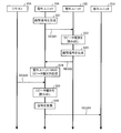
- 6 is a sequence diagram showing an example of a repeater identification process flow in the air-conditioning system according to Embodiment 1.
- FIG. 1 is a block diagram illustrating an example of a configuration of an air conditioning system according to Embodiment 1.
- FIG. It is a block diagram which shows an example of a structure of the communication control apparatus of FIG. It is the schematic which shows an example of the data structure of the signal which flows through
- FIG. 6 is a block diagram illustrating an example of a configuration of a communication control device in an outdoor unit according to Embodiment 2.
- FIG. FIG. 10 is a schematic diagram for explaining an operation of the communication control apparatus according to the second embodiment.
- FIG. 10 is a sequence diagram showing an example of a repeater identification process flow in the air-conditioning system according to Embodiment 2.
- Embodiment 1 FIG.
- the air conditioning system according to Embodiment 1 performs signal transmission / reception between a plurality of air conditioning apparatuses having different communication methods.
- FIG. 1 is a block diagram illustrating an example of the configuration of the air-conditioning system 100 according to the first embodiment.
- the air conditioning system 100 includes a plurality of air conditioning apparatuses 1 ⁇ / b> A and 1 ⁇ / b> B and a centralized management apparatus 2.
- the air conditioning system 100 is provided with two air conditioning apparatuses 1A and 1B, but is not limited thereto, and three or more air conditioning apparatuses may be provided. .
- the plurality of air conditioners 1A and 1B and the central control device 2 are connected by a dedicated transmission line 3.
- the transmission line 3 is a signal carrier medium for performing communication based on a communication protocol unique to the air conditioning system 100 between the air conditioning apparatuses 1A and 11B and the centralized management apparatus 2.
- the centralized management device 2 manages and controls the air conditioners 1A and 1B by transmitting and receiving various data to and from the air conditioners 1A and 1B via the transmission line 3. For example, the central management device 2 receives information indicating the states of the air conditioners 1A and 1B and transmits a control signal for controlling the air conditioners 1A and 1B via the transmission line 3.
- Air conditioning devices 1A and 1B receive a control signal including a control command transmitted from the central management device 2 via the transmission line 3, and perform an air conditioning operation based on the received control signal.
- the air conditioning apparatuses 1A and 1B transmit a signal including data necessary for the centralized management apparatus 2 to perform control to the centralized management apparatus 2 during operation.
- the air conditioner 1A includes an outdoor unit 10A, an indoor unit 20A, and a remote controller (hereinafter referred to as “remote controller”) 30A.
- the air conditioner 1A includes one outdoor unit 10A, two indoor units 20A, and one remote controller 30A.
- the outdoor unit 10A and the indoor unit 20A are connected by a refrigerant pipe 4A, thereby forming a refrigerant circuit.
- R32 or R410A is used as the refrigerant circulating in the refrigerant circuit.
- the air conditioner 1B includes an outdoor unit 10B, an indoor unit 20B, and a remote controller 30B.
- the air conditioner 1B includes one outdoor unit 10B, two indoor units 20B, and one remote controller 30B.
- the outdoor unit 10B and the indoor unit 20B are connected by a refrigerant pipe 4B, thereby forming a refrigerant circuit.
- the number of the outdoor units 10A and 10B, the indoor units 20A and 20B, and the remote controllers 30A and 30B is not limited to this example, and may be an arbitrary number.
- the air conditioners 1A and 1B are not the same configuration, and may have different configurations such that the number of devices is different.
- the outdoor unit 10A includes a communication control device 11A.
- the outdoor unit 10B includes a communication control device 11B.
- the communication control devices 11A and 11B are performed between the centralized management device 2 and the air conditioners 1A and 1B connected by the transmission line 3, and between each equipment in the air conditioners 1A and 1B. Control communication.
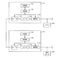
- FIG. 2 is a block diagram showing an example of the configuration of the communication control devices 11A and 11B in FIG.
- the communication control apparatus 11A includes a communication unit 111A, a repeater 112A, a switch 113A, a control unit 114A, and a storage unit 115A.
- the communication control device 11B includes a communication unit 111B, a repeater 112B, a switch 113B, a control unit 114B, and a storage unit 115B. Note that the communication control apparatuses 11A and 11B have the same configuration, and therefore, the communication control apparatus 11A will be described below as an example.
- the communication unit 111A is an interface for communicating with equipment such as the indoor unit 20A and the remote controller 30A provided in the air conditioner 1A via the transmission line 3.
- 111 A of communication parts transmit the received signal to a transmission destination based on control of 114 A of control parts.
- the repeater 112A relays the signal received via the transmission line 3. Specifically, the repeater 112A transmits a signal from the equipment received by the communication unit 111A via the transmission line 3 to the central management device 2 or another air conditioner 1B. Further, the repeater 112A transmits a signal received from the central management device 2 or another air conditioner 1B via the transmission line 3 to the equipment via the communication unit 111A.
- the repeater 112A has a function of correctly shaping the waveform of the received signal.
- the signal transmitted through the transmission line 3 may be disturbed due to noise superimposed during transmission.
- the repeater 112A removes noise superimposed on the signal and shapes it to a signal waveform equivalent to the signal waveform at the time of transmission. Thereby, a transmission error when a signal is transmitted to the transmission destination is suppressed.
- the repeater 112A has been described as being built in the communication control device 11A, but is not limited thereto, and may be provided outside the communication control device 11A, for example.
- the switch 113A is provided between the repeater 112A and the transmission line 3 connected to the central control device 2 and the other air conditioner 1B.
- the switch 113A shuts off and relays the signal by opening and closing the contact based on the control of the control unit 114A.
- Control unit 114A controls communication unit 111A and switch 113A to control communication in outdoor unit 10A.
- the control unit 114A interprets a communication command included in a signal received via the communication unit 111A, controls opening / closing of the switch 113A, and gives a communication command to the communication unit 111A.
- the control unit 114A is configured with various functions by executing software on an arithmetic device such as a microcomputer, or configured with hardware such as a circuit device that implements various functions.
- the storage unit 115A is composed of, for example, a non-volatile memory, and stores in advance a program for controlling the outdoor unit 10A.
- storage unit 115A stores in advance type information indicating the type of repeater 112A.
- the type information is information including the frequency of a signal that can be handled by the repeater 112A or 112B.
- the storage unit 115A stores various data based on the control of the control unit 114A.
- the remote controller 30A in FIG. 1 is used when operating the air conditioner 1A.
- the remote controller 30A transmits an operation signal corresponding to the operation by the user to the outdoor unit 10A and the indoor unit 20A via the transmission line 3.
- the remote controller 30A can operate not only the air conditioner 1A provided with the device itself but also other air conditioners 1B. That is, the remote controller 30A can also transmit an operation signal to the outdoor unit 10B and the indoor unit 20B.
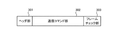
- FIG. 3 is a schematic diagram illustrating an example of a data structure of a signal flowing through the transmission line 3.
- the signal includes a header part 301, a communication command part 302, and a frame check part 303.
- the header section 301 stores address information for identifying equipment such as a transmission source address and a transmission destination address, and information indicating the message length of the information stored in the communication command section 302. As the transmission address at this time, an address corresponding to a specific facility device is designated, but other than this, an address corresponding to all the facility devices can also be designated.
- the communication command section 302 stores information related to communication commands. Specifically, for example, the communication command unit 302 stores a command for monitoring the state of the equipment and information for controlling the equipment.
- the frame check unit 303 stores a code for detecting a transmission error when a signal is transmitted and received.
- the communication command unit 302 stores the type information of the repeater 112A or 112B.
- signals transmitted and received between the air conditioner 1A and the air conditioner 1B are relayed using the repeaters 112A and 112B of the outdoor units 10A and 10B provided in the air conditioners 1A and 1B, respectively.
- the repeaters 112A and 112B can handle a first signal having a standard frequency which is at least a standard frequency in order to ensure upward compatibility.
- the repeaters 112A and 112B may have preset frequencies of signals that can be handled in addition to the first signal.
- the frequency of the corresponding signal in this case is the type of each of the repeaters 112A and 112B. It depends on.
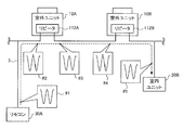
- FIG. 4 is a schematic diagram for explaining signal states of the respective parts when the first signal is transmitted and received between the air conditioner 1A and the air conditioner 1B.
- FIG. 4 shows an example in which an operation signal is transmitted from the remote controller 30A of the air conditioner 1A to the indoor unit 20B of the air conditioner 1B using the first signal.
- the first signal is a standard frequency signal and can be handled by both the air conditioner 1A and the air conditioner 1B.
- an operation signal is transmitted from the remote controller 30A using the first signal, and the transmitted operation signal is relayed by the outdoor units 10A and 10B and received by the indoor unit 20B.
- signal waveform # 1 shows a state immediately after being transmitted from remote controller 30A.
- Signal waveform # 2 shows a state immediately before being received by the repeater 112A of the outdoor unit 10A.
- the waveform of the signal waveform # 2 is disturbed compared to the signal waveform # 1 due to noise superimposed when passing through the transmission line 3.
- the signal waveform # 3 shows a state immediately after being relayed and transmitted by the repeater 112A.
- the signal waveform # 3 has a waveform equivalent to the signal waveform # 1 by removing noise by the repeater 112A and shaping the waveform.
- Signal waveform # 4 shows a state immediately before being received by the repeater 112B of the outdoor unit 10B.
- the waveform of the signal waveform # 4 is disturbed compared to the signal waveform # 3 due to noise superimposed when passing through the transmission line 3.
- the signal waveform # 5 indicates a state immediately before being transmitted by being relayed by the repeater 112B and received by the indoor unit 20B.
- the signal waveform # 5 has a waveform equivalent to the signal waveform # 3 by removing noise by the repeater 112B and shaping the waveform.
- the repeaters 112A and 112B are normally relayed as the first signal. Therefore, the operation signal transmitted from the remote controller 30A can be normally received by the indoor unit 20B while removing noise superimposed when transmitted via the transmission line 3.
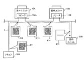
- FIG. 5 is a schematic diagram for explaining the signal states of the respective parts when the second signal is transmitted and received between the air conditioner 1A and the air conditioner 1B.
- FIG. 5 shows an example in which an operation signal is transmitted from the remote controller 30A of the air conditioner 1A to the indoor unit 20B of the air conditioner 1B, as in the example of FIG. However, the operation signal at this time is transmitted from the remote controller 30A using a second signal different from the first signal.
- the second signal is a signal having a frequency different from the frequency of the first signal, and has a higher frequency than the first signal, for example.
- the second signal is a signal having a frequency twice that of the first signal. Thereby, the data transfer amount per unit time of the second signal is doubled as compared with the first signal.
- the second signal can be handled only by the air conditioner 1A. That is, the repeater 112A of the air conditioner 1A can relay the second signal, but the repeater 112B of the air conditioner 1B cannot relay the second signal.
- an operation signal is transmitted from the remote controller 30A using the second signal, and the transmitted operation signal is relayed by the outdoor units 10A and 10B and received by the indoor unit 20B.
- signal waveform # 11 indicates a state immediately after being transmitted from remote controller 30A.
- Signal waveform # 12 shows a state immediately before being received by the repeater 112A of the outdoor unit 10A.
- the waveform of the signal waveform # 2 is disturbed compared to the signal waveform # 11 due to noise superimposed when passing through the transmission line 3.
- Signal waveform # 13 shows a state immediately after being relayed and transmitted by repeater 112A.
- the signal waveform # 13 has a waveform equivalent to the signal waveform # 11 by removing noise by the repeater 112A and shaping the waveform.
- Signal waveform # 14 shows a state immediately before being received by the repeater 112B of the outdoor unit 10B.
- the waveform of the signal waveform # 14 is disturbed compared to the signal waveform # 13 due to noise superimposed when passing through the transmission line 3.
- Signal waveform # 15 indicates a state immediately before being transmitted by being relayed by the repeater 112B and received by the indoor unit 20B. At this time, the repeater 112B does not correspond to the frequency of the second signal. Therefore, repeater 112B determines that all the frequency components of the received signal indicated by signal waveform # 14 are noise and relays them. As a result, the signal waveform # 15 has all frequency components removed.
- the second signal when used as a signal transmitted and received between the air conditioner 1A and the air conditioner 1B, the second signal is not normally relayed by the repeater 112B. For this reason, the operation signal transmitted from the remote controller 30A cannot be normally received by the indoor unit 20B.
- FIG. 6 is a sequence diagram showing an example of a repeater identification process in the air-conditioning system 100 according to Embodiment 1.
- FIG. 6 shows an example in which signals are transmitted and received between the remote controller 30A of the air conditioner 1A and the indoor unit 20B of the air conditioner 1B.
- step S1 the remote controller 30A generates an identification signal for identifying the repeater 112A of the outdoor unit 10A at the time of activation.
- all addresses are set as the transmission destination addresses in the header portion 301 of the identification signal.
- the communication command unit 302 stores request information for requesting the type of the repeater 112A.
- the identification signal generated in step S1 is transmitted from the remote controller 30A to the outdoor unit 10A.
- the identification signal is transmitted using a first signal that can be relayed by the repeater regardless of the type of the repeater.
- the identification signal transmitted from the remote controller 30A is received by the control unit 114A via the communication unit 111A of the outdoor unit 10A.
- step S2 the control unit 114A receives the identification signal, and when recognizing that the request information is stored in the communication command unit 302 of the identification signal, the control unit 114A controls the switch 113A so that the switch 113A is opened. . Thereby, communication is interrupted
- control unit 114A reads the type information of repeater 112A stored in storage unit 115A based on the request information stored in communication command unit 302 of the identification signal.
- step S4 the control unit 114A generates a response signal in which the read type information is stored in the communication command unit 302.
- the address of the remote controller 30A is set as the transmission destination address.
- sequence SEQ2 the response signal generated in step S4 is transmitted to remote controller 30A via communication unit 111A.
- step S5 the control unit 114A controls the switch 113A so that the switch 113A is closed after transmitting the response signal and completing the response.
- step S6 when receiving the response signal, the remote controller 30A stores the type information of the repeater 112A of the outdoor unit 10A stored in the communication command unit 302 of the received response signal in a nonvolatile memory (not shown).
- step S7 the indoor unit 20B generates an identification signal for identifying the repeater 112B of the outdoor unit 10B at the time of activation.
- all addresses are set as the transmission destination addresses in the header portion 301 of the identification signal.
- the communication command section 302 stores request information for requesting the type of the repeater 112B.
- the identification signal generated in step S7 is transmitted from the indoor unit 20B to the outdoor unit 10B.
- the identification signal is transmitted using the first signal.
- the identification signal transmitted from the indoor unit 20B is received by the control unit 114B via the communication unit 111B of the outdoor unit 10B.
- step S8 when the control unit 114B receives the identification signal and recognizes that the request information is stored in the communication command unit 302 of the identification signal, the control unit 114B controls the switch 113B so that the switch 113B is opened. . Thereby, communication is interrupted
- step S9 the control unit 114B reads the type information of the repeater 112B stored in the storage unit 115B based on the request information stored in the communication command unit 302 of the identification signal.
- step S10 the control unit 114B generates a response signal in which the read type information is stored in the communication command unit 302.
- the address of the indoor unit 20B is set as the transmission destination address.
- sequence SEQ4 the response signal generated in step S10 is transmitted to the indoor unit 20B via the communication unit 111B.
- step S11 after transmitting the response signal and completing the response, the control unit 114B controls the switch 113B so that the switch 113B is closed.
- step S12 when the indoor unit 20B receives the response signal, the indoor unit 20B stores the type information of the repeater 112B of the outdoor unit 10B stored in the communication command unit 302 of the received response signal in a nonvolatile memory (not shown).
- step S13 the control unit 114A of the remote controller 30A generates a type signal in which the type information of the repeater 112A stored in step S6 is stored in the communication command unit 302.
- the address of the indoor unit 20B is set as the transmission destination address.
- step S14 the control unit 114B of the indoor unit 20B generates a type signal in which the type information of the repeater 112B stored in step S12 is stored in the communication command unit 302.
- the address of the remote controller 30A is set as the transmission destination address.
- step SEQ5 the type signal generated in step S13 is transmitted to the indoor unit 20B via the outdoor units 10A and 10B.
- the type signal is transmitted using the first signal.
- step S15 when receiving the type signal, the indoor unit 20B stores the type information of the repeater 112A of the outdoor unit 10A stored in the communication command unit 302 of the type signal in the nonvolatile memory.
- step SEQ6 the type signal generated in step S14 is transmitted to the remote controller 30A via the outdoor units 10B and 10A.
- the type signal is transmitted using the first signal.
- step S16 when receiving the type signal, the remote controller 30A stores the type information of the repeater 112A of the outdoor unit 10A stored in the communication command unit 302 of the type signal in the nonvolatile memory.
- the remote controller 30A and the indoor unit 20B can recognize the type of repeater existing on the transmission line 3 when transmitting and receiving signals to and from each other. Thereafter, when signals are transmitted / received between the remote controller 30A and the indoor unit 20B, the signals are transmitted / received using a signal having an optimum frequency among the frequencies corresponding to the repeaters on the transmission line 3.
- the remote controller 30A and the indoor unit 20B transmit and receive using the first signal. I do. Further, when the repeaters 112A and 112B existing on the transmission line 3 between the remote controller 30A and the indoor unit 20B correspond to the frequency of the second signal, the remote controller 30A and the indoor unit 20B perform transmission / reception using the second signal. Do.
- the remote control 30A and the indoor unit 20B have the same frequency. Communication is performed using the signal. As a result, communication can be normally performed even when devices having different frequencies, that is, different communication methods are mixed in the system.
- the remote controller 30A acquires the type information of the repeater 112A from the outdoor unit 10A, and the indoor unit 20B acquires the type information of the repeater 112B from the outdoor unit 10B. Thereby, since the frequency of the signal to be transmitted / received is determined based on the acquired type information, communication can be performed without exchanging the repeater.
- the remote controller 30A transmits the type information of the repeater 112A to the indoor unit 20B as a standard frequency signal
- the indoor unit 20B transmits the type information of the repeater 112B to the remote control 30A as a standard frequency signal.
- the remote controller 30A and the indoor unit 20B can grasp the type of repeater of the communication partner.
- control unit 114A opens the switch 113A when receiving an identification signal for requesting the type information of the repeater 112A from the remote controller 30A. Thereby, communication is interrupted
- control unit 114B opens the switch 113B when receiving an identification signal for requesting the type information of the repeater 112B from the indoor unit 20B. Thereby, communication is interrupted
- the set frequency is set to a frequency higher than the standard frequency. Therefore, the data transfer amount per unit time when the set frequency is used can be increased as compared with the case where the standard frequency is used.
- Embodiment 2 a second embodiment of the present invention will be described.
- the configuration of the communication control device provided in the outdoor unit is different from that in the first embodiment.
- the same reference numerals are given to portions common to the first embodiment, and detailed description is omitted.
- FIG. 7 is a block diagram illustrating an example of the configuration of the communication control device 120A in the outdoor unit 10A according to the second embodiment and the communication control device 11B in the outdoor unit 10B.
- the communication control device 120A includes communication units 121A and 122A, a control unit 123A, and a storage unit 124A.
- the communication control device 11B includes a communication unit 111B, a repeater 112B, a switch 113B, a control unit 114B, and a storage unit 115B.
- the communication unit 121A is an interface for communicating with equipment such as the indoor unit 20A and the remote controller 30A provided in the air conditioner 1A via the transmission line 3.
- the communication unit 121A supplies the signal received from the equipment to the control unit 123A.
- the communication unit 121A transmits the signal supplied from the control unit 123A to the equipment.
- the communication unit 122A is an interface for communicating with the centralized management device 2 or the air conditioning device 1B via the transmission line 3.
- 122 A of communication parts supply the signal received from the centralized management apparatus 2 or the air conditioning apparatus 1B to 123 A of control parts.
- the communication unit 122A transmits the signal supplied from the control unit 123A to the central management device 2 or the air conditioning device 1B.
- the communication units 121A and 122A convert the frequency of the received signal into an arbitrary frequency based on the control of the control unit 123A.
- Control unit 123A controls communication units 121A and 122A to control communication in outdoor unit 10A.
- the control unit 123A controls the communication unit 122A so that the signal received by the communication unit 121A is supplied to the communication unit 122A, and the frequency of the signal is converted and transmitted as necessary.
- the control unit 123A controls the communication unit 121A so that the signal received by the communication unit 122A is supplied to the communication unit 121A, and the frequency of the signal is converted and transmitted as necessary.
- the control unit 123A is configured with various functions by executing software on an arithmetic device such as a microcomputer, or configured with hardware such as a circuit device that implements various functions.
- the storage unit 124A is composed of, for example, a non-volatile memory, and stores in advance a program for controlling the outdoor unit 10A.
- the storage unit 124A writes and reads various stored information based on the control of the control unit 123A.
- the storage unit 124A stores type information indicating the type of the repeater 112B supplied during transmission processing based on the control of the control unit 123A.
- the air conditioning system 100 transmits and receives signals via the transmission line 3 between the air conditioner 1A and the air conditioner 1B, as in the first embodiment.
- FIG. 8 is a schematic diagram for explaining the operation of the communication control apparatus 120A according to the second embodiment.
- FIG. 8 shows an example in which a signal received via the communication unit 122A is transmitted via the communication unit 121A.
- the received signal is transmitted to the control unit 123A via the communication unit 122A.
- the control unit 123A supplies the signal to the communication unit 121A.
- the control unit 123A controls the communication unit 121A so as to convert the frequency of the signal in consideration of the frequency corresponding to the repeater of the transmission destination device.
- the communication unit 121A converts the frequency of the signal supplied from the control unit 123A.
- the communication unit 121A transmits a signal whose frequency has been converted to the transmission destination.
- a low frequency signal is converted into a high frequency signal.
- a high frequency signal may be converted into a low frequency signal.
- the control unit 123A needs to convert the frequency of the signal to a frequency corresponding to the repeater of the transmission destination device. Therefore, in the second embodiment, repeater identification processing is performed in order to recognize the frequency corresponding to the repeater of the transmission destination apparatus.
- FIG. 9 is a sequence diagram illustrating an example of the flow of repeater identification processing in the air-conditioning system 100 according to Embodiment 2.
- FIG. 9 shows an example in which signals are transmitted and received between the remote controller 30A of the air conditioner 1A and the indoor unit 20B of the air conditioner 1B.
- step S21 the outdoor unit 10A of the air conditioner 1A generates an identification signal for identifying the repeater 112B of the outdoor unit 10B by the control unit 123A at the time of activation.
- the address of the outdoor unit 10B is set as the transmission destination address.
- the communication command section 302 stores request information for requesting the type of the repeater 112B.
- the identification signal generated in step S21 is transmitted from the outdoor unit 10A to the outdoor unit 10B.
- the identification signal may be a signal of any frequency as long as the frequency corresponds to the communication unit 122A of the outdoor unit 10A.
- step S22 the control unit 114B receives the identification signal via the communication unit 122A and, based on the request information stored in the communication command unit 302 of the received identification signal, the repeater 112B stored in the storage unit 115B. Read type information.
- step S23 the control unit 114B generates a response signal in which the read type information is stored in the communication command unit 302. In the header portion 301 of the response signal, the address of the outdoor unit 10A is set as the transmission destination address.
- step SEQ22 the response signal generated in step S23 is transmitted to the control unit 123A via the communication unit 122A of the outdoor unit 10A.
- step S24 when receiving the response signal, the control unit 123A stores the type information of the repeater 112B of the outdoor unit 10B stored in the communication command unit 302 of the received response signal in the storage unit 124A.
- a signal to be transmitted such as an operation signal is transmitted from the remote control 30A to the indoor unit 20B in sequence SEQ23. .
- the address of the indoor unit 20B is set as the transmission destination address.
- the signal transmitted at this time may be a signal having any frequency as long as the frequency corresponds to the communication unit 122A of the outdoor unit 10A.
- step S25 the control unit 123A of the outdoor unit 10A receives the signal transmitted from the remote controller 30A via the communication unit 121A.
- the control unit 123A determines that the transmission destination address set in the header portion 301 of the signal indicates the indoor unit 20B, and stores the type information of the repeater 112B of the outdoor unit 10B stored in the storage unit 124A. read out.
- step S26 the control unit 123A controls the communication unit 122A so as to convert the frequency of the received signal into a frequency corresponding to the repeater 112B based on the read type information of the repeater 112B. Thereby, 122 A of communication parts convert the frequency of a signal.
- sequence SEQ24 the signal converted in step S26 is transmitted to the indoor unit 20B via the outdoor unit 10B.
- the outdoor unit 10A can recognize the type of repeater existing on the transmission line 3 when transmitting and receiving signals. Thereafter, when signals are transmitted / received between the remote controller 30A and the indoor unit 20B, the signals are transmitted / received using a signal having an optimum frequency among the frequencies corresponding to the repeaters on the transmission line 3.
- the remote controller 30A and the indoor unit 20B perform transmission / reception using the first signal.
- the repeater 112B existing on the transmission line 3 between the remote controller 30A and the indoor unit 20B corresponds to the frequency of the second signal
- the remote controller 30A and the indoor unit 20B perform transmission / reception using the second signal.
- the communication unit 122A of the outdoor unit 10A converts the frequency of the signal received from the remote controller 30A into a frequency corresponding to the repeater 112B, and is converted.
- a signal is transmitted to the indoor unit 20B.
- the outdoor unit 10A acquires the type information of the repeater 112B stored in the storage unit 115B. Thereby, since outdoor unit 10A can grasp
- the frequency of the received signal is set to the set frequency included in the acquired type information of the repeater 112B. Convert to As a result, as in the first embodiment, communication can be normally performed even when devices having different communication methods are mixed in the system.
- the set frequency is set higher than the frequency of the signal received from the remote control 30A.
- the data transfer amount per unit time can be increased.
Landscapes
- Engineering & Computer Science (AREA)
- Chemical & Material Sciences (AREA)
- Combustion & Propulsion (AREA)
- Mechanical Engineering (AREA)
- General Engineering & Computer Science (AREA)
- Human Computer Interaction (AREA)
- Air Conditioning Control Device (AREA)
Abstract
室外ユニット、室内ユニットおよびリモートコントローラをそれぞれ備える複数の空気調和装置が伝送線で接続された空気調和システムであって、それぞれの室外ユニットは、信号の送受信を行う通信部と、設定周波数の信号を中継するリピータとを有し、一方のリピータが対応する設定周波数と、他方のリピータが対応する設定周波数とが一致する場合に、一方のリモートコントローラおよび他方の室内ユニットが一致した設定周波数の信号を用いて通信を行う。
Description
本発明は、複数の空気調和装置の間で通信を行う空気調和システムに関するものである。
従来、室外ユニットおよび室内ユニット等の複数の設備機器で構成された空気調和システムでは、設備機器同士が伝送線によって接続されている(例えば、特許文献1参照)。特許文献1に記載の空気調和システムでは、複数の空気調和装置それぞれの室外ユニット同士が通信用の伝送線で接続され、伝送線を介して互いに通信を行う。これにより、空気調和装置同士が連動して空気調和を行う。
空気調和装置同士が伝送線で接続されて通信が行われる場合、伝送線によって形成される通信経路上には、一般に、伝送距離の延長、およびノイズが重畳した信号を整形することを目的として、リピータが設置される。
ところで、従来の空気調和システムにおいて、一部の空気調和装置を置き換えた場合などには、異なる通信方式を採用している空気調和装置同士が伝送線を介して通信を行う場合がある。この場合の通信は、通常、上位互換が確保され、上位の通信方式で下位の通信方式を扱うことができるように設計されている。すなわち、互いの装置が上位の通信方式に対応している場合は、上位の通信方式を用いて通信が行われる。一方、いずれかの装置が上位の通信方式に対応していない場合は、標準の通信方式である下位の通信方式を用いて通信が行われる。
しかしながら、この場合には、それぞれの空気調和装置で採用されている通信方式が混在するため、どの通信方式を用いて通信を行うと最適な通信を行うことができるのかが判断できない。そのため、空気調和装置間で確実に通信を行うには、標準の通信方式を用いる必要があり、通信速度等を向上させることができない。
本発明は、上記の課題に鑑みてなされたものであって、通信方式の異なる装置が混在していた場合でも、通信を正常に行うことができる空気調和システムを提供することを目的とする。
本発明の空気調和システムは、室外ユニット、室内ユニットおよびリモートコントローラをそれぞれ備える複数の空気調和装置が伝送線で接続された空気調和システムであって、それぞれの前記室外ユニットは、信号の送受信を行う通信部と、設定周波数の信号を中継するリピータとを有し、一方の前記リピータが対応する設定周波数と、他方の前記リピータが対応する設定周波数とが一致する場合に、一方の前記リモートコントローラおよび他方の前記室内ユニットが一致した前記設定周波数の信号を用いて通信を行うものである。
本発明によれば、一方のリピータが対応する設定周波数と、他方のリピータが対応する設定周波数とが一致する場合に、一致した設定周波数の信号を用いて通信を行うことにより、通信方式の異なる装置が混在していた場合でも、通信を正常に行うことができる。
実施の形態1.
以下、本発明の実施の形態1に係る空気調和システムについて説明する。本実施の形態1に係る空気調和システムは、通信方式の異なる複数の空気調和装置間で信号の送受信を行うものである。
以下、本発明の実施の形態1に係る空気調和システムについて説明する。本実施の形態1に係る空気調和システムは、通信方式の異なる複数の空気調和装置間で信号の送受信を行うものである。
[空気調和システム100の構成]
図1は、本実施の形態1に係る空気調和システム100の構成の一例を示すブロック図である。図1に示すように、空気調和システム100は、複数の空気調和装置1Aおよび1Bと、集中管理装置2とで構成されている。なお、図1に示す例において、空気調和システム100には、2台の空気調和装置1Aおよび1Bが設けられているが、これに限られず、3台以上の空気調和装置が設けられてもよい。
図1は、本実施の形態1に係る空気調和システム100の構成の一例を示すブロック図である。図1に示すように、空気調和システム100は、複数の空気調和装置1Aおよび1Bと、集中管理装置2とで構成されている。なお、図1に示す例において、空気調和システム100には、2台の空気調和装置1Aおよび1Bが設けられているが、これに限られず、3台以上の空気調和装置が設けられてもよい。
複数の空気調和装置1Aおよび1Bと集中管理装置2とは、専用の伝送線3によって接続されている。伝送線3は、空気調和装置1Aおよび11Bと集中管理装置2との間で、空気調和システム100独自の通信プロトコルに準拠した通信を行うための信号搬送媒体である。
(集中管理装置2)
集中管理装置2は、伝送線3を介して空気調和装置1Aおよび1Bと各種のデータを送受信することにより、空気調和装置1Aおよび1Bの管理および制御を行う。例えば、集中管理装置2は、空気調和装置1Aおよび1Bの状態を示す情報を受信するとともに、伝送線3を介して空気調和装置1Aおよび1Bを制御するための制御信号を送信する。
集中管理装置2は、伝送線3を介して空気調和装置1Aおよび1Bと各種のデータを送受信することにより、空気調和装置1Aおよび1Bの管理および制御を行う。例えば、集中管理装置2は、空気調和装置1Aおよび1Bの状態を示す情報を受信するとともに、伝送線3を介して空気調和装置1Aおよび1Bを制御するための制御信号を送信する。
(空気調和装置1Aおよび1B)
空気調和装置1Aおよび1Bは、集中管理装置2から送信された制御指令等を含む制御信号を、伝送線3を介して受信し、受信した制御信号に基づき、空調運転を行う。また、空気調和装置1Aおよび1Bは、運転の際に、集中管理装置2が制御を行うために必要となるデータを含む信号を、集中管理装置2に送信する。
空気調和装置1Aおよび1Bは、集中管理装置2から送信された制御指令等を含む制御信号を、伝送線3を介して受信し、受信した制御信号に基づき、空調運転を行う。また、空気調和装置1Aおよび1Bは、運転の際に、集中管理装置2が制御を行うために必要となるデータを含む信号を、集中管理装置2に送信する。
空気調和装置1Aは、室外ユニット10A、室内ユニット20Aおよびリモートコントローラ(以下、「リモコン」と称する)30Aを備えている。図1に示す例において、空気調和装置1Aは、1台の室外ユニット10Aと、2台の室内ユニット20Aと、1台のリモコン30Aとを備えている。室外ユニット10Aと室内ユニット20Aとは、冷媒配管4Aで接続され、これによって冷媒回路が形成される。冷媒回路を循環する冷媒として、例えばR32またはR410A等が用いられる。
空気調和装置1Bは、室外ユニット10B、室内ユニット20Bおよびリモコン30Bを備えている。図1に示す例において、空気調和装置1Bは、1台の室外ユニット10Bと、2台の室内ユニット20Bと、1台のリモコン30Bとを備えている。室外ユニット10Bと室内ユニット20Bとは、冷媒配管4Bで接続され、これによって冷媒回路が形成される。
なお、空気調和装置1Aおよび1Bのそれぞれにおいて、室外ユニット10Aおよび10B、室内ユニット20Aおよび20B、ならびにリモコン30Aおよび30Bの台数は、この例に限られず、任意の台数であってもよい。また、空気調和装置1Aおよび1Bは、同一の構成ではなく、各機器の台数が異なるような、それぞれが異なる構成であってもよい。
(室外ユニット10Aおよび10B)
室外ユニット10Aは、通信制御装置11Aを備えている。室外ユニット10Bは、通信制御装置11Bを備えている。通信制御装置11Aおよび11Bは、伝送線3で接続された集中管理装置2、空気調和装置1Aおよび1Bの間で行われる通信、ならびに、空気調和装置1Aおよび1B内の各設備機器間で行われる通信を制御する。
室外ユニット10Aは、通信制御装置11Aを備えている。室外ユニット10Bは、通信制御装置11Bを備えている。通信制御装置11Aおよび11Bは、伝送線3で接続された集中管理装置2、空気調和装置1Aおよび1Bの間で行われる通信、ならびに、空気調和装置1Aおよび1B内の各設備機器間で行われる通信を制御する。
図2は、図1の通信制御装置11Aおよび11Bの構成の一例を示すブロック図である。図2に示すように、通信制御装置11Aは、通信部111A、リピータ112A、スイッチ113A、制御部114Aおよび記憶部115Aを備えている。また、通信制御装置11Bは、通信部111B、リピータ112B、スイッチ113B、制御部114Bおよび記憶部115Bを備えている。なお、通信制御装置11Aおよび11Bは、同様の構成を有するため、以下では、通信制御装置11Aを例にとって説明する。
通信部111Aは、伝送線3を介して空気調和装置1Aに設けられた室内ユニット20Aおよびリモコン30A等の設備機器と通信を行うためのインタフェースである。通信部111Aは、制御部114Aの制御に基づき、受信した信号を送信先に送信する。
リピータ112Aは、伝送線3を介して受信した信号を中継する。具体的には、リピータ112Aは、伝送線3を介して通信部111Aで受信した設備機器からの信号を、集中管理装置2または他の空気調和装置1Bに送信する。また、リピータ112Aは、伝送線3を介して集中管理装置2または他の空気調和装置1Bから受信した信号を、通信部111Aを介して設備機器に送信する。
さらに、リピータ112Aは、受信した信号の波形を正しく整形する機能を有している。伝送線3によって伝送される信号は、伝送中にノイズが重畳して波形が乱れることがある。このような場合に、リピータ112Aは、信号に重畳するノイズを除去し、送信時の信号波形と同等の信号波形に整形する。これにより、信号が送信先に伝送された際の伝送エラーが抑制される。
なお、リピータ112Aは、通信制御装置11Aに内蔵されるように説明したが、これに限られず、例えば通信制御装置11Aの外部に設けられてもよい。
スイッチ113Aは、リピータ112Aと集中管理装置2および他の空気調和装置1Bに接続されている伝送線3との間に設けられている。スイッチ113Aは、制御部114Aの制御に基づいて接点が開閉されることにより、信号の遮断および中継を行う。
制御部114Aは、通信部111Aおよびスイッチ113Aを制御して、室外ユニット10Aにおける通信を制御する。例えば、制御部114Aは、通信部111Aを介して受信した信号に含まれる通信コマンドを解釈し、スイッチ113Aの開閉を制御するとともに、通信部111Aに対して通信指令を与える。制御部114Aは、マイクロコンピュータなどの演算装置上でソフトウェアを実行することにより各種機能が実現され、もしくは各種機能を実現する回路デバイスなどのハードウェア等で構成されている。
記憶部115Aは、例えば不揮発性メモリで構成され、室外ユニット10Aを制御するためのプログラム等を予め記憶している。また、本実施の形態1において、記憶部115Aは、リピータ112Aの種別を示す種別情報を予め記憶している。種別情報は、リピータ112Aまたは112Bが扱うことのできる信号の周波数を含む情報である。また、記憶部115Aは、制御部114Aの制御に基づき、各種データが記憶される。
(リモコン30A)
図1のリモコン30Aは、空気調和装置1Aを操作する際に用いられる。リモコン30Aは、ユーザによる操作に応じた操作信号を、伝送線3を介して室外ユニット10Aおよび室内ユニット20Aに送信する。
図1のリモコン30Aは、空気調和装置1Aを操作する際に用いられる。リモコン30Aは、ユーザによる操作に応じた操作信号を、伝送線3を介して室外ユニット10Aおよび室内ユニット20Aに送信する。
また、本実施の形態1において、リモコン30Aは、自装置が設けられた空気調和装置1Aだけでなく、他の空気調和装置1Bを操作することもできる。すなわち、リモコン30Aは、操作信号を室外ユニット10Bおよび室内ユニット20Bに送信することもできる。
[信号のデータ構造]
各設備機器間で伝送線3を介して送受信される信号のデータ構造について説明する。図3は、伝送線3を流れる信号のデータ構造の一例を示す概略図である。図3に示すように、信号は、ヘッダ部301、通信コマンド部302およびフレームチェック部303で構成されている。
各設備機器間で伝送線3を介して送受信される信号のデータ構造について説明する。図3は、伝送線3を流れる信号のデータ構造の一例を示す概略図である。図3に示すように、信号は、ヘッダ部301、通信コマンド部302およびフレームチェック部303で構成されている。
ヘッダ部301には、送信元アドレスおよび送信先アドレス等の設備機器を識別するためのアドレス情報と、通信コマンド部302に格納された情報の電文長を示す情報とが格納されている。このときの送信アドレスは、特定の設備機器に対応するものが指定されるが、これ以外に、すべての設備機器に対応するものが指定されることもできる。
通信コマンド部302には、通信コマンドに関する情報が格納されている。具体的には、例えば、通信コマンド部302には、設備機器の状態を監視するための指令、および設備機器を制御するための情報が格納される。フレームチェック部303には、信号を送受信した際の伝送エラーを検出するためのコード等が格納されている。また、本実施の形態1において、通信コマンド部302には、リピータ112Aまたは112Bの種別情報が格納される。
[空気調和システム100の動作]
空気調和システム100の動作について説明する。本実施の形態1では、一方の空気調和装置1Aまたは1Bに設けられたリモコン30Aまたは30Bを用いて、他方の空気調和装置1Bまたは1Aの室外ユニット10Bまたは10A、ならびに室内ユニット20Bまたは20Aを操作することができる。すなわち、本実施の形態1では、空気調和装置1Aと空気調和装置1Bとの間で、伝送線3を介して信号の送受信を行うことができる。
空気調和システム100の動作について説明する。本実施の形態1では、一方の空気調和装置1Aまたは1Bに設けられたリモコン30Aまたは30Bを用いて、他方の空気調和装置1Bまたは1Aの室外ユニット10Bまたは10A、ならびに室内ユニット20Bまたは20Aを操作することができる。すなわち、本実施の形態1では、空気調和装置1Aと空気調和装置1Bとの間で、伝送線3を介して信号の送受信を行うことができる。
この場合、空気調和装置1Aと空気調和装置1Bとの間で送受信が行われる信号は、それぞれの空気調和装置1Aおよび1Bに設けられた室外ユニット10Aおよび10Bのリピータ112Aおよび112Bを用いて中継される。
リピータ112Aおよび112Bは、上位互換性を確保するため、少なくとも標準的な周波数である標準周波数の第1の信号を扱うことができる。一方で、リピータ112Aおよび112Bは、第1の信号以外にも扱うことができる信号の周波数が予め設定されている場合があり、この場合の対応する信号の周波数は、リピータ112Aおよび112Bそれぞれの種別によって異なる。
以下では、空気調和装置1Aおよび1Bに共通して対応する周波数の第1の信号を用いた場合と、空気調和装置1Aおよび1Bのいずれか一方にのみ対応する周波数の第2の信号を用いた場合とにおける、伝送時の信号の状態について説明する。
図4は、空気調和装置1Aと空気調和装置1Bとの間で第1の信号を送受信した場合の各部の信号状態について説明するための概略図である。図4は、空気調和装置1Aのリモコン30Aから空気調和装置1Bの室内ユニット20Bに対して第1の信号を用いて操作信号を送信する場合の例である。第1の信号は、標準周波数の信号であり、空気調和装置1Aおよび空気調和装置1Bの両方で扱うことができるものとする。
この例では、リモコン30Aから第1の信号を用いて操作信号が送信され、送信された操作信号は、室外ユニット10Aおよび10Bによって中継されて室内ユニット20Bで受信される。図4に示すように、信号波形#1は、リモコン30Aから送信された直後の状態を示す。
信号波形#2は、室外ユニット10Aのリピータ112Aで受信される直前の状態を示す。信号波形#2は、伝送線3を通過する際に重畳されたノイズにより、信号波形#1と比較して波形が乱れている。信号波形#3は、リピータ112Aで中継されて送信された直後の状態を示す。信号波形#3は、リピータ112Aによってノイズが除去され、波形が整形されることによって信号波形#1と同等の波形となっている。
信号波形#4は、室外ユニット10Bのリピータ112Bで受信される直前の状態を示す。信号波形#4は、伝送線3を通過する際に重畳されたノイズにより、信号波形#3と比較して波形が乱れている。信号波形#5は、リピータ112Bで中継されて送信され、室内ユニット20Bで受信される直前の状態を示す。信号波形#5は、リピータ112Bによってノイズが除去され、波形が整形されることによって信号波形#3と同等の波形となっている。
このように、空気調和装置1Aと空気調和装置1Bとの間で送受信される信号として第1の信号を用いた場合、第1の信号は、リピータ112Aおよび112Bが正常に中継される。そのため、リモコン30Aから送信された操作信号は、伝送線3を介して伝送される際に重畳されるノイズが除去されながら、室内ユニット20Bで正常に受信することができる。
図5は、空気調和装置1Aと空気調和装置1Bとの間で第2の信号を送受信した場合の各部の信号状態について説明するための概略図である。図5は、図4の例と同様に、空気調和装置1Aのリモコン30Aから空気調和装置1Bの室内ユニット20Bに対して操作信号を送信する場合の例である。ただし、このときの操作信号は、第1の信号とは異なる第2の信号を用いてリモコン30Aから送信される。
第2の信号は、第1の信号の周波数と異なる周波数を有する信号であり、例えば、第1の信号よりも高い周波数を有している。具体的には、図5の例において、第2の信号は、第1の信号の2倍の周波数を有する信号である。これにより、第2の信号は、第1の信号と比較して単位時間当たりのデータ転送量が2倍となる。
また、第2の信号は、空気調和装置1Aのみで扱うことができるものとする。すなわち、空気調和装置1Aのリピータ112Aは、第2の信号を中継することができるが、空気調和装置1Bのリピータ112Bは、第2の信号を中継することができない。
図5の例では、リモコン30Aから第2の信号を用いて操作信号が送信され、送信された操作信号は、室外ユニット10Aおよび10Bによって中継されて室内ユニット20Bで受信される。図5に示すように、信号波形#11は、リモコン30Aから送信された直後の状態を示す。
信号波形#12は、室外ユニット10Aのリピータ112Aで受信される直前の状態を示す。信号波形#2は、伝送線3を通過する際に重畳されたノイズにより、信号波形#11と比較して波形が乱れている。信号波形#13は、リピータ112Aで中継されて送信された直後の状態を示す。信号波形#13は、リピータ112Aによってノイズが除去され、波形が整形されることによって信号波形#11と同等の波形となっている。信号波形#14は、室外ユニット10Bのリピータ112Bで受信される直前の状態を示す。信号波形#14は、伝送線3を通過する際に重畳されたノイズにより、信号波形#13と比較して波形が乱れている。
信号波形#15は、リピータ112Bで中継されて送信され、室内ユニット20Bで受信される直前の状態を示す。このとき、リピータ112Bは、第2の信号の周波数に対応していない。そのため、リピータ112Bは、信号波形#14で示す受信信号のすべての周波数成分がノイズであると判断して中継する。これにより、信号波形#15は、すべての周波数成分が除去されたものとなる。
このように、空気調和装置1Aと空気調和装置1Bとの間で送受信される信号として第2の信号を用いた場合、第2の信号は、リピータ112Bで正常に中継されない。そのため、リモコン30Aから送信された操作信号は、室内ユニット20Bで正常に受信することができない。
伝送線3上に存在するリピータ112Aおよび112Bの種別が異なり、対応する信号の周波数が異なる場合、信号の周波数によっては、空気調和装置1Aと空気調和装置1Bとの間で信号の送受信を正常に行うことができない。そのため、このような場合には、それぞれの空気調和装置1Aおよび1Bに共通する周波数を用いて、信号を送信先へ送信する必要がある。
そこで、本実施の形態1では、空気調和装置1Aと空気調和装置1Bとの間で信号を送受信する際に、伝送線3上に存在するリピータ112Aおよび112Bの種別を識別するリピータ識別処理を行う。
(リピータ識別処理)
図6は、本実施の形態1に係る空気調和システム100におけるリピータ識別処理の流れの一例を示すシーケンス図である。なお、図6は、空気調和装置1Aのリモコン30Aと空気調和装置1Bの室内ユニット20Bとの間で信号を送受信する場合の一例を示す。
図6は、本実施の形態1に係る空気調和システム100におけるリピータ識別処理の流れの一例を示すシーケンス図である。なお、図6は、空気調和装置1Aのリモコン30Aと空気調和装置1Bの室内ユニット20Bとの間で信号を送受信する場合の一例を示す。
ステップS1において、リモコン30Aは、起動時に、室外ユニット10Aのリピータ112Aを識別するための識別信号を生成する。このときの識別信号のヘッダ部301には、送信先アドレスとして全アドレスが設定される。また、通信コマンド部302には、リピータ112Aの種別を要求するための要求情報が格納される。
シーケンスSEQ1において、ステップS1で生成された識別信号は、リモコン30Aから室外ユニット10Aに対して送信される。識別信号は、リピータの種別に関係なくリピータが中継することができる第1の信号を用いて送信される。リモコン30Aから送信された識別信号は、室外ユニット10Aの通信部111Aを介して、制御部114Aによって受信される。
ステップS2において、制御部114Aは、識別信号を受信し、識別信号の通信コマンド部302に要求情報が格納されていることを認識すると、スイッチ113Aが開状態となるように、スイッチ113Aを制御する。これにより、識別信号が空気調和装置1Bに中継されないように、通信が遮断される。ステップS3において、制御部114Aは、識別信号の通信コマンド部302に格納された要求情報に基づき、記憶部115Aに記憶されているリピータ112Aの種別情報を読み出す。
ステップS4において、制御部114Aは、読み出された種別情報を通信コマンド部302に格納した応答信号を生成する。応答信号のヘッダ部301には、送信先アドレスとしてリモコン30Aのアドレスが設定される。シーケンスSEQ2において、ステップS4で生成された応答信号は、通信部111Aを介してリモコン30Aに送信される。ステップS5において、制御部114Aは、応答信号を送信して応答を完了した後、スイッチ113Aが閉状態となるように、スイッチ113Aを制御する。
ステップS6において、リモコン30Aは、応答信号を受信すると、受信した応答信号の通信コマンド部302に格納された室外ユニット10Aのリピータ112Aの種別情報を、図示しない不揮発性メモリに記憶する。
一方、ステップS7において、室内ユニット20Bは、起動時に、室外ユニット10Bのリピータ112Bを識別するための識別信号を生成する。このときの識別信号のヘッダ部301には、送信先アドレスとして全アドレスが設定される。通信コマンド部302には、リピータ112Bの種別を要求するための要求情報が格納される。
シーケンスSEQ3において、ステップS7で生成された識別信号は、室内ユニット20Bから室外ユニット10Bに対して送信される。識別信号は、第1の信号を用いて送信される。室内ユニット20Bから送信された識別信号は、室外ユニット10Bの通信部111Bを介して、制御部114Bによって受信される。
ステップS8において、制御部114Bは、識別信号を受信し、識別信号の通信コマンド部302に要求情報が格納されていることを認識すると、スイッチ113Bが開状態となるように、スイッチ113Bを制御する。これにより、識別信号が空気調和装置1Aに中継されないように、通信が遮断される。ステップS9において、制御部114Bは、識別信号の通信コマンド部302に格納された要求情報に基づき、記憶部115Bに記憶されているリピータ112Bの種別情報を読み出す。
ステップS10において、制御部114Bは、読み出された種別情報を通信コマンド部302に格納した応答信号を生成する。応答信号のヘッダ部301には、送信先アドレスとして室内ユニット20Bのアドレスが設定される。シーケンスSEQ4において、ステップS10で生成された応答信号は、通信部111Bを介して室内ユニット20Bに送信される。ステップS11において、制御部114Bは、応答信号を送信して応答を完了した後、スイッチ113Bが閉状態となるように、スイッチ113Bを制御する。
ステップS12において、室内ユニット20Bは、応答信号を受信すると、受信した応答信号の通信コマンド部302に格納された室外ユニット10Bのリピータ112Bの種別情報を、図示しない不揮発性メモリに記憶する。
次に、ステップS13において、リモコン30Aの制御部114Aは、ステップS6で記憶したリピータ112Aの種別情報を通信コマンド部302に格納した種別信号を生成する。種別信号のヘッダ部301には、送信先アドレスとして室内ユニット20Bのアドレスが設定される。
また、ステップS14において、室内ユニット20Bの制御部114Bは、ステップS12で記憶したリピータ112Bの種別情報を通信コマンド部302に格納した種別信号を生成する。種別信号のヘッダ部301には、送信先アドレスとしてリモコン30Aのアドレスが設定される。
シーケンスSEQ5において、ステップS13で生成された種別信号は、室外ユニット10Aおよび10Bを介して室内ユニット20Bに送信される。種別信号は、第1の信号を用いて送信される。ステップS15において、室内ユニット20Bは、種別信号を受信すると、種別信号の通信コマンド部302に格納された室外ユニット10Aのリピータ112Aの種別情報を、不揮発性メモリに記憶する。
シーケンスSEQ6において、ステップS14で生成された種別信号は、室外ユニット10Bおよび10Aを介してリモコン30Aに送信される。種別信号は、第1の信号を用いて送信される。ステップS16において、リモコン30Aは、種別信号を受信すると、種別信号の通信コマンド部302に格納された室外ユニット10Aのリピータ112Aの種別情報を、不揮発性メモリに記憶する。
なお、この例では、シーケンスSEQ5およびステップS15の処理が行われた後に、シーケンスSEQ6およびステップS16の処理が行われるように説明したが、これに限られず、両方の処理の順序が逆であってもよい。また、両方の処理が同時に行われてもよい。
このようにして、リモコン30Aおよび室内ユニット20Bは、互いに信号の送受信を行う際の伝送線3上に存在するリピータの種別を認識することができる。その後、リモコン30Aと室内ユニット20Bとの間で信号の送受信を行う場合、信号の送受信は、伝送線3上のリピータが対応する周波数のうち最適な周波数の信号を用いて行われる。
例えば、リモコン30Aと室内ユニット20Bとの間の伝送線3上に存在するリピータ112Aおよび112Bが第1の信号の周波数にのみ対応する場合、リモコン30Aおよび室内ユニット20Bは、第1の信号による送受信を行う。また、リモコン30Aと室内ユニット20Bとの間の伝送線3上に存在するリピータ112Aおよび112Bが第2の信号の周波数に対応する場合、リモコン30Aおよび室内ユニット20Bは、第2の信号による送受信を行う。
以上のように、本実施の形態1に係る空気調和システム100では、リピータ112Aが対応する周波数と、リピータ112Bが対応する周波数とが一致する場合に、リモコン30Aおよび室内ユニット20Bが一致した周波数の信号を用いて通信が行われる。これにより、対応する周波数が異なる、すなわち通信方式が異なる装置がシステム中に混在していた場合でも、通信を正常に行うことができる。
また、空気調和システム100では、リモコン30Aがリピータ112Aの種別情報を室外ユニット10Aから取得し、室内ユニット20Bがリピータ112Bの種別情報を室外ユニット10Bから取得する。これにより、取得した種別情報に基づいて、送受信する信号の周波数が決定されるため、リピータを交換することなく通信を行うことができる。
さらに、空気調和システム100では、リモコン30Aがリピータ112Aの種別情報を標準周波数の信号で室内ユニット20Bに送信し、室内ユニット20Bがリピータ112Bの種別情報を標準周波数の信号でリモコン30Aに送信する。これにより、リモコン30Aおよび室内ユニット20Bは、互いに通信相手のリピータの種別を把握することができる。
さらにまた、空気調和システム100において、制御部114Aは、リモコン30Aからリピータ112Aの種別情報を要求するための識別信号を受信した場合に、スイッチ113Aを開状態とする。これにより、識別信号が空気調和装置1Bに中継されないように、通信が遮断される。
また、制御部114Bは、室内ユニット20Bからリピータ112Bの種別情報を要求するための識別信号を受信した場合に、スイッチ113Bを開状態とする。これにより、識別信号が空気調和装置1Aに中継されないように、通信が遮断される。
さらに、空気調和システム100において、設定周波数は、標準周波数よりも高い周波数とされる。これにより、設定周波数を用いた場合の単位時間当たりのデータ転送量を、標準周波数を用いた場合よりも増大させることができる。
実施の形態2.
次に、本発明の実施の形態2について説明する。本実施の形態2では、室外ユニットに設けられた通信制御装置の構成が、実施の形態1と相違する。なお、以下の説明において、実施の形態1と共通する部分には同一の符号を付し、詳細な説明を省略する。
次に、本発明の実施の形態2について説明する。本実施の形態2では、室外ユニットに設けられた通信制御装置の構成が、実施の形態1と相違する。なお、以下の説明において、実施の形態1と共通する部分には同一の符号を付し、詳細な説明を省略する。
[通信制御装置120Aの構成]
図7は、本実施の形態2に係る室外ユニット10Aにおける通信制御装置120Aと、室外ユニット10Bにおける通信制御装置11Bの構成の一例を示すブロック図である。図7に示すように、通信制御装置120Aは、通信部121Aおよび122A、制御部123Aならびに記憶部124Aを備えている。また、通信制御装置11Bは、実施の形態1と同様に、通信制御装置11Bは、通信部111B、リピータ112B、スイッチ113B、制御部114Bおよび記憶部115Bを備えている。
図7は、本実施の形態2に係る室外ユニット10Aにおける通信制御装置120Aと、室外ユニット10Bにおける通信制御装置11Bの構成の一例を示すブロック図である。図7に示すように、通信制御装置120Aは、通信部121Aおよび122A、制御部123Aならびに記憶部124Aを備えている。また、通信制御装置11Bは、実施の形態1と同様に、通信制御装置11Bは、通信部111B、リピータ112B、スイッチ113B、制御部114Bおよび記憶部115Bを備えている。
通信部121Aは、伝送線3を介して空気調和装置1Aに設けられた室内ユニット20Aおよびリモコン30A等の設備機器と通信を行うためのインタフェースである。通信部121Aは、設備機器から受信した信号を制御部123Aに供給する。また、通信部121Aは、制御部123Aから供給された信号を、設備機器に送信する。
通信部122Aは、伝送線3を介して集中管理装置2または空気調和装置1Bと通信を行うためのインタフェースである。通信部122Aは、集中管理装置2または空気調和装置1Bから受信した信号を制御部123Aに供給する。また、通信部122Aは、制御部123Aから供給された信号を、集中管理装置2または空気調和装置1Bに送信する。
通信部121Aおよび122Aは、制御部123Aの制御に基づき、受信した信号の周波数を任意の周波数に変換する。
制御部123Aは、通信部121Aおよび122Aを制御して、室外ユニット10Aにおける通信を制御する。例えば、制御部123Aは、通信部121Aで受信した信号を通信部122Aに供給し、必要に応じて当該信号の周波数を変換して送信するように、通信部122Aを制御する。また、制御部123Aは、通信部122Aで受信した信号を通信部121Aに供給し、必要に応じて当該信号の周波数を変換して送信するように、通信部121Aを制御する。制御部123Aは、マイクロコンピュータなどの演算装置上でソフトウェアを実行することにより各種機能が実現され、もしくは各種機能を実現する回路デバイスなどのハードウェア等で構成されている。
記憶部124Aは、例えば不揮発性メモリで構成され、室外ユニット10Aを制御するためのプログラム等を予め記憶している。記憶部124Aは、制御部123Aの制御に基づき、記憶された各種の情報の書き込みおよび読み出しを行う。また、本実施の形態2において、記憶部124Aは、制御部123Aの制御に基づき、送信処理の際に供給される、リピータ112Bの種別を示す種別情報を記憶する。
[空気調和システム100の動作]
空気調和システム100の動作について説明する。本実施の形態2に係る空気調和システム100は、実施の形態1と同様に、空気調和装置1Aと空気調和装置1Bとの間で、伝送線3を介して信号の送受信を行う。
空気調和システム100の動作について説明する。本実施の形態2に係る空気調和システム100は、実施の形態1と同様に、空気調和装置1Aと空気調和装置1Bとの間で、伝送線3を介して信号の送受信を行う。
図8は、本実施の形態2に係る通信制御装置120Aの動作について説明するための概略図である。図8は、通信部122Aを介して受信した信号を、通信部121Aを介して送信する場合の例を示す。
図8に示すように、第1の信号を用いた信号が空気調和装置1Aの室外ユニット10Aにおける通信制御装置120Aで受信されると、受信された信号は、通信部122Aを介して制御部123Aに供給される。制御部123Aは、供給された信号を送信先に送信するため、当該信号を通信部121Aに供給する。
このとき、制御部123Aは、送信先の装置のリピータが対応する周波数を考慮して、信号の周波数を変換するように、通信部121Aを制御する。これにより、通信部121Aは、制御部123Aから供給された信号の周波数を変換する。そして、通信部121Aは、送信先に対して周波数を変換した信号を送信する。この例では、低周波の信号が高周波の信号に変換される。なお、これに限られず、例えば、高周波の信号が低周波の信号に変換されてもよい。
ここで、送信先に送信される信号の周波数によっては、送信先の装置が信号を正しく受信することができない。そのため、制御部123Aは、信号の周波数を、送信先の装置のリピータが対応する周波数に変換する必要がある。そこで、本実施の形態2では、送信先の装置のリピータが対応する周波数を認識するため、リピータ識別処理を行う。
(リピータ識別処理)
図9は、本実施の形態2に係る空気調和システム100におけるリピータ識別処理の流れの一例を示すシーケンス図である。なお、図9は、空気調和装置1Aのリモコン30Aと空気調和装置1Bの室内ユニット20Bとの間で信号を送受信する場合の一例を示す。
図9は、本実施の形態2に係る空気調和システム100におけるリピータ識別処理の流れの一例を示すシーケンス図である。なお、図9は、空気調和装置1Aのリモコン30Aと空気調和装置1Bの室内ユニット20Bとの間で信号を送受信する場合の一例を示す。
ステップS21において、空気調和装置1Aの室外ユニット10Aは、起動時に、制御部123Aによって室外ユニット10Bのリピータ112Bを識別するための識別信号を生成する。識別信号のヘッダ部301には、送信先アドレスとして室外ユニット10Bのアドレスが設定される。通信コマンド部302には、リピータ112Bの種別を要求するための要求情報が格納される。
シーケンスSEQ21において、ステップS21で生成された識別信号は、室外ユニット10Aから室外ユニット10Bに対して送信される。このとき、識別信号は、室外ユニット10Aの通信部122Aが対応する周波数であれば、どのような周波数の信号でもよい。
ステップS22において、制御部114Bは、通信部122Aを介して識別信号を受信し、受信した識別信号の通信コマンド部302に格納された要求情報に基づき、記憶部115Bに記憶されているリピータ112Bの種別情報を読み出す。ステップS23において、制御部114Bは、読み出された種別情報を通信コマンド部302に格納した応答信号を生成する。応答信号のヘッダ部301には、送信先アドレスとして室外ユニット10Aのアドレスが設定される。
シーケンスSEQ22において、ステップS23で生成された応答信号は、室外ユニット10Aの通信部122Aを介して制御部123Aに送信される。ステップS24において、制御部123Aは、応答信号を受信すると、受信した応答信号の通信コマンド部302に格納された室外ユニット10Bのリピータ112Bの種別情報を、記憶部124Aに記憶する。
このようにして室外ユニット10Aの制御部123Aが室内ユニット20Bのリピータ112Bの種別を認識した後、シーケンスSEQ23において、操作信号等の送信すべき信号がリモコン30Aから室内ユニット20Bに対して送信される。信号のヘッダ部301には、送信先アドレスとして室内ユニット20Bのアドレスが設定される。また、このとき送信される信号は、室外ユニット10Aの通信部122Aが対応する周波数であれば、どのような周波数の信号でもよい。
ステップS25において、室外ユニット10Aの制御部123Aは、通信部121Aを介して、リモコン30Aから送信された信号を受信する。制御部123Aは、当該信号を受信すると、信号のヘッダ部301に設定された送信先アドレスが室内ユニット20Bを示すと判断し、記憶部124Aに記憶された室外ユニット10Bのリピータ112Bの種別情報を読み出す。
ステップS26において、制御部123Aは、読み出されたリピータ112Bの種別情報に基づき、受信した信号の周波数をリピータ112Bが対応する周波数に変換するように、通信部122Aを制御する。これにより、通信部122Aは、信号の周波数を変換する。そして、シーケンスSEQ24において、ステップS26で変換された信号は、室外ユニット10Bを介して室内ユニット20Bに送信される。
このようにして、室外ユニット10Aは、信号の送受信を行う際の伝送線3上に存在するリピータの種別を認識することができる。その後、リモコン30Aと室内ユニット20Bとの間で信号の送受信を行う場合、信号の送受信は、伝送線3上のリピータが対応する周波数のうち最適な周波数の信号を用いて行われる。
例えば、リモコン30Aと室内ユニット20Bとの間の伝送線3上に存在するリピータ112Bが第1の信号の周波数にのみ対応する場合、リモコン30Aおよび室内ユニット20Bは、第1の信号による送受信を行う。また、リモコン30Aと室内ユニット20Bとの間の伝送線3上に存在するリピータ112Bが第2の信号の周波数に対応する場合、リモコン30Aおよび室内ユニット20Bは、第2の信号による送受信を行う。
以上のように、本実施の形態2に係る空気調和システム100において、室外ユニット10Aの通信部122Aは、リモコン30Aから受信した信号の周波数を、リピータ112Bが対応する周波数に変換し、変換された信号を室内ユニット20Bに対して送信する。これにより、実施の形態1と同様に、通信方式が異なる装置がシステム中に混在していた場合でも、通信を正常に行うことができる。
また、空気調和システム100において、室外ユニット10Aは、記憶部115Bに記憶されたリピータ112Bの種別情報を取得する。これにより、室外ユニット10Aは、信号の送信先である空気調和装置1Bにおけるリピータ112Bが対応する周波数を把握することができるため、空気調和装置1Bに対する通信を正常に行うことができる。
さらに、空気調和システム100において、室外ユニット10Aの通信部121Aは、リモコン30Aから室内ユニット20Bに対する信号を受信した場合に、受信した信号の周波数を、取得したリピータ112Bの種別情報に含まれる設定周波数に変換する。これにより、実施の形態1と同様に、通信方式が異なる装置がシステム中に混在していた場合でも、通信を正常に行うことができる。
さらにまた、空気調和システム100において、設定周波数は、リモコン30Aから受信した信号の周波数よりも高くされる。これにより、実施の形態1と同様に、単位時間当たりのデータ転送量を増大させることができる。
1A、1B 空気調和装置、2 集中管理装置、3 伝送線、4A、4B 冷媒配管、10A、10B 室外ユニット、11A、11B、120A 通信制御装置、20A、20B 室内ユニット、30A、30B リモートコントローラ、100 空気調和システム、111A、111B、121A、122A 通信部、112A、112B リピータ、113A、113B スイッチ、114A、114B、123A 制御部、115A、115B、124A 記憶部、301 ヘッダ部、302 通信コマンド部、303 フレームチェック部。
Claims (9)
- 室外ユニット、室内ユニットおよびリモートコントローラをそれぞれ備える複数の空気調和装置が伝送線で接続された空気調和システムであって、
それぞれの前記室外ユニットは、
信号の送受信を行う通信部と、
設定周波数の信号を中継するリピータと
を有し、
一方の前記リピータが対応する設定周波数と、他方の前記リピータが対応する設定周波数とが一致する場合に、一方の前記リモートコントローラおよび他方の前記室内ユニットが一致した前記設定周波数の信号を用いて通信を行う
空気調和システム。 - それぞれの前記室外ユニットは、
前記リピータが対応する設定周波数を含むリピータの種別情報を記憶する記憶部をさらに備え、
一方の前記リモートコントローラは、
一方の前記記憶部に記憶された一方の前記リピータの種別情報を取得し、
他方の前記室内ユニットは、
他方の前記記憶部に記憶された他方の前記リピータの種別情報を取得する
請求項1に記載の空気調和システム。 - 一方の前記リモートコントローラは、
取得した一方の前記リピータの種別情報を、標準周波数の信号で他方の前記室内ユニットに送信し、
他方の前記室内ユニットは、
取得した他方の前記リピータの種別情報を、前記標準周波数の信号で一方の前記リモートコントローラに送信する
請求項2に記載の空気調和システム。 - それぞれの前記室外ユニットは、
前記リピータと前記伝送線との間に設けられ、前記信号の遮断および中継を行うスイッチと、
前記スイッチの開閉を制御する制御部と
をさらに備え、
一方の前記制御部は、
一方の前記リモートコントローラから一方の前記リピータの種別情報を要求するための識別信号を受信した場合に、一方の前記スイッチを開状態とし、
他方の前記制御部は、
他方の前記室内ユニットから他方の前記リピータの種別情報を要求するための識別信号を受信した場合に、他方の前記スイッチを開状態とする
請求項2または請求項3に記載の空気調和システム。 - 前記設定周波数は、前記標準周波数よりも高い
請求項3または請求項3に従属する請求項4に記載の空気調和システム。 - 室外ユニット、室内ユニットおよびリモートコントローラをそれぞれ備える複数の空気調和装置が伝送線で接続された空気調和システムであって、
一方の前記室外ユニットは、
受信した信号の周波数を変換して送信する通信部を有し、
他方の前記室外ユニットは、
信号の送受信を行う通信部と、
設定周波数の信号を中継するリピータと
を有し、
一方の前記室外ユニットの前記通信部は、
一方の前記リモートコントローラから受信した信号の周波数を、他方の前記リピータが対応する前記設定周波数に変換し、変換された前記信号を他方の前記室内ユニットに対して送信する
空気調和システム。 - 他方の前記室外ユニットは、
前記リピータが対応する前記設定周波数を含むリピータの種別情報を記憶する記憶部をさらに備え、
一方の前記室外ユニットは、
前記記憶部に記憶された前記リピータの種別情報を取得する
請求項6に記載の空気調和システム。 - 一方の前記室外ユニットの前記通信部は、
一方の前記リモートコントローラから他方の前記室内ユニットに対する信号を受信した場合に、受信した前記信号の周波数を、取得した他方の前記リピータの種別情報に含まれる前記設定周波数に変換する
請求項7に記載の空気調和システム。 - 前記設定周波数は、
一方の前記リモートコントローラから受信した前記信号の周波数よりも高い
請求項6~8のいずれか一項に記載の空気調和システム。
Priority Applications (5)
| Application Number | Priority Date | Filing Date | Title |
|---|---|---|---|
| US16/981,012 US11994310B2 (en) | 2018-05-07 | 2018-05-07 | Air-conditioning system |
| PCT/JP2018/017632 WO2019215784A1 (ja) | 2018-05-07 | 2018-05-07 | 空気調和システム |
| DE112018007573.7T DE112018007573B4 (de) | 2018-05-07 | 2018-05-07 | Klimaanlage |
| CN201880092658.6A CN112041620B (zh) | 2018-05-07 | 2018-05-07 | 空气调节系统 |
| JP2020517635A JP6914432B2 (ja) | 2018-05-07 | 2018-05-07 | 空気調和システム |
Applications Claiming Priority (1)
| Application Number | Priority Date | Filing Date | Title |
|---|---|---|---|
| PCT/JP2018/017632 WO2019215784A1 (ja) | 2018-05-07 | 2018-05-07 | 空気調和システム |
Publications (1)
| Publication Number | Publication Date |
|---|---|
| WO2019215784A1 true WO2019215784A1 (ja) | 2019-11-14 |
Family
ID=68467383
Family Applications (1)
| Application Number | Title | Priority Date | Filing Date |
|---|---|---|---|
| PCT/JP2018/017632 Ceased WO2019215784A1 (ja) | 2018-05-07 | 2018-05-07 | 空気調和システム |
Country Status (5)
| Country | Link |
|---|---|
| US (1) | US11994310B2 (ja) |
| JP (1) | JP6914432B2 (ja) |
| CN (1) | CN112041620B (ja) |
| DE (1) | DE112018007573B4 (ja) |
| WO (1) | WO2019215784A1 (ja) |
Cited By (2)
| Publication number | Priority date | Publication date | Assignee | Title |
|---|---|---|---|---|
| CN111156650A (zh) * | 2020-01-10 | 2020-05-15 | 珠海格力电器股份有限公司 | 空调机组及其通讯故障的检测方法 |
| WO2023139740A1 (ja) * | 2022-01-21 | 2023-07-27 | 三菱電機株式会社 | 空調システム |
Families Citing this family (1)
| Publication number | Priority date | Publication date | Assignee | Title |
|---|---|---|---|---|
| CN119687544B (zh) * | 2023-09-25 | 2026-01-09 | 青岛海信日立空调系统有限公司 | 一种中央空调系统及其控制方法 |
Citations (5)
| Publication number | Priority date | Publication date | Assignee | Title |
|---|---|---|---|---|
| JP2005311663A (ja) * | 2004-04-21 | 2005-11-04 | Nippon Telegr & Teleph Corp <Ntt> | 電界通信システム |
| JP2011145014A (ja) * | 2010-01-15 | 2011-07-28 | Mitsubishi Electric Corp | 空気調和装置の通信システム |
| JP2011163763A (ja) * | 2011-06-03 | 2011-08-25 | Mitsubishi Electric Corp | 空気調和システム |
| JP2012077970A (ja) * | 2010-09-30 | 2012-04-19 | Mitsubishi Heavy Ind Ltd | マルチ型空気調和システムおよびその集中制御方法 |
| JP2014150386A (ja) * | 2013-01-31 | 2014-08-21 | Fujitsu General Ltd | 空調機システム |
Family Cites Families (10)
| Publication number | Priority date | Publication date | Assignee | Title |
|---|---|---|---|---|
| JPH05187697A (ja) | 1992-01-14 | 1993-07-27 | Toshiba Corp | 空気調和装置 |
| ES2217283T3 (es) | 1994-10-19 | 2004-11-01 | Daikin Industries, Limited | Dispositivo de transmision para acondicionador de aire. |
| DE60311400T2 (de) * | 2002-12-10 | 2007-11-29 | Lg Electronics Inc. | Mehrzonenklimaanlage mit integriertem Steuersystem |
| JP4019946B2 (ja) | 2003-01-14 | 2007-12-12 | オムロン株式会社 | ネットワークシステムのモニタ方法及びモニタリングシステム並びにリピータ及びモニタ装置 |
| JP5084502B2 (ja) | 2006-09-20 | 2012-11-28 | 三菱電機株式会社 | 空気調和システム |
| JP2009038480A (ja) * | 2007-07-31 | 2009-02-19 | Kenwood Corp | 無線通信システム、無線端末、及び、プログラム |
| JP2014105966A (ja) | 2012-11-29 | 2014-06-09 | Mitsubishi Electric Corp | 空調管理装置及び空気調和システム |
| JP5452777B1 (ja) * | 2012-12-20 | 2014-03-26 | 三菱電機株式会社 | 空調システム及びゲートウェイ装置 |
| JP6184391B2 (ja) * | 2014-11-07 | 2017-08-23 | 三菱電機株式会社 | 空気調和機 |
| KR102366020B1 (ko) * | 2017-03-14 | 2022-02-21 | 엘지전자 주식회사 | 공기조화기 |
-
2018
- 2018-05-07 DE DE112018007573.7T patent/DE112018007573B4/de active Active
- 2018-05-07 JP JP2020517635A patent/JP6914432B2/ja not_active Expired - Fee Related
- 2018-05-07 CN CN201880092658.6A patent/CN112041620B/zh not_active Expired - Fee Related
- 2018-05-07 WO PCT/JP2018/017632 patent/WO2019215784A1/ja not_active Ceased
- 2018-05-07 US US16/981,012 patent/US11994310B2/en active Active
Patent Citations (5)
| Publication number | Priority date | Publication date | Assignee | Title |
|---|---|---|---|---|
| JP2005311663A (ja) * | 2004-04-21 | 2005-11-04 | Nippon Telegr & Teleph Corp <Ntt> | 電界通信システム |
| JP2011145014A (ja) * | 2010-01-15 | 2011-07-28 | Mitsubishi Electric Corp | 空気調和装置の通信システム |
| JP2012077970A (ja) * | 2010-09-30 | 2012-04-19 | Mitsubishi Heavy Ind Ltd | マルチ型空気調和システムおよびその集中制御方法 |
| JP2011163763A (ja) * | 2011-06-03 | 2011-08-25 | Mitsubishi Electric Corp | 空気調和システム |
| JP2014150386A (ja) * | 2013-01-31 | 2014-08-21 | Fujitsu General Ltd | 空調機システム |
Cited By (4)
| Publication number | Priority date | Publication date | Assignee | Title |
|---|---|---|---|---|
| CN111156650A (zh) * | 2020-01-10 | 2020-05-15 | 珠海格力电器股份有限公司 | 空调机组及其通讯故障的检测方法 |
| WO2023139740A1 (ja) * | 2022-01-21 | 2023-07-27 | 三菱電機株式会社 | 空調システム |
| JPWO2023139740A1 (ja) * | 2022-01-21 | 2023-07-27 | ||
| JP7621521B2 (ja) | 2022-01-21 | 2025-01-24 | 三菱電機株式会社 | 空調システム |
Also Published As
| Publication number | Publication date |
|---|---|
| JP6914432B2 (ja) | 2021-08-04 |
| US20210302047A1 (en) | 2021-09-30 |
| DE112018007573T5 (de) | 2021-01-21 |
| US11994310B2 (en) | 2024-05-28 |
| DE112018007573B4 (de) | 2026-04-30 |
| CN112041620A (zh) | 2020-12-04 |
| CN112041620B (zh) | 2021-08-10 |
| JPWO2019215784A1 (ja) | 2021-02-18 |
Similar Documents
| Publication | Publication Date | Title |
|---|---|---|
| KR100876202B1 (ko) | 시스템내의 노드들로 신호를 전송하기 위한 방법 및 시스템 | |
| US8023440B2 (en) | Binding wireless devices in a building automation system | |
| WO1996012917A1 (en) | Transmission device for air conditioner | |
| WO2019215784A1 (ja) | 空気調和システム | |
| EP1672293A2 (en) | Multi-air conditioner and group-unit control method thereof | |
| CN112050345B (zh) | 多联机及其组网方法 | |
| EP1321722B1 (en) | Communication network system and data communication method therefor | |
| JP2011028571A (ja) | 監視制御装置 | |
| JP2009097829A (ja) | 空気調和装置の集中制御システム | |
| JP4513506B2 (ja) | 機器管理システムおよびゲートウェイ装置 | |
| CN113632425B (zh) | 网络系统 | |
| JP4994889B2 (ja) | 空調用通信システム、通信システムおよびプログラム | |
| JP4425655B2 (ja) | 空気調和機の室外ユニットの制御方法および装置 | |
| JP4934191B2 (ja) | 建物に無線システムを設置する方法 | |
| KR101225966B1 (ko) | 빌딩제어시스템 및 그 동작방법 | |
| CN110275089A (zh) | 串行总线连接部件中的布线故障的检测 | |
| JPH08170851A (ja) | 空気調和装置の伝送装置 | |
| CN110088537B (zh) | 冷却和加热系统及其控制方法以及空调系统 | |
| JPH0755238A (ja) | 空気調和機の制御装置 | |
| JP3945970B2 (ja) | 空気調和システム | |
| EP2916490B1 (en) | Home automation system | |
| US20060107079A1 (en) | Non-interacting transmission of identification information on communication lines | |
| JP3630743B2 (ja) | 集中制御システム | |
| JP3875553B2 (ja) | システムインタフェース装置 | |
| JPH1198069A (ja) | 無線中継装置を有する伝送システム |
Legal Events
| Date | Code | Title | Description |
|---|---|---|---|
| 121 | Ep: the epo has been informed by wipo that ep was designated in this application |
Ref document number: 18918172 Country of ref document: EP Kind code of ref document: A1 |
|
| ENP | Entry into the national phase |
Ref document number: 2020517635 Country of ref document: JP Kind code of ref document: A |
|
| 122 | Ep: pct application non-entry in european phase |
Ref document number: 18918172 Country of ref document: EP Kind code of ref document: A1 |