WO2019213993A1 - 复合电源eps的能量动态控制系统及方法 - Google Patents
复合电源eps的能量动态控制系统及方法 Download PDFInfo
- Publication number
- WO2019213993A1 WO2019213993A1 PCT/CN2018/087960 CN2018087960W WO2019213993A1 WO 2019213993 A1 WO2019213993 A1 WO 2019213993A1 CN 2018087960 W CN2018087960 W CN 2018087960W WO 2019213993 A1 WO2019213993 A1 WO 2019213993A1
- Authority
- WO
- WIPO (PCT)
- Prior art keywords
- current
- super capacitor
- steering
- power supply
- charging
- Prior art date
- Legal status (The legal status is an assumption and is not a legal conclusion. Google has not performed a legal analysis and makes no representation as to the accuracy of the status listed.)
- Ceased
Links
Images


Classifications
-
- B—PERFORMING OPERATIONS; TRANSPORTING
- B62—LAND VEHICLES FOR TRAVELLING OTHERWISE THAN ON RAILS
- B62D—MOTOR VEHICLES; TRAILERS
- B62D5/00—Power-assisted or power-driven steering
- B62D5/04—Power-assisted or power-driven steering electrical, e.g. using an electric servo-motor connected to, or forming part of, the steering gear
- B62D5/0457—Power-assisted or power-driven steering electrical, e.g. using an electric servo-motor connected to, or forming part of, the steering gear characterised by control features of the drive means as such
- B62D5/046—Controlling the motor
- B62D5/0463—Controlling the motor calculating assisting torque from the motor based on driver input
-
- H—ELECTRICITY
- H02—GENERATION; CONVERSION OR DISTRIBUTION OF ELECTRIC POWER
- H02M—APPARATUS FOR CONVERSION BETWEEN AC AND AC, BETWEEN AC AND DC, OR BETWEEN DC AND DC, AND FOR USE WITH MAINS OR SIMILAR POWER SUPPLY SYSTEMS; CONVERSION OF DC OR AC INPUT POWER INTO SURGE OUTPUT POWER; CONTROL OR REGULATION THEREOF
- H02M3/00—Conversion of DC power input into DC power output
- H02M3/02—Conversion of DC power input into DC power output without intermediate conversion into AC
- H02M3/04—Conversion of DC power input into DC power output without intermediate conversion into AC by static converters
- H02M3/10—Conversion of DC power input into DC power output without intermediate conversion into AC by static converters using discharge tubes with control electrode or semiconductor devices with control electrode
- H02M3/145—Conversion of DC power input into DC power output without intermediate conversion into AC by static converters using discharge tubes with control electrode or semiconductor devices with control electrode using devices of a triode or transistor type requiring continuous application of a control signal
- H02M3/155—Conversion of DC power input into DC power output without intermediate conversion into AC by static converters using discharge tubes with control electrode or semiconductor devices with control electrode using devices of a triode or transistor type requiring continuous application of a control signal using semiconductor devices only
- H02M3/156—Conversion of DC power input into DC power output without intermediate conversion into AC by static converters using discharge tubes with control electrode or semiconductor devices with control electrode using devices of a triode or transistor type requiring continuous application of a control signal using semiconductor devices only with automatic control of output voltage or current, e.g. switching regulators
- H02M3/158—Conversion of DC power input into DC power output without intermediate conversion into AC by static converters using discharge tubes with control electrode or semiconductor devices with control electrode using devices of a triode or transistor type requiring continuous application of a control signal using semiconductor devices only with automatic control of output voltage or current, e.g. switching regulators including plural semiconductor devices as final control devices for a single load
-
- B—PERFORMING OPERATIONS; TRANSPORTING
- B62—LAND VEHICLES FOR TRAVELLING OTHERWISE THAN ON RAILS
- B62D—MOTOR VEHICLES; TRAILERS
- B62D15/00—Steering not otherwise provided for
- B62D15/02—Steering position indicators ; Steering position determination; Steering aids
- B62D15/021—Determination of steering angle
- B62D15/0215—Determination of steering angle by measuring on the steering column
-
- B—PERFORMING OPERATIONS; TRANSPORTING
- B62—LAND VEHICLES FOR TRAVELLING OTHERWISE THAN ON RAILS
- B62D—MOTOR VEHICLES; TRAILERS
- B62D3/00—Steering gears
- B62D3/02—Steering gears mechanical
-
- B—PERFORMING OPERATIONS; TRANSPORTING
- B62—LAND VEHICLES FOR TRAVELLING OTHERWISE THAN ON RAILS
- B62D—MOTOR VEHICLES; TRAILERS
- B62D5/00—Power-assisted or power-driven steering
- B62D5/04—Power-assisted or power-driven steering electrical, e.g. using an electric servo-motor connected to, or forming part of, the steering gear
-
- B—PERFORMING OPERATIONS; TRANSPORTING
- B62—LAND VEHICLES FOR TRAVELLING OTHERWISE THAN ON RAILS
- B62D—MOTOR VEHICLES; TRAILERS
- B62D6/00—Arrangements for automatically controlling steering depending on driving conditions sensed and responded to, e.g. control circuits
-
- G—PHYSICS
- G06—COMPUTING OR CALCULATING; COUNTING
- G06F—ELECTRIC DIGITAL DATA PROCESSING
- G06F30/00—Computer-aided design [CAD]
- G06F30/10—Geometric CAD
- G06F30/15—Vehicle, aircraft or watercraft design
-
- G—PHYSICS
- G06—COMPUTING OR CALCULATING; COUNTING
- G06F—ELECTRIC DIGITAL DATA PROCESSING
- G06F30/00—Computer-aided design [CAD]
- G06F30/20—Design optimisation, verification or simulation
-
- H—ELECTRICITY
- H02—GENERATION; CONVERSION OR DISTRIBUTION OF ELECTRIC POWER
- H02J—ELECTRIC POWER NETWORKS; CIRCUIT ARRANGEMENTS OR SYSTEMS FOR SUPPLYING OR DISTRIBUTING ELECTRIC POWER; SYSTEMS FOR STORING ELECTRIC ENERGY
- H02J7/00—Circuit arrangements for charging or discharging batteries or for supplying loads from batteries
- H02J7/14—Circuit arrangements for charging or discharging batteries or for supplying loads from batteries for charging batteries from dynamo-electric generators driven at varying speed, e.g. on vehicle
- H02J7/1469—Regulation of the charging current or voltage otherwise than by variation of field
- H02J7/1492—Regulation of the charging current or voltage otherwise than by variation of field by means of controlling devices between the generator output and the battery
-
- H—ELECTRICITY
- H02—GENERATION; CONVERSION OR DISTRIBUTION OF ELECTRIC POWER
- H02J—ELECTRIC POWER NETWORKS; CIRCUIT ARRANGEMENTS OR SYSTEMS FOR SUPPLYING OR DISTRIBUTING ELECTRIC POWER; SYSTEMS FOR STORING ELECTRIC ENERGY
- H02J7/00—Circuit arrangements for charging or discharging batteries or for supplying loads from batteries
- H02J7/80—Circuit arrangements for charging or discharging batteries or for supplying loads from batteries including monitoring or indicating arrangements
- H02J7/82—Control of state of charge [SOC]
-
- G—PHYSICS
- G06—COMPUTING OR CALCULATING; COUNTING
- G06F—ELECTRIC DIGITAL DATA PROCESSING
- G06F2119/00—Details relating to the type or aim of the analysis or the optimisation
- G06F2119/06—Power analysis or power optimisation
-
- H—ELECTRICITY
- H02—GENERATION; CONVERSION OR DISTRIBUTION OF ELECTRIC POWER
- H02J—ELECTRIC POWER NETWORKS; CIRCUIT ARRANGEMENTS OR SYSTEMS FOR SUPPLYING OR DISTRIBUTING ELECTRIC POWER; SYSTEMS FOR STORING ELECTRIC ENERGY
- H02J2207/00—Details of circuit arrangements for charging or discharging batteries or supplying loads from batteries
- H02J2207/20—Charging or discharging characterised by the power electronics converter
-
- H—ELECTRICITY
- H02—GENERATION; CONVERSION OR DISTRIBUTION OF ELECTRIC POWER
- H02J—ELECTRIC POWER NETWORKS; CIRCUIT ARRANGEMENTS OR SYSTEMS FOR SUPPLYING OR DISTRIBUTING ELECTRIC POWER; SYSTEMS FOR STORING ELECTRIC ENERGY
- H02J2207/00—Details of circuit arrangements for charging or discharging batteries or supplying loads from batteries
- H02J2207/50—Charging of capacitors, supercapacitors, ultra-capacitors or double layer capacitors
-
- H—ELECTRICITY
- H02—GENERATION; CONVERSION OR DISTRIBUTION OF ELECTRIC POWER
- H02J—ELECTRIC POWER NETWORKS; CIRCUIT ARRANGEMENTS OR SYSTEMS FOR SUPPLYING OR DISTRIBUTING ELECTRIC POWER; SYSTEMS FOR STORING ELECTRIC ENERGY
- H02J7/00—Circuit arrangements for charging or discharging batteries or for supplying loads from batteries
- H02J7/34—Parallel operation in networks using both storage and other DC sources, e.g. providing buffering
- H02J7/345—Parallel operation in networks using both storage and other DC sources, e.g. providing buffering using capacitors as storage or buffering devices
-
- H—ELECTRICITY
- H02—GENERATION; CONVERSION OR DISTRIBUTION OF ELECTRIC POWER
- H02M—APPARATUS FOR CONVERSION BETWEEN AC AND AC, BETWEEN AC AND DC, OR BETWEEN DC AND DC, AND FOR USE WITH MAINS OR SIMILAR POWER SUPPLY SYSTEMS; CONVERSION OF DC OR AC INPUT POWER INTO SURGE OUTPUT POWER; CONTROL OR REGULATION THEREOF
- H02M3/00—Conversion of DC power input into DC power output
- H02M3/02—Conversion of DC power input into DC power output without intermediate conversion into AC
- H02M3/04—Conversion of DC power input into DC power output without intermediate conversion into AC by static converters
- H02M3/10—Conversion of DC power input into DC power output without intermediate conversion into AC by static converters using discharge tubes with control electrode or semiconductor devices with control electrode
- H02M3/145—Conversion of DC power input into DC power output without intermediate conversion into AC by static converters using discharge tubes with control electrode or semiconductor devices with control electrode using devices of a triode or transistor type requiring continuous application of a control signal
- H02M3/155—Conversion of DC power input into DC power output without intermediate conversion into AC by static converters using discharge tubes with control electrode or semiconductor devices with control electrode using devices of a triode or transistor type requiring continuous application of a control signal using semiconductor devices only
- H02M3/156—Conversion of DC power input into DC power output without intermediate conversion into AC by static converters using discharge tubes with control electrode or semiconductor devices with control electrode using devices of a triode or transistor type requiring continuous application of a control signal using semiconductor devices only with automatic control of output voltage or current, e.g. switching regulators
- H02M3/158—Conversion of DC power input into DC power output without intermediate conversion into AC by static converters using discharge tubes with control electrode or semiconductor devices with control electrode using devices of a triode or transistor type requiring continuous application of a control signal using semiconductor devices only with automatic control of output voltage or current, e.g. switching regulators including plural semiconductor devices as final control devices for a single load
- H02M3/1582—Buck-boost converters
Definitions
- the invention relates to the field of automobile steering technology, in particular to an energy dynamic control system method for a commercial vehicle composite power supply EPS.
- EPS Electric Power Steering
- the EPS provides steering assist through the motor.
- the assist force is controlled by the software program. It can easily realize the variable speed assisting characteristics, which helps to improve the steering stability of the vehicle. At the same time, it consumes almost no power under non-steering conditions, greatly reducing the power. Energy consumption. Due to the above advantages, the electrification of the steering system, ie electric power steering (EPS), will be the direction of development of the steering system.
- EPS Electric Power Steering
- EPS has been successfully applied to light commercial vehicles.
- heavy-duty commercial vehicles have large front axle loads and require a large steering power.
- the vehicle power system cannot meet the steering power requirements, thus limiting the application of EPS in the field of heavy commercial vehicles. Therefore, it is of great research value and practical significance to study the new EPS schemes for heavy commercial vehicles and to solve the scientific problems and technical problems existing in the new schemes.
- super capacitor As a new type of power supply, super capacitor has the advantages of rapid charge and discharge, high current and rapid discharge, good dynamic performance, high cycle efficiency of 90% ⁇ 95%, simple control and green environmental protection. Therefore, super capacitors have been more in recent years.
- the Chinese patent (CN103003134B) proposes a system and method for detecting an EPS power supply output fault with a main power supply and an auxiliary power supply, thereby realizing a reduction in EPS size and cost;
- the Chinese patent (CN103818329B) proposes a super power supply from a main power supply Charging, and the method of providing a driving current for the super capacitor in conjunction with the main power supply when the road condition is turned;
- the patent (JP2003320942A) proposes an electric power steering system using a capacitor as an auxiliary power source for the auxiliary power source, which provides assistance at a low speed condition, This reduces the capacity of the main power supply and improves the adaptability of the system;
- the patent (JP2007223510A) proposes an electric power steering auxiliary power supply control device that extends the working time of the auxiliary power supply and can be conveniently controlled.
- the present invention provides an energy dynamic control system and method for a composite power supply EPS, which is directed to a composite power supply using a super capacitor.
- the power steering system is based on energy balance and energy conversion efficiency.
- the control strategy and method are improved.
- EPS based on composite power supply is used in heavy commercial vehicles. The application provides a reasonable and effective solution.
- An energy dynamic control system and method for a composite power supply EPS includes the following steps:
- Step 1 Collect the real-time electric current I EB of the vehicle electric appliance (except the steering motor and super capacitor), and the target assist current I M of the steering assist motor;
- Step 2 Determine the charging and discharging state of the super capacitor by calculating the difference I between the rated current I D and (I EB + I M );
- Step 3 Calculate the SOC of the super capacitor at this time
- Step 4 When the super capacitor is in the charging state, the SOC of the super capacitor is calculated as the maximum charging current I 1 ; when the super capacitor is in the discharging state, the SOC of the super capacitor is calculated as the maximum discharging current I 2 ;
- Step 5 Calculate the difference current I' by calculating the difference between the generator current I' D and (I EB + I M ) in the optimal working area of the generator;
- Step 6 Calculate the charge and discharge current I C of the super capacitor
- Step 7 Control the working state of the vehicle power supply and the super capacitor, including the vehicle power supply state or the vehicle power supply and the super capacitor power supply state or the super capacitor power supply state.
- the real-time electric current I EB of the vehicle electrical appliance and the target assist current I M of the steering motor are obtained by the following methods:
- Step 1.1 The real-time electric current I EB of the vehicle electrical equipment (excluding the steering motor and super capacitor) can be collected and summed by adding a current sampling circuit to each power supply branch of the generator;
- Step 1.2 The electric power steering system controller receives the torque T of the steering wheel, the rotation angle signal ⁇ , and the vehicle speed signal V, and calculates the target assist current I M of the current steering motor through the target current control algorithm.
- the target current control algorithm is:
- the system dynamics model of the electric power steering system is constructed, and the model is built in MATLAB/SIMULINK. Different steering wheel torque, rotation angle and vehicle speed are input to the system model, and the vehicle corresponding to the driving condition is simulated. Steering resistance torque; the steering torque of the vehicle minus the steering torque of the driver under different working conditions, that is, the assist torque that the steering assist motor should provide; the assist torque of the motor can be calculated by the assist torque combined with the electromagnetic torque coefficient of the motor.
- the real-time target boost current can be obtained by the calculation function.
- Step 2.1 Check the rated current I D of the generator through the generator parameter table
- Step 2.2 The formula for calculating the difference I is:
- Step 2.3 Supercapacitor charging and discharging state determination: When the difference I is greater than zero, the steering controller is boosted by the PWM regulating DC-DC converter, and the super capacitor is in a charging state; when the difference I is less than or equal to zero, the steering control The device is stepped down by a PWM regulated DC-DC converter, and the super capacitor is in a discharged state;
- the SOC of the super capacitor in the step 3 is obtained by the following method:
- Step 3.1 Through the charging and discharging test of the super capacitor, the highest voltage value V max when the super capacitor is fully charged and the lowest voltage value V min when the power is discharged are obtained;
- Step 3.2 Add a voltage sampling circuit at the super capacitor end, and measure the current voltage value V of the super capacitor;
- Step 3.3 The SOC of the supercapacitor is calculated by:
- the maximum charging current I 1 when the super capacitor is charged in the step 4 and the maximum discharging current I 2 when the super capacitor is discharged are obtained by the following method:
- Step 4.1 When the supercapacitor is in the charging state, if the supercapacitor is fully charged in the minimum interval between the two extremely low speed steerings, the average charging current I 1 ' of the supercapacitor can be calculated by the following formula:
- T jmin is the minimum time interval between two extremely low speed steering of the car, which is obtained through the road test of the automobile;
- Q is the capacity of the selected super capacitor.
- the average charging current calculated by the above formula is used as the limiting supercapacitor maximum charging current, and the maximum charging current I 1 is calculated as follows:
- I 1 (1-SOC)*Q/T jmin
- Step 4.2 When the supercapacitor is in the discharge state, in order to enable the supercapacitor to work in the high efficiency region, the discharge depth of the supercapacitor should not be too large, and SOC' is selected as the lowest state of charge of the supercapacitor. If the supercapacitor discharges to the lowest state of charge during the maximum time of a single very low speed steering, the average discharge current I' 2 of the supercapacitor can be calculated by the following equation:
- T max is the maximum time for a single low-speed steering of the car, which is obtained by the road test of the automobile; SOC' is the minimum amount of discharge of the supercapacitor controlled to ensure the performance of the supercapacitor; Q is the capacity of the selected supercapacitor.
- the average discharge current calculated by the above formula is used as the limit super discharge maximum discharge current, and the maximum discharge current I 2 is calculated as follows:
- the value of the difference current I' in the step 5 is obtained by the following method:
- Step 5.1 The generator current I' D of the optimal working area of the generator is obtained by testing the efficiency of the generator;
- Step 5.2 The calculation formula for the generator current I' D and (I EB +I M ) in the optimal working area of the generator is as follows:
- the charging and discharging current of the super capacitor in the step 6 is obtained by the following method:
- Step 6.1 When it is determined that the super capacitor is in the charging state, the difference current I′ calculated by the above steps is compared with the maximum charging current I 1 . If the difference between the current I 'in this case does not exceed the maximum charging current I 1, the value of the super capacitor charging current I C is taken to be I', otherwise the value I C is taken to be I 1;
- Step 6.2 When the super capacitor is in the discharging state, the difference current I′ calculated by the above steps is compared with the maximum discharging current I 2 . If the difference between the current I 'does not exceed the absolute value, the value of the super capacitor discharge current I C of the maximum discharge current at this time is taken as I 2 I', otherwise the value is taken as I C -I 2.
- the energy dynamic control system of the composite power supply EPS includes a steering controller, a steering wheel torque and a rotation angle sensor, a DC-DC controller, a steering assist motor, a recirculating ball steering gear and a super capacitor, and the steering wheel torque and angle sensor are mounted on the steering On the tubular string, the bottom end of the steering column is connected to a recirculating ball steering gear, and the recirculating ball steering gear is meshed with a steering assist motor, and the steering wheel torque and angle sensor collect steering wheel torque and angle signals as input of the steering controller.
- the steering controller also collects the vehicle speed signal, the vehicle power demand, implements the corresponding power distribution strategy, thereby controlling the DC-DC controller and the steering assist motor, the DC-DC controller controls the super capacitor charging and discharging, and the steering assist motor output steering assist To the recirculating ball steering device; the steering controller controls the charging state of the supercapacitor by calculating the charging and discharging state of the supercapacitor, and calculating the charging and discharging current of the supercapacitor.
- the beneficial effects of the present invention are: the supercapacitor charging and discharging control strategy of the present invention dynamically adjusts the charging, discharging state, and charging and discharging current values of the super capacitor to realize the current of the generator. Efficient distribution and utilization, at the same time, to weaken the power fluctuation of the vehicle electrical appliance caused by fluctuations in the power demand of the steering motor. Under the premise of satisfying the function of EPS, the generator can be placed in or as close as possible to any working condition. Optimal working range to improve energy conversion efficiency and reduce energy consumption.
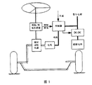
- FIG. 1 is a schematic structural diagram of an energy dynamic control system of a composite power supply EPS
- FIG. 2 is a schematic diagram of a DC-DC control of a composite power supply
- Figure 3 is a schematic diagram of the energy flow of the entire vehicle
- Figure 4 is a flow chart of dynamic control of supercapacitor charge and discharge current.
- FIG. 1 is a schematic diagram of the structure of the energy dynamic control system of the composite power supply EPS, including steering controller, steering wheel torque and angle sensor, DC-DC controller, steering assist motor, recirculating ball steering, vehicle power supply and super capacitor, steering wheel
- the moment and angle sensor are mounted on the steering column, the steering column is fixed at the top of the steering column, the bottom end of the steering column is connected to the recirculating ball steering gear, the recirculating ball steering device is hinged to the wheel hinge, the recirculating ball steering device and the steering assist motor Engagement, steering wheel torque and angle sensor collect steering wheel torque and angle signal, vehicle speed sensor collects vehicle speed signal, which are used as input of steering controller.
- Steering controller also collects vehicle power demand and formulates distribution control strategy to control DC-DC.
- Controller and steering assist motor DC-DC controller controls supercapacitor charge and discharge, steering assist motor output steering assist to recirculating ball steering, realizes steering of the whole vehicle; steering controller, DC-DC controller and vehicle power supply Connected, the vehicle power supply and the super capacitor jointly power the steering assist motor.
- the torque and angle sensors collect the torque and angle signals and send them to the steering controller.
- the steering controller also collects the vehicle speed and the vehicle power signal. Through the target current control algorithm, the steering motor can be determined.
- the target assist current; the steering controller regulates the DC-DC controller, so that the super capacitor and the vehicle power supply are combined under different working conditions, and the appropriate current is output to the steering assist motor, thereby driving the circulating ball steering device.
- FIG. 2 is a schematic diagram of the DC-DC control of the composite power supply.
- the supercapacitor equivalent mathematical model, the bidirectional half-bridge DC-DC converter, the steering motor, and the vehicle power supply are sequentially connected in parallel.
- the equivalent mathematical model of the supercapacitor is shown in the left block diagram.
- the leakage current resistance EPR characterizes the leakage current effect of the supercapacitor.
- the equivalent series resistance ESR is the parameter that affects the long-term energy storage of the supercapacitor.
- C is the capacitance characteristic of the super capacitor. EPR is connected in parallel with C and connected to the ESR.
- the middle block diagram shows A bidirectional half-bridge DC-DC converter in which a capacitor is connected in series with an insulated gate bipolar transistor in parallel with another insulated gate bipolar transistor, and finally connected in series with an inductor; the super capacitor is converted by a bidirectional half-bridge DC-DC converter
- the device is connected in parallel with the vehicle power supply to supply power to the steering motor.
- the steering controller detects the power requirements of the vehicle's electrical appliances, steering motors and supercapacitors under different driving conditions, and formulates corresponding power allocation strategies for transmission to the control circuit.
- the inductor current sampling circuit and the super capacitor voltage sampling circuit respectively detect the real-time current value and voltage value of the super capacitor, and send it to the control circuit, and the control circuit combines the control signal sent by the steering controller to perform the DC-DC converter through the PWM circuit. Regulation, so as to achieve the purpose of dynamic control of super capacitor charging and discharging current.
- the power distribution strategy is: when the vehicle speed is low, the vehicle power supply and the super capacitor jointly provide steering power for the steering motor, and the steering controller determines the manner and proportion of the steering power provided by the vehicle power supply and the super capacitor according to the vehicle speed and the steering wheel angle.
- the vehicle power supply separately provides the steering power for the motor.
- the super capacitor acts as the load of the power system, and is in the state of charge. The stored energy is used for low-speed steering; when the vehicle power supply fails, the super capacitor is separate.
- the composite power supply EPS has three power supply modes: a composite power supply mode, a vehicle power supply mode, and a super capacitor power supply mode.
- Figure 3 is a schematic diagram of the energy flow of the whole vehicle.
- the power supply from the generator is divided into three parts: The first part is used to supply power for the vehicle (except the steering motor and super capacitor). In this embodiment, the vehicle is used. (In addition to steering motors and supercapacitors) as a whole; the second part is used to charge the super capacitor; the third part is used to power the steering motor.
- Figure 4 is a flow chart of the dynamic control principle of the supercapacitor charge and discharge current, that is, the dynamic control method of the supercapacitor charge and discharge current of the composite power supply EPS, comprising the following steps:
- Step 1 Collect the real-time electric current I EB of the vehicle electric appliance, the target assist current I M of the steering motor, the real-time electric current I EB of the electric vehicle, and the target assist current I M of the steering motor by the following method :
- Step 1.1 The real-time electric current I EB of the vehicle electrical equipment (excluding the steering motor and super capacitor) can be collected and summed by adding a current sampling circuit to each power supply branch of the generator;
- Step 1.2 The steering controller receives the torque T of the steering wheel, the rotation angle signal ⁇ , and the vehicle speed signal V, and calculates the target assist current I M of the current steering motor through the target current control algorithm.
- Step 1.3 The target current control algorithm is:
- Step 1.3.1 Construct a system dynamics model of the electric power steering system and build the model in MATLAB/SIMULINK;
- Step 1.3.2 Input different steering wheel torque, rotation angle and vehicle speed to the system model, and simulate the steering torque of the vehicle corresponding to the driving condition;
- Step 1.3.3 The steering torque of the vehicle is reduced by the steering torque of the driver under different working conditions, that is, the assisting torque that the steering assist motor should provide;
- Step 1.3.4 The target assist current of the motor can be calculated by the assist torque and the electromagnetic torque coefficient of the motor;
- Step 1.3.6 In the case where the steering wheel torque angle and the vehicle speed are known, the real-time target assist current can be obtained by the calculation function.
- Step 2 The steering controller determines the charging and discharging states of the super capacitor by calculating the difference I between the generator rated current I D and (I EB +I M );
- Step 2.1 The rated current I D of the generator is the factory original parameter of the generator, which can be found according to the motor manual;
- Step 2.2 The formula for calculating the difference I is:
- Step 2.3 Supercapacitor charging and discharging state determination: When the difference I is greater than zero, the super capacitor is controlled to be in a charging state; when the difference I is less than or equal to zero, the super capacitor is controlled to be in a discharging state.
- Step 3 Calculate the SOC of the super capacitor at this time
- Step 3.1 Through the charging and discharging test of the super capacitor, the highest voltage value V max when the super capacitor is fully charged and the lowest voltage value V min when the power is discharged are obtained;
- Step 3.2 Add a voltage sampling circuit at the super capacitor end, and measure the current voltage value V of the super capacitor;
- Step 3.3 The SOC of the supercapacitor is calculated by:
- Step 4 When the super capacitor is in the charging state, the maximum charging current I 1 is calculated from the SOC of the super capacitor in the charging state; when the super capacitor is in the discharging state, the maximum discharging current I 2 is calculated from the SOC of the super capacitor in the discharging state. ;
- Step 4.1 When the supercapacitor is in the charging state, if the supercapacitor is fully charged in the minimum interval between the two extremely low speed steerings, the average charging current I 1 ' of the supercapacitor can be calculated by the following formula:
- T jmin is the minimum time interval between two extremely low speed steering of the car, which is obtained through the road test of the automobile;
- Q is the capacity of the selected super capacitor;
- the charging power of the super capacitor should not be too large, that is, the charging of the super capacitor should be limited.
- Current in this embodiment, the average charging current calculated by the equation (3) is selected as the limited supercapacitor maximum charging current, and the maximum charging current I 1 is calculated as follows:
- I 1 (1-SOC)*Q/T jmin (4)
- Step 4.2 When the super capacitor is in the discharge state, in order to enable the super capacitor to work in the high efficiency region, the discharge depth of the super capacitor cannot be too large, and the SOC' is selected as the lowest state of charge of the super capacitor; For the longest time, when the supercapacitor is discharged to the lowest state of charge, the average discharge current I' 2 of the supercapacitor can be calculated by the following formula:
- T max is the maximum time for a single low-speed steering of the car, which is obtained by the road test of the automobile;
- SOC' is the minimum amount of discharge of the super capacitor controlled to ensure the performance of the supercapacitor;
- the discharge power of the super capacitor can not be too large, that is, To limit the discharge current of the supercapacitor; select the average discharge current calculated by equation (5) as the limit supercapacitor maximum discharge current, then the maximum discharge current I 2 is calculated as follows:
- I 2 (SOC-SOC')*Q/T max (6)
- Step 5 The steering controller obtains the difference current I′ by the difference between the generator current I′ D and the (I EB +I M ) of the optimal working area of the generator;
- Step 5.1 The generator current I' D of the optimal working area of the generator is obtained by testing the efficiency of the generator;
- Step 5.2 The difference between the generator current I' D and (I EB +I M ) in the optimal working area of the generator is calculated as follows:
- Step 6 The steering controller calculates the charging and discharging current I C of the super capacitor
- Step 6.1 When it is determined that the super capacitor is in the charging state, compare the difference current I′ calculated in step 5 with the maximum charging current I 1 : if the difference current I′ does not exceed the maximum charging current I 1 at this time, Then the value of the supercapacitor charging current I C is taken as I', otherwise the value of I C is taken as I 1 ;
- Step 6.2 When the super capacitor is in the discharging state, compare the difference current I′ calculated by step 5 with the maximum discharging current I 2 ; if the absolute value of the difference current I′ does not exceed the maximum discharging current I at this time 2 , the value of the supercapacitor discharge current I C is taken as I', otherwise the value of I C is taken as -I 2 .
- Step 7 Control the power supply of the vehicle and the super capacitor to work in the power supply state determined by the charge and discharge state of the super capacitor: when the super capacitor is charged, the vehicle power supply is supplied; when the super capacitor is discharged, the vehicle power supply and the super capacitor are powered together. That is, the composite power supply, and the operating current of the super capacitor in the above two power supply modes is determined by step 6; if the power supply of the vehicle is faulty, the super capacitor is separately powered.
Landscapes
- Engineering & Computer Science (AREA)
- Physics & Mathematics (AREA)
- Geometry (AREA)
- Theoretical Computer Science (AREA)
- General Physics & Mathematics (AREA)
- Chemical & Material Sciences (AREA)
- Combustion & Propulsion (AREA)
- Transportation (AREA)
- Mechanical Engineering (AREA)
- General Engineering & Computer Science (AREA)
- Evolutionary Computation (AREA)
- Computer Hardware Design (AREA)
- Power Engineering (AREA)
- Automation & Control Theory (AREA)
- Aviation & Aerospace Engineering (AREA)
- Computational Mathematics (AREA)
- Mathematical Analysis (AREA)
- Mathematical Optimization (AREA)
- Pure & Applied Mathematics (AREA)
- Power Steering Mechanism (AREA)
- Steering Control In Accordance With Driving Conditions (AREA)
- Electric Propulsion And Braking For Vehicles (AREA)
Abstract
一种复合电源EPS的能量动态控制系统及方法,首先采集整车电器(除转向电机和超级电容)的实时工作电流,通过当前方向盘转矩和车速计算转向电机目标电流,通过发电机的额定电流与上面两电流之和的差值,判断超级电容的充电、放电状态。超级电容充电时,通过对充电电流的动态调整,使发电机处于最优工作区间,并基于当前的超级电容SOC限制其最大充电电流;超级电容放电时,通过对放电电流的动态调整,使发电机处于最优工作区间,并基于当前超级电容的SOC限制最大放电电流。基于此方法设计的超级电容充放电控制策略在满足EPS使用功能的前提下,可以使发电机在任何工况下都处于或者尽量靠近其最优工作区间,从而提升能源转化效率,降低能源消耗。
Description
本发明涉及汽车转向技术领域,尤其是用于商用车复合电源EPS的能量动态控制系统方法。
近年来,电动助力转向系统(Electric Power Steering,EPS)以其安全、节能、环保的优点广泛应用于乘用车和轻型商用车。EPS通过电机提供转向助力,助力大小由软件程序控制,可以方便地实现随速可变助力特性,有助于提高车辆的操纵稳定性,同时非转向工况下几乎不消耗电能,极大降低了能源消耗。由于具有上述的优点,转向系统的电动化,即电动助力转向(EPS)将是转向系统发展的方向。
EPS已成功应用于轻型商用车,然而重型商用车前轴载荷大,所需的转向功率较大,整车电源系统无法满足转向功率的需求,因而限制了EPS在重型商用车领域的应用。因此,研究适用于重型商用车的EPS新方案并解决新方案存在的科学问题和技术难题,具有重要的研究价值和现实意义。
超级电容作为一种新型的电源,具有充放电迅速,可实现大电流快速放电;动态性能好,循环效率高达90%~95%;控制简单、绿色环保等优点,因此,超级电容近年来较多的被用于发动机的启停辅助以及电动汽车的辅助电源等方面,以超级电容为辅助电源而构成的复合电源EPS的研究也在逐渐兴起。
作为电动助力转向系统应用的有效解决方案,国内外有部分学者已经对由超级电容配合整车电源而构成的复合电源EPS做过相关的研究。中国专利(CN103003134B)提出了一种检测具有主电源和辅助电源的EPS电源输出故障的系统及方法,实现对EPS尺寸和成本的降低;中国专利(CN103818329B)提出了一种由主电源对超级电容充电,并在恶劣路况转向时超级电容配合主电源提供驱动电流的方法;专利(JP2003320942A)提出了一种利用电容作为辅助电源的复合电源的电动助力转向系统,在低速工况时提供助力,以此减小主电源的容量并提高系统的适应性;专利(JP2007223510A)提出了一种延长辅助电源的工作时间,并且可较为方便的进行控制的电动助力转向辅助电源控制设备。以上专利均没有从能量分配和系统工作效率方面,对复合电源电动助力转向系统的设计与控制方法进行设计与改进。
发明内容
为了解决由于整车电源与超级电容能量调控不合理,导致转向助力不均衡和能源浪 费的问题,本发明提供了一种复合电源EPS的能量动态控制系统及方法,针对运用超级电容的复合电源电动助力转向系统,以能量均衡和提升能源转化效率为出发点,进行了控制策略与方法的改进,通过对电流的动态控制,以达到高效、节能的目的,为基于复合电源的EPS在重型商用车上的应用提供了一种合理有效的解决方案。
一种复合电源EPS的能量动态控制系统及方法,包括以下步骤:
步骤1:采集整车用电器(除转向电机和超级电容)的实时用电电流I
EB,转向助力电机的目标助力电流I
M;
步骤2:通过计算发电机额定电流I
D与(I
EB+I
M)的差值I,判定超级电容的充电、放电状态;
步骤3:计算出此时超级电容的SOC;
步骤4:当超级电容处于充电状态时,由此时超级电容的SOC计算出最大充电电流I
1;当超级电容处于放电状态时,由此时超级电容的SOC计算出最大放电电流I
2;
步骤5:通过计算发电机最优工作区的发电电流I'
D与(I
EB+I
M)的差值,得到差值电流I';
步骤6:计算超级电容的充放电电流I
C;
步骤7:控制整车电源及超级电容工作状态,包括整车电源供电状态或整车电源及超级电容供电状态或超级电容供电状态。
进一步的,所述步骤1中整车用电器的实时用电电流I
EB,转向电机的目标助力电流I
M通过下述方法得到:
步骤1.1:整车用电器(不包括转向电机和超级电容)的实时用电电流I
EB,可以通过在发电机各供电支路添加电流采样电路采集并求和得到;
步骤1.2:电动助力转向系统控制器接收到方向盘的转矩T、转角信号θ和车速信号V,通过目标电流控制算法计算出当前转向电机的目标助力电流I
M。
目标电流的控制算法为:
构建电动助力转向系统的系统动力学模型,并在MATLAB/SIMULINK中进行模型的搭建;对系统模型输入不同的方向盘转矩、转角以及车速等工况条件,仿真得到对应 行驶工况下输出的汽车转向阻力矩;汽车转向阻力矩减去不同工况下驾驶员的方向盘操作力矩,即为转向助力电机应当提供的助力力矩;由助力力矩结合电机的电磁转矩系数可计算得到电机的目标助力电流;由方向盘转矩、转角以及车速与目标助力电流的对应关系,构建不同行驶工况下的转向电机目标助力电流的计算函数:I=f(T,θ,V);在方向盘转矩转角以及车速已知的情况下,就可以通过该计算函数得到实时的目标助力电流。
进一步的,所述步骤2中发电机额定电流I
D与(I
EB+I
M)的差值I计算和超级电容充电、放电状态判定通过下述方法得到:
步骤2.1:通过发电机参数表查阅发电机的额定电流I
D;
步骤2.2:差值I的计算公式为:
I=I
D-(I
EB+I
M)
步骤2.3:超级电容充电、放电状态判定:当差值I大于零时,转向控制器通过PWM调控DC-DC变换器进行升压,超级电容处于充电状态;当差值I小于等于零时,转向控制器通过PWM调控DC-DC变换器进行降压,超级电容处于放电状态;
进一步的,所述步骤3中超级电容的SOC通过下述方法得到:
步骤3.1:通过超级电容的充电、放电试验测试,得到超级电容充满电时的最高电压值V
max和放完电的最低电压值V
min;
步骤3.2:在超级电容端添加电压采样电路,测量得到超级电容当前的电压值V;
步骤3.3:超级电容的SOC通过下式计算:
SOC=(V-V
min)/(V
max-V
min)
进一步的,所述步骤4中超级电容充电时的最大充电电流I
1和超级电容放电时最大放电电流I
2通过下述方法得到:
步骤4.1:当超级电容处于充电状态时,若在两次极低速转向的最小间隔时间内把超级电容的电量充满,则可以通过下式计算得到超级电容的平均充电电流I
1':
SOC+(T
jmin*I
1')/Q=1
式中:T
jmin为汽车两次极低速转向的最小时间间隔,通过汽车道路试验测试得到;Q为所选用超级电容的容量。
由上式计算得到的平均充电电流作为限制的超级电容最大充电电流,则最大充电电流I
1的计算公式如下:
I
1=(1-SOC)*Q/T
jmin
步骤4.2:当超级电容处于放电状态时,为了使超级电容能够工作在高效区,超级电容的放电深度不能过大,选取SOC'作为超级电容的最低荷电状态。若在单次极低速转向的最长时间内,超级电容放电到了最低荷电状态,则可以通过下式计算得到超级电容的平均放电电流I'
2:
SOC-(T
max*I'
2)/Q=SOC'
式中:T
max为汽车单次极低速转向的最长时间,通过汽车道路试验测试得到;SOC'为保证超级电容性能而控制的超级电容放电的最低电量;Q为所选用超级电容的容量。
由上式计算得到的平均放电电流作为限制的超级电容最大放电电流,则最大放电电流I
2的计算公式如下:
I
2=(SOC-SOC')*Q/T
max
进一步的,所述步骤5中差值电流I'的值通过下述方法得到:
步骤5.1:发电机最优工作区的发电电流I'
D通过对发电机进行效率测试得到;
步骤5.2:发电机最优工作区的发电电流I'
D与(I
EB+I
M)的计算公式如下:
I'=I'
D-(I
EB+I
M)
进一步,所述步骤6中超级电容的充放电电流通过下述方法得到:
步骤6.1:当判定超级电容处于充电状态时,将通过上述步骤计算得到的差值电流I'和最大充电电流I
1做比较。若差值电流I'不超过此时的最大充电电流I
1,则超级电容充电电流I
C的值取为I',否则I
C的值取为I
1;
步骤6.2:当超级电容处于放电状态时,将通过上述步骤计算得到的差值电流I'和最大放电电流I
2做比较。若差值电流I'的绝对值不超过此时的最大放电电流I
2,则超级电容放电电流I
C的值取为I',否则I
C的值取为-I
2。
复合电源EPS的能量动态控制系统,包括转向控制器、方向盘转矩和转角传感器、DC-DC控制器、转向助力电机、循环球转向器及超级电容,所述方向盘转矩和转角传感器安装于转向管柱上,所述转向管柱底端连接循环球转向器,所述循环球转向器与转向助力电机啮合,所述方向盘转矩和转角传感器采集方向盘转矩和转角信号作为转向控制器的输入,转向控制器还采集车速信号、整车功率需求,执行相应的功率分配策略,从而控制DC-DC控制器及转向助力电机,DC-DC控制器控制超级电容充放电,转向助力电机输出转向助力至循环球转向器;转向控制器通过判定超级电容的充放电状态、计算超级电容的充放电电流,控制整车电源及超级电容工作状态。
与现有技术相比,本发明的有益效果是:本发明的超级电容充电、放电控制策略,对超级电容的充电、放电状态和充电、放电电流的值进行动态调控,实现对发电机电流的高效分配利用,同时以此来削弱由于转向电机功率需求波动而造成的整车用电器的功率波动,在满足EPS使用功能的前提下,可以使发电机在任何工况下都处于或者尽量靠近其最优工作区间,从而提升能源转化效率,降低能源消耗。
图1为复合电源EPS的能量动态控制系统结构示意图;
图2为复合电源DC-DC控制原理图;
图3为整车能量流示意图;
图4为超级电容充放电电流动态控制流程图。
下面结合附图以及具体实施例对本发明做进一步的说明,但本发明的保护范围并不限于此。
图1为复合电源EPS的能量动态控制系统结构示意图,包括转向控制器、方向盘转矩和转角传感器、DC-DC控制器、转向助力电机、循环球转向器、整车电源及超级电容,方向盘转矩和转角传感器安装于转向管柱上,转向管柱顶端固定有方向盘,转向管柱底端连接循环球转向器,循环球转向器通过铰链机构与车轮铰链,循环球转向器还与转向助力电机啮合,方向盘转矩和转角传感器采集方向盘转矩和转角信号、车速传感器采集车速信号,均作为转向控制器的输入,转向控制器还采集整车功率需求,制定分配控制策略,从而控制DC-DC控制器及转向助力电机,DC-DC控制器控制超级电容充放电,转向助力电机输出转向助力至循环球转向器,实现整车的转向;转向控制器、DC-DC控制器均与整车电源相连,整车电源与超级电容共同为转向助力电机供电。
驾驶员转动方向盘时,转矩和转角传感器采集到转矩和转角信号并发送到转向控制器,转向控制器同时会采集车速、整车功率信号,通过目标电流控制算法,就可以确定转向电机的目标助力电流;转向控制器对DC-DC控制器进行调控,便可使超级电容和整车电源在不同工况下相复合,输出合适的电流到转向助力电机,从而推动循环球转向器工作。
图2为复合电源DC-DC控制原理图,超级电容等效数学模型、双向半桥DC-DC变换器、转向电机、整车电源依次并联,超级电容的等效数学模型如左框图所示,其中漏电流电阻EPR表征超级电容器的漏电流效应,等效串联电阻ESR为影响超级电容长期储能的参数,C为超级电容的电容特性,EPR与C并联后与ESR串联;中间框图所示为双向半桥DC-DC变换器,变换器由电容与绝缘栅双极型晶体管串联后与另一个绝缘栅双极型晶体管并联,最后再串联一个电感构成;超级电容通过双向半桥DC-DC变换器与整车电源并联,共同为转向电机供电。转向控制器检测到不同驾驶工况下整车用电器、转向电机和超级电容的功率需求,制定相应的功率分配策略,发送到控制电路。电感电流采样电路和超级电容电压采样电路分别检测到超级电容实时的电流值与电压值,发送到控制电路,控制电路结合转向控制器发送过来的控制信号,通过PWM电路对DC-DC变换器进行调控,从而实现对超级电容充放电电流动态控制的目的。
功率分配策略为:当车速较低时,整车电源和超级电容共同为转向电机提供转向功率,转向控制器根据车速、方向盘转角等信号决定整车电源和超级电容提供转向功率的方式和比例;当车速较高时,整车电源单独为电机提供转向功率,同时超级电容作为电源系统的负载,处于充电状态,存储的能量以备低速转向时使用;当整车电源发生故障时,超级电容单独为电机提供转向功率,维持短时间的转向助力;即复合电源EPS具有三种供电模式:复合电源供电模式、整车电源供电模式和超级电容供电模式。
图3为整车能量流示意图,将发电机发出的整车电源分为三部分:第一部分用于对整车用电器(除转向电机和超级电容)进行供电,本实施例将整车用电器(除转向电机和超级电容)作为一个整体考虑;第二部分用于对超级电容进行充电;第三部分用于对转向电机进行供电。
图4为超级电容充放电电流动态控制原理流程图,即复合电源EPS的超级电容充放电电流的动态控制方法,包括以下步骤:
步骤1:采集整车用电器的实时用电电流I
EB,转向电机的目标助力电流I
M;整车用 电器的实时用电电流I
EB,转向电机的目标助力电流I
M通过下述方法得到:
步骤1.1:整车用电器(不包括转向电机和超级电容)的实时用电电流I
EB,可以通过在发电机各供电支路添加电流采样电路采集并求和得到;
步骤1.2:转向控制器接收到方向盘的转矩T、转角信号θ和车速信号V,通过目标电流控制算法计算出当前转向电机的目标助力电流I
M。
步骤1.3:目标电流的控制算法为:
步骤1.3.1:构建电动助力转向系统的系统动力学模型,并在MATLAB/SIMULINK中进行模型的搭建;
步骤1.3.2:对系统模型输入不同的方向盘转矩、转角以及车速等工况条件,仿真得到对应行驶工况下输出的汽车转向阻力矩;
步骤1.3.3:汽车转向阻力矩减去不同工况下驾驶员的方向盘操作力矩,即为转向助力电机应当提供的助力力矩;
步骤1.3.4:由助力力矩,结合电机的电磁转矩系数可计算得到电机的目标助力电流;
步骤1.3.5:由步骤1.3.2-1.3.4得到的方向盘转矩、转角以及车速与目标助力电流的对应关系,构建不同行驶工况下的转向电机目标助力电流的计算函数:I=f(T,θ,V);
步骤1.3.6:在方向盘转矩转角以及车速已知的情况下,就可以通过该计算函数得到实时的目标助力电流。
步骤2:转向控制器通过计算发电机额定电流I
D与(I
EB+I
M)的差值I,判定超级电容的充电、放电状态;
判断超级电容充电、放电状态判定通过下述方法得到:
步骤2.1:发电机的额定电流I
D为发电机的出厂原始参数,可以根据电机说明书查到;
步骤2.2:差值I的计算公式为:
I=I
D-(I
EB+I
M) (1)
步骤2.3:超级电容充电、放电状态判定:当差值I大于零时,控制超级电容处于充电状态;当差值I小于等于零时,控制超级电容处于放电状态。
步骤3:计算出此时超级电容的SOC;
步骤3.1:通过超级电容的充电、放电试验测试,得到超级电容充满电时的最高电压值V
max和放完电的最低电压值V
min;
步骤3.2:在超级电容端添加电压采样电路,测量得到超级电容当前的电压值V;
步骤3.3:超级电容的SOC通过下式计算:
SOC=(V-V
min)/(V
max-V
min) (2)
步骤4:当超级电容处于充电状态时,由充电状态时超级电容的SOC计算出最大充电电流I
1;当超级电容处于放电状态时,由放电状态时超级电容的SOC计算出最大放电电流I
2;
步骤4.1:当超级电容处于充电状态时,若在两次极低速转向的最小间隔时间内把超级电容的电量充满,则可以通过下式计算得到超级电容的平均充电电流I
1':
SOC+(T
jmin*I
1')/Q=1 (3)
式中:T
jmin为汽车两次极低速转向的最小时间间隔,通过汽车道路试验测试得到;Q为所选用超级电容的容量;
为了能充分的发挥超级电容对整车用电器功率波动的补偿作用,更长时间的保证发电机处于或者靠近最优工作区间,超级电容的充电功率不应该过大,即要限制超级电容的充电电流;本实施例选取由式(3)计算得到的平均充电电流作为限制的超级电容最大充电电流,则最大充电电流I
1的计算公式如下:
I
1=(1-SOC)*Q/T
jmin (4)
步骤4.2:当超级电容处于放电状态时,为了使超级电容能够工作在高效区,超级电容的放电深度不能过大,选取SOC'作为超级电容的最低荷电状态;若在单次极低速转向的最长时间内,超级电容放电到了最低荷电状态,则可以通过下式计算得到超级电容的平均放电电流I'
2:
SOC-(T
max*I'
2)/Q=SOC' (5)
式中:T
max为汽车单次极低速转向的最长时间,通过汽车道路试验测试得到;SOC'为保证超级电容性能而控制的超级电容放电的最低电量;
为了满足EPS的使用性能要求,同时充分的发挥超级电容对整车用电器功率波动的补偿作用,使发电机能够更长时间处于或者靠近最优工作区间,超级电容的放电功率不能过大,即要限制超级电容的放电电流;选取由式(5)计算得到的平均放电电流作为限制的超级电容最大放电电流,则最大放电电流I
2的计算公式如下:
I
2=(SOC-SOC')*Q/T
max (6)
步骤5:转向控制器通过发电机最优工作区的发电电流I'
D与(I
EB+I
M)的差值,得到差值电流I';
步骤5.1:发电机最优工作区的发电电流I'
D通过对发电机进行效率测试得到;
步骤5.2:发电机最优工作区的发电电流I'
D与(I
EB+I
M)的差值计算公式如下:
I'=I'
D-(I
EB+I
M) (7)
步骤6:转向控制器计算超级电容的充放电电流I
C;
步骤6.1:当判定超级电容处于充电状态时,将通过步骤5计算得到的差值电流I'和最大充电电流I
1做比较:若差值电流I'不超过此时的最大充电电流I
1,则超级电容充电电流I
C的值取为I',否则I
C的值取为I
1;
步骤6.2:当超级电容处于放电状态时,将通过步骤5计算得到的差值电流I'和最大放电电流I
2做比较;若差值电流I'的绝对值不超过此时的最大放电电流I
2,则超级电容放电电流I
C的值取为I',否则I
C的值取为-I
2。
步骤7:控制整车电源及超级电容工作在由超级电容的充放电状态决定的供电状态:当超级电容充电时,整车电源供电;当超级电容放电时,整车电源及超级电容一起供电,即复合电源供电,且上述两种供电方式中超级电容的工作电流由步骤6确定;若整车电源故障时,超级电容单独供电。
所述实施例为本发明的优选的实施方式,但本发明并不限于上述实施方式,在不背离本发明的实质内容的情况下,本领域技术人员能够做出的任何显而易见的改进、替换或变型均属于本发明的保护范围
Claims (9)
- 复合电源EPS的能量动态控制方法,其特征在于,包括以下步骤:步骤1:采集除转向电机和超级电容之外的整车用电器的实时用电电流I EB及转向助力电机的目标助力电流I M;步骤2:通过计算发电机的额定电流I D与(I EB+I M)的差值I,判定超级电容的充电、放电状态;步骤3:计算此时超级电容的SOC;步骤4:当超级电容处于充电或放电状态时,由相应状态时超级电容的SOC计算出最大充电电流I 1或最大放电电流I 2;步骤5:计算发电机最优工作区的发电电流I' D与(I EB+I M)的差值,得到差值电流I';步骤6:计算超级电容的充电、放电电流I C;步骤7:由超级电容的充放电状态控制整车电源及超级电容工作状态。
- 根据权利要求1所述的复合电源EPS的能量动态控制方法,其特征在于,所述步骤1中数据采集的方法如下:步骤1.1:除转向电机和超级电容之外的整车用电器的实时用电电流I EB,通过在发电机各供电支路添加电流采样电路采集并求和得到;步骤1.2:转向控制器接收到方向盘的转矩T、转角信号θ和车速信号V,通过目标电流控制算法计算出当前转向电机的目标助力电流I M。
- 根据权利要求1所述的复合电源EPS的能量动态控制方法,其特征在于,所述步骤2具体为:步骤2.1:通过发电机参数表查阅发电机的额定电流I D;步骤2.2:判定超级电容充电、放电状态:当差值I大于零时,转向控制器通过PWM调控DC-DC变换器进行升压,超级电容处于充电状态;当差值I小于等于零时,转向控制器通过PWM调控DC-DC变换器进行降压,超级电容处于放电状态。
- 根据权利要求1所述的复合电源EPS的能量动态控制方法,其特征在于,所述步骤3中计算SOC通过下述步骤得到:步骤3.1:通过超级电容的充电、放电试验测试,得到超级电容充满电时的最高电压值V max和放完电的最低电压值V min;步骤3.2:在超级电容端添加电压采样电路,测量得到超级电容当前的电压值V;步骤3.3:超级电容的SOC通过公式计算:SOC=(V-V min)/(V max-V min)。
- 根据权利要求1所述的复合电源EPS的能量动态控制方法,其特征在于,所述最大充电电流I 1的计算方法为:I 1=(1-SOC)*Q/T jmin,其中T jmin为汽车两次极低速转向的最小时间间隔,Q为超级电容的容量;所述最大放电电流I 2的计算方法为:I 2=(SOC-SOC')*Q/T max,其中T max为汽车单次极低速转向的最长时间,SOC'为保证超级电容性能而控制的超级电容放电的最低电量。
- 根据权利要求1所述的复合电源EPS的能量动态控制方法,其特征在于,所述发电机最优工作区的发电电流I' D通过对发电机进行效率测试得到。
- 根据权利要求1所述的复合电源EPS的能量动态控制方法,其特征在于,所述步骤6具体为:步骤6.1:当超级电容处于充电状态时,将差值电流I'和最大充电电流I 1比较:若差值电流I'小于等于最大充电电流I 1,则超级电容充电电流I C的值取为I',否则I C的值取为I 1;步骤6.2:当超级电容处于放电状态时,将差值电流I'和最大放电电流I 2比较:若差值电流I'的绝对值小于等于最大放电电流I 2,则超级电容放电电流I C的值取为I',否则I C的值取为-I 2。
- 根据权利要求1所述的复合电源EPS的能量动态控制方法,其特征在于,所述整车电源及超级电容工作状态包括整车电源供电状态、整车电源及超级电容供电状态、超级电容供电状态。
- 复合电源EPS的能量动态控制系统,其特征在于,包括转向控制器、方向盘转矩和转角传感器、DC-DC控制器、转向助力电机、循环球转向器及超级电容,所述方向盘转矩和转角传感器安装于转向管柱上,所述转向管柱底端连接循环球转向器,所述循环球转向器与转向助力电机啮合,所述方向盘转矩和转角传感器采集方向盘转矩和转角信号作为转向控制器的输入,转向控制器还采集车速信号、整车功率需求,执行相应的功率分配策略,从而控制DC-DC控制器及转向助力电机,DC-DC控制器控制超级电容充放电,转向助力电机输出转向助力至循环球转向器;转向控制器通过判定超级电容的充放电状态、计算超级电容的充放电电流,控制整车电源及超级电容工作状态。
Priority Applications (1)
| Application Number | Priority Date | Filing Date | Title |
|---|---|---|---|
| US16/627,980 US11130517B2 (en) | 2018-05-09 | 2018-05-23 | Energy dynamic control system and method for the EPS with hybrid power supply |
Applications Claiming Priority (2)
| Application Number | Priority Date | Filing Date | Title |
|---|---|---|---|
| CN201810438771.7A CN108622187B (zh) | 2018-05-09 | 2018-05-09 | 复合电源eps的能量动态控制系统及方法 |
| CN201810438771.7 | 2018-05-09 |
Publications (1)
| Publication Number | Publication Date |
|---|---|
| WO2019213993A1 true WO2019213993A1 (zh) | 2019-11-14 |
Family
ID=63692377
Family Applications (1)
| Application Number | Title | Priority Date | Filing Date |
|---|---|---|---|
| PCT/CN2018/087960 Ceased WO2019213993A1 (zh) | 2018-05-09 | 2018-05-23 | 复合电源eps的能量动态控制系统及方法 |
Country Status (3)
| Country | Link |
|---|---|
| US (1) | US11130517B2 (zh) |
| CN (1) | CN108622187B (zh) |
| WO (1) | WO2019213993A1 (zh) |
Cited By (3)
| Publication number | Priority date | Publication date | Assignee | Title |
|---|---|---|---|---|
| CN111027203A (zh) * | 2019-12-05 | 2020-04-17 | 中车株洲电力机车有限公司 | 一种超级电容soc计算方法 |
| CN114079305A (zh) * | 2020-08-21 | 2022-02-22 | 北京交通大学 | 储能系统的控制系统、方法及储能系统 |
| CN114425954A (zh) * | 2022-03-03 | 2022-05-03 | 湖南城市学院 | 一种新能源电动车蓄电池复合电源的能量管理方法及系统 |
Families Citing this family (11)
| Publication number | Priority date | Publication date | Assignee | Title |
|---|---|---|---|---|
| CN109733467B (zh) * | 2019-01-24 | 2021-05-25 | 江苏大学 | 基于动态切换阈值的复合电源eps多模式切换方法及装置 |
| CN109733470B (zh) * | 2019-01-30 | 2021-08-03 | 江苏大学 | 一种重型商用车eps复合电源的多模式能量管理方法 |
| CN110001766B (zh) * | 2019-03-18 | 2021-04-20 | 江苏大学 | 一种复合电源eps故障模式下的助力特性曲线设计方法 |
| CN110717221B (zh) * | 2019-10-21 | 2023-09-22 | 中国航空工业集团公司沈阳飞机设计研究所 | 一种飞机能源需求精细化分析方法及设备 |
| CN110949496B (zh) * | 2019-11-15 | 2021-06-18 | 江苏大学 | 一种双油泵式混合动力电控转向系统及其控制方法 |
| CN112421746A (zh) * | 2020-11-09 | 2021-02-26 | 江苏科技大学 | 一种SC-Li-SC混合储能的充放电控制与管理方法及装置 |
| CN112906296B (zh) * | 2021-02-02 | 2022-05-10 | 武汉理工大学 | 混合动力汽车全服役期能量优化方法、系统和存储介质 |
| CN113014773B (zh) * | 2021-03-02 | 2023-08-01 | 山东鲁软数字科技有限公司智慧能源分公司 | 一种架空线路视频可视化监拍系统及方法 |
| CN113022481B (zh) * | 2021-03-17 | 2023-12-15 | 江苏大学 | 一种pmsc复合式半主动型馈能系统及其工作方法 |
| JP2022166477A (ja) * | 2021-04-21 | 2022-11-02 | 株式会社ジェイテクト | ステアリング装置 |
| GB2701362A (en) * | 2024-10-01 | 2026-04-29 | Jaguar Land Rover Ltd | Control system for controlling charging of an energy storage device |
Citations (6)
| Publication number | Priority date | Publication date | Assignee | Title |
|---|---|---|---|---|
| JP2001339872A (ja) * | 1995-04-14 | 2001-12-07 | Hitachi Ltd | ハイブリッドバッテリを備えた電気車の駆動装置及び制御方法 |
| CN201329893Y (zh) * | 2008-12-31 | 2009-10-21 | 众泰控股集团有限公司 | 一种电动汽车的电动助力转向系统 |
| CN101878135A (zh) * | 2007-11-28 | 2010-11-03 | 丰田自动车株式会社 | 电源控制装置 |
| CN103112491A (zh) * | 2012-12-28 | 2013-05-22 | 江苏大学 | 用于电动汽车的电动助力转向控制系统、装置及其方法 |
| CN103818329A (zh) * | 2014-03-06 | 2014-05-28 | 成都芝田高分子材料有限公司 | 基于超级电容器的汽车电子助力转向系统供电方法 |
| CN106427615A (zh) * | 2016-09-20 | 2017-02-22 | 江苏大学 | 一种复合电源控制系统及其在不同工况时的切换方法 |
Family Cites Families (12)
| Publication number | Priority date | Publication date | Assignee | Title |
|---|---|---|---|---|
| JP2003320942A (ja) * | 2002-04-26 | 2003-11-11 | Nsk Ltd | 電動パワーステアリング装置 |
| US7701079B2 (en) * | 2004-08-06 | 2010-04-20 | Continental Automotive Systems, Inc. | Automotive electrical system |
| JP2007091045A (ja) * | 2005-09-29 | 2007-04-12 | Jtekt Corp | 電動パワーステアリング装置 |
| JP4882417B2 (ja) | 2006-02-24 | 2012-02-22 | 株式会社ジェイテクト | 電動パワーステアリング装置 |
| JP4911231B2 (ja) * | 2010-02-15 | 2012-04-04 | 株式会社デンソー | 回転電機制御装置、および、これを用いた電動パワーステアリング装置 |
| JP5817162B2 (ja) | 2010-09-29 | 2015-11-18 | 株式会社ジェイテクト | 電動パワーステアリング装置 |
| JP6051803B2 (ja) * | 2012-11-15 | 2016-12-27 | 株式会社ジェイテクト | 電動パワーステアリング装置 |
| JP6115119B2 (ja) * | 2012-12-21 | 2017-04-19 | 株式会社ジェイテクト | 電動パワーステアリング装置 |
| US20140265559A1 (en) * | 2013-03-15 | 2014-09-18 | Levant Power Corporation | Vehicular high power electrical system |
| US9702349B2 (en) * | 2013-03-15 | 2017-07-11 | ClearMotion, Inc. | Active vehicle suspension system |
| CN103802821A (zh) * | 2014-02-19 | 2014-05-21 | 中国北方车辆研究所 | 基于混合动力用复合电源的动力控制方法 |
| WO2015153811A1 (en) * | 2014-04-02 | 2015-10-08 | Levant Power Corporation | Active safety suspension system |
-
2018
- 2018-05-09 CN CN201810438771.7A patent/CN108622187B/zh active Active
- 2018-05-23 US US16/627,980 patent/US11130517B2/en not_active Expired - Fee Related
- 2018-05-23 WO PCT/CN2018/087960 patent/WO2019213993A1/zh not_active Ceased
Patent Citations (6)
| Publication number | Priority date | Publication date | Assignee | Title |
|---|---|---|---|---|
| JP2001339872A (ja) * | 1995-04-14 | 2001-12-07 | Hitachi Ltd | ハイブリッドバッテリを備えた電気車の駆動装置及び制御方法 |
| CN101878135A (zh) * | 2007-11-28 | 2010-11-03 | 丰田自动车株式会社 | 电源控制装置 |
| CN201329893Y (zh) * | 2008-12-31 | 2009-10-21 | 众泰控股集团有限公司 | 一种电动汽车的电动助力转向系统 |
| CN103112491A (zh) * | 2012-12-28 | 2013-05-22 | 江苏大学 | 用于电动汽车的电动助力转向控制系统、装置及其方法 |
| CN103818329A (zh) * | 2014-03-06 | 2014-05-28 | 成都芝田高分子材料有限公司 | 基于超级电容器的汽车电子助力转向系统供电方法 |
| CN106427615A (zh) * | 2016-09-20 | 2017-02-22 | 江苏大学 | 一种复合电源控制系统及其在不同工况时的切换方法 |
Cited By (4)
| Publication number | Priority date | Publication date | Assignee | Title |
|---|---|---|---|---|
| CN111027203A (zh) * | 2019-12-05 | 2020-04-17 | 中车株洲电力机车有限公司 | 一种超级电容soc计算方法 |
| CN111027203B (zh) * | 2019-12-05 | 2023-05-02 | 中车株洲电力机车有限公司 | 一种超级电容soc计算方法 |
| CN114079305A (zh) * | 2020-08-21 | 2022-02-22 | 北京交通大学 | 储能系统的控制系统、方法及储能系统 |
| CN114425954A (zh) * | 2022-03-03 | 2022-05-03 | 湖南城市学院 | 一种新能源电动车蓄电池复合电源的能量管理方法及系统 |
Also Published As
| Publication number | Publication date |
|---|---|
| CN108622187B (zh) | 2019-10-01 |
| CN108622187A (zh) | 2018-10-09 |
| US20200156699A1 (en) | 2020-05-21 |
| US11130517B2 (en) | 2021-09-28 |
Similar Documents
| Publication | Publication Date | Title |
|---|---|---|
| CN108622187B (zh) | 复合电源eps的能量动态控制系统及方法 | |
| CN111762066B (zh) | 一种动力电池低温自加热装置、方法及纹波抑制方法 | |
| JP6749742B2 (ja) | 推進システムおよび車両駆動方法 | |
| CN106553557A (zh) | 应用于混合动力电动汽车的复合电源及功率分配控制方法 | |
| JP2007091122A (ja) | 電動パワーステアリング装置 | |
| CN108945089B (zh) | 一种基于功率需求的重型商用车eps复合电源的匹配方法 | |
| CN113879181A (zh) | 一种可以提高燃料电池使用寿命的实时能量管理控制方法 | |
| CN107332332A (zh) | 一种简化升压型电动汽车复合电源结构及其控制方法 | |
| CN117375465B (zh) | 一种中性点供电永磁同步电机母线升压控制方法 | |
| CN115021296B (zh) | 一种母线电压不控的电动汽车v2g双向直接功率控制方法 | |
| CN116552275B (zh) | 充放电控制方法、系统、装置、电动车辆和存储介质 | |
| CN114530913B (zh) | 一种48v系统低压蓄电池充电控制方法及汽车 | |
| CN103872729A (zh) | 自适应滤波器功率分流控制的混合动力车复合电源及方法 | |
| CN111114232A (zh) | 一种复合式电磁悬架的控制系统及其控制方法 | |
| CN104410086A (zh) | 天然气电站冲击负载动态补偿装置及方法 | |
| CN102001557A (zh) | 一种hybrid电梯控制柜及其控制方法 | |
| CN104156517A (zh) | 一种纯电动汽车复合电源系统效率计算模型和优化方法 | |
| Avelino et al. | Electric go-kart with battery-ultracapacitor hybrid energy storage system | |
| CN106849053B (zh) | 一种车载复合电源功率分配滑膜变结构控制方法 | |
| CN203747469U (zh) | 自适应滤波器功率分流控制的混合动力车复合电源 | |
| Du et al. | High-voltage bidirectional balancing structure and model predictive control for cell balancing of supercapacitors in heavy duty HEV applications | |
| Hanajiri et al. | Maximum efficiency operation in wider output power range of wireless in-wheel motor with wheel-side supercapacitor | |
| CN118508584A (zh) | 一种电动汽车混合储能系统电压反馈模型预测控制装置及方法 | |
| Wu et al. | Design of a soft switching bidirectional DC-DC power converter for ultracapacitor-battery interfaces | |
| CN114148178B (zh) | 一种电传动系统的控制方法及系统 |
Legal Events
| Date | Code | Title | Description |
|---|---|---|---|
| 121 | Ep: the epo has been informed by wipo that ep was designated in this application |
Ref document number: 18917985 Country of ref document: EP Kind code of ref document: A1 |
|
| NENP | Non-entry into the national phase |
Ref country code: DE |
|
| 122 | Ep: pct application non-entry in european phase |
Ref document number: 18917985 Country of ref document: EP Kind code of ref document: A1 |