WO2019208440A1 - ドローンを用いた消火システム - Google Patents
ドローンを用いた消火システム Download PDFInfo
- Publication number
- WO2019208440A1 WO2019208440A1 PCT/JP2019/016841 JP2019016841W WO2019208440A1 WO 2019208440 A1 WO2019208440 A1 WO 2019208440A1 JP 2019016841 W JP2019016841 W JP 2019016841W WO 2019208440 A1 WO2019208440 A1 WO 2019208440A1
- Authority
- WO
- WIPO (PCT)
- Prior art keywords
- drone
- fire
- fire extinguishing
- hose
- extinguishing system
- Prior art date
Links
- 239000007788 liquid Substances 0.000 claims abstract description 60
- 239000000446 fuel Substances 0.000 claims abstract description 40
- XLYOFNOQVPJJNP-UHFFFAOYSA-N water Substances O XLYOFNOQVPJJNP-UHFFFAOYSA-N 0.000 claims description 122
- 238000002347 injection Methods 0.000 claims description 26
- 239000007924 injection Substances 0.000 claims description 26
- 210000000078 claw Anatomy 0.000 claims description 14
- 238000002485 combustion reaction Methods 0.000 claims description 13
- 239000012530 fluid Substances 0.000 claims description 11
- 239000007800 oxidant agent Substances 0.000 claims description 8
- 230000001590 oxidative effect Effects 0.000 claims description 8
- 239000004449 solid propellant Substances 0.000 claims description 8
- 239000007787 solid Substances 0.000 claims description 5
- 239000000203 mixture Substances 0.000 claims description 2
- 238000005507 spraying Methods 0.000 abstract 1
- 238000010586 diagram Methods 0.000 description 28
- 230000004048 modification Effects 0.000 description 12
- 238000012986 modification Methods 0.000 description 12
- 230000000694 effects Effects 0.000 description 10
- 239000007789 gas Substances 0.000 description 10
- 239000000126 substance Substances 0.000 description 4
- 239000003795 chemical substances by application Substances 0.000 description 3
- 238000010248 power generation Methods 0.000 description 3
- 239000003651 drinking water Substances 0.000 description 2
- 235000020188 drinking water Nutrition 0.000 description 2
- 238000007689 inspection Methods 0.000 description 2
- 238000005086 pumping Methods 0.000 description 2
- MYMOFIZGZYHOMD-UHFFFAOYSA-N Dioxygen Chemical compound O=O MYMOFIZGZYHOMD-UHFFFAOYSA-N 0.000 description 1
- UFHFLCQGNIYNRP-UHFFFAOYSA-N Hydrogen Chemical compound [H][H] UFHFLCQGNIYNRP-UHFFFAOYSA-N 0.000 description 1
- 239000003990 capacitor Substances 0.000 description 1
- 229910001882 dioxygen Inorganic materials 0.000 description 1
- 238000005259 measurement Methods 0.000 description 1
- 238000000034 method Methods 0.000 description 1
- 238000012544 monitoring process Methods 0.000 description 1
- 239000008188 pellet Substances 0.000 description 1
- 239000000843 powder Substances 0.000 description 1
- 238000002360 preparation method Methods 0.000 description 1
- 239000002023 wood Substances 0.000 description 1
Images


Classifications
-
- B—PERFORMING OPERATIONS; TRANSPORTING
- B64—AIRCRAFT; AVIATION; COSMONAUTICS
- B64U—UNMANNED AERIAL VEHICLES [UAV]; EQUIPMENT THEREFOR
- B64U10/00—Type of UAV
- B64U10/60—Tethered aircraft
-
- A—HUMAN NECESSITIES
- A62—LIFE-SAVING; FIRE-FIGHTING
- A62C—FIRE-FIGHTING
- A62C27/00—Fire-fighting land vehicles
-
- B—PERFORMING OPERATIONS; TRANSPORTING
- B64—AIRCRAFT; AVIATION; COSMONAUTICS
- B64D—EQUIPMENT FOR FITTING IN OR TO AIRCRAFT; FLIGHT SUITS; PARACHUTES; ARRANGEMENTS OR MOUNTING OF POWER PLANTS OR PROPULSION TRANSMISSIONS IN AIRCRAFT
- B64D1/00—Dropping, ejecting, releasing, or receiving articles, liquids, or the like, in flight
- B64D1/16—Dropping or releasing powdered, liquid, or gaseous matter, e.g. for fire-fighting
-
- B—PERFORMING OPERATIONS; TRANSPORTING
- B64—AIRCRAFT; AVIATION; COSMONAUTICS
- B64D—EQUIPMENT FOR FITTING IN OR TO AIRCRAFT; FLIGHT SUITS; PARACHUTES; ARRANGEMENTS OR MOUNTING OF POWER PLANTS OR PROPULSION TRANSMISSIONS IN AIRCRAFT
- B64D1/00—Dropping, ejecting, releasing, or receiving articles, liquids, or the like, in flight
- B64D1/22—Taking-up articles from earth's surface
-
- B—PERFORMING OPERATIONS; TRANSPORTING
- B64—AIRCRAFT; AVIATION; COSMONAUTICS
- B64D—EQUIPMENT FOR FITTING IN OR TO AIRCRAFT; FLIGHT SUITS; PARACHUTES; ARRANGEMENTS OR MOUNTING OF POWER PLANTS OR PROPULSION TRANSMISSIONS IN AIRCRAFT
- B64D27/00—Arrangement or mounting of power plant in aircraft; Aircraft characterised thereby
- B64D27/02—Aircraft characterised by the type or position of power plant
- B64D27/16—Aircraft characterised by the type or position of power plant of jet type
-
- B—PERFORMING OPERATIONS; TRANSPORTING
- B64—AIRCRAFT; AVIATION; COSMONAUTICS
- B64D—EQUIPMENT FOR FITTING IN OR TO AIRCRAFT; FLIGHT SUITS; PARACHUTES; ARRANGEMENTS OR MOUNTING OF POWER PLANTS OR PROPULSION TRANSMISSIONS IN AIRCRAFT
- B64D27/00—Arrangement or mounting of power plant in aircraft; Aircraft characterised thereby
- B64D27/02—Aircraft characterised by the type or position of power plant
- B64D27/24—Aircraft characterised by the type or position of power plant using steam, electricity, or spring force
-
- B—PERFORMING OPERATIONS; TRANSPORTING
- B64—AIRCRAFT; AVIATION; COSMONAUTICS
- B64D—EQUIPMENT FOR FITTING IN OR TO AIRCRAFT; FLIGHT SUITS; PARACHUTES; ARRANGEMENTS OR MOUNTING OF POWER PLANTS OR PROPULSION TRANSMISSIONS IN AIRCRAFT
- B64D39/00—Refuelling during flight
-
- B—PERFORMING OPERATIONS; TRANSPORTING
- B64—AIRCRAFT; AVIATION; COSMONAUTICS
- B64F—GROUND OR AIRCRAFT-CARRIER-DECK INSTALLATIONS SPECIALLY ADAPTED FOR USE IN CONNECTION WITH AIRCRAFT; DESIGNING, MANUFACTURING, ASSEMBLING, CLEANING, MAINTAINING OR REPAIRING AIRCRAFT, NOT OTHERWISE PROVIDED FOR; HANDLING, TRANSPORTING, TESTING OR INSPECTING AIRCRAFT COMPONENTS, NOT OTHERWISE PROVIDED FOR
- B64F3/00—Ground installations specially adapted for captive aircraft
- B64F3/02—Ground installations specially adapted for captive aircraft with means for supplying electricity to aircraft during flight
-
- B—PERFORMING OPERATIONS; TRANSPORTING
- B64—AIRCRAFT; AVIATION; COSMONAUTICS
- B64U—UNMANNED AERIAL VEHICLES [UAV]; EQUIPMENT THEREFOR
- B64U10/00—Type of UAV
- B64U10/50—Glider-type UAVs, e.g. with parachute, parasail or kite
-
- B—PERFORMING OPERATIONS; TRANSPORTING
- B64—AIRCRAFT; AVIATION; COSMONAUTICS
- B64U—UNMANNED AERIAL VEHICLES [UAV]; EQUIPMENT THEREFOR
- B64U50/00—Propulsion; Power supply
- B64U50/10—Propulsion
- B64U50/11—Propulsion using internal combustion piston engines
-
- B—PERFORMING OPERATIONS; TRANSPORTING
- B64—AIRCRAFT; AVIATION; COSMONAUTICS
- B64U—UNMANNED AERIAL VEHICLES [UAV]; EQUIPMENT THEREFOR
- B64U50/00—Propulsion; Power supply
- B64U50/30—Supply or distribution of electrical power
- B64U50/31—Supply or distribution of electrical power generated by photovoltaics
-
- Y—GENERAL TAGGING OF NEW TECHNOLOGICAL DEVELOPMENTS; GENERAL TAGGING OF CROSS-SECTIONAL TECHNOLOGIES SPANNING OVER SEVERAL SECTIONS OF THE IPC; TECHNICAL SUBJECTS COVERED BY FORMER USPC CROSS-REFERENCE ART COLLECTIONS [XRACs] AND DIGESTS
- Y02—TECHNOLOGIES OR APPLICATIONS FOR MITIGATION OR ADAPTATION AGAINST CLIMATE CHANGE
- Y02T—CLIMATE CHANGE MITIGATION TECHNOLOGIES RELATED TO TRANSPORTATION
- Y02T50/00—Aeronautics or air transport
- Y02T50/60—Efficient propulsion technologies, e.g. for aircraft
Definitions
- the present invention relates to a fire extinguishing system using a drone, and more particularly, to a fire extinguishing system for transporting a nozzle of a fire hose connected to a drone to a high place.
- drones defined as unmanned moving bodies that move in the air and / or underwater are widely used in various fields such as photographing or monitoring, inspection or inspection, and measurement.
- the drone moves autonomously according to a preset purpose, or controls a human being using radio waves (radio waves, visible light, laser light of any wavelength band, sound waves, ultrasonic waves, or a combination thereof). It is steered by a person or controlled by an external control device (including a computer) through radio.
- a fire breaks out at a high place such as a high-rise floor
- the drone which is an unmanned mobile body, can transport the fire hose nozzle to the vicinity of the high floor where the fire is occurring, fire extinguishing can be performed safely and quickly.
- a drone is usually equipped with a power source (all kinds of power sources such as batteries, storage batteries, condensers, fuel cells, or fuel for combustion) and flies by power supplied from the power source. Due to the limited capacity of the power source that can be installed in the drone, the flight time of the drone is necessarily limited. For this reason, it is not possible to secure the flight time of the drone necessary to completely extinguish a fire that occurred in a high-rise building.
- an object of the present invention is to provide a fire extinguishing system capable of performing a sufficient fire extinguishing activity without causing a restriction on the flight time of the drone.
- One aspect of the present invention is a fire extinguishing hose having a nozzle for injecting a fire extinguishing liquid, a fire extinguishing liquid supply source connected to the fire extinguishing hose and supplying the fire extinguishing liquid to the fire extinguishing hose, and a top drone connected to the nozzle
- a fire extinguishing system comprising: a wired cable connected to the top drone; and a power supply device that supplies power or fuel for flying the top drone via the wired cable.
- the power supply device includes a power source that supplies electric power to the top drone, and the top drone includes a rotor blade or a rotor that is rotated by the electric power.
- the power supply device includes a pump device that supplies fuel to the top drone, and the top drone includes an internal combustion engine that rotates a rotor blade or a rotor by burning the fuel. It is characterized by.
- the power supply device includes a pump device that supplies jet fuel to the top drone, and the top drone includes a jet engine that obtains thrust by burning the jet fuel.
- the power supply device includes a pump device that supplies gaseous fuel and gaseous oxidant to the top drone, and the top drone burns the mixed fuel of the gaseous fuel and the gaseous oxidant. It has the gas rocket engine which obtains thrust by this.
- the power supply device includes a pump device that supplies solid fuel to the top drone, and the top drone has a solid rocket engine that obtains thrust by burning the solid fuel.
- the power supply device includes a pump device or a compressor that supplies pressurized fluid to the top drone, and the top drone includes an injection nozzle that obtains thrust by injecting the pressurized fluid. It is characterized by having.
- a preferred aspect of the present invention further includes at least one relay drone connected in the middle of the fire hose, and a relay cable connected to the relay drone, wherein the top drone and the relay drone are the wired cables. And the power or fuel for flying the top drone and the relay drone is supplied from the power supply device via the wired cable and the relay cable. .
- the preferable aspect of this invention is further equipped with the pressure
- a preferred embodiment of the present invention further comprises at least one auxiliary drone connected to the fire hose and an auxiliary wired cable connected to the auxiliary drone to adjust the posture of the fire hose, and the top
- the drone and the auxiliary drone are connected in series by the auxiliary wired cable, and power or fuel for flying the auxiliary drone is supplied from the power supply device via the wired cable and the auxiliary connecting cable. It is characterized by.
- the nozzle has a T-shape having a first branch pipe, a second branch pipe, and a third branch pipe, and the first branch pipe and the second branch pipe have the first branch pipe, Branching from the three branch pipes and extending in opposite directions, the fire extinguishing liquid flows into the third branch pipe and is jetted from the first branch pipe and the second branch pipe.
- the top drone includes an injection device for injecting an anchor.
- a solar cell panel is disposed on the top drone, and the solar cell panel supplies at least a part of electric power for driving the injection device to the injection device.
- the top drone includes an engagement hook, and the engagement hook has a claw that can be engaged with a rod-shaped member.
- the fire-extinguishing liquid supply source is a water supply system installed in a building, and the water supply system includes at least one pump and a water supply pipe extending from the pump.
- the hose has an attachment member that can be connected to the water supply system at an end thereof.
- the attachment member further includes a connection pipe or a connection hose for connecting the attachment member to the water supply system.
- the attachment member has a hose side connector for connecting the attachment member to a water supply side connector provided in a branch pipe of the water supply system, and the attachment member includes the hose side connector.
- a counterweight for maintaining the horizontal posture of the hose side connector is attached.
- the attachment member includes an opening / closing valve for opening / closing a flow path formed therein.
- the attachment member has a T-shape including a first branch portion, a second branch portion, and a third branch portion, and the first branch portion and the second branch portion are The fire extinguishing hose is branched from the third branch part and extends in opposite directions, and an opening / closing valve is disposed on each of the first branch part and the second branch part.
- the attachment member is configured as a drone provided with a thrust generation mechanism.
- the attachment member is connected to the relay drone.
- the top drone to which the nozzle of the fire hose is connected is always supplied with power or fuel from the power supply device via the wired cable, so the top drone has no restriction on the flight time.
- the top drone can be allowed to fly until the fire is completely extinguished.
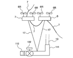
- Drawing 1 is a mimetic diagram showing signs that a fire which occurred in a high-rise building is extinguished using the fire extinguishing system concerning one embodiment.
- FIG. 2 is a schematic diagram showing a modification of the top drone.
- FIG. 3 is a schematic diagram showing another modification of the top drone.
- FIG. 4 is a schematic view showing a modified example of the nozzle of the fire hose.
- FIG. 5 is a schematic diagram showing still another modification of the top drone.
- FIG. 6 is a schematic diagram showing still another modification of the top drone.
- FIG. 7 is a schematic diagram showing still another modification of the top drone.
- Drawing 8 is a mimetic diagram showing signs that a fire which occurred in a high-rise building is extinguished using a fire extinguishing system concerning another embodiment.
- FIG. 9 is a schematic view showing that a fire that has occurred in a high-rise building is extinguished using a fire extinguishing system according to still another embodiment.
- FIG. 10 is a schematic view showing a part of a fire extinguishing system according to still another embodiment.
- FIG. 11A is an enlarged schematic diagram illustrating a branch pipe of the water supply system illustrated in FIG. 10.
- FIG. 11B is a schematic diagram showing a preparation stage for connecting the attachment member of the fire hose to the branch pipe of the water supply system shown in FIG. 10.
- FIG. 11C is a schematic diagram illustrating a state in which a fire hose is connected to the branch pipe of the water supply system illustrated in FIG. 10.
- Drawing 12 is a mimetic diagram showing signs that a fire hose is connected with a branch pipe of a water supply system via a connecting pipe.
- FIG. 13 is a schematic diagram illustrating a modification of the attachment member.
- FIG. 14 is a schematic view showing another modification of the attachment member.
- FIG. 15 is a schematic view showing still another modified example of the attachment member.
- FIG. 16 is a schematic view showing still another modified example of the attachment member.
- FIG. 17 is a schematic view showing still another modified example of the attachment member.
- Drawing 1 is a mimetic diagram showing signs that a fire which occurred in a high-rise building is extinguished using the fire extinguishing system concerning one embodiment.
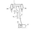
- a fire extinguishing system 100 shown in FIG. 1 is used to extinguish a fire of a high-rise building 105 such as a high-rise building.
- a fire extinguishing system 100 includes a fire hose 10 having a nozzle 11 for injecting a fire extinguishing liquid, a fire engine (fire extinguishing liquid supply source) 2 connected to the fire hose 10, and a nozzle 11.
- a top drone 1 a wired cable 4 connected to the top drone 1, and a power supply device 3 that supplies power or fuel for flying the top drone 1 to the top drone 1 via the wired cable 4. It is out.
- one end of the wired cable 4 is connected to the top drone 4 and the other end of the wired cable 4 is connected to the power supply device 3.
- the fire engine 2 shown in FIG. 1 functions as a fire-extinguishing liquid supply source that supplies the fire-extinguishing liquid to the fire hose 10.
- the fire engine 2 has a pump (not shown) for pumping out the fire-extinguishing liquid.
- Examples of fire extinguishing liquids include water and chemical fire extinguishing agents.
- the fire extinguishing liquid is water stored in the water storage tank 60.
- the fire engine 2 may have a tank for storing water or may be connected to a fire hydrant (not shown).
- the fire extinguisher is a chemical fire extinguisher
- the fire engine 2 has a tank for storing the chemical fire extinguisher.
- a liquid supply device that supplies the fire extinguishing liquid to the fire hose 10 may be disposed outside (for example, in the vicinity of) the fire engine 2 and the liquid supply apparatus may be connected to the fire engine 2.
- a liquid feeding device is, for example, a pump device capable of pumping water stored in the water storage tank 60.
- the fire engine 2 may be omitted, and a liquid feeding device such as a pump device may be directly connected to the water storage tank 60 or the fire hydrant.
- the liquid feeding device is a fire extinguishing liquid supply source, and the power supply device 3 and the control device 8 are arranged in the vicinity of the liquid feeding device.
- the top drone 1 is connected to the nozzle 11 of the fire hose 10 via a hanger 21 such as a wire.
- the top drone 1 has a rotary wing 1R, and the rotary wing 1R functions as a thrust generating mechanism that generates a thrust for causing the top drone 1 to fly.
- the hanger 21 may be omitted, and the nozzle 11 may be directly connected to the top drone 1.
- the power supply device 3 includes a power source 12, and is configured to supply the top drone 1 with power for rotating the rotor 1 ⁇ / b> R of the top drone 1 from the power source 12 via the wired cable 4.
- the rotor 1R of the top drone 1 is rotated by the electric power supplied from the power supply device 3 via the wired cable 4, and thereby the top drone 1 flies.
- the type of the power source 12 of the power supply device 3 is arbitrary, and for example, any type of power source such as a battery, a storage battery, a capacitor, or a fuel cell can be mounted on the power supply device 3.
- the power supply device 3 is mounted on the fire engine 2.
- a commercial power source (not shown) may be connected to the power supply device 3.
- the power supplied from the commercial power source is supplied to the top drone 1 via the power supply device 3 and the wired cable 4.
- a power generation device (not shown) may be installed to supply power to the power supply device 3 from the power generation device.
- the power supply device 3 is accommodated in the fire engine 2, but the present embodiment is not limited to this example. That is, the power supply device 3 may be disposed outside the fire engine 2 (for example, in the vicinity of the fire engine 2). In this case, a power generation device arranged in the vicinity of the fire engine 2 may be used as the power supply device 3.
- the fire extinguishing system 100 includes a control device 8 that controls the operation of the top drone 1 and the operation of the power supply device 3.
- the control device 8 may be a pilot operated by a human pilot or a computer storing a program for controlling the operation of the top drone 1.
- the top drone 1 operates wirelessly based on a control signal transmitted from the control device 8.
- the control device 8 may transmit a control signal to the top drone 1 via the wired cable 4.
- the control device 8 is also accommodated in the fire engine 2.
- the control device 8 may be arranged outside the fire engine 2 (for example, in the vicinity of the fire engine 2).
- the top drone 1 may have a rotor that is rotated by electric power instead of the rotor blade 1R.
- the rotor functions as a thrust generation mechanism that generates a thrust for flying the top drone 1. Electric power for rotating the rotor is supplied from the power supply device 3 to the top drone 1 via the wired cable 4.
- the fire extinguishing system 100 shown in FIG. 1 when a fire occurs in a high-rise building 105 such as a high-rise building, the fire is generated in the nozzle 11 of the fire hose 10 connected to the top drone 1 which is an unmanned moving body. It can be transported near the location. Therefore, fire extinguishing activities can be carried out safely and quickly. Furthermore, since power is always supplied to the top drone 1 from the power supply device 3 via the wired cable 4, it is not necessary to mount a power source on the top drone 1. Therefore, since the top drone 1 has no restriction on the flight time, the top drone 1 can be made to fly until the fire is completely extinguished.
- FIG. 2 is a schematic diagram showing a modification of the top drone 1.
- FIG. 2 shows a part of the high-rise building 105 shown in FIG.
- the top drone 1 may include an injection device 24 for injecting the anchor 25.
- the injection device 24 can fire the anchor 25 toward the wall surface of the high-rise building 105.
- the anchor 25 is injected from the injection device 24 toward the wall surface of the high-rise building 105 and driven into the wall surface of the high-rise building 105.
- the anchor 25 driven into the wall surface of the high-rise building 105 can prevent the fire hose 10 connected to the top drone 1 from moving. As a result, the posture of the fire hose 10 when the fire extinguishing liquid is sprayed from the nozzle 11 is maintained, and the fire extinguishing liquid can be discharged to a desired fire extinguishing position.
- the top drone 1 may include a solar cell panel 18.
- the electric power generated in the solar cell panel 18 can be used as power for operating the injection device 24.
- all or part of the electric power necessary for the injection mechanism 24 mounted on the top drone 1 can be covered by the electric power generated by the solar cell panel 18. Can do.
- FIG. 3 is a schematic diagram showing another modification of the top drone 1.
- the top drone 1 shown in FIG. 3 includes an engagement hook 26 instead of the injection mechanism 24.
- the engagement hook 26 has a claw 28 that can engage with a rod-shaped member 29 disposed adjacent to the high-rise building 105.
- a bar-shaped member 29 ′ that can engage the claw 28 of the engagement hook 26 may be fixed to the high-rise building 105.
- FIG. 3 shows an example of a bar-shaped member 29 ′ fixed to the high-rise building 105, and this bar-shaped member 29 ′ has a shape bent in a substantially U shape. Fixed to the wall.
- the plurality of rod-shaped members 29 ′ it is preferable to fix the plurality of rod-shaped members 29 ′ to the wall surface of the high-rise building 105.
- a plurality of bar-shaped members 29 ′ are arranged at equal intervals along the outer wall of the high-rise building 105, but the mounting positions of the bar-shaped members 29 ′ on the high-rise building 105 are arbitrary. Since the movement of the top drone 1 in the horizontal direction is prevented by engaging the claw 28 of the engagement hook 26 with the rod-shaped member 29 (or 29 ′), the fire extinguishing when the fire extinguishing liquid is ejected from the nozzle 11 The movement of the hose 10 can be prevented.
- the claw 28 of the engagement hook 26 may be configured as an electric claw that can be opened and closed by electric power.
- the engagement hook 26 is connected to the control device 8 (see FIG. 1), and the control device 8 controls the opening / closing operation of the claw 28 of the engagement hook 26.
- the power for opening and closing the claw 28 is supplied from the power supply device 3 via the wired cable 4.
- the control device 8 controls the opening / closing operation of the claw 28 so that the claw 28 grips the rod-shaped member 29 (or 29 ').
- the control device 8 may control an opening / closing operation of the claw 28 to grip an engagement member (not shown) such as an eyebolt or a fence provided on the wall surface of the high-rise building 105.
- an engagement member such as an eyebolt or a fence provided on the wall surface of the high-rise building 105.
- FIG. 4 is a schematic view showing a modified example of the nozzle of the fire hose.
- the nozzle 11 shown in FIG. 4 has a T-shape having a first branch pipe 11a, a second branch pipe 11b, and a third branch pipe 11c.
- the first branch pipe 11a and the second branch pipe 11b branch from the third branch pipe 11c and extend in opposite directions.
- the fire extinguishing liquid that has flowed through the fire hose 10 from the fire engine 2 (see FIG. 1) which is a fire extinguishing liquid supply source, flows into the third branch pipe 11c and is injected from the first branch pipe 11a and the second branch pipe 11b.
- the fire extinguishing liquid sprayed from the first branch pipe 11a is directed to the fire occurrence location.
- the force applied to the fire hose 10 when the fire extinguishing liquid is jetted from the first branch pipe 11a is offset by the force generated by jetting the fire extinguishing liquid from the second branch pipe 11b. Therefore, the movement of the fire hose 10 when the fire extinguishing liquid is being ejected from the nozzle 11 can be prevented.
- FIG. 5 is a schematic diagram showing still another modified example of the top drone 1.
- the top drone 1 shown in FIG. 5 has an internal combustion engine 13 that rotates the rotor blades 1R.
- the power supply device 3 includes a pump device 15 for supplying fuel to the internal combustion engine 13 of the top drone 1.
- the fuel supplied from the pump device 15 via the wired cable 4 is burned by the internal combustion engine 13, and the internal combustion engine 13 rotates the rotor blade 1R.
- the rotary wing 1 ⁇ / b> R generates a thrust for flying the top drone 1.
- the top drone may have a rotor rotated by the internal combustion engine 13 instead of the rotor blade 1R.
- a balloon 34 as an auxiliary flying body may be connected to the top drone 1.
- the balloon 34 can apply a vertical upward force to the top drone 1. Therefore, the weight of the fire hose 10 borne by the top drone 1 can be reduced by the balloon 34.
- An airship (not shown) may be used as an auxiliary flying body.
- FIG. 6 is a schematic diagram showing still another modified example of the top drone 1.
- the top drone 1 shown in FIG. 6 has an engine 35 instead of the rotor blade 1R.
- the engine 35 is used as a thrust generation mechanism that generates a thrust for flying the top drone 1.
- the engine 35 may be a jet engine using jet fuel, a gas rocket engine using a mixed fuel of gaseous fuel and gaseous oxidant, or a solid fuel containing a mixture of fuel and oxidant. It may be a solid rocket engine.
- the power generator 3 includes a pump device 15 for supplying fuel to the engine 35.
- the pump device 15 of the power supply device 3 supplies jet fuel to the top drone 1 via the wired cable 4.
- the jet fuel supplied from the power supply device 3 to the engine 35 via the wired cable 4 is mixed with air in the engine 35 and burned. Thereby, a thrust for flying the top drone 1 is generated.
- the pump device 15 of the power supply device 3 uses a gas cable (for example, hydrogen gas) and a gas oxidant (for example, oxygen gas) to the top drone 1 and the wired cable 4. Supply through.
- the gaseous fuel and gaseous oxidant supplied by the pump device 15 of the power supply device 3 are mixed and burned in the gas rocket engine. Thereby, the thrust which flies the top drone 1 generate
- the pump device 15 of the power supply device 3 supplies powdered or fine pellet-shaped solid fuel to the top drone 1 via the wired cable 4. More specifically, the pump device 15 is configured to pump a gas such as air containing a solid fuel in the form of powder or fine pellets to the engine 35 via the wired cable 4. The solid fuel supplied by the pump device 15 of the power supply device 3 is burned in the solid rocket engine, thereby generating a thrust force that causes the top drone 1 to fly.
- FIG. 7 is a schematic diagram showing still another modified example of the top drone 1.
- the top drone 1 shown in FIG. 7 has an injection nozzle 37 that injects a pressurized fluid (for example, compressed air, pressurized water, etc.) downward instead of the rotating blade 1R.
- the injection nozzle 37 is used as a thrust generation mechanism that generates a thrust for flying the top drone 1.
- the power supply device 3 supplies the pressurized fluid to the top drone 1 via the wired cable 4 and injects it from the injection nozzle 37. By injecting the pressurized fluid downward from the injection nozzle 37, thrust for flying the top drone 1 is generated. That is, the power supply device 3 supplies the pressurized fluid to the injection nozzle 37 of the top drone 1 as power for flying the top drone 1.
- the power supply device 3 When the fluid ejected from the ejection nozzle 37 is a liquid such as pressurized water, the power supply device 3 includes a pump device 15 that pumps the liquid to the top drone 1 via the wired cable 4. The liquid supplied to the top drone 1 from the pump device 15 via the wired cable 4 is jetted downward from the jet nozzle 37, thereby generating a thrust for flying the top drone 1.
- the power supply device 3 When the fluid ejected from the ejection nozzle 37 is a gas such as compressed air, the power supply device 3 includes the compressor 19, and the gas compressed by the compressor 19 is supplied to the top drone 1 via the wired cable 4. And is ejected from the ejection nozzle 37.
- FIG. 8 is a schematic diagram showing that a fire that has occurred in a high-rise building is extinguished using the fire extinguishing system 100 according to another embodiment.
- the configuration of the present embodiment that is not particularly described is the same as the configuration of the embodiment shown in FIG.
- Each relay drone 6 is connected in the middle of the fire hose 10 via a connector 17 such as a wire.
- a relay cable 7 is connected to each relay drone 6.
- the top drone 1 and the relay drone 6 are connected in series by a wired cable 4 and a relay cable 7. That is, the top drone 1 and the relay drone 6 adjacent to the top drone 1 are connected by the wired cable 4, and the adjacent relay drone 6 is connected by the relay cable 7.
- the relay cable 7 connected to the relay drone 6 located at the lowermost side (that is, the relay drone 6 adjacent to the power supply device 3) is connected to the power supply device 3. With such a configuration, the top drone 1 and the at least one relay drone 6 are connected in a chain by the wired cable 4 and the at least one relay cable 7.
- Each relay drone 6 has a rotary wing 6R, and the rotary wing 6R functions as a thrust generating mechanism that generates a thrust for flying the relay drone 6.
- Power for flying the top drone 1 and the relay drone 6 is supplied from the power supply device 3 via the wired cable 4 and the relay cable 7. More specifically, the power for flying the top drone 1 is supplied from the power supply device 3 via the wired cable 4 and the relay cable 7, and the power for flying each relay drone 6 is powered via the relay cable 7. Supplied from the supply device 3.
- each relay drone 6 operates wirelessly based on a control signal transmitted from the control device 8.
- the control device 8 may transmit a control signal to each relay drone 7 via the relay cable 7.
- the control device 8 controls the operation of the top drone 1 and the operation of each relay drone 6 independently of each other. Therefore, the control device 8 can cause the top drone 1 and the relay drone 6 connected in series by the wired cable 4 and the relay cable 7 to function as if they were one articulated robot arm. As a result, the fire hose 10, the wired cable 4, and the relay cable 7 are not caught on or tangled with a natural object (for example, wood) or an artificial object (for example, an electric wire).
- a natural object for example, wood
- an artificial object for example, an electric wire
- the control device 8 controls the flight operation of the top drone 1 and each relay drone 6 so that the nozzle 11 of the fire hose 10 reaches the vicinity of the fire occurrence point. Can do.
- a fire extinguishing activity is carried out by injecting a fire extinguishing liquid (for example, water, chemical fire extinguishing agent, etc.) from the nozzle 11 of the fire hose 10 that has reached the vicinity of the fire occurrence site.
- a fire extinguishing liquid for example, water, chemical fire extinguishing agent, etc.
- each relay drone 6 flies with a part of the weight of the fire hose 10, the weight of the fire hose 10 borne by the top drone 1 is reduced. More specifically, the weight of the fire hose 10 borne by the top drone 1 is the weight of a part of the fire hose 10 existing between the top drone 1 and the relay drone 6 adjacent to the top drone 1. Furthermore, the weight of the fire hose 10 borne by each relay drone 6 is the weight of a part of the fire hose 10 existing between the adjacent relay drones 6. Therefore, by increasing the number of relay drones 6, it is possible to eliminate the restriction of the high floor that the top drone 1 (that is, the nozzle 11 of the fire hose 10) can reach. In other words, the height at which the top drone 1 can reach can be adjusted by increasing the number of relay drones 6 according to the height of the fire occurrence site.
- the top drone 1 and the relay drone 6 are supplied with electric power from the power supply 12 of the power supply device 3 via the wired cable 4 and the relay cable 7. Therefore, there is no restriction on the flight time of the top drone 1 and the relay drone 6 during the fire fighting operation. As a result, the top drone 1 and the relay drone 6 can be made to fly until the fire is completely extinguished.
- each relay drone 6 may have an internal combustion engine that rotates the rotor blade 6R. Further, a balloon 34 (see FIG. 5) or an airship may be connected to the relay drone 6. Further, the relay drone 6 may have the engine 35 described with reference to FIG. 6 or the injection nozzle 37 described with reference to FIG. 7 instead of the rotor blade 6R. May be.
- the thrust generator of the top drone 1 and the thrust generator of the relay drone 6 may be different from each other.
- the thrust generator of the top drone 1 is the engine 35 that burns fuel
- the thrust generator of the relay drone 6 may be the rotor blade 6R that rotates by electric power.
- the power supply device 3 is configured to include a pump device 15 for supplying fuel to the engine 35 of the top drone 1 and a power source 12 for supplying power to the rotor blades 6R of the relay drone 6.
- each relay drone 6 may have the same thrust generating device, or may have different thrust generating devices.
- the thrust generators of some relay drones 6 may be the engine 35 that burns fuel, while the thrust generators of the remaining relay drones 6 may be the injection nozzles 37 that inject pressurized fluid.
- the power supply device 3 includes a pump device 15 for supplying fuel to the engines 35 of some relay drones 6 and another pump device 15 for supplying pressurized gas to the remaining relay drones 6 or And a compressor 19.
- the fire extinguishing system 100 may include at least one (two in FIG. 8) auxiliary drone 30.
- the fire extinguishing system 100 is divided into a main drone group in which the top drone 1 and the relay drone 6 are connected in series by the wired cable 4 and the relay cable 7, and at least one (FIG. 2) is branched from the middle of the main drone group. Then, two auxiliary drones 30 connected in series by an auxiliary wired cable 31 are included.
- Each auxiliary drone 30 is connected to the nozzle 11 of the fire hose 10 via a connector 32 such as a wire.
- the control device 8 controls the flight operation of the auxiliary drone 30 in addition to the flight operations of the top drone 1 and the relay drone 6.
- each auxiliary drone 30 has a rotary blade 30R that functions as a thrust generation mechanism. Electric power for rotating the rotor blades 30 ⁇ / b> R of each auxiliary drone 30 is supplied to each auxiliary drone 30 via the relay cable 7, the wired cable 4, and the auxiliary wired cable 31.
- the auxiliary drone 30 is connected to the fire hose 10 in order to control the posture of the fire hose 10 connected to the top drone 1. As described above, when the fire extinguishing liquid is jetted from the nozzle 11, a force in the direction opposite to the jetting direction of the fire extinguishing liquid acts on the fire hose 10.
- the control device 8 causes the auxiliary drone 30 to fly so that the auxiliary drone 30 pulls the nozzle 11 of the fire hose 10 in the fire extinguishing liquid injection direction when the fire extinguishing liquid is injected.
- the auxiliary drone 30 may have an internal combustion engine that rotates the rotary blade 30R. Further, a balloon 34 (see FIG. 5) or an airship may be coupled to the auxiliary drone 30. Further, the auxiliary drone 30 may include the engine 35 described with reference to FIG. 6 instead of the rotor blade 6R. Each auxiliary drone 30 may have the same thrust generating device, or may have different thrust generating devices.
- the thrust generator of the top drone 1, the thrust generator of the relay drone 6, and the thrust generator of the auxiliary drone 30 are They may be different from each other.
- FIG. 9 is a schematic diagram showing that a fire that has occurred in a high-rise building is extinguished using a fire extinguishing system 100 according to still another embodiment.
- the configuration of the present embodiment that is not particularly described is the same as the configuration of the embodiment shown in FIG.
- booster pump 40 is arranged in the middle of the fire hose 10.
- the booster pump 40 is used to increase the pressure of the extinguishing agent flowing through the fire hose 10.
- one booster pump 40 is disposed in the middle of the fire hose 10, but a plurality of booster pumps 40 may be disposed in the middle of the fire hose 10.
- two relay drones 6 among the plurality of relay drones 6 are connected to the booster pump 40 via a connector 17 such as a wire.
- the number of relay drones 6 connected to the booster pump 40 may be one or three or more.
- control device 8 controls the operation of the top drone 1 and the operation of each relay drone 6 independently of each other. Accordingly, as shown in FIG. 9, a plurality of relay drones 6 connected in series by the relay cable 7 can function as if they were one articulated robot arm.
- the weight of the booster pump 40 is borne by at least one relay drone 6.
- the booster pump 40 it is possible to reduce the size of a pump (not shown) that is mounted on the fire engine 2 and pumps the fire-extinguishing liquid. Further, the pressure of the fire extinguishing liquid flowing in the fire hose 10 can be reduced as compared with the case where the fire extinguishing liquid is pumped by one pump mounted on the fire engine 2. As a result, the pressure resistance performance of the fire hose 10 can be reduced, so that an inexpensive and lightweight fire hose 10 can be used.
- the fire extinguishing system shown in FIG. 9 may have the auxiliary drone 30 described with reference to FIG.
- the auxiliary drone 30 controls the posture of the fire hose 10 connected to the top drone 1.
- the nozzle 11 of the fire hose 10 may have the T shape described with reference to FIG. 4.
- FIG. 10 is a schematic view showing a part of a fire extinguishing system 100 according to still another embodiment. More specifically, FIG. 10 shows a portion from the extinguishing liquid supply source of the fire extinguishing system 100 to the end of the fire hose.
- the configuration of the present embodiment that is not particularly described is the same as the configuration of the above-described embodiment, and thus redundant description thereof is omitted.
- the water supply system 102 disposed in the high-rise building 105 where a fire is occurring functions as the fire extinguishing liquid supply source 2 described above. That is, the fire hose 10 connected to at least one drone 1, 6 is connected to the water supply system 102, and water as a fire extinguishing liquid is supplied from the water supply system 102 to the fire hose 10.
- the fire hose 10 may be coupled to a water supply system that is located in a building (eg, a building adjacent to the high-rise building 105) that is different from the high-rise building 105 in which a fire is occurring.
- the water supply system 102 includes a plurality of water supply devices 106 and a water supply pipe 108 extending from each of the water supply devices 106.
- a plurality of (three) water supply devices 106 arranged on a plurality of floors are depicted, but the number of water supply devices 106 is not limited to this example.
- the water supply system 102 may have only one water supply device 106. That is, the water supply system 102 only needs to have at least one water supply device 106.
- Each water supply device 106 includes a water supply pump 115 that increases the pressure of water flowing in the water supply device 106.
- the water supply system 102 includes a plurality of water supply devices 106
- the adjacent water supply devices 106 are connected by a water supply pipe 108.
- Each water supply pipe 108 has a main pipe 108a and a branch pipe 108b branched from the main pipe 108a.
- the water supply device 106 located on the lowermost side has an inlet pipe 106a connected to the water pipe 200, and the water flowing through the water pipe 200 is located on the lowermost side via the inlet pipe 106a. Sucked into.
- Such a water supply system 102 is, for example, a drinking water supply system that supplies drinking water into the high-rise building 105.
- the water supply system 102 may be a sprinkler system disposed in the high-rise building 105.
- the branch pipe 108b has a water supply side connector 109 at its end.
- An attachment member 111 is provided at the end of the fire hose 10, and the attachment member 111 includes a hose side connector 113 configured to be detachable from the water supply side connector 109 of the branch pipe 108b.
- the water supply side connector 109 of the branch pipe 108b and the hose side connector 113 of the attachment member 111 function as a joint 110 that connects the fire hose 10 to the branch pipe 108b of the water supply pipe 108.
- Examples of the joint 110 include a screw-in joint and a one-touch joint.
- the fire hose 10 When the joint 110 is a one-touch joint, the fire hose 10 is connected to the branch pipe 108b via the attachment member 111 only by inserting the hose connector 113 into the water supply connector 109. Therefore, the fire hose 10 can be quickly connected to the branch pipe 108b of the water supply pipe 108 (that is, the water supply system 102 that is a fire extinguishing liquid supply source).
- the attachment member 111 has an L-shaped cross-sectional shape.
- the hose connector 113 is disposed at one end (that is, the tip) of the attachment member 111, and the other end (that is, the end) is connected to the fire hose 10.
- the attachment member 111 has a flow path (not shown) through which water supplied from the water supply pipe 108 of the water supply system 102 flows. Therefore, when the hose connector 113 of the attachment member 111 is connected to the water supply connector 109 provided at the tip of the branch pipe 108b, the fire hose 10 communicates with the water supply pipe 108 of the water supply system 102 via the attachment member 111. Thereby, water as a fire extinguishing liquid can be supplied from the water supply system 102 to the fire hose 10.
- the power supply device 3 and the control device 8 described above are arranged on the ground.
- the fire hose 10 is connected to a plurality of drones 1 and 6.
- Power is supplied to the plurality of drones 1 and 6 from the power supply 12 of the power supply device 3 via the wired cable 4 and the relay cable 7. Therefore, there is no restriction on the flight time of the top drone 1 and the relay drone 6 during the fire fighting operation.
- the top drone 1 and the relay drone 6 can be made to fly until the fire is completely extinguished.
- water (fire extinguishing liquid) flowing through the water pipe 200 can be supplied to the fire hose 10 connected to the water supply system 102. Therefore, theoretically, there is no limit to the amount of water supplied to the fire hose 10.
- the fire extinguishing system shown in FIG. 10 may have the auxiliary drone 30 described with reference to FIG. 8, and the booster pump (relay pump) 40 described with reference to FIG. You may arrange
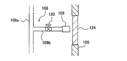
- FIG. 11A to FIG. 11C are schematic diagrams for explaining a process of connecting the attachment member 111 shown in FIG. 10 to the water supply system 102. More specifically, FIG. 11A is an enlarged schematic view showing the branch pipe 108b of the water supply system 102 before the attachment member 111 is connected, and FIG. 11B is a fire hose on the branch pipe 108b of the water supply system 102. FIG. 11C is a schematic diagram illustrating a state in which the fire hose 10 is coupled to the branch pipe 108 b of the water supply system 102.
- the branch pipe 108b is provided with an on-off valve 120.
- the on-off valve 120 is normally closed.
- the on-off valve 120 is opened, water in the main pipe 108a of the water supply pipe 108 flows through the branch pipe 108b.
- the water supply side connector 109 provided at the tip of the branch pipe 108 b is adjacent to the emergency opening / closing window 124 provided on the wall surface of the high-rise building 105.
- the emergency opening / closing window 124 is normally closed.
- the water supply side connector 109 may be adjacent to an emergency door (not shown) provided on the wall surface of the high-rise building 105.
- the water supply side connector 109 may protrude outside from the wall surface of the high-rise building 105.
- the emergency opening / closing window 124 is opened (or removed) as shown in FIG. 11B.
- the operations of the plurality of drones 1 and 6 are controlled so that the hose connector 113 of the attachment member 111 connected to the end of the fire hose 10 faces the water supply connector 109 provided at the tip of the branch pipe 108b. 8 is controlled.
- an operator for example, a fire brigade
- the operator opens the on-off valve 120 provided in the branch pipe 108b, so that water (extinguishing liquid) is supplied from the water supply system 102 to the fire hose 10.
- FIG. 12 is a schematic diagram showing a state in which the fire hose 10 is connected to the branch pipe 108b of the water supply system 102 via the connection pipe 125. As shown in FIG. 12, the fire hose 10 may be connected to the branch pipe 108b via the connecting pipe 125.
- a first connecting pipe connector 125a configured to be detachable from the water supply side connector 109 provided at the tip of the branch pipe 108b of the water supply system 102 is provided.
- the water supply side connector 109 of the branch pipe 108b and the first connection pipe connector 125a of the connection pipe 125 function as a joint 110a that connects the connection pipe 125 to the branch pipe 108b.
- Examples of the joint 110a include a screw joint and a one-touch joint.
- the other end of the connecting pipe 125 is provided with a second connecting pipe connector 125b configured to be detachable from the hose connector 113 of the attachment member 111.
- the hose side connector 113 of the attachment member 111 and the second connection tube connector 125 b of the connection tube 125 function as a joint 110 b that connects the connection tube 125 to the attachment member 111.
- Examples of the joint 110b include a screw-in joint and a one-touch joint.
- the first connection pipe connector 125a of the connection pipe 125 is connected to the water supply side connector 109 of the branch pipe 108b, and the second connection pipe connector 125b of the connection pipe 125 is connected to the hose side connector 113 of the attachment member 111, thereby extinguishing the fire.
- the hose 10 is connected to the water supply system 102 via the connecting pipe 125.
- a flexible connecting hose having a first connecting pipe connector 125a and a second connecting pipe connector 125b may be used. With such a configuration, the fire hose 10 can be connected to the water supply system 102 even if the branch pipe 108 b is separated from the wall surface of the high-rise building 105.
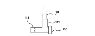
- FIG. 13 is a schematic diagram showing a modification of the attachment member 111.
- a counterweight 130 may be attached to a bent portion of an attachment member 111 having an L shape.
- the counterweight 130 is a weight attached to the attachment member 111 so that the hose connector 113 maintains a horizontal posture. Since the counter weight 130 allows the hose side connector 113 to maintain a horizontal posture, the workability of connecting the hose side connector 113 to the water supply side connector 109 of the branch pipe 108b (or the second connection pipe connector 125b of the connection pipe 125) is improved. improves.
- FIG. 14 is a schematic diagram showing another modification of the attachment member 111.
- the attachment member 111 shown in FIG. 14 includes an opening / closing valve 132 that can open and close a flow path formed inside the attachment member 111 in addition to the counterweight 130.
- the supply of water to the fire hose 10 is started by opening the on-off valve 132.
- the on-off valve 132 By closing the on-off valve 132 after the fire fighting operation is completed, the water remaining in the fire hose 10 is prevented from flowing back to the water supply system 102.
- the attachment member 111 when the attachment member 111 is removed from the branch pipe 108b of the water supply system 102, the water remaining in the fire hose 10 can be prevented from scattering into the high-rise building 105 by closing the on-off valve 132. .
- the counterweight 130 may be omitted.
- FIG. 15 is a schematic diagram showing still another modified example of the attachment member 111.
- the attachment member 111 shown in FIG. 15 has a T shape having a first branch part 111a, a second branch part 111b, and a third branch part 111c.
- the first branch part 111a and the second branch part 111b branch from the third branch part 111c and extend in opposite directions.
- the extremity of the fire hose 10 is connected to the third branch portion 111c, and the hose-side connector 113 described above is disposed at the distal end of the first branch portion 111a.
- the above-described on-off valve 132 is disposed between the connection portion between the first branch portion 111 a and the third branch portion 111 c and the hose side connector 113.
- a hose connector 116 having the same configuration as that of the hose connector 113 is disposed at the tip of the second branch portion 111b.
- the on-off valve 134 which has the same structure as the on-off valve 132 mentioned above is arrange
- either the hose side connector 113 or the hose side connector 116 can be connected to the water supply side connector 109 of the branch pipe 108b. Therefore, if the worker who performs fire fighting activity catches either the hose side connector 113 or the hose side connector 116, the fire hose 10 can be connected to the water supply system 102, so the workability of the fire fighting activity is improved. To do.
- the hose side connector 113 (or the hose side connector 116) is connected to the water supply side connector 109 of the branch pipe 108b
- the on / off valve 132 or on / off valve 134
- the on / off valve 134 or on / off valve 132
- first branch part 111a and the second branch part 111b are arranged mirror-symmetrically with respect to the third branch part 111c. Furthermore, it is preferable that the on-off valve 132 and the on-off valve 134 are also arranged mirror-symmetrically with respect to the third branch portion 111c. With such a configuration, the horizontal posture of the hose side connector 116 and the hose side connector 113 can be maintained without providing a counterweight.
- FIG. 16 is a schematic diagram showing still another modified example of the attachment member 111.
- the attachment member 111 shown in FIG. 16 is configured as a drone provided with a rotating blade 111R that functions as a thrust generating mechanism.
- a relay cable 7 extending from the power supply device 3 (see FIG. 10) is connected to the attachment member 111, and electric power for rotating the rotating blades 111R is transmitted from the power supply device 3 to the attachment member 111 via the relay cable 7. Supplied. Electric power is supplied to the relay drone 6 positioned above the attachment member 111 by the relay cable 7 extending from the attachment member 111.
- the attachment member 111 can be easily brought close to the water supply side connector 113 of the branch pipe 108b.
- the joint 110 constituted by the water supply side connector 109 of the branch pipe 108b and the hose side connector 113 of the attachment member 111 is a one-touch joint
- the control device 8 automatically controls the operation of the attachment member 111
- the hose side connector 113 of the attachment member 111 can be connected to the water supply side connector 109 of the branch pipe 108b.
- this attachment member 111 since the fire hose 10 can be easily and automatically connected to the water supply system 102, workability of fire fighting activities is improved.
- the attachment member 111 configured as a drone may have an internal combustion engine that rotates the rotor blades 111R.
- the attachment member 111 may have a rotor that is rotated by electric power or an internal combustion engine instead of the rotor blade 111R, or may have the engine 35 described with reference to FIG. And you may have the injection nozzle 37 demonstrated with reference to FIG.
- FIG. 17 is a schematic diagram showing still another modified example of the attachment member 111.
- the attachment member 111 shown in FIG. 17 is connected to a plurality (two in the present embodiment) of the relay drones 6 via a connector 17 such as a wire.
- the attachment member 111 may be connected to only one relay drone 6.
- the control device 8 can control the operation of the relay drone 6 connected to the attachment member 111 so that the hose side connector 113 of the attachment member 111 can be brought close to or connected to the water supply side connector 109 of the branch pipe 108b.
- the control device 8 can maintain the horizontal posture of the hose connector 116 by controlling the operation of the relay drone 6 connected to the attachment member 111. Therefore, according to the attachment member 111 concerning this embodiment, since the fire hose 10 can be easily connected with the water supply system 102, workability
- the present invention can be used in a fire extinguishing system for conveying a fire hose nozzle connected to a drone to a high place.
- SYMBOLS 1 Top drone 2 Fire extinguisher supply source 3 Power supply apparatus 4 Wired cable 6 Relay drone 7 Relay cable 8 Control apparatus 10 Fire extinguishing hose 11 Nozzle 12 Power supply 13 Internal combustion engine 15 Pump 17 Connecting tool (wire) 18 Solar Panel 19 Compressor 21 Hanging Tool (Wire) 24 Injection Mechanism 25 Anchor 26 Engagement Hook 28 Claw 29 Bar-shaped Member 30 Auxiliary Drone 31 Auxiliary Wired Cable 32 Connector (Wire) 35 Engine 37 Injection nozzle 40 Booster pump (relay pump) DESCRIPTION OF SYMBOLS 100 Fire extinguishing system 102 Water supply system 105 High-rise building 106 Water supply apparatus 108 Water supply pipe 109 Water supply side connector 110,110a, 110b Joint 111 Attachment member 113,116 Hose side connector 125 Connection pipe 125a, 125b Connection pipe connector 130 Counterweight 132,134 On-off valve
Abstract
本発明は、ドローンに連結された消火ホースのノズルを高所まで搬送するための消火システムに関するものである。消火システムは、消火液を噴射するノズル(11)を有する消火ホース(10)と、消火ホース(10)に連結され、消火液を消火ホース(10)に供給する消火液供給源(2)と、ノズル(11)に連結されるトップドローン(1)と、トップドローン(1)に連結される有線ケーブル(4)と、トップドローン(1)を飛行させる動力または燃料を、有線ケーブル(4)を介して供給する動力供給装置(3)と、を備える。
Description
本発明は、ドローンを用いた消火システムに関し、特に、ドローンに連結された消火ホースのノズルを高所まで搬送するための消火システムに関する。
近年、高層ビルなどの高層建築物の数が増加している。このような高層建築物で火災が発生すると、大きな人的被害および経済被害が発生するおそれがある。特に、はしご車で放水可能な高さ以上の高層フロアで火災が発生した際には、迅速な消火活動を行うことができずに、大きな人的被害および経済被害が発生するリスクが高い。
ここで、空中または水中あるいはその両方の領域を移動する無人移動体として定義されるドローンは、撮影もしくは監視、点検もしくは検査、計測などの様々な分野で広く用いられている。ドローンは、あらかじめ設定された目的によって自律的に運動するか、無線(電波、可視光、あらゆる波長帯のレーザー光、音波、超音波のいずれか、あるいはこれらの複合)を用いて人間である操縦者によって操縦されるか、無線を通じた外部の制御装置(コンピュータを含む)によって制御される。
そこで、高層フロアなどの高所で火災が発生した際に、消火ホースのノズルが連結されたドローンを火災発生箇所付近まで飛行させることが望まれている。無人移動体であるドローンによって、消火ホースのノズルを火災が発生している高層フロア付近まで搬送することができれば、安全かつ迅速に消火活動を行うことができる。
しかしながら、ドローンは、通常、動力源(電池、蓄電池、コンデンサー、燃料電池等のあらゆる種類の電源、あるいは燃焼用の燃料)を搭載しており、該動力源から供給される動力によって飛行する。ドローンに搭載可能な動力源の容量には限界があるため、ドローンの飛行時間には必然的に制約がある。そのため、高層建築物で発生した火災を完全に消し止めるのに必要なドローンの飛行時間を確保できない。
そこで、本発明は、ドローンの飛行時間に制約を生じさせずに、十分な消火活動を実施することが可能な消火システムを提供することを目的とする。
本発明の一態様は、消火液を噴射するノズルを有する消火ホースと、前記消火ホースに連結され、前記消火液を前記消火ホースに供給する消火液供給源と、前記ノズルに連結されるトップドローンと、前記トップドローンに連結される有線ケーブルと、前記トップドローンを飛行させる動力または燃料を、前記有線ケーブルを介して供給する動力供給装置と、を備えることを特徴とする消火システムである。
本発明の好ましい態様は、前記動力供給装置は、前記トップドローンに電力を供給する電源を含み、前記トップドローンは、前記電力により回転する回転翼またはロータを有することを特徴とする。
本発明の好ましい態様は、前記動力供給装置は、前記トップドローンに燃料を供給するポンプ装置を含み、前記トップドローンは、前記燃料を燃焼させることにより回転翼またはロータを回転させる内燃機関を有することを特徴とする。
本発明の好ましい態様は、前記動力供給装置は、前記トップドローンにジェット燃料を供給するポンプ装置を含み、前記トップドローンは、前記ジェット燃料を燃焼させることにより推力を得るジェットエンジンを有することを特徴とする。
本発明の好ましい態様は、前記動力供給装置は、前記トップドローンに燃料を供給するポンプ装置を含み、前記トップドローンは、前記燃料を燃焼させることにより回転翼またはロータを回転させる内燃機関を有することを特徴とする。
本発明の好ましい態様は、前記動力供給装置は、前記トップドローンにジェット燃料を供給するポンプ装置を含み、前記トップドローンは、前記ジェット燃料を燃焼させることにより推力を得るジェットエンジンを有することを特徴とする。
本発明の好ましい態様は、前記動力供給装置は、前記トップドローンに気体燃料および気体酸化剤を供給するポンプ装置を含み、前記トップドローンは、前記気体燃料および前記気体酸化剤の混合燃料を燃焼させることにより推力を得る気体ロケットエンジンを有することを特徴とする。
本発明の好ましい態様は、前記動力供給装置は、前記トップドローンに固体燃料を供給するポンプ装置を含み、前記トップドローンは、前記固体燃料を燃焼させることにより推力を得る固体ロケットエンジンを有することを特徴とする。
本発明の好ましい態様は、前記動力供給装置は、前記トップドローンに加圧流体を供給するポンプ装置またはコンプレッサを含み、前記トップドローンは、前記加圧流体を噴射することにより推力を得る噴射ノズルを有することを特徴とする。
本発明の好ましい態様は、前記動力供給装置は、前記トップドローンに固体燃料を供給するポンプ装置を含み、前記トップドローンは、前記固体燃料を燃焼させることにより推力を得る固体ロケットエンジンを有することを特徴とする。
本発明の好ましい態様は、前記動力供給装置は、前記トップドローンに加圧流体を供給するポンプ装置またはコンプレッサを含み、前記トップドローンは、前記加圧流体を噴射することにより推力を得る噴射ノズルを有することを特徴とする。
本発明の好ましい態様は、前記消火ホースの途中に連結される少なくとも1つの中継ドローンと、前記中継ドローンに連結される中継ケーブルと、をさらに備え、前記トップドローンと前記中継ドローンは、前記有線ケーブルおよび前記中継ケーブルによって直列に連結されており、前記トップドローンおよび前記中継ドローンを飛行させる動力または燃料は、前記有線ケーブルおよび前記中継ケーブルを介して前記動力供給装置から供給されることを特徴とする。
本発明の好ましい態様は、前記消火ホースの途中に配置された昇圧ポンプをさらに備え、前記中継ドローンは、前記昇圧ポンプに連結されることを特徴とする。
本発明の好ましい態様は、前記消火ホースの姿勢を調整するために、前記消火ホースに連結される少なくとも1つの補助ドローンと、前記補助ドローンに連結される補助有線ケーブルと、をさらに備え、前記トップドローンと前記補助ドローンは、前記補助有線ケーブルによって直列に連結されており、前記補助ドローンを飛行させる動力または燃料は、前記有線ケーブルおよび前記補助連結ケーブルを介して前記動力供給装置から供給されることを特徴とする。
本発明の好ましい態様は、前記ノズルは、第1枝管、第2枝管、および第3枝管を有するT字形状を有し、前記第1枝管と前記第2枝管は、前記第3枝管から分岐して互いに逆向きに延びており、前記消火液は、前記第3枝管に流入して、前記第1枝管および前記第2枝管から噴射されることを特徴とする。
本発明の好ましい態様は、前記トップドローンは、アンカーを射出するための射出装置を備えることを特徴とする。
本発明の好ましい態様は、前記トップドローンには、太陽電池パネルが配置されており、前記太陽電池パネルは、前記射出装置を駆動するための電力の少なくとも一部を該射出装置に供給することを特徴とする。
本発明の好ましい態様は、前記トップドローンは、係合フックを備えており、前記係合フックは、棒状部材に係合可能な爪を有していることを特徴とする。
本発明の好ましい態様は、前記トップドローンには、太陽電池パネルが配置されており、前記太陽電池パネルは、前記射出装置を駆動するための電力の少なくとも一部を該射出装置に供給することを特徴とする。
本発明の好ましい態様は、前記トップドローンは、係合フックを備えており、前記係合フックは、棒状部材に係合可能な爪を有していることを特徴とする。
本発明の好ましい態様は、前記消火液供給源は、建物に設置された給水システムであり、前記給水システムは、少なくとも1つのポンプと、該ポンプから延びる給水管とを有しており、前記消火ホースは、その末端に、前記給水システムに連結可能なアタッチメント部材を有していることを特徴とする。
本発明の好ましい態様は、前記アタッチメント部材を、前記給水システムに連結するための連結管または連結ホースをさらに備えることを特徴とする。
本発明の好ましい態様は、前記アタッチメント部材は、該アタッチメント部材を前記給水システムの分岐管に設けられた給水側コネクタに連結するためのホース側コネクタを有しており、前記アタッチメント部材には、前記ホース側コネクタの水平姿勢を維持するためのカウンタウェイトが取り付けられていることを特徴とする。
本発明の好ましい態様は、前記アタッチメント部材を、前記給水システムに連結するための連結管または連結ホースをさらに備えることを特徴とする。
本発明の好ましい態様は、前記アタッチメント部材は、該アタッチメント部材を前記給水システムの分岐管に設けられた給水側コネクタに連結するためのホース側コネクタを有しており、前記アタッチメント部材には、前記ホース側コネクタの水平姿勢を維持するためのカウンタウェイトが取り付けられていることを特徴とする。
本発明の好ましい態様は、前記アタッチメント部材は、その内部に形成された流路を開閉するための開閉弁を有していることを特徴とする。
本発明の好ましい態様は、前記アタッチメント部材は、第1枝部、第2枝部、および第3枝部からなるT字形状を有しており、前記第1枝部と前記第2枝部は、前記消火ホースが連結される前記第3枝部から分岐して互いに逆向きに延びており、前記第1枝部と前記第2枝部には、それぞれ、開閉弁が配置されていることを特徴とする。
本発明の好ましい態様は、前記アタッチメント部材は、推力発生機構を備えたドローンとして構成されることを特徴とする。
本発明の好ましい態様は、前記アタッチメント部材は、前記中継ドローンに連結されることを特徴とする。
本発明の好ましい態様は、前記アタッチメント部材は、第1枝部、第2枝部、および第3枝部からなるT字形状を有しており、前記第1枝部と前記第2枝部は、前記消火ホースが連結される前記第3枝部から分岐して互いに逆向きに延びており、前記第1枝部と前記第2枝部には、それぞれ、開閉弁が配置されていることを特徴とする。
本発明の好ましい態様は、前記アタッチメント部材は、推力発生機構を備えたドローンとして構成されることを特徴とする。
本発明の好ましい態様は、前記アタッチメント部材は、前記中継ドローンに連結されることを特徴とする。
本発明によれば、消火ホースのノズルが連結されるトップドローンには、有線ケーブルを介して動力供給装置から常に動力または燃料が供給されるので、トップドローンには、飛行時間に対する制約がない。したがって、トップドローンを、火災が完全に消し止められるまで飛行させることができる。
以下、本発明の実施形態を、図面を参照して説明する。図1乃至図17において、同一または相当する構成要素には、同一の符号を付して重複した説明を省略する。
図1は、一実施形態に係る消火システムを用いて高層ビルに発生した火災を消火している様子を示す模式図である。図1に示される消火システム100は、高層ビルなどの高層建築物105の火災を消火するために用いられる。
図1は、一実施形態に係る消火システムを用いて高層ビルに発生した火災を消火している様子を示す模式図である。図1に示される消火システム100は、高層ビルなどの高層建築物105の火災を消火するために用いられる。
図1に示されるように、消火システム100は、消火液を噴射するノズル11を有する消火ホース10と、該消火ホース10に連結される消防車(消火液供給源)2と、ノズル11に連結されるトップドローン1と、トップドローン1に連結される有線ケーブル4と、トップドローン1を飛行させる動力または燃料を、有線ケーブル4を介してトップドローン1に供給する動力供給装置3と、を含んでいる。本実施形態では、有線ケーブル4の一端がトップドローン4に連結され、有線ケーブル4の他端が動力供給装置3に連結される。
図1に示される消防車2は、消火液を消火ホース10に供給する消火液供給源として機能する。消防車2は、消火液を圧送するためのポンプ(図示せず)を有している。消火液の例としては、水、化学消火剤などが挙げられる。本実施形態では、消火液は、貯水槽60に貯留された水である。消火液が水の場合は、消防車2は、水を貯留するタンクを有していてもよいし、消火栓(図示せず)に連結されてもよい。消火液が化学消火剤の場合は、消防車2は、化学消火剤を貯留するタンクを有する。
図示はしないが、消火液を消火ホース10に供給する送液装置を、消防車2の外部(例えば、近傍)に配置し、該送液装置を消防車2に連結してもよい。このような送液装置は、例えば、貯水槽60に貯留された水を圧送可能なポンプ装置である。あるいは、消防車2を省略して、ポンプ装置などの送液装置を直接貯水槽60または消火栓に連結してもよい。消防車2が省略される場合、送液装置が消火液供給源であり、上記動力供給装置3および上記制御装置8は、送液装置の近傍に配置されるのが好ましい。
トップドローン1は、ワイヤなどの吊り具21を介して消火ホース10のノズル11に連結されている。トップドローン1は、回転翼1Rを有しており、回転翼1Rは、トップドローン1を飛行させる推力を発生する推力発生機構として機能する。一実施形態では、吊り具21を省略して、ノズル11を直接トップドローン1に接続してもよい。動力供給装置3は、電源12を含んでおり、電源12から有線ケーブル4を介してトップドローン1の回転翼1Rを回転させるための電力をトップドローン1に供給するように構成されている。トップドローン1の回転翼1Rは、動力供給装置3から有線ケーブル4を介して供給された電力によって回転し、これにより、トップドローン1が飛行する。
動力供給装置3の電源12の種類は任意であり、例えば、電池、蓄電池、コンデンサー、燃料電池等のあらゆる種類の電源を動力供給装置3に搭載することができる。図示した例では、動力供給装置3は、消防車2に搭載されている。一実施形態では、商用電源(図示せず)を動力供給装置3に接続してもよい。この場合、トップドローン1には、商用電源から供給される電力が動力供給装置3および有線ケーブル4を介して供給される。あるいは、発電装置(図示せず)を設置して、該発電装置から電力を動力供給装置3に供給してもよい。
図示した例では、動力供給装置3は、消防車2に収容されているが、本実施形態は、この例に限定されない。すなわち、動力供給装置3を消防車2の外部(例えば、消防車2の近傍に)に配置してもよい。この場合、消防車2の近傍に配置された発電装置を、動力供給装置3として用いてもよい。
さらに、消火システム100は、トップドローン1の動作および動力供給装置3の動作を制御する制御装置8を備えている。制御装置8は、人間である操縦者によって操作される操縦器であってもよいし、トップドローン1の動作を制御するためのプログラムを格納するコンピュータであってもよい。本実施形態では、トップドローン1は、制御装置8から発信される制御信号に基づいて無線で動作する。一実施形態では、制御装置8は、有線ケーブル4を介して制御信号をトップドローン1に送信してもよい。図示した例では、制御装置8も消防車2に収容されている。一実施形態では、制御装置8を、消防車2の外部(例えば、消防車2の近傍)に配置してもよい。
図示はしないが、トップドローン1は、回転翼1Rの代わりに、電力によって回転するロータを有していてもよい。この場合、ロータがトップドローン1を飛行させる推力を発生する推力発生機構として機能する。ロータを回転させる電力は、動力供給装置3から有線ケーブル4を介してトップドローン1に供給される。
図1に示される消火システム100によれば、高層ビルなどの高層建築物105で火災が発生した場合に、無人移動体であるトップドローン1に連結された消火ホース10のノズル11を火災の発生箇所の付近に搬送することができる。したがって、安全かつ迅速に消火活動を実施することができる。さらに、トップドローン1には、動力供給装置3から有線ケーブル4を介して常に電力が供給されるので、トップドローン1に動力源を搭載する必要がない。したがって、トップドローン1には、飛行時間に対する制約がないので、トップドローン1を、火災が完全に消し止められるまで飛行させることができる。
図2は、トップドローン1の変形例を示す模式図である。図2には、図1に示される高層建築物105の一部が描かれている。図2に示されるように、トップドローン1は、アンカー25を射出するための射出装置24を備えていてもよい。射出装置24によって、アンカー25を高層建築物105の壁面に向かって発射することができる。
消火液をノズル11から噴射するときに、消火ホース10には、消火液の噴射方向とは逆向きの力が作用する。そのため、消火ホース10は、消火液の噴射方向とは逆方向に移動しようとする。本実施形態では、アンカー25を射出装置24から高層建築物105の壁面に向かって射出し、高層建築物105の壁面に打ち込む。高層建築物105の壁面に打ち込まれたアンカー25によって、トップドローン1に連結された消火ホース10の移動を阻止することができる。その結果、ノズル11から消火液を噴射しているときの消火ホース10の姿勢が維持され、所望の消火位置に消火液を放出することができる。
図2に示されるように、トップドローン1は、太陽電池パネル18を備えていてもよい。太陽電池パネル18で発生した電力を、射出装置24を動作させる動力として使用することができる。このように、トップドローン1に太陽電池パネル18を配置することにより、トップドローン1に搭載された射出機構24に必要な電力の全部または一部を、太陽電池パネル18で発生した電力でまかなうことができる。
図3は、トップドローン1の別の変形例を示す模式図である。図3に示されるトップドローン1は、射出機構24の代わりに、係合フック26を備えている。係合フック26は、高層建築物105に隣接して配置された棒状部材29に係合可能な爪28を有している。図3に仮想線(点線)で示すように、係合フック26の爪28が係合可能な棒状部材29’を高層建築物105に固定してもよい。図3には、高層建築物105に固定される棒状部材29’の一例が描かれており、この棒状部材29’は、略U字状に曲げられた形状を有し、高層建築物105の壁面に固定される。複数の棒状部材29’を、高層建築物105の壁面に固定するのが好ましい。図3に示す例では、複数の棒状部材29’が高層建築物105の外壁に沿って等間隔で配列されているが、高層建築物105における各棒状部材29’の取付け位置は任意である。係合フック26の爪28を棒状部材29(または29’)に係合させることにより、水平方向におけるトップドローン1の移動が阻止されるので、ノズル11から消火液を噴射しているときの消火ホース10の移動を阻止することができる。
図示はしないが、係合フック26の爪28を電力によって開閉可能な電動爪として構成してもよい。この場合、係合フック26は、制御装置8(図1参照)に接続され、制御装置8は、係合フック26の爪28の開閉動作を制御する。さらに、爪28を開閉させる電力は、有線ケーブル4を介して動力供給装置3から供給される。制御装置8は、爪28が上記棒状部材29(または29’)を把持するように、爪28の開閉動作を制御する。一実施形態では、制御装置8は、爪28の開閉動作を制御して、高層建築物105の壁面に設けられたアイボルト、または柵などの係合部材(図示せず)を把持させてもよい。トップドローン1が上記太陽電池パネル18(図2参照)を有する場合は、係合フック26の爪28を動作させるための電力の全部または一部を太陽電池パネル18で発生した電力でまかなうことができる。
図4は、消火ホースのノズルの変形例を示す模式図である。図4に示されるノズル11は、第1枝管11a、第2枝管11b、および第3枝管11cを有するT字形状を有する。第1枝管11aと第2枝管11bは、第3枝管11cから分岐して互いに逆向きに延びている。消火液供給源である消防車2(図1参照)から消火ホース10を流れてきた消火液は、第3枝管11cに流入し、第1枝管11aと第2枝管11bとから噴射される。第1枝管11aから噴射される消火液は、火災発生箇所に向けられる。第1枝管11aから消火液が噴射されるときに消火ホース10に加えられる力は、第2枝管11bから消火液を噴射することにより生じる力によって相殺される。したがって、ノズル11から消火液を噴射しているときの消火ホース10の移動を阻止することができる。
図5は、トップドローン1のさらに別の変形例を示す模式図である。図5に示されるトップドローン1は、回転翼1Rを回転させる内燃機関13を有している。動力供給装置3は、トップドローン1の内燃機関13に燃料を供給するためのポンプ装置15を含んでいる。ポンプ装置15から有線ケーブル4を介して供給された燃料は、内燃機関13で燃焼され、内燃機関13は、回転翼1Rを回転させる。これにより、回転翼1Rは、トップドローン1を飛行させるための推力を発生する。トップドローンは、回転翼1Rの代わりに、内燃機関13によって回転されるロータを有していてもよい。
図5に示されるように、トップドローン1に、補助飛行体である気球34を連結してもよい。気球34は、トップドローン1に鉛直方向上向きの力を付与することができる。したがって、気球34によって、トップドローン1が負担する消火ホース10の重量を軽減することができる。補助飛行体として飛行船(図示せず)を使用してもよい。
図6は、トップドローン1のさらに別の変形例を示す模式図である。図6に示されるトップドローン1は、回転翼1Rの代わりに、エンジン35を有している。エンジン35は、トップドローン1を飛行させるための推力を発生する推力発生機構として用いられる。エンジン35は、ジェット燃料を用いるジェットエンジンであってもよいし、気体燃料と気体酸化剤の混合燃料を用いる気体ロケットエンジンであってもよいし、燃料と酸化剤の混合物を含む固体燃料を用いる固体ロケットエンジンであってもよい。トップドローン1が推力発生装置として用いられるエンジン35を有する場合は、動力発生装置3は、エンジン35に燃料を供給するためのポンプ装置15を含む。
エンジン35がジェットエンジンである場合は、動力供給装置3のポンプ装置15は、トップドローン1に有線ケーブル4を介してジェット燃料を供給する。動力供給装置3から有線ケーブル4を介してエンジン35に供給されたジェット燃料は、該エンジン35内で空気と混合され、燃焼される。これにより、トップドローン1を飛行させるための推力が発生する。
エンジン35が気体ロケットエンジンである場合は、動力供給装置3のポンプ装置15は、気体燃料(例えば、水素ガス)と、気体酸化剤(例えば、酸素ガス)とをそれぞれトップドローン1に有線ケーブル4を介して供給する。動力供給装置3のポンプ装置15によって供給された気体燃料および気体酸化剤は、気体ロケットエンジン内で混合され、燃焼される。これにより、トップドローン1を飛行させる推力が発生する。
エンジン35が固体ロケットエンジンである場合は、動力供給装置3のポンプ装置15は、粉末状、または微小ペレット状の固体燃料を有線ケーブル4を介してトップドローン1に供給する。より具体的には、ポンプ装置15は、粉末状、または微小ペレット状の固体燃料を含む空気などの気体を有線ケーブル4を介してエンジン35まで圧送するように構成される。動力供給装置3のポンプ装置15によって供給された固体燃料は、固体ロケットエンジン内で燃焼され、これにより、トップドローン1を飛行させる推力が発生する。
図7は、トップドローン1のさらに別の変形例を示す模式図である。図7に示されるトップドローン1は、回転翼1Rの代わりに、加圧流体(例えば、圧縮空気、加圧水など)を下向きに噴射する噴射ノズル37を有している。噴射ノズル37は、トップドローン1を飛行させるための推力を発生する推力発生機構として用いられる。動力供給装置3は、有線ケーブル4を介して加圧流体をトップドローン1に供給し、噴射ノズル37から噴射させる。噴射ノズル37から加圧流体を下向きに噴射することにより、トップドローン1を飛行させる推力が発生する。すなわち、動力供給装置3は、トップドローン1を飛行させる動力として、加圧流体をトップドローン1の噴射ノズル37に供給する。
噴射ノズル37から噴射される流体が加圧水などの液体である場合は、動力供給装置3は、この液体を有線ケーブル4を介してトップドローン1まで圧送するポンプ装置15を含む。ポンプ装置15から有線ケーブル4を介してトップドローン1に供給された液体は、噴射ノズル37から下向きに噴射され、これにより、トップドローン1を飛行させる推力が発生する。噴射ノズル37から噴射される流体が圧縮空気などの気体である場合は、動力供給装置3は、コンプレッサ19を含み、該コンプレッサ19によって圧縮された気体が有線ケーブル4を介してトップドローン1に供給され、噴射ノズル37から噴射される。
図8は、別の実施形態に係る消火システム100を用いて高層ビルに発生した火災を消火している様子を示す模式図である。特に説明しない本実施形態の構成は、図1に示す実施形態の構成と同様であるため、その重複する説明を省略する。
図8に示される消火システム100は、消火ホース10のノズル11に連結されるトップドローン1と、少なくとも1つの(図8では、2つの)中継ドローン6とを含んでいる。各中継ドローン6は、ワイヤなどの連結具17を介して消火ホース10の途中に連結されている。
各中継ドローン6には、中継ケーブル7が連結される。トップドローン1および中継ドローン6は、有線ケーブル4および中継ケーブル7によって直列に連結されている。すなわち、トップドローン1と、該トップドローン1に隣接する中継ドローン6は、有線ケーブル4によって連結され、隣接する中継ドローン6は、中継ケーブル7によって連結される。最も下側に位置する中継ドローン6(すなわち、動力供給装置3に隣接する中継ドローン6)に連結された中継ケーブル7は、動力供給装置3に連結される。このような構成で、トップドローン1および少なくとも1つの中継ドローン6は、有線ケーブル4および少なくとも1つの中継ケーブル7によって鎖状に接続される。
各中継ドローン6は、回転翼6Rを有しており、回転翼6Rは、中継ドローン6を飛行させる推力を発生する推力発生機構として機能する。トップドローン1および中継ドローン6を飛行させる動力は、有線ケーブル4および中継ケーブル7を介して動力供給装置3から供給される。より具体的には、トップドローン1を飛行させる動力は、有線ケーブル4および中継ケーブル7を介して動力供給装置3から供給され、各中継ドローン6を飛行させる動力は、中継ケーブル7を介して動力供給装置3から供給される。
本実施形態では、各中継ドローン6は、制御装置8から発信される制御信号に基づいて無線で動作する。一実施形態では、制御装置8は、中継ケーブル7を介して制御信号を各中継ドローン7に送信してもよい。
制御装置8は、トップドローン1の動作と各中継ドローン6の動作を互いに独立して制御する。したがって、制御装置8は、有線ケーブル4および中継ケーブル7によって直列に連結されるトップドローン1および中継ドローン6を、あたかも多関節の1つのロボットアームのように機能させることができる。その結果、消火ホース10、有線ケーブル4、および中継ケーブル7が天然の物体(例えば、木)や人工の物体(例えば、電線)に引っ掛かることなく、また絡まることがない。
このように構成された消火ンシステム100によれば、制御装置8がトップドローン1および各中継ドローン6の飛行動作を制御することにより、消火ホース10のノズル11を火災発生箇所付近まで到達させることができる。火災発生箇所付近まで到達した消火ホース10のノズル11から消火液(例えば、水、化学消火剤など)を噴射することにより、消火活動が実施される。
さらに、本実施形態では、各中継ドローン6は、消火ホース10の重量の一部を負担して飛行するので、トップドローン1が負担する消火ホース10の重量が低減される。より具体的には、トップドローン1が負担する消火ホース10の重量は、トップドローン1と該トップドローン1に隣接する中継ドローン6との間に存在する消火ホース10の一部分の重量である。さらに、各中継ドローン6が負担する消火ホース10の重量は、隣接する中継ドローン6間に存在する消火ホース10の一部分の重量である。したがって、中継ドローン6の数を増やすことにより、トップドローン1(すなわち、消火ホース10のノズル11)が到達可能な高層フロアの制限をなくすことができる。すなわち、火災発生現場の高さに応じて、中継ドローン6の数を増やすことにより、トップドローン1が到達可能な高さを調整することができる。
さらに、トップドローン1および中継ドローン6には、有線ケーブル4および中継ケーブル7を介して動力供給装置3の電源12から電力が供給される。したがって、消火活動中のトップドローン1および中継ドローン6の飛行時間には制約がない。その結果、トップドローン1および中継ドローン6を、火災が完全に消し止められるまで飛行させることができる。
図示はしないが、各中継ドローン6は、回転翼6Rを回転させる内燃機関を有していてもよい。さらに、気球34(図5参照)または飛行船を、中継ドローン6に連結してもよい。さらに、中継ドローン6は、回転翼6Rの代わりに、図6を参照して説明されたエンジン35を有していてもよいし、図7を参照して説明された噴射ノズル37を有していてもよい。
トップドローン1の推力発生装置、および中継ドローン6の推力発生装置は、互いに異なっていてもよい。例えば、トップドローン1の推力発生装置が燃料を燃焼させる上記エンジン35である一方で、中継ドローン6の推力発生装置が電力により回転する回転翼6Rであってもよい。この場合、動力供給装置3は、トップドローン1のエンジン35に燃料を供給するためのポンプ装置15と、中継ドローン6の回転翼6Rに電力を供給するための電源12とを含むように構成される。さらに、各中継ドローン6は、同じ推力発生装置を有していてもよいし、異なる推力発生装置を有していてもよい。例えば、一部の中継ドローン6の推力発生装置が燃料を燃焼させる上記エンジン35である一方で、残りの中継ドローン6の推力発生装置が加圧流体を噴射する上記噴射ノズル37であってもよい。この場合、動力供給装置3は、一部の中継ドローン6のエンジン35に燃料を供給するためのポンプ装置15と、残りの中継ドローン6に加圧気体を供給するための別のポンプ装置15またはコンプレッサ19とを含むように構成される。
図8に示されるように、消火システム100は、少なくとも1つの(図8では、2つの)補助ドローン30を含んでいてもよい。この場合、消火システム100は、トップドローン1および中継ドローン6を有線ケーブル4および中継ケーブル7によって直列に連結した主ドローン群と、該主ドローン群の途中から分岐して、少なくとも1つの(図2では、2つの)補助ドローン30を補助有線ケーブル31によって直列に連結した補助ドローン群と、を有する。
各補助ドローン30は、消火ホース10のノズル11にワイヤなどの連結具32を介して連結されている。制御装置8は、トップドローン1および中継ドローン6の飛行動作に加えて、補助ドローン30の飛行動作も制御する。
本実施形態では、各補助ドローン30は、推力発生機構として機能する回転翼30Rを有している。各補助ドローン30の回転翼30Rを回転させる電力は、中継ケーブル7、有線ケーブル4、および補助有線ケーブル31を介して各補助ドローン30に供給される。
補助ドローン30は、トップドローン1に連結された消火ホース10の姿勢を制御するために、該消火ホース10に連結される。上述したように、ノズル11から消火液を噴射するときに、消火ホース10には、消火液の噴射方向とは逆向きの力が作用する。制御装置8は、消火液の噴射時に、補助ドローン30が消火ホース10のノズル11を消火液の噴射方向に引っ張るように補助ドローン30を飛行させる。これにより、消火液を噴射するときの消火ホース10の移動が阻止されるので、消火ホース10の姿勢が維持され、所望の消火位置に消火液を噴射することができる。
図示はしないが、補助ドローン30は、回転翼30Rを回転させる内燃機関を有していてもよい。さらに、気球34(図5参照)または飛行船を、補助ドローン30に連結してもよい。さらに、補助ドローン30は、回転翼6Rの代わりに、図6を参照して説明されたエンジン35を有していてもよい。各補助ドローン30は、同じ推力発生装置を有していてもよいし、異なる推力発生装置を有していてもよい。
図8に示されるように、消火システム100が主ドローン群と補助ドローン群とを有する場合は、トップドローン1の推力発生装置、中継ドローン6の推力発生装置、および補助ドローン30の推力発生装置は互いに異なっていてもよい。
図9は、さらに別の実施形態に係る消火システム100を用いて高層ビルに発生した火災を消火している様子を示す模式図である。特に説明しない本実施形態の構成は、図1に示す実施形態の構成と同様であるため、その重複する説明を省略する。
図9に示される消火システム100では、消火ホース10の途中に昇圧ポンプ(中継ポンプ)40が配置されている。昇圧ポンプ40は、消火ホース10内を流れる消火剤の圧力を上昇させるために用いられる。図示した例では、1つの昇圧ポンプ40が消火ホース10の途中に配置されているが、複数の昇圧ポンプ40を消火ホース10の途中に配置してもよい。
図示した例では、複数の中継ドローン6のうちの2つの中継ドローン6がワイヤなどの連結具17を介して昇圧ポンプ40に連結されている。昇圧ポンプ40に連結される中継ドローン6の数は、1つでもよいし、3つ以上でもよい。
上述したように、制御装置8は、トップドローン1の動作と各中継ドローン6の動作を互いに独立して制御する。したがって、図9に示されるように、中継ケーブル7によって直列に連結される複数の中継ドローン6を、あたかも多関節の1つのロボットアームのように機能させることができる。
昇圧ポンプ40の重量は、少なくとも1つの中継ドローン6によって負担される。昇圧ポンプ40を設けることにより、消防車2に搭載され、消火液を圧送するポンプ(図示せず)の大きさを小さくすることができる。さらに、消防車2に搭載される1台のポンプで消火液を圧送する場合と比較して、消火ホース10内を流れる消火液の圧力を低下させることができる。その結果、消火ホース10の耐圧性能を低下させることができるので、安価で軽量な消火ホース10を使用することができる。
図示はしないが、図9に示される消火システムは、図8を参照して説明された補助ドローン30を有していてもよい。この場合、補助ドローン30は、トップドローン1に連結された消火ホース10の姿勢を制御する。あるいは、補助ドローン30の代わりに、消火ホース10のノズル11は、図4を参照して説明されたT字形状を有してもよい。
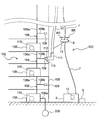
図10は、さらに別の実施形態に係る消火システム100の一部分を示す模式図である。より具体的には、図10は、消火システム100の消火液供給源から消火ホースの末端までの部分を示している。特に説明しない本実施形態の構成は、上述した実施形態の構成と同様であるため、その重複する説明を省略する。
図10に示す実施形態では、火災が発生している高層建築物105内に配置された給水システム102が上述した消火液供給源2として機能する。すなわち、少なくとも1つのドローン1,6に連結された消火ホース10は、給水システム102に連結され、消火液である水は給水システム102から消火ホース10に供給される。
以下では、火災が発生している高層建築物105内に配置された給水システム102に消火ホース10を連結して、消火活動を行う例が説明されるが、本実施形態は、この例に限定されない。一実施形態では、火災が発生している高層建築物105とは別の建物(例えば、高層建築物105に隣接する建物)内に配置された給水システムに消火ホース10を連結してもよい。
給水システム102は、複数の給水装置106と、各給水装置106から延びる給水管108とを含んでいる。図10には、複数のフロアにそれぞれ配置された複数の(3つの)給水装置106が描かれているが、給水装置106の数は、この例に限定されない。給水システム102は、1つの給水装置106のみを有していてもよい。すなわち、給水システム102は、少なくとも1つの給水装置106を有していればよい。
各給水装置106は、該給水装置106内を流れる水の圧力を増加させる給水ポンプ115を備えている。給水システム102が複数の給水装置106を有する場合は、隣接する給水装置106は、給水管108によって連結される。各給水管108は、主管108aと、主管108aから分岐した分岐管108bとを有している。最も下側に位置する給水装置106は、水道管200に連結された入口管106aを有しており、水道管200を流れる水は、入口管106aを介して最も下側に位置する給水装置106に吸い込まれる。このような給水システム102は、例えば、高層建築物105内に飲料水を供給する飲料水供給システムである。あるいは、給水システム102は、高層建築物105内に配置されたスプリンクラーシステムであってもよい。
分岐管108bは、その末端に、給水側コネクタ109を有している。消火ホース10の末端には、アタッチメント部材111が設けられており、このアタッチメント部材111は、分岐管108bの給水側コネクタ109と着脱自在に構成されるホース側コネクタ113を備えている。分岐管108bの給水側コネクタ109と、アタッチメント部材111のホース側コネクタ113とは、消火ホース10を給水管108の分岐管108bに連結する継手110として機能する。この継手110の例としては、ねじ込み継手、およびワンタッチジョイントが挙げられる。
継手110がワンタッチジョイントである場合は、ホース側コネクタ113を給水側コネクタ109に挿入するだけで、消火ホース10がアタッチメント部材111を介して分岐管108bに連結される。そのため、消火ホース10を、給水管108の分岐管108b(すなわち、消火液供給源である給水システム102)に素早く連結することができる。
本実施形態では、アタッチメント部材111は、L字状の断面形状を有している。アタッチメント部材111の一方の端部(すなわち、先端部)には、ホース側コネクタ113が配置され、他方の端部(すなわち、末端部)は、消火ホース10に連結される。アタッチメント部材111は、その内部に、給水システム102の給水管108から供給された水が流れる流路(図示せず)を有している。したがって、アタッチメント部材111のホース側コネクタ113を、分岐管108bの先端に設けられた給水側コネクタ109に接続すると、消火ホース10がアタッチメント部材111を介して給水システム102の給水管108に連通する。これにより、消火液としての水を、給水システム102から消火ホース10に供給することができる。
図10に示すように、上述した動力供給装置3と制御装置8とは、地上に配置される。図10には、最下端に配置された中継ドローン6のみが描かれているが、消火ホース10は、複数のドローン1,6に連結されている。複数のドローン1,6には、有線ケーブル4および中継ケーブル7を介して動力供給装置3の電源12から電力が供給される。したがって、消火活動中のトップドローン1および中継ドローン6の飛行時間には制約がない。その結果、トップドローン1および中継ドローン6を、火災が完全に消し止められるまで飛行させることができる。さらに、給水システム102に連結される消火ホース10には、水道管200を流れる水(消火液)を供給することができる。そのため、理論上、消火ホース10への水の供給量に制限がない。
さらに、図10に示される消火システムは、図8を参照して説明された補助ドローン30を有していてもよいし、図9を参照して説明された昇圧ポンプ(中継ポンプ)40を、消火ホース10の途中に配置してもよい。
図11A乃至図11Cは、図10に示すアタッチメント部材111を給水システム102に連結する工程を説明するための模式図である。より具体的には、図11Aは、アタッチメント部材111が接続される前の給水システム102の分岐管108bを拡大して示す模式図であり、図11Bは、給水システム102の分岐管108bに消火ホース10のアタッチメント部材111を接続する準備段階を示す模式図であり、図11Cは、給水システム102の分岐管108bに消火ホース10が連結された状態を示す模式図である。
図11Aに示すように、分岐管108bには、開閉弁120が設けられている。開閉弁120は、通常は閉じられている。開閉弁120を開くと、給水管108の主管108a内の水が分岐管108bを通って流れる。さらに、分岐管108bの先端に設けられた給水側コネクタ109は、高層建築物105の壁面に設けられた非常用開閉窓124に隣接している。非常用開閉窓124は、通常は閉じられている。一実施形態では、給水側コネクタ109は、高層建築物105の壁面に設けられた非常用扉(図示せず)に隣接していてもよい。あるいは、給水側コネクタ109は、高層建築物105の壁面から外部に突出していてもよい。
高層建築物105に火災が発生すると、図11Bに示すように、非常用開閉窓124が開かれる(または、取り外される)。次いで、消火ホース10の末端に接続されたアタッチメント部材111のホース側コネクタ113が分岐管108bの先端に設けられた給水側コネクタ109に対向するように、複数のドローン1,6の動作が制御装置8によって制御される。次いで、図11Cに示すように、高層建築物105の消火活動を行う作業者(例えば、消防隊員)がホース側コネクタ113を給水側コネクタ109に連結する。さらに、作業者は、分岐管108bに設けられた開閉弁120を開くことにより、水(消火液)が給水システム102から消火ホース10に供給される。
図12は、消火ホース10が連結管125を介して給水システム102の分岐管108bに連結される様子を示す模式図である。図12に示すように、連結管125を介して、消火ホース10を分岐管108bに連結してもよい。
連結管125の一端には、給水システム102の分岐管108bの先端に設けられた給水側コネクタ109と着脱自在に構成される第1連結管コネクタ125aが設けられる。分岐管108bの給水側コネクタ109と、連結管125の第1連結管コネクタ125aとは、連結管125を分岐管108bに連結する継手110aとして機能する。この継手110aの例としては、ねじ込み継手、およびワンタッチジョイントが挙げられる。
連結管125の他端には、アタッチメント部材111のホース側コネクタ113と着脱自在に構成される第2連結管コネクタ125bが設けられる。アタッチメント部材111のホース側コネクタ113と、連結管125の第2連結管コネクタ125bとは、連結管125をアタッチメント部材111に連結する継手110bとして機能する。この継手110bの例としては、ねじ込み継手、およびワンタッチジョイントが挙げられる。
連結管125の第1連結管コネクタ125aを、分岐管108bの給水側コネクタ109に連結し、連結管125の第2連結管コネクタ125bをアタッチメント部材111のホース側コネクタ113に連結することにより、消火ホース10が連結管125を介して給水システム102に連結される。一実施形態では、連結管125の代わりに、第1連結管コネクタ125aおよび第2連結管コネクタ125bを有する、フレキシブルな連結ホースを用いてもよい。このような構成により、分岐管108bが高層建築物105の壁面から離れていても、消火ホース10を給水システム102に連結することができる。
図13は、アタッチメント部材111の変形例を示す模式図である。図13に示すように、L字形状を有するアタッチメント部材111の屈曲部にカウンタウェイト130を取り付けてもよい。カウンタウェイト130は、ホース側コネクタ113が水平姿勢を保つように、アタッチメント部材111に取り付けられる重りである。このカウンタウェイト130によって、ホース側コネクタ113が水平姿勢を保てるので、ホース側コネクタ113を分岐管108bの給水側コネクタ109(または、連結管125の第2連結管コネクタ125b)に連結する作業性が向上する。
図14は、アタッチメント部材111の別の変形例を示す模式図である。図14に示すアタッチメント部材111は、上記カウンタウェイト130に加えて、アタッチメント部材111の内部に形成された流路を開閉可能な開閉弁132を備えている。消火ホース10を、アタッチメント部材111を介して給水システム102に接続した後で、開閉弁132を開くことにより、消火ホース10への水の供給が開始される。消火活動が終了した後で、開閉弁132を閉じることにより、消火ホース10内に残った水が給水システム102に逆流することが防止される。したがって、アタッチメント部材111を給水システム102の分岐管108bから取り外すときに、開閉弁132を閉じることにより、消火ホース10内に残った水が高層建築物105内に飛散することを防止することができる。一実施形態では、カウンタウェイト130を省略してもよい。
図15は、アタッチメント部材111のさらに別の変形例を示す模式図である。図15に示すアタッチメント部材111は、第1枝部111a、第2枝部111b、および第3枝部111cを有するT字形状を有する。第1枝部111aと第2枝部111bは、第3枝部111cから分岐して互いに逆向きに延びている。消火ホース10の末端は、第3枝部111cに連結されており、第1枝部111aの先端には、上述したホース側コネクタ113が配置されている。第1枝部111aと第3枝部111cとの接続部と、ホース側コネクタ113の間には、上述した開閉弁132が配置されている。第2枝部111bの先端には、ホース側コネクタ113と同一の構成を有するホース側コネクタ116が配置されている。第2枝部111bと第3枝部111cとの接続部と、ホース側コネクタ116の間には、上述した開閉弁132と同一の構成を有する開閉弁134が配置されている。
この実施形態に係るアタッチメント部材111によれば、ホース側コネクタ113またはホース側コネクタ116のいずれか一方を、分岐管108bの給水側コネクタ109に連結することができる。したがって、消火活動を行う作業者は、ホース側コネクタ113またはホース側コネクタ116のいずれか一方を捕まえれば、消火ホース10を給水システム102に連結することができるので、消火活動の作業性が向上する。ホース側コネクタ113(または、ホース側コネクタ116)を、分岐管108bの給水側コネクタ109に連結したときは、開閉弁132(または、開閉弁134)を開き、開閉弁134(または、開閉弁132)を閉じる。この作業を実施することにより、給水システム102から供給された水が、ホース側コネクタ116(または、ホース側コネクタ113)から放出されることが防止される。
第1枝部111aと第2枝部111bは、第3枝部111cに対して鏡面対称に配置されるのが好ましい。さらに、開閉弁132と開閉弁134も、第3枝部111cに対して鏡面対称に配置されるのが好ましい。このような構成により、カウンタウェイトを設けなくても、ホース側コネクタ116およびホース側コネクタ113の水平姿勢を維持することができる。
図16は、アタッチメント部材111のさらに別の変形例を示す模式図である。図16に示すアタッチメント部材111は、推力発生機構として機能する回転翼111Rを備えたドローンとして構成されている。アタッチメント部材111には、動力供給装置3(図10参照)から延びる中継ケーブル7が接続されており、回転翼111Rを回転させる電力は、動力供給装置3から中継ケーブル7を介してアタッチメント部材111に供給される。アタッチメント部材111よりも上方に位置する中継ドローン6には、アタッチメント部材111から延びる中継ケーブル7によって電力が供給される。
図16に示すアタッチメント部材111の動作は、制御装置8によって制御される。したがって、アタッチメント部材111を容易に分岐管108bの給水側コネクタ113に接近させることができる。分岐管108bの給水側コネクタ109と、アタッチメント部材111のホース側コネクタ113とによって構成される継手110がワンタッチジョイントの場合は、制御装置8がアタッチメント部材111の動作を制御することによって、自動で、アタッチメント部材111のホース側コネクタ113を分岐管108bの給水側コネクタ109に連結することができる。このアタッチメント部材111によれば、消火ホース10を給水システム102に容易かつ自動で連結することができるので、消火活動の作業性が向上する。
図示はしないが、ドローンとして構成されるアタッチメント部材111は、回転翼111Rを回転させる内燃機関を有していてもよい。さらに、アタッチメント部材111は、回転翼111Rの代わりに、電力、または内燃機関によって回転するロータを有していてもよいし、図6を参照して説明されたエンジン35を有していてもよいし、図7を参照して説明された噴射ノズル37を有していてもよい。
図17は、アタッチメント部材111のさらに別の変形例を示す模式図である。図17に示すアタッチメント部材111は、ワイヤなどの連結具17を介して複数の(本実施形態では2つの)中継ドローン6に連結されている。一実施形態では、アタッチメント部材111は、1つの中継ドローン6のみに連結されてもよい。制御装置8は、アタッチメント部材111に連結された中継ドローン6の動作を制御することにより、アタッチメント部材111のホース側コネクタ113を分岐管108bの給水側コネクタ109に近接または連結することができる。さらに、制御装置8は、アタッチメント部材111に連結された中継ドローン6の動作を制御することにより、ホース側コネクタ116の水平姿勢を維持することができる。したがって、本実施形態に係るアタッチメント部材111によれば、消火ホース10を給水システム102に容易に連結することができるので、消火活動の作業性が向上する。
上述した実施形態は、本発明が属する技術分野における通常の知識を有する者が本発明を実施できることを目的として記載されたものである。上記実施形態の種々の変形例は、当業者であれば当然になしうることであり、本発明の技術的思想は他の実施形態にも適用しうる。したがって、本発明は、記載された実施形態に限定されることはなく、特許請求の範囲によって定義される技術的思想に従った最も広い範囲とすべきである。
本発明は、ドローンに連結された消火ホースのノズルを高所まで搬送するための消火システムに利用可能である。
1 トップドローン
2 消火液供給源
3 動力供給装置
4 有線ケーブル
6 中継ドローン
7 中継ケーブル
8 制御装置
10 消火ホース
11 ノズル
12 電源
13 内燃機関
15 ポンプ
17 連結具(ワイヤ)
18 太陽電池パネル
19 コンプレッサ
21 吊り具(ワイヤ)
24 射出機構
25 アンカー
26 係合フック
28 爪
29 棒状部材
30 補助ドローン
31 補助有線ケーブル
32 連結具(ワイヤ)
35 エンジン
37 噴射ノズル
40 昇圧ポンプ(中継ポンプ)
100 消火システム
102 給水システム
105 高層建築物
106 給水装置
108 給水管
109 給水側コネクタ
110,110a,110b 継手
111 アタッチメント部材
113,116 ホース側コネクタ
125 連結管
125a,125b 連結管コネクタ
130 カウンタウェイト
132,134 開閉弁
Claims (21)
- 消火液を噴射するノズルを有する消火ホースと、
前記消火ホースに連結され、前記消火液を前記消火ホースに供給する消火液供給源と、
前記ノズルに連結されるトップドローンと、
前記トップドローンに連結される有線ケーブルと、
前記トップドローンを飛行させる動力または燃料を、前記有線ケーブルを介して供給する動力供給装置と、を備えることを特徴とする消火システム。 - 前記動力供給装置は、前記トップドローンに電力を供給する電源を含み、
前記トップドローンは、前記電力により回転する回転翼またはロータを有することを特徴とする請求項1に記載の消火システム。 - 前記動力供給装置は、前記トップドローンに燃料を供給するポンプ装置を含み、
前記トップドローンは、前記燃料を燃焼させることにより回転翼またはロータを回転させる内燃機関を有することを特徴とする請求項1に記載の消火システム。 - 前記動力供給装置は、前記トップドローンにジェット燃料を供給するポンプ装置を含み、
前記トップドローンは、前記ジェット燃料を燃焼させることにより推力を得るジェットエンジンを有することを特徴とする請求項1に記載の消火システム。 - 前記動力供給装置は、前記トップドローンに気体燃料および気体酸化剤を供給するポンプ装置を含み、
前記トップドローンは、前記気体燃料および前記気体酸化剤の混合燃料を燃焼させることにより推力を得る気体ロケットエンジンを有することを特徴とする請求項1に記載の消火システム。 - 前記動力供給装置は、前記トップドローンに固体燃料を供給するポンプ装置を含み、
前記トップドローンは、前記固体燃料を燃焼させることにより推力を得る固体ロケットエンジンを有することを特徴とする請求項1に記載の消火システム。 - 前記動力供給装置は、前記トップドローンに加圧流体を供給するポンプ装置またはコンプレッサを含み、
前記トップドローンは、前記加圧流体を噴射することにより推力を得る噴射ノズルを有することを特徴とする請求項1に記載の消火システム。 - 前記消火ホースの途中に連結される少なくとも1つの中継ドローンと、
前記中継ドローンに連結される中継ケーブルと、をさらに備え、
前記トップドローンと前記中継ドローンは、前記有線ケーブルおよび前記中継ケーブルによって直列に連結されており、
前記トップドローンおよび前記中継ドローンを飛行させる動力または燃料は、前記有線ケーブルおよび前記中継ケーブルを介して前記動力供給装置から供給されることを特徴とする請求項1乃至7のいずれか一項に記載の消火システム。 - 前記消火ホースの途中に配置された昇圧ポンプをさらに備え、
前記中継ドローンは、前記昇圧ポンプに連結されることを特徴とする請求項8に記載の消火システム。 - 前記消火ホースの姿勢を調整するために、前記消火ホースに連結される少なくとも1つの補助ドローンと、
前記補助ドローンに連結される補助有線ケーブルと、をさらに備え、
前記トップドローンと前記補助ドローンは、前記補助有線ケーブルによって直列に連結されており、
前記補助ドローンを飛行させる動力または燃料は、前記有線ケーブルおよび前記補助連結ケーブルを介して前記動力供給装置から供給されることを特徴とする請求項1乃至9のいずれか一項に記載の消火システム。 - 前記ノズルは、第1枝管、第2枝管、および第3枝管を有するT字形状を有し、
前記第1枝管と前記第2枝管は、前記第3枝管から分岐して互いに逆向きに延びており、
前記消火液は、前記第3枝管に流入して、前記第1枝管および前記第2枝管から噴射されることを特徴とする請求項1乃至9のいずれか一項に記載の消火システム。 - 前記トップドローンは、アンカーを射出するための射出装置を備えることを特徴とする請求項1乃至9のいずれか一項に記載の消火システム。
- 前記トップドローンには、太陽電池パネルが配置されており、
前記太陽電池パネルは、前記射出装置を駆動するための電力の少なくとも一部を該射出装置に供給することを特徴とする請求項12に記載の消火システム。 - 前記トップドローンは、係合フックを備えており、
前記係合フックは、棒状部材に係合可能な爪を有していることを特徴とする請求項1乃至9のいずれか一項に記載の消火システム。 - 前記消火液供給源は、建物に設置された給水システムであり、
前記給水システムは、少なくとも1つのポンプと、該ポンプから延びる給水管とを有しており、
前記消火ホースは、その末端に、前記給水システムに連結可能なアタッチメント部材を有していることを特徴とする請求項8に記載の消火システム。 - 前記アタッチメント部材を、前記給水システムに連結するための連結管または連結ホースをさらに備えることを特徴とする請求項15に記載の消火システム。
- 前記アタッチメント部材は、該アタッチメント部材を前記給水システムの分岐管に設けられた給水側コネクタに連結するためのホース側コネクタを有しており、
前記アタッチメント部材には、前記ホース側コネクタの水平姿勢を維持するためのカウンタウェイトが取り付けられていることを特徴とする請求項15または16に記載の消火システム。 - 前記アタッチメント部材は、その内部に形成された流路を開閉するための開閉弁を有していることを特徴とする請求項15乃至17のいずれか一項に記載の消火システム。
- 前記アタッチメント部材は、第1枝部、第2枝部、および第3枝部からなるT字形状を有しており、
前記第1枝部と前記第2枝部は、前記消火ホースが連結される前記第3枝部から分岐して互いに逆向きに延びており、
前記第1枝部と前記第2枝部には、それぞれ、開閉弁が配置されていることを特徴とする請求項15または16に記載の消火システム。 - 前記アタッチメント部材は、推力発生機構を備えたドローンとして構成されることを特徴とする請求項15乃至19に記載の消火システム。
- 前記アタッチメント部材は、前記中継ドローンに連結されることを特徴とする請求項15に記載の消火システム。
Priority Applications (1)
| Application Number | Priority Date | Filing Date | Title |
|---|---|---|---|
| US17/048,893 US20210138281A1 (en) | 2018-04-25 | 2019-04-19 | Fire fighting system using drone |
Applications Claiming Priority (4)
| Application Number | Priority Date | Filing Date | Title |
|---|---|---|---|
| JP2018-083905 | 2018-04-25 | ||
| JP2018083905 | 2018-04-25 | ||
| JP2018213059A JP7214446B2 (ja) | 2018-04-25 | 2018-11-13 | ドローンを用いた消火システム |
| JP2018-213059 | 2018-11-13 |
Publications (1)
| Publication Number | Publication Date |
|---|---|
| WO2019208440A1 true WO2019208440A1 (ja) | 2019-10-31 |
Family
ID=68295333
Family Applications (1)
| Application Number | Title | Priority Date | Filing Date |
|---|---|---|---|
| PCT/JP2019/016841 WO2019208440A1 (ja) | 2018-04-25 | 2019-04-19 | ドローンを用いた消火システム |
Country Status (1)
| Country | Link |
|---|---|
| WO (1) | WO2019208440A1 (ja) |
Cited By (8)
| Publication number | Priority date | Publication date | Assignee | Title |
|---|---|---|---|---|
| DE102020114605A1 (de) | 2020-06-02 | 2021-12-02 | Nickel Holding Gmbh | Flüssigkeitstransport- und Verteilersystem |
| US20220023685A1 (en) * | 2019-02-20 | 2022-01-27 | Ebara Corporation | Drone system |
| CN114100043A (zh) * | 2020-09-01 | 2022-03-01 | 中国石油化工股份有限公司 | 泡沫灭火系统以及泡沫灭火方法 |
| CN114788936A (zh) * | 2022-06-23 | 2022-07-26 | 吉林大学 | 一种复杂空间内无人机集群协作接力灭火系统 |
| CN115430088A (zh) * | 2022-09-19 | 2022-12-06 | 梁计谋 | 一种消防灭火用室内灭火装置 |
| CN115430084A (zh) * | 2022-09-13 | 2022-12-06 | 邓秋波 | 一种高层建筑室内救援系统及其使用方法 |
| CN115593629A (zh) * | 2022-11-07 | 2023-01-13 | 广州涡特泷科技有限公司(Cn) | 一种多机串联的无人机 |
| WO2023014315A1 (en) * | 2021-08-03 | 2023-02-09 | Yavuz Davut | An unmanned aerial vehicle |
Citations (7)
| Publication number | Priority date | Publication date | Assignee | Title |
|---|---|---|---|---|
| JPS6486984A (en) * | 1987-07-21 | 1989-03-31 | Buranto Harii | Rescue craft |
| WO2014080385A2 (en) * | 2014-03-25 | 2014-05-30 | Wasfi Alshdaifat | Firefighters drone arrangement |
| US20170043872A1 (en) * | 2014-07-08 | 2017-02-16 | Todd Michael Whitaker | Tethered unmanned aerial vehicle fire fighting system |
| US20170113787A1 (en) * | 2015-10-27 | 2017-04-27 | Kim F. Hein | Hydraulically Propelled Drone for Delivering Firefighting fluid |
| JP2017149402A (ja) * | 2015-10-02 | 2017-08-31 | インサイツ インク. | 無人航空機のための空中発射及び/又は回収、並びに関連するシステム及び方法 |
| CN107308569A (zh) * | 2017-08-17 | 2017-11-03 | 佛山市领卓科技有限公司 | 一种灭火系统及灭火方式 |
| WO2018046973A2 (en) * | 2016-09-02 | 2018-03-15 | Zisopoulos Athanasios | Airborne pipeline docked to an earth reservoir to deliver water over long distance for aerial firefighting and irrigation. |
-
2019
- 2019-04-19 WO PCT/JP2019/016841 patent/WO2019208440A1/ja active Application Filing
Patent Citations (7)
| Publication number | Priority date | Publication date | Assignee | Title |
|---|---|---|---|---|
| JPS6486984A (en) * | 1987-07-21 | 1989-03-31 | Buranto Harii | Rescue craft |
| WO2014080385A2 (en) * | 2014-03-25 | 2014-05-30 | Wasfi Alshdaifat | Firefighters drone arrangement |
| US20170043872A1 (en) * | 2014-07-08 | 2017-02-16 | Todd Michael Whitaker | Tethered unmanned aerial vehicle fire fighting system |
| JP2017149402A (ja) * | 2015-10-02 | 2017-08-31 | インサイツ インク. | 無人航空機のための空中発射及び/又は回収、並びに関連するシステム及び方法 |
| US20170113787A1 (en) * | 2015-10-27 | 2017-04-27 | Kim F. Hein | Hydraulically Propelled Drone for Delivering Firefighting fluid |
| WO2018046973A2 (en) * | 2016-09-02 | 2018-03-15 | Zisopoulos Athanasios | Airborne pipeline docked to an earth reservoir to deliver water over long distance for aerial firefighting and irrigation. |
| CN107308569A (zh) * | 2017-08-17 | 2017-11-03 | 佛山市领卓科技有限公司 | 一种灭火系统及灭火方式 |
Cited By (12)
| Publication number | Priority date | Publication date | Assignee | Title |
|---|---|---|---|---|
| US20220023685A1 (en) * | 2019-02-20 | 2022-01-27 | Ebara Corporation | Drone system |
| US11975225B2 (en) * | 2019-02-20 | 2024-05-07 | Ebara Corporation | Drone system |
| DE102020114605A1 (de) | 2020-06-02 | 2021-12-02 | Nickel Holding Gmbh | Flüssigkeitstransport- und Verteilersystem |
| DE102020114605B4 (de) | 2020-06-02 | 2022-06-09 | Nickel Holding Gmbh | Flüssigkeitstransport- und Verteilersystem |
| CN114100043A (zh) * | 2020-09-01 | 2022-03-01 | 中国石油化工股份有限公司 | 泡沫灭火系统以及泡沫灭火方法 |
| CN114100043B (zh) * | 2020-09-01 | 2023-02-17 | 中国石油化工股份有限公司 | 泡沫灭火系统以及泡沫灭火方法 |
| WO2023014315A1 (en) * | 2021-08-03 | 2023-02-09 | Yavuz Davut | An unmanned aerial vehicle |
| CN114788936A (zh) * | 2022-06-23 | 2022-07-26 | 吉林大学 | 一种复杂空间内无人机集群协作接力灭火系统 |
| CN115430084A (zh) * | 2022-09-13 | 2022-12-06 | 邓秋波 | 一种高层建筑室内救援系统及其使用方法 |
| CN115430084B (zh) * | 2022-09-13 | 2023-04-14 | 邓秋波 | 一种高层建筑室内救援系统及其使用方法 |
| CN115430088A (zh) * | 2022-09-19 | 2022-12-06 | 梁计谋 | 一种消防灭火用室内灭火装置 |
| CN115593629A (zh) * | 2022-11-07 | 2023-01-13 | 广州涡特泷科技有限公司(Cn) | 一种多机串联的无人机 |
Similar Documents
| Publication | Publication Date | Title |
|---|---|---|
| JP7214446B2 (ja) | ドローンを用いた消火システム | |
| WO2019208440A1 (ja) | ドローンを用いた消火システム | |
| RU2620400C2 (ru) | Авиационная система пожаротушения | |
| US5135055A (en) | Ground and airborne fire fighting system and method of fighting high rise building fires | |
| JP6480573B2 (ja) | 噴霧噴射放出装置 | |
| KR102209056B1 (ko) | 드론을 이용한 산불 진화 시스템 및 그 방법 | |
| JP2019193766A5 (ja) | ||
| US20080099212A1 (en) | Modified Fire Fighting Truck | |
| WO2020170479A1 (ja) | ドローンシステム | |
| KR102085822B1 (ko) | 수압에 의해 비상 가능한 소방용 드론 관창 | |
| KR102136950B1 (ko) | 유체 분사용 무인비행체의 프로펠러 가속장치 | |
| RU2289531C1 (ru) | Устройство пожаротушения высотных зданий с применением вертолета | |
| JP2004065905A (ja) | 高層ビル火災の外部からの消火システム | |
| KR101053727B1 (ko) | 이동식 초고압 소방포 | |
| KR200431869Y1 (ko) | 휴대용 산불 진화장치 | |
| CN210096729U (zh) | 高空飞行消防装置 | |
| JP2003190314A (ja) | 二流体消火装置 | |
| KR102399521B1 (ko) | 복수의 드론을 이용한 산불 진화 시스템 | |
| CN209984827U (zh) | 系留无人机及基于系留无人机的灭火系统 | |
| CN210592444U (zh) | 一种结合烟雾机的植保无人机 | |
| CN110201337B (zh) | 一种可自主飞行的高压喷头及其应用 | |
| JPH03157298A (ja) | 消防ヘリコプタ | |
| JP5681748B2 (ja) | 消火装置 | |
| RU117297U1 (ru) | Устройство пожаротушения (варианты) | |
| JP3735644B2 (ja) | ヘリコプターによる消火装置 |
Legal Events
| Date | Code | Title | Description |
|---|---|---|---|
| 121 | Ep: the epo has been informed by wipo that ep was designated in this application |
Ref document number: 19793886 Country of ref document: EP Kind code of ref document: A1 |
|
| NENP | Non-entry into the national phase |
Ref country code: DE |
|
| 122 | Ep: pct application non-entry in european phase |
Ref document number: 19793886 Country of ref document: EP Kind code of ref document: A1 |